US7478460B2 - Shear fasteners - Google Patents
Shear fasteners Download PDFInfo
- Publication number
- US7478460B2 US7478460B2 US10/785,133 US78513304A US7478460B2 US 7478460 B2 US7478460 B2 US 7478460B2 US 78513304 A US78513304 A US 78513304A US 7478460 B2 US7478460 B2 US 7478460B2
- Authority
- US
- United States
- Prior art keywords
- engageable
- fastener
- sheet
- fastener component
- elements
- Prior art date
- Legal status (The legal status is an assumption and is not a legal conclusion. Google has not performed a legal analysis and makes no representation as to the accuracy of the status listed.)
- Expired - Lifetime, expires
Links
Images


Classifications
-
- B—PERFORMING OPERATIONS; TRANSPORTING
- B65—CONVEYING; PACKING; STORING; HANDLING THIN OR FILAMENTARY MATERIAL
- B65D—CONTAINERS FOR STORAGE OR TRANSPORT OF ARTICLES OR MATERIALS, e.g. BAGS, BARRELS, BOTTLES, BOXES, CANS, CARTONS, CRATES, DRUMS, JARS, TANKS, HOPPERS, FORWARDING CONTAINERS; ACCESSORIES, CLOSURES, OR FITTINGS THEREFOR; PACKAGING ELEMENTS; PACKAGES
- B65D63/00—Flexible elongated elements, e.g. straps, for bundling or supporting articles
- B65D63/10—Non-metallic straps, tapes, or bands; Filamentary elements, e.g. strings, threads or wires; Joints between ends thereof
- B65D63/1018—Joints produced by application of integral securing members, e.g. buckles, wedges, tongue and slot, locking head and teeth or the like
- B65D63/1027—Joints produced by application of integral securing members, e.g. buckles, wedges, tongue and slot, locking head and teeth or the like the integral securing member being formed as a female and male locking member, e.g. locking head and locking teeth, or the like
- B65D63/1063—Joints produced by application of integral securing members, e.g. buckles, wedges, tongue and slot, locking head and teeth or the like the integral securing member being formed as a female and male locking member, e.g. locking head and locking teeth, or the like the female locking member being provided with at least one plastic barb
-
- A—HUMAN NECESSITIES
- A44—HABERDASHERY; JEWELLERY
- A44B—BUTTONS, PINS, BUCKLES, SLIDE FASTENERS, OR THE LIKE
- A44B13/00—Hook or eye fasteners
- A44B13/0005—Hook or eye fasteners characterised by their material
- A44B13/0023—Hook or eye fasteners characterised by their material made of plastics
-
- A—HUMAN NECESSITIES
- A44—HABERDASHERY; JEWELLERY
- A44B—BUTTONS, PINS, BUCKLES, SLIDE FASTENERS, OR THE LIKE
- A44B13/00—Hook or eye fasteners
- A44B13/0052—Strips of hook or eye fasteners
-
- B—PERFORMING OPERATIONS; TRANSPORTING
- B29—WORKING OF PLASTICS; WORKING OF SUBSTANCES IN A PLASTIC STATE IN GENERAL
- B29C—SHAPING OR JOINING OF PLASTICS; SHAPING OF MATERIAL IN A PLASTIC STATE, NOT OTHERWISE PROVIDED FOR; AFTER-TREATMENT OF THE SHAPED PRODUCTS, e.g. REPAIRING
- B29C43/00—Compression moulding, i.e. applying external pressure to flow the moulding material; Apparatus therefor
- B29C43/22—Compression moulding, i.e. applying external pressure to flow the moulding material; Apparatus therefor of articles of indefinite length
- B29C43/222—Compression moulding, i.e. applying external pressure to flow the moulding material; Apparatus therefor of articles of indefinite length characterised by the shape of the surface
-
- F—MECHANICAL ENGINEERING; LIGHTING; HEATING; WEAPONS; BLASTING
- F16—ENGINEERING ELEMENTS AND UNITS; GENERAL MEASURES FOR PRODUCING AND MAINTAINING EFFECTIVE FUNCTIONING OF MACHINES OR INSTALLATIONS; THERMAL INSULATION IN GENERAL
- F16B—DEVICES FOR FASTENING OR SECURING CONSTRUCTIONAL ELEMENTS OR MACHINE PARTS TOGETHER, e.g. NAILS, BOLTS, CIRCLIPS, CLAMPS, CLIPS OR WEDGES; JOINTS OR JOINTING
- F16B5/00—Joining sheets or plates, e.g. panels, to one another or to strips or bars parallel to them
- F16B5/07—Joining sheets or plates, e.g. panels, to one another or to strips or bars parallel to them by means of multiple interengaging protrusions on the surfaces, e.g. hooks, coils
-
- B—PERFORMING OPERATIONS; TRANSPORTING
- B29—WORKING OF PLASTICS; WORKING OF SUBSTANCES IN A PLASTIC STATE IN GENERAL
- B29C—SHAPING OR JOINING OF PLASTICS; SHAPING OF MATERIAL IN A PLASTIC STATE, NOT OTHERWISE PROVIDED FOR; AFTER-TREATMENT OF THE SHAPED PRODUCTS, e.g. REPAIRING
- B29C43/00—Compression moulding, i.e. applying external pressure to flow the moulding material; Apparatus therefor
- B29C43/32—Component parts, details or accessories; Auxiliary operations
- B29C43/44—Compression means for making articles of indefinite length
- B29C43/46—Rollers
- B29C2043/461—Rollers the rollers having specific surface features
- B29C2043/465—Rollers the rollers having specific surface features having one or more cavities, e.g. for forming distinct products
-
- B—PERFORMING OPERATIONS; TRANSPORTING
- B29—WORKING OF PLASTICS; WORKING OF SUBSTANCES IN A PLASTIC STATE IN GENERAL
- B29L—INDEXING SCHEME ASSOCIATED WITH SUBCLASS B29C, RELATING TO PARTICULAR ARTICLES
- B29L2031/00—Other particular articles
- B29L2031/727—Fastening elements
- B29L2031/729—Hook and loop-type fasteners
-
- Y—GENERAL TAGGING OF NEW TECHNOLOGICAL DEVELOPMENTS; GENERAL TAGGING OF CROSS-SECTIONAL TECHNOLOGIES SPANNING OVER SEVERAL SECTIONS OF THE IPC; TECHNICAL SUBJECTS COVERED BY FORMER USPC CROSS-REFERENCE ART COLLECTIONS [XRACs] AND DIGESTS
- Y10—TECHNICAL SUBJECTS COVERED BY FORMER USPC
- Y10T—TECHNICAL SUBJECTS COVERED BY FORMER US CLASSIFICATION
- Y10T24/00—Buckles, buttons, clasps, etc.
- Y10T24/27—Buckles, buttons, clasps, etc. including readily dissociable fastener having numerous, protruding, unitary filaments randomly interlocking with, and simultaneously moving towards, mating structure [e.g., hook-loop type fastener]
- Y10T24/2708—Combined with diverse fastener
-
- Y—GENERAL TAGGING OF NEW TECHNOLOGICAL DEVELOPMENTS; GENERAL TAGGING OF CROSS-SECTIONAL TECHNOLOGIES SPANNING OVER SEVERAL SECTIONS OF THE IPC; TECHNICAL SUBJECTS COVERED BY FORMER USPC CROSS-REFERENCE ART COLLECTIONS [XRACs] AND DIGESTS
- Y10—TECHNICAL SUBJECTS COVERED BY FORMER USPC
- Y10T—TECHNICAL SUBJECTS COVERED BY FORMER US CLASSIFICATION
- Y10T24/00—Buckles, buttons, clasps, etc.
- Y10T24/27—Buckles, buttons, clasps, etc. including readily dissociable fastener having numerous, protruding, unitary filaments randomly interlocking with, and simultaneously moving towards, mating structure [e.g., hook-loop type fastener]
- Y10T24/2792—Buckles, buttons, clasps, etc. including readily dissociable fastener having numerous, protruding, unitary filaments randomly interlocking with, and simultaneously moving towards, mating structure [e.g., hook-loop type fastener] having mounting surface and filaments constructed from common piece of material
Definitions
- This invention relates to fastener products such as those having an array of projections arranged to resist shear displacement across the surface of the fastener product.
- Some fasteners for example, hook and loop fasteners, include fastener components with engageable elements constructed to engage elements of corresponding fastener components.
- the fastener elements of the two fastener components are similar or the same, and the two fastener components may be regions of a single sheet.
- a self-engageable fastener component includes a sheet-form base, and an array of wedge-shaped, engageable elements extending integrally from at least one side of the sheet-form base.
- the engageable elements each have an engageable side, and a non-engageable side conterminous at an upper edge of the element.
- the upper edge of each engageable element defines a curve in top view, and the engageable sides of a majority of the elements are oriented in a common direction.
- the engageable elements are arranged in at least one row along the sheet-form base, the row extending toward the single edge.
- the elements are arranged in an array of multiple rows and columns.
- the elements are arranged in multiple rows, with elements of adjacent rows offset from one another along their respective rows. The elements of adjacent rows are offset, for example, by about one-half a nominal spacing between adjacent elements within a row.
- the curve defined by the upper edge in top view is substantially circular with a constant radius of curvature.
- the constant radius of curvature is from about 0.25 to 2.5 centimeters.
- the curve defined by the upper edge in top view is not circular, but is, for example, parabolic, ellipsoidal, hyperbolic, or a mixture of such curves.
- a maximum elevation of the upper edge above the top surface of the sheet-form base is between about 0.025 and 6.3 millimeters
- each engageable element has a width, measured along the sheet-form base perpendicular to said single edge, of between about 0.13 and 6.3 millimeters
- each engageable element has a length, measured along the sheet-form base parallel to the edge, of between about 0.13 and 2.54 centimeters
- the non-engageable side of each fastener element rises from the sheet-form base at an angle of between about 5 and 45 degrees.
- the engageable sides of the wedge-shaped elements overhang the sheet-form base, and the engageable side of each fastener element extends downward from the upper edge toward the sheet-form base at an undercut angle, measured in a midplane bisecting the fastener element and perpendicular to the sheet-form base, of between about 10 and 45 degrees.
- the engageable elements extend outwardly from two opposite sides of the sheet-form base. In some instances, there are hook-shaped projections, and/or engageable loops proximate the wedge-shaped elements.
- the sheet-form base forms a tube, with the wedge-shaped elements extending from a curved surface of the tube.
- the curved surface can include an outer, or an inner surface of the tube.
- the tube defines a longitudinal gap extending along its length between opposite edges of the sheet-form base.
- the sheet-form base forms an elongated, U-shaped structure, and the wedge-shaped elements extend from an inside surface of the U-shaped structure, a majority of the engageable sides of the wedge-shaped elements directed away from an open edge of the U-shaped structure.
- the wedge-shaped elements extend from an outside surface of the U-shaped structure.
- the sheet-form base forms an elongated strap.
- the elongated strap includes only a single row of said wedge-shaped elements, all arranged with their engageable sides directed toward an end of the strap.
- an aperture is defined adjacent one end of the strap, and the aperture sized to receive an opposite end of the strap therethrough.
- the elongated strap includes an exposed retention edge along one side of the aperture, the retention edge is positioned to engage the engageable sides of the wedge-shaped elements with the opposite end of the strap pulled through the aperture, to resist removal of the strap from the aperture.
- the sheet-form base is secured to, and overlays a layer of resilient material, and the sheet-form base is flexible.
- two fastener components are arranged with the engageable sides of their wedge-shaped elements overlapping one another to resist shear motion between the fastener components.
- a method of making a fastener component includes providing a molding tool defining an array of cavities extending inwardly from an outer surface thereof.
- the moldable resin is transferred onto the outer surface of the molding tool, and the resin is pressed into the cavities of the molding tool, thus forming the engageable elements, while forming a base of resin on the surface of the molding tool, the base interconnecting the engageable elements.
- the cavities form engageable elements that are wedge-shaped, each wedge-shaped element including an engageable side, and a non-engageable side conterminous at an upper edge of the element.
- the upper edge of each engageable element defines a curve in top view, and the engageable sides of a majority of the elements are oriented toward a single edge of the sheet-form base.
- the molding tool includes, for example, a rotatable mold roll positioned adjacent a counter-rotating pressure roll to define a pressure nip in which the moldable resin is pressed into the cavities to form the engageable elements.
- a sheet material is introduced into the nip with the moldable resin, and laminating the moldable resin to the sheet material under pressure in the nip.
- the sheet material can include, for example, a scrim material.
- the planar sheet material is formed into a tube, the engageable sides of a majority of the engageable elements being directed away from a common, open end of the tube.
- the fastener component is in strap form
- the method includes forming an aperture at one end of the fastener component, the aperture being sized to receive an opposite end of the fastener component.
- the fastener component includes an exposed retention edge along one side of the aperture, the retention edge being positioned to engage the engageable sides of the wedge-shaped elements with the opposite end of the strap pulled through the aperture, resisting removal of the strap from the aperture.
- a seat bun includes a compliant material with a surface having a central region bounded on two opposite sides by elongated trenches, and a fastener component that includes a sheet-form base, and an array of wedge-shaped, engageable elements extending integrally from at least one side of the sheet-form base disposed within each trench.
- the engageable elements each have an engageable side, and a non-engageable side conterminous at an upper edge of the element.
- the upper edge of each engageable element defines a curve in top view, and the engageable sides of a majority of the elements are oriented in a common direction.
- the elements are arranged with the non-engageable sides of its wedge-shaped elements directed out of the trench.
- the fastener components include elongated, U-shaped structures extending along each trench. In some instances, the fastener components comprise tubular structures embedded within each trench.
- curve as used herein is intended to include generally curved outlines that may encompass minor discontinuities or straight segments.
- fastener components and fasteners disclosed herein can be particularly useful in applications requiring high shear strength.
- many of the fastener components and systems disclosed herein provide for ready disengagement and in-place fastener adjustability.
- Many embodiments can be molded in flexible form, with very low profile wedges, such that engaged sets of the fasteners occupy very little width between mating surfaces.
- the wedges can be arranged to allow engaged surfaces to be readily shifted for adjustment along rows of wedges, such as for adjusting the position of a picture frame fastened to a wall surface with such fasteners, for example, with the curved edges of the wedges of each row defining a series of detents for maintaining final engagement once shear load is reestablished between the wedges.
- the curvature of the edges helps to assist with adjustment of two mating arrays of wedges by allowing the apexes of the wedges to slide across one another without completely separating the mating fastener components, with the wedges overlapping.
- FIG. 1 is a perspective view of a fastener component according to one embodiment.
- FIG. 1A is an enlarged top view of a portion of the fastener component shown in FIG. 1 .
- FIG. 1B is an enlarged side view of a portion of the fastener component shown in FIG. 1 .
- FIG. 1C is a perspective view of a fastener component according to an alternative embodiment.
- FIG. 1D is a top view of the fastener component of FIG. 1C .
- FIG. 2 is a top view of the fastener component shown in FIG. 1 .
- FIG. 2A is a cross-sectional view of the fastener component shown in FIG. 2 , taken along line 2 A- 2 A in FIG. 2 .
- FIG. 2B is an enlarged view of a portion of the fastener component shown in FIG. 2A .
- FIG. 3 is a top view of the fastener component shown in FIG. 2 , the fastener component oriented such that it is engaging a like fastener component, creating a fastener according to one embodiment.
- FIG. 3A is a cross-sectional view of the fastener shown in FIG. 3 , taken along 3 A- 3 A.
- FIGS. 3B-3C are top views of a portion of the fastener system illustrated in FIG. 3 .
- FIG. 4 is a diagrammatic view of a process for making the fastener component shown in FIG. 1 .
- FIG. 4A is a diagrammatic view of a process for making a fastener component shown in FIG. 4B or 4 C.
- FIG. 4B is a laminated fastener component made by the process shown in FIG. 4A .
- FIG. 4C is a fastener component made by the process shown in FIG. 4A using a scrim web material.
- FIG. 4D is a diagrammatic view of a process for making a fastener component with engageable elements on both sides of a sheet-form base.
- FIG. 5 is a diagrammatic view of an alternative process for making the fastener component shown in FIG. 1 .
- FIG. 6 is a diagrammatic top view of a portion of flat tooling.
- FIG. 7 is a cross-sectional view of a tool roll being cut.
- FIG. 7A is a side view of a dovetail cutter.
- FIG. 7B is an end view of a dovetail cutter.
- FIGS. 8-9 are perspective views illustrating formation of a tubular fastener component with engaging elements on the inside.
- FIG. 9A is a cross-sectional view of the fastener component shown in FIG. 9 (after joining), taken along line 9 A- 9 A in FIG. 9 .
- FIGS. 10-11 are perspective views illustrating formation of a tubular fastener component with engaging elements on the outside.
- FIG. 11A is a cross-sectional view of the fastener component shown in FIG. 11 , taken along line 11 A- 11 A in FIG. 11 .
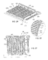
- FIG. 12 is a perspective view of a tubular fastener system employing the tubular fastener components shown in FIGS. 9 and 11 .
- FIG. 13 is a perspective view of the tubular fastener component shown in FIG. 9A in a plastic body.
- FIG. 13A is a side view of a fastener component according to an embodiment.
- FIG. 13B is a side view of a fastener component according to another embodiment.
- FIG. 13C is a cross-sectional view of a fastener system employing the fastener components of FIGS. 13A and 13B .
- FIG. 14 is a perspective view of a mold insert illustrating the tubular fastener component of FIG. 9 (after joining) on a protrusion.
- FIG. 14A is a cross-sectional view of a tubular fastener component on a mold protrusion, a portion of the mold protrusion having a diameter larger than the nominal diameter of the fastener component, and the tubular fastener component including a region without engageable elements.
- FIG. 14B is a cross-sectional view of a tubular fastener component on a mold protrusion, the fastener component including a seal about an inner surface of the tubular structure.
- FIG. 14C is a cross-sectional view of a portion of a tubular fastener component showing overlapped edges that are tapered in thickness.
- FIGS. 15-16 are perspective views of alternative fastener components employing the fastener component shown in FIG. 1 .
- FIG. 17 is a side view of a fastener component according to an embodiment.
- FIG. 18 is a side view of a fastener system according to an embodiment.
- FIG. 19 is a perspective view of a fastening system according to an embodiment.
- FIG. 20 is a perspective view of a fastener component according to an embodiment.
- FIG. 20A is a perspective view of a fastening system according to an embodiment formed from the component of FIG. 20 .
- FIG. 21 is an alternative fastening system.
- FIG. 22 is a fastener product.
- FIG. 23 is a partial cross-sectional view of a fastener product having a releasably retaining arm in a fastened position.
- FIG. 24 is a perspective view of a molding nip for producing the fastener product of FIG. 26 .
- FIG. 25 shows area 25 of FIG. 24 .
- FIG. 26 is a perspective view of a fastener product sheet, and a product that has been separated from the sheet.
- FIG. 27 is a plan view of the fastener product of FIG. 26 .
- FIG. 28 is a cross-sectional view of a compliant material sandwiched between a tubular structure, and a base that includes engageable elements.
- flexible fastener component 10 includes an array of arcuate engageable elements 12 integrally molded with and extending outwardly from one side of a solid sheet-form base 14 .
- the engageable elements 12 are arranged in scalloped rows R, and are preferably staggered, as shown.
- the engageable elements 12 each include an engageable side 18 and a non-engageable side 20 disposed opposite the engageable side.
- the elements are substantially identical to each other, as shown.
- the engageable elements 12 may be formed by a process having a machine direction (MD) and a cross-machine direction (CD), in which case the engageable elements 12 may be arranged with rows R extending in the machine direction so that engageable sides 18 face uni-directionally in the cross-machine direction.
- Each engageable side 18 is defined by an upper edge 17 and by a lower edge 19 where the engageable element intersects the sheet-form base 14 .
- Both upper and lower edges 17 , 19 define curves, for example, a circular curve as shown in FIG. 1 , in the direction of the rows, for example, the machine direction.
- a circular curve is a curve that would sweep out a circle if it continued. Because the elements 12 are staggered, the apexes A 1 , A 2 of the arcuate engageable elements 12 in adjacent rows are offset from each other.
- fastener component 10 is made of thermoplastic material.
- Suitable thermoplastic materials include polyethylenes, polypropylenes, polyamides, PVC, and polyesters.
- fastener component 10 is made of a thermoset material. Suitable thermoset materials include natural rubbers, synthetic rubbers and rigid or flexible polyurethanes.
- the upper and/or lower edge(s) 17 , 19 may define a circular curve with a constant radius of curvature.
- the radius of curvature of lower edge 19 shown in FIG. 1 is r 19
- the radius of curvature of upper edge 17 is r 17 .
- the radius of curvature may be, for example, from about 0.1 inch to about 1 inch (0.25 cm-2.5 cm).
- the upper and lower edges 17 , 19 may define a curve that is non-circular and, therefore, has a changing radius of curvature. Examples may include curves that are parabolic ellipsoidal or hyperbolic in shape.
- FIGS. 1C-1D illustrate a fastener component 11 with parabolic upper and lower edges 17 ′, 19 ′.
- the maximum height H ( FIG. 1 ) of the engageable elements 12 above the sheet-form base 14 at the apexes A 1 , A 2 is, for example, from about 0.001 inch to about 0.250 inch (0.0025 cm-0.64 cm). In other embodiments, where the engageable elements resemble “fish scales,” the height H is, for example, from about 0.001 inch to about 0.050 inch (0.0025 cm-0.13 cm). “Fish scale” engageable elements are useful, for example, when maximum flexibility is desired or when the application requires a low degree of skin irritability, for example, when the fastener component is fixed to a garment of clothing.
- a maximum length L of the engageable elements 12 in the direction of the rows is, for example, from about 0.05 inch to about 1.0 inch (0.13 cm-2.5 cm), while the maximum width W in the engaging direction along the sheet-form base is, for example, from about 0.005 inch to about 0.25 inch (0.013 cm-0.64 cm).
- the spacing S between rows in the engaging direction, measured along the sheet-form base from an end of a row to the beginning of an adjacent row is, for example, from about 0.005 inch to about 0.25 inch (0.13 cm-0.64 cm).
- each engageable element 12 defines angles ⁇ and ⁇ with respect to sheet-form base 14 .
- angle ⁇ is the angle formed between the top surface of the sheet-form base and the top surface of the engageable element.
- lower edge 19 is not directly below upper edge 17 , but is offset, the offset defining an undercut angle ⁇ .
- angle ⁇ is the angle formed between a line L 1 connecting upper edge 17 to lower edge 19 in a plane P E in the engaging direction ( FIG.
- angle ⁇ is, for example, from about 5° to about 45°, while angle ⁇ is, for example, from about 10° to about 45°.
- the presently preferred embodiment has an ⁇ angle to 30° and a ⁇ equal to 15°.
- Fastener components having engageable elements like those shown in FIG. 1 are useful for engaging, for example, similar fastener components, forming a high shear strength fastener system. Applications and methods of forming the components will be discussed further below.
- a high shear fastener 30 includes two flexible fastener components 10 , oriented such that the engageable elements 12 of the top fastener component 32 face the engageable elements 12 of the corresponding bottom fastener component 34 .
- the top fastener component 32 is further oriented so that the engageable sides 18 of elements 12 point from left to right.
- Bottom fastener component 34 is oriented such that engageable elements 12 extend upwardly to mate with the engageable elements 12 of the top fastener component 32 .
- the bottom fastener component 34 is further oriented so that the engageable side 18 of elements 12 point from right to left.
- top fastener component 32 and bottom fastener component 34 are also relatively free to slide past one another in the direction in which the rows of elements extent, i.e., the directions indicated by arrows 40 and 42 .
- FIGS. 3B and 3C which are top views of row R 1 engaged with row R 2 ( FIG. 3 )
- This feature allows for in-place fastener adjustability.
- fastener component 10 may be, for example, attached to a wall in a room with the engageable side directed upwardly toward the ceiling of the room.
- Another fastener component 10 may be, for example, attached to the back of a shallow, heavy rectangular object, such as a picture frame with the engageable side directed downwardly.
- the heavy object may now be placed on the wall and held in place by the engageable elements. While still in-place on the wall, the heavy object may be translated laterally in units of length L along the wall, rising up against gravity from wells 44 and passing over each arcuate element before coming to rest in the adjacent wells as described above. Referring now to FIGS. 1 and 3A , decreasing spacing S allows for finer adjustment steps.
- Thermoplastic resin 50 from extruder 52 is introduced into nip 54 formed between a supporting pressure roll 56 and a mold roll 58 . Pressure in the nip causes thermoplastic resin 50 to enter blind-ended forming cavities 60 of mold roll 58 while excess resin remains about the periphery of the mold roll and is calendared to form sheet-form base 14 . As the rolls 56 , 58 rotate in opposite directions (shown by arrows), the thermoplastic resin proceeds along the periphery of the mold roll until it is stripped by stripper roll 62 . The resulting fastener component 10 is described above. The direction of travel of the material illustrated in FIG.
- machine direction (MD) of the material and defines the longitudinal direction of the resulting product 10 , while the cross-machine direction (CD) is perpendicular to the machine direction.
- MD machine direction
- CD cross-machine direction
- FIG. 5 an alternate technique for producing fastener component 10 of FIG. 1 is employed.
- the process is similar to that described above with reference to FIG. 4 , except only a mold roll 58 is used, i.e., no pressure roll 56 is necessary.
- the extruder 52 is shaped to conform to the periphery of the mold roll and the extruded resin 50 is introduced directly to a gap 64 formed between the mold roll and the extruder 52 .
- flexible fastener component 10 is stripped from the mold cavities 60 by stripper roll 62 as described above. Further details regarding this process are described by Akeno in U.S. Pat. Nos. 5,781,969 and 5,913,482, the disclosures of which are hereby incorporated in full by reference.
- Web material 53 is brought into nip 54 formed between roll 58 and roll 56 as discussed above.
- Web material can be, for example, a relatively non-porous material such as a plastic sheet material or a relatively porous textile gauze material such as a scrim material. If the web material is relatively non-porous, fastener components like that of FIG. 4B result. If the web material is a relatively porous material, fastener components like that of FIG. 4C result, as the molten resin penetrates the pores of the scrim material. Depositing molten resin upon a scrim material is discussed in U.S.
- flexible fastener component 10 may be formed from sheets of a pre-form material that may be, for example, pre-heated and compression molded, the heat and the pressure forming the engageable elements 12 .
- the advantage of this type of processing may be, for example, the use of flat, inexpensive tooling and the use of a relatively inexpensive hydraulic press.
- Another advantage of the compression molding process is that it allows for the use of thermoset resins that offer, for example, higher temperature stability and better chemical resistance when compared to thermoplastic materials.
- the disadvantage of this type of processing may be, for example, relatively low throughput since it is a batch process instead of a continuous process.
- thermoplastic resin 50 from extruder 52 is introduced into nip 54 formed between two mold rolls 58 . Pressure in the nip causes thermoplastic resin 50 to enter blind-ended forming cavities 60 of mold rolls 58 , forming a double-sided fastener component.
- Boxes 4 , 4 A, 4 D and 5 may represent “flat-topping” stations as described by Provost in U.S. Pat. No. 5,953,797, the disclosure of which is hereby incorporated in full by reference.
- Flat-topping can, for example, increase the peel strength of fastener systems by increasing the overhang of the engageable elements.
- flat tooling can be machined to create, for example, a compression mold tool.
- compression molding fastener components have been described above.
- Cavities 60 can be machined or burned (e.g., by EDM) into the tool. Other methods for forming cavities are known in the art.
- entire mold rolls 58 or large portions 76 thereof can be machined by holding mold roll 58 on table 70 and machining its surface, for example, with a CNC milling machine 72 to form cavities 60 .
- the milling machine may include, for example, a dovetail cutter 74 .
- this process has the advantage, for example, of fewer parts to assemble.
- this process can allow for, for example, less expensive tooling, faster tooling changeover, easier tool cleaning and may eliminate or reduce flashing.
- FIGS. 7A-7B show, a dovetail cutter 74 suitable for making the tooling described above.
- the geometry of cutter 74 can be described in terms of cutter diameter A, face width B, shank diameter C, overall length D and included angle ⁇ .
- Suitable cutters may have, for example, the following dimensions:
- DIMENSION RANGE A 0.125 inch-3.000 inch (0.318 cm-7.62 cm) B 0.125 inch-2.000 inch (0.318 cm-5.08 cm) C 0.125 inch-1.500 inch (0.318 cm-3.81 cm) D 1.500 inch-4.000 inch (3.81 cm-10.16 cm) ⁇ 30-60°
- a tubular fastener component is made wrapping proximal end 80 and distal end 82 of fastener component 10 toward each other, as indicated by arrows 81 and 83 , until ends 80 and 82 physically touch or only a small gap 88 remains.
- Joining touching ends 80 and 82 can be accomplished by using, for example, an impulse sealer or an ultrasonic welder.
- ends 80 and 82 may be joined by filling gap 88 with an elastomeric adhesive. This method can be particularly advantageous when a flexible joint is desired.
- a flexible joint may be desired, for example, when the tubular structure is placed on an oversized member (not shown), for example, an insert in a reactive injection mold or injection mold.
- Tubular fastener component 90 includes a first open end 84 and a second open end 86 .
- the shape of the tubular fastener is fixed in the shape shown in FIG. 9 (i.e., gap is not closed) by heating the sheet-form base on the side opposite the engageable elements, and then holding in the shown configuration until the sheet-form base cools, thereby permanently setting the shape of FIG. 9 .
- This embodiment acts like a “spring” in that it the fastener component has radial flex which allows the fastener component to be placed onto over-sized objects, for example, protrusions in molds with a larger diameter than the fastener component.
- tubular fastener component 100 may be formed by orienting flexible fastener component 10 so that the engageable elements 12 will extend on an outer surface of the finished tubular fastener component. The ends of fastener component 10 are then wrapped and joined as described above.
- fastener system 110 includes tubular fastener component 90 and tubular fastener component 100 , sized such that the fastener component 100 fits inside of fastener component 90 .
- fastener component 90 fixed in space, for example, extending from a molded part.
- Fastener component 100 is substantially free to move over fastener component 90 in a direction indicated by arrow 112 .
- arrow 112 when the fastener component 100 is moved in the opposite direction as indicated by arrow 114 , a high shear strength engagement results as the engageable sides 18 of engageable elements 12 of both tubular fastener components 90 and 100 restrict movement in this direction.
- a molded-in fastener component 120 is made by embedding tubular fastener component 90 in plastic 122 . This is done by placing tubular fastener component 90 on protrusion 132 of a mold insert 130 , for example, as shown in FIG. 14 , with engageable elements 12 adjacent the outer surface of protrusion 132 .
- Mold insert 130 may be a component, for example, of an injection mold or a reaction injection mold (not shown).
- the plastic 122 that embeds the tubular fastener component 90 may be, for example, a thermoplastic or a thermoset. In order to keep tubular fastener component 90 on protrusion 132 during cycling of the mold, it can be advantageous to fill the thermoplastic resin 50 ( FIG.
- elements have a maximum height of less than 0.025 inch (0.635 mm), e.g., 0.010 inch (0.254 mm), or less, e.g., less than 0.005 inch (0.127 mm).
- a mold protrusion 303 that includes a distal end portion 306 with a diameter larger than a nominal diameter the tubular structure 305 .
- the tubular structure 305 has an engageable element-free region 307 that seals against distal end portion 306 .
- the proximal end of protrusion 303 contains a tapered portion 309 for sealing the opposite end of tubular structure 305 .
- Distal end portion 306 of protrusion 303 includes a tapered lead-in 313 , and a tapered lead-off 311 to allow fastener component 305 to be easily placed onto, and removed from protrusion 303 .
- tubular fastener 320 that includes a resilient material, e.g., an elastomer, that forms a seal 321 at a distal end of the fastener component.
- the proximal end of the tubular structure 320 is sealed by tapered portion 324 on protrusion 322 , as discussed above.
- Radial intrusion of material into inner portions of a tubular structure can be minimized, for example, by longitudinally sealing the tubular structure with an elastomer, or by thermally fusing previously opposite edges.
- another method of preventing radial intrusion of material includes overlapping opposite tapered edges 330 . Additional methods of preventing intrusion, and of attaching a fabric cover to a seat cushion, are discussed in “FASTENERS,” filed concurrently herewith, and assigned U.S. Ser. No. 60/547,212, the disclosure of which is hereby incorporated in full by reference, herein.
- a fastener component for example, fastener component 10 of FIG. 1
- fastener component 10 of FIG. 1 is fixed upon support 119 by, for example, using an adhesive, sewing or employing the process for forming fastener components bonded to web materials discussed above.
- fastener components 121 and 123 of FIGS. 13A and 13B can result.
- Fastener component 127 results from fixing fastener component 121 upon a support 125 , for example, by stitching.
- fastener component 129 is formed by fixing component 123 onto a foam support 126 by, for example, using adhesive or integrally molding component 123 onto 126 .
- Pushing component 127 into component 129 creates a high shear fastening system.
- Support 125 may be, for example, a fabric cover and foam support 126 may be, for example, a foam bun that serves as a seat.
- foam support 126 may be, for example, a foam bun that serves as a seat.
- Various methods of attaching a fabric cover to a seat cushion are described in Roberts, U.S. Pat. No. 5,964,017, Wildem et al., U.S. Pat. No. 5,605,373 and Angell, U.S. Pat. No. 5,499,859, the entire disclosure of each of which is hereby incorporated in full by reference.
- extruded stud 140 has a plastic male component 142 that is integral with and extends outwardly from one side. While only one male component 142 is shown, plastic stud 140 may have a plurality of such male components 142 .
- Male component 142 may be formed by extrusion during the same process as making plastic stud 140 or male component 142 may be, for example, adhesive bonded at a later time.
- male fastener assembly 144 may be, for example, molded as a single, unitary component.
- sheet metal female assembly 148 includes an extruded plastic female member 146 attached to sheet metal 150 . While only one female member 146 is shown, sheet metal 150 may be attached to a plurality of such components. In addition, female member 146 may be formed, for example, by extrusion and can, therefore, be of considerable length.
- female fastener assembly 148 may be, for example, molded as a single, unitary component. Referring now to both FIGS. 15 and 16 , to attach extruded plastic stud 140 to sheet metal 150 , male assembly 144 is moved in direction indicated by arrow 152 while keeping female assembly 148 fixed in place. A high shear strength engagement occurs and high force needs to be applied in a direction indicated by arrow 154 to disassemble male assembly 144 from female assembly 148 .
- fastener component 139 includes engageable elements 140 similar to those of FIG. 1 , and hooks 142 , 144 extending outwardly from one side of a sheet-form base 146 .
- hooks 142 , 144 extend toward and away from the viewer, respectively.
- loops 148 extend outwardly from the same side of the base 146 as the elements 140 .
- Elements 140 are positioned between hooks 142 , 144 and loops 148 .
- the elements 140 , 142 and 144 are molded at the same time using a modified version of the process described in FIG. 4 .
- the mold roll includes a combination of the tooling described above and the tooling described in Fischer, U.S. Pat. No. 4,775,310.
- Tooling described in Fischer is formed by a face-to-face assembly of thin, circular plates, of thickness, for example, between about 0.004 inch and 0.250 inch (0.010 cm-0.635 cm).
- Some of the plates, referred to as mold rings have cutouts in their circular peripheries that define mold cavities while others, referred to as spacer rings, have smooth circular peripheries.
- the sides of the spacer rings serve to close the open sides of the cutout mold cavities and to serve to create the row spacing between rows of molded features.
- the loops 148 are bonded to base 146 by using, for example, adhesive. In other embodiments, loops are fed to the nip and melt incorporated.
- a fastener system 149 that has good shear and peel performance may be formed by engaging two fastener components 139 .
- fastener system 149 exhibits good shear performance due to engageable elements 140 , as discussed above.
- a peel force F 2 is directed as shown in FIG. 18
- fastener system 149 exhibits good peel performance due to the engagement of hooks 142 , 144 with loops 148 .
- a container 150 includes a top 152 sized to fit onto a bottom 156 .
- Fixed upon an inside surface of top 152 are engageable elements 154 .
- Also, fixed upon an outside surface of bottom 156 are engageable elements 158 .
- the engageable elements 154 , 158 are similar to those shown in FIG. 1 .
- Engageable elements 154 are fixed upon top 152 such that the elements 154 are oriented with the engageable sides pointing up as shown.
- Engageable elements 158 are fixed upon bottom 156 such that the elements 158 are oriented with the engageable sides pointing down as shown.
- engageable elements 154 and vacant portions 157 are aligned, as are engageable elements 158 and vacant portions 155 . Twisting top 152 clockwise or counter clockwise allows top 152 to become “locked” onto bottom 156 as the rows of engageable elements engage one another.
- Engageable elements 154 , 158 may be fixed using adhesive, or injection molded during the formation of the part.
- fastener component 170 includes engageable elements 172 , 174 that extend from portions of sheet-form base 176 , the portions being disposed on opposite sides of base 176 .
- Fastener component 174 can be made by the process of FIG. 4D or elements 172 , 174 can be bonded to base 176 using an adhesive.
- elements 172 , 174 are oriented such that upon wrapping base 176 in the manner shown in FIG. 21 , a tubular structure 180 results that includes a dis-engageable, high shear fastener 181 .
- Fastener component 170 is useful for, for example, holding insulation to pipes.
- two pipes 192 , 198 can be joined by placing engageable elements 194 , 200 on pipes 192 , 198 .
- Pipe 192 includes a resilient material 196 bonded to a wall that can act as a fluidic seal.
- Pipe 192 is sized to accept pipe 198 and engageable elements are oriented such that pushing pipe 198 into pipe 192 creates a high shear engagement, similar to that described when discussing FIG. 12 .
- a fluid tight seal results upon further pushing pipe 198 into pipe 192 as pipe 198 engages and compresses resilient material 196 .
- the resilient material is, for example, a thermoset such as a natural rubber.
- resilient material 196 is, for example, a thermoplastic elastomer such as elastomeric PVC.
- a fastener product 600 A includes an array of arcuate engageable elements 630 A integrally molded with, and extending outwardly from a base 615 A.
- the engageable elements each include an engageable side 633 A, and a non-engageable side 631 A. Both the upper 632 A and lower edges define curves (e.g., circular curves) such that the engageable side 633 A has a curved shape, as descrbed above in reference to FIGS. 1 , 1 A- 1 B, 2 A- 2 B.
- Similar fasteners are discussed in “FASTENER PRODUCTS,” filed concurrently herewith, and assigned U.S. Ser. No. 60/574,212, the disclosure of which is hereby incorporated in full by reference herein.
- the head element 610 defines an aperture 645 .
- the head element 610 cooperates with the fastener projections 630 A to prevent the strap 605 from retreating back through the aperture 645 .
- the head element 610 is configured such that it provides one-way movement through the aperture 645 .
- the head element 610 includes a retaining arm 658 that extends into the aperture 645 .
- the fastener product shown in FIG. 23 can be used to retain articles (e.g., tubes or pipes) in a bundle.
- the fastener products can be useful as a human restraint mechanism (e.g., handcuffs). They can be wrapped around the wrists or ankles of a person and tightly fastened to restrain the person.
- a human restraint mechanism e.g., handcuffs
- Mold roll 215 includes multiple lanes of molding cavities 252 arranged across its transverse direction. Each lane of molding cavities is circumferentially separated along the mold roll 215 such that the fastener product sheet molded, when molten resin is delivered to nip N by die 205 connected to an extruder, includes multiple, longitudinally separated lanes of fastener projections.
- the mold roll can include a continuous array of molding cavities spanning the circumferential surface of the mold roll.
- the mold roll 215 also includes multiple, circumferentially spaced molding recesses 250 .
- the fastener product sheet molded in the process includes multiple, longitudinally spaced apart head elements and/or holes defined by the head elements.
- the mold roll 215 includes wedge-shaped molding cavities 252 to mold wedge-shaped fastener projections.
- the cavities 252 include a first planar surface that extends inward from the peripheral surface of the mold roll 215 at a decline relative to the peripheral surface.
- the cavities 252 include a second surface that extends inward at a decline substantially steeper than the decline of the first surface.
- the first and second surfaces join together at their distal ends within the cavities 252 .
- the second surface is curved to form a projection having a curved wall.
- the molding recesses 250 include an outer recessed portion 271 to form the head element and an inner unrecessed portion 272 to form the hole within the head element.
- the inner unrecessed portion 272 includes a recess 273 that extends inward at an angle relative to the side surfaces of the head elements for forming the restraining arm that extends from the head element.
- the molding cavities 252 and recesses 250 are each located in the mold roll 215 .
- the pressure roll 220 can define the molding recesses 250 and cavities 252 .
- the recesses 250 and cavities 252 can be located, in various combinations, in both the mold roll 215 and the pressure roll 220 .
- a fastener product sheet 640 formed using the apparatus shown in FIG. 17 includes a central region 655 and two end regions 660 , 665 .
- the central region 655 includes a base 615 from which multiple horizontal lanes of fastener projections 630 A extend.
- the edge regions 660 , 665 include longitudinally spaced head elements 610 that define longitudinally spaced holes or apertures 645 .
- the fastener product sheet 640 can be separated along predetermined frangible boundaries 699 (e.g., perforated regions) to create multiple, discrete fastener products similar to the fastener product 600 A shown in FIG. 22 . Any of the separating methods discussed above can be used to create the discrete fastener products
- a tubular fastener component 350 includes a resilient material 356 , e.g., a foam, or an elastomer, sandwiched between a tubular structure 354 , and a base 352 that includes array of wedge-shaped, engageable elements extending from a first side 352 .
- the second side 362 of base 352 is bound to the compliant material 356 , e.g., is integral with, or is bound with an adhesive.
- the array of wedge-shaped, engageable elements each have an engageable side 364 , and a non-engageable side 366 , like those shown in FIG. 1 .
- Structurally rigid tubular fastener component 370 with has a wall from which wedge-shaped, engageable elements extend.
- the orientation of the engageable elements that extend from component 370 are generally opposite of those of component 350 .
- the outer diameter of component 350 is oversized relative to the inner diameter of component 370 .
- the resilient material allows for radial flex of the engageable elements in directions 371 , 373 as they slide past the engageable elements of component 370 , springing back into regions 374 . This spring-type action ensures good engageability of the engageable elements.
- fastener components having identical elements have been shown in the figures and discussed above, in some cases the fastener components may include elements having different geometries. While hollow tubular components having fastener elements on their inner and outer surfaces have been shown and discussed above ( FIG. 11 ), a solid, injection molded male part in some cases is advantageous.
- the hooks in the embodiment shown in FIG. 17 may be oriented differently. For example, the hooks may all be oriented in the same direction.
Landscapes
- Engineering & Computer Science (AREA)
- Mechanical Engineering (AREA)
- General Engineering & Computer Science (AREA)
- Slide Fasteners, Snap Fasteners, And Hook Fasteners (AREA)
Abstract
Description
| DIMENSION | RANGE |
| A | 0.125 inch-3.000 inch (0.318 cm-7.62 cm) |
| B | 0.125 inch-2.000 inch (0.318 cm-5.08 cm) |
| C | 0.125 inch-1.500 inch (0.318 cm-3.81 cm) |
| D | 1.500 inch-4.000 inch (3.81 cm-10.16 cm) |
| φ | 30-60° |
Claims (46)
Priority Applications (5)
| Application Number | Priority Date | Filing Date | Title |
|---|---|---|---|
| US10/785,133 US7478460B2 (en) | 2004-02-24 | 2004-02-24 | Shear fasteners |
| CN200580011786.6A CN100584236C (en) | 2004-02-24 | 2005-02-24 | shear fasteners |
| EP05723824A EP1718180B1 (en) | 2004-02-24 | 2005-02-24 | Shear fasteners |
| PCT/US2005/006121 WO2005082197A1 (en) | 2004-02-24 | 2005-02-24 | Shear fasteners |
| AT05723824T ATE521256T1 (en) | 2004-02-24 | 2005-02-24 | SHEAR FASTENERS |
Applications Claiming Priority (1)
| Application Number | Priority Date | Filing Date | Title |
|---|---|---|---|
| US10/785,133 US7478460B2 (en) | 2004-02-24 | 2004-02-24 | Shear fasteners |
Publications (2)
| Publication Number | Publication Date |
|---|---|
| US20050183248A1 US20050183248A1 (en) | 2005-08-25 |
| US7478460B2 true US7478460B2 (en) | 2009-01-20 |
Family
ID=34861566
Family Applications (1)
| Application Number | Title | Priority Date | Filing Date |
|---|---|---|---|
| US10/785,133 Expired - Lifetime US7478460B2 (en) | 2004-02-24 | 2004-02-24 | Shear fasteners |
Country Status (5)
| Country | Link |
|---|---|
| US (1) | US7478460B2 (en) |
| EP (1) | EP1718180B1 (en) |
| CN (1) | CN100584236C (en) |
| AT (1) | ATE521256T1 (en) |
| WO (1) | WO2005082197A1 (en) |
Cited By (17)
| Publication number | Priority date | Publication date | Assignee | Title |
|---|---|---|---|---|
| US20070257395A1 (en) * | 2006-05-04 | 2007-11-08 | David Lindh | Tissue holding devices and methods for making the same |
| US20090043336A1 (en) * | 2007-08-06 | 2009-02-12 | Jie Jenny Yuan | Barbed suture with non-symmetric barbs |
| US20090145081A1 (en) * | 2007-11-27 | 2009-06-11 | Regina Samuel | Method and apparatus for attaching article to a container |
| US20090217492A1 (en) * | 2008-02-29 | 2009-09-03 | Velcro Industries B.V. | Releasable fastening arrangement |
| US20100325847A1 (en) * | 2007-11-06 | 2010-12-30 | Fennell Michael P | Fixturing apparatus |
| US20130053710A1 (en) * | 2011-08-29 | 2013-02-28 | Nihon Kohden Corporation | Blood pressure measuring cuff |
| US8800121B2 (en) | 2011-06-08 | 2014-08-12 | Under Armour, Inc. | Fastening arrangement |
| US20150105867A1 (en) * | 2013-10-16 | 2015-04-16 | Jay Novak | Prosthetic suspension system using interlocking textures |
| WO2015103294A1 (en) * | 2013-12-30 | 2015-07-09 | Fennell Michael P | Fixturing apparatus |
| US9289865B2 (en) | 2007-11-06 | 2016-03-22 | Michael P. Fennell | Fixturing apparatus |
| US9629422B2 (en) | 2007-11-06 | 2017-04-25 | Michael P. Fennell | Fixturing apparatus |
| DE102016218267A1 (en) | 2016-09-22 | 2018-03-22 | Fidlock Gmbh | Closure device for connecting two parts |
| US20180345599A1 (en) * | 2017-06-02 | 2018-12-06 | Divergent Technologies, Inc. | Node with co-printed locating features and methods for producing same |
| US10293971B2 (en) | 2016-10-11 | 2019-05-21 | Velcro BVBA | Reclosable paperboard carton |
| WO2019197141A1 (en) | 2018-04-10 | 2019-10-17 | Velcro BVBA | Cinching with touch fastening straps |
| US10477927B2 (en) | 2007-11-06 | 2019-11-19 | Michael P. Fennell | RFID enhanced fixturing apparatus |
| US11191680B2 (en) * | 2011-08-25 | 2021-12-07 | Microkoll, Inc. | Apparatus and methods for adhesion |
Families Citing this family (8)
| Publication number | Priority date | Publication date | Assignee | Title |
|---|---|---|---|---|
| US7478460B2 (en) * | 2004-02-24 | 2009-01-20 | Velcro Industries B.V. | Shear fasteners |
| US7462313B2 (en) * | 2005-10-12 | 2008-12-09 | Velcro Industries B.V. | Snap closures |
| US9375058B2 (en) | 2007-11-06 | 2016-06-28 | Michael P. Fennell | Fixturing apparatus |
| DE102008031251B3 (en) * | 2008-07-02 | 2010-04-15 | Hölzel Stanz- und Feinwerktechnik GmbH & Co. KG | mounting device |
| US11786971B2 (en) | 2017-11-10 | 2023-10-17 | Divergent Technologies, Inc. | Structures and methods for high volume production of complex structures using interface nodes |
| US11312482B2 (en) | 2019-06-22 | 2022-04-26 | Textron Innovations Inc. | Component alignment systems for aircraft |
| CA3077491A1 (en) | 2020-03-30 | 2021-09-30 | Plainsman Mfg. Inc. | Shear coupling and method of assembling same |
| CN113653721B (en) * | 2021-07-15 | 2023-10-03 | 中国联合重型燃气轮机技术有限公司 | Lock washer, bolt assembly and mounting structure |
Citations (65)
| Publication number | Priority date | Publication date | Assignee | Title |
|---|---|---|---|---|
| US184397A (en) * | 1876-11-14 | Improvement in bale-ties | ||
| US2461201A (en) | 1945-07-04 | 1949-02-08 | Robert P Ellis | Flexible and/or elastic self-locking band |
| US3462805A (en) * | 1966-10-06 | 1969-08-26 | Sverre Quisling | Integral fastener |
| US3462806A (en) * | 1966-10-17 | 1969-08-26 | Sverre Quisling | Slider for integral fastener |
| US3462802A (en) * | 1968-04-15 | 1969-08-26 | Dennison Mfg Co | Connector for holding articles together |
| US3748697A (en) * | 1971-12-20 | 1973-07-31 | L Marchese | Clamp assembly for hose, pipe and like articles |
| US3964133A (en) * | 1973-09-21 | 1976-06-22 | Amp Incorporated | Bundle tie device |
| US4183121A (en) | 1977-10-20 | 1980-01-15 | Bonnie Enterprises, Inc. | Separable fastener |
| US4198734A (en) | 1972-04-04 | 1980-04-22 | Brumlik George C | Self-gripping devices with flexible self-gripping means and method |
| US4271566A (en) | 1976-12-13 | 1981-06-09 | Velcro Usa Inc. | Shear attachments using hook and loop fastener elements |
| US4537432A (en) * | 1981-09-30 | 1985-08-27 | Itw Limited | Security seals |
| US4557024A (en) | 1984-02-06 | 1985-12-10 | 501 Evelyn Investments Ltd. | Clamp for hose, tubing, or the like |
| US4680838A (en) | 1980-02-12 | 1987-07-21 | Franz Astl | Device for detachably connecting two elements |
| USD295768S (en) * | 1986-11-26 | 1988-05-17 | Interlego A.G. | Simulative toy construction piece |
| US4775310A (en) | 1984-04-16 | 1988-10-04 | Velcro Industries B.V. | Apparatus for making a separable fastener |
| US4794674A (en) * | 1987-08-03 | 1989-01-03 | Colgate-Palmolive Company | Rib lock device |
| US4863127A (en) | 1986-08-05 | 1989-09-05 | Velcro Industries B.V. | Wall hanging system for articles |
| US4879854A (en) | 1986-08-05 | 1989-11-14 | Velcro Industries B.V. | Hook and loop partitioning system |
| US4887338A (en) | 1986-08-05 | 1989-12-19 | Velcro Industries B.V. | Shear trap hook and loop fastening system |
| US4887339A (en) * | 1988-07-18 | 1989-12-19 | Minnesota Mining And Manufacturing Company | Strip material with tab-like parts for forming fasteners |
| US4941238A (en) * | 1987-02-13 | 1990-07-17 | Allison E. Anderson | Slide fasteners and the like |
| EP0399574A2 (en) | 1984-10-22 | 1990-11-28 | Mechanical Plastics Corp. | Plastic fasteners |
| US5005242A (en) | 1990-02-06 | 1991-04-09 | Velcro Industries B.V. | Foamed seat cushion |
| US5101539A (en) | 1990-02-06 | 1992-04-07 | Velcro Industries B.V. | Foamed seat cushion |
| US5179767A (en) * | 1990-07-16 | 1993-01-19 | Allan Robert M | Connector apparatus |
| US5208952A (en) | 1991-09-11 | 1993-05-11 | Colgate-Palmolive Company | Closure device for rib lock |
| US5212853A (en) * | 1992-03-10 | 1993-05-25 | Nifco Inc. | Separable plastic fastener and method and apparatus for manufacturing thereof |
| US5216784A (en) | 1991-10-07 | 1993-06-08 | Tyton Corporation | Conduit clamp |
| US5345659A (en) | 1990-07-16 | 1994-09-13 | Allan Robert M | Connector apparatus with nesting ridges |
| US5368549A (en) | 1991-03-06 | 1994-11-29 | Aircast, Inc. | Method for injection-molding an orthopedic device and product of the method |
| US5499859A (en) | 1994-05-04 | 1996-03-19 | Steelcase, Inc. | Upholstery attachment device and upholstered article using same |
| EP0741979A2 (en) | 1995-05-09 | 1996-11-13 | Ykk Corporation | Molded surface fastener |
| US5605373A (en) | 1995-08-21 | 1997-02-25 | General Motors Corporation | Automotive seat cover attachment arrangement |
| US5640744A (en) * | 1990-07-16 | 1997-06-24 | Allan; Robert M. | Nested ridge strap connector apparatus |
| US5653004A (en) | 1995-05-16 | 1997-08-05 | Russo; Michael T. | Plastic clip |
| US5656014A (en) * | 1995-04-10 | 1997-08-12 | Rooney; Christopher F. | Oral examination illuminating tongue depressor |
| US5657516A (en) | 1995-10-12 | 1997-08-19 | Minnesota Mining And Manufacturing Company | Dual structured fastener elements |
| US5704480A (en) | 1992-10-21 | 1998-01-06 | Minnesota Mining And Manufacturing Company | Moisture-proof resealable pouch and container |
| US5753332A (en) * | 1996-11-22 | 1998-05-19 | Hsu; Wen-Tsung | Air-permeable buffering structure |
| US5766723A (en) | 1996-11-12 | 1998-06-16 | Woodbridge Foam Corporation | Fastener assembly with peripheral seal |
| WO1998029003A1 (en) | 1996-12-30 | 1998-07-09 | Leonard Duffy | Interlocking device |
| US5826312A (en) | 1996-04-23 | 1998-10-27 | Lear Corporation | Device for connecting the edge region of a covering material for vehicle seat upholstery to a mounting |
| US5827547A (en) | 1996-08-30 | 1998-10-27 | Woodbridge Foam Corporation | Mold for production of a passenger seat |
| US5882073A (en) | 1996-08-30 | 1999-03-16 | Woodbridge Foam Corporation | Foam passenger seat having trim cover attachment means |
| US5945193A (en) | 1995-12-06 | 1999-08-31 | Velcro Industries B.V. | Touch fastener with porous metal containing layer |
| US5953797A (en) | 1996-10-09 | 1999-09-21 | Velcro Industries B.V. | Hook fasteners and methods of manufacture |
| US5964017A (en) | 1996-11-19 | 1999-10-12 | Roberts; Clifford D. | Seat cover retainer apparatus and method of using same |
| WO2000000407A1 (en) | 1998-06-26 | 2000-01-06 | Hcl Fasteners Limited | Fastening or securing devices |
| WO2000007792A1 (en) | 1998-08-03 | 2000-02-17 | Gottlieb Binder Gmbh & Co. | Method for producing a shaped foam body, especially a foam padding element for a vehicle seat |
| WO2000018556A1 (en) | 1998-09-28 | 2000-04-06 | Gottlieb Binder Gmbh & Co. | Process for producing foamed articles, especially foamed articles for upholstering car seats |
| US6085394A (en) * | 1999-07-22 | 2000-07-11 | Industrial Thermo Polymers Limited | Coupler |
| US6129970A (en) | 1995-02-17 | 2000-10-10 | Velcro Industries B.V. | Touch fastener with magnetic attractant and molded article containing same |
| WO2001012022A1 (en) | 1999-08-17 | 2001-02-22 | Gottlieb Binder Gmbh & Co | Device for fixing a cover to a foamed body component, especially an upholstery foamed body component for an airline or vehicle passenger seat |
| WO2001037710A1 (en) | 1999-11-20 | 2001-05-31 | Gottlieb Binder Gmbh & Co. | Device for fixing a cover to a foam body, in particular a foam upholstery part for an aircraft or vehicle seat |
| US6311362B1 (en) * | 1998-11-12 | 2001-11-06 | Gary W. Arbogast | Scraper for removing chewing gum, grease, paint, and wax from carpet |
| US20020023322A1 (en) * | 2000-06-30 | 2002-02-28 | Ryuichi Murasaki | Surface fastener |
| US20020078536A1 (en) | 2000-12-22 | 2002-06-27 | Martin Timothy Ray | Sliding fastening system |
| US6432339B1 (en) | 1997-08-25 | 2002-08-13 | Velcro Industries B.V. | Continuous molding of fastener products with a mold belt |
| US6487759B1 (en) * | 1999-11-16 | 2002-12-03 | Ykk Corporation | Engaging member and manufacturing method thereof |
| US20030074771A1 (en) | 2000-10-19 | 2003-04-24 | Duffy Leonard Arnold | Slidingly engagable fasteners and method of manufacturing same |
| US6625851B1 (en) * | 2000-10-31 | 2003-09-30 | Kimberly-Clark Worldwide, Inc. | Fastening system having vertical and horizontal engagement |
| US6668429B2 (en) | 2002-05-03 | 2003-12-30 | Ykk Corporation Of America | Deep-groove fastener |
| US6911171B2 (en) * | 1997-04-24 | 2005-06-28 | Nomacorc Llc | Synthetic closure |
| US7117536B2 (en) * | 2003-11-20 | 2006-10-10 | Lifetime Hoan Corporation | Silicone grabber |
| US7212869B2 (en) * | 2004-02-04 | 2007-05-01 | Medtronic, Inc. | Lead retention means |
Family Cites Families (6)
| Publication number | Priority date | Publication date | Assignee | Title |
|---|---|---|---|---|
| US4181121A (en) * | 1977-11-02 | 1980-01-01 | Medical Devices, Inc. | Serial release mechanism and drainage monitor embodying the same |
| US5389549A (en) * | 1987-05-29 | 1995-02-14 | Toa Medical Electronics Co., Ltd. | Method for classifying leukocytes and a reagent used therefor |
| US5604373A (en) * | 1995-04-03 | 1997-02-18 | Motorola, Inc. | Circuit and method of reverse voltage protection using a lateral transistor having a collector ring surrounding its base region |
| US5962565A (en) * | 1997-11-25 | 1999-10-05 | Pagano; Carmine | Composition for coating glass sheets |
| US5884374A (en) * | 1997-11-20 | 1999-03-23 | Velcro Industries B.V. | Fastener members and apparatus for their fabrication |
| US7478460B2 (en) * | 2004-02-24 | 2009-01-20 | Velcro Industries B.V. | Shear fasteners |
-
2004
- 2004-02-24 US US10/785,133 patent/US7478460B2/en not_active Expired - Lifetime
-
2005
- 2005-02-24 CN CN200580011786.6A patent/CN100584236C/en not_active Expired - Fee Related
- 2005-02-24 WO PCT/US2005/006121 patent/WO2005082197A1/en not_active Ceased
- 2005-02-24 AT AT05723824T patent/ATE521256T1/en not_active IP Right Cessation
- 2005-02-24 EP EP05723824A patent/EP1718180B1/en not_active Expired - Lifetime
Patent Citations (66)
| Publication number | Priority date | Publication date | Assignee | Title |
|---|---|---|---|---|
| US184397A (en) * | 1876-11-14 | Improvement in bale-ties | ||
| US2461201A (en) | 1945-07-04 | 1949-02-08 | Robert P Ellis | Flexible and/or elastic self-locking band |
| US3462805A (en) * | 1966-10-06 | 1969-08-26 | Sverre Quisling | Integral fastener |
| US3462806A (en) * | 1966-10-17 | 1969-08-26 | Sverre Quisling | Slider for integral fastener |
| US3462802A (en) * | 1968-04-15 | 1969-08-26 | Dennison Mfg Co | Connector for holding articles together |
| US3748697A (en) * | 1971-12-20 | 1973-07-31 | L Marchese | Clamp assembly for hose, pipe and like articles |
| US4198734A (en) | 1972-04-04 | 1980-04-22 | Brumlik George C | Self-gripping devices with flexible self-gripping means and method |
| US3964133A (en) * | 1973-09-21 | 1976-06-22 | Amp Incorporated | Bundle tie device |
| US4271566A (en) | 1976-12-13 | 1981-06-09 | Velcro Usa Inc. | Shear attachments using hook and loop fastener elements |
| US4183121A (en) | 1977-10-20 | 1980-01-15 | Bonnie Enterprises, Inc. | Separable fastener |
| US4680838A (en) | 1980-02-12 | 1987-07-21 | Franz Astl | Device for detachably connecting two elements |
| US4537432A (en) * | 1981-09-30 | 1985-08-27 | Itw Limited | Security seals |
| US4557024A (en) | 1984-02-06 | 1985-12-10 | 501 Evelyn Investments Ltd. | Clamp for hose, tubing, or the like |
| US4775310A (en) | 1984-04-16 | 1988-10-04 | Velcro Industries B.V. | Apparatus for making a separable fastener |
| EP0399574A2 (en) | 1984-10-22 | 1990-11-28 | Mechanical Plastics Corp. | Plastic fasteners |
| US4863127A (en) | 1986-08-05 | 1989-09-05 | Velcro Industries B.V. | Wall hanging system for articles |
| US4879854A (en) | 1986-08-05 | 1989-11-14 | Velcro Industries B.V. | Hook and loop partitioning system |
| US4887338A (en) | 1986-08-05 | 1989-12-19 | Velcro Industries B.V. | Shear trap hook and loop fastening system |
| USD295768S (en) * | 1986-11-26 | 1988-05-17 | Interlego A.G. | Simulative toy construction piece |
| US4941238A (en) * | 1987-02-13 | 1990-07-17 | Allison E. Anderson | Slide fasteners and the like |
| US4794674A (en) * | 1987-08-03 | 1989-01-03 | Colgate-Palmolive Company | Rib lock device |
| US4887339A (en) * | 1988-07-18 | 1989-12-19 | Minnesota Mining And Manufacturing Company | Strip material with tab-like parts for forming fasteners |
| US5005242A (en) | 1990-02-06 | 1991-04-09 | Velcro Industries B.V. | Foamed seat cushion |
| US5101539A (en) | 1990-02-06 | 1992-04-07 | Velcro Industries B.V. | Foamed seat cushion |
| US5179767A (en) * | 1990-07-16 | 1993-01-19 | Allan Robert M | Connector apparatus |
| US5345659A (en) | 1990-07-16 | 1994-09-13 | Allan Robert M | Connector apparatus with nesting ridges |
| US5640744A (en) * | 1990-07-16 | 1997-06-24 | Allan; Robert M. | Nested ridge strap connector apparatus |
| US5368549A (en) | 1991-03-06 | 1994-11-29 | Aircast, Inc. | Method for injection-molding an orthopedic device and product of the method |
| US5208952A (en) | 1991-09-11 | 1993-05-11 | Colgate-Palmolive Company | Closure device for rib lock |
| US5216784A (en) | 1991-10-07 | 1993-06-08 | Tyton Corporation | Conduit clamp |
| US5212853A (en) * | 1992-03-10 | 1993-05-25 | Nifco Inc. | Separable plastic fastener and method and apparatus for manufacturing thereof |
| US5704480A (en) | 1992-10-21 | 1998-01-06 | Minnesota Mining And Manufacturing Company | Moisture-proof resealable pouch and container |
| US5499859A (en) | 1994-05-04 | 1996-03-19 | Steelcase, Inc. | Upholstery attachment device and upholstered article using same |
| US6129970A (en) | 1995-02-17 | 2000-10-10 | Velcro Industries B.V. | Touch fastener with magnetic attractant and molded article containing same |
| US5656014A (en) * | 1995-04-10 | 1997-08-12 | Rooney; Christopher F. | Oral examination illuminating tongue depressor |
| EP0741979A2 (en) | 1995-05-09 | 1996-11-13 | Ykk Corporation | Molded surface fastener |
| US5653004A (en) | 1995-05-16 | 1997-08-05 | Russo; Michael T. | Plastic clip |
| US5605373A (en) | 1995-08-21 | 1997-02-25 | General Motors Corporation | Automotive seat cover attachment arrangement |
| US5657516A (en) | 1995-10-12 | 1997-08-19 | Minnesota Mining And Manufacturing Company | Dual structured fastener elements |
| US5945193A (en) | 1995-12-06 | 1999-08-31 | Velcro Industries B.V. | Touch fastener with porous metal containing layer |
| US5826312A (en) | 1996-04-23 | 1998-10-27 | Lear Corporation | Device for connecting the edge region of a covering material for vehicle seat upholstery to a mounting |
| US5827547A (en) | 1996-08-30 | 1998-10-27 | Woodbridge Foam Corporation | Mold for production of a passenger seat |
| US5882073A (en) | 1996-08-30 | 1999-03-16 | Woodbridge Foam Corporation | Foam passenger seat having trim cover attachment means |
| US5953797A (en) | 1996-10-09 | 1999-09-21 | Velcro Industries B.V. | Hook fasteners and methods of manufacture |
| US5766723A (en) | 1996-11-12 | 1998-06-16 | Woodbridge Foam Corporation | Fastener assembly with peripheral seal |
| US5964017A (en) | 1996-11-19 | 1999-10-12 | Roberts; Clifford D. | Seat cover retainer apparatus and method of using same |
| US5753332A (en) * | 1996-11-22 | 1998-05-19 | Hsu; Wen-Tsung | Air-permeable buffering structure |
| WO1998029003A1 (en) | 1996-12-30 | 1998-07-09 | Leonard Duffy | Interlocking device |
| US5983467A (en) * | 1996-12-30 | 1999-11-16 | Duffy; Leonard A. | Interlocking device |
| US6911171B2 (en) * | 1997-04-24 | 2005-06-28 | Nomacorc Llc | Synthetic closure |
| US6432339B1 (en) | 1997-08-25 | 2002-08-13 | Velcro Industries B.V. | Continuous molding of fastener products with a mold belt |
| WO2000000407A1 (en) | 1998-06-26 | 2000-01-06 | Hcl Fasteners Limited | Fastening or securing devices |
| WO2000007792A1 (en) | 1998-08-03 | 2000-02-17 | Gottlieb Binder Gmbh & Co. | Method for producing a shaped foam body, especially a foam padding element for a vehicle seat |
| WO2000018556A1 (en) | 1998-09-28 | 2000-04-06 | Gottlieb Binder Gmbh & Co. | Process for producing foamed articles, especially foamed articles for upholstering car seats |
| US6311362B1 (en) * | 1998-11-12 | 2001-11-06 | Gary W. Arbogast | Scraper for removing chewing gum, grease, paint, and wax from carpet |
| US6085394A (en) * | 1999-07-22 | 2000-07-11 | Industrial Thermo Polymers Limited | Coupler |
| WO2001012022A1 (en) | 1999-08-17 | 2001-02-22 | Gottlieb Binder Gmbh & Co | Device for fixing a cover to a foamed body component, especially an upholstery foamed body component for an airline or vehicle passenger seat |
| US6487759B1 (en) * | 1999-11-16 | 2002-12-03 | Ykk Corporation | Engaging member and manufacturing method thereof |
| WO2001037710A1 (en) | 1999-11-20 | 2001-05-31 | Gottlieb Binder Gmbh & Co. | Device for fixing a cover to a foam body, in particular a foam upholstery part for an aircraft or vehicle seat |
| US20020023322A1 (en) * | 2000-06-30 | 2002-02-28 | Ryuichi Murasaki | Surface fastener |
| US20030074771A1 (en) | 2000-10-19 | 2003-04-24 | Duffy Leonard Arnold | Slidingly engagable fasteners and method of manufacturing same |
| US6625851B1 (en) * | 2000-10-31 | 2003-09-30 | Kimberly-Clark Worldwide, Inc. | Fastening system having vertical and horizontal engagement |
| US20020078536A1 (en) | 2000-12-22 | 2002-06-27 | Martin Timothy Ray | Sliding fastening system |
| US6668429B2 (en) | 2002-05-03 | 2003-12-30 | Ykk Corporation Of America | Deep-groove fastener |
| US7117536B2 (en) * | 2003-11-20 | 2006-10-10 | Lifetime Hoan Corporation | Silicone grabber |
| US7212869B2 (en) * | 2004-02-04 | 2007-05-01 | Medtronic, Inc. | Lead retention means |
Non-Patent Citations (1)
| Title |
|---|
| Correspondence from Foreign Associate in counterpart Application No. EP 05723824.8. |
Cited By (30)
| Publication number | Priority date | Publication date | Assignee | Title |
|---|---|---|---|---|
| US20070257395A1 (en) * | 2006-05-04 | 2007-11-08 | David Lindh | Tissue holding devices and methods for making the same |
| US8216497B2 (en) | 2006-05-04 | 2012-07-10 | Ethicon, Inc. | Tissue holding devices and methods for making the same |
| US20100084780A1 (en) * | 2006-05-04 | 2010-04-08 | Lindh Sr David | Tissue holding devices and methods for making the same |
| US7850894B2 (en) * | 2006-05-04 | 2010-12-14 | Ethicon, Inc. | Tissue holding devices and methods for making the same |
| US20090043336A1 (en) * | 2007-08-06 | 2009-02-12 | Jie Jenny Yuan | Barbed suture with non-symmetric barbs |
| US8562644B2 (en) | 2007-08-06 | 2013-10-22 | Ethicon, Inc. | Barbed suture with non-symmetric barbs |
| US20100325847A1 (en) * | 2007-11-06 | 2010-12-30 | Fennell Michael P | Fixturing apparatus |
| US9629422B2 (en) | 2007-11-06 | 2017-04-25 | Michael P. Fennell | Fixturing apparatus |
| US10477927B2 (en) | 2007-11-06 | 2019-11-19 | Michael P. Fennell | RFID enhanced fixturing apparatus |
| US9289865B2 (en) | 2007-11-06 | 2016-03-22 | Michael P. Fennell | Fixturing apparatus |
| US10051925B2 (en) | 2007-11-06 | 2018-08-21 | Michael P. Fennell | Fixturing apparatus |
| US8615854B2 (en) * | 2007-11-06 | 2013-12-31 | Michael P. Fennell | Fixturing apparatus |
| US20090145081A1 (en) * | 2007-11-27 | 2009-06-11 | Regina Samuel | Method and apparatus for attaching article to a container |
| US8545740B2 (en) | 2008-02-29 | 2013-10-01 | Velcro Industries B.V. | Releasable fastening arrangement |
| US8051540B2 (en) | 2008-02-29 | 2011-11-08 | Velcro Industries B.V. | Releasable fastening arrangement |
| US20090217492A1 (en) * | 2008-02-29 | 2009-09-03 | Velcro Industries B.V. | Releasable fastening arrangement |
| US8800121B2 (en) | 2011-06-08 | 2014-08-12 | Under Armour, Inc. | Fastening arrangement |
| US9516924B2 (en) | 2011-06-08 | 2016-12-13 | Under Armour, Inc. | Fastening arrangement with interlocking members |
| US11191680B2 (en) * | 2011-08-25 | 2021-12-07 | Microkoll, Inc. | Apparatus and methods for adhesion |
| US20130053710A1 (en) * | 2011-08-29 | 2013-02-28 | Nihon Kohden Corporation | Blood pressure measuring cuff |
| US9770178B2 (en) * | 2011-08-29 | 2017-09-26 | Nihon Kohden Corporation | Blood pressure measuring cuff |
| US20150105867A1 (en) * | 2013-10-16 | 2015-04-16 | Jay Novak | Prosthetic suspension system using interlocking textures |
| WO2015103294A1 (en) * | 2013-12-30 | 2015-07-09 | Fennell Michael P | Fixturing apparatus |
| WO2018055033A1 (en) | 2016-09-22 | 2018-03-29 | Fidlock Gmbh | Closure device for connecting two parts |
| DE102016218267A1 (en) | 2016-09-22 | 2018-03-22 | Fidlock Gmbh | Closure device for connecting two parts |
| US10893714B2 (en) | 2016-09-22 | 2021-01-19 | Fidlock Gmbh | Closure device for connecting two parts |
| US10293971B2 (en) | 2016-10-11 | 2019-05-21 | Velcro BVBA | Reclosable paperboard carton |
| US20180345599A1 (en) * | 2017-06-02 | 2018-12-06 | Divergent Technologies, Inc. | Node with co-printed locating features and methods for producing same |
| WO2019197141A1 (en) | 2018-04-10 | 2019-10-17 | Velcro BVBA | Cinching with touch fastening straps |
| US10793329B2 (en) | 2018-04-10 | 2020-10-06 | Velcro BVBA | Cinching with touch fastening straps |
Also Published As
| Publication number | Publication date |
|---|---|
| WO2005082197A1 (en) | 2005-09-09 |
| US20050183248A1 (en) | 2005-08-25 |
| CN1960653A (en) | 2007-05-09 |
| EP1718180A1 (en) | 2006-11-08 |
| CN100584236C (en) | 2010-01-27 |
| EP1718180B1 (en) | 2011-08-24 |
| ATE521256T1 (en) | 2011-09-15 |
Similar Documents
| Publication | Publication Date | Title |
|---|---|---|
| US7478460B2 (en) | Shear fasteners | |
| TWI699173B (en) | Dimensionally flexible touch fastener strip | |
| US8658068B2 (en) | Touch fastener products | |
| US7141283B2 (en) | Fasteners | |
| JP2003526462A (en) | Telescopic fasteners | |
| JP2003526426A (en) | Hook and loop fastener | |
| CA2779810A1 (en) | Releasable fastening along a bead | |
| US20060249870A1 (en) | Molding fastener stems onto substrate | |
| JP2566609B2 (en) | Method for manufacturing surface fastener member | |
| JP2003529500A (en) | Seal closure | |
| JPH01250201A (en) | Production of face fastener |
Legal Events
| Date | Code | Title | Description |
|---|---|---|---|
| AS | Assignment |
Owner name: VELCRO INDUSTRIES B.V., NETHERLANDS ANTILLES Free format text: ASSIGNMENT OF ASSIGNORS INTEREST;ASSIGNORS:GALLANT, CHRISTOPHER M.;CLUNE, WILLIAM P.;REEL/FRAME:015136/0753 Effective date: 20040316 |
|
| STCF | Information on status: patent grant |
Free format text: PATENTED CASE |
|
| CC | Certificate of correction | ||
| FPAY | Fee payment |
Year of fee payment: 4 |
|
| AS | Assignment |
Owner name: VELCRO BVBA, BELGIUM Free format text: ASSIGNMENT OF ASSIGNORS INTEREST;ASSIGNOR:VELCRO INDUSTRIES B.V.;REEL/FRAME:038528/0767 Effective date: 20160415 |
|
| FPAY | Fee payment |
Year of fee payment: 8 |
|
| MAFP | Maintenance fee payment |
Free format text: PAYMENT OF MAINTENANCE FEE, 12TH YEAR, LARGE ENTITY (ORIGINAL EVENT CODE: M1553); ENTITY STATUS OF PATENT OWNER: LARGE ENTITY Year of fee payment: 12 |
|
| AS | Assignment |
Owner name: VELCRO IP HOLDINGS LLC, NEW HAMPSHIRE Free format text: ASSIGNMENT OF ASSIGNORS INTEREST;ASSIGNOR:VELCRO BVBA;REEL/FRAME:054891/0107 Effective date: 20201222 Owner name: VELCRO IP HOLDINGS LLC, NEW HAMPSHIRE Free format text: ASSIGNMENT OF ASSIGNOR'S INTEREST;ASSIGNOR:VELCRO BVBA;REEL/FRAME:054891/0107 Effective date: 20201222 |