US7084931B2 - Projection video device - Google Patents
Projection video device Download PDFInfo
- Publication number
- US7084931B2 US7084931B2 US10/111,763 US11176302A US7084931B2 US 7084931 B2 US7084931 B2 US 7084931B2 US 11176302 A US11176302 A US 11176302A US 7084931 B2 US7084931 B2 US 7084931B2
- Authority
- US
- United States
- Prior art keywords
- projection
- liquid refrigerant
- prism
- imaging device
- light
- Prior art date
- Legal status (The legal status is an assumption and is not a legal conclusion. Google has not performed a legal analysis and makes no representation as to the accuracy of the status listed.)
- Expired - Fee Related, expires
Links
Images


Classifications
-
- G—PHYSICS
- G02—OPTICS
- G02B—OPTICAL ELEMENTS, SYSTEMS OR APPARATUS
- G02B5/00—Optical elements other than lenses
- G02B5/003—Light absorbing elements
-
- G—PHYSICS
- G02—OPTICS
- G02B—OPTICAL ELEMENTS, SYSTEMS OR APPARATUS
- G02B27/00—Optical systems or apparatus not provided for by any of the groups G02B1/00 - G02B26/00, G02B30/00
- G02B27/18—Optical systems or apparatus not provided for by any of the groups G02B1/00 - G02B26/00, G02B30/00 for optical projection, e.g. combination of mirror and condenser and objective
-
- G—PHYSICS
- G02—OPTICS
- G02B—OPTICAL ELEMENTS, SYSTEMS OR APPARATUS
- G02B7/00—Mountings, adjusting means, or light-tight connections, for optical elements
- G02B7/008—Mountings, adjusting means, or light-tight connections, for optical elements with means for compensating for changes in temperature or for controlling the temperature; thermal stabilisation
-
- H—ELECTRICITY
- H04—ELECTRIC COMMUNICATION TECHNIQUE
- H04N—PICTORIAL COMMUNICATION, e.g. TELEVISION
- H04N9/00—Details of colour television systems
- H04N9/12—Picture reproducers
- H04N9/31—Projection devices for colour picture display, e.g. using electronic spatial light modulators [ESLM]
- H04N9/3102—Projection devices for colour picture display, e.g. using electronic spatial light modulators [ESLM] using two-dimensional electronic spatial light modulators
- H04N9/3105—Projection devices for colour picture display, e.g. using electronic spatial light modulators [ESLM] using two-dimensional electronic spatial light modulators for displaying all colours simultaneously, e.g. by using two or more electronic spatial light modulators
-
- H—ELECTRICITY
- H04—ELECTRIC COMMUNICATION TECHNIQUE
- H04N—PICTORIAL COMMUNICATION, e.g. TELEVISION
- H04N9/00—Details of colour television systems
- H04N9/12—Picture reproducers
- H04N9/31—Projection devices for colour picture display, e.g. using electronic spatial light modulators [ESLM]
- H04N9/3141—Constructional details thereof
- H04N9/3144—Cooling systems
Definitions
- the present invention relates to a projection-type imaging device, and specifically the present invention relates to a cooling structure used in the projection-type imaging device.
- projection-type imaging devices which can project an image created by such a digital apparatus onto a screen, are entering the marketplace for the purpose of presentations and the like.
- the projection-type imaging device light from a light source is modulated by an image display element for displaying the image created by the digital apparatus, and the modulated light is magnified and projected by a projection optical system.
- the projection-type imaging device is required to include an image display element having higher resolution. Further, a light source of the projection-type imaging device is required to have high luminance so as to realize a bright image on the projection screen.
- the image display element of the projection-type imaging device is irradiated with light from the light source. Accordingly, by providing a light source having high luminance, the image display element is irradiated with more intense light.
- a temperature thereof rises significantly when the element is irradiated with intense light. Therefore, a high-luminance projection-type imaging device uses a reflection-type image display element. Even in the reflection-type image display element, a temperature thereof rises due to some light absorption when the element is irradiated with intense light. Accordingly, provision of a structure forcibly cooling the image display element is required.
- the image display element has high resolution, the amount of heat that the image display element itself generates becomes great. Accordingly, in order to make a high-resolution and high-luminance projection-type imaging device, a structure for efficiently cooling the image display element is required.
- FIG. 17 illustrates a structure for cooling an image display element 909 of a conventional projection-type imaging device. It should be noted that in FIG. 17 , one of the three primary color components of light from a light source is focused, and therefore only the image display element 909 associated with the single primary color component is shown.
- the image display element 909 is a reflection-type image display element of a micromirror type. A plurality of micromirrors are placed on a display surface of the image display element 909 . An angle of each micromirror is changed according to a control signal representing a prescribed image, so that an image is displayed on the display surface of the image display element 909 .
- the image display element 909 is joined to an electronic cooling element 912 via a holder 913 .
- the electronic cooling element 912 is formed of a semiconductor.
- the electronic cooling element 912 is joined to a heat sink 914 and a cooling fan 915 for cooling the heat sink 914 .
- Light from a light source is incident on the image display element 909 via a TIR prism 903 and a color separation/color combining prism 906 .
- Light reflected by the image display element 909 is directed in a direction indicated by arrows 910 a or 910 b according to an angle of the micromirror.
- Light directed in the direction indicated by arrow 910 a (light 910 a ) carries information on an image displayed on the display surface of the image display element 909 .
- the light 910 a is transmitted by the color separation/color combining prism 906 and the TIR prism 903 , and thereafter the light 910 a is projected onto a screen by a projection optical system (not shown).
- the image display element 909 is cooled by the holder 913 , the electronic cooling element 912 , the heat sink 914 and the cooling fan 915 .
- Extraneous light Light directed in the direction indicated by arrow 910 b is not used for projection onto the screen, and therefore is referred herein to as “extraneous light”.
- the extraneous light 910 b is guided by the color separation/color combining prism 906 so as not to be incident on the TIR prism 903 , and exits the color separation/color combining prism 906 . If the extraneous light 910 b is incident on the TIR prism 903 , contrast in the image projected onto the screen is lowered, thereby deteriorating image quality.
- the extraneous light 910 b is absorbed in a location (not shown) which is irradiated with the extraneous light 910 b.
- FIG. 10-319853 Another example of the cooling structure of the reflection-type image display element is shown in Japanese Laid-Open Publication No. 10-319853.
- an image display element is joined to a metal plate having high thermal conductivity, thereby increasing an area of image display element surfaces from which heat is radiated.
- the metal plate is cooled via natural convection.
- Still another example of the cooling structure of the reflection-type image display element is shown in Japanese Laid-Open Publication No. 10-319379.
- cooling fans are provided on the front and rear surfaces of an image display element so as to generate air convention for cooling.
- Japanese Laid-Open Publication No. 10-319379 also discloses a configuration in which heat of the image display element is conducted to radiation fins by a heat pipe and the radiation fins are cooled by a cooling fan.
- a cooling fan 915 is provided to the image display element 909 .
- the volume of air generated by the cooling fan 915 must be increased by increasing the number of rotations of the cooling fan 915 or by making the cooling fan 915 larger.
- vibrations of the cooling fan 915 which are inevitably increased by an increase in air volume, are directly transferred to the micromirrors included in the image display element 909 , deteriorating quality of an image displayed on the image display element 909 . Consequently, quality of the image projected onto the screen is deteriorated.
- the vibrations generated in the cooling fan 915 also reduce precision in the alignment of the image display element 909 with respect to the color separation/color combining prism 906 , so that quality of an image projected onto the screen is deteriorated.
- the image display element 909 cannot be efficiently cooled.
- the color separation/color combining prism 906 is responsible for a function of guiding the extraneous light 910 b so as not to be incident on the TIR prism 903 .
- the color separation/color combining prism 906 cannot be made compact.
- the image display element is cooled by air. Since the thermal conductivity of air is low, efficient cooling cannot be provided. Further, in such a configuration where heat of the image display element is conducted to the radiation fins by the heat pipe, there is a difficulty in adjusting a position of the image display element with respect to the prism because of the high rigidity and heavy weight of the heat pipe, thereby reducing precision in alignment. In order to make the heat pipe less rigid and lighter, the heat pipe is required to be thinner. However, if the heat pipe is made thinner, the amount of heat that the thin heat pipe conducts in a unit of time becomes less, whereby the image display element cannot be efficiently cooled.
- none of the above-described publications related to conventional technologies refers to cooling of a prism itself (e.g., the color separation/color combining prism 906 shown in FIG. 17 ).
- a temperature of the prism is increased, dimensions of the prism vary due to thermal expansion and precision in the optical system is reduced, thereby deteriorating quality of an image projected onto the screen.
- the present invention is made in view of the above-described problems.
- An objective of the present invention is to provide a projection-type imaging device in which a prism can be compact.
- Another objective of the present invention is to provide a projection-type imaging device in which a reflection-type image display element can be efficiently cooled.
- Still another objective of the present invention is to provide a projection-type imaging device in which the prism can be efficiently cooled.
- a projection-type imaging device of the present invention includes: a light source optical system for emitting source light; an image display element having a display surface on which a plurality of micromirrors are placed, the image display element driving the plurality of micromirrors according to a control signal representing a prescribed image so as to reflect the source light incident on the display surface toward a first direction and a second direction differing from the first direction so as to obtain first light and second light, respectively; a prism for transmitting the first light and the second light: a projection optical system for projecting the first light transmitted by the prism; an absorption section for absorbing the second light transmitted by the prism; and a cooling section for cooling the absorption section by a liquid refrigerant, the first light carries information on the prescribed image, the liquid refrigerant is optically coupled to the prism, and the second light reaches the absorption section via the liquid refrigerant, and therefore the above described objective is achieved.
- the projection-type imaging device may further include a plurality of image display elements corresponding to respective ones of a plurality of primary color components, and the prism may separate the source light into the plurality of primary color components and combine the first light for each of the primary color components.
- the cooling section may include a radiator for radiating heat of the liquid refrigerant into the air around the projection-type imaging device.
- the cooling section may further include a pump for circulating the liquid refrigerant through the absorption section and the radiator, and a pipeline forming a circulation path of the liquid refrigerant.
- Fins may be formed on a surface of the radiator, which is in contact with the air around the projection-type imaging device, and the cooling section may further include a cooling fan for stirring the air around the radiator so as to enhance radiation effectiveness.
- a circulation flow rate of the liquid refrigerant may be variably controlled according to a temperature around the projection-type imaging device.
- the liquid refrigerant may be optically coupled to the prism via transparent glass and a transparent adhesive.
- the absorption section may be formed of a metal material.
- the absorption section may have a surface for absorbing the second light, and the surface for absorbing the second light may be black.
- the absorption section may have a surface in contact with the liquid refrigerant and fins may be formed on the surface in contact with the liquid refrigerant.
- An index of refraction of the liquid refrigerant may be substantially equal to an index of refraction of the prism.
- Another projection-type imaging device of the present invention includes: a light source optical system for emitting source light; an image display element having a display surface on which a prescribed image is displayed according to a control signal, the light source being reflected by the display surface so as to obtain information light which carries information on the prescribed image; a prism for transmitting the information light; a projection optical system for projecting the information light transmitted by the prism; and a cooling section for cooling the prism by a liquid refrigerant, and therefore the above described objective is achieved.
- the projection-type imaging device may include a plurality of image display elements corresponding to respective ones of a plurality of primary color components, and the prism may separate the source light into the plurality of primary color components and combine the information light for each of the primary color components.
- the cooling section may include a radiator for radiating heat of the liquid refrigerant into the air around the projection-type imaging device.
- the cooling section may further include a pump for circulating the liquid refrigerant through the absorption section and the radiator, and a pipeline forming a circulation path of the liquid refrigerant.
- Fins may be formed on a surface of the radiator, which is in contact with the air around the projection-type imaging device, and the cooling section may further include a cooling fan for stirring the air around the radiator so as to enhance radiation effectiveness.
- a circulation flow rate of the liquid refrigerant may be variably controlled according to a temperature around the projection-type imaging device.
- Still another projection-type imaging device of the present invention includes: a light source optical system for emitting source light; an image display element having a display surface on which a prescribed image is displayed according to a control signal, the light source being reflected by the display surface so as to obtain information light which carries information on the prescribed image; a prism for transmitting the information light; a projection optical system for projecting the information light transmitted by the prism; and an element cooling section for cooling a surface of the image display element opposed to the display surface by a liquid refrigerant, and therefore the above described objective is achieved.
- the projection-type imaging device may include a plurality of image display elements corresponding to respective ones of a plurality of primary color components, and the prism may separate the source light into the plurality of primary color components and combine the information light for each of the primary color components.
- the element cooling section may further cool surroundings of the display surface of the image display element.
- the liquid refrigerant may be optically coupled to the display surface of the image display element and the prism, and the element cooling section may further cool the display surface of the image display element with the liquid refrigerant.
- the element cooling section may include a pump for circulating the liquid refrigerant, a pipeline forming a circulation path of the liquid refrigerant, and a radiator for radiating heat of the liquid refrigerant into the air around the projection-type imaging device.
- the circulation flow rate of the liquid refrigerant may be variably controlled according to a temperature around the projection-type imaging device.
- the element cooling section may be formed of a metal material.
- the element cooling section may have a surface in contact with the liquid refrigerant and fins may be formed on the surface in contact with the liquid refrigerant.
- An index of refraction of the liquid refrigerant may be substantially equal to an index of refraction of the prism.
- a portion of the element cooling section, which is in contact with the display surface of the image display element, may be formed of an elastic material.
- FIG. 1 is a view showing an optical system of a projection-type imaging device 1000 according to an embodiment of the present invention.
- FIG. 2 is a view showing a cooling structure 1010 of the projection-type imaging device 1000 according to an embodiment of the present invention.
- FIG. 3A is a view showing a display surface 127 of an image display element 7 b.
- FIG. 3B is a view showing how source light 122 is reflected by the display surface 127 of the image display element 7 b ( FIG. 3A ).
- FIG. 4 is an exploded perspective view showing how a prism cooling device 19 , a first element cooling device 21 , and a second element cooling device 26 are mounted on a top face of a color separation/color combining prism 6 , a back face of the image display element 7 b , and the circumference of the display surface of the image display element 7 b , respectively.
- FIG. 5 is a view showing a state where the prism cooling device 19 is placed on the top face of the color separation/color combining prism 6 .
- FIG. 6A is a view showing a bottom face of the prism cooling device 19 .
- FIG. 6B is a cross-sectional view of the prism cooling device 19 taken along line A–B shown in FIG. 6A .
- FIG. 7A is an exploded perspective view showing how the first element cooling device 21 is mounted on a back face 128 of the image display element 7 b.
- FIG. 7B is a cross-sectional view of the first element cooling device 21 .
- FIG. 8A is an exploded perspective view showing how a first element cooling device 21 a is mounted on a back face of the image display element 7 b.
- FIG. 8B is a cross-sectional view of the first element cooling device 21 a.
- FIG. 8C is a cross-sectional view of a first element cooling device 21 b.
- FIG. 9A is an exploded perspective view showing how the second element cooling device 26 is mounted on the circumference of the display surface 127 of the image display element 7 b.
- FIG. 9B is a cross-sectional view of the second element cooling device 26 .
- FIG. 10 is a cross-sectional view of a second element cooling device 26 a.
- FIG. 11 is a diagram showing cooling performance data for the cooling structure 1010 ( FIG. 2 ) according to an embodiment of the present invention.
- FIG. 12 is a view showing a cooling structure 1020 according to a variation of an embodiment of the present invention.
- FIG. 13A is a cross-sectional view showing an example of a configuration of an air chamber 43 .
- FIG. 13B is a view showing a state of a liquid refrigerant 20 in the case where the air chamber 43 is positioned in a slanted manner.
- FIG. 14A is a cross-sectional view showing an example of a configuration of an air chamber 43 a.
- FIG. 14B is a view showing a state of the air chamber 43 a positioned in a manner differing from the manner shown in FIG. 14A .
- FIG. 15 is a view showing a cooling structure 1030 according to a variation of an embodiment of the present invention.
- FIG. 16 is a diagram showing cooling performance data for a prism heat sink 50 and a heat sink fan 51 both shown in FIG. 15 .
- FIG. 17 is a view showing a structure for cooling an image display element 909 of a conventional projection-type imaging device.
- FIG. 1 illustrates an optical system of a projection-type imaging device 1000 according to an embodiment of the present invention.
- the projection-type imaging device 1000 includes a light source optical system 121 , image display elements 7 a – 7 c , a TIR (Total Inner Reflecting) prism 3 , a color separation/color combining prism 6 (a prism), and a projection lens unit (projection optical system) 8 .
- a light source optical system 121 includes a light source optical system 121 , image display elements 7 a – 7 c , a TIR (Total Inner Reflecting) prism 3 , a color separation/color combining prism 6 (a prism), and a projection lens unit (projection optical system) 8 .
- TIR Total Inner Reflecting
- FIG. 1 does not illustrate structures for cooling the color separation/color combining prism 6 and the image display elements 7 a – 7 c included in the projection-type imaging device 1000 . These cooling structures are described below with reference to FIG. 2 .
- the light source optical system 121 emits source light 122 .
- the “source light” described herein refers to light which is not modulated by an image display element (i.e., light which does not carry information on an image displayed on the image display element).
- the light source optical system 121 includes a light source lamp unit 1 , a relay lens unit 2 for collecting light (source light) from the light source lamp unit 1 , and a light introducing mirror 4 for causing the light collected by the relay lens unit 2 to be incident on the TIR prism 3 .
- the light source lamp unit 1 includes a lamp 101 and a concave mirror 102 for allowing efficient collection of light emitted by the lamp 101 .
- a xenon lamp is used as the lamp 101 .
- FIG. 1 shows the optical system such that geometric relationships therein are different from actual geometric relationships.
- the source light 122 is incident on the TIR prism 3 from the back of the sheet of the drawing.
- the TIR prism 3 is formed of two prisms. At an interface between the two prisms, an extremely thin air layer (not shown) is formed.
- the source light 122 incident on the TIR prism 3 is incident on the prism interface at an angle greater than the critical angle, and thus undergoes total internal reflection and is guided to the color separation/color combining prism 6 .
- a dichroic film is formed on a prism end surface of the color separation/color combining prism 6 .
- the source light 122 is white light.
- the source light 122 is separated into three primary color components (e.g., red, blue and green primary color components) by the color separation/color combining prism 6 .
- Each of the primary color components is reflected by a corresponding one of display surfaces of the image display elements 7 a – 7 a .
- the light reflected by the corresponding display surface is modulated according to an image displayed on the corresponding one of the display surfaces of the image display elements 7 a – 7 c . That is, the reflected light is information light (first light) carrying information on an image.
- Information light for each of the primary color components is combined with information light for the other primary color components by the color separation/color combining prism 6 .
- the light is transmitted by the TIR prism 3 , and is magnified by the projection optical system 8 so as to be projected onto a screen 110 .
- Each of the image display elements 7 a – 7 c is a reflection-type image display element.
- each of the image display elements 7 a – 7 c can be a reflection-type liquid crystal image display element.
- each of the image display elements 7 a – 7 a can be a micromirror-type image display element.
- Each of the reflection-type liquid crystal image display element and the micromirror-type image display element is an example of the reflection-type image display element.
- FIG. 2 illustrates a cooling structure 1010 of the projection-type imaging device 1000 according to an embodiment of the present invention.
- FIG. 2 shows the TIR prism 3 and the color separation/color combining prism 6 viewed from a direction indicated by arrow A in FIG. 1 .
- the top surface of the sheet of FIG. 2 corresponds to the front side of the sheet of FIG. 1 .
- the image display elements 7 a and 7 a among the image display elements 7 a – 7 c shown in FIG. 1 are omitted.
- Optical paths associated with the image display elements 7 a and 7 c are also omitted.
- FIG. 2 does not illustrate the state of the separation and combining.
- each of the image display elements 7 a – 7 c is a micromirror-type image display element.
- the following description related to the image display element 7 b is also applied to the image display elements 7 a and 7 c.
- the image display element 7 b is attached to amounting board 18 .
- the mounting board 18 is fixed on the color separation/color combining prism 6 by an adjustment shaft holder 16 joined to the color separation/color combining prism 6 and an adjustment shaft 17 provided on the adjustment shaft holder 16 .
- the mounting board 18 and the image display element 7 b are fixed by an adhesive after their relative positions are adjusted with precision. This positional adjustment is performed using a specialized device (not shown).
- the source light 122 is incident on the image display element 7 b via the TIR prism 3 and the color separation/color combining prism 6 .
- FIG. 3A illustrates a display surface 127 of the image display element 7 b .
- a plurality of micromirrors 301 are placed on the display surface 127 .
- Each micromirror 301 is driven according to a control signal input to the image display element 7 b .
- This control signal represents a prescribed image (an image for a primary color component corresponding to the image display element 7 b among images intended to be projected onto the screen 110 ).
- micromirror-type image display element as shown in FIG. 3A , for example, a DMD (Digital Mirror Device) element and a TMA (Thin film Micromirror Array) element have been commercialized or made public.
- DMD Digital Mirror Device
- TMA Thin film Micromirror Array
- FIG. 3B illustrates how the source light 122 is reflected by the display surface 127 of the image display element 7 b ( FIG. 3A ).
- the image display element 7 b is a DMD element.
- each micromirror 301 (a picture element) is driven according to a control signal such that an angle thereof is +10° or ⁇ 10°. It should be noted that +10° and ⁇ 10° each refer to an angle of each micromirror 301 with respect to the display surface 127 .
- the image display element 7 b reflects the source light 122 incident on the display surface 127 via the TIR prism 3 ( FIG. 2 ) and the color separation/color combining prism 6 toward a first direction 10 b and a second direction 10 a differing from the first direction 10 b so as to obtain first light (information light) and second light (extraneous light), respectively.
- the information light 10 b is modulated by the image display element 7 b , i.e., it carries information on a prescribed image represented by a control signal input to the image display element 7 b.
- a DLP Digital Light Processing
- cooling structure 1010 according to an embodiment of the present invention is described.
- the color separation/color combining prism 6 transmits the information light 10 b and the extraneous light 10 a .
- the information light 10 b transmitted by the color separation/color combining prism 6 is further transmitted by the TIR prism 3 so as to be projected onto the screen 110 by the projection optical system 8 ( FIG. 1 ).
- a prism cooling device 19 for cooling the color separation/color combining prism 6 by a liquid refrigerant 20 is fixed on a top face of the color separation/color combining prism 6 by an adhesive or the like. It should be noted that the “top face” of the color separation/color combining prism 6 refers to a surface located uppermost among surfaces of the color separation/color combining prism 6 in FIG. 2 .
- a first element cooling device 21 is fixed on a surface (back face) opposite to the display surface 127 of the image display element 7 b by an adhesive, screws or the like, so as to cool the surface by the liquid refrigerant 20 .
- a second element cooling device 26 for cooling the periphery of the display surface 127 of the image display element 7 b by the liquid refrigerant 20 is fixed on the circumference of the display surface 127 by an adhesive so as to be in close contact with the image display element 7 b.
- the liquid refrigerant 20 is circulated through the prism cooling device 19 and the first and second element cooling devices 21 and 26 by a pump 22 .
- a circulation path of the liquid refrigerant 20 is formed by a pipeline tube 23 (pipeline).
- a circulation flow rate of the liquid refrigerant 20 is suitably determined according to cooling conditions of the color separation/color combining prism 6 and the image display element 7 b.
- the liquid refrigerant 20 which passed through the prism cooling device 19 and the first and second element cooling devices 21 and 26 , is guided into a radiator 24 so as to exchange heat with air. In this manner, the heat of the liquid refrigerant 20 is radiated into ambient air.
- Fins can be formed on a surface of the radiator 24 which is in contact with the ambient air. Further, the projection-type imaging device is optionally provided with a cooling fan 25 so as to forcibly cool the radiator 24 by air. The cooling fan 25 enhances efficiency in heat radiation by stirring the air around the radiator 24 .
- the prism cooling device 19 , the pump 22 , the pipeline tube 23 and the radiator 24 function together as a cooling section for cooling the color separation/color combining prism 6 by the liquid refrigerant 20 .
- the first element cooling device 21 , the pump 22 , the pipeline tube 23 and the radiator 24 function together as a cooling section for cooling the surface of the image display element 7 b opposite to the display surface 127 by the liquid refrigerant 20 .
- the liquid refrigerant 20 is in direct contact with the color separation/color combining prism 6 .
- the liquid refrigerant 20 is transparent and the extraneous light 10 a from the color separation/color combining prism 6 is transmitted by the liquid refrigerant 20 .
- the liquid refrigerant 20 is optically coupled to the color separation/color combining prism 6 .
- the wording “media A and B are optically coupled to each other” used herein means that the media A and B are positioned without having an air layer between the media A and B such that light can be transmitted from the media A to the media B or vice versa.
- the extraneous light 10 a strikes an inner wall of the prism cooling device 19 so as to be absorbed therein.
- the prism cooling device 19 functions as the cooling section for cooling the color separation/color combining prism 6 by the liquid refrigerant 20 and at the same time it functions as an absorption section for absorbing the extraneous light 10 a . Since the liquid refrigerant 20 has a function of guiding the extraneous light 10 a to the absorption section, the color separation/color combining prism 6 is not required to have a configuration for guiding the extraneous light 10 a to the absorption section, whereby the color separation/color combining prism 6 can be made compact.
- a height (a length in a direction from the top to bottom of the plane of the sheet of FIG. 2 ) of the color separation/color combining prism 6 can be reduced to about a half of that (a length in a direction from the top to bottom of the plane the sheet of FIG. 17 ) of the conventional color separation/color combining prism 906 .
- the color separation/color combining prism 6 is an extremely highly precise optical element and is therefore costly. Therefore, by making the color separation/color combining prism 6 compact, reduction in production cost of the projection-type imaging device 1000 is possible.
- the prism cooling device 19 functions as the absorption section for absorbing the extraneous light 10 a
- the pump 22 , the pipeline tube 23 and the radiator 24 function as a cooling section for cooling the absorption section by liquid refrigerant 20 .
- the extraneous light 10 a is not reflected by the interface between the color separation/color combining prism 6 and the liquid refrigerant 20 and thus is not transmitted by the color separation/color combining prism 6 so as to be incident on the TIR prism 3 . Therefore, such extraneous light 10 a does not deteriorate contrast in an image projected onto the screen 110 ( FIG. 1 ).
- the refractive index of the color separation/color combining prism 6 is 1.5.
- a mixed liquid of ethylene glycol (55%), diethylene glycol (30%), and glycerin (15%) can be preferably used as the liquid refrigerant 20 .
- a refractive index of this mixed liquid is 1.44 and is substantially equal to the refractive index of the color separation/color combining prism 6 .
- a total internal reflection angle at the interface between the color separation/color combining prism 6 and the liquid refrigerant 20 is equal to or more than 70 degrees, so that contrast in an image projected onto the screen 110 ( FIG. 1 ) is reduced to such an extent as not to be recognized, causing no problem for practical use.
- the wording “the indices of refraction of the color separation/color combining prism 6 and the liquid refrigerant 20 are substantially equal to each other” means that their indices of refraction are entirely equal to each other or there is a slight difference between them but the extraneous light 10 a reflected at the interface between the color separation/color combining prism 6 and the liquid refrigerant 20 due to the difference is little, so that contrast in the image projected onto the screen 110 ( FIG. 1 ) is reduced to such an extent as not to be recognized.
- FIG. 4 is an exploded perspective view showing how the prism cooling device 19 , the first element cooling device 21 , and the second element cooling device 26 are mounted on a top face of the color separation/color combining prism 6 , a back face of the image display element 7 b , and the circumference of the display surface of the image display element 7 b , respectively.
- the image display elements 7 a and 7 c shown in FIG. 1 are also omitted.
- first and second element cooling devices 21 and 26 are respectively mounted on the back face and circumference of the display surface of the image display element 7 a and also mounted on the image display element 7 c in a similar manner to the first and second element cooling device 21 and 26 mounted on the image element display 7 b shown in FIG. 4 .
- FIG. 5 shows a state where the prism cooling device 19 is placed on the top face of the color separation/color combining prism 6 .
- FIG. 5 is a view of the prism cooling device 19 and the color separation/color combining prism 6 viewed from a direction indicated by arrow A shown in FIG. 4 .
- extraneous light from each of the image display elements 7 a and 7 c exits the top face of the color separation/color combining prism 6 along the direction of the front side of the sheet of FIG. 5 .
- the prism cooling device 19 is provided so as to almost entirely cover the top face of the color separation/color combining prism 6 , which includes three prisms 6 a – 6 c , in order to absorb the extraneous light from each of the image display element 7 a – 7 c.
- the prism cooling device 19 is provided with a refrigerant inlet 27 and a refrigerant outlet 28 for circulating the liquid refrigerant 20 .
- the refrigerant inlet 27 and the refrigerant outlet 28 are connected to the pipeline tube 23 ( FIG. 2 ).
- the prism cooling device 19 is provided with the single refrigerant inlet 27 and the single refrigerant outlet 28 , the number of each of the refrigerant inlet 27 and the refrigerant outlet 28 is not limited to one.
- FIG. 6A shows a bottom face of the prism cooling device 19 .
- FIG. 6A is a view of the prism cooling device 19 viewed from a direction indicated by arrow B shown in FIG. 4 .
- the prism cooling device 19 is formed of a metal material having superior thermal conductivity, such as aluminum or copper, and has a box-like hollow structure. As described above, the transparent liquid refrigerant 20 is enclosed between the hollow section of the prism cooling device 19 and the color separation/color combining prism 6 .
- the prism cooling device 19 has a function as an absorption section for absorbing the extraneous light 10 a ( FIG. 2 ), it is desirable that the inner wall of the prism cooling device 19 is black so as to absorb light.
- the prism cooling device 19 is made of aluminum, it is desirable that a black oxide film is formed by black alumite treatment or the like so as to prevent erosion by the liquid refrigerant 20 .
- a temperature of the inner wall of the prism cooling device 19 is increased by absorbing the extraneous light 10 a .
- the inner wall of the prism cooling device 19 is cooled by exchanging heat between the inner wall of the prism cooling device 19 and the liquid refrigerant 20 .
- the surface absorbing the extraneous 10 a is in direct contact with the liquid refrigerant 20 , and thus the heat is efficiently exchanged.
- heat exchange effectiveness depends on flow velocity of a refrigerant and heat exchange surface area. Therefore, in order to enhance the heat exchange effectiveness, it is preferable that an area of the inner wall of the prism cooling device 19 , which is in contact with the liquid refrigerant 20 , is as large as possible. Therefore, in the example shown in FIG. 6A , heat sink ribs (fins) 29 are formed on the inner walls of the prism cooling device 19 .
- the heat sink ribs 29 are alternately formed on one wall and an opposed wall so as to efficiently allow the liquid refrigerant 20 to flow from the refrigerant inlet 27 to the refrigerant outlet 28 .
- FIG. 6B is a cross-sectional view of the prism cooling device 19 taken along line A–B shown in FIG. 6A .
- a height (a dimension in a top to bottom direction in FIG. 6B ) of the prism cooling device 19 is about 5 mm and a thickness of each heat sink rib 29 is between 0.5 mm and 1 mm.
- Ethylene glycol, propylene glycol or the like can be used as the liquid refrigerant 20 .
- an extent of heat release in the prism cooling device 19 is about 30 W, a sufficient cooling effect can be realized with the flow rate of the liquid refrigerant 20 of about 50 cc/min.
- FIG. 7A is an exploded perspective view showing how the first element cooling device 21 is mounted on the back face 128 of the image display element 7 b.
- FIG. 7B is a cross-sectional view of the first element cooling device 21 .
- the first element cooling device 21 includes a case 30 and a lid 31 .
- the case 30 is joined to the lid 31 by an adhesive or the like so as to be sealed.
- the case 30 and lid 31 are formed of a metal material having high thermal conductivity, such as aluminum or copper, and form a box-like hollow structure when adhered together.
- the case 30 is provided with a refrigerant inlet 32 and a refrigerant outlet 33 so as to circulate the liquid refrigerant 20 . Since heat is required to be conducted between the first element cooling device 21 and the image display element 7 b , the first element cooling device 21 is provided so as to be in close contact with the image display element 7 b .
- the case 30 is provided with fixation holes 34 through which screws or the like pass for closely fixing the first element cooling device 21 on the image display element 7 b . Alternatively, when the first element cooling device 21 is fixed on the image display element 7 b by an adhesive, the fixation holes 34 can be omitted.
- FIG. 8A is an exploded perspective view showing how a first element cooling device 21 a is mounted on the back face of the image display element 7 b .
- the first element cooling device 21 a can be used instead of the first element cooling device 21 described with reference to FIGS. 7A and 7B .
- FIG. 8B is a cross-sectional view of the first element cooling device 21 a .
- the first element cooling device 21 a includes a case 30 a and a lid 31 a .
- the case 30 a is joined to the lid 31 a by an adhesive or the like so as to be sealed.
- the case 30 a and lid 31 a are formed of a metal material having high thermal conductivity, such as aluminum or copper, and forms a box-like hollow structure when adhered together.
- the case 30 is provided with a refrigerant inlet 32 and a refrigerant outlet 33 so as to circulate the liquid refrigerant 20 .
- the case 30 a is integrally formed with a heat conduction section 35 through which heat is conducted to or from the image display element 7 b (e.g., a DMD element).
- the lid 31 a is provided with cooling ribs (fins) 36 at a surface in contact with the liquid refrigerant 20 . This allows efficient heat exchange between the liquid refrigerant 20 and the first element cooling device 21 .
- FIG. 8C is across-sectional view of a first element cooling device 21 b .
- the first element cooling device 21 b can be used instead of the first element cooling device 21 described with reference to FIGS. 7A and 7B .
- the first element cooling device 21 b includes a case 30 b and a lid 31 b.
- the case 30 b is provided with cooling ribs(fins) 36 b at a surface in contact with the liquid refrigerant 20 . This allows efficient heat exchange between the liquid refrigerant 20 and the first element cooling device 21 b.
- the lid 31 b is provided with air-cooling ribs (fins) 37 at a surface in contact with the ambient air. This allows efficient heat exchange between the air and the first element cooling device 21 b.
- FIG. 9A is an exploded perspective view showing how the second element cooling device 26 is mounted on the circumference of the display surface 127 of the image display element 7 b.
- the second element cooling device 26 is formed of a metal material having superior thermal conductivity, such as aluminum or copper.
- FIG. 9B is a cross-sectional view of the second element cooling device 26 . It should be noted that FIG. 9B shows the image display element 7 b and the first element cooling device 21 a ( FIGS. 8A and 8B ) together with the second element cooling device 26 .
- a hollow portion 40 having a form of a frame is provided in the second element cooling device 26 .
- the liquid refrigerant 20 is enclosed in the hollow portion 40 .
- the second element cooling device 26 is provided with a refrigerant inlet 38 and a refrigerant outlet 39 . Each of the refrigerant inlet 38 and refrigerant outlet 39 is connected to the pipeline tube 23 ( FIG. 2 ).
- the second cooling device 26 is closely attached to the image display element 7 b by an adhesive or the like. This facilitates heat conduction from the image display element 7 b to the second element cooling device 26 .
- FIG. 9B for the purpose of description, the second element cooling device 26 is shown as being separated from the image display element 7 b.
- the heat from the image display element 7 b is conducted to the second element cooling device 26 and is further transferred (via heat exchange) to the liquid refrigerant 20 . As a result, the circumference of the display surface 127 of the image display element 7 b is cooled.
- the display surface 127 of the image element 7 b is irradiated with the source light 122 ( FIG. 2 ) incident on the image display element 7 b (when precision of the optical system is sufficiently high).
- the precision of the optical system of the projection-type imaging device is not sufficiently high, the circumference of the display surface 127 of the image display element 7 b is irradiated with the source light 122 . This may increase a temperature of the circumference of the display surface 127 of the image display element 7 b.
- the projection-type imaging device 1000 ( FIG. 1 ) according to an embodiment of the present invention uses the second element cooling device 26 , whereby it is possible to suppress an increase in temperature of the circumference of the display surface 127 . Accordingly, an optical system (e.g., the light source optical system 121 , FIG. 1 ) is not required to be highly precise, thereby reducing an overall production cost of the projection-type imaging device 1000 .
- an optical system e.g., the light source optical system 121 , FIG. 1
- an optical system is not required to be highly precise, thereby reducing an overall production cost of the projection-type imaging device 1000 .
- the second element cooling device 26 is used for cooling the surroundings of the display surface 127 , and therefore it is not necessary to create air convection for air-cooling the surroundings of the display surface 127 . Further, as can be seen from FIG. 2 , a space between the image display element 7 b and the color separation/color combining prism 6 is tightly enclosed by the second element cooling device 26 .
- the dust in the air can be prevented from sticking to the surface of the color separation/color combining prism 6 and/or the display surface 127 of the image display element 7 b , thereby preventing quality of an image projected onto the screen 110 from being deteriorated.
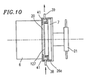
- FIG. 10 is a cross-sectional view of a second element cooling device 26 a . It should be noted that FIG. 10 illustrates the color separation/color combining prism 6 , the image display element 7 b and the first cooling device 21 as well.
- the second element cooling device 26 a can be used instead of the second element cooling device 26 shown in FIGS. 9A and 9B .
- the second element cooling device 26 a is joined to the image display element 7 b .
- the second element cooling device 26 a has a configuration in which a space between the color separation/color combining prism 6 and the display surface 127 of the image display element 7 b is filled with the liquid refrigerant 20 .
- the element cooling device 26 a As a material of the element cooling device 26 a , aluminum or the like, which have good thermal conductivity, can be used. Alternatively, a portion 41 of the second element cooling device 26 a , which is in contact with the color separation/color combining prism 6 , can be made of an elastic material (e.g., elastic rubber). This enables adjustments of a positional relationship between the color separation/color combining prism 6 and the image display element 7 b while preventing leakage of the liquid refrigerant 20 .
- an elastic material e.g., elastic rubber
- a portion of the second element cooling device 26 a which is in contact with the display surface 127 of the image display element 7 b (or a portion which is in contact with the circumference of the display surface 127 of the image display element 7 b ), can be made of an elastic material.
- the second element cooling device 26 a has a function of also cooling the color separation/color combining prism 6 using the liquid refrigerant 20 while cooling the display surface 127 of the image display element 7 b.
- the liquid refrigerant 20 is optically coupled to the display surface 127 and the color separation/color combining prism 6 .
- a mixed liquid of ethylene glycol (55%), diethylene glycol (30%) and glycerin (15%) can be preferably used as the liquid refrigerant 20 .
- a space between the image display element 7 b and the color separation/color combining prism 6 is filled with the liquid refrigerant 20 . Therefore, quality of an image projected onto the screen 110 is not deteriorated by dust in the air adhering to the surface of the color separation/color combining prism 6 and/or the display surface 127 of the image display element 7 b.
- the image display element 7 b is cooled by both the first and second element cooling devices 21 and 26 using the liquid refrigerant. Since thermal conductivity of the liquid refrigerant 20 is considerably high as compared to thermal conductivity of the air, the image display element 7 b can be efficiently cooled.
- vibrations of a cooling fan is not conducted to the image display element 7 b , and thus quality of the image projected onto the screen 110 is not deteriorated.
- the extraneous light 10 a from the image display element 7 b is absorbed in the prism cooling device 19 (an absorption section).
- the prism cooling device 19 can be efficiently cooled by the liquid refrigerant 20 .
- the prism cooling device 19 also functions as a cooling section for efficiently cooling the color separation/color combining prism 6 by the liquid refrigerant 20 .
- FIG. 2 shows an example in which the prism cooling device 19 and the first and second element cooling devices 21 and 26 are connected to one another via a common one-system circulation path.
- a separate circulation path can be provided to each of the prism cooling device 19 and the first and second element cooling devices 21 and 26 .
- a liquid refrigerant used in the respective circulation paths for the first and second element cooling devices 21 and 26 is not necessarily transparent. This is because the liquid refrigerants used in these circulation paths are not required to be optically coupled to the color separation/color combining prism 6 or the display surface 127 of the image display element 7 b.
- the prism cooling device 19 and the first and second element cooling devices 21 and 26 are provided to the projection-type imaging device 1000 .
- Any one of the prism cooling device 19 and the first and second element cooling devices 21 and 26 can be solely used.
- a combination of the prism cooling device 19 according to the embodiment of the present invention and the conventional image display element 7 b can be used.
- the image display element 7 b is not necessarily a micromirror-type image display element. Any reflection-type image display element can be used as the image display element 7 b .
- the prism cooling device 19 does not function as the absorption section for absorbing the extraneous light 10 a . This is because the extraneous light 10 a is not created in such a case.
- the prism cooling device 19 can function as a cooling section for cooling a prism (color separation/color combining prism 6 ) by the liquid refrigerant 20 . In this case, the liquid refrigerant 20 is not necessarily transparent.
- the inventors of the present invention carried out an experiment for measuring cooling performance data (temperature data) for the purpose of verifying a cooling effect of the cooling structure 1010 according to the above-described embodiment of the present invention shown in FIG. 2 .
- FIG. 11 shows cooling performance data for the cooling structure 1010 ( FIG. 2 ) according to the embodiment of the present invention.
- the horizontal axis denotes time elapsed since the start of the experiment
- the vertical axis denotes temperature.
- a thin line, reference numeral 1101 represents the temperature over time at a back face side of one of the image display elements 7 a – 7 c ( FIG. 1 )
- a bold line, reference numeral 1102 represents the temperature over time at a display surface side of the image display element.
- FIG. 11 also shows a room temperature (thin line, reference numeral 1103 ) in the environment under which the experiment was carried out.
- the liquid refrigerant 20 is circulated by pump 22 ( FIG. 2 ) via the prism cooling device 19 and the first and second element cooling devices 21 and 26 and heat is radiated into the ambient air by the radiator 24 .
- the experimental conditions were as follows.
- the experiment is carried out by controlling the circulation of the liquid refrigerant 20 .
- the liquid refrigerants 20 is circulated through the prism cooling device 19 , and the first and second element cooling devices 21 and 26 .
- circulation of the liquid refrigerant 20 enhances the cooling effect. Furthermore, it is appreciated that a temperature of the image display element is stabilized by circulating the liquid refrigerant 20 through both the first and second element cooling devices 21 and 26 .
- the image display element can be efficiently cooled.
- FIG. 12 illustrates a cooling structure 1020 according to a variation of the embodiment of the present invention.
- the cooling structure 1020 can be used in the projection-type imaging device 1000 ( FIG. 1 ) instead of the cooling structure 1010 ( FIG. 2 ).
- the cooling structure 1020 is different from the cooling structure 1010 in that transparent glass 42 is provided between the prism cooling device 19 and the color separation/color combining prism 6 and an air chamber 43 is provided so as to be connected to the pipeline tube 23 .
- the transparent glass 42 is joined to the top face of the color separation/color combining prism 6 by a transparent adhesive 1201 .
- the color separation/color combining prism 6 includes three prisms 6 a – 6 c . Therefore, there are slight differences in levels between the three prisms 6 a – 6 c .
- the transparent glass 42 By providing the transparent glass 42 on the top face of the color separation/color combining prism 6 , even if there are slight differences in level on the surface, the junction of the prism cooling device 19 and the color separation/color combining prism 6 are facilitated.
- the liquid refrigerant 20 is optically coupled to the color separation/color combining prism 6 via the transparent glass 42 and the transparent adhesive 1201 .
- the extraneous light 10 a can be guided through the liquid refrigerant 20 to the prism cooling device 19 (an absorption section).
- the air chamber 43 is a device for trapping the air (air bubbles) coming into the circulation path of the liquid refrigerant 20 and storing it. When air comes into the circulation path, it becomes difficult to flow the liquid refrigerant 20 or heat exchange efficiency will be reduced.
- the air chamber 43 can be provided as a liquid collection section used for replacement or replenishment of the liquid refrigerant 20 .
- FIG. 13A is a cross-sectional view showing an example of a configuration of the air chamber 43 .
- the air chamber 43 is a liquid container having a box-like shape.
- the liquid refrigerant 20 is injected from a refrigerant inlet 44 , stored in the container of the air chamber 43 , and is guided from a refrigerant outlet 45 into the radiator 24 ( FIG. 12 ).
- FIG. 13A shows a state of the liquid refrigerant 20 in the case where the projection-type imaging device 1000 ( FIG. 1 ) is positioned on a horizontal plane.
- the air 46 stays in an upper part of the air chamber 43 due to buoyancy thereof. Since the refrigerant outlet 45 is positioned at about the middle of the air chamber 43 in a height direction (in a top to bottom direction in FIG. 13A ), the air 46 does not come out from the refrigerant outlet 45 (i.e., the air 46 is not reintroduced into the circulation path of the liquid refrigerant 20 ). Even if the air chamber 43 is placed upside down from the state shown in FIG. 13A , it is apparent that the same effect can be achieved.
- FIG. 13B shows a state of the liquid refrigerant 20 in the case where the air chamber 43 is positioned in a slanted manner. Such a state can be provided, for example, when the projection-type imaging device 1000 is placed on an inclined plane. In the state shown in FIG. 13B , the air 46 also stays in the upper part of the air chamber 43 (a direction opposite to that along which gravity works).
- FIG. 14A is a cross-sectional view showing an example of a configuration of an air chamber 43 a .
- the air chamber 43 a can be used in the cooling structure 1020 ( FIG. 12 ) instead of the air chamber 43 shown in FIGS. 13A and 13B .
- the air chamber 43 a has a cylindrical shape.
- An air stopper 48 is fixed in the air chamber 43 a by a support member (not shown).
- the liquid refrigerant 20 flows from the refrigerant inlet 44 as indicated by an arrow.
- the air 46 hits the air stopper 48 and then moves so as to stay in an upper part of an air chamber 47 due to buoyancy thereof. Therefore, the air 46 does not come out from the refrigerant outlet 45 (i.e., the air 46 is not reintroduced into the circulation path of the liquid refrigerant 20 ).
- FIG. 14B shows a state of the air chamber 43 a placed in a manner differing from the manner shown in FIG. 14A .
- the underside in FIG. 14B corresponds to the left side in FIG. 14A .
- the liquid refrigerant 20 flows from the refrigerant inlet 44 as indicated by an arrow.
- the air 46 hits the air stopper 48 and then moves so as to stay in a protrusion portion 49 of the air chamber 47 due to buoyancy thereof. Therefore, the air 46 does not come out from the refrigerant outlet 45 (i.e., the air 46 is not reintroduced into the circulation path of the liquid refrigerant 20 ).
- the air 46 can be prevented from coming into the circulation path of the liquid refrigerant 20 regardless of the installation direction of the projection-type imaging device 1000 . Therefore, satisfactory flow of the liquid refrigerant 20 is secured and heat exchange efficiency can be prevented from being reduced.
- the air chamber 43 can be provided between the radiator 24 and the pump 22 .
- the air chamber 43 is preferably provided before (at an upstream side of) the pump 22 .
- FIG. 15 shows a cooling structure 1030 according to a variation of the embodiment of the present invention.
- the cooling structure 1030 can be used in the projection-type imaging device 1000 ( FIG. 1 ) of the present invention instead of the cooling structure 1010 ( FIG. 2 ).
- the cooling structure 1030 is different from the cooling structure 1010 in that the liquid refrigerant in the prism cooling device is not circulated and the cooling fan 25 is controlled according to a temperature in the vicinity of the image display element 7 b.
- a prism cooling device 19 a is provided instead of the prism cooling device 19 of the cooling structure 1010 .
- the prism cooling device 19 a is filled with a liquid refrigerant 20 a . Since the prism cooling device 19 a is not connected to the pipeline tube 23 , the liquid refrigerant 20 a is not circulated.
- a prism heat sink (fins) 50 is formed on a top face of the prism cooling device 19 a as a radiator for radiating heat from the liquid refrigerant 20 a into the ambient air.
- a heat sink fan 51 is further placed on top of the prism heat sink 50 .
- the heat sink fan 51 has a function of enhancing heat radiation efficiency by stirring the air around the prism heat sink 50 .
- the liquid refrigerant 20 a is transparent and is optically coupled to the color separation/color combining prism 6 . Therefore, the prism cooling device 19 a can function as an absorption section for absorbing the extraneous light 10 . Furthermore, the prism cooling device 19 a function as a cooling section for cooling the absorption section by the refrigerant 20 a and also functions as a cooling section for cooling the color separation/color combining prism 6 by the liquid refrigerant 20 a.
- the extraneous light 10 a is not created when the image display element 7 b is not a micromirror-type image display element, and thus the prism cooling device 19 a does not function as an absorption section for absorbing the extraneous light 10 a .
- the prism cooling device 19 a still functions as the cooling section for cooling the color separation/color combining prism 6 by the liquid refrigerant 20 a.
- the liquid refrigerant having an index of refraction which is completely equal to an index of refraction of the glass has high viscosity. Therefore, in order to circulate the liquid refrigerant, a high powered pump is required.
- the liquid refrigerant 20 a is not required to be circulated. Therefore, in the cooling structure 1030 , the liquid refrigerant 20 a having an index of refraction which is completely equal to an index of refraction of the glass can be used without enhancing performance of the pump 22 so as to circulate the liquid refrigerant having high viscosity.
- Temperature detectors 52 and 56 respectively detect a temperature in the vicinity of the image display element 7 b and a temperature around the projection-type imaging device 1000 . Output from the temperature detectors 52 and 56 are input to a control circuit 53 .
- the control circuit 53 instructs a drive circuit 54 , based on the temperature in the vicinity of the image display element 7 b and the temperature around the projection-type imaging device 1000 , by means of a signal representing a suitable flow rate of the liquid refrigerant 20 and a signal representing whether or not the cooling fan 25 should be operated.
- the drive circuit 54 drives the pump 22 based on these signals.
- the quantity (SI unit system) of heat exchanged between the liquid refrigerant 20 and a surface (e.g., an inner surface of the radiator 24 ) which is in contact with the liquid refrigerant 20 is given by (Expression 1).
- Q V* ⁇ *Cp* ⁇ T (Expression 1), where
- V a flow rate of the liquid refrigerant 20 [m 3 /s]
- ⁇ T a temperature difference (° C.).
- the quantity of heat to be exchanged depends on flow rate V of the liquid refrigerant 20 .
- a circulation flow rate of the liquid refrigerant 20 is variably controlled according to an ambient temperature. For example, when the ambient temperature is low, the circulation flow rate of the liquid refrigerant 20 is controlled so as to be low, and when the ambient temperature is high, the circulation flow rate of the liquid refrigerant 20 is controlled so as to be high. This allows the temperatures of the reflection-type image display element 7 and/or the color separation/color combining prism 6 to be optimally controlled.
- whether the cooling fan 25 is operated or stopped can be controlled according to the ambient temperature.
- the ambient temperature is low, the number of rotations of each of the cooling fan 25 and pump 22 can be lowered, thereby lowering the noise of the projection-type imaging device 1000 .
- the inventors of the present invention carried out an experiment for measuring cooling performance data (temperature data) for the purpose of verifying effectiveness of the prism heat sink 50 and heat sink fan 51 of the cooling structure 1030 according to the embodiment of the present invention shown in FIG. 15 .
- FIG. 16 shows cooling performance data for the prism heat sink 50 and the heat sink fan 51 both shown in FIG. 15 .
- This experiment was carried out on the cooling structure 1020 shown in FIG. 12 in which the prism heat sink 50 and the heat sink fan 51 are placed on the prism cooling device 19 .
- the horizontal axis denotes elapsed time and the vertical axis denotes temperature.
- a thin line reference numeral 1610 represents the temperature overtime at the top of the color separation/color combining prism 6
- a bold line reference numeral 1611 represents the temperature overtime at the top of the prism cooling device 19 .
- the experimental conditions were as follows.
- the xenon lamp 101 ( FIG. 1 ) was lit up (time point 1601 ) in the state where the prism heat sink 50 and the heat sink fan 51 were not placed on the prism cooling device 19 and the liquid refrigerant 20 was not circulated. In this state, the temperature 1610 at the top of the color separation/color combining prism 6 and the temperature 1611 at the top of the prism cooling device 19 were rapidly increased (period 1602 ). At a time point 1603 , in order to prevent breakage of the projection-type imaging device, the xenon lamp 101 was turned off and the projection-type imaging device was naturally cooled.
- the xenon lamp 101 was lit up with the prism heat sink 50 and the heat sink fan 51 placed on the prism cooling device 19 , and the heat sink fan 51 was operated. At this point, the liquid refrigerant 20 was not circulated.
- the heat sink fan 51 was operated. It is appreciated that the operation of the heat sink fan 51 causes rapid reduction in the temperature 1610 at the top of the color separation/color combining prism 6 and the temperature 1611 at the top of the prism cooling device 19 .
- the image display elements 7 a – 7 c and the color separation/color combining prism 6 can be efficiently cooled, and no problem is caused by enhancing optical output of the light source lamp unit 1 .
- a cooling structure of a projection-type imaging device can be formed by suitably combining components shown in the different drawings.
- providing the air chamber 43 shown in FIG. 12 to the cooling structure 1010 ( FIG. 2 ) or the cooling structure 1030 ( FIG. 15 ) or providing the temperature detectors 52 and 56 , the control circuit 53 and the drive circuit 54 shown in FIG. 15 to the cooling structure 1010 ( FIG. 2 ) or the cooling structure 1020 ( FIG. 12 ) are within the scope of the present invention.
- the projection-type imaging device of the present invention includes the absorption section for absorbing extraneous light (second light) which is reflected by the display surface of the micromirror-type image display element and is transmitted by the prism.
- This absorption section is cooled by the liquid refrigerant. Since the liquid refrigerant has high cooling effectiveness as compared to air, the absorption section can be efficiently cooled.
- the prism does not require a configuration for guiding the extraneous light to the absorption section, and thus the prism can be made compact.
- the projection-type imaging device of the present invention includes the cooling section for cooling the prism, which transmits information light reflected by the display surface of the reflection-type image display element, by the liquid refrigerant. Since the liquid refrigerant has high cooling effectiveness as compared to air, the prism can be efficiently cooled.
- the projection-type imaging device of the present invention includes the cooling section for cooling a surface of the reflection-type image display element opposed to the display surface by the liquid refrigerant. Since the liquid refrigerant has high cooling effectiveness as compared to air, the image display element can be efficiently cooled.
Landscapes
- Physics & Mathematics (AREA)
- General Physics & Mathematics (AREA)
- Optics & Photonics (AREA)
- Engineering & Computer Science (AREA)
- Multimedia (AREA)
- Signal Processing (AREA)
- Projection Apparatus (AREA)
Abstract
Description
-
- The liquid refrigerant 20: a water solution of ethylene glycol
- Circulation flow rate: 40–66 cc/min.
- Optical output from the light source lamp unit 1 (
FIG. 1 ): 6000 ANSI lumen-hours
Q=V*ρ*Cp*ΔT (Expression 1),
where
-
- Liquid refrigerant 20: a water solution of ethylene glycol
- Circulation flow rate: about 100 cc/min.
- Optical output of the light source lamp unit 1 (
FIG. 1 ): 3000 ANSI lumen-hours
Claims (27)
Applications Claiming Priority (3)
| Application Number | Priority Date | Filing Date | Title |
|---|---|---|---|
| JP2000256916 | 2000-08-28 | ||
| JP2000-256916 | 2000-08-28 | ||
| PCT/JP2001/007342 WO2002019027A1 (en) | 2000-08-28 | 2001-08-27 | Projection video device |
Publications (2)
| Publication Number | Publication Date |
|---|---|
| US20020163625A1 US20020163625A1 (en) | 2002-11-07 |
| US7084931B2 true US7084931B2 (en) | 2006-08-01 |
Family
ID=36794816
Family Applications (1)
| Application Number | Title | Priority Date | Filing Date |
|---|---|---|---|
| US10/111,763 Expired - Fee Related US7084931B2 (en) | 2000-08-28 | 2001-08-27 | Projection video device |
Country Status (1)
| Country | Link |
|---|---|
| US (1) | US7084931B2 (en) |
Cited By (8)
| Publication number | Priority date | Publication date | Assignee | Title |
|---|---|---|---|---|
| US20050173097A1 (en) * | 2004-02-10 | 2005-08-11 | Hitachi Cable, Ltd. | Liquid circulation type cooling system |
| US20060290893A1 (en) * | 2005-04-21 | 2006-12-28 | Seon-Woo Lim | Image projection apparatus and method of cooling an image projection apparatus |
| US20070024814A1 (en) * | 2005-07-26 | 2007-02-01 | Samsung Electronics Co., Ltd. | Image projecting apparatus |
| US20070164925A1 (en) * | 2005-10-21 | 2007-07-19 | Samsung Electronics Co., Ltd. | Projection system and control method of the same |
| US20080043439A1 (en) * | 2006-08-21 | 2008-02-21 | Delta Electronics, Inc. | Cooling module for use with a projection apparatus |
| CN102089707B (en) * | 2008-03-26 | 2012-07-18 | 日本电气株式会社 | Projector |
| US20160349604A1 (en) * | 2015-05-26 | 2016-12-01 | Panasonic Intellectual Property Management Co., Ltd. | Projection image display apparatus |
| US11493839B2 (en) * | 2020-07-30 | 2022-11-08 | Panasonic Intellectual Property Management Co., Ltd. | Projection image display device |
Families Citing this family (22)
| Publication number | Priority date | Publication date | Assignee | Title |
|---|---|---|---|---|
| WO2003086955A1 (en) * | 2002-04-12 | 2003-10-23 | Fraunhofer-Gesellschaft zur Förderung der angewandten Forschung e.V. | Method and device for operating a micromechanical element |
| JP2005078966A (en) * | 2003-09-01 | 2005-03-24 | Seiko Epson Corp | LIGHT SOURCE DEVICE, LIGHT SOURCE DEVICE MANUFACTURING METHOD, PROJECTION TYPE DISPLAY DEVICE |
| JP4192882B2 (en) * | 2003-12-26 | 2008-12-10 | セイコーエプソン株式会社 | Optical device and projector |
| US7270418B2 (en) * | 2003-12-26 | 2007-09-18 | Seiko Epson Corporation | Optical device and projector |
| US7384152B2 (en) * | 2004-04-22 | 2008-06-10 | Nec Viewtechnology, Ltd. | Liquid-cooled projector |
| KR100802725B1 (en) * | 2004-06-30 | 2008-02-12 | 가부시키가이샤 히타치세이사쿠쇼 | LCD projectors and their liquid crystal panels and liquid cooling devices |
| JP4056504B2 (en) | 2004-08-18 | 2008-03-05 | Necディスプレイソリューションズ株式会社 | COOLING DEVICE AND ELECTRONIC DEVICE HAVING THE SAME |
| JP4161976B2 (en) * | 2004-11-04 | 2008-10-08 | セイコーエプソン株式会社 | Optical apparatus and projector |
| JP4140610B2 (en) * | 2005-03-01 | 2008-08-27 | セイコーエプソン株式会社 | Optical device and projector |
| EP1863297B1 (en) | 2006-06-02 | 2013-11-20 | Barco NV | Cooling of reflective spatial light modulating devices |
| EP1863296A1 (en) * | 2006-06-02 | 2007-12-05 | Barco NV | Cooling of reflective spatial light modulating devices |
| US8052289B2 (en) * | 2006-06-07 | 2011-11-08 | Asml Netherlands B.V. | Mirror array for lithography |
| US20080174745A1 (en) * | 2007-01-18 | 2008-07-24 | Raytheon Company | Digital light projector with improved contrast |
| JP2008209888A (en) * | 2007-01-31 | 2008-09-11 | Sony Corp | Optical device and projection type display device |
| GB0711641D0 (en) * | 2007-06-18 | 2007-07-25 | Barco Nv | Dual TIR prism architecture to enhance DLP projectors |
| TWI559072B (en) * | 2015-04-15 | 2016-11-21 | 中強光電股份有限公司 | Projector and optical engine module |
| DE102015121402A1 (en) * | 2015-12-09 | 2017-06-14 | Carl Zeiss Smart Optics Gmbh | Device for coupling an image into an optical system |
| US9971147B2 (en) * | 2016-09-26 | 2018-05-15 | Xerox Corporation | Integrated micro-channel heatsink in DMD substrate for enhanced cooling capacity |
| US10018802B1 (en) * | 2017-03-06 | 2018-07-10 | Xerox Corporation | Cooling a digital micromirror device |
| WO2019020198A1 (en) | 2017-07-28 | 2019-01-31 | Barco N.V. | Spatial light modulating devices with cooling |
| JP7140575B2 (en) * | 2018-07-12 | 2022-09-21 | キヤノン株式会社 | Color separation/synthesis system and image projection device provided with the same |
| JP2020017476A (en) * | 2018-07-27 | 2020-01-30 | 株式会社島津製作所 | Light source device |
Citations (16)
| Publication number | Priority date | Publication date | Assignee | Title |
|---|---|---|---|---|
| JPH05232432A (en) | 1992-02-24 | 1993-09-10 | Sanyo Electric Co Ltd | Cooler for liquid crystal projector |
| JPH05264947A (en) | 1992-03-17 | 1993-10-15 | Fujitsu General Ltd | Cooling device of projecting device |
| JPH0996867A (en) | 1995-09-28 | 1997-04-08 | Fuji Photo Optical Co Ltd | Optical system for video projector |
| US5633691A (en) * | 1995-06-07 | 1997-05-27 | Nview Corporation | Stylus position sensing and digital camera with a digital micromirror device |
| US5758956A (en) * | 1991-04-30 | 1998-06-02 | Vari-Lite, Inc. | High intensity lighting projectors |
| US5946054A (en) * | 1995-09-07 | 1999-08-31 | Matsushita Electric Industrial Co., Ltd. | Optical apparatus, projection display apparatus and optical compensation method |
| JPH11282361A (en) | 1998-03-27 | 1999-10-15 | Mitsubishi Electric Corp | Image display unit |
| JP2000206451A (en) | 1999-01-18 | 2000-07-28 | Minolta Co Ltd | Optical system for projector |
| US6219111B1 (en) * | 1997-09-30 | 2001-04-17 | Sony Corporation | Projection-type liquid crystal display apparatus |
| US6290360B1 (en) * | 1997-11-20 | 2001-09-18 | Hitachi, Ltd. | Liquid crystal projector, and projection lens unit, optical unit and cooling system for the same |
| US6309074B1 (en) * | 1995-06-21 | 2001-10-30 | Smartlight Ltd. | Backprojection transparency viewer |
| US6345896B1 (en) * | 1999-02-19 | 2002-02-12 | Seiko Epson Corporation | Projector capable of easily replacing and efficiently cooling light source |
| US6456341B1 (en) * | 1999-03-31 | 2002-09-24 | Samsung Electronics Co., Ltd. | CRT assembly of projection TV system |
| US6478429B1 (en) * | 1998-10-29 | 2002-11-12 | Fujitsu Limited | Reflective projector |
| US6568813B1 (en) * | 1999-04-23 | 2003-05-27 | Seiko Epson Corporation | Projector having an upper cooling fan |
| US6573950B1 (en) * | 1999-01-21 | 2003-06-03 | Hitachi, Ltd. | Optical projection apparatus, transmission type screen, and projection type image display apparatus |
-
2001
- 2001-08-27 US US10/111,763 patent/US7084931B2/en not_active Expired - Fee Related
Patent Citations (17)
| Publication number | Priority date | Publication date | Assignee | Title |
|---|---|---|---|---|
| US5758956A (en) * | 1991-04-30 | 1998-06-02 | Vari-Lite, Inc. | High intensity lighting projectors |
| JPH05232432A (en) | 1992-02-24 | 1993-09-10 | Sanyo Electric Co Ltd | Cooler for liquid crystal projector |
| JPH05264947A (en) | 1992-03-17 | 1993-10-15 | Fujitsu General Ltd | Cooling device of projecting device |
| US5633691A (en) * | 1995-06-07 | 1997-05-27 | Nview Corporation | Stylus position sensing and digital camera with a digital micromirror device |
| US6309074B1 (en) * | 1995-06-21 | 2001-10-30 | Smartlight Ltd. | Backprojection transparency viewer |
| US5946054A (en) * | 1995-09-07 | 1999-08-31 | Matsushita Electric Industrial Co., Ltd. | Optical apparatus, projection display apparatus and optical compensation method |
| JPH0996867A (en) | 1995-09-28 | 1997-04-08 | Fuji Photo Optical Co Ltd | Optical system for video projector |
| US6219111B1 (en) * | 1997-09-30 | 2001-04-17 | Sony Corporation | Projection-type liquid crystal display apparatus |
| US6290360B1 (en) * | 1997-11-20 | 2001-09-18 | Hitachi, Ltd. | Liquid crystal projector, and projection lens unit, optical unit and cooling system for the same |
| US6783245B2 (en) * | 1997-11-20 | 2004-08-31 | Hitachi Ltd. | Liquid crystal projector, and projection lens unit, optical unit and cooling system for the same |
| JPH11282361A (en) | 1998-03-27 | 1999-10-15 | Mitsubishi Electric Corp | Image display unit |
| US6478429B1 (en) * | 1998-10-29 | 2002-11-12 | Fujitsu Limited | Reflective projector |
| JP2000206451A (en) | 1999-01-18 | 2000-07-28 | Minolta Co Ltd | Optical system for projector |
| US6573950B1 (en) * | 1999-01-21 | 2003-06-03 | Hitachi, Ltd. | Optical projection apparatus, transmission type screen, and projection type image display apparatus |
| US6345896B1 (en) * | 1999-02-19 | 2002-02-12 | Seiko Epson Corporation | Projector capable of easily replacing and efficiently cooling light source |
| US6456341B1 (en) * | 1999-03-31 | 2002-09-24 | Samsung Electronics Co., Ltd. | CRT assembly of projection TV system |
| US6568813B1 (en) * | 1999-04-23 | 2003-05-27 | Seiko Epson Corporation | Projector having an upper cooling fan |
Cited By (10)
| Publication number | Priority date | Publication date | Assignee | Title |
|---|---|---|---|---|
| US20050173097A1 (en) * | 2004-02-10 | 2005-08-11 | Hitachi Cable, Ltd. | Liquid circulation type cooling system |
| US20060290893A1 (en) * | 2005-04-21 | 2006-12-28 | Seon-Woo Lim | Image projection apparatus and method of cooling an image projection apparatus |
| US8256901B2 (en) | 2005-04-21 | 2012-09-04 | Samsung Electronics Co., Ltd. | Image projection apparatus and method of cooling an image projection apparatus |
| US20070024814A1 (en) * | 2005-07-26 | 2007-02-01 | Samsung Electronics Co., Ltd. | Image projecting apparatus |
| US20070164925A1 (en) * | 2005-10-21 | 2007-07-19 | Samsung Electronics Co., Ltd. | Projection system and control method of the same |
| US20080043439A1 (en) * | 2006-08-21 | 2008-02-21 | Delta Electronics, Inc. | Cooling module for use with a projection apparatus |
| US8147072B2 (en) * | 2006-08-21 | 2012-04-03 | Delta Electronics, Inc. | Cooling module for use with a projection apparatus |
| CN102089707B (en) * | 2008-03-26 | 2012-07-18 | 日本电气株式会社 | Projector |
| US20160349604A1 (en) * | 2015-05-26 | 2016-12-01 | Panasonic Intellectual Property Management Co., Ltd. | Projection image display apparatus |
| US11493839B2 (en) * | 2020-07-30 | 2022-11-08 | Panasonic Intellectual Property Management Co., Ltd. | Projection image display device |
Also Published As
| Publication number | Publication date |
|---|---|
| US20020163625A1 (en) | 2002-11-07 |
Similar Documents
| Publication | Publication Date | Title |
|---|---|---|
| US7084931B2 (en) | Projection video device | |
| EP1315028B1 (en) | Projection video device | |
| US6582083B2 (en) | Display device and display optical system unit | |
| JP3608428B2 (en) | Projection display | |
| US20060203206A1 (en) | Cooling apparatus and a projector having the same | |
| JP2012181386A (en) | Reflection type optical element cooling device and reflection type optical element unit | |
| CN109634031B (en) | Full-sealed liquid crystal projection optical machine device with efficient heat dissipation function | |
| JP2008176079A (en) | Cooling device | |
| JP2005121250A (en) | Cooling device and rear projector | |
| JP3414341B2 (en) | projector | |
| JP2002006282A (en) | Liquid crystal display device | |
| JP2018205462A (en) | projector | |
| CN106054505A (en) | Projector | |
| JP2005121712A (en) | projector | |
| JP2006208488A (en) | Rear projector | |
| JP2006098759A (en) | Liquid crystal projector and liquid-cooling apparatus for the same | |
| JP3267279B2 (en) | Display device | |
| JP2012198402A (en) | Projector | |
| JP2003195253A (en) | Optical device and projector having the same | |
| JP2005114997A (en) | Optical device and rear projector | |
| JP5938929B2 (en) | projector | |
| JP7394586B2 (en) | image projection device | |
| JP2007025384A (en) | Light modulation device, optical device, and projector | |
| JP3506109B2 (en) | projector | |
| JP2005208632A (en) | Light modulation element holder, optical device, and projector |
Legal Events
| Date | Code | Title | Description |
|---|---|---|---|
| AS | Assignment |
Owner name: MATSUSHITA ELECTRIC INDUSTRIAL CO., LTD., JAPAN Free format text: ASSIGNMENT OF ASSIGNORS INTEREST;ASSIGNORS:TABUCHI, TOSHIAKI;SANNOHE, SHINYA;REEL/FRAME:013092/0128 Effective date: 20020405 |
|
| FEPP | Fee payment procedure |
Free format text: PAYOR NUMBER ASSIGNED (ORIGINAL EVENT CODE: ASPN); ENTITY STATUS OF PATENT OWNER: LARGE ENTITY |
|
| FPAY | Fee payment |
Year of fee payment: 4 |
|
| FPAY | Fee payment |
Year of fee payment: 8 |
|
| FEPP | Fee payment procedure |
Free format text: MAINTENANCE FEE REMINDER MAILED (ORIGINAL EVENT CODE: REM.) |
|
| LAPS | Lapse for failure to pay maintenance fees |
Free format text: PATENT EXPIRED FOR FAILURE TO PAY MAINTENANCE FEES (ORIGINAL EVENT CODE: EXP.); ENTITY STATUS OF PATENT OWNER: LARGE ENTITY |
|
| STCH | Information on status: patent discontinuation |
Free format text: PATENT EXPIRED DUE TO NONPAYMENT OF MAINTENANCE FEES UNDER 37 CFR 1.362 |
|
| FP | Lapsed due to failure to pay maintenance fee |
Effective date: 20180801 |