JP2005208632A - Light modulation element holder, optical device, and projector - Google Patents
Light modulation element holder, optical device, and projector Download PDFInfo
- Publication number
- JP2005208632A JP2005208632A JP2004376800A JP2004376800A JP2005208632A JP 2005208632 A JP2005208632 A JP 2005208632A JP 2004376800 A JP2004376800 A JP 2004376800A JP 2004376800 A JP2004376800 A JP 2004376800A JP 2005208632 A JP2005208632 A JP 2005208632A
- Authority
- JP
- Japan
- Prior art keywords
- light modulation
- cooling fluid
- modulation element
- light
- optical device
- Prior art date
- Legal status (The legal status is an assumption and is not a legal conclusion. Google has not performed a legal analysis and makes no representation as to the accuracy of the status listed.)
- Withdrawn
Links
- 230000003287 optical effect Effects 0.000 title claims abstract description 252
- 239000012809 cooling fluid Substances 0.000 claims abstract description 339
- 238000001816 cooling Methods 0.000 claims abstract description 148
- 239000000758 substrate Substances 0.000 claims abstract description 54
- 239000012530 fluid Substances 0.000 claims description 155
- 230000010287 polarization Effects 0.000 claims description 36
- 238000003860 storage Methods 0.000 claims description 19
- 238000009825 accumulation Methods 0.000 claims description 17
- 230000015572 biosynthetic process Effects 0.000 claims description 15
- 238000003786 synthesis reaction Methods 0.000 claims description 13
- 239000004020 conductor Substances 0.000 claims description 12
- 230000002194 synthesizing effect Effects 0.000 claims description 12
- 238000011144 upstream manufacturing Methods 0.000 claims description 12
- 238000012546 transfer Methods 0.000 claims description 11
- 230000008859 change Effects 0.000 claims description 7
- 230000004907 flux Effects 0.000 claims description 7
- 230000005540 biological transmission Effects 0.000 claims description 4
- 230000020169 heat generation Effects 0.000 claims description 4
- 239000004973 liquid crystal related substance Substances 0.000 abstract description 114
- 239000000463 material Substances 0.000 description 13
- 229910052782 aluminium Inorganic materials 0.000 description 12
- XAGFODPZIPBFFR-UHFFFAOYSA-N aluminium Chemical compound [Al] XAGFODPZIPBFFR-UHFFFAOYSA-N 0.000 description 12
- 125000006850 spacer group Chemical group 0.000 description 12
- 238000006243 chemical reaction Methods 0.000 description 9
- LYCAIKOWRPUZTN-UHFFFAOYSA-N Ethylene glycol Chemical compound OCCO LYCAIKOWRPUZTN-UHFFFAOYSA-N 0.000 description 6
- 238000005286 illumination Methods 0.000 description 6
- 238000010586 diagram Methods 0.000 description 5
- 239000011521 glass Substances 0.000 description 5
- 229910010272 inorganic material Inorganic materials 0.000 description 4
- 239000011147 inorganic material Substances 0.000 description 4
- 239000011159 matrix material Substances 0.000 description 4
- 229910052751 metal Inorganic materials 0.000 description 4
- 239000002184 metal Substances 0.000 description 4
- 238000002156 mixing Methods 0.000 description 4
- 238000000926 separation method Methods 0.000 description 4
- 230000006866 deterioration Effects 0.000 description 3
- 229920000642 polymer Polymers 0.000 description 3
- YCKRFDGAMUMZLT-UHFFFAOYSA-N Fluorine atom Chemical compound [F] YCKRFDGAMUMZLT-UHFFFAOYSA-N 0.000 description 2
- XEEYBQQBJWHFJM-UHFFFAOYSA-N Iron Chemical compound [Fe] XEEYBQQBJWHFJM-UHFFFAOYSA-N 0.000 description 2
- 238000007664 blowing Methods 0.000 description 2
- 229920005549 butyl rubber Polymers 0.000 description 2
- 239000000470 constituent Substances 0.000 description 2
- 238000005260 corrosion Methods 0.000 description 2
- 230000007797 corrosion Effects 0.000 description 2
- 238000009826 distribution Methods 0.000 description 2
- 230000000694 effects Effects 0.000 description 2
- 229920001971 elastomer Polymers 0.000 description 2
- 229910052731 fluorine Inorganic materials 0.000 description 2
- 239000011737 fluorine Substances 0.000 description 2
- 230000017525 heat dissipation Effects 0.000 description 2
- 238000009434 installation Methods 0.000 description 2
- 230000031700 light absorption Effects 0.000 description 2
- 239000007788 liquid Substances 0.000 description 2
- 238000000034 method Methods 0.000 description 2
- 239000011368 organic material Substances 0.000 description 2
- 238000013021 overheating Methods 0.000 description 2
- 230000002093 peripheral effect Effects 0.000 description 2
- 230000008439 repair process Effects 0.000 description 2
- 238000004381 surface treatment Methods 0.000 description 2
- 229920003002 synthetic resin Polymers 0.000 description 2
- 239000000057 synthetic resin Substances 0.000 description 2
- RYGMFSIKBFXOCR-UHFFFAOYSA-N Copper Chemical compound [Cu] RYGMFSIKBFXOCR-UHFFFAOYSA-N 0.000 description 1
- 229910000737 Duralumin Inorganic materials 0.000 description 1
- 235000010724 Wisteria floribunda Nutrition 0.000 description 1
- 238000010521 absorption reaction Methods 0.000 description 1
- 238000004040 coloring Methods 0.000 description 1
- 238000004891 communication Methods 0.000 description 1
- 229910052802 copper Inorganic materials 0.000 description 1
- 239000010949 copper Substances 0.000 description 1
- 238000004132 cross linking Methods 0.000 description 1
- 238000013461 design Methods 0.000 description 1
- 238000007599 discharging Methods 0.000 description 1
- -1 for example Substances 0.000 description 1
- 229910052736 halogen Inorganic materials 0.000 description 1
- 150000002367 halogens Chemical class 0.000 description 1
- 229910052742 iron Inorganic materials 0.000 description 1
- 238000010030 laminating Methods 0.000 description 1
- 239000010410 layer Substances 0.000 description 1
- QSHDDOUJBYECFT-UHFFFAOYSA-N mercury Chemical compound [Hg] QSHDDOUJBYECFT-UHFFFAOYSA-N 0.000 description 1
- 229910052753 mercury Inorganic materials 0.000 description 1
- 229910001507 metal halide Inorganic materials 0.000 description 1
- 150000005309 metal halides Chemical class 0.000 description 1
- 239000007769 metal material Substances 0.000 description 1
- 238000012986 modification Methods 0.000 description 1
- 230000004048 modification Effects 0.000 description 1
- 238000003825 pressing Methods 0.000 description 1
- 230000008569 process Effects 0.000 description 1
- 230000005855 radiation Effects 0.000 description 1
- 230000009467 reduction Effects 0.000 description 1
- 230000000717 retained effect Effects 0.000 description 1
- 238000007789 sealing Methods 0.000 description 1
- 229920002379 silicone rubber Polymers 0.000 description 1
- 239000000126 substance Substances 0.000 description 1
- 239000002344 surface layer Substances 0.000 description 1
Images


Landscapes
- Liquid Crystal (AREA)
- Projection Apparatus (AREA)
Abstract
【課題】 冷却流体により光変調素子を効率的に冷却できる光変調素子保持体、光学装
置、およびプロジェクタを提供する。
【解決手段】光変調素子保持体446は、液晶パネル441の画像形成領域に応じてそれ
ぞれ開口4461A,4462Aが形成され、液晶パネル441を挟持する1対の枠状部
材4461,4462と、枠状部材4462における光束射出側に配置される透光性基板
4464とを含んで構成される。枠状部材4462の光束入射側および光束射出側が液晶
パネル441および透光性基板4464にてそれぞれ閉塞されることにより枠状部材44
62内部に冷却室が形成される。この枠状部材4462は、冷却室に冷却流体を流入させ
る流入口4462Dと、冷却室内部の冷却流体を外部に流出させる流出口4462Eとを
有し、流入口4462D近傍には冷却流体を冷却室内部に拡げるように流入させる整流部
が形成されている。
【選択図】 図6PROBLEM TO BE SOLVED: To provide a light modulation element holder, an optical device, and a projector capable of efficiently cooling a light modulation element with a cooling fluid.
An optical modulation element holding body 446 has openings 4461A and 4462A formed in accordance with an image forming area of a liquid crystal panel 441, respectively, and a pair of frame-like members 4461 and 4462 for sandwiching the liquid crystal panel 441, and a frame shape. And a translucent substrate 4464 arranged on the light beam exit side of the member 4462. The frame-shaped member 4462 is closed by the liquid crystal panel 441 and the light-transmitting substrate 4464 on the light beam incident side and the light beam emission side of the frame-shaped member 4462, respectively.
A cooling chamber is formed inside 62. The frame-like member 4462 has an inlet 4462D for allowing the cooling fluid to flow into the cooling chamber, and an outlet 4462E for allowing the cooling fluid inside the cooling chamber to flow outside, and the cooling fluid is placed near the inlet 4462D in the cooling chamber. A rectifying portion is formed to flow in so as to expand inside.
[Selection] Figure 6
Description
本発明は、光変調素子保持体、光学装置、およびプロジェクタに関する。 The present invention relates to a light modulation element holder, an optical device, and a projector.
従来、光源から射出された光束を画像情報に応じて変調して光学像を形成する複数の光
変調素子と、各光変調素子で変調された光束を合成して射出する色合成光学装置と、色合
成光学装置にて合成された光束を拡大投射する投射光学装置とを備えるプロジェクタが知
られている。
このうち、光変調素子としては、例えば、1対の基板間に液晶等の電気光学材料が密閉
封入されたアクティブマトリックス駆動方式の液晶パネルと、所定の偏光軸を有する光束のみを透過させる偏光板とを備える構成が一般的に採用される。
具体的に、液晶パネルを構成する1対の基板は、光束射出側に配置され、液晶に駆動電圧を印加するためのデータ線、走査線、スイッチング素子、画素電極等が形成された駆動基板と、光束入射側に配置され、共通電極、ブラックマスク等が形成された対向基板とで構成されている。
ここで、光源から射出された光束が液晶パネルに照射された場合には、液晶層による光
吸収とともに、駆動基板に形成されたデータ線および走査線や、対向基板に形成されたブ
ラックマトリックス等による光吸収により、液晶パネルの温度が上昇しやすい。また、光
源から射出された光束、および液晶パネルを透過した光束のうち、所定の偏光軸を有して
いない光束は、入射側偏光板および射出側偏光板によって吸収され、偏光板に熱が発生し
やすい。
Conventionally, a plurality of light modulation elements that form an optical image by modulating a light beam emitted from a light source according to image information, a color combining optical device that combines and emits a light beam modulated by each light modulation element, There is known a projector including a projection optical device that enlarges and projects a light beam synthesized by a color synthesis optical device.
Among these, as the light modulation element, for example, an active matrix driving type liquid crystal panel in which an electro-optical material such as liquid crystal is hermetically sealed between a pair of substrates, and a polarizing plate that transmits only a light beam having a predetermined polarization axis Generally, a configuration including the above is adopted.
Specifically, a pair of substrates constituting the liquid crystal panel is disposed on the light beam emission side, and a driving substrate on which data lines, scanning lines, switching elements, pixel electrodes, and the like for applying a driving voltage to the liquid crystal are formed. The counter substrate is disposed on the light beam incident side and has a common electrode, a black mask and the like formed thereon.
Here, when the light beam emitted from the light source is irradiated onto the liquid crystal panel, the light absorption by the liquid crystal layer, the data lines and scanning lines formed on the driving substrate, the black matrix formed on the counter substrate, and the like The temperature of the liquid crystal panel is likely to rise due to light absorption. Of the luminous flux emitted from the light source and the luminous flux transmitted through the liquid crystal panel, the luminous flux that does not have a predetermined polarization axis is absorbed by the incident-side polarizing plate and the outgoing-side polarizing plate, and heat is generated in the polarizing plate. It's easy to do.
このため、このような光変調素子を内部に有するプロジェクタは、光変調素子の温度上昇を緩和するために、冷却流体を用いた冷却装置を備えた構成が提案されている(例えば、特許文献1参照)。
すなわち、特許文献1に記載の冷却装置は、対向する端面が開口された略直方体状の筐
体から構成され、内部に冷却流体を密閉封入する冷却室を備えている。そして、前記対向
する端面のうち、一方の端面側に液晶パネルを配置し、他方の端面側に偏光板を配置し、これら光変調素子および入射側偏光板にて開口の対向する端面を閉塞し、冷却室を形成している。このような構成により、光源から照射される光束により液晶パネルおよび偏光板に生じる熱を直接、冷却流体に放熱させている。
For this reason, a projector having such a light modulation element inside has been proposed to have a cooling device using a cooling fluid in order to reduce the temperature rise of the light modulation element (for example, Patent Document 1). reference).
That is, the cooling device described in Patent Document 1 is formed of a substantially rectangular parallelepiped casing having opposite end faces opened, and includes a cooling chamber that hermetically encloses a cooling fluid. A liquid crystal panel is disposed on one end face side of the facing end faces, a polarizing plate is disposed on the other end face side, and the facing end faces of the openings are blocked by the light modulation element and the incident side polarizing plate. Forming a cooling chamber. With such a configuration, heat generated in the liquid crystal panel and the polarizing plate by the light beam emitted from the light source is directly radiated to the cooling fluid.
しかしながら、特許文献1に記載の冷却装置では、冷却室内に冷却流体が密閉封入され
るので、発熱した液晶パネルおよび偏光板により冷却流体が温められやすく、温められた冷却流体が冷却室内に滞留してしまう。
したがって、光変調素子と冷却流体との温度差が小さくなり、光変調素子を効率的に冷
却することが困難である、という問題がある。
However, in the cooling device described in Patent Document 1, since the cooling fluid is hermetically sealed in the cooling chamber, the cooling fluid is easily heated by the heated liquid crystal panel and the polarizing plate, and the heated cooling fluid stays in the cooling chamber. End up.
Therefore, there is a problem that the temperature difference between the light modulation element and the cooling fluid becomes small, and it is difficult to efficiently cool the light modulation element.
本発明の目的は、冷却流体により光変調素子を効率的に冷却できる光変調素子保持体、
光学装置、およびプロジェクタを提供することにある。
An object of the present invention is to provide a light modulation element holding body capable of efficiently cooling a light modulation element with a cooling fluid,
An object is to provide an optical device and a projector.
本発明の光変調素子保持体は、光源から射出された光束を画像情報に応じて変調して光
学像を形成する光変調素子を保持し、内部に冷却流体が封入される冷却室が形成され、前
記冷却室内の冷却流体により前記光変調素子を冷却する光変調素子保持体であって、前記
光変調素子の画像形成領域に応じてそれぞれ開口が形成され、前記光変調素子を挟持する
1対の枠状部材と、前記1対の枠状部材における対向する面と反対の面のうち少なくとも
いずれかの面側に配置される透光性基板とを含んで構成され、前記冷却室は、前記1対の
枠状部材の前記開口における前記対向する面側、および前記対向する面と反対の面のうち
少なくともいずれかの面側が前記光変調素子および前記透光性基板にてそれぞれ閉塞され
ることにより前記1対の枠状部材のうち少なくともいずれかの枠状部材の内部に形成され
、前記冷却室が内部に形成される枠状部材は、前記冷却室に前記冷却流体を流入させる流
入口と、前記冷却室内部の前記冷却流体を外部に流出させる流出口とを有し、前記流入口
近傍には、前記冷却流体を前記冷却室内部に拡げるように流入させる整流部が形成されて
いることを特徴とする。
ここで、光変調素子保持体は、透光性基板を1つ有する構成でもよく、2つ有する構成
でもよい。例えば、透光性基板を1つのみ有する構成では、該透光性基板および光変調素
子により1対の枠状部材の開口における対向する面側および対向する面と反対の面のいず
れかの面側がそれぞれ閉塞され、一方の枠状部材の内部にのみ冷却室が形成される。また
、例えば、透光性基板を2つ有する構成では、2つの透光性基板および光変調素子により
1対の枠状部材の開口における対向する面側および対向する面と反対の面がそれぞれ閉塞
され、1対の枠状部材双方の内部にそれぞれ冷却室が形成される。
また、光変調素子としては、例えば、液晶パネルおよび偏光板等の構成を採用できる。光変調素子として、このように液晶パネルおよび偏光板等の構成を採用した場合には、光変調素子保持体は、光変調素子の構成部材の少なくとも1つを保持可能に構成されていればよい。
本発明によれば、冷却室が内部に形成される枠状部材は、流入口および流出口を有する
ので、例えば、冷却流体を流通可能な流体循環部材にて流入口および流出口を接続すれば
、冷却流体を対流させることが容易となり、光変調素子により温められた冷却流体が冷却
室内に滞留することを回避できる。
また、流入口近傍には、整流部が形成され、冷却室内に流入した冷却流体を内部に拡げ
るので、冷却室内全域に亘って冷却流体を対流させることができ、冷却室内に温められた
冷却流体が局所的に滞留することを回避できる。
したがって、光変調素子により冷却流体が温められて光変調素子と冷却流体との温度差
が小さくなることがなく、冷却流体により光変調素子を効率的に冷却でき、本発明の目的
を達成できる。
また、開口が光変調素子の画像形成領域に応じて設けられているので、冷却室に充填さ
れた冷却流体は、光変調素子の画像形成領域に接触する。このことにより、光変調素子の
画像形成領域内の温度分布が均一化され、局所的な過熱を回避し、光変調素子にて鮮明な
光学像を形成できる。
The light modulation element holding body of the present invention holds a light modulation element that forms an optical image by modulating a light beam emitted from a light source according to image information, and a cooling chamber in which a cooling fluid is enclosed is formed. A pair of light modulation element holders that cool the light modulation element with a cooling fluid in the cooling chamber, each having an opening formed in accordance with an image forming region of the light modulation element, and sandwiching the light modulation element And a translucent substrate disposed on at least one of the opposite surfaces of the pair of frame-shaped members, and the cooling chamber includes: At least one of the opposing surface side and the surface opposite to the opposing surface in the opening of the pair of frame-shaped members is blocked by the light modulation element and the translucent substrate, respectively. The pair of frame-like parts Are formed in at least one of the frame-shaped members, and the frame-shaped member in which the cooling chamber is formed includes an inlet for allowing the cooling fluid to flow into the cooling chamber, and the cooling in the cooling chamber. And a rectifying section for allowing the cooling fluid to flow into the cooling chamber so as to spread in the vicinity of the inlet.
Here, the light modulation element holding body may have a structure having one light-transmitting substrate or two structures. For example, in the configuration having only one translucent substrate, any one of the opposite surface side and the opposite surface in the opening of the pair of frame-like members by the translucent substrate and the light modulation element Each side is closed, and a cooling chamber is formed only inside one frame-like member. Further, for example, in the configuration having two light-transmitting substrates, the two light-transmitting substrates and the light modulation element block the opposite surface side and the opposite surface of the pair of frame-shaped members, respectively. Then, cooling chambers are formed inside both of the pair of frame-shaped members.
Moreover, as a light modulation element, structures, such as a liquid crystal panel and a polarizing plate, are employable, for example. When the configuration of the liquid crystal panel, the polarizing plate, or the like is employed as the light modulation element, the light modulation element holding body only needs to be configured to hold at least one of the components of the light modulation element. .
According to the present invention, the frame-like member in which the cooling chamber is formed has the inflow port and the outflow port. For example, if the inflow port and the outflow port are connected by a fluid circulation member capable of circulating the cooling fluid. It becomes easy to convect the cooling fluid, and it is possible to avoid the cooling fluid warmed by the light modulation element from staying in the cooling chamber.
In addition, a rectifying unit is formed in the vicinity of the inlet, and the cooling fluid flowing into the cooling chamber is expanded inside, so that the cooling fluid can be convected over the entire cooling chamber and the cooling fluid warmed in the cooling chamber Can be locally retained.
Therefore, the cooling fluid is warmed by the light modulation element and the temperature difference between the light modulation element and the cooling fluid is not reduced, and the light modulation element can be efficiently cooled by the cooling fluid, and the object of the present invention can be achieved.
Further, since the opening is provided in accordance with the image forming area of the light modulation element, the cooling fluid filled in the cooling chamber comes into contact with the image forming area of the light modulation element. As a result, the temperature distribution in the image forming region of the light modulation element is made uniform, local overheating is avoided, and a clear optical image can be formed by the light modulation element.
本発明の光変調素子保持体では、前記流入口および前記流出口は、前記枠状部材におけ
る対向する位置にそれぞれ形成されていることが好ましい。
本発明によれば、流入口および流出口が枠状部材における対向する位置にそれぞれ形成
されるので、冷却室内における冷却流体の流通を円滑に実施でき、冷却流体の対流速度を
速めることができる。したがって、光変調素子と冷却室内の冷却流体との温度差を維持し
、冷却流体により光変調素子をさらに効率的に冷却できる。
In the light modulation element holding body of the present invention, it is preferable that the inflow port and the outflow port are respectively formed at opposing positions in the frame-shaped member.
According to the present invention, since the inflow port and the outflow port are formed at opposing positions in the frame-shaped member, the cooling fluid can be smoothly circulated in the cooling chamber, and the convection speed of the cooling fluid can be increased. Therefore, the temperature difference between the light modulation element and the cooling fluid in the cooling chamber can be maintained, and the light modulation element can be further efficiently cooled by the cooling fluid.
本発明の光変調素子保持体では、前記1対の枠状部材は、熱伝導性材料から構成され、
前記1対の枠状部材のうち少なくともいずれかの枠状部材には、その端縁に放熱用の冷却
フィンが形成されていることが好ましい。
本発明によれば、1対の枠状部材が熱伝導性材料から構成されているので、光変調素子
の熱、および冷却室内の冷却流体の熱を枠状部材に伝達可能な構成となる。また、1対の
枠状部材のうち少なくともいずれかの枠状部材の端縁に放熱用の冷却フィンが形成されて
いるので、枠状部材に伝達された熱を冷却フィンにて放熱でき、光変調素子の冷却効率を
向上できる。
例えば、冷却ファンにより、冷却フィンに冷却空気を吹き付ける構成、あるいは、冷却
フィン近傍の空気を吸入する構成とすれば、冷却フィンに伝達された熱を効率的に冷却で
き、光変調素子の冷却効率をさらに向上できる。
In the light modulation element holding body of the present invention, the pair of frame-shaped members are made of a heat conductive material,
It is preferable that at least one frame-shaped member of the pair of frame-shaped members has a cooling fin for heat dissipation formed on an edge thereof.
According to the present invention, since the pair of frame members are made of the heat conductive material, the heat of the light modulation element and the heat of the cooling fluid in the cooling chamber can be transmitted to the frame members. Further, since the cooling fins for heat dissipation are formed at the edge of at least one of the pair of frame-shaped members, the heat transferred to the frame-shaped member can be dissipated by the cooling fins, The cooling efficiency of the modulation element can be improved.
For example, if the cooling fan is configured to blow cooling air to the cooling fins or to suck the air in the vicinity of the cooling fins, the heat transferred to the cooling fins can be efficiently cooled, and the cooling efficiency of the light modulation element Can be further improved.
本発明の光学装置は、光源から射出された光束を画像情報に応じて変調して光学像を形
成する光変調素子を含んで構成される光学装置であって、上述した光変調素子保持体と、
前記光変調素子保持体の流入口および流出口と接続され、前記冷却流体を前記冷却室外部
に案内し、再度、前記冷却室内部に導く複数の流体循環部材と、前記複数の流体循環部材
における前記冷却流体の流路中に配置され、前記冷却流体を蓄積する冷却流体蓄積部とを
備えていることが好ましい。
本発明によれば、光学装置は、上述した光変調素子保持体と、複数の流体循環部材と、
冷却流体蓄積部とを備えているので、上述した光変調素子保持体と同様の作用・効果を享
受できる。
また、光変調素子保持体の冷却室内だけでなく、複数の流体循環部材および冷却流体蓄
積部にも冷却流体を封入することで、冷却流体の容量を大きくすることができ、光変調素
子と冷却流体との熱交換能力を向上させることができる。
An optical device of the present invention is an optical device configured to include a light modulation element that modulates a light beam emitted from a light source according to image information to form an optical image, and includes the light modulation element holding body described above. ,
A plurality of fluid circulation members that are connected to the inlet and the outlet of the light modulation element holding body, guide the cooling fluid to the outside of the cooling chamber, and again guide the cooling fluid to the inside of the cooling chamber; and the plurality of fluid circulation members It is preferable that a cooling fluid storage unit that is disposed in the cooling fluid flow path and stores the cooling fluid is provided.
According to the present invention, an optical device includes the above-described light modulation element holder, a plurality of fluid circulation members,
Since the cooling fluid accumulating section is provided, the same operation and effect as the above-described light modulation element holding body can be enjoyed.
In addition, the capacity of the cooling fluid can be increased by enclosing the cooling fluid not only in the cooling chamber of the light modulation element holding body but also in the plurality of fluid circulation members and the cooling fluid storage section. The heat exchange capability with the fluid can be improved.
本発明の光学装置では、前記光変調素子は、複数で構成され、前記光変調素子保持体は
、前記複数の光変調素子に対応して複数で構成され、前記複数の光変調素子保持体が取り
付けられる複数の光束入射側端面を有し、前記複数の光変調素子にて変調された各色光を
合成して射出する色合成光学装置を備え、前記冷却流体蓄積部は、前記色合成光学装置の
前記複数の光束入射側端面と交差する端面のうちいずれか一方の端面に取り付けられ、各
光変調素子保持体から前記複数の流体循環部材を介して前記冷却流体を一括して送入する
とともに、内部の冷却流体を前記複数の流体循環部材を介して前記複数の光変調素子保持
体毎に分岐して送出することが好ましい。
本発明によれば、例えば、各光変調素子にて生じる発熱量が異なる場合には、各光変調
素子保持体の冷却室から温度の異なる冷却流体が流出し、流出した各冷却流体は冷却流体
蓄積部にて混合されて温度が均一化される。そして、冷却流体蓄積部から温度が均一化さ
れた冷却流体が分岐されて各光変調素子保持体に流入する。このことにより、各光変調素
子保持体の冷却室に流入する冷却流体の温度が偏ることなく、略同一の温度である冷却流
体にて各光変調素子を冷却できる。
さらに、1つの冷却流体蓄積部のみで、各光変調素子保持体の冷却室から流出される温
度の異なる冷却流体を一括して送入し、送入した冷却流体を各光変調素子保持体毎に分岐
して送出するので、光学装置の構造の簡素化を図れる。また、この冷却流体蓄積部は、色
合成光学装置において、複数の光束入射側端面と交差する端面のうちいずれか一方の端面
に取り付けられるので、光学装置をコンパクトにでき、光学装置の小型化を図れる。
In the optical device according to the aspect of the invention, the light modulation element includes a plurality of light modulation elements, and the light modulation element holding body includes a plurality of light modulation elements corresponding to the plurality of light modulation elements. A color synthesizing optical device that synthesizes and emits the respective color lights modulated by the plurality of light modulation elements, the cooling fluid storage unit including the color synthesizing optical device; The cooling fluid is collectively sent from each light modulation element holding body through the plurality of fluid circulation members, and is attached to any one of the end faces intersecting with the plurality of light flux incident side end faces. It is preferable that the internal cooling fluid is branched and sent to each of the plurality of light modulation element holding bodies via the plurality of fluid circulation members.
According to the present invention, for example, when the amount of heat generated in each light modulation element is different, cooling fluids having different temperatures flow out from the cooling chamber of each light modulation element holder, Mixing is performed in the accumulating unit to make the temperature uniform. Then, the cooling fluid having a uniform temperature is branched from the cooling fluid accumulating portion and flows into each light modulation element holding body. Accordingly, each light modulation element can be cooled by the cooling fluid having substantially the same temperature without the temperature of the cooling fluid flowing into the cooling chamber of each light modulation element holding body being biased.
Further, only one cooling fluid accumulating unit collectively feeds cooling fluids having different temperatures flowing out from the cooling chambers of the respective light modulation element holders, and sends the cooled cooling fluid to each light modulation element holder. Therefore, the structure of the optical device can be simplified. Further, since the cooling fluid accumulating unit is attached to any one of the end surfaces intersecting with the plurality of light incident side end surfaces in the color synthesizing optical device, the optical device can be made compact, and the optical device can be downsized. I can plan.
本発明の光学装置では、前記光変調素子は、複数で構成され、前記光変調素子保持体は
、前記複数の光変調素子に対応して複数で構成され、前記複数の光変調素子保持体が取り
付けられる複数の光束入射側端面を有し、前記複数の光変調素子にて変調された各色光を
合成して射出する色合成光学装置を備え、前記冷却流体蓄積部は、前記光変調素子保持体
に対して前記冷却流体の上流側に配置され、蓄積した冷却流体を前記複数の流体循環部材
を介して前記複数の光変調素子保持体毎に分岐して送出する上流側冷却流体蓄積部と、前
記光変調素子保持体に対して前記冷却流体の下流側に配置され、各光変調素子保持体から
前記複数の流体循環部材を介して前記冷却流体を一括して送入する下流側冷却流体蓄積部
とで構成され、前記上流側冷却流体蓄積部は、前記色合成光学装置の前記複数の光束入射
側端面と交差する端面のうちいずれか一方の端面に取り付けられ、前記下流側冷却流体蓄
積部は、前記色合成光学装置の前記複数の光束入射側端面と交差する端面のうちいずれか
他方の端面に取り付けられることが好ましい。
本発明によれば、例えば、各光変調素子にて生じる発熱量が異なる場合には、各光変調
素子保持体の冷却室から温度の異なる冷却流体が流出し、流出した各冷却流体は下流側冷
却流体蓄積部にて混合されて温度が均一化される。温度が均一化された冷却流体は、下流
側冷却流体蓄積部から上流側冷却流体蓄積部に流入し、さらに、上流側冷却流体蓄積部に
て分岐されて各光変調素子保持体に流入する。このことにより、下流側冷却流体蓄積部お
よび上流側冷却流体蓄積部の双方にて冷却流体の温度の均一化を良好に実施でき、各光変
調素子保持体の冷却室に流入する冷却流体の温度が偏ることなく、略同一の温度である冷
却流体にて各光変調素子を冷却できる。
また、下流側冷却流体蓄積部および上流側冷却流体蓄積部は、色合成光学装置において
、複数の光束入射側端面と交差する端面のそれぞれの端面に取り付けられるので、光学装
置をコンパクトにでき、光学装置の小型化を図れる。
In the optical device according to the aspect of the invention, the light modulation element includes a plurality of light modulation elements, and the light modulation element holder includes a plurality of light modulation elements corresponding to the plurality of light modulation elements. A color synthesizing optical device that synthesizes and emits light of each color modulated by the plurality of light modulation elements, the cooling fluid storage section holding the light modulation element; An upstream side cooling fluid accumulating unit that is arranged on the upstream side of the cooling fluid with respect to the body, and that branches and sends the accumulated cooling fluid to each of the plurality of light modulation element holders via the plurality of fluid circulation members; The downstream cooling fluid is arranged downstream of the cooling fluid with respect to the light modulation element holding body, and collectively sends the cooling fluid from each light modulation element holding body through the plurality of fluid circulation members. And the upstream side cooling The body accumulation unit is attached to any one of the end surfaces intersecting with the plurality of light beam incident side end surfaces of the color synthesis optical device, and the downstream cooling fluid accumulation unit is the plurality of the color synthesis optical device. It is preferable to attach to the other end surface among the end surfaces intersecting with the light beam incident side end surface.
According to the present invention, for example, when the amount of heat generated in each light modulation element is different, cooling fluids having different temperatures flow out from the cooling chamber of each light modulation element holding body, and each outflowed cooling fluid flows downstream. The temperature is made uniform by mixing in the cooling fluid accumulating section. The cooling fluid having a uniform temperature flows from the downstream side cooling fluid storage unit into the upstream side cooling fluid storage unit, and further branches off at the upstream side cooling fluid storage unit and flows into each light modulation element holder. As a result, it is possible to satisfactorily equalize the temperature of the cooling fluid in both the downstream side cooling fluid accumulation unit and the upstream side cooling fluid accumulation unit, and the temperature of the cooling fluid flowing into the cooling chamber of each light modulation element holding body. Each light modulation element can be cooled with a cooling fluid having substantially the same temperature.
In addition, the downstream side cooling fluid accumulating unit and the upstream side cooling fluid accumulating unit are attached to the respective end surfaces of the color combining optical device that intersect the plural light beam incident side end surfaces, so that the optical device can be made compact and optical The size of the apparatus can be reduced.
本発明の光学装置では、前記光変調素子保持体および前記色合成光学装置の間に介在配
置され、前記色合成光学装置の複数の光束入射側端面に対して前記複数の光変調素子保持
体を取り付けるための複数の支持部材を備え、前記光変調素子保持体の少なくとも2箇所
には孔が形成され、前記支持部材は、前記光変調素子保持体の開口と対応する位置に開口
が形成された矩形板状体と、前記矩形板状体の光束入射側端面から突設され、前記光変調
素子保持体の前記孔に挿入されるピン状部材とを備えていることが好ましい。
ところで、複数の光変調素子を色合成光学装置の複数の光束入射側端面に対してそれぞ
れ取り付ける際には、複数の光変調素子の相互の位置調整を実施する必要がある。例えば
、光変調素子と色合成光学装置の光束入射側端面との間に複数のスペーサを介在させ、該
スペーサの位置を移動させることで各光変調素子の相互の位置調整を実施する構成が考え
られる。しかしながら、このような構成では、複数のスペーサを設置する組み立て工数が
増加するとともに、修理等により各光変調素子を取り外す場合でも複数のスペーサをそれ
ぞれ取り外すという面倒な作業が生じてしまう。
本発明によれば、光変調素子保持体に形成された孔に支持部材に突設されたピン状部材
を挿通し、支持部材と光変調素子保持体を接着固定し、色合成光学装置の光束入射側端面
に対して支持部材の光束射出側端面を取り付けることで、光変調素子保持体と色合成光学
装置とを一体化することができる。すなわち、上述したスペーサが、支持部材に形成され
たピン状部材に相当し、スペーサが支持部材に一体的に形成されていることで、光変調素
子保持体を色合成光学装置に対して取り付ける作業および取り外す作業を容易に実施でき
る。
In the optical device according to the aspect of the invention, the plurality of light modulation element holders are disposed between the light modulation element holder and the color synthesis optical device, and the plurality of light modulation element holders are disposed with respect to a plurality of light beam incident side end faces of the color synthesis optical device. A plurality of support members for mounting are provided, holes are formed in at least two places of the light modulation element holding body, and openings are formed in the support member at positions corresponding to the openings of the light modulation element holding body. It is preferable to include a rectangular plate-like body and a pin-like member that protrudes from the end surface on the light beam incident side of the rectangular plate-like body and is inserted into the hole of the light modulation element holding body.
By the way, when the plurality of light modulation elements are respectively attached to the plurality of light beam incident side end faces of the color synthesizing optical apparatus, it is necessary to adjust the positions of the plurality of light modulation elements. For example, a configuration is considered in which a plurality of spacers are interposed between the light modulation element and the light beam incident side end surface of the color synthesis optical device, and the positions of the spacers are moved to adjust the positions of the light modulation elements. It is done. However, in such a configuration, the number of assembling steps for installing the plurality of spacers increases, and a troublesome work of removing the plurality of spacers occurs even when each light modulation element is removed due to repair or the like.
According to the present invention, the pin-shaped member protruding from the support member is inserted into the hole formed in the light modulation element holder, the support member and the light modulation element holder are bonded and fixed, and the light beam of the color synthesis optical device By attaching the light emission side end surface of the support member to the incident side end surface, the light modulation element holding body and the color combining optical device can be integrated. That is, the spacer described above corresponds to a pin-shaped member formed on the support member, and the spacer is formed integrally with the support member, so that the light modulation element holding body is attached to the color synthesizing optical device. And removal work can be easily performed.
本発明の光学装置では、前記光変調素子保持体および前記色合成光学装置の間に介在配
置され、前記複数の光変調素子から射出される光束のうち、所定の偏光軸を有する光束を
それぞれ透過させ、他の偏光軸を有する光束をそれぞれ反射する複数の反射型偏光素子を
備え、前記反射型偏光素子は、前記他の偏光軸を有する光束を前記光変調素子の画像形成
領域を避ける方向に反射することが好ましい。
ここで、反射型偏光素子としては、有機材料から構成される反射型偏光素子、または、
無機材料から構成される反射型偏光素子等を採用できる。
本発明では、光学装置は、光変調素子および色合成光学装置の間に反射型偏光素子が介
在配置される。反射型偏光素子は、所定の偏光軸以外の偏光軸を有する光束を反射するの
で、所定の偏光軸以外の偏光軸を有する光束を吸収する吸収型偏光素子と比較して、熱が
生じにくく、反射型偏光素子自体の温度の低減を図れる。したがって、従来のように偏光
素子を光変調素子保持体に保持させ、冷却流体により偏光素子を冷却する必要がなく、偏
光素子により光変調素子保持体における冷却室内の冷却流体の温度を増加させることもな
く、光変調素子を冷却流体により効率的に冷却できる。
また、反射型偏光素子は、他の偏光軸を有する光束を光変調素子の画像形成領域を避け
る方向に反射するので、光学装置内に迷光が生じることなく、良好な光学像を形成できる
。
In the optical device of the present invention, among the light beams emitted from the plurality of light modulation elements, the light beams having a predetermined polarization axis are respectively transmitted between the light modulation element holding body and the color synthesis optical device. A plurality of reflective polarizing elements that respectively reflect the light beams having other polarization axes, and the reflective polarizing element directs the light beams having the other polarization axes in a direction that avoids an image forming region of the light modulation element. It is preferable to reflect.
Here, as the reflective polarizing element, a reflective polarizing element composed of an organic material, or
A reflective polarizing element made of an inorganic material can be employed.
In the present invention, in the optical device, a reflective polarizing element is interposed between the light modulation element and the color combining optical device. Since the reflective polarizing element reflects a light beam having a polarization axis other than the predetermined polarization axis, heat is less likely to be generated compared to an absorptive polarizing element that absorbs a light beam having a polarization axis other than the predetermined polarization axis. The temperature of the reflective polarizing element itself can be reduced. Therefore, it is not necessary to hold the polarizing element on the light modulation element holding body and to cool the polarizing element with the cooling fluid as in the past, and to increase the temperature of the cooling fluid in the cooling chamber in the light modulation element holding body by the polarizing element. In addition, the light modulation element can be efficiently cooled by the cooling fluid.
In addition, since the reflective polarizing element reflects a light beam having another polarization axis in a direction that avoids the image forming area of the light modulation element, a good optical image can be formed without stray light in the optical device.
本発明の光学装置では、前記反射型偏光素子は、相互に接続される複数のプリズムと、
前記複数のプリズム間に介装され、前記光変調素子から射出される光束のうち、所定の偏
光軸を有する光束を透過させ、他の偏光軸を有する光束を反射する反射型偏光膜とで構成
され、前記複数のプリズムは、光束入射側に配置され、前記光変調素子から射出される光
束に対する透過面と、前記反射型偏光膜にて反射された光束に対する全反射面とを兼ねる
光束入射側端面を有する入射側プリズムを含んで構成され、前記入射側プリズムは、前記
反射型偏光膜にて反射された光束を前記全反射面にて反射させ、前記光変調素子の画像形
成領域を避ける方向に射出することが好ましい。
本発明では、反射型偏光素子は、複数のプリズムと、反射型偏光膜とを備える。そして
、複数のプリズムのうちの入射側プリズムは、反射型偏光膜にて反射された光束を全反射
面にて反射させ、光変調素子の画像形成領域を避ける方向に射出するので、簡単な構成で
、光学装置内に迷光が生じることを回避できる。
In the optical device of the present invention, the reflective polarizing element includes a plurality of prisms connected to each other,
A reflective polarizing film that is interposed between the plurality of prisms and transmits a light beam having a predetermined polarization axis and reflects a light beam having another polarization axis among light beams emitted from the light modulation element. The plurality of prisms are arranged on a light beam incident side, and serve as a light beam incident side serving as both a transmission surface for the light beam emitted from the light modulation element and a total reflection surface for the light beam reflected by the reflective polarizing film. A direction including an incident-side prism having an end surface, the incident-side prism reflecting a light beam reflected by the reflective polarizing film by the total reflection surface, and avoiding an image forming area of the light modulation element It is preferable to inject.
In the present invention, the reflective polarizing element includes a plurality of prisms and a reflective polarizing film. The incident-side prism among the plurality of prisms reflects the light beam reflected by the reflective polarizing film on the total reflection surface and emits the light in the direction avoiding the image forming area of the light modulation element. Thus, stray light can be prevented from being generated in the optical device.
本発明の光学装置では、前記光変調素子保持体および前記反射型偏光素子の間に介在配
置され、前記色合成光学装置の複数の光束入射側端面に対して前記複数の光変調素子保持
体を取り付けるための複数の支持部材を備え、前記光変調素子保持体の少なくとも2箇所
には孔が形成され、前記支持部材は、前記光変調素子保持体の開口と対応する位置に開口
が形成された矩形板状体と、前記矩形板状体の光束入射側端面から突設され、前記光変調
素子保持体の前記孔に挿入されるピン状部材とを備え、前記矩形板状体の端縁には、光束
射出側に向けて湾曲し、前記反射型偏光素子にて反射される光束を遮蔽する湾曲部が形成
されていることが好ましい。
本発明によれば、光変調素子保持体には孔が形成され、支持部材にはピン状部材が形成
されているので、上述した光学装置と同様に、光変調素子保持体を色合成光学装置に対し
て取り付ける作業および取り外す作業を容易に実施できる。
また、支持部材における矩形板状体の端縁には、湾曲部が形成されているので、反射型
偏光素子にて反射される光束を遮蔽可能な構成となり、反射される光束が他の部材に照射
されることを回避できる。特に、反射型偏光素子にて反射される光束が光学装置を構成す
る複数の流体循環部材に照射されることを回避する構成とすれば、流体循環部材を流通す
る冷却流体の温度を増加させることを回避でき、光変調素子の冷却効率が低下することを
回避できる。
In the optical device according to the aspect of the invention, the plurality of light modulation element holders may be disposed between the light modulation element holder and the reflective polarizing element, and the plurality of light modulation element holders may be disposed on a plurality of light beam incident side end faces of the color combining optical device. A plurality of support members for mounting are provided, holes are formed in at least two places of the light modulation element holding body, and openings are formed in the support member at positions corresponding to the openings of the light modulation element holding body. A rectangular plate-like body, and a pin-like member that protrudes from a light beam incident side end face of the rectangular plate-like body and is inserted into the hole of the light modulation element holding body, and is provided at an edge of the rectangular plate-like body. Is preferably formed with a curved portion that curves toward the light exit side and shields the light beam reflected by the reflective polarizing element.
According to the present invention, since the hole is formed in the light modulation element holding body and the pin-like member is formed in the support member, the light modulation element holding body is formed into a color synthesizing optical device in the same manner as the optical device described above. It is possible to easily carry out the attaching operation and the removing operation with respect to.
In addition, since a curved portion is formed at the edge of the rectangular plate-like body in the support member, the light beam reflected by the reflective polarizing element can be shielded, and the reflected light beam is transmitted to other members. Irradiation can be avoided. In particular, the temperature of the cooling fluid flowing through the fluid circulation member can be increased by avoiding that the light flux reflected by the reflective polarizing element is irradiated to a plurality of fluid circulation members constituting the optical device. Can be avoided, and a decrease in the cooling efficiency of the light modulation element can be avoided.
本発明の光学装置では、前記複数の光変調素子の発熱量に応じて、前記各光変調素子保
持体に流通する前記冷却流体の流量を変更可能とする流量変更部を備えていることが好ま
しい。
ここで、流量変更部としては、例えば、冷却流体の流路中に弁を設け、該弁の位置を変
更することで流路を狭めたり拡げたりする構成を採用できる。
本発明によれば、流量変更部を操作することにより、例えば、発熱量の大きい光変調素
子に対して冷却流体の流量を大きくし、発熱量の小さい光変調素子に対して冷却流体の流
量を小さくすることで、各光変調素子の温度の均一化を簡単な構成で容易にかつ、高精度
に実施可能となる。したがって、各光変調素子にて形成される光学像の色合いを良好に維
持することが可能となる。
In the optical device according to the aspect of the invention, it is preferable that the optical device includes a flow rate changing unit that can change the flow rate of the cooling fluid flowing through each of the light modulation element holding bodies according to the heat generation amount of the plurality of light modulation elements. .
Here, as the flow rate changing unit, for example, a configuration in which a valve is provided in the flow path of the cooling fluid and the flow path is narrowed or expanded by changing the position of the valve can be employed.
According to the present invention, by operating the flow rate changing unit, for example, the flow rate of the cooling fluid is increased for the light modulation element having a large calorific value, and the flow rate of the cooling fluid is set for the light modulation element having a small calorific value. By reducing the size, the temperature of each light modulation element can be made uniform with a simple configuration with high accuracy. Therefore, it is possible to maintain a good hue of the optical image formed by each light modulation element.
本発明の光学装置では、前記複数の流体循環部材は、管状部材から構成され、前記複数
の光変調素子の発熱量に応じて管径寸法が異なるように形成されていることが好ましい。
本発明によれば、例えば、発熱量の大きい光変調素子に対して冷却流体を流通させる流
体循環部材の管径寸法を大きくし、発熱量の小さい光変調素子に対して冷却流体を流通さ
せる流体循環部材の管径寸法を小さくすることで、各光変調素子の温度の均一化を簡単な
構成で容易に実施可能となる。したがって、各光変調素子にて形成される光学像の色合い
を良好に維持することが可能となる。
In the optical device according to the aspect of the invention, it is preferable that the plurality of fluid circulation members are formed of tubular members and have different tube diameters according to the heat generation amounts of the plurality of light modulation elements.
According to the present invention, for example, the fluid circulation member that circulates the cooling fluid with respect to the light modulation element with a large calorific value is increased in diameter, and the fluid that circulates the cooling fluid with respect to the light modulation element with a small calorific value. By reducing the tube diameter of the circulation member, the temperature of each light modulation element can be easily made uniform with a simple configuration. Therefore, it is possible to maintain a good hue of the optical image formed by each light modulation element.
本発明の光学装置では、前記冷却流体蓄積部は、前記複数の流体循環部材と接続し前記
冷却流体を内部に流入させる冷却流体流入部、および前記冷却流体を外部に流出させる冷
却流体流出部を有し、前記冷却流体流入部および前記冷却流体流出部は、前記冷却流体を
流通可能な管形状を有し、一方の端部が前記冷却流体蓄積部の内部に向けて突出している
ことが好ましい。
本発明では、冷却流体蓄積部は、冷却流体流入部および冷却流体流出部を有する。そし
て、冷却流体流入部および冷却流体流出部の一方の端部は、冷却流体蓄積部の内部に向け
て突出している。このことにより、冷却流体蓄積部の内部に蓄積された冷却流体のみを外
部へと流出させることができる。例えば、冷却流体蓄積部内部が全て冷却流体にて満たさ
れていない場合でも、空気を混入させることなく、冷却流体のみを外部へと流出させるこ
とができる。
また、冷却流体流出部のみならず、冷却流体流入部も冷却流体蓄積部の内部に向けて突
出しているので、冷却流体の対流方向が変わった場合、すなわち、冷却流体流入部にて内
部の冷却流体を外部に流出させ、冷却流体流出部にて冷却流体を内部に流入させる場合で
も、冷却流体流入部にて内部に蓄積された冷却流体のみを外部へと流出させることができ
る。
In the optical device according to the aspect of the invention, the cooling fluid accumulation unit includes a cooling fluid inflow portion that is connected to the plurality of fluid circulation members and allows the cooling fluid to flow into the inside, and a cooling fluid outflow portion that causes the cooling fluid to flow out to the outside. Preferably, the cooling fluid inflow portion and the cooling fluid outflow portion have a tube shape through which the cooling fluid can flow, and one end portion protrudes toward the inside of the cooling fluid accumulation portion. .
In the present invention, the cooling fluid accumulation unit has a cooling fluid inflow portion and a cooling fluid outflow portion. One end of the cooling fluid inflow portion and the cooling fluid outflow portion protrudes toward the inside of the cooling fluid accumulation portion. As a result, only the cooling fluid accumulated inside the cooling fluid accumulation section can be discharged to the outside. For example, even when the inside of the cooling fluid accumulation unit is not filled with the cooling fluid, only the cooling fluid can be discharged to the outside without mixing air.
In addition, since not only the cooling fluid outflow portion but also the cooling fluid inflow portion protrudes toward the inside of the cooling fluid storage portion, the cooling fluid inflow portion changes the internal cooling at the cooling fluid inflow portion. Even when the fluid flows out to the outside and the cooling fluid flows into the inside at the cooling fluid outflow portion, only the cooling fluid accumulated inside at the cooling fluid inflow portion can flow out to the outside.
本発明のプロジェクタでは、光源装置と、上述した光学装置と、前記光学装置にて形成
された光学像を拡大投射する投射光学装置とを備えていることが好ましい。
本発明によれば、プロジェクタは、上述した光学装置を備えているので、上述した光学
装置と同様の作用・効果を享受できる。
また、上述した光学装置を備えることで、光変調素子の熱劣化を防止でき、プロジェク
タの高寿命化を図れる。
The projector of the present invention preferably includes a light source device, the above-described optical device, and a projection optical device that magnifies and projects an optical image formed by the optical device.
According to the present invention, since the projector includes the optical device described above, the projector can enjoy the same operations and effects as the optical device described above.
In addition, by providing the above-described optical device, it is possible to prevent thermal deterioration of the light modulation element and to extend the life of the projector.
本発明のプロジェクタでは、前記光学装置を前記投射光学装置に対する所定位置に収納
する熱伝導性材料からなる光学部品用筐体を備え、前記光学装置を構成する光変調素子は
、複数で構成され、前記光学装置を構成する光変調素子保持体は、前記複数の光変調素子
に対応して複数で構成され、前記光学装置は、前記複数の光変調素子保持体が取り付けら
れる複数の光束入射側端面を有し、前記複数の光変調素子にて変調された各色光を合成し
て射出する色合成光学装置を備え、前記光学装置を構成する冷却流体蓄積部は、熱伝導性
材料から構成され、前記色合成光学装置の前記複数の光束入射側端面と交差する端面のう
ち少なくともいずれか一方の端面に取り付けられ、前記光学装置を前記光学部品用筐体に
収納した際、前記光学部品用筐体と熱伝達可能に接続することが好ましい。
本発明では、光学装置が色合成光学装置を備え、色合成光学装置の複数の光束入射側端
面と交差する端面のうち少なくともいずれか一方の端面に冷却流体蓄積部が取り付けられ
るので、光学装置をコンパクトにでき、光学装置の小型化を図れる。
また、プロジェクタが熱伝導性材料からなる光学部品用筐体を備え、光学装置を光学部
品用筐体に収納した際、熱伝導性材料からなる冷却流体蓄積部が光学部品用筐体に熱伝達
可能に接続する。このことにより、循環する冷却流体〜冷却流体蓄積部〜光学部品用筐体
への熱伝達経路を確保し、冷却流体の冷却効率を向上させ、ひいては、冷却流体による各
光変調素子の冷却効率の向上を図れる。
In the projector according to the aspect of the invention, the optical device includes a housing for an optical component made of a heat conductive material that houses the optical device at a predetermined position with respect to the projection optical device, and the light modulation element that forms the optical device includes a plurality of light modulation elements. A plurality of light modulation element holders constituting the optical device correspond to the plurality of light modulation elements, and the optical device has a plurality of light beam incident side end surfaces to which the plurality of light modulation element holders are attached. And a color synthesis optical device that synthesizes and emits the respective color lights modulated by the plurality of light modulation elements, and the cooling fluid accumulation unit constituting the optical device is made of a heat conductive material, When the optical device is housed in the optical component housing and attached to at least one of the end surfaces intersecting with the plurality of light incident side end surfaces of the color combining optical device, the optical component housing is provided. It is preferable that the connecting possible heat transfer.
In the present invention, the optical device includes a color synthesis optical device, and the cooling fluid storage unit is attached to at least one of the end surfaces intersecting the plurality of light beam incident side end surfaces of the color synthesis optical device. It can be made compact and the optical device can be miniaturized.
In addition, when the projector includes an optical component casing made of a heat conductive material, and the optical device is housed in the optical component casing, the cooling fluid storage portion made of the heat conductive material transfers heat to the optical component casing. Connect as possible. This secures a heat transfer path from the circulating cooling fluid to the cooling fluid accumulating section to the optical component housing, thereby improving the cooling efficiency of the cooling fluid, and consequently the cooling efficiency of each light modulation element by the cooling fluid. Improvements can be made.
[第1実施形態]
以下、本発明の第1実施形態を図面に基づいて説明する。
〔プロジェクタの構成〕
図1は、プロジェクタ1の概略構成を模式的に示す図である。
プロジェクタ1は、光源から射出される光束を画像情報に応じて変調してカラー画像を形成し、形成したカラー画像をスクリーン上に拡大投射するものである。このプロジェクタ1は、外装筐体としての外装ケース2と、冷却ユニット3と、光学ユニット4と、投射光学装置としての投射レンズ5とを備える。
なお、図1において、図示は省略するが、外装ケース2内において、冷却ユニット3、
光学ユニット4、および投射レンズ5以外の空間には、電源ブロック、ランプ駆動回路等
が配置されるものとする。
[First embodiment]
DESCRIPTION OF EXEMPLARY EMBODIMENTS Hereinafter, a first embodiment of the invention will be described with reference to the drawings.
[Configuration of projector]
FIG. 1 is a diagram schematically showing a schematic configuration of the projector 1.
The projector 1 modulates a light beam emitted from a light source according to image information to form a color image, and enlarges and projects the formed color image on a screen. The projector 1 includes an
Although not shown in FIG. 1, the
In a space other than the
外装ケース2は、合成樹脂等から構成され、冷却ユニット3、光学ユニット4、および
投射レンズ5を内部に収納配置する全体略直方体状に形成されている。この外装ケース2
は、図示は省略するが、プロジェクタ1の天面、前面、背面、および側面をそれぞれ構成
するアッパーケースと、プロジェクタ1の底面、前面、側面、および背面をそれぞれ構成
するロアーケースとで構成され、前記アッパーケースおよび前記ロアーケースは互いにね
じ等で固定されている。
なお、外装ケース2は、合成樹脂製に限らず、その他の材料にて形成してもよく、例え
ば、金属等により構成してもよい。
また、図示は省略するが、この外装ケース2には、冷却ユニット3によりプロジェクタ
1外部から冷却空気を内部に導入するための吸気口、およびプロジェクタ1内部で温めら
れた空気を排出するための排気口が形成されている。
The
Although not shown in the figure, the projector 1 includes an upper case that configures the top, front, back, and side surfaces of the projector 1 and a lower case that configures the bottom, front, side, and back surfaces of the projector 1, respectively. The upper case and the lower case are fixed to each other with screws or the like.
The
Although not shown, the
冷却ユニット3は、プロジェクタ1内部に形成される冷却流路に冷却空気を送り込み、
プロジェクタ1内で発生する熱を冷却する。この冷却ユニット3は、投射レンズ5の側方
に位置し、外装ケース2に形成された図示しない吸気口からプロジェクタ1外部の冷却空
気を内部に導入して光学ユニット4の後述する光学装置の液晶パネルに冷却空気を吹き付
けるシロッコファン31を含んで構成される。
なお、この冷却ユニット3は、図示は省略するが、シロッコファン31の他、光学ユニ
ット4の後述する光源装置、および図示しない電源ブロック、ランプ駆動回路等を冷却す
るための冷却ファンも有しているものとする。
The
The heat generated in the projector 1 is cooled. The
Although not shown, the
光学ユニット4は、光源から射出された光束を、光学的に処理して画像情報に対応して
カラー画像を形成するユニットである。この光学ユニット4は、図1に示すように、外装ケース2の背面に沿って延出するとともに、外装ケース2の側面に沿って延出する平面視略L字形状を有している。なお、この光学ユニット4の詳細な構成については、後述する。
投射レンズ5は、複数のレンズが組み合わされた組レンズとして構成される。そして、
この投射レンズ5は、光学ユニット4にて形成されたカラー画像を図示しない
スクリーン上に拡大投射する。
The
The
The
〔光学ユニットの詳細な構成〕
光学ユニット4は、図1に示すように、インテグレータ照明光学系41、色分離光学系
42、リレー光学系43、光学装置44、および、これら光学部品41〜44を収納配置
する光学部品用筐体45とを備える。
インテグレータ照明光学系41は、光学装置44を構成する後述する液晶パネルの画像
形成領域を略均一に照明するための光学系である。このインテグレータ照明光学系41は
、図1に示すように、光源装置411と、第1レンズアレイ412と、第2レンズアレイ
413と、偏光変換素子414と、重畳レンズ415とを備える。
[Detailed configuration of optical unit]
As shown in FIG. 1, the
The integrator illumination
光源装置411は、放射状の光線を射出する光源ランプ416と、この光源ランプ41
6から射出された放射光を反射するリフレクタ417とを備える。光源ランプ416とし
ては、ハロゲンランプやメタルハライドランプ、高圧水銀ランプが多用される。また、リ
フレクタ417としては、図1では、放物面鏡を採用しているが、これに限らず、楕円面
鏡で構成し、光束射出側に該楕円面鏡により反射された光束を平行光とする平行化凹レン
ズを採用した構成としてもよい。
第1レンズアレイ412は、光軸方向から見て略矩形状の輪郭を有する小レンズがマト
リクス状に配列された構成を有している。各小レンズは、光源装置411から射出される
光束を、複数の部分光束に分割している。
第2レンズアレイ413は、第1レンズアレイ412と略同様な構成を有しており、小
レンズがマトリクス状に配列された構成を有している。この第2レンズアレイ413は、
重畳レンズ415とともに、第1レンズアレイ412の各小レンズの像を光学装置44の
後述する液晶パネル上に結像させる機能を有している。
The
6 and a
The
The
Along with the superimposing
偏光変換素子414は、第2レンズアレイ413と重畳レンズ415との間に配置され
、第2レンズアレイ413からの光を略1種類の偏光光に変換するものである。
具体的に、偏光変換素子414によって略1種類の偏光光に変換された各部分光は、重
畳レンズ415によって最終的に光学装置44の後述する液晶パネル上にほぼ重畳される
。偏光光を変調するタイプの液晶パネルを用いたプロジェクタでは、1種類の偏光光しか
利用できないため、ランダムな偏光光を発する光源装置411からの光の略半分を利用で
きない。このため、偏光変換素子414を用いることで、光源装置411からの射出光を
略1種類の偏光光に変換し、光学装置44での光の利用効率を高めている。
The
Specifically, each partial light converted into substantially one type of polarized light by the
色分離光学系42は、図1に示すように、2枚のダイクロイックミラー421,422
と、反射ミラー423とを備え、ダイクロイックミラー421,422によりインテグレ
ータ照明光学系41から射出された複数の部分光束を、赤、緑、青の3色の色光に分離す
る機能を有している。
リレー光学系43は、図1に示すように、入射側レンズ431、リレーレンズ433、
および反射ミラー432,434を備え、色分離光学系42で分離された赤色光を光学装
置44の後述する赤色光用の液晶パネルまで導く機能を有している。
The color separation
And a reflecting
As shown in FIG. 1, the relay
And reflecting
この際、色分離光学系42のダイクロイックミラー421では、インテグレータ照明光
学系41から射出された光束の青色光成分が反射するとともに、赤色光成分と緑色光成分
とが透過する。ダイクロイックミラー421によって反射した青色光は、反射ミラー42
3で反射し、フィールドレンズ418を通って光学装置44の後述する青色光用の液晶パ
ネルに達する。このフィールドレンズ418は、第2レンズアレイ413から射出された
各部分光側をその中心軸(主光線)に対して平行な光束に変換する。他の緑色光用、赤色
光用の液晶パネルの光入射側に設けられたフィールドレンズ418も同様である。
At this time, the dichroic mirror 421 of the color separation
3, passes through a
ダイクロイックミラー421を透過した赤色光と緑色光のうちで、緑色光はダイクロイ
ックミラー422によって反射し、フィールドレンズ418を通って光学装置44の後述
する緑色光用の液晶パネルに達する。一方、赤色光はダイクロイックミラー422を透過
してリレー光学系43を通り、さらにフィールドレンズ418を通って光学装置44の後
述する赤色光用の液晶パネルに達する。なお、赤色光にリレー光学系43が用いられてい
るのは、赤色光の光路の長さが他の色光の光路長さよりも長いため、光の発散等による光
の利用効率の低下を防止するためである。すなわち、入射側レンズ431に入射した部分
光束をそのまま、フィールドレンズ418に伝えるためである。
Of the red light and green light transmitted through the dichroic mirror 421, the green light is reflected by the dichroic mirror 422, passes through the
光学装置44は、図1に示すように、光変調素子を構成する光変調素子本体である3枚の液晶パネル441(赤色光用の液晶パネルを441R、緑色光用の液晶パネルを441G、青色光用の液晶パネルを441Bとする)と、この液晶パネル441の光束入射側および光束射出側に配置される入射側偏光板442および反射型偏光素子としての射出側偏光板443と、色合成光学装置としてのクロスダイクロイックプリズム444とを備える。
そして、これらのうち、3つの液晶パネル441、3つの射出側偏光板443、および
クロスダイクロイックプリズム444が一体化されて後述する光学装置本体が形成される
。
なお、前記光学装置本体は、具体的な構成は後述するが、液晶パネル441、射出側偏
光板443、およびクロスダイクロイックプリズム444以外に、流体循環部材、流体分
岐部、光変調素子保持体、および支持部材を備える。
As shown in FIG. 1, the optical device 44 includes three liquid crystal panels 441 (red light
Of these, the three
Although the specific structure of the optical device main body will be described later, in addition to the
液晶パネル441は、具体的な図示は省略するが、1対の透明なガラス基板に電気光学
物質である液晶が密閉封入された構成を有し、図示しない制御装置から出力される駆動信
号に応じて、前記液晶の配向状態が制御され、入射側偏光板442から射出された偏光光
束の偏光方向を変調する。
入射側偏光板442は、偏光変換素子414で偏光方向が略一方向に揃えられた各色光
が入射され、入射された光束のうち、偏光変換素子414で揃えられた光束の偏光軸と略
同一方向の偏光光のみ透過させ、その他の偏光軸を有する光束を反射する反射型偏光素子
から構成されている。例えば、入射側偏光板442としては、ガラス等の透光性基板と、
該透光性基板上に形成され、重合体を延伸形成した多数のフィルムが積層してなる多層構
造フィルムとを備えた反射型偏光素子を採用できる。また、入射側偏光板442としては
、上述した有機材料からなる反射型偏光素子に限らず、例えば、ガラス等の透光性基板と
、該透光性基板上に形成され、金属等の導電性材料から構成され、透光性基板から突出し
かつ、透光性基板の面内方向に延出する複数の突条部が縞状に並列配置された無機材料か
らなる反射型偏光素子を採用してもよい。
射出側偏光板443は、具体的な構成については後述するが、入射側偏光板442と同
様に反射型偏光素子から構成され、液晶パネル441から射出された光束のうち、入射側
偏光板442における光束の透過軸と直交する偏光軸を有する光束のみ透過させ、その他
の偏光軸を有する光束を反射する。
そして、上述した入射側偏光板442、液晶パネル441、および射出側偏光板443が光変調素子44Aを構成し、該光変調素子44Aにて光束を変調して所定の光学像を形成する。
Although not specifically shown, the
The incident-side
A reflective polarizing element including a multilayer structure film formed by laminating a large number of films formed by stretching a polymer on the translucent substrate can be employed. In addition, the incident
Although a specific configuration will be described later, the exit-side
The incident-side
クロスダイクロイックプリズム444は、各光変調素子44Aから射出された色光毎の光学像を合成してカラー画像を形成する光学素子である。このクロスダイクロイックプリズム444は、4つの直角プリズムを貼り合わせた平面視略正方形状をなし、直角プリズム同士を貼り合わせた界面には、2つの誘電体多層膜が形成されている。これら誘電体多層膜は、液晶パネル441R,441Bから射出され射出側偏光板443を介した色光を反射し、液晶パネル441Gから射出され射出側偏光板443を介した色光を透過する。このようにして、各光変調素子44Aにて形成された各光学像が合成されてカラー画像が形成される。
そして、上述した3つの液晶パネル441、3つの射出側偏光板443、およびクロス
ダイクロイックプリズム444が一体化されて後述する光学装置本体が形成される。
The cross
The three
光学部品用筐体45は、例えば、金属等の熱伝導性材料から構成され、図1に示すよう
に、内部に所定の照明光軸Aが設定され、上述した光学部品41〜44を照明光軸Aに対
する所定位置に収納配置し、投射レンズ5を光学装置44に対する所定位置に設置する。
この光学部品用筐体45は、具体的な図示は省略するが、光学部品41〜44を収納する
容器状の部品収納部材と、前記部品収納部材の開口部分を閉塞する図示しない蓋状部材と
で構成される。
このうち、前記部品収納部材は、光学部品用筐体45の底面、前面、および側面をそれ
ぞれ構成するものであり、側面の内側面には、上述した光学部品412〜415,418
,421〜423,431〜434,442を上方からスライド式に嵌め込むための溝部
が形成されている。また、底面には、光学装置44の液晶パネル441位置に対応して3
つの孔451(図8参照)が形成され、冷却ユニット3を構成するシロッコファン31から吐出される冷却空気は、図示しないダクトを介して3つの孔451に導かれ、3つの孔451を介して各液晶パネル441の対応箇所に吹き付けられる。
The
Although not specifically shown, the
Among these components, the component storage member constitutes the bottom surface, the front surface, and the side surface of the
, 421 to 423, 431 to 434, and 442 are formed with grooves for slidingly fitting from above. Further, on the bottom surface, 3 corresponding to the position of the
Two holes 451 (see FIG. 8) are formed, and the cooling air discharged from the
〔光学装置本体の構成〕
図2は、光学装置本体440を上方側から見た斜視図である。
図3は、光学装置本体440を下方側から見た斜視図である。
光学装置本体440は、図2または図3に示すように、3つの液晶パネル441と、3
つの射出側偏光板443と、クロスダイクロイックプリズム444(図2)と、冷却流体
蓄積部としての流体分岐部445と、3つの光変調素子保持体446と、3つの支持部材
447と、複数の流体循環部材448とを備える。
複数の流体循環部材448は、内部に冷却流体が対流可能なアルミニウム製の管状部材
で構成され、冷却流体が循環可能に流体分岐部445および光変調素子保持体446を接
続する。そして、循環する冷却流体により液晶パネル441に生じる熱を冷却する。
なお、本実施形態では、冷却流体として、透明性の非揮発性液体であるエチレングリコ
ールを採用する。冷却流体としては、エチレングリコールに限らず、その他の液体を採用
してもよい。
[Configuration of optical device body]
FIG. 2 is a perspective view of the
FIG. 3 is a perspective view of the
As shown in FIG. 2 or FIG. 3, the optical device
Two exit-side
The plurality of
In the present embodiment, ethylene glycol, which is a transparent non-volatile liquid, is employed as the cooling fluid. The cooling fluid is not limited to ethylene glycol, and other liquids may be used.
図4は、射出側偏光板443の構造を模式的に示す図である。具体的に、図4は、射出
側偏光板443を側方から見た図である。
3つの射出側偏光板443は、図4に示すように、クロスダイクロイックプリズム44
4の各光束入射側端面にそれぞれ接着固定される。
この射出側偏光板443は、図4に示すように、2つの直角プリズム4431と、これ
ら直角プリズム4431の界面に形成された反射型偏光膜4432とを備える。
2つの直角プリズム4431のうち、光束入射側に配置される入射側プリズム4431
Aは、液晶パネル441から射出される光束に対する透過面と、反射型偏光膜4432に
て反射された光束に対する全反射面とを兼ねる光束入射側端面4431A1を有する。
反射型偏光膜4432は、例えば、重合体を延伸形成した多数のフィルムを積層した多
層構造フィルムで構成される。
そして、この射出側偏光板443に入射した光束Lのうち、所定の偏光軸を有する光束
L1は、図4に示すように、反射型偏光膜4432を透過して、クロスダイクロイックプ
リズム444に入射する。
また、図4に示すように、射出側偏光板443に入射した光束Lのうち、他の偏光軸を
有する光束L2は、反射型偏光膜4432にて反射し、さらに、入射側プリズム4431
Aの光束入射側端面4431A1にて全反射して上方に向けて射出される。
FIG. 4 is a diagram schematically showing the structure of the exit
As shown in FIG. 4, the three exit-side
4 are bonded and fixed to the respective light beam incident side end faces.
As shown in FIG. 4, the exit-side
Of the two right-
A has a light beam incident side end surface 4431A1 that serves as both a transmission surface for the light beam emitted from the
The reflective
Of the light beams L incident on the exit-side
As shown in FIG. 4, among the light beams L incident on the exit-side
The light is totally reflected by the light beam incident side end surface 4431A1 of A and emitted upward.
図5は、流体分岐部445の構造を示す図である。具体的に、図5(A)は、流体分岐
部445を上方から見た平面図である。また、図5(B)は、図5(A)におけるA-A
線の断面図である。
流体分岐部445は、略直方体状のアルミニウム製の中空部材で構成され、内部に冷却
流体を一時的に蓄積する。そして、3つの光変調素子保持体446から流出した冷却流体
を内部に送入するとともに、内部に蓄積した冷却流体を3つの光変調素子保持体446毎
に分岐して送出する。また、この流体分岐部445は、クロスダイクロイックプリズム4
44の3つの光束入射側端面に交差する端面である下面に固定され、クロスダイクロイッ
クプリズム444を支持するプリズム固定板としての機能も有する。
この流体分岐部445において、クロスダイクロイックプリズム444の各光束入射側
端面に対応する3つの側面には、図5に示すように、各光変調素子保持体446から流出
した冷却流体を内部に流入させる冷却流体流入部4451と、内部の冷却流体を3つの光
変調素子保持体446毎に分岐して流出させる冷却流体流出部4452とがそれぞれ形成
されている。
FIG. 5 is a diagram illustrating the structure of the
It is sectional drawing of a line.
The
44 is fixed to the lower surface which is an end surface intersecting with the three light beam incident side end surfaces, and also functions as a prism fixing plate for supporting the cross
In this
これら冷却流体流入部4451および冷却流体流出部4452は、流体循環部材448
の管径寸法よりも小さい管径寸法を有する略筒状部材から構成され、流体分岐部445内
外に突出するように配置されている。そして、これら冷却流体流入部4451および冷却
流体流出部4452の外側に突出した一端には、それぞれ流体循環部材448の一端が接
続され、該流体循環部材448を介して冷却流体が流入および流出する。
また、この流体分岐部445において、底面の四隅部分には、図5(A)に示すように
、該底面に沿って延出する腕部4453がそれぞれ形成されている。これら腕部4453
の先端部分には、それぞれ孔4453Aが形成され、これら孔4453Aに図示しないね
じを挿通し、光学部品用筐体45の底面に螺合することで、光学装置本体440が光学部
品用筐体45に固定される(図8参照)。この際、流体分岐部445および光学部品用筐
体45は、熱伝達可能に接続される。
さらに、この流体分岐部445において、上面の略中央部分には、図5に示すように、
球状の膨出部4454が形成されている。そして、この膨出部4454にクロスダイクロ
イックプリズム444の下面を当接することで、流体分岐部445に対するクロスダイク
ロイックプリズム444のあおり方向の位置調整が可能となる。
The cooling
It is comprised from the substantially cylindrical member which has a pipe diameter dimension smaller than this pipe diameter dimension, and is arrange | positioned so that it may protrude into the
Further, in this
Further, in this
A
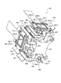
図6は、光変調素子保持体446の概略構成を示す分解斜視図である。
3つの光変調素子保持体446は、3つの光変調素子44Aをそれぞれ構成する3つの液晶パネル441をそれぞれ保持するとともに、内部に冷却流体が流入および流出し、該冷却流体により3つの液晶パネル441をそれぞれ冷却する。なお、各光変調素子保持体446は、同様の構成であり、以下では1つの光変調素子保持体446のみを説明する。
光変調素子保持体446は、図6に示すように、1対の枠状部材4461,4462と
、2つの弾性部材4463と、透光性基板4464と、透光性基板固定部材4465とを
備える。
枠状部材4461は、アルミニウム製の部材から構成され、略中央部分に液晶パネル4
41の画像形成領域に対応した矩形状の開口部4461Aを有する平面視略矩形状の枠体
であり、枠状部材4462に対して光束入射側に配置され、液晶パネル441を弾性部材
4463を介して光束入射側から枠状部材4462に対して押圧固定する。
FIG. 6 is an exploded perspective view showing a schematic configuration of the light modulation
The three light modulation
As shown in FIG. 6, the light
The frame-
41 is a substantially rectangular frame in plan view having a
この枠状部材4461において、光束射出側端面には、図6に示すように、液晶パネル
441の光束射出側端面を支持するための支持面4461Bが形成されている。
また、枠状部材4461において、上方側端部角隅部分および下方側端部角隅部分には
、図6に示すように、支持部材447の後述するピン状部材を挿通可能とする4つの孔4
461Cが形成されている。
さらに、枠状部材4461において、左右側端面には、図6に示すように、該左右側端
面に略直交して突出するとともに光束入射側に屈曲して延出するフィン4461Dがそれ
ぞれ形成されている。
これらフィン4461Dは、冷却流体から枠状部材4462に伝達された熱を外気との
熱交換により放熱するものである。
また、これらフィン4461Dの基端部分において、上下方向端部位置には、図6に示
すように、枠状部材4462と接続するための接続部4461Eが形成されている。
In the frame-shaped
Further, in the frame-shaped
461C is formed.
Further, in the frame-
These
Further, in the base end portion of these
図7は、枠状部材4462を光束射出側から見た斜視図である。
枠状部材4462は、略中央部分に液晶パネル441の画像形成領域に対応した矩形状
の開口4462Aを有する平面視略矩形状のアルミニウム製の枠体であり、上述した枠状
部材4461との間に、弾性部材4463を介して液晶パネル441を挟持するとともに
、枠状部材4461と対向する面と反対の面側にて弾性部材4463を介して透光性基板
4464を支持するものである。
この枠状部材4462において、光束射出側端面には、図7に示すように、弾性部材4
463の形状に対応して矩形枠状の凹部4462Bが形成され、この凹部4462Bにて
弾性部材4463を介して透光性基板4464を支持する。そして、枠状部材4462が
透光性基板4464を支持することで、弾性部材4463、および透光性基板4464の
光束入射側端面にて、開口4462Aにおける光束射出側が閉塞される。また、この凹部
4462Bの外周面には、複数の係止突起4462Cが形成され、これら係止突起446
2Cに弾性部材4463の外側面が当接し、弾性部材4463が位置決めされて凹部44
62Bに設置される。
FIG. 7 is a perspective view of the frame-
The frame-shaped
In the frame-
A rectangular frame-shaped
The outer surface of the
62B.
また、この枠状部材4462において、光束入射側端面にも、図示は省略するが、光束
射出側端面に形成された凹部4462Bと同様の凹部が形成され、前記凹部にて弾性部材
4463を介して液晶パネル441の光束射出側端面を支持する。そして、枠状部材44
62が液晶パネル441の光束射出側端面を支持することで、弾性部材4463および液
晶パネルの光束射出側端面にて、開口4462Aの光束入射側が閉塞される。また、光束
入射側端面にも、図示は省略するが、光束射出側端面に形成された係止突起4462Cと
同様の係止突起が形成されているものとする。
以上のように、液晶パネル441および透光性基板4464により開口4462Aの光
束入射側および光束射出側が閉塞されると、枠状部材4462内部に冷却流体を封入可能
とする冷却室R1(図8参照)が形成される。
Further, in this frame-
62 supports the light emission side end face of the
As described above, when the light incident side and the light emitting side of the
さらに、この枠状部材4462において、その下方側端部略中央部分には、図7に示す
ように、流体分岐部445の冷却流体流出部4452から流出した冷却流体を内部に流入
させる流入口4462Dが形成されている。この流入口4462Dは、流体循環部材44
8の管径寸法よりも小さい管径寸法を有する略筒状部材から構成され、枠状部材4462
の外側に突出するように形成されている。そして、流入口4462Dの突出した端部には
、流体分岐部445の冷却流体流出部4452に接続した流体循環部材448の他端が接
続され、該流体循環部材448を介して流体分岐部445から流出した冷却流体が枠状部
材4462の冷却室R1(図8参照)に流入する。
Further, in this frame-
The frame-shaped
It is formed so as to protrude outside. The other end of the
さらにまた、この枠状部材4462において、その上方側端部略中央部分には、図7に
示すように、枠状部材4462の冷却室R1(図8参照)内の冷却流体を外部に流出させ
る流出口4462Eが形成されている。すなわち、流出口4462Eは、流入口4462
Dの対向位置に形成されている。この流出口4462Eは、流入口4462Dと同様に、
流体循環部材448の管径寸法よりも小さい管径寸法を有する略筒状部材から構成され、
枠状部材4462の外側に突出するように形成されている。そして、流出口4462Eの
突出した端部には、流体分岐部445の冷却流体流入部4451に接続した流体循環部材
448の他端が接続され、冷却室R1(図8参照)内の冷却流体が該流体循環部材448
を介して流体分岐部445に流入される。
Furthermore, in the frame-
It is formed at a position opposite to D. This
Consists of a substantially cylindrical member having a pipe diameter smaller than the pipe diameter of the
It is formed so as to protrude outside the frame-
To flow into the
また、開口4462A周縁において、流入口4462Dおよび流出口4462Eと連通
する部位近傍は、図7に示すように、光束入射側に窪む凹部4462Fが形成され、該凹
部4462Fの外側面が前記部位に向けて幅狭となる形状となっている。
また、凹部4462Fの底面には、2つの整流部4462Gが立設されている。これら
整流部4462Gは、断面略直角三角形状であり、所定の間隔を空けて配置されるととも
に、直角三角形状の斜辺が互いに前記部位の離間方向に拡がるように配置されている。
Further, in the periphery of the
In addition, two rectifying
また、この枠状部材4462において、左側端部角隅部分および右側端部角隅部分には
、図7に示すように、枠状部材4461と接続するための接続部4462Hが形成されて
いる。
そして、枠状部材4461,4462の各接続部4461E,4462Hにねじ446
6(図6)を螺合することで、液晶パネル441が弾性部材4463を介して枠状部材4
461,4462間に挟持され、枠状部材4462の開口4462Aにおける光束入射側
が封止される。
さらに、この枠状部材4462において、左側端部略中央部分および右側端部略中央部
分には、図6または図7に示すように、透光性基板固定部材4465が係合するフック4
462Iが形成されている。
Further, in the frame-shaped
Then, screws 446 are connected to the
6 (FIG. 6) is screwed, so that the
The light beam incident side in the
Further, in the frame-
462I is formed.
弾性部材4463は、液晶パネル441と枠状部材4462、および、枠状部材446
2と透光性基板4464との間にそれぞれ介在配置され、枠状部材4462の冷却室R1
(図8参照)を封止し冷却流体の液漏れ等を防止するものである。この弾性部材4463
は、弾性を有するシリコンゴムで形成され、両面あるいは片面に表層の架橋密度を上げる
表面処理が施されている。例えば、弾性部材4463としては、サーコンGR−dシリー
ズ(冨士高分子工業の商標)を採用できる。ここで、端面に表面処理が施されていること
により、弾性部材4463を枠状部材4462の各凹部4462Bに設置する作業を容易
に実施できる。
なお、弾性部材4463は、水分透過量の少ないブチルゴムまたはフッ素ゴム等を使用
してもよい。
The
2 and the
(Refer to FIG. 8) is sealed to prevent leakage of the cooling fluid. This
Is formed of elastic silicon rubber and is subjected to a surface treatment for increasing the cross-linking density of the surface layer on both sides or one side. For example, as the
Note that the
透光性基板4464は、透光性を有する例えばガラス基板から構成される。
透光性基板固定部材4465は、透光性基板4464を、弾性部材4463を介して枠
状部材4462の凹部4462Bに押圧固定する。この透光性基板固定部材4465は、
略中央部分に開口部4465Aが形成された平面視略矩形枠体で構成され、開口部446
5A周縁部分にて、透光性基板4464を枠状部材4462に対して押圧する。また、透
光性基板固定部材4465には、左右側端縁にそれぞれフック係合部4465Bが形成さ
れ、フック係合部4465Bを枠状部材4462のフック4462Iに係合させることで
、枠状部材4462に対して透光性基板固定部材4465が透光性基板4464を押圧し
た状態で固定される。
The
The translucent
It is composed of a substantially rectangular frame in plan view in which an
The
支持部材447は、略中央部分に図示しない開口が形成された平面視略矩形枠状の板体
から構成され、光変調素子保持体446を支持し、該光変調素子保持体446とクロスダ
イクロイックプリズム444とを一体化するものである。この支持部材447としては、
例えば、アルミニウムから構成し、表面にブラックアルマイト処理を施したものを採用で
きる。なお、この支持部材447としては、光変調素子保持体446の構成材料であるア
ルミニウムと、クロスダイクロイックプリズム444の構成材料の略中間の熱膨張係数を
有する鉄系材料から構成してもよい。
この支持部材447において、光束入射側端面には、図2または図3に示すように、光
変調素子保持体446の4つの孔4461Cに対応した位置に、板体から突出するピン状
部材4471が形成されている。
また、この支持部材447において、上方側端部には、図2または図3に示すように、
光束射出側に向けて湾曲する湾曲部4472が形成されている。
そして、この支持部材447は、ピン状部材4471を光変調素子保持体446の4つ
の孔4461Cに挿通することで該光変調素子保持体446を支持し、板体の光束射出側
端面をクロスダイクロイックプリズム444に固定された射出側偏光板443の光束入射
側端面に接着固定することで、光変調素子保持体446がクロスダイクロイックプリズム
444と一体化される。
このように光変調素子保持体446をクロスダイクロイックプリズム444に対して固
定することで、支持部材447の湾曲部4472が射出側偏光板443の上方を覆うよう
に配置される(図8参照)。
以上説明したように、光学装置本体440において、冷却流体は、複数の流体循環部材
448を介して、流体分岐部445〜各光変調素子保持体446〜流体分岐部445とい
う流路を自然対流にて循環する。
The
For example, it is possible to employ a material made of aluminum and subjected to black alumite treatment on the surface. The
In the
Moreover, in this
A
The
By fixing the light modulation
As described above, in the optical device
次に、液晶パネル441の冷却構造を説明する。
図8は、液晶パネル441の冷却構造を説明するための断面図である。
光源装置411から射出された光束により、液晶パネル441に生じた熱は、光変調素
子保持体446の枠状部材4462における冷却室R1内の冷却流体に伝達される。
冷却室R1内の冷却流体に熱が伝達されることにより、他の冷却流体との間に温度差が
生じ、光学装置本体440における冷却流体の流路内に自然対流が生じる。
そして、冷却室R1内の冷却流体に伝達された熱は、冷却流体の流れにしたがって冷却
室R1〜流体分岐部445に移動する。流体分岐部445に温められた冷却流体が流入す
ると、冷却流体の熱は、流体分岐部445〜光学部品用筐体45の熱伝達経路を辿って放
熱される。冷却された冷却流体は、流体分岐部445〜冷却室R1へと再度、移動する。
また、冷却室R1内の冷却流体に伝達された熱は、枠状部材4461に伝達されるとと
もに、該枠状部材4461のフィン4461D(図6)に伝達される。
ここで、冷却ユニット3のシロッコファン31(図1)によりプロジェクタ1外部から
内部に導入された冷却空気は、光学部品用筐体45の底面に形成された孔451を介して
光学部品用筐体45内に導入される。光学部品用筐体45内に導入された冷却空気は、図
8に示すように、光変調素子保持体446の外面に沿って、下方から上方に向けて流通す
る。この際、冷却空気は、枠状部材4461のフィン4461D(図6)に伝達された熱
を冷却するとともに、液晶パネル441の光束入射側端面を冷却する。
Next, the cooling structure of the
FIG. 8 is a cross-sectional view for explaining a cooling structure of the
The heat generated in the
By transferring heat to the cooling fluid in the cooling chamber R <b> 1, a temperature difference occurs between the cooling fluid and the other cooling fluid, and natural convection occurs in the cooling fluid flow path in the optical device
Then, the heat transferred to the cooling fluid in the cooling chamber R1 moves to the cooling chamber R1 to the
In addition, the heat transmitted to the cooling fluid in the cooling chamber R1 is transmitted to the frame-
Here, the cooling air introduced from the outside of the projector 1 by the sirocco fan 31 (FIG. 1) of the
上述した第1実施形態においては、光変調素子保持体446を構成する枠状部材446
2には冷却室R1が形成され、冷却流体を内部に流入する流入口4462D、および冷却
流体を外部に流出する流出口4462Eを有しているので、複数の流体循環部材448に
て流入口4462Dおよび流出口4462Eを接続することで、冷却室R1内の冷却流体
を容易に対流させることができ、液晶パネル441により温められた冷却流体が冷却室R
1内に滞留することを回避できる。
また、流入口4462Dおよび流出口4462E近傍には、整流部4462Gが形成さ
れているので、流入口4462Dを介して冷却室R1内に流入した冷却流体を整流部44
62Gにて内部に拡げ、冷却室R1内の冷却流体を整流部4462Gにて集束させて流出
口4462Eを介して外部に流出させることができ、冷却室R1内全域に亘って冷却流体
を対流させることができる。このため、冷却室R1内に温められた冷却流体が局所的に滞
留することを回避できる。
したがって、液晶パネル441により冷却流体が温められて液晶パネル441と冷却流
体との温度差が小さくなることがなく、冷却流体により液晶パネル441を効率的に冷却
できる。
ここで、開口4462Aが液晶パネル441の画像形成領域に応じて設けられているの
で、冷却室R1に充填された冷却流体は、液晶パネル441の画像形成領域に接触する。
このことにより、液晶パネル441の画像形成領域内の温度分布が均一化され、局所的な
過熱を回避し、光変調素子44Aにて鮮明な光学像を形成できる。
In the first embodiment described above, the frame-shaped
2, the cooling chamber R1 is formed, and has an
It can avoid staying in 1.
Moreover, since the rectification | straightening
The inside of the cooling chamber R1 is expanded by 62G, and the cooling fluid in the cooling chamber R1 can be converged by the
Therefore, the cooling fluid is warmed by the
Here, since the
As a result, the temperature distribution in the image forming area of the
また、流入口4462Dおよび流出口4462Eは、枠状部材4462における対向す
る位置にそれぞれ形成されているので、冷却室R1内における冷却流体の流通を円滑に実
施でき、冷却流体の対流速度を速めることができる。このため、液晶パネル441と冷却
室R1内の冷却流体との温度差を維持し、冷却流体により液晶パネル441をさらに効率
的に冷却できる。
ここで、流入口4462Dが枠状部材4462の下方側端部に形成され、流出口446
2Eが枠状部材4462における上方側端部に形成されているので、熱の移動方向と冷却
流体の対流方向とを同一方向にすることができ、温められた冷却流体を冷却室R1外部へ
と容易に流出させることができる。
In addition, since the
Here, the
Since 2E is formed at the upper end of the frame-shaped
さらに、1対の枠状部材4461,4462が熱伝導性を有するアルミニウムから構成
されているので、液晶パネル441に生じた熱、および冷却室R1内の冷却流体に生じる
熱を枠状部材4461,4462に伝達できる。また、枠状部材4461の左右端縁には
、フィン4461Dが形成されているので、枠状部材4461に伝達された熱をフィン4
461Dにて放熱できる。さらに、冷却ユニット3のシロッコファン31により光変調素
子保持体446の外面に冷却空気が送風されるので、フィン4461Dに伝達された熱を
効率的に冷却でき、液晶パネル441の冷却効率をさらに向上できる。
Further, since the pair of frame-shaped
461D can dissipate heat. Furthermore, since the cooling air is blown to the outer surface of the light modulation
そして、光学装置本体440は、光変調素子保持体446の他、複数の流体循環部材4
48および流体分岐部445を備えているので、冷却室R1内だけでなく、複数の流体循
環部材448および流体分岐部445にも冷却流体を封入することで、冷却流体の容量を
大きくすることができ、液晶パネル441と冷却流体との熱交換能力を向上させることが
できる。
また、流体分岐部445には、各光変調素子保持体446の冷却室R1から温度の異な
る冷却流体が一括して送入され、送入された各冷却流体は、該流体分岐部445内にて混
合されて温度が均一化される。そして、流体分岐部445から温度が均一化された冷却流
体が分岐されて各光変調素子保持体446の冷却室R1に流入する。このことにより、各
光変調素子保持体446の冷却室R1に流入する冷却流体の温度が偏ることなく、略同一
の温度である冷却流体にて各液晶パネル441を冷却できる。
さらに、1つの流体分岐部445のみで、各光変調素子保持体446の冷却室R1から
流出される温度の異なる冷却流体を一括して送入し、送入した冷却流体を各光変調素子保
持体446毎に分岐して送出するので、光学装置本体440の構造の簡素化を図れる。ま
た、この流体分岐部445がクロスダイクロイックプリズム444の下面に固定されるの
で、光学装置本体440をコンパクトにでき、光学装置本体440の小型化を図れる。
The optical device
48 and the
In addition, cooling fluids having different temperatures are collectively sent to the
Further, only one
ここで、光学装置本体440を金属製材料からなる光学部品用筐体45に収納した際、
アルミニウムからなる流体分岐部445が光学部品用筐体45に熱伝達可能に接続するの
で、循環する冷却流体〜流体分岐部445〜光学部品用筐体45への熱伝達経路を確保し
、冷却流体の冷却効率を向上させ、ひいては、冷却流体による液晶パネル441の冷却効
率の向上を図れる。
また、流体分岐部445において、冷却流体流入部4451および冷却流体流出部44
52は、一方の端部が内部に向けて突出しているので、流体分岐部445の内部に蓄積さ
れた冷却流体のみを外部へと流出させることができる。例えば、流体分岐部445内部が
冷却流体にて満たされていない場合でも、空気を混入させることなく、冷却流体のみを外
部へと流出させることができる。また、冷却流体流出部4452のみならず、冷却流体流
入部4451も内部に突出しているので、冷却流体の対流方向が変わった場合、すなわち
、冷却流体流入部4451にて内部の冷却流体を外部に流出させ、冷却流体流出部445
2にて冷却流体を内部に流入させる場合でも、冷却流体流入部4451にて内部に蓄積さ
れた冷却流体のみを外部へと流出させることができる。
また、シロッコファン31の送風を光学部品用筐体45の底面に沿って流せば、循環す
る流体の放熱面積を増加でき、さらに、冷却効率が高められる。
Here, when the optical device
Since the
In the
52 has one end projecting toward the inside, so that only the cooling fluid accumulated in the
Even when the cooling fluid is caused to flow into the interior at 2, only the cooling fluid accumulated inside at the cooling
Further, if the
ところで、3つの光変調素子保持体446をクロスダイクロイックプリズム444の各
光束入射側端面に対してそれぞれ取り付ける際には、3つの液晶パネル441の相互の位
置調整を実施する必要がある。例えば、光変調素子保持体446とクロスダイクロイック
プリズム444との間に複数のスペーサを介在させ、該スペーサの位置を移動させること
で各液晶パネル441の相互の位置調整を実施する構成が考えられる。しかしながら、こ
のような構成では、複数のスペーサを設置する組み立て工数が増加するとともに、修理等
により各光変調素子保持体446を取り外す場合でも複数のスペーサをそれぞれ取り外す
という面倒な作業が生じてしまう。
本実施形態では、光変調素子保持体446に形成された4つの孔4461Cに支持部材
447に突設されたピン状部材4471を挿通し、支持部材447と光変調素子保持体4
46を接着固定し、クロスダイクロイックプリズム444の光束入射側端面に固定された
射出側偏光板443の光束入射側端面に支持部材447の光束射出側端面を固定すること
で、光変調素子保持体446とクロスダイクロイックプリズム444とを一体化すること
ができる。すなわち、上述したスペーサが、支持部材447に形成されたピン状部材44
71に相当し、スペーサが支持部材447に一体的に形成されていることで、光変調素子
保持体446をクロスダイクロイックプリズム444に対して取り付ける作業および取り
外す作業を容易に実施できる。
By the way, when the three light modulation
In the present embodiment, the pin-shaped
46 is bonded and fixed, and the light beam emission side end surface of the
71, and the spacer is formed integrally with the
また、入射側偏光板442および射出側偏光板443は、反射型偏光素子から構成されるので、所定の偏光軸以外の偏光軸を有する光束を吸収する吸収型偏光素子で構成した場合と比較して、熱が生じにくく、入射側偏光板442および射出側偏光板443自体の温度の低減を図れる。したがって、従来のように偏光素子を光変調素子保持体に保持させ、冷却流体により偏光素子を冷却する必要がなく、入射側偏光板442および射出側偏光板443により光変調素子保持体446における冷却室R1内の冷却流体の温度を増加させることもなく、液晶パネル441を冷却流体により効率的に冷却できる。したがって、入射側偏光板442、液晶パネル441、および射出側偏光板443で構成される光変調素子44Aの温度上昇による熱劣化を抑制し、光変調素子44Aにて良好な光学像を形成できる。
また、射出側偏光板443は、所定の偏光軸以外の偏光軸を有する光束を、液晶パネル
441の画像形成領域を避け、上方に向けて射出するので、光学装置本体440内に迷光
が生じることがなく、良好な光学像を形成できる。
In addition, since the incident-side
Further, since the exit-side
ここで、射出側偏光板443は、2つの直角プリズム4431と、反射型偏光膜443
2とを備え、2つの直角プリズム4431のうち入射側プリズム4431Aは、反射型偏
光膜4432にて反射された光束を光束入射側端面4431A1にて全反射させ、上方に
向けて射出するので、簡単な構成で、光学装置本体440内に迷光が生じることを回避で
きる。
また、支持部材447における上方側端縁には、湾曲部4472が形成されているので
、射出側偏光板443にて上方側に射出される光束を遮蔽でき、射出される光束が他の部
材に照射されることを回避できる。特に、上方側に射出される光束が複数の流体循環部材
448に照射されることを回避でき、流体循環部材448を流通する冷却流体の温度を増
加させることを回避でき、液晶パネル441の冷却効率が低下することを回避できる。
Here, the exit-side
Of the two right-
In addition, since a
そして、複数の流体循環部材448、流体分岐部445、1対の枠状部材4461,4
462は、耐蝕性を有するアルミニウムで構成されていることにより、長期間、冷却流体
と接触した場合でも化学反応を生じることを防止することができる。すなわち、化学反応
による反応性物質による冷却流体の着色等を回避し、冷却室R1内を通過する光束の光学
特性を変更することを防止できる。
そしてまた、プロジェクタ1は、上述した光学装置本体440を備えることで、液晶パ
ネル441の熱劣化を防止でき、プロジェクタ1の高寿命化を図れる。
A plurality of
Since 462 is made of corrosion-resistant aluminum, it can prevent a chemical reaction from occurring even when it is in contact with the cooling fluid for a long time. That is, it is possible to avoid coloring of the cooling fluid by a reactive substance due to a chemical reaction and to prevent the optical characteristics of the light beam passing through the cooling chamber R1 from being changed.
In addition, the projector 1 includes the optical device
[第2実施形態]
次に、本発明の第2実施形態を図面に基づいて説明する。
以下の説明では、前記第1実施形態と同様の構造および同一部材には同一符号を付して
、その詳細な説明は省略または簡略化する。
前記第1実施形態では、光学装置本体440は、冷却流体を蓄積する冷却流体蓄積部と
して流体分岐部445のみを有している。
これに対して第2実施形態では、光学装置本体540は、冷却流体を蓄積する冷却流体
蓄積部として流体分岐部545および中継タンク549を備える。その他の構成は、前記
第1実施形態と同様である。
[Second Embodiment]
Next, 2nd Embodiment of this invention is described based on drawing.
In the following description, the same structure and the same members as those in the first embodiment are denoted by the same reference numerals, and detailed description thereof is omitted or simplified.
In the first embodiment, the optical device
On the other hand, in the second embodiment, the optical device
具体的に、図9は、第2実施形態における光学装置本体540を上方側から見た斜視図
である。
図10は、光学装置本体540を下方側から見た斜視図である。
光学装置本体540は、図9または図10に示すように、前記第1実施形態で説明した
3つの液晶パネル441、射出側偏光板443、クロスダイクロイックプリズム444(
図9)、光変調素子保持体446、支持部材447、および複数の流体循環部材448の
他、上流側冷却流体蓄積部としての流体分岐部545と、下流側冷却流体蓄積部としての
中継タンク549(図9)とを備え、これら各部材441,443,444,446〜4
48,545,549が一体化されている。
なお、光学装置本体540において、冷却流体の対流方向が変わった場合には、流体分
岐部545が本発明に係る下流側冷却流体蓄積部に相当し、中継タンク549が本発明に
係る上流側冷却流体蓄積部に相当する。
Specifically, FIG. 9 is a perspective view of the optical device
FIG. 10 is a perspective view of the
As shown in FIG. 9 or FIG. 10, the optical device
9), a light modulation
48, 545, and 549 are integrated.
In the optical device
流体分岐部545は、前記第1実施形態で説明した流体分岐部445と略同様の構成を
有し、異なる点は、冷却流体流入部4451の形成位置および数、冷却流体流出部445
2の形成位置が異なるのみである。すなわち、流体分岐部545は、図9または図10に
示すように、前記第1実施形態の流体分岐部445の腕部4453(孔4453Aを含む
)を有する。また、図示は省略するが、流体分岐部545の上面には、前記第1実施形態
で説明した流体分岐部445の膨出部4454と同様の膨出部が形成されているものとす
る。
第2実施形態における流体分岐部545の冷却流体流入部5451(図9)は、クロス
ダイクロイックプリズム444の光束射出側端面に対応する側面に1つのみ形成されてい
る。そして、この冷却流体流入部5451は、流体循環部材448の一端と接続し、流体
循環部材448を介して、中継タンク549から流出した冷却流体を内部に流入させる。
また、第2実施形態における流体分岐部545の冷却流体流出部5452(図10)は
、クロスダイクロイックプリズム444の3つの光束入射側端面に対応する各側面の略中
央部分に形成されている。
The
Only the formation positions of the two are different. That is, as shown in FIG. 9 or FIG. 10, the
In the second embodiment, only one cooling fluid inflow portion 5451 (FIG. 9) of the
In addition, the cooling fluid outflow portion 5452 (FIG. 10) of the
図11は、中継タンク549の構造を示す図である。具体的に、図11(A)は、中継
タンク549を上方から見た平面図である。また、図11(B)は、図11(B)におけ
るB-B線の断面図である。
中継タンク549は、略円柱状のアルミニウム製の中空部材で構成され、クロスダイク
ロイックプリズム444の3つの光束入射側端面に交差する端面である上面に固定される
。そして、この中継タンク549は、各光変調素子保持体446から送出された冷却流体
を一括して送入し、送入した冷却流体を外部に送出する。
この中継タンク549において、その上面には、図11に示すように、各光変調素子保
持体446の各枠状部材4462から流出した冷却流体を内部に流入させる3つの冷却流
体流入部5491が形成されている。これら冷却流体流入部5491は、流体循環部材4
48の管径寸法よりも小さい管径寸法を有する略筒状部材から構成され、中継タンク54
9内外に突出するように配置されている。そして、各冷却流体流入部5491の外側に突
出した端部には、3つの光変調素子保持体446の流出口4462Eに接続された各流体
循環部材448の他端がそれぞれ接続され、該流体循環部材448を介して各光変調素子
保持体446から送出された冷却流体が一括して中継タンク549内部に流入する。
FIG. 11 is a diagram illustrating the structure of the
The
In the
The relay tank 54 is formed of a substantially cylindrical member having a pipe diameter smaller than 48 pipe diameters.
9 is arranged so as to protrude in and out. The other end of each
また、この中継タンク549において、外側面の下方側には、図11(A)に示すよう
に、送入した冷却流体を外部に流出させる冷却流体流出部5492が形成されている。こ
の冷却流体流出部5492は、冷却流体流入部5491と同様に、流体循環部材448の
管径寸法よりも小さい管径寸法を有する略筒状部材から構成され、中継タンク549内外
に突出するように配置されている。そして、冷却流体流出部5492の外側に突出した端
部には、流体分岐部545の冷却流体流入部5451に接続された流体循環部材448の
他端が接続され、該流体循環部材448を介して中継タンク549内部の冷却流体が流体
分岐部545内部に流入する。
以上説明したように、光学装置本体540において、冷却流体は、複数の流体循環部材
448を介して、流体分岐部545〜各光変調素子保持体446〜中継タンク549〜流
体分岐部545という流路を自然対流にて循環する。
In addition, in the
As described above, in the optical device
次に、液晶パネル441の冷却構造を説明する。
図12は、液晶パネル441の冷却構造を説明するための断面図である。
なお、第2実施形態における液晶パネル441の冷却構造は、前記第1実施形態で説明
した冷却構造と略同様であり、以下では、適宜、簡略化して説明する。
光源装置411から射出された光束により、液晶パネル441に生じた熱は、光変調素
子保持体446の枠状部材4462における冷却室R1内の冷却流体に伝達される。
冷却室R1内の冷却流体に熱が伝達されることにより、前記第1実施形態と同様に、光
学装置本体540における冷却流体の流路内に自然対流が生じる。
そして、各冷却室R1内の冷却流体に伝達された熱は、冷却流体の流れにしたがって各
冷却室R1〜中継タンク549〜流体分岐部545に移動する。流体分岐部545に温め
られた冷却流体が流入すると、冷却流体の熱は、前記第1実施形態と同様に、流体分岐部
545〜光学部品用筐体45の熱伝達経路を辿って放熱される。冷却された冷却流体は、
流体分岐部545〜冷却室R1へと再度、移動する。
また、冷却室R1内の冷却流体に伝達された熱は、前記第1実施形態と同様に、枠状部
材4461〜フィン4461D(図6)の熱伝達経路を辿って放熱され、さらに、冷却ユ
ニット3のシロッコファン31(図1)による冷却空気の強制冷却により液晶パネル44
1の光束入射側端面およびフィン4461D(図6)が冷却される。
Next, the cooling structure of the
FIG. 12 is a cross-sectional view for explaining a cooling structure of the
Note that the cooling structure of the
The heat generated in the
As heat is transferred to the cooling fluid in the cooling chamber R1, natural convection is generated in the flow path of the cooling fluid in the optical device
The heat transferred to the cooling fluid in each cooling chamber R1 moves to each cooling chamber R1,
It moves again from the
Further, the heat transferred to the cooling fluid in the cooling chamber R1 is dissipated through the heat transfer path of the frame-
The light beam incident side end face of 1 and the
上述した第2実施形態においては、前記第1実施形態と比較して、中継タンク549に
は、各光変調素子保持体446の冷却室R1から温度の異なる冷却流体が一括して送入さ
れ、送入された各冷却流体は、該中継タンク549内にて混合されて温度が均一化される
。そして、温度が均一化された冷却流体は、中継タンク549から流体分岐部545に流
入し、さらに、流体分岐部545にて分岐されて各光変調素子保持体446に流入する。
このことにより、中継タンク549および流体分岐部545の双方にて冷却流体の温度の
均一化を良好に実施でき、各光変調素子保持体446の冷却室R1に流入する冷却流体の
温度が偏ることなく、略同一の温度である冷却流体にて各液晶パネル441を冷却できる
。
また、光学装置本体540が中継タンク549を備えているので、該中継タンク549
にも冷却流体を封入することができ、冷却流体の容量をさらに大きくすることができ、液
晶パネル441と冷却流体との熱交換能力をさらに向上させることができる。
さらに、中継タンク549がクロスダイクロイックプリズム444の上面に固定される
ので、光学装置本体540をコンパクトにでき、光学装置本体540の小型化を図れる。
In the second embodiment described above, compared to the first embodiment, the
As a result, the temperature of the cooling fluid can be satisfactorily equalized in both the
Further, since the optical device
In addition, the cooling fluid can be enclosed, the capacity of the cooling fluid can be further increased, and the heat exchange capability between the
Further, since the
[第3実施形態]
次に、本発明の第3実施形態を図面に基づいて説明する。
以下の説明では、前記第1実施形態と同様の構造および同一部材には同一符号を付して
、その詳細な説明は省略または簡略化する。
前記第1実施形態では、光学装置44において、流体分岐部445にて分岐され3つの
光変調素子保持体446に流入する冷却流体の流量は、略同一に設定されている。
これに対して第4実施形態では、光学装置44において、各光変調素子保持体446に
流入する冷却流体の流量を変更可能とする流量変更部449を備える。その他の構成は、
前記第1実施形態と同様である。
[Third embodiment]
Next, 3rd Embodiment of this invention is described based on drawing.
In the following description, the same structure and the same members as those in the first embodiment are denoted by the same reference numerals, and detailed description thereof is omitted or simplified.
In the first embodiment, in the optical device 44, the flow rates of the cooling fluid branched by the
On the other hand, in the fourth embodiment, the optical device 44 includes a flow
The same as in the first embodiment.
具体的に、図13は、第3実施形態における流量変更部449の構造および設置位置を
示す図である。ここで、図13は、流体分岐部445を上方から見た平面図である。
流量変更部449は、図13に示すように、流体分岐部445の冷却流体流出部445
2にそれぞれ設けられ、各冷却流体流出部4452から各光変調素子保持体446に送入
される冷却流体の流量を変更可能に構成されている。この流量変更部449は、図13に
示すように、流量変更部本体449Aと、流量調整部449Bとを備える。
流量変更部本体449Aは、冷却流体を流通可能とする流路が形成されているとともに
、流量調整部449Bを回動可能に軸支する。
流量調整部449Bは、具体的な図示は省略するが、流量変更部本体449A内に配置
される調整弁と、流量変更部本体449Aの外側に突出する調整ねじとを備える。
このうち、前記調整弁は、回動位置に応じて流量変更部本体449A内の流路を狭めた
り、拡げたりして流路を通過する冷却流体の流量を変更可能とする。そして、前記調整弁
は、前記調整ねじの動きに連動し、前記調整ねじを手動にて回動させることにより、流量
変更部本体449Aの流路を通過する冷却流体の流量を変更可能とする。
Specifically, FIG. 13 is a diagram illustrating the structure and installation position of the flow
As shown in FIG. 13, the flow
2 is configured so that the flow rate of the cooling fluid sent from each cooling
The flow rate changing unit
Although not specifically shown, the flow
Among these, the said adjustment valve makes it possible to change the flow volume of the cooling fluid which passes a flow path by narrowing or expanding the flow path in the flow volume changing part
上述した第3実施形態においては、前記第1実施形態と比較して、流量変更部449の
流量調整部449Bを操作することにより、3つの液晶パネル441のうち、発熱量の大
きい液晶パネル441に対して冷却流体の流量を大きくし、発熱量の小さい液晶パネル4
41に対して冷却流体の流量を小さくすることで、各液晶パネル441の温度の均一化を
簡単な構成で容易にかつ、高精度に実施できる。したがって、各光変調素子44Aにて形
成される光学像の色合いを良好に維持することができる。
In the above-described third embodiment, by operating the flow
By reducing the flow rate of the cooling fluid with respect to 41, the temperature of each
[第4実施形態]
次に、本発明の第4実施形態を図面に基づいて説明する。
以下の説明では、前記第1実施形態と同様の構造および同一部材には同一符号を付して
、その詳細な説明は省略または簡略化する。
前記第1実施形態では、光学装置44において、流体分岐部445にて分岐され3つの
光変調素子保持体446に流入する冷却流体の流量は、略同一に設定されている。
これに対して第4実施形態では、流体分岐部745の各冷却流体流入部7451および
冷却流体流出部7452と、流体分岐部745および各光変調素子保持体446とを接続
する流体循環部材748の管径を異なるものとすることで、各光変調素子保持体446に
流入する冷却流体の流量を変更する。
[Fourth embodiment]
Next, 4th Embodiment of this invention is described based on drawing.
In the following description, the same structure and the same members as those in the first embodiment are denoted by the same reference numerals, and detailed description thereof is omitted or simplified.
In the first embodiment, in the optical device 44, the flow rates of the cooling fluid branched by the
On the other hand, in the fourth embodiment, the
具体的に、図14は、第4実施形態における流体分岐部745および該流体分岐部74
5と接続する流体循環部材748を示す図である。具体的に、図14は、流体分岐部74
5を下方から見た平面図である。
流体分岐部745は、前記第1実施形態で説明した流体分岐部445と略同様の構成で
あり、3つの冷却流体流入部7451および3つの冷却流体流出部7452の管径が異な
るように形成されている点が異なるのみである。
本実施形態では、G色光用の液晶パネル441を保持する光変調素子保持体446と冷
却流体を流通可能に接続する冷却流体流入部7451Gおよび冷却流体流出部7452G
の管径を最も大きい管径に設定し、B色光用の液晶パネル441を保持する光変調素子保
持体446と冷却流体を流通可能に接続する冷却流体流入部7451Bおよび冷却流体流
出部7452B、R色光用の液晶パネル441を保持する光変調素子保持体446と冷却
流体を流通可能に接続する冷却流体流入部7451Rおよび冷却流体流出部7452Rの
管径を順に、小さく設定している。
また、流体循環部材748も上述した各冷却流体流入部7451R,7451G,74
51Bおよび冷却流体流出部7452R,7452G,7452Bの管径に対応させて、
各流体循環部材748R,748G,748Bで管径を異なるものに設定している。
Specifically, FIG. 14 shows the
FIG. Specifically, FIG. 14 shows the fluid branch 74.
It is the top view which looked at 5 from the lower part.
The
In the present embodiment, the light modulation
The cooling
Further, the
Corresponding to the pipe diameters of 51B and cooling
The
上述した第4実施形態では、前記第1実施形態と比較して、各液晶パネル441の発熱
量に応じて、各冷却流体流入部7451R,7451G,7451B、各冷却流体流出部
7452R,7452G,7452B、およびこれらの管径に対応させて流体循環部材7
48R,748G,748Bの管径を異なるものに設定することで、各液晶パネル441
の温度の均一化を簡単な構成で容易に実施可能となる。したがって、各光変調素子44A
にて形成される光学像の色合いを良好に維持することができる。
In the above-described fourth embodiment, each cooling
By setting the pipe diameters of 48R, 748G, and 748B to different ones, each
The temperature can be made uniform with a simple configuration. Therefore, each
The hue of the optical image formed by the method can be maintained well.
以上、本発明について好適な実施形態を挙げて説明したが、本発明は、これらの実施形
態に限定されるものではなく、本発明の要旨を逸脱しない範囲において種々の改良並びに
設計の変更が可能である。
前記各実施形態では、光学装置本体440,540において、冷却流体を自然対流にて
対流させる構成を説明したが、光学装置本体440,540における冷却流体の流路中に
ポンプ等の流体圧送部を設け、強制的に冷却流体を循環させる構成としてもよい。
Although the present invention has been described with reference to preferred embodiments, the present invention is not limited to these embodiments, and various improvements and design changes can be made without departing from the scope of the present invention. It is.
In each of the embodiments described above, the configuration in which the cooling fluid is convected by natural convection in the optical device
前記各実施形態では、光変調素子保持体446は、透光性基板4464を1つ有する構
成であったが、これに限らず、透光性基板4464を2つ有する構成を採用してもよい。
すなわち、枠状部材4462の光束射出側に透光性基板4464を配置するとともに、枠
状部材4461の光束入射側にも透光性基板4464を配置する。そして、1対の枠状部
材4461,4462の各開口4461A,4462Aにおける対向する面側、および対
向する面と反対の面を、液晶パネル441および2つの透光性基板4464にてそれぞれ
閉塞することで、1対の枠状部材4461,4462双方の内部にそれぞれ冷却室が形成
される。このような構成では、液晶パネル441における光束入射側および光束射出側に
それぞれ冷却室が形成されることとなり、液晶パネル441の冷却効率をさらに向上させ
ることができる。
また、上述した構成において、入射側偏光板442および/または射出側偏光板443
を吸収型偏光素子として構成する。そして、透光性基板4464の代わりに吸収型偏光素
子である入射側偏光板および/または射出側偏光板を配置する構成を採用してもよい。
In each of the embodiments described above, the light modulation
That is, the
In the above-described configuration, the incident-side
Is configured as an absorptive polarizing element. In addition, a configuration in which an incident side polarizing plate and / or an emission side polarizing plate, which are absorption polarizing elements, may be employed instead of the
前記各実施形態において、光学装置本体440,540は、冷却流体蓄積部として流体
分岐部445,545、中継タンク549を備えていたが、これに限らず、これら冷却流
体蓄積部を省略した構成としてもよい。すなわち、光変調素子保持体446の流入口44
62Dおよび流出口4462Eを流体循環部材448にて直接、接続する構成としてもよ
い。このような構成でも、本発明の目的を十分に達成できる。
前記各実施形態において、枠状部材4462に形成される整流部4462Gは、流入口
4462Dの近傍および流出口4462Eの近傍にそれぞれ形成されていたが、これに限
らず、少なくとも流入口4462Dの近傍に形成されていればよい。また、整流部446
2Gの形状は、前記各実施形態で説明した形状に限らず、冷却室R1内に流入した冷却流
体を内部に広げるような形状であれば、その他の形状であっても構わない。
In each of the above embodiments, the optical device
62D and
In each of the above embodiments, the rectifying
The shape of 2G is not limited to the shape described in the above embodiments, and may be any other shape as long as the cooling fluid flowing into the cooling chamber R1 is expanded inside.
前記各実施形態では、光変調素子保持体446において、フィン4461Dは、枠状部
材4461の左右端縁に形成されていたが、これに限らず、枠状部材4462の左右端縁
に形成した構成を採用してもよく、枠状部材4461,4462の双方の左右端縁に形成
した構成を採用してもよい。
前記各実施形態において、光変調素子保持体446の孔4461Cは、4つに限らず、
少なくとも2つ形成されていればよい。また、支持部材447のピン状部材4471も4
つに限らず、光変調素子保持体446の孔4461Cの数に対応して形成すればよい。
In each of the embodiments described above, in the light modulation
In each of the embodiments, the number of
It is sufficient that at least two are formed. Further, the pin-
The number of
前記各実施形態において、射出側偏光板443は、2つの直角プリズム4431と、反
射型偏光膜4432とを備える構成であったが、これに限らず、ガラス等の透光性基板と
、該透光性基板上に形成され、金属等の導電性材料から構成され、透光性基板から突出し
かつ、透光性基板の面内方向に延出する複数の突条部が縞状に並列は位置された無機材料
からなる反射型偏光素子として構成してもよい。この際、所定の偏光軸以外の偏光軸を有
する光束を液晶パネル441の画像形成領域を避ける方向に反射させるには、上述した無
機材料からなる反射型偏光素子を液晶パネル441の光束入射側端面または光束射出側端
面に対して傾斜させて配置させればよい。
In each of the embodiments described above, the exit-side
前記各実施形態において、流体分岐部445,545,745、中継タンク549は、
冷却流体流入部4451,5451,5491,7451および冷却流体流出部4452
,5452,5492,7452を有し、冷却流体流入部4451,5451,5491
,7451および冷却流体流出部4452,5452,5492,7452の一方の端部
が内部に向けて突出している構成を説明したが、これに限らない。例えば、流体分岐部4
45,545,745、中継タンク549に直接、流体循環部材448,748を連通接
続し、流体循環部材448,748の端部を流体分岐部445,545,745、中継タ
ンク549内部に突出させる構成としてもよい。
In each of the above embodiments, the
Cooling
, 5452, 5492, 7452 and cooling
7451 and one end of the cooling
45, 545, 745, and
前記各実施形態において、冷却流体と接触する部材である、流体循環部材448,74
8、流体分岐部445,545,745、中継タンク549、および枠状部材4461,
4462は、アルミニウム製の部材から構成したが、これに限らない。耐蝕性を有する材
料であれば、アルミニウムに限らず、他の材料にて構成してもよく、例えば、無酸素銅や
ジュラルミンにて構成してもよい。
また、流体循環部材448,748は、光変調素子保持体446への変形反力が小さく
画素ずれを抑制する硬度の低いブチルゴムまたはフッ素ゴム等を使用してもよい。
In each of the above embodiments, the
8,
Although 4462 was comprised from the member made from aluminum, it is not restricted to this. As long as the material has corrosion resistance, the material is not limited to aluminum, and may be composed of other materials, for example, oxygen-free copper or duralumin.
Further, the
前記第2実施形態では、光学装置本体540を光学部品用筐体45に対して収納した際
、流体分岐部545を光学部品用筐体45に対して熱伝達可能に接続する構成を説明した
が、中継タンク549を光学部品用筐体45に対して熱伝達可能に接続してもよく、流体
分岐部545および中継タンク549の双方を光学部品用筐体45に対して熱伝達可能に
接続してもよい。
In the second embodiment, the configuration in which the
前記各実施形態では、シロッコファン31の送風によって、光変調素子保持体446の
外面ならびに光学部品用筐体45の底面を冷却していたが、これに限らず、シロッコファ
ン31を省略した構成を採用してもよい。このような構成では、低騒音化に寄与できる。
In each of the embodiments described above, the outer surface of the light modulation
前記第3実施形態における流量変更部449は、前記第1実施形態に採用する構成に限
らず、前記第2実施形態に採用してもよい。また、流量変更部449は、各液晶パネル4
41に対応して3つで構成されていたが、これに限らず、1つ、または、2つで構成して
もよい。さらに、流量変更部449は、流体分岐部445の冷却流体流出部4452に設
けた構成を説明したが、これに限らず、冷却流体流出部4452と接続する流体循環部材
448に設けてもよい。さらにまた、流量変更部449の構成は、前記第3実施形態で説
明した構成に限らず、冷却流体の流路中に弁を設け、該弁の位置を変更することで流路を
狭めたり拡げたりする構成であれば、他の構成であっても構わない。
The flow
However, the present invention is not limited to this, and may be composed of one or two. Furthermore, although the structure provided in the cooling
前記第4実施形態における流体分岐部745および流体分岐部745と接続する流体循
環部材748は、前記第1実施形態に採用する構成に限らず、前記第2実施形態に採用し
てもよい。また、流体分岐部745の各冷却流体流入部7451、各冷却流体流出部74
52、およびこれらと接続する流体循環部材748の各管径をそれぞれ異なるように設定
していたが、これに限らず、各管径のうち、1つのみの管径を他の管径よりも小さく、あ
るいは大きくした構成を採用してもよい。
前記各実施形態では、光学ユニット4が平面視略L字形状を有した構成を説明したが、
これに限らず、例えば、平面視略U字形状を有した構成を採用してもよい。
前記各実施形態では、3つの光変調素子44Aを用いたプロジェクタ1の例のみを挙げ
たが、本発明は、1つの光変調素子のみを用いたプロジェクタ、2つの光変調素子のみを
用いたプロジェクタ、あるいは、4つ以上の光変調素子を用いたプロジェクタにも適用可
能である。
前記各実施形態では、光入射面と光射出面とが異なる透過型の液晶パネルを用いた光変調素子44Aを採用していたが、光入射面と光射出面とが同一となる反射型の液晶パネルを用いた光変調素子を採用してもよい。
前記各実施形態では、液晶パネル441を有する光変調素子44A用いていたが、マイクロミラーを用いたデバイスなど、液晶以外の光変調素子を用いてもよい。この場合は、光束入射側および光束射出側の偏光板は省略できる。
前記各実施形態では、スクリーンを観察する方向から投写を行なうフロントタイプのプ
ロジェクタの例のみを挙げたが、本発明は、スクリーンを観察する方向とは反対側から投
写を行なうリアタイプのプロジェクタにも適用可能である。
The
52, and the pipe diameters of the
In each of the embodiments described above, the configuration in which the
For example, a configuration having a substantially U shape in plan view may be employed.
In each of the above-described embodiments, only the example of the projector 1 using the three
In each of the above-described embodiments, the
In each of the above embodiments, the
In each of the above embodiments, only an example of a front type projector that performs projection from the direction of observing the screen has been described. However, the present invention also applies to a rear type projector that performs projection from the side opposite to the direction of observing the screen. Applicable.
本発明を実施するための最良の構成などは、以上の記載で開示されているが、本発明は
、これに限定されるものではない。すなわち、本発明は、主に特定の実施形態に関して特
に図示され、かつ、説明されているが、本発明の技術的思想および目的の範囲から逸脱す
ることなく、以上述べた実施形態に対し、形状、材質、数量、その他の詳細な構成におい
て、当業者が様々な変形を加えることができるものである。
したがって、上記に開示した形状、材質などを限定した記載は、本発明の理解を容易に
するために例示的に記載したものであり、本発明を限定するものではないから、それらの
形状、材質などの限定の一部若しくは全部の限定を外した部材の名称での記載は、本発明
に含まれるものである。
Although the best configuration for carrying out the present invention has been disclosed in the above description, the present invention is not limited to this. That is, the invention has been illustrated and described primarily with respect to particular embodiments, but may be configured for the above-described embodiments without departing from the scope and spirit of the invention. Various modifications can be made by those skilled in the art in terms of materials, quantity, and other detailed configurations.
Therefore, the description limited to the shape, material, etc. disclosed above is an example for easy understanding of the present invention, and does not limit the present invention. The description by the name of the member which remove | excluded the limitation of one part or all of such is included in this invention.
本発明の光変調素子保持体は、冷却流体により光変調素子を効率的に冷却できるため、
ホームシアターやプレゼンテーションで利用されるプロジェクタの光変調素子保持体とし
て有用である。
Since the light modulation element holding body of the present invention can efficiently cool the light modulation element by the cooling fluid,
It is useful as a light modulation element holder for projectors used in home theaters and presentations.
1・・・プロジェクタ、5・・・投射レンズ(投射光学装置)、45・・・光学部品用
筐体、411・・・光源装置、44・・・光学装置、441・・・液晶パネル(光変調素
子)、443・・・射出側偏光板(反射型偏光素子)、444・・・クロスダイクロイッ
クプリズム(色合成光学装置)、445・・・流体分岐部(冷却流体蓄積部)、446・
・・光変調素子保持体、447・・・支持部材、448・・・流体循環部材、449・・
・流量変更部、549・・・中継タンク(冷却流体蓄積部)、4431・・・プリズム、
4431A・・・入射側プリズム、4431A1・・・光束入射側端面、4432・・・
反射型偏光膜、4451,5451,5491,7451・・・冷却流体流入部、445
2,5452,5492,7452・・・冷却流体流出部、4461,4462・・・枠
状部材、4461A,4462A・・・開口、4461C・・・孔、4461D・・・フ
ィン、4462D・・・流入口、4462E・・・流出口、4462G・・・整流部、4
464・・・透光性基板、4471・・・ピン状部材、4472・・・湾曲部、R1・・
・冷却室。
DESCRIPTION OF SYMBOLS 1 ... Projector, 5 ... Projection lens (projection optical apparatus), 45 ... Housing for optical components, 411 ... Light source device, 44 ... Optical apparatus, 441 ... Liquid crystal panel (light) Modulating element), 443... Emission side polarizing plate (reflection type polarizing element), 444... Cross dichroic prism (color synthesis optical device), 445.
..Light modulation element holder, 447 ... support member, 448 ... fluid circulation member, 449
-Flow rate change unit, 549 ... Relay tank (cooling fluid storage unit), 4431 ... Prism,
4431A: Incident side prism, 4431A1: Light incident side end surface, 4432 ...
Reflective polarizing film, 4451, 5451, 5491, 7451 ... cooling fluid inflow portion, 445
2, 5452, 5492, 7452 ... Cooling fluid outlet, 4461, 4462 ... Frame member, 4461A, 4462A ... Opening, 4461C ... Hole, 4461D ... Fin, 4462D ... Flow Inlet, 4462E ... Outlet, 4462G ... Rectifier, 4
464... Translucent substrate, 4471... Pin-shaped member, 4472.
・ Cooling room.
Claims (15)
持し、内部に冷却流体が封入される冷却室が形成され、前記冷却室内の冷却流体により前
記光変調素子を冷却する光変調素子保持体であって、
前記光変調素子の画像形成領域に応じてそれぞれ開口が形成され、前記光変調素子を挟
持する1対の枠状部材と、
前記1対の枠状部材における対向する面と反対の面のうち少なくともいずれかの面側に
配置される透光性基板とを含んで構成され、
前記冷却室は、前記1対の枠状部材の前記開口における前記対向する面側、および前記
対向する面と反対の面のうち少なくともいずれかの面側が前記光変調素子および前記透光
性基板にてそれぞれ閉塞されることにより前記1対の枠状部材のうち少なくともいずれか
の枠状部材の内部に形成され、
前記冷却室が内部に形成される枠状部材は、前記冷却室に前記冷却流体を流入させる流
入口と、前記冷却室内部の前記冷却流体を外部に流出させる流出口とを有し、
前記流入口近傍には、前記冷却流体を前記冷却室内部に拡げるように流入させる整流部
が形成されていることを特徴とする光変調素子保持体。 A light modulation element that modulates the light beam emitted from the light source according to image information to form an optical image is held, and a cooling chamber in which a cooling fluid is enclosed is formed. A light modulation element holder for cooling the modulation element,
A pair of frame-shaped members each having an opening formed in accordance with an image forming region of the light modulation element and sandwiching the light modulation element;
A translucent substrate disposed on at least one of the opposite surfaces of the pair of frame-shaped members;
In the cooling chamber, at least one of the facing surface side and the surface opposite to the facing surface in the opening of the pair of frame-shaped members is on the light modulation element and the translucent substrate. Are formed inside at least one of the pair of frame-shaped members by being closed,
The frame-like member in which the cooling chamber is formed has an inlet that allows the cooling fluid to flow into the cooling chamber, and an outlet that flows the cooling fluid inside the cooling chamber to the outside.
In the vicinity of the inflow port, there is formed a rectifying unit that allows the cooling fluid to flow into the inside of the cooling chamber, so that the light modulation element holder is provided.
前記流入口および前記流出口は、前記枠状部材における対向する位置にそれぞれ形成さ
れていることを特徴とする光変調素子保持体。 The light modulation element holding body according to claim 1,
The inflow port and the outflow port are respectively formed at opposing positions in the frame-shaped member.
前記1対の枠状部材は、熱伝導性材料から構成され、
前記1対の枠状部材のうち少なくともいずれかの枠状部材には、その端縁に放熱用の冷
却フィンが形成されていることを特徴とする光変調素子保持体。 In the light modulation element holder according to claim 1 or 2,
The pair of frame-shaped members are made of a heat conductive material,
At least one of the pair of frame-shaped members has a heat-radiating cooling fin formed on an edge of the frame-shaped member.
んで構成される光学装置であって、
請求項1から請求項3のいずれかに記載の光変調素子保持体と、
前記光変調素子保持体の流入口および流出口と接続され、前記冷却流体を前記冷却室外
部に案内し、再度、前記冷却室内部に導く複数の流体循環部材と、
前記複数の流体循環部材における前記冷却流体の流路中に配置され、前記冷却流体を蓄
積する冷却流体蓄積部とを備えていることを特徴とする光学装置。 An optical device configured to include a light modulation element that modulates a light beam emitted from a light source according to image information to form an optical image,
The light modulation element holding body according to any one of claims 1 to 3,
A plurality of fluid circulation members connected to the inlet and the outlet of the light modulation element holding body, guiding the cooling fluid to the outside of the cooling chamber, and again guiding the cooling fluid to the inside of the cooling chamber;
An optical apparatus comprising: a cooling fluid storage unit that is disposed in a flow path of the cooling fluid in the plurality of fluid circulation members and stores the cooling fluid.
前記光変調素子は、複数で構成され、
前記光変調素子保持体は、前記複数の光変調素子に対応して複数で構成され、
前記複数の光変調素子保持体が取り付けられる複数の光束入射側端面を有し、前記複数
の光変調素子にて変調された各色光を合成して射出する色合成光学装置を備え、
前記冷却流体蓄積部は、前記色合成光学装置の前記複数の光束入射側端面と交差する端
面のうちいずれか一方の端面に取り付けられ、各光変調素子保持体から前記複数の流体循
環部材を介して前記冷却流体を一括して送入するとともに、内部の冷却流体を前記複数の
流体循環部材を介して前記複数の光変調素子保持体毎に分岐して送出することを特徴とす
る光学装置。 The optical device according to claim 4.
The light modulation element comprises a plurality of;
The light modulation element holding body is composed of a plurality corresponding to the plurality of light modulation elements,
A plurality of light beam incident side end faces to which the plurality of light modulation element holders are attached, and a color combining optical device that combines and emits each color light modulated by the plurality of light modulation elements,
The cooling fluid accumulating unit is attached to any one of the end surfaces intersecting with the plurality of light incident side end surfaces of the color synthesizing optical device, and from each light modulation element holding body via the plurality of fluid circulation members. The cooling fluid is sent in a batch, and the internal cooling fluid is branched and sent to each of the plurality of light modulation element holders via the plurality of fluid circulation members.
前記光変調素子は、複数で構成され、
前記光変調素子保持体は、前記複数の光変調素子に対応して複数で構成され、
前記複数の光変調素子保持体が取り付けられる複数の光束入射側端面を有し、前記複数
の光変調素子にて変調された各色光を合成して射出する色合成光学装置を備え、
前記冷却流体蓄積部は、前記光変調素子保持体に対して前記冷却流体の上流側に配置さ
れ、蓄積した冷却流体を前記複数の流体循環部材を介して前記複数の光変調素子保持体毎
に分岐して送出する上流側冷却流体蓄積部と、前記光変調素子保持体に対して前記冷却流
体の下流側に配置され、各光変調素子保持体から前記複数の流体循環部材を介して前記冷
却流体を一括して送入する下流側冷却流体蓄積部とで構成され、
前記上流側冷却流体蓄積部は、前記色合成光学装置の前記複数の光束入射側端面と交差
する端面のうちいずれか一方の端面に取り付けられ、
前記下流側冷却流体蓄積部は、前記色合成光学装置の前記複数の光束入射側端面と交差
する端面のうちいずれか他方の端面に取り付けられることを特徴とする光学装置。 The optical device according to claim 4.
The light modulation element comprises a plurality of;
The light modulation element holding body is composed of a plurality corresponding to the plurality of light modulation elements,
A plurality of light beam incident side end faces to which the plurality of light modulation element holders are attached, and a color combining optical device that combines and emits each color light modulated by the plurality of light modulation elements,
The cooling fluid accumulation unit is disposed upstream of the cooling fluid with respect to the light modulation element holder, and the accumulated cooling fluid is supplied to each of the plurality of light modulation element holders via the plurality of fluid circulation members. An upstream side cooling fluid accumulating unit that branches and sends out, and is arranged on the downstream side of the cooling fluid with respect to the light modulation element holder, and the cooling from each light modulation element holder through the plurality of fluid circulation members It consists of a downstream side cooling fluid accumulator that feeds fluids in a batch,
The upstream side cooling fluid accumulating unit is attached to any one of the end surfaces intersecting with the plurality of light beam incident side end surfaces of the color synthesizing optical device,
The downstream side cooling fluid accumulating unit is attached to any one of the end surfaces intersecting with the plurality of light beam incident side end surfaces of the color synthesizing optical device.
前記光変調素子保持体および前記色合成光学装置の間に介在配置され、前記色合成光学
装置の複数の光束入射側端面に対して前記複数の光変調素子保持体を取り付けるための複
数の支持部材を備え、
前記光変調素子保持体の少なくとも2箇所には孔が形成され、
前記支持部材は、前記光変調素子保持体の開口と対応する位置に開口が形成された矩形
板状体と、前記矩形板状体の光束入射側端面から突設され、前記光変調素子保持体の前記
孔に挿入されるピン状部材とを備えていることを特徴とする光学装置。 The optical device according to claim 5 or 6,
A plurality of support members that are interposed between the light modulation element holding body and the color combining optical device, and for attaching the plurality of light modulation element holding bodies to a plurality of light beam incident side end faces of the color combining optical device. With
Holes are formed in at least two places of the light modulation element holder,
The support member is provided with a rectangular plate-like body having an opening formed at a position corresponding to the opening of the light-modulating element holder, and a light beam incident side end surface of the rectangular plate-like body, and the light-modulating element holder An optical device comprising: a pin-like member inserted into the hole.
前記光変調素子保持体および前記色合成光学装置の間に介在配置され、前記複数の光変
調素子から射出される光束のうち、所定の偏光軸を有する光束をそれぞれ透過させ、他の
偏光軸を有する光束をそれぞれ反射する複数の反射型偏光素子を備え、
前記反射型偏光素子は、前記他の偏光軸を有する光束を前記光変調素子の画像形成領域
を避ける方向に反射することを特徴とする光学装置。 The optical device according to any one of claims 5 to 7,
Among the light beams emitted from the plurality of light modulation elements, each of which is interposed between the light modulation element holder and the color synthesizing optical device and transmits a light beam having a predetermined polarization axis. A plurality of reflective polarizing elements that respectively reflect the luminous flux having
The optical apparatus, wherein the reflective polarizing element reflects a light beam having the other polarization axis in a direction avoiding an image forming area of the light modulation element.
前記反射型偏光素子は、相互に接続される複数のプリズムと、前記複数のプリズム間に
介装され、前記光変調素子から射出される光束のうち、所定の偏光軸を有する光束を透過
させ、他の偏光軸を有する光束を反射する反射型偏光膜とで構成され、
前記複数のプリズムは、光束入射側に配置され、前記光変調素子から射出される光束に
対する透過面と、前記反射型偏光膜にて反射された光束に対する全反射面とを兼ねる光束
入射側端面を有する入射側プリズムを含んで構成され、
前記入射側プリズムは、前記反射型偏光膜にて反射された光束を前記全反射面にて反射
させ、前記光変調素子の画像形成領域を避ける方向に射出することを特徴とする光学装置
。 The optical device according to claim 8.
The reflective polarizing element is interposed between the plurality of prisms connected to each other, and transmits a light beam having a predetermined polarization axis among light beams emitted from the light modulation element, It is composed of a reflective polarizing film that reflects a light beam having another polarization axis,
The plurality of prisms are arranged on a light beam incident side, and have a light beam incident side end surface that serves as a transmission surface for the light beam emitted from the light modulation element and a total reflection surface for the light beam reflected by the reflective polarizing film. Including an incident side prism having,
The optical device, wherein the incident-side prism reflects the light beam reflected by the reflective polarizing film at the total reflection surface and emits the light in a direction avoiding an image forming area of the light modulation element.
前記光変調素子保持体および前記反射型偏光素子の間に介在配置され、前記色合成光学
装置の複数の光束入射側端面に対して前記複数の光変調素子保持体を取り付けるための複
数の支持部材を備え、
前記光変調素子保持体の少なくとも2箇所には孔が形成され、
前記支持部材は、前記光変調素子保持体の開口と対応する位置に開口が形成された矩形
板状体と、前記矩形板状体の光束入射側端面から突設され、前記光変調素子保持体の前記
孔に挿入されるピン状部材とを備え、
前記矩形板状体の端縁には、光束射出側に向けて湾曲し、前記反射型偏光素子にて反射
される光束を遮蔽する湾曲部が形成されていることを特徴とする光学装置。 The optical device according to claim 8 or 9,
A plurality of support members that are interposed between the light modulation element holder and the reflective polarizing element, and for attaching the plurality of light modulation element holders to a plurality of light beam incident side end faces of the color combining optical device. With
Holes are formed in at least two places of the light modulation element holder,
The support member is provided with a rectangular plate-like body having an opening formed at a position corresponding to the opening of the light-modulating element holder, and a light beam incident side end surface of the rectangular plate-like body, and the light-modulating element holder A pin-like member inserted into the hole,
An optical device, characterized in that a curved portion is formed on an edge of the rectangular plate-like body so as to bend toward the light beam exit side and shield the light beam reflected by the reflective polarizing element.
前記複数の光変調素子の発熱量に応じて、前記各光変調素子保持体に流通する前記冷却
流体の流量を変更可能とする流量変更部を備えていることを特徴とする光学装置。 The optical device according to any one of claims 5 to 10,
An optical apparatus comprising: a flow rate changing unit that can change a flow rate of the cooling fluid flowing through each of the light modulation element holding bodies according to a heat generation amount of the plurality of light modulation elements.
前記複数の流体循環部材は、管状部材から構成され、前記複数の光変調素子の発熱量に
応じて管径寸法が異なるように形成されていることを特徴とする光学装置。 The optical device according to any one of claims 5 to 10,
The optical device is characterized in that the plurality of fluid circulation members are formed of tubular members and have different tube diameters according to the amount of heat generated by the plurality of light modulation elements.
前記冷却流体蓄積部は、前記複数の流体循環部材と接続し前記冷却流体を内部に流入さ
せる冷却流体流入部、および前記冷却流体を外部に流出させる冷却流体流出部を有し、
前記冷却流体流入部および前記冷却流体流出部は、前記冷却流体を流通可能な管形状を
有し、一方の端部が前記冷却流体蓄積部の内部に向けて突出していることを特徴とする光
学装置。 The optical device according to any one of claims 4 to 12,
The cooling fluid accumulating unit has a cooling fluid inflow portion that is connected to the plurality of fluid circulation members and allows the cooling fluid to flow into the inside, and a cooling fluid outflow portion that causes the cooling fluid to flow out to the outside,
The cooling fluid inflow portion and the cooling fluid outflow portion have a tube shape through which the cooling fluid can flow, and one end protrudes toward the inside of the cooling fluid accumulation portion. apparatus.
て形成された光学像を拡大投射する投射光学装置とを備えていることを特徴とするプロジ
ェクタ。 A projector comprising: a light source device; the optical device according to any one of claims 4 to 13; and a projection optical device that enlarges and projects an optical image formed by the optical device.
前記光学装置を前記投射光学装置に対する所定位置に収納する熱伝導性材料からなる光
学部品用筐体を備え、
前記光学装置を構成する光変調素子は、複数で構成され、
前記光学装置を構成する光変調素子保持体は、前記複数の光変調素子に対応して複数で
構成され、
前記光学装置は、前記複数の光変調素子保持体が取り付けられる複数の光束入射側端面
を有し、前記複数の光変調素子にて変調された各色光を合成して射出する色合成光学装置
を備え、
前記光学装置を構成する冷却流体蓄積部は、熱伝導性材料から構成され、前記色合成光
学装置の前記複数の光束入射側端面と交差する端面のうち少なくともいずれか一方の端面
に取り付けられ、前記光学装置を前記光学部品用筐体に収納した際、前記光学部品用筐体
と熱伝達可能に接続することを特徴とするプロジェクタ。 The projector according to claim 14, wherein
An optical component housing made of a thermally conductive material that houses the optical device in a predetermined position with respect to the projection optical device;
The light modulation element constituting the optical device is composed of a plurality of
The light modulation element holding body constituting the optical device is constituted by a plurality corresponding to the plurality of light modulation elements,
The optical device has a plurality of light beam incident side end faces to which the plurality of light modulation element holders are attached, and a color combining optical device that combines and emits each color light modulated by the plurality of light modulation elements. Prepared,
The cooling fluid accumulating unit constituting the optical device is made of a heat conductive material, and is attached to at least one of the end surfaces intersecting with the plurality of light beam incident side end surfaces of the color synthesis optical device, When the optical device is accommodated in the optical component casing, the projector is connected to the optical component casing so as to be able to transfer heat.
Priority Applications (1)
| Application Number | Priority Date | Filing Date | Title |
|---|---|---|---|
| JP2004376800A JP2005208632A (en) | 2003-12-26 | 2004-12-27 | Light modulation element holder, optical device, and projector |
Applications Claiming Priority (2)
| Application Number | Priority Date | Filing Date | Title |
|---|---|---|---|
| JP2003433306 | 2003-12-26 | ||
| JP2004376800A JP2005208632A (en) | 2003-12-26 | 2004-12-27 | Light modulation element holder, optical device, and projector |
Publications (1)
| Publication Number | Publication Date |
|---|---|
| JP2005208632A true JP2005208632A (en) | 2005-08-04 |
Family
ID=34914271
Family Applications (1)
| Application Number | Title | Priority Date | Filing Date |
|---|---|---|---|
| JP2004376800A Withdrawn JP2005208632A (en) | 2003-12-26 | 2004-12-27 | Light modulation element holder, optical device, and projector |
Country Status (1)
| Country | Link |
|---|---|
| JP (1) | JP2005208632A (en) |
Cited By (2)
| Publication number | Priority date | Publication date | Assignee | Title |
|---|---|---|---|---|
| JP2009258646A (en) * | 2008-03-19 | 2009-11-05 | Seiko Epson Corp | Optical apparatus and projector |
| KR20180113611A (en) * | 2016-03-03 | 2018-10-16 | 제트카베 그룹 게엠베하 | Component housings in vehicle headlights |
-
2004
- 2004-12-27 JP JP2004376800A patent/JP2005208632A/en not_active Withdrawn
Cited By (3)
| Publication number | Priority date | Publication date | Assignee | Title |
|---|---|---|---|---|
| JP2009258646A (en) * | 2008-03-19 | 2009-11-05 | Seiko Epson Corp | Optical apparatus and projector |
| KR20180113611A (en) * | 2016-03-03 | 2018-10-16 | 제트카베 그룹 게엠베하 | Component housings in vehicle headlights |
| KR102112304B1 (en) | 2016-03-03 | 2020-05-19 | 제트카베 그룹 게엠베하 | Component housing of vehicle headlight |
Similar Documents
| Publication | Publication Date | Title |
|---|---|---|
| JP4227969B2 (en) | Projection display | |
| JP4192882B2 (en) | Optical device and projector | |
| US6966653B2 (en) | Cooling device and optical device and projector having the cooling device | |
| JP4419646B2 (en) | Optical apparatus and projector | |
| JP4096904B2 (en) | Light modulation element holder, optical device, and projector | |
| KR100691056B1 (en) | Optics and Rear Projector | |
| JP2004070116A (en) | Optical device, optical unit, and projector | |
| WO2005064397A1 (en) | Optical device and projector | |
| US7073912B2 (en) | Optical parts casing and projector | |
| JP2005121250A (en) | Cooling device and rear projector | |
| JP3966288B2 (en) | Light modulation element holder, optical device, and projector | |
| JP4096897B2 (en) | OPTICAL DEVICE, OPTICAL DEVICE MANUFACTURING METHOD, AND PROJECTOR | |
| JP4151584B2 (en) | Optical device and projector | |
| JP3992005B2 (en) | Optical device and projector | |
| JP4860663B2 (en) | Liquid crystal unit cooling method | |
| JP2005208632A (en) | Light modulation element holder, optical device, and projector | |
| JP2004021116A (en) | Optical element cooling device, optical device, and projector | |
| JP6885034B2 (en) | Optics and projectors | |
| JP2007041414A (en) | Electronics | |
| JP6805751B2 (en) | Optics and projectors | |
| JP2005215198A (en) | Light modulation element holder, optical device, and projector | |
| JP2006030400A (en) | projector | |
| JP2005114994A (en) | Optical device and rear projector | |
| JP2005338347A (en) | Optical device and projector | |
| JP2006126456A (en) | Light modulation element holder, optical device, and projector |
Legal Events
| Date | Code | Title | Description |
|---|---|---|---|
| RD02 | Notification of acceptance of power of attorney |
Free format text: JAPANESE INTERMEDIATE CODE: A7422 Effective date: 20070704 |
|
| RD02 | Notification of acceptance of power of attorney |
Free format text: JAPANESE INTERMEDIATE CODE: A7422 Effective date: 20070813 |
|
| A300 | Withdrawal of application because of no request for examination |
Free format text: JAPANESE INTERMEDIATE CODE: A300 Effective date: 20080304 |