US69882A - Improvement in oil-cups - Google Patents
Improvement in oil-cups Download PDFInfo
- Publication number
- US69882A US69882A US69882DA US69882A US 69882 A US69882 A US 69882A US 69882D A US69882D A US 69882DA US 69882 A US69882 A US 69882A
- Authority
- US
- United States
- Prior art keywords
- oil
- tube
- elastic
- improvement
- cups
- Prior art date
- Legal status (The legal status is an assumption and is not a legal conclusion. Google has not performed a legal analysis and makes no representation as to the accuracy of the status listed.)
- Expired - Lifetime
Links
- 101700036849 AMBP Proteins 0.000 description 2
- 235000015278 beef Nutrition 0.000 description 2
- 230000023298 conjugation with cellular fusion Effects 0.000 description 2
- 230000013011 mating Effects 0.000 description 2
- 229920001195 polyisoprene Polymers 0.000 description 2
- 230000021037 unidirectional conjugation Effects 0.000 description 2
Images
Classifications
-
- B—PERFORMING OPERATIONS; TRANSPORTING
- B05—SPRAYING OR ATOMISING IN GENERAL; APPLYING FLUENT MATERIALS TO SURFACES, IN GENERAL
- B05B—SPRAYING APPARATUS; ATOMISING APPARATUS; NOZZLES
- B05B11/00—Single-unit hand-held apparatus in which flow of contents is produced by the muscular force of the operator at the moment of use
- B05B11/01—Single-unit hand-held apparatus in which flow of contents is produced by the muscular force of the operator at the moment of use characterised by the means producing the flow
- B05B11/04—Deformable containers producing the flow, e.g. squeeze bottles
- B05B11/042—Deformable containers producing the flow, e.g. squeeze bottles the spray being effected by a gas or vapour flow in the nozzle, spray head, outlet or dip tube
- B05B11/043—Deformable containers producing the flow, e.g. squeeze bottles the spray being effected by a gas or vapour flow in the nozzle, spray head, outlet or dip tube designed for spraying a liquid
Definitions
- Stiebel nf'emh te in this: idiots moet mit mating part et the sans.
- the invention consists in the application of an elastic tube to the interior of the nozzle of the can, the' tubo being loaded with a weight at its free or disengaged end, as hereialter fallyshonn and described, whereby all of the oil within the can may be expelled from it, and the oil prevented from leaking out of the nozzle in caso the carrbe casually upset.
- the accompanying sheet of drawings-L Figur'o 1 is a central section ol my invention, taken ln the lino xx, lig. 2, and shownin an upright position.
- the opposite end ol the tnbc has a weight, D, attached, which is drilled or has a passage, a, made through it to leonnnunicnte with the interior ot the elastic tubo C, as shown clearly in lig. 1.
- the tube C should beef such a length that when fitted in the nozzle B its weight D may bo allowed to rest upon tho' 'bottom of the can, as shown in iig. 1., and it will be seen that, in conscqnenceof the tube C being flexible, the can can he turned in any position, and the weight D will cause the free or disengaged end of the tube to be in contact with the' lower part of the body of thc can, (see lig. 2;) hence all the oil may be expelled from ths'can through the elastic tube by pressing inward the bottom of thesame, and in onse the can should be upset no oil can leak.
Landscapes
- Loading And Unloading Of Fuel Tanks Or Ships (AREA)
Description
A glatten gieten gement @frn CHARLES WILLI-AMS, 'OF VIELAND, N EWJERSEY, ASSIGNOR, BY MESNE ASSlG-NMENTS, T0 'HIM-SELF.-
Letters Patent No. 69,882, dated October 15, 1867.
IMPROVEMENT 1N' OIL-ours;
itil: Stiebel: nf'emh te in this: idiots moet mit mating part et the sans.
T0 ALL WHOM IT MAY', CONCERN:
Be it known that I, CHARLES WILLIAMS, of Vineland, in the county of Cumberland, and Stato of New Jersey, have invented a new and improved Oil-Can, and that the following description, taken in connection with the'accompanying drawings, hereinafter referred to, forms a full and exact specification of the same, 'wherein I have set forth the nature and principles of my said improvements, by which my invention may be distinguished from all others of a similar class, together with such parts as'I claim, and 'desire to have secured to me by Letters Patent. y
This invention relates to a new and improved oil-can of that class which are used for oiling machinery, and are generally made small or portable.
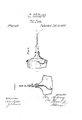
' The invention consists in the application of an elastic tube to the interior of the nozzle of the can, the' tubo being loaded with a weight at its free or disengaged end, as hereialter fallyshonn and described, whereby all of the oil within the can may be expelled from it, and the oil prevented from leaking out of the nozzle in caso the carrbe casually upset. In'the accompanying sheet of drawings-L Figur'o 1 is a central section ol my invention, taken ln the lino xx, lig. 2, and shownin an upright position.
Figure 2, a side sectional view of the same partly in section, and 'shown in an inclined position.
Similar letters of reference indicate like parts.
A represents the body of the can, and B the nozzle,n'hich is screwed into it. These parts maybe constructed in themsual manner, and therefore do not require a specie-l description. C is an elastic tube, vwhich may be constructed oil-India rubber or other suitable elastic material. This tube is inserted in the nozzle B, and snugly packed therein by pressure or otherwise, so as to eliectually prevent leakage between it and the nozzle.
The opposite end ol the tnbc has a weight, D, attached, which is drilled or has a passage, a, made through it to leonnnunicnte with the interior ot the elastic tubo C, as shown clearly in lig. 1. The tube C should beef such a length that when fitted in the nozzle B its weight D may bo allowed to rest upon tho' 'bottom of the can, as shown in iig. 1., and it will be seen that, in conscqnenceof the tube C being flexible, the can can he turned in any position, and the weight D will cause the free or disengaged end of the tube to be in contact with the' lower part of the body of thc can, (see lig. 2;) hence all the oil may be expelled from ths'can through the elastic tube by pressing inward the bottom of thesame, and in onse the can should be upset no oil can leak. I
from the nozzle.
The elastic tubo and weight may be applied to any of the oil-cans in use, and at a very small expense. I would remark that instcadof an entire elastic tubo two rigid ormetallic tubes may bs used, connected together by an elastic or llcxible joint, the lower tube being provided with the weight D. This would be substantially the same as the single flexible tube above described, but the latter would probably be the most desirable.
Having thus described my invention, I clailnas hcw,- and desire te secure by Letters Pateut The elastic-tube C, in combination with tho Inoz'z'lo B, and of such length that the perforated ball D upon i its lower end shall reach either the top/side, 'or bottom of the can A, as herein described for the'purposc specified. i
' CHARLES' WILLIAMS.
Witnesses:
M. G. LANnIs, Gno. P. Janen.
Publications (1)
| Publication Number | Publication Date |
|---|---|
| US69882A true US69882A (en) | 1867-10-15 |
Family
ID=2139402
Family Applications (1)
| Application Number | Title | Priority Date | Filing Date |
|---|---|---|---|
| US69882D Expired - Lifetime US69882A (en) | Improvement in oil-cups |
Country Status (1)
| Country | Link |
|---|---|
| US (1) | US69882A (en) |
Cited By (5)
| Publication number | Priority date | Publication date | Assignee | Title |
|---|---|---|---|---|
| US2583481A (en) * | 1946-01-19 | 1952-01-22 | Dole Valve Co | Vent valve structure |
| US3088680A (en) * | 1960-07-19 | 1963-05-07 | Robert A Fulton | Dispenser for pressurized products |
| US3092107A (en) * | 1960-02-23 | 1963-06-04 | Nathan D Froot | Hypodermic injection device |
| US3485563A (en) * | 1967-09-28 | 1969-12-23 | Alwyn C S Chennell | Fountain type fluid applicator |
| US20200332197A1 (en) * | 2017-09-13 | 2020-10-22 | University Of Wyoming | Systems and methods for refining coal into high value products |
-
0
- US US69882D patent/US69882A/en not_active Expired - Lifetime
Cited By (5)
| Publication number | Priority date | Publication date | Assignee | Title |
|---|---|---|---|---|
| US2583481A (en) * | 1946-01-19 | 1952-01-22 | Dole Valve Co | Vent valve structure |
| US3092107A (en) * | 1960-02-23 | 1963-06-04 | Nathan D Froot | Hypodermic injection device |
| US3088680A (en) * | 1960-07-19 | 1963-05-07 | Robert A Fulton | Dispenser for pressurized products |
| US3485563A (en) * | 1967-09-28 | 1969-12-23 | Alwyn C S Chennell | Fountain type fluid applicator |
| US20200332197A1 (en) * | 2017-09-13 | 2020-10-22 | University Of Wyoming | Systems and methods for refining coal into high value products |
Similar Documents
| Publication | Publication Date | Title |
|---|---|---|
| US69882A (en) | Improvement in oil-cups | |
| US56004A (en) | Improvement in oilers | |
| US69706A (en) | Improvement in hose-ooupling | |
| US80847A (en) | Ok ren l | |
| US474940A (en) | Pocket-case for bottles | |
| US100115A (en) | William-brown | |
| US1208447A (en) | Bottle-stopper. | |
| US65511A (en) | Improvement in steam gauge-cooks | |
| US1236426A (en) | Hypodermic syringe. | |
| US12309A (en) | Fottntainvbrush | |
| US921085A (en) | Oil-can. | |
| US488401A (en) | Faucet | |
| US513608A (en) | Stopper for mucilage-bottles | |
| US67720A (en) | James s | |
| US120668A (en) | Improvement in stop-cocks | |
| US672295A (en) | Cap and filling device for fountain-pens. | |
| US174131A (en) | Improvement in oil-can nozzles | |
| US54707A (en) | Improvement in beer-faucets | |
| US133635A (en) | Improvement in sheet-wietal cans | |
| US1046015A (en) | Bottle-stopper. | |
| US929360A (en) | Fountain-pen. | |
| US66932A (en) | William young | |
| US550231A (en) | Valve | |
| US854618A (en) | Oil or gasolene can. | |
| US105857A (en) | Improvement in safety measuring-funnel |