US6887175B2 - Hybrid transmission - Google Patents
Hybrid transmission Download PDFInfo
- Publication number
- US6887175B2 US6887175B2 US10/445,907 US44590703A US6887175B2 US 6887175 B2 US6887175 B2 US 6887175B2 US 44590703 A US44590703 A US 44590703A US 6887175 B2 US6887175 B2 US 6887175B2
- Authority
- US
- United States
- Prior art keywords
- planetary gearset
- motor
- pinion planetary
- brake
- ring gear
- Prior art date
- Legal status (The legal status is an assumption and is not a legal conclusion. Google has not performed a legal analysis and makes no representation as to the accuracy of the status listed.)
- Expired - Fee Related
Links
Images


Classifications
-
- B—PERFORMING OPERATIONS; TRANSPORTING
- B60—VEHICLES IN GENERAL
- B60K—ARRANGEMENT OR MOUNTING OF PROPULSION UNITS OR OF TRANSMISSIONS IN VEHICLES; ARRANGEMENT OR MOUNTING OF PLURAL DIVERSE PRIME-MOVERS IN VEHICLES; AUXILIARY DRIVES FOR VEHICLES; INSTRUMENTATION OR DASHBOARDS FOR VEHICLES; ARRANGEMENTS IN CONNECTION WITH COOLING, AIR INTAKE, GAS EXHAUST OR FUEL SUPPLY OF PROPULSION UNITS IN VEHICLES
- B60K6/00—Arrangement or mounting of plural diverse prime-movers for mutual or common propulsion, e.g. hybrid propulsion systems comprising electric motors and internal combustion engines
- B60K6/20—Arrangement or mounting of plural diverse prime-movers for mutual or common propulsion, e.g. hybrid propulsion systems comprising electric motors and internal combustion engines the prime-movers consisting of electric motors and internal combustion engines, e.g. HEVs
- B60K6/42—Arrangement or mounting of plural diverse prime-movers for mutual or common propulsion, e.g. hybrid propulsion systems comprising electric motors and internal combustion engines the prime-movers consisting of electric motors and internal combustion engines, e.g. HEVs characterised by the architecture of the hybrid electric vehicle
- B60K6/44—Series-parallel type
- B60K6/445—Differential gearing distribution type
-
- B—PERFORMING OPERATIONS; TRANSPORTING
- B60—VEHICLES IN GENERAL
- B60K—ARRANGEMENT OR MOUNTING OF PROPULSION UNITS OR OF TRANSMISSIONS IN VEHICLES; ARRANGEMENT OR MOUNTING OF PLURAL DIVERSE PRIME-MOVERS IN VEHICLES; AUXILIARY DRIVES FOR VEHICLES; INSTRUMENTATION OR DASHBOARDS FOR VEHICLES; ARRANGEMENTS IN CONNECTION WITH COOLING, AIR INTAKE, GAS EXHAUST OR FUEL SUPPLY OF PROPULSION UNITS IN VEHICLES
- B60K6/00—Arrangement or mounting of plural diverse prime-movers for mutual or common propulsion, e.g. hybrid propulsion systems comprising electric motors and internal combustion engines
- B60K6/20—Arrangement or mounting of plural diverse prime-movers for mutual or common propulsion, e.g. hybrid propulsion systems comprising electric motors and internal combustion engines the prime-movers consisting of electric motors and internal combustion engines, e.g. HEVs
- B60K6/22—Arrangement or mounting of plural diverse prime-movers for mutual or common propulsion, e.g. hybrid propulsion systems comprising electric motors and internal combustion engines the prime-movers consisting of electric motors and internal combustion engines, e.g. HEVs characterised by apparatus, components or means specially adapted for HEVs
- B60K6/36—Arrangement or mounting of plural diverse prime-movers for mutual or common propulsion, e.g. hybrid propulsion systems comprising electric motors and internal combustion engines the prime-movers consisting of electric motors and internal combustion engines, e.g. HEVs characterised by apparatus, components or means specially adapted for HEVs characterised by the transmission gearings
- B60K6/365—Arrangement or mounting of plural diverse prime-movers for mutual or common propulsion, e.g. hybrid propulsion systems comprising electric motors and internal combustion engines the prime-movers consisting of electric motors and internal combustion engines, e.g. HEVs characterised by apparatus, components or means specially adapted for HEVs characterised by the transmission gearings with the gears having orbital motion
-
- B—PERFORMING OPERATIONS; TRANSPORTING
- B60—VEHICLES IN GENERAL
- B60K—ARRANGEMENT OR MOUNTING OF PROPULSION UNITS OR OF TRANSMISSIONS IN VEHICLES; ARRANGEMENT OR MOUNTING OF PLURAL DIVERSE PRIME-MOVERS IN VEHICLES; AUXILIARY DRIVES FOR VEHICLES; INSTRUMENTATION OR DASHBOARDS FOR VEHICLES; ARRANGEMENTS IN CONNECTION WITH COOLING, AIR INTAKE, GAS EXHAUST OR FUEL SUPPLY OF PROPULSION UNITS IN VEHICLES
- B60K6/00—Arrangement or mounting of plural diverse prime-movers for mutual or common propulsion, e.g. hybrid propulsion systems comprising electric motors and internal combustion engines
- B60K6/20—Arrangement or mounting of plural diverse prime-movers for mutual or common propulsion, e.g. hybrid propulsion systems comprising electric motors and internal combustion engines the prime-movers consisting of electric motors and internal combustion engines, e.g. HEVs
- B60K6/42—Arrangement or mounting of plural diverse prime-movers for mutual or common propulsion, e.g. hybrid propulsion systems comprising electric motors and internal combustion engines the prime-movers consisting of electric motors and internal combustion engines, e.g. HEVs characterised by the architecture of the hybrid electric vehicle
- B60K6/48—Parallel type
-
- F—MECHANICAL ENGINEERING; LIGHTING; HEATING; WEAPONS; BLASTING
- F16—ENGINEERING ELEMENTS AND UNITS; GENERAL MEASURES FOR PRODUCING AND MAINTAINING EFFECTIVE FUNCTIONING OF MACHINES OR INSTALLATIONS; THERMAL INSULATION IN GENERAL
- F16H—GEARING
- F16H3/00—Toothed gearings for conveying rotary motion with variable gear ratio or for reversing rotary motion
- F16H3/44—Toothed gearings for conveying rotary motion with variable gear ratio or for reversing rotary motion using gears having orbital motion
- F16H3/72—Toothed gearings for conveying rotary motion with variable gear ratio or for reversing rotary motion using gears having orbital motion with a secondary drive, e.g. regulating motor, in order to vary speed continuously
- F16H3/727—Toothed gearings for conveying rotary motion with variable gear ratio or for reversing rotary motion using gears having orbital motion with a secondary drive, e.g. regulating motor, in order to vary speed continuously with at least two dynamo electric machines for creating an electric power path inside the gearing, e.g. using generator and motor for a variable power torque path
- F16H3/728—Toothed gearings for conveying rotary motion with variable gear ratio or for reversing rotary motion using gears having orbital motion with a secondary drive, e.g. regulating motor, in order to vary speed continuously with at least two dynamo electric machines for creating an electric power path inside the gearing, e.g. using generator and motor for a variable power torque path with means to change ratio in the mechanical gearing
-
- B—PERFORMING OPERATIONS; TRANSPORTING
- B60—VEHICLES IN GENERAL
- B60K—ARRANGEMENT OR MOUNTING OF PROPULSION UNITS OR OF TRANSMISSIONS IN VEHICLES; ARRANGEMENT OR MOUNTING OF PLURAL DIVERSE PRIME-MOVERS IN VEHICLES; AUXILIARY DRIVES FOR VEHICLES; INSTRUMENTATION OR DASHBOARDS FOR VEHICLES; ARRANGEMENTS IN CONNECTION WITH COOLING, AIR INTAKE, GAS EXHAUST OR FUEL SUPPLY OF PROPULSION UNITS IN VEHICLES
- B60K1/00—Arrangement or mounting of electrical propulsion units
- B60K1/02—Arrangement or mounting of electrical propulsion units comprising more than one electric motor
-
- F—MECHANICAL ENGINEERING; LIGHTING; HEATING; WEAPONS; BLASTING
- F16—ENGINEERING ELEMENTS AND UNITS; GENERAL MEASURES FOR PRODUCING AND MAINTAINING EFFECTIVE FUNCTIONING OF MACHINES OR INSTALLATIONS; THERMAL INSULATION IN GENERAL
- F16H—GEARING
- F16H37/00—Combinations of mechanical gearings, not provided for in groups F16H1/00 - F16H35/00
- F16H37/02—Combinations of mechanical gearings, not provided for in groups F16H1/00 - F16H35/00 comprising essentially only toothed or friction gearings
- F16H37/06—Combinations of mechanical gearings, not provided for in groups F16H1/00 - F16H35/00 comprising essentially only toothed or friction gearings with a plurality of driving or driven shafts; with arrangements for dividing torque between two or more intermediate shafts
- F16H37/08—Combinations of mechanical gearings, not provided for in groups F16H1/00 - F16H35/00 comprising essentially only toothed or friction gearings with a plurality of driving or driven shafts; with arrangements for dividing torque between two or more intermediate shafts with differential gearing
- F16H37/10—Combinations of mechanical gearings, not provided for in groups F16H1/00 - F16H35/00 comprising essentially only toothed or friction gearings with a plurality of driving or driven shafts; with arrangements for dividing torque between two or more intermediate shafts with differential gearing at both ends of intermediate shafts
- F16H2037/103—Power-split transmissions with each end of a CVT connected or connectable to a planetary gear set having four or more connections, e.g. a Ravigneaux set
-
- F—MECHANICAL ENGINEERING; LIGHTING; HEATING; WEAPONS; BLASTING
- F16—ENGINEERING ELEMENTS AND UNITS; GENERAL MEASURES FOR PRODUCING AND MAINTAINING EFFECTIVE FUNCTIONING OF MACHINES OR INSTALLATIONS; THERMAL INSULATION IN GENERAL
- F16H—GEARING
- F16H2200/00—Transmissions for multiple ratios
- F16H2200/20—Transmissions using gears with orbital motion
- F16H2200/2002—Transmissions using gears with orbital motion characterised by the number of sets of orbital gears
- F16H2200/2005—Transmissions using gears with orbital motion characterised by the number of sets of orbital gears with one sets of orbital gears
-
- F—MECHANICAL ENGINEERING; LIGHTING; HEATING; WEAPONS; BLASTING
- F16—ENGINEERING ELEMENTS AND UNITS; GENERAL MEASURES FOR PRODUCING AND MAINTAINING EFFECTIVE FUNCTIONING OF MACHINES OR INSTALLATIONS; THERMAL INSULATION IN GENERAL
- F16H—GEARING
- F16H2200/00—Transmissions for multiple ratios
- F16H2200/20—Transmissions using gears with orbital motion
- F16H2200/2002—Transmissions using gears with orbital motion characterised by the number of sets of orbital gears
- F16H2200/2007—Transmissions using gears with orbital motion characterised by the number of sets of orbital gears with two sets of orbital gears
-
- F—MECHANICAL ENGINEERING; LIGHTING; HEATING; WEAPONS; BLASTING
- F16—ENGINEERING ELEMENTS AND UNITS; GENERAL MEASURES FOR PRODUCING AND MAINTAINING EFFECTIVE FUNCTIONING OF MACHINES OR INSTALLATIONS; THERMAL INSULATION IN GENERAL
- F16H—GEARING
- F16H2200/00—Transmissions for multiple ratios
- F16H2200/20—Transmissions using gears with orbital motion
- F16H2200/202—Transmissions using gears with orbital motion characterised by the type of Ravigneaux set
- F16H2200/2025—Transmissions using gears with orbital motion characterised by the type of Ravigneaux set using a Ravigneaux set with 5 connections
-
- Y—GENERAL TAGGING OF NEW TECHNOLOGICAL DEVELOPMENTS; GENERAL TAGGING OF CROSS-SECTIONAL TECHNOLOGIES SPANNING OVER SEVERAL SECTIONS OF THE IPC; TECHNICAL SUBJECTS COVERED BY FORMER USPC CROSS-REFERENCE ART COLLECTIONS [XRACs] AND DIGESTS
- Y02—TECHNOLOGIES OR APPLICATIONS FOR MITIGATION OR ADAPTATION AGAINST CLIMATE CHANGE
- Y02T—CLIMATE CHANGE MITIGATION TECHNOLOGIES RELATED TO TRANSPORTATION
- Y02T10/00—Road transport of goods or passengers
- Y02T10/60—Other road transportation technologies with climate change mitigation effect
- Y02T10/62—Hybrid vehicles
-
- Y—GENERAL TAGGING OF NEW TECHNOLOGICAL DEVELOPMENTS; GENERAL TAGGING OF CROSS-SECTIONAL TECHNOLOGIES SPANNING OVER SEVERAL SECTIONS OF THE IPC; TECHNICAL SUBJECTS COVERED BY FORMER USPC CROSS-REFERENCE ART COLLECTIONS [XRACs] AND DIGESTS
- Y10—TECHNICAL SUBJECTS COVERED BY FORMER USPC
- Y10S—TECHNICAL SUBJECTS COVERED BY FORMER USPC CROSS-REFERENCE ART COLLECTIONS [XRACs] AND DIGESTS
- Y10S903/00—Hybrid electric vehicles, HEVS
- Y10S903/902—Prime movers comprising electrical and internal combustion motors
- Y10S903/903—Prime movers comprising electrical and internal combustion motors having energy storing means, e.g. battery, capacitor
- Y10S903/904—Component specially adapted for hev
- Y10S903/909—Gearing
- Y10S903/91—Orbital, e.g. planetary gears
-
- Y—GENERAL TAGGING OF NEW TECHNOLOGICAL DEVELOPMENTS; GENERAL TAGGING OF CROSS-SECTIONAL TECHNOLOGIES SPANNING OVER SEVERAL SECTIONS OF THE IPC; TECHNICAL SUBJECTS COVERED BY FORMER USPC CROSS-REFERENCE ART COLLECTIONS [XRACs] AND DIGESTS
- Y10—TECHNICAL SUBJECTS COVERED BY FORMER USPC
- Y10S—TECHNICAL SUBJECTS COVERED BY FORMER USPC CROSS-REFERENCE ART COLLECTIONS [XRACs] AND DIGESTS
- Y10S903/00—Hybrid electric vehicles, HEVS
- Y10S903/902—Prime movers comprising electrical and internal combustion motors
- Y10S903/903—Prime movers comprising electrical and internal combustion motors having energy storing means, e.g. battery, capacitor
- Y10S903/904—Component specially adapted for hev
- Y10S903/915—Specific drive or transmission adapted for hev
- Y10S903/917—Specific drive or transmission adapted for hev with transmission for changing gear ratio
- Y10S903/919—Stepped shift
-
- Y—GENERAL TAGGING OF NEW TECHNOLOGICAL DEVELOPMENTS; GENERAL TAGGING OF CROSS-SECTIONAL TECHNOLOGIES SPANNING OVER SEVERAL SECTIONS OF THE IPC; TECHNICAL SUBJECTS COVERED BY FORMER USPC CROSS-REFERENCE ART COLLECTIONS [XRACs] AND DIGESTS
- Y10—TECHNICAL SUBJECTS COVERED BY FORMER USPC
- Y10S—TECHNICAL SUBJECTS COVERED BY FORMER USPC CROSS-REFERENCE ART COLLECTIONS [XRACs] AND DIGESTS
- Y10S903/00—Hybrid electric vehicles, HEVS
- Y10S903/902—Prime movers comprising electrical and internal combustion motors
- Y10S903/903—Prime movers comprising electrical and internal combustion motors having energy storing means, e.g. battery, capacitor
- Y10S903/945—Characterized by control of gearing, e.g. control of transmission ratio
Definitions
- the present invention relates to a hybrid transmission which is applicable to a hybrid vehicle equipped with a plurality of power sources such as an internal combustion engine and a motor/generator, and more particularly to a continuously variable hybrid transmission which is capable of continuously varying a transmission ratio using a differential mechanism.
- JP-A-2000-142146 discloses a hybrid transmission for a hybrid vehicle.
- This hybrid transmission employs a two-degree-of-freedom differential device including three rotating elements which are connected to an input from an engine, an output to a driveline and a motor/generator, respectively.
- this hybrid transmission has a limitation in selecting a high-side transmission ratio such as an overdrive transmission ratio due to a structural limitation of this hybrid transmission. That is, if this hybrid transmission is arranged to be selectable of the overdrive, the use of the overdrive requires increasing the load of the motor/generator and thereby requiring a larger motor/generator or disaffecting fuel consumption.
- An aspect of the present invention resides in a hybrid transmission which is for a hybrid vehicle and comprises a differential mechanism including at least five rotating members, the rotating members being interlinked so that rotating conditions of all of the rotating members are determined when rotating conditions of two of the rotating members are determined, four of the rotating members being connected to an input from a main power source, an output to a driveline, first and second mover/generators, respectively; and a brake connected to one of the rotating members, the brake being capable of being put in an engaged state to brake the one of the rotating members; wherein an absolute value of a revolution speed of the rotating member connected to the output is greater than an absolute value of a revolution speed of the rotating member connected to the input when the brake is put in the engaged state.
- the hybrid transmission comprising a two-degree-of-freedom differential mechanism including at least five rotating members, the rotating members being interlinked so that rotating conditions of all of the rotating members are determined when rotating conditions of two of the rotating members are determined, five of the rotating members being connected to a first motor/generator, one of a brake and an output to a driveline, an input from a main power source, the other of the brake and the output to the driveline, and a second motor/generator, respectively, in the sequence of revolution speeds of the five rotating members.
- a further another aspect of the present invention resides in a hybrid transmission for a hybrid vehicle, comprising: a two-degree-of-freedom differential mechanism including at least six rotating members, the rotating members being interlinked so that rotating conditions of all of the rotating members are determined when rotating conditions of two of the rotating members are determined, six of the rotating members being connected to a second motor/generator, a first brake, an input from a main power source, an output to the driveline, a second brake and a first motor/generator, respectively, in the sequence of revolution speeds of the five rotating members.
- FIG. 1A is a cross-sectional view showing a first embodiment of a hybrid transmission according to the present invention.
- FIG. 1B is a lever diagram of the hybrid transmission of FIG. 1 A.
- FIG. 2 is a cross-sectional view showing a second embodiment of the hybrid transmission according to the present invention.
- FIG. 3A is a cross-sectional view showing a third embodiment of the hybrid transmission according to the present invention.
- FIG. 3B is a lever diagram of the hybrid transmission of FIG. 3 A.
- FIG. 4A is a cross-sectional view showing a fourth embodiment of the hybrid transmission according to the present invention.
- FIG. 4B is a lever diagram of the hybrid transmission of FIG. 4 A.
- FIG. 5 is a cross-sectional view showing a fifth embodiment of the hybrid transmission according to the present invention.
- FIG. 6A is a cross-sectional view showing a sixth embodiment of the hybrid transmission according to the present invention.
- FIG. 6B is a lever diagram of the hybrid transmission of FIG. 6 A.
- FIG. 7A is a cross-sectional view showing a seventh embodiment of the hybrid transmission according to the present invention.
- FIG. 7B is a lever diagram of the hybrid transmission of FIG. 7 A.
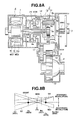
- FIG. 8A is a cross-sectional view showing an eighth embodiment of the hybrid transmission according to the present invention.
- FIG. 8B is a lever diagram of the hybrid transmission of FIG. 8 A.
- FIG. 9A is a cross-sectional view showing a ninth embodiment of the hybrid transmission according to the present invention.
- FIG. 9B is a lever diagram of the hybrid transmission of FIG. 9 A.
- FIG. 10 is a flowchart showing an engagement control program of an overdrive brake of the hybrid transmission throughout FIGS. 1A through 9B .
- FIG. 11 is a flowchart showing a disengagement control program of the overdrive brake of the hybrid transmission throughout FIGS. 1 A through 9 B.
- FIGS. 1A through 11 there are shown embodiments of a hybrid transmission according to the present invention.
- FIGS. 1A and 1B show a first embodiment of the hybrid (automatic) transmission according to the present invention.
- the hybrid transmission is adapted to a transaxle of a front-wheel-drive vehicle.
- the hybrid transmission of the first embodiment comprises a transmission case 1 , a Ravigneaux planetary gearset 2 , and a compound-current double-layer motor 4 constructing first and second motor/generators MG 1 and MG 2 .
- Ravigneaux planetary gearset 2 is built in transmission case 1 so as to be located at a left-hand side of an internal combustion engine (prime mover) 3 along an axial direction of transmission case 1 in FIG. 1 A.
- compound-current double-layer motor 4 is built in a transmission case 1 so as to be located at the left-hand side of Ravigneaux planetary gearset 2 along the axial direction of transmission case 1 in FIG. 1 A.
- Ravigneaux planetary gearset 2 , engine 3 and compound-current double-layer motor 4 are coaxially arranged on a main axis of transmission case 1 .
- a counter shaft 5 and a differential gear device 6 are also built in transmission case 1 so as to be parallel with the main axis while being offset from the main axis.
- Ravigneaux planetary gearset 2 is of a compound planetary gear train where a single-pinion planetary gearset 7 is combined with a double-pinion planetary gearset 8 , and common pinions P 1 and a common ring gear Rs are commonly employed in two planetary gearsets 7 and 8 .
- Single-pinion planetary gearset 7 is located near engine 3 than double-pinion planetary gearset 8
- double-pinion planetary gearset 8 is located near compound-current double-layer motor 4 .
- Single-pinion planetary gearset 7 comprises a sun gear Ss, common ring gear Rs and common pinions P 1 in meshed-engagement with both sun gear Ss and common ring gear Rs.
- Double-pinion planetary gearset 8 comprises a sun gear Sd, common pinions P 1 , common ring gear Rs, a ring gear Rd, and large-diameter pinions P 2 .
- Large-diameter pinions P 2 are in mesh-engagement with sun gear Sd, ring gear Rd and common pinions P 1 .
- Pinions P 1 and P 2 of the two planetary gearsets 7 and 8 are rotatably mounted or supported on shafts that integrally project from a common pinion carrier C.
- Ravigneaux planetary gearset 2 is mainly constituted by five rotating members (five rotating elements), that is, sun gear Ss, sun gear Sd, ring gear Rs, ring gear Rd and pinion carrier C.
- Ravigneaux planetary gearset 2 is a two-degree-of-freedom differential mechanism having five rotating elements.
- the sequence of revolution speeds of the rotating members is arranged in the sequence of sun gear Sd, ring gear Rs, carrier C, ring gear Rd and sun gear Ss from a high revolution speed side.
- Ravigneaux planetary gearset 2 employed in this first embodiment is equivalent to a gearset which is arranged such that a ring gear of single-pinion planetary gearset 7 is connected to a ring gear of double-pinion planetary gearset 8 , and a carrier of single-pinion planetary gearset 7 is connected to a carrier of double-pinion planetary gearset 8 .
- Such a gearset having five elements and performing the two-degree-of-freedom may be constructed by combining three of single-pinion planetary gearsets constructed by nine rotating elements and by connecting these three single-pinion planetary gearsets at four portions without connecting a rotating member and another rotating member.
- Compound-current double-layer motor 4 comprises an inner rotor 4 ri, an annular outer rotor 4 ro surrounding inner rotor 4 ri and a stator coil 4 s.
- Inner and outer rotors 4 ri and 4 ro are coaxially arranged with each other at the rear axial end (the left-hand end) of transmission case 1 and rotatably supported in transmission case 1 .
- Annular stator coil 4 s acting as a stator of compound-current double-layer motor 4 is disposed in an annular space defined between the outer periphery of inner rotor 4 ri and the inner periphery of outer rotor 4 ro and fixedly connected to transmission case 1 .
- Annular stator coil 4 s and inner rotor 4 ri construct an inner motor/generator (first motor/generator) MG 1
- annular stator coil 4 s and outer rotor 4 ro construct an outer motor/generator (second motor/generator) MG 2 .
- a compound multiphase alternating current (AC) multi-layer (double-layer) motor 4 which has multiple motors (two rotors in this embodiment) and is driven by compound multiphase AC, is employed as first and second motor/generator MG 1 and MG 2 .
- compound-current double-layer motor 4 is arranged such that the number of pole pairs of inner rotor 4 ri is different from the number of pole pairs of outer rotor 4 ro.
- Inner and outer rotors 4 ri and 4 ro of first and second motor/generators MG 1 and MG 2 are therefore driven independently of each other in revolution speed and in revolution direction by compounding a control current applied to one of the motor/generator set and a control current applied to the other.
- each of motor/generators MG 1 and MG 2 functions as an electric motor which outputs a rotational force having a revolution direction corresponding to a current direction and a revolution speed corresponding to a current strength of the supplied current.
- each of first and second motor/generators MG 1 and MG 2 functions as a generator which outputs an electric power corresponding to the magnitude of torque applied by way of an external force.
- sun gear Sd, ring gear Rs, carrier C, ring gear Rd, and sun gear Ss which are five rotating members of Ravigneaux planetary gearset 2 , are connected to first motor/generator MG 1 (inner rotor 4 ri), an overdrive brake OD/B for selecting an overdrive position, an input IN connected to engine 3 , an output OUT connected to a wheel driveline and second motor/generator MG 2 (outer rotor 4 ro), respectively.
- This mentioned sequence of the five rotating members are arranged in the sequence of the revolution speeds from the highest revolution speed.
- Carrier C acts as an input element through which the power of engine 3 is inputted to the hybrid transmission. That is, carrier C is connected to a crankshaft of engine 3 through an input shaft 10 of the hybrid transmission.
- a one-way clutch OWC for preventing a reverse revolution against the revolution of engine 3 is provided between transmission input shaft 10 and transmission case 1 .
- Sun gear Sd is connected to first motor/generator MG 1 (inner rotor 4 ri) through a hollow shaft 13 .
- Sun gear Ss is connected to second motor/generator MG 2 (outer rotor 4 ro) through a shaft 14 which is rotatably supported by first motor/generator MG 1 and hollow shaft 13 .
- Overdrive brake OD/B is connected to ring gear Rs so that ring gear Rs is braked at a desired period through the engagement operation of overdrive brake OD/B.
- ring gear Rd In order to operate ring gear Rd as an output element for outputting the revolution to the wheel drive line, ring gear Rd is connected to an output gear 16 through a connecting member 15 of a stepped hollow structure, and output gear 16 is mesh-engaged with a counter gear 17 integrally connected to a counter shaft 5 which is rotatably supported by transmission case 1 .
- Counter gear 17 is disposed between Ravigneaux planetary gearset 2 and compound-current double-layer motor 4 .
- a final-drive pinion 18 is also integrally connected to counter shaft 5 and is mesh-engaged with a final-drive ring gear 19 provided in a differential gear device 6 .
- the transmission output revolution outputted from output gear 16 is transmitted to final differential gear device 6 through a final drive gearset constructed by final drive pinion 18 and final drive ring gear 19 , and is distributed to the right and left wheels (not shown) through final differential device 6 .
- This transmitting line constitutes a wheel driveline.
- the hybrid transmission of the first embodiment achieves the shift operation represented by the lever diagram in FIG. 1B as follows.
- the hybrid transmission realizes the overdrive transmission ratio by fixing ring gear Rs which is located opposite to output OUT through input IN in the lever diagram of FIG. 1 B. That is, the overdrive transmission ratio is achieved without excessively increasing a load to first and second motor/generators MG 1 and MG 2 in view of a lever ratio of the lever diagram of FIG. 1 B.
- This overdrive transmission ratio by this arrangement does not require increasing the capacity of first and second motor/generators MG 1 and MG 2 , and enables the improvement of fuel consumption by the proper selection of the high-speed side transmission ratio, while avoiding the influence to the fuel consumption.
- generative maximum driving force varies according to whether overdrive brake OD/B is in an engaged state or in a disengaged state. More specifically, the generative maximum driving force under the engaged state of overdrive brake OD/B is greater than that under the disengaged state of overdrive brake OD/B.
- the flowchart of FIG. 10 discloses a control executed for changing the state of overdrive brake OD/B from the engaged state to the disengaged state.
- first and second motor/generators MG 1 and MG 2 is controlled in driving force so as to bring the revolution speed of the brake element (ring gear Rs in the first embodiment) braked by overdrive brake OD/B closer to zero.
- This operation corresponds to the processing at step S 40 of FIG. 10 .
- the engagement operation of overdrive brake OD/B is executed.
- This operation corresponds to the processing at step S 50 . That is, when the affirmative determination is made at all of steps S 10 , S 20 and S 30 , the program proceeds to step S 40 .
- steps S 40 and S 50 the engagement of overdrive brake OD/B is executed without generating the relative revolution of the brake, and thereby eliminating the shock due to the engagement of overdrive brake OD/B.
- the flowchart of FIG. 11 represents a control for changing the state of overdrive brake OD/B from the engaged state to the disengaged state.
- overdrive brake OD/B When it is determined that the vehicle is traveling under the engaged state of overdrive brake OD/B (the affirmative determination at step S 110 ) and when it is determined that overdrive brake OD/B should be disengaged (the affirmative determination at step S 120 ), that is, when a request for changing a transmission ratio except for the overdrive transmission ratio is generated, the disengagement of overdrive brake OD/B is executed as follows.
- first and second motor/generators MG 1 and MG 2 is controlled in driving force so as to maintain the revolution speed of the brake element (ring gear Rs in the first embodiment) braked by overdrive brake OD/B at zero even if overdrive brake OD/B is disengaged.
- This operation corresponds to the processing at step S 130 .
- the disengagement operation of overdrive brake OD/B is executed. This operation corresponds to the processing at step S 140 .
- steps S 130 and S 140 the disengagement of overdrive brake OD/B is executed without generating the relative revolution of the brake, and thereby eliminating the shock due to the disengagement of overdrive brake OD/B.
- first and second motor/generators MG 1 and MG 2 in an inoperative state under the engaged state of overdrive brake OD/B, it becomes possible to operate first and second motor/generators MG 1 and MG 2 while adjusting the electric balance therebetween.
- first motor/generator MG 1 as a generator (in the reverse revolution state) and by operating second motor/generator MG 2 as a motor (in the right revolution), it is possible to operate first and second motor/generators MG 1 and MG 2 while adjusting the electric balance therebetween.
- second motor/generating MG 2 functioning as a motor with respect to that of first motor/generator MG 1 functioning as a generator or by operating both of first and second motor/generators as motors, it becomes possible to output the power greater than the power generated by engine 3 .
- the hybrid transmission can take two operating points (specific input output revolution ratio) where one of first and second motor/generators MG 1 and MG 2 is stopped (put in zero revolution speed). At these input-output revolution ratios (transmission ratios), the hybrid transmission can operate without consuming electric power.
- the hybrid transmission according to the present invention enables the vehicle to operate as an electric vehicle.
- the hybrid transmission when the hybrid transmission is in a shift condition represented by the lever REV of the lever diagram in FIG. 1B , a reverse revolution is outputted from ring gear Rd to output OUT. That is, the hybrid transmission is in a backward revolution (reverse revolution) output condition. Under this condition, it is possible to drive first motor/generator MG 1 in the right revolution output direction and to drive second motor/generator MG 1 in the reverse revolution output direction while one-way clutch OWC performs the reverse revolution preventing function.
- FIG. 2 shows a second embodiment of the hybrid transmission according to the present invention.
- the hybrid transmission is also adapted to a transaxle for a front-engine front-drive vehicle (FF vehicle).
- FF vehicle front-engine front-drive vehicle
- single-pinion planetary gearset 7 of Ravigneaux planetary gearset 2 is located near compound-current double-layer motor 4 and apart from engine 3
- double-pinion planetary gearset 8 of Ravigneaux planetary gearset 2 is located near engine 3 .
- first motor/generator MG 1 inner rotor 4 ri
- overdrive brake OD/B for selecting the overdrive position
- input IN connected to engine 3
- output OUT connected to the wheel driveline
- second motor/generator MG 2 output rotor 4 ro
- a carrier C is connected to the crankshaft of engine 3 through a transmission input shaft 10 , and a one-way clutch OWC for preventing a reverse revolution against the revolution of engine 3 is provided between transmission input shaft 10 and transmission case 1 .
- Sun gear Ss is connected to second motor/generator MG 2 (outer rotor 4 ro) through a hollow shaft 13 .
- Sun gear Sd is connected to first motor/generator MG 1 (inner rotor 4 ri) through a shaft 14 which is rotatably supported by hollow shaft 13 .
- a hollow shaft portion 21 extends from ring gear Rs toward compound-current double-layer motor 4 .
- Overdrive brake OD/B is connected through hollow shaft portion 21 to ring gear Rs so that ring gear Rs is braked at a desired period through the engagement operation of overdrive brake OD/B.
- Hollow shaft portion 21 is rotatably supported by transmission case 1 and rotatably supports an output gear 16 disposed between compound-current double-layer motor 4 and Ravigneaux planetary gearset 2 .
- Output gear 16 is connected to ring gear Rd through a connecting member 22 so that the transmission output revolution is outputted from final differential device 5 through output gear 16 , a counter gear 17 , a final drive pinion 18 and a final drive ring gear 19 .
- the hybrid transmission arranged as discussed above, is represented by the lever diagram shown in FIG. 1B , and executes the shift operation as same as that in the first embodiment, and ensures the advantages as same as that gained in the first embodiment.
- overdrive brake OD/B is located between Ravigneaux planetary gearset 2 and compound-current double-layer motor 4 .
- overdirve brake OD/B is located between Ravigneaux planetary gearset 2 and engine 3 . It will be understood that the selecting one arrangement from the first and second embodiments may be freely determined according to the easiness of ensuring a space for providing overdirve brake OD/B.
- FIG. 3A shows a third embodiment of the hybrid transmission according to the present invention.
- the hybrid transmission is also adapted to a transaxle for a front-engine front-drive vehicle (FF vehicle) as is similar to those shown in FIGS. 1 a and 2 .
- FF vehicle front-engine front-drive vehicle
- single-pinion planetary gearset 7 of Ravigneaux planetary gearset 2 is located near compound-current double-layer motor 4 and apart from engine 3
- double-pinion planetary gearset 8 of Ravigneaux planetary gearset 2 is located near engine 3 , as is similar to the arrangement of FIG. 2 .
- the revolution speeds of five rotating members of sun gear Ss, sun gear Sd, ring gear Rs, ring gear Rd and carrier C of Ravigneaux planetary gearset 2 are set to be arranged in the order of mention.
- the arrangement in view of the revolution speed is the same as that shown by the lever diagram in FIG. 1 B. That is, they are arranged in the sequence of sun gear Sd, ring gear Rs, carrier C, ring gear Rd and sun gear Ss.
- first motor/generator MG 2 (outer rotor 4 ro), output OUT connected to the wheel driveline, input IN connected to engine 3 , overdrive brake OD/B for selecting the overdrive position, and first motor/generator MG 1 (inner rotor 4 ri) are connected respectively, as shown in FIG. 3 B.
- Carrier C is connected to the crankshaft of engine 3 through transmission input shaft 10 , and one-way clutch OWC for preventing a reverse revolution against the revolution of engine 3 is provided between transmission input shaft 10 and transmission case 1 .
- Sun gear Ss is connected to first motor/generator MG 1 (inner rotor 4 ri) through a hollow shaft 13 .
- Sun gear Sd is connected to second motor/generator MG 2 (inner rotor 4 ro) through a shaft 14 which is rotatably supported by hollow shaft 13 .
- a connecting member 24 extends from ring gear Rs toward compound-current double-layer motor 4 .
- Ring gear Rs is connected through connecting member 24 to output gear 16 which is located between Ravigneaux planetary gearset 2 and compound-current double-layer motor 4 , and which is rotatably supported by transmission case 1 .
- Overdrive brake OD/B is disposed between Ravigneaux planetary gearset 2 and engine 3 and is connected to ring gear Rd so that ring gear Rs is braked at a desired period through the engagement operation of overdrive brake OD/B.
- the hybrid transmission of the third embodiment achieves the shift operation represented by the lever diagram in FIG. 3B as follows.
- the hybrid transmission realizes the overdrive transmission ratio by fixing ring gear Rd which is located opposite to output OUT through input IN in the lever diagram of FIG. 3 B. That is, the overdrive transmission ratio is achieved without excessively increasing a load to first and second motor/generators MG 1 and MG 2 in view of a lever ratio of the lever diagram of FIG. 3 B.
- This overdrive transmission ratio by this arrangement does not require increasing the capacity of first and second motor/generators MG 1 and MG 2 , and enables the improvement of fuel consumption by the proper selection of the high-speed side transmission ratio, while avoiding the influence to the fuel consumption.
- generative maximum driving force varies according to whether overdrive brake OD/B is in an engaged state or in a disengaged state. More specifically, the generative maximum driving force under the engaged state of overdrive brake OD/B is greater than that under the disengaged state of overdrive brake OD/B.
- first and second motor/generators MG 1 and MG 2 in an inoperative state under the engaged state of overdrive brake OD/B, it becomes possible to operate first and second motor/generators MG 1 and MG 2 under a condition of adjusting the electric balance therebetween.
- first motor/generator MG 1 as a generator (in the reverse revolution state) and by operating second motor/generator MG 2 as a motor (in the right revolution), it is possible to operate first and second motor/generators MG 1 and MG 2 while adjusting the electric balance therebetween.
- second motor/generating MG 2 functioning as a motor with respect to that of first motor/generator MG 1 functioning as a generator or by operating both of first and second motor/generators as motors, it becomes possible to output the power greater than the power generated by engine 3 .
- the hybrid transmission can take two operating points (specific input output revolution ratio) where one of first and second motor/generators MG 1 and MG 2 is stopped (put in zero revolution speed). At these input-output revolution ratios, the hybrid transmission can operate without consuming electric power.
- the hybrid transmission according to the present invention enables the vehicle to operate as an electric vehicle.
- the hybrid transmission when the hybrid transmission is in a shift condition represented by the lever REV of the lever diagram in FIG. 1B , a reverse revolution is outputted from ring gear Rs to output OUT. That is, the hybrid transmission is in a backward revolution (reverse revolution) output condition. Under this condition, it is possible to drive first motor/generator MG 1 in the right revolution output direction and to drive second motor/generator MG 1 in the reverse revolution output direction while one-way clutch OWC performs the reverse revolution preventing function.
- FIG. 4A shows a fourth embodiment of the hybrid transmission according to the present invention.
- Single-pinion planetary gearset 7 and double-pinion planetary gearset 8 of Ravigneaux planetary gearset 2 of this fourth embodiment are arranged as same as those of the first embodiment shown in FIG. 1 A. That is, single-pinion planetary gearset 7 is disposed near engine 3 , and double-pinion planetary gearset 8 is disposed apart from engine 3 .
- Ravigneaux planetary gearset 2 is connected to first and second motor/generators MG 1 and MG 2 such that sun gear Sd is connected to second motor/generator MG 2 (outer rotor 4 ro) through hollow shaft 13 and that sun gear Ss is connected to first motor/generator MG 1 (inner rotor 4 ro) through shaft 14 rotatably supporting hollow shaft 13 .
- the connection relationship between the other rotating members of Ravigneaux planetary gearset 2 and elements connected to Ravigneaux planetary gearset 2 is completely the same as those in the first embodiment shown in FIG. 1 A.
- the lever diagram of the hybrid transmission shown in FIG. 4A is basically similar to that of FIG. 1B except that first and second motor/generators MG 1 and MG 2 are exchanged in position and operation. Therefore, the hybrid transmission of FIG. 4A performs the advantages similar to those gained by the first embodiment.
- FIG. 5 shows a fifth embodiment of the hybrid transmission.
- single-pinion planetary gearset 7 and double-pinion planetary gearset 8 of Ravigneaux planetary gearset 2 are arranged as same as those of the second embodiment shown in FIG. 2 such that single-pinion planetary gearset 7 is disposed apart from engine 3 , and that double-pinion planetary gearset 8 is disposed near engine 3 .
- sun gear Ss is connected to first motor/generator MG 1 (inner rotor 4 ri) through hollow shaft 12
- sun gear Sd is connected to second motor/generator MG 2 (outer rotor 4 ro) through shaft 14 rotatably supporting hollow shaft 13 .
- the connectional relationships between the other rotating members of Ravigneaux planetary gearset 2 and elements connected to Ravigneaux planetary gearset 2 is completely the same as those in the second embodiment shown in FIG. 2 .
- the lever diagram of the hybrid transmission shown in FIG. 5 is basically the same as that of FIG. 1B except that first and second motor/generators MG 1 and MG 2 are exchanged in position and operation. Therefore, the hybrid transmission of FIG. 5 performs the advantages similar to those gained by the first embodiment.
- FIGS. 6A and 6B show a sixth embodiment of the hybrid transmission according to the present invention.
- the hybrid transmission is adapted to a transaxle of a front-wheel-drive vehicle.
- the hybrid transmission of the sixth embodiment newly comprises a smiple planetary gearset 25 which is disposed between Ravigneaux planetary gearset 2 and a compound-current double-layer motor 4 .
- Double-pinion planetary gearset 8 of Ravigneaux planetary gearset 2 is located near engine 3 , and single-pinion planetary gearset 7 is located apart from engine 3 as is clearly shown in FIG. 6 A.
- Single-pinion planetary gearset 7 is configured such that pinions P 1 are in mesh-engagement with sun gear Ss and ring gear Rs, and that ring gear Rs is disposed near engine 3 as compared with double-pinion planetary gearset 8 and is connected to overdrive brake OD/B (first brake).
- Double-pinion planetary gearset 8 comprises sun gear Sd, ring gear Rs, long pinions P 1 , ring gear Rd and large-diameter pinions Ps.
- pinions Ps are in mesh-engagement with sun gear Sd, ring gear Rd and long pinions P 1 . All of pinions P 1 and P 2 of planetary gearsets 7 and 8 are rotatably supported by common carrier C.
- Simple planetary gear 25 added in this sixth embodiment is configured such that a plurality of pinions Po are in mesh-engagement with a sun gear So and a ring gear Ro and are rotatably supported by a carrier Co.
- Ring gear Ro is integrally connected to ring gear Rd, and an output gear 16 is integrally formed on an outer periphery of ring gear Ro.
- Carrier Co is connected to sun gear Ss, and a start brake ST/B (second brake), which is engaged when the vehicle starts to run, is capable of properly fixing this connected member of carrier Co and sun gear Ss to stop the rotation thereof.
- Carrier C is connected to the crankshaft of engine 3 through transmission input shaft 10 to receive the engine revolution. Further, one-way clutch OWC is provided around the transmission input shaft 10 to prevent the revolution reverse against the engine revolution.
- Sun gear So is connected to second motor/generator MG 2 (outer rotor 4 ro) through hollow shaft 13
- sun gear Sd is connected to first motor/generator MG 1 (inner rotor 4 ri) through shaft 14 rotatably supporting hollow shaft 13 .
- the differential apparatus constructed by the combination of Ravigneaux planetary gearset 2 and simple planetary gearset 25 is mainly constituted by six rotating members (six elements), that is, sun gear Ss, sun gear Sd, sun gear So, ring gear Rs, ring gear Rd and carrier C.
- rotating members that is, sun gear Ss, sun gear Sd, sun gear So, ring gear Rs, ring gear Rd and carrier C.
- the combination of Ravigneaux planetary gearset 2 and simple planetary gear 25 is a two-degree-of-freedom differential mechanism having six elements.
- the sequence of revolution speeds of the rotating members is arranged in the sequence of sun gear Sd, ring gear Rs, carrier C, ring gear Rd, sun gear Ss and sun gear So from a high revolution speed side. Further, these rotating members arranged in the sequence of the revolution speed are connected to first motor/generator MG 1 , overdrive brake OD/B, input IN connected to engine 3 , output OUT connected to the wheel driveline, start brake ST/B, and second motor/generator MG 2 , respectively.
- Output gear 16 is integrally formed on an outer periphery of ring gear Ro and is in mesh-engagement with counter gear 17 integrally formed on counter shaft 5 .
- Final-drive pinion 18 is also integrally connected to counter shaft 5 and is mesh-engaged with a final-drive ring gear 19 provided in a differential gear device 6 .
- the transmission output revolution outputted from output gear 16 is transmitted to final differential gear device 6 through a final drive gearset constructed by final drive pinion 18 and final drive ring gear 19 , and is distributed to the right and left wheels (not shown) by means of final differential device 6 .
- This transmitting line constitutes a wheel driveline.
- the hybrid transmission of the sixth embodiment achieves the shift operation represented by the lever diagram in FIG. 6B as follows.
- start brake ST/B is located opposite to input IN with respect to output OUT, and is engaged to fix sun gear Ss (carrier Co).
- sun gear Ss carrier Co
- the hybrid transmission realizes the overdrive transmission ratio by fixing ring gear Rs which is located opposite to output OUT through input IN in the lever diagram of FIG. 1 B. That is, the overdrive transmission ratio is achieved without excessively increasing a load to first and second motor/generators MG 1 and MG 2 in view of a lever ratio of the lever diagram of FIG. 6 B.
- This overdrive transmission ratio by this arrangement does not require increasing the capacity of first and second motor/generators MG 1 and MG 2 , and enables the improvement of fuel consumption by the proper selection of the high-speed side transmission ratio, while avoiding the influence to the fuel consumption.
- the hybrid transmission according to the present invention enables the vehicle as an electric vehicle.
- the hybrid transmission when the hybrid transmission is in a shift condition represented by the lever REV of the lever diagram in FIG. 6B , a reverse revolution is outputted from ring gear Rd to output OUT. That is, the hybrid transmission REV is in a backward revolution (reverse revolution) output condition. Under this condition, it is possible to drive first motor/generator MG 1 in the right revolution output direction and to drive second motor/generator MG 1 in the reverse revolution output direction while one-way clutch OWC performs the reverse revolution preventing function.
- FIG. 7A discloses a seventh embodiment of the hybrid transmission adapted to a transaxle for a front-engine front-drive vehicle (FF vehicle) in accordance with the present invention.
- single-pinion planetary gearset 7 and double-pinion planetary gearset 8 of Ravigneaux planetary gearset 2 are arranged as same as those of the sixth embodiment shown in FIG. 6 A. Further, a smiple planetary gearset 25 is disposed between Ravigneaux planetary gearset 2 and a compound-current double-layer motor 4 .
- Simple planetary gearset 25 and Ravigneaux planetary gearset 2 are combinated as follows.
- Ring gear Rs of single-pinion planetary gearset 7 is disposed at a nearer-side of engine 3 as compared with double-pinion planetary gearset 8 as is similar to the arrangement shown in FIG. 6A , and is connected to overdrive brake OD/B (first brake).
- Ring gear Rd of double-pinion planetary gearset 25 is integrally connected to sun gear So, and output gear 16 is integrally formed on an outer periphery of the integrally connected member of ring gear Rd and sun gear So, so that output gear 16 is disposed at an outer periphery of Ravigneaux planetary gearset 2 .
- Carrier Co is connected to sun gear Ss, and a start brake ST/B (second brake), which is engaged when the vehicle starts running, is capable of properly fixing this connected member of carrier Co and sun gear Ss to stop the rotation thereof.
- Carrier C is connected to the crankshaft of engine 3 through transmission input shaft 10 to receive the engine revolution as is similar to FIG. 6 A. Further, one-way clutch OWC is provided around the transmission input shaft 10 to prevent the revolution reverse against the engine revolution.
- Ring gear Ro is connected to second motor/generator MG 2 (outer rotor 4 ro) through hollow shaft 13
- sun gear Sd is connected to first motor/generator MG 1 (inner rotor 4 ri) through shaft 14 rotatably supporting hollow shaft 13 .
- the differential apparatus constructed by the combination of Ravigneaux planetary gearset 2 and simple planetary gearset 25 is mainly constituted by six rotating members (six elements) of sun gear Ss, sun gear Sd, ring gear Rs, ring gear Rd, ring gear Ro and carrier C.
- the combination of Ravigneaux planetary gearset 2 and simple planetary gear 25 is a two-degree-of-freedom differential mechanism having six elements.
- the sequence of revolution speeds of the rotating members is arranged in the sequence of sun gear Sd, ring gear Rs, carrier C, ring gear Rd, sun gear Ss and ring gear Ro from a high revolution speed side. Further, these rotating members arranged in the sequence of the revolution speed are connected to first motor/generator MG 1 , overdrive brake OD/B, input IN connected to engine 3 , output OUT connected to the wheel driveline, start brake ST/B, and second motor/generator MG 2 , respectively.
- the wheel driveline connected to output gear 16 is constructed as is similar to the construction shown in FIG. 6 A. That is, output gear 16 is in mesh-engagement with counter gear 17 integrally formed on counter shaft 5 .
- Final-drive pinion 18 is also integrally connected to counter shaft 5 and is mesh-engaged with a final-drive ring gear 19 provided in a differential gear device 6 .
- the transmission output revolution outputted from output gear 16 is transmitted to final differential gear device 6 through a final drive gearset constructed by final drive pinion 18 and final drive ring gear 19 , and is distributed to the right and left wheels (not shown) by means of final differential device 6 .
- This transmitting line constitutes a wheel driveline.
- the hybrid transmission of the seventh embodiment achieves the shift operation represented by the lever diagram in FIG. 7B as follows.
- start brake ST/B is located opposite to input IN with respect to output OUT and is put in the engaged state to fix sun gear Ss (carrier Co).
- sun gear Ss carrier Co
- the hybrid transmission realizes the overdrive transmission ratio by fixing ring gear Rs which is located opposite to output OUT through input IN in the lever diagram of FIG. 7 B. That is, the overdrive transmission ratio is achieved without excessively increasing a load to first and second motor/generators MG 1 and MG 2 in view of a lever ratio of the lever diagram of FIG. 7 B.
- This overdrive transmission ratio by this arrangement does not require increasing the capacity of first and second motor/generators MG 1 and MG 2 , and enables the improvement of fuel consumption by the proper selection of the high-speed side transmission ratio, while avoiding the influence to the fuel consumption.
- the hybrid transmission according to the present invention enables the vehicle as an electric vehicle.
- the hybrid transmission when the hybrid transmission is in a shift condition represented by the lever REV of the lever diagram in FIG. 7B , a reverse revolution is outputted from ring gear Rd to output OUT. That is, the hybrid transmission REV is in a backward revolution (reverse revolution) output condition. Under this condition, it is possible to drive first motor/generator MG 1 in the right revolution output direction and to drive second motor/generator MG 2 in the reverse revolution output direction while one-way clutch OWC performs the reverse revolution preventing function.
- FIGS. 8A and 8B show an eighth embodiment of the hybrid transmission according adapted to a transaxle for a front-engine front-drive vehicle (FF vehicle) in accordance with the present invention.
- FF vehicle front-engine front-drive vehicle
- single-pinion planetary gearset 7 and double-pinion planetary gearset 8 of Ravigneaux planetary gearset 2 are arranged as same as those of the sixth embodiment shown in FIG. 6 A. Further, a smiple planetary gearset 25 is disposed between Ravigneaux planetary gearset 2 and a compound-current double-layer motor 4 .
- Simple planetary gearset 25 and Ravigneaux planetary gearset 2 are combinated as follows.
- Ring gear Rs of single-pinion planetary gearset 7 is disposed at a nearer-side of engine 3 as compared with double-pinion planetary gearset 8 as is similar to the arrangement shown in FIG. 6A , and is connected to overdrive brake OD/B (first brake).
- Ring gear Rd of double-pinion planetary gearset 8 is integrally connected to sun gear So, and output gear 16 is integrally formed on an outer periphery of the integrally connected member of ring gear Rd and sun gear So, so that output gear 16 is disposed at an outer periphery of Ravigneaux planetary gearset 2 .
- Start brake ST/B (second brake), which is engaged when the vehicle starts running, is capable of properly fixing this connected member of carrier Co and sun gear Ss to stop the rotation thereof.
- Carrier C is connected to the crankshaft of engine 3 through transmission input shaft 10 to receive the engine revolution as is similar to FIG. 6 A. Further, one-way clutch OWC is provided around the transmission input shaft 10 to prevent the revolution reverse against the engine revolution.
- Ring gear Ro, sun gear Ss and second motor/generator MG 2 (outer rotor 4 ro) are integrally connected through hollow shaft 13
- sun gear Sd is connected to first motor/generator MG 1 (inner rotor 4 ri) through shaft 14 rotatably supporting hollow shaft 13 .
- the differential apparatus constructed by the combination of Ravigneaux planetary gearset 2 and simple planetary gearset 25 is mainly constituted by six rotating members (six elements) of sun gear Ss, sun gear Sd, ring gear Rs, ring gear Rd, ring gear Ro and carrier C.
- the combination of Ravigneaux planetary gearset 2 and simple planetary gear 25 is a two-degree-of-freedom differential mechanism having six elements.
- the sequence of revolution speeds of the rotating members is arranged in the sequence of sun gear Sd, ring gear Rs, carrier C, ring gear Rd, carrier Co and ring gear Ro from a high revolution speed side. Further, these rotating members arranged in the sequence of the revolution speed are connected to first motor/generator MG 1 , overdrive brake OD/B, input IN connected to engine 3 , output OUT connected to the wheel driveline, start brake ST/B, and second motor/generator MG 2 , respectively.
- the wheel driveline connected to output gear 16 is constructed as is similar to the construction shown in FIGS. 6A and 7A . That is, output gear 16 is in mesh-engagement with counter gear 17 integrally formed on counter shaft 5 .
- the hybrid transmission of the seventh embodiment achieves the shift operation represented by the lever diagram in FIG. 8B as follows.
- start brake ST/B which is disposed opposite to input IN with respect to output OUT in the lever diagram, is engaged to fix carrier Co.
- the hybrid transmission realizes the overdrive transmission ratio by fixing ring gear Rs which is located opposite to output Out through input IN in the lever diagram of FIG. 8 B. That is, the overdrive transmission ratio is achieved without excessively increasing a load to first and second motor/generators MG 1 and MG 2 in view of a lever ratio of the lever diagram of FIG. 8 B.
- This overdrive transmission ratio by this arrangement does not require increasing the capacity of first and second motor/generators MG 1 and MG 2 , and enables the improvement of fuel consumption by the proper selection of the high-speed side transmission ratio, while avoiding the influence to the fuel consumption.
- the hybrid transmission according to the present invention enables the vehicle as an electric vehicle.
- FIGS. 9A and 9B show a ninth embodiment of the hybrid transmission according adapted to a transaxle for a front-engine front-drive vehicle (FF vehicle) in accordance with the present invention.
- single-pinion planetary gearset 7 and double-pinion planetary gearset 8 of Ravigneaux planetary gearset 2 are arranged as same as those of the sixth embodiment shown in FIG. 6 A. Further, smiple planetary gearset 25 is disposed between Ravigneaux planetary gearset 2 and a compound-current double-layer motor 4 .
- Simple planetary gearset 25 and Ravigneaux planetary gearset 2 are combined as follows.
- Ring gear Rs of single-pinion planetary gearset 7 is disposed at a nearer-side of engine 3 as compared with double-pinion planetary gearset 8 as is similar to the arrangement shown in FIG. 6A , and is connected to overdrive brake OD/B (first brake).
- Ring gear Rd of double-pinion planetary gearset 25 is integrally connected to ring gear Ro of simple planetary gear 25
- output gear 16 is integrally formed on an outer periphery of the integrally connected member of ring gear Rd and sun gear So, so that output gear 16 is disposed at an outer periphery of Ravigneaux planetary gearset 2 .
- Start brake ST/B (second brake) to be engaged when the vehicle starts to run is capable of properly fixing this connected member of carrier Co and sun gear Ss to stop the rotation thereof.
- Carrier C is connected to the crankshaft of engine 3 through transmission input shaft 10 to receive the engine revolution as is similar to FIG. 6 A. Further, one-way clutch OWC is provided around the transmission input shaft 10 to prevent the revolution reverse against the engine revolution.
- Sun gear So, sun gear Ss and second motor/generator MG 2 (outer rotor 4 ro) are integrally connected through hollow shaft 13 , and sun gear Sd is connected to first motor/generator MG 1 (inner rotor 4 ri) through shaft 14 rotatably supporting hollow shaft 13 .
- the differential apparatus constructed by the combination of Ravigneaux planetary gearset 2 and simple planetary gearset 25 is mainly constituted by six rotating members (six elements) of sun gear Ss, sun gear Sd, ring gear Rs, ring gear Rd (Ro), carrier C and carrier Co.
- the sequence of revolution speeds of the rotating members is arranged in the sequence of sun gear Sd, ring gear Rs, carrier C, ring gear Rd (ring gear Ro), carrier Co and sun gear Ss from a high revolution speed side. Further, these rotating members arranged in the sequence of the revolution speed are connected to first motor/generator MG 1 , overdrive brake OD/B, input IN connected to engine 3 , output OUT connected to the wheel driveline, start brake ST/B, and second motor/generator MG 2 , respectively.
- the wheel driveline connected to output gear 16 is constructed as is similar to the construction shown in FIGS. 6A , 7 A and 8 A. That is, output gear 16 is in mesh-engagement with counter gear 17 integrally formed on counter shaft 5 .
- the hybrid transmission of the ninth embodiment achieves the shift operation represented by the lever diagram in FIG. 9B as follows.
- start brake ST/B which is disposed opposite to input IN with respect to output OUT in the lever diagram, is engaged to fix carrier Co.
- the hybrid transmission realizes the overdrive transmission ratio by fixing ring gear Rs which is located opposite to output OUT through input IN in the lever diagram of FIG. 9 B. That is, the overdrive transmission ratio is achieved without excessively increasing a load to first and second motor/generators MG 1 and MG 2 in view of a lever ratio of the lever diagram of FIG. 9 B.
- This overdrive transmission ratio by this arrangement does not require increasing the capacity of first and second motor/generators MG 1 and MG 2 , and enables the improvement of fuel consumption by the proper selection of the high-speed side transmission ratio, while avoiding the influence to the fuel consumption.
- the hybrid transmission according to the present invention enables the vehicle as an electric vehicle.
- the hybrid transmission when the hybrid transmission is in a shift condition represented by the lever REV of the lever diagram in FIG. 9B , a reverse revolution is outputted from ring gear RD to output OUT. That is, the hybrid transmission REV is in a backward revolution (reverse revolution) output condition. Under this condition, it is possible to drive first motor/generator MG 1 in the right revolution output direction and to drive second motor/generator MG 2 in the reverse revolution output direction while one-way clutch OWC performs the reverse revolution preventing function.
- first and second motor/generators MG 1 and MG 2 have been shown and described to employ compound-current double-layer motor 4 as first and second motor/generators MG 1 and MG 2 , the invention is not limited to this and other type of motor/generators may be employed.
- first motor/generator MG 1 and second motor/generator MG 2 may be arranged not to be coaxial such that an axis of MG 1 is not coincident with the axis of MG 2 .
- the engagement control and disengagement control of overdrive brake OD/B which are respectively shown in FIGS. 10 and 11 and explained in the first embodiment, are also adapted to the second through ninth embodiment and gain the advantaged as same as those gained in the first embodiment.
- first and second motor/generators MG 1 and MG 2 by controlling first and second motor/generators MG 1 and MG 2 to generate no torque during when overdrive brake OD/B is in the engaged state, it becomes possible to ensure the overdrive gear ratio only by the output of engine 3 in a manner of fixing ring gear Rs relating to overdrive brake OD/B. This improves the fuel consumption performance.
Landscapes
- Engineering & Computer Science (AREA)
- Mechanical Engineering (AREA)
- Chemical & Material Sciences (AREA)
- Combustion & Propulsion (AREA)
- Transportation (AREA)
- General Engineering & Computer Science (AREA)
- Electric Propulsion And Braking For Vehicles (AREA)
- Structure Of Transmissions (AREA)
- Hybrid Electric Vehicles (AREA)
- Control Of Transmission Device (AREA)
Applications Claiming Priority (2)
| Application Number | Priority Date | Filing Date | Title |
|---|---|---|---|
| JP2002175980A JP3626151B2 (ja) | 2002-06-17 | 2002-06-17 | ハイブリッド変速機 |
| JP2002-175980 | 2002-06-17 |
Publications (2)
| Publication Number | Publication Date |
|---|---|
| US20030232678A1 US20030232678A1 (en) | 2003-12-18 |
| US6887175B2 true US6887175B2 (en) | 2005-05-03 |
Family
ID=29717450
Family Applications (1)
| Application Number | Title | Priority Date | Filing Date |
|---|---|---|---|
| US10/445,907 Expired - Fee Related US6887175B2 (en) | 2002-06-17 | 2003-05-28 | Hybrid transmission |
Country Status (4)
| Country | Link |
|---|---|
| US (1) | US6887175B2 (ja) |
| EP (1) | EP1375963B1 (ja) |
| JP (1) | JP3626151B2 (ja) |
| DE (1) | DE60326515D1 (ja) |
Cited By (13)
| Publication number | Priority date | Publication date | Assignee | Title |
|---|---|---|---|---|
| US20040211604A1 (en) * | 2001-08-17 | 2004-10-28 | Axel Heitmann | Automatic transmission for motor vehicles |
| US20050101425A1 (en) * | 2003-01-17 | 2005-05-12 | Nissan Motor Co., Ltd. | Hybrid transmission |
| US20050209760A1 (en) * | 2003-12-26 | 2005-09-22 | Atsushi Tabata | Vehicular drive system |
| US20050247503A1 (en) * | 2002-08-26 | 2005-11-10 | Nissan Motor Co., Ltd. | Vibration suppression apparatus and method for hybrid vehicle |
| US20070137197A1 (en) * | 2005-12-21 | 2007-06-21 | David Turner | Engine supercharging system |
| US20080297073A1 (en) * | 2004-08-02 | 2008-12-04 | Nissan Motor Co., Ltd | Electric Force Transmission Device |
| US20100120579A1 (en) * | 2008-11-11 | 2010-05-13 | Nippon Soken, Inc. | In-vehicle power transmission device and driving system for vehicle |
| US20100273605A1 (en) * | 2009-04-28 | 2010-10-28 | Nippon Soken, Inc. | In-vehicle power transmission device and power transmission system for vehicle |
| US20110118077A1 (en) * | 2009-11-16 | 2011-05-19 | Nippon Soken, Inc. | Vehicle power transmission device and control system for power transmission |
| CN105172569A (zh) * | 2015-09-21 | 2015-12-23 | 北京理工大学 | 商用车动力换挡并联式混合动力多挡变速箱 |
| US9638292B1 (en) * | 2015-10-27 | 2017-05-02 | Schaeffler Technologies AG & Co. KG | CVT differential |
| US20170182997A1 (en) * | 2014-04-18 | 2017-06-29 | Toyota Jidosha Kabushiki Kaisha | Control system for hybrid vehicle |
| US11198356B2 (en) | 2019-04-11 | 2021-12-14 | Dana Heavy Vehicle Systems Group, Llc | Methods and systems for an electric drive arrangement |
Families Citing this family (34)
| Publication number | Priority date | Publication date | Assignee | Title |
|---|---|---|---|---|
| JP3891146B2 (ja) * | 2003-05-22 | 2007-03-14 | トヨタ自動車株式会社 | ハイブリッド車の駆動装置 |
| JP4192897B2 (ja) * | 2005-02-03 | 2008-12-10 | 日産自動車株式会社 | ハイブリッド車両 |
| DE102005014332A1 (de) * | 2005-03-24 | 2006-09-28 | Volkswagen Ag | Antriebsstrang eines Kraftfahrzeugs |
| GB0511965D0 (en) * | 2005-06-13 | 2005-07-20 | Drivetec Uk Ltd | Vehicle propulsion systems |
| DE102005040153A1 (de) * | 2005-08-25 | 2007-03-01 | Zf Friedrichshafen Ag | Elektrodynamisches Antriebssystem und Betriebsverfahren hierfür |
| US7273435B2 (en) * | 2005-09-29 | 2007-09-25 | Gm Global Technology Operations, Inc. | Multi-mode electrically variable transmissions having two planetary gear sets with one fixed interconnection and clutched input |
| US7803085B2 (en) * | 2007-07-19 | 2010-09-28 | Hamilton Sundstrand Corporation | Electrically driven parallel shaft transmission that maintains delivered power while shifting |
| DE102009044491A1 (de) | 2008-11-11 | 2010-05-12 | NIPPON SOKEN, INC., Nishio-city | Leistungsübertragungsvorrichtung im Fahrzeug und Antriebssystem für Fahrzeuge |
| US8143823B2 (en) * | 2008-12-19 | 2012-03-27 | Tai-Her Yang | Bidirectional different speed ratio electric motor driving device with bidirectional input |
| CN101789755B (zh) * | 2008-12-19 | 2015-05-20 | 杨泰和 | 双向不等速电马达恒向输出驱动系统 |
| US20100156210A1 (en) * | 2008-12-19 | 2010-06-24 | Tai-Her Yang | Bidirectional unequal speed electric motor driven constant directional output system |
| US8143822B2 (en) * | 2008-12-19 | 2012-03-27 | Tai-Her Yang | Bidirectional unequal speed electric motor driven bidirectional output system |
| JP5240066B2 (ja) * | 2009-05-19 | 2013-07-17 | トヨタ自動車株式会社 | 車両の駆動装置 |
| CN101992679B (zh) * | 2009-08-24 | 2013-09-25 | 上海华普国润汽车有限公司 | 双行星排四轴混合动力传动装置 |
| KR101159835B1 (ko) | 2010-11-04 | 2012-06-26 | 이남수 | 무단 변속기 |
| KR101282691B1 (ko) * | 2011-07-28 | 2013-07-05 | 현대자동차주식회사 | 전기자동차용 2단 변속기 |
| ITMO20120044A1 (it) * | 2012-02-23 | 2013-08-24 | Simone Casali | Gruppo motore elettrico |
| DE102013102161B4 (de) * | 2013-03-05 | 2025-10-09 | Dr. Ing. H.C. F. Porsche Aktiengesellschaft | Schaltgetriebe zur Verwendung mit einer Elektromaschine |
| WO2015039610A1 (zh) * | 2013-09-22 | 2015-03-26 | 格源动力有限公司 | 带一级变速的同轴电机 |
| JP2015081074A (ja) * | 2013-10-24 | 2015-04-27 | トヨタ自動車株式会社 | 車両の制御装置 |
| DE102013225205B4 (de) * | 2013-12-06 | 2019-01-10 | Zf Friedrichshafen Ag | Getriebe für ein Kraftfahrzeug |
| DE102013225209B4 (de) * | 2013-12-06 | 2019-01-10 | Zf Friedrichshafen Ag | Getriebe für ein Kraftfahrzeug |
| JP6285273B2 (ja) * | 2014-04-25 | 2018-02-28 | トヨタ自動車株式会社 | 自動変速機の油圧制御装置 |
| KR101637743B1 (ko) | 2014-11-25 | 2016-07-21 | 현대자동차주식회사 | 하이브리드 차량용 파워트레인 |
| KR101584012B1 (ko) | 2014-11-25 | 2016-01-11 | 현대자동차주식회사 | 하이브리드 차량용 파워트레인 |
| KR101584013B1 (ko) * | 2014-11-25 | 2016-01-20 | 현대자동차주식회사 | 하이브리드 차량용 파워트레인 |
| JP6569632B2 (ja) * | 2016-09-29 | 2019-09-04 | トヨタ自動車株式会社 | ハイブリッド車両の制御装置 |
| US10017045B1 (en) * | 2017-01-05 | 2018-07-10 | GM Global Technology Operations LLC | Transmission for a hybrid powertrain |
| FR3065266B1 (fr) * | 2017-04-14 | 2020-07-31 | Bernard Controls | Train epicycloidal avantageusement pour un systeme servomoteur et systeme servomoteur utilisant ce train epicycloidal |
| CN107284213A (zh) * | 2017-07-27 | 2017-10-24 | 精进电动科技股份有限公司 | 一种车辆双动力源双驱动总成 |
| JP2019035449A (ja) * | 2017-08-11 | 2019-03-07 | トヨタ自動車株式会社 | 車両用駆動装置 |
| US11565577B2 (en) * | 2018-07-24 | 2023-01-31 | Volvo Truck Corporation | Powertrain module |
| US11673463B2 (en) * | 2021-01-07 | 2023-06-13 | Dana Heavy Vehicle Systems Group, Llc | Electric motor system |
| CA3253576A1 (en) * | 2023-08-31 | 2025-06-03 | Brp-Rotax Gmbh & Co. Kg | Motor assembly |
Citations (5)
| Publication number | Priority date | Publication date | Assignee | Title |
|---|---|---|---|---|
| US5558589A (en) | 1995-07-20 | 1996-09-24 | General Motors Corporation | Two-mode, compound-split, electro-mechanical vehicular transmission |
| JP2000142146A (ja) | 1998-11-04 | 2000-05-23 | Nissan Motor Co Ltd | ハイブリッド車両用駆動装置 |
| US6371878B1 (en) * | 2000-08-22 | 2002-04-16 | New Venture Gear, Inc. | Electric continuously variable transmission |
| US6579201B2 (en) * | 2000-08-22 | 2003-06-17 | New Venture Gear, Inc. | Electric hybrid four-wheel drive vehicle |
| US6732526B2 (en) * | 2002-03-25 | 2004-05-11 | Nissan Motor Co., Ltd. | Hybrid automatic transmission |
Family Cites Families (8)
| Publication number | Priority date | Publication date | Assignee | Title |
|---|---|---|---|---|
| JP3173319B2 (ja) * | 1995-04-28 | 2001-06-04 | 株式会社エクォス・リサーチ | ハイブリッド型車両 |
| US5571058A (en) * | 1995-08-08 | 1996-11-05 | General Motors Corporation | Four-mode, input-split, paralell, hybrid transmission |
| DE19606771C2 (de) * | 1996-02-23 | 1998-10-01 | Bayerische Motoren Werke Ag | Hybridantrieb, insbesondere für Kraftfahrzeuge |
| DE19909424A1 (de) * | 1999-02-23 | 2000-08-24 | Peter Tenberge | Hybridgetriebe für Fahrzeuge |
| WO2001010665A1 (en) * | 1999-08-04 | 2001-02-15 | Hitachi, Ltd. | Drive device and vehicle using the device |
| US6808468B1 (en) * | 2000-05-08 | 2004-10-26 | Hitachi, Ltd. | Composite power transmission mechanism and vehicle |
| JP3578212B2 (ja) * | 2001-07-23 | 2004-10-20 | 日産自動車株式会社 | 駆動装置 |
| JP3578451B2 (ja) * | 2001-07-23 | 2004-10-20 | 日産自動車株式会社 | 駆動装置 |
-
2002
- 2002-06-17 JP JP2002175980A patent/JP3626151B2/ja not_active Expired - Fee Related
-
2003
- 2003-05-21 DE DE60326515T patent/DE60326515D1/de not_active Expired - Lifetime
- 2003-05-21 EP EP03011546A patent/EP1375963B1/en not_active Expired - Lifetime
- 2003-05-28 US US10/445,907 patent/US6887175B2/en not_active Expired - Fee Related
Patent Citations (5)
| Publication number | Priority date | Publication date | Assignee | Title |
|---|---|---|---|---|
| US5558589A (en) | 1995-07-20 | 1996-09-24 | General Motors Corporation | Two-mode, compound-split, electro-mechanical vehicular transmission |
| JP2000142146A (ja) | 1998-11-04 | 2000-05-23 | Nissan Motor Co Ltd | ハイブリッド車両用駆動装置 |
| US6371878B1 (en) * | 2000-08-22 | 2002-04-16 | New Venture Gear, Inc. | Electric continuously variable transmission |
| US6579201B2 (en) * | 2000-08-22 | 2003-06-17 | New Venture Gear, Inc. | Electric hybrid four-wheel drive vehicle |
| US6732526B2 (en) * | 2002-03-25 | 2004-05-11 | Nissan Motor Co., Ltd. | Hybrid automatic transmission |
Cited By (30)
| Publication number | Priority date | Publication date | Assignee | Title |
|---|---|---|---|---|
| US20040211604A1 (en) * | 2001-08-17 | 2004-10-28 | Axel Heitmann | Automatic transmission for motor vehicles |
| US6966860B2 (en) * | 2001-08-17 | 2005-11-22 | Zf Friedrichshafen Ag | Automatic transmission for motor vehicles |
| US20050247503A1 (en) * | 2002-08-26 | 2005-11-10 | Nissan Motor Co., Ltd. | Vibration suppression apparatus and method for hybrid vehicle |
| US7110867B2 (en) * | 2002-08-26 | 2006-09-19 | Nissan Motor Co., Ltd. | Vibration suppression apparatus and method for hybrid vehicle |
| US7322897B2 (en) | 2003-01-17 | 2008-01-29 | Nissan Motor Co., Ltd. | Hybrid transmission |
| US20050101425A1 (en) * | 2003-01-17 | 2005-05-12 | Nissan Motor Co., Ltd. | Hybrid transmission |
| US7090607B2 (en) * | 2003-01-17 | 2006-08-15 | Nissan Motor Co., Ltd. | Hybrid transmission |
| US20060247083A1 (en) * | 2003-01-17 | 2006-11-02 | Nissan Motor Co., Ltd. | Hybrid transmission |
| US20090069965A1 (en) * | 2003-12-26 | 2009-03-12 | Atsushi Tabata | Vehicular drive system |
| US20090069966A1 (en) * | 2003-12-26 | 2009-03-12 | Atsushi Tabata | Vehicular drive system |
| US7848858B2 (en) * | 2003-12-26 | 2010-12-07 | Toyota Jidosha Kabushiki Kaisha | Vehicular drive system |
| US20050209760A1 (en) * | 2003-12-26 | 2005-09-22 | Atsushi Tabata | Vehicular drive system |
| US7822524B2 (en) | 2003-12-26 | 2010-10-26 | Toyota Jidosha Kabushiki Kaisha | Vehicular drive system |
| US7941259B2 (en) | 2003-12-26 | 2011-05-10 | Toyota Jidosha Kabushiki Kaisha | Vehicular drive system |
| US20080297073A1 (en) * | 2004-08-02 | 2008-12-04 | Nissan Motor Co., Ltd | Electric Force Transmission Device |
| US7609011B2 (en) * | 2004-08-02 | 2009-10-27 | Nissan Motor Co., Ltd. | Electric force transmission device |
| US20070137197A1 (en) * | 2005-12-21 | 2007-06-21 | David Turner | Engine supercharging system |
| US20100120579A1 (en) * | 2008-11-11 | 2010-05-13 | Nippon Soken, Inc. | In-vehicle power transmission device and driving system for vehicle |
| US8622870B2 (en) | 2008-11-11 | 2014-01-07 | Nippon Soken, Inc. | In-vehicle power transmission device and driving system for vehicle |
| US20100273605A1 (en) * | 2009-04-28 | 2010-10-28 | Nippon Soken, Inc. | In-vehicle power transmission device and power transmission system for vehicle |
| US8579748B2 (en) | 2009-04-28 | 2013-11-12 | Nippon Soken, Inc. | In-vehicle power transmission device and power transmission system for vehicle |
| US20110118077A1 (en) * | 2009-11-16 | 2011-05-19 | Nippon Soken, Inc. | Vehicle power transmission device and control system for power transmission |
| US8974337B2 (en) | 2009-11-16 | 2015-03-10 | Denso Corporation | Vehicle power transmission device and control system for power transmission |
| US9168920B2 (en) | 2009-11-16 | 2015-10-27 | Denso Corporation | Vehicle power transmission device and control system for power transmission |
| US20170182997A1 (en) * | 2014-04-18 | 2017-06-29 | Toyota Jidosha Kabushiki Kaisha | Control system for hybrid vehicle |
| US9944279B2 (en) * | 2014-04-18 | 2018-04-17 | Toyota Jidosha Kabushiki Kaisha | Control system for hybrid vehicle |
| CN105172569A (zh) * | 2015-09-21 | 2015-12-23 | 北京理工大学 | 商用车动力换挡并联式混合动力多挡变速箱 |
| US9638292B1 (en) * | 2015-10-27 | 2017-05-02 | Schaeffler Technologies AG & Co. KG | CVT differential |
| US11198356B2 (en) | 2019-04-11 | 2021-12-14 | Dana Heavy Vehicle Systems Group, Llc | Methods and systems for an electric drive arrangement |
| US12036866B2 (en) | 2019-04-11 | 2024-07-16 | Dana Heavy Vehicle Systems Group, Llc | Methods and systems for an electric drive arrangement |
Also Published As
| Publication number | Publication date |
|---|---|
| JP2004019801A (ja) | 2004-01-22 |
| EP1375963A3 (en) | 2006-03-29 |
| EP1375963A2 (en) | 2004-01-02 |
| US20030232678A1 (en) | 2003-12-18 |
| EP1375963B1 (en) | 2009-03-11 |
| DE60326515D1 (de) | 2009-04-23 |
| JP3626151B2 (ja) | 2005-03-02 |
Similar Documents
| Publication | Publication Date | Title |
|---|---|---|
| US6887175B2 (en) | Hybrid transmission | |
| US7063637B2 (en) | Hybrid transmission | |
| US8162084B2 (en) | Hybrid drive device | |
| JP4258496B2 (ja) | 車両用駆動装置 | |
| JP3641243B2 (ja) | ハイブリッド変速機 | |
| CN101801752B (zh) | 混合动力驱动装置的控制装置 | |
| US8317648B2 (en) | Single mode compound power-split hybrid transmission | |
| US20110111906A1 (en) | Transmission for hybrid vehicle | |
| US20090186735A1 (en) | Hybrid drive unit | |
| US8974338B2 (en) | Two-mode electrically-variable transmission with offset motor and two planetary gear sets | |
| JP2005337409A (ja) | ハイブリッド変速機 | |
| US9604530B2 (en) | Drive system for hybrid vehicle | |
| JP2004239278A (ja) | ハイブリッド変速機 | |
| JP2007001445A (ja) | 車両用駆動装置 | |
| CN101027204B (zh) | 用于车辆的驱动装置 | |
| CN108621778B (zh) | 混合动力车辆用驱动装置 | |
| JP2009166793A (ja) | ハイブリッド駆動装置 | |
| JP4165532B2 (ja) | 車両用駆動装置 | |
| US11192441B1 (en) | Powertrain for hybrid vehicle | |
| JP4200461B2 (ja) | ハイブリッド駆動装置 | |
| KR101744836B1 (ko) | 하이브리드 자동차의 변속장치 | |
| JP4207024B2 (ja) | 車両用駆動装置 | |
| JP2006042510A (ja) | ハイブリッド変速機 | |
| JP2007001483A (ja) | 車両用駆動装置 | |
| JP4165533B2 (ja) | 車両用駆動装置の組立て方法 |
Legal Events
| Date | Code | Title | Description |
|---|---|---|---|
| AS | Assignment |
Owner name: NISSAN MOTOR CO., LTD., JAPAN Free format text: ASSIGNMENT OF ASSIGNORS INTEREST;ASSIGNORS:YAMAUCHI, YASUHIRO;MINAGAWA, YUUSUKE;OSHIDARI, TOSHIKAZU;REEL/FRAME:014122/0966 Effective date: 20030514 |
|
| AS | Assignment |
Owner name: RENAULT S.A.S. SOCIETE PAR ACTIONS SIMPLIFIEE, FRA Free format text: ASSIGNMENT OF ASSIGNORS INTEREST;ASSIGNORS:KARGAR, KEYVAN;PICHON, YVES;REEL/FRAME:015275/0902;SIGNING DATES FROM 20040409 TO 20040413 |
|
| FEPP | Fee payment procedure |
Free format text: PAYOR NUMBER ASSIGNED (ORIGINAL EVENT CODE: ASPN); ENTITY STATUS OF PATENT OWNER: LARGE ENTITY |
|
| FPAY | Fee payment |
Year of fee payment: 4 |
|
| FPAY | Fee payment |
Year of fee payment: 8 |
|
| REMI | Maintenance fee reminder mailed | ||
| LAPS | Lapse for failure to pay maintenance fees | ||
| STCH | Information on status: patent discontinuation |
Free format text: PATENT EXPIRED DUE TO NONPAYMENT OF MAINTENANCE FEES UNDER 37 CFR 1.362 |
|
| STCH | Information on status: patent discontinuation |
Free format text: PATENT EXPIRED DUE TO NONPAYMENT OF MAINTENANCE FEES UNDER 37 CFR 1.362 |
|
| FP | Lapsed due to failure to pay maintenance fee |
Effective date: 20170503 |