US6765161B1 - Method and structure for a slug caterpillar piezoelectric latching reflective optical relay - Google Patents
Method and structure for a slug caterpillar piezoelectric latching reflective optical relay Download PDFInfo
- Publication number
- US6765161B1 US6765161B1 US10/412,910 US41291003A US6765161B1 US 6765161 B1 US6765161 B1 US 6765161B1 US 41291003 A US41291003 A US 41291003A US 6765161 B1 US6765161 B1 US 6765161B1
- Authority
- US
- United States
- Prior art keywords
- slug
- coupled
- liquid metal
- optical
- piezoelectric elements
- Prior art date
- Legal status (The legal status is an assumption and is not a legal conclusion. Google has not performed a legal analysis and makes no representation as to the accuracy of the status listed.)
- Expired - Fee Related
Links
Images


Classifications
-
- G—PHYSICS
- G02—OPTICS
- G02B—OPTICAL ELEMENTS, SYSTEMS OR APPARATUS
- G02B6/00—Light guides; Structural details of arrangements comprising light guides and other optical elements, e.g. couplings
- G02B6/24—Coupling light guides
- G02B6/26—Optical coupling means
- G02B6/35—Optical coupling means having switching means
- G02B6/3538—Optical coupling means having switching means based on displacement or deformation of a liquid
-
- G—PHYSICS
- G02—OPTICS
- G02B—OPTICAL ELEMENTS, SYSTEMS OR APPARATUS
- G02B26/00—Optical devices or arrangements for the control of light using movable or deformable optical elements
- G02B26/004—Optical devices or arrangements for the control of light using movable or deformable optical elements based on a displacement or a deformation of a fluid
-
- G—PHYSICS
- G02—OPTICS
- G02B—OPTICAL ELEMENTS, SYSTEMS OR APPARATUS
- G02B6/00—Light guides; Structural details of arrangements comprising light guides and other optical elements, e.g. couplings
- G02B6/24—Coupling light guides
- G02B6/26—Optical coupling means
- G02B6/35—Optical coupling means having switching means
- G02B6/3564—Mechanical details of the actuation mechanism associated with the moving element or mounting mechanism details
- G02B6/3568—Mechanical details of the actuation mechanism associated with the moving element or mounting mechanism details characterised by the actuating force
- G02B6/3578—Piezoelectric force
-
- G—PHYSICS
- G02—OPTICS
- G02B—OPTICAL ELEMENTS, SYSTEMS OR APPARATUS
- G02B6/00—Light guides; Structural details of arrangements comprising light guides and other optical elements, e.g. couplings
- G02B6/24—Coupling light guides
- G02B6/26—Optical coupling means
- G02B6/35—Optical coupling means having switching means
- G02B6/351—Optical coupling means having switching means involving stationary waveguides with moving interposed optical elements
- G02B6/3512—Optical coupling means having switching means involving stationary waveguides with moving interposed optical elements the optical element being reflective, e.g. mirror
- G02B6/3514—Optical coupling means having switching means involving stationary waveguides with moving interposed optical elements the optical element being reflective, e.g. mirror the reflective optical element moving along a line so as to translate into and out of the beam path, i.e. across the beam path
-
- G—PHYSICS
- G02—OPTICS
- G02B—OPTICAL ELEMENTS, SYSTEMS OR APPARATUS
- G02B6/00—Light guides; Structural details of arrangements comprising light guides and other optical elements, e.g. couplings
- G02B6/24—Coupling light guides
- G02B6/26—Optical coupling means
- G02B6/35—Optical coupling means having switching means
- G02B6/354—Switching arrangements, i.e. number of input/output ports and interconnection types
- G02B6/3544—2D constellations, i.e. with switching elements and switched beams located in a plane
- G02B6/3548—1xN switch, i.e. one input and a selectable single output of N possible outputs
-
- G—PHYSICS
- G02—OPTICS
- G02B—OPTICAL ELEMENTS, SYSTEMS OR APPARATUS
- G02B6/00—Light guides; Structural details of arrangements comprising light guides and other optical elements, e.g. couplings
- G02B6/24—Coupling light guides
- G02B6/26—Optical coupling means
- G02B6/35—Optical coupling means having switching means
- G02B6/3564—Mechanical details of the actuation mechanism associated with the moving element or mounting mechanism details
- G02B6/358—Latching of the moving element, i.e. maintaining or holding the moving element in place once operation has been performed; includes a mechanically bistable system
Definitions
- This invention relates generally to the field of electronic devices and systems, and more specifically to optical switching technology.
- a relay or switch may be used to change an optical signal from a first state to a second state. In general there may be more than two states. In applications that require a small switch geometry or a large number of switches within a small region, microfabrication techniques may be used to create switches with a small footprint.
- a microfabricated switch may be used in a variety of applications, such as industrial equipment, telecommunications equipment and control of electromechanical devices such as ink jet printers.
- Piezoelectric materials have several unique characteristics.
- a piezoelectric material can be made to expand or contract in response to an applied voltage. This is known as the indirect piezoelectric effect.
- the amount of expansion or contraction, the force generated by the expansion or contraction, and the amount of time between successive contractions are important material properties that influence the application of a piezoelectric material in a particular application.
- Piezoelectric material also exhibits a direct piezoelectric effect, in which an electric field is generated in response to an applied force. This electric field may be converted to a voltage if contacts are properly coupled to the piezoelectric material.
- the indirect piezoelectric effect is useful in making or breaking a contact within a switching element, while the direct piezoelectric effect is useful in generating a switching signal in response to an applied force.
- a method and structure for an optical switch is disclosed.
- a chamber is housed within a solid material.
- a plurality of wetting pads within the chamber are coupled to the solid material, while a plurality of piezoelectric elements within the chamber are also coupled to the solid material.
- a slug within the chamber is coupled to one or more of the plurality of wetting pads and may be further coupled to one or more of the plurality of piezoelectric elements.
- the slug moves within the chamber and makes or breaks surface tension connections with one or more of the plurality of wetting pads.
- a liquid metal within the gas-filled chamber is coupled to the slug, and coupled to the plurality of wetting pads.
- the liquid metal such as mercury or a Gallium alloy, acts as a friction-reducing lubricant, and also is operable to provide a surface tension that maintains a connection between the slug and a contact of the plurality of wetting pads.
- one or more of the plurality of piezoelectric elements are actuated, with the actuation of the one or more piezoelectric elements causing the one or more piezoelectric elements to contact the slug and move the slug from a first number of wetting pads to a second number of wetting pads.
- the first number of wetting pads and the second number of wetting pads are wetted by the liquid metal.
- the movement of the slug from the first number of wetting pads to the second number of wetting pads breaks a liquid metal surface tension between the slug and the first number of wetting pads and establishes a coupling between the slug and the second number of wetting pads.
- the position of the slug and the wetting of the slug by the liquid metal enables a reflective surface to be created by the liquid metal.
- the reflective surface is created at an angle that allows signals to be coupled between the first set of optical waveguides and the second set of optical waveguides.
- the surface tension of the liquid metal between the slug and the second number of wetting pads is then operable to maintain a coupling between the second number of wetting pads and the slug which also maintains the reflective surface.
- FIG. 1 is a side view of a liquid metal reflective optical switch, according to certain embodiments of the present invention.
- FIG. 2 is a cross section of a liquid metal reflective optical switch, according to certain embodiments of the present invention.
- FIG. 3 is a second side view of a liquid metal reflective optical switch, according to certain embodiments of the present invention.
- FIG. 4 is a top view of a liquid metal reflective optical switch with a cap layer and a via layer removed, according to certain embodiments of the present invention.
- FIG. 5 is a top view of a cap layer of a liquid metal reflective optical switch, according to certain embodiments of the present invention.
- FIG. 6 is a top view of a wetting pad substrate layer of a liquid metal reflective optical switch, according to certain embodiments of the present invention.
- FIG. 7 is a top view of an optical layer of a liquid metal reflective optical switch, according to certain embodiments of the present invention.
- FIG. 8 is a top view of a piezoelectric layer of a liquid metal reflective optical switch, according to certain embodiments of the present invention.
- FIG. 9 is a cross section of an initial state of an actuation sequence of a liquid metal reflective optical switch, according to certain embodiments of the present invention.
- FIG. 10 is a cross section of a first step of an actuation sequence of a liquid metal reflective optical switch, according to certain embodiments of the present invention.
- FIG. 11 is a cross section of a second step of an actuation sequence of a liquid metal reflective optical switch, according to certain embodiments of the present invention.
- FIG. 12 is a cross section of a third step of an actuation sequence of a liquid metal reflective optical switch, according to certain embodiments of the present invention.
- FIG. 13 is a cross section of a fourth step of an actuation sequence of a liquid metal reflective optical switch, according to certain embodiments of the present invention.
- FIG. 14 is a cross section of a fifth step of an actuation sequence of a liquid metal reflective optical switch, according to certain embodiments of the present invention.
- FIG. 15 is a cross section of a sixth step of an actuation sequence of a liquid metal reflective optical switch, according to certain embodiments of the present invention.
- FIG. 16 is a cross section of a seventh step of an actuation sequence of a liquid metal reflective optical switch, according to certain embodiments of the present invention.
- FIG. 17 is a cross section of an eighth step of an actuation sequence of a liquid metal reflective optical switch, according to certain embodiments of the present invention.
- FIG. 18 is a cross section of a ninth step of an actuation sequence of a liquid metal reflective optical switch, according to certain embodiments of the present invention.
- FIG. 19 is a cross section of a final state of an actuation sequence of a liquid metal reflective optical switch, according to certain embodiments of the present invention.
- a liquid metal reflective optical switch may be represented using a plurality of layers, wherein the plurality of layers represent layers created during a fabrication of the liquid metal reflective optical switch.
- FIG. 1 a side view 100 of a liquid metal reflective optical switch 105 is shown, according to a certain embodiment of the present invention.
- Piezoelectric layer 110 is coupled to first plurality of optical waveguides 150 , wherein first plurality of optical waveguides 150 is further coupled to optical layer 120 .
- Optical layer 120 is coupled to wetting pad substrate 130 , and wetting pad substrate 130 is coupled to cap layer 140 .
- circuit substrate layer 130 may further comprise a plurality of circuit traces, wherein the plurality of circuit traces are not shown in FIG. 1 .
- piezoelectric layer 110 may be coupled to optical layer 120 and optical waveguide 130 .
- the piezoelectric layer 110 , optical layer 120 , wetting pad substrate layer 130 , and cap layer 140 may be combined, further expanded or otherwise reorganized without departing from the spirit and scope of the present invention.
- a second plurality of optical waveguides 160 is coupled to piezoelectric layer 110 , optical layer 120 , wetting pad substrate layer 130 , and cap layer 140 .
- the first plurality of optical waveguides 150 is perpendicular to the second plurality of optical waveguides 160 .
- FIG. 1 further illustrates a cross section 170 of liquid metal reflective optical switch 105 .
- the cap layer 140 , optical layer 120 , piezoelectric layer 110 , and substrate layer 130 may be composed of one or more of glass, ceramic, composite material and ceramic-coated material. It is noted that wetting pad substrate layer 150 may further comprise a plurality of circuit traces, wherein the plurality of circuit traces are not shown in FIG. 1 .
- Cross-section 200 is substantially equivalent to cross section 170 .
- First plurality of optical waveguides 150 are oriented perpendicular to the cross-section 200 .
- Piezoelectric layer 110 is coupled to a conductive adhesive 245 .
- Conductive adhesive 245 is further coupled to a plurality of piezoelectric elements 235 .
- plurality of piezoelectric elements 235 may be directly coupled to piezoelectric layer 110 .
- a chamber 230 resides within optical layer 120 , and said chamber 230 is coupled to plurality of piezoelectric elements 235 and further coupled to wetting pad substrate layer 130 .
- Chamber 230 further comprises a plurality of wetting pads 220 , wherein said plurality of wetting pads 220 are coupled to wetting pad substrate layer 130 .
- a liquid metal 215 such as Mercury, resides within chamber 230 and is operable to wet plurality of wetting pads 220 .
- the liquid metal 215 such as mercury or a Gallium alloy, acts as a friction-reducing lubricant.
- Chamber 230 further comprises slug 225 , wherein slug 225 is coupled to one or more of the plurality of wetting pads 220 .
- slug 225 is composed of a solid material.
- slug 225 may be coupled with one or more of the plurality of wetting pads 220 at all times.
- slug 225 is surrounded by liquid metal 215 .
- Slug 225 may be hollow or solid, composed of a wettable material such as metal, ceramic or plastic, and in certain embodiments of the present invention, slug 225 may have tapered ends to facilitate a contact between slug 225 and plurality of piezoelectric elements 235 .
- the slug 225 is wettable and so may be maintained in a stable position due to the surface tension of the liquid metal 215 and the coupling of the slug 225 to one or more of the plurality of switch contacts wetting pads 220 .
- Chamber 230 is filled with a gas, which in certain embodiments of the present invention is inert.
- the gas is Nitrogen.
- Slug 225 is represented in FIG. 2 as a solid material, although it is noted that slug 225 may be hollow without departing from the spirit and scope of the present invention.
- slug 225 is tapered at both longitudinal ends of said slug 225 so that slug 225 may be actuated by a movement of a piezoelectric element of the plurality of piezoelectric elements 235 .
- the piezoelectric elements 235 may be independently actuated and are constrained on one end so that the actuation occurs in the direction of the cap layer 140 .
- the piezoelectric element may be composed from ceramic, quartz, plastic, or specially designed materials. It is also noted that although liquid metal reflective optical switch 105 is shown with three wetting pads 220 , a greater number of metal wetting pads may be used without departing from the spirit and scope of the present invention.
- the plurality of wetting pads 220 are chosen from a material so that plurality of wetting pads 220 does not interact with liquid metal 215 . It is noted that in a certain embodiment of the present invention, one or more of plurality of wetting pads 220 are coupled to slug 225 at each time instant thereby enabling liquid metal switch 105 to switch one or more optical signals in a differential manner.
- wetting pad substrate layer 130 comprises one or more vias 240 coupled to chamber 230 .
- the one or more vias 240 are further coupled to channel 250 , wherein channel 250 is coupled to cap layer 140 .
- channel 250 resides within cap layer 140 .
- Channel 250 is operable to substantially equalize a pressure within chamber 230 .
- Second plurality of optical waveguides 160 are represented as first optical waveguide 205 and second optical waveguide 210 , wherein first optical waveguide 205 and second optical waveguide 210 are coupled to cap layer 140 , channel 250 , wetting pad substrate layer 130 prior to being coupled to chamber 230 .
- FIG. 3 a second side view 300 of liquid metal reflective optical switch 105 is shown, according to certain embodiments of the present invention.
- the second side view illustrates an orientation of first plurality of optical waveguides 150 and second plurality of optical waveguides 160 relative to plurality of piezoelectric elements 235 , chamber 230 and plurality of wetting pads 220 .
- First plurality of optical waveguides 150 is coupled to chamber 230 and plurality of wetting pads 220 , and one or more optical signals carried by first plurality of optical waveguides 150 may be deflected by motion of slug 225 .
- Encapsulant 310 is coupled to first plurality of optical waveguides 150 and further coupled to optical layer 120 and piezoelectric layer 110 .
- encapsulant 310 is operable to provide stability for first plurality of optical waveguides 150 .
- encapsulant 310 is composed of an inert, mechanically stable, quick-setting adhesive such as a UV curable epoxy or acrylic.
- the plurality of wetting pads 220 are oriented at a 45 degree angle relative to first plurality of optical waveguides 150 and second plurality of optical waveguides 160 . It is noted that angles other than 45 degrees could be used. It is noted that the second side view 300 further illustrates a shape of plurality of piezoelectric elements 235 .
- the shape of plurality of piezoelectric elements 235 has a triangular notch in the lower left portion of the plurality of piezoelectric elements 235 , wherein the triangular notch has a geometry that enables the plurality of piezoelectric elements 235 to extend without contacting plurality of wetting pads 220 .
- the plurality of wetting pads 220 are oriented so that a signal may be coupled between a first waveguide of first plurality of waveguides 150 and a second waveguide of second plurality of waveguides 160 .
- the plurality of wetting pads 220 forms a same angle between the first plurality of optical waveguides 150 and the second plurality of optical waveguides 160 . This may be observed as a special case of an angle of incidence equaling the angle of reflection.
- the plurality of wetting pads 220 further comprises a plurality of ridges 322 , wherein the plurality of ridges are operable to enable a creation of a planar reflective coating on plurality of wetting pads 220 .
- FIG. 4 a top view 400 of liquid metal reflective optical switch 105 with cap layer 140 and wetting pad substrate layer 130 removed is shown, according to certain embodiments of the present invention. Slug 225 is also not shown.
- FIG. 4 illustrates how in certain embodiments of the present invention, plurality of wetting pads 220 are part of a single piece of material wherein the signal piece of material has a plurality of openings that enable the first plurality of optical waveguides 150 and the second plurality of optical waveguides 160 to pass through a plane of the plurality of wetting pads 220 .
- the plurality of openings are formed from a transparent material thereby allowing the liquid metal to latch to the pads 220 and form reflective mirrors by wetting to wettable metal 222 when the slug 225 is coupled to wettable metal 222 .
- the transparent material supplies mechanical support for the slug 225 and liquid metal 215 .
- the plurality of wetting pads 220 have a longitudinal extent that is smaller than the length of chamber 230 .
- FIG. 4 further illustrates a sectional view 420 of top view 400 .
- Sectional view 420 illustrates how first plurality of optical waveguides 150 , represented by first optical waveguide 205 and second optical waveguide 210 are seated in a triangular trough of optical layer 120 .
- the triangular trough is coupled to encapsulant 410 , while encapsulant 410 is further coupled to first optical waveguide 205 and second optical waveguide 210 .
- FIG. 5 a top view 500 of cap layer 140 of liquid metal reflective optical switch 105 is shown, according to certain embodiments of the present invention.
- Sectional view 510 is also shown to illustrate an extent of channel 250 coupling to cap layer 140 .
- Channel 250 is operable to equalize a pressure of chamber 230 , wherein said pressure change is caused by a motion of slug 225 .
- vias 205 and 210 enable a substantially equivalent pressure on a left side of slug 225 and a right side of slug 225 .
- FIG. 6 a top view 600 of wetting pad substrate layer 130 of liquid metal reflective optical switch 105 is shown, according to certain embodiments of the present invention.
- FIG. 6 illustrates an orientation of plurality of vias 240 relative to first plurality of optical waveguides 150 and encapsulant 310 . It is noted that although plurality of vias 240 have a circular cross-section and an orifice of first plurality of optical waveguides 150 have a square cross-section, other geometric cross-sections could be used without departing from the spirit and scope of the present invention.
- FIG. 7 a top view 700 of optical layer 120 of liquid metal reflective optical switch 105 is shown, according to certain embodiments of the present invention.
- FIG. 7 also illustrates a top view of optical waveguide holders 720 and a side view 710 of optical waveguide holders 720 .
- Optical waveguide holders 720 are operable to be coupled to first optical waveguide 205 and second optical waveguide 210 . It is noted that in certain embodiments of the present invention, optical waveguide holders 720 are contained within optical layer 120 .
- the plurality of ridges 222 are also shown in FIG. 7 in relation to optical waveguide holders 720 .
- FIG. 8 a top view 800 of piezoelectric layer 110 of liquid metal reflective optical switch 105 is shown, according to certain embodiments of the present invention.
- FIG. 8 illustrates a top view of plurality of piezoelectric elements 235 and a section view 810 of plurality of piezoelectric elements 235 .
- plurality of piezoelectric elements 235 reside entirely within piezoelectric layer 110 when plurality of piezoelectric elements 235 are not actuated.
- Side view 810 further illustrates the shape of plurality of piezoelectric elements 235 including the triangular notch first illustrated in FIG. 3 .
- FIG. 9 a cross section of an initial state 900 of an actuation sequence of liquid metal reflective optical switch 105 is shown, according to certain embodiments of the present invention.
- the actuation sequence which is shown in a plurality of steps in FIG. 10 through FIG. 18, illustrates a movement of slug 225 from a first side of the chamber 230 of liquid metal reflective optical switch 105 to a second side.
- first optical waveguide 205 is unblocked, while second optical waveguide 210 is blocked by slug 225 .
- the slug 225 is wetted by liquid metal 215 so that a signal of second optical waveguide 210 is reflected by a reflective coating due to liquid metal 215 .
- the signal of second optical waveguide 150 is operable to be coupled to an optical waveguide of second plurality of optical waveguides 210 after being reflected by the reflective coating.
- Slug 225 is moved by actuation of successive elements ( 1010 , 1110 , 1210 , 1310 , 1410 , 1510 , 1610 , 1710 , 1810 ) of plurality of piezoelectric elements 235 .
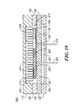
- FIG. 19 a cross section of a final state of the actuation sequence of liquid metal reflective optical switch 105 is shown, according to certain embodiments of the present invention.
- slug 225 has moved from the first side to the second side of chamber 230 .
- the slug 225 is wetted by liquid metal 215 so that a signal of first optical waveguide 150 is reflected by a reflective coating due to liquid metal 215 .
- the signal of first optical waveguide 150 is operable to be coupled to a second optical waveguide of second plurality of optical waveguides 205 after being reflected by the reflective coating.
- FIGS. 10-18 other sequences of actuation, such as actuating every other piezoelectric element of plurality of piezoelectric elements 235 , could be used without departing from the spirit and scope of the present invention.
- the liquid metal reflective optical switch 105 operates by means of the lateral displacement of one or more of the plurality of piezoelectric elements 235 in an extension mode thereby displacing slug 225 that is wetted by a liquid metal 215 and causing the liquid metal 215 to wet a portion of the plurality of wetting pads 220 .
- the wetting of the plurality of wetting pads 220 in conjunction with plurality of ridges 222 creates a reflective surface operable to route a signal of a third optical waveguide of first plurality of optical waveguides 150 to a fourth optical waveguide of second plurality of optical waveguides 160 .
- the liquid metal reflective optical switch 105 latches by means of a surface tension due to the liquid metal 215 wetting slug 225 to the plurality of wetting pads 220 .
Landscapes
- Physics & Mathematics (AREA)
- General Physics & Mathematics (AREA)
- Optics & Photonics (AREA)
- Mechanical Light Control Or Optical Switches (AREA)
Abstract
Description
Claims (37)
Priority Applications (3)
| Application Number | Priority Date | Filing Date | Title |
|---|---|---|---|
| US10/412,910 US6765161B1 (en) | 2003-04-14 | 2003-04-14 | Method and structure for a slug caterpillar piezoelectric latching reflective optical relay |
| PCT/US2004/002708 WO2004109372A2 (en) | 2003-04-14 | 2004-01-30 | Slug caterpillar piezoelectric latching reflective optical relay |
| EP04707035A EP1652204B1 (en) | 2003-04-14 | 2004-01-30 | Method and structure for a slug caterpillar piezoelectric latching reflective optical relay |
Applications Claiming Priority (1)
| Application Number | Priority Date | Filing Date | Title |
|---|---|---|---|
| US10/412,910 US6765161B1 (en) | 2003-04-14 | 2003-04-14 | Method and structure for a slug caterpillar piezoelectric latching reflective optical relay |
Publications (1)
| Publication Number | Publication Date |
|---|---|
| US6765161B1 true US6765161B1 (en) | 2004-07-20 |
Family
ID=32681874
Family Applications (1)
| Application Number | Title | Priority Date | Filing Date |
|---|---|---|---|
| US10/412,910 Expired - Fee Related US6765161B1 (en) | 2003-04-14 | 2003-04-14 | Method and structure for a slug caterpillar piezoelectric latching reflective optical relay |
Country Status (3)
| Country | Link |
|---|---|
| US (1) | US6765161B1 (en) |
| EP (1) | EP1652204B1 (en) |
| WO (1) | WO2004109372A2 (en) |
Cited By (8)
| Publication number | Priority date | Publication date | Assignee | Title |
|---|---|---|---|---|
| US20040159533A1 (en) * | 2002-08-13 | 2004-08-19 | You Kondoh | Liquid metal micro-relay with suspended heaters and multilayer wiring |
| US20040201310A1 (en) * | 2003-04-14 | 2004-10-14 | Wong Marvin Glenn | Damped longitudinal mode optical latching relay |
| US20040201312A1 (en) * | 2003-04-14 | 2004-10-14 | Arthur Fong | Method and structure for a slug assisted longitudinal piezoelectrically actuated liquid metal optical switch |
| US20040201329A1 (en) * | 2003-04-14 | 2004-10-14 | Wong Marvin Glenn | Damped longitudinal mode latching relay |
| US20040201316A1 (en) * | 2003-04-14 | 2004-10-14 | Arthur Fong | Method and structure for a solid slug caterpillar piezoelectric relay |
| US20050018956A1 (en) * | 2003-07-23 | 2005-01-27 | Tyler Sims | Clean and test for fluid within a reflection optical switch system |
| US20060108209A1 (en) * | 2004-11-24 | 2006-05-25 | Timothy Beerling | Liquid metal switch employing electrowetting for actuation and architectures for implementing same |
| US20060246843A1 (en) * | 2002-12-20 | 2006-11-02 | Taavi Hirvonen | Method and arrangement for testing a radio device |
Citations (82)
| Publication number | Priority date | Publication date | Assignee | Title |
|---|---|---|---|---|
| US2312672A (en) | 1941-05-09 | 1943-03-02 | Bell Telephone Labor Inc | Switching device |
| US2564081A (en) | 1946-05-23 | 1951-08-14 | Babson Bros Co | Mercury switch |
| US3430020A (en) | 1965-08-20 | 1969-02-25 | Siemens Ag | Piezoelectric relay |
| US3529268A (en) | 1967-12-04 | 1970-09-15 | Siemens Ag | Position-independent mercury relay |
| US3600537A (en) | 1969-04-15 | 1971-08-17 | Mechanical Enterprises Inc | Switch |
| US3639165A (en) | 1968-06-20 | 1972-02-01 | Gen Electric | Resistor thin films formed by low-pressure deposition of molybdenum and tungsten |
| US3657647A (en) | 1970-02-10 | 1972-04-18 | Curtis Instr | Variable bore mercury microcoulometer |
| US4103135A (en) | 1976-07-01 | 1978-07-25 | International Business Machines Corporation | Gas operated switches |
| US4158118A (en) * | 1974-08-30 | 1979-06-12 | Graf Ronald E | Electrostatic switch |
| FR2418539A1 (en) | 1978-02-24 | 1979-09-21 | Orega Circuits & Commutation | Liquid contact relays driven by piezoelectric membrane - pref. of polyvinylidene fluoride film for high sensitivity at low power |
| US4200779A (en) | 1977-09-06 | 1980-04-29 | Moscovsky Inzhenerno-Fizichesky Institut | Device for switching electrical circuits |
| US4238748A (en) | 1977-05-27 | 1980-12-09 | Orega Circuits Et Commutation | Magnetically controlled switch with wetted contact |
| FR2458138A1 (en) | 1979-06-01 | 1980-12-26 | Socapex | RELAYS WITH WET CONTACTS AND PLANAR CIRCUIT COMPRISING SUCH A RELAY |
| US4245886A (en) | 1979-09-10 | 1981-01-20 | International Business Machines Corporation | Fiber optics light switch |
| US4336570A (en) | 1980-05-09 | 1982-06-22 | Gte Products Corporation | Radiation switch for photoflash unit |
| US4419650A (en) | 1979-08-23 | 1983-12-06 | Georgina Chrystall Hirtle | Liquid contact relay incorporating gas-containing finely reticular solid motor element for moving conductive liquid |
| US4434337A (en) | 1980-06-26 | 1984-02-28 | W. G/u/ nther GmbH | Mercury electrode switch |
| US4475033A (en) | 1982-03-08 | 1984-10-02 | Northern Telecom Limited | Positioning device for optical system element |
| US4505539A (en) | 1981-09-30 | 1985-03-19 | Siemens Aktiengesellschaft | Optical device or switch for controlling radiation conducted in an optical waveguide |
| US4582391A (en) | 1982-03-30 | 1986-04-15 | Socapex | Optical switch, and a matrix of such switches |
| US4628161A (en) | 1985-05-15 | 1986-12-09 | Thackrey James D | Distorted-pool mercury switch |
| US4652710A (en) | 1986-04-09 | 1987-03-24 | The United States Of America As Represented By The United States Department Of Energy | Mercury switch with non-wettable electrodes |
| US4657339A (en) | 1982-02-26 | 1987-04-14 | U.S. Philips Corporation | Fiber optic switch |
| US4742263A (en) | 1986-08-15 | 1988-05-03 | Pacific Bell | Piezoelectric switch |
| JPS63276838A (en) | 1987-05-06 | 1988-11-15 | Nec Corp | Conductive liquid contact relay |
| US4786130A (en) | 1985-05-29 | 1988-11-22 | The General Electric Company, P.L.C. | Fibre optic coupler |
| US4797519A (en) | 1987-04-17 | 1989-01-10 | Elenbaas George H | Mercury tilt switch and method of manufacture |
| US4804932A (en) | 1986-08-22 | 1989-02-14 | Nec Corporation | Mercury wetted contact switch |
| JPH01294317A (en) | 1988-05-20 | 1989-11-28 | Nec Corp | Conductive liquid contact switch |
| US4988157A (en) | 1990-03-08 | 1991-01-29 | Bell Communications Research, Inc. | Optical switch using bubbles |
| FR2667396A1 (en) | 1990-09-27 | 1992-04-03 | Inst Nat Sante Rech Med | Sensor for pressure measurement in a liquid medium |
| US5278012A (en) | 1989-03-29 | 1994-01-11 | Hitachi, Ltd. | Method for producing thin film multilayer substrate, and method and apparatus for detecting circuit conductor pattern of the substrate |
| EP0593836A1 (en) | 1992-10-22 | 1994-04-27 | International Business Machines Corporation | Near-field photon tunnelling devices |
| US5415026A (en) | 1992-02-27 | 1995-05-16 | Ford; David | Vibration warning device including mercury wetted reed gauge switches |
| US5502781A (en) | 1995-01-25 | 1996-03-26 | At&T Corp. | Integrated optical devices utilizing magnetostrictively, electrostrictively or photostrictively induced stress |
| JPH08125487A (en) | 1994-06-21 | 1996-05-17 | Kinseki Ltd | Piezoelectric vibrator |
| JPH09161640A (en) | 1995-12-13 | 1997-06-20 | Korea Electron Telecommun | Latching type thermal drive micro relay element |
| US5644676A (en) | 1994-06-23 | 1997-07-01 | Instrumentarium Oy | Thermal radiant source with filament encapsulated in protective film |
| US5675310A (en) | 1994-12-05 | 1997-10-07 | General Electric Company | Thin film resistors on organic surfaces |
| US5677823A (en) | 1993-05-06 | 1997-10-14 | Cavendish Kinetics Ltd. | Bi-stable memory element |
| US5751074A (en) | 1995-09-08 | 1998-05-12 | Edward B. Prior & Associates | Non-metallic liquid tilt switch and circuitry |
| US5751552A (en) | 1995-05-30 | 1998-05-12 | Motorola, Inc. | Semiconductor device balancing thermal expansion coefficient mismatch |
| US5828799A (en) | 1995-10-31 | 1998-10-27 | Hewlett-Packard Company | Thermal optical switches for light |
| US5841686A (en) | 1996-11-22 | 1998-11-24 | Ma Laboratories, Inc. | Dual-bank memory module with shared capacitors and R-C elements integrated into the module substrate |
| US5874770A (en) | 1996-10-10 | 1999-02-23 | General Electric Company | Flexible interconnect film including resistor and capacitor layers |
| US5875531A (en) | 1995-03-27 | 1999-03-02 | U.S. Philips Corporation | Method of manufacturing an electronic multilayer component |
| US5886407A (en) | 1993-04-14 | 1999-03-23 | Frank J. Polese | Heat-dissipating package for microcircuit devices |
| US5889325A (en) | 1996-07-25 | 1999-03-30 | Nec Corporation | Semiconductor device and method of manufacturing the same |
| US5912606A (en) | 1998-08-18 | 1999-06-15 | Northrop Grumman Corporation | Mercury wetted switch |
| US5915050A (en) | 1994-02-18 | 1999-06-22 | University Of Southampton | Optical device |
| WO1999046624A1 (en) | 1998-03-09 | 1999-09-16 | Bartels Mikrotechnik Gmbh | Optical switch and modular switch system consisting of optical switching elements |
| US5972737A (en) | 1993-04-14 | 1999-10-26 | Frank J. Polese | Heat-dissipating package for microcircuit devices and process for manufacture |
| US5994750A (en) | 1994-11-07 | 1999-11-30 | Canon Kabushiki Kaisha | Microstructure and method of forming the same |
| US6021048A (en) | 1998-02-17 | 2000-02-01 | Smith; Gary W. | High speed memory module |
| US6180873B1 (en) | 1997-10-02 | 2001-01-30 | Polaron Engineering Limited | Current conducting devices employing mesoscopically conductive liquids |
| US6201682B1 (en) | 1997-12-19 | 2001-03-13 | U.S. Philips Corporation | Thin-film component |
| US6207234B1 (en) | 1998-06-24 | 2001-03-27 | Vishay Vitramon Incorporated | Via formation for multilayer inductive devices and other devices |
| US6212308B1 (en) | 1998-08-03 | 2001-04-03 | Agilent Technologies Inc. | Thermal optical switches for light |
| US6225133B1 (en) | 1993-09-01 | 2001-05-01 | Nec Corporation | Method of manufacturing thin film capacitor |
| US6278541B1 (en) | 1997-01-10 | 2001-08-21 | Lasor Limited | System for modulating a beam of electromagnetic radiation |
| US6304450B1 (en) | 1999-07-15 | 2001-10-16 | Incep Technologies, Inc. | Inter-circuit encapsulated packaging |
| US6320994B1 (en) | 1999-12-22 | 2001-11-20 | Agilent Technolgies, Inc. | Total internal reflection optical switch |
| US6323447B1 (en) | 1998-12-30 | 2001-11-27 | Agilent Technologies, Inc. | Electrical contact breaker switch, integrated electrical contact breaker switch, and electrical contact switching method |
| US6351579B1 (en) | 1998-02-27 | 2002-02-26 | The Regents Of The University Of California | Optical fiber switch |
| US6356679B1 (en) | 2000-03-30 | 2002-03-12 | K2 Optronics, Inc. | Optical routing element for use in fiber optic systems |
| US20020037128A1 (en) | 2000-04-16 | 2002-03-28 | Burger Gerardus Johannes | Micro electromechanical system and method for transmissively switching optical signals |
| US6373356B1 (en) | 1999-05-21 | 2002-04-16 | Interscience, Inc. | Microelectromechanical liquid metal current carrying system, apparatus and method |
| US6396371B2 (en) | 2000-02-02 | 2002-05-28 | Raytheon Company | Microelectromechanical micro-relay with liquid metal contacts |
| US6396012B1 (en) | 1999-06-14 | 2002-05-28 | Rodger E. Bloomfield | Attitude sensing electrical switch |
| US6446317B1 (en) | 2000-03-31 | 2002-09-10 | Intel Corporation | Hybrid capacitor and method of fabrication therefor |
| US6453086B1 (en) | 1999-05-04 | 2002-09-17 | Corning Incorporated | Piezoelectric optical switch device |
| US20020146197A1 (en) | 2001-04-04 | 2002-10-10 | Yoon-Joong Yong | Light modulating system using deformable mirror arrays |
| US20020150323A1 (en) | 2001-01-09 | 2002-10-17 | Naoki Nishida | Optical switch |
| US6470106B2 (en) | 2001-01-05 | 2002-10-22 | Hewlett-Packard Company | Thermally induced pressure pulse operated bi-stable optical switch |
| US20020168133A1 (en) | 2001-05-09 | 2002-11-14 | Mitsubishi Denki Kabushiki Kaisha | Optical switch and optical waveguide apparatus |
| US6487333B2 (en) | 1999-12-22 | 2002-11-26 | Agilent Technologies, Inc. | Total internal reflection optical switch |
| US6512322B1 (en) | 2001-10-31 | 2003-01-28 | Agilent Technologies, Inc. | Longitudinal piezoelectric latching relay |
| US6515404B1 (en) | 2002-02-14 | 2003-02-04 | Agilent Technologies, Inc. | Bending piezoelectrically actuated liquid metal switch |
| US6516504B2 (en) | 1996-04-09 | 2003-02-11 | The Board Of Trustees Of The University Of Arkansas | Method of making capacitor with extremely wide band low impedance |
| US20030035611A1 (en) | 2001-08-15 | 2003-02-20 | Youchun Shi | Piezoelectric-optic switch and method of fabrication |
| US6559420B1 (en) | 2002-07-10 | 2003-05-06 | Agilent Technologies, Inc. | Micro-switch heater with varying gas sub-channel cross-section |
| US6633213B1 (en) | 2002-04-24 | 2003-10-14 | Agilent Technologies, Inc. | Double sided liquid metal micro switch |
Family Cites Families (2)
| Publication number | Priority date | Publication date | Assignee | Title |
|---|---|---|---|---|
| DE3147875A1 (en) * | 1981-12-03 | 1983-06-30 | Felten & Guilleaume Fernmeldeanlagen GmbH, 8500 Nürnberg | Optical switching device |
| US5208880A (en) * | 1992-04-30 | 1993-05-04 | General Electric Company | Microdynamical fiber-optic switch and method of switching using same |
-
2003
- 2003-04-14 US US10/412,910 patent/US6765161B1/en not_active Expired - Fee Related
-
2004
- 2004-01-30 WO PCT/US2004/002708 patent/WO2004109372A2/en active Application Filing
- 2004-01-30 EP EP04707035A patent/EP1652204B1/en not_active Expired - Lifetime
Patent Citations (85)
| Publication number | Priority date | Publication date | Assignee | Title |
|---|---|---|---|---|
| US2312672A (en) | 1941-05-09 | 1943-03-02 | Bell Telephone Labor Inc | Switching device |
| US2564081A (en) | 1946-05-23 | 1951-08-14 | Babson Bros Co | Mercury switch |
| US3430020A (en) | 1965-08-20 | 1969-02-25 | Siemens Ag | Piezoelectric relay |
| US3529268A (en) | 1967-12-04 | 1970-09-15 | Siemens Ag | Position-independent mercury relay |
| US3639165A (en) | 1968-06-20 | 1972-02-01 | Gen Electric | Resistor thin films formed by low-pressure deposition of molybdenum and tungsten |
| US3600537A (en) | 1969-04-15 | 1971-08-17 | Mechanical Enterprises Inc | Switch |
| US3657647A (en) | 1970-02-10 | 1972-04-18 | Curtis Instr | Variable bore mercury microcoulometer |
| US4158118A (en) * | 1974-08-30 | 1979-06-12 | Graf Ronald E | Electrostatic switch |
| US4103135A (en) | 1976-07-01 | 1978-07-25 | International Business Machines Corporation | Gas operated switches |
| US4238748A (en) | 1977-05-27 | 1980-12-09 | Orega Circuits Et Commutation | Magnetically controlled switch with wetted contact |
| US4200779A (en) | 1977-09-06 | 1980-04-29 | Moscovsky Inzhenerno-Fizichesky Institut | Device for switching electrical circuits |
| FR2418539A1 (en) | 1978-02-24 | 1979-09-21 | Orega Circuits & Commutation | Liquid contact relays driven by piezoelectric membrane - pref. of polyvinylidene fluoride film for high sensitivity at low power |
| FR2458138A1 (en) | 1979-06-01 | 1980-12-26 | Socapex | RELAYS WITH WET CONTACTS AND PLANAR CIRCUIT COMPRISING SUCH A RELAY |
| US4419650A (en) | 1979-08-23 | 1983-12-06 | Georgina Chrystall Hirtle | Liquid contact relay incorporating gas-containing finely reticular solid motor element for moving conductive liquid |
| US4245886A (en) | 1979-09-10 | 1981-01-20 | International Business Machines Corporation | Fiber optics light switch |
| US4336570A (en) | 1980-05-09 | 1982-06-22 | Gte Products Corporation | Radiation switch for photoflash unit |
| US4434337A (en) | 1980-06-26 | 1984-02-28 | W. G/u/ nther GmbH | Mercury electrode switch |
| US4505539A (en) | 1981-09-30 | 1985-03-19 | Siemens Aktiengesellschaft | Optical device or switch for controlling radiation conducted in an optical waveguide |
| US4657339A (en) | 1982-02-26 | 1987-04-14 | U.S. Philips Corporation | Fiber optic switch |
| US4475033A (en) | 1982-03-08 | 1984-10-02 | Northern Telecom Limited | Positioning device for optical system element |
| US4582391A (en) | 1982-03-30 | 1986-04-15 | Socapex | Optical switch, and a matrix of such switches |
| US4628161A (en) | 1985-05-15 | 1986-12-09 | Thackrey James D | Distorted-pool mercury switch |
| US4786130A (en) | 1985-05-29 | 1988-11-22 | The General Electric Company, P.L.C. | Fibre optic coupler |
| US4652710A (en) | 1986-04-09 | 1987-03-24 | The United States Of America As Represented By The United States Department Of Energy | Mercury switch with non-wettable electrodes |
| US4742263A (en) | 1986-08-15 | 1988-05-03 | Pacific Bell | Piezoelectric switch |
| US4804932A (en) | 1986-08-22 | 1989-02-14 | Nec Corporation | Mercury wetted contact switch |
| US4797519A (en) | 1987-04-17 | 1989-01-10 | Elenbaas George H | Mercury tilt switch and method of manufacture |
| JPS63276838A (en) | 1987-05-06 | 1988-11-15 | Nec Corp | Conductive liquid contact relay |
| JPH01294317A (en) | 1988-05-20 | 1989-11-28 | Nec Corp | Conductive liquid contact switch |
| US5278012A (en) | 1989-03-29 | 1994-01-11 | Hitachi, Ltd. | Method for producing thin film multilayer substrate, and method and apparatus for detecting circuit conductor pattern of the substrate |
| US4988157A (en) | 1990-03-08 | 1991-01-29 | Bell Communications Research, Inc. | Optical switch using bubbles |
| FR2667396A1 (en) | 1990-09-27 | 1992-04-03 | Inst Nat Sante Rech Med | Sensor for pressure measurement in a liquid medium |
| US5415026A (en) | 1992-02-27 | 1995-05-16 | Ford; David | Vibration warning device including mercury wetted reed gauge switches |
| EP0593836A1 (en) | 1992-10-22 | 1994-04-27 | International Business Machines Corporation | Near-field photon tunnelling devices |
| US5886407A (en) | 1993-04-14 | 1999-03-23 | Frank J. Polese | Heat-dissipating package for microcircuit devices |
| US5972737A (en) | 1993-04-14 | 1999-10-26 | Frank J. Polese | Heat-dissipating package for microcircuit devices and process for manufacture |
| US5677823A (en) | 1993-05-06 | 1997-10-14 | Cavendish Kinetics Ltd. | Bi-stable memory element |
| US6225133B1 (en) | 1993-09-01 | 2001-05-01 | Nec Corporation | Method of manufacturing thin film capacitor |
| US5915050A (en) | 1994-02-18 | 1999-06-22 | University Of Southampton | Optical device |
| JPH08125487A (en) | 1994-06-21 | 1996-05-17 | Kinseki Ltd | Piezoelectric vibrator |
| US5644676A (en) | 1994-06-23 | 1997-07-01 | Instrumentarium Oy | Thermal radiant source with filament encapsulated in protective film |
| US5994750A (en) | 1994-11-07 | 1999-11-30 | Canon Kabushiki Kaisha | Microstructure and method of forming the same |
| US5849623A (en) | 1994-12-05 | 1998-12-15 | General Electric Company | Method of forming thin film resistors on organic surfaces |
| US5675310A (en) | 1994-12-05 | 1997-10-07 | General Electric Company | Thin film resistors on organic surfaces |
| US5502781A (en) | 1995-01-25 | 1996-03-26 | At&T Corp. | Integrated optical devices utilizing magnetostrictively, electrostrictively or photostrictively induced stress |
| US5875531A (en) | 1995-03-27 | 1999-03-02 | U.S. Philips Corporation | Method of manufacturing an electronic multilayer component |
| US5751552A (en) | 1995-05-30 | 1998-05-12 | Motorola, Inc. | Semiconductor device balancing thermal expansion coefficient mismatch |
| US5751074A (en) | 1995-09-08 | 1998-05-12 | Edward B. Prior & Associates | Non-metallic liquid tilt switch and circuitry |
| US5828799A (en) | 1995-10-31 | 1998-10-27 | Hewlett-Packard Company | Thermal optical switches for light |
| JPH09161640A (en) | 1995-12-13 | 1997-06-20 | Korea Electron Telecommun | Latching type thermal drive micro relay element |
| US6516504B2 (en) | 1996-04-09 | 2003-02-11 | The Board Of Trustees Of The University Of Arkansas | Method of making capacitor with extremely wide band low impedance |
| US5889325A (en) | 1996-07-25 | 1999-03-30 | Nec Corporation | Semiconductor device and method of manufacturing the same |
| US5874770A (en) | 1996-10-10 | 1999-02-23 | General Electric Company | Flexible interconnect film including resistor and capacitor layers |
| US5841686A (en) | 1996-11-22 | 1998-11-24 | Ma Laboratories, Inc. | Dual-bank memory module with shared capacitors and R-C elements integrated into the module substrate |
| US6278541B1 (en) | 1997-01-10 | 2001-08-21 | Lasor Limited | System for modulating a beam of electromagnetic radiation |
| US6180873B1 (en) | 1997-10-02 | 2001-01-30 | Polaron Engineering Limited | Current conducting devices employing mesoscopically conductive liquids |
| US6201682B1 (en) | 1997-12-19 | 2001-03-13 | U.S. Philips Corporation | Thin-film component |
| US6021048A (en) | 1998-02-17 | 2000-02-01 | Smith; Gary W. | High speed memory module |
| US6351579B1 (en) | 1998-02-27 | 2002-02-26 | The Regents Of The University Of California | Optical fiber switch |
| WO1999046624A1 (en) | 1998-03-09 | 1999-09-16 | Bartels Mikrotechnik Gmbh | Optical switch and modular switch system consisting of optical switching elements |
| US6408112B1 (en) | 1998-03-09 | 2002-06-18 | Bartels Mikrotechnik Gmbh | Optical switch and modular switching system comprising of optical switching elements |
| US6207234B1 (en) | 1998-06-24 | 2001-03-27 | Vishay Vitramon Incorporated | Via formation for multilayer inductive devices and other devices |
| US6212308B1 (en) | 1998-08-03 | 2001-04-03 | Agilent Technologies Inc. | Thermal optical switches for light |
| US5912606A (en) | 1998-08-18 | 1999-06-15 | Northrop Grumman Corporation | Mercury wetted switch |
| US6323447B1 (en) | 1998-12-30 | 2001-11-27 | Agilent Technologies, Inc. | Electrical contact breaker switch, integrated electrical contact breaker switch, and electrical contact switching method |
| US6453086B1 (en) | 1999-05-04 | 2002-09-17 | Corning Incorporated | Piezoelectric optical switch device |
| US6373356B1 (en) | 1999-05-21 | 2002-04-16 | Interscience, Inc. | Microelectromechanical liquid metal current carrying system, apparatus and method |
| US6501354B1 (en) | 1999-05-21 | 2002-12-31 | Interscience, Inc. | Microelectromechanical liquid metal current carrying system, apparatus and method |
| US6396012B1 (en) | 1999-06-14 | 2002-05-28 | Rodger E. Bloomfield | Attitude sensing electrical switch |
| US6304450B1 (en) | 1999-07-15 | 2001-10-16 | Incep Technologies, Inc. | Inter-circuit encapsulated packaging |
| US6487333B2 (en) | 1999-12-22 | 2002-11-26 | Agilent Technologies, Inc. | Total internal reflection optical switch |
| US6320994B1 (en) | 1999-12-22 | 2001-11-20 | Agilent Technolgies, Inc. | Total internal reflection optical switch |
| US6396371B2 (en) | 2000-02-02 | 2002-05-28 | Raytheon Company | Microelectromechanical micro-relay with liquid metal contacts |
| US6356679B1 (en) | 2000-03-30 | 2002-03-12 | K2 Optronics, Inc. | Optical routing element for use in fiber optic systems |
| US6446317B1 (en) | 2000-03-31 | 2002-09-10 | Intel Corporation | Hybrid capacitor and method of fabrication therefor |
| US20020037128A1 (en) | 2000-04-16 | 2002-03-28 | Burger Gerardus Johannes | Micro electromechanical system and method for transmissively switching optical signals |
| US6470106B2 (en) | 2001-01-05 | 2002-10-22 | Hewlett-Packard Company | Thermally induced pressure pulse operated bi-stable optical switch |
| US20020150323A1 (en) | 2001-01-09 | 2002-10-17 | Naoki Nishida | Optical switch |
| US20020146197A1 (en) | 2001-04-04 | 2002-10-10 | Yoon-Joong Yong | Light modulating system using deformable mirror arrays |
| US20020168133A1 (en) | 2001-05-09 | 2002-11-14 | Mitsubishi Denki Kabushiki Kaisha | Optical switch and optical waveguide apparatus |
| US20030035611A1 (en) | 2001-08-15 | 2003-02-20 | Youchun Shi | Piezoelectric-optic switch and method of fabrication |
| US6512322B1 (en) | 2001-10-31 | 2003-01-28 | Agilent Technologies, Inc. | Longitudinal piezoelectric latching relay |
| US6515404B1 (en) | 2002-02-14 | 2003-02-04 | Agilent Technologies, Inc. | Bending piezoelectrically actuated liquid metal switch |
| US6633213B1 (en) | 2002-04-24 | 2003-10-14 | Agilent Technologies, Inc. | Double sided liquid metal micro switch |
| US6559420B1 (en) | 2002-07-10 | 2003-05-06 | Agilent Technologies, Inc. | Micro-switch heater with varying gas sub-channel cross-section |
Non-Patent Citations (5)
| Title |
|---|
| "Integral Power Resistors for Aluminum Substrate." IBM Technical Disclosure Bulletin, Jun. 1984, US, Jun. 1, 1984, p. 827, vol. 27, No. 1B, TDB-ACC-NO: NB8406827, Cross Reference: 0018-8689-27-1B-827. |
| Bhedwar, Homi C. et al. "Ceramic Multilayer Package Fabrication." Electronic Materials Handbook, Nov. 1989, pp. 460-469, vol. 1 Packaging, Section 4: Packages. |
| Jonathan Simon, "A Liquid-Filled Microrelay with a Moving Mercury Microdrop" (Sep. 1997) Journal of Microelectromechanical Systems, vol. 6, No. 3, pp. 208-216. |
| Kim, Joonwon et al. "A Micromechanical Switch with Electrostatically Driven Liquid-Metal Droplet." Sensors and Actuators, A: Physical. v 9798, Apr. 1, 2002, 4 pages. |
| Marvin Glenn Wong, "A Piezoelectrically Actuated Liquid Metal Switch", May 1, 2002, Patent Application 10/137,691, 12 pages of specification, 5 pages of claims, 1 page of abstract, and 10 sheets of drawings (Figs. 1-10). |
Cited By (18)
| Publication number | Priority date | Publication date | Assignee | Title |
|---|---|---|---|---|
| US6806431B2 (en) * | 2002-08-13 | 2004-10-19 | Agilent Technologies, Inc. | Liquid metal micro-relay with suspended heaters and multilayer wiring |
| US20040159533A1 (en) * | 2002-08-13 | 2004-08-19 | You Kondoh | Liquid metal micro-relay with suspended heaters and multilayer wiring |
| US7680463B2 (en) * | 2002-12-20 | 2010-03-16 | Jot Automation Oy | Method and arrangement for testing a radio device |
| US20060246843A1 (en) * | 2002-12-20 | 2006-11-02 | Taavi Hirvonen | Method and arrangement for testing a radio device |
| US6876130B2 (en) * | 2003-04-14 | 2005-04-05 | Agilent Technologies, Inc. | Damped longitudinal mode latching relay |
| US6876132B2 (en) * | 2003-04-14 | 2005-04-05 | Agilent Technologies, Inc. | Method and structure for a solid slug caterpillar piezoelectric relay |
| US20040201329A1 (en) * | 2003-04-14 | 2004-10-14 | Wong Marvin Glenn | Damped longitudinal mode latching relay |
| US6879089B2 (en) * | 2003-04-14 | 2005-04-12 | Agilent Technologies, Inc. | Damped longitudinal mode optical latching relay |
| US6946775B2 (en) * | 2003-04-14 | 2005-09-20 | Agilent Technologies, Inc. | Method and structure for a slug assisted longitudinal piezoelectrically actuated liquid metal optical switch |
| US20040201316A1 (en) * | 2003-04-14 | 2004-10-14 | Arthur Fong | Method and structure for a solid slug caterpillar piezoelectric relay |
| US20040201310A1 (en) * | 2003-04-14 | 2004-10-14 | Wong Marvin Glenn | Damped longitudinal mode optical latching relay |
| US20040201312A1 (en) * | 2003-04-14 | 2004-10-14 | Arthur Fong | Method and structure for a slug assisted longitudinal piezoelectrically actuated liquid metal optical switch |
| US7274840B2 (en) * | 2003-07-23 | 2007-09-25 | Avago Technologies Fiber Ip (Singapore) Pte. Ltd. | Clean and test for fluid within a reflection optical switch system |
| US20050018956A1 (en) * | 2003-07-23 | 2005-01-27 | Tyler Sims | Clean and test for fluid within a reflection optical switch system |
| US20060108209A1 (en) * | 2004-11-24 | 2006-05-25 | Timothy Beerling | Liquid metal switch employing electrowetting for actuation and architectures for implementing same |
| US7268310B2 (en) * | 2004-11-24 | 2007-09-11 | Agilent Technologies, Inc. | Liquid metal switch employing electrowetting for actuation and architectures for implementing same |
| US7132614B2 (en) * | 2004-11-24 | 2006-11-07 | Agilent Technologies, Inc. | Liquid metal switch employing electrowetting for actuation and architectures for implementing same |
| US20060201795A1 (en) * | 2004-11-24 | 2006-09-14 | Timothy Beerling | Liquid metal switch employing electrowetting for actuation and architectures for implementing same |
Also Published As
| Publication number | Publication date |
|---|---|
| WO2004109372A2 (en) | 2004-12-16 |
| WO2004109372A3 (en) | 2005-03-17 |
| EP1652204A2 (en) | 2006-05-03 |
| EP1652204A4 (en) | 2008-03-05 |
| EP1652204B1 (en) | 2013-03-13 |
Similar Documents
| Publication | Publication Date | Title |
|---|---|---|
| US6360033B1 (en) | Optical switch incorporating therein shallow arch leaf springs | |
| US6765161B1 (en) | Method and structure for a slug caterpillar piezoelectric latching reflective optical relay | |
| US6768068B1 (en) | Method and structure for a slug pusher-mode piezoelectrically actuated liquid metal switch | |
| US6903492B2 (en) | Wetting finger latching piezoelectric relay | |
| US7012354B2 (en) | Method and structure for a pusher-mode piezoelectrically actuated liquid metal switch | |
| US6730866B1 (en) | High-frequency, liquid metal, latching relay array | |
| US6891315B2 (en) | Shear mode liquid metal switch | |
| US6818844B2 (en) | Method and structure for a slug assisted pusher-mode piezoelectrically actuated liquid metal optical switch | |
| US6816641B2 (en) | Method and structure for a solid slug caterpillar piezoelectric optical relay | |
| US6876132B2 (en) | Method and structure for a solid slug caterpillar piezoelectric relay | |
| US6956990B2 (en) | Reflecting wedge optical wavelength multiplexer/demultiplexer | |
| US6925223B2 (en) | Pressure actuated optical latching relay | |
| US6946775B2 (en) | Method and structure for a slug assisted longitudinal piezoelectrically actuated liquid metal optical switch | |
| US20040201906A1 (en) | Longitudinal mode solid slug optical latching relay | |
| US6870111B2 (en) | Bending mode liquid metal switch | |
| US6961487B2 (en) | Method and structure for a pusher-mode piezoelectrically actuated liquid metal optical switch | |
| US6798937B1 (en) | Pressure actuated solid slug optical latching relay | |
| US6903490B2 (en) | Longitudinal mode optical latching relay | |
| US6920259B2 (en) | Longitudinal electromagnetic latching optical relay | |
| US20040201320A1 (en) | Inserting-finger liquid metal relay |
Legal Events
| Date | Code | Title | Description |
|---|---|---|---|
| AS | Assignment |
Owner name: AGILENT TECHNOLOGIES, INC., COLORADO Free format text: ASSIGNMENT OF ASSIGNORS INTEREST;ASSIGNORS:WONG, MARVIN GLENN;FONG, ARTHUR;REEL/FRAME:013836/0027 Effective date: 20030408 |
|
| AS | Assignment |
Owner name: AVAGO TECHNOLOGIES GENERAL IP PTE. LTD., SINGAPORE Free format text: ASSIGNMENT OF ASSIGNORS INTEREST;ASSIGNOR:AGILENT TECHNOLOGIES, INC.;REEL/FRAME:017207/0020 Effective date: 20051201 |
|
| AS | Assignment |
Owner name: AVAGO TECHNOLOGIES ECBU IP (SINGAPORE) PTE. LTD.,S Free format text: ASSIGNMENT OF ASSIGNORS INTEREST;ASSIGNOR:AVAGO TECHNOLOGIES GENERAL IP (SINGAPORE) PTE. LTD.;REEL/FRAME:017675/0518 Effective date: 20060127 Owner name: AVAGO TECHNOLOGIES ECBU IP (SINGAPORE) PTE. LTD., Free format text: ASSIGNMENT OF ASSIGNORS INTEREST;ASSIGNOR:AVAGO TECHNOLOGIES GENERAL IP (SINGAPORE) PTE. LTD.;REEL/FRAME:017675/0518 Effective date: 20060127 |
|
| FPAY | Fee payment |
Year of fee payment: 4 |
|
| REMI | Maintenance fee reminder mailed | ||
| FPAY | Fee payment |
Year of fee payment: 8 |
|
| AS | Assignment |
Owner name: AVAGO TECHNOLOGIES GENERAL IP (SINGAPORE) PTE. LTD Free format text: MERGER;ASSIGNOR:AVAGO TECHNOLOGIES ECBU IP (SINGAPORE) PTE. LTD.;REEL/FRAME:030369/0528 Effective date: 20121030 |
|
| REMI | Maintenance fee reminder mailed | ||
| AS | Assignment |
Owner name: AVAGO TECHNOLOGIES GENERAL IP (SINGAPORE) PTE. LTD Free format text: CORRECTIVE ASSIGNMENT TO CORRECT THE NAME OF THE ASSIGNEE PREVIOUSLY RECORDED ON REEL 017207 FRAME 0020. ASSIGNOR(S) HEREBY CONFIRMS THE ASSIGNMENT;ASSIGNOR:AGILENT TECHNOLOGIES, INC.;REEL/FRAME:038633/0001 Effective date: 20051201 |
|
| LAPS | Lapse for failure to pay maintenance fees | ||
| STCH | Information on status: patent discontinuation |
Free format text: PATENT EXPIRED DUE TO NONPAYMENT OF MAINTENANCE FEES UNDER 37 CFR 1.362 |
|
| FP | Lapsed due to failure to pay maintenance fee |
Effective date: 20160720 |