US6163559A - Beam expander for ultraviolet lasers - Google Patents
Beam expander for ultraviolet lasers Download PDFInfo
- Publication number
- US6163559A US6163559A US09/102,241 US10224198A US6163559A US 6163559 A US6163559 A US 6163559A US 10224198 A US10224198 A US 10224198A US 6163559 A US6163559 A US 6163559A
- Authority
- US
- United States
- Prior art keywords
- laser
- mirror
- grating
- cylindrical
- mirrors
- Prior art date
- Legal status (The legal status is an assumption and is not a legal conclusion. Google has not performed a legal analysis and makes no representation as to the accuracy of the status listed.)
- Expired - Lifetime
Links
- 238000007906 compression Methods 0.000 claims description 6
- 230000006835 compression Effects 0.000 claims description 5
- YCKRFDGAMUMZLT-UHFFFAOYSA-N Fluorine atom Chemical compound [F] YCKRFDGAMUMZLT-UHFFFAOYSA-N 0.000 claims 3
- 229910052731 fluorine Inorganic materials 0.000 claims 3
- 239000011737 fluorine Substances 0.000 claims 3
- XKRFYHLGVUSROY-UHFFFAOYSA-N Argon Chemical compound [Ar] XKRFYHLGVUSROY-UHFFFAOYSA-N 0.000 claims 2
- 239000007789 gas Substances 0.000 claims 2
- 229910052786 argon Inorganic materials 0.000 claims 1
- 229910052743 krypton Inorganic materials 0.000 claims 1
- DNNSSWSSYDEUBZ-UHFFFAOYSA-N krypton atom Chemical compound [Kr] DNNSSWSSYDEUBZ-UHFFFAOYSA-N 0.000 claims 1
- 230000003287 optical effect Effects 0.000 description 22
- 238000000034 method Methods 0.000 description 5
- 238000004519 manufacturing process Methods 0.000 description 4
- 239000000463 material Substances 0.000 description 4
- 230000003595 spectral effect Effects 0.000 description 4
- ISQINHMJILFLAQ-UHFFFAOYSA-N argon hydrofluoride Chemical compound F.[Ar] ISQINHMJILFLAQ-UHFFFAOYSA-N 0.000 description 3
- 238000005259 measurement Methods 0.000 description 3
- 238000010521 absorption reaction Methods 0.000 description 2
- 238000013461 design Methods 0.000 description 2
- 238000001459 lithography Methods 0.000 description 2
- 238000001228 spectrum Methods 0.000 description 2
- 230000003321 amplification Effects 0.000 description 1
- 238000010420 art technique Methods 0.000 description 1
- 239000011248 coating agent Substances 0.000 description 1
- 238000000576 coating method Methods 0.000 description 1
- 238000011161 development Methods 0.000 description 1
- 239000011521 glass Substances 0.000 description 1
- 238000010438 heat treatment Methods 0.000 description 1
- 238000007567 mass-production technique Methods 0.000 description 1
- 238000003199 nucleic acid amplification method Methods 0.000 description 1
- 238000007517 polishing process Methods 0.000 description 1
- 238000011160 research Methods 0.000 description 1
- 238000003892 spreading Methods 0.000 description 1
- 238000011144 upstream manufacturing Methods 0.000 description 1
Images


Classifications
-
- G—PHYSICS
- G03—PHOTOGRAPHY; CINEMATOGRAPHY; ANALOGOUS TECHNIQUES USING WAVES OTHER THAN OPTICAL WAVES; ELECTROGRAPHY; HOLOGRAPHY
- G03F—PHOTOMECHANICAL PRODUCTION OF TEXTURED OR PATTERNED SURFACES, e.g. FOR PRINTING, FOR PROCESSING OF SEMICONDUCTOR DEVICES; MATERIALS THEREFOR; ORIGINALS THEREFOR; APPARATUS SPECIALLY ADAPTED THEREFOR
- G03F7/00—Photomechanical, e.g. photolithographic, production of textured or patterned surfaces, e.g. printing surfaces; Materials therefor, e.g. comprising photoresists; Apparatus specially adapted therefor
- G03F7/70—Microphotolithographic exposure; Apparatus therefor
- G03F7/70483—Information management; Active and passive control; Testing; Wafer monitoring, e.g. pattern monitoring
- G03F7/7055—Exposure light control in all parts of the microlithographic apparatus, e.g. pulse length control or light interruption
- G03F7/70575—Wavelength control, e.g. control of bandwidth, multiple wavelength, selection of wavelength or matching of optical components to wavelength
-
- G—PHYSICS
- G02—OPTICS
- G02B—OPTICAL ELEMENTS, SYSTEMS OR APPARATUS
- G02B19/00—Condensers, e.g. light collectors or similar non-imaging optics
- G02B19/0004—Condensers, e.g. light collectors or similar non-imaging optics characterised by the optical means employed
- G02B19/0019—Condensers, e.g. light collectors or similar non-imaging optics characterised by the optical means employed having reflective surfaces only (e.g. louvre systems, systems with multiple planar reflectors)
- G02B19/0023—Condensers, e.g. light collectors or similar non-imaging optics characterised by the optical means employed having reflective surfaces only (e.g. louvre systems, systems with multiple planar reflectors) at least one surface having optical power
-
- G—PHYSICS
- G02—OPTICS
- G02B—OPTICAL ELEMENTS, SYSTEMS OR APPARATUS
- G02B19/00—Condensers, e.g. light collectors or similar non-imaging optics
- G02B19/0033—Condensers, e.g. light collectors or similar non-imaging optics characterised by the use
-
- G—PHYSICS
- G02—OPTICS
- G02B—OPTICAL ELEMENTS, SYSTEMS OR APPARATUS
- G02B19/00—Condensers, e.g. light collectors or similar non-imaging optics
- G02B19/0033—Condensers, e.g. light collectors or similar non-imaging optics characterised by the use
- G02B19/0095—Condensers, e.g. light collectors or similar non-imaging optics characterised by the use for use with ultraviolet radiation
-
- G—PHYSICS
- G02—OPTICS
- G02B—OPTICAL ELEMENTS, SYSTEMS OR APPARATUS
- G02B26/00—Optical devices or arrangements for the control of light using movable or deformable optical elements
- G02B26/06—Optical devices or arrangements for the control of light using movable or deformable optical elements for controlling the phase of light
-
- G—PHYSICS
- G02—OPTICS
- G02B—OPTICAL ELEMENTS, SYSTEMS OR APPARATUS
- G02B26/00—Optical devices or arrangements for the control of light using movable or deformable optical elements
- G02B26/08—Optical devices or arrangements for the control of light using movable or deformable optical elements for controlling the direction of light
- G02B26/0816—Optical devices or arrangements for the control of light using movable or deformable optical elements for controlling the direction of light by means of one or more reflecting elements
- G02B26/0825—Optical devices or arrangements for the control of light using movable or deformable optical elements for controlling the direction of light by means of one or more reflecting elements the reflecting element being a flexible sheet or membrane, e.g. for varying the focus
-
- G—PHYSICS
- G02—OPTICS
- G02B—OPTICAL ELEMENTS, SYSTEMS OR APPARATUS
- G02B27/00—Optical systems or apparatus not provided for by any of the groups G02B1/00 - G02B26/00, G02B30/00
- G02B27/0081—Optical systems or apparatus not provided for by any of the groups G02B1/00 - G02B26/00, G02B30/00 with means for altering, e.g. enlarging, the entrance or exit pupil
-
- G—PHYSICS
- G02—OPTICS
- G02B—OPTICAL ELEMENTS, SYSTEMS OR APPARATUS
- G02B5/00—Optical elements other than lenses
- G02B5/18—Diffraction gratings
- G02B5/1828—Diffraction gratings having means for producing variable diffraction
-
- H—ELECTRICITY
- H01—ELECTRIC ELEMENTS
- H01S—DEVICES USING THE PROCESS OF LIGHT AMPLIFICATION BY STIMULATED EMISSION OF RADIATION [LASER] TO AMPLIFY OR GENERATE LIGHT; DEVICES USING STIMULATED EMISSION OF ELECTROMAGNETIC RADIATION IN WAVE RANGES OTHER THAN OPTICAL
- H01S3/00—Lasers, i.e. devices using stimulated emission of electromagnetic radiation in the infrared, visible or ultraviolet wave range
- H01S3/05—Construction or shape of optical resonators; Accommodation of active medium therein; Shape of active medium
- H01S3/08—Construction or shape of optical resonators or components thereof
- H01S3/08004—Construction or shape of optical resonators or components thereof incorporating a dispersive element, e.g. a prism for wavelength selection
- H01S3/08009—Construction or shape of optical resonators or components thereof incorporating a dispersive element, e.g. a prism for wavelength selection using a diffraction grating
-
- H—ELECTRICITY
- H01—ELECTRIC ELEMENTS
- H01S—DEVICES USING THE PROCESS OF LIGHT AMPLIFICATION BY STIMULATED EMISSION OF RADIATION [LASER] TO AMPLIFY OR GENERATE LIGHT; DEVICES USING STIMULATED EMISSION OF ELECTROMAGNETIC RADIATION IN WAVE RANGES OTHER THAN OPTICAL
- H01S3/00—Lasers, i.e. devices using stimulated emission of electromagnetic radiation in the infrared, visible or ultraviolet wave range
- H01S3/14—Lasers, i.e. devices using stimulated emission of electromagnetic radiation in the infrared, visible or ultraviolet wave range characterised by the material used as the active medium
- H01S3/22—Gases
- H01S3/223—Gases the active gas being polyatomic, i.e. containing two or more atoms
- H01S3/225—Gases the active gas being polyatomic, i.e. containing two or more atoms comprising an excimer or exciplex
Definitions
- This invention relates to laser beam expanders and in particular such beam expanders used for line narrowing ultraviolet lasers.
- the natural band width of many ultraviolet lasers is relatively wide.
- the spectral width of an argon fluoride excimer laser is approximately 500 pm (FWHM).
- One of the important uses of the ArF laser is for integrated circuit lithography in which case the beam is preferably line narrowed such that 95 percent of the beam energy is spread over a spectrum only about 1 pm.
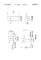
- Known method for expanding (and shrinking) the beam in a single direction include the use of one or more prisms as shown in FIG. 1A and at least two cylindrical lenses as shown in FIG. 1B.
- Lenses and prisms work well as beam expanders for visible light and relatively long wavelength ultraviolet beams. However, for short wavelength ultraviolet beams, very few materials are available which are sufficiently transparent to the light. When lenses or prisms not having perfect transparency are used to line narrow a high energy beam significant heating of the optic can occur, which can produce unwanted distortions of the optical properties of the beam. This problem is expected to become more severe as photolithographic laser requirements move toward shorter wavelengths and higher output powers.
- the present invention provides a line narrowed ultraviolet laser having a line narrowing system which includes a grating and an all reflective beam expander.
- the beam expander consists of a relatively small circular cylindrical mirror and relatively larger elliptical cylindrical mirror and the grating is an eclielle grating mounted in a Littrow configuration. Other mirror combinations are also disclosed.
- FIGS. 1A and 1B show prior art line narrowing configurations.
- FIG. 2 shows a first embodiment of the present invention.
- FIGS. 3A and 3B are two views of a circular cylindrical mirror.
- FIGS. 4A and 4B are two views of an almost circular, elliptical cylindrical mirror.
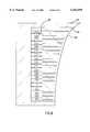
- FIG. 5 shows a second preferred embodiment of the present invention.
- FIG. 6 shows a method converting a circular cylindrical mirror for use in an embodiment of the present invention.
- FIGS. 7, 8, 9 and 10 show other preferred arrangements of cylindrical mirrors for beam expansion.
- FIG. 2 shows the principal optical element of a line narrowed argon fluoride excimer laser system 2.
- the system includes argon fluoride laser chamber 4. With Brewster or approximately Brewster windows 6 which produces excimer lasing between elongated electrodes (not shown) spaced vertically about 22 mm apart.
- the beam cross section of about 2.2 mm ⁇ 20 mm is defined by aperture 8.
- the beam is reflected first from convex circular cylindrical mirror 10 shown in detail in FIGS. 3A and 3B.
- Mirror 10 is 25 mm high having a convex surface S1 with cylindrical radius of 13.113 mm.
- the beam reflected from mirror 10 fans out toward elliptical cylindrical mirror 12 which is shown in detail in FIGS. 4A and 4B.
- the curved cylindrical surface S2 of mirror 12 is close to that of a cylindrical circular surface having a radius of 271.050 mm but is slightly more concave than a 271.050 mm cylindrical circular surface.
- the mirror is 58.00 mm wide.
- a first edge of the mirror is 8.00 mm from the optical axis of the mirror which is aligned with the optical axis of mirror 10 as shown in FIG. 2.
- a second edge of the mirror is located 66.00 mm from the optical axis of the mirror.
- Table I shows the sag of the curved surface at 14 equal spaced distances from the vertex.
- the table also shows the sag of the best fit cylindrical surface corresponding to the surface S2.
- the design of this optical arrangement was calculated using the well known Code 5 optical software available from Optical Research Associates with offices in Pasadena, Calif.
- the two mirrors are aligned as shown in FIG. 2 with a common optical axis 14.
- the edge of mirror 10 closest to the optical axis is 0.25 mm from the optical axis and the edge farthest away from the optical axis is 8.0 mm from the optical axis as shown in FIG. 3A.
- the edge of mirror 12 closest to the optical axis is 8 mm from the optical axis and the edge farthest from the optical axis is 66 mm from the optical axis as shown in FIG. 4A.
- the vertex of mirror 12 is located 127 mm from the vertex of mirror 10 as shown in FIG. 2.
- the laser chamber 4 and aperture 8 are arranged so that the center of the 2.2 mm wide laser beam 16 is aligned parallel to optical axis 14 and 4 mm from it so that the center of the beam is positioned approximately at the center of the curved surface of mirror 10.
- the rays of the beam from mirror 10 reflecting from mirror 12 will be directed in a direction parallel to beam 16 but the width of the expanded beam has been expanded from 2.2 mm about 21 times to about 46 mm.
- Echelle grating 18 which is arranged in a Littrow configuration has an active length of 250 mm and is positioned as shown in FIG. 2 to reflect from its active length the expanded beam from mirror 12.
- the grating is a prior art eschelle grating having 82 lines per ml and is designed to reflect a very narrow spectral band of light directly back on itself. Light outside this very narrow spectral band is reflected in different directions and nearly all of this out of band light does not pass back through aperture 8 so it does not thereafter contribute to the laser beam and is not amplified as is the light which does pass back through aperture 8.
- a portion of the beam such as 70 percent passes through output coupler 20 on each encounter with it and becomes a part of the output beam.
- FIG. 5 shows a preferred arrangement for controlling the wavelength and bandwidth of the laser.
- Eschelle grating 18 is pivotably mounted to pivot about pivot axle 22. The degree of pivot is controlled by motor drive 24 which in turn is controlled by feedback control processor 26 based on wavelength measurement signals from spectrographic instrument in wavelength and bandwidth measurement system 28.
- This system using any of several well known prior art techniques measures the wavelength and bandwidth of the output beam from a small portion of the beam reflected into the system from beam splitter 30.
- the bandwidth can be minimized by very slightly adjusting the curvature of the lined surface of grating 18 with a curvature adjusting mechanism 25 as shown in FIG. 5 by applying tension or compression forces on legs 32 as directed by feedback control processor 26 based on measurements from system 28.
- the controlled tension-compression can be provided by any one of many available linear drive units commercially available.
- mirror surfaces are preferably very tight. Surface accuracy should preferably be less than 1/20 of the wavelength of the laser beam. Mass production techniques are commercially available to produce surfaces as accurate as this. However, cylindrical aspheric surfaces such as mirror 12 are, more difficult to fabricate and are typically fabricated as a cylindrical mirror, then polished to the specified shape by precision and labor intensive hand polishing processes. However, automated production processes for these types of components are under development and expected to be available in the near future.
- Tilts in the plane of: beam expansion should be less than 50 ⁇ radians for the large mirror and the mirror positions should be accurate to 0.001 inch in order to keep wave front distortions to a small fraction of a wavelength.
- the mirror should preferably be fabricated from low expansion glass and coated with a coating appropriate for the wavelength of intended use.
- FIG. 6 discloses a technique for fabricating an elliptical cylindrical mirror such as that shown in FIGS. 2 and 5.
- a mirror material is machined into the general shape shown as 62 with a circular cylindrical surface 60 and is mounted in frame 64 with tension compression elements 66 mounted as shown.
- Surface 60 is then polished to a circular cylindrical surface to a very fine precision.
- tension compression elements are adjusted to deform surface 60 into the elliptical cylindrical surface shown in FIGS. 2 and 5 and Table I and the corresponding equation provided above.
- Element 66 could be adjustment bolts for adjustment by hand or they could be electronically controlled devices such as piezoelectric drivers.
- the present invention virtually eliminates distortion due to optical absorption of the laser beam. This is very important when dealing with high power UV light because good material for prisms and lenses are not available and even the best available optical materials have some absorption.
- the design shown in FIG. 2 is compact, has a relatively short optical path length comparable to prior prism based line narrowing systems.
- the system with careful fabrication and alignment can provide beam expansion with less than 0.07 waves of distortion (RMS value) at 193 nm. Distortions in this range would be considered "diffraction limited”.
- FIGS. 7, 8, 9 and 10 Many other all reflective beam expansion systems are possible for expanding ultraviolet laser beams which will be obvious to persons skilled in the art once they have read the foregoing. Four of these possible arrangements are shown in FIGS. 7, 8, 9 and 10. Many other beam cross sections may be chosen.
- the size of the aperture in the beam expansion direction is very important and should be chosen carefully recognizing the obvious trade off of beam energy vs. band width.
- the size of the aperture in the other direction is not nearly as critical.
- mirror 12 is a circular cylindrical mirror and grating 18 is deformed to correct for the wavefront distortion produced by the two mirrors.
- the grating could be deformed as shown in FIG. 5 or the curvature adjusting mechanism could be more elaborate such as shown in FIG. 6.
- the adjustment could be by hand using bolt type threaded devices or active electronic adjustment could be provided using an array of electronic drives which could be controlled in a feedback loop to adjust the curvature on a substantially real time basis.
- magnifications greater than the 21 ⁇ magnification of the first embodiment will require more precise control of surface accuracy. This will make fabrication of the optical devices more difficult.
- the present invention will be useful to narrow band ArF lasers at wavelengths of about 193 nm.
- the invention will also be useful to line narrow F 2 lasers operating at 157 nm if the F 2 lasers become commercially available for use in lithography.
Landscapes
- Physics & Mathematics (AREA)
- General Physics & Mathematics (AREA)
- Optics & Photonics (AREA)
- Electromagnetism (AREA)
- Engineering & Computer Science (AREA)
- Plasma & Fusion (AREA)
- Lasers (AREA)
Abstract
Description
              TABLE I
______________________________________
RADIUS OF BEST CYLINDER = 271.050
                      BEST FIT
Y        S1 SAG       CYL SAG  SAG DIFF.
______________________________________
 8.000000
         0.119804     0.118085  0.000000
12.640000
         0.299084     0.294884 -0.002481
17.280000
         0.558981     0.551379 -0.005883
21.920000
         0.899505     0.887797 -0.009989
26.560000
         1.320671     1.304438 -0.014514
31.200000
         1.822496     1.801672 -0.019105
35.840000
         2.405003     2.379949 -0.023334
40.480000
         3.068215     3.039793 -0.026702
45.120000
         3.812160     3.781807 -0.028633
49.760000
         4.636870     4.606679 -0.028472
54.400000
         5.542381     5.515180 -0.025482
59.040000
         6.528729     6.508172 -0.018838
63.680000
         7.595958     7.586611 -0.007629
66.000000
         8.159917     8.158198  0.000000
______________________________________
Claims (18)
Priority Applications (1)
| Application Number | Priority Date | Filing Date | Title |
|---|---|---|---|
| US09/102,241 US6163559A (en) | 1998-06-22 | 1998-06-22 | Beam expander for ultraviolet lasers |
Applications Claiming Priority (1)
| Application Number | Priority Date | Filing Date | Title |
|---|---|---|---|
| US09/102,241 US6163559A (en) | 1998-06-22 | 1998-06-22 | Beam expander for ultraviolet lasers |
Publications (1)
| Publication Number | Publication Date |
|---|---|
| US6163559A true US6163559A (en) | 2000-12-19 |
Family
ID=22288863
Family Applications (1)
| Application Number | Title | Priority Date | Filing Date |
|---|---|---|---|
| US09/102,241 Expired - Lifetime US6163559A (en) | 1998-06-22 | 1998-06-22 | Beam expander for ultraviolet lasers |
Country Status (1)
| Country | Link |
|---|---|
| US (1) | US6163559A (en) |
Cited By (24)
| Publication number | Priority date | Publication date | Assignee | Title |
|---|---|---|---|---|
| US6580517B2 (en) | 2000-03-01 | 2003-06-17 | Lambda Physik Ag | Absolute wavelength calibration of lithography laser using multiple element or tandem see through hollow cathode lamp |
| US6597462B2 (en) | 2000-03-01 | 2003-07-22 | Lambda Physik Ag | Laser wavelength and bandwidth monitor |
| US6603789B1 (en) | 2000-07-05 | 2003-08-05 | Lambda Physik Ag | Narrow band excimer or molecular fluorine laser with improved beam parameters |
| US6608848B2 (en) | 1998-06-01 | 2003-08-19 | Lambda Physik Ag | Method and apparatus for wavelength calibration |
| US6700915B2 (en) | 1999-03-12 | 2004-03-02 | Lambda Physik Ag | Narrow band excimer laser with a resonator containing an optical element for making wavefront corrections |
| US6747741B1 (en) | 2000-10-12 | 2004-06-08 | Lambda Physik Ag | Multiple-pass interferometric device |
| US6785316B1 (en) * | 1999-08-17 | 2004-08-31 | Lambda Physik Ag | Excimer or molecular laser with optimized spectral purity |
| US6801561B2 (en) | 2000-09-25 | 2004-10-05 | Lambda Physik Ag | Laser system and method for spectral narrowing through wavefront correction |
| US6807205B1 (en) | 2000-07-14 | 2004-10-19 | Lambda Physik Ag | Precise monitor etalon calibration technique |
| US6834066B2 (en) | 2000-04-18 | 2004-12-21 | Lambda Physik Ag | Stabilization technique for high repetition rate gas discharge lasers |
| US6834069B1 (en) * | 1999-12-15 | 2004-12-21 | Lambda Physik Ag | Molecular fluorine laser with intracavity polarization enhancer |
| US7006541B2 (en) | 1998-06-01 | 2006-02-28 | Lambda Physik Ag | Absolute wavelength calibration of lithography laser using multiple element or tandem see through hollow cathode lamp |
| US20060114958A1 (en) * | 2004-11-30 | 2006-06-01 | Cymer, Inc. | Method and apparatus for gas discharge laser bandwidth and center wavelength control |
| CN1299406C (en) * | 2001-03-02 | 2007-02-07 | 康宁股份有限公司 | High repetition rate excimer laser system |
| US20070098033A1 (en) * | 2005-11-01 | 2007-05-03 | Cymer, Inc. | External optics and chamber support system |
| US20080151944A1 (en) * | 2004-11-30 | 2008-06-26 | Cymer, Inc. | Line narrowing module |
| US20100149647A1 (en) * | 2008-10-24 | 2010-06-17 | Efrain Figueroa | System Method and Apparatus for Selecting and Controlling Light Source Bandwidth |
| DE102009020501A1 (en) * | 2009-05-08 | 2010-12-23 | Carl Zeiss Laser Optics Gmbh | Bandwidth narrowing module for adjusting a spectral bandwidth of a laser beam |
| US20110122900A1 (en) * | 2009-11-26 | 2011-05-26 | University Court Of The University Of St Andrews | Laser |
| US20110122901A1 (en) * | 2004-11-30 | 2011-05-26 | Cymer, Inc. | High power high pulse repetition rate gas discharge laser system |
| WO2012106971A1 (en) * | 2011-12-19 | 2012-08-16 | 华为技术有限公司 | External cavity laser |
| KR20120092706A (en) * | 2009-12-15 | 2012-08-21 | 사이머 인코포레이티드 | Beam transport system for extreme ultraviolet light source |
| US8379687B2 (en) | 2005-06-30 | 2013-02-19 | Cymer, Inc. | Gas discharge laser line narrowing module |
| US20150183059A1 (en) * | 2013-12-26 | 2015-07-02 | Kabushiki Kaisha Toshiba | Pattern shape adjustment method, pattern shape adjustment system, exposure apparatus, and recording medium |
Citations (5)
| Publication number | Priority date | Publication date | Assignee | Title |
|---|---|---|---|---|
| US3953667A (en) * | 1974-06-28 | 1976-04-27 | Martin Marietta Corporation | Passive and/or active imaging system |
| US4690559A (en) * | 1984-07-02 | 1987-09-01 | Jenoptik Jena Gmbh | Optical system for spectral analysis devices |
| US5343326A (en) * | 1993-08-02 | 1994-08-30 | Xerox Corporation | Compact ros imaging system |
| US5970082A (en) * | 1997-06-04 | 1999-10-19 | Cymer, Inc. | Very narrow band laser |
| US5978394A (en) * | 1998-03-11 | 1999-11-02 | Cymer, Inc. | Wavelength system for an excimer laser |
-
1998
- 1998-06-22 US US09/102,241 patent/US6163559A/en not_active Expired - Lifetime
Patent Citations (5)
| Publication number | Priority date | Publication date | Assignee | Title |
|---|---|---|---|---|
| US3953667A (en) * | 1974-06-28 | 1976-04-27 | Martin Marietta Corporation | Passive and/or active imaging system |
| US4690559A (en) * | 1984-07-02 | 1987-09-01 | Jenoptik Jena Gmbh | Optical system for spectral analysis devices |
| US5343326A (en) * | 1993-08-02 | 1994-08-30 | Xerox Corporation | Compact ros imaging system |
| US5970082A (en) * | 1997-06-04 | 1999-10-19 | Cymer, Inc. | Very narrow band laser |
| US5978394A (en) * | 1998-03-11 | 1999-11-02 | Cymer, Inc. | Wavelength system for an excimer laser |
Non-Patent Citations (4)
| Title |
|---|
| Laser Handbook , vol. 5, North Holland Press, pp. 45 46 (1985). * |
| Laser Handbook, vol. 5, North-Holland Press, pp. 45-46 (1985). |
| McKee, Canadian Journal of Physics , vol. 63 (1985). * |
| McKee, Canadian Journal of Physics, vol. 63 (1985). |
Cited By (36)
| Publication number | Priority date | Publication date | Assignee | Title |
|---|---|---|---|---|
| US6608848B2 (en) | 1998-06-01 | 2003-08-19 | Lambda Physik Ag | Method and apparatus for wavelength calibration |
| US7006541B2 (en) | 1998-06-01 | 2006-02-28 | Lambda Physik Ag | Absolute wavelength calibration of lithography laser using multiple element or tandem see through hollow cathode lamp |
| US6700915B2 (en) | 1999-03-12 | 2004-03-02 | Lambda Physik Ag | Narrow band excimer laser with a resonator containing an optical element for making wavefront corrections |
| US6785316B1 (en) * | 1999-08-17 | 2004-08-31 | Lambda Physik Ag | Excimer or molecular laser with optimized spectral purity |
| US6834069B1 (en) * | 1999-12-15 | 2004-12-21 | Lambda Physik Ag | Molecular fluorine laser with intracavity polarization enhancer |
| US6597462B2 (en) | 2000-03-01 | 2003-07-22 | Lambda Physik Ag | Laser wavelength and bandwidth monitor |
| US6580517B2 (en) | 2000-03-01 | 2003-06-17 | Lambda Physik Ag | Absolute wavelength calibration of lithography laser using multiple element or tandem see through hollow cathode lamp |
| US6834066B2 (en) | 2000-04-18 | 2004-12-21 | Lambda Physik Ag | Stabilization technique for high repetition rate gas discharge lasers |
| US6603789B1 (en) | 2000-07-05 | 2003-08-05 | Lambda Physik Ag | Narrow band excimer or molecular fluorine laser with improved beam parameters |
| US6807205B1 (en) | 2000-07-14 | 2004-10-19 | Lambda Physik Ag | Precise monitor etalon calibration technique |
| US6801561B2 (en) | 2000-09-25 | 2004-10-05 | Lambda Physik Ag | Laser system and method for spectral narrowing through wavefront correction |
| US6747741B1 (en) | 2000-10-12 | 2004-06-08 | Lambda Physik Ag | Multiple-pass interferometric device |
| CN1299406C (en) * | 2001-03-02 | 2007-02-07 | 康宁股份有限公司 | High repetition rate excimer laser system |
| US7653112B2 (en) | 2004-11-30 | 2010-01-26 | Cymer, Inc. | Line narrowing module |
| US20110194580A1 (en) * | 2004-11-30 | 2011-08-11 | Cymer, Inc. | Line Narrowing Module |
| US8126027B2 (en) | 2004-11-30 | 2012-02-28 | Cymer, Inc. | Line narrowing module |
| US20080151944A1 (en) * | 2004-11-30 | 2008-06-26 | Cymer, Inc. | Line narrowing module |
| US7643522B2 (en) | 2004-11-30 | 2010-01-05 | Cymer, Inc. | Method and apparatus for gas discharge laser bandwidth and center wavelength control |
| US20060114958A1 (en) * | 2004-11-30 | 2006-06-01 | Cymer, Inc. | Method and apparatus for gas discharge laser bandwidth and center wavelength control |
| US20100097704A1 (en) * | 2004-11-30 | 2010-04-22 | Cymer, Inc. | Line narrowing module |
| US20110122901A1 (en) * | 2004-11-30 | 2011-05-26 | Cymer, Inc. | High power high pulse repetition rate gas discharge laser system |
| US8379687B2 (en) | 2005-06-30 | 2013-02-19 | Cymer, Inc. | Gas discharge laser line narrowing module |
| US20070098033A1 (en) * | 2005-11-01 | 2007-05-03 | Cymer, Inc. | External optics and chamber support system |
| US7321607B2 (en) | 2005-11-01 | 2008-01-22 | Cymer, Inc. | External optics and chamber support system |
| US20100149647A1 (en) * | 2008-10-24 | 2010-06-17 | Efrain Figueroa | System Method and Apparatus for Selecting and Controlling Light Source Bandwidth |
| US8144739B2 (en) * | 2008-10-24 | 2012-03-27 | Cymer, Inc. | System method and apparatus for selecting and controlling light source bandwidth |
| USRE45249E1 (en) * | 2008-10-24 | 2014-11-18 | Cymer, Llc | System method and apparatus for selecting and controlling light source bandwidth |
| DE102009020501A1 (en) * | 2009-05-08 | 2010-12-23 | Carl Zeiss Laser Optics Gmbh | Bandwidth narrowing module for adjusting a spectral bandwidth of a laser beam |
| US8724672B2 (en) * | 2009-11-26 | 2014-05-13 | University Court Of The University Of St Andrews | Laser |
| US20110122900A1 (en) * | 2009-11-26 | 2011-05-26 | University Court Of The University Of St Andrews | Laser |
| KR20120092706A (en) * | 2009-12-15 | 2012-08-21 | 사이머 인코포레이티드 | Beam transport system for extreme ultraviolet light source |
| WO2012106971A1 (en) * | 2011-12-19 | 2012-08-16 | 华为技术有限公司 | External cavity laser |
| CN103004039A (en) * | 2011-12-19 | 2013-03-27 | 华为技术有限公司 | An external cavity laser |
| CN103004039B (en) * | 2011-12-19 | 2015-03-18 | 华为技术有限公司 | External cavity laser |
| US20150183059A1 (en) * | 2013-12-26 | 2015-07-02 | Kabushiki Kaisha Toshiba | Pattern shape adjustment method, pattern shape adjustment system, exposure apparatus, and recording medium |
| US9885960B2 (en) * | 2013-12-26 | 2018-02-06 | Toshiba Memory Corporation | Pattern shape adjustment method, pattern shape adjustment system, exposure apparatus, and recording medium |
Similar Documents
| Publication | Publication Date | Title |
|---|---|---|
| US6163559A (en) | Beam expander for ultraviolet lasers | |
| US5970082A (en) | Very narrow band laser | |
| US6061382A (en) | Laser system and method for narrow spectral linewidth through wavefront curvature compensation | |
| US6298080B1 (en) | Narrow band excimer or molecular fluorine laser with adjustable bandwidth | |
| US6295168B1 (en) | Refractive optical system that converts a laser beam to a collimated flat-top beam | |
| US20110122901A1 (en) | High power high pulse repetition rate gas discharge laser system | |
| US5095492A (en) | Spectral narrowing technique | |
| US6240110B1 (en) | Line narrowed F2 laser with etalon based output coupler | |
| US5802094A (en) | Narrow band excimer laser | |
| US6526086B1 (en) | Band narrowing laser | |
| US6738410B2 (en) | Line narrowed laser with bidirection beam expansion | |
| JP2002141589A (en) | Diode pumped laser amplifier | |
| US6556612B2 (en) | Line narrowed laser with spatial filter | |
| CN110137785B (en) | Narrow linewidth excimer laser system and linewidth compressing and shaping method | |
| EP0992092B1 (en) | Very narrow band laser with unstable resonance cavity | |
| WO2000022703A1 (en) | Excimer laser | |
| US20120099612A1 (en) | Bandwidth narrowing module for setting a spectral bandwidth of a laser beam | |
| US20170149199A1 (en) | Laser device | |
| CN111934183A (en) | Device and method for actively controlling linewidth and E95 of excimer laser | |
| US20050286570A1 (en) | Tunable laser with a concave diffraction grating | |
| CN209860340U (en) | Narrow linewidth excimer laser system | |
| US20200159122A1 (en) | Method and apparatus for immersion grating lithography | |
| CN1061786C (en) | High power narrow line width regulatable laser | |
| JP2003224320A (en) | Resonator for band-narrowed laser, its designing method, and band-narrowed laser | |
| JPH01186685A (en) | Narrow band laser device |
Legal Events
| Date | Code | Title | Description |
|---|---|---|---|
| AS | Assignment |
Owner name: CYMER, INC., CALIFORNIA Free format text: ASSIGNMENT OF ASSIGNORS INTEREST;ASSIGNOR:WATSON, TOM A.;REEL/FRAME:009385/0027 Effective date: 19980814 |
|
| STCF | Information on status: patent grant |
Free format text: PATENTED CASE |
|
| FEPP | Fee payment procedure |
Free format text: PAYOR NUMBER ASSIGNED (ORIGINAL EVENT CODE: ASPN); ENTITY STATUS OF PATENT OWNER: LARGE ENTITY |
|
| FPAY | Fee payment |
Year of fee payment: 4 |
|
| FPAY | Fee payment |
Year of fee payment: 8 |
|
| FPAY | Fee payment |
Year of fee payment: 12 |
|
| AS | Assignment |
Owner name: CYMER, LLC, CALIFORNIA Free format text: MERGER;ASSIGNOR:CYMER, INC.;REEL/FRAME:032325/0433 Effective date: 20130530 |