KR20120092706A - Beam transport system for extreme ultraviolet light source - Google Patents
Beam transport system for extreme ultraviolet light source Download PDFInfo
- Publication number
- KR20120092706A KR20120092706A KR1020127018249A KR20127018249A KR20120092706A KR 20120092706 A KR20120092706 A KR 20120092706A KR 1020127018249 A KR1020127018249 A KR 1020127018249A KR 20127018249 A KR20127018249 A KR 20127018249A KR 20120092706 A KR20120092706 A KR 20120092706A
- Authority
- KR
- South Korea
- Prior art keywords
- light beam
- amplified light
- extreme ultraviolet
- amplified
- ultraviolet light
- Prior art date
Links
- 239000013077 target material Substances 0.000 claims abstract description 108
- 230000003287 optical effect Effects 0.000 claims description 47
- 238000000034 method Methods 0.000 claims description 16
- 238000004458 analytical method Methods 0.000 claims description 10
- PFNQVRZLDWYSCW-UHFFFAOYSA-N (fluoren-9-ylideneamino) n-naphthalen-1-ylcarbamate Chemical compound C12=CC=CC=C2C2=CC=CC=C2C1=NOC(=O)NC1=CC=CC2=CC=CC=C12 PFNQVRZLDWYSCW-UHFFFAOYSA-N 0.000 claims description 8
- 230000008859 change Effects 0.000 claims description 5
- 238000005259 measurement Methods 0.000 claims description 5
- 230000004888 barrier function Effects 0.000 claims description 2
- 238000004364 calculation method Methods 0.000 claims 3
- 239000000758 substrate Substances 0.000 description 21
- 238000000576 coating method Methods 0.000 description 18
- 239000011248 coating agent Substances 0.000 description 16
- 239000000463 material Substances 0.000 description 10
- 238000010586 diagram Methods 0.000 description 9
- ATJFFYVFTNAWJD-UHFFFAOYSA-N Tin Chemical compound [Sn] ATJFFYVFTNAWJD-UHFFFAOYSA-N 0.000 description 7
- 239000007787 solid Substances 0.000 description 7
- 229910052718 tin Inorganic materials 0.000 description 7
- RYGMFSIKBFXOCR-UHFFFAOYSA-N Copper Chemical compound [Cu] RYGMFSIKBFXOCR-UHFFFAOYSA-N 0.000 description 6
- 230000001427 coherent effect Effects 0.000 description 6
- 229910052802 copper Inorganic materials 0.000 description 6
- 239000010949 copper Substances 0.000 description 6
- 238000001514 detection method Methods 0.000 description 6
- XLYOFNOQVPJJNP-UHFFFAOYSA-N water Substances O XLYOFNOQVPJJNP-UHFFFAOYSA-N 0.000 description 6
- 229910001868 water Inorganic materials 0.000 description 6
- 229910052751 metal Inorganic materials 0.000 description 5
- 239000002184 metal Substances 0.000 description 5
- XUIMIQQOPSSXEZ-UHFFFAOYSA-N Silicon Chemical compound [Si] XUIMIQQOPSSXEZ-UHFFFAOYSA-N 0.000 description 4
- QVGXLLKOCUKJST-UHFFFAOYSA-N atomic oxygen Chemical compound [O] QVGXLLKOCUKJST-UHFFFAOYSA-N 0.000 description 4
- 229910003460 diamond Inorganic materials 0.000 description 4
- 239000010432 diamond Substances 0.000 description 4
- 230000001678 irradiating effect Effects 0.000 description 4
- 239000007788 liquid Substances 0.000 description 4
- 230000010355 oscillation Effects 0.000 description 4
- 239000001301 oxygen Substances 0.000 description 4
- 229910052760 oxygen Inorganic materials 0.000 description 4
- 238000002310 reflectometry Methods 0.000 description 4
- 229910052710 silicon Inorganic materials 0.000 description 4
- 239000010703 silicon Substances 0.000 description 4
- 230000004075 alteration Effects 0.000 description 3
- 230000003321 amplification Effects 0.000 description 3
- 239000006117 anti-reflective coating Substances 0.000 description 3
- 230000008901 benefit Effects 0.000 description 3
- 239000002826 coolant Substances 0.000 description 3
- 238000009826 distribution Methods 0.000 description 3
- 230000005284 excitation Effects 0.000 description 3
- 239000007789 gas Substances 0.000 description 3
- 229910052744 lithium Inorganic materials 0.000 description 3
- 238000003199 nucleic acid amplification method Methods 0.000 description 3
- 239000002245 particle Substances 0.000 description 3
- 230000008569 process Effects 0.000 description 3
- PXGOKWXKJXAPGV-UHFFFAOYSA-N Fluorine Chemical compound FF PXGOKWXKJXAPGV-UHFFFAOYSA-N 0.000 description 2
- 229910000807 Ga alloy Inorganic materials 0.000 description 2
- XEEYBQQBJWHFJM-UHFFFAOYSA-N Iron Chemical compound [Fe] XEEYBQQBJWHFJM-UHFFFAOYSA-N 0.000 description 2
- WHXSMMKQMYFTQS-UHFFFAOYSA-N Lithium Chemical compound [Li] WHXSMMKQMYFTQS-UHFFFAOYSA-N 0.000 description 2
- ZOKXTWBITQBERF-UHFFFAOYSA-N Molybdenum Chemical compound [Mo] ZOKXTWBITQBERF-UHFFFAOYSA-N 0.000 description 2
- 229910052782 aluminium Inorganic materials 0.000 description 2
- XAGFODPZIPBFFR-UHFFFAOYSA-N aluminium Chemical compound [Al] XAGFODPZIPBFFR-UHFFFAOYSA-N 0.000 description 2
- 238000006243 chemical reaction Methods 0.000 description 2
- 239000012530 fluid Substances 0.000 description 2
- PCHJSUWPFVWCPO-UHFFFAOYSA-N gold Chemical compound [Au] PCHJSUWPFVWCPO-UHFFFAOYSA-N 0.000 description 2
- 229910052737 gold Inorganic materials 0.000 description 2
- 239000010931 gold Substances 0.000 description 2
- 230000007246 mechanism Effects 0.000 description 2
- 230000005499 meniscus Effects 0.000 description 2
- 229910052750 molybdenum Inorganic materials 0.000 description 2
- 239000011733 molybdenum Substances 0.000 description 2
- 230000005855 radiation Effects 0.000 description 2
- 229910052709 silver Inorganic materials 0.000 description 2
- 239000004332 silver Substances 0.000 description 2
- 238000001228 spectrum Methods 0.000 description 2
- 229910052724 xenon Inorganic materials 0.000 description 2
- FHNFHKCVQCLJFQ-UHFFFAOYSA-N xenon atom Chemical compound [Xe] FHNFHKCVQCLJFQ-UHFFFAOYSA-N 0.000 description 2
- JBRZTFJDHDCESZ-UHFFFAOYSA-N AsGa Chemical compound [As]#[Ga] JBRZTFJDHDCESZ-UHFFFAOYSA-N 0.000 description 1
- IJGRMHOSHXDMSA-UHFFFAOYSA-N Atomic nitrogen Chemical compound N#N IJGRMHOSHXDMSA-UHFFFAOYSA-N 0.000 description 1
- 229910000846 In alloy Inorganic materials 0.000 description 1
- 229910001128 Sn alloy Inorganic materials 0.000 description 1
- 238000010521 absorption reaction Methods 0.000 description 1
- 229910045601 alloy Inorganic materials 0.000 description 1
- 239000000956 alloy Substances 0.000 description 1
- 230000003471 anti-radiation Effects 0.000 description 1
- 230000003667 anti-reflective effect Effects 0.000 description 1
- 238000003491 array Methods 0.000 description 1
- 230000005540 biological transmission Effects 0.000 description 1
- 230000015572 biosynthetic process Effects 0.000 description 1
- 229910002091 carbon monoxide Inorganic materials 0.000 description 1
- 230000000295 complement effect Effects 0.000 description 1
- 150000001875 compounds Chemical class 0.000 description 1
- 239000000470 constituent Substances 0.000 description 1
- 239000000356 contaminant Substances 0.000 description 1
- 238000001816 cooling Methods 0.000 description 1
- AIMMVWOEOZMVMS-UHFFFAOYSA-N cyclopropanecarboxamide Chemical compound NC(=O)C1CC1 AIMMVWOEOZMVMS-UHFFFAOYSA-N 0.000 description 1
- 230000007423 decrease Effects 0.000 description 1
- 229910001873 dinitrogen Inorganic materials 0.000 description 1
- 238000006073 displacement reaction Methods 0.000 description 1
- 230000005670 electromagnetic radiation Effects 0.000 description 1
- 239000000835 fiber Substances 0.000 description 1
- 229910052732 germanium Inorganic materials 0.000 description 1
- GNPVGFCGXDBREM-UHFFFAOYSA-N germanium atom Chemical compound [Ge] GNPVGFCGXDBREM-UHFFFAOYSA-N 0.000 description 1
- 239000011521 glass Substances 0.000 description 1
- 238000010438 heat treatment Methods 0.000 description 1
- RHZWSUVWRRXEJF-UHFFFAOYSA-N indium tin Chemical compound [In].[Sn] RHZWSUVWRRXEJF-UHFFFAOYSA-N 0.000 description 1
- 229910052742 iron Inorganic materials 0.000 description 1
- 238000001459 lithography Methods 0.000 description 1
- 229910001092 metal group alloy Inorganic materials 0.000 description 1
- 238000000206 photolithography Methods 0.000 description 1
- 230000036278 prepulse Effects 0.000 description 1
- 238000005086 pumping Methods 0.000 description 1
- 230000004044 response Effects 0.000 description 1
- 238000000926 separation method Methods 0.000 description 1
- 150000003606 tin compounds Chemical class 0.000 description 1
Images


Classifications
-
- H—ELECTRICITY
- H01—ELECTRIC ELEMENTS
- H01S—DEVICES USING THE PROCESS OF LIGHT AMPLIFICATION BY STIMULATED EMISSION OF RADIATION [LASER] TO AMPLIFY OR GENERATE LIGHT; DEVICES USING STIMULATED EMISSION OF ELECTROMAGNETIC RADIATION IN WAVE RANGES OTHER THAN OPTICAL
- H01S3/00—Lasers, i.e. devices using stimulated emission of electromagnetic radiation in the infrared, visible or ultraviolet wave range
- H01S3/10—Controlling the intensity, frequency, phase, polarisation or direction of the emitted radiation, e.g. switching, gating, modulating or demodulating
- H01S3/10007—Controlling the intensity, frequency, phase, polarisation or direction of the emitted radiation, e.g. switching, gating, modulating or demodulating in optical amplifiers
-
- H—ELECTRICITY
- H05—ELECTRIC TECHNIQUES NOT OTHERWISE PROVIDED FOR
- H05G—X-RAY TECHNIQUE
- H05G2/00—Apparatus or processes specially adapted for producing X-rays, not involving X-ray tubes, e.g. involving generation of a plasma
- H05G2/001—Production of X-ray radiation generated from plasma
- H05G2/008—Production of X-ray radiation generated from plasma involving an energy-carrying beam in the process of plasma generation
-
- G—PHYSICS
- G03—PHOTOGRAPHY; CINEMATOGRAPHY; ANALOGOUS TECHNIQUES USING WAVES OTHER THAN OPTICAL WAVES; ELECTROGRAPHY; HOLOGRAPHY
- G03F—PHOTOMECHANICAL PRODUCTION OF TEXTURED OR PATTERNED SURFACES, e.g. FOR PRINTING, FOR PROCESSING OF SEMICONDUCTOR DEVICES; MATERIALS THEREFOR; ORIGINALS THEREFOR; APPARATUS SPECIALLY ADAPTED THEREFOR
- G03F7/00—Photomechanical, e.g. photolithographic, production of textured or patterned surfaces, e.g. printing surfaces; Materials therefor, e.g. comprising photoresists; Apparatus specially adapted therefor
- G03F7/20—Exposure; Apparatus therefor
- G03F7/2037—Exposure with X-ray radiation or corpuscular radiation, through a mask with a pattern opaque to that radiation
-
- H—ELECTRICITY
- H01—ELECTRIC ELEMENTS
- H01L—SEMICONDUCTOR DEVICES NOT COVERED BY CLASS H10
- H01L21/00—Processes or apparatus adapted for the manufacture or treatment of semiconductor or solid state devices or of parts thereof
- H01L21/02—Manufacture or treatment of semiconductor devices or of parts thereof
- H01L21/027—Making masks on semiconductor bodies for further photolithographic processing not provided for in group H01L21/18 or H01L21/34
- H01L21/0271—Making masks on semiconductor bodies for further photolithographic processing not provided for in group H01L21/18 or H01L21/34 comprising organic layers
- H01L21/0273—Making masks on semiconductor bodies for further photolithographic processing not provided for in group H01L21/18 or H01L21/34 comprising organic layers characterised by the treatment of photoresist layers
- H01L21/0274—Photolithographic processes
-
- H—ELECTRICITY
- H01—ELECTRIC ELEMENTS
- H01S—DEVICES USING THE PROCESS OF LIGHT AMPLIFICATION BY STIMULATED EMISSION OF RADIATION [LASER] TO AMPLIFY OR GENERATE LIGHT; DEVICES USING STIMULATED EMISSION OF ELECTROMAGNETIC RADIATION IN WAVE RANGES OTHER THAN OPTICAL
- H01S3/00—Lasers, i.e. devices using stimulated emission of electromagnetic radiation in the infrared, visible or ultraviolet wave range
- H01S3/10—Controlling the intensity, frequency, phase, polarisation or direction of the emitted radiation, e.g. switching, gating, modulating or demodulating
- H01S3/10038—Amplitude control
Landscapes
- Physics & Mathematics (AREA)
- Optics & Photonics (AREA)
- Engineering & Computer Science (AREA)
- Plasma & Fusion (AREA)
- Electromagnetism (AREA)
- General Physics & Mathematics (AREA)
- Condensed Matter Physics & Semiconductors (AREA)
- Manufacturing & Machinery (AREA)
- Computer Hardware Design (AREA)
- Microelectronics & Electronic Packaging (AREA)
- Power Engineering (AREA)
- X-Ray Techniques (AREA)
- Exposure And Positioning Against Photoresist Photosensitive Materials (AREA)
- Exposure Of Semiconductors, Excluding Electron Or Ion Beam Exposure (AREA)
Abstract
극자외선 광 시스템은 증폭된 광 빔을 산출하는 구동 레이저 시스템; 타겟 위치에 타겟 재료를 산출하도록 구성된 타겟 재료 운반 시스템; 극자외선 광 수집기 및 타겟 위치를 하우징하는 내부 진공 공간을 형성하는 극자외선 광 진공 챔버; 및 구동 레이저 시스템으로부터 방출된 증폭된 광 빔을 수신하고, 증폭된 광 빔을 타겟 위치를 향하게 방향조절하도록 구성된 빔 전달 시스템을 포함한다. 빔 전달 시스템은 증폭된 광 빔의 크기를 확대시키는 빔 확대 시스템, 및 증폭된 광 빔을 타겟 위치에 포커싱하도록 구성되고 배열된 포커싱 엘리먼트를 포함한다. The extreme ultraviolet light system includes a drive laser system for producing an amplified light beam; A target material delivery system configured to produce a target material at a target location; An extreme ultraviolet light vacuum chamber defining an internal vacuum space housing the extreme ultraviolet light collector and the target location; And a beam delivery system configured to receive the amplified light beam emitted from the drive laser system and to direct the amplified light beam toward a target position. The beam delivery system includes a beam expanding system that enlarges the size of the amplified light beam, and a focusing element constructed and arranged to focus the amplified light beam at a target position.

Description
개시된 본 발명은 고출력 레이저 시스템의 증폭된 광을 위한 빔 트랜스포트 시스템에 관한 것이다.The disclosed invention relates to a beam transport system for amplified light of a high power laser system.
극자외선("EUV") 광, 예컨대, 대략 50nm 이하의 파장을 가지고, 대략 13nm의 파장의 광을 포함하는 전자기 방사선(때때로 소프트 X-선이라도고 함)은 기판, 예컨대, 실리콘 웨이퍼에 매우 작은 피처(feature)를 만들기 위해 포토리소그래피 공정에서 사용될 수 있다. Extreme ultraviolet (“EUV”) light, such as electromagnetic radiation (sometimes called soft X-rays) having a wavelength of about 50 nm or less and comprising light of approximately 13 nm, is very small on a substrate such as a silicon wafer. It can be used in photolithography processes to create features.
EUV 광을 산출하는 방법은 재료를 EUV 범위 내의 방출선을 가지는 원소, 예컨대, 크세논, 리튬, 또는 주석을 포함하는 플라즈마 상태로 변환하는 것을 포함하지만, 이에 제한되지는 않는다. 종종, 레이저 산출 플라즈마("LPP")라 불리는, 하나의 이러한 방법에서, 요구되는 플라즈마는 구동 레이저라 불릴 수 있는 증폭된 광 빔으로, 예컨대, 재료의 방울, 스트림 또는 클러스터 형태인 타겟 재료를 조사함으로써 만들어질 수 있다. 이러한 프로세스 동안, 플라즈마는 전형적으로 밀봉된 용기, 예컨대, 진공 챔버 내에서 만들어지고, 다양한 타입의 계측 장비를 사용하여 모니터링된다. The method of producing EUV light includes, but is not limited to, converting the material into a plasma state comprising an element having an emission line in the EUV range, such as xenon, lithium, or tin. In one such method, often referred to as laser generated plasma (“LPP”), the required plasma is an amplified light beam that can be called a driving laser, for example irradiating a target material in the form of droplets, streams or clusters of material. Can be made. During this process, the plasma is typically made in a sealed container such as a vacuum chamber and monitored using various types of metrology equipment.
대략 10600 nm의 파장의 증폭된 광 빔을 출력하는 C02 증폭기 및 레이저는 LPP 프로세스에서 타겟 재료를 조사하는 구동 레이저로서 특정한 장점들을 나타낼 수 있다. 이는 특정한 타겟 재료에 대하여, 예컨대, 주석을 함유한 재료에 대하여 특히 그러하다. 예컨대, 한가지 장점은 구동 레이저 입력 파워와 출력 EUV 파워 사이에 비교적 높은 변환 효율을 산출할 수 있다는 점이다. C02 구동 증폭기 및 레이저의 다른 장점은 주석 찌꺼기(debris)로 덥혀진 반사 광학부재와 같은 비교적 거친 면으로부터 (예컨대, 198nm의 심자외선(deep UV)과 비교하여) 비교적 긴 파장의 광이 반사될 수 있다는 점이다. 10600 nm 방사선의 이러한 특성은 증폭된 광 빔의 초점 파워를, 예컨대, 스티어링, 포커싱, 및/또는 조절하기 위해 플라즈마 부근에 반사 미러가 사용되는 것을 가능하게 한다. C0 2 amplifiers and lasers that output an amplified light beam with a wavelength of approximately 10600 nm may exhibit certain advantages as drive lasers irradiating target material in an LPP process. This is especially true for certain target materials, for example for materials containing tin. For example, one advantage is that it can yield a relatively high conversion efficiency between drive laser input power and output EUV power. Another advantage of C0 2 drive amplifiers and lasers is that relatively long wavelengths of light (e.g., compared to deep UV at 198 nm) may be reflected from relatively rough surfaces, such as reflective optics covered with tin debris. Can be. This property of 10600 nm radiation enables the reflection mirror to be used near the plasma to adjust, for example, steering, focusing, and / or adjusting the amplified light beam.
몇몇 일반적인 형태로서, 극자외선(EUV) 광 시스템은 증폭된 광 빔을 산출하는 구동 레이저 시스템; 타겟 위치에 타겟 재료를 산출하도록 구성된 타겟 재료 운반 시스템; 및 구동 레이저 시스템으로부터 증폭된 광 빔을 수신하고 증폭된 광 빔을 타겟 위치를 향하게 방향조절하도록 구성된 빔 전달 시스템을 포함한다. 빔 전달 시스템은 타원 포물면의 비축상(off-axis) 세그먼트인 반사면을 가진 곡면형 미러를 구비한 빔 확대 시스템을 포함한다. In some general forms, an extreme ultraviolet (EUV) optical system includes a drive laser system that produces an amplified light beam; A target material delivery system configured to produce a target material at a target location; And a beam delivery system configured to receive the amplified light beam from the drive laser system and redirect the amplified light beam toward a target position. The beam delivery system includes a beam magnification system having a curved mirror having a reflective surface that is an off-axis segment of an elliptic paraboloid.
구현은 아래의 특징 중 하나 이상을 포함할 수 있다. 예컨대, EUV 광 시스템은 그 내에 타겟 위치가 있는 극자외선 광 진공 챔버를 포함할 수 있고, 이 챔버는 증폭된 광 빔이 타겟 위치를 가로질러 타겟 재료를 타격할 때 타겟 재료로부터 방출되는 극자외선 광을 모으도록 구성된 극자외선 광 수집기를 하우징한다.Implementations may include one or more of the following features. For example, an EUV optical system may include an extreme ultraviolet light vacuum chamber having a target location therein, the chamber having extreme ultraviolet light emitted from the target material when the amplified light beam strikes the target material across the target location. Housing an extreme ultraviolet light collector configured to collect light.
타겟 재료 운반 시스템은 타겟 위치를 가로지르는 타겟 재료 경로를 따라 타겟 재료를 출력할 수 있는 타겟 재료 배출구를 포함할 수 있다. The target material delivery system can include a target material outlet that can output the target material along a target material path across the target location.
곡면형 미러는 발산 곡면형 미러일 수 있다. 이러한 경우에, EUV 광 시스템은 또한 수렴 렌즈를 포함할 수 있다. 곡면형 미러는 구동 레이저 시스템으로부터 증폭된 광 빔을 수신할 수 있고, 수렴 렌즈는 곡면형 미러로부터 반사된 발산하는 광 빔을 수신하고, 그 광 빔을 곡면형 미러에 도달하는 증폭된 광 빔의 단면보다 큰 단면을 가진 시준된 증폭된 광 빔으로 실질적으로 시준할 수 있다. 수렴 렌즈는 다이아몬드로 이루어질 수 있다.The curved mirror may be a divergent curved mirror. In such cases, the EUV optical system may also include a converging lens. The curved mirror may receive an amplified light beam from the driving laser system, and the converging lens receives the diverging light beam reflected from the curved mirror and directs the light beam of the amplified light beam that reaches the curved mirror. The collimation may be substantially performed with a collimated amplified light beam having a cross section larger than the cross section. The converging lens can be made of diamond.
곡면형 미러는 수렴 곡면형 미러일 수 있다. 이러한 경우에, EUV 광 시스템은 또한 발산 렌즈를 포함할 수 있다. 발산 렌즈는 구동 레이저 시스템으로부터 증폭된 광 빔을 수신할 수 있다. 수렴 미러는 발산 렌즈를 통해 투과된 발산하는 광을 수신하고, 발산 렌즈에 도달하는 증폭된 광 빔의 단면보다 더 큰 단면을 가진 실질적으로 시준된 증폭된 광 빔을 반사할 수 있다. 발산 렌즈는 다이아몬드로 이루어질 수 있다. The curved mirror may be a converging curved mirror. In such a case, the EUV optical system may also include a diverging lens. The diverging lens can receive the amplified light beam from the driving laser system. The converging mirror receives the diverging light transmitted through the diverging lens and can reflect the substantially collimated amplified light beam having a cross section larger than that of the amplified light beam reaching the diverging lens. The diverging lens may be made of diamond.
EUV 광 시스템은 타원 포물면의 비축상 세그먼트인 반사면을 가진 다른 곡면형 미러를 포함할 수 있다. 곡면형 미러는 구동 레이저 시스템으로부터 증폭된 광 빔을 수신하는 발산 곡면형 미러일 수 있고, 다른 곡면형 미러는 곡면형 미러로부터 반사된 발산하는 광 빔을 수신하고, 그 광 빔을 곡면형 미러에 도달하는 증폭된 광 빔의 단면보다 큰 단면을가진 시준된 증폭된 광으로 실질적으로 시준하기 위해 설치된 수렴 곡면형 미러일 수 있다.The EUV optical system may include other curved mirrors with reflective surfaces that are non-axial segments of elliptic paraboloids. The curved mirror may be a diverging curved mirror that receives an amplified light beam from a driving laser system, and the other curved mirror receives a diverging light beam reflected from the curved mirror and directs the light beam to the curved mirror. It may be a converging curved mirror installed for substantially collimating with the collimated amplified light having a cross section larger than the cross section of the reaching amplified light beam.
곡면형 미러는 구리 기판을 포함할 수 있고, 반사면은 구리 기판에 적용된 높은 반사율의 코팅을 포함할 수 있다. 이 코팅은 증폭된 광 빔의 파장의 광을 반사할 수 있다.The curved mirror may comprise a copper substrate and the reflective surface may comprise a high reflectivity coating applied to the copper substrate. This coating can reflect light at the wavelength of the amplified light beam.
다른 일반적인 형태로서, 극자외선 광 시스템은 증폭된 광 빔을 산출하는 구동 레이저 시스템; 타겟 위치에 타겟 재료를 산출하도록 구성된 타겟 재료 운반 시스템; 및 구동 레이저 시스템으로부터 방출된 증폭된 광 빔을 수신하고, 증폭된 광 빔을 타겟 위치를 향하게 방향조절하도록 구성된 빔 전달 시스템을 포함한다. 빔 전달 시스템은 증폭된 광 빔의 크기를 확대시키는 적어도 하나의 곡면형 미러, 및 증폭된 광 빔을 타겟 위치로 포커싱하도록 구성되고 배열된 수렴 렌즈를 포함하는 포커싱 엘리먼트를 포함한다. In another general form, an extreme ultraviolet light system includes a drive laser system for producing an amplified light beam; A target material delivery system configured to produce a target material at a target location; And a beam delivery system configured to receive the amplified light beam emitted from the drive laser system and to direct the amplified light beam toward a target position. The beam delivery system includes a focusing element comprising at least one curved mirror that enlarges the size of the amplified light beam, and a converging lens configured and arranged to focus the amplified light beam to a target position.
구현은 아래의 특징 중 하나 이상을 포함할 수 있다. 예컨대, 수렴 렌즈는 하나 이상의 비구면을 포함할 수 있다. 수렴 렌즈는 메니스컬(meniscal) 렌즈일 수 있다. 수렴 렌즈는 셀렌화 아연으로 이루어질 수 있다. 수렴 렌즈는 반사방지 코팅을 포함할 수 있고, 증폭된 광 빔의 파장의 광의 적어도 95%를 투과할 수 있다.Implementations may include one or more of the following features. For example, the converging lens may comprise one or more aspherical surfaces. The converging lens can be a meniscal lens. The converging lens may be made of zinc selenide. The converging lens may comprise an antireflective coating and may transmit at least 95% of the light of the wavelength of the amplified light beam.
EUV 광 시스템은 그 내부에 타겟 위치가 있는 극자외선 광 진공 챔버를 포함할 수 있고, 이 챔버는 증폭된 광 빔이 타겟 위치를 가로질러 타겟 재료를 타격할 때 타겟 재료로부터 방출된 극자외선 광을 모으도록 구성된 극자외선 광 수집기를 하우징한다. 수렴 렌즈는 광 챔버 내부에 있을 수 있다. 수렴 렌즈는 광 챔버 내부의 진공과 외부 환경 사이에 누수방지 방벽을 제공하는 광 챔버의 윈도우일 수 있다. 수렴 렌즈는 적어도 0.1의 개구수(numerical aperture)를 가질 수 있다. The EUV optical system may comprise an extreme ultraviolet light vacuum chamber having a target location therein, which chamber receives the extreme ultraviolet light emitted from the target material when the amplified light beam strikes the target material across the target location. Housing an extreme ultraviolet light collector configured to collect. The converging lens can be inside the light chamber. The converging lens may be a window of the light chamber that provides a leakage barrier between the vacuum inside the light chamber and the external environment. The converging lens can have a numerical aperture of at least 0.1.
빔 전달 시스템은 수렴 렌즈에 기계적으로 연결되어 있고 증폭된 광 빔을 타겟 위치로 포커싱하기 위해 수렴 렌즈를 이동시키도록 구성된 액츄에이션 시스템을 포함할 수 있다.The beam delivery system may include an actuation system mechanically coupled to the converging lens and configured to move the converging lens to focus the amplified light beam to a target position.
빔 전달 시스템은 수렴 렌즈에서 반사된 증폭된 광 빔을 탐지하는 계측 시스템을 포함할 수 있다. EUV 광 시스템은 계측 시스템에 연결되어 있고, 수렴 렌즈에 연결된 액츄에이션 시스템에 연결된 컨트롤러를 포함할 수 있다. 컨트롤러는 계측 시스템으로부터의 출력을 기초로 수렴 렌즈를 이동시키도록 구성될 수 있다. 빔 전달 시스템은 확대 시스템으로부터의 증폭된 광 빔을 수렴 렌즈를 향하게 다시 방향조절하는 렌즈앞(pre-lens) 미러를 포함할 수 있다. 렌즈앞 미러는 계측 시스템의 출력을 기초로 한 미러의 이동을 허용하기 위해 컨트롤러에 연결되어 있는 미러 액츄에이션 시스템에 연결될 수 있다.The beam delivery system can include a metrology system that detects the amplified light beam reflected from the converging lens. The EUV optical system may comprise a controller coupled to the metrology system and coupled to an actuation system coupled to the converging lens. The controller can be configured to move the converging lens based on the output from the metrology system. The beam delivery system may include a pre-lens mirror that redirects the amplified light beam from the magnifying system back toward the converging lens. The front lens mirror can be connected to a mirror actuation system connected to the controller to allow movement of the mirror based on the output of the metrology system.
타겟 재료 운반 시스템은 타겟 위치를 가로지르는 타겟 재료 경로를 따라 타겟 재료를 출력할 수 있는 타겟 재료 배출구를 포함할 수 있다. The target material delivery system can include a target material outlet that can output the target material along a target material path across the target location.
다른 일반적인 형태로서, 극자외선 광은 타겟 위치에서 타겟 재료를 산출하는 단계; 증폭된 광 빔을 산출하기 위해 구동 레이저 시스템 내의 적어도 하나의 광 증폭기의 이득 매체에 펌프 에너지를 공급하는 단계; 증폭된 광 빔의 가로방향 단면을 확대하는 단계; 및 확대된 증폭된 광 빔을 수렴 렌즈를 통해 방향조절하여 확대된 증폭된 광 빔을 타겟 위치상에 포커싱하는 단계에 의해 산출된다.In another general form, extreme ultraviolet light includes the steps of: calculating a target material at a target location; Supplying pump energy to a gain medium of at least one optical amplifier in the drive laser system to produce an amplified light beam; Enlarging the transverse cross section of the amplified light beam; And directing the enlarged amplified light beam through a converging lens to focus the enlarged amplified light beam on a target position.
구현은 아래의 특징 중 하나 이상을 포함할 수 있다. 예를 들어, 증폭된 광 빔이 타겟 위치를 가로질러 타겟 재료를 타격할 때 타겟 재료로부터 방출된 극자외선 광은 수집될 수 있다. Implementations may include one or more of the following features. For example, the extreme ultraviolet light emitted from the target material may be collected when the amplified light beam strikes the target material across the target location.
수렴 렌즈는 수렴 렌즈로부터 반사된 광의 분석을 기초로 증폭된 광 빔을 타겟 위치로 포커싱하도록 이동될 수 있다. The converging lens can be moved to focus the amplified light beam to a target position based on the analysis of the light reflected from the converging lens.
확대된 증폭된 광 빔은 확대된 증폭된 광 빔을 수렴 렌즈를 향하게 다시 방향조절하는 렌즈앞 미러로부터 반사될 수 있다. 렌즈앞 미러는 수렴 렌즈로부터 반사된 광의 분석을 기초로 이동될 수 있다. The magnified amplified light beam may be reflected from the lens front mirror which redirects the magnified amplified light beam back towards the converging lens. The lens front mirror can be moved based on the analysis of the light reflected from the converging lens.
다른 일반적인 형태로서, 극자외선 광 시스템은 증폭된 광 빔을 산출하는 구동 레이저 시스템; 타겟 위치에 타겟 재료를 산출하도록 구성된 타겟 재료 운반 시스템; 대기압보다 낮은 압력으로 진공화되도록 구성되어 있는 내부 공간을 형성하는 극자외선 광 진공 챔버; 구동 레이저 시스템으로부터 방출된 증폭된 광 빔을 수신하고, 증폭된 광 빔을 타겟 위치를 향하게 방향조절하도록 구성된 빔 전달 시스템을 포함한다. 진공 챔버는 증폭된 광 빔이 타겟 위치를 가로질러 타겟 재료를 타격할 때 타겟 재료로부터 방출된 극자외선 광을 모으도록 구성된 극자외선 광 수집기를 그 내부 공간 내에 하우징한다. 타겟 위치는 진공 챔버의 내부 공간 내에 있다. 빔 전달 시스템은 증폭된 광 빔의 크기를 확대하는 빔 확대 시스템, 및 증폭된 광 빔을 타겟 위치에 포커싱하도록 구성되고 배열된 수렴 렌즈를 구비한 포커싱 엘리먼트를 포함한다. 포커싱 엘리먼트는 외부 공간으로부터 내부 공간을 분리시키기 위한 진공 챔버의 내압 윈도우를 형성한다. In another general form, an extreme ultraviolet light system includes a drive laser system for producing an amplified light beam; A target material delivery system configured to produce a target material at a target location; An extreme ultraviolet light vacuum chamber defining an interior space configured to be evacuated to a pressure lower than atmospheric pressure; And a beam delivery system configured to receive the amplified light beam emitted from the drive laser system and to direct the amplified light beam toward a target position. The vacuum chamber houses an extreme ultraviolet light collector in its interior space configured to collect the extreme ultraviolet light emitted from the target material when the amplified light beam strikes the target material across the target location. The target position is in the interior space of the vacuum chamber. The beam delivery system includes a beam expanding system for enlarging the size of the amplified light beam, and a focusing element having a converging lens constructed and arranged to focus the amplified light beam at a target position. The focusing element forms a pressure resistant window of the vacuum chamber for separating the inner space from the outer space.
다른 일반적인 형태로서, 극자외선 광 시스템은 증폭된 광 빔을 산출하는 구동 레이저 시스템; 타겟 위치에 타겟 재료를 산출하도록 구성된 타겟 재료 운반 시스템; 증폭된 광 빔을 수신하고 증폭된 광 빔을 다시 방향조절하는 미러, 및 상기 다시 방향조절된 증폭된 광 빔을 타겟 위치로 포커싱하도록 구성되고 배열된 수렴 렌즈를 구비한 포커싱 엘리먼트를 포함한다. 미러는 증폭된 광 빔으로부터 수렴 렌즈의 표면으로부터 반사된 광의 진단용 부분을 분리시키고, 분리된 진단용 부분을 수집되고 분리된 진단용 광 부분을 기초로 증폭된 광 빔의 특성을 분석하도록 구성된 계측 시스템으로 보내는 특징부를 포함한다.In another general form, an extreme ultraviolet light system includes a drive laser system for producing an amplified light beam; A target material delivery system configured to produce a target material at a target location; And a focusing element having a mirror that receives the amplified light beam and redirects the amplified light beam again, and a converging lens constructed and arranged to focus the again amplified amplified light beam to a target position. The mirror separates the diagnostic portion of the light reflected from the surface of the converging lens from the amplified light beam and sends the separated diagnostic portion to a metrology system configured to analyze the characteristics of the amplified light beam based on the collected and separated diagnostic light portion. Include features.
구현은 아래의 특징 중 하나 이상을 포함할 수 있다. 예를 들어, 미러 및 포커싱 엘리먼트는 구동 레이저 시스템으로부터 방출된 증폭된 광 빔을 수신하고, 증폭된 광 빔을 타겟 위치를 향하게 방향조절하도록 구성된 빔 전달 시스템의 일부일 수 있다. 빔 전달 시스템은 증폭된 광 빔을 미러를 미러를 향하게 방향조절하기 전에 증폭된 광 빔의 하나 이상의 방향 및 파면을 변경하는 하나의 세트의 광학 컴포넌트를 포함할 수 있다.Implementations may include one or more of the following features. For example, the mirror and focusing element may be part of a beam delivery system configured to receive an amplified light beam emitted from a drive laser system and to direct the amplified light beam toward a target position. The beam delivery system may include a set of optical components that change one or more directions and wavefronts of the amplified light beam before redirecting the amplified light beam toward the mirror.
미러의 특징부는 미러의 중앙 영역 내에 형성된 개구일 수 있다. 미러의 특징부는 미러의 중앙 영역에서 형성된 파셋(facet)일 수 있다.The feature of the mirror may be an opening formed in the central area of the mirror. The feature of the mirror may be a facet formed in the central area of the mirror.
다른 일반적인 형태로서, 극자외선 광은 레이저 시스템으로부터의 증폭된 광 빔이 타겟 재료를 타격할 때 타겟 위치에서 타겟 재료로부터 방출되는 극자외선 광과 연관된 측정된 광 파라미터를 수신하는 단계; 타겟 위치에서 타겟 재료로부터 반사된 진단용 극자외선 광 부분의 이미지를 수신하는 단계; 타겟 재료를 때리기 위해 증폭된 광 빔을 타겟 위치로 포커싱하는 수렴 렌즈로부터 반사된 진단용 증폭된 광 빔 부분의 이미지를 수신하는 단계; 수신된 측정된 광 파라미터, 수신된 진단용 극자외선 광 부분 이미지, 및 수신된 진단용 증폭된 광 부분 이미지를 분석하는 단계; 및 증폭된 광 빔과 타겟 위치 사이에 상대적인 위치를 조절하여, 분석을 기초로 증폭된 광 빔이 타겟 재료를 타격할 때 산출되는 극자외선 광의 양을 증가시키기 위해, 레이저 시스템과 타겟 위치 사이에 놓여진 빔 트랜스포트 시스템 내의 하나 이상의 컴포넌트를 컨트롤하는 단계에 의해 산출된다. In another general form, extreme ultraviolet light includes receiving measured light parameters associated with extreme ultraviolet light emitted from the target material at a target location when the amplified light beam from the laser system strikes the target material; Receiving an image of the diagnostic extreme ultraviolet light portion reflected from the target material at the target location; Receiving an image of the diagnostic amplified light beam portion reflected from the converging lens focusing the amplified light beam to a target position to strike the target material; Analyzing the received measured optical parameters, the received diagnostic extreme ultraviolet light partial image, and the received diagnostic amplified light partial image; And adjusting the relative position between the amplified light beam and the target position to increase the amount of extreme ultraviolet light produced when the amplified light beam strikes the target material based on the analysis. Calculated by controlling one or more components in the beam transport system.
구현은 아래의 특징 중 하나 이상을 포함할 수 있다. 예를 들어, 빔 트랜스포트 시스템 내의 하나 이상의 컴포넌트는 수렴 렌즈의 하나 이상의 위치, 및 빔 트랜스포트 시스템 내의 하나 이상의 미러의 위치를 조절함으로써 컨트롤될 수 있다. 빔 트랜스포트 시스템 내의 하나 이상의 미러의 위치는 증폭된 광 빔으로부터 진단용 증폭된 광 빔 부분을 분리시키는 특징부를 포함하는 미러를 조절함으로써 조절될 수 있다. 타겟 위치로 향하는 가이드 레이저 빔의 진단용 부분의 이미지는 수신될 수 있고, 수신된 진단용 증폭된 광 빔 부분 이미지는 진단용 가이드 레이저 빔 부분 이미지를 분석함으로써 분석될 수 있다.Implementations may include one or more of the following features. For example, one or more components in the beam transport system can be controlled by adjusting one or more positions of the converging lenses and one or more mirrors in the beam transport system. The position of the one or more mirrors in the beam transport system can be adjusted by adjusting the mirror including features that separate the diagnostic amplified light beam portion from the amplified light beam. An image of the diagnostic portion of the guide laser beam directed to the target position may be received and the received diagnostic amplified light beam portion image may be analyzed by analyzing the diagnostic guide laser beam portion image.
다른 일반적인 형태로서, 극자외선 광은 타겟 위치에 타겟 재료를 산출하는 단계; 증폭된 광 빔을 산출하기 위해 구동 레이저 시스템 내의 적어도 하나의 광 증폭기의 이득 매체에 펌프 에너지를 공급하는 단계; 타원 포물면의 비축상 세그먼트인 반사면을 가진 곡면형 미러에 증폭된 광 빔을 충돌시키는 것을 포함하여, 빔 확대 시스템을 통해 증폭된 광 빔을 방향조절함으로써, 증폭된 광 빔의 가로방향 단면을 확대시키는 단계; 및 확대되고 증폭된 광 빔을 타겟 위치로 전달하는 단계에 의해 산출된다.In another general form, extreme ultraviolet light includes the steps of: calculating a target material at a target location; Supplying pump energy to a gain medium of at least one optical amplifier in the drive laser system to produce an amplified light beam; Enlarging the transverse cross-section of the amplified light beam by directing the amplified light beam through a beam expanding system, including colliding the amplified light beam with a curved mirror having a reflective surface that is a non-axial segment of an elliptic paraboloid. Making a step; And delivering the enlarged and amplified light beam to the target position.
구현은 아래의 특징 중 하나 이상을 포함할 수 있다. 예를 들어, 타겟 위치에서 타겟 재료로부터 방출된 극자외선 광은 증폭된 광 빔이 타겟 재료를 가로질러 타겟 재료를 타격할 때 수집될 수 있다. 타겟 재료는 타겟 위치를 가로지르는 타겟 재료 경로를 따라 출력될 수 있다.Implementations may include one or more of the following features. For example, extreme ultraviolet light emitted from the target material at the target location may be collected when the amplified light beam strikes the target material across the target material. The target material may be output along a target material path across the target location.
곡면형 미러는 발산 곡면형 미러일 수 있고, 증폭된 광 빔은 증폭된 광 빔을 발산 곡면형 미러로부터의 반사에 의해 발산하게 함으로써, 그리고 타원 포물면의 비축상 세그먼트인 반사면을 가진 다른 곡면형 미러를 통해 발산하는 증폭된 광 빔을 시준시킴으로써, 빔 확대 시스템을 통해 방향조절될 수 있다. The curved mirror can be a diverging curved mirror, the amplified light beam causing the amplified light beam to diverge by reflection from the diverging curved mirror, and another curved type with a reflective surface that is a non-axial segment of the elliptic paraboloid. By collimating the amplified light beam diverging through the mirror, it can be directed through a beam expanding system.
도 1은 레이저 생성 플라즈마 극자외선 광원의 블록 다이어그램이다.
도 2a는 도 1의 광원에 사용될 수 있는 하나의 예시적인 구동 레이저 시스템의 블록 다이어그램이다.
도 2b는 도 1의 광원에 사용될 수 있는 하나의 예시적인 구동 레이저 시스템의 블록 다이어그램이다.
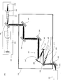
도 3은 도 1의 광원의 타겟 위치와 구동 레이저 시스템 사이에 위치하는 하나의 예시적인 빔 전달 시스템의 블록 다이어그램이다.
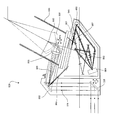
도 4a는 도 3의 빔 전달 시스템의 빔 확대 시스템에 사용된 제1 곡면형 미러의 도면이다.
도 4b는 라인 4A-4A를 따라 취해진 도 4a의 제1의 곡면형 미러의 평면도이다.
도 4c는 라인 4B-4B를 따라 취해진 도 4b의 제1의 곡면형 미러의 측단면도이다.
도 5a는 도 3의 빔 전달 시스템의 빔 확대 시스템에 사용된 제1의 곡면형 미러의 도면이다.
도 5b는 라인 5A-5A를 따라 취해진 도 5a의 제1의 곡면형 미러의 평면도이다.
도 5c는 라인 5B-5B를 따라 취해진 도 5b의 제1의 곡면형 미러의 측단면도이다.
도 6은 도 1의 광원의 타겟 위치와 구동 레이저 시스템 사이에 위치한 하나의 예시적인 빔 전달 시스템의 블록 다이어그램이다.
도 7은 빔 전달 시스템으로부터 타겟 위치까지 광을 포커싱하는 하나의 예시적인 수렴 렌즈의 블록 다이어그램이다.
도 8은 빔 전달 시스템으로부터 타겟 위치까지 광을 포커싱하는 하나의 예시적인 수렴 렌즈의 블록 다이어그램이다.
도 9는 빔 전달 시스템으로부터 타겟 위치까지 광을 포커싱하는 하나의 예시적인 수렴 렌즈의 블록 다이어그램이다.
도 10은 진공 챔버에 설치된 하우징에 설치된 하나의 예시적인 수렴 렌즈의 단면도이고, 이 수렴 렌즈는 도 2 및 3의 빔 전달 시스템에서 사용된다.
도 11a-11c는 도 3-9의 빔 전달 시스템에 사용될 수 있는 예시적인 렌즈앞 미러의 측단면도이다. 1 is a block diagram of a laser generated plasma extreme ultraviolet light source.
FIG. 2A is a block diagram of one exemplary driving laser system that may be used for the light source of FIG. 1.
FIG. 2B is a block diagram of one exemplary driving laser system that may be used for the light source of FIG. 1.
3 is a block diagram of one exemplary beam delivery system located between a target position of the light source of FIG. 1 and a drive laser system.
4A is a view of a first curved mirror used in the beam expanding system of the beam delivery system of FIG. 3.
4B is a top view of the first curved mirror of FIG. 4A taken along
4C is a side cross-sectional view of the first curved mirror of FIG. 4B taken along
5A is a diagram of a first curved mirror used in the beam expanding system of the beam delivery system of FIG. 3.
5B is a top view of the first curved mirror of FIG. 5A taken along
5C is a side cross-sectional view of the first curved mirror of FIG. 5B taken along
6 is a block diagram of one exemplary beam delivery system located between a target position of the light source of FIG. 1 and a drive laser system.
7 is a block diagram of one exemplary converging lens that focuses light from a beam delivery system to a target location.
8 is a block diagram of one exemplary converging lens that focuses light from a beam delivery system to a target location.
9 is a block diagram of one exemplary converging lens that focuses light from a beam delivery system to a target location.
10 is a cross-sectional view of one exemplary converging lens installed in a housing installed in a vacuum chamber, which is used in the beam delivery system of FIGS. 2 and 3.
11A-11C are side cross-sectional views of an exemplary lens front mirror that may be used in the beam delivery system of FIGS. 3-9.
도 1을 참조하면, LPP EUV 광원(100)은 타겟 재료를 EUV 범위 내의 방출선을 가진 원소를 포함하는 플라즈마 상태로 변환하기 위해, 증폭된 광 빔(110)으로 진공 챔버(130) 내의 타겟 위치(105)에 있는 타겟 재료(114)를 조사함으로써 형성된다. 광원(100)은 구동 레이저 시스템(115)의 이득 매체(들) 내의 분포 반전(population inversion)으로 인해 증폭된 광 빔을 산출하는 구동 레이저 시스템(115)을 포함한다.Referring to FIG. 1, the LPP EUV
광원(100)은 또한 레이저 시스템(115)과 타겟 위치(105) 사이에 빔 전달 시스템을 포함하고, 빔 전달 시스템은 빔 트랜스포트 시스템(120) 및 포커스 어셈블리(122)를 포함한다. 빔 트랜스포트 시스템(120)은 레이저 시스템(115)으로부터 증폭된 광 빔(110)을 수신하고, 필요에 따라 증폭된 광 빔(110)을 스티어링하고 변경하고, 증폭된 광 빔(110)을 포커스 어셈블리(122)로 출력한다. 포커스 어셈블리(122)는 증폭된 광 빔(110)을 수신하고, 그 빔(110)을 타겟 위치(105)로 포커싱한다. The
아래에 서술된 바와 같이, 빔 트랜스포트 시스템(120)은, 다른 컴포넌트 중에서도 특히, 회전포물면(paraboloid of revolution)의 비축상 세그먼트인 반사면 형상을 가진 적어도 하나의 미러를 포함한다. 이러한 디자인은 빔(110)이 레이저 시스템(115)과 포커스 어셈블리(122) 사이에서 확대하는 것이 가능하다. 또한 아래에 서술된 바와 같이, 포커스 어셈블리(122)는, 다른 컴포넌트 중에서도 특히, 빔(110)을 타겟 위치(105)상으로 포커싱하는 렌즈 또는 미러를 포함한다. 빔 트랜스포트 시스템(120) 및 포커스 어셈블리(122)에 대한 세부내용을 제공하기에 앞서, 광원(100)의 일반적인 설명이 도 1을 참조하여 제공된다.As described below, the
광원(100)은, 예컨대, 액체 방울, 액체 스트림, 고체 입자 또는 클러스터, 액체 방울 속에 포함된 고체 입자 또는 액체 스트림 내에 포함된 고체 입자 형태로 타겟 재료(114)를 운반하는 타겟 재료 운반 시스템(125)을 포함한다. 타겟 재료(114)는, 예컨대, 물, 주석, 리튬, 크세논, 또는 플라즈마 상태로 변환된 때, EUV 범위 내의 방출선을 가지는 임의의 재료를 포함할 수 있다. 예를 들어, 원소 주석은 순수한 주석(Sn)으로, 주석 컴파운드, 예컨대, SnBr4, SnBr2, SnH4로, 주석 합금, 예컨대, 주석-갈륨 합금, 주석-인듐 합금, 주석-인듐-갈륨 합금, 또는 이러한 합금의 임의의 조합으로 사용될 수 있다. 타겟 재료(114)는 주석과 같은, 상기 원소 중 하나로 코팅된 와이어를 포함할 수 있다. 타겟 재료가 고체 상태이면, 링, 구, 또는 육면체와 같은 임의의 적합한 형상을 가질 수 있다. 타겟 재료(114)는 타겟 재료 운반 시스템(125)에 의해 진공 챔버(130)의 내부로 그리고 타겟 위치(105)로 운반될 수 있다. 타겟 위치(105)는 플라즈마를 생성하기 위해 타겟 재료(114)가 증폭된 광 빔(110)에 의해 조사되는 위치, 즉 조사 위치라고도 한다.
몇몇 구현에서, 레이저 시스템(115)은 하나 이상의 메인 펄스, 및 몇몇 경우에 하나 이상의 프리-펄스(pre-pulses)를 제공하기 위한 하나 이상의 광 증폭기, 레이저, 및/또는 램프를 포함할 수 있다. 각각의 광 증폭기는 높은 이득으로 원하는 파장을 광학적으로 증폭시킬 수 있는 이득 매체, 여기 소스, 및 내부 광학부재를 포함한다. 광 증폭기는 레이저 미러 또는 레이저 캐비티를 형성하는 다른 피드백 디바이스를 포함할 수도 있고, 포함하지 않을 수도 있다. 그러므로, 레이저 시스템(115)은 레이저 캐비티가 존재하지 않을 때에도 레이저의 이득 매체에 내에 분포 반전으로 인한 증폭된 광 빔(110)을 산출한다. 또한, 레이저 시스템(115)은 레이저 시스템(115)에 충분한 피드백을 제공하기 위해 레이저 캐비티가 존재한다면 코히어런트 레이저 빔인 증폭된 광 빔(110)을 산출할 수 있다. 용어 "증폭된 광 빔"은 반드시 코히어런트 레이저 오실레이션은 아니며 단지 증폭된 레이저 시스템(115)으로부터의 광, 및 증폭되고 또한 코히어런트 레이저 오실레이션인 레이저 시스템(115)으로부터의 광 중 하나 이상을 포함한다. In some implementations, the
레이저 시스템(115) 내의 광 증폭기는 CO2를 포함한 충진(filling) 가스를 이득 매체로서 포함할 수 있고, 대략 9100 내지 대략 11000nm의, 특히 대략 10600nm의 파장의 광을 1000 이상의 이득으로 증폭할 수 있다. 레이저 시스템(115)에 사용하기에 적합한 증폭기 및 레이저는 펄스식 레이저 디바이스, 예컨대, 대략 9300nm 또는 대략 10600nm의 방사선을 산출하고, 예컨대, DC 또는 RF 여기를 통해, 예컨대, 10kW 이상의 비교적 높은 파워에서 동작하고, 예컨대, 50kHz 이상의 높은 펄스 반복율의 펄스식 가스방전 C02 레이저 디바이스를 포함할 수 있다. 레이저 시스템(115) 내의 광 증폭기는 또한 높은 파워로 레이저 시스템(115)을 동작할 때 사용될 수 있는 물과 같은 냉각 시스템을 포함할 수 있다.The optical amplifier in the
도 2a를 참조하면, 하나의 특정한 구현으로서, 레이저 시스템(115)은 복수의 증폭 단계를 가진 마스터 오실레이터/파워 증폭기(MOPA)을 가지고, 예컨대, 100 kHz 오퍼레이션이 가능한, 높은 반복율 및 낮은 에너지를 가진 Q-스위칭식 마스터 오실레이터(MO)(200)에 의해 개시되는 시드 펄스를 가진다. MO(200)로부터, 레이저 펄스는 빔 경로(212)를 따라 진행하는 증폭된 광 빔(210)을 산출하기 위해, 예컨대, RF 펌핑된, 고속의 축방향의 플로우, CO2 증폭기(202, 204, 206)를 사용하여 증폭될 수 있다. Referring to FIG. 2A, as one particular implementation, the
3개의 광 증폭기(202, 204, 206)가 도시되어 있으나, 더 적은 증폭기 및 3개 이상의 증폭기가 이러한 구현에 사용될 수 있다. 몇몇 구현에서, 각각의 CO2 증폭기(202, 204, 206)는 내부 미러에 의해 접혀진 10 미터 증폭기 길이를 가진 RF 펌프식 축방향 플로우 CO2 레이저 큐브일 수 있다. Although three
대안으로서, 도 2b를 참조하면, 구동 레이저 시스템(115)은 타겟 재료(114)가 광 캐비티의 하나의 미러로 역할하는 소위 "셀프-타겟팅" 레이저 시스템으로 구성될 수 있다. 몇몇 "셀프-타겟팅" 배열에서, 마스터 오실레이터는 필요하지 않을 수 있다. 레이저 시스템(115)은 빔 경로(262)를 따라 일렬로 배열된 증폭기 챔버(250, 252, 254) 체인을 포함하는데, 각각의 챔버는 자신의 이득 매체 및 여기 소스, 예컨대, 펌핑 전극을 가진다. 각각의 증폭기 챔버(250, 252, 254)는, 예컨대, 10600nm의 파장 λ의 광을 증폭시키기 위한, 예컨대, 1,000-10,000의 결합된 하나의 통과 이득을 가진 RF 펌프식, 고속 축방향 플로우, CO2 증폭기 챔버일 수 있다. 각각의 증폭기 챔버(250, 252, 254)는 단독으로 셋업된 때, 그들이 증폭된 광 빔이 한번 이상 이득 매체를 통과하기 위해 필요한 광학 컴포넌트를 포함하지 않도록, 레이저 캐비티(공진기) 없이 설계될 수 있다. 그럼에도 불구하고, 앞서 언급한 바와 같이, 레이저 캐비티는 아래와 같이 형성될 수 있다. As an alternative, referring to FIG. 2B, the
이러한 구현에서, 레이저 캐비티는 레이저 시스템(115)에 후방 부분 반사 광학부재(264)를 추가하고 타겟 위치(105)에 타겟 재료(114)를 놓음으로써 형성될 수 있다. 광학부재(264)는 대략 10600nm의 파장(CO2 증폭기 챔버가 사용되었을 때 증폭된 광 빔(110)의 파장)에 대하여 대략 95%의 반사율을 가진 평면 미러, 곡면형 미러, 위상 공액(phase-conjugate) 미러, 또는 코너 반사기일 수 있다. In such an implementation, the laser cavity may be formed by adding the rear partially
타겟 재료(114) 및 후방 부분 반사 광학부재(264)는 증폭된 광 빔(110)의 일부를 레이저 캐비티로부터 레이저 시스템(115)으로 다시 반사하는 역할을 한다. 그러므로, 타겟 위치(105)에 타겟 재료(114)의 존재는 레이저 시스템(115)이 코히어런트 레이저 오실레이션을 만들게 하기 위해 충분한 피드백을 제공하고, 이러한 경우, 증폭된 광 빔(110)은 레이저 빔으로 고려될 수 있다. 타겟 재료(114)가 타겟 위치(105)에 존재하지 않을 때, 레이저 시스템(115)은 여전히 증폭된 광 빔(110)을 산출하기 위해 펌핑될 수 있으나, 광원(100) 내의 일부 다른 컴포넌트가 충분한 피드백을 제공하지 않는다면 코히어런트 레이저 오실레이션을 만들지는 못한다. 특히, 증폭된 광 빔(110)과 타겟 재료(114)의 교차 동안, 타겟 재료(114)는 빔 경로(262)를 따라 광을 반사시킬 수 있고, 증폭기 챔버(250, 252, 254)를 통과하는 광 캐비티를 형성하기 위해 광학부재(264)와 협력한다. 이러한 배열은 타겟 재료(114)의 반사율이 광 이득이 캐비티 내의 광 손실을 초과하지 않을 만큼 충분하게 구성되어, 각각의 증폭기 챔버(250, 252, 254) 내의 이득 매체가 여기된 때, 타겟 재료(114)를 조사하는 동안 레이저 빔을 발생시키고, 플라즈마를 생성하고, 챔버(130) 내의 EUV 광 방출선을 산출한다. 이러한 배열을 통해, 광학부재(264), 증폭기(250, 252, 254), 및 타겟 재료(114)는 타겟 재료(114)가 광 캐비티의 하나의 미러(소위 플라즈마 미러 또는 기계식 q-스위치)로서 역할하는 소위 "셀프 타겟팅" 레이저 시스템을 형성하도록 결합한다. 셀프 타겟팅 레이저 시스템은 "EUV 광원용 구동 레이저 전달 시스템"란 제목의 2006년 10월 13일에 출원된 미국출원번호 제11/580,414호에 개시되어 있다.The
애플리케이션에 따라, 다른 타입의 증폭기 또는 레이저, 예컨대, 고출력 및 높은 펄스 반복률로 동작하는 엑시머 또는 분자 플루오르 레이저가 적합할 수 있다. 예는, 예컨대, 섬유 또는 디스크 형태의 이득 매체를 가진 솔리드 스테이트 레이저, 예컨대, 미국특허번호 제6,625,191호; 제6,549,551호; 및 제6,567,450호에서 볼 수 있는 MOPA 구성의 엑시머 레이저 시스템, 하나 이상의 챔버, 예컨대, 하나의 오실레이터 챔버와 하나 이상의 증폭 챔버(증폭 챔버들은 병렬 또는 직렬일 수 있다)를 구비한 엑시버 레이저, 마스터 오실레이터/파워 오실레이터(MOPO) 배열, 파워 오실레이터/파워 증폭기(POPA) 배열; 또는 하나 이상의 엑시머 또는 분자 플루오르 증폭기 또는 오실레이터 챔버를 시딩(seed)하는 솔리드 스테리트 레이저가 적합할 수 있다. 다른 설계도 가능하다. Depending on the application, other types of amplifiers or lasers, such as excimer or molecular fluorine lasers operating at high power and high pulse repetition rate, may be suitable. Examples include, for example, solid state lasers having gain media in the form of fibers or discs, such as US Pat. No. 6,625,191; 6,549,551; 6,549,551; And an excimer laser system in a MOPA configuration as shown in US Pat. No. 6,567,450, an excimer laser having one or more chambers, such as one oscillator chamber and one or more amplification chambers (amplification chambers may be in parallel or in series), master oscillator Power oscillator (MOPO) arrangement, power oscillator / power amplifier (POPA) arrangement; Alternatively, solid state lasers that seed one or more excimer or molecular fluorine amplifier or oscillator chambers may be suitable. Other designs are possible.
조사 위치에서, 포커스 어셈블리(122)에 의해 적절하게 포커싱된 증폭된 광 빔(110)은 타겟 재료(114)의 구성에 의존하는 일정한 특성을 가진 플라즈마를 생성하기 위해 사용된다. 이러한 특성은 플라즈마에 의해 생성된 EUV 광의 파장 및 플라즈마로부터 떨어진 찌꺼기의 양을 포함할 수 있다.At the irradiation position, the amplified
광원(100)은 증폭된 광 빔(110)이 통과하여 타겟 위치(105)에 도달할 수 있게 하기 위한 애퍼어처(140)를 구비한 수집 미러(135)를 포함한다. 수집 미러(135)는, 예컨대, 타겟 위치(105)에 제1 초점, 중간 위치(145)에 제2 초점(중간 초점이라고도 함)을 구비한 타원형 미러일 수 있는데, EUV 광은 광원(100)으로부터 출력될 수 있고, 예컨대, (도시되지 않은) 집적회로 리소그래피 툴로 입력될 수 있다. 광원(100)은 또한 증폭된 광 빔(110)이 타겟 위치(105)에 도달할 수 있게 하면서, 포커스 어셈블리(122) 및/또는 빔 전달 시스템(120)로 들어가는 플라즈마 발생된 찌꺼기의 양을 줄이기 위해, 수집 미러(135)로부터 타겟 위치(105)를 향해 점점 가늘어지는(taper) 개방형(open-ended)의 속이 빈 원뿔형 슈라우드(150)를 포함할 수 있다. 이러한 목적으로, 타겟 위치(105)를 향해 지향된 슈라우드 내에 가스 흐름이 제공될 수 있다. The
광원(100)은 또한 방울 위치 탐지 피드백 시스템(156), 레이저 컨트롤 시스템(157), 및 빔 컨트롤 시스템(158)에 연결되어 있는 마스터 컨트롤러(155)를 포함할 수 있다. 광원(100)은, 예컨대, 타겟 위치(105)에 상대적인, 방울의 위치를 나타내는 출력을 제공하고, 그로부터 방울 위치 오차가 방울대방울 기준으로 또는 평균적으로 계산될 수 있는, 예컨대, 방울 위치 및 궤적을 계산할 수 있는, 방울 위치 탐지 피드백 시스템(156)에 이러한 출력을 제공하는 하나 이상의 타겟 또는 방울 이미저(160)를 포함할 수 있다. 그러므로, 방울 위치 탐지 피드백 시스템(156)은 마스터 컨트롤러(155)에 대한 입력으로서 방울 위치 오차를 제공한다. 그러므로, 마스터 컨트롤러(155)는, 예컨대, 레이저 타이밍 회로를 컨트롤하기 위해, 사용될 수 있는 레이저 컨트롤 시스템(157)에, 그리고/또는 챔버(130) 내의 빔 초점 스폿의 위치 및/또는 초점 파워를 변경하기 위해 빔 트랜스포트 시스템(120)의 증폭된 광 빔 위치 및 형상을 컨트롤하기 위해 빔 컨트롤 시스템(158)에, 레이저 위치, 방향, 및 타이밍 보정 신호를 제공할 수 있다.The
타겟 재료 운반 시스템(125)은, 예컨대, 바람직한 타겟 위치(105)에 도달한 방울의 오차를 보정하기 위해 운반 메카니즘(127)에 의해 방출되는 방울의 방출 포인트를 수정하기 위해, 마스터 컨트롤러(155)로부터의 신호에 응답하여 동작가능한 타겟 재료 운반 컨트롤 시스템(126)을 포함한다.The target
또한, 광원(100)은 하나 이상의 EUV 광 파라미터를 측정하는 광원 탐지기(165)를 포함할 수 있는데, 이러한 파라미터들은 펄스 에너지, 파장의 함수인 에너지 분포, 특정한 파장 대역 내의 에너지, 특정한 파장 대역을 벗어난 에너지, 및 EUV 강도 및/또는 평균 파워의 각도 분포를 포함하지만, 이에 제한되지는 않는다. 광원 탐지기(165)는 마스터 컨트롤러(155)에 의해 사용하기 위한 피드백 신호를 생성한다. 이러한 피드백 신호는, 예컨대, 효과적이고 효율적인 EUV 광 발생을 위해 올바른 위치 및 시간에 방울들을 적절하게 인터셉트하기 위해, 레이저 펄스의 타이밍 및 초점과 같은 파라미터 내의 오차를 나타낼 수 있다.In addition, the
광원(100)은 또한 광원(100)의 다양한 섹션들을 정렬시키기 위해, 또는 증폭된 광 빔(110)을 타겟 위치(105)로 스티어링하는 것을 돕기 위해 사용될 수 있는 가이드 레이저(175)를 포함한다. 가이드 레이저(175)와 관련하여, 광원(100)은 가이드 레이저(175)로부터의 광 및 증폭된 광 빔(110)의 일부분을 샘플링하기 위해 포커스 어셈블리(122) 내에 놓여진 계측 시스템(124)을 포함한다. 다른 구현으로서, 계측 시스템(124)은 빔 트랜스포트 시스템(120) 내에 놓여진다. The
계측 시스템(124)은 광의 서브셋을 샘플링하거나 다시 방향조절하는 광학 엘리먼트를 포함할 수 있고, 이러한 광학 엘리먼트는 가이드 레이저 빔 및 증폭된 광 빔(110)의 파워를 견딜 수 있는 임의의 재료로 만들어진다. 예를 들어, 계측 시스템(124)내의 샘플 광학 엘리먼트는 반사방지 코팅으로 코팅된 셀렌화 아연(ZnSe)으로 이루어진 기판을 포함할 수 있다. 계측 시스템(124) 내의 샘플 광학 엘리먼트는 진단 목적으로 가이드 레이저(175)로부터 그리고 증폭된 광 빔(110)으로부터 일부의 광을 분리하기 위해, 증폭된 광 빔(110)의 세로방향에 상대적인 각도로 놓여진 회절 격자일 수 있다. 증폭된 광 빔(110)과 가이드 레이저(175)의 빔의 파장이 서로 구별되기 때문에, 그들은 빔의 분리를 가능하게 하기 위해 회절 격자로부터 분리된 각도로 나오도록 방향조절될 수 있다. 빔 분석 시스템은 마스터 컨트롤러(155)가 가이드 레이저(175)로부터의 샘플링된 광을 분석하고, 이러한 정보를 빔 컨트롤 시스템(158)을 통해 포커스 어셈블리(122) 내의 컴포넌트들을 조절하기 위해 사용하므로, 계측 시스템(124) 및 마스터 컨트롤러(155)로 형성될 수 있다. 다른 구현으로서, 계측 시스템(124)은 가이드 레이저(175)로부터 증폭된 광 빔(110)을 분리하고, 개별적인 분석을 위해 제공하기 위해, 포커스 어셈블리(122) 내에 놓여진 하나 이상의 이색성 미러를 포함한다. 이러한 계측 시스템은 사건번호 002-017001/2009-0027-01가 할당된 본 출원과 동시에 출원된 "극자외선 광원용 계측 시스템"에 서술되어 있다. The
그러므로, 요약하자면 광원(100)은 타겟 재료를 EUV 범위의 광을 방출하는 플라즈마로 변환하기 위해 타겟 위치(105)에 있는 타겟 재료로 지향되는 증폭된 광 빔(110)을 산출한다. 증폭된 광 빔(110)은 아래에 더욱 상세하게 서술된 바와 같이, 레이저 시스템(115)의 설계 및 특성을 기초로 결정된 특정한 파장에서 동작한다. 또한, 증폭된 광 빔(110)은 타겟 재료가 코히어런트 레이저 광을 산출하기 위해 레이저 시스템(115)으로 충분한 피드백을 제공할 때, 또는 구동 레이저 시스템(115)이 레이저 캐비티를 형성하기 위해 적합한 광 피드백을 포함한다면, 레이저 빔이 될 수 있다.Thus, in summary, the
앞서 서술한 바와 같이, 구동 레이저 시스템(115)은 적어도 하나의 증폭기, 및 수개의 광학 컴포넌트(예컨대, 대략 20 내지 50개의 미러)를 포함하는데, 빔 전달 시스템(120) 및 포커스 어셈블리(122)는, 예컨대, 미러, 렌즈, 및 프리즘과 같은 수개의 광학 컴포넌트를 포함한다. 이러한 광학 컴포넌트들은 모두 증폭된 광 빔(110)의 효율적인 형성 및 타겟 위치(105)로의 증폭된 광 빔(110)의 출력을 허용하기 위해, 증폭된 광 빔(110)의 파장을 포함하는 파장 범위를 가진다. 또한, 하나 이상의 광학 컴포넌트들은 기판상의 다층 유전체 반사방지 간섭 코팅과 함께 형성될 수 있다.As described above, the
도 3을 참조하면, 하나의 예시적인 빔 전달 시스템(300)은 구동 레이저 시스템(305)과 타겟 위치(310) 사이에 놓여지고, 빔 전달 시스템은 빔 트랜스포트 시스템(315) 및 포커스 어셈블리(320)를 포함한다. 빔 트랜스포트 시스템(315)은 구동 레이저 시스템(305)에 의해 산출된 증폭된 광 빔(325)을 수신하고, 증폭된 광 빔(325)을 재방향조절하고 확대한 후, 확대되고 재방향조절된 증폭된 광 빔(325)을 포커스 어셈블리(320)로 보낸다. 포커스 어셈블리(320)는 증폭된 광 빔(325)을 타겟 위치(310)로 모은다.Referring to FIG. 3, one exemplary
빔 트랜스포트 시스템(315)은 증폭된 광 빔(325)의 방향을 변경하는 (때때로 폴드 미러라고도 하는) 하나의 세트의 미러(330, 332, 334, 336, 및 338)를 포함한다. 폴드 미러(330, 332, 334, 336, 338)는 증폭된 광 빔(325)을 반사하는데 적합한 임의의 기판 및 코팅으로 이루어질 수 있다. 그러므로, 폴드 미러는 증폭된 광 빔(325)의 파장의 대부분의 광을 반사하도록 선택된 기판 및 코팅으로 이루어질 수 있다. 몇몇 구현에서, 하나 이상의 폴드 미러(330, 332, 334, 336, 338)는 무산소 고전도율(OFHC) 구리 기판 위에 펜실베니아 색슨버그의 II-VI 인프러레드에 의해 제조되는 최대 금속 반사(MMR) 코팅과 같은 높은 반사율의 코팅으로 이루어진다. 폴드 미러(330, 332, 334, 336, 338)용으로 사용될 수 있는 다른 코팅은 금 및 은을 포함하고, 코팅이 적용될 수 있는 다른 기판은 실리콘, 몰리브덴, 및 알루미늄을 포함한다. 하나 이상의 폴드 미러(330, 332, 334, 336, 338)는, 예컨대, 기판을 통해 물 또는 몇몇 다른 적합한 냉각제를 흐르게 함으로써, 수냉각될 수 있다.
빔 트랜스포트 시스템(315)은 또한 빔 확대 시스템(340)을 빠져나오는 증폭된 광 빔(325)의 가로 크기가 빔 확대 시스템(340)으로 들어가는 증폭된 광 빔(325)의 가로 크기보다 더 크도록, 증폭된 광 빔(325)을 확대하는 빔 확대 시스템(340)을 포함한다. 빔 확대 시스템(340)은 타원 포물면의 비축상 세그먼트인 반사면을 가진 적어도 하나의 곡면형 미러를 포함한다(이러한 미러를 비축상 포물면 미러라고도 한다). 빔 확대 시스템(340)은 증폭된 광 빔(325)을 재방향조절하고 확대하거나 시준(collimate)하도록 선택된 다른 광학 컴포넌트를 포함할 수 있다. 빔 확대 시스템(340)에 대한 다양한 설계는 도 3, 4a-c, 5a-c, 및 6을 참조하여 아래에 설명된다. The
도 3에 도시된 바와 같이, 빔 확대 시스템(340)은 타원 포물면의 비축상 세그먼트인 반사면(343)을 가진 제1 곡면형 미러(342), 및 타원 포물면의 비축상 세그먼트인 반사면(347)을 가진 제2 곡면형 미러(346)를 포함한다. 곡면형 미러(342, 346)의 형상은 서로 상보적(complementary)이 되도록 선택되고, 곡면형 미러(342, 346)의 상대적 위치는 증폭된 광 빔(325)의 수집 효율을 증가시키도록 조절된다. 곡면형 미러(342, 346)에 대한 더욱 세부적인 내용은 각각 도 4a-c 및 5a-c를 설명할 때 아래에 제공된다. As shown in FIG. 3, the
또한 도 3에 도시된 바와 같이, 포커스 어셈블리(320)는 최종 폴드 미러(350), 및 미러(350)로부터 반사된 증폭된 광 빔(325)을 타겟 위치(310)로 포커싱하도록 구성되고 배열된 수렴 렌즈(355)를 구비한 포커싱 엘리먼트를 포함한다. 최종 폴드 미러(350)는 증폭된 광 빔(325)의 파장에서 반사율이 높은 코팅을 가진 기판으로 이루어질 수 있다. 예컨대, 미러(350)는 무산소 고전도율(OFHC) 구리 기판 위에 펜실베니아 색슨버그의 II-VI 인프러레드에 의해 제조되는 최대 금속 반사(MMR) 코팅을 가질 수 있다. 미러(350)용으로 사용될 수 있는 다른 코팅은 금 및 은을 포함하고, 코팅이 적용될 수 있는 다른 기판은 실리콘, 몰리브덴, 및 알루미늄을 포함한다. 렌즈(355)는 증폭된 광 빔(325)의 파장을 투과할 수 있는 재료로 이루어진다. 몇몇 구현에서, 렌즈(355)는 ZnSe로 이루어진다. 수렴 렌즈(355)의 세부사항은 도 7-9를 설명할 때 제공된다.Also shown in FIG. 3, the
포커스 어셈블리(320)는 또한 렌즈(355)로부터 반사된 광(365)을 캡처하는 계측 시스템(360)을 포함할 수 있다. 이러한 캡처된 광은, 예컨대, 증폭된 광 빔(325)의 위치를 판정하기 위해, 그리고 증폭된 광 빔(325)의 초점 길이의 변화를 모니터링하기 위해 가이드 레이저(175)로부터의 광 및 증폭된 광 빔(325)의 특성을 분석하기 위해 사용될 수 있다. 구체적으로, 캡처된 광은 렌즈(355) 상의 증폭된 광 빔(325)의 위치에 관한 정보를 제공하기 위해, 그리고 렌즈(355)의 온도 변화(예컨대, 가열)로 인한 렌즈(355)의 초점 길이 변화를 모니터하기 위해 사용될 수 있다.
렌즈(355)는 미러(350)에서 타겟 위치(310)의 바람직한 위치까지 반사된 증폭된 광 빔(325)의 포커싱을 가능하게 하거나 용이하게 하기 위한 메니스커스 렌즈(meniscus lens)일 수 있다. 또한, 렌즈(355)는 렌즈(355)로부터 반사된 타이트하게 포커싱된 투과된 증폭된 광 빔(325) 및 타이트하게 포커싱된 광(365)을 동시에 제공하기 위해, 그 각각의 면에 대한 비구면 보정을 포함할 수 있다. 렌즈(355)는 포물면의 온축(on-axis) 세그먼트인 적어도 하나의 면을 가지도록 설계될 수 있다.
각각의 폴드 미러(330, 332, 334, 336, 338)는 증폭된 광 빔(325)을 임의의 적합한 각도만큼, 예컨대, 대략 90도로 재방향조절할 수 있다. 또한, 적어도 2개의 폴드 미러(330, 332, 334, 336, 338)는 타겟 위치(310)로의 증폭된 광 빔(325)의 액티브 포인팅 컨트롤을 제공하기 위해 마스터 컨트롤러(155)에 의해 컨트롤될 수 있는 모터에 의해 구동되는 이동가능한 마운트의 사용을 통하여 이동가능할 수 있다. 이동가능한 폴드 미러는 렌즈(355) 상의 증폭된 광 빔(325)의 위치 및 타겟 재료에 있는 증폭된 광 빔(325)의 초점을 유지하기 위해 조절될 수 있다. Each
빔 전달 시스템(300)은 또한 빔 전달 시스템(300)의 (폴드 미러(330, 332, 332, 334, 336, 338), 곡면형 미러(342, 346), 및 최종 폴드 미러(350)와 같은) 하나 이상의 컴포넌트의 위치 및 각도 또는 포지션을 정렬하기 위해 셋업시 사용되는 정렬 레이저(370)를 포함할 수 있다. 정렬 레이저(370)는 컴포넌트의 시각적 정렬을 돕기 위해 가시광 스펙트럼 내에서 동작하는 다이오드 레이저일 수 있다. 정렬 레이저(370)는 가시광을 반사하고 적외선 광을 투과하는 이색성 빔 결합기(371)로부터 반사된다. 이는 정렬 빔이 증폭된 레이저 빔과 동시에 진행하는 것을 허용한다.
빔 전달 시스템(300)은 또한 탐지 디바이스(375)에서 탐지될 수 있는 진단 빔(380)을 형성하기 위해 구동 레이저 시스템(305)의 전면에서 반사되는 광과 같은, 타겟 위치(310)에서 타겟 재료(114)로부터 반사되는 광을 모니터하는 카메라와 같은 탐지 디바이스(375)를 포함할 수 있다. 탐지 디바이스(375)는 (타겟 재료(예컨대, 방울)의 흐름 방향인) x축 방향을 따른 플라즈마의 위치에 대한 피드백을 제공하기 위해 마스터 컨트롤러(155)에 연결될 수 있다. 그로 인해, 마스터 컨트롤러(155)는 증폭된 광 빔(325)의 위치를 타겟 재료(114)와 더 잘 일치하거나 오버랩하도록 조절하기 위해 빔 전달 시스템(300) 내의 하나 이상의 컴포넌트(예컨대, 미러(350) 및/또는 렌즈(355))의 위치를 조절할 수 있다.
또한 도 4a-c를 참조하면, 제1 곡면형 미러(342)는 타원 포물면(410)의 세그먼트(405)로부터 형성된 반사면(343)을 가진 발산 미러이다. 반사면(343)은 포물면 세그먼트(405)의 내측면으로부터 형성된다. 타원 포물면(410)은 회전축(415)을 가진 회전 포물면이고, 세그먼트(405) 내의 "비축상 세그먼트"이고, 반사면(400)은 포물면(410)의 회전축을 제외한 포물면(410)의 영역으로부터 형성된다. 미러(342)(더욱 상세하게는, 반사면(343))는 미러(342)로부터 반사되는 증폭된 광 빔(325)의 빔 반경이 빔이 미러(342)로부터 멀어지도록 진행할 때 증가하도록, 증폭된 광 빔(325)의 시준된 파면을 발산하게 한다는 점에서 발산형이다.Referring also to FIGS. 4A-C, the first
제1 곡면형 미러(342)는 증폭된 광 빔(325)을 반사하기에 적합한 임의의 기판 및 코팅으로 이루어질 수 있다. 그러므로, 이 미러는 증폭된 광 빔(325)의 파장의 광을 반사하도록 선택된 기판 및 코팅으로 이루어질 수 있다. 제1 곡면형 미러(342)는 미러(342)의 기판을 통해 흐를 수 있는 물과 같은 유체 냉각제를 통해 냉각될 수 있다. 제1 곡면형 미러(342)의 반사면(343)은 무산소 고전도율(OFHC) 구리 기판 위에 펜실베니아 색슨버그의 II-VI 인프러레드에 의해 제조되는 최대 금속 반사(MMR) 코팅으로 형성될 수 있다. The first
또한, 도 5a-c를 참조하면, 제2 곡면형 미러(346)는 타원 포물면(510)의 세그먼트(505)로부터 형성된 반사면(347)을 가진 수렴 미러이다. 반사면(347)은 포물면 세그먼트(505)의 외측면으로부터 형성된다. 타원 포물면(510)은 회전축(515)을 가진 회전 포물면일 수 있고, 그러므로 세그먼트(505)는 세그먼트(505) 및 반사면(500)이 포물면(510)의 회전축(515)을 제외한 포물면(510)의 영역으로 형성된다는 점에서 "비축상 세그먼트"이다. 미러(346)(더욱 상세하게는, 반사면(347))는 미러가 증폭된 광 빔(325)의 빔 반경이 빔이 미러(346)로부터 멀어지도록 진행할 때 감소하도록 증폭된 광 빔(325)의 시준된 파면이 수렴하게 한다는 점에서 수렴형이다. 수렴 미러(346)는 또한 증폭된 광 빔(325)의 발산하는 파면이 미러(346)로부터 반사할 때 시준되게 하여, 미러(346)로부터 반사된 발산하는 증폭된 광 빔(325)의 빔 반경이 빔이 미러(346)로부터 멀어지게 진행할 때 동일하게 유지되게 한다.Referring also to FIGS. 5A-C, the second
제2 곡면형 미러(346)는 증폭된 광 빔(325)을 반사하기에 적합한 임의의 기판 및 코팅으로 이루어질 수 있다. 그러므로, 미러는 증폭된 광 빔(325)의 파장의 광을 반사하도록 선택된 기판 및 코팅으로 이루어질 수 있다. 제2 곡면형 미러(346)의 반사면(347)은 무산소 고전도율(OFHC) 구리 기판 위에 펜실베니아 색슨버그의 II-VI 인프러레드에 의해 제조되는 최대 금속 반사(MMR)일 수 있다. 제2 곡면형 미러(346)는 미러(346)의 기판을 통해 흐를 수 있는 물과 같은 유체 냉각제로 냉각될 수 있다. The second
제1 곡면형 미러(342) 및 제2 곡면형 미러(346)의 조합은, 예컨대, 대략 3.6배의 증폭된 광 빔(325)의 확대를 제공하고, 이러한 확대는 예컨대, 3.6배의 빔의 발산을 줄인다. 적어도 하나의 비축상 포물면 미러를 구비한 빔 확대 시스템(340)의 설계는 빔 확대를 위해 구형 미러를 사용한 종래의 배열과 비교할 때 빔 트랜스포트 시스템(315) 내에 더욱 작은 배열을 가능하게 한다. 증폭된 광 빔(325)은, 빔 확대 시스템(340)이 적어도 하나의 비축상 포물면 미러(예컨대, 제1 곡면형 미러(342), 제2 곡면형 미러(346), 두 미러(342, 346)의 조합, 또는 곡면형 미러(342, 346) 중 하나와 렌즈의 조합)를 포함하기 때문에, 구형 미러를 사용한 종래의 빔 확대기에서 가능했던 것보다 더 먼 거리를 더 적은 발산을 가지고 트랜스포트될 수 있다. 또한, 비축상 포물면 미러는 종래의 빔 확대기에 사용된 구형 미러와 비교할 때 증폭된 광 빔(325)의 향상된 품질의 파면(예컨대, 파면이 평면 파면과 더 근접하도록 감소된 수차)을 제공한다. The combination of the first
도 6을 참조하면, 다른 구현으로서, 빔 전달 시스템(600)은 구동 레이저 시스템(605)과 타겟 위치(610) 사이에 위치한다. 빔 전달 시스템(600)은 빔 트랜스포트 시스템(615) 및 포커스 어셈블리(620)를 포함한다. 빔 트랜스포트 시스템(615)은 구동 레이저 시스템(605)에 의해 증폭된 광 빔(625)을 수신하고, 증폭된 광 빔(625)을 다시 방향조절하고 확대한 후, 확대되고 다시 방향조절된 증폭된 광 빔(625)을, 증폭된 광 빔(625)을 타겟 위치(610)로 포커싱하는 포커스 어셈블리(620)로 향하게 한다. 포커스 어셈블리(620)는 증폭된 광 빔(625)을 타겟 위치(610)로 포커싱하는 수렴 렌즈를 포함할 수 있다. 이러한 수렴 렌즈는 2009년 12월 15일에 출원된 "극자외선 광원을 위한 계측법"이란 제목의 미국특허 출원번호 제12/637,961호에 서술되어 있다.Referring to FIG. 6, as another implementation, the
빔 트랜스포트 시스템(615)은 증폭된 광 빔(625)를 확대시키는 빔 확대 시스템(640), 및 앞서 서술한 폴드 미러와 같은 하나의 세트의 추가적인 방향조절 광학 컴포넌트(645)를 포함한다. 빔 확대 시스템(640)은 타원 포물면의 비축상 세그먼트인 반사면을 가진 곡면형 미러(642) 및 구동 레이저 시스템(605)의 출력부에 위치한 발산 렌즈(646)를 포함한다. 발산 렌즈(646)는 증폭된 광 빔(110)의 파장의 광을 투과시키고 증폭된 광 빔(110)의 강도로 인해 누적될 수 있는 열에 견질 수 있는 임의의 재료로 이루어질 수 있다. 몇몇 구현에서, 발산 렌즈(646)는 다이아몬드로 이루어지고, 2개의 오목면을 형성하도록 연마된다. 발산 렌즈(646)는 구동 레이저 시스템(605)의 출력 윈두오로서 구성될 수 있다.The
도 7을 참조하면, 하나의 예시적인 포커스 어셈블리(670)는 최종 폴드 미러(750) 및 미러(750)로부터 반사된 증폭된 광 빔(325)을 챔버(730) 내의 타겟 위치(710)로 포커싱하도록 구성되고 배열된 수렴 렌즈(755)를 구비한 포커싱 엘리먼트를 포함한다. 본 예에서, 수렴 렌즈(755)는 양볼록 렌즈(double convex or biconvex lens)이지만, 대안으로서 볼록-오목 렌즈일 수도 있다. 렌즈(755)는 렌즈 하우징(794)의 개구가 챔버 벽(790)의 개구와 나란하도록 챔버(730)의 벽(790)에 설치되어 있는 렌즈 하우징(794) 내에 설치되고, 렌즈(755)는 챔버(730) 내부에 유지된 진공과 챔버(730) 외부의 정화된 환경 사이에 윈도우로서 역할한다. 벨로우(792)는 광 빔(325)의 방향에 상대적인 3 방향(광 빔(325)의 방향을 따라 뻗어 있는 축방향 또는 세로 방향, 및 축방향에 대하여 가로방향인 2개의 방향) 중 하나 이상의 방향을 따른 렌즈(755)의 이동을 용이하게 하기 위해 진공 챔버 벽(790)과 하우징(794) 사이에 놓여질 수 있다. Referring to FIG. 7, one exemplary focus assembly 670 focuses the
포커스 어셈블리(720)는 렌즈(755)로부터 반사된 광(765)을 캡처하고 미러(750)의 중앙영역 내의 개구를 통해 투과시키는 계측 시스템(760)을 포함할 수 있다. The
극자외선 광 챔버(730)는 증폭된 광 빔(325)이 타겟 위치(710)를 가로질러 타겟 재료를 타격할 때 타겟 위치(710)에 있는 타겟 재료로부터 방출되는 극자외선 광을 수집하도록 구성된 극자외선 광 수집기(735)를 하우징한다.The extreme ultraviolet
도 8을 참조하면, 다른 구현으로서, 포커스 어셈블리(820)는 최종 폴드 미러(850) 및 최종 폴드 미러(850) 및 미러(850)로부터 반사된 증폭된 광 빔(325)을 챔버(830) 내의 타겟 위치(810)로 포커싱하도록 구성되고 배열된 수렴 렌즈(855)를 구비한 포커싱 엘리먼트를 포함한다. 포커스 어셈블리(820)는 또한 렌즈(855)로부터 포커싱된 광을 타겟 위치(810)로 다시 방향조절하기 위해 설치된 이동가능한 미러(88)를 포함한다. 본 구현에서, 수렴 렌즈(855)는 챔버(830) 내에 놓여진 메니커스 렌즈이지만, 수렴 렌즈는 평철(plano-convex) 렌즈일 수 있다. 포커스 어셈블리(820)는 또한 렌즈 (855)로부터 반사된 후, 증폭된 광 빔(325)의 방향과 상이한 방향을 따라 미러(850)의 중앙 영역 내의 오프셋 파셋(facet)으로부터 반사된 광(865)을 캡처하는 계측 시스템(860)을 포함할 수 있다. Referring to FIG. 8, as another implementation, the
극자외선 광 진공 챔버(830)는 증폭된 광 빔(325)이 타겟 위치(810)를 가로질러 타겟 재료를 타격할 때 타겟 위치(810)에 있는 타겟 재료로부터 방출되는 극자외선 광을 수집하도록 구성된 극자외선 광 수집기(835)를 하우징한다.The extreme ultraviolet
도 9를 참조하면, 다른 구현으로서, 포커스 어셈블리(920)는 최종 폴드 미러(950) 및 미러(950)로부터 그리고 다른 중간 미러(985)로부터 반사된 증폭된 광 빔(325)을 챔버(930) 내의 타겟 위치(910)로 포커싱하도록 구성되고 배열된 수렴 렌즈(955)를 구비한 포커싱 엘리먼트를 포함한다. 본 구현에서, 수렴 렌즈(955)는 렌즈(955)가 챔버(930) 내부에 유지된 진공과 챔버(930) 외부의 정화된 환경 사이의 윈도우로 역할하도록 챔버(930)의 벽(990) 내에 위치하는 평철 렌즈이다. (도시되지 않은) 벨로우는 광 빔(325)에 상대적인 3 방향(광 빔(325)의 방향을 따라 뻗은 축방향, 및 축방향에 대하여 가로방향인 2 방향) 중 하나 이상의 방향을 따른 렌즈(955)의 이동을 용이하게 하기 위해 진공 챔버 벽(990)과 렌즈(955) 사이에 놓여질 수 있다. 포커스 어셈블리(920)는 또한 렌즈(955)로부터 반사되고, 미러(950) 내의 중앙 개구를 통해 방향조절된 광(965)을 캡처하는 계측 시스템(960)을 포함할 수 있다. Referring to FIG. 9, as another implementation, the
극자외선 광 진공 챔버(930)는 증폭된 광 빔(325)이 타겟 위치(910)를 가로질러 타겟 재료를 타격할 때 타겟 위치(910)에 있는 타겟 재료로부터 방출되는 극자외선 광을 수집하도록 구성된 극자외선 광 수집기(935)를 하우징한다.The extreme ultraviolet
도 7-9의 구현에서, 계측 시스템(760, 860, 960)은 광(765, 865, 965)을 이들 빔 각각의 개별적인 분석을 허용하기 위해 2개의 빔(증폭된 광 빔(325)의 파장에 있는 빔인 제1 빔(762, 862, 962)과 가이드 레이저(175)의 파장에 있는 빔인 제2 빔(763, 863, 963))으로 분리시키는 광학 컴포넌트(761, 861, 961)를 포함한다. 도 7-9에 도시된 구현에서, 광학 컴포넌트(761, 861, 961)는 증폭된 광 빔(325)의 파장(예컨대, 대략 10600 nm)의 광을 반사하고, 가이드 레이저(175)에 의해 생성된 광의 파장(예컨대, 대략 11150 nm)의 광을 투과시키는 이색성 미러이다. 계측 시스템(760, 860, 960)은 또한 분리된 광 빔을 수신하고 빔의 특성을 분석하는 탐지기(764, 864, 964)(예컨대, 초전 솔리드 스테이트 탐지기 어레이)를 포함한다. 탐지기(764, 864, 964)는 분석된 빔 특징의 신호를 출력하고, 이 출력 신호는 출력 신호는 렌즈(755, 855, 955)에 그리고/또는 빔 전달 시스템(700, 800, 900)의 하나 이상의 이동가능한 미러(예컨대, 미러(750, 850, 950))에 적용하기 위한 위치 조절의 크기를 결정하여, 증폭된 광 빔(325)과 타겟 재료(114)의 오버랩을 증가시키고, 그로 인해 EUV 산출량을 증가시키기 위해, 출력 신호를 사용하는 마스터 컨트롤러(155)로 전송된다. 계측 시스템(760, 860, 960)은 탐지기(764, 864, 964)에 도달하기 전에 다른 방식으로 광을 조절하기 위해 필터, 렌즈, 빔 스플리터, 및 미러와 같은 다른 광학 컴포넌트를 포함할 수 있다. 계측 시스템(760, 860, 960)은 2009년 12월 15일에 출원된 "극자외선 광원을 위한 계측법"이란 제목의 미국특허 출원번호 제12/637,961호에 상세하게 도시되고 서술되어 있다.In the implementations of FIGS. 7-9, the
일반적으로, 수렴 렌즈(355, 755, 855, 955)는 구면 수차 및 구형 렌즈에서 발생할 수 있는 다른 광 수차를 줄이기 위해 비구면 렌즈일 수 있다. In general, the converging
앞서 보여진 구현에서, 수렴 렌즈(755, 855, 955)는 챔버 외부에 위치하지만 챔버 벽에 설치된 하우징 내에 렌즈를 설치함으로써, 챔버(730, 830, 930)의 벽(790, 890, 990) 상에 윈도우로서 설치된다. 도 8에 도시된 구현에서, 수렴 렌즈(855)는 챔버(830) 내부에 설치된다. 다른 구현에서, 수렴 렌즈(355)는 방사방지 윈도우를 형성하기 않기 위해 챔버(130)의 외부에 설치될 수 있다.In the implementation shown above, the converging
렌즈(355)는 이동가능하게 구성될 수 있는데, 이러한 경우, 렌즈(355)는 시스템의 동작 동안 액티브 초점 컨트롤을 위한 메커니즘을 제공하기 위해 하나 이상의 액츄에이터에 설치될 수 있다. 이러한 방식으로, 렌즈(355, 755, 855, 955)는 EUV 산출량을 증가시키거나 최대화하기 위해, 증폭된 광 빔(325)을 더욱 효과적으로 수집하고 증폭된 광 빔(325)을 타겟 위치로 향하게 하기 위해, 이동될 수 있다. 렌즈(355, 755, 855, 955)의 변위 크기 및 방향은 앞서 언급한 애플리케이션에 서술된 바와 같이, 계측 시스템(760, 860, 960)에 의해 제공되는 피드백을 기초로 결정된다.
수렴 렌즈(355, 755, 855, 955)는 증폭된 광 빔(325)의 대부분을 캡처할 만큼 크면서도 증폭된 광 빔(325)을 타겟 위치로 포커싱하기에 충분한 곡률을 제공하는 직경을 가진다. 몇몇 구현에서, 수렴 렌즈(355, 755, 855, 955)는 적어도 대략 0.1, 특히 적어도 대략 0.2의 개구수를 가질 수 있다. Converging
몇몇 구현에서, 수렴 렌즈(355, 755, 855, 955)는 적외선 애플리케이션용으로 사용될 수 있는 재료인 ZnSe로 이루어진다. ZnSe는 0.6 내지 20μm를 커버하는 투과 범위를 가지고, 고출력 증폭기로부터 산출되는 고출력 광 빔용으로 사용될 수 있다. ZnSe는 전자기 스펙트럼의 적색단(더욱 상세하게는, 적외선)에서 낮은 열 흡수율을 가진다. 수렴 렌즈용으로 사용될 수 있는 다른 재료는 비소화 갈륨(GaAs), 게르마늄, 실리콘, 적외선을 투과하는 비결정질 재료(AMTIR), 및 다이아몬드를 포함하지만 이에 제한되지는 않는다. In some implementations, the converging
또한, 수렴 렌즈(355, 755, 855, 955)는 반사방지 코팅을 포함할 수 있고, 증폭된 광 빔(325)의 파장에서 증폭된 광 빔(325)의 적어도 95%를 투과할 수 있다.In addition, the converging
또한 도 10a 및 10b를 참조하면, 렌즈 하우징(1094)의 개구가 챔버 벽(1090)의 개구와 나란하도록 진공 챔버(1030)의 벽(1090)에 설치되어 있는 하우징(1094) 내에 수렴 렌즈(1055)를 설치한 예시적인 마운팅 시스템이 도시되어 있다. 렌즈(1055)는 플렉시블 O-링(1058, 1059)으로 렌즈 하우징(1094) 내에 측방향으로(방향(1105 및 1110)을 따라), 그리고 축방향으로(방향(1115)을 따라) 설치되고 밀봉된다. 또한, (예컨대, 금속 또는 금속 합금으로 이루어진)유연한 유지 링(1057)은 축방향으로(방향(1115)을 따라) 렌즈를 고정시키기 위해 하우징(1094)에 볼트결합될 수 있다. 유리 링(1057)과 렌즈(1055) 사이에 압축된 O-링(1058)은 유지 링(!057)이 렌즈를 제위치에 고정시키기 위해 렌즈(1055)에 대한 힘을 유지하면서 렌즈(1055)를 스크래치하거나 손상하는 것을 방지한다. 또한, 압축된 O-링(1058)은 챔버(1030) 내부의 진공 환경(1150)과 챔버 외부의 정화된 환경(예컨대, 질소 가스를 포함하는 환경) 사이에 진공 시일을 제공한다. 렌즈(1055)의 방사상 가장자리와 하우징(1094) 사이의 압출된 O-링(1059)은 (측방향(1105, 1110)을 따른) 방사상으로 렌즈를 중심에 맞춘다.Referring also to FIGS. 10A and 10B, converging
또한 도 11a, 11b, 및 11c를 참조하면, 미러(350)는 증폭된 광 빔(325)으로부터 반사된 광(365)을 분리시키기 위한 특징부를 가지도록 형성된다. 도 11a에 도시된 바와 같이, 이러한 특징부는 중앙 개구(1100)일 수 있다. 이러한 설계는 각각 도 7 및 9에 도시된 미러(750, 950)에서 찾을 수 있다. 중앙 개구(1100)는 광(365)이 개구(1100) 내의 초점 영역으로 집중되기 때문에, 광(365)이 미러(350)를 통과하는 것을 허용하고, 중앙 개구(1100)는 미러(350)를 통해 방향조절되는 증폭된 광 빔(325)의 소량이 계측 시스템(360)을 향하는 것을 제외하면, 실질적으로 모든 증폭된 광 빔(325)을 렌즈(355)를 향하도록 반사한다.11A, 11B, and 11C, the
도 11b에 도시된 바와 같이, 이러한 특징부는 내부 오프셋 파셋(1125)일 수 있고, 또는 도 11c에 도시된 바와 같이, 이러한 특징부는 외부 오프셋 파셋(1150)일 수 있다. 이러한 설계 중 하나는 도 8에 도시된 미러(850)에 사용될 수 있다. 오프셋 파셋(1125 또는 1150)은 증폭된 광 빔(325)의 방향과 상이한 방향으로 광(365)을 반사한다. 특히, 렌즈(355)로부터 반사된 광(365)은 반사된 광(365)을 진단 목적으로 계측 시스템(360)으로 들어가게 하고, 증폭된 광 빔(325) 및 다른 방향을 따라 타겟 재료로부터 방출된 임의의 레이저 광을 계측 시스템(360)으로 들어가지 않도록 반사하는 특징부를 가지도록 설계된 미러(350)를 향하도록 방향조절된다. As shown in FIG. 11B, this feature may be an internal offset
다른 구현들도 아래의 청구항의 범위에 속한다.Other implementations are within the scope of the following claims.
타겟 위치(105)로부터 직접적으로 광을 수신하도록 설치된 탐지기(165)가 도 1에 도시되어 있으나, 탐지기(165)는 대안으로서 중간 초점(145)에 또는 그 다운스트림에서 또는 몇몇 다른 위치에서 광을 샘플링하도록 위치할 수 있다. Although a
일반적으로, 타겟 재료(114)의 조사는 또한 타겟 위치(105)에 찌꺼기를 발생시킬 수 있고, 이러한 찌꺼기는 제한하지 않는 예로서 수집 미러(135)를 포함하는 광학 엘리먼트의 표면을 오염시킬 수 있다. 그러므로, 타겟 재료(114)의 구성성분과 반응할 수 있는 가스형 에천트의 소스가 미국특허번호 제7,491,954호에 서술된 바와 같이 광학 엘리먼트의 표면상에 증착된 오염물을 세척하기 위해 챔버(130)에 도입될 수 있다. 예컨대, 하나의 애플리케이션에서, 타겟 재료는 Sn을 포함할 수 있고, 에천트는 HBr, Br2, Cl2, HCl, H2, HCF3, 또는 이러한 컴파운드의 조합일 수 있다. In general, irradiation of the
광원(100)은 또한 증착된 타겟 재료와 광학 엘리먼트의 표면상에 에천트 사이의 화학적 반응을 개시하고 그리고/또는 그 속도를 증가시키는 하나 이상의 히터(170)를 포함할 수 있다. Li를 포함하는 플라즈마 타겟 재료에 대하여, 히터(170)는 표면으로부터 Li를 증발시키기 위해 대략 400 내지 550℃ 범위의 온도로 하나 이상의 광학 엘리먼트의 표면을 가열하도록 설계될 수 있고, 반드시 에천트를 사용할 필요는 없다. 적합한 히터의 타입은 라디에이터형 히터, 마이크로파 히터, RF 히터, 저항성 히터, 또는 이러한 히터의 조합을 포함한다. 이러한 히터는 특정한 광학 엘리먼트 표면을 향할 수 있고, 그러므로 방향성일 수 있고, 또는 비방향성일 수 있고, 전체 챔버(130) 또는 챔버(130)의 상당한 부분을 가열한다.
Claims (32)
증폭된 광 빔을 산출하는 구동 레이저 시스템;
타겟 위치에 타겟 재료를 산출하도록 구성된 타겟 재료 운반 시스템; 및
상기 구동 레이저 시스템으로부터 방출된 상기 증폭된 광 빔을 수신하고, 상기 증폭된 광 빔을 상기 타겟 위치를 향하게 방향조절하도록 구성된 빔 전달 시스템을 포함하고,
상기 빔 전달 시스템은 타원 포물면의 비축상(off-axis) 세그먼트인 반사면을 가진 곡면형 미러를 구비한 빔 확대 시스템을 포함하는 것을 특징으로 하는 극자외선 광 시스템.As an extreme ultraviolet light system,
A drive laser system for producing an amplified light beam;
A target material delivery system configured to produce a target material at a target location; And
A beam delivery system configured to receive the amplified light beam emitted from the drive laser system and to direct the amplified light beam toward the target position;
And said beam delivery system comprises a beam enlargement system having a curved mirror having a reflective surface that is an off-axis segment of an elliptic paraboloid.
상기 곡면형 미러는 상기 구동 레이저 시스템으로부터 상기 증폭된 광 빔을 수신하고, 상기 수렴 렌즈는 상기 곡면형 미러로부터 반사된 발산하는 광 빔을 수신하고, 상기 광 빔을 상기 곡면형 미러에 도달한 상기 증폭된 광 빔의 단면보다 큰 단면을 가진 시준된 증폭된 광 빔으로 실질적으로 시준하는 것을 특징으로 하는 극자외선 광 시스템.The method of claim 3, further comprising a converging lens,
The curved mirror receives the amplified light beam from the driving laser system, the converging lens receives a diverging light beam reflected from the curved mirror, and the light beam reaches the curved mirror; An ultra-ultraviolet light system, characterized by substantially collimating with a collimated amplified light beam having a cross section greater than that of the amplified light beam.
상기 발산 렌즈는 상기 구동 레이저 시스템으로부터 상기 증폭된 광 빔을 수신하고, 상기 수렴 렌즈는 상기 발산 렌즈를 통해 투과된 상기 발산하는 광 빔을 수신하고, 상기 발산 렌즈에 도달한 상기 증폭된 광 빔의 단면보다 더 큰 단면을 가진 실질적으로 시준된 증폭된 광 빔을 반사하는 것을 특징으로 하는 극자외선 광 시스템.The method of claim 5, further comprising a diverging lens,
The diverging lens receives the amplified light beam from the driving laser system, and the converging lens receives the diverging light beam transmitted through the diverging lens and receives the amplified light beam that reaches the diverging lens. An extreme ultraviolet light system, characterized by reflecting a substantially collimated amplified light beam having a cross section larger than the cross section.
상기 곡면형 미러는 상기 구동 레이저 시스템으로부터 상기 증폭된 광 빔을 수신하는 발산 곡면형 미러이고,
상기 다른 곡면형 미러는 상기 곡면형 미러로부터 반사된 상기 발산하는 광 빔을 수신하고, 상기 광 빔을 상기 곡면형 미러에 도달한 상기 증폭된 광 빔의 단면보다 큰 단면을 가진 시준된 증폭된 광 빔으로 실질적으로 시준하도록 설치된 수렴 곡면형 미러인 것을 특징으로 하는 극자외선 광 시스템.Further comprising another curved mirror having a reflective surface that is a non-axial segment of the elliptic parabolic surface,
The curved mirror is a divergent curved mirror that receives the amplified light beam from the driving laser system,
The other curved mirror receives the diverging light beam reflected from the curved mirror and the collimated amplified light having a cross section greater than the cross section of the amplified light beam reaching the curved mirror. An extreme ultraviolet light system, characterized in that it is a converging curved mirror installed to substantially collimate with a beam.
증폭된 광 빔을 산출하는 구동 레이저 시스템;
타겟 위치에 타겟 재료를 산출하도록 구성된 타겟 재료 운반 시스템; 및
상기 구동 레이저 시스템으로부터 방출된 상기 증폭된 광 빔을 수신하고, 상기 증폭된 광 빔을 상기 타겟 위치를 향하게 방향조절하도록 구성되어 있는 빔 전달 시스템을 포함하고,
상기 빔 전달 시스템은
상기 증폭된 광 빔의 크기를 확대하는 적어도 하나의 곡면형 미러를 구비한 빔 확대 시스템, 및
상기 증폭된 광 빔을 상기 타겟 위치로 포커싱하도록 구성되고 배열된 수렴 렌즈를 구비한 포커싱 엘리먼트를 포함하는 것을 특징으로 하는 극자외선 광 시스템.As an extreme ultraviolet light system,
A drive laser system for producing an amplified light beam;
A target material delivery system configured to produce a target material at a target location; And
A beam delivery system configured to receive the amplified light beam emitted from the drive laser system and to direct the amplified light beam toward the target position,
The beam delivery system
A beam expanding system having at least one curved mirror that enlarges the size of the amplified light beam, and
And a focusing element having a converging lens constructed and arranged to focus the amplified light beam to the target position.
타겟 위치에 타겟 재료를 산출하는 단계;
증폭된 광 빔을 산출하기 위해 구동 레이저 시스템 내의 적어도 하나의 광 증폭기의 이득 매체에 펌프 에너지를 공급하는 단계;
상기 증폭된 광 빔의 가로방향의 단면을 확대하는 단계; 및
상기 확대된 증폭된 광 빔을 수렴 렌즈를 통해 방향조절함으로써 상기 확대된 증폭된 광 빔을 상기 타겟 위치상에 포커싱하는 단계를 포함하는 것을 특징으로 하는 극자외선 광 산출 방법.As an extreme ultraviolet light calculation method,
Calculating a target material at the target location;
Supplying pump energy to a gain medium of at least one optical amplifier in the drive laser system to produce an amplified light beam;
Enlarging a cross section in the transverse direction of the amplified light beam; And
Focusing the enlarged amplified light beam on the target position by directing the enlarged amplified light beam through a converging lens.
증폭된 광 빔을 산출하는 구동 레이저 시스템;
타겟 위치에 타겟 재료를 산출하도록 구성된 타겟 재료 운반 시스템;
대기압보다 낮은 압력으로 진공화되도록 구성된 내부 공간을 형성하는 극자외선 광 진공 챔버; 및
상기 구동 레이저 시스템으로부터 방출된 상기 증폭된 광 빔을 수신하고, 상기 증폭된 광 빔을 상기 타겟 위치를 향하게 방향조절하도록 구성된 빔 전달 시스템을 포함하고,
상기 진공 챔버는 상기 증폭된 광 빔이 상기 타겟 위치를 가로질러 상기 타겟 재료를 타격할 때 상기 타겟 재료로부터 방출되는 극자외선 광을 수집하도록 구성된 극자외선 광 수집기를 상기 내부 공간 내에 하우징하고, 상기 타겟 위치는 상기 진공 챔버의 상기 내부 공간 내에 있고,
상기 빔 전달 시스템은 상기 증폭된 광 빔의 크기를 확대시키는 빔 확대 시스템, 및 상기 증폭된 광 빔을 상기 타겟 위치에 포커싱하도록 구성되고 배열된 수렴 렌즈를 구비한 포커싱 엘리먼트를 포함하고, 상기 포커싱 엘리먼트는 상기 내부 공간을 외부 공간과 분리시키기 위한 상기 진공 챔버의 내압 윈도우를 형성하는 것을 특징으로 하는 극자외선 광 시스템.As an extreme ultraviolet light system,
A drive laser system for producing an amplified light beam;
A target material delivery system configured to produce a target material at a target location;
An extreme ultraviolet light vacuum chamber defining an interior space configured to be evacuated to a pressure lower than atmospheric pressure; And
A beam delivery system configured to receive the amplified light beam emitted from the drive laser system and to direct the amplified light beam toward the target position;
The vacuum chamber houses an extreme ultraviolet light collector in the interior space configured to collect extreme ultraviolet light emitted from the target material when the amplified light beam strikes the target material across the target location, and the target The position is in the interior space of the vacuum chamber,
The beam delivery system includes a beam expanding system for enlarging the size of the amplified light beam, and a focusing element having a converging lens configured and arranged to focus the amplified light beam at the target location, wherein the focusing element is provided. And an internal pressure window of the vacuum chamber for separating the internal space from the external space.
증폭된 광 빔을 산출하는 구동 레이저 시스템;
타겟 위치에 타겟 재료를 산출하도록 구성된 타겟 재료 전달 시스템;
상기 증폭된 광 빔을 수신하고 상기 증폭된 광 빔을 다시 방향조절하는 미러; 및
상기 다시 방향조절된 증폭된 광 빔을 상기 타겟 위치로 포커싱하도록 구성되고 배열된 수렴 렌즈를 구비한 포커싱 엘리먼트를 포함하고,
상기 미러는 상기 증폭된 광 빔으로부터 상기 수렴 렌즈의 표면으로부터 반사된 광의 진단용 부분을 분리시키고, 상기 분리된 진단용 광 부분을 상기 수집되고 분리된 진단용 광 부분을 기초로 상기 증폭된 광 빔의 특성을 분석하도록 구성되어 있는 계측 시스템으로 보내는 특징부를 포함하는 것을 특징으로 하는 극자외선 광 시스템.As an extreme ultraviolet light system,
A drive laser system for producing an amplified light beam;
A target material delivery system configured to produce a target material at a target location;
A mirror that receives the amplified light beam and redirects the amplified light beam; And
A focusing element having a converging lens constructed and arranged to focus the again redirected amplified light beam to the target position,
The mirror separates the diagnostic portion of the light reflected from the surface of the converging lens from the amplified light beam, and the separated diagnostic light portion is characterized by the characteristics of the amplified light beam based on the collected and separated diagnostic light portion. An extreme ultraviolet light system, characterized in that it comprises a feature for sending to a metrology system configured for analysis.
레이저 시스템으로부터 증폭된 광 빔이 타겟 재료를 타격할 때 타겟 위치에 있는 상기 타겟 재료로부터 방출되는 극자외선 광과 연관된 측정된 광 파라미터를 수신하는 단계;
상기 타겟 위치에서 상기 타겟 재료로부터 반사된 진단용 극자외선 광 부분의 이미지를 수신하는 단계;
상기 타겟 재료를 때리기 위해 상기 증폭된 광 빔을 상기 타겟 위치로 포커싱하는 수렴 렌즈로부터 반사된 진단용 증폭된 광 부분의 이미지를 수신하는 단계;
상기 수신된 측정된 광 파라미터, 상기 수신된 진단용 극자외선 광 부분 이미지, 및 상기 수신된 진단용 증폭된 광 부분 이미지를 분석하는 단계; 및
상기 증폭된 광 빔과 상기 타겟 위치 사이의 상대적 위치를 조절하여, 상기 분석을 기초로 상기 증폭된 광 빔이 상기 타겟 재료를 타격할 때 산출되는 극자외선 광의 양을 증가시키기 위해 상기 레이저 시스템과 상기 타겟 위치 사이에 위치하는 빔 트랜스포트 시스템 내의 하나 이상의 컴포넌트를 컨트롤하는 단계를 포함하는 것을 특징으로 하는 극자외선 광 산출 방법.As an extreme ultraviolet light calculation method,
Receiving measured light parameters associated with extreme ultraviolet light emitted from the target material at a target location when the amplified light beam from the laser system strikes the target material;
Receiving an image of the diagnostic extreme ultraviolet light portion reflected from the target material at the target location;
Receiving an image of a diagnostic amplified light portion reflected from a converging lens that focuses the amplified light beam to the target location to strike the target material;
Analyzing the received measured optical parameter, the received diagnostic extreme ultraviolet light partial image, and the received diagnostic amplified light partial image; And
Adjust the relative position between the amplified light beam and the target position to increase the amount of extreme ultraviolet light produced when the amplified light beam strikes the target material based on the analysis. Controlling at least one component in a beam transport system located between target locations.
상기 수신된 진단용 증폭된 광 부분 이미지를 분석하는 단계는 상기 진단용 가이드 레이저 빔 부분 이미지를 분석하는 단계를 포함하는 것을 특징으로 하는 극자외선 광 산출 방법32. The method of claim 31, further comprising receiving an image of a diagnostic portion of a guide laser beam sent to the target location,
Analyzing the received diagnostic amplified light partial image includes analyzing the diagnostic guide laser beam partial image.
Applications Claiming Priority (3)
| Application Number | Priority Date | Filing Date | Title |
|---|---|---|---|
| US12/638,092 | 2009-12-15 | ||
| US12/638,092 US8173985B2 (en) | 2009-12-15 | 2009-12-15 | Beam transport system for extreme ultraviolet light source |
| PCT/US2010/059280 WO2011075346A1 (en) | 2009-12-15 | 2010-12-07 | Beam transport system for extreme ultraviolet light source |
Publications (2)
| Publication Number | Publication Date |
|---|---|
| KR20120092706A true KR20120092706A (en) | 2012-08-21 |
| KR101688447B1 KR101688447B1 (en) | 2016-12-21 |
Family
ID=44141875
Family Applications (1)
| Application Number | Title | Priority Date | Filing Date |
|---|---|---|---|
| KR1020127018249A KR101688447B1 (en) | 2009-12-15 | 2010-12-07 | Beam transport system for extreme ultraviolet light source |
Country Status (5)
| Country | Link |
|---|---|
| US (1) | US8173985B2 (en) |
| JP (2) | JP5794433B2 (en) |
| KR (1) | KR101688447B1 (en) |
| TW (1) | TWI469691B (en) |
| WO (1) | WO2011075346A1 (en) |
Families Citing this family (45)
| Publication number | Priority date | Publication date | Assignee | Title |
|---|---|---|---|---|
| US8653437B2 (en) | 2010-10-04 | 2014-02-18 | Cymer, Llc | EUV light source with subsystem(s) for maintaining LPP drive laser output during EUV non-output periods |
| US8654438B2 (en) | 2010-06-24 | 2014-02-18 | Cymer, Llc | Master oscillator-power amplifier drive laser with pre-pulse for EUV light source |
| US8513629B2 (en) | 2011-05-13 | 2013-08-20 | Cymer, Llc | Droplet generator with actuator induced nozzle cleaning |
| JP2010123714A (en) * | 2008-11-19 | 2010-06-03 | Ushio Inc | Extreme ultraviolet light source device |
| US8304752B2 (en) * | 2009-04-10 | 2012-11-06 | Cymer, Inc. | EUV light producing system and method utilizing an alignment laser |
| US8648999B2 (en) | 2010-07-22 | 2014-02-11 | Cymer, Llc | Alignment of light source focus |
| WO2012031841A1 (en) * | 2010-09-08 | 2012-03-15 | Asml Netherlands B.V. | Lithographic apparatus, euv radiation generation apparatus and device manufacturing method |
| US8462425B2 (en) | 2010-10-18 | 2013-06-11 | Cymer, Inc. | Oscillator-amplifier drive laser with seed protection for an EUV light source |
| US8633459B2 (en) | 2011-03-02 | 2014-01-21 | Cymer, Llc | Systems and methods for optics cleaning in an EUV light source |
| US8368041B2 (en) * | 2011-03-31 | 2013-02-05 | Cymer, Inc. | System and method for compensating for thermal effects in an EUV light source |
| US9516730B2 (en) * | 2011-06-08 | 2016-12-06 | Asml Netherlands B.V. | Systems and methods for buffer gas flow stabilization in a laser produced plasma light source |
| US8993976B2 (en) | 2011-08-19 | 2015-03-31 | Asml Netherlands B.V. | Energy sensors for light beam alignment |
| JP5868670B2 (en) * | 2011-11-28 | 2016-02-24 | ギガフォトン株式会社 | Holder device, chamber device, and extreme ultraviolet light generation device |
| JP6125525B2 (en) * | 2011-12-06 | 2017-05-10 | エーエスエムエル ネザーランズ ビー.ブイ. | Radiation source |
| EP2604999A1 (en) * | 2011-12-15 | 2013-06-19 | Mettler-Toledo AG | Gas measuring device |
| JP6168760B2 (en) * | 2012-01-11 | 2017-07-26 | ギガフォトン株式会社 | Laser beam control device and extreme ultraviolet light generation device |
| TWI596384B (en) * | 2012-01-18 | 2017-08-21 | Asml荷蘭公司 | Source-collector device, lithographic apparatus, and device manufacturing method |
| JP6080481B2 (en) | 2012-01-26 | 2017-02-15 | ギガフォトン株式会社 | Extreme ultraviolet light generator |
| US8598552B1 (en) * | 2012-05-31 | 2013-12-03 | Cymer, Inc. | System and method to optimize extreme ultraviolet light generation |
| JP6084290B2 (en) | 2012-08-13 | 2017-02-22 | トルンプフ レーザーシステムズ フォー セミコンダクター マニュファクチャリング ゲゼルシャフト ミット ベシュレンクテル ハフツングTRUMPF Lasersystems for Semiconductor Manufacturing GmbH | OPTICAL ASSEMBLY, OPTICAL MODULE AND METHOD FOR POSITIONING OPTICAL MODULE IN POSSIBLE POSITION IN HOUSING |
| DE102012217120A1 (en) | 2012-09-24 | 2014-03-27 | Trumpf Laser- Und Systemtechnik Gmbh | EUV radiation generating device and method of operation therefor |
| DE102012217520A1 (en) | 2012-09-27 | 2014-03-27 | Trumpf Laser- Und Systemtechnik Gmbh | Beam guiding device and method for adjusting the opening angle of a laser beam |
| US9341752B2 (en) | 2012-11-07 | 2016-05-17 | Asml Netherlands B.V. | Viewport protector for an extreme ultraviolet light source |
| US9148941B2 (en) | 2013-01-22 | 2015-09-29 | Asml Netherlands B.V. | Thermal monitor for an extreme ultraviolet light source |
| JP6214880B2 (en) * | 2013-02-21 | 2017-10-18 | 株式会社東芝 | Laser ion source and heavy particle beam therapy system |
| US8680495B1 (en) * | 2013-03-15 | 2014-03-25 | Cymer, Llc | Extreme ultraviolet light source |
| WO2014149435A1 (en) * | 2013-03-15 | 2014-09-25 | Cymer, Llc | Beam position control for an extreme ultraviolet light source |
| US9544984B2 (en) * | 2013-07-22 | 2017-01-10 | Kla-Tencor Corporation | System and method for generation of extreme ultraviolet light |
| EP3045021B1 (en) | 2013-09-12 | 2017-11-08 | TRUMPF Lasersystems for Semiconductor Manufacturing GmbH | Beam guiding apparatus and euv beam generating device comprising a superposition apparatus |
| WO2015036024A1 (en) | 2013-09-12 | 2015-03-19 | Trumpf Laser- Und Systemtechnik Gmbh | Beam guiding apparatus and euv beam generating device comprising a superposition apparatus |
| US9374882B2 (en) * | 2013-12-12 | 2016-06-21 | Asml Netherlands B.V. | Final focus assembly for extreme ultraviolet light source |
| WO2015120889A1 (en) | 2014-02-13 | 2015-08-20 | Trumpf Laser- Und Systemtechnik Gmbh | Device and method for protecting a vacuum environment against leakage, and euv radiation-generating apparatus |
| US9539622B2 (en) * | 2014-03-18 | 2017-01-10 | Asml Netherlands B.V. | Apparatus for and method of active cleaning of EUV optic with RF plasma field |
| WO2015172816A1 (en) | 2014-05-13 | 2015-11-19 | Trumpf Laser- Und Systemtechnik Gmbh | Device for monitoring the orientation of a laser beam and euv radiation-generating device comprising same |
| WO2016044212A1 (en) | 2014-09-17 | 2016-03-24 | Corning Incorporated | High-efficiency multiwavelength beam expander employing dielectric-enhanced mirrors |
| US9541840B2 (en) | 2014-12-18 | 2017-01-10 | Asml Netherlands B.V. | Faceted EUV optical element |
| WO2016116147A1 (en) | 2015-01-21 | 2016-07-28 | Trumpf Lasersystems For Semiconductor Manufacturing Gmbh | Beam guidance device, euv beam generation device and method for adjusting a beam diameter and an aperture angle of a laser beam |
| WO2016138951A1 (en) | 2015-03-04 | 2016-09-09 | Trumpf Lasersystems For Semiconductor Manufacturing Gmbh | Beam trap, beam guide device, euv radiation generating apparatus, and method for absorbing a beam |
| JP6564311B2 (en) * | 2015-11-17 | 2019-08-21 | 株式会社ブリヂストン | Pneumatic tires for motorcycles |
| EP3652570B1 (en) | 2017-07-12 | 2023-04-12 | TRUMPF Lasersystems for Semiconductor Manufacturing GmbH | Polariser arrangement and euv radiation generating device comprising a polariser arrangement |
| WO2020046720A1 (en) * | 2018-08-27 | 2020-03-05 | Kla Corporation | Vapor as a protectant and lifetime extender in optical systems |
| CN114008528A (en) | 2019-04-04 | 2022-02-01 | Asml荷兰有限公司 | Laser focusing module |
| KR20220116192A (en) | 2019-12-20 | 2022-08-22 | 에이에스엠엘 네델란즈 비.브이. | Calibration system for extreme ultraviolet light sources |
| CN112207428B (en) * | 2020-10-13 | 2022-04-01 | 中国科学院上海光学精密机械研究所 | Laser focusing regulation system for realizing 360-degree position type interaction with directional beam line |
| DE102023104011A1 (en) | 2023-02-17 | 2024-08-22 | TRUMPF Laser SE | Laser system and method for generating secondary radiation by interaction of a primary laser beam with a target material |
Citations (4)
| Publication number | Priority date | Publication date | Assignee | Title |
|---|---|---|---|---|
| US6163559A (en) * | 1998-06-22 | 2000-12-19 | Cymer, Inc. | Beam expander for ultraviolet lasers |
| US20050167618A1 (en) * | 2004-01-07 | 2005-08-04 | Hideo Hoshino | Light source device and exposure equipment using the same |
| US20080087847A1 (en) * | 2006-10-13 | 2008-04-17 | Cymer, Inc. | Drive laser delivery systems for EUV light source |
| US20080197297A1 (en) * | 2004-03-17 | 2008-08-21 | Akins Robert P | High repetition rate laser produced plasma EUV light source |
Family Cites Families (13)
| Publication number | Priority date | Publication date | Assignee | Title |
|---|---|---|---|---|
| US5577092A (en) * | 1995-01-25 | 1996-11-19 | Kublak; Glenn D. | Cluster beam targets for laser plasma extreme ultraviolet and soft x-ray sources |
| FR2759208B1 (en) * | 1997-01-31 | 1999-05-07 | Thomson Csf | LASER CHANNELS POINTING AND FOCUSING CONTROL DEVICE ON A TARGET |
| US6567450B2 (en) * | 1999-12-10 | 2003-05-20 | Cymer, Inc. | Very narrow band, two chamber, high rep rate gas discharge laser system |
| US6625191B2 (en) * | 1999-12-10 | 2003-09-23 | Cymer, Inc. | Very narrow band, two chamber, high rep rate gas discharge laser system |
| US6549551B2 (en) * | 1999-09-27 | 2003-04-15 | Cymer, Inc. | Injection seeded laser with precise timing control |
| TW563278B (en) * | 1999-09-03 | 2003-11-21 | Cymer Inc | Line narrowing unit with flexural grating mount |
| US6972421B2 (en) * | 2000-06-09 | 2005-12-06 | Cymer, Inc. | Extreme ultraviolet light source |
| US7598509B2 (en) * | 2004-11-01 | 2009-10-06 | Cymer, Inc. | Laser produced plasma EUV light source |
| US6842251B1 (en) * | 2001-08-06 | 2005-01-11 | Nanometrics Incorporated | Configurable metrology device that operates in reflectance mode, transmittance mode, or mixed mode |
| TWI248244B (en) * | 2003-02-19 | 2006-01-21 | J P Sercel Associates Inc | System and method for cutting using a variable astigmatic focal beam spot |
| JP5301165B2 (en) * | 2005-02-25 | 2013-09-25 | サイマー インコーポレイテッド | Laser generated plasma EUV light source |
| JP4800145B2 (en) | 2006-08-09 | 2011-10-26 | 株式会社小松製作所 | Driver laser for extreme ultraviolet light source device |
| JP5076079B2 (en) | 2006-10-18 | 2012-11-21 | ギガフォトン株式会社 | Extreme ultraviolet light source device |
-
2009
- 2009-12-15 US US12/638,092 patent/US8173985B2/en active Active
-
2010
- 2010-12-03 TW TW99142119A patent/TWI469691B/en active
- 2010-12-07 KR KR1020127018249A patent/KR101688447B1/en active IP Right Grant
- 2010-12-07 JP JP2012544609A patent/JP5794433B2/en active Active
- 2010-12-07 WO PCT/US2010/059280 patent/WO2011075346A1/en active Application Filing
-
2015
- 2015-02-17 JP JP2015028912A patent/JP5890543B2/en not_active Expired - Fee Related
Patent Citations (4)
| Publication number | Priority date | Publication date | Assignee | Title |
|---|---|---|---|---|
| US6163559A (en) * | 1998-06-22 | 2000-12-19 | Cymer, Inc. | Beam expander for ultraviolet lasers |
| US20050167618A1 (en) * | 2004-01-07 | 2005-08-04 | Hideo Hoshino | Light source device and exposure equipment using the same |
| US20080197297A1 (en) * | 2004-03-17 | 2008-08-21 | Akins Robert P | High repetition rate laser produced plasma EUV light source |
| US20080087847A1 (en) * | 2006-10-13 | 2008-04-17 | Cymer, Inc. | Drive laser delivery systems for EUV light source |
Also Published As
| Publication number | Publication date |
|---|---|
| TW201138557A (en) | 2011-11-01 |
| WO2011075346A1 (en) | 2011-06-23 |
| JP2013513930A (en) | 2013-04-22 |
| KR101688447B1 (en) | 2016-12-21 |
| TWI469691B (en) | 2015-01-11 |
| US20110140008A1 (en) | 2011-06-16 |
| US8173985B2 (en) | 2012-05-08 |
| JP5890543B2 (en) | 2016-03-22 |
| JP5794433B2 (en) | 2015-10-14 |
| JP2015118946A (en) | 2015-06-25 |
Similar Documents
| Publication | Publication Date | Title |
|---|---|---|
| KR101688447B1 (en) | Beam transport system for extreme ultraviolet light source | |
| KR101602816B1 (en) | Metrology for extreme ultraviolet light source | |
| US8304752B2 (en) | EUV light producing system and method utilizing an alignment laser | |
| TWI469692B (en) | Apparatus and method for producing extreme ultraviolet light | |
| TWI398194B (en) | Systems and methods for drive laser beam delivery in an euv light source | |
| US9363878B2 (en) | Device for controlling laser beam and apparatus for generating extreme ultraviolet light utilizing wavefront adjusters | |
| US10027084B2 (en) | Alignment system and extreme ultraviolet light generation system | |
| WO2018057399A1 (en) | Wavelength-based optical filtering | |
| JP6232462B2 (en) | Alignment system |
Legal Events
| Date | Code | Title | Description |
|---|---|---|---|
| PA0105 | International application |
Patent event date: 20120713 Patent event code: PA01051R01D Comment text: International Patent Application |
|
| PG1501 | Laying open of application | ||
| N231 | Notification of change of applicant | ||
| PN2301 | Change of applicant |
Patent event date: 20150129 Comment text: Notification of Change of Applicant Patent event code: PN23011R01D |
|
| A201 | Request for examination | ||
| A302 | Request for accelerated examination | ||
| AMND | Amendment | ||
| PA0201 | Request for examination |
Patent event code: PA02012R01D Patent event date: 20151028 Comment text: Request for Examination of Application |
|
| PA0302 | Request for accelerated examination |
Patent event date: 20151028 Patent event code: PA03022R01D Comment text: Request for Accelerated Examination |
|
| E902 | Notification of reason for refusal | ||
| PE0902 | Notice of grounds for rejection |
Comment text: Notification of reason for refusal Patent event date: 20160302 Patent event code: PE09021S01D |
|
| AMND | Amendment | ||
| E601 | Decision to refuse application | ||
| PE0601 | Decision on rejection of patent |
Patent event date: 20160929 Comment text: Decision to Refuse Application Patent event code: PE06012S01D Patent event date: 20160302 Comment text: Notification of reason for refusal Patent event code: PE06011S01I |
|
| AMND | Amendment | ||
| PX0901 | Re-examination |
Patent event code: PX09011S01I Patent event date: 20160929 Comment text: Decision to Refuse Application Patent event code: PX09012R01I Patent event date: 20160429 Comment text: Amendment to Specification, etc. Patent event code: PX09012R01I Patent event date: 20151028 Comment text: Amendment to Specification, etc. |
|
| PX0701 | Decision of registration after re-examination |
Patent event date: 20161110 Comment text: Decision to Grant Registration Patent event code: PX07013S01D Patent event date: 20161027 Comment text: Amendment to Specification, etc. Patent event code: PX07012R01I Patent event date: 20160929 Comment text: Decision to Refuse Application Patent event code: PX07011S01I Patent event date: 20160429 Comment text: Amendment to Specification, etc. Patent event code: PX07012R01I Patent event date: 20151028 Comment text: Amendment to Specification, etc. Patent event code: PX07012R01I |
|
| X701 | Decision to grant (after re-examination) | ||
| PR0701 | Registration of establishment |
Comment text: Registration of Establishment Patent event date: 20161215 Patent event code: PR07011E01D |
|
| PR1002 | Payment of registration fee |
Payment date: 20161215 End annual number: 3 Start annual number: 1 |
|
| PG1601 | Publication of registration | ||
| PR1001 | Payment of annual fee |
Payment date: 20191206 Start annual number: 4 End annual number: 4 |
|
| PR1001 | Payment of annual fee |
Payment date: 20201204 Start annual number: 5 End annual number: 5 |
|
| PR1001 | Payment of annual fee |
Payment date: 20211203 Start annual number: 6 End annual number: 6 |
|
| PR1001 | Payment of annual fee |
Payment date: 20221205 Start annual number: 7 End annual number: 7 |
|
| PR1001 | Payment of annual fee |
Payment date: 20241203 Start annual number: 9 End annual number: 9 |