US5966306A - Method for verifying protocol conformance of an electrical interface - Google Patents
Method for verifying protocol conformance of an electrical interface Download PDFInfo
- Publication number
- US5966306A US5966306A US08/888,588 US88858897A US5966306A US 5966306 A US5966306 A US 5966306A US 88858897 A US88858897 A US 88858897A US 5966306 A US5966306 A US 5966306A
- Authority
- US
- United States
- Prior art keywords
- protocol
- node
- bus
- constraints
- nodes
- Prior art date
- Legal status (The legal status is an assumption and is not a legal conclusion. Google has not performed a legal analysis and makes no representation as to the accuracy of the status listed.)
- Expired - Lifetime
Links
- 238000000034 method Methods 0.000 title claims abstract description 101
- 230000007704 transition Effects 0.000 claims abstract description 32
- 238000012360 testing method Methods 0.000 claims description 59
- 238000011156 evaluation Methods 0.000 claims description 31
- 238000005094 computer simulation Methods 0.000 claims description 9
- 230000004044 response Effects 0.000 claims description 8
- 238000004519 manufacturing process Methods 0.000 claims description 5
- 238000012512 characterization method Methods 0.000 claims 5
- 238000013461 design Methods 0.000 abstract description 19
- 238000004088 simulation Methods 0.000 abstract description 9
- 230000008859 change Effects 0.000 abstract description 8
- 230000001419 dependent effect Effects 0.000 abstract description 3
- 239000003795 chemical substances by application Substances 0.000 description 73
- 230000008569 process Effects 0.000 description 41
- 238000012795 verification Methods 0.000 description 10
- 238000012545 processing Methods 0.000 description 8
- 230000006399 behavior Effects 0.000 description 6
- 238000010586 diagram Methods 0.000 description 6
- 238000012937 correction Methods 0.000 description 4
- 230000015654 memory Effects 0.000 description 4
- 238000004891 communication Methods 0.000 description 3
- 230000006870 function Effects 0.000 description 3
- 238000012797 qualification Methods 0.000 description 3
- 238000013459 approach Methods 0.000 description 2
- 210000001072 colon Anatomy 0.000 description 2
- 230000007547 defect Effects 0.000 description 2
- 238000001514 detection method Methods 0.000 description 2
- 238000005070 sampling Methods 0.000 description 2
- 229910052710 silicon Inorganic materials 0.000 description 2
- 239000010703 silicon Substances 0.000 description 2
- 230000003542 behavioural effect Effects 0.000 description 1
- 230000008901 benefit Effects 0.000 description 1
- 230000002860 competitive effect Effects 0.000 description 1
- 239000002131 composite material Substances 0.000 description 1
- 230000001934 delay Effects 0.000 description 1
- 230000000694 effects Effects 0.000 description 1
- 238000010304 firing Methods 0.000 description 1
- 238000012812 general test Methods 0.000 description 1
- 239000003999 initiator Substances 0.000 description 1
- 238000013507 mapping Methods 0.000 description 1
- 238000012544 monitoring process Methods 0.000 description 1
- 230000002093 peripheral effect Effects 0.000 description 1
- 238000004886 process control Methods 0.000 description 1
- 230000000750 progressive effect Effects 0.000 description 1
- 230000009467 reduction Effects 0.000 description 1
- 230000000630 rising effect Effects 0.000 description 1
- 239000004065 semiconductor Substances 0.000 description 1
- 238000004513 sizing Methods 0.000 description 1
- 239000007787 solid Substances 0.000 description 1
- 238000013519 translation Methods 0.000 description 1
Images


Classifications
-
- G—PHYSICS
- G06—COMPUTING; CALCULATING OR COUNTING
- G06F—ELECTRIC DIGITAL DATA PROCESSING
- G06F11/00—Error detection; Error correction; Monitoring
- G06F11/22—Detection or location of defective computer hardware by testing during standby operation or during idle time, e.g. start-up testing
- G06F11/2205—Detection or location of defective computer hardware by testing during standby operation or during idle time, e.g. start-up testing using arrangements specific to the hardware being tested
- G06F11/221—Detection or location of defective computer hardware by testing during standby operation or during idle time, e.g. start-up testing using arrangements specific to the hardware being tested to test buses, lines or interfaces, e.g. stuck-at or open line faults
-
- H—ELECTRICITY
- H04—ELECTRIC COMMUNICATION TECHNIQUE
- H04L—TRANSMISSION OF DIGITAL INFORMATION, e.g. TELEGRAPHIC COMMUNICATION
- H04L1/00—Arrangements for detecting or preventing errors in the information received
- H04L1/24—Testing correct operation
Definitions
- the present invention relates generally to integrated circuit design and more particularly to the design and manufacture of integrated circuits having been verified for conformance to a protocol.
- Buses are inherently difficult to verify functionally because they usually contain a large number of signals. Many of these signals are bi-directional, so the possibility of a conflict due to poorly timed Bus Interface Units (BIUs) is probabilistically quite large. Counting all the address, data, and control signals, it is not unusual for a modern bus to have 100 or more bits of information. Considering the state space for the bus to be the Cartesian product of the states of the individual bits that compose it and the internal protocol state machines of all the agents that connect to it, it is obvious that trying to verify a bus by doing a complete state space search is untenable. Even viewing the address and data buses as representing a single state, the remaining state space is still impracticably large. It is therefore necessary to have a formal methodology for bus protocol verification that limits the testing to those states that are realizable within the protocol space.
- bus is a set of signals that must be driven according to a specifiable protocol in order to achieve a desired result.
- buses are used for transferring data, and the protocol specifies how read and write transactions may occur on the bus.
- the typical way a bus interface controller is verified is to create a behavioral model that exercises all supported transactions across the bus. If the operation completed without hanging the bus, it has passed the first level of test. A second level of test would then perform data compares of data written to a specific memory or address space. A third level of test would further include register read/write operations to check the integrity of the bus interface controller's registers. This strategy only checks to see if the bus is functional and does not verify compliance to the protocol.
- Another method includes a bus monitor in the similation.
- the bus monitor deduces what transactions are taking place on the bus based on sampling signals at times of relevance to the protocol. These deduced transactions can then be compared against the intended ones to determine correctness at some level.
- a method referred to as resilient bus system has the receiving bus interface unit check the validity of certain pertinent signals. If any one of the signals is not valid the receiving bus unit rejects the request.
- the resilient bus system method does not verify the correct behavior of the rejection logic nor does it identify the source of the invalid bus signals.
- Verification methods typically lack a way to verify whether the bus master device correctly requested a read or write as indicated by the test program. For example, if the test program asked for a read but the master requested a write, most verification programs would not detect this inconsistency. Additionally, if the master correctly asks for a read but performs a non-burst instead of an expected burst operation, these methods would not detect this inconsistency either.
- a bus verification method that is applicable to many different buses and is able to predict future transitions. Additionally, such a method should not employ strict cycle accuracy but be able to allow for implementation-dependent variances in transition times where allowed by protocol. It is also critical that a verification program identify noise on the specifically, unpredicted transitions. Ideally, a verification method would be modular to comprehend the complexities of a variety of buses.
- the present invention offers a method of verifying bus protocol conformance employing a prediction scheme in a second stage correctness evaluator. This methodology provides a way to detect noise on a bus occurring at times other than when the protocol specifies the signal should be sampled, to handle all contingencies in a consistent manner, to determine the correct coverage information, and reduce the complexity of bus monitoring.
- the present invention employs a modular approach to bus protocol verification.
- FIG. 1 is a block diagram of the system within which one embodiment of the present invention may be implemented
- FIG. 2 illustrates, in block diagram form, the methodology of one embodiment of the present invention
- FIG. 3 illustrates in timing diagram form, a protocol according to one embodiment of the present invention
- FIG. 4 illustrates, in labeled directed graph form, the protocol of FIG. 3;
- FIG. 5 illustrates, in labeled directed graph form, a protocol template according to one embodiment of the present invention
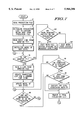
- FIG. 6 illustrates, in flow diagram form, a prediction generators according to one embodiment of the present invention.
- FIGS. 7 & 8 illustrate, in flow chart form, a correctness evaluator according to one embodiment of the present invention.
- the present invention provides an improved method and technique for verifying bus protocols in the design of integrated circuits.
- the following discussion details one embodiment of the present invention, which is illustrated in FIGS. 1-8, and is provided as an exemplar for clarity.
- the various methods discussed above may be implemented within dedicated hardware 15, or within processes implemented within a data processing system 13 as shown in FIG. 1.
- a typical hardware configuration of a workstation in accordance with the present invention is illustrated and includes a central processing unit (CPU)10, such as a conventional microprocessor, and a number of other units interconnected via system bus 12.
- the workstation shown in FIG. 1 includes random access memory (RAM) 14, read only memory (ROM) 16, and input/output (I/O) adapter 18 for connecting peripheral devices, such as disk units 20 and tape units 40, to bus 12.
- RAM random access memory
- ROM read only memory
- I/O input/output
- a user interface adapter 22 is used to connect a keyboard device 24 and a mouse 26 to the system bus 12.
- Other user interface devices such as
- a communications adapter 34 is also shown for connecting the workstation to a data processing network 17. Further, a display adapter 36 connects the system bus 12 to a display device 38.
- the method of the present invention may be implemented and stored in one or more of the disk units 20, tape drives 40, ROM 16 and/or RAM 14, or even made available to system 13 via a network connection through communications adapter 34 and thereafter processed by CPU 10. Because the apparatus implementing the present invention is, for the most part, composed of electronic components and circuits known to those skilled in the art, circuit details will not be explained in any greater extent than that considered necessary as illustrated above, for the understanding and appreciation of the underlying concepts of the present invention and in order not to obfuscate or distract from the teachings of the present invention.
- the integrated circuits being designed for element sizing are comprised of a plurality of elements (sometimes millions of elements) including transistors and logic gates. Each such transistor or gate has an inherent signal propagation delay time associated with it, and that delay is typically measured in nanoseconds. Timing constraints within integrated circuits are usually specified in nanoseconds and represent the maximum propagation time of a signal between two different points in an integrated circuit. Such timing constraints must be met in order for the integrated circuit to meet an overall specification relative to the speed with which signal processing must occur to provide a competitive product in the market place or to be compatible with other integrated circuits in a larger system.
- the speed of an integrated circuit is proportional to its size and its strength. For example, the size and strength of a transistor, is directly related to the width of a transistor gate for transistor elements.
- an initial design is chosen and while the number of elements, inputs and topology of the chip may remain the same, the sizes are modified for optimal size so that customer or user constraints are met but with a minimum of total chip size.
- the method may be used to verify protocol conformance to an electrical interface in a system, and is typically used during the design stage, but may also be useful for debug once a design has been realized.
- the present method implements a computer model of an electrical circuit to determine if the electrical interface of the circuit operates in conformity with a specified protocol. The results of this verification may result in a design change or may even result in a specification change.
- the electrical circuit computer model is to imitate the behavior of the circuit. Any number of types of information may be derived from the verification method, including information indicating the amount and degree of comprehension of test coverage.
- the electrical interface is a bus.
- a test file 40 is used to specify a number of agents that act upon the bus during the course of the test.
- Typical agents are bus masters (transaction initiators) with a list of transactions to perform, slaves (transaction responders) with different characteristics, and data initialization agents for slave memories. Specific agents will differ from one bus configuration to another.
- Agents are user defined, and may exist for any purpose the user finds convenient, such as an arbitration unit or central controller. For example, in one embodiment of the present invention, an agent is defined to apply all the precharge signals used on the buses when they are not being driven. Further, it is possible to define agents that have no direct effect on the bus.
- An initialization agent may be used to define common sub-routines.
- protocol templates 50 represents a group of protocol templates, containing protocol templates for the various agents that are defined in the system. From protocol templates 50 the template corresponding to the protocol associated with a single agent is instantiated for a given prediction.
- Test file 40 provides a test description and includes transactions involving a variety of agents. Test file 40 is based on an ordered list of instructions predetermined by the designer. Test file 40 provides information for a given agent that may be accessed by the corresponding protocol template of that agent is provided from protocol templates 50. Both the information from test file 40 and the template protocol from protocol templates 50 is provided to prediction generator 54.
- Test file 40 may implement any of a number of formats.
- Test information includes descriptions of each agent, where descriptions include, but are not limited to, such parameters as agent name, agent type, predecessors to the agent, and initialization information.
- the test file combines the agents and defines a series of events or transactions that will utilize the bus. In this way, the designer may verify conformity to the specified bus protocol and find bugs.
- the prediction generator 54 uses specific information about the performance of each agent and the information from test file 40 to predict what should occur on the bus.
- Prediction generator 54 Prediction generator 54, prediction file 56, and correctness evaluator 58 are all contained within unit 52.
- Prediction generator 54 reads information provided by test file 40 and in response outputs a prediction file specific to the test file information. This is done by instantiating the protocol templates for each of the bus agents (from protocol templates 50) with the test file 40 information, and composing a composite prediction graph.
- Prediction file 56 determines the expected results of running the transactions specified in test file 40.
- Prediction file 56 in turn becomes an input to correctness evaluator 58.
- Correctness evaluator 58 checks that there is a one-to-one mapping between transitions present in monitor output file 48 and prediction file 56 (i.e. that actual results match expected results).
- Stimulus providers 42 receive instructions in the form of information from test file 40.
- stimulus providers 42 provide the stimulus for the test to be performed by each agent.
- the stimulus provided by stimulus providers 42 is provided to the design simulation 44.
- Design simulation 44 runs a simulation of the design circuit in response to the stimulus provided.
- the form of stimulus depends on the type of design simulation 44 used.
- bus monitor 46 monitors signals on the bus in response to the stimulus providers.
- the output of the bus monitor 46 is provided to monitor file 48.
- Monitor file 48 stores information as it is received.
- the information in monitor file 48 is time stamped to indicate the time and sequence of events on the bus. Note that according to one embodiment of the present invention, the time stamp corresponds to a phase of the clock signal.
- Monitor file 48 includes a reset line which provides the initial state of all the signals provided in the monitor file. Each line in the monitor file contains a time stamp for each signal change, the name of each signal, and the updated value of the signal after the signal change. Monitor file 48 contains this information for each of the signals. This information will be used by correctness evaluator 58 to create a transition list.
- Monitor file 48 provides this information to correctness evaluator 58. Correctness evaluator 58 then compares the simulated output results from monitor file 48 with those of prediction file 56. Correctness evaluator 58 then makes a pass or fail determination based upon the match.
- Correctness evaluator 58 tests to a "clean bus model.”
- any non-predicted bus state is considered to be an error.
- Non-predicted bus states are often referred to as "spurious transitions", where a spurious signal changes state at some time other than that specified by the protocol. Noise may be considered a spurious transition, as may an unspecified signal.
- the clean bus model provides a stringent condition for checking conformance to the protocol. Acceptance criterion typically requires that all predicted to be driven according to the protocol specification must be actually driven. Further, acceptance criterion requires that no signal be driven at a time other than specified drive times. The latter criterion is more strict than is usually used by hardware designers, who tend to ignore signals driven at a time that is not sampled according to the protocol.
- Violation of the clean bus model may require the designer to use a guard condition or a qualification on such signals. If a qualification is implemented incorrectly, undesirable behavior could result. By alerting the designer to spurious transitions, the designer is made aware of potential hazards in the design. Note that a spurious or unexpected transition does not always cause a problem. In certain cases where no hardware is sampling the line at that time, there may be no problem, especially if all the data are getting through. However, any spurious transition constitutes a possible hazard in the design indicating that all the bus agents that sampled the signal are to be properly qualified so that they are not looking at that signal when they should not be. When a spurious transition occurs and it turns out to be harmless, it is often impractical to fix the design. In these situations, it is possible to alter the prediction template to allow specific spurious transitions without lessening the overall stringency of the test in any other area.
- prediction generator 54 operates on test file 40 and protocol template 50.
- Protocol template 50 is illustrated according to one embodiment of the present invention in FIG. 5.
- a prediction or protocol template is represented as a labeled directed graph in which each node specifies a condition to be evaluated. These conditions typically include partial bus states.
- Arcs specify timing constraints between pairs of nodes. For the present discussion the term "edge" is used to indicate an arc which carries ordering information. If there is no edge between two nodes then there is no explicit constraint between them.
- FIG. 3 illustrates a simple bus protocol involving a master and slave.
- the master is defined by two signals, a transaction start signal (TS), and an address (ADDRESS).
- the slave is defined by two signals, an address recognition signal (ADDR -- RECOG) and an address acknowledge (ADDR -- ACK).
- ADDR -- RECOG address recognition signal
- ADDR -- ACK address acknowledge
- CLOCK clock signal
- TS, ADDR -- RECOG, and ADDR -- ACK are active low signals.
- TS is asserted on a second CLOCK edge.
- ADDRESS is also driven on the second rising clock edge coincident with the assertion of TS.
- the slave's ADDR 13 RECOG is to be asserted one clock after assertion of the master's TS. Also, slave's ADDR -- ACK is to be asserted one clock after the master's TS.
- the behavior illustrated in FIG. 3 indicates the expected result on the bus.
- FIG. 4 illustrates the corresponding labeled directed graph defining the master and slave portions of the protocol illustrated in FIG. 3.
- a node in the graph is illustrated as a rectangular box or an oval, and each node corresponds to an event which may occur during the simulation.
- a node can be either required or optional.
- required nodes are illustrated as rectangular boxes, while optional nodes are illustrated as ovals. If the condition must eventually evaluate to true for the protocol to be correct, the node is required.
- a node When a node's condition evaluates to TRUE it is considered to have fired.
- a node may be tagged an AND node or an OR node. For clarity, an AND node is illustrated with a solid outline, while an OR node is illustrated with a dashed outline. With reference to an AND node, once the node is evaluated to true, all of its required successor will eventually fire, and as many of its optional successors as desired will also fire. In the case of an OR node, successors of an OR node are considered to be optional. An OR node will sequentially check successors until a first successor fires. At this point, it is not necessary to check the other successors. Successors of an OR node are put into a predetermined evaluation order. The evaluation order is specified by placing numeric tags on edges between OR node and its successors. The tag indicates the ordered position of each successor. Note that typically all successors to an OR are considered optional.
- Node 500 is a required, AND, sample node.
- a required node in a labeled directed graph, is one that must be satisfied. Alternate to a required node is an optional node which may be satisfied or may not.
- a drive node indicates that the condition defined in the node is to be driven on the bus. For clarity, drive nodes are illustrated with italicized text. Alternate to a drive node is a sample only node. For clarity, a sample only node is illustrated with plain text. Note that in one embodiment, a sample only node does not need to sample the bus.
- a directed arc connects node 500 to node 502, and indicates the processing flow. Node 502 is a required and drive node.
- the arc connecting node 500 to node 502 is labeled "1,X.”
- the label indicates a minimum, maximum timing constraint for satisfaction of the condition described by node 502 relative to when node 500 fired.
- the position to the left of the comma indicates the minimum timing constraint for node 502 with respect to node 500; for this arc the minimum timing constraint is 1.
- the position to the right indicates the maximum timing constraint for node 502 with respect to node 500, for this arc the maximum timing constraint is described by X, which is discussed below.
- the X of the label is the maximum timing constraint and indicates that there is no upper limit to the allowable delay after satisfaction of node 500 for TS assertion.
- Node 502 and node 504 also have a connecting arc which is labeled 0,0.
- node 502 has a connecting arc to node 506 labeled 1,1.
- the labels on the arc indicate minimum, maximum timing constraints after satisfaction of node 502 within which the connected node must be satisfied.
- the minimum, maximum timing constraints indicate that the ADDRESS signals are to be driven concurrently with the TS signal.
- the labeled directed graph of FIG. 4 is used to embody the protocol defined in FIG. 3.
- Node 508 is a required, AND, sample node which in this case is always validated as true.
- Node 508 is connected to node 510 by an arc labeled 0,X. This label indicates that the condition specified in node 510 may occur concurrently with the satisfaction of node 508 or any time thereafter.
- Node 510 is satisfied when TS is asserted and the ADDRESS signal is between an address minimum and an address maximum value.
- the minimum address value (ADDR -- MIN) together with the maximum address value (ADDR -- MAX) define the range of values for which the slave is programmed to respond.
- Node 510 is then connected to each of nodes 512 and 516 by arcs labeled 1,1.
- Node 512 represents the condition where the address recognition signal (ADDR -- RECOG) is asserted.
- Node 516 represents the condition where address acknowledge signal (ADDR -- ACK) is asserted.
- Each of nodes 512 and 516 are to be satisfied one clock cycle after TS is asserted.
- the protocol embodied in FIG. 4 is consistent with the time defined protocol of FIG. 3.
- Node 512 is then connected to node 514 by an arc labeled 1,1.
- Node 516 is connected to node 518 by an arc labeled 1,1.
- the labels on both of these arcs indicate that they are to occur one clock cycle after their predecessor node.
- the condition of node 514 requires that ADDR -- RECOG be negated. Note that ADDR -- RECOG must be asserted in node 512 prior to being negated in node 514 for node 514 to be satisfied.
- Node 514 is a successor to node 512, and node 512 is considered a predecessor to node 514.
- Node 518 represents the condition where ADDR -- ACK is negated. Again, the ADDR -- ACK negation of node 518 is only satisfied after ADDR -- ACK is asserted in node 516.
- the protocol illustrated in FIG. 4 is used to verify protocol conformity on the bus.
- the master is a first agent and the slave is a second agent.
- Each agent has a protocol that is specified for the bus.
- the protocol illustrated in FIG. 4 is not the only protocol associated with the agents, but is exemplary the translation from timing diagrams and constraints to a labeled directed graph embodiment of the protocol.
- FIG. 5 illustrates one embodiment of protocol template 50.
- FIG. 5 represents an agent that drives a bus signal, PIPEDEPTH, to count the number of transactions that are currently in progress on a pipelined bus.
- PIPEDEPTH bus signal
- Rectangular shaped nodes are "required” nodes.
- Oval nodes are "optional” nodes.
- Octagonal nodes provide the code associated with its connected node. Both required and optional nodes may be "AND” nodes, and are indicated by a single line outlining the node. Both required and optional nodes may be “OR” nodes, and are indicated by dashed lines outlining the node.
- a "drive” node is indicated by italicized text inside the node. If the text is not italicized the node is a “sample” node. Arrows directed from one node to another are called “arcs" and indicate the direction of processing flow. Comments are provided outside of some nodes to provide the reader with information for clarity and understanding. The convention provided in FIG. 5 is considered to be readily understandable to one of ordinary skill in the art, however alternate embodiments may be used to illustrate the labeled directed graph implementation.
- node 200 is a required, OR, drive node.
- Node 200 has two successors, node 202 and node 204.
- Node 202 is connected to node 200 by an arc labeled 0:3,X.
- Providing an evaluation order to successors of an OR node allows deterministic evaluation.
- the evaluation order is specified by putting numeric tags on the edges, with the lower numbered tags evaluated before the higher numbered tags.
- the tag in FIG. 5 is coupled with the label on the arc.
- node 202 is given an evaluation order of 0 and node 204 is given an evaluation order of 1.
- the evaluation order is the number to the left of the colon in the label attached to the arc.
- the number to the right of the colon indicates the minimum, maximum timing constraints, as described above.
- Node 200 is a drive node, meaning that the agent being simulated by node 200 is actually driving a signal on the bus.
- Node 200 is driving signal PIPEDEPTH.
- PIPEDEPTH is to be asserted at a time that is either the third or fourth phase of a four phased clock, as indicated by the number following the "@" symbol. Note that all of the signals considered herein, excepting PIPEDEPTH, are active low.
- PIPEDEPTH is a 2-bit counter. In this case, both successors of node 200, nodes 202 and 204, have a minimum timing constraint of 3 clocks with a maximum timing constraint that is unspecified.
- Node 204 represents a condition where a transaction is started on the bus. The transition start is indicated by assertion of the ADDR -- RECOG and ADDR -- ACK signals and the negation of the ABORT signal. Each of the conditions specified in node 204 is sampled at a third phase of the clock.
- Node 202 represents a condition where a transaction is ended on the bus. The transaction ending is indicated by the assertion of the TRANS -- END signal. According to this example, if a transaction is ended with the TRANS -- END signal assertion, as defined in node 202, prior to a transaction start, as defined in node 204, then the code associated with node 206 will be executed. Node 206 contains code to execute in case node 202 fires before node 204. According to one embodiment of the present invention, each node has the possibility of having code associated with it. Code is executed at the time its associated node is fired (i.e. evaluates to true). A typical purpose for implementing code execution is to latch bus signals at an early part of a transaction and then use the signals at a later part of the transaction.
- node 204 When node 204 fires prior to node 202, the condition represented by node 202 will no longer be evaluated. In this case, a transaction has started and the protocol will not continue to look for a transaction to end at node 204.
- node 202 and node 204 are optional, AND, sample nodes.
- Node 204 is connected to node 208 by an arc labeled 0,1. Note that there is no evaluation ordering given as node 204 is an AND node, indicating that all of its successors must evaluate to true. In this case, node 204 has a single successor node 208.
- Node 208 is a required, OR, drive node. 208 represents the condition where PIPEDEPTH is driven to 1.
- Node 208 has an arc directed to node 210 and an arc directed to node 212. Node 208 also has an arc connected from node 216 directed toward node 208.
- PIPEDEPTH indicates the number of transactions that are active on the bus. At node 208, PIPEDEPTH is driven to 1, indicating that a transaction has started as defined in node 204.
- Node 208 is an OR node where nodes 210 and node 212 are each assigned an evaluation order. Nodes 210 and 212 are sequentially evaluated according to the evaluation order until either one evaluates to true.
- Node 210 represents the condition of a second transaction start while the first transaction is active (i.e. before the first transaction ends, a second transaction starts).
- Node 210 is satisfied on ADDR -- RECOG assertion, ADDR -- ACK assertion, ABORT negation, and TRANS -- END negation. Note, to satisfy node 210, each of the four conditions must occur at a time that is at least 3 clock cycles after satisfaction of node 208. There is no maximum timing constraint on the conditions of node 210.
- Node 212 represents a condition where a first transaction has ended and no new transaction has started. Node 212 is satisfied on TRANS -- END assertion and either ADDR -- negation, ADDR -- ACK negation, or ABORT assertion. If a transaction ends and no new transaction is started, as defined in node 212, then the arc directed from node 212 to node 200 indicates a return to node 200. If a second transaction starts before the first transaction has ended, as indicated by node 210, then node 212 will no longer be evaluated. Node 210 is connected to node 214 by an arc labeled 0,1. Again, the label indicates a minimum, maximum timing constraint.
- Node 214 is a required, OR, drive node, where PIPEDEPTH is driven to a value of 2.
- Node 214 is connected to each of nodes 218 and 216 by directed arcs. Again, as node 214 is an OR node, nodes 218 and 216 are each given an evaluation order.
- Node 218 corresponds to an additional transaction start.
- Node 216 corresponds to a transaction end. If node 216 fires prior to node 218, process flow is directed back to node 208.
- the maximum depth for PIPEDEPTH is 2, as node 218 fires on the start of a new transaction and runs the code of node 220 in response.
- node 220 which contains the code associated with node 218.
- node 218 and node 220 are connected by a directed arc, without any label. Therefore, there are no constraints between firing of node 218 and execution of node 220. In other words, when node 218 is evaluated as TRUE, node 220 code is executed automatically.
- Prediction generator 54 receives information from test file 40 and protocol template 50 and creates a prediction file 56.
- FIG. 6 provides a flow chart describing the operation of prediction generator 54. The designer is able to select a test to perform, the test having an associated test file 40.
- process flow proceeds to block 600, which creates a global BEGIN node to serve as the entry point for prediction file 56.
- decision block 602 determines if there is any unprocessed agent, A, in test file 40.
- the agents included in test file 40 are selected as needed to perform the selected test.
- the agents included in test file 40 are listed in a processing order or evaluation order. If there is no unprocessed agent in test file 40, the process ends.
- test file 40 Each agent is defined by a template, where information is provided to prediction generator 54 regarding the agent.
- Information in test file 40 may include agent name, agent type, predecessors, and initialization code.
- an initialization node, I which incorporates the code necessary for initialization of agent, A.
- Initialization code is contained in test file 40 for agent, A.
- Initialization code typically specifies the characteristics of A assigning values to those variables needed by prediction generator 54 to implement agent, A in a labeled directed graph.
- the variables for A the bus master, contain information to specify a set of transactions that A will initiate, possibly including timing information.
- END nodes of predecessors to agent, A are connected to initialization node, I.
- the labeled directed graph generated by prediction generator is pieced together from the test file 40 information defining each agent.
- a BEGIN node is specified for each agent in a labeled directed graph.
- the BEGIN node serves as the entry point for the graph. Refer to blocks 500 and 508 of FIG. 4.
- Each agent type that that is a potential predecessor for another agent will also have an END node specified.
- arcs are placed from the END node of a predecessor agent to the initialization node of a successor agent according to predecessor information in test file 40. In other words, the information regarding agent, A, will include a list of A's predecessors.
- prediction generator 54 places arcs from the END node of agents on the list to the initialization node of agent, A.
- END nodes of A's predecessors are connected to the initialization node, I, for this agent.
- the initialization node subsequently has an arc placed between it and the BEGIN node of its agent.
- Step 608 positions agent, A, in the labeled directed graph.
- Process flow continues to block 610, where a template file for A is opened in the protocol templates file 50.
- the template file is determined by the agent type information in test file 40 for agent, A.
- Process flow then continues to decision block 612 to determine if there is an unread node, N, in the protocol template file.
- N an unread node
- process flow will continue to decision block 602 to process a next unprocessed agent.
- the process continues for all the nodes of all the agents.
- the same protocol template file may be processed more than once if ore than one agent are defined in test file 40 with the same agent type.
- Note some protocol template file may be processed more than once if there are more than one agent defined in If there is an unread node in the protocol template file, process flow continues to block 614 to read N from the protocol template file.
- the names of N and N's predecessor references are renamed to include A's name by embedding.
- Process flow then continues to decision block 618 which checks to see if N is the BEGIN node for this agent. If it is not, then process control continues to block 622. If N is the BEGIN node then the initialization node I is added to the predecessor list of N. Finally, at block 622 predictor generator 54 outputs a renamed version of node N. Process flow then returns to decision block 612.
- the significance of renaming nodes is to distinguish a specific agent from other similar agents. For example, any bus master that is to have a protocol as defined in FIG. 3 will have the same nodes as described in FIG. 4. As each new agent in the system is processed by prediction generator 54, there is a label attached which distinguishes that agent.
- FIGS. 7 and 8 illustrate a flow diagram describing operations of a correctness evaluator 58 from FIG. 2, according to one embodiment of the present invention. It is first necessary to define what conditions constitute a correct simulation. According to the present embodiment, the correctness criterion is stringent as it uses the clean bus model. A correct implementation of a protocol is defined as one in which all required nodes fire within the imposed timing constraints of their incoming edges and no bus signals change state unless there is a drive node corresponding to such a state change.
- monitor file 48 contains a distinguished "reset" line that specifies the initial state of all the signals comprising the bus.
- Each subsequent line in monitor file 48 contains a time stamp and a list of pairs, where the first element in each pair is the name of a given bus signal and the second element is a new value of the given bus signal at the time of the time stamp.
- Correctness evaluator 58 initializes its own internal model of the state of the bus according to values specified in the reset line of monitor file 48.
- correctness evaluator 58 reads prediction file 56 at block 72.
- Prediction generator 54 creates prediction file 56 from the information in test file 40 and protocol templates 50.
- Flow continues then to block 74 where correctness evaluator 58 initializes an evaluation list to contain the global BEGIN node from prediction file 56.
- prediction file 56 contains a global BEGIN node which specifies the entry point to the chart.
- the reset line is read from monitor file 48.
- Correctness evaluator 58 has a model of the bus and an internal model of the bus state. Process flow then continues to block 80, where the internal model is initialized.
- process flow continues to decision box 78, where correctness evaluator 58 determines if monitor file 48 is empty. If monitor file 48 is not empty, then correctness evaluator 58 reads a line from monitor file 48 at block 82. Correctness evaluator 58 then creates a transition list for a current time stamp, which is specified in the line read from monitor file 48. Process flow continues to block 86, where the transition list is created. At block 84, the model of the bus state is updated according to the information read from the line of monitor file 48. A line of monitor file 48 contains information at a given timestamp for every signal described in test file 40.
- Process flow then continues to decision block 88 to determine if there is an unevaluated entry in the evaluation list. If there is an unevaluated entry, E1, then decision block 90 determines if the condition of E1 evaluates to TRUE. If the condition of E1 does not evaluate to true, process flow returns to decision block 88. If the condition of E1 does evaluate to true, then process flow continues to decision block 92 to determine if E1 has code associated with it. If E1 has code, the code is executed in block 94. If E1 has no associated code, process flow continues to box 96. Additionally, once the code associated with E1 is executed, process flow continues to block 96. At block 96, E1 is removed from the evaluation list.
- Process flow continues to decision block 98, where it is determined if E1 is a successor of an OR node. If E1 is a successor to an OR node, then the siblings of E1 are removed from the evaluation list at block 100. According to one embodiment of the present invention, when an OR node fires, all of its successors are placed in the evaluation list for further evaluation, but as soon the first of these successors fires, all of its siblings are removed from the evaluation list. Note that in one embodiment of the present invention, all successors of an OR node are considered optional. Additionally, all successors of an OR node are added to the evaluation list regardless of whether all the predecessors have been fired. If E1 is not a successor of an OR node, process flow continues to decision box 101.
- E1 is the successor of an OR node and the siblings are removed from the evaluation list at block 100, then process flow continues to decision block 101.
- decision block 101 it is determined if E1 is a drive node. If E1 is not a drive node, then process flow continues to decision block 106. If E1 is a drive node, process flow continues to decision block 102 to determine if there is a signal transition, T, in the transition list corresponding to the condition of E1. If there is no signal transition, T, then process flow continues to decision block 106. However, if there is a signal transition T, then T is removed from the transition list in block 104 and process flow continues to block 106.
- decision block 106 it is determined if there is an unprocessed successor, E2, to E1 that has not been processed since E1 was fired. If there is such an E2, then decision block 108 determines if E2 has any unfired predecessors that are not optional nodes. If there are no unprocessed successors to E1, then process flow returns to decision block 88. As discussed previously, successors of an OR node are added to an evaluation list regardless of whether predecessors have fired. If there are no unfired non-optional predecessors, then E2 is added to the evaluation list in block 110. If there are unfired non-optional predecessors, process flow returns to decision block 106 to determine if there are other unprocessed successors to E1. If E2 has no unfired non-optional predecessors, then E2 is added to the evaluation list in block 110 and process flow returns to decision block 106. When all successors to E1 have been processed, control flow returns from decision block 106 to decision block 88.
- process flow continues to decision block 112 to determine if there is an expired entry, E3, in the evaluation list. If there are no expired entries then process flow continues to decision block 118. If there is an expired entry, decision block 114 determines if it is optional. If E3 is not optional, correction evaluator 58 will exit with a FAIL status at block 116. An exit at this point indicates a failure of a required condition. If E3 is optional, process flow continues to decision box 118 to determine if the transition list is empty. If the transition list is empty at decision block 118, process flow returns to block 78.
- transition list is not empty at decision block 118, then process flow continues to block 120, where correction evaluator 58 exits with FAIL status. An exit at this point indicates a spurious transition, i.e. an unspecified state or transition occurred on the bus.
- process flow continues to decision block 130 to determine if there are required entries on the evaluation list. If there are such entries, correction evaluator 58 will exit with a FAIL status at block 132. An exit at this point indicates a failure of a required condition. Returning to decision block 130 if there are no required entries on the evaluation list, correction evaluator 58 will exit with a PASS status at block 134.
- the present invention offers a method for verifying bus protocols which uses a strict condition for checking conformance to the protocol.
- the method provides that all signals predicted to be driven according to the protocol specification are driven and that no signals are driven at a time when they are not specified to be driven.
- the present invention offers a method of recognizing when a guard condition or qualification is needed for the signals available on the bus. This feature offers circuit designers a method to detect potential hazards in their design.
- the present invention offers a method of storing state and timing history information, adding valuable information for debug and analysis. By storing status information about the electrical interface and information about when transactions start, the circuit designer is provided a flexible verification tool.
- the present invention allows for protocol coverage analysis computation automatically and insures that the test plan has covered all the relevant aspects of the protocol. Additionally, the present invention offers a flexible method to separate protocol-defined timing and constraints from implementation-dependent timing constraints. This is advantageous as the amount of delay incurred by access to an external memory device is often variable.
- the present invention offers a modular method of protocol specification. Protocol templates for different types of agents are used to specify the conditions of any number of that type of agent in the system.
- the present invention offers a method of detecting noise on the bus which occurs at times other than when the protocol says the signals are to be sampled. This allows detection of possible hardware hazards based solely on improperly driven signals. According to one embodiment of the present invention, optional transitions are handled in a consistent manner.
- prediction file 56 could also be a general test file.
- An advantage of the present invention is that it allows input from a test program to tailor bus signal change predictions and verify that the test program performs as it is programmed to perform.
- the present invention allows designers to create flexible test programs and behavior models which target the creation of specific bus conditions.
Landscapes
- Engineering & Computer Science (AREA)
- General Engineering & Computer Science (AREA)
- Theoretical Computer Science (AREA)
- Computer Hardware Design (AREA)
- Quality & Reliability (AREA)
- Physics & Mathematics (AREA)
- General Physics & Mathematics (AREA)
- Computer Networks & Wireless Communication (AREA)
- Signal Processing (AREA)
- Debugging And Monitoring (AREA)
Abstract
Description
Claims (23)
Priority Applications (1)
| Application Number | Priority Date | Filing Date | Title |
|---|---|---|---|
| US08/888,588 US5966306A (en) | 1997-07-07 | 1997-07-07 | Method for verifying protocol conformance of an electrical interface |
Applications Claiming Priority (1)
| Application Number | Priority Date | Filing Date | Title |
|---|---|---|---|
| US08/888,588 US5966306A (en) | 1997-07-07 | 1997-07-07 | Method for verifying protocol conformance of an electrical interface |
Publications (1)
| Publication Number | Publication Date |
|---|---|
| US5966306A true US5966306A (en) | 1999-10-12 |
Family
ID=25393481
Family Applications (1)
| Application Number | Title | Priority Date | Filing Date |
|---|---|---|---|
| US08/888,588 Expired - Lifetime US5966306A (en) | 1997-07-07 | 1997-07-07 | Method for verifying protocol conformance of an electrical interface |
Country Status (1)
| Country | Link |
|---|---|
| US (1) | US5966306A (en) |
Cited By (18)
| Publication number | Priority date | Publication date | Assignee | Title |
|---|---|---|---|---|
| US6106567A (en) * | 1998-04-28 | 2000-08-22 | Motorola Inc. | Circuit design verification tool and method therefor using maxwell's equations |
| US6175925B1 (en) | 1996-06-13 | 2001-01-16 | Intel Corporation | Tamper resistant player for scrambled contents |
| US6178509B1 (en) | 1996-06-13 | 2001-01-23 | Intel Corporation | Tamper resistant methods and apparatus |
| US6205550B1 (en) * | 1996-06-13 | 2001-03-20 | Intel Corporation | Tamper resistant methods and apparatus |
| US6311296B1 (en) * | 1998-12-29 | 2001-10-30 | Intel Corporation | Bus management card for use in a system for bus monitoring |
| US6442514B1 (en) * | 1998-12-04 | 2002-08-27 | Xilinx, Inc. | Method and system for simulating a communications bus |
| US20030070030A1 (en) * | 2001-10-04 | 2003-04-10 | Smith Brian E. | Automatic corner case search in multi-agent bus interface verification |
| US6571204B1 (en) * | 1998-08-04 | 2003-05-27 | Micron Technology, Inc. | Bus modeling language generator |
| US20030233395A1 (en) * | 2002-06-17 | 2003-12-18 | Cherian Sanjay John | Conformance testing without reference implementation of an XML standard |
| US20040044508A1 (en) * | 2002-08-29 | 2004-03-04 | Hoffman Robert R. | Method for generating commands for testing hardware device models |
| US6915248B1 (en) * | 1999-06-28 | 2005-07-05 | Cadence Design Systems, Inc. | Method and apparatus for transforming test stimulus |
| US20060107120A1 (en) * | 2001-03-28 | 2006-05-18 | Intel Corporation | Microprocessor design support for computer system and platform validation |
| US20060156269A1 (en) * | 2005-01-07 | 2006-07-13 | Micron Technology, Inc. | Selecting data to verify in hardware device model simulation test generation |
| US20060230364A1 (en) * | 2002-04-25 | 2006-10-12 | Lyubov Zhivova | Method and computer program product for generation of bus functional models |
| US20100299440A1 (en) * | 2003-10-17 | 2010-11-25 | Meyer James W | Method and apparatus for sending data from multiple sources over a communications bus |
| US20160283299A1 (en) * | 2015-03-24 | 2016-09-29 | Honeywell International Inc. | Apparatus and method for fault detection to ensure device independence on a bus |
| US10169710B2 (en) * | 2015-03-24 | 2019-01-01 | International Business Machines Corporation | Automated decision support provenance and simulation |
| CN117459276A (en) * | 2023-10-26 | 2024-01-26 | 齐鲁中科新动能创新研究院 | Debugging device applied to master-slave communication system |
Citations (10)
| Publication number | Priority date | Publication date | Assignee | Title |
|---|---|---|---|---|
| US4764862A (en) * | 1984-06-21 | 1988-08-16 | Honeywell Bull Inc. | Resilient bus system |
| US4825438A (en) * | 1982-03-08 | 1989-04-25 | Unisys Corporation | Bus error detection employing parity verification |
| US5440697A (en) * | 1991-10-23 | 1995-08-08 | International Business Machines Corporation | Method and apparatus for simulating I/O devices |
| US5455911A (en) * | 1993-04-05 | 1995-10-03 | Allen-Bradley Company, Inc. | Communications protocol for use in transferring data over a serial bus |
| US5566347A (en) * | 1992-09-24 | 1996-10-15 | Conner Peripherals, Inc. | Multiple interface driver circuit for a peripheral storage device |
| US5590355A (en) * | 1993-08-11 | 1996-12-31 | Sharp Kabushiki Kaisha | Data driven processor, a data driven information processing device, and a method of verifying path connections of a plurality of data driven processors in such a data driven information processing device |
| US5623499A (en) * | 1994-06-27 | 1997-04-22 | Lucent Technologies Inc. | Method and apparatus for generating conformance test data sequences |
| US5663076A (en) * | 1995-08-08 | 1997-09-02 | Lsi Logic Corporation | Automating photolithography in the fabrication of integrated circuits |
| US5699350A (en) * | 1995-10-06 | 1997-12-16 | Canon Kabushiki Kaisha | Reconfiguration of protocol stacks and/or frame type assignments in a network interface device |
| US5758101A (en) * | 1995-07-14 | 1998-05-26 | Alliance Peripheral Systems, Inc. | Method and apparatus for connecting and disconnecting peripheral devices to a powered bus |
-
1997
- 1997-07-07 US US08/888,588 patent/US5966306A/en not_active Expired - Lifetime
Patent Citations (10)
| Publication number | Priority date | Publication date | Assignee | Title |
|---|---|---|---|---|
| US4825438A (en) * | 1982-03-08 | 1989-04-25 | Unisys Corporation | Bus error detection employing parity verification |
| US4764862A (en) * | 1984-06-21 | 1988-08-16 | Honeywell Bull Inc. | Resilient bus system |
| US5440697A (en) * | 1991-10-23 | 1995-08-08 | International Business Machines Corporation | Method and apparatus for simulating I/O devices |
| US5566347A (en) * | 1992-09-24 | 1996-10-15 | Conner Peripherals, Inc. | Multiple interface driver circuit for a peripheral storage device |
| US5455911A (en) * | 1993-04-05 | 1995-10-03 | Allen-Bradley Company, Inc. | Communications protocol for use in transferring data over a serial bus |
| US5590355A (en) * | 1993-08-11 | 1996-12-31 | Sharp Kabushiki Kaisha | Data driven processor, a data driven information processing device, and a method of verifying path connections of a plurality of data driven processors in such a data driven information processing device |
| US5623499A (en) * | 1994-06-27 | 1997-04-22 | Lucent Technologies Inc. | Method and apparatus for generating conformance test data sequences |
| US5758101A (en) * | 1995-07-14 | 1998-05-26 | Alliance Peripheral Systems, Inc. | Method and apparatus for connecting and disconnecting peripheral devices to a powered bus |
| US5663076A (en) * | 1995-08-08 | 1997-09-02 | Lsi Logic Corporation | Automating photolithography in the fabrication of integrated circuits |
| US5699350A (en) * | 1995-10-06 | 1997-12-16 | Canon Kabushiki Kaisha | Reconfiguration of protocol stacks and/or frame type assignments in a network interface device |
Non-Patent Citations (6)
| Title |
|---|
| Gerald J. Holzmann, "Design and Validation of Computer Protocols," Synopsis, Prentice Hall, 1991, Chapter listing only, full book available to "Researchers and professionals". |
| Gerald J. Holzmann, Design and Validation of Computer Protocols, Synopsis, Prentice Hall, 1991, Chapter listing only, full book available to Researchers and professionals . * |
| Gerard J. Holzmann, "Basic Spin Manual," Bell Laboratories, Murray Hill, NJ 07974, pp. 1-32. |
| Gerard J. Holzmann, Basic Spin Manual, Bell Laboratories, Murray Hill, NJ 07974, pp. 1 32. * |
| Oded Maler, Sergio Yovine, "Hardware Timing Verification Using KRONOS," Spectre-Verimag, Miniparc-zirst, 38330 Montbonnot, France, pp. 1-8. |
| Oded Maler, Sergio Yovine, Hardware Timing Verification Using KRONOS, Spectre Verimag, Miniparc zirst, 38330 Montbonnot, France, pp. 1 8. * |
Cited By (29)
| Publication number | Priority date | Publication date | Assignee | Title |
|---|---|---|---|---|
| US6175925B1 (en) | 1996-06-13 | 2001-01-16 | Intel Corporation | Tamper resistant player for scrambled contents |
| US6178509B1 (en) | 1996-06-13 | 2001-01-23 | Intel Corporation | Tamper resistant methods and apparatus |
| US6205550B1 (en) * | 1996-06-13 | 2001-03-20 | Intel Corporation | Tamper resistant methods and apparatus |
| US6106567A (en) * | 1998-04-28 | 2000-08-22 | Motorola Inc. | Circuit design verification tool and method therefor using maxwell's equations |
| US6571204B1 (en) * | 1998-08-04 | 2003-05-27 | Micron Technology, Inc. | Bus modeling language generator |
| US6442514B1 (en) * | 1998-12-04 | 2002-08-27 | Xilinx, Inc. | Method and system for simulating a communications bus |
| US6311296B1 (en) * | 1998-12-29 | 2001-10-30 | Intel Corporation | Bus management card for use in a system for bus monitoring |
| US6915248B1 (en) * | 1999-06-28 | 2005-07-05 | Cadence Design Systems, Inc. | Method and apparatus for transforming test stimulus |
| US20060107120A1 (en) * | 2001-03-28 | 2006-05-18 | Intel Corporation | Microprocessor design support for computer system and platform validation |
| US7487398B2 (en) * | 2001-03-28 | 2009-02-03 | Intel Corporation | Microprocessor design support for computer system and platform validation |
| US20030070030A1 (en) * | 2001-10-04 | 2003-04-10 | Smith Brian E. | Automatic corner case search in multi-agent bus interface verification |
| US6842819B2 (en) * | 2001-10-04 | 2005-01-11 | Sun Microsystems, Inc. | Automatic corner case search in multi-agent bus interface verification |
| US20060230364A1 (en) * | 2002-04-25 | 2006-10-12 | Lyubov Zhivova | Method and computer program product for generation of bus functional models |
| US7634396B2 (en) | 2002-04-25 | 2009-12-15 | Freescale Semiconductor, Inc. | Method and computer program product for generation of bus functional models |
| US8214421B2 (en) | 2002-06-17 | 2012-07-03 | Ibm International Group Bv | Conformance testing without reference implementation of an XML standard |
| US20030233395A1 (en) * | 2002-06-17 | 2003-12-18 | Cherian Sanjay John | Conformance testing without reference implementation of an XML standard |
| US20040044508A1 (en) * | 2002-08-29 | 2004-03-04 | Hoffman Robert R. | Method for generating commands for testing hardware device models |
| US20060271347A1 (en) * | 2002-08-29 | 2006-11-30 | Micron Technology, Inc. | Method for generating commands for testing hardware device models |
| US8806152B2 (en) | 2003-10-17 | 2014-08-12 | Micron Technology, Inc. | Method and apparatus for sending data from multiple sources over a communications bus |
| US9652412B2 (en) | 2003-10-17 | 2017-05-16 | Micron Technology, Inc. | Method and apparatus for sending data from multiple sources over a communications bus |
| US20100299440A1 (en) * | 2003-10-17 | 2010-11-25 | Meyer James W | Method and apparatus for sending data from multiple sources over a communications bus |
| US8327089B2 (en) | 2003-10-17 | 2012-12-04 | Micron Technology, Inc. | Method and apparatus for sending data from multiple sources over a communications bus |
| US8095748B2 (en) | 2003-10-17 | 2012-01-10 | Micron Technology, Inc. | Method and apparatus for sending data from multiple sources over a communications bus |
| US7778812B2 (en) * | 2005-01-07 | 2010-08-17 | Micron Technology, Inc. | Selecting data to verify in hardware device model simulation test generation |
| US20060156269A1 (en) * | 2005-01-07 | 2006-07-13 | Micron Technology, Inc. | Selecting data to verify in hardware device model simulation test generation |
| US20160283299A1 (en) * | 2015-03-24 | 2016-09-29 | Honeywell International Inc. | Apparatus and method for fault detection to ensure device independence on a bus |
| US9934117B2 (en) * | 2015-03-24 | 2018-04-03 | Honeywell International Inc. | Apparatus and method for fault detection to ensure device independence on a bus |
| US10169710B2 (en) * | 2015-03-24 | 2019-01-01 | International Business Machines Corporation | Automated decision support provenance and simulation |
| CN117459276A (en) * | 2023-10-26 | 2024-01-26 | 齐鲁中科新动能创新研究院 | Debugging device applied to master-slave communication system |
Similar Documents
| Publication | Publication Date | Title |
|---|---|---|
| US5966306A (en) | Method for verifying protocol conformance of an electrical interface | |
| US6651228B1 (en) | Intent-driven functional verification of digital designs | |
| Cerny et al. | SVA: the power of assertions in systemVerilog | |
| US6083269A (en) | Digital integrated circuit design system and methodology with hardware | |
| US6199031B1 (en) | HDL simulation interface for testing and verifying an ASIC model | |
| US8326592B2 (en) | Method and system for verifying electronic designs having software components | |
| US8418093B2 (en) | Method and system for design simplification through implication-based analysis | |
| US7587690B1 (en) | Method and system for global coverage analysis | |
| US7640476B2 (en) | Method and system for automated path delay test vector generation from functional tests | |
| US6954915B2 (en) | System and methods for pre-artwork signal-timing verification of an integrated circuit design | |
| US20030018461A1 (en) | Simulation monitors based on temporal formulas | |
| US6493852B1 (en) | Modeling and verifying the intended flow of logical signals in a hardware design | |
| US6539523B1 (en) | Automatic formulation of design verification checks based upon a language representation of a hardware design to verify the intended behavior of the hardware design | |
| US9721058B2 (en) | System and method for reactive initialization based formal verification of electronic logic design | |
| US6571375B1 (en) | Determining dependency relationships among design verification checks | |
| Simpson | FPGA design | |
| CN113282492A (en) | Operating system kernel formal verification method | |
| Bombieri et al. | Incremental ABV for functional validation of TL-to-RTL design refinement | |
| US7606694B1 (en) | Framework for cycle accurate simulation | |
| US6968520B2 (en) | System verifying apparatus and method which compares simulation result based on a random test program and a function simulation | |
| US11295051B2 (en) | System and method for interactively controlling the course of a functional simulation | |
| Kaja et al. | Modelling Peripheral Designs using FSM-like Notation for Complete Property Set Generation | |
| US10635766B2 (en) | Simulation employing level-dependent multitype events | |
| US7634396B2 (en) | Method and computer program product for generation of bus functional models | |
| Ecker et al. | Requirements and concepts for transaction level assertion refinement |
Legal Events
| Date | Code | Title | Description |
|---|---|---|---|
| AS | Assignment |
Owner name: MOTOROLA, INC., ILLINOIS Free format text: ASSIGNMENT OF ASSIGNORS INTEREST;ASSIGNORS:NODINE, MARK H.;MARTIN, HAROLD M.;NGUYEN, ANHTU;REEL/FRAME:008674/0881 Effective date: 19970626 |
|
| STCF | Information on status: patent grant |
Free format text: PATENTED CASE |
|
| FPAY | Fee payment |
Year of fee payment: 4 |
|
| AS | Assignment |
Owner name: FREESCALE SEMICONDUCTOR, INC., TEXAS Free format text: ASSIGNMENT OF ASSIGNORS INTEREST;ASSIGNOR:MOTOROLA, INC.;REEL/FRAME:015698/0657 Effective date: 20040404 Owner name: FREESCALE SEMICONDUCTOR, INC.,TEXAS Free format text: ASSIGNMENT OF ASSIGNORS INTEREST;ASSIGNOR:MOTOROLA, INC.;REEL/FRAME:015698/0657 Effective date: 20040404 |
|
| AS | Assignment |
Owner name: CITIBANK, N.A. AS COLLATERAL AGENT, NEW YORK Free format text: SECURITY AGREEMENT;ASSIGNORS:FREESCALE SEMICONDUCTOR, INC.;FREESCALE ACQUISITION CORPORATION;FREESCALE ACQUISITION HOLDINGS CORP.;AND OTHERS;REEL/FRAME:018855/0129 Effective date: 20061201 Owner name: CITIBANK, N.A. AS COLLATERAL AGENT,NEW YORK Free format text: SECURITY AGREEMENT;ASSIGNORS:FREESCALE SEMICONDUCTOR, INC.;FREESCALE ACQUISITION CORPORATION;FREESCALE ACQUISITION HOLDINGS CORP.;AND OTHERS;REEL/FRAME:018855/0129 Effective date: 20061201 |
|
| FPAY | Fee payment |
Year of fee payment: 8 |
|
| AS | Assignment |
Owner name: CITIBANK, N.A., AS COLLATERAL AGENT,NEW YORK Free format text: SECURITY AGREEMENT;ASSIGNOR:FREESCALE SEMICONDUCTOR, INC.;REEL/FRAME:024397/0001 Effective date: 20100413 Owner name: CITIBANK, N.A., AS COLLATERAL AGENT, NEW YORK Free format text: SECURITY AGREEMENT;ASSIGNOR:FREESCALE SEMICONDUCTOR, INC.;REEL/FRAME:024397/0001 Effective date: 20100413 |
|
| FPAY | Fee payment |
Year of fee payment: 12 |
|
| AS | Assignment |
Owner name: ZOZO MANAGEMENT, LLC, DELAWARE Free format text: ASSIGNMENT OF ASSIGNORS INTEREST;ASSIGNOR:FREESCALE SEMICONDUCTOR, INC.;REEL/FRAME:034038/0946 Effective date: 20120629 |
|
| AS | Assignment |
Owner name: APPLE INC., CALIFORNIA Free format text: ASSIGNMENT OF ASSIGNORS INTEREST;ASSIGNOR:ZOZO MANAGEMENT, LLC;REEL/FRAME:034732/0019 Effective date: 20141219 |
|
| AS | Assignment |
Owner name: FREESCALE SEMICONDUCTOR, INC., TEXAS Free format text: PATENT RELEASE;ASSIGNOR:CITIBANK, N.A., AS COLLATERAL AGENT;REEL/FRAME:037356/0553 Effective date: 20151207 Owner name: FREESCALE SEMICONDUCTOR, INC., TEXAS Free format text: PATENT RELEASE;ASSIGNOR:CITIBANK, N.A., AS COLLATERAL AGENT;REEL/FRAME:037354/0225 Effective date: 20151207 Owner name: FREESCALE SEMICONDUCTOR, INC., TEXAS Free format text: PATENT RELEASE;ASSIGNOR:CITIBANK, N.A., AS COLLATERAL AGENT;REEL/FRAME:037356/0143 Effective date: 20151207 |