US5540037A - Control system for electric drive riding mower - Google Patents
Control system for electric drive riding mower Download PDFInfo
- Publication number
- US5540037A US5540037A US08/418,936 US41893695A US5540037A US 5540037 A US5540037 A US 5540037A US 41893695 A US41893695 A US 41893695A US 5540037 A US5540037 A US 5540037A
- Authority
- US
- United States
- Prior art keywords
- mower
- reel
- gang mower
- control circuit
- gang
- Prior art date
- Legal status (The legal status is an assumption and is not a legal conclusion. Google has not performed a legal analysis and makes no representation as to the accuracy of the status listed.)
- Expired - Lifetime
Links
Images
Classifications
-
- A—HUMAN NECESSITIES
- A01—AGRICULTURE; FORESTRY; ANIMAL HUSBANDRY; HUNTING; TRAPPING; FISHING
- A01D—HARVESTING; MOWING
- A01D69/00—Driving mechanisms or parts thereof for harvesters or mowers
- A01D69/02—Driving mechanisms or parts thereof for harvesters or mowers electric
-
- A—HUMAN NECESSITIES
- A01—AGRICULTURE; FORESTRY; ANIMAL HUSBANDRY; HUNTING; TRAPPING; FISHING
- A01D—HARVESTING; MOWING
- A01D34/00—Mowers; Mowing apparatus of harvesters
- A01D34/01—Mowers; Mowing apparatus of harvesters characterised by features relating to the type of cutting apparatus
- A01D34/412—Mowers; Mowing apparatus of harvesters characterised by features relating to the type of cutting apparatus having rotating cutters
- A01D34/42—Mowers; Mowing apparatus of harvesters characterised by features relating to the type of cutting apparatus having rotating cutters having cutters rotating about a horizontal axis, e.g. cutting-cylinders
- A01D34/43—Mowers; Mowing apparatus of harvesters characterised by features relating to the type of cutting apparatus having rotating cutters having cutters rotating about a horizontal axis, e.g. cutting-cylinders mounted on a vehicle, e.g. a tractor, or drawn by an animal or a vehicle
- A01D34/44—Mowers; Mowing apparatus of harvesters characterised by features relating to the type of cutting apparatus having rotating cutters having cutters rotating about a horizontal axis, e.g. cutting-cylinders mounted on a vehicle, e.g. a tractor, or drawn by an animal or a vehicle with two or more cutters
-
- A—HUMAN NECESSITIES
- A01—AGRICULTURE; FORESTRY; ANIMAL HUSBANDRY; HUNTING; TRAPPING; FISHING
- A01D—HARVESTING; MOWING
- A01D34/00—Mowers; Mowing apparatus of harvesters
- A01D34/01—Mowers; Mowing apparatus of harvesters characterised by features relating to the type of cutting apparatus
- A01D34/412—Mowers; Mowing apparatus of harvesters characterised by features relating to the type of cutting apparatus having rotating cutters
- A01D34/42—Mowers; Mowing apparatus of harvesters characterised by features relating to the type of cutting apparatus having rotating cutters having cutters rotating about a horizontal axis, e.g. cutting-cylinders
- A01D34/56—Driving mechanisms for the cutters
- A01D34/58—Driving mechanisms for the cutters electric
-
- A—HUMAN NECESSITIES
- A01—AGRICULTURE; FORESTRY; ANIMAL HUSBANDRY; HUNTING; TRAPPING; FISHING
- A01D—HARVESTING; MOWING
- A01D75/00—Accessories for harvesters or mowers
- A01D75/30—Arrangements for trailing two or more mowers
Definitions
- the present invention relates generally to turf care equipment, and more particularly, to an all electric operation riding greens mower.
- a number of greens mowers are known in the art and are discussed in U.S. Pat. Nos. 3,425,197; 3,429,110; and 4,021,996.
- a more specific type of greens mower, a riding greens mower with multiple or gang cutting units is the subject of and discussed in U.S. Pat. Nos. 3,511,033; 3,668,844; 4,866,917; and 5,042,236.
- Common among the mowers discussed in these patents is the reliance on an internal combustion engine as a source of power, and complex drive mechanisms or hydrostatic systems for supplying power to the ground engaging wheels and the reel mowing units. These machines suffer a number of disadvantages.
- the present invention provides an all electric drive riding greens mower.
- the mower includes a frame member which is supported for movement upon a plurality of ground engaging wheels and upon which are supported a battery power source, an operator station and a plurality of reel lawn mowers.
- An electric motor provides driving torque for motivating the mower between and over golf course greens or other surfaces to be mowed, and individual electric motors provide driving torque for each of the reel lawn mowers.
- Electrically driven linear actuators are also provided and facilitate moving the reel lawn mowers between a lowered operating position in which the reel lawn mowers engage the turf being mowed and a raised non-operating or transport position.
- the unique frame member provides a pivoting mount for at least one of the reel mowers to facilitate service and is further ergonomically constructed to facilitate efficient operator utilization of the mower.
- the frame member is further efficiently utilized to support and protect various electrical and mechanical components.
- Operator orientated controls layout and an operator communication panel facilitate efficient utilization of the mower. All electric operation provides for an emissionless riding greens mower which is extremely quiet in operation. Electric operation of the reel lawn mowers further provides a convenient means for on unit backlapping as well as for operator customized mower control.
- the unique and efficient frame construction of the riding greens mower of the present invention provides the rigid structure required for such a mower.
- Most of the frame members are multi-purpose.
- the battery power source, the reel mower mounting structure, the drive axle and electric motor mounting structure, the seat support structure, the foot deck structure and other portions of the frame assembly serve multiple purposes in a highly efficient design.
- the frame is designed with an outer periphery tubular structure interlinked with support members. Therefore, a rigid structure can be provided without substantial use of gussets or other reinforcements.
- This frame design further provides for a riding greens mower which is light in weight. Each of these considerations are highly important for preventing soil compaction, which can damage a green, due to the weight of mower.
- the greens mower of the present invention is laid out in a three wheel design with two wheels mounted towards the front of the unit on a common drive axle. This arrangement facilitates driving both of these wheels from a single electric motor, again reducing the weight of the unit.
- the mower has an elongated frame structure which, while enhancing the stability of the mower, provides for positioning the battery power source behind and under the operator.
- the third wheel is positioned at the rear of the mower on a pivoting mount for steering the vehicle.
- the wide spacing of the front ground engaging wheels allows for maintaining the track of the rear wheel within the track of the front wheels through turns which enhances the stability of the mower.
- all of the frame members are formed to facilitate weight reduction.
- the tubular frame structure can provide for routing the electrical wiring and steering cable assembly through the frame members. This feature of the riding greens mower can eliminate a number of mounting brackets and hardware and also reduce or eliminate protective sheathing which would otherwise be required for mounting and protecting the wiring and cable assemblies.
- the frame construction also provides for housing most of the electrical control elements conveniently on a common panel which, when in a closed position, is the operator foot deck. The panel can easily pivot to an open position, however, to allow access to the electrical components for service or inspection.
- the foot deck is ergonomically angled for enhancing operation and for allowing water which may accumulate within the housing to drain through apertures formed therein.
- the all electric operation of the riding greens mower of the present invention provides numerous advantages over previously known mowers.
- the mower is extremely quiet in operation.
- greens near homes may be mowed without disturbing the homeowners, or greens adjacent playing areas can be mowed without disturbing golfers.
- the unit also does not produce emissions, and the possibility of spilling fuel, lubricating oil or hydraulic fluid is eliminated.
- the electric operation of the riding greens mower reduces maintenance.
- the mower need only be connected to a recharger after use. On a full charge, the mower is capable of mowing in excess of 20 greens, including traveling therebetween. Therefore, one or two units can easily handle the greens mowing requirements for an average golf course.
- the mower is specifically designed to reduce maintenance.
- the reel mowers can be conveniently backlapped on the unit through adding an external backlapping motor or through a simple adaptor which allows for operating the reels in reverse via the reel drive motors.
- the center reel of the unit is designed to easily pivot out from under the unit for service. And, the battery cover is vented such that it does not have to be removed during charging.
- the riding greens mower is easy and convenient for the operator to use.
- the mower is designed with an arm structure which supports the steering wheel as well as most of the control elements and gages within easy view and reach of the operator.
- Adjacent the seat an assist bar is provided for helping the operator on and off the unit.
- Drive, brake and reel motor control elements are positioned for easy reach by the operator's foot on the ergonomically angled foot deck made integral to the frame structure.
- a communication panel is provided.
- the communication panel allows the golf course greens supervisor to easily and conveniently communicate, through erasable messages, to the operator which greens to mow, how to mow them and when to bring the unit in for service just as an example.
- the erasable nature of the messages allows the supervisor to set up the machine on a daily basis, and to send the operator out with clear instructions for the day.
- FIG. 1 is a left perspective view of the electric drive riding greens mower of the present invention
- FIG. 2 is a right perspective view of the electric drive riding greens mower of the present invention:
- FIG. 3 is a top view of the electric drive riding greens mower of the present invention and illustrates features of the mower generally disposed above the frame member;
- FIG. 4 is a top view similar to FIG. 3 illustrating, however, features of the mower generally disposed below the frame member and illustrating the drive axle partially broken away to show the internal gear arrangement;
- FIG. 5 is a front view of the electric drive riding greens mower of the present invention and further illustrates two of the reel type mowers, one of which is in a lowered operating position and the other of which is in a raised non-operative or transport position;
- FIG. 6 is a rear view of the electric drive riding greens mower of the present invention with the battery cover partially broken away to show the batteries and the seat support assembly;
- FIG. 7 is an enlarged side view of the electric drive riding mower of the present invention further illustrating the seat support assembly, the battery power source support assembly and partially illustrating the center reel mower swing arm and latch assembly;
- FIG. 8 is an enlarged top view of the electric drive riding mower of the present invention further illustrating the batteries and illustrating the center reel mower swing arm assembly partially rotated from an operative position to a service position;
- FIG. 9 is an enlarged perspective view of one of the reel lawn mowers illustrating the lifting mechanism, the wiring connections and the external backlapping motor mount cover;
- FIG. 10 is an enlarged top view of the electric drive riding mower of the present invention illustrating the foot deck layout including the drive pedal, the brake pedal, the reel type mower operation switch and the pivotable electrical component mounting panel in the closed position;
- FIG. 11 is an enlarged perspective view of the electric drive riding mower of the present invention illustrating the foot deck and particularly illustrating the electrical component mounting panel in an opened position;
- FIG. 12 is an enlarged partial top view of the electric drive riding mower of the present invention illustrating the operator station including the steering wheel, the communication panel and the control panel;
- FIG. 13 is an enlarged view of the communication panel
- FIG. 14 is an exploded assembly view of the operator seat support assembly and integrated battery power source support member
- FIG. 15 is a perspective view of the frame member and includes an exploded assembly perspective of the drive assembly and of the pivoting center reel mounting assembly;
- FIG. 16 is a timing diagram illustrating the on/off delay operation of the center reel mower of the electric drive riding greens mower of the present invention.
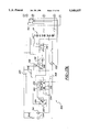
- FIGS. 17A and 17B are schematic circuit diagrams illustrating the electrical connections and functional control elements of the electric drive riding greens mower of the present invention.
- the present invention is directed to an all electric operating riding greens mower.
- the invention is described as follows embodied as an electric triplex greens reel mower having a frame supported on three wheels, three reel type lawn mowers supported from the frame member, an operator station including a seat from which an operator controls the function of the mower and an on-board battery power source of electrical energy. It should be readily understood that the teachings of the present invention are not limited to the specific type of greens mower described herein and can be extended to a variety of applications in the turf care industry and elsewhere.
- FIGS. 1-6 illustrate the general arrangement of electric riding greens mower 10.
- Mower 10 includes a frame 12 supported for movement on forward drive wheels 14 and rear steerable wheel 16.
- Three reel type lawn mowers 18a, 18b and 18c, respectively, are supported from frame 12 by reel lift assemblies 190.
- Two of the reel lawn mowers 18a and 18b, are disposed at the forward corners of frame 12 and the third reel lawn mower 18c is centrally disposed below frame 12. This arrangement assures that the mowers precede the ground engaging wheels such that the green turf is mowed prior to being traversed by the ground engaging wheels thereby ensuring a precise and consistent length of cut.
- Battery power source 24 preferably provides between about 12 volts to 96 volts of electrical force.
- battery power source 24 includes eight six six volt lead-acid batteries 26 connected in series to provide 48 volts of electrical force and further providing capability for cutting between in excess of 20 average golf course greens including transportation of mower 10 between the greens.
- lower battery voltages may be used with smaller units while higher battery voltages may be used with larger units such as five gang fairway mowers.
- Battery power source 24 is rechargeable, and it should be readily understood that any type of batteries, such the above-mentioned lead acid or nickel cadmium (NiCad) batteries, may be used with mower 10.
- Battery power source 24 also provides electrical energy to a drive motor 162 which is adapted to provide driving torque through a drive axle 164 to each of the drive wheels 14 for propelling mower 10 over a green being mowed or between greens.
- Drive motor 162 is capable of providing an average cutting speed for mower 10 of approximately 3.8 miles per hour (MPH) during mowing operations and approximately 7.5 MPH during transport.
- battery power source 24 is secured to a battery support 40 which is made integral to a rearward portion of frame 12.
- Battery support 40 includes a plurality of transverse "L" shaped members 42 which define a pair of channels 44 and 46, respectively.
- Channels 44 and 46 are sized to receive the eight lead-acid batteries 26 of battery power source 24 in two rows of four.
- Channels 44 and 46 are separated by a vertical plate member 48 which also forms a portion of a seat support 64.
- Vertical plate member 48 is formed with a plurality of apertures 50 to reduce its weight and hence the overall weight of mower 10.
- the forward channel 44 is further shielded from the forward portion of mower 10 by contoured vertical plate member 52 which also forms a portion of seat support 64.
- upper support member 56 also constructed from a plurality of "L" shaped members is secured over the tops of batteries 26. Batteries are then connected in series via jumpers 45 as shown in FIG. 8, to provide up to approximately forty-eight volts of electrical force.
- battery power source 24 is covered with a vented cover 54.
- Cover 54 has a dome shaped contour and overlaps the outer portions of frame 12 to cover battery power source 24 as well as steering mechanism 260.
- Cover 54 further includes an aperture 58 which is located at the apex of the domed shape. Aperture 58 permits the escape of gases generated during recharging of the batteries 56 without having to remove cover 54. Additional apertures 57 are formed in the upper side portions of cover 54 into which vented plugs 59 are inserted for further ensuring adequate ventilation of battery power source 24.
- Mower 10 is operated from an operator station 60 which includes a seat 62 supported above frame 12 and battery power source 24 by seat support 64.
- Operator station 60 also includes a control support arm 66 which is secured to a rearward portion of the frame 12.
- Control support arm 66 extends forwardly and around the seat 62 such that a steering wheel 68 is located directly in front of the operator and a control module 70 for housing the control elements such as control switches and indicators is within view and reach of the operator.
- Located on control support arm 66 and adjacent steering wheel 68 is a communication panel 72 as best seen in FIG. 12, which will be described in more detail hereinlater, and which is operable for displaying mowing and operating instructions to the operator.
- Formed integral to frame 12 and associated with operator station 60 is foot deck 74. Foot deck 74 is ergonomically angled for operator comfort and ease of reaching the drive pedal 76, brake pedal 78 and reel mower activation switch (mow switch) 80.
- Seat 62 further includes an assist handle 82 for assisting the operator on and
- FIGS. 7, 14 and 15 illustrate seat support 64 including vertical plate member 48, contoured vertical plate member 52 and assist handle 82 and further including horizontal plate member 84, track members 86 and seat base support 88.
- Threaded fasteners 90 and bushing 92 pivotably secure a first end of horizontal plate member 84 to apertures 94 formed in tabs 96 formed on contoured vertical plate member 52.
- horizontal plate 84 is supported on vertical plate member 48 and is secured by a threaded knob 98 which engages a stud 100 extending vertically upwardly from vertical plate member 48 and passing through aperture 58 in cover 54 and an aperture 102 formed in horizontal plate 84.
- Track members 86 are operable for allowing fore and aft adjustment of seat 62 relative to the seat support 64 and hence frame structure 12 of mower 10 to enhance operator comfort and ease of operating mower 10.
- Track members 86 are secured, such as by threaded fasteners, to horizontal plate 84.
- threaded knob 98 is detached from stud 100, and seat 62, including base support 88, track members 86 and horizontal plate 84, may be pivoted to a past vertical position for removing cover 54 and accessing battery power source 24 and steering mechanism 260.
- assist handle 82 also pivots with seat and therefore may be used to assist in pivoting seat 62 as well as for assisting an operator on and off mower 10.
- FIGS. 10 and 11 illustrate the details of the ergonomically oriented foot deck 74.
- foot deck 74 includes a drive pedal 76, a brake pedal 78 and mow switch 80 the functions of which will be described later. Both the drive pedal 76 and the brake pedal 78 are covered with a non-slip surface coating as is a portion 120 of foot deck adjacent the mow switch 80.
- a portion of foot deck 74 is a panel 122 which is hingedly mounted to the foot deck 74 and can be opened to reveal the electrical components and wiring connections for mower 10 which are mounted in a i compartment 124 under the foot deck or to the panel 122 itself.
- FIG. 3 illustrates the routing of wiring harness through tubular frame 12. In this manner a number of brackets and tie-downs necessary for securing wiring harness 123 to mower 10 can be eliminated as well protective sheathing which would be required if wiring harness 126 were exposed thereby saving on cost and weight of mower 10.
- compartment 124 is formed with apertures 128 which allow for water which may accumulate in compartment 124 to drain due to the angle of foot deck 74.
- FIG. 12 further illustrates features of operator station 60 including the position of steering wheel 68 mounted to control support arm 66 in its relation to seat 62.
- a control panel 130 is provided and secured to control support arm 66.
- Control panel 130 contains a plurality of electrical switches generally indicated at 132 for changing the operating conditions of mower 10 as well as a of plurality gages 134 to monitor the operation of mower 10.
- switches 132 are provided and secured to control panel 130 for selectively controlling operation of reel mowers 18a, 18b and 18c, activating the head-light 304 and the like.
- indicator gages 134 show hours of operation, battery charge state, and the like.
- Communication panel 72 is secured to control support arm 66 such as by adhesive, hook and loop fasteners or by securing it under a clear plastic panel.
- Communication panel 72 allows the greens supervisor to provide mowing instructions to the operator.
- Communication panel 72 is constructed from plastic or other suitable material to allow it to be written on in grease pencil or dry erase marker and hence, the instructions can be changed on a daily basis.
- communication panel includes a plurality of zones 138 which define particular operations and operating parameters and a plurality of blank zones 140 in which the supervisor may mark instructions.
- a dial indicator 142 which allows the supervisor to indicate the direction in which to mow a particular green.
- a line between 9 and 3 would indicate the direction in which the operator should traverse the green while mowing, and circling CW or CCW indicates the direction in which to perform a clean-up cut if required.
- Several communication panels 72 may be prepared and selectively inserted behind the clear plastic panel, or otherwise affixed to control support arm 66, by the operator. Hence, the supervisor may prepare all of the instructions that the operator may need for an entire day at one time, and the operator may view the instructions while operating the machines to ensure proper mowing of the green.
- FIG. 4 shows the prime mover 160 for mower 10 which includes a series-wound DC motor 162 adapted to deliver driving torque via drive axle 164 to each of the drive wheels 14. More particularly, drive motor 162 engages a gear reduction assembly 166 which includes a differential gear assembly housed therein. Gear reduction assembly 166 provides driving torque to a pair of shafts which are journally supported within drive axle 164 and which are operable to deliver drive torque to wheels 14.
- a suitable drive motor 162 is a 48 volt 2 horsepower (HP) at 2800 revolutions per minute (RPM) DC motor, and a suitable drive axle 164 is a 15.67:1 gear reduction axle adapted to have motor 162 secured directly thereto.
- a single brake assembly 182 is secured to drive axle 164 and is interconnected with brake pedal 78 for providing braking means.
- the weight of prime mover 160 is isolated toward a forward portion of mower 10 and substantially over the front drive wheels 14. More particularly, drive motor 162 is mounted to drive axle 164 forward of the axis of rotation of drive wheels 14 such that the majority of the weight of drive motor 162 is distribute to the front drive wheels 14. The remaining weight of prime mover 160, i.e., the weight of the drive axle 164 is substantially distributed along the axis of rotation of drive wheels 14.
- drive motor 162 is mounted directly to drive axle 164 and forward thereof.
- Drive axle 164 is secured to mower 10 via threaded fasteners to brackets 178 suitably secured to an outer portion of frame 12.
- Mounting bracket 180 is provided and adapted to support a pair of reel lift assemblies 190 for supporting reel lawn mower 18a and 18b to a forward portion of mower 10.
- Each of the reel lift assemblies 190 include an arm member 184 pivotably supported at one end to mounting bracket 180 and fitted with a forwardly extending support member 186 including a sleeve 188 at the other end.
- Reel lift assemblies 190 each include a reel lift motor 192 supported to a case 194 and an actuating shaft 196 supported for axial movement relative to sleeve 188 secured to case 194.
- Reel lift motor 192 drives a ball screw assembly (not shown) housed within case 194 which causes linear movement of shaft 196 relative to sleeve 188.
- a distal end of shaft 196 includes a bore 198 through which a pin 200 is secured with pin 200 also engaging a pair of slots 202 formed through plates 204 secured to arm 184.
- reel mower motor 22 is directly mounted to a bearing housing portion 168 of the reel mowers 18a-18c and is directly coupled to the cutting cylinder (not shown).
- the cutting cylinder is journally supported within the reel mower frame 172 which is adapted to a pull frame 178 in a known manner.
- Pull frame 178 includes a transverse frame member 179 and a steering shaft 206 which is journally supported on arm 186 by sleeve 208 in a known manner as shown in FIG. 4.
- linear movement of shaft 196 in a first direction causes engagement of pin 200 with slots 202 and an upward pivoting movement of arm 184 about mounting bracket 180 and hence a lifting of the associated reel mower from a lowered operative position to a raised non-operative position.
- linear movement of actuating shaft 196 in a second direction causes a downward pivoting movement of 184 arm about mounting bracket 180 and a lowering of the associated reel mower to the operative position.
- Slots 202 are sized to permit an amount of upward and downward travel of the reel mower in the operative position such that the reel mower may traverse undulating terrain without binding against the pin 200.
- FIGS. 1, 4, 7, 8 and 15 illustrate the center reel mower 18c pivoting mount 230.
- Pivoting mount 230 includes an arm member 232 to which a lift actuation mechanism 234, similar to that previously described, is secured to a first end.
- a second end of arm member 232 is pivotably mounted to a rear portion of frame 12.
- a sleeve 236 is secured, such as by welding, to a rear portion of frame 12.
- Journally received within the sleeve 236 is a swivel pin 238 which is secured to the second end of arm member 232 thereby allowing pivoting motion of arm member 232 about a vertical axis located at a rearward portion of frame 12.
- center reel 18c may be pivoted from an operative position below frame 12 to a service position adjacent frame 12.
- FIG. 8 shows reel mower 18c pivoted midway between the operative position and the service position.
- Bracket member 240 is secured to the first end of arm member 232.
- Bracket member 240 includes first and second transversely extending vertical flanges 242 and 244, respectively.
- An upper portion of flange 242 further includes a rearwardly extending portion 246 to which a latch assembly 248 is secured.
- Latch assembly 248 includes an over-center toggle member 250 and a hook 252 secured thereto.
- An upper portion of hook 252 is formed with a substantially right angle bend portion 254 which projects through an aperture 256 formed in the upper portion of flange 242. Bend portion 254 is oriented to engage a catch 258 secured to a side portion of frame 12.
- a clamping load is applied between hook 252 and catch 258 by over-center toggle 250 for securing arm member 232 in its operative position with respect to frame 12.
- Lift actuator assembly 234 is pivotably secured to bracket 242, and operates as described above for raising and lowering center reel mower 18c.
- FIGS. 1-4 and 6 show the mounting of rear steerable wheel 16, the steering mechanism 260 and the interconnection between steering mechanism 260 and steering wheel 68.
- rear wheel 16 is mounted to a pair of brackets 262 secured to a "U" shaped yoke member 264.
- Yoke member 264 includes an upper spindle portion 266 which is journally supported within sleeve 268 secured to brackets 270 and which in turn are secured to frame 12.
- Spindle 266 projects upwardly through sleeve 268 such that a portion extends above frame 12 for allowing a steering sprocket 272 to be secured thereto.
- Steering sprocket 272 has a plurality of teeth 274 formed along its circumference for engaging an open ended chain 276.
- Cable assembly 278 is secured to the ends of chain 276 and is routed along a plurality of pulleys, examples of which are shown at 280 and 282, respectively, to steering wheel 68. It should thus be appreciated that rotation of steering wheel 68 causes concomitant movement of cable assembly 278 and hence rotation of steering sprocket 272 about sprocket axis "S" for turning rear wheel 16 and for steering mower 10.
- Rear wheel 16 is positioned aft of sprocket axis "S” such that it trails sprocket axis "S” for preventing flutter and enhancing stability of rear wheel 16.
- Cable assembly 278 can be routed through control support arm 66 which is constructed from tubular materials reducing cost and weight through the elimination of brackets and protective sheathing.
- FIGS. 17A and 17B show in schematic form the power and control circuit 300 for supplying electrical energy from battery power source 24 to reel mower motors 22, reel lift motors 192 and drive motor 162 previously described.
- Circuit 300 is arranged to provide twelve and twenty-four control voltages to a plurality of electro mechanical relay devices, while power devices are controlled at forty-eight and twenty-four volts as will be described below. It should also be understood that solid state devices may be substituted for those described without departing from the fair scope of the invention.
- Circuit 300 includes a lock-out, and the operator must insert a key into key switch 302 to activate mower 10.
- Key switch 302 is a two position dual pole switch which is closed in an ignition on position. When closed, operation of the head-light 304 through activation of head-light switch 306 is permitted. Further operation of mower 10 is prohibited unless seat switch 308 is closed, i.e., unless an operator is sitting in seat 68.
- key-switch-on relay 310 is energized at twelve volts which closes a first contactor for supplying a twelve volt signal to the motor controller 31 2 and for energizing a power on lamp 314. Energization of key-switch-on relay 310 also closes a second contactor which is necessary for supplying twenty-four volts to the reel mower contactor coils 342 and the reel lift motors, as will be described.
- drive motor 162 is controlled through cooperation of motor controller 312, foot actuated potentiometer 318 and forward/reverse contactor 320.
- Battery voltage is supplied to motor controller 312, which is operable to split the battery voltage and supply foot actuated potentiometer 318 with an input voltage.
- Foot actuated potentiometer 318 divides this input voltage depending on the position of drive pedal 76 and a "tap" voltage is returned to motor controller 312 which responds by modulating the current flowing through drive motor field coil 328 in proportion to the tap voltage for controlling the output speed of drive motor 162.
- drive motor 162 is a D.C. series-wound reversible motor.
- a first pole of drive motor 162 is connected directly to the full battery power source 24, i.e., forty-eight volts.
- the second pole of drive motor 162 is connected to the motor controller 312 which provides an interruptable ground connection.
- Motor controller 312 in cooperation with forward/reverse contactor 320, forward microswitch 324 and reverse microswitch 326 supplies and modulates field current to drive motor field winding 328 for controlling drive motor 162 speed.
- Forward microswitch 324 and reverse microswitch 326 are normally open and are disposed adjacent drive pedal 76 such that rotation of drive pedal 76 in a first direction closes forward microswitch 324 while rotation of drive pedal 76 in the opposite direction closes reverse microswitch 326.
- foot actuated potentiometer 318 is operable in both directions to divide the input voltage and to supply a tap voltage to motor controller 312. In this regard, foot actuated potentiometer 318 is operable to control mower 10 ground speed in both forward and reverse directions.
- Forward/reverse contactor 320 (shown completely de-energized in FIG. 17A) is a four position, four pole dual input relay.
- Forward and reverse cause closing of forward and reverse contactors, 330 and 332, respectively, within forward/reverse contactor 320.
- forward contactor 330 When the forward contactor 330 is closed and reverse contactor 332 is open, field current is applied from S1 to S2 on motor field winding 328, and drive motor 162 operates in a forward mode in response to current flow through drive motor armature winding 322.
- reverse contactor 332 when reverse contactor 332 is closed and forward contactor 330 is open, field current is applied from S2 to S1 on motor field winding 328, and drive motor 162 operates in a forward direction in response to current flow through drive motor armature winding 322.
- hour meter 334 Also included and activated when forward contactor is closed, is hour meter 334 for logging the hours of operation of mower 10.
- Mow switch 80 is a foot operated dual pole two position switch while transport switch 86 is a dual pole two position switch mounted to control panel 70.
- Mower 10 is designed to operate in two modes based on the position of transport switch 86.
- the reel mowers When in the transport mode, mower 10 is operable to travel at higher speeds, the reel mowers may be raised and lowered, but reel mower operation through actuation of mow switch 80 is inhibited.
- a mow mode i.e., transport switch 86 in the mow position, mower 10 operates at a lower mow speed, mow switch 80 is operable to activate and deactivate the reel mowers for mowing. The reel mowers may still be raised manually through operation of a second switch.
- Each of the reel mowers 18a-18c operate in essentially the same manner, and the following discussion for actuating a single reel mower is applicable to each.
- mow relay 336 With transport switch 86 in the transport mode, mow relay 336 is energized and the coil of main contactor 338 is switched to an open/de-energized state. Also, reel mower contactor coil 342 is also in an open/de-energized state as is the reel mower relay 344.
- Raise/lower switch 340 is a three position switch which is normally open. If moved to the raise "u" position, main contactor coil 338 is energized introducing a +24 volt differential across the reel lift motor 192 and it operates to raise the reel mower as previously described. If moved to the lower "d" position, the reel mower relay coil is energized, and -24 volts is introduced across reel lift motor 192 which operates to lower the reel mower as previously described. During each of these operations the reel mower motor contactor coil remains in an open/de-energized state, and therefore, the reel mower does not operate.
- mow relay coil 330 With continued reference to FIG. 17B placing transport switch 86 in the mow mode, de-energizes mow relay coil 330. Main contactor 338 coil is energized and its contacts close. In addition, when mow switch 80 is switched to mow, mower contactor coil 342 is energized which closes its contacts and introduces +48 volts across the reel mower motor 22 causing it to operate. Also, closing reel mower relay 344 contactors introduces -24 volts across reel lift motor 192 which lowers the reel mower into contact with the green and mowing begins.
- potentiometer relay 348 is de-energized thereby moving its contacts and introducing an additional resistor 346 in series with foot actuated potentiometer 318 reducing the tap voltage seen by motor controller 312.
- Motor controller 312 in response to the reduced tap voltage, reduces the current flow through drive motor armature winding 322 and likewise reduces the speed of the mower 10 to mowing speed.
- mow switch 80 Upon completing a pass across the green being mowed, the operator switches mow switch 80 to off "O". This de-energizes reel mower contactor coil 342 and the reel mower motor ceases operating and are raised. Also, the reel mower relay 344 is de-energized, and mow relay 336 is energized opening main contactor 338. With both transport switch 86 in the mow mode, and mow switch 80 in the mow position, raise switch 340 remains operable, as described, to raise and lower reel mowers 18a-18c. When generally mowing, transport switch 86 is left in the mow position and control of reel mowers 18a-18c is controlled through selective activation of mow switch 80.
- Circuit 300 includes an on/off delay timer 350 for reel mower 18c.
- on/off delay timer 350 delays the time before reel mower 18c is activated and lowered such that it starts cutting at substantially the same position as reel mowers 18a and 18b.
- on/off delay timer 350 delays the deactivation of reel mower 18c such that it stops cutting at substantially the same position as reel mowers 18a and 18b.
- on/off delay timer 350 may be a simple RC timer circuit, a 555 timer chip, or digital timer circuit, which is preferred.
- FIG. 16 illustrates the on/off delay feature for reel mowers 18a, 18b and 18c. The high going trace indicates mower activation, while a low going trace indicates mower deactivation.
- FIGS. 1-6 and 15 illustrate the frame assembly and the mounting of the prime mover and other frame components.
- Mower 10 incorporates a single drive motor 162 adapted to drive the forward driven wheels 14 through drive axle 164, thus reducing weight over having multiple drive motors.
- the frame is constructed from tubular frame members. The tubular frame provides for enhancing structural rigidity of the electric drive riding greens mower 10 while reducing weight.
- tubular frame permits routing of wiring harness 126 and steering cable assembly 278 through the frame 12 and control support arm 66, respectively, to the various positions on the riding greens mower.
- the foot deck 174 also defines the electrical component mounting panel 122 and electrical compartment 124 all of which is integrally constructed into frame 12.
- the battery support structure 40 including vertical plates 48 and 52 also serves to support seat 62.
- the control support arm 66 supports steering wheel 68 and control panel 70 as well as functions as a conduit for steering cable assembly 278.
- Mower 10 is designed with an increased tread width, i.e., the distance between centerlines of front drive wheels 14. This arrangement improves stability and ensures that rear steerable wheel 16 remains within the arc defined by drive wheels 14 during turns. Thus, the operator is assured that if drive wheels 14 have cleared a hazard, rear steerable wheel 16 will similarly clear the hazard.
- the positioning of rear steerable wheel 16, however, also takes into account the desirability of elongating the wheel base to enhance stability of mower 10. Hence, rear steerable wheel 16 is positioned as far aft as possible while still achieving the above goals with the wheel base being approximately in the ratio of 1:1 to the tread width.
- Mower 10 is also designed to be highly serviceable. As noted above, batter cover 54 is vented so that battery power source 24 may be recharged without having to remove battery cover 54.
- the seat 62 is pivotable to allow access to battery power source. Also, as described, center reel mower 18c is secured to pivoting mount 230 so that it is easily pivoted out from under mower 10 for service. Furthermore, a majority of the electrical components are conveniently mounted to a pivoting panel such that they are easily accessed for service.
- electrical energy is communicated to the reel mowers 18a-18c from battery power source 24 along lead 364 and to the reel mower via lead 360.
- connectors 366 and 362 joining leads are disconnected.
- main power connector which isolates battery power source 24 from the rest of the electrical system.
- a backlapping accessory box which includes a pair of leads, an on/off switch and a knob connected to a potentiometer disposed within the box.
- a first lead of the accessory box is connected to an external power source and the other lead is connected to lead 360 at connector 362.
- the knob can be rotated to adjust the potentiometer such that the speed at which the reel mower is driven in reverse can be adjusted.
- the reel mowers may be conveniently backlapped without removing them from mower 10.
- the backlapping accessory could also be adapted to receive power from battery source 24 eliminating the need for an external power source.
- reel mower end cover 380 covers an elongated end portion 382 of the shaft of a reel cylinder.
- cover 380 is adapted to receive an auxiliary reel mower motor which engages shaft end portion 382.
- the auxiliary reel mower motor is simply a standard reel mower motor adapted to be removably secured to the reel mower and cover 382. Electrical energy is provide from an adjustable external source, or from battery power source 24 via lead 360 through an adjustment means, and auxiliary reel mower motor drives the reel mower in reverse for providing a second means for backlapping the reel mower.
Landscapes
- Life Sciences & Earth Sciences (AREA)
- Environmental Sciences (AREA)
- Harvester Elements (AREA)
Abstract
Description
Claims (39)
Priority Applications (2)
Application Number | Priority Date | Filing Date | Title |
---|---|---|---|
US08/418,936 US5540037A (en) | 1994-02-03 | 1995-04-07 | Control system for electric drive riding mower |
US08/541,922 US5553445A (en) | 1994-02-03 | 1995-10-10 | Riding mower with swingout center mower head |
Applications Claiming Priority (2)
Application Number | Priority Date | Filing Date | Title |
---|---|---|---|
US08/191,553 US5406778A (en) | 1994-02-03 | 1994-02-03 | Electric drive riding greens mower |
US08/418,936 US5540037A (en) | 1994-02-03 | 1995-04-07 | Control system for electric drive riding mower |
Related Parent Applications (1)
Application Number | Title | Priority Date | Filing Date |
---|---|---|---|
US08/191,553 Division US5406778A (en) | 1994-02-03 | 1994-02-03 | Electric drive riding greens mower |
Related Child Applications (1)
Application Number | Title | Priority Date | Filing Date |
---|---|---|---|
US08/541,922 Division US5553445A (en) | 1994-02-03 | 1995-10-10 | Riding mower with swingout center mower head |
Publications (1)
Publication Number | Publication Date |
---|---|
US5540037A true US5540037A (en) | 1996-07-30 |
Family
ID=22705947
Family Applications (3)
Application Number | Title | Priority Date | Filing Date |
---|---|---|---|
US08/191,553 Expired - Lifetime US5406778A (en) | 1994-02-03 | 1994-02-03 | Electric drive riding greens mower |
US08/418,936 Expired - Lifetime US5540037A (en) | 1994-02-03 | 1995-04-07 | Control system for electric drive riding mower |
US08/541,922 Expired - Lifetime US5553445A (en) | 1994-02-03 | 1995-10-10 | Riding mower with swingout center mower head |
Family Applications Before (1)
Application Number | Title | Priority Date | Filing Date |
---|---|---|---|
US08/191,553 Expired - Lifetime US5406778A (en) | 1994-02-03 | 1994-02-03 | Electric drive riding greens mower |
Family Applications After (1)
Application Number | Title | Priority Date | Filing Date |
---|---|---|---|
US08/541,922 Expired - Lifetime US5553445A (en) | 1994-02-03 | 1995-10-10 | Riding mower with swingout center mower head |
Country Status (4)
Country | Link |
---|---|
US (3) | US5406778A (en) |
EP (1) | EP0741510B1 (en) |
AU (1) | AU1733895A (en) |
WO (1) | WO1995020868A1 (en) |
Cited By (49)
Publication number | Priority date | Publication date | Assignee | Title |
---|---|---|---|---|
US5727372A (en) * | 1996-05-30 | 1998-03-17 | The Toro Company | On-board charging system for electric lawn mower |
US5797458A (en) * | 1997-02-05 | 1998-08-25 | Deere & Company | Aerator control mechanism |
US5865016A (en) * | 1997-02-07 | 1999-02-02 | Ransomes America Corporation | Release mechanism for cutting head of a gang mower |
GB2331908A (en) * | 1997-12-03 | 1999-06-09 | Joseph Charteris | Cordless electric grass lawn mower |
US5934051A (en) * | 1997-02-06 | 1999-08-10 | Textron, Inc. | Solid state mow system for electrically powered mower |
US5934053A (en) * | 1996-11-01 | 1999-08-10 | Fillman; Alan R. | Removable battery tray system for an electrically powered mower |
US6029762A (en) * | 1997-01-22 | 2000-02-29 | Textron Inc. | Battery warmer for extending the range of an electrically powered vehicle |
US6082082A (en) * | 1997-02-14 | 2000-07-04 | Textron Inc. | Dual motor drive system for electrically powered mower |
US6109009A (en) | 1998-01-16 | 2000-08-29 | Textron Inc. | Constant speed control for electric greens mower |
US6326765B1 (en) | 2000-10-04 | 2001-12-04 | Vectrix Corporation | Electric scooter with on-board charging system |
US6449934B1 (en) * | 1995-11-13 | 2002-09-17 | Ransomes America Corporation | Electric riding mower with motor generator set and noise abatement |
US6668530B2 (en) * | 2002-03-13 | 2003-12-30 | Generac Power Systems, Inc. | Grass-cutting tractor with improved operating features |
US20040055802A1 (en) * | 2002-08-02 | 2004-03-25 | Oshkosh Truck Corporation | Refuse vehicle control system and method |
US20050004733A1 (en) * | 1999-07-30 | 2005-01-06 | Oshkosh Truck Corporation | Concrete placement vehicle control system and method |
US20050023793A1 (en) * | 2003-08-01 | 2005-02-03 | Harry Fu | Pedal scooter |
US20050086919A1 (en) * | 2003-10-28 | 2005-04-28 | Stiefvater Thomas L. | Wobble drive for windrower header |
US20050108999A1 (en) * | 2003-11-21 | 2005-05-26 | Ariens Company | Lawnmower tilt sensor apparatus and method |
US20050257512A1 (en) * | 2004-05-21 | 2005-11-24 | Derby Harry L V | Internal combustion engine traction drive with electric cutting unit drive for walking greens mower |
US7007446B2 (en) * | 2000-10-26 | 2006-03-07 | Textron Inc. | Battery-powered walk-behind greensmower |
US20070095039A1 (en) * | 2005-11-01 | 2007-05-03 | Textron Inc. | Modular power source for riding mower |
US20070209344A1 (en) * | 2006-03-10 | 2007-09-13 | Textron Inc. | Sharpness monitor for indicating turf mower reel blade condition |
EP1852008A1 (en) | 2006-05-05 | 2007-11-07 | Deere & Company | Grass mowing machine |
US7328563B1 (en) * | 2002-10-11 | 2008-02-12 | The Toro Company | Walk reel mower with electric reel and traction drives |
US20080060331A1 (en) * | 2006-09-12 | 2008-03-13 | Deere & Company, A Delaware Corporation | Offsetting cutting units for a grass mowing machine |
US20080103651A1 (en) * | 1999-07-30 | 2008-05-01 | Oshkosh Truck Corporation | User interface and method for vehicle control system |
US20080196371A1 (en) * | 2007-02-20 | 2008-08-21 | Textron Inc. | Electrically Driven, Reel-Mower Accessories |
US20090192691A1 (en) * | 2008-01-28 | 2009-07-30 | Textron Inc. | Turf Maintenance Vehicle All-Wheel Drive System |
US7578116B1 (en) | 2007-08-10 | 2009-08-25 | Richard D. Meyer | Battery-operated riding rotary mower |
WO2010063906A1 (en) | 2008-12-05 | 2010-06-10 | Elodys International | Method and device for the regeneration of polluted scrubbing solutions |
US7848857B2 (en) | 2001-01-31 | 2010-12-07 | Oshkosh Corporation | System and method for braking in an electric vehicle |
US7854293B2 (en) | 2007-02-20 | 2010-12-21 | Textron Innovations Inc. | Steering operated by linear electric device |
US7908850B1 (en) | 2006-03-10 | 2011-03-22 | Hydro-Gear Limited Partnership | Actuator assembly |
US7984662B1 (en) | 2003-11-17 | 2011-07-26 | Hydro-Gear Limited Partnership | Vehicle direction sensing mechanism |
EP2361493A2 (en) | 2010-02-17 | 2011-08-31 | Deere & Company | Reel mower cutting unit |
US8130478B2 (en) | 2009-04-07 | 2012-03-06 | Deere & Company | Power limiting system for multiple electric motors |
US8139109B2 (en) | 2006-06-19 | 2012-03-20 | Oshkosh Corporation | Vision system for an autonomous vehicle |
WO2012158150A1 (en) * | 2011-05-13 | 2012-11-22 | Husqvarna Consumer Outdoor Products N.A., Inc. | Vehicle battery storage compartment |
WO2013008812A1 (en) | 2011-07-12 | 2013-01-17 | ヤンマー株式会社 | Mobile electric work machine |
US20140165524A1 (en) * | 2011-07-14 | 2014-06-19 | Husqvarna Ab | Riding Lawn Mower Including Battery Powered Drive System |
US8769917B1 (en) * | 2009-10-29 | 2014-07-08 | Jeffrey E. Howell | Battery-operated compact riding rotary mower |
US8947531B2 (en) | 2006-06-19 | 2015-02-03 | Oshkosh Corporation | Vehicle diagnostics based on information communicated between vehicles |
US20150116132A1 (en) * | 2013-10-31 | 2015-04-30 | Delta Systems, Inc. | Smart monitoring system and method of operation |
US9686909B2 (en) | 2011-07-14 | 2017-06-27 | Husqvarna Ab | Battery powered lawn care vehicle with drive efficiency indicator |
US9699965B2 (en) | 2011-07-14 | 2017-07-11 | Husqvarna Ab | Articulated riding lawn mower including distributed battery system |
US9845191B2 (en) | 2013-08-02 | 2017-12-19 | Oshkosh Corporation | Ejector track for refuse vehicle |
US20210155099A1 (en) * | 2019-11-21 | 2021-05-27 | Globe (Jiangsu) Co., Ltd | Riding mower |
US11653598B2 (en) | 2017-12-28 | 2023-05-23 | Nanjing Chervon Industry Co., Ltd. | Electric riding lawn mower |
US11917945B2 (en) | 2021-06-25 | 2024-03-05 | Nanjing Chervon Industry Co., Ltd. | Outdoor moving device |
EP4385304A1 (en) * | 2022-08-23 | 2024-06-19 | Black & Decker, Inc. | Electric lawn mower including an energy absorbing module |
Families Citing this family (81)
Publication number | Priority date | Publication date | Assignee | Title |
---|---|---|---|---|
US5406778A (en) | 1994-02-03 | 1995-04-18 | Ransomes America Corporation | Electric drive riding greens mower |
US5402110A (en) * | 1994-02-03 | 1995-03-28 | Ransomes America Corporation | Hydraulic fluid leak detection system and method |
US5502957A (en) * | 1995-03-29 | 1996-04-02 | Robertson; Charles W. | Electric lawn mower with intelligent control |
US6035561A (en) * | 1995-06-07 | 2000-03-14 | Paytas; Karen A. | Battery powered electric snow thrower |
US6170179B1 (en) | 1995-06-07 | 2001-01-09 | Karen A. Paytas | Battery powered electric snow thrower |
US5713189A (en) * | 1995-08-16 | 1998-02-03 | Ransomes America Corporation | Interactive brake system for electric riding mower |
DE69723109T2 (en) * | 1996-02-09 | 2003-11-27 | The Toro Co., Minneapolis | MOWER WITH ELECTROMOTIC DRIVE |
US5890545A (en) * | 1996-05-06 | 1999-04-06 | Smithco, Inc. | Electric drive bunker rake |
US5970690A (en) * | 1997-10-24 | 1999-10-26 | Ransomes America Corporation | Leveling apparatus for a cutting head of a mower |
US6430902B1 (en) | 1997-12-09 | 2002-08-13 | Textron, Inc. | Mower cutting unit having an internal motor |
US6571542B1 (en) * | 1999-03-25 | 2003-06-03 | Textron Inc. | Electric drive mower with interchangeable power sources |
US6330926B1 (en) | 1999-09-15 | 2001-12-18 | Hill-Rom Services, Inc. | Stretcher having a motorized wheel |
US6253533B1 (en) * | 1999-11-08 | 2001-07-03 | Textron Inc. | Lawnmower reel and drive motor assembly |
US7014000B2 (en) * | 2000-05-11 | 2006-03-21 | Hill-Rom Services, Inc. | Braking apparatus for a patient support |
US6749034B2 (en) | 2000-05-11 | 2004-06-15 | Hill-Rom Services, Inc. | Motorized traction device for a patient support |
US6834402B2 (en) | 2001-09-20 | 2004-12-28 | Hill-Rom Services, Inc. | Combination bed mover and patient transfer apparatus |
US7018157B2 (en) | 2001-09-20 | 2006-03-28 | Hill-Rom Services, Inc. | Powered transport apparatus for a bed |
US7032703B2 (en) * | 2002-06-17 | 2006-04-25 | Caterpillar Inc. | Operator control station for controlling different work machines |
US6684615B1 (en) * | 2002-07-19 | 2004-02-03 | Lastec, Inc. | Hinge system for articulating mower decks |
US6782964B1 (en) * | 2002-10-11 | 2004-08-31 | Deere & Company | Mower |
US7788892B2 (en) * | 2003-07-10 | 2010-09-07 | Deere & Company | User interface and control for cutting reel system |
US6946762B2 (en) * | 2003-08-26 | 2005-09-20 | Deere & Co. | Electric motor drive for a reel mower |
US6928798B2 (en) * | 2004-01-02 | 2005-08-16 | Textron Inc. | Swing out arm for rear rotary deck |
US7290635B2 (en) * | 2004-07-02 | 2007-11-06 | Caterpillar Inc. | Work machine operator control station with moveably attached controller |
US7146786B2 (en) * | 2004-07-27 | 2006-12-12 | Dennis Brandon | Electric linear deck lift assembly |
WO2006086412A2 (en) * | 2005-02-09 | 2006-08-17 | The Toro Company | Mower with hybrid prime mover |
US7367173B2 (en) * | 2005-03-02 | 2008-05-06 | Textron Inc. | Greens mower data display and controller |
US7677017B2 (en) * | 2005-06-28 | 2010-03-16 | Textron Innovations Inc. | Modular power source for walk-behind mower |
US20070000222A1 (en) * | 2005-06-30 | 2007-01-04 | Lawbaugh James W | Electrical pedal power mower |
US7568331B2 (en) * | 2005-12-21 | 2009-08-04 | Deere & Company | Extendable lift arms for trim mower |
US7797918B2 (en) * | 2005-12-27 | 2010-09-21 | The Toro Company | Mower with flip up armrest carrying operational controls and display |
US7882582B2 (en) * | 2006-10-13 | 2011-02-08 | Hill-Rom Services, Inc. | User interface and control system for powered transport device of a patient support apparatus |
US7886377B2 (en) | 2006-10-13 | 2011-02-15 | Hill-Rom Services, Inc. | Push handle with rotatable user interface |
US7594377B1 (en) | 2006-10-27 | 2009-09-29 | Sauer-Danfoss Inc. | Means of adjusting ground speed of a vehicle based on load on blade assembly |
US7475530B2 (en) * | 2007-03-02 | 2009-01-13 | Textron Inc. | Articulating swing-out arm |
US7865983B2 (en) * | 2007-04-26 | 2011-01-11 | Hill-Rom Services, Inc. | Patient care equipment support transfer system |
WO2009036208A1 (en) | 2007-09-11 | 2009-03-19 | Hydro-Gear Limited Partnership | Control systems and methods for electric drive utility vehicles |
US8207693B2 (en) | 2007-09-11 | 2012-06-26 | Hydro-Gear Limited Partnership | Controller assemblies for electric drive utility vehicles |
US7954308B2 (en) * | 2008-01-25 | 2011-06-07 | Deere & Company | Frequency of clip adjustment system and method for reel mower cutting unit |
US7789187B2 (en) * | 2008-01-29 | 2010-09-07 | Hill-Rom Services, Inc. | Push handle with pivotable handle post |
US7953537B2 (en) | 2008-02-29 | 2011-05-31 | Hill-Rom Services, Inc. | Algorithm for power drive speed control |
US20090266042A1 (en) * | 2008-04-25 | 2009-10-29 | Mooney P Wade | Mower |
EP2346709B1 (en) | 2008-10-23 | 2022-03-23 | Hydro-Gear Limited Partnership | Control systems and methods for electric motors of utility vehicles |
US20100313536A1 (en) * | 2009-06-11 | 2010-12-16 | Ron Berko | Double cut lawnmower attachment |
US20110011662A1 (en) * | 2009-07-15 | 2011-01-20 | International Truck Intellectual Property Company, Llc | Multi-function tank |
US8757308B2 (en) * | 2009-09-10 | 2014-06-24 | Hill-Rom Services Inc. | Powered transport system and control methods |
FR2956619B1 (en) * | 2010-02-24 | 2012-07-20 | Renault Sa | BATTERY CONNECTION SYSTEM FOR ELECTRIC VEHICLE AND BATTERY ASSEMBLY THEREFOR |
EP2805598A1 (en) * | 2010-03-01 | 2014-11-26 | Yanmar Co., Ltd. | Electric riding mower |
US9073539B1 (en) | 2010-06-22 | 2015-07-07 | Hydro-Gear Limited Partnership | Auxiliary battery powered brake release assembly |
CN103796504B (en) | 2011-07-14 | 2017-08-04 | 胡斯华纳有限公司 | Battery powered lawn-care car with effective drive control device |
EP2731820B1 (en) * | 2011-07-14 | 2019-09-25 | Husqvarna Ab | Riding lawn mower including battery powered cutting system |
GB2494206A (en) * | 2011-09-05 | 2013-03-06 | Ransomes Jacobsen Ltd | Self-propelled grass cutting machine |
US8727233B2 (en) | 2011-10-17 | 2014-05-20 | Champion Power Equipment, Inc. | Pressure spray washer and control |
US8857138B2 (en) | 2011-11-04 | 2014-10-14 | Briggs & Stratton Corporation | Starter system for an engine |
US8733072B2 (en) | 2011-11-04 | 2014-05-27 | Briggs & Stratton Corporation | Starter system for an engine |
US9127658B2 (en) | 2011-11-04 | 2015-09-08 | Briggs & Stratton Corporation | Internal combustion engine including starting system powered by lithium-ion battery |
US9707143B2 (en) | 2012-08-11 | 2017-07-18 | Hill-Rom Services, Inc. | Person support apparatus power drive system |
US10130962B2 (en) | 2013-10-10 | 2018-11-20 | Briggs & Stratton Corporation | Wirelessly controlled trigger start and chemical tank change-over for pressure washers |
US9408344B1 (en) * | 2013-11-08 | 2016-08-09 | Hydro-Gear Limited Partnership | Three wheeled vehicle |
US10206321B2 (en) | 2014-02-04 | 2019-02-19 | Deere & Company | Aerator with variable delay of coring head |
CN106233494A (en) | 2014-03-06 | 2016-12-14 | 布里格斯和斯特拉顿公司 | For substituting the chargeable cell system of lead-acid battery |
JP6210916B2 (en) * | 2014-03-26 | 2017-10-11 | 株式会社Ihiシバウラ | Lawn mower |
US10130037B2 (en) | 2014-12-31 | 2018-11-20 | Mean Green Products, LLC | Electric mower apparatus and method of use |
DE102015012666A1 (en) | 2015-09-30 | 2017-03-30 | Bomag Gmbh | Construction machine, in particular rubber wheel or road paver |
JP6230202B2 (en) * | 2016-03-18 | 2017-11-15 | 本田技研工業株式会社 | Working machine |
JP2017163935A (en) * | 2016-03-18 | 2017-09-21 | 本田技研工業株式会社 | Working machine |
USD795181S1 (en) | 2016-06-15 | 2017-08-22 | Briggs & Stratton Corporation | Battery |
NL2017010B1 (en) * | 2016-06-20 | 2018-01-04 | Matador Exploitatie B V | Electrically driven single-axle tractor |
CN107836211B (en) * | 2016-09-20 | 2024-03-15 | 苏州宝时得电动工具有限公司 | Electric tool and false start prevention control method thereof |
US10433485B2 (en) | 2017-08-08 | 2019-10-08 | Deere & Company | Triplex greensmower open foot platform |
JP7456598B2 (en) * | 2018-06-29 | 2024-03-27 | 株式会社ササキコーポレーション | Self-propelled work machines and control systems for self-propelled work machines |
US11540439B2 (en) | 2018-07-18 | 2023-01-03 | Ariens Company | Lawn mower including a control panel and movable seat |
CA3113664A1 (en) | 2018-10-17 | 2020-04-23 | Generac Power Systems, Inc. | Deck height control system |
US11032972B2 (en) | 2018-10-30 | 2021-06-15 | Deere & Company | Triplex greensmower open foot platform cover |
US20200253113A1 (en) | 2019-02-07 | 2020-08-13 | Textron Inc. | Gang-type lawn mower |
US10834869B2 (en) | 2019-02-20 | 2020-11-17 | Honda Motor Co., Ltd. | Lift assembly for a lawnmower and lawnmower having same |
US11032973B2 (en) | 2019-07-26 | 2021-06-15 | Generac Power Systems, Inc. | Battery-operated electric mower |
CN110771352A (en) | 2019-12-05 | 2020-02-11 | 常州格力博有限公司 | Lawn mower and battery package subassembly thereof |
KR102431983B1 (en) * | 2020-04-20 | 2022-08-12 | 엘지전자 주식회사 | Lawn Mowing Apparatus |
WO2022087113A1 (en) * | 2020-10-23 | 2022-04-28 | Greenfield Robotics Corporation | Robotic weed control apparatus and method |
US11753105B2 (en) * | 2021-08-30 | 2023-09-12 | Eric Rea | Three-wheel motor vehicle and control system |
Citations (106)
Publication number | Priority date | Publication date | Assignee | Title |
---|---|---|---|---|
US1401156A (en) * | 1920-06-05 | 1921-12-27 | Moto Mower Company | Lawn-mower |
US2417613A (en) * | 1944-08-22 | 1947-03-18 | John M Radabaugh | Electric motor control and differential gear drive for lawn mowers |
US3090184A (en) * | 1961-11-08 | 1963-05-21 | George Fisanick | Hydraulic horizontal sliding action gang mower |
US3103090A (en) * | 1960-08-05 | 1963-09-10 | Robert J Sutherlin | Specific vehicle mounting for gang mower |
US3106811A (en) * | 1962-05-16 | 1963-10-15 | Jacobsen Mfg Co | Powered gang lawn mower |
US3217824A (en) * | 1961-05-11 | 1965-11-16 | Jepson Ivar | Electric lawn mower with improved grounding means |
US3230695A (en) * | 1957-07-31 | 1966-01-25 | Scott & Sons Co O M | Safety controls for an electrical powered lawn mower |
US3339353A (en) * | 1964-01-23 | 1967-09-05 | Bonamarte Inc | Gang mower |
US3404516A (en) * | 1965-10-15 | 1968-10-08 | Allis Chalmers Mfg Co | Corn harvester |
US3425197A (en) * | 1967-08-07 | 1969-02-04 | Stanley Bernard Kita | Vehicle guidance apparatus |
US3429110A (en) * | 1965-08-09 | 1969-02-25 | Jacobsen Mfg Co | Gang lawnmower |
US3472005A (en) * | 1966-11-21 | 1969-10-14 | Jacobsen Mfg Co | Articularly mounted gang mowers on a tractor |
US3496706A (en) * | 1967-07-12 | 1970-02-24 | Sunbeam Corp | Electric rotary lawnmower and grass collection bag |
US3511033A (en) * | 1968-10-18 | 1970-05-12 | Jacobsen Mfg Co | Gang lawn mowing machine |
US3570226A (en) * | 1967-08-05 | 1971-03-16 | Hanning Elektro Werke | Electrically driven lawnmower |
US3572455A (en) * | 1968-05-24 | 1971-03-30 | Vern Alvin Brueske | Self-propelled, electric, three wheel maintenance cart |
US3581480A (en) * | 1969-09-30 | 1971-06-01 | Black & Decker Mfg Co | Multiple-function receptacle and interconnecting plugs therefor |
US3602772A (en) * | 1968-12-04 | 1971-08-31 | Wolf Geraete Gmbh | Protective circuit for electrically driven lawn mowers and the like |
US3603065A (en) * | 1969-09-26 | 1971-09-07 | Black & Decker Mfg Co | Cam safe switch actuator |
US3608284A (en) * | 1970-04-09 | 1971-09-28 | Deere & Co | Gang mower |
US3608285A (en) * | 1970-04-15 | 1971-09-28 | Deere & Co | Neutral start system for riding mowers |
US3612573A (en) * | 1970-04-06 | 1971-10-12 | Roseman Mower Corp | Gang mower |
US3613337A (en) * | 1970-04-09 | 1971-10-19 | Jacobsen Mfg Co | Gang lawn mower |
US3631659A (en) * | 1969-06-18 | 1972-01-04 | Philips Corp | Lawn mower |
US3641749A (en) * | 1970-10-05 | 1972-02-15 | Black & Decker Mfg Co | Baffle for electric lawnmower |
US3650097A (en) * | 1970-03-12 | 1972-03-21 | Warren K Van Hook | Programmed steering means for mowing apparatus or the like |
US3668844A (en) * | 1970-04-09 | 1972-06-13 | Jacobsen Mfg Co | Gang lawn mower with self-sharpening means |
US3698523A (en) * | 1969-10-20 | 1972-10-17 | Mowbot Inc | Self-propelled random motion lawnmower |
US3721076A (en) * | 1971-10-04 | 1973-03-20 | Deere & Co | Adjustable mower suspension system |
US3729912A (en) * | 1970-09-14 | 1973-05-01 | Black & Decker Mfg Co | Snap on shroud mounting |
US3731469A (en) * | 1972-01-24 | 1973-05-08 | Jacobsen Mfg Co | Convertible gang lawn mower |
US3732673A (en) * | 1971-07-27 | 1973-05-15 | L Winn | Motor drive for a lawn mower |
US3732671A (en) * | 1971-08-31 | 1973-05-15 | Deere & Co | Electric drive riding mower |
US3742685A (en) * | 1971-12-29 | 1973-07-03 | Stellar Ind Inc | Lawn mower with hydrostatic drive |
US3759019A (en) * | 1972-09-06 | 1973-09-18 | Black & Decker Mfg Co | Cantilever motor mounting and brush hold-down |
US3800480A (en) * | 1973-02-28 | 1974-04-02 | F Keating | Portable blade sharpener |
US3809975A (en) * | 1973-01-22 | 1974-05-07 | J Bartels | Motor speed control apparatus for an electrically powered vehicle |
US3832835A (en) * | 1973-01-08 | 1974-09-03 | Roseman Mower Corp | Seven gang hydraulic reel mower |
US3841069A (en) * | 1972-04-11 | 1974-10-15 | Wolf Geraete Gmbh | Electrically driven lawn mower |
US3895481A (en) * | 1972-12-11 | 1975-07-22 | Suffolk Lawn Mowers Ltd | Lawn mowers |
US3910016A (en) * | 1974-08-08 | 1975-10-07 | Jacobsen Mfg Co | Gang lawn mower |
US3918240A (en) * | 1974-09-16 | 1975-11-11 | Jacobsen Mfg Co | Hydraulic system for a gang lawn mower |
US3924389A (en) * | 1973-03-27 | 1975-12-09 | Stanley B Kita | Automatic lawn mower |
US3958398A (en) * | 1974-07-24 | 1976-05-25 | Outboard Marine Corporation | Starter interlock for self-propelled lawn mower |
US3992858A (en) * | 1975-12-01 | 1976-11-23 | Jacobsen Manufacturing Company | Hydraulic system for controlling a gang of lawn mowers |
US3999643A (en) * | 1975-12-22 | 1976-12-28 | Allis-Chalmers Corporation | Electrical interlock safety control to prevent operation of mower during reverse travel |
US4021996A (en) * | 1976-02-26 | 1977-05-10 | Bartlett Gordon E | Golf greens mower |
US4024448A (en) * | 1971-08-31 | 1977-05-17 | Gould Inc. | Electric vehicle battery charger |
US4064680A (en) * | 1975-08-08 | 1977-12-27 | The Black And Decker Manufacturing Company | Cordless twin blade lawnmower construction |
US4145864A (en) * | 1977-01-06 | 1979-03-27 | Brewster Jr Albert H | Battery powered lawnmower |
US4161858A (en) * | 1977-11-02 | 1979-07-24 | Brouwer Turf Equipment Limited | Gang mower |
US4180964A (en) * | 1977-04-04 | 1980-01-01 | Pansire Dino G | Self-propelled self-guiding lawn mower |
US4265146A (en) * | 1979-04-02 | 1981-05-05 | Horrell Charles I | Device for sharpening lawn mower blades |
US4301881A (en) * | 1979-05-08 | 1981-11-24 | Griffin Hugh A | Vehicle drive system |
US4306404A (en) * | 1980-02-07 | 1981-12-22 | Canadian General Electric Company Limited | Rectifier assembly for a lawn mower |
US4306402A (en) * | 1978-05-24 | 1981-12-22 | Ahi Whimpway Limited | Gang mowers |
US4307559A (en) * | 1979-03-28 | 1981-12-29 | Rahsomes Sims & Jefferies Limited | Turf maintenance machines |
US4318266A (en) * | 1980-12-15 | 1982-03-09 | Max Taube | Remotely controlled self-propelled power lawn mower |
US4330981A (en) * | 1981-03-04 | 1982-05-25 | Roseman Mower Corporation | Towable ganged mower |
US4333302A (en) * | 1981-03-13 | 1982-06-08 | Ronald Thomas | Combined A.C./D.C. electric lawn mower |
US4335569A (en) * | 1980-10-22 | 1982-06-22 | The Toro Company | Reel to bedknife adjustment system |
US4354569A (en) * | 1979-04-14 | 1982-10-19 | Heinz Eichholz | Electric vehicle |
US4370846A (en) * | 1980-10-17 | 1983-02-01 | Brouwer Turf Equipment Limited | Gang mower with single cylinder lifting mechanism |
US4395865A (en) * | 1981-01-28 | 1983-08-02 | Davis Jr Robert D | Self propelled lawn mower |
US4430604A (en) * | 1982-03-24 | 1984-02-07 | Echlin Inc. | Rectifier switch for electric lawn mowers |
US4479346A (en) * | 1981-03-31 | 1984-10-30 | Noel Chandler | Automatic electrical bed knife adjuster |
US4487006A (en) * | 1983-04-15 | 1984-12-11 | Scag Dane T | Lawn mower |
US4559768A (en) * | 1984-05-25 | 1985-12-24 | Dunn Robert M | Power-driven lawnmower |
US4589249A (en) * | 1980-12-15 | 1986-05-20 | Walker Manufacturing Company | Mowing apparatus |
US4642976A (en) * | 1985-09-20 | 1987-02-17 | Owens Boyd L | Lawn mower trimmer and edger attachment |
US4663920A (en) * | 1983-02-11 | 1987-05-12 | Skovhoj Jens B | Lawn trimmer |
US4667460A (en) * | 1986-01-17 | 1987-05-26 | Joseph Kramer | Electric lawn mower with self coiling power cord |
US4686445A (en) * | 1986-07-10 | 1987-08-11 | Textron Inc. | Voltage regulator for lawn mower engine battery charger |
US4756375A (en) * | 1985-06-12 | 1988-07-12 | Hitachi, Ltd. | Motor-driven power steering apparatus |
US4770595A (en) * | 1986-11-28 | 1988-09-13 | Westendorf Mfg. Co., Inc. | Electrically operated material handling attachment for a garden tractor or the like |
US4815259A (en) * | 1988-03-08 | 1989-03-28 | Wayne Scott | Rotary lawn mower gang frame |
US4866917A (en) * | 1988-01-19 | 1989-09-19 | Deere & Company | Offset reel arrangement for triplex greens mower |
US4870811A (en) * | 1988-11-28 | 1989-10-03 | Steele Robert M | Gasoline powered electrical lawn mower |
US4882896A (en) * | 1988-04-11 | 1989-11-28 | Wilcox Roy E | Lawn mower |
US4897013A (en) * | 1986-11-28 | 1990-01-30 | Westendorf Mfg. Co., Inc. | Electrically operated material handling attachment for a garden tractor or the like |
US4920733A (en) * | 1989-10-05 | 1990-05-01 | Berrios Joseph E | Self-propelled, walk-behind, hydraulic motor-operated mower |
US4943758A (en) * | 1987-09-17 | 1990-07-24 | Honda Giken Kogyo Kabushiki Kaisha | Steering control apparatus for a motor vehicle with steerable front and rear wheels |
US4964266A (en) * | 1987-05-29 | 1990-10-23 | Wolf-Gerate Gmbh | Lawnmower with grass collection container |
US4964265A (en) * | 1989-09-11 | 1990-10-23 | Young Carl W | Remotely controlled lawn mower |
US4967543A (en) * | 1989-10-10 | 1990-11-06 | Scag Power Equipment, Inc. | Lawn mower |
US4987729A (en) * | 1990-04-10 | 1991-01-29 | Paytas Anthony R | Solar powered mower |
US4995227A (en) * | 1989-10-25 | 1991-02-26 | Foster Harry C | Power assisted reel type lawn mower |
US5042236A (en) * | 1990-02-08 | 1991-08-27 | The Toro Company | Cutting reel suspension with adjustable spring downloading |
US5042239A (en) * | 1990-04-06 | 1991-08-27 | Scag Power Equipment, Inc. | Power transmission and steering apparatus for vehicles |
US5062322A (en) * | 1989-09-28 | 1991-11-05 | Sinko John E | Universal lawn mower blade sharpening machine |
US5069022A (en) * | 1990-09-28 | 1991-12-03 | Befco, Inc. | Gang mower apparatus |
US5085043A (en) * | 1990-06-01 | 1992-02-04 | Black & Decker Inc. | Electro-mechanical interlock and module system for lawn mower or other electrical device |
US5123234A (en) * | 1990-10-02 | 1992-06-23 | Kubota Corporation | Working vehicle having a mower unit vertically movable relative to a vehicle body |
US5133174A (en) * | 1991-01-28 | 1992-07-28 | Parsons Jr Ralph L | Hydraulically driven mowing unit |
US5140249A (en) * | 1988-05-07 | 1992-08-18 | Scintilla Ag | Motor-operated grass cutter |
US5150021A (en) * | 1989-09-18 | 1992-09-22 | Jidosha Kiki Co., Ltd. | Method of controlling electric power steering apparatus |
US5163273A (en) * | 1991-04-01 | 1992-11-17 | Wojtkowski David J | Automatic lawn mower vehicle |
US5204814A (en) * | 1990-11-13 | 1993-04-20 | Mobot, Inc. | Autonomous lawn mower |
US5203147A (en) * | 1992-01-22 | 1993-04-20 | Ryobi Motor Products Corp. | Lawn mower activation switch |
US5253729A (en) * | 1989-05-22 | 1993-10-19 | Kayaba Kogyo Kabushiki Kaisha | Power steering system |
US5301494A (en) | 1992-07-24 | 1994-04-12 | Ryobi Motor Products Corp. | Recharging system for a battery operated tool having an on-board transformer |
US5309699A (en) | 1992-07-31 | 1994-05-10 | Textron Inc. | Apparatus and method for elevational control of a tractor-supported lawn mower |
US5319368A (en) | 1992-04-30 | 1994-06-07 | Poholek Ernest M | Golf car limiting system |
US5323593A (en) | 1993-01-13 | 1994-06-28 | Cline Lohn G | Method and apparatus for mowing lawns |
US5330138A (en) | 1991-06-30 | 1994-07-19 | Andreas Stihl | Cable support for an electrically-operated portable handheld work apparatus |
US5343680A (en) | 1992-09-03 | 1994-09-06 | Deere & Company | Suspension mechanism for reel mowers |
Family Cites Families (5)
Publication number | Priority date | Publication date | Assignee | Title |
---|---|---|---|---|
US3404518A (en) * | 1965-10-23 | 1968-10-08 | Wood Brothers Mfg Company | Gang mower |
US4351557A (en) * | 1980-07-14 | 1982-09-28 | Chary Rajagopala M N | Light shield for vehicles having transparent members |
NL8301411A (en) * | 1983-04-22 | 1984-11-16 | Joseph Peter Maria Spees | Mobile mowing machine - has two independently driven front wheels and single rear castor wheel |
US5261213A (en) * | 1992-08-06 | 1993-11-16 | Humphrey John L | Greensroller |
US5406778A (en) * | 1994-02-03 | 1995-04-18 | Ransomes America Corporation | Electric drive riding greens mower |
-
1994
- 1994-02-03 US US08/191,553 patent/US5406778A/en not_active Expired - Lifetime
-
1995
- 1995-02-01 EP EP95909346A patent/EP0741510B1/en not_active Expired - Lifetime
- 1995-02-01 WO PCT/US1995/001065 patent/WO1995020868A1/en active IP Right Grant
- 1995-02-01 AU AU17338/95A patent/AU1733895A/en not_active Abandoned
- 1995-04-07 US US08/418,936 patent/US5540037A/en not_active Expired - Lifetime
- 1995-10-10 US US08/541,922 patent/US5553445A/en not_active Expired - Lifetime
Patent Citations (106)
Publication number | Priority date | Publication date | Assignee | Title |
---|---|---|---|---|
US1401156A (en) * | 1920-06-05 | 1921-12-27 | Moto Mower Company | Lawn-mower |
US2417613A (en) * | 1944-08-22 | 1947-03-18 | John M Radabaugh | Electric motor control and differential gear drive for lawn mowers |
US3230695A (en) * | 1957-07-31 | 1966-01-25 | Scott & Sons Co O M | Safety controls for an electrical powered lawn mower |
US3103090A (en) * | 1960-08-05 | 1963-09-10 | Robert J Sutherlin | Specific vehicle mounting for gang mower |
US3217824A (en) * | 1961-05-11 | 1965-11-16 | Jepson Ivar | Electric lawn mower with improved grounding means |
US3090184A (en) * | 1961-11-08 | 1963-05-21 | George Fisanick | Hydraulic horizontal sliding action gang mower |
US3106811A (en) * | 1962-05-16 | 1963-10-15 | Jacobsen Mfg Co | Powered gang lawn mower |
US3339353A (en) * | 1964-01-23 | 1967-09-05 | Bonamarte Inc | Gang mower |
US3429110A (en) * | 1965-08-09 | 1969-02-25 | Jacobsen Mfg Co | Gang lawnmower |
US3404516A (en) * | 1965-10-15 | 1968-10-08 | Allis Chalmers Mfg Co | Corn harvester |
US3472005A (en) * | 1966-11-21 | 1969-10-14 | Jacobsen Mfg Co | Articularly mounted gang mowers on a tractor |
US3496706A (en) * | 1967-07-12 | 1970-02-24 | Sunbeam Corp | Electric rotary lawnmower and grass collection bag |
US3570226A (en) * | 1967-08-05 | 1971-03-16 | Hanning Elektro Werke | Electrically driven lawnmower |
US3425197A (en) * | 1967-08-07 | 1969-02-04 | Stanley Bernard Kita | Vehicle guidance apparatus |
US3572455A (en) * | 1968-05-24 | 1971-03-30 | Vern Alvin Brueske | Self-propelled, electric, three wheel maintenance cart |
US3511033A (en) * | 1968-10-18 | 1970-05-12 | Jacobsen Mfg Co | Gang lawn mowing machine |
US3602772A (en) * | 1968-12-04 | 1971-08-31 | Wolf Geraete Gmbh | Protective circuit for electrically driven lawn mowers and the like |
US3631659A (en) * | 1969-06-18 | 1972-01-04 | Philips Corp | Lawn mower |
US3603065A (en) * | 1969-09-26 | 1971-09-07 | Black & Decker Mfg Co | Cam safe switch actuator |
US3581480A (en) * | 1969-09-30 | 1971-06-01 | Black & Decker Mfg Co | Multiple-function receptacle and interconnecting plugs therefor |
US3698523A (en) * | 1969-10-20 | 1972-10-17 | Mowbot Inc | Self-propelled random motion lawnmower |
US3650097A (en) * | 1970-03-12 | 1972-03-21 | Warren K Van Hook | Programmed steering means for mowing apparatus or the like |
US3612573A (en) * | 1970-04-06 | 1971-10-12 | Roseman Mower Corp | Gang mower |
US3608284A (en) * | 1970-04-09 | 1971-09-28 | Deere & Co | Gang mower |
US3668844A (en) * | 1970-04-09 | 1972-06-13 | Jacobsen Mfg Co | Gang lawn mower with self-sharpening means |
US3613337A (en) * | 1970-04-09 | 1971-10-19 | Jacobsen Mfg Co | Gang lawn mower |
US3608285A (en) * | 1970-04-15 | 1971-09-28 | Deere & Co | Neutral start system for riding mowers |
US3729912A (en) * | 1970-09-14 | 1973-05-01 | Black & Decker Mfg Co | Snap on shroud mounting |
US3641749A (en) * | 1970-10-05 | 1972-02-15 | Black & Decker Mfg Co | Baffle for electric lawnmower |
US3732673A (en) * | 1971-07-27 | 1973-05-15 | L Winn | Motor drive for a lawn mower |
US3732671A (en) * | 1971-08-31 | 1973-05-15 | Deere & Co | Electric drive riding mower |
US4024448A (en) * | 1971-08-31 | 1977-05-17 | Gould Inc. | Electric vehicle battery charger |
US3721076A (en) * | 1971-10-04 | 1973-03-20 | Deere & Co | Adjustable mower suspension system |
US3742685A (en) * | 1971-12-29 | 1973-07-03 | Stellar Ind Inc | Lawn mower with hydrostatic drive |
US3731469A (en) * | 1972-01-24 | 1973-05-08 | Jacobsen Mfg Co | Convertible gang lawn mower |
US3841069A (en) * | 1972-04-11 | 1974-10-15 | Wolf Geraete Gmbh | Electrically driven lawn mower |
US3759019A (en) * | 1972-09-06 | 1973-09-18 | Black & Decker Mfg Co | Cantilever motor mounting and brush hold-down |
US3895481A (en) * | 1972-12-11 | 1975-07-22 | Suffolk Lawn Mowers Ltd | Lawn mowers |
US3832835A (en) * | 1973-01-08 | 1974-09-03 | Roseman Mower Corp | Seven gang hydraulic reel mower |
US3809975A (en) * | 1973-01-22 | 1974-05-07 | J Bartels | Motor speed control apparatus for an electrically powered vehicle |
US3800480A (en) * | 1973-02-28 | 1974-04-02 | F Keating | Portable blade sharpener |
US3924389A (en) * | 1973-03-27 | 1975-12-09 | Stanley B Kita | Automatic lawn mower |
US3958398A (en) * | 1974-07-24 | 1976-05-25 | Outboard Marine Corporation | Starter interlock for self-propelled lawn mower |
US3910016A (en) * | 1974-08-08 | 1975-10-07 | Jacobsen Mfg Co | Gang lawn mower |
US3918240A (en) * | 1974-09-16 | 1975-11-11 | Jacobsen Mfg Co | Hydraulic system for a gang lawn mower |
US4064680A (en) * | 1975-08-08 | 1977-12-27 | The Black And Decker Manufacturing Company | Cordless twin blade lawnmower construction |
US3992858A (en) * | 1975-12-01 | 1976-11-23 | Jacobsen Manufacturing Company | Hydraulic system for controlling a gang of lawn mowers |
US3999643A (en) * | 1975-12-22 | 1976-12-28 | Allis-Chalmers Corporation | Electrical interlock safety control to prevent operation of mower during reverse travel |
US4021996A (en) * | 1976-02-26 | 1977-05-10 | Bartlett Gordon E | Golf greens mower |
US4145864A (en) * | 1977-01-06 | 1979-03-27 | Brewster Jr Albert H | Battery powered lawnmower |
US4180964A (en) * | 1977-04-04 | 1980-01-01 | Pansire Dino G | Self-propelled self-guiding lawn mower |
US4161858A (en) * | 1977-11-02 | 1979-07-24 | Brouwer Turf Equipment Limited | Gang mower |
US4306402A (en) * | 1978-05-24 | 1981-12-22 | Ahi Whimpway Limited | Gang mowers |
US4307559A (en) * | 1979-03-28 | 1981-12-29 | Rahsomes Sims & Jefferies Limited | Turf maintenance machines |
US4265146A (en) * | 1979-04-02 | 1981-05-05 | Horrell Charles I | Device for sharpening lawn mower blades |
US4354569A (en) * | 1979-04-14 | 1982-10-19 | Heinz Eichholz | Electric vehicle |
US4301881A (en) * | 1979-05-08 | 1981-11-24 | Griffin Hugh A | Vehicle drive system |
US4306404A (en) * | 1980-02-07 | 1981-12-22 | Canadian General Electric Company Limited | Rectifier assembly for a lawn mower |
US4370846A (en) * | 1980-10-17 | 1983-02-01 | Brouwer Turf Equipment Limited | Gang mower with single cylinder lifting mechanism |
US4335569A (en) * | 1980-10-22 | 1982-06-22 | The Toro Company | Reel to bedknife adjustment system |
US4318266A (en) * | 1980-12-15 | 1982-03-09 | Max Taube | Remotely controlled self-propelled power lawn mower |
US4589249A (en) * | 1980-12-15 | 1986-05-20 | Walker Manufacturing Company | Mowing apparatus |
US4395865A (en) * | 1981-01-28 | 1983-08-02 | Davis Jr Robert D | Self propelled lawn mower |
US4330981A (en) * | 1981-03-04 | 1982-05-25 | Roseman Mower Corporation | Towable ganged mower |
US4333302A (en) * | 1981-03-13 | 1982-06-08 | Ronald Thomas | Combined A.C./D.C. electric lawn mower |
US4479346A (en) * | 1981-03-31 | 1984-10-30 | Noel Chandler | Automatic electrical bed knife adjuster |
US4430604A (en) * | 1982-03-24 | 1984-02-07 | Echlin Inc. | Rectifier switch for electric lawn mowers |
US4663920A (en) * | 1983-02-11 | 1987-05-12 | Skovhoj Jens B | Lawn trimmer |
US4487006A (en) * | 1983-04-15 | 1984-12-11 | Scag Dane T | Lawn mower |
US4559768A (en) * | 1984-05-25 | 1985-12-24 | Dunn Robert M | Power-driven lawnmower |
US4756375A (en) * | 1985-06-12 | 1988-07-12 | Hitachi, Ltd. | Motor-driven power steering apparatus |
US4642976A (en) * | 1985-09-20 | 1987-02-17 | Owens Boyd L | Lawn mower trimmer and edger attachment |
US4667460A (en) * | 1986-01-17 | 1987-05-26 | Joseph Kramer | Electric lawn mower with self coiling power cord |
US4686445A (en) * | 1986-07-10 | 1987-08-11 | Textron Inc. | Voltage regulator for lawn mower engine battery charger |
US4770595A (en) * | 1986-11-28 | 1988-09-13 | Westendorf Mfg. Co., Inc. | Electrically operated material handling attachment for a garden tractor or the like |
US4897013A (en) * | 1986-11-28 | 1990-01-30 | Westendorf Mfg. Co., Inc. | Electrically operated material handling attachment for a garden tractor or the like |
US4964266A (en) * | 1987-05-29 | 1990-10-23 | Wolf-Gerate Gmbh | Lawnmower with grass collection container |
US4943758A (en) * | 1987-09-17 | 1990-07-24 | Honda Giken Kogyo Kabushiki Kaisha | Steering control apparatus for a motor vehicle with steerable front and rear wheels |
US4866917A (en) * | 1988-01-19 | 1989-09-19 | Deere & Company | Offset reel arrangement for triplex greens mower |
US4815259A (en) * | 1988-03-08 | 1989-03-28 | Wayne Scott | Rotary lawn mower gang frame |
US4882896A (en) * | 1988-04-11 | 1989-11-28 | Wilcox Roy E | Lawn mower |
US5140249A (en) * | 1988-05-07 | 1992-08-18 | Scintilla Ag | Motor-operated grass cutter |
US4870811A (en) * | 1988-11-28 | 1989-10-03 | Steele Robert M | Gasoline powered electrical lawn mower |
US5253729A (en) * | 1989-05-22 | 1993-10-19 | Kayaba Kogyo Kabushiki Kaisha | Power steering system |
US4964265A (en) * | 1989-09-11 | 1990-10-23 | Young Carl W | Remotely controlled lawn mower |
US5150021A (en) * | 1989-09-18 | 1992-09-22 | Jidosha Kiki Co., Ltd. | Method of controlling electric power steering apparatus |
US5062322A (en) * | 1989-09-28 | 1991-11-05 | Sinko John E | Universal lawn mower blade sharpening machine |
US4920733A (en) * | 1989-10-05 | 1990-05-01 | Berrios Joseph E | Self-propelled, walk-behind, hydraulic motor-operated mower |
US4967543A (en) * | 1989-10-10 | 1990-11-06 | Scag Power Equipment, Inc. | Lawn mower |
US4995227A (en) * | 1989-10-25 | 1991-02-26 | Foster Harry C | Power assisted reel type lawn mower |
US5042236A (en) * | 1990-02-08 | 1991-08-27 | The Toro Company | Cutting reel suspension with adjustable spring downloading |
US5042239A (en) * | 1990-04-06 | 1991-08-27 | Scag Power Equipment, Inc. | Power transmission and steering apparatus for vehicles |
US4987729A (en) * | 1990-04-10 | 1991-01-29 | Paytas Anthony R | Solar powered mower |
US5085043A (en) * | 1990-06-01 | 1992-02-04 | Black & Decker Inc. | Electro-mechanical interlock and module system for lawn mower or other electrical device |
US5069022A (en) * | 1990-09-28 | 1991-12-03 | Befco, Inc. | Gang mower apparatus |
US5123234A (en) * | 1990-10-02 | 1992-06-23 | Kubota Corporation | Working vehicle having a mower unit vertically movable relative to a vehicle body |
US5204814A (en) * | 1990-11-13 | 1993-04-20 | Mobot, Inc. | Autonomous lawn mower |
US5133174A (en) * | 1991-01-28 | 1992-07-28 | Parsons Jr Ralph L | Hydraulically driven mowing unit |
US5163273A (en) * | 1991-04-01 | 1992-11-17 | Wojtkowski David J | Automatic lawn mower vehicle |
US5330138A (en) | 1991-06-30 | 1994-07-19 | Andreas Stihl | Cable support for an electrically-operated portable handheld work apparatus |
US5203147A (en) * | 1992-01-22 | 1993-04-20 | Ryobi Motor Products Corp. | Lawn mower activation switch |
US5319368A (en) | 1992-04-30 | 1994-06-07 | Poholek Ernest M | Golf car limiting system |
US5301494A (en) | 1992-07-24 | 1994-04-12 | Ryobi Motor Products Corp. | Recharging system for a battery operated tool having an on-board transformer |
US5309699A (en) | 1992-07-31 | 1994-05-10 | Textron Inc. | Apparatus and method for elevational control of a tractor-supported lawn mower |
US5343680A (en) | 1992-09-03 | 1994-09-06 | Deere & Company | Suspension mechanism for reel mowers |
US5323593A (en) | 1993-01-13 | 1994-06-28 | Cline Lohn G | Method and apparatus for mowing lawns |
Non-Patent Citations (12)
Title |
---|
Bunton Company, Brochure on Bunton Mowers, 1986, pp. 1 20 (Ref. 8, 20 pages). * |
Bunton Company, Brochure on Bunton Mowers, 1986, pp. 1-20 (Ref. 8, 20 pages). |
Ferris Industries Advertisement for Ferris, Hydro Walk 36, Jan. 1991, Yard and Garden (Jan. 1991), p. 30 (Ref. 3, 1 page). * |
Ferris Industries, Advertisement for Hydrowalk 36/48, Jun. 1990 (Ref. 4, 2 pages). * |
Gravely International, Brochure for Pro Series, Sep. 1986, pp. 1 10 (Ref. 7, 11 pages). * |
Gravely International, Brochure for Pro Series, Sep. 1986, pp. 1-10 (Ref. 7, 11 pages). |
Ransomes America Corporation, Turf Care Equipment Manual, 1994, portion of section entitled Mounted/Trailed (Ref. 2, 6 pages). * |
Ransomes America Corporation, Turf Care Equipment Manual, 1994, portion of section entitled Ransomes Reel (Exhibit 1, 44 pages). * |
The Grasshopper Company, Brochure on Model 718/718K, 1988 (Ref. 5, 2 pages). * |
Walker Manufacturing Company, Owners Manual for Model MS 36 42 and MC 36 54, 1987, pp. 1 45 (Ref. 6, 47 pages). * |
Walker Manufacturing Company, Owners Manual for Model MS 36-42 and MC 36-54, 1987, pp. 1-45 (Ref. 6, 47 pages). |
WO93/12641, Dana R. Lonn et al., Electronic Control for Turf Maintenance Vehicle, Jun. 1993. * |
Cited By (74)
Publication number | Priority date | Publication date | Assignee | Title |
---|---|---|---|---|
US6644004B2 (en) | 1995-11-13 | 2003-11-11 | Textron Inc. | Electric riding mower with motor generator set and noise abatement |
US20050188665A1 (en) * | 1995-11-13 | 2005-09-01 | Ransomes America Corporation | Eelectric riding mower with motor generator set and noise abatement |
US20040055266A1 (en) * | 1995-11-13 | 2004-03-25 | Reimers Kirk W. | Electric riding mower with motor generator set and noise abatement |
US6449934B1 (en) * | 1995-11-13 | 2002-09-17 | Ransomes America Corporation | Electric riding mower with motor generator set and noise abatement |
US5727372A (en) * | 1996-05-30 | 1998-03-17 | The Toro Company | On-board charging system for electric lawn mower |
US5934053A (en) * | 1996-11-01 | 1999-08-10 | Fillman; Alan R. | Removable battery tray system for an electrically powered mower |
US6029762A (en) * | 1997-01-22 | 2000-02-29 | Textron Inc. | Battery warmer for extending the range of an electrically powered vehicle |
US5797458A (en) * | 1997-02-05 | 1998-08-25 | Deere & Company | Aerator control mechanism |
US5934051A (en) * | 1997-02-06 | 1999-08-10 | Textron, Inc. | Solid state mow system for electrically powered mower |
US5865016A (en) * | 1997-02-07 | 1999-02-02 | Ransomes America Corporation | Release mechanism for cutting head of a gang mower |
US6082082A (en) * | 1997-02-14 | 2000-07-04 | Textron Inc. | Dual motor drive system for electrically powered mower |
GB2331908A (en) * | 1997-12-03 | 1999-06-09 | Joseph Charteris | Cordless electric grass lawn mower |
US6339916B1 (en) | 1998-01-16 | 2002-01-22 | Textron Inc. | Method for constant speed control for electric greens mower |
US6109009A (en) | 1998-01-16 | 2000-08-29 | Textron Inc. | Constant speed control for electric greens mower |
US20050004733A1 (en) * | 1999-07-30 | 2005-01-06 | Oshkosh Truck Corporation | Concrete placement vehicle control system and method |
US7729831B2 (en) | 1999-07-30 | 2010-06-01 | Oshkosh Corporation | Concrete placement vehicle control system and method |
US20080103651A1 (en) * | 1999-07-30 | 2008-05-01 | Oshkosh Truck Corporation | User interface and method for vehicle control system |
US6326765B1 (en) | 2000-10-04 | 2001-12-04 | Vectrix Corporation | Electric scooter with on-board charging system |
US7007446B2 (en) * | 2000-10-26 | 2006-03-07 | Textron Inc. | Battery-powered walk-behind greensmower |
US7848857B2 (en) | 2001-01-31 | 2010-12-07 | Oshkosh Corporation | System and method for braking in an electric vehicle |
US6668530B2 (en) * | 2002-03-13 | 2003-12-30 | Generac Power Systems, Inc. | Grass-cutting tractor with improved operating features |
US7412307B2 (en) * | 2002-08-02 | 2008-08-12 | Oshkosh Truck Corporation | Refuse vehicle control system and method |
US20040055802A1 (en) * | 2002-08-02 | 2004-03-25 | Oshkosh Truck Corporation | Refuse vehicle control system and method |
US7328563B1 (en) * | 2002-10-11 | 2008-02-12 | The Toro Company | Walk reel mower with electric reel and traction drives |
US20080109131A1 (en) * | 2002-12-09 | 2008-05-08 | Oshkosh Truck Corporation | Refuse vehicle control system and method |
US7725225B2 (en) | 2002-12-09 | 2010-05-25 | Oshkosh Corporation | Refuse vehicle control system and method with footboard |
US20050023793A1 (en) * | 2003-08-01 | 2005-02-03 | Harry Fu | Pedal scooter |
US20050086919A1 (en) * | 2003-10-28 | 2005-04-28 | Stiefvater Thomas L. | Wobble drive for windrower header |
US7984662B1 (en) | 2003-11-17 | 2011-07-26 | Hydro-Gear Limited Partnership | Vehicle direction sensing mechanism |
US6983583B2 (en) | 2003-11-21 | 2006-01-10 | Ariens Company | Lawnmower tilt sensor apparatus and method |
US20050217230A1 (en) * | 2003-11-21 | 2005-10-06 | Ariens Company | Lawnmower tilt sensor apparatus and method |
US20050108999A1 (en) * | 2003-11-21 | 2005-05-26 | Ariens Company | Lawnmower tilt sensor apparatus and method |
US20050257512A1 (en) * | 2004-05-21 | 2005-11-24 | Derby Harry L V | Internal combustion engine traction drive with electric cutting unit drive for walking greens mower |
US20070095039A1 (en) * | 2005-11-01 | 2007-05-03 | Textron Inc. | Modular power source for riding mower |
US7908850B1 (en) | 2006-03-10 | 2011-03-22 | Hydro-Gear Limited Partnership | Actuator assembly |
US20070209344A1 (en) * | 2006-03-10 | 2007-09-13 | Textron Inc. | Sharpness monitor for indicating turf mower reel blade condition |
US20070256400A1 (en) * | 2006-05-05 | 2007-11-08 | Henson Robert A | Electric implement lift system for mower cutting units |
US7631478B2 (en) | 2006-05-05 | 2009-12-15 | Deere & Company | Electric implement lift system for mower cutting units |
EP1852008A1 (en) | 2006-05-05 | 2007-11-07 | Deere & Company | Grass mowing machine |
US9420203B2 (en) | 2006-06-19 | 2016-08-16 | Oshkosh Defense, Llc | Vision system for a vehicle |
US8947531B2 (en) | 2006-06-19 | 2015-02-03 | Oshkosh Corporation | Vehicle diagnostics based on information communicated between vehicles |
US8139109B2 (en) | 2006-06-19 | 2012-03-20 | Oshkosh Corporation | Vision system for an autonomous vehicle |
US7654065B2 (en) * | 2006-09-12 | 2010-02-02 | Deere & Company | Offsetting cutting units for a grass mowing machine |
US20080060331A1 (en) * | 2006-09-12 | 2008-03-13 | Deere & Company, A Delaware Corporation | Offsetting cutting units for a grass mowing machine |
US20080196371A1 (en) * | 2007-02-20 | 2008-08-21 | Textron Inc. | Electrically Driven, Reel-Mower Accessories |
US7854293B2 (en) | 2007-02-20 | 2010-12-21 | Textron Innovations Inc. | Steering operated by linear electric device |
US7578116B1 (en) | 2007-08-10 | 2009-08-25 | Richard D. Meyer | Battery-operated riding rotary mower |
US20090192691A1 (en) * | 2008-01-28 | 2009-07-30 | Textron Inc. | Turf Maintenance Vehicle All-Wheel Drive System |
US8521384B2 (en) | 2008-01-28 | 2013-08-27 | Textron Innovations Inc. | Turf maintenance vehicle all-wheel drive system |
WO2010063906A1 (en) | 2008-12-05 | 2010-06-10 | Elodys International | Method and device for the regeneration of polluted scrubbing solutions |
US8130478B2 (en) | 2009-04-07 | 2012-03-06 | Deere & Company | Power limiting system for multiple electric motors |
US8769917B1 (en) * | 2009-10-29 | 2014-07-08 | Jeffrey E. Howell | Battery-operated compact riding rotary mower |
EP2361493A2 (en) | 2010-02-17 | 2011-08-31 | Deere & Company | Reel mower cutting unit |
AU2011368387B2 (en) * | 2011-05-13 | 2015-09-10 | Husqvarna Ab | Vehicle battery storage compartment |
WO2012158150A1 (en) * | 2011-05-13 | 2012-11-22 | Husqvarna Consumer Outdoor Products N.A., Inc. | Vehicle battery storage compartment |
US20140083787A1 (en) * | 2011-05-13 | 2014-03-27 | Husqvarna Consumer Outdoor Products N.A., Inc. | Vehicle battery storage compartment |
US9132792B2 (en) * | 2011-05-13 | 2015-09-15 | Husqvarna Ab | Vehicle battery storage compartment |
US20140137527A1 (en) * | 2011-07-12 | 2014-05-22 | Yanmar Co., Ltd. | Mobile Electric Work Machine |
WO2013008812A1 (en) | 2011-07-12 | 2013-01-17 | ヤンマー株式会社 | Mobile electric work machine |
US20140165524A1 (en) * | 2011-07-14 | 2014-06-19 | Husqvarna Ab | Riding Lawn Mower Including Battery Powered Drive System |
US9686909B2 (en) | 2011-07-14 | 2017-06-27 | Husqvarna Ab | Battery powered lawn care vehicle with drive efficiency indicator |
US9699965B2 (en) | 2011-07-14 | 2017-07-11 | Husqvarna Ab | Articulated riding lawn mower including distributed battery system |
US9845191B2 (en) | 2013-08-02 | 2017-12-19 | Oshkosh Corporation | Ejector track for refuse vehicle |
US20150116132A1 (en) * | 2013-10-31 | 2015-04-30 | Delta Systems, Inc. | Smart monitoring system and method of operation |
US9794652B2 (en) * | 2013-10-31 | 2017-10-17 | Delta Systems, Inc. | Smart monitoring system and method of operation |
US11653598B2 (en) | 2017-12-28 | 2023-05-23 | Nanjing Chervon Industry Co., Ltd. | Electric riding lawn mower |
US11696531B2 (en) | 2017-12-28 | 2023-07-11 | Nanjing Chervon Industry Co., Ltd. | Electric riding lawn mower |
US11839178B2 (en) | 2017-12-28 | 2023-12-12 | Nanjing Chervon Industry Co., Ltd. | Electric riding lawn mower |
US11839177B2 (en) | 2017-12-28 | 2023-12-12 | Nanjing Chervon Industry Co., Ltd. | Electric riding lawn mower |
US11910752B2 (en) | 2017-12-28 | 2024-02-27 | Nanjing Chervon Industry Co., Ltd. | Electric riding lawn mower |
US20210155099A1 (en) * | 2019-11-21 | 2021-05-27 | Globe (Jiangsu) Co., Ltd | Riding mower |
US12083903B2 (en) * | 2019-11-21 | 2024-09-10 | Globe (Jiangsu) Co., Ltd | Riding mower |
US11917945B2 (en) | 2021-06-25 | 2024-03-05 | Nanjing Chervon Industry Co., Ltd. | Outdoor moving device |
EP4385304A1 (en) * | 2022-08-23 | 2024-06-19 | Black & Decker, Inc. | Electric lawn mower including an energy absorbing module |
Also Published As
Publication number | Publication date |
---|---|
EP0741510A4 (en) | 2000-10-04 |
EP0741510B1 (en) | 2004-07-28 |
US5406778A (en) | 1995-04-18 |
WO1995020868A1 (en) | 1995-08-10 |
AU1733895A (en) | 1995-08-21 |
EP0741510A1 (en) | 1996-11-13 |
US5553445A (en) | 1996-09-10 |
Similar Documents
Publication | Publication Date | Title |
---|---|---|
US5540037A (en) | Control system for electric drive riding mower | |
EP1790205B1 (en) | Electric drive riding greens mower | |
US6729114B2 (en) | Electric drive mower with trailed auxiliary power source | |
US7610975B1 (en) | Electric drive riding mower | |
US4589249A (en) | Mowing apparatus | |
US7721517B2 (en) | Hybrid electric tool carrier | |
US6109009A (en) | Constant speed control for electric greens mower | |
US3702051A (en) | Independently operable dual drive wheel riding power mower | |
US6523334B1 (en) | Battery-powered walk-behind greensmower | |
US7578116B1 (en) | Battery-operated riding rotary mower | |
US11910745B2 (en) | Mower deck with actuated blade housings | |
US6487838B2 (en) | Mower and string trimmer combination | |
AU1477702A (en) | Mower with engine-driven blade and electrical propulsion | |
WO1997028681A9 (en) | Electric drive riding mower | |
KR20070047228A (en) | Modular power source for riding lawn mowers | |
US11864492B2 (en) | Implement drive system and grounds maintenance vehicle incorporating same | |
US5832703A (en) | Twin engine riding lawn mower | |
WO2019049045A1 (en) | Dual blade walk-behind mower | |
US20050034438A1 (en) | Towable rotary mowing apparatus | |
US20240341224A1 (en) | Slope Mower | |
WO2024081397A2 (en) | Drive motor mounting on electrified chore product | |
AU2018203625A1 (en) | Remotely Controlled Mower | |
AU705432C (en) | Electric drive riding mower | |
JPH07143813A (en) | Lawn mower |
Legal Events
Date | Code | Title | Description |
---|---|---|---|
STCF | Information on status: patent grant |
Free format text: PATENTED CASE |
|
FPAY | Fee payment |
Year of fee payment: 4 |
|
FPAY | Fee payment |
Year of fee payment: 8 |
|
AS | Assignment |
Owner name: RANSOMES AMERICA CORPORATION, RHODE ISLAND Free format text: ASSIGNMENT OF ASSIGNORS INTEREST;ASSIGNORS:LAMB, MARK E.;MERCHANT, DAVID E.;REEL/FRAME:016182/0696;SIGNING DATES FROM 19940328 TO 19940404 |
|
AS | Assignment |
Owner name: TEXTRON INNOVATIONS INC., RHODE ISLAND Free format text: ASSIGNMENT OF ASSIGNORS INTEREST;ASSIGNORS:RANSOMES AMERICA CORPORATION;RANSOMES INC.;RANSOMES RHODE ISLAND;REEL/FRAME:016245/0085 Effective date: 20050708 |
|
AS | Assignment |
Owner name: TEXTRON INNOVATIONS INC., RHODE ISLAND Free format text: CORRECTIVE ASSIGNMENT TO CORRECT THE TITLE AS "ELECTRIC RIDING MOWER WITH MOTOR GENERATOR SET AND NOISE ABATEMENT" PREVIOUSLY RECORDED ON REEL 016245 FRAME 0085;ASSIGNORS:RANSOMES AMERICA CORPORATION;RANSOMES INC.;RANSOMES RHODE ISLAND;REEL/FRAME:016263/0339 Effective date: 20050708 |
|
FPAY | Fee payment |
Year of fee payment: 12 |
|
REMI | Maintenance fee reminder mailed |