JP6210916B2 - Lawn mower - Google Patents
Lawn mower Download PDFInfo
- Publication number
- JP6210916B2 JP6210916B2 JP2014063805A JP2014063805A JP6210916B2 JP 6210916 B2 JP6210916 B2 JP 6210916B2 JP 2014063805 A JP2014063805 A JP 2014063805A JP 2014063805 A JP2014063805 A JP 2014063805A JP 6210916 B2 JP6210916 B2 JP 6210916B2
- Authority
- JP
- Japan
- Prior art keywords
- vehicle
- lawn mowing
- lawn
- rotary blade
- lawnmower
- Prior art date
- Legal status (The legal status is an assumption and is not a legal conclusion. Google has not performed a legal analysis and makes no representation as to the accuracy of the status listed.)
- Active
Links
- 230000007246 mechanism Effects 0.000 claims description 113
- 238000001514 detection method Methods 0.000 claims description 6
- 230000004048 modification Effects 0.000 description 4
- 238000012986 modification Methods 0.000 description 4
- 244000025254 Cannabis sativa Species 0.000 description 3
- 238000010586 diagram Methods 0.000 description 3
- 238000005259 measurement Methods 0.000 description 3
- 230000008602 contraction Effects 0.000 description 2
- 239000010720 hydraulic oil Substances 0.000 description 2
- 241001494496 Leersia Species 0.000 description 1
- 230000006870 function Effects 0.000 description 1
- 230000014509 gene expression Effects 0.000 description 1
- 230000005484 gravity Effects 0.000 description 1
- 239000004973 liquid crystal related substance Substances 0.000 description 1
- 238000007790 scraping Methods 0.000 description 1
Images


Landscapes
- Guiding Agricultural Machines (AREA)
- Harvester Elements (AREA)
Description
本発明は、芝刈り車両に関する。 The present invention relates to a lawnmower vehicle.
回転刃を回転させ芝を刈り取る芝刈り機構を複数備えることにより、広い面積の芝を刈ることができる芝刈り車両が従来より知られている。芝刈り車両に限らないが、車両は旋回状態にあるとき、車両の部位の中で互いに旋回半径の異なる位置同士は旋回速度が異なる。したがって、旋回状態にある芝刈り車両においては、旋回の外側に配置される芝刈り機構の旋回速度(速さ)は、旋回の内側に配置される芝刈り機構の旋回速度(速さ)に比べて高速になる。このように、芝刈り車両が旋回状態にあるとき、旋回半径の異なる位置に配置される芝刈り機構同士で旋回速度が異なると、旋回速度の速い芝刈り機構ほど芝の刈り取りが不十分になり易く、芝刈り機構同士で芝の刈り取り状態が異なってしまうという問題がある。 2. Description of the Related Art Lawn mowing vehicles that can mow a large area of lawn by providing a plurality of lawn mowing mechanisms that rotate a rotary blade to mow the lawn are conventionally known. Although not limited to lawnmower vehicles, when the vehicle is in a turning state, positions having different turning radii have different turning speeds in the vehicle portion. Therefore, in a lawnmower vehicle in a turning state, the turning speed (speed) of the lawnmower mechanism arranged outside the turn is higher than the turning speed (speed) of the lawnmower mechanism arranged inside the turn. And become faster. Thus, when the lawn mowing vehicle is in a turning state, if the turning speed is different between lawn mowing mechanisms arranged at different turning radii, the lawn mowing mechanism with a faster turning speed results in insufficient lawn mowing. There is a problem that the lawn mowing state is different between the lawn mowing mechanisms.
かかる問題に着目し、特許文献1には、芝刈り車両のステアリングの切れ角(回転角)に応じて複数の芝刈り機構の回転刃の回転速度(単位時間当たりの回転数)をそれぞれ変えることにより、芝刈り機構同士間の芝の刈り取り状態を揃えることについて開示されている。
Focusing on this problem,
しかしながら、ハンドルの切れ角と芝刈り車両の旋回半径との対応は正確に一致し難く、芝刈り車両の旋回時における芝刈り機構同士間の芝の刈り取り状態を十分に揃えることができないという問題がある。 However, the correspondence between the turning angle of the steering wheel and the turning radius of the lawn mower vehicle is difficult to accurately match, and the lawn mowing state between the lawn mowing mechanisms during turning of the lawn mower vehicle cannot be sufficiently aligned. is there.
そこで、本発明は、芝刈り車両の旋回時の芝刈り機構同士の芝の刈り取り状態をより均一にすることができる芝刈り車両を提供することを課題とする。 Then, this invention makes it a subject to provide the lawn mowing vehicle which can make the lawn mowing state of the lawn mowing mechanisms more uniform at the time of turning of the lawn mowing vehicle.
上記目的を達成するために、本発明は、回転駆動手段により回転される回転刃を有する複数の芝刈り機構を備える芝刈り車両において、芝刈り車両の操舵輪の舵角を検出する舵角検出手段と、舵角検出手段により検出された舵角に基づいて、複数の芝刈り機構それぞれについて回転刃の回転速度を制御する制御手段と、を有し、複数の芝刈り機構は、芝刈り車両の直進時の進行方向の左右に設けられる両側芝刈り機構と、芝刈り車両の直進時の進行方向の左右方向の中央に設けられる中央芝刈り機構とを少なくとも含み、制御手段は、舵角に基づいて、複数の芝刈り機構のそれぞれに備えられる回転刃の所定位置の旋回半径と、芝刈り車両の所定位置の旋回半径との比率を算出し、この比率に基づいて、芝刈り車両の車速に基づいて決定される複数の芝刈り機構の回転刃の回転速度をそれぞれ制御することとする。 In order to achieve the above object, the present invention provides a rudder angle detection for detecting a rudder angle of a steered wheel of a lawn mowing vehicle in a lawnmower vehicle including a plurality of lawn mowing mechanisms having rotary blades rotated by a rotation driving means. and means, based on the steering angle detected by the steering angle detecting means includes a control means for controlling the rotational speed of the rotary blade for each of the plurality of lawn mowing mechanism, and the plurality of lawn mowing mechanism, mowing vehicle At least a both-side lawn mowing mechanism provided on the left and right in the direction of travel when traveling straight and a central lawn mowing mechanism provided at the center in the left and right direction of travel when the lawn mower is traveling straight. Based on this ratio, the ratio between the turning radius of the rotary blade provided in each of the plurality of lawn mowing mechanisms and the turning radius of the predetermined position of the lawn mowing vehicle is calculated, and the vehicle speed of the lawn mowing vehicle is calculated based on this ratio. Is determined based on And controlling a plurality of mowing the rotational speed of the rotary blade of the mechanism respectively.
また、本発明の芝刈り車両において、芝刈り車両の所定位置は、駆動輪となる車輪同士の対称中心位置とすることが好ましい。 In the lawnmower vehicle of the present invention, it is preferable that the predetermined position of the lawn mower vehicle is a symmetrical center position of wheels serving as driving wheels.
以上のように、本発明の芝刈り車両は、芝刈り車両の旋回時の芝刈り機構同士の芝の刈り取り状態をより均一にすることができる。 As described above, the lawn mowing vehicle of the present invention can make the lawn mowing state of the lawn mowing mechanisms more uniform when turning the lawn mowing vehicle.
以下、本発明の実施の形態の一例として芝刈り車両1の構成について、図面を参照しながら説明する。
Hereinafter, a configuration of a
(芝刈り車両1の全体的構成)
図1,2は、芝刈り車両1の外観の構成を示す図面である。図1は、芝刈り車両1を左前方上方から見た斜視図であり、図2は、芝刈り車両1の左側面図である。以下の説明において、芝刈り車両1の前進方向(矢示X1)を前側(前方)とし、その反対方向(矢示X2)を後側(後方)とし、前方に向かって左手側(矢示Y1)を左側(左方)、右手側(矢示Y2)を右側(右方)として説明する。また、芝刈り車両1の接地側(矢示Z1)を下方、その反対側(矢示Z2)を上方として説明する。
(Overall configuration of lawn mowing vehicle 1)
1 and 2 are drawings showing an external configuration of the
芝刈り車両1は、フレーム2と、前方の左右に配置される2つの前輪3A,3Bと、後方に配置される1つの後輪4と、前方の左右に配置される2つの前側芝刈り機構5A,5Bと、後方に配置される後側芝刈り機構6とを備えている。後輪4は、芝刈り車両1の左右方向中央に配置されている。また、後側芝刈り機構6も、芝刈り車両1の左右方向中央に配置されている。前輪3A,3Bは駆動輪である。後輪4は従動輪であり、操舵輪として機能する。芝刈り車両1は、前輪3A,3Bおよび後輪4により走行しながら、走行経路に沿って前側芝刈り機構5A,5Bおよび後側芝刈り機構6により芝の刈り取りを行う。この芝刈り車両1は、エンジン24(図3参照)の駆動により走行し、モータ17の駆動により前側芝刈り機構5A,5Bおよび後側芝刈り機構6を動作させ芝を刈り取るハイブリッド式の芝刈り車両である。
The lawn mowing
フレーム2の略中央上部には、オペレータ(運転者)が着席するシート7が配設されている。このシート7の前方上部にはステアリングホイール8が設けられている。また、シート7の前方下部には前進アクセルペダル9、後進アクセルペダル10、およびブレーキペダル11が設けられている。シート7に着席したオペレータによってステアリングホイール8が操作されることで芝刈り車両1の進行方向が定められ、前進アクセルペダル9、後進アクセルペダル10、およびブレーキペダル11が操作されることにより、芝刈り車両1の前進、後退、停止、および走行速度(車速)が定められる。
A seat 7 on which an operator (driver) sits is disposed substantially at the upper center of the
前輪3A,3Bは、シート7の後方に配置されるフード12内に収納される後述する油圧モータ28(図3参照)の動力によって駆動される。後輪4は、ステアリングホイール8の回転角(切れ角)に応じて左右方向に舵角を変更可能に構成されている。つまり、オペレータが、ステアリングホイール8を回転操作することにより、芝刈り車両1の進行方向を変更することができる。
The front wheels 3 </ b> A and 3 </ b> B are driven by the power of a hydraulic motor 28 (see FIG. 3), which will be described later, housed in a
なお、フード12内には、エンジン24の他、後述する油圧ポンプ25A,25B、発電機26、バッテリ27(図3参照)等が収納されている。また、芝刈り車両1の左側部に備えられるボックス13内は、芝刈り車両1の動作を司る制御装置33やモータドライバ17A,17B,17C,22A1,22B1,22C1(図3参照)等が収納されている。
In the
前側芝刈り機構5A,5Bは、前輪3A,3Bの各々の前方において昇降可能に支持されている。前側芝刈り機構5A,5Bは、下降すると前輪3A,3Bの前方で地面に接する状態となり、芝の刈り取りを行うことができる。
The front
前側芝刈り機構5A,5Bの各々は、図2に示すように、前側ローラ14と、回転刃(リール)15と、後側ローラ16と、回転刃15を回転させるモータ17と、サッチングローラ18と、受け刃19と、バケット20とを備えている。前側ローラ14は、回転軸が車両の左右方向に設定され、周方向に沿う溝が軸方向に複数形成された略円柱形状の部材であり、回転刃15の前方に配設される。後側ローラ16は、前側ローラ14と異なり溝が形成されていない略円柱形状の部材であり、回転軸が車両の左右方向に設定されている。前側ローラ14および後側ローラ16は、下降した状態にある前側芝刈り機構5A,5Bを地面上に支持するために設けられている。
As shown in FIG. 2, each of the front
回転刃15は、芝を刈るための螺旋状の刃が側面に複数形成された略円柱形状の部材であり、回転軸が車両の左右方向に設定され、モータ17によって駆動される。この回転刃15および受け刃19は、前側ローラ14と後側ローラ16との間に配設され、刈り取った後の芝の高さの分だけ前側ローラ14および後側ローラ16よりも上方に配置されている。刈り取られる芝は、回転刃15と受け刃19との間に挟み込まれ、回転する回転刃15により切断される。尚、前側ローラ14および後側ローラ16の接地面に対する回転刃15および受け刃19の高さ位置は、例えば数mm〜十数mm程度の範囲で微調整が可能である。
The
前側ローラ14と回転刃15との間には、サッチングローラ18が配置される。サッチングローラ18は、回転刃15による芝の刈り取りの直前において、芝生内に入り込んでいる枯芝類を掻き出すためのローラである。刈り取られた芝は、バケット20内に収容される。
Between the
フレーム2の前部には、中央部から左方向に延びる支持アーム21Aと、中央部から右方向に延びる支持アーム21Bとが設けられている。支持アーム21Aは、その左端部において車両の前後方向における回転軸の周りで前側芝刈り機構5Aを揺動可能に支持しており、支持アーム21Bは、その右端部において車両の前後方向における回転軸の周りで前側芝刈り機構5Bを揺動可能に支持している。このため、車両の左右方向に地面が傾斜していても、その傾斜に合わせて前側芝刈り機構5A,5Bを傾斜させることができる。
A
支持アーム21A,21Bには、アクチュエータとしての電動シリンダ22A,22Bが取り付けられている。電動シリンダ22Aが伸縮すると支持アーム21Aの左端部が上下方向に移動し、これにより前側芝刈り機構5Aが昇降する。同様に、電動シリンダ22Bが伸縮すると支持アーム21Bの右端部が上下方向に移動し、これにより前側芝刈り機構5Bが昇降する。
後側芝刈り機構6は、前輪3A,3Bと後輪4との間において昇降可能に支持されている。後側芝刈り機構6は、下降して後輪4の前方で地面に接している状態で芝の刈り取りを行う。この後側芝刈り機構6は、前側芝刈り機構5A,5Bと同様に、前側ローラ14と、回転刃15と、後側ローラ16と、回転刃15を回転させるモータ17と、サッチングローラ18と、受け刃19と、バケット20と、支持アーム21Cを備えている。また、電動シリンダ22C等を備える不図示の昇降機構によって昇降される。尚、後側芝刈り機構6も、前側芝刈り機構5A,5Bと同様に、車両の前後方向における回転軸の周りで揺動可能に支持されており、車両の左右方向における地面の傾斜に合わせて傾斜が可能である。
The rear
ステアリングホイール8の下側には、表示装置(例えば、液晶表示装置)23が設けられている。表示装置23には、芝刈り車両1の現在の状態を示す情報等の各種情報が表示されると共に、オペレータの指示を入力することができる操作部も備えられている。前側芝刈り機構5A,5Bおよび後側芝刈り機構6の昇降、およびこれらに設けられた回転刃15の始動・停止は、オペレータが表示装置23の操作部を操作することによって入力される指示に応じて制御される。表示装置23に表示される情報としては、芝刈り車両1の走行速度(車速)、前側芝刈り機構5A,5Bおよび後側芝刈り機構6の各々に設けられた回転刃15の回転速度(単位時間あたりの回転数)、および芝の育成状況を示す情報等の情報である。
A display device (for example, a liquid crystal display device) 23 is provided below the
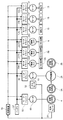
図3は、芝刈り車両1の概略構成をブロック図で示している。図3において、図1に示した構成に相当する構成については同一の符号を付している。芝刈り車両1は、エンジン24と、油圧ポンプ25A,25Bと、発電機26とを備える。油圧ポンプ25A,25Bおよび発電機26は、エンジン24により駆動される。油圧ポンプ25Aは、油圧モータ28を駆動し、この油圧モータ28は、前輪3A,3Bを駆動する。前輪3Aと前輪3Bとの間には、差動機構29が備えられる。芝刈り車両1の旋回時の内外輪の差動は、差動機構29により吸収される。また、油圧ポンプ25Bは、油圧シリンダ30を駆動し、この油圧シリンダ30は、後輪4の舵角を変化させる。油圧シリンダ30は、オペレータにより回転操作されるステアリングホイール8の回転量に応じた駆動量で駆動され、後輪4の舵角は、油圧シリンダ30の駆動量に応じて変化する。つまり、芝刈り車両1は、図4に示すステアリング機構8Aを有する。このステアリング機構8Aは、いわゆるパワーステアリング機構となっている。
FIG. 3 is a block diagram showing a schematic configuration of the
ここで、図4を参照して、ステアリング機構8Aの概略の構成を説明する。ステアリング機構8Aは、油圧ポンプ25Bと、油圧シリンダ30と、ステアリングユニット8Bと、舵取り腕8Cと、作動油タンク8Dとを有する。ステアリングホイール8を回転させることにより、ステアリングホイール8の回転角度に比例した体積の作動油が油圧シリンダ30に送られシリンダロッド30Aを伸縮させる。そして、シリンダロッド30Aの伸縮により舵取り腕8Cが作動(押し引き)され後輪4の舵角が変化する。なお、油圧シリンダ30のシリンダロッド30Aの伸縮により舵取り腕8Cが作動させられるため、ステアリングホイール8の回転角と後輪4の舵角とは比例していない。
Here, a schematic configuration of the
図3に示すように、エンジン24により駆動される発電機26により発電された電力はバッテリ27に蓄電される。発電機26は、交流電流を直流電流に変換する図示を省略するAC/DC変換器を備えている。モータ17,17,17および電動シリンダ22A,22B,22Cは、バッテリ27の電力により駆動される。各モータ17により前側芝刈り機構5A,5Bおよび後側芝刈り機構6の各回転刃15が回転させられることより、芝の刈り取りが行われる。芝刈り車両1は、エンジン24により油圧ポンプ25Aおよび油圧モータ28を駆動し前輪3A,3Bを回転させて走行し、また、バッテリ27によりモータ17を駆動し回転刃15を回転させ芝の刈り取りを行う、いわゆるハイブリッド型の芝刈り車両として構成されている。
As shown in FIG. 3, the electric power generated by the
芝刈り車両1は、後輪4の舵角を検出する舵角センサ31と、芝刈り車両1の車速を検出する車速センサ32と、各モータ17を駆動するモータドライバ17A,17B,17Cと、電動シリンダ22A,22B,22Cをそれぞれ駆動するモータドライバ22A1,22B1,22C1と、芝刈り車両1の動作を制御する制御装置33を備えている。
The
舵角センサ31は、たとえば、ロータリポジションセンサを用いることができる。つまり、後輪4の舵角に応じて回転するローターの回転に伴う電気抵抗値を測定し、この測定結果に基づき後輪4の舵角を検出することができる。また、車速センサ32は、たとえば、ロータリエンコーダを用いることができる。つまり、油圧モータ28の単位時間当たりの回転数をロータリエンコーダにより測定し、この測定結果に基づき芝刈り車両1の走行速度(車速)を検出することができる。
As the
制御装置33は、マイクロコンピュータやメモリ等を備え、表示装置23から入力される操作指示に基づき、前側芝刈り機構5A,5Bおよび後側芝刈り機構6の駆動、芝刈り車両1の走行等の諸動作を制御する。また、制御装置33は、前進アクセルペダル9の踏み込み量等に応じてエンジン24の回転速度(単位時間当たりの回転数)等を制御する。さらに、制御装置33は、芝刈り車両1あるいは路面の傾斜を検出する図示を省略する傾斜センサからの検出信号に基づき、モータドライバ22A1,22B1,22C1を介して電動シリンダ22A,22B,22Cを駆動する。また、制御装置33は、後述するように、舵角センサ31および車速センサ32の信号に基づき、モータドライバ17A,17B,17Cを介して各モータ17の回転速度(単位時間当たりの回転数)を制御する。すなわち、回転刃15の回転速度(単位時間当たりの回転数)を制御する。また、制御装置33は、芝刈り車両1の状態を示す情報(例えば、車速、回転刃15の回転速度を示す情報等)を表示装置23に表示する。
The
(回転刃15の回転速度の制御)
図5を参照しながら、回転刃15の回転速度の制御について説明する。制御装置33は、以下に説明するように、舵角センサ31により検出される後輪4の舵角θと、車速センサ32により検出される芝刈り車両1の車速とに基づいて、前側芝刈り機構5A,5Bおよび後側芝刈り機構6に備えられる各モータ17の回転速度を制御する。これにより、芝刈り車両1は、芝刈り車両1の旋回時の各芝刈り機構5A,5B,6同士の芝の刈り取り状態を均一にすることができる。
(Control of the rotational speed of the rotary blade 15)
Control of the rotational speed of the
図5に示すように、後輪4が舵角θのとき、駆動輪である前輪3Aと前輪3Bとの間の中心Mの旋回半径R1、前輪3Aと前輪3Bとのうち内輪側の旋回半径R2、外輪側の旋回半径R3、および後輪4の旋回半径R4は、次の式(1)(2)(3)(4)として示される。
R1=((W+r・cosθ)/tanθ)+r・sinθ ・・・ (1)
R2=((W+r・cosθ)/tanθ)+r・sinθ−T/2 ・・・ (2)
R3=((W+r・cosθ)/tanθ)+r・sinθ+T/2 ・・・ (3)
R4=((W+r・cosθ)/sinθ) ・・・ (4)
W:ホイールベース
T:トレッド
r:後輪4の操舵の回転中心と、後輪4の回転中心とのオフセット
(芝刈り車両1の直進安定性を向上させるために、後輪4の操舵の回転中心は、後輪4の回転中心よりも前方に偏倚させられている。)
As shown in FIG. 5, when the
R 1 = ((W + r · cos θ) / tan θ) + r · sin θ (1)
R 2 = ((W + r · cos θ) / tan θ) + r · sin θ−T / 2 (2)
R 3 = ((W + r · cos θ) / tan θ) + r · sin θ + T / 2 (3)
R 4 = ((W + r · cos θ) / sin θ) (4)
W: Wheel base T: Tread r: Offset between the rotation center of the steering of the
図6に示すように、座標系の原点Oを前輪3Aと前輪3Bとの中心Mにとり、芝刈り車両1の前後方向にX軸(前方を負、後方を正)、左右方向にY軸(旋回方向内側を負、外側を正)を取る。このとき、芝刈り車両1の旋回中心P0の位置座標(X0,Y0)は、次の式(5)として示される。

そして、前側芝刈り機構5A,5Bおよび後側芝刈り機構6の各回転刃15の中心の位置を中心位置Piとし、中心位置Piの位置座標(Xi,Yi)とするとき、中心位置Piの旋回中心P0に対する旋回半径Priは、次の式(6)として示される。
Pr2:前側芝刈り機構5Bの回転刃15の中心位置P2(X2,Y2)の旋回半径
Pr3:後側芝刈り機構6の回転刃15の中心位置P3(X3,Y3)の旋回半径
When the position of the center of each
中心位置P1(X1,Y1)、中心位置P2(X2,Y2)、中心位置P3(X3,Y3)は、それぞれ芝刈り車両1の設計により定められる既知の位置座標である。
The center position P 1 (X 1 , Y 1 ), the center position P 2 (X 2 , Y 2 ), and the center position P 3 (X 3 , Y 3 ) are respectively known positions determined by the design of the
芝刈り車両1の設計上の値が、たとえば、
W(ホイールベース)=1255mm
T(トレッド)=1046.7mm
r(後輪4の操舵角中心と回転中心のオフセット)=30mm
P1(X1,Y1)=P1(−453mm,−484.08mm)
P2(X2,Y2)=P2(−453mm,484.08mm)
P3(X3,Y3)=P3(699.5mm,0mm)
であるとき、後輪4の舵角θのときのR1に対する、Pr1、Pr2、Pr3の比は、図7に示すグラフのようになる。たとえば、後輪4の舵角θ=30度のときは、R1:Pr1:Pr2:Pr3=1:0.81:1.23:1.05となる。
The design value of the
W (Wheelbase) = 1255mm
T (tread) = 1046.7 mm
r (the offset between the steering angle center and the rotation center of the rear wheel 4) = 30 mm
P 1 (X 1 , Y 1 ) = P 1 (−453 mm, −484.08 mm)
P 2 (X 2 , Y 2 ) = P 2 (−453 mm, 484.08 mm)
P 3 (X 3 , Y 3 ) = P 3 (699.5 mm, 0 mm)
, The ratio of Pr 1 , Pr 2 , Pr 3 to R 1 at the steering angle θ of the
この場合、制御装置33は、回転刃15の次に説明する「所定の回転速度」に対して、前側芝刈り機構5A、前側芝刈り機構5Bおよび後側芝刈り機構6のそれぞれの回転刃15の回転速度を、0.81:1.23:1.05倍で回転させる。
In this case, the
「所定の回転速度」とは、芝刈り車両1の車速に応じて定められる回転速度(単位時間当たりの回転数)である。芝刈り車両1の車速に対して回転刃15の回転速度が遅いと、芝の刈り取りピッチが大きくなり刈り残しが発生し易くなる。そのため、芝の刈り残しを減少させ、好適に芝を刈ることができるように、制御装置33は、車速が速くなるほど回転刃15の回転速度が速くなるように回転刃15の回転を制御する。つまり、芝刈り車両1においては、車速に応じて好適に芝刈りを行うことができるように、回転刃15の回転速度が定められる。
The “predetermined rotation speed” is a rotation speed (the number of rotations per unit time) determined according to the vehicle speed of the
芝刈り車両1の車速に対して好適に芝を刈り取ることができる回転速度を、車速毎に「所定の回転速度」として、制御装置33のメモリにテーブルとして記憶させておき、制御装置33は、このテーブルに基づき回転刃15の回転速度を制御することができる。また、芝刈り車両1の車速と、車速に対して好適に芝を刈り取ることができる回転刃15の回転速度との関係を示す計算式を制御装置33のメモリに記憶しておき、制御装置33は、この計算式に基づき回転刃15の回転速度を制御してもよい。
The rotational speed at which the
制御装置33は、車速センサ32の測定結果に基づき車速を測定し、車速に応じて回転刃15の所定の回転速度を決定すると共に、各芝刈り機構の回転刃15を、所定の回転速度に対して、回転刃15の中心位置P1,P2,P3の旋回半径の比に応じた回転速度で回転させる。これにより、芝刈り車両1は、旋回時にも、芝の刈り残しが発生しないようにしながら各芝刈り機構同士の芝の刈り取り状態を均一にすることができる。
The
なお、設計値である、W、T、r、P1(X1,Y1)、P2(X2,Y2)およびP3(X3,Y3)についても予めメモリ部に記憶されている。制御装置33は、舵角センサ31により検出される後輪4の舵角θと各設計値に基づき式(1)から(6)を用いて、芝刈り車両1の旋回半径R1と、各回転刃15の中心位置P1,P2,P3の旋回半径Pr1,Pr2,Pr3とを算出し、芝刈り車両1の旋回半径R1と中心位置P1,P2,P3の旋回半径Pr1,Pr2,Pr3との比を算出する。そして、制御装置33は、所定の回転速度と、R1:Pr1:Pr2:Pr3とに基づいて各芝刈り機構のモータドライバ17A,17B,17Cを制御して回転刃15の回転速度を制御する。
The design values W, T, r, P 1 (X 1 , Y 1 ), P 2 (X 2 , Y 2 ) and P 3 (X 3 , Y 3 ) are also stored in advance in the memory unit. ing. The
なお、舵角θが0度の場合は、芝刈り車両1は直進状態であり、各芝刈り機構の回転刃15に旋回速度の差は生じていないので、制御装置33は、各芝刈り機構の回転刃15を所定の回転速度で回転させる。
When the steering angle θ is 0 degree, the
上述したように、芝刈り車両1は、回転駆動手段としてのモータ17によって回転される回転刃15を有する複数の前側芝刈り機構5A、前側芝刈り機構5B、後側芝刈り機構6と、芝刈り車両1の操舵輪としての後輪4の舵角θを検出する舵角検出手段としての舵角センサ31と、舵角センサ31により検出された舵角θに基づいて、前側芝刈り機構5A、前側芝刈り機構5Bおよび後側芝刈り機構6それぞれについて回転刃15の回転速度を制御する制御装置33とを備えている。
As described above, the
このように、操舵輪である後輪4の舵角θにより、前側芝刈り機構5A,5Bおよび後側芝刈り機構6の各回転刃15の回転を制御することで、芝刈り車両1の旋回時の芝刈り機構同士の芝の刈り取り状態をより均一にすることができる。これに対し、上述の特許文献1に示すように、ステアリングホイール8の回転角(切れ角)に応じて、前側芝刈り機構5A,5Bおよび後側芝刈り機構6の各回転刃15の回転を制御する手段も考えられる。しかしながら、後輪4が路面から受ける衝撃が直接ステアリングホイール8に伝わらないようにしたり、ステアリングホイール8の操作が敏感に後輪4の舵角に伝わらないようにする等の観点から、一般に、ステアリングホイール8の回転と後輪4の舵角とには遊びが設けられている。つまり、ステアリングホイール8の回転と、各芝刈り機構の旋回半径とが正確に(1対1で)対応していない虞がある。そのため、ステアリングホイール8の回転角に応じて、各芝刈り機構の回転刃15の回転速度を制御した場合には、回転刃15の回転速度を各芝刈り機構の旋回半径(Pr1,Pr2,Pr3)に正確に(1対1で)対応させることができない虞がある。したがって、芝刈り車両1の旋回時の各芝刈り機構同士の芝の刈り取り状態の均一化を十分に図ることができない虞がある。
Thus, the turning of the
これに対し、後輪4の舵角θに基づいて各芝刈り機の回転刃15の回転速度を制御した場合には、後輪4の舵角θと、各回転刃15の中心位置P1,P2,P3の旋回半径Pr1,Pr2,Pr3とを1対1で対応させ易くなる。このため、各回転刃15の中心位置P1,P2,P3の旋回半径Pr1,Pr2,Pr3を回転刃15の回転速度に正確に反映することができる。したがって、芝刈り車両1の旋回時の各芝刈り機構同士の芝の刈り取り状態の均一化を好適に図ることができる。
On the other hand, when the rotational speed of the
また、制御装置33は、後輪4の舵角θに基づいて、複数の芝刈り機構である前側芝刈り機構5A,5Bおよび後側芝刈り機構6それぞれに備えられる回転刃15の所定位置を中心位置Piとし、この中心位置Piの旋回半径Pr1、Pr2、Pr3と、芝刈り車両1の所定位置を前輪3Aと前輪3Bとの中心Mとし、この中心Mの旋回半径R1との比率を算出し、この比率に基づいて各芝刈り機構の回転刃15の回転速度をそれぞれ制御することとしている。
Further, the
このように、芝刈り車両1の所定位置(中心M)の旋回半径R1と各芝刈り機構の回転刃15の中心位置Piの旋回半径Pr1、Pr2、Pr3との比率に基づいて、各芝刈り機構の回転刃15の回転速度をそれぞれ制御することにより、各回転刃15の中心位置Piの旋回速度に応じた回転刃15の回転速度の制御の精度の向上を図ることができる。これにより、芝刈り車両1の旋回時の前側芝刈り機構5A,5Bおよび後側芝刈り機構6同士の芝の刈り取り状態の均一化を一層好適なものとすることができる。
Thus, based on the ratio between the turning radius Pr 1, Pr 2, Pr 3 of the center position P i of the
芝刈り車両1は、前輪3Aと前輪3Bとの対称中心の位置である中心Mを芝刈り車両1を所定位置とし、中心Mの旋回半径R1と各芝刈り機構の旋回半径Pr1、Pr2、Pr3との比率に基づいて、各芝刈り機構の回転刃15の回転速度をそれぞれ制御している。
制御装置33は、回転刃15の所定の回転速度を芝刈り車両1の車速に基づいて決定する。旋回時の芝刈り車両1は、旋回の内側と外側とで旋回速度が異なる。したがって、旋回半径R1は、芝刈り車両1の中で、芝刈り車両1の直進時の車速に対してできるだけ変化の少ない位置とすることが好ましい。中心Mは、前輪3Aと前輪3Bとの対称中心位置であり、旋回状態にある芝刈り車両1の中で、芝刈り車両1の直進時の車速に対して車速の変化の少ない位置である。そこで、中心Mを所定位置とし、この所定位置(中心M)の旋回半径R1に対する各芝刈り機構の回転刃の所定位置の旋回半径Pr1、Pr2、Pr3との比率に基づいて各芝刈り機構の回転刃15の回転速度をそれぞれ制御することで、各芝刈り機構同士の芝の刈り取り状態をより一層均一化にすることができる。
The
なお、所定位置としては、駆動輪である前輪3Aと前輪3Bとの間の中心Mの他、芝刈り車両1の重心としてもよい。
The predetermined position may be the center of gravity of the
図8は、芝刈り車両1の変形例の構成を示す図である。芝刈り車両1は、図8に示すように、前輪3A,3Bの駆動および後輪4の操舵力のアシストをエンジンの駆動力に行う構成に替えて、前輪3A,3Bの駆動をモータドライバ50により駆動されるモータ51により行い、さらに後輪4の操舵力のアシストをモータドライバ52により駆動されるモータ53により行う電動式の車両として構成としてもよい。芝刈り車両1を電動式の車両として構成した場合にも、上述の実施の形態で説明した芝刈り車両1と同様に、各芝刈り機構の回転刃15の回転速度の制御を行うことができる。
FIG. 8 is a diagram illustrating a configuration of a modified example of the
上述の実施の形態およびその変形例では、3輪で走行する構成の芝刈り車両1を示したが、4輪で走行する構成としてもよい。芝刈り車両1が4輪で走行し、前後いずれか一方が駆動輪となる構成の場合、所定位置は、駆動輪の中心が好ましい。また、前後輪ともに駆動輪となる場合は、4輪の対称中心位置を芝刈り車両1の所定位置とすることが好ましい。
In the above-described embodiment and its modification, the
上述の実施の形態およびその変形例では、回転刃15における所定位置を回転刃15の回転軸の中心位置としている。しかしながら、芝刈り車両1の旋回時においては、同一の回転刃15についても旋回速度が旋回の内側と外側とで異なる。したがって、回転刃15における所定位置は、回転刃15の回転軸の中心位置よりも旋回方向の外側の位置としてもよい。このようにすることで、回転刃15における所定位置の旋回半径が大きくなる。上述したように、回転刃15の回転速度は、該所定位置の旋回半径の大きさに基づいて設定される。そのため、回転刃15の回転速度を速くすることができる。回転刃15の回転速度を速くすることで、各回転刃15の回転軸方向について、芝の刈り残しの発生を減少させることができる。
In the above-described embodiment and its modification, the predetermined position on the
しかしながら、回転刃15における所定位置を回転刃15の回転軸の中心位置よりも旋回方向の外側の位置とする場合には、旋回方向毎に回転刃15における所定位置を変更する必要がある。これに対し、回転刃15における所定位置を回転軸の中心位置とすることで、該所定位置の旋回半径を算出演算処理の負荷を低減することができる。
However, when the predetermined position on the
上述の実施の形態およびその変形例では、前輪3A,3Bの回転に基づいて車速を検出する構成としているが、後輪4の回転に基づいて車速を検出してもよい。この場合には、前輪3Aと前輪3Bとの中心Mの旋回半径R1と、後輪4の旋回半径R4とに基づき、中心Mの移動速度に変換し、これを芝刈り車両1の車速とすることが好ましい。
In the above-described embodiment and its modification, the vehicle speed is detected based on the rotation of the
1 … 芝刈り車両
4 … 後輪(操舵輪)
5A,5B … 前側芝刈り機構(芝刈り機構)
6 … 後側芝刈り機構(芝刈り機構)
15 … 回転刃
17 … モータ(回転駆動手段)
31 … 舵角センサ(舵角検出手段)
33 … 制御装置(制御手段)
θ … 舵角
P1,P2,P3 … 回転刃の中心位置(回転刃の所定位置)
M … 中心(芝刈り車両の所定位置)
1 ...
5A, 5B ... Front lawn mowing mechanism (turf mowing mechanism)
6 ... Rear lawn mowing mechanism (lawn mowing mechanism)
15 ...
31 ... Rudder angle sensor (steering angle detection means)
33 ... Control device (control means)
θ: Steering angle P 1 , P 2 , P 3 ... Center position of the rotary blade (predetermined position of the rotary blade)
M ... Center (predetermined position of lawn mower)
Claims (2)
前記芝刈り車両の操舵輪の舵角を検出する舵角検出手段と、
前記舵角検出手段により検出された舵角に基づいて、前記複数の芝刈り機構それぞれについて前記回転刃の回転速度を制御する制御手段と、
を有し、
前記複数の芝刈り機構は、前記芝刈り車両の直進時の進行方向の左右に設けられる両側芝刈り機構と、前記芝刈り車両の直進時の進行方向の左右方向の中央に設けられる中央芝刈り機構とを少なくとも含み、
前記制御手段は、前記舵角に基づいて、前記複数の芝刈り機構のそれぞれに備えられる前記回転刃の所定位置の旋回半径と、前記芝刈り車両の所定位置の旋回半径との比率を算出し、この比率に基づいて、前記芝刈り車両の車速に基づいて決定される前記複数の芝刈り機構の回転刃の回転速度をそれぞれ制御する、
ことを特徴とする芝刈り車両。 In a lawnmower vehicle comprising a plurality of lawnmower mechanisms having a rotary blade rotated by a rotation drive means,
Rudder angle detection means for detecting the rudder angle of the steered wheels of the lawn mower vehicle;
Control means for controlling the rotational speed of the rotary blade for each of the plurality of lawn mowing mechanisms based on the rudder angle detected by the rudder angle detection means;
Have
The plurality of lawn mowing mechanisms include a double-sided lawn mowing mechanism provided on the left and right of the direction of travel of the lawn mower vehicle and a central lawn mower provided on the center of the direction of travel of the lawn mower vehicle when traveling straight. Including at least a mechanism,
The control means calculates, based on the rudder angle, a ratio between a turning radius at a predetermined position of the rotary blade provided in each of the plurality of lawn mowing mechanisms and a turning radius at a predetermined position of the lawn mowing vehicle. , Based on this ratio, respectively, to control the rotation speed of the rotary blades of the plurality of lawn mowing mechanisms determined based on the vehicle speed of the lawn mowing vehicle ,
A lawnmower vehicle characterized by that.
前記芝刈り車両の所定位置は、駆動輪となる車輪同士の対称中心位置とする、
ことを特徴とする芝刈り車両。 The lawnmower vehicle according to claim 1 ,
The predetermined position of the lawn mowing vehicle is a symmetrical center position of wheels that serve as driving wheels.
A lawnmower vehicle characterized by that.
Priority Applications (1)
| Application Number | Priority Date | Filing Date | Title |
|---|---|---|---|
| JP2014063805A JP6210916B2 (en) | 2014-03-26 | 2014-03-26 | Lawn mower |
Applications Claiming Priority (1)
| Application Number | Priority Date | Filing Date | Title |
|---|---|---|---|
| JP2014063805A JP6210916B2 (en) | 2014-03-26 | 2014-03-26 | Lawn mower |
Publications (2)
| Publication Number | Publication Date |
|---|---|
| JP2015181473A JP2015181473A (en) | 2015-10-22 |
| JP6210916B2 true JP6210916B2 (en) | 2017-10-11 |
Family
ID=54348788
Family Applications (1)
| Application Number | Title | Priority Date | Filing Date |
|---|---|---|---|
| JP2014063805A Active JP6210916B2 (en) | 2014-03-26 | 2014-03-26 | Lawn mower |
Country Status (1)
| Country | Link |
|---|---|
| JP (1) | JP6210916B2 (en) |
Families Citing this family (1)
| Publication number | Priority date | Publication date | Assignee | Title |
|---|---|---|---|---|
| WO2019180850A1 (en) * | 2018-03-20 | 2019-09-26 | 本田技研工業株式会社 | Work machine |
Family Cites Families (11)
| Publication number | Priority date | Publication date | Assignee | Title |
|---|---|---|---|---|
| JPS61188421U (en) * | 1985-05-16 | 1986-11-25 | ||
| JPS63254918A (en) * | 1987-04-13 | 1988-10-21 | 井関農機株式会社 | Mower apparatus of riding lawn mower |
| US5406778A (en) * | 1994-02-03 | 1995-04-18 | Ransomes America Corporation | Electric drive riding greens mower |
| JPH07222508A (en) * | 1994-02-10 | 1995-08-22 | Fuji Heavy Ind Ltd | Self-traveling working vehicle |
| JPH09243372A (en) * | 1996-03-11 | 1997-09-19 | Hitachi Ltd | Method for controlling operation of traveling working machine |
| JP3329209B2 (en) * | 1996-09-27 | 2002-09-30 | 株式会社豊田自動織機 | Steering angle correction device for power steering device and vehicle |
| JP3164012B2 (en) * | 1997-04-15 | 2001-05-08 | 株式会社豊田自動織機製作所 | Industrial vehicle steering angle correction device and industrial vehicle |
| JP3721704B2 (en) * | 1997-04-17 | 2005-11-30 | 株式会社豊田自動織機 | Industrial vehicle swing control device |
| JP2000185534A (en) * | 1998-12-21 | 2000-07-04 | Komatsu Forklift Co Ltd | Axle fixing control device for industrial vehicle |
| JP4842335B2 (en) * | 2009-02-12 | 2011-12-21 | 日立建機株式会社 | Electric vehicle turning assist device |
| JP5658880B2 (en) * | 2010-01-13 | 2015-01-28 | 株式会社Ihi | Lawn mower |
-
2014
- 2014-03-26 JP JP2014063805A patent/JP6210916B2/en active Active
Also Published As
| Publication number | Publication date |
|---|---|
| JP2015181473A (en) | 2015-10-22 |
Similar Documents
| Publication | Publication Date | Title |
|---|---|---|
| JP6321970B2 (en) | Lawn mower | |
| JP6479627B2 (en) | Electric work vehicle | |
| JP2008168869A (en) | Riding lawn mower | |
| JP5658880B2 (en) | Lawn mower | |
| US10967903B2 (en) | Electrically powered work vehicle | |
| JP2021040603A (en) | Lawn mowing vehicle with automatic traveling function | |
| WO2018097033A1 (en) | Work machine | |
| JP2008168870A (en) | Riding lawn mower | |
| JP6382761B2 (en) | Self-propelled vehicle | |
| JP2018082683A (en) | Working machine | |
| JP6802852B2 (en) | Work vehicle | |
| JP5699509B2 (en) | Riding lawn mower vehicle and control method thereof | |
| JP5521941B2 (en) | Riding lawn mower vehicle and control method thereof | |
| JP6210916B2 (en) | Lawn mower | |
| JP5771356B2 (en) | Riding lawn mower | |
| JP5678549B2 (en) | Riding lawn mower vehicle and control method thereof | |
| JP4107592B2 (en) | Rolling control device for work equipment | |
| JP5751465B2 (en) | Riding lawn mower vehicle and control method thereof | |
| JP5752479B2 (en) | Riding lawn mower vehicle and control method thereof | |
| JP2012070554A (en) | Riding type lawn mowing vehicle and control method thereof | |
| JP4107590B2 (en) | Rolling control device for work equipment | |
| JP2019216670A (en) | Work vehicle | |
| US20240383279A1 (en) | Tool device and steerable-wheel assembly | |
| WO2024100957A1 (en) | System and method for controlling work machine | |
| US20250034834A1 (en) | Systems and methods of providing ride control with a power machine |
Legal Events
| Date | Code | Title | Description |
|---|---|---|---|
| A621 | Written request for application examination |
Free format text: JAPANESE INTERMEDIATE CODE: A621 Effective date: 20161011 |
|
| A977 | Report on retrieval |
Free format text: JAPANESE INTERMEDIATE CODE: A971007 Effective date: 20170523 |
|
| A131 | Notification of reasons for refusal |
Free format text: JAPANESE INTERMEDIATE CODE: A131 Effective date: 20170606 |
|
| A521 | Request for written amendment filed |
Free format text: JAPANESE INTERMEDIATE CODE: A523 Effective date: 20170727 |
|
| TRDD | Decision of grant or rejection written | ||
| A01 | Written decision to grant a patent or to grant a registration (utility model) |
Free format text: JAPANESE INTERMEDIATE CODE: A01 Effective date: 20170905 |
|
| A61 | First payment of annual fees (during grant procedure) |
Free format text: JAPANESE INTERMEDIATE CODE: A61 Effective date: 20170912 |
|
| R150 | Certificate of patent or registration of utility model |
Ref document number: 6210916 Country of ref document: JP Free format text: JAPANESE INTERMEDIATE CODE: R150 |
|
| S531 | Written request for registration of change of domicile |
Free format text: JAPANESE INTERMEDIATE CODE: R313531 |
|
| S533 | Written request for registration of change of name |
Free format text: JAPANESE INTERMEDIATE CODE: R313533 |
|
| R350 | Written notification of registration of transfer |
Free format text: JAPANESE INTERMEDIATE CODE: R350 |
|
| RD02 | Notification of acceptance of power of attorney |
Free format text: JAPANESE INTERMEDIATE CODE: R3D02 |
|
| R250 | Receipt of annual fees |
Free format text: JAPANESE INTERMEDIATE CODE: R250 |
|
| R250 | Receipt of annual fees |
Free format text: JAPANESE INTERMEDIATE CODE: R250 |
|
| R250 | Receipt of annual fees |
Free format text: JAPANESE INTERMEDIATE CODE: R250 |
|
| R250 | Receipt of annual fees |
Free format text: JAPANESE INTERMEDIATE CODE: R250 |
|
| R250 | Receipt of annual fees |
Free format text: JAPANESE INTERMEDIATE CODE: R250 |