US5304932A - Apparatus and method for shielding MRI RF antennae from the effect of surrounding objects - Google Patents
Apparatus and method for shielding MRI RF antennae from the effect of surrounding objects Download PDFInfo
- Publication number
- US5304932A US5304932A US07/608,807 US60880790A US5304932A US 5304932 A US5304932 A US 5304932A US 60880790 A US60880790 A US 60880790A US 5304932 A US5304932 A US 5304932A
- Authority
- US
- United States
- Prior art keywords
- mri
- coil
- shield
- static magnet
- gradient magnetic
- Prior art date
- Legal status (The legal status is an assumption and is not a legal conclusion. Google has not performed a legal analysis and makes no representation as to the accuracy of the status listed.)
- Expired - Lifetime
Links
- 238000000034 method Methods 0.000 title claims description 23
- 230000003068 static effect Effects 0.000 claims abstract description 59
- 238000003384 imaging method Methods 0.000 claims description 20
- 239000011888 foil Substances 0.000 claims description 9
- 239000004593 Epoxy Substances 0.000 claims description 8
- 229910052782 aluminium Inorganic materials 0.000 claims description 7
- XAGFODPZIPBFFR-UHFFFAOYSA-N aluminium Chemical compound [Al] XAGFODPZIPBFFR-UHFFFAOYSA-N 0.000 claims description 7
- 239000011152 fibreglass Substances 0.000 claims description 4
- 229910052751 metal Inorganic materials 0.000 claims 2
- 239000002184 metal Substances 0.000 claims 2
- 239000004020 conductor Substances 0.000 abstract description 10
- 230000004907 flux Effects 0.000 abstract description 3
- 238000002595 magnetic resonance imaging Methods 0.000 description 27
- 238000003475 lamination Methods 0.000 description 6
- 230000008569 process Effects 0.000 description 5
- 238000005481 NMR spectroscopy Methods 0.000 description 4
- 238000010521 absorption reaction Methods 0.000 description 4
- 238000013461 design Methods 0.000 description 4
- RYGMFSIKBFXOCR-UHFFFAOYSA-N Copper Chemical compound [Cu] RYGMFSIKBFXOCR-UHFFFAOYSA-N 0.000 description 2
- 229910052802 copper Inorganic materials 0.000 description 2
- 239000010949 copper Substances 0.000 description 2
- 238000009826 distribution Methods 0.000 description 2
- 239000000463 material Substances 0.000 description 2
- 238000012986 modification Methods 0.000 description 2
- 230000004048 modification Effects 0.000 description 2
- 230000000007 visual effect Effects 0.000 description 2
- 238000013459 approach Methods 0.000 description 1
- 230000005540 biological transmission Effects 0.000 description 1
- 238000000701 chemical imaging Methods 0.000 description 1
- 230000006835 compression Effects 0.000 description 1
- 238000007906 compression Methods 0.000 description 1
- 238000010276 construction Methods 0.000 description 1
- 230000008878 coupling Effects 0.000 description 1
- 238000010168 coupling process Methods 0.000 description 1
- 238000005859 coupling reaction Methods 0.000 description 1
- 230000001419 dependent effect Effects 0.000 description 1
- 238000004519 manufacturing process Methods 0.000 description 1
- 230000007246 mechanism Effects 0.000 description 1
- 230000035699 permeability Effects 0.000 description 1
- 238000012216 screening Methods 0.000 description 1
- 238000012360 testing method Methods 0.000 description 1
- 230000007723 transport mechanism Effects 0.000 description 1
Images
Classifications
-
- G—PHYSICS
- G01—MEASURING; TESTING
- G01R—MEASURING ELECTRIC VARIABLES; MEASURING MAGNETIC VARIABLES
- G01R33/00—Arrangements or instruments for measuring magnetic variables
- G01R33/20—Arrangements or instruments for measuring magnetic variables involving magnetic resonance
- G01R33/28—Details of apparatus provided for in groups G01R33/44 - G01R33/64
- G01R33/42—Screening
- G01R33/421—Screening of main or gradient magnetic field
-
- G—PHYSICS
- G01—MEASURING; TESTING
- G01R—MEASURING ELECTRIC VARIABLES; MEASURING MAGNETIC VARIABLES
- G01R33/00—Arrangements or instruments for measuring magnetic variables
- G01R33/20—Arrangements or instruments for measuring magnetic variables involving magnetic resonance
- G01R33/28—Details of apparatus provided for in groups G01R33/44 - G01R33/64
- G01R33/42—Screening
- G01R33/422—Screening of the radio frequency field
Definitions
- This invention relates to the field of magnetic resonance imaging (MRI) utilizing nuclear magnetic resonance (NMR) phenomena. It is particularly directed toward the shielding of RF coils in an MRI system from extraneous noise sources.
- MRI magnetic resonance imaging
- NMR nuclear magnetic resonance
- Magnetic resonance spectroscopic imaging (MRSI) systems are also known and are hereinafter intended to be included within the terminology "MRI” system.
- MRI systems typically include a relatively massive static magnet structure for creating a static magnetic field B o .
- the static magnet may include a solenoidal cryogenic super-conducting electromagnet or may be of a permanent magnet design.
- Whatever form of static magnetic is used, it is also typically used in conjunction with a plurality of magnetic gradient coils which are sequentially pulsed to create a sequence of controlled gradients in the static magnetic field during an MRI data gathering sequence.
- Such controlled sequential gradients are effectuated throughout a patient imaging volume that also is coupled to at least one MRI RF coil.
- MRI RF signals of suitable frequencies are transmitted into the imaging volume and NMR responsive RF signals are then received from the imaging volume via one or more RF coils or antennae.
- Information encoded within the frequency and phase parameters of the received RF signals is then processed to form visual images representing the distribution of NMR nuclei within a cross-section or volume of the patient within the imaging volume of the MRI system.
- the generation of high quality MRI depends strongly upon the quality of the RF receiving antenna used in the data gathering procedure. There are some RF noise sources inherently present in the process (e.g., within the patient body being imaged) but it is important that care be taken to avoid introduction of any additional unnecessary noise sources into the received RF signals.
- the third category of possible RF power absorption is in the static magnet and/or other structures surrounding the RF coil.
- the degree of RF power absorbed in the static magnet or other surrounding structures can be strongly dependent upon the details of magnet design and construction. For example, as above-noted, it has been discovered that adding laminations to the static magnet pole tip (as described in related copending application Ser. No. 07/546,112), now abandoned greatly increases RF power absorption in the static magnet structure.
- the static magnet structure itself may be a source of significant power absorption and therefore a source of significant RF noise during the receiving process.
- a receiving coil having a Q of approximately 800 when located outside the magnet may have its Q cut to approximately one-half that value when situated in its operational position between the laminated magnetic pole pieces.
- the traditional approach to limitation of eddy currents in a conductive member is to create laminations or cuts in the conductor.
- the so-called “skin depth" ⁇ of alternating current signals within a conductor is a function of the conductivity ⁇ , the magnetic permeability ⁇ , the frequency ⁇ by the relation: ##EQU1##
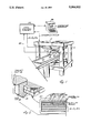
- FIG. 1 is a schematic view of an exemplary MRI system having laminated static magnet pole tips in an "open access" type of MRI system and also incorporating an ultra-thin RF shield conductor between the RF coils and the static magnet laminated pole tips; and
- FIG. 2 is an exploded schematic view of the RF shield and associated structures used in the exemplary embodiment of FIG. 1.
- the static magnet structure includes massive magnetic circuit components such as pillars 10 sandwiched between members 12 and supporting pole pieces 14 of a permanent magnet structure.
- Laminated pole tips 16 are disposed above and below the image volume 18 and one or more RF coil structures 20 are RF coupled to the image volume 18 as well.
- Suitable patient transport mechanism 22 is employed for moving a human patient into and out of the image volume 18 as should be apparent.
- the apparatus so far described may typically be located in a shielded room of an MRI facility.
- the remainder of the MRI control system 24 is typically located with an operator console 26 so as to properly control and operate the entire MR system by causing predetermined sequences of magnetic gradient pulses G x , G y and G z as well as RF transmissions and receptions and any other necessary controls so as to collect MRI data, process it and produce visual images (either on the operator console 26 or equivalent digital data which can be transferred to other display units or other media for display or filming).
- the pole tip 16 of the exemplary embodiment includes mutually insulated laminations 30, 32 within an annular frame 34. Although the mechanism may not be completely understood at this time, it has been noted that such laminations 30, 32 greatly increase RF noise in the MRI system.
- Flat gradient coils G x , G y , G z are typically encapsulated within a vacuum cast epoxy covering 40 and located within the approximately one meter diameter pole tip area so as to generate the necessary sequence of gradients in the main magnetic field during an MRI sequence.
- a pair of 0.001 inch thick aluminum foil RF shield layers 42, 44 are sandwiched together between fiberglass mats (approximately 1/16 inch thick before compression) 50, 52 and disposed between the magnetic gradient coils and the laminated pole tip within the vacuum cast epoxy covering 40.
- this positioning of the RF shield members 42, 44 leaves the RF coil structures 20 coupled to the gradient coils, it is presently preferred because it locates the shield member as far away as possible from the RF antenna structures. Since my experience reveals that the gradient coils do not produce significant noise artifact, leaving them coupled to the RF coil (at least in the exemplary embodiment), does not appear to cause any significant problem.
- the Q of the RF coils was approximately halved when located in the image volume area.
- the Q of the RF coil was only lowered by about 2.5% (e.g., a Q of 800 was reduced to a Q of about 780).
- the RF shield is effective in substantially decoupling the RF coil from outer extraneous noise sources in the system such as the laminated pole tip of the static magnet structure in the exemplary embodiment.
- the two sheets of aluminum foil 42, 44 may have some epoxy between them at the edges due to the vacuum cast process, they are assumed to be in substantial electrical contact with one another throughout.
- the RF shield foils 42, 44 are electrically isolated from all other MRI structures, it is believed that such conductive layers could well be electrically grounded within the MR system.
- the RF shield of the exemplary embodiment does not shield the RF coils from all other MRI structures, it will be appreciated that it does substantially shield the RF coils from the laminated pole tip structures (which appear to be a principal source of Johnson noise during the RF reception process in this particular exemplary embodiment).
- the skin depth thickness in copper is approximately 0.0015 inch.
- copper sheets of conventional thickness e.g., more than three skin depths
- aluminum foil is used. Since a commercially available foil thickness is 0.001 inch, and since the skin depth at 2.7 megahertz in aluminum is on the order of 0.002 inch, two sheets of such foil are used.
Landscapes
- Physics & Mathematics (AREA)
- Health & Medical Sciences (AREA)
- Epidemiology (AREA)
- Condensed Matter Physics & Semiconductors (AREA)
- General Physics & Mathematics (AREA)
- Magnetic Resonance Imaging Apparatus (AREA)
Abstract
An MRI RF coil is shielded from extraneous noise sources using an extremely thin conductive shield interposed between the RF coil and the static magnetic structure of an MRI system. To control eddy currents induced in such conductor by the changing magnetic flux of MRI gradient coils, the RF shield conductor thickness is less than three skin depths at the MRI RF operating frequencies of the RF coil. Preferably, the RF shield conductor thickness is on the order of only one skin depth or less.
Description
This invention relates to the field of magnetic resonance imaging (MRI) utilizing nuclear magnetic resonance (NMR) phenomena. It is particularly directed toward the shielding of RF coils in an MRI system from extraneous noise sources.
This patent application is related to commonly assigned issued U.S. Pat. No. 4,829,252--Kaufman and to commonly assigned copending U.S. patent application Ser. No. 07/546,112 filed Jul. 2, 1990 naming Kaufman et al as inventors and entitled "MRI Magnet with Robust Laminated Magnetic Circuit Member and Method of Making Same," now abandoned. The entire contents of this related issued patent and of pending U.S. patent application are hereby incorporated by reference into this application.
MRI systems from many different sources are now well-known and commercially available. Magnetic resonance spectroscopic imaging (MRSI) systems are also known and are hereinafter intended to be included within the terminology "MRI" system.
MRI systems typically include a relatively massive static magnet structure for creating a static magnetic field Bo. The static magnet may include a solenoidal cryogenic super-conducting electromagnet or may be of a permanent magnet design. Whatever form of static magnetic is used, it is also typically used in conjunction with a plurality of magnetic gradient coils which are sequentially pulsed to create a sequence of controlled gradients in the static magnetic field during an MRI data gathering sequence. Such controlled sequential gradients are effectuated throughout a patient imaging volume that also is coupled to at least one MRI RF coil. As a part of a typical MRI data gathering sequence, MRI RF signals of suitable frequencies are transmitted into the imaging volume and NMR responsive RF signals are then received from the imaging volume via one or more RF coils or antennae. Information encoded within the frequency and phase parameters of the received RF signals is then processed to form visual images representing the distribution of NMR nuclei within a cross-section or volume of the patient within the imaging volume of the MRI system.
The above-noted related U.S. Pat. No. 4,829,252 describes an MRI system using permanent magnets with open access to the patient image volume and is particularly suited for use in the exemplary embodiment of this invention. To reduce imaging artifacts caused by eddy currents induced in the static magnet structure from changing magnetic flux of the gradient coils, the above-referenced related copending application proposes lamination of the static magnet pole tips. As will be described below, such lamination has been discovered to increase RF noise sources and thus to provide increased need for its shielding from the MRI RF coil(s).
The generation of high quality MRI depends strongly upon the quality of the RF receiving antenna used in the data gathering procedure. There are some RF noise sources inherently present in the process (e.g., within the patient body being imaged) but it is important that care be taken to avoid introduction of any additional unnecessary noise sources into the received RF signals.
Recalling the reciprocity theorem, it will be recognized that one way to assess sources of received RF noise is to measure the power absorbed when the RF antenna is used as a transmitter. Anything which absorbs power in the transmitting mode will also be a source of noise when the same antenna is used as a receiver.
There are three general sources of such power absorption. One is in the antenna itself and that is typically minimized through careful design and use of high quality materials. Another non-avoidable source of noise is in the patient tissues being imaged (albeit surface coils or other techniques can be use for minimized coupling to areas of the patient not actually of image interest). The third category of possible RF power absorption (and therefore a noise source during the RF reception mode) is in the static magnet and/or other structures surrounding the RF coil.
The degree of RF power absorbed in the static magnet or other surrounding structures can be strongly dependent upon the details of magnet design and construction. For example, as above-noted, it has been discovered that adding laminations to the static magnet pole tip (as described in related copending application Ser. No. 07/546,112), now abandoned greatly increases RF power absorption in the static magnet structure.
Generally located closest to the RF receiving antenna is the set of magnetic gradient coils and their associated structure. Although this is a possible source of power loss due to the presence of conducting wires throughout the gradient coil structures, experience has indicated that such losses are typically not an excessive problem.
However, as briefly noted above, experience has now indicated that the static magnet structure itself (typically located outwardly of the gradient coil structures) may be a source of significant power absorption and therefore a source of significant RF noise during the receiving process. For example, when a laminated pole tip structure for the static magnet is used, it has been noted that a receiving coil having a Q of approximately 800 when located outside the magnet may have its Q cut to approximately one-half that value when situated in its operational position between the laminated magnetic pole pieces.
Of course it is well-known in the literature that one can shield an RF antenna from external influences by surrounding the antenna with a good conductor. However, in the context of MRI, such shielding itself produces still further potential imaging artifacts since a conductive surface gives rise to eddy currents generated by changing magnetic flux of the gradient coils (the magnetic field of such eddy currents in turn causing undesirable changes in the magnetic field distribution in the imaging volume). Better conductivity of the shield makes it a better shield--but also causes such eddy currents to take longer to decay to zero and therefore causes greater potential imaging artifact.
The traditional approach to limitation of eddy currents in a conductive member is to create laminations or cuts in the conductor.
However, we have discovered that better resulting coil Q can be achieved simultaneously with effective RF coil shielding and control of unwanted eddy currents by using an extremely thin sheet of conductive material as the RF shield. If the shielding layer is thin enough, then induced eddy currents from the gradient pulses can be very small while still retaining sufficient RF shielding from extraneous noise sources (e.g., from the laminated static magnet pole tips).
As is well known, the so-called "skin depth" δ of alternating current signals within a conductor is a function of the conductivity σ, the magnetic permeability μ, the frequency ω by the relation: ##EQU1##
Conventional practice heretofore for RF shield designs is to use a shield conductor thickness which is at least three skin depths (anything thicker than that being substantially unused anyway at the RF frequency of interest since about 97% of all current flows in the first three skin depths).
However, we have discovered that by purposefully making the RF shield conductor thickness less than three skin depths, one can still achieve effective RF shielding for MRI purposes while simultaneously controlling gradient coil eddy current artifacts.
These as well as other features and advantages of this invention will be better appreciated by careful study of the following detailed description of a presently preferred exemplary embodiment of this invention taken in conjunction with the accompanying drawings of which:
FIG. 1 is a schematic view of an exemplary MRI system having laminated static magnet pole tips in an "open access" type of MRI system and also incorporating an ultra-thin RF shield conductor between the RF coils and the static magnet laminated pole tips; and
FIG. 2 is an exploded schematic view of the RF shield and associated structures used in the exemplary embodiment of FIG. 1.
An exemplary MRI system employing this invention is schematically depicted at FIG. 1. Here, the static magnet structure includes massive magnetic circuit components such as pillars 10 sandwiched between members 12 and supporting pole pieces 14 of a permanent magnet structure. Laminated pole tips 16 are disposed above and below the image volume 18 and one or more RF coil structures 20 are RF coupled to the image volume 18 as well. Suitable patient transport mechanism 22 is employed for moving a human patient into and out of the image volume 18 as should be apparent.
The apparatus so far described may typically be located in a shielded room of an MRI facility. In an adjacent control room, the remainder of the MRI control system 24 is typically located with an operator console 26 so as to properly control and operate the entire MR system by causing predetermined sequences of magnetic gradient pulses Gx, Gy and Gz as well as RF transmissions and receptions and any other necessary controls so as to collect MRI data, process it and produce visual images (either on the operator console 26 or equivalent digital data which can be transferred to other display units or other media for display or filming).
As depicted in FIG. 2, the pole tip 16 of the exemplary embodiment includes mutually insulated laminations 30, 32 within an annular frame 34. Although the mechanism may not be completely understood at this time, it has been noted that such laminations 30, 32 greatly increase RF noise in the MRI system.
Flat gradient coils Gx, Gy, Gz are typically encapsulated within a vacuum cast epoxy covering 40 and located within the approximately one meter diameter pole tip area so as to generate the necessary sequence of gradients in the main magnetic field during an MRI sequence. In the exemplary embodiment, a pair of 0.001 inch thick aluminum foil RF shield layers 42, 44 are sandwiched together between fiberglass mats (approximately 1/16 inch thick before compression) 50, 52 and disposed between the magnetic gradient coils and the laminated pole tip within the vacuum cast epoxy covering 40. Although, this positioning of the RF shield members 42, 44 leaves the RF coil structures 20 coupled to the gradient coils, it is presently preferred because it locates the shield member as far away as possible from the RF antenna structures. Since my experience reveals that the gradient coils do not produce significant noise artifact, leaving them coupled to the RF coil (at least in the exemplary embodiment), does not appear to cause any significant problem.
As previously mentioned, with a laminated pole tip structure as in the exemplary embodiment, without any RF shielding the Q of the RF coils was approximately halved when located in the image volume area. However, by including an RF shield between the gradient coils and the laminated pole tip, the Q of the RF coil was only lowered by about 2.5% (e.g., a Q of 800 was reduced to a Q of about 780). Accordingly, the RF shield is effective in substantially decoupling the RF coil from outer extraneous noise sources in the system such as the laminated pole tip of the static magnet structure in the exemplary embodiment.
Although the two sheets of aluminum foil 42, 44 may have some epoxy between them at the edges due to the vacuum cast process, they are assumed to be in substantial electrical contact with one another throughout. Furthermore, although in the exemplary embodiment the RF shield foils 42, 44 are electrically isolated from all other MRI structures, it is believed that such conductive layers could well be electrically grounded within the MR system.
Although the RF shield of the exemplary embodiment does not shield the RF coils from all other MRI structures, it will be appreciated that it does substantially shield the RF coils from the laminated pole tip structures (which appear to be a principal source of Johnson noise during the RF reception process in this particular exemplary embodiment).
At the RF frequencies used in the exemplary embodiment (e.g., approximately 2.7 megahertz), the skin depth thickness in copper is approximately 0.0015 inch. I have found that copper sheets of conventional thickness (e.g., more than three skin depths) produces unacceptably large eddy current MRI artifacts. However, I have also discovered that using a material substantially less than even one skin depth thick still maintains essentially fully effective RF screening while simultaneously having sufficiently reduced conductivity for induced gradient field eddy currents so as to effectively suppress artifact from this source.
Based on present tests, it appears that an RF screen approximately 0.5 to 0.75 skin depth thickness provides an effective RF screen while producing gradient pulsed induced eddy currents which persist for only approximately one millisecond. Since any currents with such relatively fast decay times are not typically too serious a hindrance to MRI, this has been found to provide an acceptable compromise.
In the exemplary embodiment, aluminum foil is used. Since a commercially available foil thickness is 0.001 inch, and since the skin depth at 2.7 megahertz in aluminum is on the order of 0.002 inch, two sheets of such foil are used.
While only one exemplary embodiment of this invention has been described in detail, those skilled in the art will recognize that many variations and modifications of this embodiment may be made while still retaining many of the novel features and advantages of this invention. Accordingly, all such variations and modifications are intended to be included within the scope of the appended claims.
Claims (18)
1. In an MRI system having a static magnet and a set of gradient magnetic coils used to create a sequence of controlled MRI magnetic fields within an MRI imaging volume that is coupled to at least one MRI RF coil, the improvement comprising:
an RF shield interposed between said RF coil and said static magnet, said shield including a conductive layer of thickness less than three skin depths at the MRI RF operating frequencies of said RF coil thereby shielding the RF coil from the static magnet while also limiting eddy currents induced in the shield by the gradient magnetic coils.
2. An MRI system as in claim 1 wherein said RF shield is electrically insulated from all other structures in the MRI system.
3. An MRI system as in claim 1 wherein said conductive layer is a continuous metal film.
4. In an MRI system having a static magnet and a set of gradient magnetic coils used to create a sequence of controlled MRI magnetic fields within an MRI imaging volume that is coupled to at least one MRI RF coil, the improvement comprising:
an RF shield interposed between said RF coil and said static magnet, said shield including a conductive layer of thickness less than three skin depths at the MRI RF operating frequencies of said RF coil thereby shielding the RF coil from the static magnet while also limiting eddy currents induced in the shield by the gradient magnetic coils, and
wherein said RF shield comprises a plurality of conductive layers, each layer being of thickness less than one skin depth at the MRI operating frequencies of said RF coil.
5. In an MRI system having a static magnet and a set of gradient magnetic coils used to create a sequence of controlled MRI magnetic fields within an MRI imaging volume that is coupled to at least one MRI RF coil, the improvement comprising:
an RF shield interposed between said RF coil and said static magnet, said shield including a conductive layer of thickness less than three skin depths at the MRI RF operating frequencies of said RF coil thereby shielding the RF coil from the static magnet while also limiting eddy currents induced in the shield by the gradient magnetic coils, and
wherein said RF shield is interposed between said static magnet and said set of gradient magnetic coils.
6. In an MRI system having a static magnet and a set of gradient magnetic coils used to create a sequence of controlled MRI magnetic fields within an MRI imaging volume that is coupled to at least one MRI RF coil, the improvement comprising:
an RF shield interposed between said RF coil and said static magnet, said shield including a conductive layer of thickness less than three skin depths at the MRI RF operating frequencies of said RF coil thereby shielding the RF coil from the static magnet while also limiting eddy currents induced in the shield by the gradient magnetic coils, and
wherein said static magnet includes laminated pole tips to reduce eddy currents induced therein by the gradient magnetic coils.
7. In an MRI system having a static magnet and a set of gradient magnetic coils used to create a sequence of controlled MRI magnetic fields within an MRI imaging volume that is coupled to at least one MRI RF coil, the improvement comprising:
an RF shield interposed between said RF coil and said static magnet, said shield including a conductive layer of thickness less than three skin depths at the MRI RF operating frequencies of said RF coil thereby shielding the RF coil from the static magnet while also limiting eddy currents induced in the shield by the gradient magnetic coils, and
wherein said shield comprises a pair of 0.001 inch thick aluminum foils sandwiched together between fiberglass mats in a cast epoxy covering.
8. In an MRI system having a static magnet and a set of gradient magnetic coils used to create a sequence of controlled MRI magnetic fields within an MRI imaging volume that is coupled to at least one MRI RF coil, the improvement comprising:
an RF shield interposed between said RF coil and said static magnet, said shield including a conductive layer of thickness less than three skin depths at the MRI RF operating frequencies of said RF coil thereby shielding the RF coil from the static magnet while also limiting eddy currents induced in the shield by the gradient magnetic coils, and
wherein said shield comprises a pair of 0.001 inch thick aluminum foils sandwiched together between fiberglass mats in a cast epoxy covering.
9. AN MRI structure as in claim 8 wherein said gradient magnetic coils, mutually insulated from one another, are also included within said cast epoxy covering.
10. A method for shielding an MRI RF coil in an MRI system having a static magnet and a set of gradient magnetic coils used to create a sequence of controlled MRI magnetic fields within an MRI imaging volume that is coupled to at least one MRI RF coil, the method comprising:
interposing an RF shield between said RF coil and said static magnet, said shield including a conductive layer of thickness less than three skin depths at the MRI operating frequencies of said RF coil thereby shielding the RF coil from the static magnet while also limiting eddy currents induced in the shield by the gradient magnetic coils.
11. A method as in claim 10 wherein said RF shield is electrically insulated from all other structures in the MRI system.
12. A method as in claim 10 wherein said conductive layer is a continuous metal film.
13. A method for shielding an MRI RF coil in an MRI system having a static magnet and a set of gradient magnetic coils used to create a sequence of controlled MRI magnetic fields within an MRI imaging volume that is coupled to at least one MRI RF coil, the method comprising:
interposing an RF shield between said RF coil and said static magnet, said shield including a conductive layer of thickness less than three skin depths at the MRI operating frequencies of said RF coil thereby shielding the RF coil from the static magnet while also limiting eddy currents induced in the shield by the gradient magnetic coils, and
wherein said RF shield comprises a plurality of conductive layers, each layer being of thickness than one skin depth at the MRI operating frequencies of said RF coil.
14. A method for shielding an MRI RF coil in an MRI system having a static magnet and a set of gradient magnetic coils used to create a sequence of controlled MRI magnetic fields within an MRI imaging volume that is coupled to at least one MRI RF coil, the method comprising:
interposing an RF shield between said RF coil and said static magnet, said shield including a conductive layer of thickness less than three skin depths at the MRI operating frequencies of said RF coil thereby shielding the RF coil from the static magnet while also limiting eddy currents induced in the shield by the gradient magnetic coils, and
wherein said RF shield is interposed between said static magnet and said set of gradient magnetic coils.
15. A method for shielding an MRI RF coil in an MRI system having a static magnet and a set of gradient magnetic coils used to create a sequence of controlled MRI magnetic fields within an MRI imaging volume that is coupled to at least one MRI RF coil, the method comprising:
interposing an RF shield between said RF coil and said static magnet, said shield including a conductive layer of thickness less than three skin depths at the MRI operating frequencies of said RF coil thereby shielding the RF coil from the static magnet while also limiting eddy currents induced in the shield by the gradient magnetic coils, and
wherein said static magnet includes laminated pole tips to reduce eddy currents induced therein by the gradient magnetic coils.
16. A method for shielding an MRI RF coil in an MRI system having a static magnet and a set of gradient magnetic coils used to create a sequence of controlled MRI magnetic fields within an MRI imaging volume that is coupled to at least one MRI RF coil, the method comprising:
interposing an RF shield between said RF coil and said static magnet, said shield including a conductive layer of thickness less than three skin depths at the MRI operating frequencies of said RF coil thereby shielding the RF coil from the static magnet while also limiting eddy currents induced in the shield by the gradient magnetic coils, and
wherein said RF shield comprises a conductive layer of thickness less than one skin depth at the MRI operating frequencies of said RF coil.
17. A method for shielding an MRI RF coil in an MRI system having a static magnet and a set of gradient magnetic coils used to create a sequence of controlled MRI magnetic fields within an MRI imaging volume that is coupled to at least one MRI RF coil, the method comprising:
interposing an RF shield between said RF coil and said static magnet, said shield including a conductive layer of thickness less than three skin depths at the MRI operating frequencies of said RF coil thereby shielding the RF coil from the static magnet while also limiting eddy currents induced in the shield by the gradient magnetic coils, and
wherein said shield comprises a pair of 0.001 inch thick aluminum foils sandwiched together between fiberglass mats in a cast epoxy covering.
18. A method as in claim 17 wherein said gradient magnetic coils, mutually insulated from one another, are also included within said cast epoxy covering.
Priority Applications (1)
| Application Number | Priority Date | Filing Date | Title |
|---|---|---|---|
| US07/608,807 US5304932A (en) | 1990-11-05 | 1990-11-05 | Apparatus and method for shielding MRI RF antennae from the effect of surrounding objects |
Applications Claiming Priority (1)
| Application Number | Priority Date | Filing Date | Title |
|---|---|---|---|
| US07/608,807 US5304932A (en) | 1990-11-05 | 1990-11-05 | Apparatus and method for shielding MRI RF antennae from the effect of surrounding objects |
Publications (1)
| Publication Number | Publication Date |
|---|---|
| US5304932A true US5304932A (en) | 1994-04-19 |
Family
ID=24438094
Family Applications (1)
| Application Number | Title | Priority Date | Filing Date |
|---|---|---|---|
| US07/608,807 Expired - Lifetime US5304932A (en) | 1990-11-05 | 1990-11-05 | Apparatus and method for shielding MRI RF antennae from the effect of surrounding objects |
Country Status (1)
| Country | Link |
|---|---|
| US (1) | US5304932A (en) |
Cited By (43)
| Publication number | Priority date | Publication date | Assignee | Title |
|---|---|---|---|---|
| US5381122A (en) * | 1994-01-14 | 1995-01-10 | General Electric Company | Open MRI magnet having a support structure |
| US5389909A (en) * | 1993-11-08 | 1995-02-14 | General Electric Company | Open architecture magnetic resonance imaging passively shimmed superconducting magnet assembly |
| US5467017A (en) * | 1992-09-30 | 1995-11-14 | Siemens Aktiengesellschaft | Antenna arrangement for a nuclear magnetic resonance apparatus |
| GB2295675A (en) * | 1994-12-01 | 1996-06-05 | Univ California | Four-post MRI magnet with RF screens |
| US5583439A (en) * | 1993-01-19 | 1996-12-10 | Fonar Corporation | Eddy current control in NMR imaging systems |
| US5675256A (en) * | 1995-07-04 | 1997-10-07 | Picker International, Inc. | Magnetic resonance methods and apparatus |
| US5886596A (en) * | 1993-08-06 | 1999-03-23 | Uab Research Foundation | Radio frequency volume coils for imaging and spectroscopy |
| US5939883A (en) * | 1996-07-17 | 1999-08-17 | Fonar Corporation | Magnetic resonance imaging excitation and reception methods and apparatus |
| US6028429A (en) * | 1996-07-17 | 2000-02-22 | Fonar Corporation | Composite MRI antenna with reduced stray capacitance |
| US6107974A (en) * | 1998-10-21 | 2000-08-22 | Fonar Corporation | Apparatus and method of generating an RF field |
| US6201394B1 (en) | 1992-12-18 | 2001-03-13 | Fonar Corporation | MRI apparatus |
| EP1089303A1 (en) * | 1999-09-28 | 2001-04-04 | DenkenSeiki Re. In. Corp. | Isolation transformers |
| US6335623B1 (en) | 1992-12-18 | 2002-01-01 | Fonar Corporation | MRI apparatus |
| US6437571B1 (en) | 1997-11-21 | 2002-08-20 | Fonar Corporation | MRI apparatus |
| US6538440B2 (en) | 2001-06-20 | 2003-03-25 | Ge Medical Systems Global Technology Co., Llc | Non-conductive long wave thermal radiation shield |
| US20030144718A1 (en) * | 2002-01-29 | 2003-07-31 | Zeijlemaker Volkert A. | Method and apparatus for shielding coating for MRI resistant electrode systems |
| US6633161B1 (en) | 1999-05-21 | 2003-10-14 | The General Hospital Corporation | RF coil for imaging system |
| US20040012391A1 (en) * | 1999-05-21 | 2004-01-22 | Vaughan J. T. | Radio frequency gradient and shim coil |
| US20040021467A1 (en) * | 2002-05-02 | 2004-02-05 | Ludwig Eberler | Magnetic resonance tomography apparatus with vacuum cast or vacuum die cast body coil |
| US20040027128A1 (en) * | 2000-07-31 | 2004-02-12 | Regents Of The University Of Minnesota | Radio frequency magnetic field unit |
| US20040186374A1 (en) * | 2003-03-18 | 2004-09-23 | Luigi Satragno | Magnetic resonance imaging apparatus |
| US6879157B1 (en) | 2000-11-22 | 2005-04-12 | Fonar Corporation | Ferromagnetic frame with laminated carbon steel |
| US20050264290A1 (en) * | 2003-02-21 | 2005-12-01 | Tsunemoto Suzuki | RF shield and MRI system |
| US20060197530A1 (en) * | 2004-09-27 | 2006-09-07 | Fonar Corporation | Magnetic resonance imaging system, apparatus and associated methods |
| US7127802B1 (en) * | 1997-11-21 | 2006-10-31 | Fonar Corporation | Method of fabricating a composite plate |
| US20090219025A1 (en) * | 2008-02-29 | 2009-09-03 | Masahiro Fujimoto | Coil and mri system |
| US7701209B1 (en) | 2001-10-05 | 2010-04-20 | Fonar Corporation | Coils for horizontal field magnetic resonance imaging |
| US7710117B2 (en) | 2004-05-07 | 2010-05-04 | Regents Of The University Of Minnesota | Multi-current elements for magnetic resonance radio frequency coils |
| US7906966B1 (en) | 2001-10-05 | 2011-03-15 | Fonar Corporation | Quadrature foot coil antenna for magnetic resonance imaging |
| CN102890254A (en) * | 2011-07-20 | 2013-01-23 | 西门子公司 | Control of gradient coils with inductive coupling taken into consideration |
| US8401615B1 (en) | 2004-11-12 | 2013-03-19 | Fonar Corporation | Planar coil flexion fixture for magnetic resonance imaging and use thereof |
| DE202013104361U1 (en) | 2013-09-24 | 2013-11-14 | Aspect Imaging Ltd. | Means for reducing the electromagnetic energy propagation from a magnetic bore of an MRD to the external environment surrounding the magnet, and vice versa |
| US8599215B1 (en) | 2008-05-07 | 2013-12-03 | Fonar Corporation | Method, apparatus and system for joining image volume data |
| WO2014141245A1 (en) | 2013-03-11 | 2014-09-18 | Aspect Imaging Ltd. | Means and methods for reducing the electromagnetic energy propagation from an mrd's magnet-bore to the outer environment surrounding said magnet, and vice versa |
| DE202015102451U1 (en) | 2014-05-13 | 2015-06-01 | Aspect Imaging Ltd. | Size adjustable protective and immobilizing cuffs for MRI devices |
| US9386939B1 (en) | 2007-05-10 | 2016-07-12 | Fonar Corporation | Magnetic resonance imaging of the spine to detect scoliosis |
| US9417301B2 (en) | 2010-08-25 | 2016-08-16 | Koninklijke Philips N.V. | RF shield for MRI comprising conductive coating as shielding material |
| US9766310B1 (en) | 2013-03-13 | 2017-09-19 | Fonar Corporation | Method and apparatus for magnetic resonance imaging of the cranio-cervical junction |
| US10078122B2 (en) | 2014-03-09 | 2018-09-18 | Aspect Imaging Ltd. | MRI RF shielding jacket |
| US10386432B2 (en) | 2013-12-18 | 2019-08-20 | Aspect Imaging Ltd. | Radiofrequency shielding conduit in a door or a doorframe of a magnetic resonance imaging room |
| US10401452B2 (en) | 2017-04-28 | 2019-09-03 | Aspect Imaging Ltd. | System for reduction of a magnetic fringe field of a magnetic resonance imaging device |
| US11002809B2 (en) | 2014-05-13 | 2021-05-11 | Aspect Imaging Ltd. | Protective and immobilizing sleeves with sensors, and methods for reducing the effect of object movement during MRI scanning |
| US11029378B2 (en) | 2016-12-14 | 2021-06-08 | Aspect Imaging Ltd. | Extendable radiofrequency shield for magnetic resonance imaging device |
Citations (7)
| Publication number | Priority date | Publication date | Assignee | Title |
|---|---|---|---|---|
| US4642569A (en) * | 1983-12-16 | 1987-02-10 | General Electric Company | Shield for decoupling RF and gradient coils in an NMR apparatus |
| US4785246A (en) * | 1985-06-26 | 1988-11-15 | Kabushiki Kaisha Toshiba | Magnetic resonance imaging apparatus |
| US4829252A (en) * | 1987-10-28 | 1989-05-09 | The Regents Of The University Of California | MRI system with open access to patient image volume |
| US4871969A (en) * | 1988-12-22 | 1989-10-03 | General Electric Company | RF shield for RF coil contained within gradient coils of NMR imaging device |
| US4920316A (en) * | 1989-03-30 | 1990-04-24 | Siemens Medical Systems, Inc. | Method and apparatus for reducing base field shifts in a magnetic resonance device due to pulsed magnetic field gradients |
| US4980641A (en) * | 1989-08-11 | 1990-12-25 | General Atomics | Method and apparatus of reducing magnetic hysteresis in MRI systems |
| US5083085A (en) * | 1989-03-26 | 1992-01-21 | Elscint Ltd. | Compact shielded gradient coil system |
-
1990
- 1990-11-05 US US07/608,807 patent/US5304932A/en not_active Expired - Lifetime
Patent Citations (7)
| Publication number | Priority date | Publication date | Assignee | Title |
|---|---|---|---|---|
| US4642569A (en) * | 1983-12-16 | 1987-02-10 | General Electric Company | Shield for decoupling RF and gradient coils in an NMR apparatus |
| US4785246A (en) * | 1985-06-26 | 1988-11-15 | Kabushiki Kaisha Toshiba | Magnetic resonance imaging apparatus |
| US4829252A (en) * | 1987-10-28 | 1989-05-09 | The Regents Of The University Of California | MRI system with open access to patient image volume |
| US4871969A (en) * | 1988-12-22 | 1989-10-03 | General Electric Company | RF shield for RF coil contained within gradient coils of NMR imaging device |
| US5083085A (en) * | 1989-03-26 | 1992-01-21 | Elscint Ltd. | Compact shielded gradient coil system |
| US4920316A (en) * | 1989-03-30 | 1990-04-24 | Siemens Medical Systems, Inc. | Method and apparatus for reducing base field shifts in a magnetic resonance device due to pulsed magnetic field gradients |
| US4980641A (en) * | 1989-08-11 | 1990-12-25 | General Atomics | Method and apparatus of reducing magnetic hysteresis in MRI systems |
Cited By (82)
| Publication number | Priority date | Publication date | Assignee | Title |
|---|---|---|---|---|
| US5467017A (en) * | 1992-09-30 | 1995-11-14 | Siemens Aktiengesellschaft | Antenna arrangement for a nuclear magnetic resonance apparatus |
| US6201394B1 (en) | 1992-12-18 | 2001-03-13 | Fonar Corporation | MRI apparatus |
| US6848170B1 (en) | 1992-12-18 | 2005-02-01 | Fonar Corporation | Method for fabricating a ferromagnetic plate |
| US6496007B1 (en) | 1992-12-18 | 2002-12-17 | Fonar Corporation | MRI apparatus |
| US6469508B1 (en) | 1992-12-18 | 2002-10-22 | Fonar Corporation | MRI apparatus |
| US6445186B1 (en) | 1992-12-18 | 2002-09-03 | Fonar Corporation | MRI apparatus |
| US6369571B1 (en) | 1992-12-18 | 2002-04-09 | Fonar Corporation | MRI apparatus |
| US6335623B1 (en) | 1992-12-18 | 2002-01-01 | Fonar Corporation | MRI apparatus |
| US6208145B1 (en) | 1992-12-18 | 2001-03-27 | Fonar Corporation | MRI apparatus |
| US5592089A (en) * | 1993-01-19 | 1997-01-07 | Fonar Corporation | Eddy current control in NMR imaging system |
| US5583439A (en) * | 1993-01-19 | 1996-12-10 | Fonar Corporation | Eddy current control in NMR imaging systems |
| US5886596A (en) * | 1993-08-06 | 1999-03-23 | Uab Research Foundation | Radio frequency volume coils for imaging and spectroscopy |
| US5389909A (en) * | 1993-11-08 | 1995-02-14 | General Electric Company | Open architecture magnetic resonance imaging passively shimmed superconducting magnet assembly |
| US5381122A (en) * | 1994-01-14 | 1995-01-10 | General Electric Company | Open MRI magnet having a support structure |
| US5539314A (en) * | 1994-12-01 | 1996-07-23 | The Regents Of The University Of California | RF shield for four-post vertical field magnet used for MRI |
| GB2295675A (en) * | 1994-12-01 | 1996-06-05 | Univ California | Four-post MRI magnet with RF screens |
| US5675256A (en) * | 1995-07-04 | 1997-10-07 | Picker International, Inc. | Magnetic resonance methods and apparatus |
| US6229310B1 (en) | 1996-07-17 | 2001-05-08 | Fonar Corporation | Magnetic resonance imaging excitation and reception methods and apparatus |
| US5939883A (en) * | 1996-07-17 | 1999-08-17 | Fonar Corporation | Magnetic resonance imaging excitation and reception methods and apparatus |
| US6028429A (en) * | 1996-07-17 | 2000-02-22 | Fonar Corporation | Composite MRI antenna with reduced stray capacitance |
| US6437571B1 (en) | 1997-11-21 | 2002-08-20 | Fonar Corporation | MRI apparatus |
| US6617852B1 (en) | 1997-11-21 | 2003-09-09 | Fonar Corporation | MRI apparatus |
| US7127802B1 (en) * | 1997-11-21 | 2006-10-31 | Fonar Corporation | Method of fabricating a composite plate |
| US6541973B1 (en) | 1997-11-21 | 2003-04-01 | Fonar Corporation | MRI apparatus |
| US6107974A (en) * | 1998-10-21 | 2000-08-22 | Fonar Corporation | Apparatus and method of generating an RF field |
| US20060033501A1 (en) * | 1999-05-21 | 2006-02-16 | The General Hospital Corporation D/B/A Massachusetts General Hospital | RF coil for imaging system |
| US20070007964A1 (en) * | 1999-05-21 | 2007-01-11 | The General Hospital Corporation D/B/A Massachusetts General Hospital | RF coil for imaging system |
| US20040012391A1 (en) * | 1999-05-21 | 2004-01-22 | Vaughan J. T. | Radio frequency gradient and shim coil |
| US6633161B1 (en) | 1999-05-21 | 2003-10-14 | The General Hospital Corporation | RF coil for imaging system |
| US7268554B2 (en) | 1999-05-21 | 2007-09-11 | The General Hospital Corporation | RF coil for imaging system |
| US20070247160A1 (en) * | 1999-05-21 | 2007-10-25 | The General Hospital Corporation D/B/A Massachusetts General Hospital | Rf coil for imaging system |
| US7598739B2 (en) | 1999-05-21 | 2009-10-06 | Regents Of The University Of Minnesota | Radio frequency gradient, shim and parallel imaging coil |
| EP1089303A1 (en) * | 1999-09-28 | 2001-04-04 | DenkenSeiki Re. In. Corp. | Isolation transformers |
| US7893693B2 (en) | 2000-07-31 | 2011-02-22 | Regents Of The University Of Minnesota | Assymetric radio frequency magnetic line array |
| US20040027128A1 (en) * | 2000-07-31 | 2004-02-12 | Regents Of The University Of Minnesota | Radio frequency magnetic field unit |
| US6958607B2 (en) | 2000-07-31 | 2005-10-25 | Regents Of The University Of Minnesota | Assymetric radio frequency transmission line array |
| US20060255806A1 (en) * | 2000-07-31 | 2006-11-16 | Regents Of The University Of Minnesota | Assymetric radio frequency magnetic line array |
| US20060001426A1 (en) * | 2000-07-31 | 2006-01-05 | Regents Of The University Of Minnesota | Assymetric radio frequency magnetic line array |
| US6879157B1 (en) | 2000-11-22 | 2005-04-12 | Fonar Corporation | Ferromagnetic frame with laminated carbon steel |
| US6538440B2 (en) | 2001-06-20 | 2003-03-25 | Ge Medical Systems Global Technology Co., Llc | Non-conductive long wave thermal radiation shield |
| US7906966B1 (en) | 2001-10-05 | 2011-03-15 | Fonar Corporation | Quadrature foot coil antenna for magnetic resonance imaging |
| US8055326B1 (en) | 2001-10-05 | 2011-11-08 | Fonar Corporation | Coils for horizontal field magnetic resonance imaging |
| US7701209B1 (en) | 2001-10-05 | 2010-04-20 | Fonar Corporation | Coils for horizontal field magnetic resonance imaging |
| US20030144718A1 (en) * | 2002-01-29 | 2003-07-31 | Zeijlemaker Volkert A. | Method and apparatus for shielding coating for MRI resistant electrode systems |
| US6825665B2 (en) | 2002-05-02 | 2004-11-30 | Siemens Aktiengesellschaft | Magnetic resonance tomography apparatus with vacuum cast or vacuum die cast body coil |
| US20040021467A1 (en) * | 2002-05-02 | 2004-02-05 | Ludwig Eberler | Magnetic resonance tomography apparatus with vacuum cast or vacuum die cast body coil |
| GB2393787A (en) * | 2002-05-02 | 2004-04-07 | Siemens Ag | A body coil for a magnetic resonance imaging apparatus |
| GB2393787B (en) * | 2002-05-02 | 2005-06-22 | Siemens Ag | A body coil for a magnetic resonance tomography apparatus |
| US7157911B2 (en) * | 2003-02-21 | 2007-01-02 | Ge Medical Systems Global Technology Company, Llc | RF shield and MRI system |
| US20050264290A1 (en) * | 2003-02-21 | 2005-12-01 | Tsunemoto Suzuki | RF shield and MRI system |
| US20040186374A1 (en) * | 2003-03-18 | 2004-09-23 | Luigi Satragno | Magnetic resonance imaging apparatus |
| US8755863B2 (en) | 2003-03-18 | 2014-06-17 | Esaote S.P.A. | Magnetic resonance imaging apparatus |
| US8064984B2 (en) | 2003-03-18 | 2011-11-22 | Esaote S.P.A. | Magnetic resonance imaging apparatus |
| US8761861B2 (en) | 2003-03-18 | 2014-06-24 | Esaote S.P.A. | Magnetic resonance imaging method including coordinated rotation of patient table and magnetic structure |
| US7710117B2 (en) | 2004-05-07 | 2010-05-04 | Regents Of The University Of Minnesota | Multi-current elements for magnetic resonance radio frequency coils |
| US20090256573A1 (en) * | 2004-09-27 | 2009-10-15 | Fonar Corporation | Magnetic resonance imaging system, apparatus and associated methods |
| US7812607B2 (en) | 2004-09-27 | 2010-10-12 | Fonar Corporation | Magnetic resonance imaging system, apparatus and associated methods |
| US7560928B2 (en) | 2004-09-27 | 2009-07-14 | Fonar Corporation | Magnetic resonance imaging system, apparatus and associated methods |
| US20060197530A1 (en) * | 2004-09-27 | 2006-09-07 | Fonar Corporation | Magnetic resonance imaging system, apparatus and associated methods |
| US8401615B1 (en) | 2004-11-12 | 2013-03-19 | Fonar Corporation | Planar coil flexion fixture for magnetic resonance imaging and use thereof |
| US9386939B1 (en) | 2007-05-10 | 2016-07-12 | Fonar Corporation | Magnetic resonance imaging of the spine to detect scoliosis |
| US9730610B1 (en) | 2007-05-10 | 2017-08-15 | Fonar Corporation | Magnetic resonance imaging of the spine to detect scoliosis |
| US20090219025A1 (en) * | 2008-02-29 | 2009-09-03 | Masahiro Fujimoto | Coil and mri system |
| US8030929B2 (en) | 2008-02-29 | 2011-10-04 | Ge Medical Systems Global Technology Company, Llc | Coil and MRI system |
| US8599215B1 (en) | 2008-05-07 | 2013-12-03 | Fonar Corporation | Method, apparatus and system for joining image volume data |
| US9417301B2 (en) | 2010-08-25 | 2016-08-16 | Koninklijke Philips N.V. | RF shield for MRI comprising conductive coating as shielding material |
| CN102890254A (en) * | 2011-07-20 | 2013-01-23 | 西门子公司 | Control of gradient coils with inductive coupling taken into consideration |
| US9176209B2 (en) | 2011-07-20 | 2015-11-03 | Siemens Aktiengesellschaft | Controlling gradient coils taking the inductive coupling into account |
| CN102890254B (en) * | 2011-07-20 | 2016-06-29 | 西门子公司 | Gradient coil is controlled when considering inductive couplings |
| US9470769B2 (en) | 2013-03-11 | 2016-10-18 | Aspect Imaging, Ltd. | Means and methods for reducing the electromagnetic energy propagation from an MRD's magnet-bore to the outer environment surrounding said magnet, and vice versa |
| WO2014141245A1 (en) | 2013-03-11 | 2014-09-18 | Aspect Imaging Ltd. | Means and methods for reducing the electromagnetic energy propagation from an mrd's magnet-bore to the outer environment surrounding said magnet, and vice versa |
| US9766310B1 (en) | 2013-03-13 | 2017-09-19 | Fonar Corporation | Method and apparatus for magnetic resonance imaging of the cranio-cervical junction |
| US11141080B1 (en) | 2013-03-13 | 2021-10-12 | Fonar Corporation | Cervical vertebra angle measurement |
| DE202013104361U1 (en) | 2013-09-24 | 2013-11-14 | Aspect Imaging Ltd. | Means for reducing the electromagnetic energy propagation from a magnetic bore of an MRD to the external environment surrounding the magnet, and vice versa |
| US10386432B2 (en) | 2013-12-18 | 2019-08-20 | Aspect Imaging Ltd. | Radiofrequency shielding conduit in a door or a doorframe of a magnetic resonance imaging room |
| US11774532B2 (en) | 2013-12-18 | 2023-10-03 | Aspect Imaging Ltd. | Rf shielding conduit in an mri closure assembly |
| US10078122B2 (en) | 2014-03-09 | 2018-09-18 | Aspect Imaging Ltd. | MRI RF shielding jacket |
| DE202015102451U1 (en) | 2014-05-13 | 2015-06-01 | Aspect Imaging Ltd. | Size adjustable protective and immobilizing cuffs for MRI devices |
| US11002809B2 (en) | 2014-05-13 | 2021-05-11 | Aspect Imaging Ltd. | Protective and immobilizing sleeves with sensors, and methods for reducing the effect of object movement during MRI scanning |
| US11029378B2 (en) | 2016-12-14 | 2021-06-08 | Aspect Imaging Ltd. | Extendable radiofrequency shield for magnetic resonance imaging device |
| US10401452B2 (en) | 2017-04-28 | 2019-09-03 | Aspect Imaging Ltd. | System for reduction of a magnetic fringe field of a magnetic resonance imaging device |
| US10976393B2 (en) | 2017-04-28 | 2021-04-13 | Aspect Imaging Ltd. | System for reduction of a magnetic fringe field of a magnetic resonance imaging device |
Similar Documents
| Publication | Publication Date | Title |
|---|---|---|
| US5304932A (en) | Apparatus and method for shielding MRI RF antennae from the effect of surrounding objects | |
| US5028872A (en) | Magnetic resonance imaging system | |
| TWI627428B (en) | Magnetic system for use in magnetic resonance imaging systems | |
| US5061897A (en) | Eddy current control in magnetic resonance imaging | |
| US5124651A (en) | Nuclear magnetic resonance scanners with composite pole facings | |
| US5243286A (en) | Split shield for magnetic resonance imaging | |
| US4240439A (en) | Method of obtaining information of a specified or target area of a living body near its skin surface by the application of a nuclear magnetic resonance phenomenon | |
| US4665368A (en) | NMR imaging apparatus | |
| US4725781A (en) | Coil arrangement for nuclear magnetic resonance examinations | |
| JP2011507587A (en) | Passive shims that increase the effective B0 and B1 uniformity of body coils | |
| JP2005509506A (en) | Multiplexed channel RF cable for magnetic resonance apparatus | |
| JP2834556B2 (en) | Nuclear magnetic resonance tomography system | |
| US6522144B2 (en) | RF shielding method and apparatus for an open MRI system | |
| US5646530A (en) | Surface coil for high resolution imaging using a magnetic resonance imaging apparatus | |
| EP1281092B1 (en) | Magnetic resonance apparatus including an rf flux guiding structure | |
| GB2408341A (en) | Minimising radio frequency interference from electronic systems in an MRI room | |
| US5293126A (en) | Local transverse gradient coil | |
| EP1237007A2 (en) | RF shielding method and apparatus | |
| EP0430104B1 (en) | Magnetic resonance imaging apparatus | |
| CN101190127A (en) | A radio frequency coil with flat plate structure | |
| EP2175289A1 (en) | Nuclear magnetic resonance component comprising an electromagnetic shielding | |
| US5381093A (en) | Magnetic resonance imaging apparatus | |
| US5539314A (en) | RF shield for four-post vertical field magnet used for MRI | |
| JPH02211123A (en) | Magnetic resonance imaging pickup device | |
| JP3112474B2 (en) | Magnetic resonance imaging equipment |
Legal Events
| Date | Code | Title | Description |
|---|---|---|---|
| AS | Assignment |
Owner name: REGENTS OF THE UNIVERSITY OF CALIFORNIA, THE, CALI Free format text: ASSIGNMENT OF ASSIGNORS INTEREST.;ASSIGNOR:CARLSON, JOSEPH W.;REEL/FRAME:005533/0136 Effective date: 19901029 |
|
| STCF | Information on status: patent grant |
Free format text: PATENTED CASE |
|
| FEPP | Fee payment procedure |
Free format text: PAYOR NUMBER ASSIGNED (ORIGINAL EVENT CODE: ASPN); ENTITY STATUS OF PATENT OWNER: LARGE ENTITY |
|
| FPAY | Fee payment |
Year of fee payment: 4 |
|
| FPAY | Fee payment |
Year of fee payment: 8 |
|
| FPAY | Fee payment |
Year of fee payment: 12 |