CN101190127A - A radio frequency coil with flat plate structure - Google Patents
A radio frequency coil with flat plate structure Download PDFInfo
- Publication number
- CN101190127A CN101190127A CNA2006101441810A CN200610144181A CN101190127A CN 101190127 A CN101190127 A CN 101190127A CN A2006101441810 A CNA2006101441810 A CN A2006101441810A CN 200610144181 A CN200610144181 A CN 200610144181A CN 101190127 A CN101190127 A CN 101190127A
- Authority
- CN
- China
- Prior art keywords
- current path
- radio
- radio frequency
- coil
- frequency coil
- Prior art date
- Legal status (The legal status is an assumption and is not a legal conclusion. Google has not performed a legal analysis and makes no representation as to the accuracy of the status listed.)
- Pending
Links
- 238000003384 imaging method Methods 0.000 claims abstract description 92
- 239000004020 conductor Substances 0.000 claims abstract description 81
- 238000002595 magnetic resonance imaging Methods 0.000 claims abstract description 25
- 239000003990 capacitor Substances 0.000 claims abstract description 15
- RYGMFSIKBFXOCR-UHFFFAOYSA-N Copper Chemical compound [Cu] RYGMFSIKBFXOCR-UHFFFAOYSA-N 0.000 claims description 2
- 229910052802 copper Inorganic materials 0.000 claims description 2
- 239000010949 copper Substances 0.000 claims description 2
- 150000003071 polychlorinated biphenyls Chemical class 0.000 claims 2
- 238000010276 construction Methods 0.000 claims 1
- 230000003068 static effect Effects 0.000 description 14
- 238000002955 isolation Methods 0.000 description 13
- 238000010586 diagram Methods 0.000 description 11
- 230000035945 sensitivity Effects 0.000 description 7
- 238000000034 method Methods 0.000 description 5
- 238000005481 NMR spectroscopy Methods 0.000 description 4
- 230000005670 electromagnetic radiation Effects 0.000 description 4
- 230000008569 process Effects 0.000 description 3
- 229910000831 Steel Inorganic materials 0.000 description 2
- 230000009471 action Effects 0.000 description 2
- 230000000694 effects Effects 0.000 description 2
- 239000000463 material Substances 0.000 description 2
- 239000010959 steel Substances 0.000 description 2
- 206010009244 Claustrophobia Diseases 0.000 description 1
- 230000005540 biological transmission Effects 0.000 description 1
- 230000008859 change Effects 0.000 description 1
- 230000008878 coupling Effects 0.000 description 1
- 238000010168 coupling process Methods 0.000 description 1
- 238000005859 coupling reaction Methods 0.000 description 1
- 238000000586 desensitisation Methods 0.000 description 1
- 230000009977 dual effect Effects 0.000 description 1
- 230000002500 effect on skin Effects 0.000 description 1
- 238000004880 explosion Methods 0.000 description 1
- 230000006872 improvement Effects 0.000 description 1
- 238000013152 interventional procedure Methods 0.000 description 1
- 238000004519 manufacturing process Methods 0.000 description 1
- 229910001172 neodymium magnet Inorganic materials 0.000 description 1
- 230000035515 penetration Effects 0.000 description 1
- 208000019899 phobic disease Diseases 0.000 description 1
- 230000001105 regulatory effect Effects 0.000 description 1
Images


Landscapes
- Magnetic Resonance Imaging Apparatus (AREA)
Abstract
一种平板结构的射频线圈,涉及磁共振成像技术,用于开放式磁共振成像系统,该射频线圈由安装在成像区域上下正对的两个平行放置的平板线圈组成。两个线圈结构类似,都是双通道正交结构,每通道由若干段导体带和电容等元件连接而成。导体带分为两类,一类为分布在线圈中央的直线导体带,一类是分布在四周的圆弧导体带。圆弧导体带与直线导体带首尾连接,形成电流回路。线圈被激发后,各导体带上产生一定比例的电流,在成像区域产生一圆极化的射频场。本发明射频线圈的导体带中电流的大小和导体带的位置、形状决定了射频场在成像区域内的大小、均匀性及在非成像区域的衰减速度。本发明中的射频线圈由于其独特的双电流回路结构,达到比较高的性能。

A radio frequency coil with a flat plate structure relates to magnetic resonance imaging technology and is used in an open magnetic resonance imaging system. The structure of the two coils is similar, both of which are dual-channel orthogonal structures, and each channel is formed by connecting several sections of conductor strips and capacitors and other components. The conductor strips are divided into two types, one is the straight conductor strips distributed in the center of the coil, and the other is the circular arc conductor strips distributed around the coil. The arc conductor strip is connected end to end with the straight conductor strip to form a current loop. After the coil is excited, a certain proportion of current is generated in each conductor strip, and a circularly polarized radio frequency field is generated in the imaging area. The magnitude of the current in the conductor band of the radio frequency coil of the present invention and the position and shape of the conductor band determine the size and uniformity of the radio frequency field in the imaging area and the attenuation speed in the non-imaging area. The radio frequency coil in the present invention achieves relatively high performance due to its unique double current loop structure.
Description
技术领域 technical field
本发明涉及磁共振成像技术领域,是一种用于磁共振成像系统的平板圆盘结构射频线圈。The invention relates to the technical field of magnetic resonance imaging, and relates to a radio frequency coil with a flat disk structure used in a magnetic resonance imaging system.
背景技术 Background technique
由于原子核固有磁矩的存在,在外加静磁场B0的作用下,核会以频率f绕B0进动。若此时再施加方向与B0垂直的频率同为f的射频场B1(由射频线圈产生),则核会与射频场相互作用而产生能量交换的共振现象,我们称之为核磁共振(Nuclear Magnetic Resonance,即NMR)。为了削弱人们对“核”的恐惧心理,一般都把核磁共振的“核”字去掉而成为磁共振(MR)。共振状态下的核会发射出频率f的射频信号,此信号被射频线圈接收后(再进行一定的处理)就可以得到处于成像区域的人或物体的内部结构图像,这一过程就叫做磁共振成像(Magnetic Resonance Imaging,简称MRI)。Due to the existence of the inherent magnetic moment of the nucleus, under the action of an external static magnetic field B 0 , the nucleus will precess around B 0 with a frequency f. If the radio frequency field B 1 (generated by the radio frequency coil) with the same frequency as f in the direction perpendicular to B 0 is applied at this time, the nucleus will interact with the radio frequency field to produce a resonance phenomenon of energy exchange, which we call nuclear magnetic resonance ( Nuclear Magnetic Resonance, namely NMR). In order to weaken people's fear of "nuclear", the word "nuclear" in nuclear magnetic resonance is generally removed and it becomes magnetic resonance (MR). The nucleus in the resonance state will emit a radio frequency signal of frequency f. After the signal is received by the radio frequency coil (and then processed), the internal structure image of the person or object in the imaging area can be obtained. This process is called magnetic resonance. Imaging (Magnetic Resonance Imaging, referred to as MRI).
主磁体、梯度线圈、射频线圈是磁共振成像(MRI)系统不可或缺的几部分。主磁体在所要的成像区域内产生一稳恒的静态磁场B0。成像过程中,梯度线圈在成像区域沿各坐标(x,y,z)方向产生所需的梯度磁场,射频线圈在成像区域产生与静场B0正交的射频场B1,原子核在B0、B1的作用下将产生磁共振。由于梯度场的存在,这些位于不同空间位置的共振核会发出各自不同的射频信号,这种射频信号可以被射频线圈检测到并回传给成像系统。系统对各路射频线圈传回来的信号进行合成和处理后就可以生成所要的图像。Main magnets, gradient coils, and radio frequency coils are integral parts of a Magnetic Resonance Imaging (MRI) system. The main magnet generates a steady static magnetic field B 0 in the desired imaging area. During the imaging process, the gradient coil generates the required gradient magnetic field along each coordinate (x, y, z) direction in the imaging area, and the radio frequency coil generates a radio frequency field B 1 orthogonal to the static field B 0 in the imaging area, and the nucleus is in B 0 , Under the action of B 1 will produce magnetic resonance. Due to the existence of the gradient field, these resonant nuclei located in different spatial positions will emit different radio frequency signals, which can be detected by the radio frequency coil and sent back to the imaging system. After the system synthesizes and processes the signals sent back from various radio frequency coils, the desired image can be generated.
为了获得清晰而又无畸变的图像,无论是静磁场B0、梯度场还是射频场B1都要求在成像区域有高度的均匀性。而为了使场均匀,通常都把线圈设计成紧紧环绕患者的螺线管形状。这种磁共振成像(MRI)系统的静磁场B0一般沿着水平方向,同时也是螺线管的轴心方向。螺线管线圈虽然能产生高度均匀的场,但由于其紧密环绕着患者,让其他人比如医护人员很难接近患者或成像区域,这就使介入式治疗很难甚至不可能进行。此外螺线管式结构会让某些患者产生幽闭恐惧症,还有一些体型过大的患者也无法被螺管内空间容纳,这样就在一定程度上限制了磁共振成像(MRI)的应用。因此,有必要对螺线管式线圈结构进行改变,开放式磁共振成像(MRI)系统就很好的适应了这种要求。开放式磁共振成像(MRI)系统能让医护人员充分的接近患者,同时也在很大程度上降低了幽闭恐惧症患者发病的可能性。一类开放式磁共振成像(MRI)系统的磁极为平面圆盘状,成像区域的上下方各分布一个,静磁场B0为铅垂方向。与磁极类似,梯度、射频线圈都是平板圆盘结构。In order to obtain a clear and distortion-free image, whether it is the static magnetic field B 0 , the gradient field or the radio frequency field B 1 requires a high degree of uniformity in the imaging area. In order to make the field uniform, the coil is usually designed in the shape of a solenoid that tightly surrounds the patient. The static magnetic field B 0 of this magnetic resonance imaging (MRI) system is generally along the horizontal direction, which is also the axial direction of the solenoid. Solenoid coils, while producing a highly uniform field, tightly surround the patient, making it difficult or even impossible for others, such as medical staff, to gain access to the patient or imaging area, making interventional procedures difficult or impossible. In addition, the solenoid structure can cause claustrophobia in some patients, and some patients who are too large can not be accommodated by the space in the solenoid, which limits the application of magnetic resonance imaging (MRI) to a certain extent. Therefore, it is necessary to change the structure of the solenoid coil, and the open magnetic resonance imaging (MRI) system is well adapted to this requirement. The open magnetic resonance imaging (MRI) system allows medical staff to be fully close to patients, and at the same time greatly reduces the possibility of claustrophobic patients. The magnetic poles of a type of open magnetic resonance imaging (MRI) system are in the shape of a flat disc, one is distributed above and below the imaging area, and the static magnetic field B 0 is in the vertical direction. Similar to the magnetic poles, the gradient and radio frequency coils are flat disc structures.
开放式磁共振成像(MRI)系统的缺点是难以在成像区域产生高度均匀的场,由于磁极和线圈都是平板结构,而不是像螺线管那样包围着成像区域或患者,因而无论是静磁场B0、梯度场还是射频场B1都难获得高度的均匀性。在B0为竖直方向的开放式磁共振成像(MRI)系统中,常用一种蝶形结构的平面射频线圈,这种线圈产生的场也很不均匀,特别是靠近线圈平面附近的空间。我们知道,成像区域B1场的均匀性和图像的均匀性是密切相关的,只有B1场均匀,才能产生均匀的图像。如果B1场不均匀,那么射频信号发射时,不均匀区的原子核共振的程度会不一样,由此产生的射频信号大小也不一样;在接收阶段,其接收灵敏度也会大小不一,接收到的射频信号的差别更大,因而重建出来的图像就会出现明暗不均。比如,特别靠近射频线圈中导体带的区域,接收灵敏度极高,这些区域的图像就发亮,而远离导体带的区域的图像则暗的多。The disadvantage of an open magnetic resonance imaging (MRI) system is that it is difficult to generate a highly uniform field in the imaging area. Since the magnetic poles and coils are flat plates instead of surrounding the imaging area or the patient like a solenoid, no matter the static magnetic field B 0 , gradient field or radio frequency field B 1 are difficult to obtain a high degree of uniformity. In the open magnetic resonance imaging (MRI) system where B 0 is the vertical direction, a planar RF coil with a butterfly structure is commonly used. The field generated by this coil is also very uneven, especially in the space near the coil plane. We know that the uniformity of the B1 field in the imaging area is closely related to the uniformity of the image. Only when the B1 field is uniform can a uniform image be produced. If the B 1 field is inhomogeneous, then when the radio frequency signal is transmitted, the degree of nuclear resonance in the inhomogeneous area will be different, and the magnitude of the resulting radio frequency signal will also be different; in the receiving stage, the receiving sensitivity will also be different. The difference between the received RF signals is even greater, so the reconstructed image will appear uneven in brightness and darkness. For example, the area near the conductor strip in the RF coil has extremely high receiving sensitivity, and the image of these areas is bright, while the image of the area far away from the conductor strip is much darker.
平板射频线圈另外一个缺点就是其灵敏度或者说射频场B1在成像区域外不能急剧下降,由于在图像重建过程中的折叠效应,这也会影响图像质量。很多时候在成像区域,我们能尽量保证B0场、梯度场、B1场的均匀性,但在成像区域外则不容易控制。这样就有可能出现成像区域外的某些地方会产生和成像区域内的某个地方相同频率的射频信号。而同时,射频线圈在成像区域外的灵敏度并没有下降到足够低的程度,因而能接收到所有地方发出的射频信号。这些不同来源的同频信号相加的最终结果就是在图像上产生折叠伪影或斑点。如果射频线圈在成像区域外的灵敏度急剧下降,则区域内外混叠的影响就小多了。在传统的平板线圈设计中,电流是直接通过射频屏蔽板形成回路的,由于趋肤效应等原因,屏蔽板上的反向电流主要集中在直线导体带的正下方,这样相当于在线圈中心附近直接回流,这样的反向电流是不可能使射频场在成像区域外急剧下降的。由于在成像区域外,还存在一定大小的射频场,此射频场再遇上不均匀的静磁场和非线性的梯度场的组合,就可能在成像区域外激发出和区域内某点相同频率的射频场,进而产生折叠伪影。总之,要想成像区域外的信号不对成像区域内的图像产生影响,射频线圈的射频场或者说灵敏度在区域外必须急剧下降才行。Another disadvantage of planar RF coils is that their sensitivity or RF field B1 cannot drop sharply outside the imaging area, which also affects image quality due to folding effects during image reconstruction. Many times in the imaging area, we can try our best to ensure the uniformity of the B 0 field, gradient field, and B 1 field, but it is not easy to control outside the imaging area. It is thus possible that some place outside the imaging area will generate an RF signal at the same frequency as somewhere inside the imaging area. At the same time, the sensitivity of the RF coil does not drop low enough outside the imaging area to pick up RF signals from everywhere. The final result of the addition of these same-frequency signals from different sources is to produce folding artifacts or spots on the image. If the sensitivity of the RF coil drops sharply outside the imaging area, the effect of aliasing inside and outside the area is much less. In the traditional planar coil design, the current is directly passed through the RF shielding plate to form a loop. Due to the skin effect and other reasons, the reverse current on the shielding plate is mainly concentrated directly below the straight conductor strip, which is equivalent to near the center of the coil. Direct return flow, such a reverse current is impossible to cause the RF field to drop sharply outside the imaging area. Since there is a radio frequency field of a certain size outside the imaging area, when this radio frequency field encounters the combination of the inhomogeneous static magnetic field and the nonlinear gradient field, it may excite the same frequency as that of a certain point in the area outside the imaging area. RF field, which in turn produces folding artifacts. In short, if the signal outside the imaging area does not affect the image in the imaging area, the radio frequency field or sensitivity of the radio frequency coil must drop sharply outside the area.
通常开放式磁共振成像(MRI)系统中平板线圈的发射效率较封闭式磁共振成像(MRI)系统螺管线圈要低,如果要在成像区域产生相同大小的射频场,需要提供更大的电流或功率,因而开放式系统需要比封闭式更大功率的射频放大器,这无疑增加了其成本。另外发射功率的增加也不是随意的,首先各种电子元器件的功耗是有限制的,电压、电流或功率过大都会对其造成损害;其次有关部门对这种可能被处于成像区域中或其附近的患者和医护人员吸收的射频场的大小是有严格规定的,以防止过量电磁辐射对人体造成伤害。因此,在保证射频场成像区域均匀性和外面衰减特性的同时,还要尽量提高其发射效率、降低功耗。Generally, the emission efficiency of the planar coil in the open magnetic resonance imaging (MRI) system is lower than that of the solenoid coil in the closed magnetic resonance imaging (MRI) system. If the same magnitude of radio frequency field is to be generated in the imaging area, a larger current needs to be provided Or power, so an open system requires a higher power RF amplifier than a closed one, which undoubtedly increases its cost. In addition, the increase in transmission power is not random. First, the power consumption of various electronic components is limited, and excessive voltage, current or power will cause damage to them; The size of the radio frequency field absorbed by patients and medical staff nearby is strictly regulated to prevent excessive electromagnetic radiation from causing harm to the human body. Therefore, while ensuring the uniformity of the radio frequency field imaging area and the attenuation characteristics of the outside, it is also necessary to improve its emission efficiency and reduce power consumption as much as possible.
此外,开放式磁共振成像(MRI)系统的射频线圈设计还受到一些其它因素的限制,比如磁极间的距离、磁极的直径大小、梯度线圈的厚度、成像区域的大小等等。一般来讲,射频线圈、梯度线圈和磁极的直径都基本相同,而射频线圈的直径大小和成像区域到线圈平面的距离大小对成像区域射频场的均匀性有很大影响。In addition, the RF coil design of an open magnetic resonance imaging (MRI) system is also limited by some other factors, such as the distance between magnetic poles, the diameter of the magnetic poles, the thickness of the gradient coil, the size of the imaging area, and so on. Generally speaking, the diameters of radio frequency coils, gradient coils and magnetic poles are basically the same, while the diameter of the radio frequency coil and the distance from the imaging area to the coil plane have a great influence on the uniformity of the radio frequency field in the imaging area.
综上所述,射频线圈需要解决的问题有发射效率、场的均匀性和衰减特性等。To sum up, the problems that need to be solved by radio frequency coils include emission efficiency, field uniformity and attenuation characteristics.
发明内容 Contents of the invention
本发明的目的在于为开放式磁共振成像(MRI)系统提供一套高性能的射频线圈,射频线圈的性能主要是指其射频场的分布特性(作为发射线圈)或者说灵敏度(作为接收线圈)。在信号源提供相同的输入功率时,如果射频线圈产生的射频场在成像区域高度均匀且幅度极大,在成像区域外快速衰减,则认为此线圈性能高。本发明中的射频线圈由于其独特的双电流回路结构,达到了比较高的性能。The purpose of the present invention is to provide a set of high-performance radio-frequency coils for an open magnetic resonance imaging (MRI) system, and the performance of the radio-frequency coils mainly refers to the distribution characteristics of its radio-frequency field (as a transmitting coil) or in other words sensitivity (as a receiving coil) . When the signal source provides the same input power, if the RF field generated by the RF coil is highly uniform and extremely large in the imaging area, and decays rapidly outside the imaging area, the coil performance is considered to be high. The radio frequency coil in the present invention achieves relatively high performance due to its unique double current loop structure.
本发明为一种用于磁共振成像(MRI)系统的平板圆盘结构射频线圈,该线圈各通道包含由直线导体带组成的第一、第二前向电流通路和由弧形导体带组成的第一、第二反向电流通路,这些电流通路相互串联形成第一、第二电流回路,两回路中的电流可在所需成像区域产生均匀的射频场B1。两前向电流通路相互平行,成像区域的射频场B1主要由前向电流通路中的电流产生,射频场B1的均匀性取决于前向电流通路中各直线导体带的位置和电流分配关系。两反向电流通路对称分布在圆盘的圆周附近,反向电流通路上的电流可使射频场B1在成像区域外快速衰减。各路前向电流通路中的直线导体带都互相平行放置,以提高场的均匀性。通常,前向电流通路和反向电流通路分别位于不同的平面,前向电流平面距成像区域较近,反向电流平面距成像区稍远。这样做的目的是在不降低线圈效率的情况下,减小线圈表面附近的射频场,保证患者和医护人员不受过量的电磁辐射。The present invention is a radio-frequency coil with flat disk structure used in a magnetic resonance imaging (MRI) system. The first and second reverse current paths, these current paths are connected in series to form the first and second current loops, the currents in the two loops can generate a uniform radio frequency field B 1 in the required imaging area. The two forward current paths are parallel to each other, the radio frequency field B1 in the imaging area is mainly generated by the current in the forward current path, and the uniformity of the radio frequency field B1 depends on the position and current distribution relationship of each straight conductor strip in the forward current path . The two reverse current paths are distributed symmetrically around the circumference of the disc, and the current on the reverse current paths can cause the radio frequency field B1 to decay rapidly outside the imaging area. Straight conductor strips in each forward current path are placed parallel to each other to improve field uniformity. Usually, the forward current path and the reverse current path are located in different planes, the forward current plane is closer to the imaging area, and the reverse current plane is slightly farther away from the imaging area. The purpose of this is to reduce the radio frequency field near the surface of the coil without reducing the efficiency of the coil, so that patients and medical staff are not exposed to excessive electromagnetic radiation.
本发明中的平板圆盘结构射频线圈只能用于开放式磁共振成像(MRI)系统,此开放式系统应该在成像区域两侧相对的位置各有一个圆盘状磁极,每个磁极都对应有一个正交双通道射频线圈。此射频线圈的每个通道都包含由多个导体带以及串于其中的电容组成的第一、第二电流回路,每个回路又可分为前向电流通路和反向电流通路。各回路中的前向电流能在成像区域产生所需的均匀射频场。各前向电流通路相互平行对称放置,前向电流通路中的直线导体带都位于同一个平面内,记此平面为平面A。各反向电流通路呈圆周分布,由一系列弧形导体带组成,弧形导体带与第一、第二回路中的直线导体带首尾相连。各反向电流通路中的弧形导体带也位于同一个平面内,记此平面为平面B。平面B与平面A平行且保持一段距离,平面A更接近成像区域。The radio-frequency coil with flat disk structure in the present invention can only be used in an open magnetic resonance imaging (MRI) system, and this open system should have a disk-shaped magnetic pole at the opposite position on both sides of the imaging area, and each magnetic pole corresponds to There is a quadrature dual channel RF coil. Each channel of the radio frequency coil includes first and second current loops composed of multiple conductor strips and capacitors connected in series, and each loop can be further divided into a forward current path and a reverse current path. Forward current flow in each loop produces the desired uniform RF field over the imaging area. The forward current paths are placed parallel to each other and symmetrically, and the straight conductor strips in the forward current paths are all located in the same plane, which is recorded as plane A. Each reverse current path is distributed in a circle and is composed of a series of arc-shaped conductor strips, and the arc-shaped conductor strips are connected end to end with the straight conductor strips in the first and second loops. The arc-shaped conductor strips in each reverse current path are also located in the same plane, which is recorded as plane B. Plane B is parallel to plane A at a distance, and plane A is closer to the imaging area.
本发明线圈的任意一电流回路中的前向电流通路中的直线导体带可以只有一根,也可以是两根或多根并联,但反向电流通路中的弧形导体带一般为一根。直线导体带上的电流比例分布和各带间的距离以及弧形导体带的电流分布和位置尺寸等决定了成像区域内射频场B1的大小和均匀性,也决定着非成像区域射频场B1的衰减快慢。There can be only one straight conductor strip in the forward current path in any current loop of the coil of the present invention, or two or more parallel conductor strips, but generally one arc conductor strip in the reverse current path. The current proportional distribution on the straight conductor strips and the distance between the strips, as well as the current distribution and position size of the arc conductor strips determine the size and uniformity of the radio frequency field B1 in the imaging area, and also determine the radio frequency field B in the non-imaging area The decay rate of 1 is slow.
本发明线圈的两个通道在空间上互相垂直正交,因而互感比较小,隔离可以做到很高。高隔离的正交双通道线圈产生的总射频场不仅均匀性好,而且幅度也大,对发射效率的提高贡献很大。The two channels of the coil of the present invention are vertical and orthogonal to each other in space, so the mutual inductance is relatively small, and the isolation can be very high. The total radio frequency field generated by the high-isolation orthogonal dual-channel coil not only has good uniformity, but also has a large amplitude, which greatly contributes to the improvement of the emission efficiency.
对应于开放式磁共振成像(MRI)系统,本发明中的平板圆盘结构射频线圈较好的解决了现有技术存在的几个问题。为了提高发射效率和成像区域射频场B1的均匀性,采取了四通道正交线圈结构,每通道又包含第一、第二电流回路。每个电流回路前向电流通路部分又采用两根或多根直线导体带,以降低损耗,提高发射效率。通过调节直线导体带的数目和不同直线导体带中的电流比例,可以调节射频场B1在成像区域的大小和均匀性。每个电流回路中反向电流通路部分为圆周分布的弧形导体带,一方面圆周分布保证了射频场B1场的各向同性(均匀性的一部分),另一方面也可以使射频场B1在成像区域外快速的衰减。为了减小过量射频场对人体的危害,电流较大的反向电流通路导体带分布在一个离成像区域稍远的平面内。反向电流通路上均匀分布着调谐电容,适当改变这些电容值,也可以在一定程度上改善射频场B1在成像区域的大小和均匀性,提高射频线圈的效率和稳定性。Corresponding to an open magnetic resonance imaging (MRI) system, the radio frequency coil with a flat disc structure in the present invention better solves several problems existing in the prior art. In order to improve the emission efficiency and the uniformity of the radio frequency field B1 in the imaging area, a four-channel orthogonal coil structure is adopted, and each channel includes the first and second current loops. The forward current path part of each current loop adopts two or more straight conductor strips to reduce loss and improve emission efficiency. By adjusting the number of straight conductor strips and the current ratio in different straight conductor strips, the size and uniformity of the radio frequency field B1 in the imaging area can be adjusted. The part of the reverse current path in each current loop is an arc-shaped conductor strip distributed around the circumference. On the one hand, the circumferential distribution ensures the isotropy (part of the uniformity) of the radio frequency field B 1 field, and on the other hand, it can also make the radio frequency field B 1Fast attenuation outside the imaging area. In order to reduce the harm of excessive radio frequency field to the human body, the reverse current path conductor strip with relatively large current is distributed in a plane slightly away from the imaging area. Tuning capacitors are evenly distributed on the reverse current path. Properly changing these capacitor values can also improve the size and uniformity of the radio frequency field B1 in the imaging area to a certain extent, and improve the efficiency and stability of the radio frequency coil.
由上所述,本射频线圈有如下的优点:From the above, the RF coil has the following advantages:
1.平板圆盘结构,可用于开放式磁共振成像(MRI)系统。1. Flat disk structure, which can be used in an open magnetic resonance imaging (MRI) system.
2.双盘四通道正交布局,提高了发射效率和均匀性。2. The double-disc four-channel orthogonal layout improves the emission efficiency and uniformity.
3.双电流回路,优化了射频场的分布特性。3. Double current loops optimize the distribution characteristics of the radio frequency field.
4.多直线导体带并行,提高了成像区域射频场的幅度和均匀性。4. Parallel multi-straight conductor strips improve the amplitude and uniformity of the radio frequency field in the imaging area.
5.反向电流通路四周分布,提高了成像区域外射频场的衰减速度。5. The reverse current path is distributed around, which improves the attenuation speed of the radio frequency field outside the imaging area.
6.反向电流通路远离成像区域,降低了可能对人体有害的电磁辐射。6. The reverse current path is far away from the imaging area, which reduces the electromagnetic radiation that may be harmful to the human body.
附图说明 Description of drawings
图1为常用开放式磁共振系统磁极、线圈、成像空间分布示意图;Figure 1 is a schematic diagram of the spatial distribution of magnetic poles, coils, and imaging in common open MRI systems;
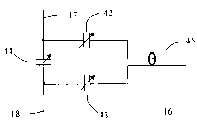
图2为I、Q双通道正交射频线圈电路结构示意图;Fig. 2 is the structural schematic diagram of I, Q dual-channel quadrature radio frequency coil circuit;
图3为射频线圈I通道导体带和电流分布示意图;Fig. 3 is the schematic diagram of conductor strip and current distribution of radio frequency coil I channel;
图4为射频线圈I通道导体带上电容分布示意图;Fig. 4 is a schematic diagram of the capacitance distribution on the I channel conductor of the radio frequency coil;
图5为射频线圈I、Q两通道间隔离电路图;Fig. 5 is the isolation circuit diagram between two channels of radio frequency coil I, Q;
图6为射频线圈各通道输入端口调谐电路图;Fig. 6 is a tuning circuit diagram of each channel input port of the radio frequency coil;
图7为双通道射频线圈立体爆炸工程示意图;Fig. 7 is a schematic diagram of a three-dimensional explosion engineering of a dual-channel radio frequency coil;
图8为双通道射频线圈前向导体带分布平面示意图;Fig. 8 is a schematic diagram of the distribution plane of the forward conductor strips of the dual-channel radio frequency coil;
图9为双通道射频线圈反向导体带分布平面示意图;Fig. 9 is a schematic plan view of the distribution of the reverse conductor strips of the dual-channel radio frequency coil;
图10为双通道射频线圈导体带分布轴截面示意图;Fig. 10 is a schematic cross-sectional view of the distribution axis of the conductor strips of the dual-channel radio frequency coil;
图11为射频线圈射频场B1在Z=0的水平面分布示意图;Fig. 11 is a schematic diagram of the distribution of the radio frequency field B1 of the radio frequency coil at the horizontal plane of Z=0;
图12为射频线圈射频场B1沿Y轴分布曲线图。Fig. 12 is a distribution curve diagram of the radio frequency field B1 of the radio frequency coil along the Y axis.
具体实施方式 Detailed ways
本发明所适用的开放式磁共振成像(MRI)系统磁极和线圈部分结构如图1所示。圆盘状磁极1、2对称分布在成像区域12的上下两侧,磁极一般由钕铁硼磁钢块紧密拼接而成,磁钢的磁场特性大体上确定了静磁场14的大小。磁极1下侧的区域5和磁极2上侧的区域6为静磁场14的调节区,或叫匀场区。通过调节匀场区5、6的匀场部件,能使成像区域12的静磁场14达到所需要的均匀度。匀场区5的下方和匀场区6的上方分别是梯度上盘3和梯度下盘4,每个梯度盘里均含有能产生x、y、z三个方向梯度的梯度线圈,在成像时,它们可以组合出所需要的任意方向的梯度。射频线圈上盘9位于梯度上盘3的下侧,射频线圈下盘10位于梯度下盘4的上侧,射频线圈被激发后在成像区域12产生一均匀水平圆极化射频场15,射频场15围绕着静磁场14旋转,同时激发患者13位于成像区域12的原子核,使其产生磁共振信号。夹在梯度上盘3和射频上盘9中间的薄层是射频屏蔽板7,梯度下盘4和射频下盘10中间是射频屏蔽板8,射频屏蔽板可防止射频场15向梯度盘3、4方向的渗入,也就是说让射频场15能量维持在成像区域12,不至于泄漏到梯度盘后造成能量的损耗。点0为成像区域12的中心,13为待成像的患者示意图,11为成像区域外空间。The structure of the magnetic poles and coils of the open magnetic resonance imaging (MRI) system to which the present invention is applicable is shown in FIG. 1 . The disk-shaped
如图2所示,射频下盘10为I、Q双通道正交线圈,通道I50和通道Q51电路结构基本相同,只是二者的前向电流通路直线导体带互相垂直放置,且基本位于同一平面内。射频上盘9与下盘10呈镜像结构,也是I、Q双通道正交线圈。在射频线圈工作时,上下盘的对应镜像通道电流方向相反,就是说相位差为180度,而同一盘内I、Q两路除空间上互相正交外,相位上也差90度,这样上下盘的四个通道工作时相位分别为0度、90度、180度、270度。射频线圈这样的相位分布才能保证在成像区域12产生沿水平方向的均匀圆极化射频场15。矩形框16表示线圈各通道I/O接口(具体结构见图6),分别接在各通道反向电流通路部分的弧形导体带18、118上。矩形框160表示I、Q两通道间的外加隔离电路(具体结构见图5),接在I通道的弧形导体带18和Q通道的弧形导体带117之间。As shown in Figure 2, the radio frequency
射频盘9、10各自的几何结构,以及它们和成像区域12的中心点0的相对位置关系对成像区域12的射频场15的均匀性以及成像区域外11的场的衰减快慢起着至关重要的作用。具体的说,射频线圈各前向电流通路直线导体带26、27、28、29(见图3)的位置和其中电流I1、I2的大小和比例基本决定了成像区域12的射频场15的大小和均匀性,射频线圈各反向电流通路弧形导体带17、18、19的位置则决定了成像区域外11场的衰减快慢。值得一提的是,各导体带包括直线和弧线段与相应射频屏蔽板的距离大小Z2、Z3(见图10)也对射频场15的分布起着决定性作用。The respective geometric structures of the
射频线圈各路通道的结构都是类似的,下面我们以下盘10的I通道50为例来做详细说明,见图3和图4。前向电流通路24和反向电流通路17、18组成了第一电流回路,前向电流通路25和反向电流通路19组成了第二电流回路。前向电流通路可以只有一根直线导体带由20连到22或者由21连到23,也可以有多根直线导体带,导体带根数越多越容易取得所要射频场15的均匀性,但同时也会增加电路的复杂性,本发明按两根导体带的情况进行说明。这样前向电流通路24就由20、22、26、27等直线导体带组成,前向电流通路25由21、23、28、29等直线导体带组成。前向电流通路24和25中的各导体带以圆盘平分线为对称轴左右对称分布,其中各外侧导体带中的电流I1和内侧导体带中的电流I2也呈对称分布。电流I1、I2的大小比例以及直线导体带26、27、28、29到平分线的距离X1、X2和它们到中心点0的距离Z1(见图10)决定了成像区域12的射频场15的大小和均匀性,具体数值关系可由毕奥-萨法尔定律确定。电流I1、I2的比例又主要取决于直线导体带中电容34、35、36、37的大小,同时它和距离X1、X2也有一定的关系。一般我们最低要求成像区域12的射频场15的均匀性要好于±6dB,稍高的要求是±3dB,也有更高要求达到±1.5dB的。The structures of the channels of the radio frequency coil are similar. Let us take the
第一、第二反向电流通路17、18、19串接着第一、第二前向电流通路24、25,形成完整连续的电流回路,反向电流通路中的电流I3=I1+I2。反向电流通路19连接着前向电流通路25的一端21和前向电流通路24的另外一端22,类似地,反向电流通路17连着前向电流通路24的一端20,反向电流通路18则连着前向电流通路25的另一端23。这样交叉串接的结果就是第一、第二前向电流通路24、25中的电流方向相同,这些同向的电流各自在成像区域12产生方向相同的射频场,总的射频场15为它们的代数和。反向电流通路17、18、19一般为圆弧形状,而且半径相同为rI,即分布在同一个圆周之上。这样做的结果是使射频场15在水平面内的分布趋于各向同性,无论是在成像区域12还是成像区域外11。业内人士知道,反向电流通路也可以用其它的形状,比如椭圆弧、矩形、三角形等等。不过与标准圆弧相比,其它形状反向电流通路可能会造成更大的衰减、灵敏度下降或各向异性。但是业内人士应该明白,无论反向电流通路采取什么形状,均应属于本发明范围内。The first and second reverse
Q通道51前向电流通路、反向电流通路都和I通道50类似,见图2到图4,各通路上串接的电容主要作用是调谐,即让线圈各通道分别谐振在所需频率上。反向电流通路所在圆周的半径rI和rQ的数值决定着射频场15在成像区域外11的衰减快慢。成像区域外11的射频场衰减的越厉害,成像时可能导致折叠的噪声信号就越小。一般要求这个衰减在10dB以上,严格一点的是20dB,最高要求可达到30dB。The forward current path and reverse current path of the
通常rI和rQ大小不同,图2中rQ>rI,I、Q两通道的反向电流通路所在圆周间有一定间距,这样可以提高两通道间的隔离,减小能量损耗。如果两通道半径大小一样,反向电流通路导体带只能在两间隔很小的平行平面内正对放置,这将会出现很大的耦合电容,从而导致隔离很差或者出现额外的噪声和损耗。由于rI和rQ差值的合理存在,我们希望能把隔离保持在15dB到20dB以上。Usually r I and r Q are different in size. In Figure 2, r Q > r I , and there is a certain distance between the circumferences of the reverse current paths of the I and Q channels, which can improve the isolation between the two channels and reduce energy loss. If the radii of the two channels are the same, the reverse current path conductor strips can only be placed directly in two parallel planes with a small distance, which will cause a large coupling capacitance, resulting in poor isolation or additional noise and loss . Due to the reasonable existence of r I and r Q difference, we hope to keep the isolation above 15dB to 20dB.
线圈实际制作过程中由于材料的不均匀、加工精度不够等原因会造成一些不对称因素,导致隔离变差,这样需要在适当的地方加一个隔离电路160来提高I、Q两路间的隔离,见图5。隔离电路160是一简单的由电感41和可调电容40组成的并联电路,选择合适的电感和电容调节范围,可以把隔离调到20dB以上。In the actual production process of the coil, some asymmetric factors will be caused due to uneven material and insufficient processing precision, which will lead to poor isolation. In this way, an
线圈的各通道输入/输出(I/O)端口16均连接于反向电流通路17、18中间的位置,其内部结构如图6所示,由三个可调电容42、43、44组成π型电路,连接着同轴线45的外皮和芯线,这些电容再加上图4中的电容30~37,共同决定着线圈的谐振频率和输入输出阻抗特性。Each channel input/output (I/O)
本发明中,见图7、图8、图9、图10,前向电流通路直线导体带都分布在A平面84附近,反向弧形导体带都分布在B平面114附近,A、B两平面相互平行,有一定距离Z2。B平面114远离成像区域12,也远离患者13,这样比较大的反向电流通路电流I3就远离患者,不至于对患者或附近的医护人员造成过量的电磁辐射。同时,适当调整距离Z2、Z3仍可以改进成像区域12的射频场15的均匀性和它在成像区域外11的衰减特性。In the present invention, see Fig. 7, Fig. 8, Fig. 9, Fig. 10, the straight conductor strips of the forward current path are all distributed near the
因此,我们可以把所有的前向电流通路都做在一个双面电路板67上,所有的反向电流通路都做在另一个双面电路板69上。两电路板67、69分别位于A平面84、B平面114处。其中,电路板67的顶层全部放置I通道50的直线导体带,底层全部放置Q通道51的直线导体带;电路板69的顶层全部放置I通道50的弧形导体带,底层全部放置Q通道的弧形导体带,见图7到图10。不过业内人士应当清楚,用其它方法比如直接用铜带或者其它导体带连接固定在绝缘骨架上形成类似的电路结构也在本发明范围内。电路板一般用介质为FR4的覆铜板制作而成,厚度为1mm到2mm,在分析射频线圈在成像区域的射频场分布时,可以忽略不计,认为所有前向电流通路都位于A平面84内,而所有反向电流通路都位于B平面114内。同一通道中位于不同平面内的前向电流通路和反向电流通路通过连线108~111等连接,连线可采取铆钉、螺钉、导线等多种形式。Therefore, we can make all forward current paths on one double-
归结起来,决定着射频场15在成像区域12的均匀性和成像区域外11的衰减特性的主要因素如下:To sum up, the main factors that determine the uniformity of the
1.反向电流通路平面114和屏蔽板8的距离Z31. The distance Z3 between the reverse
2.前向电流通路平面84和屏蔽板8的距离Z2+Z32. The distance Z2+Z3 between the forward
3.反向电流通路的几何分布情况,rI和rQ的大小3. The geometric distribution of the reverse current path, the size of r I and r Q
4.前向电流通路直线导体带的数量和位置分布X1、X24. Quantity and position distribution of straight conductor strips in the forward current path X1, X2
5.前向电流通路各直线导体带的电流分配比例5. The current distribution ratio of each straight conductor strip in the forward current path
6.成像区域的大小以及中心点O到线圈的距离Z16. The size of the imaging area and the distance Z1 from the center point O to the coil
结合毕奥-萨法尔定律,按给定的要求,可以列出一系列方程,由这些方程即可求出各参数的大小。Combined with the Biot-Safar law, according to the given requirements, a series of equations can be listed, and the size of each parameter can be obtained from these equations.
实施例Example
下面给出一套根据本发明制作出的射频线圈的实际结果。The actual results of a set of radio frequency coils manufactured according to the present invention are given below.
本射频线圈用于开放式磁体中,静磁场B0为铅垂方向,成像区域为直径40cm的球,要求射频场B1在球内的均匀性好于±3dB,在球外距球心35cm的地方衰减大于20dB。射频线圈单盘(包括屏蔽板)的厚度(Z2+Z3)不超过23mm。磁极直径,也就是射频线圈最大直径,为92cm,上下射频盘间距50cm,即Z1为25cm。线圈每个前向电流通路中直线导体为两根,如图2所示,可以算出两直线到平分线的距离X1为4cm,X2为15cm,距离偏差为±1cm。外侧直线导体上电流I1为34A,内侧导体上电流I2为17A,反向电流通路电流I3为51A,电流大小偏差为±2A,。不过实际需要电流的大小由系统所需的射频场B1大小决定,不会固定为上面给出的值。I通道半径rI即其反向电流通路所在圆周半径为38cm,Q通道半径rQ为40cm。前向、反向电流通路距离Z2=13mm,反向电流通路与屏蔽板距离Z3=10mm。 This RF coil is used in an open magnet, the static magnetic field B 0 is the vertical direction, and the imaging area is a ball with a diameter of 40cm. Where the attenuation is greater than 20dB. The thickness (Z2+Z3) of a single disc of the radio frequency coil (including the shielding plate) shall not exceed 23mm. The pole diameter, that is, the maximum diameter of the RF coil, is 92cm, and the distance between the upper and lower RF disks is 50cm, that is, Z1 is 25cm. There are two straight conductors in each forward current path of the coil, as shown in Figure 2, the distance X1 from the two straight lines to the bisector can be calculated as 4cm, X2 is 15cm, and the distance deviation is ±1cm. The current I 1 on the outer straight conductor is 34A, the current I 2 on the inner conductor is 17A, the current I 3 in the reverse current path is 51A, and the current magnitude deviation is ±2A. However, the size of the actual required current is determined by the size of the RF field B 1 required by the system, and will not be fixed to the value given above. The radius r I of the I channel, that is, the radius of the circle where the reverse current path is located, is 38 cm, and the radius r Q of the Q channel is 40 cm. The distance between the forward and reverse current paths is Z2=13mm, and the distance between the reverse current path and the shield plate is Z3=10mm.
通过I/O端口16调谐电容42、43、44可以将输入阻抗调到50欧纯阻状态,此时反射最小,发射效率最高。由于所需频率f不同,电容值变化范围比较大,结合调节电容30~37,一般最后电容42、43在100pF到200pF之间,电容44在200pF到400pF之间比较合适。隔离电路160中,电感41一般为2μH到3μH,电容40为10pF到20pF,这些值除了与频率f有关外,与电路板加工精度、材料均匀性、反向电流通路中电容分布等都有一定关系。By tuning the
图11给出了此线圈在包含中心点O的x-y平面内的射频场B1分布相对大小,取中心点最大值为1,可以看出3dB(对应线性值为0.5)等高线基本上为半径20cm的圆。在3dB线内,磁场分布是比较均匀的,在该线外,磁场衰减很快。Figure 11 shows the relative size of the RF field B1 distribution of this coil in the xy plane containing the center point O, taking the maximum value of the center point as 1, it can be seen that the 3dB (corresponding linear value is 0.5) contour is basically A circle with a radius of 20 cm. Within the 3dB line, the magnetic field distribution is relatively uniform, and outside the line, the magnetic field decays quickly.
图12给出了过中心点O的y轴上的射频场B1分布的dB数,从这幅图可以更明显的看出磁场在中心区的均匀性和成像区域外的快速衰减特性。Figure 12 shows the dB number of the RF field B1 distribution on the y-axis passing through the center point O. From this figure, we can more clearly see the uniformity of the magnetic field in the central area and the rapid attenuation characteristics outside the imaging area.
本例中,每个通道只有四条平行直线导体带,业内人士知道,直线导体带的数目越多,磁场分布可调自由度越大,可达到的均匀性和衰减特性也越高,当然同时线圈设计的复杂度也会提高,因此从工程角度讲,也不是导体带数目越多越好。在一般场合下,四条直线导体带基本上能达到所要的磁场分布特性。此外,各电容、电感等元件的数值,各电流通路导体带数量和位置与具体磁共振系统磁极间空间大小、静磁场B0大小都是相关的。因此上面所给例子并不能说明本发明只适用于这些特定值。In this example, each channel has only four parallel straight conductor strips. People in the industry know that the more the number of straight conductor strips, the greater the degree of freedom in adjusting the magnetic field distribution, and the higher the achievable uniformity and attenuation characteristics. Of course, the coil The complexity of the design will also increase, so from an engineering point of view, the more conductor strips the better. In general situations, four straight conductor strips can basically achieve the desired magnetic field distribution characteristics. In addition, the value of each capacitor, inductor and other components, the number and position of each current path conductor strip are related to the size of the space between the magnetic poles of the specific magnetic resonance system and the size of the static magnetic field B 0 . The examples given above therefore do not imply that the invention is only applicable to these specific values.
Claims (10)
Priority Applications (1)
| Application Number | Priority Date | Filing Date | Title |
|---|---|---|---|
| CNA2006101441810A CN101190127A (en) | 2006-11-29 | 2006-11-29 | A radio frequency coil with flat plate structure |
Applications Claiming Priority (1)
| Application Number | Priority Date | Filing Date | Title |
|---|---|---|---|
| CNA2006101441810A CN101190127A (en) | 2006-11-29 | 2006-11-29 | A radio frequency coil with flat plate structure |
Publications (1)
| Publication Number | Publication Date |
|---|---|
| CN101190127A true CN101190127A (en) | 2008-06-04 |
Family
ID=39485433
Family Applications (1)
| Application Number | Title | Priority Date | Filing Date |
|---|---|---|---|
| CNA2006101441810A Pending CN101190127A (en) | 2006-11-29 | 2006-11-29 | A radio frequency coil with flat plate structure |
Country Status (1)
| Country | Link |
|---|---|
| CN (1) | CN101190127A (en) |
Cited By (6)
| Publication number | Priority date | Publication date | Assignee | Title |
|---|---|---|---|---|
| CN101856229A (en) * | 2010-04-22 | 2010-10-13 | 杜健军 | Radio-frequency coil device in magnetic resonance imaging system |
| CN103126678A (en) * | 2013-02-02 | 2013-06-05 | 浙江大学 | Open type positron emission tomography/magnetic resonance (PET/MR) imaging system for which optical lens serves as optical conduction |
| CN111208459A (en) * | 2020-02-19 | 2020-05-29 | 武汉联影生命科学仪器有限公司 | Magnetic resonance radio frequency coil, magnetic resonance device and magnetic resonance radio frequency coil decoupling method |
| CN113933770A (en) * | 2021-11-25 | 2022-01-14 | 浙江大学 | Component layout method and system based on radio frequency emission surface coil and coil |
| CN114983387A (en) * | 2022-05-31 | 2022-09-02 | 重庆邮电大学 | Low-cost movable ultralow-field nuclear magnetic resonance imaging device |
| CN115079071A (en) * | 2021-03-12 | 2022-09-20 | 上海联影医疗科技股份有限公司 | Magnetic resonance apparatus and control method thereof |
-
2006
- 2006-11-29 CN CNA2006101441810A patent/CN101190127A/en active Pending
Cited By (7)
| Publication number | Priority date | Publication date | Assignee | Title |
|---|---|---|---|---|
| CN101856229A (en) * | 2010-04-22 | 2010-10-13 | 杜健军 | Radio-frequency coil device in magnetic resonance imaging system |
| CN101856229B (en) * | 2010-04-22 | 2013-04-24 | 杜健军 | Radio-frequency coil device in magnetic resonance imaging system |
| CN103126678A (en) * | 2013-02-02 | 2013-06-05 | 浙江大学 | Open type positron emission tomography/magnetic resonance (PET/MR) imaging system for which optical lens serves as optical conduction |
| CN111208459A (en) * | 2020-02-19 | 2020-05-29 | 武汉联影生命科学仪器有限公司 | Magnetic resonance radio frequency coil, magnetic resonance device and magnetic resonance radio frequency coil decoupling method |
| CN115079071A (en) * | 2021-03-12 | 2022-09-20 | 上海联影医疗科技股份有限公司 | Magnetic resonance apparatus and control method thereof |
| CN113933770A (en) * | 2021-11-25 | 2022-01-14 | 浙江大学 | Component layout method and system based on radio frequency emission surface coil and coil |
| CN114983387A (en) * | 2022-05-31 | 2022-09-02 | 重庆邮电大学 | Low-cost movable ultralow-field nuclear magnetic resonance imaging device |
Similar Documents
| Publication | Publication Date | Title |
|---|---|---|
| US20210356539A1 (en) | Radio frequency transmit coil for magnetic resonance imaging system | |
| AU2020248421B2 (en) | Systems and methods for volumetric acquisition in a single-sided MRI system | |
| CN109814054B (en) | RF coil array for MRI systems used in interventional and surgical procedures | |
| US5304932A (en) | Apparatus and method for shielding MRI RF antennae from the effect of surrounding objects | |
| US20060277749A1 (en) | Method and apparatus for magnetic resonance imaging and spectroscopy using microstrip transmission line coils | |
| US20120169335A1 (en) | Multi-element transmit rf chain with local automatic tune and match device | |
| JPH02249531A (en) | Nuclear magnetic resonance method and apparatus | |
| CN104698411B (en) | For the Multi-channel radio-frequency coil of open type magnetic resonance imaging (MRI) system | |
| CN101190127A (en) | A radio frequency coil with flat plate structure | |
| CN204575834U (en) | For the Multi-channel radio-frequency coil of open type magnetic resonance imaging (MRI) system | |
| JPH03106337A (en) | Nuclear magnetic resonance tomograph | |
| KR20210121097A (en) | Elastic Resonant Trap Circuit | |
| Alt et al. | Coaxial waveguide MRI | |
| Woo et al. | Extended monopole antenna array with individual shield (EMAS) coil: An improved monopole antenna design for brain imaging at 7 tesla MRI | |
| US20150241529A1 (en) | Loop Coil with Integrated Balun for MR Applications | |
| JP2019180851A (en) | Array coil and magnetic resonance imaging apparatus | |
| EP1269211B1 (en) | Magnetic resonance imaging apparatus with means to screen rf fields | |
| US10473736B2 (en) | Subject-loaded helical-antenna radio-frequency coil for magnetic resonance imaging | |
| CN200994776Y (en) | Radio-frequency coil with planar structure | |
| US20100109667A1 (en) | Transverse electromagnetic radio-frequency coil | |
| CN107526049A (en) | A kind of multinuclear metabolic imaging double frequency head coil for super high field | |
| CN107064839A (en) | A kind of magnetic resonance imaging radiofrequency coil that left/right hand microstrip line is combined based on point shape | |
| CN207164230U (en) | A kind of multinuclear metabolic imaging double frequency head coil for super high field | |
| US10816620B2 (en) | Method for controlling the distribution of the RF magnetic field in a magnetic resonance imaging system | |
| KR102214831B1 (en) | Radio frequency surface coil and Magnetic resonance imaging system comprising the same |
Legal Events
| Date | Code | Title | Description |
|---|---|---|---|
| C06 | Publication | ||
| PB01 | Publication | ||
| C10 | Entry into substantive examination | ||
| SE01 | Entry into force of request for substantive examination | ||
| C02 | Deemed withdrawal of patent application after publication (patent law 2001) | ||
| WD01 | Invention patent application deemed withdrawn after publication |