US5175396A - Low-electric stress insulating wall for high voltage coils having roebeled strands - Google Patents
Low-electric stress insulating wall for high voltage coils having roebeled strands Download PDFInfo
- Publication number
- US5175396A US5175396A US07/627,277 US62727790A US5175396A US 5175396 A US5175396 A US 5175396A US 62727790 A US62727790 A US 62727790A US 5175396 A US5175396 A US 5175396A
- Authority
- US
- United States
- Prior art keywords
- layer
- wall structure
- insulating
- semiconductive
- high voltage
- Prior art date
- Legal status (The legal status is an assumption and is not a legal conclusion. Google has not performed a legal analysis and makes no representation as to the accuracy of the status listed.)
- Expired - Lifetime
Links
- 239000000463 material Substances 0.000 claims abstract description 38
- 239000004593 Epoxy Substances 0.000 claims abstract description 28
- 239000011800 void material Substances 0.000 claims abstract description 17
- 238000004804 winding Methods 0.000 claims abstract description 8
- OKTJSMMVPCPJKN-UHFFFAOYSA-N Carbon Chemical compound [C] OKTJSMMVPCPJKN-UHFFFAOYSA-N 0.000 claims abstract description 5
- 229910052799 carbon Inorganic materials 0.000 claims abstract description 5
- 230000001788 irregular Effects 0.000 claims description 9
- 230000015572 biosynthetic process Effects 0.000 claims description 4
- 239000000945 filler Substances 0.000 claims description 3
- 230000001939 inductive effect Effects 0.000 claims description 2
- 239000004020 conductor Substances 0.000 claims 4
- 238000000465 moulding Methods 0.000 abstract 1
- 239000011810 insulating material Substances 0.000 description 8
- 239000003990 capacitor Substances 0.000 description 7
- 238000004519 manufacturing process Methods 0.000 description 6
- 239000010445 mica Substances 0.000 description 6
- 229910052618 mica group Inorganic materials 0.000 description 6
- 239000003822 epoxy resin Substances 0.000 description 4
- 238000000034 method Methods 0.000 description 4
- 229920000647 polyepoxide Polymers 0.000 description 4
- 238000009423 ventilation Methods 0.000 description 4
- RYGMFSIKBFXOCR-UHFFFAOYSA-N Copper Chemical compound [Cu] RYGMFSIKBFXOCR-UHFFFAOYSA-N 0.000 description 2
- 229920004934 Dacron® Polymers 0.000 description 2
- 229910052802 copper Inorganic materials 0.000 description 2
- 239000010949 copper Substances 0.000 description 2
- 238000010586 diagram Methods 0.000 description 2
- 238000009413 insulation Methods 0.000 description 2
- 239000003973 paint Substances 0.000 description 2
- 239000002966 varnish Substances 0.000 description 2
- 238000003491 array Methods 0.000 description 1
- 238000010420 art technique Methods 0.000 description 1
- 230000006835 compression Effects 0.000 description 1
- 238000007906 compression Methods 0.000 description 1
- 230000005520 electrodynamics Effects 0.000 description 1
- 239000004744 fabric Substances 0.000 description 1
- 239000007789 gas Substances 0.000 description 1
- 239000011521 glass Substances 0.000 description 1
- 229910052739 hydrogen Inorganic materials 0.000 description 1
- 239000001257 hydrogen Substances 0.000 description 1
- 125000004435 hydrogen atom Chemical class [H]* 0.000 description 1
- 239000012212 insulator Substances 0.000 description 1
- 239000012811 non-conductive material Substances 0.000 description 1
- 239000004065 semiconductor Substances 0.000 description 1
- 229920001187 thermosetting polymer Polymers 0.000 description 1
Images


Classifications
-
- H—ELECTRICITY
- H02—GENERATION; CONVERSION OR DISTRIBUTION OF ELECTRIC POWER
- H02K—DYNAMO-ELECTRIC MACHINES
- H02K3/00—Details of windings
- H02K3/32—Windings characterised by the shape, form or construction of the insulation
- H02K3/40—Windings characterised by the shape, form or construction of the insulation for high voltage, e.g. affording protection against corona discharges
-
- Y—GENERAL TAGGING OF NEW TECHNOLOGICAL DEVELOPMENTS; GENERAL TAGGING OF CROSS-SECTIONAL TECHNOLOGIES SPANNING OVER SEVERAL SECTIONS OF THE IPC; TECHNICAL SUBJECTS COVERED BY FORMER USPC CROSS-REFERENCE ART COLLECTIONS [XRACs] AND DIGESTS
- Y10—TECHNICAL SUBJECTS COVERED BY FORMER USPC
- Y10S—TECHNICAL SUBJECTS COVERED BY FORMER USPC CROSS-REFERENCE ART COLLECTIONS [XRACs] AND DIGESTS
- Y10S174/00—Electricity: conductors and insulators
- Y10S174/13—High voltage cable, e.g. above 10kv, corona prevention
- Y10S174/26—High voltage cable, e.g. above 10kv, corona prevention having a plural-layer insulation system
- Y10S174/27—High voltage cable, e.g. above 10kv, corona prevention having a plural-layer insulation system including a semiconductive layer
Definitions
- This invention generally relates to insulators for covering a high voltage component having an irregular surface, and is specifically concerned with an insulating wall structure for covering a high voltage coil having Roebeled strands on its outer surface that tend to create unwanted void spaces in the insulating material forming the wall.
- Wall structures for insulating the high voltage coils used in power-producing alternators are known in the prior art. Such wall structures are made after the coil strands have been consolidated into a coil stack by applying strips of a material treated with an insulative, thermosetting epoxy over the top and bottom surfaces of the coil stack. The coil and the strips of epoxy-treated material are then placed within a heatable press assembly which simultaneously heats and compresses the strips of epoxy-treated material which causes them first to liquefy and to fill the space between the irregular surfaces on the coil exterior, and then to harden. A mica tape ground wall is formed around the consolidated coil and vacuum impregnated with an epoxy resin. The ground wall is completed by applying a conductive varnish over the impregnated mica tape. The resulting insulated coil is then assembled within a power-generating alternator.
- Roebel bars In order to minimize the losses which would occur in these coils as a result of unwanted eddy currents, the windings of these coils are intertwined in a braid-like form known as a Roebel bar.
- the outer surfaces of such Roebel bars are highly discontinuous, as the relatively thick and flat strands do not smoothly align with one another on the same plane on the surface of the coil, but instead disjointedly overlap.
- the surface discontinuities presented by the twisted and overlapping Roebeled strands tends to create a number of air gaps in the outer surface of the coil (known as "void spaces" in the art) which provide potential sites for unwanted arcing if each such gap is not completely filled with insulating material.
- the invention is an improved wall structure for insulating the exterior surface of a high voltage component that comprises an inner layer formed from an insulating material disposed over the surface of the component, an outer ground wall for grounding the wall structure, and a layer of semiconductive material for reducing the electric stress across the inner insulating layer.
- the semiconductive layer is preferably disposed between the outer surface of the inner insulating layer, and the inner surface of the ground wall.
- the improved wall structure may further comprise a connection means between the high voltage component and the layer of semiconductive material to further lower the electric stress over the inner insulating layer.
- the insulating wall structure of the invention is particularly adapted for use on a high voltage coil having Roebeled strands on its outer surface.
- the inner insulating layer is preferably formed from a hardenable, nonconductive material such as epoxy which is effective in filling void spaces on the surface of the component which arise as a result of the irregular geometry of the Roebeled strands.
- the semiconductive layer is likewise preferably formed from a hardenable material such a carbon-filled epoxy so that both the insulating layer and the semiconductive layer can be integrally molded into a single strong wall structure.
- the semiconducting properties of the semiconductive layer effectively reduces the electric stress across the inner insulating layer, and in particular across any small pockets of air which might be present in the insulating layer as a result of the failure of the hardenable epoxy to completely fill all of the numerous void spaces present on the coil.
- the invention is particularly applicable to coils having Roebeled strands which are operated at between 20 and 24 kilovolts. Under such operating conditions, the resistance of the semiconductive material forming this semiconductive layer may be between about 5,000 and 50,000 ohms per square, and is preferably on the order of between 8,000 and 20,000 ohms per square.
- the invention further contemplates a method for forming an insulating wall structure around an electrical component such as a high voltage coil having Roebeled strands on its exterior that applies only a small amount of electric stress to its insulating layer.
- a hardenable, insulating material such as epoxy is liquefied and then applied around the outer surface of the component under pressure to fill void spaces created by the presence of the Roebeled strands.
- a hardenable, semiconductive material such as carbon-filled epoxy is applied around the outer surface of the insulating layer so that both the inner insulating layer and the semiconductive layer harden together to form a single, integral wall structure.
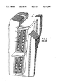
- FIG. 1 is a perspective view of a coil section having Roebeled windings on its top and bottom ends that is insulated by means of a prior art insulating wall structure;
- FIG. 2 illustrates how the coil section shown in FIG. 1 fits within the slots of the stator assembly of an alternator
- FIG. 3 is a perspective view of a coil section having Roebeled strands on its top and bottom ends that are insulated by the wall structure of the invention
- FIG. 4 is a partial cross-sectional view of the coil illustrated in FIG. 3 along the line 4--4, illustrating both the semiconductive layer and the connective interface between this layer and the top coil strand of the coil section;
- FIG. 5 is a cross-sectional view of a coil section insulated by means of an alternate embodiment of the invention, wherein the semiconductive layer does not entirely circumscribe the array of coil strands, but only covers the top and bottom ends of the strand array;
- FIGS. 6A and 6B are schematic diagrams illustrating how the semiconductive layer of the insulating wall of the invention increases the capacitance between the outer surface of the array of high voltage strands and the outer surface of the inner insulating layer, and thereby lowers the electric stress applied to the inner insulating layer, and
- FIG. 7 is a graph comparing how the electric stress applied across an insulating wall structure increases with voltage for both the prior art coil section illustrated in FIG. 1 (which is shown in dotted lines), and the improved insulating wall structure of the invention (shown in solid lines).
- the purpose of the invention is to provide an insulating wall structure for a high voltage component, such as a high voltage coil section 1 of the type used is power-generating alternators.
- a high voltage component such as a high voltage coil section 1 of the type used is power-generating alternators.
- Such coil sections 1 include an array 3 of consolidated copper strands 4, each of which is generally rectangular in cross section. In the array 3, these strands 4 are arranged in rows and columns.
- Such strand arrays 3 include one or more ventilation passageways 5 which conducts a heat-dissipating gas, such as hydrogen, during the operation of the coil section 1 in an alternator or other electro-dynamic machine.
- a heat-dissipating gas such as hydrogen
- this ventilation passageway 5 is located between two stacked columns of strands 4 as shown. Such passageway typically houses a ventilation tube (not shown). Such ventilation passageways may, in the alternative, be incorporated in some of the strands 4 themselves.
- the array 3 of coil strands 4 is normally completely covered by an insulating wall structure 7, shown in cross section near the rear portion of the perspective view of the coil section 1 illustrated in FIG. 1.
- the insulating wall structure of the invention may be advantageously used in conjunction with any one of a number of high voltage components, it is particularly adapted for use with a high voltage coil section 1 of the type used in power-generating alternators.
- Such coil sections 1 are, in operation, mounted within the slots 9 of the stator assembly 11 of such an alternator (see FIG. 2).
- the strands on the top and bottom ends 13,14 are "braided" to form Roebeled strands 15a,b and 16a,b respectively, (see FIG. 1).
- the individual strands 4 of the coil 1 are insulated from each other by paper-thin insulative sheets 20, which may be formed from thin glass cloth that has been impregnated with an insulating, epoxy resin.
- These layers 20 may be thin because even though the voltage conducted through the coil 1 may be as high as 24 kv, the voltage between individual adjacent strands 4 is only about 5 volts, being caused only by the impedance of the individual coil strand 4 as the current makes its way through the coil 1.
- the difference in potential between the strands 4 of the coil 1 and ground is on the order of 20 kv. Accordingly, much heavier insulation in the form of the previously mentioned insulative wall structure 7 surrounds the entire strand array 3.
- This wall structure 7 generally comprises an inner insulating layer 26 formed from layers of epoxy impregnated Dacron® felt which are applied over the top and bottom ends 13,14 of the strand array 3, and a ground wall 27 formed from an insulating layer 26 of micatape impregnated with epoxy and disposed over the layer 26 of felt and completely around the strand array 3 as shown, and an outer conductive layer 29 formed from conductive paint.
- FIG. 3 illustrates the insulating wall structure 30 of the invention.
- the wall structure 30 of the invention includes an inner, insulating layer 31 formed from a nonconductive thermosettable epoxy material that is generally capable of filling the irregular spaces 18a,b,c formed by the Roebeled strands 15a,b and 16a,b.
- layer 31 is formed from a combination of mica paper and B stage epoxy.
- this structure 30 includes a semiconductive layer 32 between the inner insulating layer 31, and the ground wall 27.
- the semiconductive layer 32 is formed from a paste of carbon-filled epoxy material which may be fused into and hence structurally integrated with the nonconductive epoxy material forming the inner insulating layer 31 when the wall structure 30 is manufactured by the simultaneous application of heat and pressure thereto.
- the resulting integrality of the layers 31 and 32 not only provides the same kind of structural integrity associated with the prior art wall structure 7; it further helps to prevent the formation of any additional void spaces between the two layers 31 and 32.
- the exterior surface of the semiconductive layer is covered by means of a ground wall 27 which is identical in structure to the ground wall 27 discussed with respect to the prior art.
- the resistivity of the semi-conductive layer 32 is chosen to be low enough so that the electric stress across the insulating layer 31 is substantially lessened, but yet high enough so that no unwanted short circuiting is likely to occur between individual strands in the array 3. Accordingly, when the voltage applied through the array 3 of coil strands is on the order of 20 to 25 kilovolts, the resistance of the semiconductive layer 32 is chosen to be somewhere between 5,000 and 50,000 ohms per square, and more preferably between about 8,000 and 20,000 ohms per square. Also in the preferred embodiment, the semiconductive layer is between 0.3 and 0.6 in thickness.
- the semiconductive layer 32 of the insulative wall structure 30 of the invention may be electrically connected to one of the strands 15a,b or 16a,b on either the top or bottom end 13,14 of the strand array 3 by means of a connection interface 35.
- this connection interface 35 is merely an opening in the insulative filler material forming the inner insulating layer 31 through which the semiconducting epoxy resin that forms the semi-conducting layer 32 may penetrate when the epoxy materials forming both the layers 31 and 32 are simultaneously subjected to both heat and pressure.
- connection interface 35 When such a connection interface 35 is incorporated within the insulative wall structure 30 of the invention, the total electrical potential experienced within the insulating layer 31 is considerably lowered, as will be discussed in more detail with respect to FIG. 7.
- the resistance of the material forming the semiconductive layer 32 is preferably higher than the resistance of this layer when no such connection interface 35 is provided. Specifically, this resistance should be about 10,000 ohms without the interface 35, but raised up to a level of about 40,000 ohms per square when such an interface 35 is provided.
- FIG. 5 illustrates an alternate embodiment of the insulative wall structure 30 of the invention, wherein the semiconductive layer is broken up into two layers 38a,b which cover only the top and bottoms ends 13,14 of the coil array 3. Because the insulating layer 31 completely isolates the Roebeled strands 15a,b on the top end 13 of the array 3 from the Roebeled strands 16a,b on the bottom end 14 of the array 3, two connection interfaces 40a,b may be provided which separately connect each of the semiconductive layers 38a,b to the coil array 3.
- This particular embodiment of the invention advantageously provides somewhat better insulation around the high voltage coil section 1 as a whole, since the sides of the strand array 3 are completely covered in insulating filler material formed from the inner insulating layer 31 and the inner layer 28 of the ground wall 27.
- the electric stress in the sides will not be reduced to the level that they are with respect to the first embodiment of the invention illustrated in FIG. 3.
- this is only a small disadvantage, as most all of the void regions which might occur in the insulating material will occur at the top and bottom ends 13,14 of the strand array 3, as these are the areas of the array 3 characterized by discontinuous surfaces.
- FIGS. 6A and 6B are schematic diagrams illustrating the theory of operation of the invention. Specifically, FIG. 6A represents how the ground wall 27 and inner insulating layer 26 of the prior art wall structure 7 essentially forms two series-connected capacitors wherein the electrodes of the upper capacitor are formed by the conductive paint layer 29 and the interface between the mica and epoxy layer 28 of the ground wall and the semiconductor layer 32, and the electrodes of the lower capacitor are formed by the interface between the aforementioned layers 28 and 32, and the surface of the strand array 3.
- the electric stress experienced by the insulating material forming the layer 25 is directly proportional to the reactance of the insulative wall structure 7, which in turn is inversely proportional to the capacitance of the capacitor schematically illustrated in FIG. 6A.
- FIG. 6B illustrates how this capacitance is indeed increased by the presence of the semiconductive layer 32 in the insulative wall structure 30 of the invention.
- the conductive ability of the semiconductive layer 32 effectively reduces the distance between the capacitor plates formed by the surface of the strand array 3, and the interface between the layer 28 and 32.
- the area of the plates 3 and 29 is increased, as the stress is no longer located at only the top and bottom ends 13,14 of the strand array 3, but now encompasses all sides of the strand array 3 due to the fact that the semiconductive layer completely surrounds the array 3.
- FIG. 7 is a graph that compares the relative ability of the prior art insulative wall 7 to the ability of the insulative wall 30 of the invention in reducing electric stress through the wall.
- the abscissa of this graph represents a quantity known as "tangent delta", which is proportional to the amount of current losses which occur in a coil section 1 as a result of unwanted arcing within the insulative wall which covers the coil strands, while the ordinate of the graph represents electric potential in kilovolts.
- Dashed graph A represents how tangent delta increases over voltage with a prior art insulative wall structure 7, while solid line graph B illustrates how tangent delta increases with voltage for either of the two embodiments of the invention illustrated in FIGS. 4 and 5.
- Solid line graph C illustrates how tangent delta increases with applied voltage for an embodiment of the invention which includes the semiconductive layer 31, but which does not include any connection interfaces 35,40a,b between an individual strand 4 of the strand array 3, and the semiconductive layer 31.
Landscapes
- Engineering & Computer Science (AREA)
- Power Engineering (AREA)
- Insulation, Fastening Of Motor, Generator Windings (AREA)
- Insulating Of Coils (AREA)
- Insulated Conductors (AREA)
Abstract
Description
Claims (17)
Priority Applications (6)
| Application Number | Priority Date | Filing Date | Title |
|---|---|---|---|
| US07/627,277 US5175396A (en) | 1990-12-14 | 1990-12-14 | Low-electric stress insulating wall for high voltage coils having roebeled strands |
| JP3351452A JPH077878A (en) | 1990-12-14 | 1991-12-12 | Wall structure insulating outer face of high-voltage parts and its formation |
| ES91311639T ES2075373T3 (en) | 1990-12-14 | 1991-12-13 | PROCEDURE FOR THE FORMATION OF AN INSULATION WALL OF REDUCED ELECTRIC EFFORTS FOR HIGH VOLTAGE COILS MADE OF ROEBEL TYPE WIRE. |
| EP91311639A EP0490705B1 (en) | 1990-12-14 | 1991-12-13 | Method for forming a low-electric stress insulating wall for high voltage coils having roebeled strands |
| DE69110632T DE69110632T2 (en) | 1990-12-14 | 1991-12-13 | Process for the production of insulation of low dielectric stress for high voltage coils with Roebel rods. |
| CA002057602A CA2057602A1 (en) | 1990-12-14 | 1991-12-13 | Low-electric stress insulating wall for high voltage coils having roebeled strands |
Applications Claiming Priority (1)
| Application Number | Priority Date | Filing Date | Title |
|---|---|---|---|
| US07/627,277 US5175396A (en) | 1990-12-14 | 1990-12-14 | Low-electric stress insulating wall for high voltage coils having roebeled strands |
Publications (1)
| Publication Number | Publication Date |
|---|---|
| US5175396A true US5175396A (en) | 1992-12-29 |
Family
ID=24513996
Family Applications (1)
| Application Number | Title | Priority Date | Filing Date |
|---|---|---|---|
| US07/627,277 Expired - Lifetime US5175396A (en) | 1990-12-14 | 1990-12-14 | Low-electric stress insulating wall for high voltage coils having roebeled strands |
Country Status (6)
| Country | Link |
|---|---|
| US (1) | US5175396A (en) |
| EP (1) | EP0490705B1 (en) |
| JP (1) | JPH077878A (en) |
| CA (1) | CA2057602A1 (en) |
| DE (1) | DE69110632T2 (en) |
| ES (1) | ES2075373T3 (en) |
Cited By (51)
| Publication number | Priority date | Publication date | Assignee | Title |
|---|---|---|---|---|
| US5962945A (en) * | 1997-04-17 | 1999-10-05 | Alcatel | Multiple parallel conductor |
| US5979087A (en) * | 1998-01-16 | 1999-11-09 | Reliance Electric Industrial Company | Electric motor having electrostatic shield arrangement |
| US6011338A (en) * | 1998-07-10 | 2000-01-04 | Reliance Electric Industrial Company | Electric motor having auxiliary winding arrangement for electrostatic shielding |
| WO2000033443A1 (en) * | 1998-12-02 | 2000-06-08 | Siemens Westinghouse Power Corporation | Method to reduce partial discharge in high voltage stator coil's roebel filler |
| US6202285B1 (en) * | 1998-01-16 | 2001-03-20 | Reliance Electric Technologies, Llc | Electric motor having electrostatic shield arrangement |
| EP1154542A1 (en) * | 2000-05-12 | 2001-11-14 | ALSTOM Power N.V. | Coil insulating method |
| EP1193830A2 (en) | 2000-09-06 | 2002-04-03 | Siemens Westinghouse Power Corporation | High voltage stator coil having low loss insulator and electrode covering and method therefor |
| US20020084100A1 (en) * | 1998-12-18 | 2002-07-04 | Electrolock, Inc. | Conductive filler |
| US6420812B1 (en) | 2000-09-07 | 2002-07-16 | Siemens Westinghouse Power Corporation | High voltage generator stator coils and methods of forming same |
| US20020125787A1 (en) * | 2000-08-04 | 2002-09-12 | Howard Raymond T. | Stator coil assembly for superconducting rotating machines |
| US20030001441A1 (en) * | 2001-06-29 | 2003-01-02 | Bae Systems Controls Inc. | Stator construction for high performance rotating machines |
| US20030197309A1 (en) * | 2002-01-31 | 2003-10-23 | Karim Younsi | Method of making a dynamoelectric machine conductor bar and method of making a conductor bar dynamoelectric machine, the bar and the machine |
| US6646363B2 (en) | 1997-02-03 | 2003-11-11 | Abb Ab | Rotating electric machine with coil supports |
| US20030218273A1 (en) * | 2000-09-01 | 2003-11-27 | Ryozo Takeuchi | Method of manufacture of resin block |
| US20040046474A1 (en) * | 2000-08-04 | 2004-03-11 | American Superconductor Corporation, A Delaware Corporation | Stator coil assembly for superconducting rotating machines |
| US6724118B2 (en) * | 2001-06-13 | 2004-04-20 | Siemens Westinghouse Power Corporation | Electrical isolation layer system strand assembly and method of forming for electrical generator |
| US20040100154A1 (en) * | 2002-11-26 | 2004-05-27 | Rahman Khwaja M. | Concentrated winding electric motor having optimized winding cooling and slot fill |
| US6825585B1 (en) | 1997-02-03 | 2004-11-30 | Abb Ab | End plate |
| US6836047B1 (en) | 1999-05-27 | 2004-12-28 | Abb Ab | Electric machine with low eddy current losses |
| US6867674B1 (en) | 1997-11-28 | 2005-03-15 | Asea Brown Boveri Ab | Transformer |
| US6873080B1 (en) | 1997-09-30 | 2005-03-29 | Abb Ab | Synchronous compensator plant |
| US20050077075A1 (en) * | 2003-10-09 | 2005-04-14 | Yu Wang | Flexible stator bars |
| US6970063B1 (en) | 1997-02-03 | 2005-11-29 | Abb Ab | Power transformer/inductor |
| US6972505B1 (en) | 1996-05-29 | 2005-12-06 | Abb | Rotating electrical machine having high-voltage stator winding and elongated support devices supporting the winding and method for manufacturing the same |
| US6995646B1 (en) | 1997-02-03 | 2006-02-07 | Abb Ab | Transformer with voltage regulating means |
| US7019429B1 (en) | 1997-11-27 | 2006-03-28 | Asea Brown Boveri Ab | Method of applying a tube member in a stator slot in a rotating electrical machine |
| US7045704B2 (en) | 2000-04-28 | 2006-05-16 | Abb Ab | Stationary induction machine and a cable therefor |
| US7046492B2 (en) | 1997-02-03 | 2006-05-16 | Abb Ab | Power transformer/inductor |
| US20060214530A1 (en) * | 2005-03-22 | 2006-09-28 | Siemens Westinghouse Power Corporation | Electrical-discharge-inhibiting conformable layer for use in inner-cooler coils |
| US7141908B2 (en) | 2000-03-01 | 2006-11-28 | Abb Ab | Rotating electrical machine |
| US20070296299A1 (en) * | 2006-06-27 | 2007-12-27 | Ronghai Qu | Electrical machine with improved windings |
| US20080029291A1 (en) * | 2006-08-04 | 2008-02-07 | Lisa Marie Sternberg | Liquid-cooled stator bars and a method for manufacturing the same |
| US20080143465A1 (en) * | 2006-12-15 | 2008-06-19 | General Electric Company | Insulation system and method for a transformer |
| US20080227648A1 (en) * | 2007-03-16 | 2008-09-18 | Siemens Power Generation, Inc. | Winding for Use in High Temperature Superconducting Generator |
| WO2008116113A1 (en) * | 2007-03-20 | 2008-09-25 | Electrolock, Inc. | Roebel winding with conductive felt |
| US20080284262A1 (en) * | 2004-06-15 | 2008-11-20 | Siemens Power Generation, Inc. | Stator coil with improved heat dissipation |
| US20100051317A1 (en) * | 2008-08-29 | 2010-03-04 | Pratt & Whitney Canada Corp. | Crack controlled resin insulated electrical coil |
| US20100188601A1 (en) * | 2009-01-29 | 2010-07-29 | Tomohisa Onishi | Light emitting diode backlight unit and liquid crystal display device having the same |
| US20110062816A1 (en) * | 2009-09-16 | 2011-03-17 | Emery Franklin T | Tape Structure with Conductive Outer Side and Electrically Insulating Inner Side |
| US20110068643A1 (en) * | 2009-09-18 | 2011-03-24 | Emery Franklin T | Voltage Grading Structure in a High-Voltage Stator Coil of an Electromotive Machine |
| US20110181145A1 (en) * | 2010-01-22 | 2011-07-28 | Thomas Baumann | Conductive bar for electric machines |
| US20120161568A1 (en) * | 2009-09-11 | 2012-06-28 | Kawasaki Jukogyo Kabushiki Kaisha | Superconducting rotating electrical machine and stator for use with superconducting rotating electrical machine |
| US20120286523A1 (en) * | 2011-05-10 | 2012-11-15 | The Boeing Company | Reconfigurable stators |
| US20130199819A1 (en) * | 2010-05-12 | 2013-08-08 | Essex Europe | Method for production of an electrical winding, and electrical conductor |
| US20150162796A1 (en) * | 2012-03-27 | 2015-06-11 | Mitsubishi Electric Corporation | Stator and rotating electrical machine equipped with the same |
| US9059616B1 (en) | 2014-08-20 | 2015-06-16 | Dantam K. Rao | Insulation system for a stator bar with low partial discharge |
| US20170047803A1 (en) * | 2014-04-15 | 2017-02-16 | Siemens Aktiengesellschaft | Stator of an electric machine and production thereof |
| US20210036568A1 (en) * | 2019-07-30 | 2021-02-04 | Florian Schulz | Coil arrangement for an electrical machine |
| US20220021249A1 (en) * | 2019-03-29 | 2022-01-20 | Denso Corporation | Rotating electric machine |
| US11804748B2 (en) | 2021-06-03 | 2023-10-31 | The Timken Company | Corona protection insulation system |
| US12212203B2 (en) * | 2020-01-08 | 2025-01-28 | Hitachi Astemo, Ltd. | Stator of rotating electrical machine, insulating member for rotating electrical machine, and rotating electrical machine |
Families Citing this family (27)
| Publication number | Priority date | Publication date | Assignee | Title |
|---|---|---|---|---|
| DE69725181D1 (en) | 1996-05-29 | 2003-10-30 | Abb Ab Vaesteraas | LADDER FOR HIGH VOLTAGE WINDINGS AND ROTATING ELECTRICAL MACHINE WITH SUCH A LADDER |
| KR20000016122A (en) | 1996-05-29 | 2000-03-25 | 에이비비 에이비 | Transformer/reactor |
| AU718707B2 (en) | 1996-05-29 | 2000-04-20 | Abb Ab | Insulated conductor for high-voltage windings and a method of manufacturing the same |
| SE510192C2 (en) | 1996-05-29 | 1999-04-26 | Asea Brown Boveri | Procedure and switching arrangements to reduce problems with three-tier currents that may occur in alternator and motor operation of AC machines connected to three-phase distribution or transmission networks |
| UA45452C2 (en) | 1996-05-29 | 2002-04-15 | Абб Аб | HIGH VOLTAGE AC ELECTRIC MACHINE (OPTIONS) AND DISTRIBUTION OR MAIN NETWORK |
| SE9602079D0 (en) | 1996-05-29 | 1996-05-29 | Asea Brown Boveri | Rotating electric machines with magnetic circuit for high voltage and a method for manufacturing the same |
| SE515843C2 (en) | 1996-11-04 | 2001-10-15 | Abb Ab | Axial cooling of rotor |
| SE512917C2 (en) | 1996-11-04 | 2000-06-05 | Abb Ab | Method, apparatus and cable guide for winding an electric machine |
| SE509072C2 (en) | 1996-11-04 | 1998-11-30 | Asea Brown Boveri | Anode, anodizing process, anodized wire and use of such wire in an electrical device |
| SE510422C2 (en) | 1996-11-04 | 1999-05-25 | Asea Brown Boveri | Magnetic sheet metal core for electric machines |
| SE508544C2 (en) | 1997-02-03 | 1998-10-12 | Asea Brown Boveri | Method and apparatus for mounting a stator winding consisting of a cable. |
| SE9704427D0 (en) | 1997-02-03 | 1997-11-28 | Asea Brown Boveri | Fastening device for electric rotary machines |
| SE508543C2 (en) | 1997-02-03 | 1998-10-12 | Asea Brown Boveri | Coiling |
| SE9704431D0 (en) | 1997-02-03 | 1997-11-28 | Asea Brown Boveri | Power control of synchronous machine |
| SE9704421D0 (en) | 1997-02-03 | 1997-11-28 | Asea Brown Boveri | Series compensation of electric alternator |
| SE510590C2 (en) * | 1997-09-30 | 1999-06-07 | Asea Brown Boveri | Electrical insulation for a conductor arranged for generating a magnetic field in a plurality of turns, a method for insulating the conductor and using the insulation |
| GB2331867A (en) | 1997-11-28 | 1999-06-02 | Asea Brown Boveri | Power cable termination |
| BR9815420A (en) | 1997-11-28 | 2001-07-17 | Abb Ab | Method and device for controlling the magnetic flux with an auxiliary winding on a rotating high voltage alternating current machine |
| GB2331858A (en) | 1997-11-28 | 1999-06-02 | Asea Brown Boveri | A wind power plant |
| US6801421B1 (en) | 1998-09-29 | 2004-10-05 | Abb Ab | Switchable flux control for high power static electromagnetic devices |
| GB9907527D0 (en) * | 1999-04-01 | 1999-05-26 | Alstom Uk Ltd | Improvements in electrical machines |
| US6885273B2 (en) | 2000-03-30 | 2005-04-26 | Abb Ab | Induction devices with distributed air gaps |
| US8288911B2 (en) * | 2006-12-15 | 2012-10-16 | General Electric Company | Non-linear dielectrics used as electrical insulation for rotating electrical machinery |
| WO2009152858A1 (en) * | 2008-06-19 | 2009-12-23 | Siemens Transformers Austria Gmbh & Co Kg | Continuously transposed conductor for a winding for an electric machine |
| EP2405558A1 (en) * | 2010-07-05 | 2012-01-11 | Alstom Technology Ltd | Stator Bar |
| NL2005439C2 (en) * | 2010-10-01 | 2012-04-03 | Draad Nijmegen B V | A multiple parallel conductor for an electrical machine. |
| EP2860858A1 (en) * | 2014-04-10 | 2015-04-15 | Alstom Technology Ltd | Manufacturing method of a conductor bar |
Citations (20)
| Publication number | Priority date | Publication date | Assignee | Title |
|---|---|---|---|---|
| US2705292A (en) * | 1953-05-07 | 1955-03-29 | Siemens Ag | Slot conductor for dynamoelectric machines |
| GB765420A (en) * | 1954-03-22 | 1957-01-09 | Comp Generale Electricite | Process for the manufacture of high tension electric cables |
| DE1053090B (en) * | 1955-12-30 | 1959-03-19 | Siemens Ag | Process for the production of conductor bars composed of partial conductors for electrical high-voltage machines |
| US3327050A (en) * | 1964-07-29 | 1967-06-20 | Ici Ltd | Cables with 4-methyl pentene-1 primary insulation |
| US3329764A (en) * | 1965-05-17 | 1967-07-04 | Jr John H Tanges | Conductive plastic cable shield |
| US3576387A (en) * | 1970-03-19 | 1971-04-27 | Chomerics Inc | Heat shrinkable electromagnetic shield for electrical conductors |
| FR2293816A1 (en) * | 1974-12-04 | 1976-07-02 | Bbc Brown Boveri & Cie | BAR WINDINGS WITH ELEMENTARY STRANDED CONDUCTORS FOR ELECTRIC MACHINES, AND METHOD FOR ITS MANUFACTURING |
| DE2851388A1 (en) * | 1977-11-29 | 1979-05-31 | Ferdy Mayer | HIGH FREQUENCY EMISSION CABLE OR CABLE |
| EP0036911A1 (en) * | 1980-03-28 | 1981-10-07 | BBC Aktiengesellschaft Brown, Boveri & Cie. | Bar winding with transposed partial conductors for an electric machine with nominal voltages greater than 3,3 kV and process for manufacturing the bar winding |
| US4314737A (en) * | 1979-06-14 | 1982-02-09 | Virginia Patent Development Corp. | Cable assembly having shielded conductor and method of making same |
| FR2489054A1 (en) * | 1980-08-23 | 1982-02-26 | Bbc Brown Boveri & Cie | CONDUCTOR SHAFT FOR AN ELECTRIC MACHINE AND METHOD FOR MANUFACTURING THE SAME |
| US4510077A (en) * | 1983-11-03 | 1985-04-09 | General Electric Company | Semiconductive glass fibers and method |
| US4602180A (en) * | 1985-01-07 | 1986-07-22 | General Electric Company | Insulated armature coil for dynamoelectric machine |
| US4724600A (en) * | 1985-04-16 | 1988-02-16 | Westinghouse Electric Corp. | Method of making a high voltage dynamoelectric machine with selectively increased coil turn-to-turn insulation strength |
| JPH01152939A (en) * | 1987-12-08 | 1989-06-15 | Toshiba Corp | Winding of rotary electric machine |
| US4853565A (en) * | 1984-08-23 | 1989-08-01 | General Electric Company | Semi-conducting layer for insulated electrical conductors |
| US4988949A (en) * | 1989-05-15 | 1991-01-29 | Westinghouse Electric Corp. | Apparatus for detecting excessive chafing of a cable arrangement against an electrically grounded structure |
| US5036165A (en) * | 1984-08-23 | 1991-07-30 | General Electric Co. | Semi-conducting layer for insulated electrical conductors |
| US5067046A (en) * | 1984-08-23 | 1991-11-19 | General Electric Company | Electric charge bleed-off structure using pyrolyzed glass fiber |
| US5066881A (en) * | 1984-08-23 | 1991-11-19 | General Electric Company | Semi-conducting layer for insulated electrical conductors |
-
1990
- 1990-12-14 US US07/627,277 patent/US5175396A/en not_active Expired - Lifetime
-
1991
- 1991-12-12 JP JP3351452A patent/JPH077878A/en active Pending
- 1991-12-13 DE DE69110632T patent/DE69110632T2/en not_active Expired - Lifetime
- 1991-12-13 CA CA002057602A patent/CA2057602A1/en not_active Abandoned
- 1991-12-13 ES ES91311639T patent/ES2075373T3/en not_active Expired - Lifetime
- 1991-12-13 EP EP91311639A patent/EP0490705B1/en not_active Expired - Lifetime
Patent Citations (22)
| Publication number | Priority date | Publication date | Assignee | Title |
|---|---|---|---|---|
| US2705292A (en) * | 1953-05-07 | 1955-03-29 | Siemens Ag | Slot conductor for dynamoelectric machines |
| GB765420A (en) * | 1954-03-22 | 1957-01-09 | Comp Generale Electricite | Process for the manufacture of high tension electric cables |
| DE1053090B (en) * | 1955-12-30 | 1959-03-19 | Siemens Ag | Process for the production of conductor bars composed of partial conductors for electrical high-voltage machines |
| US3327050A (en) * | 1964-07-29 | 1967-06-20 | Ici Ltd | Cables with 4-methyl pentene-1 primary insulation |
| US3329764A (en) * | 1965-05-17 | 1967-07-04 | Jr John H Tanges | Conductive plastic cable shield |
| US3576387A (en) * | 1970-03-19 | 1971-04-27 | Chomerics Inc | Heat shrinkable electromagnetic shield for electrical conductors |
| US4308476A (en) * | 1974-12-04 | 1981-12-29 | Bbc Brown Boveri & Co. Ltd. | Bar windings for electrical machines |
| FR2293816A1 (en) * | 1974-12-04 | 1976-07-02 | Bbc Brown Boveri & Cie | BAR WINDINGS WITH ELEMENTARY STRANDED CONDUCTORS FOR ELECTRIC MACHINES, AND METHOD FOR ITS MANUFACTURING |
| DE2851388A1 (en) * | 1977-11-29 | 1979-05-31 | Ferdy Mayer | HIGH FREQUENCY EMISSION CABLE OR CABLE |
| US4314737A (en) * | 1979-06-14 | 1982-02-09 | Virginia Patent Development Corp. | Cable assembly having shielded conductor and method of making same |
| EP0036911A1 (en) * | 1980-03-28 | 1981-10-07 | BBC Aktiengesellschaft Brown, Boveri & Cie. | Bar winding with transposed partial conductors for an electric machine with nominal voltages greater than 3,3 kV and process for manufacturing the bar winding |
| FR2489054A1 (en) * | 1980-08-23 | 1982-02-26 | Bbc Brown Boveri & Cie | CONDUCTOR SHAFT FOR AN ELECTRIC MACHINE AND METHOD FOR MANUFACTURING THE SAME |
| US4403163A (en) * | 1980-08-23 | 1983-09-06 | Brown, Boveri & Cie Ag | Conductor bar for electric machines and method of manufacture thereof |
| US4510077A (en) * | 1983-11-03 | 1985-04-09 | General Electric Company | Semiconductive glass fibers and method |
| US4853565A (en) * | 1984-08-23 | 1989-08-01 | General Electric Company | Semi-conducting layer for insulated electrical conductors |
| US5036165A (en) * | 1984-08-23 | 1991-07-30 | General Electric Co. | Semi-conducting layer for insulated electrical conductors |
| US5067046A (en) * | 1984-08-23 | 1991-11-19 | General Electric Company | Electric charge bleed-off structure using pyrolyzed glass fiber |
| US5066881A (en) * | 1984-08-23 | 1991-11-19 | General Electric Company | Semi-conducting layer for insulated electrical conductors |
| US4602180A (en) * | 1985-01-07 | 1986-07-22 | General Electric Company | Insulated armature coil for dynamoelectric machine |
| US4724600A (en) * | 1985-04-16 | 1988-02-16 | Westinghouse Electric Corp. | Method of making a high voltage dynamoelectric machine with selectively increased coil turn-to-turn insulation strength |
| JPH01152939A (en) * | 1987-12-08 | 1989-06-15 | Toshiba Corp | Winding of rotary electric machine |
| US4988949A (en) * | 1989-05-15 | 1991-01-29 | Westinghouse Electric Corp. | Apparatus for detecting excessive chafing of a cable arrangement against an electrically grounded structure |
Non-Patent Citations (2)
| Title |
|---|
| "Prepegs for Pre-Consolidation of Coils for High Voltage Machines"; Jan. 1987; Isovolta (4 pages). |
| Prepegs for Pre Consolidation of Coils for High Voltage Machines ; Jan. 1987; Isovolta (4 pages). * |
Cited By (81)
| Publication number | Priority date | Publication date | Assignee | Title |
|---|---|---|---|---|
| US6972505B1 (en) | 1996-05-29 | 2005-12-06 | Abb | Rotating electrical machine having high-voltage stator winding and elongated support devices supporting the winding and method for manufacturing the same |
| US6646363B2 (en) | 1997-02-03 | 2003-11-11 | Abb Ab | Rotating electric machine with coil supports |
| US6970063B1 (en) | 1997-02-03 | 2005-11-29 | Abb Ab | Power transformer/inductor |
| US6825585B1 (en) | 1997-02-03 | 2004-11-30 | Abb Ab | End plate |
| US6995646B1 (en) | 1997-02-03 | 2006-02-07 | Abb Ab | Transformer with voltage regulating means |
| US7046492B2 (en) | 1997-02-03 | 2006-05-16 | Abb Ab | Power transformer/inductor |
| US5962945A (en) * | 1997-04-17 | 1999-10-05 | Alcatel | Multiple parallel conductor |
| US6873080B1 (en) | 1997-09-30 | 2005-03-29 | Abb Ab | Synchronous compensator plant |
| US7019429B1 (en) | 1997-11-27 | 2006-03-28 | Asea Brown Boveri Ab | Method of applying a tube member in a stator slot in a rotating electrical machine |
| US6867674B1 (en) | 1997-11-28 | 2005-03-15 | Asea Brown Boveri Ab | Transformer |
| US5979087A (en) * | 1998-01-16 | 1999-11-09 | Reliance Electric Industrial Company | Electric motor having electrostatic shield arrangement |
| US6720692B2 (en) | 1998-01-16 | 2004-04-13 | Reliance Electric Technologies, Llc | Electric motor having electrostatic shield arrangement |
| US6202285B1 (en) * | 1998-01-16 | 2001-03-20 | Reliance Electric Technologies, Llc | Electric motor having electrostatic shield arrangement |
| US6011338A (en) * | 1998-07-10 | 2000-01-04 | Reliance Electric Industrial Company | Electric motor having auxiliary winding arrangement for electrostatic shielding |
| US6228494B1 (en) | 1998-12-02 | 2001-05-08 | Siemens Westinghouse Power Corporation | Method to reduce partial discharge in high voltage stator coil's roebel filler |
| WO2000033443A1 (en) * | 1998-12-02 | 2000-06-08 | Siemens Westinghouse Power Corporation | Method to reduce partial discharge in high voltage stator coil's roebel filler |
| US20020084100A1 (en) * | 1998-12-18 | 2002-07-04 | Electrolock, Inc. | Conductive filler |
| US6559384B1 (en) | 1998-12-18 | 2003-05-06 | Electrolock, Inc. | Conductive filler |
| US6827805B2 (en) | 1998-12-18 | 2004-12-07 | Electrolock, Inc. | Method of making a conductive filler |
| US6836047B1 (en) | 1999-05-27 | 2004-12-28 | Abb Ab | Electric machine with low eddy current losses |
| US7141908B2 (en) | 2000-03-01 | 2006-11-28 | Abb Ab | Rotating electrical machine |
| US7045704B2 (en) | 2000-04-28 | 2006-05-16 | Abb Ab | Stationary induction machine and a cable therefor |
| EP1154542A1 (en) * | 2000-05-12 | 2001-11-14 | ALSTOM Power N.V. | Coil insulating method |
| US6888286B2 (en) * | 2000-08-04 | 2005-05-03 | American Superconductor Corporation | Stator coil assembly for superconducting rotating machines |
| US20040046474A1 (en) * | 2000-08-04 | 2004-03-11 | American Superconductor Corporation, A Delaware Corporation | Stator coil assembly for superconducting rotating machines |
| US20020125787A1 (en) * | 2000-08-04 | 2002-09-12 | Howard Raymond T. | Stator coil assembly for superconducting rotating machines |
| US6911759B2 (en) * | 2000-08-04 | 2005-06-28 | American Superconductor Corporation | Stator coil assembly for superconducting rotating machines |
| US6730255B2 (en) * | 2000-09-01 | 2004-05-04 | Hitachi, Ltd. | Method of manufacture of resin block |
| US20030218273A1 (en) * | 2000-09-01 | 2003-11-27 | Ryozo Takeuchi | Method of manufacture of resin block |
| EP1193830A2 (en) | 2000-09-06 | 2002-04-03 | Siemens Westinghouse Power Corporation | High voltage stator coil having low loss insulator and electrode covering and method therefor |
| US6498415B1 (en) | 2000-09-06 | 2002-12-24 | Siemens Westinghouse Power Corporation | High voltage stator coil having low loss insulator and electrode covering and method therefor |
| US6420812B1 (en) | 2000-09-07 | 2002-07-16 | Siemens Westinghouse Power Corporation | High voltage generator stator coils and methods of forming same |
| US6724118B2 (en) * | 2001-06-13 | 2004-04-20 | Siemens Westinghouse Power Corporation | Electrical isolation layer system strand assembly and method of forming for electrical generator |
| US20030001441A1 (en) * | 2001-06-29 | 2003-01-02 | Bae Systems Controls Inc. | Stator construction for high performance rotating machines |
| US6787948B2 (en) * | 2001-06-29 | 2004-09-07 | Bae Systems Controls Inc. | Stator construction for high performance rotating machines |
| US20030197309A1 (en) * | 2002-01-31 | 2003-10-23 | Karim Younsi | Method of making a dynamoelectric machine conductor bar and method of making a conductor bar dynamoelectric machine, the bar and the machine |
| US6768240B2 (en) * | 2002-01-31 | 2004-07-27 | General Electric Company | Method of making a dynamoelectric machine conductor bar and method of making a conductor bar dynamoelectric machine, the bar and the machine |
| US20040100154A1 (en) * | 2002-11-26 | 2004-05-27 | Rahman Khwaja M. | Concentrated winding electric motor having optimized winding cooling and slot fill |
| US20060053620A1 (en) * | 2003-10-09 | 2006-03-16 | Yu Wang | Flexible stator bars |
| US20050077075A1 (en) * | 2003-10-09 | 2005-04-14 | Yu Wang | Flexible stator bars |
| US20080284262A1 (en) * | 2004-06-15 | 2008-11-20 | Siemens Power Generation, Inc. | Stator coil with improved heat dissipation |
| US8030818B2 (en) * | 2004-06-15 | 2011-10-04 | Siemens Energy, Inc. | Stator coil with improved heat dissipation |
| US20060214530A1 (en) * | 2005-03-22 | 2006-09-28 | Siemens Westinghouse Power Corporation | Electrical-discharge-inhibiting conformable layer for use in inner-cooler coils |
| US7391141B2 (en) * | 2005-03-22 | 2008-06-24 | Siemens Power Generation, Inc. | Electrical-discharge-inhibiting conformable layer for use in inner-cooler coils |
| US7705243B2 (en) | 2005-03-22 | 2010-04-27 | Siemens Energy, Inc. | Electrical-discharge-inhibiting conformable layer for use in inner-cooled coils |
| US20080236865A1 (en) * | 2005-03-22 | 2008-10-02 | Siemens Power Generation, Inc. | Electrical-discharge-inhibiting conformable layer for use in inner-cooled coils |
| CN101098099B (en) * | 2006-06-27 | 2011-11-16 | 通用电气公司 | Electrical machine with improved winding |
| US20070296299A1 (en) * | 2006-06-27 | 2007-12-27 | Ronghai Qu | Electrical machine with improved windings |
| US7521835B2 (en) * | 2006-06-27 | 2009-04-21 | General Electric Company | Permanent magnet machine with windings having strand transposition |
| US7634852B2 (en) | 2006-08-04 | 2009-12-22 | General Electric Company | Method for manufacturing liquid-cooled stator bars |
| US20080029291A1 (en) * | 2006-08-04 | 2008-02-07 | Lisa Marie Sternberg | Liquid-cooled stator bars and a method for manufacturing the same |
| US20080143465A1 (en) * | 2006-12-15 | 2008-06-19 | General Electric Company | Insulation system and method for a transformer |
| US8630688B2 (en) | 2007-03-16 | 2014-01-14 | Siemens Energy, Inc. | Winding for use in high temperature superconducting generator |
| US20080227648A1 (en) * | 2007-03-16 | 2008-09-18 | Siemens Power Generation, Inc. | Winding for Use in High Temperature Superconducting Generator |
| US20080230253A1 (en) * | 2007-03-20 | 2008-09-25 | Electrolock, Inc. | Roebel winding with conductive felt |
| WO2008116113A1 (en) * | 2007-03-20 | 2008-09-25 | Electrolock, Inc. | Roebel winding with conductive felt |
| US7893357B2 (en) | 2007-03-20 | 2011-02-22 | Electrolock, Inc. | Roebel winding with conductive felt |
| US20100051317A1 (en) * | 2008-08-29 | 2010-03-04 | Pratt & Whitney Canada Corp. | Crack controlled resin insulated electrical coil |
| US7982133B2 (en) | 2008-08-29 | 2011-07-19 | Pratt & Whitney Canada Corp. | Crack controlled resin insulated electrical coil |
| US20100188601A1 (en) * | 2009-01-29 | 2010-07-29 | Tomohisa Onishi | Light emitting diode backlight unit and liquid crystal display device having the same |
| US8643240B2 (en) * | 2009-09-11 | 2014-02-04 | Kawasaki Jukogyo Kabushiki Kaisha | Superconducting rotating electrical machine and stator for use with superconducting rotating electrical machine |
| US20120161568A1 (en) * | 2009-09-11 | 2012-06-28 | Kawasaki Jukogyo Kabushiki Kaisha | Superconducting rotating electrical machine and stator for use with superconducting rotating electrical machine |
| US8395296B2 (en) | 2009-09-16 | 2013-03-12 | Siemens Energy, Inc. | Tape structure with conductive outer side and electrically insulating inner side |
| US20110062816A1 (en) * | 2009-09-16 | 2011-03-17 | Emery Franklin T | Tape Structure with Conductive Outer Side and Electrically Insulating Inner Side |
| US8278795B2 (en) * | 2009-09-18 | 2012-10-02 | Siemens Energy, Inc. | Voltage grading structure in a high-voltage stator coil of an electromotive machine |
| US20110068643A1 (en) * | 2009-09-18 | 2011-03-24 | Emery Franklin T | Voltage Grading Structure in a High-Voltage Stator Coil of an Electromotive Machine |
| US20110181145A1 (en) * | 2010-01-22 | 2011-07-28 | Thomas Baumann | Conductive bar for electric machines |
| US20130199819A1 (en) * | 2010-05-12 | 2013-08-08 | Essex Europe | Method for production of an electrical winding, and electrical conductor |
| US9111668B2 (en) * | 2010-05-12 | 2015-08-18 | Essex Europe | Method for production of an electrical winding, and electrical conductor |
| US20120286523A1 (en) * | 2011-05-10 | 2012-11-15 | The Boeing Company | Reconfigurable stators |
| US8803384B2 (en) * | 2011-05-10 | 2014-08-12 | The Boeing Company | Stators with reconfigurable coil paths |
| US20150162796A1 (en) * | 2012-03-27 | 2015-06-11 | Mitsubishi Electric Corporation | Stator and rotating electrical machine equipped with the same |
| US10298083B2 (en) * | 2012-03-27 | 2019-05-21 | Mitsubishi Electric Corporation | Rotating electrical machine equipped with a stator having a bus bar wrapped with insulation sheet/layers |
| US20170047803A1 (en) * | 2014-04-15 | 2017-02-16 | Siemens Aktiengesellschaft | Stator of an electric machine and production thereof |
| US10651699B2 (en) * | 2014-04-15 | 2020-05-12 | Siemens Aktiengesellschaft | Stator of an electric machine and production thereof |
| US9059616B1 (en) | 2014-08-20 | 2015-06-16 | Dantam K. Rao | Insulation system for a stator bar with low partial discharge |
| US20220021249A1 (en) * | 2019-03-29 | 2022-01-20 | Denso Corporation | Rotating electric machine |
| US20210036568A1 (en) * | 2019-07-30 | 2021-02-04 | Florian Schulz | Coil arrangement for an electrical machine |
| US11909286B2 (en) * | 2019-07-30 | 2024-02-20 | Rolls-Royce Deutschland Ltd & Co Kg | Coil arrangement for an electrical machine |
| US12212203B2 (en) * | 2020-01-08 | 2025-01-28 | Hitachi Astemo, Ltd. | Stator of rotating electrical machine, insulating member for rotating electrical machine, and rotating electrical machine |
| US11804748B2 (en) | 2021-06-03 | 2023-10-31 | The Timken Company | Corona protection insulation system |
Also Published As
| Publication number | Publication date |
|---|---|
| JPH077878A (en) | 1995-01-10 |
| DE69110632D1 (en) | 1995-07-27 |
| DE69110632T2 (en) | 1996-03-21 |
| EP0490705B1 (en) | 1995-06-21 |
| CA2057602A1 (en) | 1992-06-15 |
| EP0490705A1 (en) | 1992-06-17 |
| ES2075373T3 (en) | 1995-10-01 |
Similar Documents
| Publication | Publication Date | Title |
|---|---|---|
| US5175396A (en) | Low-electric stress insulating wall for high voltage coils having roebeled strands | |
| US4001616A (en) | Grounding of outer winding insulation to cores in dynamoelectric machines | |
| RU2406174C2 (en) | High voltage wall bushing | |
| US6130495A (en) | Supporting element for an electric winding, turbogenerator and method of producing a corona shield | |
| US6768240B2 (en) | Method of making a dynamoelectric machine conductor bar and method of making a conductor bar dynamoelectric machine, the bar and the machine | |
| JP2004508800A (en) | Stepped electric field insulation system for dynamoelectric machine | |
| EP1933444A2 (en) | Non-linear dielectrics used as electrical insulation | |
| US4847450A (en) | Stress graded electrical bushing and method of making same | |
| US6420812B1 (en) | High voltage generator stator coils and methods of forming same | |
| US3823334A (en) | Electrical apparatus with high voltage electrical conductor insulated by material including high dielectric constant inserts | |
| EP1933332A1 (en) | Insulation system and method for a transformer | |
| KR100643499B1 (en) | How to Reduce Partial Discharge in Loevel Fillings of High Voltage Stator Coils | |
| AU9290898A (en) | Insulation for a conductor | |
| US3646251A (en) | Electrical bushing having stress-grading layer disposed within solid insulation including a ground layer term inated at each end with a layer of material having a voltage-dependent resistivity | |
| JP2000510316A (en) | Conductor winding structure of large electric machine | |
| US2939976A (en) | Corona suppression in high voltage coils | |
| CA2861321C (en) | High voltage stator coil with reduced power tip-up | |
| US11605994B2 (en) | Winding insulation system | |
| JPS58157350A (en) | Insulated coil for rotary electric machine | |
| US11804748B2 (en) | Corona protection insulation system | |
| JPH0638424A (en) | Stator coil of high-tension rotating electric machine | |
| JPH11346450A (en) | Stator coil of high-pressure rotating machine | |
| CN117809947A (en) | Transformer coil | |
| JPS59165936A (en) | Stator coil of rotary electric machine | |
| RU2000117269A (en) | TRANSFORMER-REACTOR AND METHOD FOR ITS MANUFACTURE |
Legal Events
| Date | Code | Title | Description |
|---|---|---|---|
| AS | Assignment |
Owner name: WESTINGHOUSE ELECTRIC CORPORATION, WESTINGHOUSE BU Free format text: ASSIGNMENT OF ASSIGNORS INTEREST.;ASSIGNORS:EMERY, FRANKLIN T.;SIMMONDS, LEONARD B.;FORT, EMIL M.;REEL/FRAME:005545/0469;SIGNING DATES FROM 19901203 TO 19901204 |
|
| STCF | Information on status: patent grant |
Free format text: PATENTED CASE |
|
| CC | Certificate of correction | ||
| FEPP | Fee payment procedure |
Free format text: PAYOR NUMBER ASSIGNED (ORIGINAL EVENT CODE: ASPN); ENTITY STATUS OF PATENT OWNER: LARGE ENTITY |
|
| FPAY | Fee payment |
Year of fee payment: 4 |
|
| AS | Assignment |
Owner name: SIEMENS WESTINGHOUSE POWER CORPORATION, FLORIDA Free format text: ASSIGNMENT NUNC PRO TUNC EFFECTIVE AUGUST 19, 1998;ASSIGNOR:CBS CORPORATION, FORMERLY KNOWN AS WESTINGHOUSE ELECTRIC CORPORATION;REEL/FRAME:009605/0650 Effective date: 19980929 |
|
| FEPP | Fee payment procedure |
Free format text: PAYER NUMBER DE-ASSIGNED (ORIGINAL EVENT CODE: RMPN); ENTITY STATUS OF PATENT OWNER: LARGE ENTITY Free format text: PAYOR NUMBER ASSIGNED (ORIGINAL EVENT CODE: ASPN); ENTITY STATUS OF PATENT OWNER: LARGE ENTITY |
|
| FPAY | Fee payment |
Year of fee payment: 8 |
|
| FPAY | Fee payment |
Year of fee payment: 12 |
|
| AS | Assignment |
Owner name: SIEMENS POWER GENERATION, INC., FLORIDA Free format text: CHANGE OF NAME;ASSIGNOR:SIEMENS WESTINGHOUSE POWER CORPORATION;REEL/FRAME:016996/0491 Effective date: 20050801 |
|
| AS | Assignment |
Owner name: SIEMENS ENERGY, INC., FLORIDA Free format text: CHANGE OF NAME;ASSIGNOR:SIEMENS POWER GENERATION, INC.;REEL/FRAME:022482/0740 Effective date: 20081001 Owner name: SIEMENS ENERGY, INC.,FLORIDA Free format text: CHANGE OF NAME;ASSIGNOR:SIEMENS POWER GENERATION, INC.;REEL/FRAME:022482/0740 Effective date: 20081001 |