US5042854A - Latch assembly - Google Patents
Latch assembly Download PDFInfo
- Publication number
- US5042854A US5042854A US07/452,969 US45296989A US5042854A US 5042854 A US5042854 A US 5042854A US 45296989 A US45296989 A US 45296989A US 5042854 A US5042854 A US 5042854A
- Authority
- US
- United States
- Prior art keywords
- latch
- plug member
- guiding lever
- assembly
- latch assembly
- Prior art date
- Legal status (The legal status is an assumption and is not a legal conclusion. Google has not performed a legal analysis and makes no representation as to the accuracy of the status listed.)
- Expired - Lifetime
Links
Images


Classifications
-
- E—FIXED CONSTRUCTIONS
- E05—LOCKS; KEYS; WINDOW OR DOOR FITTINGS; SAFES
- E05C—BOLTS OR FASTENING DEVICES FOR WINGS, SPECIALLY FOR DOORS OR WINDOWS
- E05C1/00—Fastening devices with bolts moving rectilinearly
- E05C1/08—Fastening devices with bolts moving rectilinearly with latching action
- E05C1/10—Fastening devices with bolts moving rectilinearly with latching action with operating handle or equivalent member rigid with the latch
-
- Y—GENERAL TAGGING OF NEW TECHNOLOGICAL DEVELOPMENTS; GENERAL TAGGING OF CROSS-SECTIONAL TECHNOLOGIES SPANNING OVER SEVERAL SECTIONS OF THE IPC; TECHNICAL SUBJECTS COVERED BY FORMER USPC CROSS-REFERENCE ART COLLECTIONS [XRACs] AND DIGESTS
- Y10—TECHNICAL SUBJECTS COVERED BY FORMER USPC
- Y10T—TECHNICAL SUBJECTS COVERED BY FORMER US CLASSIFICATION
- Y10T292/00—Closure fasteners
- Y10T292/08—Bolts
- Y10T292/096—Sliding
- Y10T292/0969—Spring projected
- Y10T292/097—Operating means
- Y10T292/0997—Rigid
Definitions
- the present invention relates to a latch assembly, including a latch and a latch-guiding lever, which can reciprocatingly move between an extended, latching position and a retracted, unlatching position and, in particular, such a latch assembly which prevents slippage between the latch and the latch-guiding lever.
- Known latch or latch locking structures usually use a spring to position the latch at the latched position and a manual latch-guiding lever to push the latch to the retracted position.
- the latch and latch-guiding lever are usually assembled using conventional threaded joint or press-on packing assembly methods.
- such conventional methods of assembly often cause damage, particularly to the threads, or looseness of the component parts of the latch assembly, due to use over an extended period of time or infrequent pushes or excessive external forces.
- the latch-guiding lever may even loosen and slip off from the latch, causing the latch or latch-locking assembly to lose its assigned function and thereby cause extreme user difficulties.
- an object of the present invention to provide a latch assembly that can actually prevent the latch-guiding lever from getting loose or slipping off, whose assembly is convenient and simple, and whose latch-guiding lever may be easily and conventionally pushed.
- Another object of the present invention is to provide a latch assembly of the above type in a simple design and economic construction for easy assembly, disassembly and replacement, thereby lowering both manufacturing and maintenance costs.
- a latch assembly in accordance with the foregoing and other objects, comprises an outside housing element and a latch that can reciprocatingly move between an extended, latching position and a retracted, unlatching position.
- a transverse hole is provided in the latch.
- a manually controlled latch-guiding lever is partly extended into the hole in the latch.
- a recessed slot is provided on the part of the latch that it inserted into the hole in the latch. Under the elastic force of a spring, a portion of a plug member is urged into the recessed hole to prevent the latch-guiding lever from loosening and slipping off the latch.
- a pull element is provided to pull the plug member and separate it from the latch-guiding lever, thereby enabling disassembly of the latch assembly.
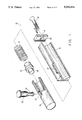
- FIG. 1 is an exploded view of various component elements of a first embodiment of a latch assembly in accordance with the present invention
- FIG. 2 is an elevational, sectional view of the assembled component elements of the embodiment shown in FIG. 1;
- FIG. 3 is an elevational, sectional view of a second embodiment of a latch assembly in accordance with the present invention.
- FIG. 4 is an elevational, sectional view of a third embodiment of a latch assembly in accordance with the present invention.
- FIG. 5 is a view, partly in section, of a file clamp incorporating a latch assembly in accordance with the third embodiment of the invention.
- FIG. 6 is an elevational, sectional view of a fourth embodiment of a latch assembly in accordance with the present invention.
- a first embodiment of a latch assembly 10 in accordance with the present invention includes an outside housing element 12 which can be made in any type and form to match different uses, for instance, the latch assembly 10 may be made into a door latch, window latch, suit case latch, key chain latch, file clamp and so on.
- the latch assembly 10 includes a latch 14 which is enclosed in the outside housing element 12 with a part 16 of the latch 14 protruding outside of the outside housing element 12 to achieve the latching action for an article (not shown).
- the latch 14 can reciprocatingly move from the latching position or the completely extended position, as shown in FIG. 2, to the retracted position inside the outside housing element 12.
- One feature of the present invention lies in the provision of a radial hole 22, which may be a through-hole, in a suitable position of the latch 14 to allow a latch-guiding lever 20 to extend therein.
- a recessed slot 24 is provided on the part of the latch-guiding lever 20 that extends into the hole 22.
- a plug member 26 is positioned between the latch-guiding lever 20 and a compression spring so that the spring 18 causes a head 28 of the plug member 26 to extend into the hole 22 and to bear against the recessed slot 24 of the latch-guiding lever 20. Accordingly, the plug member 26 prevents the latch-guiding lever 20 from being pulled out of the hole 22, thereby preventing any loosening and slipping-off between the latch 14 and the latch-guiding lever 20.
- the latch assembly 10 also includes an axial pull element 30 having one end fixed to the plug member 26. If necessary to disassemble the latch assembly 10, the pull element 30 may be pulled manually to remove the head 28 of the plug member 26 from the recessed slot 24 of the latch-guiding lever 20, thereby enabling the latch-guiding lever 20 to be freely pulled out of the hole 22 to separate the latch 14 and disassemble the latch assembly 10.
- a slot 32 is provided on the outside housing element 12 to allow movement of the latch-guiding lever 20.
- the slot 32 also limits the positions of the dead points for the latch-guiding lever 20 and other members during their reciprocating travels.
- a hole 34 is provided on an end plate 36 attached at the end of the outside housing element 12 to allow the axial push element 30 to reciprocate.
- the latch assembly 40 comprises an outside housing element 42 of any suitable type to match the use of the latch assembly, a latch 44 that can reciprocatingly move between an extended, latching position and a retracted, unlatched position, a latch-guiding lever 50 that can extend into a radial hole 52 in the latch 44, a plug member 56 that can be placed into a recessed slot 54 on the latch-guiding lever, and a compression spring 48 that generates a push force for the latch 44 and plug member 56.
- the latch assembly 40 includes a pull element 58 which is radially positioned with respect to the plug member 56.
- One end of the pull element 58 is fixed to the plug member 56 to facilitate applying a force to the plug member 56 to axially separate it from the recessed slot 54 on the latch-guiding lever 50.
- Two slot holes 46 and 47 in an equal length are respectively provided on the outside housing element 42 to respectively allow the radial latch-guiding lever 50 and pull element 58 to have limited reciprocating movements.
- FIG. 4 there is shown an embodiment of the invention useful as a file clamp or any other similar article.
- This embodiment comprises an outside housing element 62 on which a radial hole 64 is provided to allow a tooth-shaped rod 66 to be inserted therein; a plug member 68 having a head 70; a spring 72; and an axial pull element 76. Under the elastic force of the spring 72, the head 70 of the plug member 68 may be laid into any tooth valley 74 of the tooth-shaped rod 66. The pull element 76 is used to manually pull the head 70 of the plug member out of the tooth valley 74 of the tooth-shaped rod.
- FIG. 5 there is shown the embodiment of FIG. 4 used as a file clamp for a classic adjustable file assembly 80.
- the file assembly 80 has an outside housing element 82 which is appropriately lengthened to accommodate a file clamp at each end thereof.
- Each file clamp includes a hole 84 into which a tooth-shaped rod 86 is inserted.
- Each rod 86 is fixed to respective opposite ends of a holding plate 98.
- Each file clamp further includes a plug member 88; a spring 92; and a radial pull element 96.
- the heads 90 of the two plug members are inserted into appropriate tooth valleys 94 of the tooth-shaped rods 86 to firmly clamp a document 90.
- the specific tooth valleys 94 into which the heads 90 are inserted depends upon the thickness of the document to be clamped.
- the latch assembly 100 comprises an outside housing element 102 of any suitable type to match the use of the latch assembly, a latch 104 that can reciprocatingly move between an extended latching position and a retracted, unlatched position; a latch-guiding lever 110 that can extend into a radial hole 112 in the latch 104; a plug member 116 that can be placed into a recessed slot 114 in the latch-guiding lever, and a spring 108 that generates a push force to the latch 104 and the plug member 116.
- the latch assembly 100 differs from the latch assembly 10 of the first embodiment and the latch assembly 40 of the second exemplary embodiment in that the latch assembly 100 is not provided with any means to separately pull the plug member 116. However, like the other embodiments, the latch assembly 106 also prevents the latch-guiding latch 110 from loosening or slipping-off from the latch 104, but its structure is simplified to lower its manufacture costs.
Landscapes
- Engineering & Computer Science (AREA)
- Mechanical Engineering (AREA)
- Details Of Connecting Devices For Male And Female Coupling (AREA)
Abstract
A latch assembly includes a latch that can reciprocatingly move between an extended, latching position and a retracted, unlatching position. A latch-guiding lever having a recessed slot extends into a transverse hole in the latch. A plug member under the elastic force of a spring is urged into the recessed slot, thereby preventing any loosening or slipping-off of the latch-guiding lever from the latch. A pull element may be provided to separate the plug member from the latch-guiding lever to thereby enable disassembly of the latch assembly.
Description
The present invention relates to a latch assembly, including a latch and a latch-guiding lever, which can reciprocatingly move between an extended, latching position and a retracted, unlatching position and, in particular, such a latch assembly which prevents slippage between the latch and the latch-guiding lever.
Known latch or latch locking structures usually use a spring to position the latch at the latched position and a manual latch-guiding lever to push the latch to the retracted position. The latch and latch-guiding lever are usually assembled using conventional threaded joint or press-on packing assembly methods. However, such conventional methods of assembly often cause damage, particularly to the threads, or looseness of the component parts of the latch assembly, due to use over an extended period of time or infrequent pushes or excessive external forces. Indeed, the latch-guiding lever may even loosen and slip off from the latch, causing the latch or latch-locking assembly to lose its assigned function and thereby cause extreme user difficulties.
With respect to latch-guiding levers and latches that are assembled by means of thread connections, troubles may be generated due to the extent to which the threads are tightened. If they are overly tightened, this will increase the diameter of the head of the latch-guiding lever causing excessive friction between the lever and its guide slot wall, thereby making it more difficult for users to push the latch-guiding lever; if they are not tightened sufficiently, this will make the latch-guiding lever protrude outside too much, thereby causing the latch-guiding lever to easily loosen and even slip off from the latch.
To overcome the problem of the latch-guiding lever loosening and slipping off, inverse installed screws and clamp spring packing means have been used to replace the conventional screw assembly. Although this solved the loosening and slipping-off phenomenon of the latch-guiding lever, it added difficulties during assembly, caused inconvenience to users and added higher costs.
From the foregoing, it should be evident that a latch assembly that is easy to assemble and can also avoid the loosening and slipping off of the latch-guiding lever is needed.
Accordingly, an object of the present invention to provide a latch assembly that can actually prevent the latch-guiding lever from getting loose or slipping off, whose assembly is convenient and simple, and whose latch-guiding lever may be easily and conventionally pushed.
Another object of the present invention is to provide a latch assembly of the above type in a simple design and economic construction for easy assembly, disassembly and replacement, thereby lowering both manufacturing and maintenance costs.
A latch assembly in accordance with the foregoing and other objects, comprises an outside housing element and a latch that can reciprocatingly move between an extended, latching position and a retracted, unlatching position. A transverse hole is provided in the latch. A manually controlled latch-guiding lever is partly extended into the hole in the latch. A recessed slot is provided on the part of the latch that it inserted into the hole in the latch. Under the elastic force of a spring, a portion of a plug member is urged into the recessed hole to prevent the latch-guiding lever from loosening and slipping off the latch. A pull element is provided to pull the plug member and separate it from the latch-guiding lever, thereby enabling disassembly of the latch assembly.
The invention, as well as its objects, advantages and features, will be more readily understood from the following detailed description, when considered in conjunction with the appended drawings, in which:
FIG. 1 is an exploded view of various component elements of a first embodiment of a latch assembly in accordance with the present invention;
FIG. 2 is an elevational, sectional view of the assembled component elements of the embodiment shown in FIG. 1;
FIG. 3 is an elevational, sectional view of a second embodiment of a latch assembly in accordance with the present invention;
FIG. 4 is an elevational, sectional view of a third embodiment of a latch assembly in accordance with the present invention;
FIG. 5 is a view, partly in section, of a file clamp incorporating a latch assembly in accordance with the third embodiment of the invention; and
FIG. 6 is an elevational, sectional view of a fourth embodiment of a latch assembly in accordance with the present invention.
Referring now to FIGS. 1 and 2 of the drawings, a first embodiment of a latch assembly 10 in accordance with the present invention includes an outside housing element 12 which can be made in any type and form to match different uses, for instance, the latch assembly 10 may be made into a door latch, window latch, suit case latch, key chain latch, file clamp and so on. The latch assembly 10 includes a latch 14 which is enclosed in the outside housing element 12 with a part 16 of the latch 14 protruding outside of the outside housing element 12 to achieve the latching action for an article (not shown). The latch 14 can reciprocatingly move from the latching position or the completely extended position, as shown in FIG. 2, to the retracted position inside the outside housing element 12. One feature of the present invention lies in the provision of a radial hole 22, which may be a through-hole, in a suitable position of the latch 14 to allow a latch-guiding lever 20 to extend therein. A recessed slot 24 is provided on the part of the latch-guiding lever 20 that extends into the hole 22. A plug member 26 is positioned between the latch-guiding lever 20 and a compression spring so that the spring 18 causes a head 28 of the plug member 26 to extend into the hole 22 and to bear against the recessed slot 24 of the latch-guiding lever 20. Accordingly, the plug member 26 prevents the latch-guiding lever 20 from being pulled out of the hole 22, thereby preventing any loosening and slipping-off between the latch 14 and the latch-guiding lever 20.
The latch assembly 10 also includes an axial pull element 30 having one end fixed to the plug member 26. If necessary to disassemble the latch assembly 10, the pull element 30 may be pulled manually to remove the head 28 of the plug member 26 from the recessed slot 24 of the latch-guiding lever 20, thereby enabling the latch-guiding lever 20 to be freely pulled out of the hole 22 to separate the latch 14 and disassemble the latch assembly 10.
There are two kinds of action force to make the latch 14 move. One is an outward push force under the action of the compression spring 18, which moves and maintains the latch 14 at the latching position; the other is an inward pull force exerted on the latch 14 when the user pushes the latch-guiding lever 20 with his hand and can last until the latch 14 moves to the retracted position to lose its latching action.
When the latch 14 moves, all the members of the latch assembly 10, except the outside housing element 12, will synchronously move with the latch 14, and such members refer to the latch 14, the latch-guiding lever 20, the plug member 26, the spring 18 and the pull element 30. To facilitate such movement, a slot 32 is provided on the outside housing element 12 to allow movement of the latch-guiding lever 20. The slot 32 also limits the positions of the dead points for the latch-guiding lever 20 and other members during their reciprocating travels. Further, a hole 34 is provided on an end plate 36 attached at the end of the outside housing element 12 to allow the axial push element 30 to reciprocate.
Referring now to FIG. 3, there is shown a second embodiment of a latch assembly 40 in accordance with the invention. The latch assembly 40 comprises an outside housing element 42 of any suitable type to match the use of the latch assembly, a latch 44 that can reciprocatingly move between an extended, latching position and a retracted, unlatched position, a latch-guiding lever 50 that can extend into a radial hole 52 in the latch 44, a plug member 56 that can be placed into a recessed slot 54 on the latch-guiding lever, and a compression spring 48 that generates a push force for the latch 44 and plug member 56. The difference between the latch assembly 40 and the latch assembly 10 of the first embodiment, is that the latch assembly 40 includes a pull element 58 which is radially positioned with respect to the plug member 56. One end of the pull element 58 is fixed to the plug member 56 to facilitate applying a force to the plug member 56 to axially separate it from the recessed slot 54 on the latch-guiding lever 50. Two slot holes 46 and 47 in an equal length are respectively provided on the outside housing element 42 to respectively allow the radial latch-guiding lever 50 and pull element 58 to have limited reciprocating movements.
Turning now to FIG. 4, there is shown an embodiment of the invention useful as a file clamp or any other similar article. This embodiment comprises an outside housing element 62 on which a radial hole 64 is provided to allow a tooth-shaped rod 66 to be inserted therein; a plug member 68 having a head 70; a spring 72; and an axial pull element 76. Under the elastic force of the spring 72, the head 70 of the plug member 68 may be laid into any tooth valley 74 of the tooth-shaped rod 66. The pull element 76 is used to manually pull the head 70 of the plug member out of the tooth valley 74 of the tooth-shaped rod.
Referring now to FIG. 5, there is shown the embodiment of FIG. 4 used as a file clamp for a classic adjustable file assembly 80. The file assembly 80 has an outside housing element 82 which is appropriately lengthened to accommodate a file clamp at each end thereof. Each file clamp includes a hole 84 into which a tooth-shaped rod 86 is inserted. Each rod 86 is fixed to respective opposite ends of a holding plate 98. Each file clamp further includes a plug member 88; a spring 92; and a radial pull element 96. The heads 90 of the two plug members are inserted into appropriate tooth valleys 94 of the tooth-shaped rods 86 to firmly clamp a document 90. The specific tooth valleys 94 into which the heads 90 are inserted depends upon the thickness of the document to be clamped.
Turning now to FIG. 6, there is shown a fourth embodiment of a latch assembly 100 in accordance with the invention. The latch assembly 100 comprises an outside housing element 102 of any suitable type to match the use of the latch assembly, a latch 104 that can reciprocatingly move between an extended latching position and a retracted, unlatched position; a latch-guiding lever 110 that can extend into a radial hole 112 in the latch 104; a plug member 116 that can be placed into a recessed slot 114 in the latch-guiding lever, and a spring 108 that generates a push force to the latch 104 and the plug member 116. The latch assembly 100 differs from the latch assembly 10 of the first embodiment and the latch assembly 40 of the second exemplary embodiment in that the latch assembly 100 is not provided with any means to separately pull the plug member 116. However, like the other embodiments, the latch assembly 106 also prevents the latch-guiding latch 110 from loosening or slipping-off from the latch 104, but its structure is simplified to lower its manufacture costs.
Although the present invention has been described in relation to particular embodiments thereof, many other variations and modifications and other uses will become apparent to those skilled in the art. It is preferred, therefore, that the present invention be limited not by the specific disclosure herein, but only by the appended claims.
Claims (4)
1. A latch assembly comprising:
an outside housing element;
a latch in said housing element, said latch having an axis and being axially reciprocatable between an extended, latching position and a retracted, unlatching position and being provided with a hole transverse to said axis;
a manual latch-guiding lever having a part thereof extending into said hole in the latch, said part being provided with a recessed slot;
a plug member axially aligned with said latch;
a spring for urging a part of said plug member into said recessed slot on the said latch-guiding lever; and
a manual pull element, one end of which is fixed on said plug member, and the other end of which can be manually pulled to move the plug member and separate said plug member from the latch-guiding lever.
2. The latch assembly recited in claim 1, wherein said pull element is axially aligned with said plug member.
3. The latch assembly recited in claim 1, wherein said pull element is transverse to said axis.
4. A latch assembly comprising:
an outside housing element;
a latch in said housing element, said latch having an axis and being axially reciprocatable between an extended, latching position and a retracted, unlatching position and being provided with a hole transverse to said axis;
a manual latch-guiding lever having a part thereof extending into said hole in said latch, said part being provided with a recessed slot; and
a plug member axially aligned with said latch; and
a spring for urging a part of said plug member into said recessed slot on the said latch-guiding lever.
Priority Applications (1)
| Application Number | Priority Date | Filing Date | Title |
|---|---|---|---|
| US07/452,969 US5042854A (en) | 1989-12-19 | 1989-12-19 | Latch assembly |
Applications Claiming Priority (1)
| Application Number | Priority Date | Filing Date | Title |
|---|---|---|---|
| US07/452,969 US5042854A (en) | 1989-12-19 | 1989-12-19 | Latch assembly |
Publications (1)
| Publication Number | Publication Date |
|---|---|
| US5042854A true US5042854A (en) | 1991-08-27 |
Family
ID=23798704
Family Applications (1)
| Application Number | Title | Priority Date | Filing Date |
|---|---|---|---|
| US07/452,969 Expired - Lifetime US5042854A (en) | 1989-12-19 | 1989-12-19 | Latch assembly |
Country Status (1)
| Country | Link |
|---|---|
| US (1) | US5042854A (en) |
Cited By (20)
| Publication number | Priority date | Publication date | Assignee | Title |
|---|---|---|---|---|
| US5425560A (en) * | 1994-04-21 | 1995-06-20 | Strattec Security Corporation | Squeeze latch |
| US5452972A (en) * | 1993-05-24 | 1995-09-26 | Adams; Thomas E. | Intermediate deck structure for vehicles |
| US5474345A (en) * | 1994-09-30 | 1995-12-12 | Clark; Hal | Double panel lock |
| FR2744755A1 (en) * | 1996-02-08 | 1997-08-14 | Walter Claude | Lockable closure for transport case |
| US5746455A (en) * | 1996-04-29 | 1998-05-05 | Takigen Manufacturing Co. Ltd. | Gate or door spring-biased bolt latch |
| US6364377B1 (en) | 2000-05-08 | 2002-04-02 | Gordon A. Ferguson | Lock mechanism |
| US20060043731A1 (en) * | 2004-08-26 | 2006-03-02 | Wabtec Holding Corp. | Locking device for an air brake hose coupling member |
| US20060207200A1 (en) * | 2005-03-15 | 2006-09-21 | Muridal Inc. | Curtain wall system and method |
| US7172222B1 (en) * | 2003-09-18 | 2007-02-06 | The Godfrey Conveyor Company, Inc. | Concealed spring marine gate latch |
| US20070085353A1 (en) * | 2005-10-18 | 2007-04-19 | Shu-Chen Cheng | Childproof gate lock |
| US20090049596A1 (en) * | 2007-08-23 | 2009-02-26 | Ferris Jeffrey D | Removable tub divider |
| US20090205169A1 (en) * | 2005-06-03 | 2009-08-20 | Roger Nolan | Container assembly and latch apparatus, and related methods |
| US20100164237A1 (en) * | 2008-12-30 | 2010-07-01 | Brandt Richard E | Horse Stall Door Latch |
| US20110192956A1 (en) * | 2010-02-08 | 2011-08-11 | Ward Philip T | Formwork pin assembly |
| US20110286829A1 (en) * | 2010-05-18 | 2011-11-24 | Hon Hai Precision Industry Co., Ltd. | Component feeding device |
| US8979143B1 (en) * | 2013-09-25 | 2015-03-17 | I-Tek Metal Mfg. Co., Ltd. | Fire bolt assembly for a door |
| US20190309498A1 (en) * | 2018-04-06 | 2019-10-10 | Caterpillar Inc. | Quick connect and disconnect hammer tool |
| US20200181958A1 (en) * | 2018-12-06 | 2020-06-11 | Overhead Door Corporation | Flush bolt assembly with bolt-contained spring |
| US20210337679A1 (en) * | 2019-01-22 | 2021-10-28 | Core-Arms, LLC | Mounting System, Devices, Methods and Uses Thereof |
| US20240035303A1 (en) * | 2020-06-01 | 2024-02-01 | Jamco Corporation | Lock knob attachment, lavatory door, and method for mounting lock knob attachment |
Citations (12)
| Publication number | Priority date | Publication date | Assignee | Title |
|---|---|---|---|---|
| US472088A (en) * | 1892-04-05 | Lewis c | ||
| US1396478A (en) * | 1916-06-12 | 1921-11-08 | Turney Albert | Sash-lock |
| US1620749A (en) * | 1926-06-05 | 1927-03-15 | James J Bartak | Safety window device |
| US1885186A (en) * | 1930-05-10 | 1932-11-01 | Defoy Leonce | Furniture latch |
| US2038827A (en) * | 1935-06-22 | 1936-04-28 | Charles W Carvette | Safety check for window sashes |
| FR880606A (en) * | 1942-03-28 | 1943-03-31 | School Catch Improvements | |
| US2518207A (en) * | 1946-10-30 | 1950-08-08 | Wagner John | Safety latch mechanism |
| US2692789A (en) * | 1951-12-10 | 1954-10-26 | Alexander H Rivard | Latch member housing |
| US2912845A (en) * | 1956-08-14 | 1959-11-17 | Mordovanecy Michael | Weather-proof slide bolt locking means |
| US3233932A (en) * | 1963-10-15 | 1966-02-08 | Warren Ind Inc | Spring bolt |
| US4167835A (en) * | 1973-07-13 | 1979-09-18 | Caldwell Manufacturing Company | Demountable sash lock |
| US4771574A (en) * | 1987-02-02 | 1988-09-20 | Lukie Stephens | Quick release burglar bar |
-
1989
- 1989-12-19 US US07/452,969 patent/US5042854A/en not_active Expired - Lifetime
Patent Citations (12)
| Publication number | Priority date | Publication date | Assignee | Title |
|---|---|---|---|---|
| US472088A (en) * | 1892-04-05 | Lewis c | ||
| US1396478A (en) * | 1916-06-12 | 1921-11-08 | Turney Albert | Sash-lock |
| US1620749A (en) * | 1926-06-05 | 1927-03-15 | James J Bartak | Safety window device |
| US1885186A (en) * | 1930-05-10 | 1932-11-01 | Defoy Leonce | Furniture latch |
| US2038827A (en) * | 1935-06-22 | 1936-04-28 | Charles W Carvette | Safety check for window sashes |
| FR880606A (en) * | 1942-03-28 | 1943-03-31 | School Catch Improvements | |
| US2518207A (en) * | 1946-10-30 | 1950-08-08 | Wagner John | Safety latch mechanism |
| US2692789A (en) * | 1951-12-10 | 1954-10-26 | Alexander H Rivard | Latch member housing |
| US2912845A (en) * | 1956-08-14 | 1959-11-17 | Mordovanecy Michael | Weather-proof slide bolt locking means |
| US3233932A (en) * | 1963-10-15 | 1966-02-08 | Warren Ind Inc | Spring bolt |
| US4167835A (en) * | 1973-07-13 | 1979-09-18 | Caldwell Manufacturing Company | Demountable sash lock |
| US4771574A (en) * | 1987-02-02 | 1988-09-20 | Lukie Stephens | Quick release burglar bar |
Cited By (29)
| Publication number | Priority date | Publication date | Assignee | Title |
|---|---|---|---|---|
| US5452972A (en) * | 1993-05-24 | 1995-09-26 | Adams; Thomas E. | Intermediate deck structure for vehicles |
| US5425560A (en) * | 1994-04-21 | 1995-06-20 | Strattec Security Corporation | Squeeze latch |
| US5474345A (en) * | 1994-09-30 | 1995-12-12 | Clark; Hal | Double panel lock |
| FR2744755A1 (en) * | 1996-02-08 | 1997-08-14 | Walter Claude | Lockable closure for transport case |
| US5746455A (en) * | 1996-04-29 | 1998-05-05 | Takigen Manufacturing Co. Ltd. | Gate or door spring-biased bolt latch |
| US6364377B1 (en) | 2000-05-08 | 2002-04-02 | Gordon A. Ferguson | Lock mechanism |
| US7172222B1 (en) * | 2003-09-18 | 2007-02-06 | The Godfrey Conveyor Company, Inc. | Concealed spring marine gate latch |
| US20060043731A1 (en) * | 2004-08-26 | 2006-03-02 | Wabtec Holding Corp. | Locking device for an air brake hose coupling member |
| US20060207200A1 (en) * | 2005-03-15 | 2006-09-21 | Muridal Inc. | Curtain wall system and method |
| US9422082B2 (en) * | 2005-06-03 | 2016-08-23 | Roger Nolan | Container assembly and latch apparatus, and related methods |
| US20090205169A1 (en) * | 2005-06-03 | 2009-08-20 | Roger Nolan | Container assembly and latch apparatus, and related methods |
| US20070085353A1 (en) * | 2005-10-18 | 2007-04-19 | Shu-Chen Cheng | Childproof gate lock |
| US7396056B2 (en) * | 2005-10-18 | 2008-07-08 | Shu-Chen Cheng | Childproof gate lock |
| US20090049596A1 (en) * | 2007-08-23 | 2009-02-26 | Ferris Jeffrey D | Removable tub divider |
| US8403381B2 (en) | 2008-12-30 | 2013-03-26 | Richard E. Brandt | Horse stall door latch |
| US20100164237A1 (en) * | 2008-12-30 | 2010-07-01 | Brandt Richard E | Horse Stall Door Latch |
| US8864100B2 (en) * | 2010-02-08 | 2014-10-21 | Philip T. Ward | Formwork connecting pin assembly |
| US20110192956A1 (en) * | 2010-02-08 | 2011-08-11 | Ward Philip T | Formwork pin assembly |
| US8534985B2 (en) * | 2010-05-18 | 2013-09-17 | Hong Fu Jin Precision Industry (Shenzhen) Co., Ltd. | Component feeding device |
| US20110286829A1 (en) * | 2010-05-18 | 2011-11-24 | Hon Hai Precision Industry Co., Ltd. | Component feeding device |
| US8979143B1 (en) * | 2013-09-25 | 2015-03-17 | I-Tek Metal Mfg. Co., Ltd. | Fire bolt assembly for a door |
| US20150084349A1 (en) * | 2013-09-25 | 2015-03-26 | I-Tek Metal Mfg. Co., Ltd. | Fire Bolt Assembly for a Door |
| US20190309498A1 (en) * | 2018-04-06 | 2019-10-10 | Caterpillar Inc. | Quick connect and disconnect hammer tool |
| US10883249B2 (en) * | 2018-04-06 | 2021-01-05 | Caterpillar Inc. | Quick connect and disconnect hammer tool |
| US20200181958A1 (en) * | 2018-12-06 | 2020-06-11 | Overhead Door Corporation | Flush bolt assembly with bolt-contained spring |
| US11802428B2 (en) * | 2018-12-06 | 2023-10-31 | Overhead Door Corporation | Flush bolt assembly with bolt-contained spring |
| US20210337679A1 (en) * | 2019-01-22 | 2021-10-28 | Core-Arms, LLC | Mounting System, Devices, Methods and Uses Thereof |
| US20240035303A1 (en) * | 2020-06-01 | 2024-02-01 | Jamco Corporation | Lock knob attachment, lavatory door, and method for mounting lock knob attachment |
| US12134914B2 (en) * | 2020-06-01 | 2024-11-05 | Jamco Corporation | Lock knob attachment, lavatory door, and method for mounting lock knob attachment |
Similar Documents
| Publication | Publication Date | Title |
|---|---|---|
| US5042854A (en) | Latch assembly | |
| US2730154A (en) | Self-locking fastener having longitudinal spring key detent means | |
| US7207757B2 (en) | Panel fastener | |
| US3174387A (en) | Expansion bolt | |
| US4834601A (en) | Wall fastener | |
| US4880331A (en) | Releasable swivel lock assembly for a canopy support of a stroller | |
| KR940021013A (en) | Bone screws | |
| US3245450A (en) | Self-retracting screw | |
| US20110079116A1 (en) | Retractable screwdriver | |
| JPH03168457A (en) | Anti-back lash nut | |
| CA2321803A1 (en) | Slotted head pedicle screw assembly | |
| US2533894A (en) | Turnbuckle or the like | |
| US2701735A (en) | Doorknob attaching device | |
| KR900018556A (en) | Bolt and Nut Lock Assembly | |
| US2528675A (en) | Fastening device | |
| US3082028A (en) | Door knob safety device attachment | |
| US2822014A (en) | Insert for soft materials and tang locking member therefor | |
| KR930001623B1 (en) | Instrument for assembling board-shaped bodies | |
| US3345103A (en) | Handle assemblies and means for detachably securing a handle to a rod-like element | |
| US5103533A (en) | Lock handle pivot structure | |
| EP0549856A1 (en) | An operating handgrip device for a latch | |
| US4270779A (en) | Locking device for removable frame structures | |
| ATE219201T1 (en) | SWITCH LOCK FOR A DRIVE ROD IN A DOOR OR THE LIKE | |
| JPH086992Y2 (en) | Latch assembly | |
| JP5346489B2 (en) | Door handle seat |
Legal Events
| Date | Code | Title | Description |
|---|---|---|---|
| STCF | Information on status: patent grant |
Free format text: PATENTED CASE |
|
| FEPP | Fee payment procedure |
Free format text: PAYOR NUMBER ASSIGNED (ORIGINAL EVENT CODE: ASPN); ENTITY STATUS OF PATENT OWNER: SMALL ENTITY |
|
| FPAY | Fee payment |
Year of fee payment: 4 |
|
| FPAY | Fee payment |
Year of fee payment: 8 |
|
| FPAY | Fee payment |
Year of fee payment: 12 |