US5036473A - Method of using electronically reconfigurable logic circuits - Google Patents
Method of using electronically reconfigurable logic circuits Download PDFInfo
- Publication number
- US5036473A US5036473A US07/417,196 US41719689A US5036473A US 5036473 A US5036473 A US 5036473A US 41719689 A US41719689 A US 41719689A US 5036473 A US5036473 A US 5036473A
- Authority
- US
- United States
- Prior art keywords
- logic
- net
- chip
- design
- chips
- Prior art date
- Legal status (The legal status is an assumption and is not a legal conclusion. Google has not performed a legal analysis and makes no representation as to the accuracy of the status listed.)
- Expired - Lifetime
Links
Images


Classifications
-
- G—PHYSICS
- G06—COMPUTING; CALCULATING OR COUNTING
- G06F—ELECTRIC DIGITAL DATA PROCESSING
- G06F15/00—Digital computers in general; Data processing equipment in general
- G06F15/76—Architectures of general purpose stored program computers
- G06F15/78—Architectures of general purpose stored program computers comprising a single central processing unit
- G06F15/7867—Architectures of general purpose stored program computers comprising a single central processing unit with reconfigurable architecture
-
- G—PHYSICS
- G06—COMPUTING; CALCULATING OR COUNTING
- G06F—ELECTRIC DIGITAL DATA PROCESSING
- G06F30/00—Computer-aided design [CAD]
- G06F30/30—Circuit design
- G06F30/32—Circuit design at the digital level
- G06F30/33—Design verification, e.g. functional simulation or model checking
- G06F30/3308—Design verification, e.g. functional simulation or model checking using simulation
- G06F30/331—Design verification, e.g. functional simulation or model checking using simulation with hardware acceleration, e.g. by using field programmable gate array [FPGA] or emulation
-
- G—PHYSICS
- G06—COMPUTING; CALCULATING OR COUNTING
- G06F—ELECTRIC DIGITAL DATA PROCESSING
- G06F30/00—Computer-aided design [CAD]
- G06F30/30—Circuit design
- G06F30/34—Circuit design for reconfigurable circuits, e.g. field programmable gate arrays [FPGA] or programmable logic devices [PLD]
-
- G—PHYSICS
- G06—COMPUTING; CALCULATING OR COUNTING
- G06F—ELECTRIC DIGITAL DATA PROCESSING
- G06F30/00—Computer-aided design [CAD]
- G06F30/30—Circuit design
- G06F30/34—Circuit design for reconfigurable circuits, e.g. field programmable gate arrays [FPGA] or programmable logic devices [PLD]
- G06F30/347—Physical level, e.g. placement or routing
-
- G—PHYSICS
- G06—COMPUTING; CALCULATING OR COUNTING
- G06F—ELECTRIC DIGITAL DATA PROCESSING
- G06F30/00—Computer-aided design [CAD]
- G06F30/30—Circuit design
- G06F30/39—Circuit design at the physical level
Definitions
- the present invention relates to the use of electronically reconfigurable gate array logic elements (ERCGAs), and more particularly relates to a methodology that includes interconnecting a plurality of such logic elements, and converting electronic representations of large digital networks into temporary actual operating hardware form using the interconnected logic elements for the purposes of simulation, prototyping, execution and/or computing.
- ERP electronically reconfigurable gate array logic elements
- the present application refers to the present invention as a RealizerTM system, the lexicon being devoid of a succinct descriptive name for a system of the type hereinafter described.
- the Realizer system comprises hardware and software that turns representations of large digital logic networks into temporary actual operating hardware form, for the purpose of simulation, prototyping, execution or computing.
- a digital logic network is considered "large” when it is contains too many logic functions to be contained in a few of the largest available configurable logic devices.
- An "input design” is the representation of the digital logic network which is to be realized. It contains primitives representing combinational logic and storage, as well as instrumentation devices or user-supplied actual devices, and nets representing connections among primitive input and output pins.
- a logic chip or interconnect chip is to cause its internal logic functions and/or interconnections to be arranged in a particular way.
- To configure a Realizer system for an input design is to cause its internal logic functions and interconnections to be arranged according to the input design.
- a design is to convert its representation into a file of configuration data, which, when used directly to configure Realizer hardware, will cause the design to be realized.
- a design is to cause Realizer hardware, which is configured according to the input design's representations, to actually operate.
- An "interconnect” is a reconfigurable means for passing logic signals between a large number of chip I/O pins as if the pins were interconnected with wires.
- a "path” is one of the built-in interconnection wires between a logic chip and a crossbar chip in a partial crossbar interconnect, or between crossbar chips in a hierarchy of partial crossbars.
- a "path number” specifies a particular path, out of the many that may interconnect a pair of chips.
- ERPGA electronically reconfigurable gate array
- a “logic chip” is an ERCGA used to realize the combinational logic, storage and interconnections of an input design in the Realizer system.
- Lchip is a logic chip, or a memory module or user-supplied device module which is installed in place of a logic chip.
- An “interconnect chip” is an electronically reconfigurable device which can implement arbitrary interconnections among its I/O pins.
- a "routing chip” is an interconnect chip used in a direct or channel-routing interconnect.
- crossbar chip is an interconnect chip used in a crossbar or partial crossbar interconnect.
- An “Xchip” is a crossbar chip in the partial crossbar which interconnects Lchips.
- a “Ychip” is a crossbar chip in the second level of a hierarchical partial crossbar interconnect, which interconnects Xchips.
- a “Zchip” is a crossbar chip in the third level of a hierarchical partial crossbar interconnect, which interconnects Ychips.
- a “logic board” is a printed circuit board carrying logic and interconnect chips.
- a “box” is a physical enclosure, such as a cardcage, containing one or more logic boards.
- a “rack” is a physical enclosure containing one or more boxes.
- a "system-level interconnect” is one which interconnects devices larger than individual chips, such as logic boards, boxes, racks and so forth.
- a "Logic Cell Array” or “LCA” is a particular example of ERCGA which is manufactured by Xilinx, Inc., and others and is used in the preferred embodiment.
- a “configurable logic block” or “CLB” is a small block of configurable logic and flip-flops, which represent the combinational logic and storage in an LCA.
- a "design memory” is a memory device which realizes a memory function specified in the input design.
- a “vector memory” is a memory device used to provide a large body of stimulus signals to and/or collect a large body of response signals from a realized design in the Realizer system.
- a “stimulator” is a device in the Realizer system used to provide stimulus signals to an individual input of a realized design.
- a “sampler” is a device in the Realizer system used to collect response signals from an individual output of a realized design.
- a "host computer” is a conventional computer system to which the Realizer system's host interface hardware is connected, and which controls the configuration and operation of the Realizer hardware.
- EDA system is a electronic design automation system, that is a system of computer-based tools used for creating, editing and analyzing electronic designs.
- the host EDA system is the one which generates the input design file in most Realizer system applications.
- ERCGAs cannot have as much logic capacity as a non-reconfigurable integrated circuit of the same physical size made with the same fabrication technology.
- the facilities for reconfigurability take up substantial space on the chip.
- An ERCGA must have switching transistors to direct signals and storage transistors to control those switches, where a non-reconfigurable chip just has a metal trace, and can put those transistors to use as logic.
- the regularity required for a reconfigurable chip also means that some resources will go unused in real designs, since placement and routing of regular logic structures are never able to use 100% of the available gates. These factors combine to make ERCGAs have about one tenth the logic capacity of non-reconfigurable chips. In actual current practice, the highest gate capacity claimed for an ERCGA is 9,000 gates (Xilinx XC3090). Actual semi-custom integrated circuits fabricated with similar technology offer over 100,000 gate logic capacity (Motorola).
- ERCGA technology does not show how to build a Realizer system, because the problems are different.
- ERCGA technology for reconfigurably interconnecting logic elements which are all part of one IC chip does not apply to interconnecting many.
- ERCGA interconnections are made simply by switching transistors that pass signals in either direction. Since there are no barriers across one chip, there are a large number of paths available for interconnections to take. Since the chip is small, signal delays are small.
- Interconnecting many ERCGAs is a different problem, because IC package pins and printed circuit boards are involved. The limited number of pins available means a limited number of paths for interconnections. Sending signals onto and off of chips must be done through active (i.e. amplifying) pin buffers, which can only send signals in one direction. These buffers and the circuit board traces add delays which are an order of magnitude greater than the on-chip delays.
- the Realizer system's interconnection technology solves these problems in a very different way than the ERCGA.
- the Realizer system's interconnect is entirely different than that inside an ERCGA, and an entirely different method of determining and configuring the interconnect is required.
- ERCGAs are made with the fastest and densest silicon technology available at any given time. (1989 Xilinx XC3000 LCAs are made in 1 micron SRAM technology.) That is the same technology as the fastest and densest systems to be realized. Because ERCGAs are general and have reconfigurable interconnections, they will always be a certain factor less dense than contemporary gate arrays and custom chips. Realizer systems repeat the support for generality and reconfigurability above the ERCGA level. Therefore, a Realizer system is always a certain factor, roughly one order of magnitude, less dense than the densest contemporary systems. Board-level Realizer systems realize gate arrays, box-level Realizer systems realize boards and large custom chips, and rack-level Realizer systems realize boxes.
- I/O pin width at the VLSI chip level, 100 I/O pins is easily built, 200 pins are harder but not uncommon, and 400 pins is almost unheard of. At the board level, these figures roughly double.
- Logic densities boards often accommodate 5 VLSI chips, 10 is possible, and 20 is unusual, simply because practical boards are limited to about 200 square inches maximum. Boxes accommodate 10 to 20 boards, rarely 40.
- Interconnect densities modules may be richly interconnected on chips and boards, as several planes of two-dimensional wiring are available, but less so at the box level and above, as backplanes are essentially one-dimensional.
- a Realizer system's board-level logic and interconnect complex needs to have as much logic and interconnect capacity and I/O pin width as the design's VLSI chip.
- the Realizer system's box needs as much as the design's board, and the Realizer system's rack needs as much as the design's box.
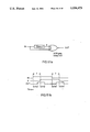
- FIG. 1 is a schematic block diagram of a Realizer hardware system.
- FIG. 2 is a schematic block diagram of a direct interconnect system.
- FIG. 3 is a schematic block diagram of channel-routing interconnect system.
- FIG. 4 is a schematic block diagram of a crossbar interconnect system.
- FIG. 5 is a schematic block diagram of a crossbar-net interconnect system.
- FIG. 6 is a schematic block diagram of a simple specific example of a partial crossbar interconnect system.
- FIG. 7 is a schematic block diagram of a partial crossbar interconnect system.
- FIGS. 8a and 8b illustrate a difference in crossbar chip width.
- FIG. 9 is a schematic block diagram of a tri-state net.
- FIG. 10 is a schematic block diagram of a sum-of-products equivalent to the tri-state net of FIG. 9.
- FIGS. 11a and 11b are schematic block diagrams of "floating low” and “floating high” sum of products networks.
- FIG. 12 is a schematic block diagram of drivers and receivers collected to minimize interconnect.
- FIG. 13 is a schematic block diagram of a logic summing configuration.
- FIG. 14 is a schematic block diagram of a crossbar summing configuration.
- FIG. 15 is a schematic block diagram of a bidirectional crossbar summing configuration.
- FIG. 16 is a schematic block diagram of a bidirectional crossbar tri-state configuration.
- FIG. 17 is a schematic block diagram showing off-board connections from partial crossbar.
- FIG. 18 is a schematic block diagram of Y-level partial crossbar interconnect.
- FIG. 19 is a schematic block diagram of a bidirectional bus system-level interconnect.
- FIG. 20 is a schematic block diagram showing eight boards on a common bus interconnect.
- FIG. 21 is a schematic block diagram showing the hierarchy of two bus levels.
- FIG. 22 is a schematic block diagram showing a maximum bus interconnect hierarchy.
- FIG. 23 is a schematic block diagram of a general memory module architecture.
- FIG. 24 is a schematic block diagram of a memory address logic chip.
- FIG. 25 is a schematic block diagram of a memory data logic chip using common I/O.
- FIG. 26 is a schematic block diagram of a memory data logic chip using separate I/O.
- FIG. 27 is a schematic block diagram showing multiple RAMs on one data bit.
- FIG. 28 is a schematic block diagram of a preferred embodiment of a memory module.
- FIG. 29 is a schematic block diagram of a stimulus vector memory.
- FIG. 30 is a schematic block diagram of a response vector memory.
- FIG. 31 is a schematic block diagram of a vector memory for stimulus and response.
- FIG. 32 is a schematic block diagram of a preferred embodiment of a vector memory address chip.
- FIG. 33 is a schematic block diagram of a preferred embodiment of a vector memory data chip.
- FIG. 34 is a schematic block diagram of random-access stimulators.
- FIG. 35 is a schematic block diagram of edge-sensitive stimulators.
- FIG. 36 is a schematic block diagram of samplers.
- FIG. 37 is a schematic block diagram of change-detecting samplers.
- FIG. 38 is a schematic block diagram of a user-supplied device module architecture.
- FIG. 39 is a schematic block diagram of a preferred embodiment of a USDM with devices installed.
- FIG. 40 is a schematic block diagram of a configuration group.
- FIG. 41 is a schematic block diagram of a host interface architecture.
- FIG. 42 illustrates RBus read and write cycles.
- FIG. 43 is a schematic block diagram of a Realizer design conversion system.
- FIGS. 44a and 44b illustrate design data structure used in the present invention.
- FIGS. 45a, 45b and 45c illustrate primitive conversion used in the present invention.
- FIG. 46 illustrates moving a primitive into a cluster.
- FIGS. 47a, 47b and 47c illustrate a simple net interconnection.
- FIGS. 48a, 48b and 48c illustrate tri-state net interconnection.
- FIG. 49 is a schematic block diagram of a Realizer logic simulation system.
- FIGS. 50a-c schematically illustrate Realizer system configuration of multi-state logic.
- FIGS. 51a-b schematically illustrate a delay-dependent functionality example.
- FIGS. 52a-c schematically illustrate a unit delay configuration example.
- FIGS. 53a-c schematically illustrate a real delay configuration.
- FIG. 54 is a schematic block diagram of a Realizer fault simulation system.
- FIG. 55 is a schematic block diagram of a Realizer logic simulator evaluation system.
- FIG. 56 is a schematic block diagram of a Realizer prototyping system.
- FIG. 57 illustrates a digital computer example on a Realizer prototyping system.
- FIG. 58 is a schematic block diagram of a virtual logic analyzer configuration.
- FIG. 59 is a schematic block diagram of a Realizer production system.
- FIG. 60 is a schematic block diagram of a Realizer computing system.
- FIGS. 61a-c illustrate the general architecture of the preferred embodiment, including the hierarchical interconnection of logic boards, boxes and rack.
- FIGS. 62a-b show the physical construction of a logic board box and a Z-level box.
- the Realizer hardware system (FIG. 1) consists of:
- a set of Lchips consisting of:
- At least two logic chips (normally tens or hundreds).
- one or more special-purpose elements such as memory modules and user-supplied device modules.
- a configurable interconnect connected to all LChip interconnectable I/O pins.
- a host interface connected to the host computer, the configuration system, and to all devices which can be used by the host for data input/output or control.
- a configuration system connected to the host interface, and to all configurable Lchip and interconnect devices.
- This hardware is normally packaged in the form of logic boards, boxes and racks, and is connected to and is operated under the control of the host computer.
- ERCGA electronically reconfigurable gate array
- a reconfigurable logic chip which is suitable for logic chips is the Logic Cell Array (LCA) ("The Programmable Gate Array Handbook", Xilinx, Inc., San Jose, Calif., 1989). It is manufactured by Xilinx, Inc., and others.
- This chip consists of a regular 2-dimensional array of Configurable Logic Blocks (CLBs), surrounded by reconfigurable I/O Blocks (IOBs), and interconnected by wiring segments arranged in rows and columns among the CLBs and IOBs.
- CLBs Configurable Logic Blocks
- IOBs reconfigurable I/O Blocks
- Each CLB has a small number of inputs, a multi-input combinational logic network, whose logic function can be reconfigured, one or more flip-flops, and one or more outputs, which can be linked together by reconfigurable interconnections inside the CLB.
- Each IOB can be reconfigured to be an input or output buffer for the chip, and is connected to an external I/O pin.
- the wiring segments can be connected to CLBs, IOBs, and each other, to form interconnections among them, through reconfigurable pass transistors and interconnect matrices. All reconfigurable features are controlled by bits in a serial shift register on the chip.
- the LCA is entirely configured by shifting in the "configuration bit pattern", which takes between 10 and 100 milliseconds.
- Xilinx 2000 and 3000-series LCAs have between 64 and 320 CLBs, with between 56 and 144 IOBs available for use.
- the LCA netlist conversion tool maps logic onto CLBs so as to optimize the interconnections among CLBs and IOBs.
- the configurability of interconnect between CLBs and the I/O pins gives the LCA the ability to freely connect I/O pins with the digital network, regardless of the particular network or which I/O pins are specified.
- the preferred implementation of the Realizer system uses LCA devices for its logic chips.
- ERCGA which is suitable for logic chips
- ERA electrically reconfigurable array
- a commercial example is the Plessey ERA60K-type device. It is configured by loading a configuration bit pattern into a RAM in the part.
- the ERA is organized as an array of two-input NAND gates, each of which can be independently interconnected with others according to values in the RAM which switch the gates' input connections to a series of interconnection paths.
- the ERA60100 has about 10,000 NAND gates.
- I/O cells on the periphery of the array are used to connect gate inputs and/or outputs to external I/O pins.
- the ERA netlist conversion tool maps logic onto the gates so as to optimize the interconnections among them, and generates a configuration bit pattern file, as described below.
- the configurability of interconnect between gates and the I/O cells gives the ERA the ability to freely connect I/O pins with the digital network, regardless of the particular network, or which I/O pins are specified.
- Still another type of reconfigurable logic chip which could be used as a logic chip is the EEPLD, or electrically erasable programmable logic device ("GAL Handbook", Lattice Semiconductor Corp., Portland, Oreg., 1986).
- GAL Lattice Generic Array Logic
- the GAL is organized as a sum-of-products array with output flip-flops, so it is less generally configurable than the Xilinx LCA. It offers freedom of connection of I/O pins to logic only among all input pins and among all output pins, so it partially satisfies that requirement. It is also smaller, with 10 to 20 I/O pins. It can, however, be used as a Realizer logic chip.
- Interconnect chips include crossbar chips, used in full and partial crossbar interconnects, and routing chips, used in direct and channel-routed interconnects.
- routing chips used in direct and channel-routed interconnects.
- the ERCGA devices discussed above namely the LCA, the ERA and the EEPLD, satisfy these requirements, so they may be used as interconnect chips. Even though little or no logic is used in the interconnect chip, the ability to be configured into nearly any digital network includes the ability to pass data directly from input to output pins.
- the LCA is used for crossbar chips in the preferred implementation of the Realizer system.
- Crossbar switch devices such as the TI 74AS8840 digital crossbar switch (SN74AS8840 Data Sheet, Texas Instruments, Dallas, Tex., 1987), or the crosspoint switch devices commonly used in telephone switches, may be used as interconnect chips.
- they offer a speed of reconfiguration comparable to the speed of data transfer, as they are intended for applications where the configuration is dynamically changing during operation. This is much faster than the configuration speed of the ERCGA devices. Consequently, such devices have higher prices and lower capacities than the ERCGAs, making them less desirable Realizer interconnection chips.
- the configuration bit patterns which are loaded into an ERCGA to configure its logic according to a user's specifications, are impractical for the user to generate on his own. Therefore, manufacturers of ERCGA devices commonly offer netlist conversion software tools, which convert logic specifications contained in a netlist file into a configuration bit pattern file.
- the Realizer design conversion system uses the netlist conversion tools provided by the ERCGA vendor(s). Once it has read in the design, converted it, partitioned it into logic chips, and determined the interconnect, it generates netlists for each logic and interconnect chip in the Realizer hardware.
- the netlist file is a list of all primitives (gates, flip-flops, and I/O buffers) and their interconnections which are to be configured in a single logic or interconnect chip.
- the Realizer design conversion system applies the ERCGA netlist conversion tool to each netlist file, to get a configuration file for each chip. When different devices are used for logic chips and interconnect chips, the appropriate tool is used in each case.
- the configuration file contains the binary bit patterns which, when loaded into the ERCGA device, will configure it according to the netlist file's specifications. It then collects these files into a single binary file which is permanently stored, and used to configure the Realizer system for the design before operation.
- the Realizer design conversion system conforms to the netlist and configuration file formats defined by the ERCGA vendor for its tool.
- Xilinx's LCA netlist conversion tool takes the description of a logic network in netlist form and automatically maps the logic elements into CLBs. This mapping is made in an optimal way with respect to I/O pin locations, to facilitate internal interconnection. Then the tool works out how to configure the logic chip's internal interconnect, creating a configuration file as its output result.
- the LCA netlist conversion tool only converts individual LCAs, and fails if the logic network is too large to fit into a single LCA.
- the Xilinx LCA netlist file is called an XNF file. It is an ASCII text file, containing a set of statements in the XNF file for each primitive, specifying the type of primitive, the pins, and the names of nets connected to those pins. Note that these nets are interconnections in the LCA netlist, connecting LCA primitives, not the nets of the input design. Some nets in the XNF file directly correspond to nets of the input design as a result of design conversion, others do not.
- these are the XNF file primitive statements which specify a 2-input XOR gate, named ⁇ I -- 1781 ⁇ , whose input pins are connected to nets named ⁇ DATA0 ⁇ and ⁇ INVERT ⁇ , and whose output pin is connected to a net named ⁇ RESULT ⁇ :
- IBUF Input and output I/O pin buffers
- OBUF Input and output I/O pin buffers
- the Xilinx LCA configuration file is called an RBT file. It is an ASCII text file, containing some header statements identifying the part to be configured, and a stream of ⁇ 0 ⁇ s and ⁇ 1 ⁇ s, specifying the binary bit pattern to be used to configure the part for operation.
- the interconnect consists of a combination of electrical interconnections and/or interconnecting chips. To realize a large design with the Realizer system, hundreds of logic chips, with a total of tens of thousands of I/O pins, must be served by the interconnect.
- An interconnect should be economically extensible as system size grows, easy and reliable to configure for a wide variety of input designs, and fast, minimizing delay between the logic chips. Since the average number of pins per net in real designs is a small number, which is independent of design size, the size and cost of a good interconnect should increase directly as the total number of logic chip pins to be connected increases. Given a particular logic chip capacity, the number of logic chips, and thus the number of logic chip pins, will go up directly as design capacity goes up. Thus the size and cost of a good interconnect should also vary directly with the design capacity.
- Nearest-neighbor interconnects are described in the first section
- Crossbar interconnects are described in the following section.
- Nearest-neighbor interconnects are organized with logic chips and interconnect intermixed and arranged according to a surface of two, three or more dimensions. They extend the row-and-column organization of a gate array chip or printed circuit board into the organization of logic chips. Their configuration for a given input design is determined by a placement and routing process similar to that used when developing chips and boards.
- Crossbar interconnects are distinct from the logic chips being interconnected. They are based on the many-input-to-many-output organization of crossbars used in communications and computing, and their configuration is determined in a tabular fashion.
- the interconnect In the direct interconnect, all logic chips are directly connected to each other in a regular array, without the use of interconnect chips.
- the interconnect consists only of electrical connections among logic chips. Many different patterns of interconnecting logic chips are possible.
- the pins of one logic chip are divided into groups. Each group of pins is then connected to another logic chip's like group of pins, and so forth, for all logic chips.
- Each logic chip only connects with a subset of all logic chips, those that are its nearest neighbors, in a physical sense, or at least in the sense of the topology of the array.
- All input design nets that connect logic on more than one logic chip either connect directly, when all those logic chips are directly connected, or are routed through a series of other logic chips, with those other logic chips taking on the function of interconnect chips, passing logical signals from one I/O pin to another without connection to any of that chip's realized logic.
- any given logic chip will be configured for its share of the design's logic, plus some interconnection signals passing through from one chip to another.
- Non-logic chip resources which cannot fulfill interconnection functions are connected to dedicated logic chip pins at the periphery of the array, or tangentially to pins which also interconnect logic chips.
- FIG. 2 A specific example, shown in FIG. 2, has logic chips laid out in a row-and-column 2-dimensional grid, each chip having four groups of pins connected to neighboring logic chips, north, south, east, and west, with memory, I/O and user-supplied devices connected at the periphery.
- each logic chip's pins are divided into 2*n groups. Each logic chip connects to 2*n other logic chips in a regular fashion.
- a further variation is similar, but the sizes of the pin groups are not equal.
- a dimension and set of pin group sizes is chosen that will minimize the number of logic chips intervening between any two logic chips while providing enough interconnections between each directly neighboring pair of chips to allow for nets which span only those two chips. Determining how to configure the logic chips for interconnect is done together with determining how to configure them for logic. To configure the logic chips:
- Partition and place the logic primitives in the logic chips In addition to partitioning the design into sub-networks which each fit with in a logic chip's logic capacity, the sub-networks should be placed with respect to each other so as to minimize the amount of interconnect required.
- Use standard partitioning and placement tool methodology such as that used in a gate-array or standard-cell chip automatic partitioning and placement tool ("Gate Station Reference Manual", Mentor Graphics Corp., 1987), to determine how to assign logic primitives to logic chips so as to accomplish the interconnect. Since that is a well-established methodology, it is not described further here.
- each routing direction there are as many channels in each routing direction as there are pins in each group of interconnected logic chip I/O pins. Since there are many possibilities for interconnection through the logic chips, the routing is not constrained to use the same channel at each end, with the same method as when many routing layers remove channel constraints in a gate array.
- the channel-routing interconnect is a variation of the direct interconnect, where the chips are divided into some which are not used for logic, dedicated only to accomplishing interconnections, thus becoming interconnect chips, and the others are used exclusively for logic, remaining logic chips.
- logic chips are not directly interconnected to each other, but instead connect only to interconnect chips.
- the channel-routing interconnect is composed according to the direct interconnect method. Nets which span more than one logic chip are interconnected by configuring a series of interconnect chips, called routing chips, that connect to those logic chips and to each other, such that logical connections are established between the logic chip I/O pins. It is thus used as a configurable ⁇ circuit board ⁇ .
- One example of a channel-routing interconnect is two-dimensional: logic chips are arranged in a row-and-column manner, completely surrounded by routing chips, as shown in FIG. 3.
- the array is made up of rows entirely composed of routing chips alternating with rows composed of alternating logic and routing chips. In this way, there are unbroken rows and columns of routing chips, surrounding the logic chips.
- the pins of each chip are broken into four groups, or edges, named "north, east, south and west.”
- the pins of each chip are connected to its four nearest neighbors in a grid-wise fashion: north pins connected with the northern neighbor's south pins, east pins connected with the eastern neighbor's west pins, and so forth.
- each logic chip's pins are divided into 2*n groups. Each logic chip connects to 2*n neighbors. There are (2**n-1) routing chips for each logic chip at the center of the array.
- the pins of the logic chips can be broken into any number of groups.
- the pins of the routing chips can be broken into any number of groups, which need not be the same number as that of the logic chip groups.
- the logic chips and routing chips need not have the same number of pins.
- Determining how to configure the interconnect chips is done together with determining how to configure the logic chips, with the same method used for the direct interconnect, with the exception that interconnections between logic chips are only routed through interconnect chips, not through logic chips.
- a net's logical signal passes through as many routing chips as are needed to complete the interconnection. Since each routing chip delays the propagation of the signal, the more routing chips a signal must pass through, the slower the signal's propagation delay time through the interconnect. It is desirable in general to partition the logic design and place the partitions onto specific logic chips in such a way as to minimize the routing requirements. If it is not possible to accomplish an interconnect, due to routing congestion, the design is re-partitioned and/or re-placed using adjusted criteria to relieve the congestion, and interconnect is attempted again. This cycle is repeated as long as necessary to succeed.
- the crossbar is an interconnection architecture which can connect any pin with any other pin or pins, without restriction. It is used widely for communicating messages in switching networks in computers and communication devices.
- the logic board of the preferred embodiment has 14 logic chips with 128 pins each to be connected, for a total of 1792 pins, far beyond the capability of any practical single chip. It is possible to construct crossbars out of a collection of practical interconnect chips, devices which can be configured to implement arbitrary interconnections among their I/O pins. In the context of crossbar interconnects, they are also called crossbar chips.
- FIG. 4 shows an example, extremely simplified for clarity.
- Four logic chips, with eight pins each, are to be interconnected.
- Crossbar chips with nine pins each are used.
- the left-most column of three crossbar chips connects logic chip 4's pin H with pins of logic chip 1, 2 and 3.
- the next column connects pin G, and so on to pin G of logic chip 4.
- the next eight columns of crossbar chips interconnect logic chip 3 with logic chips 1 and 2.
- Logic chip 4 is not included because its pins are connected to logic chip 3's pins by the first eight columns of crossbar chips.
- the final eight columns interconnect logic chips 1 and 2.
- a total of 48 crossbar chips are used.
- Net A is driven by logic chip 1, pin D, and received by logic chip 4, pin B.
- the crossbar chip marked 1 is the one which connects to both of those pins, so it is configured to receive from chip 1, pin D and drive what it receives to chip 4, pin B, thus establishing the logical connection.
- Net B is driven by chip 2, pin F and received by chip 3, pin G and chip 4, pin G.
- Crossbar chip 2 makes the first interconnection, and crossbar chip 3 makes the second.
- crossbar chips In general, the number of crossbar chips required can be predicted. If there are L logic chips, each with Pl pins, and crossbar chips, which each interconnect one logic chip pin with as many other logic chip pins as possible, have Px pins:
- Each pin of logic chip 2 must be connected to (L-2)Pl pins on logic chips 3 through L. This will require (L-2)Pl 2 /(Px-1) crossbar chips.
- crossbar interconnects are impractically large and expensive for any useful Realizer system.
- a crossbar-net interconnect is logically composed of two crossbars, each of which connects all logic chip pins with a set of connections, called interconnect nets (ICNs), numbering one half the total number of logic chip pins. Since a crossbar chip which connects a set of logic chip pins to a set of ICNs can also connect from them back to those pins (recalling the generality of interconnect chips), this interconnect is built with crossbar chips each connecting a set of logic chip pins with a set of ICNs.
- FIG. 5 shows an example, interconnecting the same four logic chips as in FIG. 4.
- Crossbar chips with eight pins each are used, and there are 16 ICNs.
- Each of the 32 crossbar chips connects four logic chip pins with four ICNs.
- Net A is interconnected by crossbar chip 1, configured to receive from chip 1, pin D and drive what it receives to an ICN, and by crossbar chip 2, which is configured to receive that ICN and drive chip 4, pin B, thus establishing the logical connection.
- Net B is driven by chip 2, pin F, connected to another ICN by crossbar chip 3, received by chip 3, pin G, via crossbar chip 4, and by chip 4, pin G, via crossbar chip 5.
- a crossbar-net interconnect for the preferred embodiment's logic board would require 392 crossbar chips with 128 pins each, or 1568 crossbar chips with 64 pins each.
- the crossbar-net interconnect uses fewer crossbar chips than the pure crossbar. Its size increases as the product of logic chips and total logic chip pins, which amounts to the square of the number of logic chips. This is better than the pure crossbar, but still not the direct scaling desired.
- the logic chip itself can offer an additional degree of freedom which crossbars do not exploit, because it has the ability to be configured to use any of its I/O pins for a given input or output of the logic network it is being configured for, regardless of the particular network. That freedom allows the possibility of the partial crossbar interconnect, which is the reason it is specified in the definition of the logic chip.
- the I/O pins of each logic chip are divided into proper subsets, using the same division on each logic chip.
- the pins of each crossbar chip are connected to the same subset of pins from each of every logic chip.
- crossbar chip ⁇ n ⁇ is connected to subset ⁇ n ⁇ of each logic chip's pins.
- each crossbar chip has as many pins as the number of pins in the subset times the number of logic chips.
- Each logic chip/crossbar chip pair is interconnected by as many wires, called paths, as there are pins in each subset.
- each crossbar chip is connected to the same subset of pins on each logic chip, an interconnection from an I/O pin in one subset of pins on one logic chip to an I/O pin in a different subset of pins on another logic chip cannot be configured. This is avoided by interconnecting each net using I/O pins from the same subset of pins on each of the logic chips to be interconnected, and configuring the logic chips accordingly. Since the logic chip can be configured to use any I/O pin may be assigned to the logic configured in a logic chip which is connected to a net, one I/O pin is as good as another.
- Each line connecting a logic chip and a crossbar chip in this figure represents a subset of the logic chip pins.
- Each crossbar chip is connected to a subset of the pins of every logic chip. Conversely, this implies that each logic chip is connected to a subset of the pins of every crossbar chip.
- the number of crossbar chips need not equal the number of logic chips, as it happens to in these examples. It does not in the preferred implementation.
- FIG. 7 shows an example, interconnecting the same four logic chips as in FIGS. 1 and 2.
- Four crossbar chips with eight pins each are used.
- Each crossbar chip connects to the same two pins of each logic chip.
- Crossbar chip 1 is connected to pins A and B of each of logic chips 1 through 4.
- Crossbar chip 2 is connected to all pins C and D, chip 3 to all pins E and F, and chip 4 to all pins G and H.
- Design net A was received on pin B of logic chip 4 in the previous examples, but there is no crossbar chip or chips which can interconnect this with the driver on pin D of logic chip 1. Since any I/O pin may be assigned to the logic configured in logic chip 4 which receives net A, pin C is as good as pin B, which may then be used for some other net. Consequently, net A is received by pin C instead, and the interconnection is accomplished by configuring crossbar chip 2.
- Design net B is received by chip 3, pin G, and by chip 4, pin G, but there is no crossbar chip or chips which can interconnect this with the driver on pin F of logic chip 2. Net B is driven by pin H instead, and the interconnection is accomplished by configuring crossbar chip 4.
- the partial crossbar interconnect is used in the preferred embodiment. Its logic board consists of 14 logic chips, each with 128 pins, interconnected by 32 crossbar chips with 56 pins each. Logic chip pins are divided into 32 proper subsets of four pins each, and the pins of each crossbar chip are divided into 14 subsets of four pins each. Each logic chip/crossbar chip pair is interconnected by four paths, as crossbar chip ⁇ n ⁇ is connected to subset ⁇ n ⁇ of each logic chip's pins.
- the partial crossbar uses the fewest crossbar chips of all crossbar interconnects. Its size increases directly as total number of logic chip pins increases. This is directly related to the number of logic chips and thus logic capacity, which is the desired result. It is fast, in that all interconnections pass through only one interconnect chip. It is relatively easy to use, since it is regular, its paths can be represented in a table, and determining how to establish a particular interconnect is simply a matter of searching that table for the best available pair of paths.
- Partial crossbar interconnects cannot handle as many nets as full crossbars can.
- the partial crossbar interconnect will fail to interconnect a net when the only I/O pins not already used for other nets on the source logic chip go to crossbar chips whose paths to the destination logic chip are likewise full.
- the destination may have pins available, but in such a case they go to other crossbars with full source pins, and there is no way to get from any of those crossbars to the first.
- the capacity of a partial crossbar interconnect depends on its architecture. At one logical extreme, there would be only one logic chip pin subset, and one crossbar would serve all pins. Such an arrangement has the greatest ability to interconnect, but is the impractical full crossbar. At the other logical extreme, the subset size is one, with as many crossbar chips as there are pins on a logic chip. This will have the least ability to interconnect of all partial crossbars, but that ability could still be enough. In between are architectures where each crossbar chip serves two, three, or more pins of each logic chip. More interconnect ability becomes available as the crossbar chip count drops and the pin count per crossbar chip increases.
- FIG. 8a In the first case (FIG. 8a), we use three crossbar chips, numbered 1, 2 and 3, which are each one pin wide. Each crossbar chip can only accommodate one net: crossbar chip 1 is programmed to interconnect net A, crossbar 2 connects net B, and crossbar chip 3 connects net C. Net D is left unconnected, even though there are free logic chip pins available.
- FIG. 8b In the second case (FIG. 8b), a full crossbar which is three pins wide is used instead of crossbar chips 1, 2 and 3, and net D may be connected.
- Narrow crossbar chips are much smaller, and therefore less expensive, pin-for-pin, than wide ones. Since they offer nearly as much interconnectability, they are preferred.
- an active interconnect such as the partial crossbar interconnect
- a passive one such as actual wire
- the active interconnect is unidirectional.
- Each interconnection actually consists of a series of drivers and receivers at the chip boundaries, joined by metal and traces. Normal nets have a single driver, and may be implemented with fixed drivers and receivers in the active interconnect. Some nets in actual designs are tri-state, with several tri-state drivers, as shown in FIG. 9.
- the network may be replaced by a two-state sum of products, or multiplexer, equivalent, as shown in FIG. 10.
- FIGS. 11a and 11b show both types of networks: "floating low” and "floating high.”
- the primitive conversion part of the Realizer system's design conversion system makes the sum or products substitution, because the Xilinx LCA, used for the logic and crossbar chips in the preferred implementation, does not support tri-state drive uniformly on all nets.
- Tri-state drivers are available on all I/O pins at the boundary of the LCA.
- a limited number of tri-state drivers are available internally in the XC3000 series LCAs, only on a small number of internal interconnects spaced across the chip, each of which serves only a single row of CLBs. Mapping tri-state nets onto those interconnects would add another constraint to partitioning, and could constrain the freedom of CLB placement on the LCA.
- tri-state connections with a small number of drivers per net are common in some gate array library cells. Consequently, the sum of products substitution is made when possible to avoid these complexities.
- FIG. 12 shows two drivers and two receivers collected together. The two drivers are collected by a local sum of products, which then contributes to the overall sum of products, requiring only a single driver connection. Likewise, only a single receiver connection is distributed across two receivers.
- the active interconnect comes into play.
- the "direction" of drive depends on which driver is active. While this makes no difference to a passive interconnect, an active interconnect must be organized to actively drive and receive in the correct directions. There are several configurations that accomplish this in the partial crossbar interconnect.
- the logic summing configuration places the summing OR gate in one of the logic chips involved, as shown in FIG. 13.
- the AND gates which generate the products are distributed in the driving logic chips, each of which needs an output pin.
- Each receiving logic chip needs an input pin, and the summing logic chip, which is a special case, will need an input pin for each other driver and one output pin.
- These connections are all unidirectional, involving an OBUF/IBUF pair across each chip boundary. Since there is a higher pin cost for drivers, a driving logic chip should be chosen as the summing chip.
- the actual path from a driving input pin through to a receiving output pin includes a CLB and OBUF on the driver, an IBUF/OBUF on the crossbar, and an IBUF, a CLB and an OBUF on the summing chip, another IBUF/OBUF on the crossbar, and an IBUF on the receiver.
- the crossbar IBUF delay Ix, the logic CLB delay Cl, etc. the total datapath delay is Cl+Ol+Ix+Ox+Il+Cl+Ol+Ix+Ox+Il.
- the logic chip is an XC3090-70
- the crossbar is an XC2018-70
- the maximum total delay is 82 ns, plus internal LCA interconnect delay. The same delay applies to the enable.
- n-bit bus If an n-bit bus is to be interconnected, all enables will be the same for each bit of the bus.
- the product gates are in the driving logic chips, the enables stay inside, and the pins required for the bus are just n times that for one bit.
- the summing OR gate is placed on the crossbar chip, making use of the fact that the crossbar chips in some embodiments are implemented with ERCGAs, such as LCAs, which have logic available, as shown in FIG. 14.
- Each logic chip needs one pin if it is a driver, and/or one pin if it is a receiver.
- the crossbar chip must have one or more logic elements for the summing gate.
- Crossbar summing deviates from the practice of putting all logic in the logic chips and none in the crossbar chips, but an important distinction is that the logic placed in the crossbar chip is not part of the realized design's logic. It is only logic which serves to accomplish the interconnection functionality of a tri-state net.
- This configuration uses fewer pins that the previous one when there are more than two driving logic chips.
- An n-bit bus takes n times as many pins. Total delay is reduced: Cl+Ol+Ix+Cx+Ox+Il, or 51 ns max. The enable has the same delay.
- the summing gate on the crossbar chip is reached via bidirectional connections in the bidirectional crossbar summing configuration, shown in FIG. 15.
- AND gates which allow only the enabled path into the OR gate are provided in the crossbar chip to block feedback latchup paths.
- a logic chip needs one pin if it is only a receiver, and two pins if it is a driver or both, one for the signal itself and one for the enable output, which is used by the crossbar chip.
- Reduced interconnect is possible for multi-bit busses by using a single enable for more than one bit. If more than one bit of the bus is interconnected through the same crossbar chip, only one set of enable signals need be provided to that chip.
- the total datapath delay is Ol+Ix+Cx+Ox+Il, or 42 ns in the preferred LCA embodiment. An additional Cx (10 ns) may be added if the sum of products takes more than one CLB.
- the enable delay will depend on the enable delay for the OBUFZ, El, instead of the output delay Ol.
- Each logic chip's actual tri-state driver is repeated onto the crossbar chip's bus, and should be accompanied by an interconnect for the enable signal.
- the crossbar chip's bus is driven back out when the driver is not enabled.
- the LCA were used as a crossbar chip, its internal tri-state interconnects described above would be used. Specifically, there is an IBUF/OBUFZ pair at the logic chip boundary, another IBUF/OBUFZ pair for each logic chip on the crossbar chip boundary, and a TBUF for each logic chip driving the internal tri-state line.
- Each enable passes through an OBUF and an IBUF.
- the total enabled datapath delay is Ol+Ix+Tx+Ox+Il, or 39 ns (XC3030-70 LCA crossbar), and the total enable delay is Ol+Ix+TEx+Ox+Il, or 45 ns.
- the crossbar be an LCA or other such ERCGA which has internal tri-state capability, and is subject to the availability of those internal interconnects.
- the XC2000-series LCAs do not have internal tri-state, but the XC3000 parts do.
- the XC3030 has 80 I/O pins, 100 CLBs, and 20 tri-state-drivable internal ⁇ long lines ⁇ . Thus a maximum of 20 such tri-state nets could be interconnected by one crossbar chip in this configuration. That could be the interconnect limitation, but only for a small fraction of cases, given the I/O pin limit.
- the XC3030 is twice as expensive as the XC2018 at this time.
- the logic summing configuration is clearly less effective.
- Crossbar summing is much faster and uses fewer pins, and is almost as simple.
- Bi-directional crossbar summing is slightly faster still, and offers the possibility of reduced pin count for bidirectional busses, but is more complex and places more demands on the limited logic resources in the crossbar chips.
- the tri-state configuration offers similar pin count and delay, but requires more expensive crossbar chips.
- the following chart shows the number of crossbar CLBs and crossbar CLB delays incurred when the plain and bi-directional crossbar summing configurations are used to interconnect a large number of bi-directional nets, and when LCAs are used for crossbar chips. It assumes XC2018-70 crossbar chips are used, which have 72 I/O pins and 100 CLBs available. Each CLB supports up to 4 inputs and up to 2 outputs. Each logic chip is assumed to have a bi-directional connection to the net, with no enable sharing, so each test case uses all 70 I/O pins in the crossbar chip.
- the bi-directional crossbar summing configuration uses up to 2.5 times as many CLBs, which increases the possibility that the crossbar chip won't route, or that the internal interconnect delays will be higher, although it stays well short of the 100 CLBs available.
- the unidirectional configuration puts more gates on the logic chips, although the logic chips are in a better position to handle extra gates.
- the bi-directional configuration incurs extra Cx delays more often, which can offset its speed advantage.
- the preferred embodiment of the Realizer system uses the crossbar summing configuration for all tri-state nets. 1.2.4. System-Level Interconnect
- a further constraint is that a single such interconnect is not expandable.
- each crossbar chip has connections to all logic chips. Once configured for a particular number of logic chips, more may not be added.
- logic board the largest complex of logic and crossbar chips which can be packaged together on a circuit board is used treated as a module, called a logic board, and multiples of these are connected by a system-level interconnect.
- additional off-board connections are made to additional I/O pins of each of the crossbar chips of each logic board, establishing logic board I/O pins (FIG. 17).
- the crossbar chip I/O pins used to connect to logic board I/O pins are different from the ones which connect to the board's logic chip I/O pins.
- One means of interconnecting logic boards is to reapply the partial crossbar interconnect hierarchically, treating each board as if it were a logic chip, and interconnecting board I/O pins using an additional set of crossbar chips.
- This partial crossbar interconnect s all the boards in a box.
- a third interconnect is applied again to interconnect all the boxes in a rack, etc. Applying same interconnect method throughout has the advantage of conceptual simplicity and uniformity with the board-level interconnect.
- the partial crossbar interconnect which interconnects logic chip is called the X-level interconnect, and its crossbar chips are called Xchips.
- the interconnect which interconnects logic boards is called the Y-level interconnect, and its crossbar chips are called Ychips.
- the I/O pins of each logic board are divided into proper subsets, using the same division on each logic board.
- the pins of each Ychip are connected to the same subset of pins from each of every logic board. As many Ychips are used as there are subsets, and each Ychip has as many pins as the number of pins in the subset times the number of logic boards.
- additional off-box connections are made to additional I/O pins of each of the Ychips, establishing box I/O pins, each of which are divided into proper subsets, using the same division on each box (FIG. 18).
- the pins of each Zchip are connected to the same subset of pins from each of every box. As many Zchips are used as there are subsets, and each Zchip has as many pins as the number of pins in the subset times the number of boxes. This method of establishing additional levels of partial crossbar interconnects can be continued as far as needed.
- the limited number of board I/O pins through which nets which may pass on and off a board is a constraint which is observed, just as a logic chip has a limited number of I/O pins.
- the limited number of box I/O pins is observed, and so on.
- the interconnect's symmetry means optimizing placement across chips, boards, or cardcages is not necessary, except so far as special facilities, such as design memories, are involved.
- Bidirectional nets and busses are implemented using one of the methods discussed in the tri-state section, such as the crossbar summing method, applied across each level of the interconnect hierarchy spanned by the net.
- the partial crossbar interconnect is used hierarchically at three levels across the entire hardware system.
- a logic board consists of up to 14 logic chips, with 128 interconnected I/O pins each, and an X-level partial crossbar composed of 32 Xchips. Each Xchip has four paths to each of the 14 Lchips (56 total), and eight paths to each of two Ychips, totalling 512 logic board I/O pins per board.
- a box contains one to eight boards, with 512 interconnected I/O pins each, and a Y-level partial crossbar composed of 64 Ychips.
- Each Ychip has eight paths to an Xchip on each board via logic board I/O pins, and eight paths to one Zchip, totalling 512 box I/O pins per box.
- a rack contains one to eight boxes, with 512 interconnected I/O pins each, and a Z-level partial crossbar composed of 64 Zchips. Each Zchip has eight paths to a Ychip in each box via box I/O pins.
- Some logic board I/O pins are wasted, i.e. unable to interconnect design nets, since the use of a bus wire for interconnecting one design net blocks off the use of pins connected to that wire on all the other boards sharing the bus.
- the maximum number of design nets which can be interconnected is equal to the bus wires, which equals the number of I/O pins per board. For a specific example, suppose eight boards share a common interconnect bus, with 512 bus wires connecting the 512 I/O pins of each board (FIG. 20).
- the first example shown in FIG. 21 has two sets of busses, X0 and X1, connecting four boards each.
- the X-level busses are interconnected by another bus, Y.
- Each wire in an X bus can be connected to its counterpart in Y by a reconfigurable bidirectional transceiver, whose configuration determines whether the X and Y wires are isolated, driven X to Y, or Y to X.
- a net connects only the left set of boards or the right set of boards, then only one or the other of the X-level busses is used.
- a wire in each of X0 and X1 is used, and these wires are interconnected by a wire in Y, via the transceivers.
- Each board should have as many I/O pins as the width of one of the X-level busses.
- interconnection through Y is to be bidirectional, that is, driven from either X0 or X1
- an additional signal should be passed from X0 and X1 to dynamically control the transceiver directions.
- This interconnect has been analyzed to show its capability for interconnecting nets among the boards, making the same net pin count and I/O pin count assumptions as above. While the single-level method requires the same width as the total number of all nets, breaking it into two decreases the maximum width required by 10 to 15%.
- the maximum amount of hierarchy has only two boards or groups of boards per bus (FIG. 22).
- Bidirectional bus interconnects are simple and easy to build, but they are expensive, because a large number of logic board I/O pins are wasted by connecting to other boards' nets. Introducing hierarchy and short backplanes to avoid this proves to have very little effect. In addition, the introduction of bidirectional transceivers removes a speed and cost advantage that the single-level backplane bus interconnect had over a partial crossbar. Consequently, partial crossbars are used in the system-level interconnect of the preferred embodiment.
- Special-purpose elements are hardware elements which contribute to the realization of the input design, and which are installed in Lchip locations on the logic board of the preferred embodiment, but which are not combinational logic gates or flip-flops, which are configured into logic chips.
- the architecture of a design memory module is derived from requirements:
- FIG. 23 The general architecture of a memory module that satisfies these requirements is shown in FIG. 23.
- the memory module is designed to plug into an Lchip socket, connected to the same interconnect and other pins as the logic chip it replaces. As many modules as needed are installed.
- RAM chips are not directly connected to the interconnect, mainly because their data, address and control functions are fixed to specific pins. Since the success of the partial crossbar interconnect depends on the logic chip's ability to freely assign internal interconnects to I/O pins, non-logic chip devices installed in a logic chip's place should have a similar capability. To accomplish this, and to provide for other logic functions in the memory module, logic chips are installed in the memory module, interconnecting the RAM chips with the crossbar's Xchips.
- RAM pins are configured to interconnect specific RAM pins with arbitrarily chosen Xchip pins, using the same L-X paths used by the logic chip whose place the memory module has taken. More than one logic chip is used per module because of the large numbers of RAM pins and L-X paths to be connected.
- An additional function of the memory module's logic chips is to provide it with configurability and host accessibility. Address, data and control paths are configured through the logic chips to connect the RAM chips in a variety of capacities, bit widths and input/output structures.
- the memory module may be configured as one large memory or several smaller ones. By connecting each of these logic chips to the host interface bus, and by configuring bus interface logic in them, functionality is realized which allows the host processor to randomly access the RAMs, so a user's host computer program, such as a debugger, can inspect and modify the memory contents. Examples of these logic structures are shown below.
- CMOS SRAM complementary metal-oxide-semiconductor
- Fujitsu MB84256 the 32K by 8 bit CMOS SRAM, such as the Fujitsu MB84256. It is available at speeds down to 50 ns. Much faster devices offer diminishing returns, as the Realizer system's crossbar chip interconnect delays start to predominate.
- Dynamic memory devices are not used because they must be refreshed regularly, which would present problems in the Realizer system. If the input design calls for a dynamic memory, presumably it includes refresh logic. However, since the realized design may not be operating at 100% of design speed, letting the design do the refresh may not be successful. In fact it is desirable to stop the design's operation altogether when debugging. Or, the design may be part of a system which depends for refresh on some other element, not included in the input design. Finally, if the design calls for static memory, refresh of a dynamic design memory would be impractical. A static memory can realize a dynamic memory in the design, as refresh cycles may just be ignored. Thus the design memory is implemented with static devices.
- a single logic chip would be used to interconnect RAMs with the X-level crossbar, with enough pins to connect to all RAM signal pins as well as all L-X interconnect paths.
- Practical Realizer system memory modules require far too many pins for a single logic chip to fulfill. For example, suppose 2 banks of eight 32K by 8 bit RAMs were used in a module with 128 L-X paths. Each RAM bank would have 15 address pins, 8 write enable pins, and 64 data pins. Two banks and the L-X paths would require 302 pins, plus pins for the host interface bus. This outstrips the pin count of available logic chips by a factor of two. More than one logic chip must be used.
- the architecture described here uses a number of small logic chips, which are given specialized functions, some for address and control, and others for the data paths.
- Address and control logic chips are marked “MA0" and "MA1" in FIG. 23.
- the RAMs are split into banks, one controlled by each MA chip. There are as many MA chips as the maximum number of separate design memories to be realizable by the module. Each is given its own set of L-X paths to the crossbar, as many paths as needed for one bank's address and control lines. MA0 and MA1 use a different set of paths. For example, two MA chips, each connected to half the RAMs, allows two independent memories to be realized. If one larger memory is to be realized, the address and control nets are interconnected to both MA chips, using both sets of L-X paths. Each MA chip controls the address inputs of all RAMs in its bank, which are tied together in a single bus. Each MA chip individually controls the control inputs to the RAMs, to allow for data to be written into only the addressed RAM(s). Finally, each MA chip is connected to the host interface bus for accessibility, and to a control bus common to all logic chips on this memory module.
- FIG. 24 shows in greater detail how an MA chip is connected to X-level crossbar and to the RAM chips.
- the MA chip is configured according to the logic and data paths as shown.
- the full address enters the MA chip from the crossbar. Normally (when the bus interface is inactive), a fraction of address bits corresponding to the number of RAM address bits is passed on to address the RAMs in the bank controlled by this MA chip.
- the other address bits and the design's write enable drive decoder logic which controls the write enable signals for each RAM.
- This logic is configured according to the configuration needed for this design memory. For example, if the design memory has the same bit width as one of the RAMs, when the design asserts its write enable only a single RAM write enable will be asserted, according to the address bits. If the design memory is twice as wide as one chip, then a pair of RAM write enables will be asserted, and so on.
- design memory with more than one write enable, each controlling a subset of the memory's data path width, is desired, several design write enable nets may be used, each operating along the lines described above, with suitable configuration of the decode logic in the MA and MD chips. This is subject to the availability of L-X paths into the MA chip and control bus paths into the MD chips.
- the bus interface logic allows the host to access this RAM via the host interface bus.
- the bus interface switches the address multiplexer ( ⁇ mux ⁇ ) to address the RAMs with its address.
- the bus interface logic sends a signal to the decoder logic, which uses the address bits not driving the RAMs to assert the appropriate RAM write enable.
- a control bus is connected to all MA and MD chips to allow these signals, and bus interface control signals, to be sent to the MD chips.
- MD chips handle the data paths according to a bit-slice organization. Multi-bit bus data paths are interconnected in the Realizer system by being bit-sliced across the crossbar. Busses are spread out across the Xchips, with one or two bits per chip. MD chips are bit-sliced to facilitate connection to these busses. Each MD chip is connected to the same bit or bits of every RAM in all banks, and to a subset of Xchips. Bringing all the like RAM bits together in the MD chip allows flexibility in configuring design memories of various bit widths and sizes. Design memories are realized in various multiples of the RAM width by suitably configuring logic and data paths in the MD chip.
- each MD chip When there are ⁇ n ⁇ MD chips and ⁇ M ⁇ Xchips, each MD chip connects with M/n different Xchips. Each data bit requires two L-X paths; either a DI and a DO path for separate I/O configurations, or the summing input and summing result for common I/O bidirectional configurations, due to the crossbar summing interconnect configuration. Thus, each MD chip has at least 2*M/n L-X paths. Additional paths may be added beyond this, and may overlap with MA's L-X paths.
- the number of MD chips, RAMs and RAM bit widths are chosen to suit these constraints and capacity constraints, to efficiently use the number of pins in the logic chip used for the MD chip, and to come out even.
- the industry-standard static RAM chip has a common I/O structure, with bidirectional data pins (named DQ), used for data in and tri-state data out. It has address input pins (ADDR), and a write enable pin (WE).
- DQ bidirectional data pins
- ADDR address input pins
- WE write enable pin
- the output enable pins and chip select pins are permanently enabled in this implementation, so the output pins are controlled by write enable. When disabled, the RAM is reading, and the addressed data is driven out on the DQ pins. When write enable is asserted, data in is received on the DQ pins. On the trailing edge of the assertion, data is written into the address location.
- the standard device only requires data in setup to the trailing edge of write enable, and requires zero hold time, so write enable control of datapaths is acceptable.
- the driving pins are separately gated by their enables and collected into a summing OR gate, which drives the receiving pins.
- the RAM DQ data pins are interfaced by logic and data paths configured in the MD chips as shown in FIG. 25 (one bit, bit ⁇ n ⁇ , is shown, others similar).
- Each MD chip (MD ⁇ n ⁇ shown) is configured with an enable gate driving a summing gate in the Xchip, just as an Lchip has an enable gate driving a summing gate in the Xchip when it has a tri-state driver.
- the logic gates the RAM output into the summing gate and disables the receiving driver. Otherwise, the net value is driven from the summing gate into the RAM, allowing writing when write enable is asserted.
- the design write enable and output enable signals come from the MA chip (over the control bus), as discussed above. Bus interface logic is not shown.
- the above figures only show one RAM connected to a design data bit. Often there will be several, when the number of locations in the design memory is to be a multiple of the size of a single RAM chip. In such cases, the MD chip is configured as shown in FIG. 27.
- a DQ pin from each of several RAMs is connected to this MD chip.
- Low address bits and the design and bus interface control signals are carried to the MD chips over the control bus from the MA chip.
- the low bits of the address select one of the RAM DQ outputs through the multiplexer.
- the selected output is gated by the design output enable to form the design memory data out, as in the previous case.
- the design asserts its write enable
- the data in is driven to one of the RAM DQ inputs by enabling a driver.
- Decode logic driven by the low address bits and the design write enable signal, selects the appropriate driver to be driven. Recall that the RAM chip's write enable is driven by the MA chip.
- FIG. 27 shows a separate I/O configuration.
- a common I/O configuration would be similar, with data in driven by the crossbar summing gate and data out gated by design output enable and write enable and driving a summing gate input, as in FIG. 25.
- bus read enable drives the data, selected from the addresses RAM by the multiplexer, onto the host interface bus data bit corresponding to this MD chip.
- bus writes data from the bus data bit is switched onto the drivers by another multiplexer. It is driven onto the DQ pin of the RAM selected by the same process as normal writes.
- MD chip configurations with a single data bit out of a single design memory's data path width. If called for by the design memory configuration, and the number of MD and RAM chips in the module, more than one data bit may appear in each MD chip, simply by replicating the data paths as appropriate. Additionally, more than one design memory may be implemented using a common set of MD chips by replicating the above data paths and control lines to implement several memories.
- Design memories are specified in the input design by using a design memory RAM primitive corresponding to one of the available configurations in the original design file.
- the design conversion method is based on a set of pre-defined partial netlist files, one for each of the memory module's logic chips, with statements for all the logic and data paths to be configured for the particular memory configuration specified, as shown above.
- the pre-defined files are complete, except for I/O pin number specifications for the module I/O pins which are used to connect the design memory address, data and control connections with the interconnect.
- I/O pin number specifications for the module I/O pins which are used to connect the design memory address, data and control connections with the interconnect.
- the design reader reads the memory primitive for the specified vector memory into its design data structure.
- the data specifying which configuration to use is stored in the data structure record for the memory.
- the conversion stage checks to see that the configuration is available and the pins correspond to the configuration correctly.
- the partitioner is told by the user which Lchip positions on which boards have memory modules installed. Based on that data, it selects a memory module for the memory according to its normal partitioning algorithm. Alternatively, the user can assign the memory to a particular module by associating that data with the primitive in the original design file, which is included in the memory's primitive record by the design reader.
- the interconnector then assigns nets and pins connected to the memory to specific L-X interconnect paths. It does this subject to the constraints that address and control nets may only be assigned certain paths which connect to the MA chip, and data nets may only be assigned to paths which connect to the MD chip. These constraints are applied during interconnection when determining each crossbar chip set's ability to interconnected the net, rejecting those sets and not scoring or using those paths which do not connect to the required MA or MD chip.
- each design memory net connection is netlisted by:
- the netlist files are processed into configuration bit patterns by the netlist conversion tool and loaded into the logic chips just like the netlist files for Lchips and Xchips.
- FIG. 28 shows the design of the memory module used in preferred embodiment. Note that it is architected according to the organization described above and shown in FIG. 23. It is designed to be plugged into an Lchip socket in place of an XC3090 LCA logic chip. Thus there are 128 L-X paths, 4 paths to each of 32 Xchips.
- 32K by 8 bit static RAM chips with common I/O are used, in two banks of 8 RAMs each.
- Each bank has its own MA chip, an XC2018 LCA.
- Each MA chip controls its RAMs with 15 address paths and 8 write enables. It is connected to the control bus common to all MA and MD chips in the module, and to the host interface bus. The remaining pins connect to the crossbar.
- 28 L-X paths, each to a different Xchip, are provided.
- MA chip 0 uses one set of paths, path 0, and MA1 uses path 1, allowing separate address and control nets for two independent design RAMs. Fewer than the full 32 L-X paths are connected only because of pin limitations in the XC2018.
- the path elements in the interconnecter's L-X path table corresponding to the missing L-X paths on this module are marked unavailable, so nets are not interconnected through them.
- An additional two paths to each Xchip are provided to allow the module to be used as a 128 bit vector memory, as discussed below.
- the host interface bus implemented in the preferred embodiment is called the Rbus, which connects to all Lchip positions via additional pins, and which is described in the host interface section.
- path 0 means one set of L-X paths, one from each Xchip, "path 1" means another set, etc.
- the control bus consists of 12 paths connected to all MA and MD chips in common. 12 paths are required to support the maximum control configuration, which is 3 address bits, design write enable, and design output enable signals for each of two 256K by 8 bit design memories, plus the bus write enable and bus read enable.
- Realizer system Many uses of the Realizer system depend on the host computer sending stimulus signals and collecting response signals to and from the design. When this is done in batch form, that is sending and collecting a large body of signal at once, vector memories are used. When it is done one signal at a time, stimulators and samplers are used.
- FIG. 29 shows a means of accomplishing such a stimulus vector memory.
- a regular clock signal, ECLK controls the process.
- ECLK is cycled, that is brought high and then low, once for each stimulus vector.
- a binary counter provides the sequence of addresses. When ECLK is brought high, the counter counts up to the address of the next stimulus vector, which is read by the RAM during the ECLK cycle. When ECLK is next brought high, the stimulus vector value just read is clocked into a D flip-flop. The output of the flip-flop drives the net to be stimulated with the stimulus vector value. The flip-flop provides a clean transition between vectors, which is necessary since the RAM output may fluctuate during its read cycle before it stabilizes at the correct value. This process is repeated to present the series of stimulus vectors to the realized design.
- one mode of collecting response from the realized design is to collect a continuous stream of samples, or vectors, from a set of nets, as a logic analyzer does from actual hardware devices. This is done by interfacing a memory to nets in the realized design, sequentially writing vectors from the nets into the memory as the realized design is operated, and finally reading the collected response vectors back into the host computer for analysis. Since a continuous, linear series of memory locations is to be read, the address stream is provided by a binary counter, as before. FIG. 30 shows a means of accomplishing such a response vector memory.
- a clock signal controls the process. ECLK is cycled once for each response vector.
- the binary counter provides the sequence of address. When ECLK is brought high, the counter counts up to the address of the next vector.
- the response vector value is driven onto the RAM DQ data pin by the tri-state driver and the RAM is enabled for writing.
- ECLK is brought high again, the value is written into the RAM location, the RAM write enable and tri-state driver enable are disabled, and the counter advances to the address for the next vector. This process is repeated to record the series of response vectors from the realized design.
- the realized design is also being stimulated to produce these responses. If the stimulus is coming from a stimulus vector memory, then both vector memories will use the same ECLK signal.
- the ECLK signal should be high for long enough for the new address to pass from the counter, address the RAM, and for data to be read and set up on the stimulus D flip-flop inputs. It should then be low for long enough for the stimulus to affect the realized design and for all responses of that effect to stabilize, and for those responses to be written into the RAM. If the stimulus is coming from elsewhere, then the response vector memory's ECLK signal should be synchronized with the realized design so as to sample the response nets correctly.
- RAM bits may be freely assigned to either stimulus or response, even if they are on the same RAM device, because the stimulus reading function occurs when ECLK is high, and the response writing function follows when ECLK is low.
- An important difference between the simple stimulus vector memory and the combined stimulus/response vector memory is that the stimulus vectors may be read out of the RAM only once, since each memory location is written to in the low half of the ECLK cycle, even when the RAM bit is used for stimulus only. This can be avoided only if all bits of a RAM chip are used for stimulus, and the write enable is not asserted by ECLK.
- the Realizer Fault Simulation System is discussed in the section on that topic.
- response is not collected in vector memories, but instead is compared with pre-determined good-circuit response by a fault-response vector memory. It is the same as a simple stimulus vector memory, as shown above, with the following additions:
- the output is compared against the value of the net by an XOR gate.
- the XOR gate is connected to a set flip-flop clocked by ECLK, such that if it ever goes high, indicating a difference between the net and memory, the flip-flop is set. This set flip-flop is readable by the host through the host interface to see if a difference has been detected.
- Realizer systems can be built with the vector memory connected directly to one or more logic chips and/or connected to any or all of the interconnect paths.
- vector memories can be installed on the logic board along with the Lchips and Xchips, and connected to the X-Y paths coming off the board.
- Another possibility is to install vector memories on the Y-level crossbar's Ychip board, connected to the X-Y and Y-Z paths.
- Another technique is to install the vector memory in an Lchip location, in place of a logic chip, connected to the L-X paths that serve the Lchip location. In this case, these L-X paths are connected only between the vector memory and the Xchip. Connection to nets in the realized design is made by configuring the Xchips to connect the vector memory to the nets as they pass through the X-level interconnect. Replacing logic chips with vector memory modules can be done in a modular way, allowing the Realizer hardware to be configured with as many or as few vector memories as necessary. Since Realizer design memory modules also are installed in place of one or more logic chips in Lchip locations, using this technique allows the a common hardware memory module to be used as a design memory module or as a vector memory module. The choice of function is made by configuring the logic chips in the memory module and the Realizer system interconnections appropriately. This is the vector memory architecture used in the preferred embodiment.
- a common memory module is used for both design memory and vector memory applications. Its general architecture and design are discussed in the section on design memory and will not be discussed here. The details of how the module is configured for vector memory use follow.
- the following two figures show the way logic in the MA and MD chips are configured for a combined stimulus/response vector memory, with full read/write access from the host interface.
- the host interface is inactive, all operation is according to the same techniques shown in the simplified examples above.
- the ECLK signal generated by the host via the host interface, is interconnected into the MA chip(s) via the interconnect. It clocks the address counter, which is configured in each MA chip. As there are more than one MA chip in a module, each controlling a subset of the RAMs, each MA chip has its own copy of the vector memory address counter. Since all counters get the same controls (ECLK, and a reset signal from the Bus Interface), each will always issue the same address as the others. Normally (when the bus interface is inactive), the address is passed from the counter out to address the RAMs. When ECLK is low (write response phase), the decoder logic asserts all RAM write enables, as in the previous examples. ECLK is also driven onto the Control Bus to drive logic on the MD chips.
- the MD logic handles the stimulus and response vector values themselves (FIG. 33). Normally (when the bus interface is inactive), when ECLK is high the RAMs are reading out stimulus vector values, and as ECLK falls they are clocked into flip-flops, one for each net to be stimulated (one shown), as above. The stimulus is then driven onto the nets via the interconnect's Xchips. When ECLK is low, all tri-state enables (e0, e1, . . . en) are asserted so as to drive the response values coming in from the nets via the interconnect (two shown) onto the RAM DQ data pins, through the multiplexers.
- the bus interface logic configured in each MA chip becomes active. It switches the address multiplexer (mux) so that the bus addresses the RAMs. If the bus cycle is to write the RAMs, the decoder logic uses the address bits to decode which RAM is to be written and asserts the appropriate write enable signal. The address bits needed to select RAMs and the read and write control signals are also passed across to the MD chips via the Control Bus.
- the decode logic disables all tri-state RAM DQ pin drivers, address bits are used to select the addressed RAM's DQ data output through the read multiplexer, and the bus read enable signal drives the data value onto the host interface bus' data line for this bit.
- the decode logic uses the write multiplexers to select the data value coming in from the host interface bus' data line instead of the nets giving response, and enables the tri-state RAM DQ driver for the addressed RAM, driving the data onto the RAM input.
- the design conversion method is based on a set of pre-defined partial netlist files, one for each of the module's logic chips, with statements for vector memory stimulus and response connections, vector memory data paths and control logic, and bus interface logic, as shown above.
- This method assumes the ERCGA netlist conversion tool will not configure logic and interconnections for primitives and nets in the netlist file which are not usefully connected, such as inputs unconnected to any outputs or I/O pins, and outputs not connected to any inputs or I/O pins. There is logic provided for a stimulus connection and a response connection for each vector memory bit. Only the one for which interconnections are issued to the netlist will actually become configured; the other will not because it will not be usefully connected in the netlist.
- the pre-defined files are complete, except for I/O pin number specifications for the module I/O pins which are used to connect the vector memory stimulus and response connections with the interconnect.
- the number of stimulus and response connections in each file is determined by how many I/O pins are available in the file's logic chip, and by how much logic can be accommodated each chip and by the module as a whole. The method follows:
- the design reader reads the property information from the input design file identifying nets marked for vector memory connections, and puts one or more vector memory primitives, connected to the nets but not to the bus interface logic, into its design data structure. It also creates the ECLK net, connected to the host interface clock generator and to all vector memory primitives.
- the partitioner is told by the user which Lchip positions on which boards have memory modules installed. Based on that data, it partitions the vector memory primitives into the memory modules in the normal way.
- the interconnector treats the vector memory primitives identically to other logic chip primitives, determining L-X paths which connect them with the other primitives on their nets.
- each vector memory net connection is netlisted by:
- the design conversion system also issues a correspondence table file, relating net names with vector memories and vector memory bit positions, for use during operation.
- the ERCGA netlist conversion tool only configures the logic and interconnections for the vector memory stimulus and response inputs which are used.
- a stimulator is a single bit of storage, controlled by the host computer and driving a net in the design. It is used by the host to provide input signals to the design.
- the random-access stimulator is simply a flip-flop whose output drives the design net into which data can be loaded on demand by the host, via the host interface bus. It is used for stimulating nets which may change value any time relative to other stimulated nets without changing the operation of a design.
- An example of such a net is the data input to a register.
- Each stimulator has a unique bus address, and when the host writes data to that address, the bus interface logic applies the data to the D input and cycles the stimulator flip-flop's clock input (FIG. 34).
- the edge-sensitive stimulator is used for stimulating nets whose changes must be synchronous with other such nets for correct operation of a design, for example, the clock inputs to registers.
- a second flip-flop is interposed between the output of a random-access stimulator and the design net. All such flip-flops in a group of stimulators which must be synchronized are connected to a common clock.
- the host loads new values into the first flip-flop of each stimulator via the host interface bus in any order, as above.
- the host cycles the common ⁇ sync clock, ⁇ loading all values into the second flip-flops at once, thus driving all nets at once (FIG. 35).
- a sampler is a single bit of storage, controlled by the host computer and receiving a net in the design. It is used by the host to collect output signals from the design.
- sampler The simplest form of sampler is a flip-flop which receives the design net on its D input, and which can be clocked and read on demand by the host, via the host interface bus and bus interface logic.
- samplers are connected to a common ⁇ sample clock ⁇ .
- Sampler data outputs have unique bus addresses, as does the ⁇ sample clock ⁇ output.
- the host cycles the clock to take a group of samples, and then reads the sampled data values one by one (FIG. 36).
- a second flip-flop is optionally added to make a change-detecting sampler.
- the second flip-flop is connected to the same clock as the sampling flip-flop, and its input is connected to the sampler's output. As a result it contains the value the sampler had before the most recent clock cycle.
- the two flip-flop outputs are compared by an XOR gate, which will output a high value when the two flip-flops differ because of a change in sampled value. All XOR outputs from a group of samplers are summed together by an OR gate, which is readable by the host.
- the host After sampling the nets by cycling the ⁇ sample clock ⁇ , as above, the host checks this OR gate ⁇ change ⁇ value first to see if any values in the group have changed. If not, it does not need to read any of those sampler values (FIG. 37).
- the sampler and stimulator flip-flops, logic gates and bus interface logic are realized in Realizer system logic chips.
- the user marks the net with a special property in the input design, specifying the specific type of stimulator or sampler and group identification.
- a general methodology for the design conversion software system to use for configuring the stimulators and samplers and connecting them to the rest of the design and to the bus interface is as follows:
- the design reader reads the property information from the input design file identifying nets marked for stimulators and/or samplers, and puts stimulator and sampler primitives, connected to the nets but not to the bus interface logic, into its design data structure.
- the system partitioner has a data base of how many gate-equivalents each such primitive accounts for in a logic chip. It also has a gate-equivalent figure for the bus interface logic. Based on that data, it assigns the stimulators and samplers to logic chips according to its normal partitioning algorithm, with the additional condition that it lowers its logic capacity limit by the size of the bus interface logic, to account for the fact that each logic chip with one or more stimulators and/or samplers must have a bus interface logic block.
- the interconnector treats the stimulator and sampler primitives identically to other primitives.
- each sampler or stimulator primitive is netlisted with the following procedure:
- a pre-defined netlist file segment for the bus interface is used to issue the primitives and nets that will configure the bus interface into the logic chip.
- the bus interface net connections which are used only once per interface are given standard names defined in that file segment. Those which are connected to the stimulator or sampler logic are given derived net names coordinated with the names used when issuing the primitives in step 1.
- a simpler but less general methodology realizes stimulators and samplers only in the logic chips of a memory module or user-supplied device modules. It assumes the ERCGA netlist conversion tool will not configure logic and interconnections for primitives and nets in the netlist file which are not usefully connected, such as inputs unconnected to any outputs or I/O pins, and outputs not connected to any inputs or I/O pins. It is based on a set of pre-defined partial netlist files, one for each of the module's logic chips, with statements for the following:
- the pre-defined files are complete, except for I/O pin number specifications for the module I/O pins which are used to connect the samplers and stimulators with the interconnect.
- the control bus is used to distribute common signals, such as the sync and sample clocks, among the logic chips.
- the number of stimulators and samplers in each file is determined by how many I/O pins are available in the file's logic chip, and by how much logic can be accommodated each chip and by the module as a whole. The method follows: Normal methods are used for design conversion, as described in the design conversion sections, with special exceptions for stimulators and samplers as follows:
- the design reader reads the property information from the input design file identifying nets marked for stimulators and/or samplers, and puts stimulator and sampler primitives, connected to the nets but not to the bus interface logic, into its design data structure.
- the partitioner is told by the user which Lchip positions on which boards have memory modules and user-supplied device modules installed. Based on that data, it assigns memory and USD primitives to the modules first, then partitions stimulator and sampler primitives into the remaining such modules according to its normal partitioning algorithm, up to the limit of the number available per module.
- the interconnector treats the stimulator and sampler primitives identically to other logic chip primitives, determining L-X paths which connect them with the other primitives on their nets.
- each sampler or stimulator primitive is netlisted by:
- the ERCGA netlist conversion tool only configures the logic and interconnections for the stimulators, samplers and related bus interface logic which are used.
- the design conversion system also issues a correspondence table file, relating net names with specific stimulator and samplers and corresponding addresses on the host interface bus, for use during operation.
- the input design is realized in actual working hardware in the form of configured logic and interconnection chips, it is practical and desirable to connect other actual hardware devices to the Realizer system.
- These may be any devices with digital inputs and outputs, such as microprocessor or other VLSI IC chips, digital/analog converters, display devices, input keyboards and switches, storage devices, computer input/output busses, etc.
- These may also be parts of digital systems, such as circuit boards or larger scale components, of which the realized design is a part.
- These devices represent the part of the input design to be realized which cannot be implemented in the Realizer system's logic gates, flip-flops and memories, either for physical reasons, such as a display, because of a lack of sufficient Realizer system resources, such as a mass storage device, or because the logical description is not available, such as a standard microprocessor.
- they may represent devices which the user does not want to realize with Realizer system resources, such as a semicustom gate array chip which has been fabricated and is known to be correct, because there is no need to consume Realizer system resources to implement it, or because the user wishes to test whether the realized part of the design operates correctly with it. Since they are not part of all Realizer systems, but instead are supplied by the user according to the needs of his designs, these devices are called “user-supplied devices" (USD).
- USD user-supplied devices
- USDM user-supplied device module
- the user-supplied device module :
- FIG. 38 shows the USDM architecture.
- Devices are installed on the user-supplied device installation area, which can be an area of the USDM printed circuit board, a removable daughtercard plugged into the USDM, or another such area connected via cable in the manner common in microprocessor emulator instruments.
- a terminal block provides a means for making electrical connections between device input and output pins and the USDM logic chips, through a connector, terminal strip, set of printed circuit board pads, or other such means. It also may provide electrical power for the devices.
- One or more devices may be installed as physical and terminal block pin capacity permits. Alternatively, devices may be connected remotely via cabling and repeater devices in the common manner.
- Each MA and MD logic chip has some I/O pins connected to the terminal block, and some connected to the interconnect. These chips are connected to the interconnect in the same manner described for memory module address and data path logic chips. Optionally, they may also be connected to the host interface bus and/or a common control bus, for purposes similar to their uses in memory modules, as shown.
- USD address and data busses are normally connected to the MD chips in a manner such that the bus data bits are distributed across the MD chips, and thus across the interconnect.
- the MA chips are used for USD control lines and optionally for USD address lines.
- the figure shows three hypothetical user devices connected to illustrate possibilities.
- USD0 has its data and address busses connected via the MD chips and its control lines, A, B and C, connected via MA0.
- USD1 has three data busses connected to the MD chips, and address and control connections through both MA chips.
- USD2 uses MA1 for addressing and the MD chips for data.
- the Realizer system user can connect their USDs in a manner appropriate to their design and usage.
- Bi-directional USD connections are interconnected in the same way as the bi-directional RAM DQ pins are in a memory module MD chip, as shown in that section.
- a difference is the requirement that a net in the input design should be specified as the output enable control. This net will be connected to the interconnection logic in the same way as the "design output enable" is shown in the memory module FIGS. 25 and 26, to control the MD chip's bi-directional drivers. If a suitable output enable control net is not ordinarily present in the input design, the user should create one.
- the USDM is identical to a Realizer memory module, with an area for installing USDs taking the place of the RAM chips.
- Each of the eight MD chips interconnects up to 16 USD pins, and each of two MA chips interconnects up to 23 USD pins.
- the figure shows two actual VLSI devices installed, a Motorola MC68020 32-bit microprocessor ("MC68020 32-Bit Microprocessor User's Manual”, Motorola, Inc., Phoenix, 1984), and a Motorola MC68881 floating point coprocessor ("MC68881 Floating Point Coprocessor User's Manual”, Motorola, Inc., Phoenix, 1985).
- MC68020 32-bit microprocessor (“MC68020 32-Bit Microprocessor User's Manual", Motorola, Inc., Phoenix, 1984)
- MC68881 floating point coprocessor Motorola, Inc., Phoenix, 1985.
- These devices are good examples of USDs, as they are commonly used in digital system designs, and their logic network representations are not available to the user. They have the following input/output pins, details about which may be found in the references:
- the data and address busses are interconnected by the MD chips.
- Bus data bits are sliced across the crossbar as shown to facilitate interconnection, as discussed in the memory datapath section.
- Control signals are interconnected by the MA chips.
- the output enable control signals are generated by special logic connected to the control signals as specified above, which is included by the user in the input design and realized in the Lchips with the rest of the design. Since each MD chip connects to a different set of L-X paths, and since output enable controls are usually common to an entire bus, the design conversion system connects those nets to one of the MA chips, and configures the MA and MD chips to use the USDM control bus to connect the net to those MD and MA chips that must connect to it.
- a USD is represented in the input design by a special primitive. It carries property data which identifies a USD specification file, created by the user. This file identifies in which LChip location the USDM with this device is installed, and lists the USD's I/O pins, using the pin names used in the input design's USD primitive. For each pin, it lists the USDM logic chip and pin number that pin is connected to, and whether the pin is an input, an output, or bi-directional. If it is bi-directional, the name of the output enable control net in the input design is also listed.
- the design conversion software system generates the netlist files which will configure the USDM and connect it to the rest of the design.
- the normal methods are used, with exceptions for the USDs, as follows:
- the design reader reads the USD primitive into its design data structure. It uses the file property to read in the USD specification file, and stores that information associated with the primitive record for later use.
- the primitive record is given an extra pin connected to each different output enable control net.
- the conversion stage checks to see that the configuration is available and the pins correspond to the configuration correctly.
- the system partitioner assigns the USD to the LChip location specified in the USD specification file.
- the interconnector assigns nets connected to USD pins to specific L-X interconnect paths. It does this subject to the constraints that nets connected to USD pins may only be assigned paths which connect to the MA or MD chip specified in the USD specification file, and enable control net pins may only be assigned paths which connect to an MA chip.
- An input buffer from the receiving path used for this net driving the input of an output buffer which drives the terminal block pin used for this USD pin.
- An output buffer to the driving path used for this net receiving the output of a 2-input AND gate, with one input driven by an input buffer which receives the terminal block pin used for this USD pin.
- the configuration bit patterns for each chip are generated by the ERCGA netlist conversion tool.
- the final stage of the Realizer design conversion system collects the data from the configuration files generated for all chips into a single binary configuration file for the design, which is permanently stored in the host computer.
- the Realizer system Before each use of the Realizer system, its logic and interconnect chips are configured for the design to be used, by reading data from the configuration file, transferring it into the Realizer hardware through the host interface, and loading it into the chips. Configuration connections are provided between the host interface and all logic and interconnect chips in the system. Once the chips are configured, the total of all their logic functions and interconnections matches that specified by the input design, and operation of the design can proceed.
- Xilinx LCAs are used as logic and crossbar chips.
- the LCA is configured by loading its binary configuration bit pattern into the LCA configuration memory'serial shift register one bit at a time. Each bit is applied to the configuration data input (DIN), and loaded by cycling the configuration clock (CCLK) once.
- a unique configuration connection between each LCA and the host interface is not provided, as a system can have up to 3520 total logic and crossbar chips. Instead, there is a configuration bus, consisting of a multi-bit data path and a configuration clock, which is connected to all boards which have LCAs. Logic and crossbar chips are grouped for the purposes of configuration, with as many chips per group as there are bits in the data path. All chips in one group are configured in parallel.
- each LCA in a group has its configuration data input connected to a different bit of the bus data path.
- a configuration control logic block for each group is connected to the host interface bus, the bus configuration clock, and the clock inputs of all LCAs in the group. These control logic blocks are selectively enabled, by host commands via the host interface bus, to cause only the group of LCAs for which the data on the bus is intended to receive clock signals and become configured.
- the Realizer system operates as a peripheral under control of the host computer.
- the host computer configures the Realizer system's logic and interconnect chips according to a design, using the configuration bit pattern stored in the design's configuration file. It controls the subsequent operation of the design by controlling its external reset and clock signals. It then interacts with the design by controlling stimulators, samplers and vector memories, and by reading and writing the contents of vector and design memories.
- the host computer does all this via the Realizer system host interface, which controls the Realizer system's host interface and configuration busses.
- the Realizer system host interface is built along entirely conventional lines (FIG. 41). It consists of the host interface bus controller, the configuration bus controller, the clock generator and the reset controller, each of which is described below.
- the interface is built on a board or boards in the Realizer hardware chassis, and is connected to the host computer's I/O bus through a cable and an interface card. Host interface control functions are mapped into either the host computer's memory address space or input-output bus space, according to the requirements of the particular computer.
- the host interface bus is connected to I/O pins of some or all regular logic chips and memory module logic chip in the Realizer system. It has an address space to which Realizer system control and data access functions are assigned.
- the host is the only bus master, and issues addressed read and write commands to the bus via the host interface bus controller, which transfers data between Realizer system functions and the host.
- Host interface control logic blocks are programmed into the main logic chips and memory module logic chips to allow Realizer system functions to be controlled via this bus. Specific examples of functions controlled by this bus are samplers, stimulators, vector memory addressing, operation, and host data access, and design memory host data access. Since these control blocks are all programmed into logic chips, their specific functions and locations in the bus address space are all defined by logic chip programming and can be changed to suit the particular needs of any given design or mode of operation.
- the particular design of the host interface bus depends on the data access speed and hardware pin availability of a particular Realizer system implementation.
- an 11-pin host interface bus called the RBus, is connected to dedicated I/O pins on all Lchips. Its hardware has eight bidirectional lines used for data and address, a clock, two control lines.
- the RBus has a 32-bit address space and an eight-bit data width, allowing the host to read or write eight bits of data to or from up to four billion unique locations. It is interfaced to the host computer through an address register, a data register and a control register, which are made by the host interface bus controller to appear in the memory or input/output space of the host computer in the conventional manner.
- RBus operation is shown in FIG. 42.
- the program running on the host computer which is operating the Realizer system loads the address into the host interface bus address register, and sets the "read" command bit in the host interface bus control register.
- the host interface bus controller then operates an RBus read cycle.
- the address is presented on the RBus data lines eight bits at a time, accompanied each time by a cycle of the RBus clock.
- the bus controller asserts the "sync" RBus control line to signify that an RBus cycle is starting.
- the "read" RBus control line is and the RBus clock is cycled a fifth time, allowing the bus interface control logic block which was addressed to complete its read operation.
- the RBus clock is cycled a sixth time, during which the bus interface control logic block which was addressed drives the read data onto the eight RBus data lines.
- the bus controller captures this data, loads it into the host interface bus data register, and sets the "complete" command bit in the host interface bus control register.
- the host program recognizing the "complete” bit has been set, reads the data and clears the "complete” bit.
- Writing a location is similar, except that the host program sets the "write” command bit and loads the data to be written into the host interface data register, the bus controller does not assert the "read” Rbus control line in the fifth clock cycle, and drives the data onto the RBus data lines in the sixth cycle, when it is captured by the addressed bus interface control logic block.
- the configuration bus and its use and operation is described in the configuration section. It is controlled by the host computer via the host interface. It is interfaced to the host computer through a data register and a control register, which are made by the host interface hardware to appear in the memory or input/output space of the host computer in the conventional manner. Data loaded into the configuration bus data register by the configuration program running on the host computer is driven onto the configuration bus data path. When the host computer writes to the configuration bus control register, the host interface hardware cycles the configuration bus clock one cycle.
- the Realizer system reset controller generates two reset signals.
- the system reset signal is connected to the reset input pins of all logic and interconnect chips. When asserted by the host, all chips are put into their reset mode, so as to be ready for configuration.
- One or more programmable clock signal generators of conventional design have their output signals distributed to an I/O pin of all Lchips.
- the host controls its output frequency, and can cause it to stop cycling, cycle once, cycle a specified number of times, cycle continuously, and so forth. It is used as a clock generator for designs implemented in the Realizer system, and controlling the clock signals is a means of controlling design operation.
- the design reset signal is connected to an I/O pin of all Lchips. It is used as a means of resetting the design implemented in the Realizer system.
- a net in the input design is designated as system reset or a clock by attaching a special property to it in the input design file.
- the design reader recognizes this property, and marks the net as a reset or clock net in the design data structure.
- the interconnection and netlisting part of the design conversion system assigns this net to the I/O pin connected to the design reset signal or clock signal in the hardware.
- the Realizer Design Conversion system consists of the design reader, primitive convertor, partitioner, netlisting and interconnection system, ERCGA netlist conversion tool, and configuration file collector (FIG. 43). It takes the input design file as input, and creates a configuration file and correspondence table file as output, which are used by the various applications to configure and use the Realizer hardware.
- configuration file collector which is a simple method which collects the configuration data from each logic and interconnect chip's configuration file into a single configuration file for this design, which is used to configure the Realizer hardware.
- the method for design conversion described here applies to converting the combinational logic gates and flip-flops in the input design, except as noted. Variations of these method are used to convert the special-purpose element primitives. These variations are described in those sections.
- the design reader reads the input design file and builds the corresponding design data structure.
- the input design file created by the host EDA system contains descriptions of primitives and their input and output pins, and of nets which interconnect two or more pins with each other and with input and output terminals of the design. It also contains information related to the primitives, pins and nets, such as names, etc.
- the input design file should be in primitive form to be read by the Realizer design conversion system.
- a "primitive” is a basic logical element, such as a gat, flip-flop, or memory device. Higher-level structures which may have been specified by the designer, and which are defined in terms of primitives, should be resolved down to their constituent primitives by the EDA system before it is read by the Realizer system.
- An example of a set of primitives which are allowable in an input design is the following subset of Mentor Graphics QuickSim primitives, read by the preferred embodiment:
- XFER Unidirectional transfer gate
- RAM Random Access Memory devices
- the design reader builds the design data structure, which will be used to convert the primitives into a form suitable for logic chip netlisting, to partition the primitives into logic-chip-sized partitions, to determine how the logic chips will be interconnected, and which will finally be read out into netlist files for each of the Realizer logic chips.
- the data structure consists of a record for each primitive, each pin, and each net in the design. Each record contains data about its entity, and links (i.e. pointers) to other records according to their relationship.
- a “primitive” is a basic logical element, such as a gate, flip-flop, or memory device.
- Each primitive is represented by a primitive record, containing data about the primitive, such as its type and an object i.d., and containing links to other primitives.
- a "pin” is an input or output connection of a primitive.
- the pins of a primitive are represented by a series of pin records which are located contiguous with the primitive record, and which contain data about the pin, such as its name, whether it is inverted, its output drive, etc.
- Each primitive has only one output pin, which may be any of the pin records.
- a "net” is a collection of pins which are interconnected.
- Each net is represented by a net record, containing data about the net, such as its object i.d., and containing links to other nets.
- the pins of a net are in a singly-linked circular list.
- Each pin record also has a link to its net record.
- Each net record has a link to one of its pins.
- FIG. 44a shows a simple example circuit network
- FIG. 44b shows how it would be represented with the design data structure.
- the purpose of the design reader is to read the design to be realized out of the input design file and build the corresponding design data structure. This description applies to the Mentor Graphics design file; others are similar.
- the design file has an entry, called an instance, for each primitive in the design. Properties are information about particular aspects of the primitive which are attached to the instance in the design file.
- the names in parenthesis which follow each step are the names for the actual routines used in the preferred embodiment.
- the purpose of primitive conversion is to convert the primitives in the design data structure from host-specific primitives, such as the Mentor Graphics QuickSim primitives, into logic chip-specific primitives which can be issued in the netlist files, compatibly with the ERCGA netlist conversion tool. Some of this conversion is simple and direct, involving only a replacement of primitive type and pin names. Other conversion is more complex. Specific references made below are to the preferred embodiment, which uses Mentor Graphics QuickSim host-specific primitives as found in the Mentor Graphics input design file, and Xilinx LCA logic-chip-specific primitives.
- a gate in the design When a gate in the design has more inputs than is allowed in the logic chip-specific gate primitive, it is replaced by a network of gates, with equivalent functionality, each of which has an acceptable number of inputs. To do such a replacement, the primitive and pin records for the gate are removed and primitive and pin records for the new gates, and net records for the new nets inside the network, are added and linked to the pin and net records for the pins and nets which connected to the replaced gate (FIG. 45a).
- a flip-flop in the design When a flip-flop in the design has functions not available in the logic chip-specific flip-flop primitive, it is replaced by a network of gates with equivalent functionality.
- the network is analyzed to see whether the function is connected to a net which is not always a constant value. For example, when the host-specific primitive REG is used with both direct clear and direct set inputs connected to active nets which are not always a constant value, the primitive is replaced in the in-memory design data structure with a network of gates, similar to that used in the 7474 TTL flip-flop logic part, which will function as required.
- the direct set input is connected to a net which is always at a logic zero, such as the ground net, or, for example, an AND gate with one input connected to a ground net, then only the direct clear is actually required and the logic chip D flip-flop primitive is substituted instead.
- An S -- RAM primitive is a random-access memory, with address inputs, a bi-directional data port, a read enable and a write enable.
- RAM primitives are mapped into one or more Realizer design memory modules.
- the primitive conversion software converts the S -- RAM into one or more X -- RAM primitives which directly match available design memory configurations.
- An S -- ROM (read-only memory) primitive is just like an S -- RAM, except for the lack of enable inputs and the addition of a file which contains the ROM contents. It is converted into one or more X -- ROM primitives which directly match design memory configurations.
- An X -- ROM does have a read enable input, but not a write enable.
- the pathname for the contents file and its location with respect to the original S -- ROM is stored with each X -- ROM primitive.
- the pathname is used by the configuration system to fetch the X -- ROM contents and load them into the design memory through the host interface.
- S -- RAMs with separate input and output data ports would be handled similarly, but are not in the Mentor Graphics QuickSim primitive set.
- Pins and nets in the original design may carry initialization properties, or "inits", to specify that they are to carry some initial values, in some cases permanently. Only the permanent inits of known value (zero or one) are observed by the Realizer system, and they cause the pin or net to be connected to the appropriate "ground” (i.e. logic zero) or "vcc” (i.e. logic one) net. In the specific Mentor Graphics case:
- Output pins in the original design may carry different drive strengths, to signify the type of output structure to be modeled by a simulator.
- the Realizer system observes these strengths to some degree in primitive conversion. If an output is marked to have no drive strength when high and strong strength when low, it is identified as open-collector, and it is legal for it to be connected to other like outputs and to a resistor, as that forms what logic designers call a "wired-and" net (FIG. 45b). Likewise an output which has no drive low and is strong high is open-emitter and is used to form "wired-or" nets.
- an XFER primitive's output pin has no drive unless it is enabled, and may be wired with other XFER outputs and a resistor to form a "tri-state" net (FIG. 45c). All of these structures are recognized by the primitive conversion system and are converted into a sum of products logic network with equivalent functionality, as discussed in the section on tri-state nets. In the specific Mentor Graphics case:
- One or more XFER outputs may be connected to a net, but no other outputs may be connected.
- An exception is that a RES (resistor) whose input pin is connected to the ground or vcc nets may also be connected. If no XFERs are enabled, the net value will be logic zero, unless a RES connected to vcc is connected, in which case it will be logic one. If more than one XFER is enabled, the result is logical OR.
- OC/OE outputs may only drive nets also driven with like drivers. OC nets go high when undriven, OE nets go low, regardless of whether a RES is connected.
- the following output network conditions cause fatal errors: more than one strong, strong and resistor, more than one resistor, XFER and strong, XFER and SZ, XFER and ZS, SZ or ZS with no resistor, SZ or ZS with strong, SZ and ZS.
- LCA-specific primitives are from the Mentor Graphics QuickSim set specified above, and are named with a ⁇ S -- ⁇ prefix.
- LCA-specific primitives are from the Xilinx .xnf specification, and are named with a ⁇ X -- ⁇ prefix.
- the Realizer hardware is composed of a hierarchy of units and sub-units: boards containing logic chips, boxes containing boards, racks containing boxes, and so forth. Each unit has its own capacity for logic and for interconnections to other units. Designs to be realized are partitioned (i.e. subdivided) into multiple clusters of primitives according to this hierarchy. There is a set of partitions for boxes, sized according to the logic and connection capacity of each box. Each of those partitions is divided into subpartitions for the boards, and so on, down to partitions small enough to be programmed into a single logic chip. The same partitioning methodology is applied at each level of the hierarchy in turn.
- the preferred partitioning methodology described here is based on the process of clustering together logic primitives that are both highly interconnected to one another and have the minimum number of "cut nets" (connections to primitives outside the cluster). Each cluster is a partition corresponding to a box, board or Lchip.
- the process is based on a prior partitioning methodology of Palesko and Akers (Chet A. Palesko, Lex A. Akers, "Logic Partitioning for Minimizing Gate Arrays", IEEE Trans. on CAD, No. 2, pp. 117-121, April 1983), with substantial improvements, as pointed out below.
- null cluster composed of the primitives which have not yet been assigned to a cluster, which initially contains all primitives.
- Each cluster is formed by first selecting a seed primitive from the null cluster, and then repetitively calculating the "advantage" of all null cluster primitives, and choosing the primitive with the highest advantage. The larger a primitive's advantage, the better suited it is to being moved into the logic cluster.
- FIG. 46 shows a cluster and five primitives, connected by three nets, S, M and E, and what would happen if the shaded primitive were moved into the cluster.
- Net S would be a singleton, increasing the cut net count of the cluster by one.
- Net E would become enclosed, decreasing the cut net count by one.
- Net M would be a multiple-cut net, neither increasing or decreasing the cluster cut net count and would therefore not be considered.
- the change in cluster nets is the difference between singleton and enclosed nets:
- the preferred advantage function quantifies each primitive to determine which would be the best choice if moved into the cluster.
- the best choice is the most tightly connected primitive with the largest number of pins.
- the function is based on the initial partitioning advantage function of Palesko and Akers:
- the improvement used in the preferred methodology is to add a pin number term to the pin number/cut change ratio when there would be an increase in cluster cuts. This change enhances initial seed selection by choosing the primitive with the larger number of pins when their ratios are equal. The ratio is multiplied by ten so it prevails over the pin count alone. This is the preferred advantage function:
- each unplaced primitive's advantage is calculated for the new cluster and stored in the primitive's record. If there are no preplacements, the maximal advantage primitive (that is, the one with the highest advantage value) is chosen as the initial seed primitive for the cluster.
- Determining when the cluster is full depends on both logic capacity and interconnections (i.e. cluster cut nets).
- logic capacity and interconnections i.e. cluster cut nets.
- Xilinx LCAs are used for logic chips, they are based on configurable logic blocks (CLBs). Each CLB can implement many gates and flip-flops. How many depends on the gate and flip-flop functions, how many of them there are and how many pins they have, and on how they are interconnected. If the design is converted into CLB form before partitioning, then CLBs are the primitives partitioned, and the logic capacity limit is based on the number of CLBs in the LCA. If not, then gates are the primitives partitioned, and the limit is based on the number of gates which can be expected to fit into the LCA. The gates are weighted according to the degree to which they use up capacity, to improve the partitioning results.
- the limits used to build each cluster need not all be the same. When there are differing logic and interconnect capacity characteristics among units, the appropriate limits are used for building the clusters for those units.
- the result of the partitioning process is a three number box/board/chip location for each primitive in the design, which is stored in the primitive's record in the design data structure. This permits the tracing of each primitive of a net in the design across Lchips, boards and boxes. Net timing can be estimated by tracing a net across the system and summing the delays through the interconnect crossbar chips and the logic chips.
- the net list is ordered based on the total number of different box/board/chip primitive combinations contained within the net. Then interconnection ensues from the most to least complex net.
- the object of the Realizer netlisting and interconnection conversion system is to create netlist files for each logic and crossbar chip in the Realizer system which will be used to configure the Realizer hardware according to the input design.
- the determination of how the partial crossbar interconnect is to be netlisted is done as an integral part of this three stage process.
- Stage 1 Statements are issued to the logic chip netlist files for all logic primitives in the design data structure, primitive by primitive.
- Stage 2 Statements for the summing gates for tri-state nets which are entirely contained within a single logic chip are issued, net by net.
- Stage 3 The interconnections for nets which pass between more than one logic chip are netlisted. Cut net by cut net, statements for all interconnect buffers for this net in all chips, and summing gates for this net in crossbar chips are issued. The determination of specifically how the net is to be interconnected is made as part of this process, which itself has four stages:
- State 3a A tree is constructed which shows how the net will pass through each crossbar and where logic chip drivers and receivers are located.
- Stage 3b Each set of crossbar chips is evaluated for its ability to interconnect the net.
- Stage 3c The best set of crossbar chips for interconnecting this net is chosen.
- Stage 3d Based on the set choice and the tree structure, the interconnect is netlisted by issuing statements for the buffers and summing gates to the logic and crossbar chip netlist files.
- Simple nets are those with only one driver.
- the source Lchip which contains the driver drives the signal up the hierarchy to the crossbar chip which spans all receivers. Paths for driving receivers are connected down the hierarchy to drive all receiving Lchips.
- FIG. 47 which will be discussed in detail below, shows the interconnect for a simple net.
- a tri-state net is one driven by two or more tri-state, open-collector or open-emitter drivers. It is represented in the design data structure as a single net with two or more drivers (output pins), each of which is one of the AND gates into which the drivers were transformed during primitive conversion, and one or more receivers (input pins). "Floating low” nets, those which are zero when no drivers are enabled, are realized by AND gates driving one or more summing OR gates. "Floating high” gates have inverted data inputs on the AND gates, and the final summing gate is a NOR. The same topology and basic method applies in both cases.
- Tri-state nets are implemented as a sum of products with normal unidirectional connections and one or more summing OR gates.
- Drivers are collected in summing OR gates as their paths converge going up the interconnect hierarchy from X to Z.
- the highest-level summing OR gate output is the true value of the logical net, its source, which is connected down the interconnect hierarchy to drive all receivers. Consequently some chip pairs (L-X, X-Y and/or Y-Z) will require two paths, one for the driver into the summing OR gate(s) and another for the result out to receivers.
- FIG. 48 which will be discussed in detail below, shows the interconnect for a tri-state net.
- Interconnections within a logic chip are defined in the netlist file by the use of nets with unique names. These nets are not to be confused with the nets in the design data structure. Each design net will have its counterpart net in the logic chip netlist files, and the same actual net names used in the input design file are used in the netlist files. Nets which are added to the design data structure during primitive conversion are given artificially generated names.
- Nets which do not appear in the design data structure are issued to logic chip and crossbar chip netlist files to specify the interconnect.
- the nets between the logic or crossbar chip's I/O buffer and the I/O pin, the nets between the AND gates and the summing gate(s) of a tri-state sum of products, and the nets passing up and down the interconnect when crossbar summing is used, all are related to a single net in the design, but are distinct nets in the netlist files. Variations of the actual net name are used when issuing the interconnect primitives to the netlist files so as to provide distinct net names for each of these interconnect functions.
- This chart lists all usages of each name variation. Names with only one use per level of chip are for the nets between an I/O buffer and its pin. They are numbered according to the chip at the other end of the connection to provide uniqueness. Names with more than one use per level of chip define crossbar chip internal connections. This is only one example of many such possible naming systems.
- the letter ⁇ N ⁇ is used in place of the actual net name in the chart. For example, if the net being interconnected were named ⁇ ENABLE ⁇ , the net between the Input Buffer input receiving from logic chip 6 and its I/O pin would be named ⁇ ENABLE -- D -- 6 ⁇ .
- Input pins are connected to their true net names when the source for the net is in the same logic chip, which is always true for enclosed nets (nets which are not cut), and is true on the driving Lchip of cut nets. If this Lchip is not the source, input pins are connected to their parent receiver input buffers. Output pins are connected to their true net names, except when they will be connecting to a summing gate on the logic chip, in which case unique net name variations are used.
- Stage 2 Netlisting the Logic Chip Summing Gates
- Cut nets The interconnections for nets which pass between more than one logic chip (cut nets) are netlisted. Cut nets are processed one at a time, going through stages 3a, 3b and 3c for each.
- a temporary tree data structure is built to guide the interconnection process. It represents the structure of the net, by showing the Lchips which have primitives on this net, the X, Y and Zchips which will implement their interconnect, and the interconnect requirements of each.
- Each node at each level of the tree corresponds to a logic or crossbar chip in the system, has branches to the child nodes beneath it, and stores data about the node and the interconnect path to its parent as follows:
- Each Lchip involved in the net is represented by only one node in the tree no matter how many primitives on the net it has.
- Each node has the following entries:
- Chip number Which Lchip on the board, which board in the box, or which box in the rack. Initially NULL.
- D and R counts: Number of drivers (D) and receivers (R) needed for this node's path. Initially zero.
- D and R path Which path number (out of the several available for each L-X, X-Y or Y-Z path) is used for the driver going up the tree from this node and the receiver coming down. Initially NULL.
- Top sum Marked true if this node has the summing gate which contains all drivers beneath it. This is used to control the last gate in a multi-gate sum of products, so that the "floating-high" case gets its output inversion. Initially false.
- the root node will have a null entry and only one first-level node. If it does not span multiple boards, that first-level node will have a null entry and only one second-level node. If it does not span multiple Lchips, it does not need interconnection and will not have a tree.
- the tree is built up by scanning the net in the design data structure, according to the locations of the primitives assigned by the partitioner. If a net does not span more than one box or board, then the nodes for unneeded crossbar levels are marked null. Then the number of driving outputs and receiving inputs on each Lchip is counted and stored in the Lchip nodes, to identify the Lchip's interconnect needs. The number of Lchips that have drivers and the number that have receivers is counted up for each Xchip node, to identify what interconnect must be provided by each Xchip. Likewise driving and receiving Xchips are counted for each Ychip, and Ychips for the Zchip.
- the tree is analyzed to determine the point from which the true value of the net, its source, is driven out to receivers.
- the source is in one of the Lchips. It can be a crossbar chip for a tri-state net, since crossbar summing is used. Normally, if a crossbar chip has receivers among its child chips, it is netlisted to pass the true value down from its higher-level parent chip. However, if a chip or the chip below it in the hierarchy has the source, then it receives the true value from itself or from below. To make this so, the crossbar nodes are scanned, and if a node or its descendant is the source, its receiver count is set to zero.
- each Zchip connects to the same Ychip(s) in each box, and each Ychip connects to the same Xchip(s) on each board, the interconnected X, Y and Z chips form a set.
- Each pair of sets has the same Xchips in this case, but that is acceptable because only one set will be chosen to interconnect the net.
- Each pair of interconnected chips such as an Lchip and an Xchip, is connected by a group of wires, called paths.
- the paths in each crossbar are listed in a path table.
- the L-X path table has an element for every path in every L-X crossbar in the entire system. For each board in each box, there is an L-X crossbar, and for each crossbar there are a set of paths for each Lchip and Xchip.
- the L-X path table has five dimensions: LX[boxes][boards][Lchips][Xchips][paths].
- X-Y path table XY[boxes][boards][Ychips][paths]
- Y-Z path table YZ[boxes][Zchips][paths].
- Each element in the table is marked “free” or "used” by the interconnection procedure.
- a table element is used if its path has been used by the I/O pin of an input or output buffer which has been issued to a netlist file.
- Each set's ability to interconnect the net is determined by collecting its free path counts for each path to be interconnected.
- L-X paths between Lchips and Xchips on boards For each logic chip in the net, the number of free paths in the L-X path table for this Lchip and this board's Xchip in this set is counted and recorded. At any point, if there are not enough free paths to complete the interconnect, this set is marked as a failure and the process proceeds with the next set.
- the result is a collection of path counts for each path in the interconnect, for each set of crossbar chips which can successfully accomplish the interconnect.
- a simple set-choosing technique would be to choose the set with the greatest total of all path counts. However, this ignores local conditions. It is better to choose the set with the greatest minimum path count among the path counts at all levels. For example, suppose two sets with these path counts:
- Set A has the greatest total (23 vs. 21), but choosing it would mean taking the last available L-X path from one Lchip-Xchip pair.
- Set B has the greatest minimum (3 vs. 1), and would not close off any Lchip-Xchip pair. In case of ties, eliminate one minimum from each set from consideration and choose the set with the greatest remaining minimum, and so on, until one set is chosen. If all sets really are the same (as will be the case for the first net), just pick one. This is the method used.
- a special consideration applies when a set for a tri-state net is being considered. Since some pairs of chips must have two paths used for the same net, one for an input going up the hierarchy to the summing gate, and the other bringing the true value back down, the set chosen must have at least two free paths for those cases. Such a case is detected when the path's tree node (i.e. Xchip node for L-X path, etc.) has non-zero D and R counts and a non-NULL parent.
- the interconnect is netlisted by issuing statements for the buffers and summing gates to the logic and crossbar chip netlist files. This is done level by level, logic chips first, then X, Y and Zchips. Each chip's interconnections and directions are determined by using the data in the tree. Each connection is netlisted by issuing statements for the connection's buffers and nets to a netlist file.
- the chip's connections to child chips are netlisted first. Each child chip is considered in turn. If the tree shows it is driving this chip, an input buffer is netlisted, using the pin number which connects to the child chip's driver. If this chip has more than one driver, distinct net names are used for each one so they can be collected by the summing gate netlisted later. If the tree shows the child is receiving this chip, an output buffer is netlisted, using the pin number which connects to the child chip's receiver. If this chip is itself a receiver from its parent, a different net name is used, so that it connects to the parent receiver.
- the summing gate is netlisted, connecting to the driver nets defined above. Finally the connections to the parent chip (if present) are netlisted. If this chip or any descendant has a driver, an interconnect path for the driver is taken from the path table entry for this pair of chips and the set that was chosen, and an output buffer is netlisted to drive the parent via the path just taken. If this chip is a receiver from the parent, a path is taken from the path table and an input buffer is netlisted using that path.
- a net's ⁇ source ⁇ is the chip that drives its actual logical value:
- An output pin's index number is which output pin it is on its net's circular list of pins, starting from the pin pointed to by the net record, and counting by ones from zero.
- FIG. 47a shows the original input design for a simple net, named ⁇ BX ⁇ , with one driver and three receivers, spanning two logic chips on one board and one logic chip on another board in the same box.
- the interconnect tree built by stage 3a for this net is shown in FIG. 47b. Note how there is a node for each logic chip, each board, and one for the box.
- the logic chip nodes correspond to specific logic chips.
- the board nodes correspond to Xchips, one on each board, and the box node corresponds to a Ychip. A Zchip is not needed for this net. Exactly which X and Ychips are used depends on which set is chosen, and is not shown in the tree.
- the node for board 2 shows that its R count was initially one, counting L4's receiver, but was set to zero because the source is a descendant. Likewise for the box node.
- FIG. 47c The actual gates and buffers issued to the netlist files for each logic and crossbar chip, and how they interconnect, is shown in FIG. 47c.
- ⁇ IBUF ⁇ and ⁇ OBUF ⁇ signify input and output buffers.
- the net names issued are shown with their nets. Observe how the structure of the actual interconnect reflects the structure of the tree and the D and R counts in each node.
- FIG. 48a shows the original input design for a tri-state net, named ⁇ EX ⁇ , with three tri-state drivers spanning two logic chips on one board and one logic chip on another board in the same box, and six receivers, spanning four Lchips on three boards in two boxes.
- FIG. 48c The actual gates and buffers issued to the netlist files for each logic and crossbar chip, and how they interconnect, is shown in FIG. 48c. Note how the tri-state drivers were each converted into AND gates by the design conversion. Those outputs are collected by summing gates at the X and Y levels. The receiving inputs are driven from that "top sum" node, the Ychip in box 2. Receivers in box 2 are driven by paths coming back down the interconnect. Receivers in box 6 are driven via the Z-level crossbar chip.
- a logic simulator is a system, implemented in hardware or software, which receives an input design, a set of stimulus to the design and a direction to simulate for a period of time, and produces a set of responses which predict those that a real implementation of the input design would produce given the same stimulus.
- the stimulus and responses are in the form of logic state transitions of specified design nets at specified times.
- Current software logic simulator design practice is to use a computer software program, executing a sequential algorithm which predicts the design's operation ("An Introduction to Digital Simulation", Mentor Graphics Corp., Beaverton, Oreg., 1989). Either the event-driven or compiled code algorithms, which are well known, are used.
- Current hardware logic simulator design practice is to build hardware which executes the same event-driven or compiled code sequential algorithms used in software simulators. The hardware gains its performance advantage only by exploiting parallelism in the algorithm and/or directly implementing special algorithmic operations, which are not possible for a general-purpose computer executing software.
- Current hardware logic simulators operate by executing an sequential algorithm which predicts the input design's responses.
- a new means of building a logic simulator is based on the Realizer system.
- the Realizer logic simulator system receives an input design, which it converts into a configuration of the Realizer hardware's logic and interconnect chips, using the Realizer design conversion system. It receives a set of stimulus to the design and a direction to simulate for a period of time, applies that stimulus to the realized design via vector memories, and collects a set of responses from the realized design via vector memories.
- the responses correspond to those that a real implementation of the input design would produce given the same stimulus, because an actual hardware realization of the design is observed responding to that stimulus.
- the Realizer logic simulation system consists of the Realizer design conversion system (described elsewhere), the logic simulator stimulus and response translation system, and the logic simulator operating kernel, along with the Realizer hardware system and host computer (FIG. 49).
- This system converts from a user-generated stimulus event input file into a binary file containing stimulus data which can be loaded directly into vector memories, and converts responses from the file containing binary response data read out of vector memories into a user-readable response event output file.
- Stimulus and response events consist of a net name, a time, and a new net state value.
- the conversion is one between net names and vector memory bits, and between simulation ⁇ real time ⁇ and vector memory locations.
- the time conversion is made by mapping each unique time with stimulus events into a vector memory location, and reporting response events at that vector memory location as having occurred at that time.
- the stimulus input event file and response output event file are Mentor Graphics Logfiles ("QuickSim Family Reference Manual", Mentor Graphics Corp., Beaverton, Oreg., 1989), which are text files containing a series of times, net names, and new net state values.
- the stimulus input event file is created and the response output event file is interpreted by the batch simulation interface tool in the EDA system.
- that tool is Mentor Graphics' RSIM tool.
- Each vector memory location will correspond to a time which has one or more stimulus events. If there are not enough vector memory locations for each different stimulus event time, then repeat steps 5 and 6 as many times as necessary, generating enough stimulus binary files for all such times, each file containing stimulus which will fit into memory.
- the operating kernel configures the Realizer system for the design to be simulated, applies the stimulus, and collects the response. It executes on the host computer. It configures logic and interconnect chips, reads and writes vector and design memories and controls clock generators and reset generators via the host interface, as described in those sections.
- An interactive variation of the Realizer Logic Simulation System uses stimulators for stimulus and samplers for response. Composition and operation is similar, except that an interactive simulation interface tool is used instead of the batch simulation interface tool, communicating with the stimulus and response translation system directly instead of via files, and the stimulus and response translation system communicates with the operating kernel directly instead of via files, with the interactive simulation interface tool operating kernel operating concurrently.
- Each timestep with events is mapped into one ⁇ sync clock ⁇ cycle of edge sensitive stimulators, instead of a vector memory location.
- a third state "unknown (X)" may be used to represent an uninitialized logic variable, or an ambiguous logic situation.
- a high-impedance state (Z) may be useful in realizing wire-tied buses, such as tri-state buses.
- High-impedance states can be realized directly in some embodiments of the Realizer system.
- a tri-state bus is called for in the design, it can be realized by a tri-state bus in the Realizer system, so long as the logic chip(s), and any interconnect required, have the ability for tri-state bus facilities to be configured into them.
- arbitrary logic states are realized by encoding one net into more than one signal as follows: The number of states are to be realized is established. The number of binary bits required to minimally encode all states uniquely is established, and called ⁇ n ⁇ . A net in the design is realized by ⁇ n ⁇ actual binary logic signals.
- This multi-state realization technique can be used across the entire input design, or only in parts of the design, as called for by the design analysis requirements. Nets which are to be simulated in more that two states are marked as such in the input design file, the design reader notes this in the design data structure, and the primitive converter makes the above substitution of network for primitive and multiple nets for one.
- a logic primitive has a mix of two-state and more-than-two state net connections, a logic network which operates according to the net requirements is used. Otherwise simulation operates as described above.
- the time delay for a signal to pass through a logic element is modeled in many ways in modern logic simulators. Since the logic in the Realizer's logic chips is actual hardware, its delay characteristics cannot be defined with complete accuracy, so logic delay may not be modeled directly. It is modeled by using special methods in the simulator operating program, and/or by inserting extra logic functions for modeling delay during the design conversion process. Delay can be modeled in a realized simulation as zero delay, unit delay or real delay. The choice is made by the user and is specified to the Realizer logic simulator system.
- Zero delay means the simulation operates without modeling real time delay, treating it as if it were zero. For example, when a stimulus event occurs at time ⁇ t ⁇ on an input which is connected directly through combinational logic only to an output, the response event on that output will be reported as occurring at time ⁇ t ⁇ .
- the zero delay timing model falls short that case.
- closed-loop functionality i.e. asynchronous feedback, as in cross-coupled gates
- the functionality of the storage may depend on the relative delays.
- the other form of delay-dependent functionality is when delay is used in an open-loop function.
- An example of this is a exclusive-or gate with a delay element connected across its inputs (FIG. 51a). The exclusive-or output is high during the time required for a signal to propagate through the delay element. Any transition applied to this network will produce a pulse at the output (FIG. 51b).
- Timing analysis tools automatically find and report instances of asynchronous feedback, and detect open-loop delay dependent behavior.
- the Realizer design conversion system conducts timing analysis, if requested by the user, by using a timing analysis tool.
- the preferred implementation uses the Mentor Graphics QuickPath timing analysis tool ("QuickPath User's Manual", Mentor Graphics Corp., Beaverton, Oreg., 1989). As the operation and capabilities of such tools are well established, they will not be described further here.
- the analysis operates according to the following method:
- the ERCGA netlist conversion tool generates estimates of internal interconnect and logic delays, which are issued to report files.
- a unit delay model is one where each logic primitive is modeled as having a delay of one unit. Such modeling is often used on designs with delay-dependent behavior, to assure correct operation.
- the user specifies unit delay primitives, which may be mixed with zero delay primitives, by attaching appropriate properties to the primitives in the input design file.
- Unit delay modeling is realized by automatically including a flip-flop on the output of every unit-delay logic element. These flip-flops are connected to a common clock, which is cycled once for each unit of time in the simulation by a second clock generator. These flip-flops and their ⁇ time clock ⁇ net are added to the design data structure by the primitive conversion process.
- An example logic design network to be simulated with unit delay is the flip-flop made with cross-coupled gates (FIG. 52a). Each gate is configured with a unit-delay flip-flop on its output (FIG. 52b). The resulting operation, given a continuous time clock and input signals, is that of a flip-flop with unit-delay gates (FIG. 52c).
- the Realizer logic simulator for a unit delay simulation operates according to the same methodology as for zero delay, with the following variations:
- the user specifies how much time is to correspond to one unit.
- the stimulus and response times are restricted to the user-specified multiple ⁇ M ⁇ of a time unit.
- Each vector memory location corresponds to M time units, regardless of whether there are any stimulus events at that time.
- the stimulus and response translation system uses these specifications to map between events and vector memory locations according to that correspondence.
- the operating kernel sets the frequency of the ⁇ time clock ⁇ clock generator to be M times the frequency of ECLK, and specifies that they operate synchronously with one another. During operation, there is one ECLK, and thus one set of stimulus and response, for every M time units.
- Real delay, or delay by variable units of time, is realized by using special hardware constructs in the logic chips, which are automatically inserted into the design data structure for every real-delay logic element during design conversion. There are several techniques:
- a serial shift register is configured in series with every logic primitive output. Its length is configured to correspond to the number of units of delay required in each case. All shift registers are clocked by a common ⁇ time clock ⁇ , cycled once for each unit of time. Thus the shift register acts as an ⁇ n ⁇ unit real delay, where ⁇ n ⁇ is the length of the register (FIG. 53a, chosen via a multiplexer according to the value in the delay register).
- a finite-state-machine and a counter with storage for one or more starting counts is configured in series with every logic primitive output (FIG. 53b).
- the FSM detects logic primitive output state transitions. For each state transition, the counter is loaded by the FSM with the starting count appropriate to the particular kind of state transition that occurred (rising or falling). All counters are clocked by a common ⁇ time clock ⁇ , cycled once for each unit of time. When the count reaches zero, the output state transition is passed by the FSM to the delayed output for propagation to its connected inputs (see FIG. 53c).
- simulator operation is identical to the unit delay method above. The only difference is that logic primitives will exhibit more than one unit of delay, because of the above structures.
- the Realizer logic simulation system has advantages of extreme speed and thus the ability to process orders of magnitude more test cycles than software or other event-driven simulators. It has the disadvantages that delays and other time-related details may not be represented, and not all nodes in the design may be observed.
- Conventional event-driven software simulators while far slower, may have the advantages of representation of detail and access to all network nodes for stimulus and observation. However, since they are so slow, it is not practical to put the simulated design into an erroneous state, which may be many millions or billions of cycles away from the initial state. Finding that erroneous state may be impossible in practice.
- a Realizer system is built with logic chips (such as the Xilinx LCAs) which have the ability to read out their internal state, that is the values of the internal flip-flop and logic gate outputs, then a realized simulation may be stopped and the state of the entire design may be read out.
- a Realizer logic simulator and another simulator are coupled to allow the state of the simulated design (that is, the values of all internal storage in the design and all inputs to the design) to be transferred from one to the other, according to the following method:
- the design in the Realizer logic simulator is simulated for some number of cycles, such as the number of cycles it takes to put the design into a state which is shortly before an error or other condition to be observed in detail occurs.
- Fault simulation is a variation of logic simulation used to develop and qualify test vectors, that is, sets of stimulus which are used to test the correctness of a design, typically an integrated circuit, after it has been fabricated.
- a faulty version of the user design is simulated using test vector stimulus, and compared with the good version, to see if the test vector stimulus will cause any different response than the good version's response. If it does, then the test vector stimulus is proven to cause that fault to be detected. This is repeated for a large set of faults.
- the object is to develop a set of test vectors which detect as many faults as possible.
- a new means of building a fault simulator is based on the Realizer system.
- the Realizer logic simulator methodology is used, with modifications for fault simulation.
- the serial fault simulation technique (“QuickSim Family Reference Manual", Mentor Graphics Corp., Beaverton, Oreg., 1989) is used: For each fault:
- the difference from all current fault simulation systems is that they execute sequential algorithms which predict the faulty design's responses to stimulus, while the Realizer fault simulator operates an actual realization of the faulty design to determine the design's responses to stimulus.
- the primary advantage is that the realized design generates responses many orders of magnitude faster than a sequential algorithm can predict responses.
- the Realizer fault simulator is essentially similar to the Realizer logic simulator with the following differences (FIG. 54):
- the design converter configures fault response vector memories. As described in the stimulus/response section, these compare the response net with the good value stored in memory, setting a flip-flop if a difference is detected.
- the operating kernel works differently for fault simulation. To operate the fault simulation (zero delay shown, unit or real delay similar):
- a logic simulator external to the Realizer system and executing a sequential simulation algorithm, is coupled to the Realizer logic simulator evaluation system, which uses the Realizer hardware to evaluate one or more large logic networks within an algorithmic simulation.
- Each large logic network to be evaluated by the Realizer system is represented as a single primitive in the external logic simulator.
- the advantage is one of speed, since the realized primitive is evaluated nearly instantly.
- the size of the logic network(s) evaluated by the Realizer system is limited only by the Realizer's logic capacity, and encompasses as much as the entire input design.
- the Realizer logic simulator evaluation system consists of the Realizer design conversion system (described elsewhere), and the Realizer logic simulation evaluator, along with the Realizer hardware system and host computer (FIG. 55). It is coupled to an external logic simulator operating a sequential simulation algorithm.
- simulation algorithm When the simulation algorithm is being executed in software, it is executed on the Realizer host computer, and it uses the host interface to access stimulators, samplers and design memory. When the simulation algorithm is being executed in hardware, it uses a communications link to the host computer to access stimulators, samplers and design memory.
- a variation for hardware simulator systems uses a direct connection between the simulator hardware and the Realizer's user-supplied device (USD) module(s). The method is as above, with these differences:
- an input design When an input design is realized, it may be operated directly as a prototype realization of the design. Although the timing delays of the Realizer system do not in general match those of the ultimate hardware realization, and thus the prototype may not operate at full design speed, the Realizer-based prototype allows nearly real-time actual operation of the design.
- the realized design is stimulated by the Realizer clock generator(s), stimulators controlled via the host, actual user-supplied hardware devices, realized virtual instruments (described below) and/or self-stimulated by internal logic and/or design memory contents. Design operational behavior is monitored and analyzed with samplers controlled via the host, actual user-supplied hardware devices, realized virtual instruments and/or by inspecting design memory contents. The designer interacts directly with the design in real time as in a ⁇ benchtop ⁇ environment.
- the Realizer prototyping system consists of the design conversion system (described elsewhere) and the prototyping operator, along with the Realizer hardware system and host computer (FIG. 56).
- the prototyping operator configures the Realizer system for the design to be operated, and supports interactive stimulus and response of the realized design. It executes on the host computer and responds to user commands, either directly or from a control program also running on the host computer.
- Service user commands to read and write locations in the design memory modules make sure the design is not operating, by checking that clock generators are stopped, before accessing the design memory, so as to avoid improper design memory operation. Advise the user if the design is not stopped.
- a digital computer design is realized with the Realizer prototyping system.
- the user uses the host EDA system to represent the design for the computer's logic and memory in an input design file, which the user converts into a configuration file with the Realizer design conversion system.
- Front panel control inputs and display outputs which connect to actual front panel control switches and indicators in a real implementation, are specified in the input design to be connected to stimulators and samplers under user control via the prototype operator.
- the computer's clock input signal is specified to be generated by the Realizer clock generator.
- the user runs the Realizer prototype operator to configure the Realizer system according to the computer design.
- the user loads the computer program code to be executed on the realized computer design and its initial data into the design memory at the beginning of operation, via the prototype operator.
- the computer design actually operates in the configured logic and interconnect chips of the Realizer hardware, executing program instruction codes read from design memory and reading and writing data in design memory.
- the user operates the front panel control inputs and reads the display outputs during operation via the prototype operator's access to the corresponding stimulators and samplers. Results are read out of the memory by the user via the prototype operator, upon completion of the program.
- the user analyzes the results to determine if the design is correct, that is, operating according to the user's intent. If it is not, due to some design error in the input design, the user corrects the error using the host EDA system, and repeats the prototyping process.
- FIG. 58 shows the configuration of a virtual logic analyzer, composed of a response vector memory, a condition detector composed of logic primitives, one or more stimulators and samplers, and other logic primitives.
- the Realizer Execution System is used to execute hardware functions, specified in input design files, which are not yet constructed or are never intended for construction in permanent hardware. There are several advantages to be gained by doing this:
- Realized designs are put to use, for software development or other purposes, during the time the permanent hardware is being constructed. This allows software development, for example, to proceed during fabrication, so it is debugged and ready for use when the permanent hardware is finished.
- the Realizer execution system acts as a universal hardware device, and is put to use for many different interchangeable functions, as required.
- a particular function is needed (once it has been realized by the Realizer design conversion system) the configuration and other files for that hardware system are called up from storage by the host computer, the Realizer system is configured according to that design, and the function is executed.
- the Realizer execution system is used to execute the functions of a logic simulation hardware accelerator, a routing hardware accelerator, or a hardware graphics processor, as needed.
- the Realizer execution system is used to execute the functions of a real-time spectrum analyzer, or a special-effects synthesizer, as needed.
- the Realizer execution system is the same as the Realizer prototyping system, except that:
- Instrumentation for analysis is not used, as the input design is considered correct. Stimulators, samplers and design memory access are only used to control the executing function and to input and output data.
- a controller specific to the particular executed function, may be created and used to control the Realizer prototyping operator, to give the executing function an input/output and control interface appropriate to the function's usage.
- a variation of the Realizer design conversion system is used to automatically create a permanent non-reconfigurable implementation of the input design.
- This permanent implementation uses the same type and number of Realizer logic chips as would be configured for the realized design.
- the Realizer production system uses its ERCGA netlist conversion tool to permanently configure non-reconfigurable logic devices equivalent in function to the ERCGA logic chips, and drives an automatic printed circuit board (PCB) placement and routing tool ("Getting Started with Board Station", “Layout User's Manual”, Mentor Graphics Corp., Beaverton, Oreg. 1989) with the specifications of the logic chip interconnections, to manufacture the PCB which permanently interconnects those non-reconfigurable logic devices.
- PCB printed circuit board
- LCAs are used as the ERCGA logic chips.
- the LCA manufacturers provide a non-reconfigurable logic device equivalent in function to the LCA, in the form of an LCA chip coupled with a configuration PROM memory chip ("The Programmable Gate Array Data Book", Xilinx, Inc., San Jose, 1989).
- the LCA netlist conversion tool creates the binary file used to program the PROM, and the LCA contains logic which causes it to automatically configure itself upon applying power, using the PROM, when one is present.
- the Realizer Production System consists of the same design reader, primitive converter, and partitioner used in the Realizer design conversion system (RDCS), an interconnection and netlisting system and an ERCGA netlist conversion tool which are variations of the ones in the RDCS, as described, and an automatic PCB placement and routing tool (FIG. 59). It does not include the Realizer hardware system or host computer. It reads the input design file and a PCB specification file. It operates with the following method:
- the Realizer Production System user then uses the PCB manufacturing data file to manufacture PCBs, uses the binary configuration files to configure non-reconfigurable logic devices, and assembles the devices and PCBs to produce finished implementations of the input design.
- the Realizer hardware system can be configured according to the behavior specified in an input program written in a higher-level computer language, such as Pascal, and used to execute a computing function according to that program, just as general-purpose stored-program computers can do. This is accomplished by using a high-level design synthesis compiler to convert the computer program into digital logic form, represented in an input design file, and then realizing and operating that design on Realizer hardware.
- a higher-level computer language such as Pascal
- the Realizer hardware is a highly parallel data processor, whose data processing elements are the logic functions and storage devices in the Realizer logic chips, interconnect chips and special-purpose elements.
- This data processor does not operate according to the stored-program computing method of sequential instruction execution. It operates according to the data paths, functional units and finite state machine control structures configured into the Realizer hardware that operate according to the behavior specified in the input program.
- the advantage is one of higher computation speed than that which is possible with sequential stored-program computing.
- the illustrated Realizer computing system consists of the Realizer computing compiler, the Realizer design conversion system, and the Realizer computing operator, along with the Realizer hardware system and host computer (FIG. 60). Note that the host computer is only used as a means for running the Realizer computing operator, not for executing the computing function specified in the input program. Other means for running the Realizer computing operator may of course be used.
- the Realizer computing compiler converts an input program file, written in a higher-level computer language using a text editor, into an input design file. It is composed of a design synthesis compiler, a logic synthesis compiler, and a functional unit library.
- the design synthesis compiler is a tool, several examples of which have been recently developed ("Tutorial on High-Level Synthesis", McFarland, Parker and Camposano, Proceedings of the 25th Design Automation Conference, ACM and IEEE, 1988), which constructs a description of a system of finite-state machine controllers and datapaths, composed of functional units, data inputs and outputs, and bus interconnections, which operates according to the behavior specified in a standard procedural computer language.
- An example of an actual design synthesis compiler is "Flamel”, whose methodology is described in detail in “Flamel: A High-Level Hardware Compiler", Howard Trickey, IEEE Transactions on Computer-Aided Design, Vol. CAD-6, No. 2, March 1987. Quoting from the reference:
- the user provides a Pascal program together with execution frequency counts for a typical execution of the input program.
- the other user input is a number saying roughly how much hardware is allowed.
- the output is a design for hardware that will perform the same function as the Pascal program.
- the general model for a circuit produced by Flamel is that of a synchronous digital machine consisting of a datapath and a controller.
- the datapath consists of functional units (ALUs, adders, registers, I/O pads, etc.) interconnected by busses.
- the controller is a finite-state machine.
- the "user specified cost bound" input is provided to this design synthesis compiler by the user or by the Realizer computing system, according to the capacity of the Realizer hardware system to be used.
- the output of the design synthesis compiler is an intermediate representation file containing the datapath and controller descriptions.
- the functional unit library is a set of pre-defined functional unit descriptions, one for each type of functional unit generated by the design synthesis compiler. These descriptions specify logic and user-supplied device (USD) primitives, and their net interconnections, which meet the requirements for Realizer input design primitives. USD primitives are optionally used to provide higher performance or capacity primitives than can be realized with the logic chips and design memories. For example, if fast VLSI floating point multipliers are installed as USDs, the functional unit library will contain a description for the floating point multiplier functional unit which specifies that USD primitive.
- USD logic and user-supplied device
- the logic synthesis compiler converts the description of datapaths and finite-state machine controllers into a representation of logic primitives and interconnect nets in an input design file. It contains a finite-state machine synthesis tool, which is available commercially from Mentor Graphics Corp., VLSI Technology Inc., Synopsis Inc., and others ("Logic Synthesis speeds ASIC Design", A. J. de Geus, IEEE Spectrum, August 1989), or is developed according to methods described in the literature ("The Implementation of a State Machine Compiler”, C. Kingsley, Proceedings of the 24th Design Automation Conference, ACM and IEEE, 1987; "A State Machine Synthesizer", D. Brown, Proceedings of the 18th Design Automation Conference, ACM and IEEE, 1981; "An Overview of Logic Synthesis Systems", L. Trevillyan, Proceedings of the 24th Design Automation Conference, ACM and IEEE, 1987). It operates according to the following method:
- the Realizer computing operator configures the Realizer system and causes execution of the realized computing function originally specified by the input program.
- the Realizer computing operator reads in the configuration file and correspondence table file created by design conversion, and it reads a user-supplied file of input data to the computing function and writes a file of output data from the computing function.
- FIGS. 61a-c show the general architecture of logic boards, boxes and rack hierarchically interconnected.
- FIGS. 62a-b show the physical construction of the boards, boxes and rack.
- Each logic board consists of 14 Lchips, interconnected by 32 X-level crossbar chips.
- Each Lchip has 128 I/O pins per chip connected to the X-level partial crossbar, 4 connections to each of the 32 Xchips. 14 additional I/O pins are used; 11 are connected to the RBus, one is connected to each of two clock signals, and one is connected to the design reset signal.
- Xilinx XC3090 LCAs are used as logic chips.
- Each Xchip has 56 I/O pins connected to the logic chips, 4 connections to each of the 14 Lchips. It has 8 additional I/O pin connections to each of two Ychips.
- Xilinx XC2018 LCAs are used as Xchips.
- Each logic board has 512 backplane I/O pins for X-Y paths. It also has connections for the RBus and configuration bus.
- Each box consists of one to eight boards, interconnected by 64 Y level crossbar chips.
- Each Ychip has 64 I/O pins connected to the logic boards, eight connections to an Xchip on each board. It has 8 additional I/O connections to one Zchip.
- Xilinx XC2018 LCAs are used as Ychips.
- the 64 Ychips are mounted on 8 Ychips boards, each of which has 512 backplane I/O pins for X-Y paths.
- the 8 Ychip boards and 8 logic boards are interconnected by wires in the box's X-Y path backplane.
- Each Ychip board also has 64 I/O pins on a cable connector for its Y-Z paths. Each box will have 8 such connectors. Those connections are collected into a single 512-wire Y-Z path cable from each box. It also has connections for the configuration bus.
- FIG. 62a shows the physical construction of the X-Y path backplane with a host interface, 8 logic boards and 8 Ychip boards, with the Y-Z path cable.
- Each rack consists of one to eight boxes, interconnected by 64 Z level crossbar chips.
- Each Zchip has 64 I/O pins connected to the boxes, eight connections to a Ychip in each box.
- Xilinx XC2018 LCAs are used as Zchips.
- the boxes of a rack are interconnected by an additional box, with connectors to the Y-Z path cables from each box in place of the logic boards.
- the physical construction of this Z-level box is shown in FIG. 62b.
- the 64 Zchips are mounted on 8 Zchip boards, each of which has 512 backplane I/O pins for Y-Z paths.
- the 8 Zchip boards and 8 Y-Z path cable connectors are interconnected by traces in a Y-Z path backplane.
- Memory modules each composed of 16 RAM chips and 10 LCAs, as described in the memory section, are installed in place of logic chip LCAs where needed. They are used for design memory, vector memory, simulators and samplers, as defined in the stimulus and response section.
- One box also contains the host interface board, which has a cable connection to an I/O bus interface card in the host computer. It controls the host interface bus, called the RBus, which is connected to all logic chip locations, and to the configuration control logic block on each logic board, Ychip board and Zchip board, for all control and data transfer functions.
- the RBus consists of an eight-bit data path, a clock, and two control lines, as described in that section.
- the host interface board also has the configuration bus controller, two clock generators and the reset controller.
- the configuration bus with a 16-bit data path connects all logic and crossbar chips with the host interface, for all configuration functions.
- Each board's 14 Lchips are in one configuration group, and its 32 Xchips are split into two groups.
- the 8 Ychip boards in each box are each one group, as are each of the 8 Zchip boards.
- the Design Conversion System consists of the following modules, each of which is described in the section on its topic:
- Primitive Converter converting QuickSim primitives into Xilinx LCA primitives.
- Tri-state and wired-net drivers are converted according to the crossbar summing configuration, described in the tri-state section.
- Partitioner based on the cluster-building technique described in its section.
- Interconnect and Netlisting System interconnecting the three levels of the partial crossbar and issuing an XNF-format netlist file for each logic and crossbar chip in the system.
- Xilinx LCA Netlist Conversion Tool consisting of XNF2LCA, APR and Makebits.
- Realizer Prototyping System with Realized Virtual Instrument, consisting of a logic analyzer.
Landscapes
- Engineering & Computer Science (AREA)
- Computer Hardware Design (AREA)
- Theoretical Computer Science (AREA)
- Physics & Mathematics (AREA)
- General Physics & Mathematics (AREA)
- General Engineering & Computer Science (AREA)
- Evolutionary Computation (AREA)
- Geometry (AREA)
- Logic Circuits (AREA)
- Design And Manufacture Of Integrated Circuits (AREA)
- Tests Of Electronic Circuits (AREA)
- Test And Diagnosis Of Digital Computers (AREA)
- Microcomputers (AREA)
Abstract
Description
__________________________________________________________________________
          Logic   Crossbar
                        Bi-dir Crossbar
                                 Bi-dir Crossbar
          Summing Summing
                        Summing  Tri-state
__________________________________________________________________________
Pins/logic chip:
bi-directional
          =driving+
                   2    1 datapath
                                 1 datapath
          receiving     1 sharable enb.
                                 1 sharable enb.
driving-only
          1st chip: 0
                   1    1 datapath
                                 1 datapath
          others: 2     1 sharable enb.
                                 1 sharable enb.
receiving-only
          1st non-sum: 2
                   1    1        1
          others: 1
Delay:
(assuming LCA crossbar chips: + LCA interconnect, 70 MHz LCA chip speed)
datapath  82 ns   51    42       39
enable    82      51    46       45
Resources per chip:
(d = number of drivers)
driving-only
          2-in AND
                 2-in AND
                       0        0
          Sum: d-in OR
receiving-only
          0      0     0        0
bi-directional
          2-in AND
                 2-in AND
                       0        0
crossbar  0      d-in OR
                       d-in OR  d TBUFs
                       d 2-in ANDs
                                3-s bus
__________________________________________________________________________
______________________________________
               Crossbar Bi-dir Crossbar
               Summing  Summing
______________________________________
18 bi-dir nets serving
                 9 CLBs     18 CLBs
  2 logic chips each
                 1 Cx       1 Cx
12 bi-dir nets serving
                 12 CLBs    24 CLBs
  3 logic chips each
                 1 Cx       2 Cx
9 bi-dir nets serving
                 9 CLBs     27 CLBs
  4 logic chips each
                 1 Cx       2 Cx
6 bi-dir nets serving
                 12 CLBs    24 CLBs
  6 logic chips each
                 2 Cx       2 Cx
3 bi-dir nets serving
                 12 CLBs    30 CLBs
  12 logic chips each
                 2 Cx       3 Cx
______________________________________
__________________________________________________________________________
1 memory, 512K by 8:
            19 address and 2 control (WE,OE) via L-X paths 0 & 1
            (duplicated to reach both MA0 and MA1),
            16 data (DI/DO or driver/receiver) via L-X paths 2 & 3.
Each MD chip has one data bit, connected to 16 RAMs.
1 memory, 256K by 16:
            18 address and 2 control via L-X paths 0 & 1,
            32 data via  L-X paths  2 and 3.
Each MD chip has two data bits, each connected to 8 RAMs.
1 memory, 128K by 32:
            17 address and 2 control via  L-X paths  0 and 1,
            64 data via  L-X paths  2 and 3.
Each MD chip has four data bits, each connected to 4 RAMs.
2 memories, 256K by 8:
            each has 18 address and 2 control via L-X
               path 0 for one memory (MA0) and path 1 for the
               other (MA1),
            each has 16 data via  paths  2 and 3.
Each MD chip has one data bit, connected to 8 RAMs, for each
  memory.
2 memories, 128K by 16:
            each has 17 address and 2 control via L-X
               path 0 for one memory and path 1 for the
               other, each has 32 data via  paths  2 and 3.
Each MD chip has two data bits, connected to 4 RAMs, for
 each memory.
__________________________________________________________________________
__________________________________________________________________________
MC68020
Data:   D31-D0, bi-directional.
        Output enable condition: When R/W indicates "write" and DBEN is
        true, D31-D0 are driving outputs, else they are receiving
        inputs.
Address:
        A31-A0, output.
Cntrl Inputs:
        CLK, DSACK0, DSACK1, AVEC, CDIS, IPL0-IPL2, BR, BGACK,
        RESET, HALT, BERR.
Cntrl Outputs:
        R/W, IPEND, BG, DS, DBEN, AS, RMC, OCS, ECS,
        SIZ0, SIZ1, FC0-FC2.
MC68881
Data:   D31-D0, bi-directional.
        Output enable condition: When R/W indicates "read" and DSACK0
        and/or DSACK1 are true, D31-D0 are driving outputs, else they
        are
        receiving inputs.
Address:
        A4-A0, input.
Cntrl Inputs:
        CLK, SIZE, RESET, AS, R/W, DS, CS.
Cntrl Outputs:
        DSACK0, DSACK1.
__________________________________________________________________________
______________________________________
Read what type of primitive it is. (get.sub.-- dfi.sub.-- model.sub.--
type)
Get information about user-defined placement of this primitive, if
present, from the "lchip" property; use the design file
interface to search higher, non-primitive instances which
contain this primitive to look for the property there as well.
(get.sub.-- dfi.sub.-- lchip)
For each pin of the instance:
collect any properties, such as pin name, which are on the pin.
(get.sub.-- dfi.sub.-- pin.sub.-- info)
Next pin.
Allocate a record in the in-memory design data structure for this
primitive and its pins, (alloc.sub.-- prim.sub.-- and.sub.-- pins) and
fill in the
primitive record.
For each pin:
Fill in the pin record. (Remember the connected net's object
i.d. number in the design file, keeping track of the maximum
i.d. number.)
Next pin.
Next design file instance.
Allocate a table (net.sub.-- table) of pointers to pin records (pin
pointers),
one for each possible net, indexed by object i.d. number,
initially NULL. Size the table according to the maximum
i.d. number found above.
______________________________________
______________________________________
For each primitive record in the in-memory data structure:
For each pin record:
`id` is the connected net's object i.d. number for this pin.
If net.sub.-- table[id] has a non-NULL pin pointer, copy it to
        this pin record's "next.sub.-- pin" link.
Put the pin pointer to this pin into net.sub.-- table[id].
Next pin.
Next primitive.
______________________________________
______________________________________
For each pin pointer in the net.sub.-- table:
Allocate a net record.
Connect it with a link to the pin pointed to by the pin pointer.
Get information about that net from the design file interface by
addressing it with its object i.d. number (dfi.sub.-- $get.sub.-- net,
get.sub.-- dfi.sub.-- net.sub.-- info).
For each pin in the circular list of pin records for this net:
Point it to this net record.
Next pin.
Close the circular list: Link the last pin to the first.
Next pin pointer.
Free the net.sub.-- table storage.
______________________________________
______________________________________
For each primitive:
If S.sub.-- INV replace with X.sub.-- INV, replace pin names.
If S.sub.-- BUF replace with X.sub.-- BUF, replace pin names.
If S.sub.-- RES replace with X.sub.-- BUF, RR drive, replace pin names.
If S.sub.-- DEL merge the in & out nets withgether.
If S.sub.-- AND, S.sub.-- NAND, S.sub.-- OR, S.sub.-- NOR, S.sub.-- XOR,
S.sub.-- XNOR,
replace with X.sub.-- AND, X.sub.-- NAND, X.sub.-- OR, X.sub.-- NOR,
X.sub.-- XOR, X.sub.-- XNOR, replace pin names.
(if > 25 pins, error.)
If S.sub.-- REG replace with X.sub.-- DFF, replace pin names.
If S.sub.-- LATCH replace with X.sub.-- DLAT, replace pin names.
If S.sub.-- XFER leave it for later.
If S.sub.-- NULL delete it.
If S.sub.-- RAM or S.sub.-- ROM, leave it for later.
Next primitive.
______________________________________
______________________________________
For each net:
If net's init property is 0SF,
If gnd net has not yet been found, this is it, next net.
else merge this net with gnd net, next net.
If net's init property is 1SF,
If vcc net has not yet been found, this is it, next net.
else merge this net with vcc net, next net.
For each output pin:
If pin's init property is 0SF:
If gnd net has not yet been found, this is it, next net.
else merge this net with gnd net, next net.
If pin's init property is 1SF:
If vcc net has not yet been found, this is it, next net.
else merge this net with vcc net, next net.
Next pin.
Next net.
For each net:
Get pin records into a list.
For each input pin:
If pin's init property is 0SF & this isn't gnd net,
disconnect pin from net, connect it to gnd net.
If pin's init property is 1SF & this isn't vcc net,
disconnect pin from net, connect it to vcc net.
next pin.
next net.
______________________________________
______________________________________
For each primitive:
If the output pin has no drive, SS, RR, SZ or ZS, next
primitive.
If it has RZ, ZR, RS, SR, or ZZ, disconnect and eliminate it.
If it's an S.sub.-- XFER:
If the E0 (enable) pin is constant low, delete the
primitive.
If the E0 pin is constant high, substitute a BUF.
Next primitive.
______________________________________
__________________________________________________________________________
For each net:
Get pin records into a list.
Count up XFER output pins, input pins, and non-XFER output pins which
are
strong, resistive, SZ (open-coll.) or ZS (open-emitter).
If only one output pin which has strong or no strength, next net.
If one or more resistors are connected, make sure they all connect to
either
`vcc` (pullup) or `ground` (pulldown), and remember which.
Error and exit if:
        >1 strong, >1 resistor,
        XFER & strong, XFER & SZ, XFER & ZS,
        SZ or ZS with no resistor, SZ or ZS with strong, SZ & ZS.
If 1 strong and 1 resistive, delete the primitive with resistive drive.
If >1 SZ: (open-collector wired-and)
        For each output pin:
            If resistor: make sure it's a pullup, then delete it.
            Else: disconnect pin, make pin's drive strong, create an
            X.sub.-- INV,
            connect its input to the output and its output to the net.
        Next pin.
        Mark the net as a "floating-high" tri-state net so that the
        interconnecter
            will configure it with OR/NOR gates.
If > 1 ZS: (open-emitter wired-or)
        For each output pin:
            If resistor: make sure it's a pulldown, then delete it.
            Else: make pin's drive strong.
        Next pin.
        Mark the net as a "floating-low" tri-state net so that the
        interconnecter
            will configure it with OR gates.
If >0 XFERs and either no resistor or pulldown: (tri-state
"floating-low")
        For each S.sub.-- XFER:
            Change S.sub.-- XFER to an X.sub.-- AND, with XFER E0 (or
            ENA)
            becoming AND I0, and XFER I0 becoming AND I1.
        Next S.sub.-- XFER.
        Delete any resistor primitive(s).
        Mark the net as a "floating-low" tri-state net so that the
        interconnecter
        will configure it with OR gates.
If >0 XFERs and pullup: (tri-state "floating-high")
        If 1 S.sub.-- XFER primitive:
            Change S.sub.-- XFER to an X.sub.-- NAND, with XFER E0 (or
            ENA)
            becoming NAND I0, and XFER I0 becoming NAND I1,
            inverted.
        If >1 S.sub.-- XFER primitive:
        For each S.sub.-- XFER:
            Change it to an X.sub.-- AND, with XFER E0 (or ENA)
            becoming AND I0, and XFER I0 becoming AND I1,
            inverted.
        Next S.sub.-- XFER.
        Delete the resistor primitive(s).
        Mark the net as a "floating-high" tri-state net so that the
        interconnecter will configure it with OR/NOR gates.
Next net.
__________________________________________________________________________
______________________________________
For each primitive:
If it's a gate & inputs > 5 & (assuming XC3000 logic chips
are used) and inputs < = 25:
Create a final output gate of the same type.
Connect its output to the original output & copy
properties.
For each smaller input gate required:
Allocate it (use AND for AND or NAND originals,
etc.)
Connect its output to a final gate input.
Connect its inputs to the real ones.
Next gate.
Delete the original wide gate.
Next primitive.
______________________________________
__________________________________________________________________________
For each primitive:
If it's a DLAT or a DFF:
        Remember and disconnect each pin.
        Find out if SD and RD are constant low, by checking their nets to
        see
        if they are `ground` or `vcc`, either directly or indirectly
        through gates.
If it's a DLAT:
        Build in a network of gates to configure the latch, including the
        gates
        for SD and/or RD only if needed.
        Delete the original primitive and pin records.
Else if it's a DFF:
        if SD is constant low, create an X.sub.-- DFF without SD, and
        connect it.
        Else if RD is low but not SD, create an X.sub.-- DFF with
        X.sub.-- INVs on the
            input and output and connect it, connecting the X.sub.-- DFFs
            RD
            pin to the SD net.
        Else build in a network of six 3-in NANDs and 2 INVs which
        configure
            a DFF with set & clr like a TTL 7474.
        Delete the original primitive.
Next primitive.
__________________________________________________________________________
__________________________________________________________________________
For each primitive:
If it's an S.sub.-- RAM or S.sub.-- ROM:
        Determine its height (number of words) by counting address pins
        (height = 2 to the power of pincount), and its width, equal to
        the
        number of data pins.
For each available design memory configuration:
        Divide the S.sub.-- RAM/ROM height by the design memory height to
        get the
        number rows of modules required.
        Divide the S.sub.-- RAM/ROM width by the design memory width to
        get the
        number of columns of modules required.
        The total number of modules required for this configuration is
        rows
        times columns.
Next configuration.
Choose the configuration which has the fewest modules required.
If more than row of modules is required, create primitives and nets
        for a decoder, with an output for each row of modules, and with
        inputs
        connected to the high-order address nets.
For each row:
        (X.sub.-- RAM only) Create an AND gate for row write enable, with
        two
        inputs: the decoder output for this row and the S.sub.-- RAM
        write enable.
        Create an AND gate for row read enable, with two inputs: the
        decoder
        output for this row and the S.sub.-- RAM read enable.
Next row.
For each row of modules:
        For each column:
            Create an X.sub.-- RAM/ROM primitive and store its
            configuration.
            If X.sub.-- ROM, store its file name and row and column
            number.
            Connect its read and write enable pins to the read and write
            (X.sub.-- RAM only) enable pins for this row (or the S.sub.--
            RAM
            enable(s) if only one row).
            Connect its address pins to the lower-order address nets.
            Connect its data pins to the set of data pins corresponding
            to
            this column.
        Next column.
Next row.
Delete the original S.sub.-- RAM/ROM primitive.
Next primitive.
__________________________________________________________________________
Change in cluster cuts=singleton cut nets-enclosed nets.
______________________________________
If change in cluster cuts > 0:
    Advantage = primitive's number of pins/change
    in cluster cuts.
Else:
    Advantage = (-(change in cluster cuts)*100) +
    100 + primitive's number of pins
______________________________________
______________________________________
If change in cluster cuts > 0:
    Advantage = ((10 * primitive number of pins)/change
    in cluster cuts) + primitive's number of pins
Else:
    Advantage = (-(change in cluster cuts)*1000) +
    100 + primitive's number of pins
______________________________________
__________________________________________________________________________
Move all primitives which are not pre-placed into the null cluster.
For each cluster:
Calculate and store the advantage for each null cluster primitive.
Zero move counter.
While cluster primitive count < maximum logic capacity
         Increment move counter.
         Move maximum advantage primitive into cluster.
         Record which primitive was moved in move[move counter].
         If cluster cut nets < maximum interconnect capacity, Mark
         move[move counter] = OK.
         Else mark move[move counter] = NOT OK.
         Calculate advantage of primitives on nets connected to this
         one.
Next iteration.
While move[move counter] = NOT OK:
         Move the primitive recorded in move[move counter] out of the
         cluster.
         Decrement move counter.
Next iteration.
Next cluster.
__________________________________________________________________________
__________________________________________________________________________
Partition into boxes at rack level, one cluster for each box, using
    maximum logic capacity = entire box and maximum interconnect
    capacity = Y-Z paths per box.
For each box cluster:
    Partition into boards at box level, one cluster for each
    board, using maximum logic capacity = entire board and maximum
    interconnect capacity = X-Y paths per board.
Next box cluster.
For each board cluster:
    Partition into Lchips at board level, one cluster for each Lchip,
using
    maximum logic capacity = Lchip and maximum interconnect capacity =
    L-X paths per Lchip.
Next board cluster.
__________________________________________________________________________
__________________________________________________________________________
`N`:  Lchip: True net value when this Lchip is the net's source.
             Tri-state driver when there's only one on this Lchip.
      X,Y,Z chips:
             Input Buffer output pin from child when there's one child
             driver. Output Buffer input pin to child, when this chip is
             net's source.
      All chips:
             Output Buffer input pin to parent. Summing gate
             output.
`N.sub.-- R`:
      Lchip: True net value when this net's source is elsewhere.
      X,Y,Z chips:
             Output Buffer input pin to child, when this chip is not the
             net's source.
      All chips:
             Input Buffer output pin from parent.
`N.sub.-- R.sub.-- c`:
      X,Y,Z chips:
             Output Buffer output pin to child, where `c` is the
             chip number of the child.
`N.sub.-- P`:
      All chips:
             Input Buffer input pin from parent.
`N.sub.-- D`:
      All chips:
             Output Buffer output pin to parent.
`N.sub.-- D.sub.-- c`:
      X,Y,Z chips:
             Input Buffer input pin from child.
`N.sub.-- OR.sub.-- i`
      Lchip: Tri-state driver when there's more than 1 on this Lchip,
             where `i` distinguishes among many such drivers.
      X,Y,Z chips:
             Input Buffer output pin from child when there's more than
             one child driver.
      All chips:
             Summing gate input.
__________________________________________________________________________
______________________________________
Level         Chip    Interconnect Path
______________________________________
Root:         Zchip   none
First-level:  Ychip   Y-Z path
Second-level: Xchip   X-Y path
Third-level:  Lchip   L-X path
______________________________________
______________________________________
Path: YZ     YZ       XY   XY     LX   LX     LX
Set A:
      4      4        4    3      1    3      4
Set B:
      3      3        3    3      3    3      3
______________________________________
______________________________________
Simple enclosed:
           Net has one driver, all primitives are in the
             same Lchip.
Simple cut:
           Net has one driver, primitives are in multiple
             Lchips.
Tri-state enclosed:
           Net has >1 driver, all primitives are in the
             same Lchip.
Tri-state cut:
           Net has >1 driver, primitives are in multiple
             Lchips.
______________________________________
__________________________________________________________________________
Stage 1: Issue all primitives in the design data structure:
For each Lchip in the design data structure:
Open this Lchip's netlist file, if it isn't already open.
For each primitive on this Lchip:
         Issue the primitive header statement to the file.
         For each pin on this primitive:
              Get the name of the connected net (using the net's object
                   i.d. to get it from the input design file), and call
                   that `N`.
              If input pin:
                   If this Lchip has the net's source, issue statement
                   for
                        input pin connected to net `N`.
                   Else issue input pin statement on net `N.sub.-- R`.
              Else (output pin):
                   Get this output pin's index number, call that `p`.
                   If simple net, issue pin on net `N`.
                   If tri-state enclosed net, issue pin on net `N.sub.--
                   OR.sub.-- p`.
                   If tri-state cut net:
                        If this is the only output on this net on this
                        Lchip,
                             issue pin on net `N`.
                        Else issue pin on net `N.sub. -- OR.sub.-- p`.
         Next pin.
Next primitive.
Next Lchip.
__________________________________________________________________________
______________________________________
Stage 2: Issue all enclosed net summing gates:
For each tri-state enclosed net:
Get the name of this net, call that `N`.
Open this Lchip's netlist file, if it isn't already open.
Count how many outputs are on the net, call that `i`.
Issue statements for an `i`-input gate:
         NOR if this net is `floating-high`, else OR,
         with inputs connected to nets `N.sub.-- OR.sub.-- j`,
              (for all j from 0 thru i-1),
         and output connected to `N`.
Next net.
______________________________________
______________________________________
Stage 3: Issue the buffers which interconnect cut nets, and
issue all cut net summing gates:
Mark all elements of all interconnect path tables "free."
For each cut net (simple or tri-state),
choosing cut nets in order of hierarchy, multi-box
nets first, etc., and within that order, largest first:
______________________________________
__________________________________________________________________________
Stage 3A: Build the tree:
For each primitive on the net:
If there is not a tree node for this primitive's box, add one.
If there is not a tree node for this primitive's board in this box,
         add one.
If there is not a tree node for this primitive's Lchip on this board
         in this box, add one.
If this primitive's net connection is an output pin (i.e. driving),
         increment the D count on this Lchip's node.
Else, if this Lchip is not the source for this net, increment the R
         count on this Lchip's node.
Next primitive.
Once all primitives on this net are represented in the tree, if there is
only one
Xchip node, mark the Ychip node NULL. (I.e. the net stays on board.)
If there's only one Ychip node, mark the Zchip node NULL. (Net stays in
box.)
For each non-NULL crossbar level, first Xchip, then Ychip, then Zchip:
For each node at this level:
         D = the number of child nodes which have non-zero D counts,
         R =  the number of child nodes which have non-zero R counts.
         If this node or a descendant is this net's source, set this
         node's
              R = 0.
         If this node is the source and the net is tri-state, set its
         'top sum`
              flag true.
Next node.
Next level.
__________________________________________________________________________
__________________________________________________________________________
Stage 3B: Determine each set's ability to interconnect:
For each set, determine its ability to interconnect by collecting path
counts for each
path to be interconnected:
Allocate storage for path counts for this set:
         Y-Z path counts: one for each box,
         X-Y path counts: one for each board,
         L-X path counts: one for each Lchip.
If there is only one box in ths net (Z-level interconnect not needed):
         Leave a null (not zero) Y-Z path count for this box.
Else:
         For each box:
              Count the number of free paths in the path array
                   YZ[this box][this set][paths].
              If this box's tree node has a non-NULL parent, and D > 0.
              and R > 0:
                   This box's path is "double": it has both a driver and
                   a receiver.
                   If there are < 2 free paths, this set can't connect
                   this net.
              Else, if there are no paths, this set can't connect this
              net.
              If this set can't connect, mark it unusable and proceed
              with next set.
              Else, save the total as the Y-Z path count for this box.
              If there is only one board in this net (Y-Z interconnect
              not needed):
                   Leave a null (not zero) X-Y path count for this
                   board.
              Else:
                   For each board:
                        Count the number of free paths in the path array
                             YZ[this box][this board][this set][paths].
                        If this path is a "double" and there are < 2
                        paths,
                                  or if there are no paths, this set
                                  cannot connect
                                  this net:
                             Mark this set unusable and proceed with the
                             next set.
                        Else, save the total as the X-Y path count for
                        this board.
                        For each Lchip:
                             Count the number of free paths in the path
                             array
                                  LX[this box][this board][this Lchip]
                                  [this set][paths].
                             If this path is a "double" and there are < 2
                             paths, or if
                                  there are no paths, this set cannot
                                  connect this
                                  net:
                                  Mark this set unusable and proceed with
                                  the next
                                  set.
                             Else, save the total as the L-X path count
                             for this Lchip.
                        Next Lchip on this board.
                   Next board in this box.
         Next box.
Next set.
__________________________________________________________________________
__________________________________________________________________________
Stage 3C: Choose the set:
For each set which can connect the net:
Find the minimum path count among all path counts for this set.
Next set.
Find the greatest of all those minimum path counts.
Eliminate from consideration all sets with path counts less than the
greatest minimum.
If there are no sets left, then this net cannot be interconnected.
If there is one set left, then that set has been chosen for this net.
If there is more than one set left,
Find the next greatest minimum among all minimum path counts.
Eliminate from consideration all sets with path counts less than that.
Repeat this until either one set is left or all remaining sets have the
same path counts.
Choose any one of the remaining sets for this net.
Free the storage for all the path counts for all the sets.
__________________________________________________________________________
__________________________________________________________________________
Stage 3D: Netlist the interconenct:
Definitions of procedures used below:
To get and reserve a driver (or receiver) path:
(1) Choose a path from a free element in the path table for this level,
this node's
.sup.   chip number, and the parent node's chip number.
(2) Mark the path's table element used.
(3) Store which path was used as path number in the driver (or receiver)
path
.sup.   number entry for this node.
To derive an I/O pin number:
(1) Determine the identities of this node's and the child node's chips
(or parent's
node's chips, as the case may be) from the two nodes' chip numbers and
the set
number. This identifies the specific path involved (such as L4-X5, or
Board3-Y7).
(2) Recall that the path number designates one path of the several that
connect a
.sup.   pair of chips. Given the chip, the path, and the path number,
read the pin
.sup.   number which connects to this path out of the lookup table which
holds I/O
.sup.    pin number information.
To issue a buffer (input or output) using a path:
(1) Get the path number from this node, or, if a child's path is
specified, get it
.sup.   from the child's node. Get the driver or receiver path number as
directed.
(2) Derive this buffer's I/O pin number, using the path number.
(3) Issue primitive statements to the netlist file for this node's chip,
according to
whether it is an input or output buffer, using input and output net names
as directed,
and using the derived pin number for its I/O pin.
Procedure to netlist the interconnect:
Get the name of this net, call that `N`.
For each non-NULL level, first Lchip, then Xchip, Ychip, and Zchip:
For each node at this level across the entire tree:
         Open the netlist file for this node's chip if it isn't already.
         If level is X, Y or Z: For each child node below this node:
              Set a counter, `i`, to zero.
              If the child's D > 0: (Child is Driver)
                   If this node's D = 1:
                        Issue an Input Buffer, from `N.sub.-- D.sub.-- c`
                        to `N`,
                             (where `c` is the child node's number)
                             using
                             the child's driver path.
                   Else, this node's D > 1:
                        Issue an Input Buffer from `N.sub.-- D.sub.-- c`
                        to
                                  `N.sub.-- OR.sub.-- i`, using the
                                  child's driver path, and
                                  increment `i`.
              If the child's R > 0: (Child is Receiver)
                   If this node's D > 0 and this node's R = 0:
                        Issue an Output Buffer from `N` to `N.sub.--
                        R.sub.-- c`,
                             using the child's receiver path.
                   Else:
                        Issue an Output Buffer from `N.sub.-- R` to
                        `N.sub.-- R.sub.-- c`,
                             using the child's receiver path.
         Next child node.
              If this node's D > 1: (Node has Summing Gate)
                   Issue an `i`-input gate:
                        NOR if this net is `floating-high` and this
                        node's 'top
                             sum` flag is true, else OR,
                        with inputs connected to `N.sub.-- OR.sub.-- j`,
                        (for all
                             j from 0 thru i-1),
                        and output connected to `N`.
              If this node's D > 0, & has a non-NULL parent: (Node is
              Driver)
                   Get and reserve a driver path.
                   Issue an Output Buffer from `N` to `N.sub.-- D`, using
                   the driver path.
              If this node's R > 0: (Node is Receiver)
                   Get and reserve a receiver path.
                   Issue an Input Buffer from `N.sub.-- P` to `N.sub.--
                   R`, using the receiver path.
         Next node at this level.
Next level.
Next cut net.
Close all open netlist files.
__________________________________________________________________________
Claims (19)
Priority Applications (11)
| Application Number | Priority Date | Filing Date | Title |
|---|---|---|---|
| US07/417,196 US5036473A (en) | 1988-10-05 | 1989-10-04 | Method of using electronically reconfigurable logic circuits |
| CA002025096A CA2025096C (en) | 1989-10-04 | 1990-09-11 | Method of using electronically reconfigurable gate array logic and apparatus formed thereby |
| US08/245,310 US5452231A (en) | 1988-10-05 | 1994-05-17 | Hierarchically connected reconfigurable logic assembly |
| US08/270,234 US5448496A (en) | 1988-10-05 | 1994-07-01 | Partial crossbar interconnect architecture for reconfigurably connecting multiple reprogrammable logic devices in a logic emulation system |
| US08/471,678 US5657241A (en) | 1988-10-05 | 1995-06-06 | Routing methods for use in a logic emulation system |
| US08/470,751 US5612891A (en) | 1988-10-05 | 1995-06-06 | Hardware logic emulation system with memory capability |
| US08/471,679 US5661662A (en) | 1988-10-05 | 1995-06-06 | Structures and methods for adding stimulus and response functions to a circuit design undergoing emulation |
| US08/770,655 US5812414A (en) | 1988-10-05 | 1996-12-19 | Method for performing simulation using a hardware logic emulation system |
| US08/770,656 US5796623A (en) | 1988-10-05 | 1996-12-19 | Apparatus and method for performing computations with electrically reconfigurable logic devices |
| US08/769,659 US5734581A (en) | 1988-10-05 | 1996-12-19 | Method for implementing tri-state nets in a logic emulation system |
| US09/113,628 US6002861A (en) | 1988-10-05 | 1998-07-10 | Method for performing simulation using a hardware emulation system |
Applications Claiming Priority (2)
| Application Number | Priority Date | Filing Date | Title |
|---|---|---|---|
| US25446388A | 1988-10-05 | 1988-10-05 | |
| US07/417,196 US5036473A (en) | 1988-10-05 | 1989-10-04 | Method of using electronically reconfigurable logic circuits |
Related Parent Applications (1)
| Application Number | Title | Priority Date | Filing Date |
|---|---|---|---|
| US25446388A Continuation-In-Part | 1988-10-05 | 1988-10-05 |
Related Child Applications (1)
| Application Number | Title | Priority Date | Filing Date |
|---|---|---|---|
| US69873491A Continuation-In-Part | 1988-10-05 | 1991-05-10 |
Publications (1)
| Publication Number | Publication Date |
|---|---|
| US5036473A true US5036473A (en) | 1991-07-30 |
Family
ID=22964407
Family Applications (1)
| Application Number | Title | Priority Date | Filing Date |
|---|---|---|---|
| US07/417,196 Expired - Lifetime US5036473A (en) | 1988-10-05 | 1989-10-04 | Method of using electronically reconfigurable logic circuits |
Country Status (7)
| Country | Link |
|---|---|
| US (1) | US5036473A (en) |
| EP (3) | EP0651343B1 (en) |
| JP (6) | JP3060018B2 (en) |
| AT (2) | ATE131643T1 (en) |
| AU (1) | AU4347189A (en) |
| DE (2) | DE68925121T2 (en) |
| WO (1) | WO1990004233A1 (en) |
Cited By (257)
| Publication number | Priority date | Publication date | Assignee | Title |
|---|---|---|---|---|
| US5109353A (en) * | 1988-12-02 | 1992-04-28 | Quickturn Systems, Incorporated | Apparatus for emulation of electronic hardware system |
| US5185706A (en) * | 1989-08-15 | 1993-02-09 | Advanced Micro Devices, Inc. | Programmable gate array with logic cells having configurable output enable |
| US5202593A (en) * | 1991-10-30 | 1993-04-13 | I-Cube Design Systems Inc. | Bi-directional bus repeater |
| US5212651A (en) * | 1989-03-10 | 1993-05-18 | Nec Corporation | Scan path generation with flip-flop rearrangement according to geometry of logic circuit |
| US5231588A (en) * | 1989-08-15 | 1993-07-27 | Advanced Micro Devices, Inc. | Programmable gate array with logic cells having symmetrical input/output structures |
| US5233539A (en) * | 1989-08-15 | 1993-08-03 | Advanced Micro Devices, Inc. | Programmable gate array with improved interconnect structure, input/output structure and configurable logic block |
| US5249265A (en) * | 1989-10-24 | 1993-09-28 | International Business Machines Corporation | Structure storage management in a graphics display device |
| DE4211162A1 (en) * | 1992-03-31 | 1993-10-07 | Krone Ag | Asic prototype |
| US5255203A (en) * | 1989-08-15 | 1993-10-19 | Advanced Micro Devices, Inc. | Interconnect structure for programmable logic device |
| US5260881A (en) * | 1989-10-30 | 1993-11-09 | Advanced Micro Devices, Inc. | Programmable gate array with improved configurable logic block |
| US5263149A (en) * | 1990-03-08 | 1993-11-16 | International Business Machines Corporation | Integrated circuit logic functions simulator for selectively connected series of preprogrammed PLA devices using generated sequence of address signals being provided between simulated clock cycles |
| WO1993025975A2 (en) * | 1992-06-08 | 1993-12-23 | Edward Hyman | A programmable logic device |
| WO1994010627A1 (en) * | 1992-11-05 | 1994-05-11 | Giga Operations Corporation | System for compiling algorithmic language source code into hardware |
| WO1994015399A1 (en) * | 1992-12-18 | 1994-07-07 | Aptix Corporation | Programmable interconnect architecture |
| US5329470A (en) * | 1988-12-02 | 1994-07-12 | Quickturn Systems, Inc. | Reconfigurable hardware emulation system |
| US5339262A (en) * | 1992-07-10 | 1994-08-16 | Lsi Logic Corporation | Method and apparatus for interim, in-situ testing of an electronic system with an inchoate ASIC |
| US5359536A (en) * | 1989-08-15 | 1994-10-25 | Advanced Micro Devices, Inc. | Programmable gate array with improved interconnect structure, input/output structure and configurable logic block |
| US5392227A (en) * | 1992-07-24 | 1995-02-21 | Logic Modeling Corporation | System and method for generating electronic circuit simulation models having improved accuracy |
| US5400262A (en) * | 1989-09-20 | 1995-03-21 | Aptix Corporation | Universal interconnect matrix array |
| US5425036A (en) * | 1992-09-18 | 1995-06-13 | Quickturn Design Systems, Inc. | Method and apparatus for debugging reconfigurable emulation systems |
| US5426738A (en) * | 1991-10-30 | 1995-06-20 | I-Cube, Inc. | Apparatus for flexibly routing signals between pins of electronic devices |
| US5428800A (en) * | 1991-10-30 | 1995-06-27 | I-Cube, Inc. | Input/output (I/O) bidirectional buffer for interfacing I/O ports of a field programmable interconnection device with array ports of a cross-point switch |
| US5428750A (en) * | 1991-10-30 | 1995-06-27 | I-Cube Design Systems, Inc. | Bi-directional buffers for mounting a plurality of integrated circuit devices |
| US5438528A (en) * | 1992-11-18 | 1995-08-01 | Canon Information Systems, Inc. | Method and apparatus for testing an interactive network board in a local area network (LAN). |
| US5448496A (en) * | 1988-10-05 | 1995-09-05 | Quickturn Design Systems, Inc. | Partial crossbar interconnect architecture for reconfigurably connecting multiple reprogrammable logic devices in a logic emulation system |
| US5452229A (en) * | 1992-12-18 | 1995-09-19 | Lattice Semiconductor Corporation | Programmable integrated-circuit switch |
| US5475830A (en) * | 1992-01-31 | 1995-12-12 | Quickturn Design Systems, Inc. | Structure and method for providing a reconfigurable emulation circuit without hold time violations |
| US5493505A (en) * | 1993-10-28 | 1996-02-20 | Nec Usa, Inc. | Initializable asynchronous circuit design |
| US5495422A (en) * | 1993-10-12 | 1996-02-27 | Wang Laboratories, Inc. | Method for combining a plurality of independently operating circuits within a single package |
| US5497498A (en) * | 1992-11-05 | 1996-03-05 | Giga Operations Corporation | Video processing module using a second programmable logic device which reconfigures a first programmable logic device for data transformation |
| US5497027A (en) * | 1993-11-30 | 1996-03-05 | At&T Global Information Solutions Company | Multi-chip module packaging system |
| US5499249A (en) * | 1994-05-31 | 1996-03-12 | At&T Corp. | Method and apparatus for test generation and fault simulation for sequential circuits with embedded random access memories (RAMs) |
| US5502645A (en) * | 1993-11-05 | 1996-03-26 | Nec Usa, Inc. | Behavioral synthesis for reconfigurable datapath structures |
| US5504354A (en) * | 1990-10-15 | 1996-04-02 | Aptix Corporation | Interconnect substrate with circuits for field-programmability and testing of multichip modules and hybrid circuits |
| US5511011A (en) * | 1992-05-08 | 1996-04-23 | Fujitsu Limited | Method and apparatus for logic simulation of logic system including multi-port memory |
| US5519629A (en) * | 1993-07-19 | 1996-05-21 | Hewlett-Packard Company | Tileable gate array cell for programmable logic devices and gate array having tiled gate array cells |
| US5537341A (en) * | 1995-02-10 | 1996-07-16 | Jonathan Rose | Complementary architecture for field-programmable gate arrays |
| US5541862A (en) * | 1994-04-28 | 1996-07-30 | Wandel & Goltermann Ate Systems Ltd. | Emulator and digital signal analyzer |
| US5544069A (en) * | 1989-09-20 | 1996-08-06 | Aptix Corporation | Structure having different levels of programmable integrated circuits interconnected through bus lines for interconnecting electronic components |
| US5548747A (en) * | 1995-02-10 | 1996-08-20 | International Business Machines Corporation | Bit stack wiring channel optimization with fixed macro placement and variable pin placement |
| US5551013A (en) * | 1994-06-03 | 1996-08-27 | International Business Machines Corporation | Multiprocessor for hardware emulation |
| US5560006A (en) * | 1991-05-15 | 1996-09-24 | Automated Technology Associates, Inc. | Entity-relation database |
| US5572710A (en) * | 1992-09-11 | 1996-11-05 | Kabushiki Kaisha Toshiba | High speed logic simulation system using time division emulation suitable for large scale logic circuits |
| WO1996036925A1 (en) * | 1995-05-16 | 1996-11-21 | Giga Operations Corporation | Monitor cpu for a logic device |
| US5596743A (en) * | 1993-05-28 | 1997-01-21 | Regents Of The University Of California | Field programmable logic device with dynamic interconnections to a dynamic logic core |
| US5603043A (en) * | 1992-11-05 | 1997-02-11 | Giga Operations Corporation | System for compiling algorithmic language source code for implementation in programmable hardware |
| US5604888A (en) * | 1994-04-07 | 1997-02-18 | Zycad Corporation | Emulation system employing motherboard and flexible daughterboards |
| US5625567A (en) * | 1993-11-12 | 1997-04-29 | Viewlogic Systems, Inc. | Electronic circuit design system and method with programmable addition and manipulation of logic elements surrounding terminals |
| US5625580A (en) | 1989-05-31 | 1997-04-29 | Synopsys, Inc. | Hardware modeling system and method of use |
| US5627842A (en) * | 1993-01-21 | 1997-05-06 | Digital Equipment Corporation | Architecture for system-wide standardized intra-module and inter-module fault testing |
| US5629876A (en) * | 1992-07-10 | 1997-05-13 | Lsi Logic Corporation | Method and apparatus for interim in-situ testing of an electronic system with an inchoate ASIC |
| US5634003A (en) * | 1993-07-07 | 1997-05-27 | Fujitsu Limited | Logic simulation apparatus based on dedicated hardware simulating a logic circuit and selectable to form a processing scale |
| US5638288A (en) * | 1994-08-24 | 1997-06-10 | Lsi Logic Corporation | Separable cells having wiring channels for routing signals between surrounding cells |
| US5644496A (en) * | 1989-08-15 | 1997-07-01 | Advanced Micro Devices, Inc. | Programmable logic device with internal time-constant multiplexing of signals from external interconnect buses |
| US5659484A (en) * | 1993-03-29 | 1997-08-19 | Xilinx, Inc. | Frequency driven layout and method for field programmable gate arrays |
| US5673295A (en) * | 1995-04-13 | 1997-09-30 | Synopsis, Incorporated | Method and apparatus for generating and synchronizing a plurality of digital signals |
| US5680583A (en) * | 1994-02-16 | 1997-10-21 | Arkos Design, Inc. | Method and apparatus for a trace buffer in an emulation system |
| US5680634A (en) * | 1991-01-16 | 1997-10-21 | Estes; Mark D. | Fixed interconnection network method and apparatus for a modular mixed-resolution, N-dimensional configuration control mechanism |
| US5699283A (en) * | 1994-09-09 | 1997-12-16 | Hitachi, Ltd. | Logic emulation system |
| US5729752A (en) * | 1993-02-19 | 1998-03-17 | Hewlett-Packard Company | Network connection scheme |
| US5734869A (en) * | 1995-09-06 | 1998-03-31 | Chen; Duan-Ping | High speed logic circuit simulator |
| US5737578A (en) * | 1994-11-18 | 1998-04-07 | International Business Machines Corp. | Apparatus and method for partitioning multiport rams |
| WO1998019256A1 (en) * | 1996-10-30 | 1998-05-07 | Atmel Corporation | Method and system for configuring an array of logic devices |
| US5754827A (en) * | 1995-10-13 | 1998-05-19 | Mentor Graphics Corporation | Method and apparatus for performing fully visible tracing of an emulation |
| US5765026A (en) * | 1995-06-16 | 1998-06-09 | International Business Machines Corporation | Method for implementing state machine using link lists by dividing each one of the combinations into an initial section, an immediate section, and a final section |
| US5794062A (en) * | 1995-04-17 | 1998-08-11 | Ricoh Company Ltd. | System and method for dynamically reconfigurable computing using a processing unit having changeable internal hardware organization |
| US5819065A (en) * | 1995-06-28 | 1998-10-06 | Quickturn Design Systems, Inc. | System and method for emulating memory |
| US5822564A (en) * | 1996-06-03 | 1998-10-13 | Quickturn Design Systems, Inc. | Checkpointing in an emulation system |
| US5821773A (en) * | 1995-09-06 | 1998-10-13 | Altera Corporation | Look-up table based logic element with complete permutability of the inputs to the secondary signals |
| US5823789A (en) * | 1994-06-13 | 1998-10-20 | Mediaseek Technologies, Inc. | Method and apparatus for correlating educational requirements |
| US5841967A (en) * | 1996-10-17 | 1998-11-24 | Quickturn Design Systems, Inc. | Method and apparatus for design verification using emulation and simulation |
| US5854752A (en) * | 1996-01-19 | 1998-12-29 | Ikos Systems, Inc. | Circuit partitioning technique for use with multiplexed inter-connections |
| US5884090A (en) * | 1997-07-17 | 1999-03-16 | International Business Machines Corporation | Method and apparatus for partitioning an interconnection medium in a partitioned multiprocessor computer system |
| US5887184A (en) * | 1997-07-17 | 1999-03-23 | International Business Machines Corporation | Method and apparatus for partitioning an interconnection medium in a partitioned multiprocessor computer system |
| US5887158A (en) * | 1992-06-08 | 1999-03-23 | Quickturn Design Systems, Inc. | Switching midplane and interconnecting system for interconnecting large numbers of signals |
| US5886904A (en) * | 1996-09-23 | 1999-03-23 | Quickturn Design Systems, Inc. | Latch optimization in hardware logic emulation systems |
| US5903744A (en) * | 1997-05-15 | 1999-05-11 | Logic Express System, Inc. | Logic emulator using a disposable wire-wrap interconnect board with an FPGA emulation board |
| KR19990035745A (en) * | 1997-10-01 | 1999-05-25 | 양세양 | Prototyping System and Control Method |
| US5920712A (en) * | 1994-05-13 | 1999-07-06 | Quickturn Design Systems, Inc. | Emulation system having multiple emulator clock cycles per emulated clock cycle |
| US5923865A (en) * | 1995-06-28 | 1999-07-13 | Quickturn Design Systems, Inc. | Emulation system having multiple emulated clock cycles per emulator clock cycle and improved signal routing |
| US5940603A (en) * | 1993-06-24 | 1999-08-17 | Quickturn Design Systems, Inc. | Method and apparatus for emulating multi-ported memory circuits |
| US5943490A (en) * | 1997-05-30 | 1999-08-24 | Quickturn Design Systems, Inc. | Distributed logic analyzer for use in a hardware logic emulation system |
| US5946247A (en) * | 1994-05-26 | 1999-08-31 | Mitsubishi Denki Kabushiki Kaisha | Semiconductor memory testing device |
| US5960191A (en) | 1997-05-30 | 1999-09-28 | Quickturn Design Systems, Inc. | Emulation system with time-multiplexed interconnect |
| US5970240A (en) | 1997-06-25 | 1999-10-19 | Quickturn Design Systems, Inc. | Method and apparatus for configurable memory emulation |
| US6005410A (en) * | 1996-12-05 | 1999-12-21 | International Business Machines Corporation | Interconnect structure between heterogeneous core regions in a programmable array |
| US6021442A (en) * | 1997-07-17 | 2000-02-01 | International Business Machines Corporation | Method and apparatus for partitioning an interconnection medium in a partitioned multiprocessor computer system |
| US6028446A (en) * | 1995-06-06 | 2000-02-22 | Advanced Micro Devices, Inc. | Flexible synchronous and asynchronous circuits for a very high density programmable logic device |
| US6067615A (en) * | 1993-11-30 | 2000-05-23 | Trw Inc. | Reconfigurable processor for executing successive function sequences in a processor operation |
| US6092123A (en) * | 1997-07-17 | 2000-07-18 | International Business Machines Corporation | Method and apparatus for changing functions of a hardware device using two or more communication channels |
| US6134516A (en) * | 1997-05-02 | 2000-10-17 | Axis Systems, Inc. | Simulation server system and method |
| US6141636A (en) * | 1997-03-31 | 2000-10-31 | Quickturn Design Systems, Inc. | Logic analysis subsystem in a time-sliced emulator |
| US6148275A (en) | 1989-05-31 | 2000-11-14 | Synopsys, Inc. | System for and method of connecting a hardware modeling element to a hardware modeling system |
| US6178541B1 (en) * | 1998-03-30 | 2001-01-23 | Lsi Logic Corporation | PLD/ASIC hybrid integrated circuit |
| US6182247B1 (en) * | 1996-10-28 | 2001-01-30 | Altera Corporation | Embedded logic analyzer for a programmable logic device |
| US6181162B1 (en) | 1994-04-10 | 2001-01-30 | Altera Corporation | Programmable logic device with highly routable interconnect |
| US6184707B1 (en) | 1998-10-07 | 2001-02-06 | Altera Corporation | Look-up table based logic element with complete permutability of the inputs to the secondary signals |
| US6184706B1 (en) | 1996-04-05 | 2001-02-06 | Altera Corporation | Logic device architecture and method of operation |
| US6185713B1 (en) * | 1998-04-09 | 2001-02-06 | Pmc-Sierra Ltd. | Method and apparatus for improving stuck-at fault detection in large scale integrated circuit testing |
| US6202044B1 (en) * | 1997-06-13 | 2001-03-13 | Simpod, Inc, | Concurrent hardware-software co-simulation |
| US6216252B1 (en) * | 1990-04-06 | 2001-04-10 | Lsi Logic Corporation | Method and system for creating, validating, and scaling structural description of electronic device |
| US6286093B1 (en) | 1996-12-10 | 2001-09-04 | Logic Express Systems, Inc. | Multi-bus programmable interconnect architecture |
| US6289494B1 (en) | 1997-11-12 | 2001-09-11 | Quickturn Design Systems, Inc. | Optimized emulation and prototyping architecture |
| US6321366B1 (en) | 1997-05-02 | 2001-11-20 | Axis Systems, Inc. | Timing-insensitive glitch-free logic system and method |
| US6389379B1 (en) | 1997-05-02 | 2002-05-14 | Axis Systems, Inc. | Converification system and method |
| US6421251B1 (en) | 1997-05-02 | 2002-07-16 | Axis Systems Inc | Array board interconnect system and method |
| US6438737B1 (en) | 2000-02-15 | 2002-08-20 | Intel Corporation | Reconfigurable logic for a computer |
| US6446249B1 (en) | 2000-05-11 | 2002-09-03 | Quickturn Design Systems, Inc. | Emulation circuit with a hold time algorithm, logic and analyzer and shadow memory |
| US20020156614A1 (en) * | 2001-04-24 | 2002-10-24 | Goode Terry Lee | Emulator with switching network connections |
| US6473726B1 (en) | 1999-09-24 | 2002-10-29 | Frederic Reblewski | Method and apparatus for concurrent emulation of multiple circuit designs on an emulation system |
| US6485309B2 (en) | 1999-12-08 | 2002-11-26 | Nortel Networks Limited | Virtual midplane to enhance card interconnections using a matrix of interconnecting assemblies |
| US20020194543A1 (en) * | 1997-10-27 | 2002-12-19 | Altera Corporation, A Delaware Corporation | Enhanced embedded logic analyzer |
| US6502221B1 (en) | 1998-07-14 | 2002-12-31 | Nvidia Corporation | Prototype development system |
| US20030002541A1 (en) * | 2001-06-07 | 2003-01-02 | Fowler Michael L. | Mid-connect architecture with point-to-point connections for high speed data transfer |
| US20030046530A1 (en) * | 2001-04-30 | 2003-03-06 | Daniel Poznanovic | Interface for integrating reconfigurable processors into a general purpose computing system |
| US6561812B1 (en) | 2000-10-30 | 2003-05-13 | Learncity, Inc. | System and method of correlating learning materials with educational objectives |
| US6570404B1 (en) | 1996-03-29 | 2003-05-27 | Altera Corporation | High-performance programmable logic architecture |
| US6581191B1 (en) | 1999-11-30 | 2003-06-17 | Synplicity, Inc. | Hardware debugging in a hardware description language |
| WO2003050723A1 (en) * | 2001-12-05 | 2003-06-19 | Src Computers, Inc. | An interface for integrating reconfigurable processors into a general purpose computing system |
| US6604230B1 (en) | 1999-02-09 | 2003-08-05 | The Governing Counsel Of The University Of Toronto | Multi-logic device systems having partial crossbar and direct interconnection architectures |
| US20030154458A1 (en) * | 2000-05-11 | 2003-08-14 | Quickturn Design Systems, Inc. | Emulation circuit with a hold time algorithm, logic analyzer and shadow memory |
| US6647362B1 (en) | 1999-09-24 | 2003-11-11 | Frederic Reblewski | Emulation system scaling |
| US6681377B2 (en) | 2001-09-18 | 2004-01-20 | Quickturn Design Systems, Inc. | Timing resynthesis in a multi-clock emulation system |
| US20040019765A1 (en) * | 2002-07-23 | 2004-01-29 | Klein Robert C. | Pipelined reconfigurable dynamic instruction set processor |
| US20040025122A1 (en) * | 2000-11-28 | 2004-02-05 | Schubert Nils Endric | Hardware-based HDL code coverage and design analysis |
| US20040023558A1 (en) * | 2001-06-07 | 2004-02-05 | Fowler Michael L. | Mid-connect architecture with point-to-point connections for high speed data transfer |
| US20040044876A1 (en) * | 2002-08-30 | 2004-03-04 | Curtis Settles | Rapid prototyping system |
| US20040044514A1 (en) * | 2002-09-04 | 2004-03-04 | Granny Nicola V. | Polymorphic computational system and method in signals intelligence analysis |
| US6717433B2 (en) | 1995-10-13 | 2004-04-06 | Jean Barbier | Reconfigurable integrated circuit with integrated debugging facilities and scalable programmable interconnect |
| US20040075469A1 (en) * | 1999-09-24 | 2004-04-22 | Mentor Graphics Corp. | Regionally time multiplexed emulation system |
| US20040098638A1 (en) * | 2002-11-14 | 2004-05-20 | Altera Corporation | PLD debugging HUB |
| US6748474B1 (en) | 2000-02-25 | 2004-06-08 | Telica, Inc. | Midplane apparatus |
| US20040111590A1 (en) * | 2002-07-23 | 2004-06-10 | Klein Robert C. | Self-configuring processing element |
| US6754862B1 (en) | 2000-03-09 | 2004-06-22 | Altera Corporation | Gaining access to internal nodes in a PLD |
| US20040123258A1 (en) * | 2002-12-20 | 2004-06-24 | Quickturn Design Systems, Inc. | Logic multiprocessor for FPGA implementation |
| US20040148153A1 (en) * | 2003-01-23 | 2004-07-29 | Quickturn Design Systems, Inc. | Memory rewind and reconstruction for hardware emulator |
| EP1450278A2 (en) | 2003-01-23 | 2004-08-25 | Quickturn Design Systems, Inc. | Methods and apparatus for verifying the operation of a circuit design |
| US20040192244A1 (en) * | 2003-03-31 | 2004-09-30 | Agency For Science, Technology And Research | Threshold voltage (Vth), power supply (VDD), and temperature compensation bias circuit for CMOS passive mixer |
| US20040199894A1 (en) * | 2002-07-23 | 2004-10-07 | Klein Robert C. | Interconnect structure for electrical devices |
| US6823497B2 (en) | 1999-11-30 | 2004-11-23 | Synplicity, Inc. | Method and user interface for debugging an electronic system |
| US20040236556A1 (en) * | 2003-05-20 | 2004-11-25 | Lin Sharon Sheau-Pyng | Multi-user server system and method |
| US20040260530A1 (en) * | 2001-10-30 | 2004-12-23 | Frederic Josso | Distributed configuration of integrated circuits in an emulation system |
| US20040267489A1 (en) * | 2003-06-24 | 2004-12-30 | Frederic Reblewski | Data compaction and pin assignment |
| US20050010880A1 (en) * | 1999-11-30 | 2005-01-13 | Bridges2Silicon, Inc. | Method and user interface for debugging an electronic system |
| US20050027505A1 (en) * | 2003-08-01 | 2005-02-03 | Xavier Montagne | Configuration of reconfigurable interconnect portions |
| US20050041513A1 (en) * | 2000-07-05 | 2005-02-24 | Mosaic Systems, Inc. | Multi-level semiconductor memory architecture and method of forming the same |
| US6865726B1 (en) * | 2001-10-22 | 2005-03-08 | Cadence Design Systems, Inc. | IC layout system employing a hierarchical database by updating cell library |
| US20050071716A1 (en) * | 2003-09-30 | 2005-03-31 | Xavier Montagne | Testing of reconfigurable logic and interconnect sources |
| US20050068949A1 (en) * | 2003-09-30 | 2005-03-31 | Philippe Diehl | Message-based low latency circuit emulation signal transfer |
| US20050108290A1 (en) * | 2001-12-28 | 2005-05-19 | Takashi Mita | Logic computing system and method |
| US6934674B1 (en) | 1999-09-24 | 2005-08-23 | Mentor Graphics Corporation | Clock generation and distribution in an emulation system |
| US20050223135A1 (en) * | 2004-04-02 | 2005-10-06 | Matsushita Electric Industrial Co., Ltd. | Data transfer processing device and data transfer processing method |
| US20050229132A1 (en) * | 2004-03-26 | 2005-10-13 | Lsi Logic Corporation | Macro cell for integrated circuit physical layer interface |
| US20050235070A1 (en) * | 2004-01-21 | 2005-10-20 | The Charles Stark Draper Laboratory, Inc. | Systems and methods for reconfigurable computing |
| US20050251761A1 (en) * | 2003-09-15 | 2005-11-10 | Diamond Michael B | Integrated circuit configuration system and method |
| US6971083B1 (en) * | 2002-11-13 | 2005-11-29 | Altera Corporation | Method for programming programmable logic device with blocks that perform multiplication and other arithmetic functions |
| US20050267732A1 (en) * | 2004-06-01 | 2005-12-01 | Quickturn Design Systems, Inc. | Method of visualization in processor based emulation system |
| US20050271078A1 (en) * | 2004-06-01 | 2005-12-08 | Quayle Barton L | System and method for configuring communication systems |
| US7035787B2 (en) | 2001-10-30 | 2006-04-25 | Mentor Graphics Corporation | Emulation components and system including distributed routing and configuration of emulation resources |
| EP1650687A1 (en) * | 2004-10-21 | 2006-04-26 | International Business Machines Corporation | Method and apparatus to access modeled memory in a hardware emulator |
| US7065481B2 (en) | 1999-11-30 | 2006-06-20 | Synplicity, Inc. | Method and system for debugging an electronic system using instrumentation circuitry and a logic analyzer |
| US7072818B1 (en) | 1999-11-30 | 2006-07-04 | Synplicity, Inc. | Method and system for debugging an electronic system |
| US7076751B1 (en) | 2003-01-24 | 2006-07-11 | Altera Corporation | Chip debugging using incremental recompilation |
| US20060230251A1 (en) * | 2005-04-06 | 2006-10-12 | Alexandre Birguer | System And Method For Providing Compact Mapping Between Dissimilar Memory Systems |
| US7130788B2 (en) | 2001-10-30 | 2006-10-31 | Mentor Graphics Corporation | Emulation components and system including distributed event monitoring, and testing of an IC design under emulation |
| US20060253762A1 (en) * | 2005-03-16 | 2006-11-09 | Schalick Christopher A | FPGA emulation system |
| WO2006133149A2 (en) | 2005-06-03 | 2006-12-14 | Quickturn Design Systems, Inc. | Method for analyzing power consumption of circuit design using hardware emulation |
| US20070030029A1 (en) * | 1999-03-04 | 2007-02-08 | Altera Corporation, A Corporation Of Delaware | Interconnection and input/output resources for programmable logic integrated circuit devices |
| US7206967B1 (en) | 2004-02-09 | 2007-04-17 | Altera Corporation | Chip debugging using incremental recompilation and register insertion |
| US20070162624A1 (en) * | 2005-12-12 | 2007-07-12 | Tamasi Anthony M | System and method for configurable digital communication |
| US20070185700A1 (en) * | 2004-03-04 | 2007-08-09 | Kabushiki Kaisha Tobhiba | Safety protective instrumentation system and its handling method |
| US7286976B2 (en) | 2003-06-10 | 2007-10-23 | Mentor Graphics (Holding) Ltd. | Emulation of circuits with in-circuit memory |
| WO2008031851A1 (en) * | 2006-09-13 | 2008-03-20 | Ecole Polytechnique Federale De Lausanne (Epfl) | Methods for hardware reduction and overall performance improvement in communication system |
| US20080106328A1 (en) * | 2004-09-15 | 2008-05-08 | Diamond Michael B | Semiconductor die micro electro-mechanical switch management system and method |
| US20080174595A1 (en) * | 2005-04-25 | 2008-07-24 | Jatou Ross F | Controlled impedance display adapter |
| US20080288719A1 (en) * | 2006-02-21 | 2008-11-20 | Peer Schmitt | Memory Tracing in an Emulation Environment |
| US20080288236A1 (en) * | 2006-02-21 | 2008-11-20 | Peer Schmitt | Communication Scheme Between Programmable Sub-Cores in an Emulation Environment |
| US20090083515A1 (en) * | 2007-09-22 | 2009-03-26 | Hirak Mitra | Soft-reconfigurable massively parallel architecture and programming system |
| US20090103443A1 (en) * | 2007-10-22 | 2009-04-23 | Ting Sheng Ku | Loopback configuration for bi-directional interfaces |
| US20090119532A1 (en) * | 2007-11-06 | 2009-05-07 | Russell Newcomb | Method and system for a free running strobe tolerant interface |
| US7539900B1 (en) | 2003-07-29 | 2009-05-26 | Altera Corporation | Embedded microprocessor for integrated circuit testing and debugging |
| US7555424B2 (en) | 2006-03-16 | 2009-06-30 | Quickturn Design Systems, Inc. | Method and apparatus for rewinding emulated memory circuits |
| US20090199167A1 (en) * | 2006-01-18 | 2009-08-06 | Martin Vorbach | Hardware Definition Method |
| US20090292523A1 (en) * | 2005-04-06 | 2009-11-26 | Quickturn Design Systems, Inc. | System and Method for Providing Compact Mapping Between Dissimilar Memory Systems |
| US20100039139A1 (en) * | 2002-09-06 | 2010-02-18 | Martin Vorbach | Reconfigurable sequencer structure |
| US7672827B1 (en) * | 2000-08-28 | 2010-03-02 | Cadence Design Systems, Inc. | Method and system for simulation of analog/digital interfaces with analog tri-state ioputs |
| US20100057426A1 (en) * | 2004-04-15 | 2010-03-04 | Mentor Graphics Corporation | Logic Design Modeling and Interconnection |
| US7793029B1 (en) | 2005-05-17 | 2010-09-07 | Nvidia Corporation | Translation device apparatus for configuring printed circuit board connectors |
| US7822881B2 (en) | 1996-12-27 | 2010-10-26 | Martin Vorbach | Process for automatic dynamic reloading of data flow processors (DFPs) and units with two- or three-dimensional programmable cell architectures (FPGAs, DPGAs, and the like) |
| US7822968B2 (en) | 1996-12-09 | 2010-10-26 | Martin Vorbach | Circuit having a multidimensional structure of configurable cells that include multi-bit-wide inputs and outputs |
| US7840842B2 (en) | 2001-09-03 | 2010-11-23 | Martin Vorbach | Method for debugging reconfigurable architectures |
| US7844796B2 (en) | 2001-03-05 | 2010-11-30 | Martin Vorbach | Data processing device and method |
| US20100309918A1 (en) * | 2009-06-04 | 2010-12-09 | Nvidia Corporation | Method and system for ordering posted packets and non-posted packets transfer |
| US20100318344A1 (en) * | 2009-06-12 | 2010-12-16 | Cadence Design Systems Inc. | System and Method Implementing A Simulation Acceleration Capture Buffer |
| US7865856B1 (en) * | 2007-03-12 | 2011-01-04 | Tela Innovations, Inc. | System and method for performing transistor-level static performance analysis using cell-level static analysis tools |
| US20110040920A1 (en) * | 2009-08-14 | 2011-02-17 | Cadence Design Systems Inc. | System and method for providing multi-process protection using direct memory mapped control registers |
| US7899962B2 (en) | 1996-12-20 | 2011-03-01 | Martin Vorbach | I/O and memory bus system for DFPs and units with two- or multi-dimensional programmable cell architectures |
| US20110145547A1 (en) * | 2001-08-10 | 2011-06-16 | Martin Vorbach | Reconfigurable elements |
| US20110185241A1 (en) * | 2010-01-22 | 2011-07-28 | Robert Erickson | Method and System for Packet Switch Based Logic Replication |
| US20110184717A1 (en) * | 2010-01-22 | 2011-07-28 | Robert Erickson | Method and System for Packet Switch Based Logic Replication |
| US7996827B2 (en) | 2001-08-16 | 2011-08-09 | Martin Vorbach | Method for the translation of programs for reconfigurable architectures |
| US20110216780A1 (en) * | 2010-03-04 | 2011-09-08 | Nvidia Corporation | Input/Output Request Packet Handling Techniques by a Device Specific Kernel Mode Driver |
| US8058899B2 (en) | 2000-10-06 | 2011-11-15 | Martin Vorbach | Logic cell array and bus system |
| US8099618B2 (en) | 2001-03-05 | 2012-01-17 | Martin Vorbach | Methods and devices for treating and processing data |
| US8099271B2 (en) | 1999-11-30 | 2012-01-17 | Synopsys, Inc. | Design instrumentation circuitry |
| US8108194B2 (en) | 2008-04-25 | 2012-01-31 | Cadence Design Systems, Inc. | Peak power detection in digital designs using emulation systems |
| US8127061B2 (en) | 2002-02-18 | 2012-02-28 | Martin Vorbach | Bus systems and reconfiguration methods |
| US8156284B2 (en) | 2002-08-07 | 2012-04-10 | Martin Vorbach | Data processing method and device |
| US8209653B2 (en) | 2001-09-03 | 2012-06-26 | Martin Vorbach | Router |
| US8230411B1 (en) | 1999-06-10 | 2012-07-24 | Martin Vorbach | Method for interleaving a program over a plurality of cells |
| US8281108B2 (en) | 2002-01-19 | 2012-10-02 | Martin Vorbach | Reconfigurable general purpose processor having time restricted configurations |
| US8281265B2 (en) | 2002-08-07 | 2012-10-02 | Martin Vorbach | Method and device for processing data |
| US8301872B2 (en) | 2000-06-13 | 2012-10-30 | Martin Vorbach | Pipeline configuration protocol and configuration unit communication |
| US8352235B1 (en) | 2007-10-31 | 2013-01-08 | Cadence Design Systems, Inc. | Emulation of power shutoff behavior for integrated circuits |
| US8412872B1 (en) | 2005-12-12 | 2013-04-02 | Nvidia Corporation | Configurable GPU and method for graphics processing using a configurable GPU |
| USRE44365E1 (en) | 1997-02-08 | 2013-07-09 | Martin Vorbach | Method of self-synchronization of configurable elements of a programmable module |
| US8595683B1 (en) | 2012-04-12 | 2013-11-26 | Cadence Design Systems, Inc. | Generating user clocks for a prototyping environment |
| US8686549B2 (en) | 2001-09-03 | 2014-04-01 | Martin Vorbach | Reconfigurable elements |
| US8711161B1 (en) | 2003-12-18 | 2014-04-29 | Nvidia Corporation | Functional component compensation reconfiguration system and method |
| US8711156B1 (en) | 2004-09-30 | 2014-04-29 | Nvidia Corporation | Method and system for remapping processing elements in a pipeline of a graphics processing unit |
| US8732644B1 (en) | 2003-09-15 | 2014-05-20 | Nvidia Corporation | Micro electro mechanical switch system and method for testing and configuring semiconductor functional circuits |
| US8743735B1 (en) | 2012-01-18 | 2014-06-03 | Cadence Design Systems, Inc. | Emulation system for verifying a network device |
| US8775997B2 (en) * | 2003-09-15 | 2014-07-08 | Nvidia Corporation | System and method for testing and configuring semiconductor functional circuits |
| US8812820B2 (en) | 2003-08-28 | 2014-08-19 | Pact Xpp Technologies Ag | Data processing device and method |
| US8819505B2 (en) | 1997-12-22 | 2014-08-26 | Pact Xpp Technologies Ag | Data processor having disabled cores |
| US8914590B2 (en) | 2002-08-07 | 2014-12-16 | Pact Xpp Technologies Ag | Data processing method and device |
| US8959010B1 (en) | 2011-12-08 | 2015-02-17 | Cadence Design Systems, Inc. | Emulation system with improved reliability of interconnect and a method for programming such interconnect |
| US9037807B2 (en) | 2001-03-05 | 2015-05-19 | Pact Xpp Technologies Ag | Processor arrangement on a chip including data processing, memory, and interface elements |
| US9092595B2 (en) | 1997-10-08 | 2015-07-28 | Pact Xpp Technologies Ag | Multiprocessor having associated RAM units |
| US9092170B1 (en) | 2005-10-18 | 2015-07-28 | Nvidia Corporation | Method and system for implementing fragment operation processing across a graphics bus interconnect |
| US9141390B2 (en) | 2001-03-05 | 2015-09-22 | Pact Xpp Technologies Ag | Method of processing data with an array of data processors according to application ID |
| US9170812B2 (en) | 2002-03-21 | 2015-10-27 | Pact Xpp Technologies Ag | Data processing system having integrated pipelined array data processor |
| US9176909B2 (en) | 2009-12-11 | 2015-11-03 | Nvidia Corporation | Aggregating unoccupied PCI-e links to provide greater bandwidth |
| US9250908B2 (en) | 2001-03-05 | 2016-02-02 | Pact Xpp Technologies Ag | Multi-processor bus and cache interconnection system |
| US9292639B1 (en) | 2014-10-30 | 2016-03-22 | Cadence Design Systems Inc. | Method and system for providing additional look-up tables |
| US9330031B2 (en) | 2011-12-09 | 2016-05-03 | Nvidia Corporation | System and method for calibration of serial links using a serial-to-parallel loopback |
| US9379846B1 (en) | 2014-12-19 | 2016-06-28 | Cadence Design Systems, Inc. | System and method of encoding in a serializer/deserializer |
| US9436631B2 (en) | 2001-03-05 | 2016-09-06 | Pact Xpp Technologies Ag | Chip including memory element storing higher level memory data on a page by page basis |
| US9495501B1 (en) * | 2016-01-29 | 2016-11-15 | International Business Machines Corporation | Large cluster persistence during placement optimization of integrated circuit designs |
| US9552047B2 (en) | 2001-03-05 | 2017-01-24 | Pact Xpp Technologies Ag | Multiprocessor having runtime adjustable clock and clock dependent power supply |
| US9588176B1 (en) | 2015-01-30 | 2017-03-07 | Altera Corporation | Techniques for using scan storage circuits |
| US9647688B1 (en) | 2014-12-19 | 2017-05-09 | Cadence Design Systems, Inc. | System and method of encoding in a serializer/deserializer |
| US9697324B1 (en) | 2015-11-05 | 2017-07-04 | Cadence Design Systems, Inc. | System for concurrent target diagnostics field |
| US9697318B2 (en) | 2015-10-08 | 2017-07-04 | Altera Corporation | State visibility and manipulation in integrated circuits |
| US9702933B1 (en) | 2015-10-22 | 2017-07-11 | Cadence Design Systems, Inc. | System and method for concurrent interconnection diagnostics field |
| US9798842B1 (en) | 2015-01-30 | 2017-10-24 | Altera Corporation | Circuit design instrumentation for state visualization |
| US9922156B1 (en) * | 2009-10-01 | 2018-03-20 | Altera Corporation | Method and apparatus for automatic hierarchical design partitioning |
| US10031733B2 (en) | 2001-06-20 | 2018-07-24 | Scientia Sol Mentis Ag | Method for processing data |
| US10176100B1 (en) | 2015-12-21 | 2019-01-08 | Cadence Design Systems, Inc. | Cache coherency process |
| US20200050726A1 (en) * | 2018-08-09 | 2020-02-13 | International Business Machines Corporation | Smart placement, visualization and optimization methodology for component placement and planning |
| US20210271593A1 (en) * | 2009-07-16 | 2021-09-02 | Netlist, Inc. | Memory module with distributed data buffers |
| US11429160B2 (en) | 2020-02-03 | 2022-08-30 | Dell Products L.P. | Adaptable multiple card sizes of riser cage structure |
| US11461522B1 (en) * | 2018-12-06 | 2022-10-04 | Cadence Design Systems, Inc. | Emulation system supporting computation of four-state combinational functions |
| US20220318469A1 (en) * | 2021-04-05 | 2022-10-06 | Sahara Cloud, Inc. | Systems, Methods, and Devices for Virtual Prototyping |
| CN117194346A (en) * | 2023-11-06 | 2023-12-08 | 上海合见工业软件集团有限公司 | Download file clearing method, electronic equipment and storage medium |
| CN118734761A (en) * | 2024-09-04 | 2024-10-01 | 英诺达(成都)电子科技有限公司 | Useless logical deletion method, device, storage medium, computer equipment and program product |
| US12206532B1 (en) | 2023-06-06 | 2025-01-21 | Cadence Design Systems, Inc. | Wireline receiver sampling circuit |
Families Citing this family (34)
| Publication number | Priority date | Publication date | Assignee | Title |
|---|---|---|---|---|
| US5257166A (en) * | 1989-06-05 | 1993-10-26 | Kawasaki Steel Corporation | Configurable electronic circuit board adapter therefor, and designing method of electronic circuit using the same board |
| EP0405765A3 (en) * | 1989-06-05 | 1991-09-11 | Kawasaki Steel Corporation | Configurable electronic circuit board, adapter therefor , and designing method of electronic circuit using the same board |
| US6759870B2 (en) | 1991-09-03 | 2004-07-06 | Altera Corporation | Programmable logic array integrated circuits |
| US20020130681A1 (en) | 1991-09-03 | 2002-09-19 | Cliff Richard G. | Programmable logic array integrated circuits |
| US5361373A (en) * | 1992-12-11 | 1994-11-01 | Gilson Kent L | Integrated circuit computing device comprising a dynamically configurable gate array having a microprocessor and reconfigurable instruction execution means and method therefor |
| US5596742A (en) * | 1993-04-02 | 1997-01-21 | Massachusetts Institute Of Technology | Virtual interconnections for reconfigurable logic systems |
| CA2126265A1 (en) * | 1993-09-27 | 1995-03-28 | Michael Robert Cantone | System for synthesizing field programmable gate array implementations from high level circuit descriptions |
| US5761484A (en) * | 1994-04-01 | 1998-06-02 | Massachusetts Institute Of Technology | Virtual interconnections for reconfigurable logic systems |
| US5659716A (en) * | 1994-11-23 | 1997-08-19 | Virtual Machine Works, Inc. | Pipe-lined static router and scheduler for configurable logic system performing simultaneous communications and computation |
| CA2399246A1 (en) * | 2000-11-24 | 2002-05-30 | Mauro Ferloni | A prototyping system |
| US20020173942A1 (en) * | 2001-03-14 | 2002-11-21 | Rochit Rajsuman | Method and apparatus for design validation of complex IC without using logic simulation |
| US6720796B1 (en) | 2001-05-06 | 2004-04-13 | Altera Corporation | Multiple size memories in a programmable logic device |
| JPWO2004061722A1 (en) | 2002-12-27 | 2006-05-18 | 富士通株式会社 | Logic simulation device |
| JP4216087B2 (en) | 2003-02-10 | 2009-01-28 | パナソニック株式会社 | Logic circuit optimization method, logic circuit optimization device, and logic circuit synthesis device |
| EP1489531A1 (en) * | 2003-06-20 | 2004-12-22 | Robert Bosch Gmbh | Simulation system and computer-implemented method for simulation and verifying a control system |
| EP3373170A1 (en) | 2003-07-30 | 2018-09-12 | Synopsys, Inc. | Method for emulating designs for integrated circuits |
| JP4656929B2 (en) * | 2003-11-18 | 2011-03-23 | クイックターン・デザイン・システムズ・インコーポレイテッド | Optimized interface for simulation and visualization data transfer between emulation system and simulator |
| US7190190B1 (en) | 2004-01-09 | 2007-03-13 | Altera Corporation | Programmable logic device with on-chip nonvolatile user memory |
| JP2007528553A (en) * | 2004-03-09 | 2007-10-11 | セヤン ヤン | DYNAMIC VERIFICATION FOR IMPROVING VERIFICATION PERFORMANCE AND VERIFICATION EFFICIENCY-A verification method based on a basic method and a verification methodology using the same |
| US7493606B2 (en) | 2004-08-03 | 2009-02-17 | Université du Québec à Chicoutimi (UQAC) | Method for compiling and executing a parallel program |
| JP4720436B2 (en) * | 2005-11-01 | 2011-07-13 | 株式会社日立製作所 | Reconfigurable processor or device |
| JP4647533B2 (en) | 2005-11-28 | 2011-03-09 | 富士通セミコンダクター株式会社 | Arithmetic processing device, internal configuration determination method of arithmetic processing device, and arithmetic processing system |
| US8612201B2 (en) | 2006-04-11 | 2013-12-17 | Cadence Design Systems, Inc. | Hardware emulation system having a heterogeneous cluster of processors |
| US7636796B2 (en) * | 2006-09-15 | 2009-12-22 | Microsoft Corporation | Smart interconnect for modular multi-component embedded devices |
| US7730438B2 (en) * | 2007-05-31 | 2010-06-01 | Synopsys, Inc. | Methods and apparatuses for designing multiplexers |
| US8214192B2 (en) | 2008-02-27 | 2012-07-03 | Mentor Graphics Corporation | Resource remapping in a hardware emulation environment |
| JP2010177881A (en) * | 2009-01-28 | 2010-08-12 | Fujitsu Ltd | Signal generation timing control program and integrated circuit performance test device |
| CN102033772A (en) * | 2010-12-28 | 2011-04-27 | 复旦大学 | Circuit rewriting command system for FPGA mapping |
| EP2719249B1 (en) * | 2011-06-06 | 2018-08-08 | Telefonaktiebolaget LM Ericsson (publ) | Generic multi-radio access technology |
| US9204460B2 (en) | 2011-06-06 | 2015-12-01 | Telefonaktiebolaget L M Ericsson (Publ) | Methods and systems for a generic multi-radio access technology |
| WO2012168256A1 (en) * | 2011-06-06 | 2012-12-13 | St-Ericsson Sa | Generic multi -radio access technology |
| DE102020201236A1 (en) * | 2020-01-31 | 2021-08-05 | Geze Gmbh | Wall locking system |
| EP4436138A4 (en) * | 2021-12-20 | 2025-01-22 | Huawei Tech Co Ltd | CHIP MANAGEMENT DEVICE AND RELATED METHOD |
| CN115185507A (en) * | 2022-05-20 | 2022-10-14 | 中核武汉核电运行技术股份有限公司 | An Algorithm Configuration Tool |
Citations (19)
| Publication number | Priority date | Publication date | Assignee | Title |
|---|---|---|---|---|
| JPS58205870A (en) * | 1982-05-26 | 1983-11-30 | Nippon Telegr & Teleph Corp <Ntt> | Simulation apparatus of logic circuit |
| EP0199304A2 (en) * | 1985-04-19 | 1986-10-29 | Hitachi, Ltd. | Method of automatic circuit translation |
| US4642487A (en) * | 1984-09-26 | 1987-02-10 | Xilinx, Inc. | Special interconnect for configurable logic array |
| GB2180382A (en) * | 1985-09-11 | 1987-03-25 | Pilkington Micro Electronics | Semiconductor integrated circuits/systems |
| EP0217291A2 (en) * | 1985-09-27 | 1987-04-08 | Hitachi, Ltd. | Circuit translator |
| US4700187A (en) * | 1985-12-02 | 1987-10-13 | Concurrent Logic, Inc. | Programmable, asynchronous logic cell and array |
| US4703435A (en) * | 1984-07-16 | 1987-10-27 | International Business Machines Corporation | Logic Synthesizer |
| US4706216A (en) * | 1985-02-27 | 1987-11-10 | Xilinx, Inc. | Configurable logic element |
| US4722084A (en) * | 1985-10-02 | 1988-01-26 | Itt Corporation | Array reconfiguration apparatus and methods particularly adapted for use with very large scale integrated circuits |
| US4724307A (en) * | 1986-04-29 | 1988-02-09 | Gtech Corporation | Marked card reader |
| US4744084A (en) * | 1986-02-27 | 1988-05-10 | Mentor Graphics Corporation | Hardware modeling system and method for simulating portions of electrical circuits |
| US4768196A (en) * | 1986-10-28 | 1988-08-30 | Silc Technologies, Inc. | Programmable logic array |
| US4786904A (en) * | 1986-12-15 | 1988-11-22 | Zoran Corporation | Electronically programmable gate array having programmable interconnect lines |
| US4815003A (en) * | 1987-06-19 | 1989-03-21 | General Electric Company | Structured design method for high density standard cell and macrocell layout of VLSI chips |
| US4829202A (en) * | 1986-09-04 | 1989-05-09 | Pilkington Micro-Electronics Limited | Semiconductor integrated bipolar switching circuit for controlling passage of signals |
| US4849928A (en) * | 1987-01-28 | 1989-07-18 | Hauck Lane T | Logic array programmer |
| US4868419A (en) * | 1985-10-23 | 1989-09-19 | Pilkington Micro-Electronics Limited | Gated transmission circuit (on-chip) |
| US4908772A (en) * | 1987-03-30 | 1990-03-13 | Bell Telephone Laboratories | Integrated circuits with component placement by rectilinear partitioning |
| US4949275A (en) * | 1984-07-13 | 1990-08-14 | Yamaha Corporation | Semiconductor integrated circuit device made by a standard-cell system and method for manufacture of same |
-
1989
- 1989-10-04 AU AU43471/89A patent/AU4347189A/en not_active Abandoned
- 1989-10-04 JP JP1509588A patent/JP3060018B2/en not_active Expired - Lifetime
- 1989-10-04 EP EP94115272A patent/EP0651343B1/en not_active Expired - Lifetime
- 1989-10-04 EP EP04008856A patent/EP1462964A3/en not_active Withdrawn
- 1989-10-04 DE DE68925121T patent/DE68925121T2/en not_active Expired - Lifetime
- 1989-10-04 AT AT89911412T patent/ATE131643T1/en not_active IP Right Cessation
- 1989-10-04 AT AT94115272T patent/ATE265712T1/en not_active IP Right Cessation
- 1989-10-04 DE DE68929518T patent/DE68929518T2/en not_active Expired - Lifetime
- 1989-10-04 WO PCT/US1989/004405 patent/WO1990004233A1/en active IP Right Grant
- 1989-10-04 US US07/417,196 patent/US5036473A/en not_active Expired - Lifetime
- 1989-10-04 EP EP89911412A patent/EP0437491B1/en not_active Expired - Lifetime
-
1999
- 1999-05-12 JP JP13202899A patent/JP3162681B2/en not_active Expired - Lifetime
- 1999-06-11 JP JP16571699A patent/JP3247663B2/en not_active Expired - Lifetime
- 1999-11-26 JP JP33648899A patent/JP3162687B2/en not_active Expired - Lifetime
-
2000
- 2000-02-14 JP JP2000035466A patent/JP3281352B2/en not_active Expired - Lifetime
-
2001
- 2001-09-06 JP JP2001270961A patent/JP3354143B2/en not_active Expired - Lifetime
Patent Citations (21)
| Publication number | Priority date | Publication date | Assignee | Title |
|---|---|---|---|---|
| JPS58205870A (en) * | 1982-05-26 | 1983-11-30 | Nippon Telegr & Teleph Corp <Ntt> | Simulation apparatus of logic circuit |
| US4949275A (en) * | 1984-07-13 | 1990-08-14 | Yamaha Corporation | Semiconductor integrated circuit device made by a standard-cell system and method for manufacture of same |
| US4703435A (en) * | 1984-07-16 | 1987-10-27 | International Business Machines Corporation | Logic Synthesizer |
| US4642487A (en) * | 1984-09-26 | 1987-02-10 | Xilinx, Inc. | Special interconnect for configurable logic array |
| US4706216A (en) * | 1985-02-27 | 1987-11-10 | Xilinx, Inc. | Configurable logic element |
| US4758985A (en) * | 1985-02-27 | 1988-07-19 | Xilinx, Inc. | Microprocessor oriented configurable logic element |
| EP0199304A2 (en) * | 1985-04-19 | 1986-10-29 | Hitachi, Ltd. | Method of automatic circuit translation |
| GB2180382A (en) * | 1985-09-11 | 1987-03-25 | Pilkington Micro Electronics | Semiconductor integrated circuits/systems |
| US4935734A (en) * | 1985-09-11 | 1990-06-19 | Pilkington Micro-Electronics Limited | Semi-conductor integrated circuits/systems |
| EP0217291A2 (en) * | 1985-09-27 | 1987-04-08 | Hitachi, Ltd. | Circuit translator |
| US4722084A (en) * | 1985-10-02 | 1988-01-26 | Itt Corporation | Array reconfiguration apparatus and methods particularly adapted for use with very large scale integrated circuits |
| US4868419A (en) * | 1985-10-23 | 1989-09-19 | Pilkington Micro-Electronics Limited | Gated transmission circuit (on-chip) |
| US4700187A (en) * | 1985-12-02 | 1987-10-13 | Concurrent Logic, Inc. | Programmable, asynchronous logic cell and array |
| US4744084A (en) * | 1986-02-27 | 1988-05-10 | Mentor Graphics Corporation | Hardware modeling system and method for simulating portions of electrical circuits |
| US4724307A (en) * | 1986-04-29 | 1988-02-09 | Gtech Corporation | Marked card reader |
| US4829202A (en) * | 1986-09-04 | 1989-05-09 | Pilkington Micro-Electronics Limited | Semiconductor integrated bipolar switching circuit for controlling passage of signals |
| US4768196A (en) * | 1986-10-28 | 1988-08-30 | Silc Technologies, Inc. | Programmable logic array |
| US4786904A (en) * | 1986-12-15 | 1988-11-22 | Zoran Corporation | Electronically programmable gate array having programmable interconnect lines |
| US4849928A (en) * | 1987-01-28 | 1989-07-18 | Hauck Lane T | Logic array programmer |
| US4908772A (en) * | 1987-03-30 | 1990-03-13 | Bell Telephone Laboratories | Integrated circuits with component placement by rectilinear partitioning |
| US4815003A (en) * | 1987-06-19 | 1989-03-21 | General Electric Company | Structured design method for high density standard cell and macrocell layout of VLSI chips |
Non-Patent Citations (31)
| Title |
|---|
| "Gate Station User's Manual, Mentor Graphics," Context Corporation, Sep. 1987 (excerpts only). |
| "Testing Multiple Discrete Software Components by Connecting Real and Simulated Hardware Components," IBM Technical Disclosure Bulletin, vol. 30, No. 4, Sep. 1987, pp. 1844-1845. |
| Borriello, Gaetano et al. "High-Level Synthesis: Current Status and Future Directions," 1988 IEEE 25th ACM/IEEE Design Automation Conference, Paper 32.1, pp. 477-482. |
| Borriello, Gaetano et al. High Level Synthesis: Current Status and Future Directions, 1988 IEEE 25th ACM/IEEE Design Automation Conference, Paper 32.1, pp. 477 482. * |
| Brandsma et al., "The Hardware Simulator: A Tool for Evaluating Computer Systems," IEEE Transactions on Computers, vol. C-26, No. 1, Jan. 1977, pp. 68-72. |
| Brandsma et al., The Hardware Simulator: A Tool for Evaluating Computer Systems, IEEE Transactions on Computers, vol. C 26, No. 1, Jan. 1977, pp. 68 72. * |
| Bush et al., "An Advanced Silicon Compiler in Prolog," University of California, Berkeley, 1987 IEEE, pp. 27-31. |
| Bush et al., An Advanced Silicon Compiler in Prolog, University of California, Berkeley, 1987 IEEE, pp. 27 31. * |
| Fiduccia et al, "A Linear-Time Heuristic for Improving Network Partitions," General Electric, Schenectady, N.Y., 1982 IEEE 19th Design Automation Conference, Paper 13.1, pp. 175-181. |
| Fiduccia et al, A Linear Time Heuristic for Improving Network Partitions, General Electric, Schenectady, N.Y., 1982 IEEE 19th Design Automation Conference, Paper 13.1, pp. 175 181. * |
| Gate Station Reference Manual, Mentor Graphics, Mentor Graphics Corporation, May 1987 (excerpts only). * |
| Gate Station User s Manual, Mentor Graphics, Context Corporation, Sep. 1987 (excerpts only). * |
| Horstmann, "Macro Test Circuit Generation," IBM Technical Disclosure Bulletin, vol. 18, No. 12, May 1976, pp. 4023-4029. |
| Horstmann, Macro Test Circuit Generation, IBM Technical Disclosure Bulletin, vol. 18, No. 12, May 1976, pp. 4023 4029. * |
| Malik, Sharad et al., "Combining Multi-Level Decomposition and Topological Partitioning for PLAS," IEEE Conference, 1987, pp. 112-115. |
| Malik, Sharad et al., Combining Multi Level Decomposition and Topological Partitioning for PLAS, IEEE Conference, 1987, pp. 112 115. * |
| McFarland, S. J. et al., "Tutorial on High-Level Synthesis," 1988 IEEE 25th AMC/IEEE Design Automation Conference, Paper 23.1, pp. 330-336. |
| McFarland, S. J. et al., Tutorial on High Level Synthesis, 1988 IEEE 25th AMC/IEEE Design Automation Conference, Paper 23.1, pp. 330 336. * |
| Odaward, Gotaro, "Partitioning and Placement Technique for CMOS Gate Arrays," IEEE Conference, 1987, pp. 355-363. |
| Odaward, Gotaro, Partitioning and Placement Technique for CMOS Gate Arrays, IEEE Conference, 1987, pp. 355 363. * |
| Ravenscroft et al., "Functional Language Extractor and Boolean Cover Generator," University of Colorado, Boulder, CO, 1986 IEEE, pp. 120-123. |
| Ravenscroft et al., Functional Language Extractor and Boolean Cover Generator, University of Colorado, Boulder, CO, 1986 IEEE, pp. 120 123. * |
| Rosensteil, Wolfgang, "Optimizations in High Level Synthesis," North-Holland, Microprocessing and Microprogramming, 18 (1986) 347-352. |
| Rosensteil, Wolfgang, Optimizations in High Level Synthesis, North Holland, Microprocessing and Microprogramming, 18 (1986) 347 352. * |
| Schweikert et al. "A Proper Model for the Partitioning of Electrical Circuits," Bell Telephone Laboratories, Inc., Murray Hill, N.J., pp. 57-62. |
| Schweikert et al. A Proper Model for the Partitioning of Electrical Circuits, Bell Telephone Laboratories, Inc., Murray Hill, N.J., pp. 57 62. * |
| Technology Definition Formal Reference Manual, Mentor Graphics, Mentor Graphics Corporation, May 1987 (excerpts only). * |
| Testing Multiple Discrete Software Components by Connecting Real and Simulated Hardware Components, IBM Technical Disclosure Bulletin, vol. 30, No. 4, Sep. 1987, pp. 1844 1845. * |
| The Programmable Gate Array Design Handbook, First Edition, XILINX, Inc., San Jose, California, 1986. * |
| Wynn, Pardner, "Designing with Logic Cell Arrays," Electro/87 and Mini/Micro Northeast, Conference Record, paper 19/4, vol. 12, 1987, pp. 1-9. |
| Wynn, Pardner, Designing with Logic Cell Arrays, Electro/87 and Mini/Micro Northeast, Conference Record, paper 19/4, vol. 12, 1987, pp. 1 9. * |
Cited By (429)
| Publication number | Priority date | Publication date | Assignee | Title |
|---|---|---|---|---|
| US5448496A (en) * | 1988-10-05 | 1995-09-05 | Quickturn Design Systems, Inc. | Partial crossbar interconnect architecture for reconfigurably connecting multiple reprogrammable logic devices in a logic emulation system |
| US5109353A (en) * | 1988-12-02 | 1992-04-28 | Quickturn Systems, Incorporated | Apparatus for emulation of electronic hardware system |
| US5329470A (en) * | 1988-12-02 | 1994-07-12 | Quickturn Systems, Inc. | Reconfigurable hardware emulation system |
| US5477475A (en) * | 1988-12-02 | 1995-12-19 | Quickturn Design Systems, Inc. | Method for emulating a circuit design using an electrically reconfigurable hardware emulation apparatus |
| US5644515A (en) * | 1988-12-02 | 1997-07-01 | Quickturn Design Systems, Inc. | Hardware logic emulation system capable of probing internal nodes in a circuit design undergoing emulation |
| US5963735A (en) * | 1988-12-02 | 1999-10-05 | Quickturn Design Systems, Inc. | Hardware logic emulation system |
| US5212651A (en) * | 1989-03-10 | 1993-05-18 | Nec Corporation | Scan path generation with flip-flop rearrangement according to geometry of logic circuit |
| US6148275A (en) | 1989-05-31 | 2000-11-14 | Synopsys, Inc. | System for and method of connecting a hardware modeling element to a hardware modeling system |
| US5625580A (en) | 1989-05-31 | 1997-04-29 | Synopsys, Inc. | Hardware modeling system and method of use |
| US5233539A (en) * | 1989-08-15 | 1993-08-03 | Advanced Micro Devices, Inc. | Programmable gate array with improved interconnect structure, input/output structure and configurable logic block |
| US5255203A (en) * | 1989-08-15 | 1993-10-19 | Advanced Micro Devices, Inc. | Interconnect structure for programmable logic device |
| US5644496A (en) * | 1989-08-15 | 1997-07-01 | Advanced Micro Devices, Inc. | Programmable logic device with internal time-constant multiplexing of signals from external interconnect buses |
| US5231588A (en) * | 1989-08-15 | 1993-07-27 | Advanced Micro Devices, Inc. | Programmable gate array with logic cells having symmetrical input/output structures |
| US5185706A (en) * | 1989-08-15 | 1993-02-09 | Advanced Micro Devices, Inc. | Programmable gate array with logic cells having configurable output enable |
| US5359536A (en) * | 1989-08-15 | 1994-10-25 | Advanced Micro Devices, Inc. | Programmable gate array with improved interconnect structure, input/output structure and configurable logic block |
| US20010009032A1 (en) * | 1989-09-20 | 2001-07-19 | Mohsen Amr M. | Structure having multiple levels of programmable integrated circuits for interconnecting electronic components |
| US5661409A (en) * | 1989-09-20 | 1997-08-26 | Aptix Corporation | Field programmable printed circuit board |
| US5400262A (en) * | 1989-09-20 | 1995-03-21 | Aptix Corporation | Universal interconnect matrix array |
| US20020100010A1 (en) * | 1989-09-20 | 2002-07-25 | Aptix Corporation | Field programmable printed circuit board |
| US5544069A (en) * | 1989-09-20 | 1996-08-06 | Aptix Corporation | Structure having different levels of programmable integrated circuits interconnected through bus lines for interconnecting electronic components |
| US5249265A (en) * | 1989-10-24 | 1993-09-28 | International Business Machines Corporation | Structure storage management in a graphics display device |
| US5260881A (en) * | 1989-10-30 | 1993-11-09 | Advanced Micro Devices, Inc. | Programmable gate array with improved configurable logic block |
| US5263149A (en) * | 1990-03-08 | 1993-11-16 | International Business Machines Corporation | Integrated circuit logic functions simulator for selectively connected series of preprogrammed PLA devices using generated sequence of address signals being provided between simulated clock cycles |
| US6216252B1 (en) * | 1990-04-06 | 2001-04-10 | Lsi Logic Corporation | Method and system for creating, validating, and scaling structural description of electronic device |
| US5654564A (en) * | 1990-10-15 | 1997-08-05 | Aptix Corporation | Interconnect structure with programmable IC for interconnecting electronic components, including circuitry for controlling programmable IC |
| US5973340A (en) * | 1990-10-15 | 1999-10-26 | Aptix Corporation | Interconnect substrate with circuits for field-programmability and testing of multichip modules and hybrid circuits |
| US6160276A (en) * | 1990-10-15 | 2000-12-12 | Aptix Corporation | Double-sided programmable interconnect structure |
| US5504354A (en) * | 1990-10-15 | 1996-04-02 | Aptix Corporation | Interconnect substrate with circuits for field-programmability and testing of multichip modules and hybrid circuits |
| US5852740A (en) * | 1991-01-16 | 1998-12-22 | Estes; Mark D. | Polymorphic network methods and apparatus |
| US5680634A (en) * | 1991-01-16 | 1997-10-21 | Estes; Mark D. | Fixed interconnection network method and apparatus for a modular mixed-resolution, N-dimensional configuration control mechanism |
| US5560006A (en) * | 1991-05-15 | 1996-09-24 | Automated Technology Associates, Inc. | Entity-relation database |
| US5428750A (en) * | 1991-10-30 | 1995-06-27 | I-Cube Design Systems, Inc. | Bi-directional buffers for mounting a plurality of integrated circuit devices |
| US5428800A (en) * | 1991-10-30 | 1995-06-27 | I-Cube, Inc. | Input/output (I/O) bidirectional buffer for interfacing I/O ports of a field programmable interconnection device with array ports of a cross-point switch |
| US5426738A (en) * | 1991-10-30 | 1995-06-20 | I-Cube, Inc. | Apparatus for flexibly routing signals between pins of electronic devices |
| US5202593A (en) * | 1991-10-30 | 1993-04-13 | I-Cube Design Systems Inc. | Bi-directional bus repeater |
| US5475830A (en) * | 1992-01-31 | 1995-12-12 | Quickturn Design Systems, Inc. | Structure and method for providing a reconfigurable emulation circuit without hold time violations |
| US5649167A (en) * | 1992-01-31 | 1997-07-15 | Quickturn Design Systems, Inc. | Methods for controlling timing in a logic emulation system |
| US5798645A (en) * | 1992-03-31 | 1998-08-25 | Manfred Zeiner | Hardware emulations system with delay units |
| AU664599B2 (en) * | 1992-03-31 | 1995-11-23 | Michael Budini | Asic-prototyper |
| DE4211162A1 (en) * | 1992-03-31 | 1993-10-07 | Krone Ag | Asic prototype |
| JP2781305B2 (en) | 1992-05-08 | 1998-07-30 | 富士通株式会社 | Logic simulation method including multiport RAM |
| US5511011A (en) * | 1992-05-08 | 1996-04-23 | Fujitsu Limited | Method and apparatus for logic simulation of logic system including multi-port memory |
| WO1993025975A2 (en) * | 1992-06-08 | 1993-12-23 | Edward Hyman | A programmable logic device |
| WO1993025975A3 (en) * | 1992-06-08 | 1994-03-03 | Edward Hyman | A programmable logic device |
| US5887158A (en) * | 1992-06-08 | 1999-03-23 | Quickturn Design Systems, Inc. | Switching midplane and interconnecting system for interconnecting large numbers of signals |
| US5629876A (en) * | 1992-07-10 | 1997-05-13 | Lsi Logic Corporation | Method and apparatus for interim in-situ testing of an electronic system with an inchoate ASIC |
| US5339262A (en) * | 1992-07-10 | 1994-08-16 | Lsi Logic Corporation | Method and apparatus for interim, in-situ testing of an electronic system with an inchoate ASIC |
| US5640337A (en) * | 1992-07-10 | 1997-06-17 | Lsi Logic Corp. | Method and apparatus for interim in-situ testing of an electronic system with an inchoate ASIC |
| US5392227A (en) * | 1992-07-24 | 1995-02-21 | Logic Modeling Corporation | System and method for generating electronic circuit simulation models having improved accuracy |
| US5572710A (en) * | 1992-09-11 | 1996-11-05 | Kabushiki Kaisha Toshiba | High speed logic simulation system using time division emulation suitable for large scale logic circuits |
| US5425036A (en) * | 1992-09-18 | 1995-06-13 | Quickturn Design Systems, Inc. | Method and apparatus for debugging reconfigurable emulation systems |
| US5497498A (en) * | 1992-11-05 | 1996-03-05 | Giga Operations Corporation | Video processing module using a second programmable logic device which reconfigures a first programmable logic device for data transformation |
| WO1994010627A1 (en) * | 1992-11-05 | 1994-05-11 | Giga Operations Corporation | System for compiling algorithmic language source code into hardware |
| US5603043A (en) * | 1992-11-05 | 1997-02-11 | Giga Operations Corporation | System for compiling algorithmic language source code for implementation in programmable hardware |
| US5535342A (en) * | 1992-11-05 | 1996-07-09 | Giga Operations Corporation | Pld connector for module having configuration of either first PLD or second PLD and reconfigurable bus for communication of two different bus protocols |
| US5438528A (en) * | 1992-11-18 | 1995-08-01 | Canon Information Systems, Inc. | Method and apparatus for testing an interactive network board in a local area network (LAN). |
| US5452229A (en) * | 1992-12-18 | 1995-09-19 | Lattice Semiconductor Corporation | Programmable integrated-circuit switch |
| US5414638A (en) * | 1992-12-18 | 1995-05-09 | Aptix Corporation | Programmable interconnect architecture |
| WO1994015399A1 (en) * | 1992-12-18 | 1994-07-07 | Aptix Corporation | Programmable interconnect architecture |
| US5627842A (en) * | 1993-01-21 | 1997-05-06 | Digital Equipment Corporation | Architecture for system-wide standardized intra-module and inter-module fault testing |
| US5729752A (en) * | 1993-02-19 | 1998-03-17 | Hewlett-Packard Company | Network connection scheme |
| US5659484A (en) * | 1993-03-29 | 1997-08-19 | Xilinx, Inc. | Frequency driven layout and method for field programmable gate arrays |
| US5596743A (en) * | 1993-05-28 | 1997-01-21 | Regents Of The University Of California | Field programmable logic device with dynamic interconnections to a dynamic logic core |
| US5940603A (en) * | 1993-06-24 | 1999-08-17 | Quickturn Design Systems, Inc. | Method and apparatus for emulating multi-ported memory circuits |
| US5634003A (en) * | 1993-07-07 | 1997-05-27 | Fujitsu Limited | Logic simulation apparatus based on dedicated hardware simulating a logic circuit and selectable to form a processing scale |
| US5519629A (en) * | 1993-07-19 | 1996-05-21 | Hewlett-Packard Company | Tileable gate array cell for programmable logic devices and gate array having tiled gate array cells |
| US5495422A (en) * | 1993-10-12 | 1996-02-27 | Wang Laboratories, Inc. | Method for combining a plurality of independently operating circuits within a single package |
| US5493505A (en) * | 1993-10-28 | 1996-02-20 | Nec Usa, Inc. | Initializable asynchronous circuit design |
| US5502645A (en) * | 1993-11-05 | 1996-03-26 | Nec Usa, Inc. | Behavioral synthesis for reconfigurable datapath structures |
| US5625567A (en) * | 1993-11-12 | 1997-04-29 | Viewlogic Systems, Inc. | Electronic circuit design system and method with programmable addition and manipulation of logic elements surrounding terminals |
| US5497027A (en) * | 1993-11-30 | 1996-03-05 | At&T Global Information Solutions Company | Multi-chip module packaging system |
| US6067615A (en) * | 1993-11-30 | 2000-05-23 | Trw Inc. | Reconfigurable processor for executing successive function sequences in a processor operation |
| US5884066A (en) | 1994-02-16 | 1999-03-16 | Quickturn Design Systems, Inc. | Method and apparatus for a trace buffer in an emulation system |
| US5680583A (en) * | 1994-02-16 | 1997-10-21 | Arkos Design, Inc. | Method and apparatus for a trace buffer in an emulation system |
| US5604888A (en) * | 1994-04-07 | 1997-02-18 | Zycad Corporation | Emulation system employing motherboard and flexible daughterboards |
| US6181162B1 (en) | 1994-04-10 | 2001-01-30 | Altera Corporation | Programmable logic device with highly routable interconnect |
| US5541862A (en) * | 1994-04-28 | 1996-07-30 | Wandel & Goltermann Ate Systems Ltd. | Emulator and digital signal analyzer |
| US5920712A (en) * | 1994-05-13 | 1999-07-06 | Quickturn Design Systems, Inc. | Emulation system having multiple emulator clock cycles per emulated clock cycle |
| US5946247A (en) * | 1994-05-26 | 1999-08-31 | Mitsubishi Denki Kabushiki Kaisha | Semiconductor memory testing device |
| US5499249A (en) * | 1994-05-31 | 1996-03-12 | At&T Corp. | Method and apparatus for test generation and fault simulation for sequential circuits with embedded random access memories (RAMs) |
| US5551013A (en) * | 1994-06-03 | 1996-08-27 | International Business Machines Corporation | Multiprocessor for hardware emulation |
| US5823789A (en) * | 1994-06-13 | 1998-10-20 | Mediaseek Technologies, Inc. | Method and apparatus for correlating educational requirements |
| US5638288A (en) * | 1994-08-24 | 1997-06-10 | Lsi Logic Corporation | Separable cells having wiring channels for routing signals between surrounding cells |
| US5905655A (en) * | 1994-08-24 | 1999-05-18 | Lsi Logic Corporation | Separable cells having wiring channels for routing signals between surrounding cells |
| US6070005A (en) * | 1994-09-09 | 2000-05-30 | Hitachi, Ltd. | Logic emulation system |
| US5699283A (en) * | 1994-09-09 | 1997-12-16 | Hitachi, Ltd. | Logic emulation system |
| US6282503B1 (en) | 1994-09-09 | 2001-08-28 | Hitachi, Ltd. | Logic emulation system |
| US5737578A (en) * | 1994-11-18 | 1998-04-07 | International Business Machines Corp. | Apparatus and method for partitioning multiport rams |
| US5548747A (en) * | 1995-02-10 | 1996-08-20 | International Business Machines Corporation | Bit stack wiring channel optimization with fixed macro placement and variable pin placement |
| US5537341A (en) * | 1995-02-10 | 1996-07-16 | Jonathan Rose | Complementary architecture for field-programmable gate arrays |
| US5673295A (en) * | 1995-04-13 | 1997-09-30 | Synopsis, Incorporated | Method and apparatus for generating and synchronizing a plurality of digital signals |
| US6058469A (en) * | 1995-04-17 | 2000-05-02 | Ricoh Corporation | System and method for dynamically reconfigurable computing using a processing unit having changeable internal hardware organization |
| US5794062A (en) * | 1995-04-17 | 1998-08-11 | Ricoh Company Ltd. | System and method for dynamically reconfigurable computing using a processing unit having changeable internal hardware organization |
| US7493472B2 (en) | 1995-04-17 | 2009-02-17 | Ricoh Company Ltd. | Meta-address architecture for parallel, dynamically reconfigurable computing |
| US20050268070A1 (en) * | 1995-04-17 | 2005-12-01 | Baxter Michael A | Meta-address architecture for parallel, dynamically reconfigurable computing |
| WO1996036925A1 (en) * | 1995-05-16 | 1996-11-21 | Giga Operations Corporation | Monitor cpu for a logic device |
| US6028446A (en) * | 1995-06-06 | 2000-02-22 | Advanced Micro Devices, Inc. | Flexible synchronous and asynchronous circuits for a very high density programmable logic device |
| US5765026A (en) * | 1995-06-16 | 1998-06-09 | International Business Machines Corporation | Method for implementing state machine using link lists by dividing each one of the combinations into an initial section, an immediate section, and a final section |
| US5923865A (en) * | 1995-06-28 | 1999-07-13 | Quickturn Design Systems, Inc. | Emulation system having multiple emulated clock cycles per emulator clock cycle and improved signal routing |
| US5819065A (en) * | 1995-06-28 | 1998-10-06 | Quickturn Design Systems, Inc. | System and method for emulating memory |
| US5734869A (en) * | 1995-09-06 | 1998-03-31 | Chen; Duan-Ping | High speed logic circuit simulator |
| US5821773A (en) * | 1995-09-06 | 1998-10-13 | Altera Corporation | Look-up table based logic element with complete permutability of the inputs to the secondary signals |
| US20040178820A1 (en) * | 1995-10-13 | 2004-09-16 | Jean Barbier | Reconfigurable integrated circuit with integrated debugging facilities and scalable programmable interconnect |
| US6717433B2 (en) | 1995-10-13 | 2004-04-06 | Jean Barbier | Reconfigurable integrated circuit with integrated debugging facilities and scalable programmable interconnect |
| US5754827A (en) * | 1995-10-13 | 1998-05-19 | Mentor Graphics Corporation | Method and apparatus for performing fully visible tracing of an emulation |
| US5854752A (en) * | 1996-01-19 | 1998-12-29 | Ikos Systems, Inc. | Circuit partitioning technique for use with multiplexed inter-connections |
| US6570404B1 (en) | 1996-03-29 | 2003-05-27 | Altera Corporation | High-performance programmable logic architecture |
| US6882176B1 (en) | 1996-03-29 | 2005-04-19 | Altera Corporation | High-performance programmable logic architecture |
| US6414514B1 (en) | 1996-04-05 | 2002-07-02 | Altera Corporation | Logic device architecture and method of operation |
| US6294928B1 (en) | 1996-04-05 | 2001-09-25 | Altera Corporation | Programmable logic device with highly routable interconnect |
| US6184706B1 (en) | 1996-04-05 | 2001-02-06 | Altera Corporation | Logic device architecture and method of operation |
| US6492834B1 (en) | 1996-04-05 | 2002-12-10 | Altera Corporation | Programmable logic device with highly routable interconnect |
| US5822564A (en) * | 1996-06-03 | 1998-10-13 | Quickturn Design Systems, Inc. | Checkpointing in an emulation system |
| US5886904A (en) * | 1996-09-23 | 1999-03-23 | Quickturn Design Systems, Inc. | Latch optimization in hardware logic emulation systems |
| US6058492A (en) * | 1996-10-17 | 2000-05-02 | Quickturn Design Systems, Inc. | Method and apparatus for design verification using emulation and simulation |
| US5841967A (en) * | 1996-10-17 | 1998-11-24 | Quickturn Design Systems, Inc. | Method and apparatus for design verification using emulation and simulation |
| US6182247B1 (en) * | 1996-10-28 | 2001-01-30 | Altera Corporation | Embedded logic analyzer for a programmable logic device |
| US6389558B1 (en) | 1996-10-28 | 2002-05-14 | Altera Corporation | Embedded logic analyzer for a programmable logic device |
| US5946219A (en) * | 1996-10-30 | 1999-08-31 | Atmel Corporation | Method and system for configuring an array of logic devices |
| WO1998019256A1 (en) * | 1996-10-30 | 1998-05-07 | Atmel Corporation | Method and system for configuring an array of logic devices |
| US6054873A (en) * | 1996-12-05 | 2000-04-25 | International Business Machines Corporation | Interconnect structure between heterogeneous core regions in a programmable array |
| US6005410A (en) * | 1996-12-05 | 1999-12-21 | International Business Machines Corporation | Interconnect structure between heterogeneous core regions in a programmable array |
| US8156312B2 (en) | 1996-12-09 | 2012-04-10 | Martin Vorbach | Processor chip for reconfigurable data processing, for processing numeric and logic operations and including function and interconnection control units |
| US7822968B2 (en) | 1996-12-09 | 2010-10-26 | Martin Vorbach | Circuit having a multidimensional structure of configurable cells that include multi-bit-wide inputs and outputs |
| US6286093B1 (en) | 1996-12-10 | 2001-09-04 | Logic Express Systems, Inc. | Multi-bus programmable interconnect architecture |
| US8195856B2 (en) | 1996-12-20 | 2012-06-05 | Martin Vorbach | I/O and memory bus system for DFPS and units with two- or multi-dimensional programmable cell architectures |
| US7899962B2 (en) | 1996-12-20 | 2011-03-01 | Martin Vorbach | I/O and memory bus system for DFPs and units with two- or multi-dimensional programmable cell architectures |
| US7822881B2 (en) | 1996-12-27 | 2010-10-26 | Martin Vorbach | Process for automatic dynamic reloading of data flow processors (DFPs) and units with two- or three-dimensional programmable cell architectures (FPGAs, DPGAs, and the like) |
| USRE45223E1 (en) | 1997-02-08 | 2014-10-28 | Pact Xpp Technologies Ag | Method of self-synchronization of configurable elements of a programmable module |
| USRE45109E1 (en) | 1997-02-08 | 2014-09-02 | Pact Xpp Technologies Ag | Method of self-synchronization of configurable elements of a programmable module |
| USRE44383E1 (en) | 1997-02-08 | 2013-07-16 | Martin Vorbach | Method of self-synchronization of configurable elements of a programmable module |
| USRE44365E1 (en) | 1997-02-08 | 2013-07-09 | Martin Vorbach | Method of self-synchronization of configurable elements of a programmable module |
| US6141636A (en) * | 1997-03-31 | 2000-10-31 | Quickturn Design Systems, Inc. | Logic analysis subsystem in a time-sliced emulator |
| US6321366B1 (en) | 1997-05-02 | 2001-11-20 | Axis Systems, Inc. | Timing-insensitive glitch-free logic system and method |
| US6389379B1 (en) | 1997-05-02 | 2002-05-14 | Axis Systems, Inc. | Converification system and method |
| US6134516A (en) * | 1997-05-02 | 2000-10-17 | Axis Systems, Inc. | Simulation server system and method |
| US6421251B1 (en) | 1997-05-02 | 2002-07-16 | Axis Systems Inc | Array board interconnect system and method |
| US5903744A (en) * | 1997-05-15 | 1999-05-11 | Logic Express System, Inc. | Logic emulator using a disposable wire-wrap interconnect board with an FPGA emulation board |
| US20030074178A1 (en) * | 1997-05-30 | 2003-04-17 | Quickturn Design Systems, Inc. | Emulation system with time-multiplexed interconnect |
| US5943490A (en) * | 1997-05-30 | 1999-08-24 | Quickturn Design Systems, Inc. | Distributed logic analyzer for use in a hardware logic emulation system |
| US7739097B2 (en) * | 1997-05-30 | 2010-06-15 | Quickturn Design Systems Inc. | Emulation system with time-multiplexed interconnect |
| US20020177990A1 (en) * | 1997-05-30 | 2002-11-28 | Sample Stephen P. | Distributed logic analyzer for use in a hardware logic emulation system |
| US6377912B1 (en) | 1997-05-30 | 2002-04-23 | Quickturn Design Systems, Inc. | Emulation system with time-multiplexed interconnect |
| US5960191A (en) | 1997-05-30 | 1999-09-28 | Quickturn Design Systems, Inc. | Emulation system with time-multiplexed interconnect |
| US6202044B1 (en) * | 1997-06-13 | 2001-03-13 | Simpod, Inc, | Concurrent hardware-software co-simulation |
| US5970240A (en) | 1997-06-25 | 1999-10-19 | Quickturn Design Systems, Inc. | Method and apparatus for configurable memory emulation |
| US5887184A (en) * | 1997-07-17 | 1999-03-23 | International Business Machines Corporation | Method and apparatus for partitioning an interconnection medium in a partitioned multiprocessor computer system |
| US5884090A (en) * | 1997-07-17 | 1999-03-16 | International Business Machines Corporation | Method and apparatus for partitioning an interconnection medium in a partitioned multiprocessor computer system |
| US6092123A (en) * | 1997-07-17 | 2000-07-18 | International Business Machines Corporation | Method and apparatus for changing functions of a hardware device using two or more communication channels |
| US6021442A (en) * | 1997-07-17 | 2000-02-01 | International Business Machines Corporation | Method and apparatus for partitioning an interconnection medium in a partitioned multiprocessor computer system |
| KR19990035745A (en) * | 1997-10-01 | 1999-05-25 | 양세양 | Prototyping System and Control Method |
| US9092595B2 (en) | 1997-10-08 | 2015-07-28 | Pact Xpp Technologies Ag | Multiprocessor having associated RAM units |
| US6704889B2 (en) | 1997-10-27 | 2004-03-09 | Altera Corporation | Enhanced embedded logic analyzer |
| US20020194543A1 (en) * | 1997-10-27 | 2002-12-19 | Altera Corporation, A Delaware Corporation | Enhanced embedded logic analyzer |
| US6625793B2 (en) * | 1997-11-12 | 2003-09-23 | Quickturn Design Systems, Inc. | Optimized emulation and prototyping architecture |
| US6289494B1 (en) | 1997-11-12 | 2001-09-11 | Quickturn Design Systems, Inc. | Optimized emulation and prototyping architecture |
| US8819505B2 (en) | 1997-12-22 | 2014-08-26 | Pact Xpp Technologies Ag | Data processor having disabled cores |
| US6178541B1 (en) * | 1998-03-30 | 2001-01-23 | Lsi Logic Corporation | PLD/ASIC hybrid integrated circuit |
| US6185713B1 (en) * | 1998-04-09 | 2001-02-06 | Pmc-Sierra Ltd. | Method and apparatus for improving stuck-at fault detection in large scale integrated circuit testing |
| US6618842B2 (en) | 1998-07-14 | 2003-09-09 | Nvidia Corporation | Prototype development system and method |
| US6502221B1 (en) | 1998-07-14 | 2002-12-31 | Nvidia Corporation | Prototype development system |
| US6184707B1 (en) | 1998-10-07 | 2001-02-06 | Altera Corporation | Look-up table based logic element with complete permutability of the inputs to the secondary signals |
| US6604230B1 (en) | 1999-02-09 | 2003-08-05 | The Governing Counsel Of The University Of Toronto | Multi-logic device systems having partial crossbar and direct interconnection architectures |
| US8468329B2 (en) | 1999-02-25 | 2013-06-18 | Martin Vorbach | Pipeline configuration protocol and configuration unit communication |
| US20070030029A1 (en) * | 1999-03-04 | 2007-02-08 | Altera Corporation, A Corporation Of Delaware | Interconnection and input/output resources for programmable logic integrated circuit devices |
| US20090289660A1 (en) * | 1999-03-04 | 2009-11-26 | Tony Ngai | Interconnection and input/output resources for programmable logic integrated circuit devices |
| US7317332B2 (en) | 1999-03-04 | 2008-01-08 | Altera Corporation | Interconnection and input/output resources for programmable logic integrated circuit devices |
| US20080074143A1 (en) * | 1999-03-04 | 2008-03-27 | Tony Ngai | Interconnection and input/output resources for programmable logic integrated circuit devices |
| US7839167B2 (en) | 1999-03-04 | 2010-11-23 | Altera Corporation | Interconnection and input/output resources for programmable logic integrated circuit devices |
| US7492188B2 (en) | 1999-03-04 | 2009-02-17 | Altera Corporation | Interconnection and input/output resources for programmable logic integrated circuit devices |
| US9690747B2 (en) | 1999-06-10 | 2017-06-27 | PACT XPP Technologies, AG | Configurable logic integrated circuit having a multidimensional structure of configurable elements |
| US8726250B2 (en) | 1999-06-10 | 2014-05-13 | Pact Xpp Technologies Ag | Configurable logic integrated circuit having a multidimensional structure of configurable elements |
| US8312200B2 (en) | 1999-06-10 | 2012-11-13 | Martin Vorbach | Processor chip including a plurality of cache elements connected to a plurality of processor cores |
| US8230411B1 (en) | 1999-06-10 | 2012-07-24 | Martin Vorbach | Method for interleaving a program over a plurality of cells |
| US6947882B1 (en) | 1999-09-24 | 2005-09-20 | Mentor Graphics Corporation | Regionally time multiplexed emulation system |
| US6876962B2 (en) | 1999-09-24 | 2005-04-05 | Mentor Graphics Corporation | Method and apparatus for concurrent emulation of multiple circuit designs on an emulation system |
| US6473726B1 (en) | 1999-09-24 | 2002-10-29 | Frederic Reblewski | Method and apparatus for concurrent emulation of multiple circuit designs on an emulation system |
| US20030055622A1 (en) * | 1999-09-24 | 2003-03-20 | Frederic Reblewski | Method and apparatus for concurrent emulation of multiple circuit designs on an emulation system |
| US6647362B1 (en) | 1999-09-24 | 2003-11-11 | Frederic Reblewski | Emulation system scaling |
| US7098688B2 (en) | 1999-09-24 | 2006-08-29 | Mentor Graphics Corporation | Regionally time multiplexed emulation system |
| US20040075469A1 (en) * | 1999-09-24 | 2004-04-22 | Mentor Graphics Corp. | Regionally time multiplexed emulation system |
| US6934674B1 (en) | 1999-09-24 | 2005-08-23 | Mentor Graphics Corporation | Clock generation and distribution in an emulation system |
| US7069526B2 (en) | 1999-11-30 | 2006-06-27 | Synplicity, Inc. | Hardware debugging in a hardware description language |
| US6823497B2 (en) | 1999-11-30 | 2004-11-23 | Synplicity, Inc. | Method and user interface for debugging an electronic system |
| US20050010880A1 (en) * | 1999-11-30 | 2005-01-13 | Bridges2Silicon, Inc. | Method and user interface for debugging an electronic system |
| US6581191B1 (en) | 1999-11-30 | 2003-06-17 | Synplicity, Inc. | Hardware debugging in a hardware description language |
| US7065481B2 (en) | 1999-11-30 | 2006-06-20 | Synplicity, Inc. | Method and system for debugging an electronic system using instrumentation circuitry and a logic analyzer |
| US20030182642A1 (en) * | 1999-11-30 | 2003-09-25 | Schubert Nils Endric | Hardware debugging in a hardware description language |
| US20050125754A1 (en) * | 1999-11-30 | 2005-06-09 | Schubert Nils E. | Hardware debugging in a hardware description language |
| US6904577B2 (en) | 1999-11-30 | 2005-06-07 | Synplicity, Inc. | Hardware debugging in a hardware description language |
| US7506286B2 (en) | 1999-11-30 | 2009-03-17 | Synopsys, Inc. | Method and system for debugging an electronic system |
| US7356786B2 (en) | 1999-11-30 | 2008-04-08 | Synplicity, Inc. | Method and user interface for debugging an electronic system |
| US20060195822A1 (en) * | 1999-11-30 | 2006-08-31 | Beardslee John M | Method and system for debugging an electronic system |
| US7072818B1 (en) | 1999-11-30 | 2006-07-04 | Synplicity, Inc. | Method and system for debugging an electronic system |
| US8099271B2 (en) | 1999-11-30 | 2012-01-17 | Synopsys, Inc. | Design instrumentation circuitry |
| US6485309B2 (en) | 1999-12-08 | 2002-11-26 | Nortel Networks Limited | Virtual midplane to enhance card interconnections using a matrix of interconnecting assemblies |
| US6438737B1 (en) | 2000-02-15 | 2002-08-20 | Intel Corporation | Reconfigurable logic for a computer |
| EP1536346A2 (en) | 2000-02-15 | 2005-06-01 | Intel Corporation | Reconfigurable logic for a computer |
| US6748474B1 (en) | 2000-02-25 | 2004-06-08 | Telica, Inc. | Midplane apparatus |
| US6754862B1 (en) | 2000-03-09 | 2004-06-22 | Altera Corporation | Gaining access to internal nodes in a PLD |
| US6446249B1 (en) | 2000-05-11 | 2002-09-03 | Quickturn Design Systems, Inc. | Emulation circuit with a hold time algorithm, logic and analyzer and shadow memory |
| US20030154458A1 (en) * | 2000-05-11 | 2003-08-14 | Quickturn Design Systems, Inc. | Emulation circuit with a hold time algorithm, logic analyzer and shadow memory |
| US6697957B1 (en) | 2000-05-11 | 2004-02-24 | Quickturn Design Systems, Inc. | Emulation circuit with a hold time algorithm, logic analyzer and shadow memory |
| US8301872B2 (en) | 2000-06-13 | 2012-10-30 | Martin Vorbach | Pipeline configuration protocol and configuration unit communication |
| US20050041513A1 (en) * | 2000-07-05 | 2005-02-24 | Mosaic Systems, Inc. | Multi-level semiconductor memory architecture and method of forming the same |
| US7020001B2 (en) * | 2000-07-05 | 2006-03-28 | Mosaic Systems, Inc. | Multi-level semiconductor memory architecture and method of forming the same |
| US7672827B1 (en) * | 2000-08-28 | 2010-03-02 | Cadence Design Systems, Inc. | Method and system for simulation of analog/digital interfaces with analog tri-state ioputs |
| US9047440B2 (en) | 2000-10-06 | 2015-06-02 | Pact Xpp Technologies Ag | Logical cell array and bus system |
| US8471593B2 (en) | 2000-10-06 | 2013-06-25 | Martin Vorbach | Logic cell array and bus system |
| US8058899B2 (en) | 2000-10-06 | 2011-11-15 | Martin Vorbach | Logic cell array and bus system |
| US6561812B1 (en) | 2000-10-30 | 2003-05-13 | Learncity, Inc. | System and method of correlating learning materials with educational objectives |
| US7222315B2 (en) | 2000-11-28 | 2007-05-22 | Synplicity, Inc. | Hardware-based HDL code coverage and design analysis |
| US20040025122A1 (en) * | 2000-11-28 | 2004-02-05 | Schubert Nils Endric | Hardware-based HDL code coverage and design analysis |
| US7836416B2 (en) | 2000-11-28 | 2010-11-16 | Synopsys, Inc. | Hardware-based HDL code coverage and design analysis |
| US20070198959A1 (en) * | 2000-11-28 | 2007-08-23 | Schubert Nils E | Hardware-based HDL code coverage and design analysis |
| US7844796B2 (en) | 2001-03-05 | 2010-11-30 | Martin Vorbach | Data processing device and method |
| US8099618B2 (en) | 2001-03-05 | 2012-01-17 | Martin Vorbach | Methods and devices for treating and processing data |
| US9552047B2 (en) | 2001-03-05 | 2017-01-24 | Pact Xpp Technologies Ag | Multiprocessor having runtime adjustable clock and clock dependent power supply |
| US9075605B2 (en) | 2001-03-05 | 2015-07-07 | Pact Xpp Technologies Ag | Methods and devices for treating and processing data |
| US9250908B2 (en) | 2001-03-05 | 2016-02-02 | Pact Xpp Technologies Ag | Multi-processor bus and cache interconnection system |
| US8312301B2 (en) | 2001-03-05 | 2012-11-13 | Martin Vorbach | Methods and devices for treating and processing data |
| US9436631B2 (en) | 2001-03-05 | 2016-09-06 | Pact Xpp Technologies Ag | Chip including memory element storing higher level memory data on a page by page basis |
| US8145881B2 (en) | 2001-03-05 | 2012-03-27 | Martin Vorbach | Data processing device and method |
| US9141390B2 (en) | 2001-03-05 | 2015-09-22 | Pact Xpp Technologies Ag | Method of processing data with an array of data processors according to application ID |
| US9037807B2 (en) | 2001-03-05 | 2015-05-19 | Pact Xpp Technologies Ag | Processor arrangement on a chip including data processing, memory, and interface elements |
| US20020156614A1 (en) * | 2001-04-24 | 2002-10-24 | Goode Terry Lee | Emulator with switching network connections |
| US7379859B2 (en) | 2001-04-24 | 2008-05-27 | Mentor Graphics Corporation | Emulator with switching network connections |
| US20030046530A1 (en) * | 2001-04-30 | 2003-03-06 | Daniel Poznanovic | Interface for integrating reconfigurable processors into a general purpose computing system |
| US7167976B2 (en) | 2001-04-30 | 2007-01-23 | Src Computers, Inc. | Interface for integrating reconfigurable processors into a general purpose computing system |
| US7155602B2 (en) | 2001-04-30 | 2006-12-26 | Src Computers, Inc. | Interface for integrating reconfigurable processors into a general purpose computing system |
| US20050223213A1 (en) * | 2001-04-30 | 2005-10-06 | Daniel Poznanovic | Interface for integrating reconfigurable processors into a general purpose computing system |
| US20030002541A1 (en) * | 2001-06-07 | 2003-01-02 | Fowler Michael L. | Mid-connect architecture with point-to-point connections for high speed data transfer |
| US20040023558A1 (en) * | 2001-06-07 | 2004-02-05 | Fowler Michael L. | Mid-connect architecture with point-to-point connections for high speed data transfer |
| US10031733B2 (en) | 2001-06-20 | 2018-07-24 | Scientia Sol Mentis Ag | Method for processing data |
| US20110145547A1 (en) * | 2001-08-10 | 2011-06-16 | Martin Vorbach | Reconfigurable elements |
| US7996827B2 (en) | 2001-08-16 | 2011-08-09 | Martin Vorbach | Method for the translation of programs for reconfigurable architectures |
| US8869121B2 (en) | 2001-08-16 | 2014-10-21 | Pact Xpp Technologies Ag | Method for the translation of programs for reconfigurable architectures |
| US8686549B2 (en) | 2001-09-03 | 2014-04-01 | Martin Vorbach | Reconfigurable elements |
| US8429385B2 (en) | 2001-09-03 | 2013-04-23 | Martin Vorbach | Device including a field having function cells and information providing cells controlled by the function cells |
| US8209653B2 (en) | 2001-09-03 | 2012-06-26 | Martin Vorbach | Router |
| US7840842B2 (en) | 2001-09-03 | 2010-11-23 | Martin Vorbach | Method for debugging reconfigurable architectures |
| US8407525B2 (en) | 2001-09-03 | 2013-03-26 | Pact Xpp Technologies Ag | Method for debugging reconfigurable architectures |
| US8069373B2 (en) | 2001-09-03 | 2011-11-29 | Martin Vorbach | Method for debugging reconfigurable architectures |
| US6681377B2 (en) | 2001-09-18 | 2004-01-20 | Quickturn Design Systems, Inc. | Timing resynthesis in a multi-clock emulation system |
| US8686475B2 (en) | 2001-09-19 | 2014-04-01 | Pact Xpp Technologies Ag | Reconfigurable elements |
| US6865726B1 (en) * | 2001-10-22 | 2005-03-08 | Cadence Design Systems, Inc. | IC layout system employing a hierarchical database by updating cell library |
| US20040260530A1 (en) * | 2001-10-30 | 2004-12-23 | Frederic Josso | Distributed configuration of integrated circuits in an emulation system |
| US7035787B2 (en) | 2001-10-30 | 2006-04-25 | Mentor Graphics Corporation | Emulation components and system including distributed routing and configuration of emulation resources |
| US7305633B2 (en) | 2001-10-30 | 2007-12-04 | Mentor Graphics Corporation | Distributed configuration of integrated circuits in an emulation system |
| US7130788B2 (en) | 2001-10-30 | 2006-10-31 | Mentor Graphics Corporation | Emulation components and system including distributed event monitoring, and testing of an IC design under emulation |
| WO2003050723A1 (en) * | 2001-12-05 | 2003-06-19 | Src Computers, Inc. | An interface for integrating reconfigurable processors into a general purpose computing system |
| US20050108290A1 (en) * | 2001-12-28 | 2005-05-19 | Takashi Mita | Logic computing system and method |
| US8281108B2 (en) | 2002-01-19 | 2012-10-02 | Martin Vorbach | Reconfigurable general purpose processor having time restricted configurations |
| US8127061B2 (en) | 2002-02-18 | 2012-02-28 | Martin Vorbach | Bus systems and reconfiguration methods |
| US9170812B2 (en) | 2002-03-21 | 2015-10-27 | Pact Xpp Technologies Ag | Data processing system having integrated pipelined array data processor |
| US20040019765A1 (en) * | 2002-07-23 | 2004-01-29 | Klein Robert C. | Pipelined reconfigurable dynamic instruction set processor |
| US20040199894A1 (en) * | 2002-07-23 | 2004-10-07 | Klein Robert C. | Interconnect structure for electrical devices |
| US20040111590A1 (en) * | 2002-07-23 | 2004-06-10 | Klein Robert C. | Self-configuring processing element |
| US8156284B2 (en) | 2002-08-07 | 2012-04-10 | Martin Vorbach | Data processing method and device |
| US8914590B2 (en) | 2002-08-07 | 2014-12-16 | Pact Xpp Technologies Ag | Data processing method and device |
| US8281265B2 (en) | 2002-08-07 | 2012-10-02 | Martin Vorbach | Method and device for processing data |
| US7299427B2 (en) * | 2002-08-30 | 2007-11-20 | Lsi Corporation | Radio prototyping system |
| US20040044876A1 (en) * | 2002-08-30 | 2004-03-04 | Curtis Settles | Rapid prototyping system |
| US20040111248A1 (en) * | 2002-09-04 | 2004-06-10 | Granny Nicola V. | Polymorphic computational system and method |
| US7386833B2 (en) | 2002-09-04 | 2008-06-10 | Mentor Graphics Corp. | Polymorphic computational system and method in signals intelligence analysis |
| US20040044514A1 (en) * | 2002-09-04 | 2004-03-04 | Granny Nicola V. | Polymorphic computational system and method in signals intelligence analysis |
| US10296488B2 (en) | 2002-09-06 | 2019-05-21 | Pact Xpp Schweiz Ag | Multi-processor with selectively interconnected memory units |
| US9274984B2 (en) | 2002-09-06 | 2016-03-01 | Pact Xpp Technologies Ag | Multi-processor with selectively interconnected memory units |
| US7782087B2 (en) | 2002-09-06 | 2010-08-24 | Martin Vorbach | Reconfigurable sequencer structure |
| US7928763B2 (en) | 2002-09-06 | 2011-04-19 | Martin Vorbach | Multi-core processing system |
| US8310274B2 (en) | 2002-09-06 | 2012-11-13 | Martin Vorbach | Reconfigurable sequencer structure |
| US20100039139A1 (en) * | 2002-09-06 | 2010-02-18 | Martin Vorbach | Reconfigurable sequencer structure |
| US8803552B2 (en) | 2002-09-06 | 2014-08-12 | Pact Xpp Technologies Ag | Reconfigurable sequencer structure |
| US6971083B1 (en) * | 2002-11-13 | 2005-11-29 | Altera Corporation | Method for programming programmable logic device with blocks that perform multiplication and other arithmetic functions |
| US7415692B1 (en) | 2002-11-13 | 2008-08-19 | Altera Corporation | Method for programming programmable logic device with blocks that perform multiplication and other arithmetic functions |
| US7036046B2 (en) | 2002-11-14 | 2006-04-25 | Altera Corporation | PLD debugging hub |
| US20040098638A1 (en) * | 2002-11-14 | 2004-05-20 | Altera Corporation | PLD debugging HUB |
| US20040123258A1 (en) * | 2002-12-20 | 2004-06-24 | Quickturn Design Systems, Inc. | Logic multiprocessor for FPGA implementation |
| US7260794B2 (en) | 2002-12-20 | 2007-08-21 | Quickturn Design Systems, Inc. | Logic multiprocessor for FPGA implementation |
| EP1450278A2 (en) | 2003-01-23 | 2004-08-25 | Quickturn Design Systems, Inc. | Methods and apparatus for verifying the operation of a circuit design |
| US20040148153A1 (en) * | 2003-01-23 | 2004-07-29 | Quickturn Design Systems, Inc. | Memory rewind and reconstruction for hardware emulator |
| US7440884B2 (en) | 2003-01-23 | 2008-10-21 | Quickturn Design Systems, Inc. | Memory rewind and reconstruction for hardware emulator |
| US7530046B1 (en) | 2003-01-24 | 2009-05-05 | Altera Corporation | Chip debugging using incremental recompilation |
| US7076751B1 (en) | 2003-01-24 | 2006-07-11 | Altera Corporation | Chip debugging using incremental recompilation |
| US20040192244A1 (en) * | 2003-03-31 | 2004-09-30 | Agency For Science, Technology And Research | Threshold voltage (Vth), power supply (VDD), and temperature compensation bias circuit for CMOS passive mixer |
| US7092692B2 (en) | 2003-03-31 | 2006-08-15 | Agency For Science, Technology And Research | Threshold voltage (Vth), power supply (VDD), and temperature compensation bias circuit for CMOS passive mixer |
| US20040236556A1 (en) * | 2003-05-20 | 2004-11-25 | Lin Sharon Sheau-Pyng | Multi-user server system and method |
| US7505891B2 (en) | 2003-05-20 | 2009-03-17 | Verisity Design, Inc. | Multi-user server system and method |
| US7286976B2 (en) | 2003-06-10 | 2007-10-23 | Mentor Graphics (Holding) Ltd. | Emulation of circuits with in-circuit memory |
| US20040267489A1 (en) * | 2003-06-24 | 2004-12-30 | Frederic Reblewski | Data compaction and pin assignment |
| US7539900B1 (en) | 2003-07-29 | 2009-05-26 | Altera Corporation | Embedded microprocessor for integrated circuit testing and debugging |
| US20050027505A1 (en) * | 2003-08-01 | 2005-02-03 | Xavier Montagne | Configuration of reconfigurable interconnect portions |
| US7693703B2 (en) | 2003-08-01 | 2010-04-06 | Mentor Graphics Corporation | Configuration of reconfigurable interconnect portions |
| US20100141297A1 (en) * | 2003-08-01 | 2010-06-10 | Mentor Graphics Corporation | Configuration of Reconfigurable Interconnect Portions |
| US8024170B2 (en) * | 2003-08-01 | 2011-09-20 | Mentor Graphics Corporation | Configuration of reconfigurable interconnect portions |
| US8812820B2 (en) | 2003-08-28 | 2014-08-19 | Pact Xpp Technologies Ag | Data processing device and method |
| US8788996B2 (en) | 2003-09-15 | 2014-07-22 | Nvidia Corporation | System and method for configuring semiconductor functional circuits |
| US20050261863A1 (en) * | 2003-09-15 | 2005-11-24 | Van Dyke James M | Integrated circuit configuration system and method |
| US20060004536A1 (en) * | 2003-09-15 | 2006-01-05 | Diamond Michael B | System and method for remotely configuring semiconductor functional circuits |
| US20050251358A1 (en) * | 2003-09-15 | 2005-11-10 | Van Dyke James M | System and method for increasing die yield |
| US8775112B2 (en) | 2003-09-15 | 2014-07-08 | Nvidia Corporation | System and method for increasing die yield |
| US8775997B2 (en) * | 2003-09-15 | 2014-07-08 | Nvidia Corporation | System and method for testing and configuring semiconductor functional circuits |
| US20050251761A1 (en) * | 2003-09-15 | 2005-11-10 | Diamond Michael B | Integrated circuit configuration system and method |
| US8768642B2 (en) | 2003-09-15 | 2014-07-01 | Nvidia Corporation | System and method for remotely configuring semiconductor functional circuits |
| US8732644B1 (en) | 2003-09-15 | 2014-05-20 | Nvidia Corporation | Micro electro mechanical switch system and method for testing and configuring semiconductor functional circuits |
| US8872833B2 (en) | 2003-09-15 | 2014-10-28 | Nvidia Corporation | Integrated circuit configuration system and method |
| US20050071716A1 (en) * | 2003-09-30 | 2005-03-31 | Xavier Montagne | Testing of reconfigurable logic and interconnect sources |
| US7924845B2 (en) | 2003-09-30 | 2011-04-12 | Mentor Graphics Corporation | Message-based low latency circuit emulation signal transfer |
| US20050068949A1 (en) * | 2003-09-30 | 2005-03-31 | Philippe Diehl | Message-based low latency circuit emulation signal transfer |
| US7587649B2 (en) | 2003-09-30 | 2009-09-08 | Mentor Graphics Corporation | Testing of reconfigurable logic and interconnect sources |
| US8711161B1 (en) | 2003-12-18 | 2014-04-29 | Nvidia Corporation | Functional component compensation reconfiguration system and method |
| US20050235070A1 (en) * | 2004-01-21 | 2005-10-20 | The Charles Stark Draper Laboratory, Inc. | Systems and methods for reconfigurable computing |
| US7669035B2 (en) * | 2004-01-21 | 2010-02-23 | The Charles Stark Draper Laboratory, Inc. | Systems and methods for reconfigurable computing |
| US7206967B1 (en) | 2004-02-09 | 2007-04-17 | Altera Corporation | Chip debugging using incremental recompilation and register insertion |
| US7774187B2 (en) * | 2004-03-04 | 2010-08-10 | Kabushiki Kaisha Toshiba | Safety protection instrumentation system and method of operating the system |
| US20070185700A1 (en) * | 2004-03-04 | 2007-08-09 | Kabushiki Kaisha Tobhiba | Safety protective instrumentation system and its handling method |
| US20050229132A1 (en) * | 2004-03-26 | 2005-10-13 | Lsi Logic Corporation | Macro cell for integrated circuit physical layer interface |
| US7200832B2 (en) * | 2004-03-26 | 2007-04-03 | Lsi Logic Corp | Macro cell for integrated circuit physical layer interface |
| US20050223135A1 (en) * | 2004-04-02 | 2005-10-06 | Matsushita Electric Industrial Co., Ltd. | Data transfer processing device and data transfer processing method |
| US20100057426A1 (en) * | 2004-04-15 | 2010-03-04 | Mentor Graphics Corporation | Logic Design Modeling and Interconnection |
| US8346530B2 (en) * | 2004-04-15 | 2013-01-01 | Mentor Graphics Corporation | Logic design modeling and interconnection |
| US20050271078A1 (en) * | 2004-06-01 | 2005-12-08 | Quayle Barton L | System and method for configuring communication systems |
| US20050267732A1 (en) * | 2004-06-01 | 2005-12-01 | Quickturn Design Systems, Inc. | Method of visualization in processor based emulation system |
| US7739093B2 (en) | 2004-06-01 | 2010-06-15 | Quickturn Design System, Inc. | Method of visualization in processor based emulation system |
| US7738398B2 (en) | 2004-06-01 | 2010-06-15 | Quickturn Design Systems, Inc. | System and method for configuring communication systems |
| US8723231B1 (en) | 2004-09-15 | 2014-05-13 | Nvidia Corporation | Semiconductor die micro electro-mechanical switch management system and method |
| US20080106328A1 (en) * | 2004-09-15 | 2008-05-08 | Diamond Michael B | Semiconductor die micro electro-mechanical switch management system and method |
| US8704275B2 (en) | 2004-09-15 | 2014-04-22 | Nvidia Corporation | Semiconductor die micro electro-mechanical switch management method |
| US8711156B1 (en) | 2004-09-30 | 2014-04-29 | Nvidia Corporation | Method and system for remapping processing elements in a pipeline of a graphics processing unit |
| EP1650687A1 (en) * | 2004-10-21 | 2006-04-26 | International Business Machines Corporation | Method and apparatus to access modeled memory in a hardware emulator |
| US20060089829A1 (en) * | 2004-10-21 | 2006-04-27 | International Business Machines Corporation | Method and apparatus to efficiently access modeled memory in a logic simulation hardware emulator |
| US20060253762A1 (en) * | 2005-03-16 | 2006-11-09 | Schalick Christopher A | FPGA emulation system |
| US8000954B2 (en) | 2005-03-16 | 2011-08-16 | Gaterocket, Inc. | FPGA emulation system |
| US20090292523A1 (en) * | 2005-04-06 | 2009-11-26 | Quickturn Design Systems, Inc. | System and Method for Providing Compact Mapping Between Dissimilar Memory Systems |
| US8594991B2 (en) | 2005-04-06 | 2013-11-26 | Cadence Design Systems, Inc. | System and method for providing compact mapping between dissimilar memory systems |
| US20060230251A1 (en) * | 2005-04-06 | 2006-10-12 | Alexandre Birguer | System And Method For Providing Compact Mapping Between Dissimilar Memory Systems |
| US7937258B2 (en) * | 2005-04-06 | 2011-05-03 | Quickturn Design Systems, Inc. | System and method for providing compact mapping between dissimilar memory systems |
| US20090259458A1 (en) * | 2005-04-06 | 2009-10-15 | Quickturn Design Systems, Inc. | System and Method For Providing Compact Mapping Between Dissimilar Memory Systems |
| US8145469B2 (en) | 2005-04-06 | 2012-03-27 | Quickturn Design Systems, Inc. | System and method for providing compact mapping between dissimilar memory systems |
| US7577558B2 (en) | 2005-04-06 | 2009-08-18 | Quickturn Design Systems, Inc. | System and method for providing compact mapping between dissimilar memory systems |
| US8021193B1 (en) | 2005-04-25 | 2011-09-20 | Nvidia Corporation | Controlled impedance display adapter |
| US8021194B2 (en) | 2005-04-25 | 2011-09-20 | Nvidia Corporation | Controlled impedance display adapter |
| US20080174595A1 (en) * | 2005-04-25 | 2008-07-24 | Jatou Ross F | Controlled impedance display adapter |
| US7793029B1 (en) | 2005-05-17 | 2010-09-07 | Nvidia Corporation | Translation device apparatus for configuring printed circuit board connectors |
| WO2006133149A2 (en) | 2005-06-03 | 2006-12-14 | Quickturn Design Systems, Inc. | Method for analyzing power consumption of circuit design using hardware emulation |
| US9092170B1 (en) | 2005-10-18 | 2015-07-28 | Nvidia Corporation | Method and system for implementing fragment operation processing across a graphics bus interconnect |
| US8417838B2 (en) | 2005-12-12 | 2013-04-09 | Nvidia Corporation | System and method for configurable digital communication |
| US8412872B1 (en) | 2005-12-12 | 2013-04-02 | Nvidia Corporation | Configurable GPU and method for graphics processing using a configurable GPU |
| US20070162624A1 (en) * | 2005-12-12 | 2007-07-12 | Tamasi Anthony M | System and method for configurable digital communication |
| US20090199167A1 (en) * | 2006-01-18 | 2009-08-06 | Martin Vorbach | Hardware Definition Method |
| US8250503B2 (en) | 2006-01-18 | 2012-08-21 | Martin Vorbach | Hardware definition method including determining whether to implement a function as hardware or software |
| US20080288719A1 (en) * | 2006-02-21 | 2008-11-20 | Peer Schmitt | Memory Tracing in an Emulation Environment |
| US8108198B2 (en) | 2006-02-21 | 2012-01-31 | Mentor Graphics Corporation | Memory tracing in an emulation environment |
| US8352242B2 (en) | 2006-02-21 | 2013-01-08 | Mentor Graphics Corporation | Communication scheme between programmable sub-cores in an emulation environment |
| US20080288236A1 (en) * | 2006-02-21 | 2008-11-20 | Peer Schmitt | Communication Scheme Between Programmable Sub-Cores in an Emulation Environment |
| US7555424B2 (en) | 2006-03-16 | 2009-06-30 | Quickturn Design Systems, Inc. | Method and apparatus for rewinding emulated memory circuits |
| US20100002601A1 (en) * | 2006-09-13 | 2010-01-07 | Ecole Polytechnique Federale De Lausanne (Epfl) | Methods for hardware reduction and overall performance improvement in communication system |
| WO2008031851A1 (en) * | 2006-09-13 | 2008-03-20 | Ecole Polytechnique Federale De Lausanne (Epfl) | Methods for hardware reduction and overall performance improvement in communication system |
| US7865856B1 (en) * | 2007-03-12 | 2011-01-04 | Tela Innovations, Inc. | System and method for performing transistor-level static performance analysis using cell-level static analysis tools |
| US20090083515A1 (en) * | 2007-09-22 | 2009-03-26 | Hirak Mitra | Soft-reconfigurable massively parallel architecture and programming system |
| US8103855B2 (en) | 2007-09-22 | 2012-01-24 | Navosha Corporation | Linking functional blocks for sequential operation by DONE and GO components of respective blocks pointing to same memory location to store completion indicator read as start indicator |
| US20090083461A1 (en) * | 2007-09-22 | 2009-03-26 | Hirak Mitra | Soft-reconfigurable massively parallel architecture and programming system |
| US20090083460A1 (en) * | 2007-09-22 | 2009-03-26 | Hirak Mitra | Re-configurable bus fabric for integrated circuits |
| US7822897B2 (en) | 2007-09-22 | 2010-10-26 | Hirak Mitra | System and methods for connecting multiple functional components |
| US20090079466A1 (en) * | 2007-09-22 | 2009-03-26 | Hirak Mitra | Soft-reconfigurable massively parallel architecture and programming system |
| US7870366B2 (en) | 2007-09-22 | 2011-01-11 | Hirak Mitra | Chained operation of functional components with DONE and GO registers storing memory address for writing and reading linking signal value |
| US8156313B2 (en) | 2007-09-22 | 2012-04-10 | Navosha Corporation | Chained operation of functional units in integrated circuit by writing DONE/complete value and by reading as GO/start value from same memory location |
| US8724483B2 (en) | 2007-10-22 | 2014-05-13 | Nvidia Corporation | Loopback configuration for bi-directional interfaces |
| US20090103443A1 (en) * | 2007-10-22 | 2009-04-23 | Ting Sheng Ku | Loopback configuration for bi-directional interfaces |
| US8352235B1 (en) | 2007-10-31 | 2013-01-08 | Cadence Design Systems, Inc. | Emulation of power shutoff behavior for integrated circuits |
| US8812286B1 (en) | 2007-10-31 | 2014-08-19 | Cadence Design Systems, Inc. | Emulation of power shutoff behavior for integrated circuits |
| US20090119532A1 (en) * | 2007-11-06 | 2009-05-07 | Russell Newcomb | Method and system for a free running strobe tolerant interface |
| US8453019B2 (en) | 2007-11-06 | 2013-05-28 | Nvidia Corporation | Method and system for a free running strobe tolerant interface |
| US8108194B2 (en) | 2008-04-25 | 2012-01-31 | Cadence Design Systems, Inc. | Peak power detection in digital designs using emulation systems |
| US20100309918A1 (en) * | 2009-06-04 | 2010-12-09 | Nvidia Corporation | Method and system for ordering posted packets and non-posted packets transfer |
| US8687639B2 (en) | 2009-06-04 | 2014-04-01 | Nvidia Corporation | Method and system for ordering posted packets and non-posted packets transfer |
| US8898051B2 (en) | 2009-06-12 | 2014-11-25 | Cadence Design Systems, Inc. | System and method for implementing a trace interface |
| US9015026B2 (en) | 2009-06-12 | 2015-04-21 | Cadence Design Systems, Inc. | System and method incorporating an arithmetic logic unit for emulation |
| US20100318344A1 (en) * | 2009-06-12 | 2010-12-16 | Cadence Design Systems Inc. | System and Method Implementing A Simulation Acceleration Capture Buffer |
| US20100318952A1 (en) * | 2009-06-12 | 2010-12-16 | Cadence Design Systems Inc. | System and Method Incorporating An Arithmetic Logic Unit For Emulation |
| US9069918B2 (en) | 2009-06-12 | 2015-06-30 | Cadence Design Systems, Inc. | System and method implementing full-rate writes for simulation acceleration |
| US20100318338A1 (en) * | 2009-06-12 | 2010-12-16 | Cadence Design Systems Inc. | System and Method For Implementing A Trace Interface |
| US20100318345A1 (en) * | 2009-06-12 | 2010-12-16 | Cadence Design Systems Inc. | System and Method Implementing Full-Rate Writes For Simulation Acceleration |
| US8532975B2 (en) | 2009-06-12 | 2013-09-10 | Cadence Design Systems, Inc. | System and method implementing a simulation acceleration capture buffer |
| US11994982B2 (en) * | 2009-07-16 | 2024-05-28 | Netlist, Inc. | Memory module with distributed data buffers |
| US20210271593A1 (en) * | 2009-07-16 | 2021-09-02 | Netlist, Inc. | Memory module with distributed data buffers |
| US20110040920A1 (en) * | 2009-08-14 | 2011-02-17 | Cadence Design Systems Inc. | System and method for providing multi-process protection using direct memory mapped control registers |
| US8473661B2 (en) | 2009-08-14 | 2013-06-25 | Cadence Design Systems, Inc. | System and method for providing multi-process protection using direct memory mapped control registers |
| US20180189427A1 (en) * | 2009-10-01 | 2018-07-05 | Altera Corporation | Method and apparatus for automatic hierarchical design partitioning |
| US9922156B1 (en) * | 2009-10-01 | 2018-03-20 | Altera Corporation | Method and apparatus for automatic hierarchical design partitioning |
| US10339243B2 (en) * | 2009-10-01 | 2019-07-02 | Altera Corporation | Method and apparatus for automatic hierarchical design partitioning |
| US9176909B2 (en) | 2009-12-11 | 2015-11-03 | Nvidia Corporation | Aggregating unoccupied PCI-e links to provide greater bandwidth |
| US20110184717A1 (en) * | 2010-01-22 | 2011-07-28 | Robert Erickson | Method and System for Packet Switch Based Logic Replication |
| US8397195B2 (en) | 2010-01-22 | 2013-03-12 | Synopsys, Inc. | Method and system for packet switch based logic replication |
| US8638792B2 (en) | 2010-01-22 | 2014-01-28 | Synopsys, Inc. | Packet switch based logic replication |
| US20110185241A1 (en) * | 2010-01-22 | 2011-07-28 | Robert Erickson | Method and System for Packet Switch Based Logic Replication |
| US9052357B2 (en) | 2010-01-22 | 2015-06-09 | Synopsys, Inc. | Packet switch based logic replication |
| US20110216780A1 (en) * | 2010-03-04 | 2011-09-08 | Nvidia Corporation | Input/Output Request Packet Handling Techniques by a Device Specific Kernel Mode Driver |
| US9331869B2 (en) | 2010-03-04 | 2016-05-03 | Nvidia Corporation | Input/output request packet handling techniques by a device specific kernel mode driver |
| US8959010B1 (en) | 2011-12-08 | 2015-02-17 | Cadence Design Systems, Inc. | Emulation system with improved reliability of interconnect and a method for programming such interconnect |
| US9330031B2 (en) | 2011-12-09 | 2016-05-03 | Nvidia Corporation | System and method for calibration of serial links using a serial-to-parallel loopback |
| US8743735B1 (en) | 2012-01-18 | 2014-06-03 | Cadence Design Systems, Inc. | Emulation system for verifying a network device |
| US8595683B1 (en) | 2012-04-12 | 2013-11-26 | Cadence Design Systems, Inc. | Generating user clocks for a prototyping environment |
| US9292639B1 (en) | 2014-10-30 | 2016-03-22 | Cadence Design Systems Inc. | Method and system for providing additional look-up tables |
| US9647688B1 (en) | 2014-12-19 | 2017-05-09 | Cadence Design Systems, Inc. | System and method of encoding in a serializer/deserializer |
| US9379846B1 (en) | 2014-12-19 | 2016-06-28 | Cadence Design Systems, Inc. | System and method of encoding in a serializer/deserializer |
| US9588176B1 (en) | 2015-01-30 | 2017-03-07 | Altera Corporation | Techniques for using scan storage circuits |
| US9798842B1 (en) | 2015-01-30 | 2017-10-24 | Altera Corporation | Circuit design instrumentation for state visualization |
| US10061879B2 (en) | 2015-01-30 | 2018-08-28 | Altera Corporation | Circuit design instrumentation for state visualization |
| US10515165B2 (en) | 2015-10-08 | 2019-12-24 | Altera Corporation | State visibility and manipulation in integrated circuits |
| US9697318B2 (en) | 2015-10-08 | 2017-07-04 | Altera Corporation | State visibility and manipulation in integrated circuits |
| US9702933B1 (en) | 2015-10-22 | 2017-07-11 | Cadence Design Systems, Inc. | System and method for concurrent interconnection diagnostics field |
| US9697324B1 (en) | 2015-11-05 | 2017-07-04 | Cadence Design Systems, Inc. | System for concurrent target diagnostics field |
| US9904759B1 (en) | 2015-11-05 | 2018-02-27 | Cadence Design Systems, Inc. | System for concurrent target diagnostics field |
| US10176100B1 (en) | 2015-12-21 | 2019-01-08 | Cadence Design Systems, Inc. | Cache coherency process |
| US10685160B2 (en) * | 2016-01-29 | 2020-06-16 | International Business Machines Corporation | Large cluster persistence during placement optimization of integrated circuit designs |
| US20170220722A1 (en) * | 2016-01-29 | 2017-08-03 | International Business Machines Corporation | Large cluster persistence during placement optimization of integrated circuit designs |
| US20190026418A1 (en) * | 2016-01-29 | 2019-01-24 | International Business Machines Corporation | Large cluster persistence during placement optimization of integrated circuit designs |
| US10140409B2 (en) * | 2016-01-29 | 2018-11-27 | International Business Machines Corporation | Large cluster persistence during placement optimization of integrated circuit designs |
| US9495501B1 (en) * | 2016-01-29 | 2016-11-15 | International Business Machines Corporation | Large cluster persistence during placement optimization of integrated circuit designs |
| US20200050726A1 (en) * | 2018-08-09 | 2020-02-13 | International Business Machines Corporation | Smart placement, visualization and optimization methodology for component placement and planning |
| US10747932B2 (en) * | 2018-08-09 | 2020-08-18 | International Business Machines Corporation | Smart placement, visualization and optimization methodology for component placement and planning |
| US11461522B1 (en) * | 2018-12-06 | 2022-10-04 | Cadence Design Systems, Inc. | Emulation system supporting computation of four-state combinational functions |
| US11429160B2 (en) | 2020-02-03 | 2022-08-30 | Dell Products L.P. | Adaptable multiple card sizes of riser cage structure |
| US20220318469A1 (en) * | 2021-04-05 | 2022-10-06 | Sahara Cloud, Inc. | Systems, Methods, and Devices for Virtual Prototyping |
| US12206532B1 (en) | 2023-06-06 | 2025-01-21 | Cadence Design Systems, Inc. | Wireline receiver sampling circuit |
| CN117194346A (en) * | 2023-11-06 | 2023-12-08 | 上海合见工业软件集团有限公司 | Download file clearing method, electronic equipment and storage medium |
| CN117194346B (en) * | 2023-11-06 | 2024-01-23 | 上海合见工业软件集团有限公司 | Download file clearing method, electronic equipment and storage medium |
| CN118734761A (en) * | 2024-09-04 | 2024-10-01 | 英诺达(成都)电子科技有限公司 | Useless logical deletion method, device, storage medium, computer equipment and program product |
Also Published As
| Publication number | Publication date |
|---|---|
| AU4347189A (en) | 1990-05-01 |
| JP3162687B2 (en) | 2001-05-08 |
| EP0651343A1 (en) | 1995-05-03 |
| JP2000236249A (en) | 2000-08-29 |
| JP3162681B2 (en) | 2001-05-08 |
| JP2000036737A (en) | 2000-02-02 |
| EP1462964A3 (en) | 2006-06-07 |
| DE68925121D1 (en) | 1996-01-25 |
| JP3354143B2 (en) | 2002-12-09 |
| JP3060018B2 (en) | 2000-07-04 |
| JP2002189766A (en) | 2002-07-05 |
| JP2000236250A (en) | 2000-08-29 |
| DE68925121T2 (en) | 1996-06-13 |
| ATE131643T1 (en) | 1995-12-15 |
| JP2000151387A (en) | 2000-05-30 |
| WO1990004233A1 (en) | 1990-04-19 |
| DE68929518D1 (en) | 2004-06-03 |
| EP0651343B1 (en) | 2004-04-28 |
| JP3247663B2 (en) | 2002-01-21 |
| DE68929518T2 (en) | 2005-06-09 |
| JP3281352B2 (en) | 2002-05-13 |
| JPH04502985A (en) | 1992-05-28 |
| EP0437491A1 (en) | 1991-07-24 |
| ATE265712T1 (en) | 2004-05-15 |
| EP1462964A2 (en) | 2004-09-29 |
| EP0437491B1 (en) | 1995-12-13 |
Similar Documents
| Publication | Publication Date | Title |
|---|---|---|
| US5036473A (en) | Method of using electronically reconfigurable logic circuits | |
| US5812414A (en) | Method for performing simulation using a hardware logic emulation system | |
| CN100578510C (en) | Timing-insensitive glitch-free logic device | |
| US5452239A (en) | Method of removing gated clocks from the clock nets of a netlist for timing sensitive implementation of the netlist in a hardware emulation system | |
| US6009256A (en) | Simulation/emulation system and method | |
| US5666289A (en) | Flexible design system | |
| WO2005119531A2 (en) | Rule-based design consultant and method for integrated circuit design | |
| EP1145159A3 (en) | Block based design methodology | |
| KR100928134B1 (en) | Custom DCC Systems and Methods | |
| Tessier et al. | The virtual wires emulation system: A gate-efficient ASIC prototyping environment | |
| EP1129483A1 (en) | Dram cell system and method for producing same | |
| US7703054B2 (en) | Circuit emulation and debugging method | |
| CA2025096C (en) | Method of using electronically reconfigurable gate array logic and apparatus formed thereby | |
| Masud | An Integrated Approach to Design, Implementation, and Testing of Digital Systems | |
| Salcic et al. | Design and Prototyping Environments for FPLDS | |
| Sait et al. | Designing ASICs with UAHPL | |
| Li | Embedding Clock Buffer IP Core in FPGA Emulation |
Legal Events
| Date | Code | Title | Description |
|---|---|---|---|
| AS | Assignment |
Owner name: MENTOR GRAPHICS CORPORATION, OREGON Free format text: ASSIGNMENT OF ASSIGNORS INTEREST.;ASSIGNORS:BUTTS, MICHAEL R.;BATCHELLER, JON A.;REEL/FRAME:005155/0198 Effective date: 19891003 |
|
| STCF | Information on status: patent grant |
Free format text: PATENTED CASE |
|
| FEPP | Fee payment procedure |
Free format text: PAYOR NUMBER ASSIGNED (ORIGINAL EVENT CODE: ASPN); ENTITY STATUS OF PATENT OWNER: LARGE ENTITY |
|
| AS | Assignment |
Owner name: QUICKTURN SYSTEMS, INC., CALIFORNIA Free format text: ASSIGNMENT OF ASSIGNORS INTEREST.;ASSIGNOR:MENTOR GRAPHICS CORPORATION;REEL/FRAME:006046/0200 Effective date: 19920302 |
|
| AS | Assignment |
Owner name: QUICKTURN DESIGN SYSTEMS, INC., (DELAWARE CORPORAT Free format text: MERGER;ASSIGNOR:QUICKTURN DESIGN SYSTEMS, INC. (CALIFORNIA CORPORATION);REEL/FRAME:006924/0425 Effective date: 19931118 Owner name: QUICKTURN DESIGN SYSTEMS, INC., CALIFORNIA Free format text: CHANGE OF NAME;ASSIGNOR:QUICKTURN SYSTEMS, INC.;REEL/FRAME:006924/0421 Effective date: 19930621 |
|
| FPAY | Fee payment |
Year of fee payment: 4 |
|
| DD | Disclaimer and dedication filed |
Free format text: 960510 |
|
| FPAY | Fee payment |
Year of fee payment: 8 |
|
| FPAY | Fee payment |
Year of fee payment: 12 |