US4767959A - Method and apparatus for driving capacitive-type load - Google Patents
Method and apparatus for driving capacitive-type load Download PDFInfo
- Publication number
- US4767959A US4767959A US07/094,738 US9473887A US4767959A US 4767959 A US4767959 A US 4767959A US 9473887 A US9473887 A US 9473887A US 4767959 A US4767959 A US 4767959A
- Authority
- US
- United States
- Prior art keywords
- coil
- switching element
- capacitive
- type load
- voltage
- Prior art date
- Legal status (The legal status is an assumption and is not a legal conclusion. Google has not performed a legal analysis and makes no representation as to the accuracy of the status listed.)
- Expired - Fee Related
Links
- 238000000034 method Methods 0.000 title claims abstract description 20
- 238000007599 discharging Methods 0.000 claims abstract description 13
- 239000000446 fuel Substances 0.000 claims description 29
- 230000004044 response Effects 0.000 claims description 16
- 238000002485 combustion reaction Methods 0.000 claims description 5
- 238000001514 detection method Methods 0.000 claims description 3
- 239000004065 semiconductor Substances 0.000 claims 1
- 238000002347 injection Methods 0.000 description 58
- 239000007924 injection Substances 0.000 description 58
- 239000003990 capacitor Substances 0.000 description 29
- 230000000630 rising effect Effects 0.000 description 18
- 238000010586 diagram Methods 0.000 description 17
- 230000008602 contraction Effects 0.000 description 13
- 238000004804 winding Methods 0.000 description 12
- 230000001960 triggered effect Effects 0.000 description 11
- XLYOFNOQVPJJNP-UHFFFAOYSA-N water Substances O XLYOFNOQVPJJNP-UHFFFAOYSA-N 0.000 description 7
- 230000008901 benefit Effects 0.000 description 4
- 238000006243 chemical reaction Methods 0.000 description 4
- 230000004048 modification Effects 0.000 description 4
- 238000012986 modification Methods 0.000 description 4
- 230000010287 polarization Effects 0.000 description 4
- 230000010349 pulsation Effects 0.000 description 4
- 230000008929 regeneration Effects 0.000 description 4
- 238000011069 regeneration method Methods 0.000 description 4
- 238000009792 diffusion process Methods 0.000 description 3
- 230000010354 integration Effects 0.000 description 3
- 230000002441 reversible effect Effects 0.000 description 3
- 230000001360 synchronised effect Effects 0.000 description 3
- 230000002159 abnormal effect Effects 0.000 description 2
- 238000010276 construction Methods 0.000 description 2
- 230000003247 decreasing effect Effects 0.000 description 2
- 230000006866 deterioration Effects 0.000 description 2
- 230000020169 heat generation Effects 0.000 description 2
- 238000004519 manufacturing process Methods 0.000 description 2
- 230000003534 oscillatory effect Effects 0.000 description 2
- 239000000047 product Substances 0.000 description 2
- 238000009835 boiling Methods 0.000 description 1
- 230000008859 change Effects 0.000 description 1
- 239000000498 cooling water Substances 0.000 description 1
- 230000018109 developmental process Effects 0.000 description 1
- 238000005265 energy consumption Methods 0.000 description 1
- 230000006870 function Effects 0.000 description 1
- 230000002265 prevention Effects 0.000 description 1
- 230000035939 shock Effects 0.000 description 1
- 239000013589 supplement Substances 0.000 description 1
- 230000000153 supplemental effect Effects 0.000 description 1
Images


Classifications
-
- H—ELECTRICITY
- H03—ELECTRONIC CIRCUITRY
- H03K—PULSE TECHNIQUE
- H03K3/00—Circuits for generating electric pulses; Monostable, bistable or multistable circuits
- H03K3/02—Generators characterised by the type of circuit or by the means used for producing pulses
- H03K3/53—Generators characterised by the type of circuit or by the means used for producing pulses by the use of an energy-accumulating element discharged through the load by a switching device controlled by an external signal and not incorporating positive feedback
- H03K3/57—Generators characterised by the type of circuit or by the means used for producing pulses by the use of an energy-accumulating element discharged through the load by a switching device controlled by an external signal and not incorporating positive feedback the switching device being a semiconductor device
-
- F—MECHANICAL ENGINEERING; LIGHTING; HEATING; WEAPONS; BLASTING
- F02—COMBUSTION ENGINES; HOT-GAS OR COMBUSTION-PRODUCT ENGINE PLANTS
- F02D—CONTROLLING COMBUSTION ENGINES
- F02D41/00—Electrical control of supply of combustible mixture or its constituents
- F02D41/20—Output circuits, e.g. for controlling currents in command coils
- F02D41/2096—Output circuits, e.g. for controlling currents in command coils for controlling piezoelectric injectors
-
- H—ELECTRICITY
- H02—GENERATION; CONVERSION OR DISTRIBUTION OF ELECTRIC POWER
- H02N—ELECTRIC MACHINES NOT OTHERWISE PROVIDED FOR
- H02N2/00—Electric machines in general using piezoelectric effect, electrostriction or magnetostriction
- H02N2/02—Electric machines in general using piezoelectric effect, electrostriction or magnetostriction producing linear motion, e.g. actuators; Linear positioners ; Linear motors
- H02N2/06—Drive circuits; Control arrangements or methods
- H02N2/062—Small signal circuits; Means for controlling position or derived quantities, e.g. for removing hysteresis
-
- H—ELECTRICITY
- H02—GENERATION; CONVERSION OR DISTRIBUTION OF ELECTRIC POWER
- H02N—ELECTRIC MACHINES NOT OTHERWISE PROVIDED FOR
- H02N2/00—Electric machines in general using piezoelectric effect, electrostriction or magnetostriction
- H02N2/02—Electric machines in general using piezoelectric effect, electrostriction or magnetostriction producing linear motion, e.g. actuators; Linear positioners ; Linear motors
- H02N2/06—Drive circuits; Control arrangements or methods
- H02N2/065—Large signal circuits, e.g. final stages
- H02N2/067—Large signal circuits, e.g. final stages generating drive pulses
-
- F—MECHANICAL ENGINEERING; LIGHTING; HEATING; WEAPONS; BLASTING
- F02—COMBUSTION ENGINES; HOT-GAS OR COMBUSTION-PRODUCT ENGINE PLANTS
- F02D—CONTROLLING COMBUSTION ENGINES
- F02D41/00—Electrical control of supply of combustible mixture or its constituents
- F02D41/20—Output circuits, e.g. for controlling currents in command coils
- F02D2041/2003—Output circuits, e.g. for controlling currents in command coils using means for creating a boost voltage, i.e. generation or use of a voltage higher than the battery voltage, e.g. to speed up injector opening
- F02D2041/2006—Output circuits, e.g. for controlling currents in command coils using means for creating a boost voltage, i.e. generation or use of a voltage higher than the battery voltage, e.g. to speed up injector opening by using a boost capacitor
-
- F—MECHANICAL ENGINEERING; LIGHTING; HEATING; WEAPONS; BLASTING
- F02—COMBUSTION ENGINES; HOT-GAS OR COMBUSTION-PRODUCT ENGINE PLANTS
- F02D—CONTROLLING COMBUSTION ENGINES
- F02D41/00—Electrical control of supply of combustible mixture or its constituents
- F02D41/20—Output circuits, e.g. for controlling currents in command coils
- F02D2041/2003—Output circuits, e.g. for controlling currents in command coils using means for creating a boost voltage, i.e. generation or use of a voltage higher than the battery voltage, e.g. to speed up injector opening
- F02D2041/201—Output circuits, e.g. for controlling currents in command coils using means for creating a boost voltage, i.e. generation or use of a voltage higher than the battery voltage, e.g. to speed up injector opening by using a boost inductance
-
- F—MECHANICAL ENGINEERING; LIGHTING; HEATING; WEAPONS; BLASTING
- F02—COMBUSTION ENGINES; HOT-GAS OR COMBUSTION-PRODUCT ENGINE PLANTS
- F02D—CONTROLLING COMBUSTION ENGINES
- F02D41/00—Electrical control of supply of combustible mixture or its constituents
- F02D41/20—Output circuits, e.g. for controlling currents in command coils
- F02D2041/202—Output circuits, e.g. for controlling currents in command coils characterised by the control of the circuit
- F02D2041/2031—Control of the current by means of delays or monostable multivibrators
-
- F—MECHANICAL ENGINEERING; LIGHTING; HEATING; WEAPONS; BLASTING
- F02—COMBUSTION ENGINES; HOT-GAS OR COMBUSTION-PRODUCT ENGINE PLANTS
- F02D—CONTROLLING COMBUSTION ENGINES
- F02D41/00—Electrical control of supply of combustible mixture or its constituents
- F02D41/20—Output circuits, e.g. for controlling currents in command coils
- F02D2041/202—Output circuits, e.g. for controlling currents in command coils characterised by the control of the circuit
- F02D2041/2051—Output circuits, e.g. for controlling currents in command coils characterised by the control of the circuit using voltage control
-
- F—MECHANICAL ENGINEERING; LIGHTING; HEATING; WEAPONS; BLASTING
- F02—COMBUSTION ENGINES; HOT-GAS OR COMBUSTION-PRODUCT ENGINE PLANTS
- F02D—CONTROLLING COMBUSTION ENGINES
- F02D41/00—Electrical control of supply of combustible mixture or its constituents
- F02D41/20—Output circuits, e.g. for controlling currents in command coils
- F02D2041/2068—Output circuits, e.g. for controlling currents in command coils characterised by the circuit design or special circuit elements
- F02D2041/2075—Type of transistors or particular use thereof
-
- F—MECHANICAL ENGINEERING; LIGHTING; HEATING; WEAPONS; BLASTING
- F02—COMBUSTION ENGINES; HOT-GAS OR COMBUSTION-PRODUCT ENGINE PLANTS
- F02D—CONTROLLING COMBUSTION ENGINES
- F02D41/00—Electrical control of supply of combustible mixture or its constituents
- F02D41/30—Controlling fuel injection
- F02D41/38—Controlling fuel injection of the high pressure type
- F02D41/40—Controlling fuel injection of the high pressure type with means for controlling injection timing or duration
- F02D41/402—Multiple injections
-
- F—MECHANICAL ENGINEERING; LIGHTING; HEATING; WEAPONS; BLASTING
- F02—COMBUSTION ENGINES; HOT-GAS OR COMBUSTION-PRODUCT ENGINE PLANTS
- F02M—SUPPLYING COMBUSTION ENGINES IN GENERAL WITH COMBUSTIBLE MIXTURES OR CONSTITUENTS THEREOF
- F02M2200/00—Details of fuel-injection apparatus, not otherwise provided for
- F02M2200/21—Fuel-injection apparatus with piezoelectric or magnetostrictive elements
Definitions
- the present invention relates to a method and an apparatus for driving a capacitive-type load. More particularly, it relates to a method and an apparatus for driving, for example, a piezoelectric actuator, electrostrictive actuator and the like used in a fuel injection valve of an internal combustion engine.
- the circuit comprises a thyristor and a coil connected in series, one of which is connected to the actuator in series and the other is connected to the actuator in parallel.
- This circuit utilizes a resonance phenomenon of the coil, and therefore, when a negative voltage is applied to the piezoelectric actuator, the actuator is deteriorated by polarization. Thus a problem of assuring the initial characteristic arises.
- the voltage of the high voltage power source must be changed to control the expansion or contraction of the piezoelectric actuator. Also, the response characteristic thereof is not satisfactory.
- another circuit which comprises an added amplifier and a transistor circuit is known.
- An object of the present invention is to provide a method and an apparatus for driving a capacitive-type load wherein the energy efficiency is raised by the regeneration of energy from a coil, an easy control of the expansion or contraction of a piezoelectric actuator as a capacitive-type load is realized, and is deteriorated by polarization is prevented.
- a method for driving a capacitive-type load in an apparatus comprising a capacitive-type load; a direct current power source for driving the capacitive load; a charging circuit having a first coil and a first switching element connected in series with the capacitive-type load to the direct current power source; a discharge circuit having a second coil and a second switching element connected in series and connected across the terminals of the capacitive-type load; a third coil electromagnetically coupled with at least one of the first coil and the second coil; and a third switching element provided in series with the third coil and the direct current power source.
- the method comprises the following steps: closing the switching element connected to the either the first or second coil electromagnetically coupled to the third coil to allow a flow of electric current; opening the switching element closed by the closing step before the electric current flowing therethrough reaches zero; and closing the third switching element and supplying the energy generated in the coil to the direct current power source through the third coil and the third switching element when the switching element is open by the opening step.
- an apparatus for driving a capacitive-type load comprising a direct current power source, a capacitive-type load, a charging circuit, a discharging circuit, an electric circuit, and a secondary coil.
- the capacitive-type load is, for example, a piezoelectric actuator and expands and contracts when the load is charged and discharged, respectively.
- the charging circuit is connected in series with the power source and the capacitive-type load and charges the load by direct current from the power source.
- the discharging circuit is connected in parallel with the capacitive-type load and discharges the load. At least one of the charging circuit and the discharging circuit comprises a primary coil and a switching element and the coil and switching element are connected in series to each other.
- the electric circuit is connected to the switching element and turns the switching element ON and OFF.
- the secondary coil is electromagnetically coupled with the primary coil and is connected to the power source.
- FIG. 4 is a circuit diagram explaining a principle of the present invention.
- FIG. 6 is a block diagram of an ECU (Electric Computing Unit) in a controller for a fuel injection valve to which the invention is applied;
- ECU Electronic Computing Unit
- FIG. 9 is a timing diagram explaining an operation of the apparatus shown in FIG. 5;
- FIGS. 10A and 10B are a partial circuit diagram of an apparatus for driving a capacitive load according to a second embodiment of the invention.
- FIG. 11 is a block diagram of an ECU supplying signals to the apparatus shown in FIG. 10B;
- FIG. 12 is a partially sectional view of an internal combustion engine showing the location of a fuel injection valve to which the apparatus shown in FIGS. 10A and 10B is applied;
- FIG. 14 is a timing diagram explaining the operation of the apparatus shown in FIGS. 10A and 10B;
- FIG. 15 and FIG. 16 are circuit diagrams showing modifications of the embodiment shown in FIGS. 10A and 10B;
- FIGS. 17A and 17B are a partial circuit diagram of an apparatus according to a third embodiment of the invention.
- FIGS. 18A and 18B are a partial circuit diagram of an apparatus according to a fourth embodiment of the invention.
- FIG. 19 is a timing diagram explaining the operation of the apparatus shown in FIGS. 18A and 18B.
- FIG. 1 An example of a conventional driving circuit for a capacitive-type load is shown in FIG. 1.
- This circuit utilizes a coil resonance phenomenon.
- a negative voltage is applied to a piezoelectric actuator and deterioration by polarization occurs.
- the voltage of the high voltage power source must be changed.
- the conventional circuit shown in FIG. 2 is an attempt to solve these problems. This circuit, however, has complicated structure, a high production cost, and a low efficiency.
- 21 denotes a direct current power source
- 22 a first switching element
- 23 a first coil
- 24 a second coil
- 26 a second switching element
- 25 a capacitive-type load
- 27 a third coil
- 28 a third switching element.
- the fly-back energy generated at that time in the second coil 24 is supplied to the direct current power source 21 through the third coil 27 which is magnetically coupled with the coil 24 and the third switching element 28, and subsequently, the first switching element 22 is triggered by a trigger 2 (FIG. 9) and the capacitive-type load 25 is charged to a high voltage through the first coil 23.
- FIG. 5 A first embodiment of the present invention is shown in FIG. 5.
- a block 100 is a drive circuit and a block 150 is a trigger generation circuit.
- These blocks 100 and 150 constitute a driving circuit for a piezoelectric actuator applied, for example, to a fuel injector.
- FIG. 7 shows a schematic diagram of an internal combustion engine
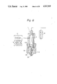
- FIG. 8 shows a sectional view of the fuel injection valve.
- These Figures show the system and constitution of an injector in which a needle is moved up and down by the expansion and contraction of the piezoelectric actuator, thus opening and closing a valve to control an amount and time of a fuel injection.
- the construction, operation, control method, and constant injection rate thereof are described in detail in Japanese Patent Application No. 60-81432 (TAKIGAWA et al. U.S. application Ser. No. 850,696 filed on Apr. 11, 1986).
- 1 denotes a fuel injection valve
- 2 a piezoelectric actuator
- 4 a control circuit
- 5 a Diesel engine 31 a high pressure pump
- 32 an accumulator.
- 504 denotes a piston, 510 a nozzle body, 511 a needle cylinder, 513 a nozzle needle, and 516 an injection nozzle.
- the drive circuit 100 in FIG. 5 is explained below.
- the battery 101 is the type normally used for an automobile, and a DC-DC converter 102 generates a high voltage from the voltage supplied thereto by the battery 101. This high voltage is stored in a capacitor 103.
- the DC-DC converter 102 is a well known step-up voltage type using a transformer.
- the anode of a thyristor 104 is connected to the capacitor 103 at the high voltage power side, and the cathode of the thyristor 104 is connected to a coil 105 having an inductance.
- the gate of the thyristor 104 is connected to a trigger generation circuit 150.
- the other terminal of the coil 105 is connected to the positive terminal of a piezoelectric actuator 2, and the negative terminal of the piezoelectric actuator 2 is grounded.
- the capacitor 103, the thyristor 104, the coil 105, and the piezoelectric actuator 2 form a series resonance circuit.
- the positive terminal of the piezoelectric actuator 2 is also connected to a coil 106 having an inductance.
- a coil 107 is wound with the coil 106 and these coils 106 and 107 are magnetically coupled to each other.
- the polarities of the coils 106 and 107 are reversed, as shown in FIG. 5.
- the other terminal of the coil 106 is connected to the collector of a transistor 109 through a diode 108, and thus the piezoelectric actuator 2, the coil 106, a diode 108, and the transistor 109 form a series resonance circuit.
- the diode 108 is provided to prevent the application of a negative voltage to the collector of the transistor 109.
- the emitter of the transistor 109 is grounded, and the base of the transistor 109 is connected to the trigger generation circuit 150 through resistances 110 and 111.
- One terminal of the coil 107 is grounded and the other is connected to the battery 101 through a diode 112 as the third switching element, which diode turns ON or OFF responding to the value and polarity of the applied voltage thereacross.
- the trigger generation circuit 150 is explained below. Input to the trigger generation circuit 150 are a main injection signal, a pilot injection signal, and a comparison signal V R , and these signals are supplied from an ECU 41, as described later.
- the main injection signal is applied to one input of a two input OR gate 151 and the pilot injection signal is applied to the other input of the OR gate 151.
- the logical sum of the main injection signal and the pilot injection signal is output from the OR gate 151, and this output is supplied to the falling edge trigger input of a monostable multivibrator 152, which is triggered at the falling edge of the input signal.
- the monostable multivibrator 152 outputs a pulse as Q, having pulse width which is determined by a capacitor 153 and a resistance 154, synchronized with the falling edge of the trigger signal.
- the output Q is the signal having a negative logic, and thus Q is brought to a logical "0" level during a determined time interval.
- the time interval is approximately 30 microseconds when this signal Q is used as a trigger signal for the thyristor 104.
- the output Q of the monostable multivibrator 152 is supplied to the base of a transistor 157 through a resistance 155.
- the transistor 157 is PNP type having an emitter directly connected to a power source and a base connected to the power source through a resistance 156.
- the collector of the transistor 157 is connected to a primary winding 159 of a pulse transformer 158.
- the transistor 157 is conductive, an electric current flows through the primary winding 159 of the pulse transformer 158, and a signal is generated across a secondary winding 160.
- This signal is supplied to the gate input of the thyristor 104 through a diode 161 and a resistance 162.
- a resistance 163 and a capacitor 164 are used to prevent the generation of noise.
- the above-mentioned main injection signal is supplied to the rising edge trigger input of a monostable multivibrator 165.
- the pulse width of the pulse output from the monostable multivibrator 165 is determined by a resistance 168 and a capacitor 167, and in this embodiment, is approximately 100 microseconds.
- the output Q of the monostable multivibrator 165 is supplied to one input of a two input OR gate 169, and the output of the two input OR gate 169 turns the transistor 109 ON or OFF through the resistances 110 and 111 as mentioned above.
- the data input D of a D flip-flop 170 is supplied at a "1" level and a set input S is connected to the ground level.
- the pilot injection signal is connected to a clock input C of the D flip-flop 170, and at the rising edge thereof, the data input level is latched and output.
- the output of a comparator 171 which will be mentioned later, is supplied to the reset input R of the D flip-flop 170, and the comparison voltage V R from the ECU 41 is supplied to the non-inversion (+) input of the comparator 171.
- a signal, the voltage of which is divided across the piezoelectric actuator 2 by 300 by using resistances 172 and 173, is supplied to the inversion (-) input of the comparator 171.
- FIG. 6 shows a constitution of the ECU 41, wherein an input interface 411 converts a voltage in response to an accelerator pedal opening rate supplied from an engine load sensor 53, and another voltage in response to a water temperature supplied from a temperature sensor 54, from analog to digital, and supplies the converted signals to a bus 415. Further the interface 411 counts the engine revolution number, from signals input by a reference sensor 52 and an angle sensor 51, and supplies the count to the bus 415. The data from the input interface 411 is input to a CPU (central processor unit) 412.
- a CPU central processor unit
- the CPU 412 operates the various data in response to commands from a ROM (read only memory) 413 in which a program is stored.
- a RAM (random access memory) 414 is used for the operation in the CPU 412.
- the data are sent and received between the circuits such as the input interface 411 and so on through the bus 415.
- an output interface 416 performs a predetermined counting operation, and outputs the main injection signal and the pilot injection signal at a predetermined timing.
- a digital-to-analog conversion (D/A) circuit 417 converts the comparison voltage data operated by the CPU 412 to an analog voltage V R .
- the coil 107 coupled with the coil 106 since the coil 107 coupled with the coil 106 is provided, the energy stored in the coil 106 is supplied to the battery 101 through the coil 107. Namely, the coil 107 is wound in reverse to the coil 106, and therefore, the electric current through the coil 106 is transformed at the coil 107, and flows into the battery 101 through the diode 112 (FIG. 9(K)). Accordingly, as the voltage applied to the coil 106 is product of the battery voltage and the winding ratio between the coils 106 and 107, the applied voltage can be suppressed within a predetermined voltage rating. Moreover, since energy can be returned to the battery as a regeneration power, compared with the diffusion of heat energy in the prior art, this energy regeneration provides a greater decrease in power consumption and heat generation.
- the monostable multivibrator 152 is triggered at the falling edge of the pilot injection signal, and then the thyristor 104 is triggered (FIG. 9(E)).
- the thyristor 104 is conductive and the high voltage stored in the capacitor 103 is applied to the piezoelectric actuator 2 through the thyristor 104 and the coil 105 (FIG. 9(F)).
- the piezoelectric actuator 2 is expanded, the injector valve is closed, and the injection is interrupted.
- the main injection signal is supplied and the monostable multivibrator 165 is triggered at the rising edge of this signal, and the transistor 109 becomes conductive during a predetermined interval (FIG. 9(D)).
- This interval is determined to be longer than a half of the series resonance period, which is effected by the piezoelectric actuator 2 and the coil 106. Since the transistor 109 is conductive and charge in the piezoelectric actuator 2 is discharged to a negative value, the piezoelectric actuator 2 is considerably contracted (FIG. 9(F)). As a result, the injector is fully open and a large injection is carried out (FIG. 9(L)). Then the monostable multivibrator 152 is triggered at the falling edge of the main injection signal, the thyristor 104 is made conductive, a high voltage is applied to the piezoelectric actuator 2, and the injection is completed.
- FIGS. 10A and 10B are a circuit diagram showing a partial constitution of a driving circuit for a piezoelectric actuator in a second embodiment of the invention.
- An example wherein the driving circuit is applied to an injector using a piezoelectric actuator is explained below.
- FIG. 12 and FIG. 13 are sectional views showing a system and a construction of a fuel injection valve which moves a piston 720 up and down by utilizing the expansion and contraction of the piezoelectric actuator 2, pressurizes fuel supplied to a pump chamber 703, and injects the fuel from a injection nozzle 712.
- the operating range of this fuel injection valve is limited narrower, and therefore, a conventional drive circuit 47 in FIG. 3 has been used to change the stroke of the piston and control the injected fuel amount but the drive circuit 47 in FIG. 3 has a complicated structure, a high cost, and a low efficiency because of power dissipation in a resistance 483 by the discharge of the stored charge in a capacitor 477.
- reference numerals 471 and 472 denote thyristors
- 43 denotes a trigger generation circuit
- 480 denotes an operational amplifier
- reference numerals 709 and 710 denote a nozzle body and a nozzle needle, respectively.
- a battery 201 generates a high voltage through a DC-DC converter 202, and the high voltage is stored in a capacitor 203.
- a coil 204 having an inductance is connected between the capacitor 203 and a positive terminal of a piezoelectric actuator 2.
- a coil 205 is wound and electromagnetically coupled with the coil 204. The polarities of the coils 204 and 205 are reversed, as shown in FIG. 10A.
- One terminal of the coil 205 is grounded and the other terminal is connected to the battery 201 through a thyristor 206.
- the gate of the thyristor 206 is connected to a trigger generation circuit 250, which will be explained later.
- the positive terminal of the piezoelectric actuator 2 is connected to the coil 204 as mentioned above, and the negative terminal thereof is connected to the collector of a transistor 208 through a diode 207.
- the emitter of the transistor 208 is grounded.
- the capacitor 203, the coil 204, the piezoelectric actuator 2, the diode 207, and the transistor 208 constitute a series resonance circuit.
- the base of the transistor 208 is connected to the trigger generation circuit 250 through resistances 209 and 210.
- the positive terminal of the piezoelectric actuator 2 is further connected to a coil 211.
- the anode of a thyristor 212 is connected to the coil 211 and the cathode thereof is connected to the negative terminal of the piezoelectric actuator 2.
- the piezoelectric actuator 2, the coil 211, and the thyristor 212 constitute a series resonance circuit.
- the gate of the thyristor 212 is connected to the trigger generation circuit 250.
- a drive signal and a comparison signal V R which are output from an ECU 41', which will be explained later, are sent to the trigger generation circuit 250.
- a capacitor 251 and a resistance 252 form a differential circuit and the circuit forms a pulse synchronized with a rising edge of the drive signal.
- This signal is supplied to a set terminal S of a flip-flop 253, to set the flip-flop 253. Namely, the output Q of the flip-flop 253 is "1" level.
- the reset terminal R of the flip-flop 253 is connected to the output of a comparator 254.
- the non-inversion (+) input of the comparator 254 receives a divided signal, which is divided the voltage across the piezoelectric actuator 2 by 300 using resistances 255 and 256.
- the inversion (-) input of the comparator receives the comparison signal V R .
- the output Q of the flip-flop 253 represents the trigger (TRIG) 1 signal and is connected to a base resistance 210 of the transistor 208. When the output Q is "1" level, the transistor 208 is conductive.
- the output Q of the flip-flop 253 is supplied to the falling edge trigger input of a monostable multivibrator 257, which trigger input receives a falling edge of an input pulse and operates the flip-flop 257.
- the output pulse width of the monostable multivibrator 257 is determined by a capacitor 258 and a resistance 259.
- the pulse width is approximately 30 microseconds, which is the time necessary to trigger the thyristor 206.
- the output Q of the monostable multivibrator 257 is supplied to the base of a transistor 262 through resistances 260 and 261.
- the emitter of the transistor 262 is connected to a power source, and the collector of the transistor 262 is connected to a primary winding 264 of a pulse transformer 263.
- the output Q of the monostable multivibrator 257 is "0" level, the transistor 262 is conductive, the electric current flows through the primary winding 264 of the pulse transformer 263, and a signal is generated across a secondary winding 265.
- This signal is the trigger (TRIG) 3 signal and is supplied to the gate input of the thyristor 206 through a diode 266 and a resistance 267.
- An output interface 416 is loaded with a digital value in response to a driving frequency operated by the CPU and a signal indicating that the driving frequency is formed.
- a monostable multivibrator 420 receives the signal from the output interface 416 and outputs a drive signal having a predetermined pulse width synchronized with the driving frequency signal. The pulse width is determined by the time constant of a capacitor 418 and a resistance 419, and in this case, is approximately 500 microseconds.
- a D/A conversion circuit 417 converts a digital signal corresponding to the comparison signal V R , which is operated by the CPU 412, to an analog voltage and outputs this voltage to the trigger generation circuit 250.
- the operation of the ECU 41' is now explained.
- the data of the driving frequency is output from the output interface 416 and triggers the monostable multivibrator 420, and the output of the monostable multivibrator 420 is the driving signal as shown in FIG. 14(A).
- the data of the comparison signal is output from the D/A conversion circuit 417 as the comparison signal V R (FIG. 14(B)).
- the drive signal applied to the trigger generation circuit 250 is differentiated through the capacitor 251 and the resistance 252 (FIG. 14(C)) and the flip-flop 253 is set at the rising edge thereof. Namely, the output Q of the flip-flop 253 is "1" level, and makes the transistor 208 conductive (FIG. 14(D)).
- the capacitor 203, the coil 204, the piezoelectric actuator 2, the diode 207, and the transistor 208 constitute a series resonance circuit. Then, the high voltage stored in the capacitor 203 is applied to the piezoelectric actuator 2 (FIG. 14(G)).
- the voltage at the negative terminal of the piezoelectric actuator 2 is the summation of the forward voltage drop of the diode 207 and the voltage drop between the collector and emitter of the transistor 208. This voltage is negligible. Therefore, the voltage of the positive terminal voltage of the piezoelectric actuator 2 divided by the resistances 255 and 256 corresponds to the voltage between the positive and the negative terminals of the piezoelectric actuator 2. The divided voltage is compared with the comparison signal V R through the comparator 254, and if the divided voltage is higher than that of the comparison signal V R , the output of the comparator 254 is "1" level (FIG. 14(H)) and the flip-flop 253 is reset.
- the output Q is "0" level and the transistor 208 is cut off (FIG. 14(D)).
- a considerable electric electric current has flowed through the coil 204 (FIG. 14(I)), and if the electric current is cut off abruptly, an abnormal high voltage is induced and the transistor 208 is destroyed.
- the coil 205 is coupled with the coil 204, and the energy stored in the coil 204 is returned to the power source through the coil 205.
- the monostable multivibrator 270 When the drive signal falls, the monostable multivibrator 270 is triggered, the transistor 275 is made conductive, and the thyristor 212 is triggered through the pulse transformer 276 (FIG. 14(E)).
- the thyristor 212 When the thyristor 212 is conductive, the piezoelectric actuator 2, the coil 211, and the thyristor 212 constitute a series resonance circuit. Then, the charges on the piezoelectric actuator 2 are decreased (FIG. 14(G)) and the piezoelectric actuator 2 is contracted.
- the voltage applied to the piezoelectric actuator 2 can be arbitrarily controlled by the comparison signal V R and with a reliable response characteristic.
- the voltage changes the amount of expansion or contraction of the piezoelectric actuator 2, and thus the quantity of fuel injected by the fuel injection valve in FIG. 13 can be controlled.
- the driving circuit of this embodiment has great advantages in that the power consumption is decreased and an apparatus using this circuit can be miniaturized and lighter in weight.
- the invention is not limited to this example. Namely, the invention can be utilized for controlling the load wherein the voltage applied to the capacitive-type load can be controlled with a reliable response characteristic and over a wide voltage range.
- FIG. 15 A modification of the second embodiment is shown in FIG. 15.
- the coils 204, 205, and 211 are wound on one core.
- the comparatively large size coils are made compact, and the apparatus using this modification can be miniaturized.
- the polarity of each coil is as shown in FIG. 15, the function is the same as that of the coils in FIGS. 10A and 10B.
- the energy returned from the coil 205 may be fed to the capacitor 203 storing the high voltage, as shown in FIG. 16, instead of to the battery 201. Accordingly, the energy restoration time can be reduced.
- FIGS. 17A and 17B A third embodiment is shown in FIGS. 17A and 17B.
- the cut off timing of the transistor 208 is controlled by the amount of charging, instead of by the terminal voltage, of the piezoelectric actuator.
- a resistance 401 is provided for detection of charge current, different from FIG. 10A.
- the voltage across the resistance 401 is integrated by a integration circuit comprising a resistance 291, an operational amplifier 292, and a capacitor 293.
- the integration value i.e., the charging amount, is compared with a comparison voltage V R at a comparator 254.
- a flip-flop 253 is reset and a transistor 208 is cut off.
- An analog switch 294 discharges the capacitor 293 for integration.
- the output Q of the flip-flop 253 is applied to the analog switch 294 through an inverter 295, and when the output Q is "0", i.e., the transistor 208 is OFF, the analog switch 294 turns ON and the capacitor 293 is initialized.
- the relationship between the expansion and contraction of the piezoelectric actuator and the amount of charge or discharge has a better linearity and no hysteresis characteristic, and therefore, the controllability and accuracy of the fuel injection quantity is increased.
- FIGS. 18A and 18B are a circuit diagram showing a structure of a driving circuit for a piezoelectric actuator according to the fourth embodiment.
- the circuit in FIGS. 18A and 18B combines the stroke control at discharge in the first embodiment and the stroke control at charge in the second embodiment. This embodiment has the merits of both the first and the second embodiments.
- the pump type injector in FIG. 13 pressurizes the fuel in the pump chamber 703 and injects the fuel from the injection nozzle 712.
- the piezoelectric actuator 2 operates with very quick motion, e.g., 100 microseconds for expansion
- the pump chamber 703 receives a shock pressure and an extremely large pressure pulsation is generated. Accordingly, problems arise wherein the pressure pulsation is felt in other portions or interacts in a complex manner, a secondary injection or higher degree injection occurs, and an adjustment accuracy of the fuel injection quantity is deteriorated.
- the driving circuit has an advantage in that it can arbitrarily control the apparent response speed by performing the charge and discharge of the piezoelectric actuator at a high speed and intermittently.
- a drive circuit 300 comprises a battery 301, a DC-DC converter 302, and a capacitor 303 storing the high voltage generated by the DC-DC converter 302.
- One terminal of a first coil 304 is connected to the capacitor 303, and the other terminal is connected to the positive terminal of the piezoelectric actuator 2.
- a diode 305 prevents a reverse flow of the electric current through a transistor 306.
- the collector of the PNP type transistor 306 is connected to the anode of a diode 305, and the emitter of the transistor 306 is grounded.
- the base of the transistor 306 is supplied with a trigger 1 signal from a trigger generation circuit 350 through resistances 307 and 308.
- the transistor 306, the diode 305, the capacitor 303, the first coil 304, and the piezoelectric actuator 2 constitute a series resonance circuit.
- a second coil 309 is wound on the core on which also the first coil is wound, and the polarities of the coil windings are as shown in FIG. 18A.
- One terminal of the second coil 309 is connected to the piezoelectric actuator 2 and the other terminal is connected to the anode of a diode 310.
- the collector of an NPN type transistor 311 is connected to the cathode of the diode 310 and the emitter of the transistor 311 is grounded.
- the diode 310 prevents a reverse flow of the electric current through the transistor 311.
- the base of the transistor 311 is connected to a trigger 2 signal from the trigger generation circuit 350 through resistances 312 and 313.
- a third coil 314 is wound on the same core on which the first coil 304 and the second coil 309 are wound.
- the polarity of the coil winding is as shown in FIG. 18A.
- One terminal of the third coil 314 is grounded and the other terminal of the third coil is connected to the anode of a thyristor 315.
- the cathode of the thyristor 315 is connected to the positive terminal of the battery 301, and the gate of the thyristor 315 is connected to a trigger 3 signal from the trigger generation circuit 350.
- the trigger generation circuit 350 is explained below.
- a rising signal and a falling signal are input to the trigger generation circuit 350 from an ECU 41", which will be later explained.
- the rising signal is supplied to an inverter 351 and the output of the inverter 351 is connected to the base of a transistor 354 through resistances 352 and 353.
- the collector of the transistor 354 is connected to the base of a transistor 357 through resistances 355 and 356.
- the emitter of the transistor 357 is connected, for example, to a -5 volt power source.
- the output from the collector of the transistor 357 is the trigger 1 signal and drives the transistor 308.
- the rising signal is further supplied to a two input OR gate 358, and the output of the two input OR gate 358 is supplied to the falling edge trigger input of a monostable multivibrator 359.
- the pulse width of the output of the monostable multivibrator 359 is determined by a capacitor 360 and a resistance 361. In this embodiment, the pulse width is approximately 30 microseconds, which is sufficient time to trigger the thyristor 315.
- the output Q of the monostable multivibrator 359 is connected to the base of a transistor 364 through resistances 362 and 363 and turns the same ON or OFF. Namely, the transistor 364 turns ON during 30 microseconds synchronously with the falling edge of the applied signal at the falling edge trigger input of the monostable multivibrator 359.
- the collector of the transistor 364 is connected to a primary winding 366 of a pulse transformer 365.
- the output from a secondary winding 367 of the pulse transformer 365 is the trigger 3 signal and is connected to the gate of the thyristor 315 through a diode 368 and a resistance 369.
- a resistance 370 and a capacitor 371 are used for noise prevention.
- the ECU 41" performs a predetermined operation and obtains a final driving frequency and a driving voltage.
- the explanation of this embodiment has been the same as that of the second embodiment.
- the ECU 41" outputs the rising signal having a pulse width, a pulse interval, and a pulse number in response to the driving voltage.
- the ECU 41" outputs the falling signal having a pulse width, a pulse interval, and a pulse number in response to the driving voltage.
- FIG. 19 is a time chart showing signal waveforms for explaining the operation of this embodiment.
- the trigger 1 signal is -5 volts (FIG. 19(C)) and turns ON the transistor 306.
- the transistor 306, the diode 305, the capacitor 303, the first coil 304, and the piezoelectric actuator 2 constitute a series resonance circuit, and the high voltage stored in the capacitor 303 is applied to the piezoelectric actuator 2.
- a sinusoidal oscillatory current flows. Since the rising signal is made to return to "0" level after a time shorter than that of a half period of the sinusoidal current, the electric current through the first coil 304 is abruptly turned OFF (FIG. 19(F)).
- the trigger 3 signal is generated from the monostable multivibrator 359 (FIG. 19(E)), and the thyristor 315 is made conductive. Since the first coil 304 is coupled to the third coil for power restoration, the stored energy in the first coil 304 is returned to the battery 301 (FIG. 19(H)) from the third coil 314 through the thyristor 315.
- the rising signal becomes "1" level again, the transistor 306 is made conductive, and the piezoelectric actuator 2 is again charged. Then, in the middle of the charging, the rising signal returns to "0" level, and the charging is interrupted. At that time, energy stored in the first coil 304 is returned to the battery 301. This return of energy is called restoration or regeneration. Subsequently, the restoration is repeated for a predetermined number of times, so that the charge of the piezoelectric actuator is performed gradually, and the charged voltage can rise slowly as shown in FIG. 19(I). Accordingly, the pressure in the pump chamber 703 in FIG. 13 rises comparatively slowly, the pulsation is suppressed, the secondary injection is eliminated, and the adjustment accuracy of the fuel injection quantity is increased.
- the operation regarding the falling signal is similar to that of the rising signal. That is, when the falling signal is "1" level (FIG. 19(B)), the transistor 311 is made conductive. Thus, the piezoelectric actuator 2, the second coil 309, the diode 310, and the transistor 311 constitute a series resonance circuit for charging. As a result, a sinusoidal oscillatory current flows in this resonant loop. On the other hand, since the falling signal is returned to the "0" level at the time shorter than a half period of the sinusoidal current, the electric current flowing through the second coil 309 is abruptly turned OFF (FIG. 19(G)).
- the third coil 314 is coupled to the second coil 309, and therefore, energy stored in the second coil 309 is returned to the battery 301 through the third coil 314 and the thyristor 315, which is conductive at the falling edge of the falling signal (FIG. 19(H)).
- the falling signal again becomes “1" level (FIG. 19(B))
- the transistor 311 is made conductive, and again, the piezoelectric actuator 2 is discharged. If in the middle of the discharge, the falling signal is "0", the discharge is interrupted. At that time, energy stored in the second coil 309 is also returned to the battery 301. Subsequently, after repetition for the predetermined number of times, the discharge of the piezoelectric actuator 2 is performed gradually and the voltage thereacross falls slowly as shown in FIG. 19(I). As a result, the pressure in the pump chamber 703 of FIG.
Landscapes
- Engineering & Computer Science (AREA)
- Chemical & Material Sciences (AREA)
- Combustion & Propulsion (AREA)
- Mechanical Engineering (AREA)
- General Engineering & Computer Science (AREA)
- Electrical Control Of Air Or Fuel Supplied To Internal-Combustion Engine (AREA)
- Fuel-Injection Apparatus (AREA)
- Apparatuses For Generation Of Mechanical Vibrations (AREA)
- Dc-Dc Converters (AREA)
Abstract
Description
Claims (15)
Applications Claiming Priority (2)
| Application Number | Priority Date | Filing Date | Title |
|---|---|---|---|
| JP61-217309 | 1986-09-17 | ||
| JP61217309A JPS6372381A (en) | 1986-09-17 | 1986-09-17 | Method of driving capacitive load |
Publications (1)
| Publication Number | Publication Date |
|---|---|
| US4767959A true US4767959A (en) | 1988-08-30 |
Family
ID=16702132
Family Applications (1)
| Application Number | Title | Priority Date | Filing Date |
|---|---|---|---|
| US07/094,738 Expired - Fee Related US4767959A (en) | 1986-09-17 | 1987-09-09 | Method and apparatus for driving capacitive-type load |
Country Status (2)
| Country | Link |
|---|---|
| US (1) | US4767959A (en) |
| JP (1) | JPS6372381A (en) |
Cited By (56)
| Publication number | Priority date | Publication date | Assignee | Title |
|---|---|---|---|---|
| US4947074A (en) * | 1986-11-15 | 1990-08-07 | Brother Kogyo Kabushiki Kaisha | Piezoelectric element drive circuit |
| US4945898A (en) * | 1989-07-12 | 1990-08-07 | Diasonics, Inc. | Power supply |
| US4966119A (en) * | 1988-01-12 | 1990-10-30 | Toyota Jidosha Kabushiki Kaisha | Fuel injection control device for use in an engine |
| EP0417771A1 (en) * | 1989-09-14 | 1991-03-20 | Hitachi Metals, Ltd. | High-voltage pulse generating circuit and electrostatic precipitator containing it |
| EP0427981A1 (en) * | 1988-10-25 | 1991-05-22 | GebràDer Sulzer Aktiengesellschaft | Electrohydraulic or pneumatic actuator |
| EP0431272A2 (en) * | 1989-11-03 | 1991-06-12 | MAN Nutzfahrzeuge Aktiengesellschaft | Method and device to inject fuel in the combustion chamber of an internal combustion engine |
| US5036263A (en) * | 1988-11-09 | 1991-07-30 | Nippondenso Co., Ltd. | Piezoelectric actuator driving apparatus |
| US5037217A (en) * | 1987-10-30 | 1991-08-06 | Brother Kogyo Kabushiki Kaisha | Dot-matrix impact printer using piezoelectric elements for activating print wires |
| US5053668A (en) * | 1989-01-18 | 1991-10-01 | Toyota Jidosha Kabushiki Kaisha | Apparatus for driving piezoelectric element for closing and opening valve member |
| EP0464443A1 (en) * | 1990-06-18 | 1992-01-08 | Toyota Jidosha Kabushiki Kaisha | Device for driving a piezoelectric element |
| US5095256A (en) * | 1988-11-29 | 1992-03-10 | Nec Corporation | Drive circuit for a piezoelectric actuator |
| GB2249891A (en) * | 1990-07-11 | 1992-05-20 | Brother Ind Ltd | Driving device for piezoelectric element |
| GB2250876A (en) * | 1990-10-09 | 1992-06-17 | Brother Ind Ltd | Driver circuit for piezoelectric element, having voltage limiter capable of charging the element with energy from coil after charging switch is off |
| US5126589A (en) * | 1990-08-31 | 1992-06-30 | Siemens Pacesetter, Inc. | Piezoelectric driver using resonant energy transfer |
| US5130598A (en) * | 1990-05-08 | 1992-07-14 | Caterpillar Inc. | Apparatus for driving a piezoelectric actuator |
| US5179311A (en) * | 1990-03-01 | 1993-01-12 | Nikon Corporation | Drive circuit for ultrasonic motors |
| US5208505A (en) * | 1990-06-08 | 1993-05-04 | Toyota Jidosha Kabushiki Kaisha | Device for driving a piezoelectric element |
| US5264752A (en) * | 1992-06-01 | 1993-11-23 | At&T Bell Laboratories | Amplifier for driving large capacitive loads |
| EP0611881A1 (en) * | 1993-01-19 | 1994-08-24 | Aisin Seiki Kabushiki Kaisha | Fuel injection control device for internal combustion engine |
| US5350962A (en) * | 1990-07-11 | 1994-09-27 | Brother Kogyo Kabushiki Kaisha | Driving device for piezoelectric element |
| US5361014A (en) * | 1993-11-10 | 1994-11-01 | Caterpillar Inc. | Apparatus for driving a piezoelectric actuator |
| US5361013A (en) * | 1992-02-06 | 1994-11-01 | Asulab S.A. | Device comprising a piezoelectric transducer |
| US5543679A (en) * | 1993-08-31 | 1996-08-06 | Nippondenso Co., Ltd. | Piezolectric-element drive apparatus |
| EP0728444A2 (en) * | 1989-08-18 | 1996-08-28 | Intertherapy, Inc. | Ultrasonic imaging system |
| WO1996031869A1 (en) * | 1995-04-05 | 1996-10-10 | Societe De Composants Electriques | Piezoelectric horn, particularly for vehicles |
| US5744988A (en) * | 1995-09-29 | 1998-04-28 | Condon; Joseph Henry | Amplifier circuits for driving large capacitive loads |
| US5895998A (en) * | 1997-09-18 | 1999-04-20 | Raytheon Company | Piezoelectric drive circuit |
| US6043570A (en) * | 1998-02-17 | 2000-03-28 | Matsushita Electronics Corporation | Driving circuit for capacitive load |
| US6111335A (en) * | 1993-12-28 | 2000-08-29 | Beniamin Acatrinei | Piezoelectric interface analyzer |
| US6118205A (en) * | 1998-08-13 | 2000-09-12 | Electronics For Imaging, Inc. | Transducer signal waveshaping system |
| US6121715A (en) * | 1996-12-18 | 2000-09-19 | Siemens Aktiengesellschaft | Method and device for driving a capacitive control element |
| US6147433A (en) * | 1997-08-02 | 2000-11-14 | Robert Bosch Gmbh | Method and device for charging and discharging a piezoelectric element |
| US6155500A (en) * | 1998-07-01 | 2000-12-05 | Isuzu Motors Limited | Piezoelectric actuator and fuel-injection apparatus using the actuator |
| US6194812B1 (en) * | 1996-09-30 | 2001-02-27 | Siemens Aktiengesellschaft | Controller with an actuator of controllable length and device for transmitting the deflection of an actuator |
| US6271618B1 (en) * | 1998-09-30 | 2001-08-07 | Siemens Aktiengesellschaft | Method and configuration for driving a capacitive actuator |
| US6333585B1 (en) * | 1998-09-23 | 2001-12-25 | Siemens Aktiengesellschaft | Discharge circuit for a capacitive actuator |
| WO2002001651A1 (en) * | 2000-06-23 | 2002-01-03 | Shanks Wayne E | High-efficiency regenerative piezoelectric drive amplifier |
| WO2002025747A2 (en) * | 2000-09-19 | 2002-03-28 | Stmicroelectronics S.R.L. | Electronic circuit for highly efficient driving of piezoelectric loads |
| US6366063B1 (en) * | 2000-03-22 | 2002-04-02 | Nec Corporation | Circuit and method for driving capacitive load |
| US6411009B2 (en) * | 1999-12-17 | 2002-06-25 | Eads Deutschland Gmbh | Piezoelectric actuator system |
| EP1217667A2 (en) * | 2000-12-22 | 2002-06-26 | Denso Corporation | Driving apparatus for piezo-actuator having abnormality detecting function |
| US6472796B1 (en) * | 1998-06-25 | 2002-10-29 | Siemens Aktiengesellschaft | Method and apparatus for controlling a capacitive actuator |
| US6486587B2 (en) * | 1999-01-29 | 2002-11-26 | Daimlerchrysler Ag | Device for controlling a piezoelement injection valve |
| US6566790B1 (en) * | 1999-09-13 | 2003-05-20 | Minolta Co., Ltd. | Driving apparatus and driving method of piezoelectric actuator |
| US20030099071A1 (en) * | 2001-10-20 | 2003-05-29 | Joerg Reineke | Circuit system for discharging a buffer capacitor used for supplying high voltage to a control unit, in particular a control unit for actuating a piezoelectric output stage |
| US6637677B1 (en) * | 1999-06-01 | 2003-10-28 | Robert Bosch Gmbh | Fuel injector |
| US6680620B2 (en) * | 2000-04-01 | 2004-01-20 | Robert Bosch Gmbh | Method for timed measurements of the voltage across a device in the charging circuit of a piezoelectric element |
| EP1398489A1 (en) * | 2002-09-13 | 2004-03-17 | Renault s.a.s. | Control method and apparatus for a piezoelectric injector |
| WO2004036662A2 (en) * | 2002-10-16 | 2004-04-29 | Volkswagen Mechatronic Gmbh & Co. Kg | Circuit with at least one piezoelectric actuator |
| US20050057119A1 (en) * | 2003-07-15 | 2005-03-17 | Paolo Reggio | Voltage booster circuit for powering a piezoelectric actuator of an injector |
| US20070114881A1 (en) * | 2005-11-18 | 2007-05-24 | Jensen Eric L | Actuator with amplified stroke length |
| US20090159052A1 (en) * | 2006-05-24 | 2009-06-25 | Herbert Steinbauer | Apparatus for Actuating at Least One Piezoelectric Actuating Drive of an Injection Nozzle for an Internal Combustion Engine |
| US20090184176A1 (en) * | 2008-01-22 | 2009-07-23 | Michael Peter Cooke | Fuel injector and operating method therefor |
| US20100131175A1 (en) * | 2007-03-27 | 2010-05-27 | Christian Kuhnert | Fuel injection system and method for injecting fuel |
| US20100140291A1 (en) * | 2007-03-19 | 2010-06-10 | The Technology Partnership Plc | Droplet spray generation device |
| US20120065869A1 (en) * | 2010-09-14 | 2012-03-15 | Hyundai Motor Company | System and Method for Controlling the Number of Pilot Injections |
Families Citing this family (4)
| Publication number | Priority date | Publication date | Assignee | Title |
|---|---|---|---|---|
| JP3209337B2 (en) * | 1989-10-23 | 2001-09-17 | 東北特殊鋼株式会社 | Solenoid valve drive circuit |
| JP3885283B2 (en) * | 1997-05-09 | 2007-02-21 | 日産自動車株式会社 | Drive device for fuel injection valve |
| US7856964B2 (en) * | 2006-05-23 | 2010-12-28 | Delphi Technologies Holding S.Arl | Method of controlling a piezoelectric actuator |
| GB2494116B (en) * | 2011-08-26 | 2013-08-07 | Global Inkjet Systems Ltd | Method of driving a capacitive load and drive circuit therefor |
Citations (8)
| Publication number | Priority date | Publication date | Assignee | Title |
|---|---|---|---|---|
| US3800170A (en) * | 1973-03-16 | 1974-03-26 | Ibm | Low power dissipation high voltage crystal driver |
| US4126867A (en) * | 1977-08-29 | 1978-11-21 | Silonics, Inc. | Ink jet printer driving circuit |
| JPS5864077A (en) * | 1981-10-14 | 1983-04-16 | Oki Electric Ind Co Ltd | Electrostrictive element driving circuit |
| US4398204A (en) * | 1980-09-30 | 1983-08-09 | Siemens Aktiengesellschaft | Circuit for operating recording nozzles |
| US4570098A (en) * | 1983-06-20 | 1986-02-11 | Nippon Soken, Inc. | Temperature compensated stack of piezoelectric elements |
| US4593658A (en) * | 1984-05-01 | 1986-06-10 | Moloney Paul J | Valve operating mechanism for internal combustion and like-valved engines |
| US4644212A (en) * | 1984-05-11 | 1987-02-17 | Nippon Soken, Inc. | Power supply for piezoelectric-element driving device |
| US4705003A (en) * | 1984-10-17 | 1987-11-10 | Nippon Soken, Inc. | Apparatus for controlling electroexpansive actuator avoiding deterioration of polarization |
-
1986
- 1986-09-17 JP JP61217309A patent/JPS6372381A/en active Pending
-
1987
- 1987-09-09 US US07/094,738 patent/US4767959A/en not_active Expired - Fee Related
Patent Citations (8)
| Publication number | Priority date | Publication date | Assignee | Title |
|---|---|---|---|---|
| US3800170A (en) * | 1973-03-16 | 1974-03-26 | Ibm | Low power dissipation high voltage crystal driver |
| US4126867A (en) * | 1977-08-29 | 1978-11-21 | Silonics, Inc. | Ink jet printer driving circuit |
| US4398204A (en) * | 1980-09-30 | 1983-08-09 | Siemens Aktiengesellschaft | Circuit for operating recording nozzles |
| JPS5864077A (en) * | 1981-10-14 | 1983-04-16 | Oki Electric Ind Co Ltd | Electrostrictive element driving circuit |
| US4570098A (en) * | 1983-06-20 | 1986-02-11 | Nippon Soken, Inc. | Temperature compensated stack of piezoelectric elements |
| US4593658A (en) * | 1984-05-01 | 1986-06-10 | Moloney Paul J | Valve operating mechanism for internal combustion and like-valved engines |
| US4644212A (en) * | 1984-05-11 | 1987-02-17 | Nippon Soken, Inc. | Power supply for piezoelectric-element driving device |
| US4705003A (en) * | 1984-10-17 | 1987-11-10 | Nippon Soken, Inc. | Apparatus for controlling electroexpansive actuator avoiding deterioration of polarization |
Cited By (85)
| Publication number | Priority date | Publication date | Assignee | Title |
|---|---|---|---|---|
| US4947074A (en) * | 1986-11-15 | 1990-08-07 | Brother Kogyo Kabushiki Kaisha | Piezoelectric element drive circuit |
| US5037217A (en) * | 1987-10-30 | 1991-08-06 | Brother Kogyo Kabushiki Kaisha | Dot-matrix impact printer using piezoelectric elements for activating print wires |
| US4966119A (en) * | 1988-01-12 | 1990-10-30 | Toyota Jidosha Kabushiki Kaisha | Fuel injection control device for use in an engine |
| EP0427981A1 (en) * | 1988-10-25 | 1991-05-22 | GebràDer Sulzer Aktiengesellschaft | Electrohydraulic or pneumatic actuator |
| US5036263A (en) * | 1988-11-09 | 1991-07-30 | Nippondenso Co., Ltd. | Piezoelectric actuator driving apparatus |
| US5095256A (en) * | 1988-11-29 | 1992-03-10 | Nec Corporation | Drive circuit for a piezoelectric actuator |
| US5053668A (en) * | 1989-01-18 | 1991-10-01 | Toyota Jidosha Kabushiki Kaisha | Apparatus for driving piezoelectric element for closing and opening valve member |
| US4945898A (en) * | 1989-07-12 | 1990-08-07 | Diasonics, Inc. | Power supply |
| EP0728444A2 (en) * | 1989-08-18 | 1996-08-28 | Intertherapy, Inc. | Ultrasonic imaging system |
| EP1312310A3 (en) * | 1989-08-18 | 2003-07-02 | Boston Scientific Limited | Ultrasonic imaging system |
| EP0728444A3 (en) * | 1989-08-18 | 1998-01-07 | Intertherapy, Inc. | Ultrasonic imaging system |
| EP0417771A1 (en) * | 1989-09-14 | 1991-03-20 | Hitachi Metals, Ltd. | High-voltage pulse generating circuit and electrostatic precipitator containing it |
| US5623171A (en) * | 1989-09-14 | 1997-04-22 | Hitachi Metals, Ltd. | High-voltage pulse generating circuit and electrostatic recipitator containing it |
| EP0431272A2 (en) * | 1989-11-03 | 1991-06-12 | MAN Nutzfahrzeuge Aktiengesellschaft | Method and device to inject fuel in the combustion chamber of an internal combustion engine |
| EP0431272A3 (en) * | 1989-11-03 | 1991-10-16 | Man Nutzfahrzeuge Aktiengesellschaft | Method and device to inject fuel in the combustion chamber of an internal combustion engine |
| US5179311A (en) * | 1990-03-01 | 1993-01-12 | Nikon Corporation | Drive circuit for ultrasonic motors |
| US5130598A (en) * | 1990-05-08 | 1992-07-14 | Caterpillar Inc. | Apparatus for driving a piezoelectric actuator |
| US5208505A (en) * | 1990-06-08 | 1993-05-04 | Toyota Jidosha Kabushiki Kaisha | Device for driving a piezoelectric element |
| US5204576A (en) * | 1990-06-18 | 1993-04-20 | Toyota Jidosha Kabushiki Kaisha | Device for driving a piezoelectric element |
| EP0464443A1 (en) * | 1990-06-18 | 1992-01-08 | Toyota Jidosha Kabushiki Kaisha | Device for driving a piezoelectric element |
| GB2249891A (en) * | 1990-07-11 | 1992-05-20 | Brother Ind Ltd | Driving device for piezoelectric element |
| GB2249891B (en) * | 1990-07-11 | 1994-04-27 | Brother Ind Ltd | Driving device for piezoelectric element |
| US5350962A (en) * | 1990-07-11 | 1994-09-27 | Brother Kogyo Kabushiki Kaisha | Driving device for piezoelectric element |
| US5126589A (en) * | 1990-08-31 | 1992-06-30 | Siemens Pacesetter, Inc. | Piezoelectric driver using resonant energy transfer |
| GB2250876A (en) * | 1990-10-09 | 1992-06-17 | Brother Ind Ltd | Driver circuit for piezoelectric element, having voltage limiter capable of charging the element with energy from coil after charging switch is off |
| GB2250876B (en) * | 1990-10-09 | 1995-04-19 | Brother Ind Ltd | Driver circuit for piezoelectric element having voltage limiter capable of charging the element with energy from coil after charging switch is off |
| US5214340A (en) * | 1990-10-09 | 1993-05-25 | Brother Kogyo Kabushiki Kaisha | Driver circuit for piezoelectric element, having voltage limiter capable of charging the element with energy from coil after charging switch is off |
| US5361013A (en) * | 1992-02-06 | 1994-11-01 | Asulab S.A. | Device comprising a piezoelectric transducer |
| US5264752A (en) * | 1992-06-01 | 1993-11-23 | At&T Bell Laboratories | Amplifier for driving large capacitive loads |
| US5425343A (en) * | 1993-01-19 | 1995-06-20 | Aisin Seiki Kabushiki Kaisha | Fuel injection control device for internal combustion engine |
| EP0611881A1 (en) * | 1993-01-19 | 1994-08-24 | Aisin Seiki Kabushiki Kaisha | Fuel injection control device for internal combustion engine |
| US5543679A (en) * | 1993-08-31 | 1996-08-06 | Nippondenso Co., Ltd. | Piezolectric-element drive apparatus |
| US5361014A (en) * | 1993-11-10 | 1994-11-01 | Caterpillar Inc. | Apparatus for driving a piezoelectric actuator |
| US6111335A (en) * | 1993-12-28 | 2000-08-29 | Beniamin Acatrinei | Piezoelectric interface analyzer |
| FR2732805A1 (en) * | 1995-04-05 | 1996-10-11 | Klaxon Sa | PIEZOELECTRIC SOUND WARNING DEVICE, PARTICULARLY FOR VEHICLE EQUIPMENT |
| US6166624A (en) * | 1995-04-05 | 2000-12-26 | Societe De Composants Electriques | Piezoelectric horn, particularly for vehicles |
| WO1996031869A1 (en) * | 1995-04-05 | 1996-10-10 | Societe De Composants Electriques | Piezoelectric horn, particularly for vehicles |
| US5744988A (en) * | 1995-09-29 | 1998-04-28 | Condon; Joseph Henry | Amplifier circuits for driving large capacitive loads |
| US6194812B1 (en) * | 1996-09-30 | 2001-02-27 | Siemens Aktiengesellschaft | Controller with an actuator of controllable length and device for transmitting the deflection of an actuator |
| US6121715A (en) * | 1996-12-18 | 2000-09-19 | Siemens Aktiengesellschaft | Method and device for driving a capacitive control element |
| US6147433A (en) * | 1997-08-02 | 2000-11-14 | Robert Bosch Gmbh | Method and device for charging and discharging a piezoelectric element |
| US5895998A (en) * | 1997-09-18 | 1999-04-20 | Raytheon Company | Piezoelectric drive circuit |
| US6043570A (en) * | 1998-02-17 | 2000-03-28 | Matsushita Electronics Corporation | Driving circuit for capacitive load |
| US6472796B1 (en) * | 1998-06-25 | 2002-10-29 | Siemens Aktiengesellschaft | Method and apparatus for controlling a capacitive actuator |
| US6155500A (en) * | 1998-07-01 | 2000-12-05 | Isuzu Motors Limited | Piezoelectric actuator and fuel-injection apparatus using the actuator |
| US6118205A (en) * | 1998-08-13 | 2000-09-12 | Electronics For Imaging, Inc. | Transducer signal waveshaping system |
| US6333585B1 (en) * | 1998-09-23 | 2001-12-25 | Siemens Aktiengesellschaft | Discharge circuit for a capacitive actuator |
| US6271618B1 (en) * | 1998-09-30 | 2001-08-07 | Siemens Aktiengesellschaft | Method and configuration for driving a capacitive actuator |
| US6486587B2 (en) * | 1999-01-29 | 2002-11-26 | Daimlerchrysler Ag | Device for controlling a piezoelement injection valve |
| US6637677B1 (en) * | 1999-06-01 | 2003-10-28 | Robert Bosch Gmbh | Fuel injector |
| US6566790B1 (en) * | 1999-09-13 | 2003-05-20 | Minolta Co., Ltd. | Driving apparatus and driving method of piezoelectric actuator |
| US6411009B2 (en) * | 1999-12-17 | 2002-06-25 | Eads Deutschland Gmbh | Piezoelectric actuator system |
| US6366063B1 (en) * | 2000-03-22 | 2002-04-02 | Nec Corporation | Circuit and method for driving capacitive load |
| US6680620B2 (en) * | 2000-04-01 | 2004-01-20 | Robert Bosch Gmbh | Method for timed measurements of the voltage across a device in the charging circuit of a piezoelectric element |
| WO2002001651A1 (en) * | 2000-06-23 | 2002-01-03 | Shanks Wayne E | High-efficiency regenerative piezoelectric drive amplifier |
| US20020136418A1 (en) * | 2000-06-23 | 2002-09-26 | Zavis Wayne M. | High efficiency regenerative piezoelectric drive amplifier |
| US20030062802A1 (en) * | 2000-09-19 | 2003-04-03 | Stmicroelectronics S.R.L. | Electronic circuit for highly efficient driving of piezoelectric loads |
| US20060261704A1 (en) * | 2000-09-19 | 2006-11-23 | Stmicroelectronics S.R.I. | Electronic circuit for highly efficient driving of piezoelectric loads |
| WO2002025747A2 (en) * | 2000-09-19 | 2002-03-28 | Stmicroelectronics S.R.L. | Electronic circuit for highly efficient driving of piezoelectric loads |
| WO2002025747A3 (en) * | 2000-09-19 | 2002-06-13 | St Microelectronics Srl | Electronic circuit for highly efficient driving of piezoelectric loads |
| US8154172B2 (en) | 2000-09-19 | 2012-04-10 | Stmicroelectronics S.R.L. | Electronic circuit for highly efficient driving of piezoelectric loads |
| US7061157B2 (en) * | 2000-09-19 | 2006-06-13 | Stmicroelectronics S.R.L. | Electronic circuit for highly efficient driving of piezoelectric loads |
| EP1217667A2 (en) * | 2000-12-22 | 2002-06-26 | Denso Corporation | Driving apparatus for piezo-actuator having abnormality detecting function |
| EP1217667A3 (en) * | 2000-12-22 | 2005-04-06 | Denso Corporation | Driving apparatus for piezo-actuator having abnormality detecting function |
| US20030099071A1 (en) * | 2001-10-20 | 2003-05-29 | Joerg Reineke | Circuit system for discharging a buffer capacitor used for supplying high voltage to a control unit, in particular a control unit for actuating a piezoelectric output stage |
| US6982517B2 (en) * | 2001-10-20 | 2006-01-03 | Robert Bosch Gmbh | Circuit system for discharging a buffer capacitor used for supplying high voltage to a control unit, in particular a control unit for actuating a piezoelectric output stage |
| EP1398489A1 (en) * | 2002-09-13 | 2004-03-17 | Renault s.a.s. | Control method and apparatus for a piezoelectric injector |
| WO2004036662A3 (en) * | 2002-10-16 | 2004-09-10 | Volkswagen Mechatronic Gmbh | Circuit with at least one piezoelectric actuator |
| US7271521B2 (en) | 2002-10-16 | 2007-09-18 | Volkswagen Mechatronic Gmbh & Co. Kg | Circuit having at least one piezoelectric actuator |
| WO2004036662A2 (en) * | 2002-10-16 | 2004-04-29 | Volkswagen Mechatronic Gmbh & Co. Kg | Circuit with at least one piezoelectric actuator |
| US20050235966A1 (en) * | 2002-10-16 | 2005-10-27 | Heinz Lixl | Circuit having at least one piezoelectric actuator |
| US20050057119A1 (en) * | 2003-07-15 | 2005-03-17 | Paolo Reggio | Voltage booster circuit for powering a piezoelectric actuator of an injector |
| US7199502B2 (en) * | 2003-07-15 | 2007-04-03 | C.R.F. SOCIETá CONSORTILE PER AZIONI | Voltage booster circuit for powering a piezoelectric actuator of an injector |
| US20070114881A1 (en) * | 2005-11-18 | 2007-05-24 | Jensen Eric L | Actuator with amplified stroke length |
| US7307371B2 (en) * | 2005-11-18 | 2007-12-11 | Delphi Technologies, Inc. | Actuator with amplified stroke length |
| US7765987B2 (en) * | 2006-05-24 | 2010-08-03 | Steinbauer Electronics Development Gmbh | Apparatus for actuating at least one piezoelectric actuating drive of an injection nozzle for an internal combustion engine |
| US20090159052A1 (en) * | 2006-05-24 | 2009-06-25 | Herbert Steinbauer | Apparatus for Actuating at Least One Piezoelectric Actuating Drive of an Injection Nozzle for an Internal Combustion Engine |
| US7977849B2 (en) * | 2007-03-19 | 2011-07-12 | The Technology Partnership Plc | Droplet spray generation device |
| US20100140291A1 (en) * | 2007-03-19 | 2010-06-10 | The Technology Partnership Plc | Droplet spray generation device |
| US20100131175A1 (en) * | 2007-03-27 | 2010-05-27 | Christian Kuhnert | Fuel injection system and method for injecting fuel |
| US8099225B2 (en) * | 2007-03-27 | 2012-01-17 | Robert Bosch Gmbh | Fuel injection system and method for injecting fuel |
| US20090184176A1 (en) * | 2008-01-22 | 2009-07-23 | Michael Peter Cooke | Fuel injector and operating method therefor |
| US8544764B2 (en) * | 2008-01-22 | 2013-10-01 | Delphi Technologies Holding S.Arl | Fuel injector and operating method therefor |
| US20120065869A1 (en) * | 2010-09-14 | 2012-03-15 | Hyundai Motor Company | System and Method for Controlling the Number of Pilot Injections |
| US9091225B2 (en) * | 2010-09-14 | 2015-07-28 | Hyundai Motor Company | System and method for controlling the number of pilot injections |
Also Published As
| Publication number | Publication date |
|---|---|
| JPS6372381A (en) | 1988-04-02 |
Similar Documents
| Publication | Publication Date | Title |
|---|---|---|
| US4767959A (en) | Method and apparatus for driving capacitive-type load | |
| US5130598A (en) | Apparatus for driving a piezoelectric actuator | |
| US6016040A (en) | Device and method for driving at least one capacitive actuator | |
| US6407593B1 (en) | Electromagnetic load control apparatus having variable drive-starting energy supply | |
| US6760212B2 (en) | Piezoelectric injector drive circuit | |
| US6157174A (en) | Method and device for driving a capacitive control element | |
| JP2002371895A (en) | Drive control device for injector | |
| US8149559B2 (en) | Piezoelectric actuator driving device and method | |
| US5361014A (en) | Apparatus for driving a piezoelectric actuator | |
| US6577488B1 (en) | Inductive load driver utilizing energy recovery | |
| US6081062A (en) | Method and device for driving at least one capacitive actuator | |
| JP2005504499A (en) | Converter circuit | |
| US4438751A (en) | High voltage generating circuit for an automotive ignition system | |
| JP2684650B2 (en) | Piezo element drive | |
| JP3765286B2 (en) | Piezo actuator drive circuit | |
| JP3222012B2 (en) | Solenoid valve drive circuit | |
| JPH02103970A (en) | Driving circuit for piezoelectric element | |
| JP2004320869A (en) | Piezoelectric actuator drive circuit | |
| JPS6397854A (en) | Piezo-actuator drive circuit | |
| JP3036105B2 (en) | Drive circuit for piezo actuator | |
| US20040208042A1 (en) | Power output stage for capacitive loads | |
| JP4465933B2 (en) | Electromagnetic actuator drive device | |
| JP2001012285A (en) | Electromagnetic load driving gear | |
| JP2853119B2 (en) | Piezo actuator drive circuit | |
| JP2773585B2 (en) | Piezo element drive circuit |
Legal Events
| Date | Code | Title | Description |
|---|---|---|---|
| AS | Assignment |
Owner name: NIPPONDENSO CO., LTD., 1-1, SHOWA-CHO, KARIYA-SHI, Free format text: ASSIGNMENT OF ASSIGNORS INTEREST.;ASSIGNORS:SAKAKIBARA, YASUYUKI;IGASHIRA, TOSHIHIKO;SEKIGUCHI, KIYONORI;AND OTHERS;REEL/FRAME:004770/0559 Effective date: 19870825 Owner name: NIPPON SOKEN, INC., 14, IWAYA, SHIMOHASUMI-CHO, NI Free format text: ASSIGNMENT OF ASSIGNORS INTEREST.;ASSIGNORS:SAKAKIBARA, YASUYUKI;IGASHIRA, TOSHIHIKO;SEKIGUCHI, KIYONORI;AND OTHERS;REEL/FRAME:004770/0559 Effective date: 19870825 Owner name: NIPPONDENSO CO., LTD.,JAPAN Free format text: ASSIGNMENT OF ASSIGNORS INTEREST;ASSIGNORS:SAKAKIBARA, YASUYUKI;IGASHIRA, TOSHIHIKO;SEKIGUCHI, KIYONORI;AND OTHERS;REEL/FRAME:004770/0559 Effective date: 19870825 Owner name: NIPPON SOKEN, INC.,JAPAN Free format text: ASSIGNMENT OF ASSIGNORS INTEREST;ASSIGNORS:SAKAKIBARA, YASUYUKI;IGASHIRA, TOSHIHIKO;SEKIGUCHI, KIYONORI;AND OTHERS;REEL/FRAME:004770/0559 Effective date: 19870825 |
|
| FEPP | Fee payment procedure |
Free format text: PAYER NUMBER DE-ASSIGNED (ORIGINAL EVENT CODE: RMPN); ENTITY STATUS OF PATENT OWNER: LARGE ENTITY Free format text: PAYOR NUMBER ASSIGNED (ORIGINAL EVENT CODE: ASPN); ENTITY STATUS OF PATENT OWNER: LARGE ENTITY |
|
| FPAY | Fee payment |
Year of fee payment: 4 |
|
| FPAY | Fee payment |
Year of fee payment: 8 |
|
| REMI | Maintenance fee reminder mailed | ||
| LAPS | Lapse for failure to pay maintenance fees | ||
| FP | Lapsed due to failure to pay maintenance fee |
Effective date: 20000830 |
|
| STCH | Information on status: patent discontinuation |
Free format text: PATENT EXPIRED DUE TO NONPAYMENT OF MAINTENANCE FEES UNDER 37 CFR 1.362 |