US3815863A - Collapsible flexible material candle mold - Google Patents
Collapsible flexible material candle mold Download PDFInfo
- Publication number
- US3815863A US3815863A US00262245A US26224572A US3815863A US 3815863 A US3815863 A US 3815863A US 00262245 A US00262245 A US 00262245A US 26224572 A US26224572 A US 26224572A US 3815863 A US3815863 A US 3815863A
- Authority
- US
- United States
- Prior art keywords
- mold
- bladder
- inflatable
- candle
- fluid pressure
- Prior art date
- Legal status (The legal status is an assumption and is not a legal conclusion. Google has not performed a legal analysis and makes no representation as to the accuracy of the status listed.)
- Expired - Lifetime
Links
Images
Classifications
-
- C—CHEMISTRY; METALLURGY
- C11—ANIMAL OR VEGETABLE OILS, FATS, FATTY SUBSTANCES OR WAXES; FATTY ACIDS THEREFROM; DETERGENTS; CANDLES
- C11C—FATTY ACIDS FROM FATS, OILS OR WAXES; CANDLES; FATS, OILS OR FATTY ACIDS BY CHEMICAL MODIFICATION OF FATS, OILS, OR FATTY ACIDS OBTAINED THEREFROM
- C11C5/00—Candles
- C11C5/02—Apparatus for preparation thereof
-
- B—PERFORMING OPERATIONS; TRANSPORTING
- B29—WORKING OF PLASTICS; WORKING OF SUBSTANCES IN A PLASTIC STATE IN GENERAL
- B29C—SHAPING OR JOINING OF PLASTICS; SHAPING OF MATERIAL IN A PLASTIC STATE, NOT OTHERWISE PROVIDED FOR; AFTER-TREATMENT OF THE SHAPED PRODUCTS, e.g. REPAIRING
- B29C33/00—Moulds or cores; Details thereof or accessories therefor
- B29C33/44—Moulds or cores; Details thereof or accessories therefor with means for, or specially constructed to facilitate, the removal of articles, e.g. of undercut articles
- B29C33/48—Moulds or cores; Details thereof or accessories therefor with means for, or specially constructed to facilitate, the removal of articles, e.g. of undercut articles with means for collapsing or disassembling
- B29C33/50—Moulds or cores; Details thereof or accessories therefor with means for, or specially constructed to facilitate, the removal of articles, e.g. of undercut articles with means for collapsing or disassembling elastic or flexible
- B29C33/505—Moulds or cores; Details thereof or accessories therefor with means for, or specially constructed to facilitate, the removal of articles, e.g. of undercut articles with means for collapsing or disassembling elastic or flexible cores or mandrels, e.g. inflatable
-
- B—PERFORMING OPERATIONS; TRANSPORTING
- B29—WORKING OF PLASTICS; WORKING OF SUBSTANCES IN A PLASTIC STATE IN GENERAL
- B29C—SHAPING OR JOINING OF PLASTICS; SHAPING OF MATERIAL IN A PLASTIC STATE, NOT OTHERWISE PROVIDED FOR; AFTER-TREATMENT OF THE SHAPED PRODUCTS, e.g. REPAIRING
- B29C67/00—Shaping techniques not covered by groups B29C39/00 - B29C65/00, B29C70/00 or B29C73/00
- B29C67/24—Shaping techniques not covered by groups B29C39/00 - B29C65/00, B29C70/00 or B29C73/00 characterised by the choice of material
- B29C67/241—Moulding wax
-
- B—PERFORMING OPERATIONS; TRANSPORTING
- B29—WORKING OF PLASTICS; WORKING OF SUBSTANCES IN A PLASTIC STATE IN GENERAL
- B29C—SHAPING OR JOINING OF PLASTICS; SHAPING OF MATERIAL IN A PLASTIC STATE, NOT OTHERWISE PROVIDED FOR; AFTER-TREATMENT OF THE SHAPED PRODUCTS, e.g. REPAIRING
- B29C39/00—Shaping by casting, i.e. introducing the moulding material into a mould or between confining surfaces without significant moulding pressure; Apparatus therefor
-
- B—PERFORMING OPERATIONS; TRANSPORTING
- B29—WORKING OF PLASTICS; WORKING OF SUBSTANCES IN A PLASTIC STATE IN GENERAL
- B29L—INDEXING SCHEME ASSOCIATED WITH SUBCLASS B29C, RELATING TO PARTICULAR ARTICLES
- B29L2031/00—Other particular articles
- B29L2031/747—Lightning equipment
- B29L2031/7472—Lampshades
-
- Y—GENERAL TAGGING OF NEW TECHNOLOGICAL DEVELOPMENTS; GENERAL TAGGING OF CROSS-SECTIONAL TECHNOLOGIES SPANNING OVER SEVERAL SECTIONS OF THE IPC; TECHNICAL SUBJECTS COVERED BY FORMER USPC CROSS-REFERENCE ART COLLECTIONS [XRACs] AND DIGESTS
- Y10—TECHNICAL SUBJECTS COVERED BY FORMER USPC
- Y10S—TECHNICAL SUBJECTS COVERED BY FORMER USPC CROSS-REFERENCE ART COLLECTIONS [XRACs] AND DIGESTS
- Y10S425/00—Plastic article or earthenware shaping or treating: apparatus
- Y10S425/044—Rubber mold
-
- Y—GENERAL TAGGING OF NEW TECHNOLOGICAL DEVELOPMENTS; GENERAL TAGGING OF CROSS-SECTIONAL TECHNOLOGIES SPANNING OVER SEVERAL SECTIONS OF THE IPC; TECHNICAL SUBJECTS COVERED BY FORMER USPC CROSS-REFERENCE ART COLLECTIONS [XRACs] AND DIGESTS
- Y10—TECHNICAL SUBJECTS COVERED BY FORMER USPC
- Y10S—TECHNICAL SUBJECTS COVERED BY FORMER USPC CROSS-REFERENCE ART COLLECTIONS [XRACs] AND DIGESTS
- Y10S425/00—Plastic article or earthenware shaping or treating: apparatus
- Y10S425/803—Candle or crayon
Definitions
- ABSTRACT [51] Int. Cl. B29c 1/12, B28b 7/32 [58] new of Search 249/55 78, 152, 142;
- the mold system includes irregu- [561 12143223411222??? 42214211232315:
- Another object is to provide such a candle mold bladder of irregular shape.
- a further object is to provide a candle mold bladder for producing a candle wax body internal cavity having an enlarged portion deep within the wax body as the candle is cast.
- Another object with such an inflatable mold system for casting candle wax bodies is to provide a candle wick end hold grasper on the top of an internal cavity mold bladder.
- Still a further object is to provide an inflatable mold system for producing candles with an internal cavity portion and an external portion having artistic irregular shaping.
- an inflatable mold system for producing candles having an internal cavity
- an inflatable candle internal cavity mold bladder connected to an inflation and deflation control system connected to and through a container within which candles are cast.
- Some of the internal cavity mold bladders are equipped with an enlarged upper (or innermost) portion that must be at least partially collapsed for removal from the internal cavity of cast candle bodies.
- some internal cavity mold bladders are also equipped with a wick end grasping holder that exerts a pronounced grasping force on the wick end when the bladder is inflated and a wick end has been positioned in the grasping holder.
- An external inflatable mold bladder is also provided for the casting of some candle wax bodies that is equipped for providing various desired cast shapes to the candle body providing various candle wall thicknesses as may be desired.
- the external inflatable mold bladder is connected to the same inflation and deflation control system as the candle internal cavity mold bladder.
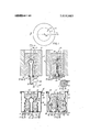
- FIG. 1 represents a top view of a candle in a mold
- FIG. 2 a cut away and sectioned side view taken along line 22 of FIG. 1 showing detail of a candle and candle mold system with an interior cavity mold bladder in the inflated state;
- FIG. 3 a cut away and sectioned side view similar to FIG. 2 with the interior cavity mold bladder in the collapsed state;
- FIG. 4 a partial top plan view from line 4-4 of FIG. 3 of the interior cavity mold bladder showing candle .wick end hold grasper detail;
- FIG. 5 a cut away and sectioned side view such as that of FIG. 2 showing detail of a candle and candle mold system with both an interior cavity mold bladder and an external mold bladder in the inflated state;
- FIG. 6 a cut away and sectioned side view similar to FIG. 5 with both the interior cavity mold bladder and the external mold bladder in the collapsed state.
- the candle of FIGS. 1, 2, and 3 is shown to have a wax body 11 cast in a mold system 12 including an outer cylindrical shell 13, that, in some instances, would have a severable half section (detail not shown) for easy candle removal from the mold shell 13.
- the mold system 12 also includes an inflatable and collapsible internal cavity molding bladder 14 that is equipped with an enlarged portion 15 larger in diameter, when inflated, than the shank 16 of the mold bladder 14.
- the shank 16 of the mold bladder 14 extends through opening 17 in mold system bottom plate 18 to an enlarged annular lip edge 19 held in place within opening 20 of a cap 21 fastened to bottom plate 18 as by screws 22.
- a fluid conduit tube 23 extends through opening 24 in cap 21 to fluid control valve 25 that is switchable between fluid pressure line 26 connected to a fluid pressure source (not shown) and fluid evacuation or vacuum line 27 connected to evacuation means (also not shown).
- the top of mold bladder 14 is provided with a plurality of wick 28 end grasping holder projections 29 that, while flexible to some degree with the mold bladder 14, assume a tightened grasping state about the enlarged lower end 30 of wick 28 when the mold bladder 14 is inflated. Then as the bladder 14 is evacuated and collapses the wick end grasping holder projections 29 relax their grip on the enlarged wick end 30. Thus, with the mold bladder 14 collapsed and of less diameter than the hole 31 molded .by the shank 16 of mold bladder 14 it may be easily removed from the candle body interior leaving an enlarged cavity portion 32 deep within the candle wax body.
- Wick 28 is suspended from a support member 33 that may be part of a wicking feed structure (detail not shown) until the candle wax poured into the mold system has hardened when it may be severed at an appropriate candle wick burning length.
- the mold system 12 also includes an external inflatable and collapsible mold bladder 34.
- the internal fluid chamber for mold bladder 34 is defined by cup member 35, having an outer cylindrical wall 36 and a bottom annular section 37 with a recess 38 where the bottom lip 39 of bladder 34 is retained in sealing confinement against the. bottom of mold system bottom plate 18, and the mold bladder 34 itself.
- the mold system 12 not only provides the means for producing candles with internal cavities having an enlarged innermost portion suitable for a great range of internal illumination effects but much more.
- the external bladder 34 may be formed with any variety of shapes concave and convex, rings and indentions in achieving additionally ornamental artistic results heightened by .light intensity variation through varied cast candle body wall thicknesses from the internally illuminated internal cavity of the candle. It should be noted that the flexible material of the external bladder 34 is capable of stretching through the area of an annular ring 43 producing an annular ring 44 cast in a candle body sufficiently to clear the candle body during removal from the mold system 12 when external bladder 34 is in the collapsed state.
- the flexible material used for the bladder 14 and bladder 34 in the respective embodiments must be a rubber or synthetic rubber, or plastic or other material capable of withstanding the temperature of molten wax (approximately 190 F or higher) being poured into the mold system.
- the bladders are of material withstanding the temperature cycling required and repeated cycling of inflation and evacuation collapse in repeated mold casting and removal of solidified cooled candles.
- an inflatable and deflation collapsible external and internal mold bladder said internal mold bladder shaped to desired internal cavity shape when inflated and deflation collapsed to an easy removable state when deflated; fluid pressure means; fluid evacuation means; valve control means for applying fluid pressure from said fluid pressure means and for connecting said mold bladderin fluid communication with said fluid evacuation means; and wherein said mold bladder is shaped with an enlarged portion and a smaller diameter shank when inflated to mold an internal cavity having an enlarged cavity portion and a shank-opening of smaller diameter than the enlarged cavity portion andextending from the enlarged cavity portion to the exterior of the object being molded.
- an inflatable and deflation collapsible mold bladder shaped to desired internal cavity shape when inflated and deflation collapsed to an easy removable state when deflated; fluid pressure means; fluid evacuation means; valve control means for applying fluid pressure from said fluid pressure means and for connecting said mold bladder in fluid communication with said fluid evacuation means; said mold bladder is shaped with an enlarged portion and a smaller diameter shank when inflated to mold an internal cavity having an enlarged cavity portion and a shank opening of smaller diameter than the enlarged cavity portion and extending from the enlarged cavity portion to the exterior of the object being molded; wherein said object being molded is a candle wax body; the mold bladder material is a material capable of withstanding the temperature range cycle of molten candle wax to ambient and repeated inflation and deflation cycles with repeated mold casting cycles; and wherein candle wick positioning and support means is provided on said mold bladder for'positioning a wick in each candle wax body being mold cast.
- said candle wick positioning and support means includes, an above the mold wick carrier; and lower wick end multiple grasping projections from said mold bladder positioned to firmly grasp the lower wick end when said mold bladder is in the inflated state and to relax grasping hold on the lower wick end as said mold bladder is deflation collapsed.
Landscapes
- Engineering & Computer Science (AREA)
- Mechanical Engineering (AREA)
- Chemical & Material Sciences (AREA)
- General Chemical & Material Sciences (AREA)
- Life Sciences & Earth Sciences (AREA)
- Chemical Kinetics & Catalysis (AREA)
- Oil, Petroleum & Natural Gas (AREA)
- Wood Science & Technology (AREA)
- Organic Chemistry (AREA)
- Fats And Perfumes (AREA)
- Moulds For Moulding Plastics Or The Like (AREA)
Abstract
An inflatable mold system for internally illuminated candles burnable from the top having a cavity within wax of the candle. The mold system includes irregularly shaped portions and an enlarged portion collapsible for easy removal from an internal cavity in the candle.
Description
United States Patent 1191 Andeweg [4 June 11, 1974 COLLAPSIBLE FLEXIBLE MATERIAL 1,177,240 3/1916 Gates .Q 425/010. 44
CANDLE D 4 3,136.831 6/1964 Zinn 264/316 X 3,239.59] 3/1966 Wendt 425/DIG. 44 Inventor: Fritz .1. Andeweg, 7737 Royal Ln., 3,258,384 6/1966 Scott 425/D1G. 44 Dallas, Tex. 75230 3,454,997 7/1969 Ligon et a1 425/D1G. 44 Filed J 13 1972 3,594,877 7/1971 Suda et al. 425/DIG. 44
[21] Appl. No.: 262,245 Primary Examine rRobert L. Spicer, Jr.
Attorney, Agent, or Firm-Warren H. Kintzinger [52] U.S. Cl 249/178, 249/152, 264/314,
425/D1G. 44, 425/803, 425/389 [57] ABSTRACT [51] Int. Cl. B29c 1/12, B28b 7/32 [58] new of Search 249/55 78, 152, 142; An inflatable mold system for internally Illuminated 264/314. 425/803 389 324 B 326 DIG 44 candles burnable from the top having a cavity within wax of the candle. The mold system includes irregu- [561 12143223411222??? 42214211232315:
e e o UNITED STATES PATENTS Gandhi 59,460 1l/l866 Ryder 425/803 1,142,342 6/1915 McNeil 425/D1G. 44 6 Claims, 6 Drawing Figures COLLAPSIBLE FLEXIBLE MATERIAL CANDLE MOLD This invention relates in general to hollow wax candles adapted for internal illumination and, in particular, to an inflatable mold system for producing candles having an internal cavity. The internal illumination for hollow wax candles is such as presented in my co-pending US. Pat. application Ser. No. 212,107, filed Dec. 27, 1971 and titled Internally Illuminated Candle.
Internally illuminated candles are quite beautiful with an internal glow through candle wax of the candle created by light from an internal cavity within the candle wax. There are problems, however, in producing wax candle bodies having such internal cavities and particularly with such candles having additionally artistic ornamental shapings. Many light intensity varied artistic results are obtained with varied candle wall thicknesses from an internal cavity to the outer surface of a candle. Another requirement with internal cavity equipped candles is that of holding candle wicking in place as candle wax is being cast into candle bodies.
It is, therefore, a principal object of this invention to provide a flexible material candle mold bladder for producing internal cavities in cast candle wax bodies.
Another object is to provide such a candle mold bladder of irregular shape.
A further object is to provide a candle mold bladder for producing a candle wax body internal cavity having an enlarged portion deep within the wax body as the candle is cast.
Another object with such an inflatable mold system for casting candle wax bodies is to provide a candle wick end hold grasper on the top of an internal cavity mold bladder.
Still a further object is to provide an inflatable mold system for producing candles with an internal cavity portion and an external portion having artistic irregular shaping.
Features of the invention useful in accomplishing the above objects include, in an inflatable mold system for producing candles having an internal cavity, an inflatable candle internal cavity mold bladder connected to an inflation and deflation control system connected to and through a container within which candles are cast. Some of the internal cavity mold bladders are equipped with an enlarged upper (or innermost) portion that must be at least partially collapsed for removal from the internal cavity of cast candle bodies. Further, some internal cavity mold bladders are also equipped with a wick end grasping holder that exerts a pronounced grasping force on the wick end when the bladder is inflated and a wick end has been positioned in the grasping holder. An external inflatable mold bladder is also provided for the casting of some candle wax bodies that is equipped for providing various desired cast shapes to the candle body providing various candle wall thicknesses as may be desired. In many instances the external inflatable mold bladder is connected to the same inflation and deflation control system as the candle internal cavity mold bladder.
Specific embodiments representing what are presently regarded as the best modes of carrying out the invention are illustrated in the accompanying drawing wherein:
FIG. 1 represents a top view of a candle in a mold;
FIG. 2, a cut away and sectioned side view taken along line 22 of FIG. 1 showing detail of a candle and candle mold system with an interior cavity mold bladder in the inflated state;
FIG. 3, a cut away and sectioned side view similar to FIG. 2 with the interior cavity mold bladder in the collapsed state;
FIG. 4, a partial top plan view from line 4-4 of FIG. 3 of the interior cavity mold bladder showing candle .wick end hold grasper detail;
FIG. 5, a cut away and sectioned side view such as that of FIG. 2 showing detail of a candle and candle mold system with both an interior cavity mold bladder and an external mold bladder in the inflated state; and,
FIG. 6, a cut away and sectioned side view similar to FIG. 5 with both the interior cavity mold bladder and the external mold bladder in the collapsed state.
Referring to the drawing:
The candle of FIGS. 1, 2, and 3 is shown to have a wax body 11 cast in a mold system 12 including an outer cylindrical shell 13, that, in some instances, would have a severable half section (detail not shown) for easy candle removal from the mold shell 13. The mold system 12 also includes an inflatable and collapsible internal cavity molding bladder 14 that is equipped with an enlarged portion 15 larger in diameter, when inflated, than the shank 16 of the mold bladder 14. The shank 16 of the mold bladder 14 extends through opening 17 in mold system bottom plate 18 to an enlarged annular lip edge 19 held in place within opening 20 of a cap 21 fastened to bottom plate 18 as by screws 22. A fluid conduit tube 23 extends through opening 24 in cap 21 to fluid control valve 25 that is switchable between fluid pressure line 26 connected to a fluid pressure source (not shown) and fluid evacuation or vacuum line 27 connected to evacuation means (also not shown).
Referring also to FIG. 4 the top of mold bladder 14 is provided with a plurality of wick 28 end grasping holder projections 29 that, while flexible to some degree with the mold bladder 14, assume a tightened grasping state about the enlarged lower end 30 of wick 28 when the mold bladder 14 is inflated. Then as the bladder 14 is evacuated and collapses the wick end grasping holder projections 29 relax their grip on the enlarged wick end 30. Thus, with the mold bladder 14 collapsed and of less diameter than the hole 31 molded .by the shank 16 of mold bladder 14 it may be easily removed from the candle body interior leaving an enlarged cavity portion 32 deep within the candle wax body. Wick 28 is suspended from a support member 33 that may be part of a wicking feed structure (detail not shown) until the candle wax poured into the mold system has hardened when it may be severed at an appropriate candle wick burning length.
Referring now to the embodiment of FIGS. 5 and 6 portions of the candle 10' and of the mold system 12' the same or substantially the same as with the embodiment of FIGS. 1, 2, and 3 will be given either the same number or primed numbers as a matter of convenience. Here in addition to an inflatable and collapsible internal cavity molding bladder 14, substantially the same as with the embodiment of FIGS. 1, 2, and 3, the mold system 12 also includes an external inflatable and collapsible mold bladder 34. The internal fluid chamber for mold bladder 34 is defined by cup member 35, having an outer cylindrical wall 36 and a bottom annular section 37 with a recess 38 where the bottom lip 39 of bladder 34 is retained in sealing confinement against the. bottom of mold system bottom plate 18, and the mold bladder 34 itself. This is with an upper beaded sealing lip edge 40 of the bladder 34 placed in resil iently stressed sealing contact with the outer top end of wall 36 just below an outwardly extended wall lip edge 41. The internal fluid chamber of mold bladder 34 is in fluid communication with fluid conduit tube 23' through one or more fluid conduit tubes 42. Fluid conduit tube 23 also extends through opening 24 in cap 21', that may be bonded to bottom plate 18, and to fluid control valve 25 that is switchable between fluid pressure line 26 and fluid evacuation line 27.
The mold system 12 not only provides the means for producing candles with internal cavities having an enlarged innermost portion suitable for a great range of internal illumination effects but much more. The external bladder 34 may be formed with any variety of shapes concave and convex, rings and indentions in achieving additionally ornamental artistic results heightened by .light intensity variation through varied cast candle body wall thicknesses from the internally illuminated internal cavity of the candle. It should be noted that the flexible material of the external bladder 34 is capable of stretching through the area of an annular ring 43 producing an annular ring 44 cast in a candle body sufficiently to clear the candle body during removal from the mold system 12 when external bladder 34 is in the collapsed state. Obviously, the flexible material used for the bladder 14 and bladder 34 in the respective embodiments must be a rubber or synthetic rubber, or plastic or other material capable of withstanding the temperature of molten wax (approximately 190 F or higher) being poured into the mold system. Further, the bladders are of material withstanding the temperature cycling required and repeated cycling of inflation and evacuation collapse in repeated mold casting and removal of solidified cooled candles.
Whereas this invention is illustrated and described with respect to a plurality of embodiments thereof, it should be realized that various changes may be made without departing from the essential contributions to the art made by the teachings hereof.
I claim:
1. In an inflatable mold system for the casting of objects having an internal cavity: an inflatable and deflation collapsible external and internal mold bladder, said internal mold bladder shaped to desired internal cavity shape when inflated and deflation collapsed to an easy removable state when deflated; fluid pressure means; fluid evacuation means; valve control means for applying fluid pressure from said fluid pressure means and for connecting said mold bladderin fluid communication with said fluid evacuation means; and wherein said mold bladder is shaped with an enlarged portion and a smaller diameter shank when inflated to mold an internal cavity having an enlarged cavity portion and a shank-opening of smaller diameter than the enlarged cavity portion andextending from the enlarged cavity portion to the exterior of the object being molded.
2. The inflatable mold system of claim 1 wherein said inflatable and deflatable external mold bladder section is shaped to mold desired shaping on the exterior of mold cast objects; fluid communication and valve control means for applying fluid pressure from said fluid pressure means and for connecting said external mold bladder section in fluid communication with said fluid evacuation means.
3. In an inflatable mold system for the casting of objects having an internal cavity: an inflatable and deflation collapsible mold bladder shaped to desired internal cavity shape when inflated and deflation collapsed to an easy removable state when deflated; fluid pressure means; fluid evacuation means; valve control means for applying fluid pressure from said fluid pressure means and for connecting said mold bladder in fluid communication with said fluid evacuation means; said mold bladder is shaped with an enlarged portion and a smaller diameter shank when inflated to mold an internal cavity having an enlarged cavity portion and a shank opening of smaller diameter than the enlarged cavity portion and extending from the enlarged cavity portion to the exterior of the object being molded; wherein said object being molded is a candle wax body; the mold bladder material is a material capable of withstanding the temperature range cycle of molten candle wax to ambient and repeated inflation and deflation cycles with repeated mold casting cycles; and wherein candle wick positioning and support means is provided on said mold bladder for'positioning a wick in each candle wax body being mold cast.
4. The inflatable mold system of claim 3, wherein said candle wick positioning and support means includes, an above the mold wick carrier; and lower wick end multiple grasping projections from said mold bladder positioned to firmly grasp the lower wick end when said mold bladder is in the inflated state and to relax grasping hold on the lower wick end as said mold bladder is deflation collapsed.
5. The inflatable mold system of claim 3, wherein the mold system also includes an inflatable and deflatable external mold bladder section shaped to mold desired shaping on the exterior of candle wax bodies being mold cast.
6. The inflatable mold system of claim 5, including fluid communication means with valve control means for applying fluid pressure from said fluid pressure means and for connecting said external mold bladder
Claims (6)
1. In an inflatable mold system for the casting of objects having an internal cavity: an inflatable and deflation collapsible external and internal mold bladder, said internal mold bladder shaped to desired internal cavity shape when inflated and deflation collapsed to an easy removable state when deflated; fluid pressure means; fluid evacuation means; valve control means for applying fluid pressure from said fluid pressure means and for connecting said mold bladder in fluid communication with said fluid evacuation means; and wherein said mold bladder is shaped with an enlarged portion and a smaller diameter shank when inflated to mold an internal cavity having an enlarged cavity portion and a shank opening of smaller diameter than the enlarged cavity portion and extending from the enlarged cavity portion to the exterior of the object being molded.
2. The inflatable mold system of claim 1 wherein said inflatable and deflatable external mold bladder section is shaped to mold desired shaping on the exterior of mold cast objects; fluid communication and valve control means for applying fluid pressure from said fluid pressure means and for connecting said external mold bladder section in fluid communication with said fluid evacuation means.
3. In an inflatable mold system for the casting of objects having an internal cavity: an inflatable and deflation collapsible mold bladder shaped to desired internal cavity shape when inflated and deflation collapsed to an easy removable state when deflated; fluid pressure means; fluid evacuation means; valve control means for applying fluid pressure from said fluid pressure means and for connecting said mold bladder in fluid communication with said fluid evacuation means; said mold bladder is shaped with an enlarged portion and a smaller diameter shank when inflated to mold an internal cavity having an enlarged cavity portion and a shank opening of smaller diameter than the enlaRged cavity portion and extending from the enlarged cavity portion to the exterior of the object being molded; wherein said object being molded is a candle wax body; the mold bladder material is a material capable of withstanding the temperature range cycle of molten candle wax to ambient and repeated inflation and deflation cycles with repeated mold casting cycles; and wherein candle wick positioning and support means is provided on said mold bladder for positioning a wick in each candle wax body being mold cast.
4. The inflatable mold system of claim 3, wherein said candle wick positioning and support means includes, an above the mold wick carrier; and lower wick end multiple grasping projections from said mold bladder positioned to firmly grasp the lower wick end when said mold bladder is in the inflated state and to relax grasping hold on the lower wick end as said mold bladder is deflation collapsed.
5. The inflatable mold system of claim 3, wherein the mold system also includes an inflatable and deflatable external mold bladder section shaped to mold desired shaping on the exterior of candle wax bodies being mold cast.
6. The inflatable mold system of claim 5, including fluid communication means with valve control means for applying fluid pressure from said fluid pressure means and for connecting said external mold bladder section in fluid communication with said evacuation means.
Priority Applications (1)
| Application Number | Priority Date | Filing Date | Title |
|---|---|---|---|
| US00262245A US3815863A (en) | 1972-06-13 | 1972-06-13 | Collapsible flexible material candle mold |
Applications Claiming Priority (1)
| Application Number | Priority Date | Filing Date | Title |
|---|---|---|---|
| US00262245A US3815863A (en) | 1972-06-13 | 1972-06-13 | Collapsible flexible material candle mold |
Publications (1)
| Publication Number | Publication Date |
|---|---|
| US3815863A true US3815863A (en) | 1974-06-11 |
Family
ID=22996772
Family Applications (1)
| Application Number | Title | Priority Date | Filing Date |
|---|---|---|---|
| US00262245A Expired - Lifetime US3815863A (en) | 1972-06-13 | 1972-06-13 | Collapsible flexible material candle mold |
Country Status (1)
| Country | Link |
|---|---|
| US (1) | US3815863A (en) |
Cited By (28)
| Publication number | Priority date | Publication date | Assignee | Title |
|---|---|---|---|---|
| US3980269A (en) * | 1975-01-20 | 1976-09-14 | Precision Flexmold, Inc. | Molding apparatus including a one-piece flexible mold having male and female forming members |
| US3982721A (en) * | 1975-01-20 | 1976-09-28 | Precision Flexmold, Inc. | Molding apparatus including a one-piece flexible mold deformable by fluid pressure differential |
| US4022862A (en) * | 1975-02-21 | 1977-05-10 | Hallmark Cards, Incorporated | Method of molding an article in an expansible mold and removing the article from the mold |
| US4027845A (en) * | 1975-04-28 | 1977-06-07 | Precision Flexmold, Inc. | Flexible mold including rigid encapsulated mandrel |
| US4093175A (en) * | 1973-10-03 | 1978-06-06 | Precision Flexmold, Inc. | Distensible elastomeric molds |
| US4100249A (en) * | 1975-11-28 | 1978-07-11 | Scolarma | Method of and apparatus for molding a receptacle |
| US4123215A (en) * | 1972-11-22 | 1978-10-31 | Kodama Kagaku Kohyo K. K. | Vacuum forming apparatus |
| US4202856A (en) * | 1977-09-30 | 1980-05-13 | Rockwell International Corporation | Graphite-epoxy molding method |
| FR2443324A1 (en) * | 1978-12-04 | 1980-07-04 | Bertin & Cie | Dilatant rubber moulds for fragile castings such as lipsticks - for ease of disengaging and cooling the moulding |
| US4212621A (en) * | 1979-06-21 | 1980-07-15 | Michelotti Paul E | Bladder molding |
| US4802839A (en) * | 1986-03-20 | 1989-02-07 | Yoshiyuki Corporation | Apparatus for producing cast products |
| US4854843A (en) * | 1987-06-13 | 1989-08-08 | Asahi Denka Kogyo K. K. | Apparatus for producing cast products |
| WO1991003363A1 (en) * | 1989-08-30 | 1991-03-21 | Karl Martin De Porteous | Moulding method |
| EP0503612A1 (en) * | 1991-03-14 | 1992-09-16 | Akutagawa Confectionary Co., Ltd. | Elastic mold and method for producing molded product using such mold |
| US5858295A (en) * | 1996-12-30 | 1999-01-12 | Johnson & Johnson Professional, Inc. | Method of injection molding a part using an inflatable mold core |
| WO1999046096A1 (en) * | 1998-03-10 | 1999-09-16 | Inteiss | Mould produced by at least two inflatable structures |
| US5971742A (en) * | 1996-09-18 | 1999-10-26 | Pyramid Composites Manufacturing Limited Partnership | Apparatus for molding composite articles |
| US6143215A (en) * | 1996-09-18 | 2000-11-07 | Vec Technology, Inc. | Method and apparatus for molding composite articles |
| WO2002047882A1 (en) * | 2000-12-11 | 2002-06-20 | Xanadu Candle International, Limited | Elastic mold and method of molding for undercut articles |
| WO2003000476A1 (en) * | 2001-06-22 | 2003-01-03 | Josef Wagner | Method and device for pressure slip casting |
| US6623672B2 (en) | 2000-10-03 | 2003-09-23 | Vec Technology Inc. | Method and apparatus for molding composite articles |
| US20040028563A1 (en) * | 2002-05-14 | 2004-02-12 | Chris Cunningham | Silicone mould tool |
| US20050184416A1 (en) * | 2004-01-23 | 2005-08-25 | Mccollum Robert P. | Method and apparatus for molding composite articles |
| US20080185754A1 (en) * | 2007-01-19 | 2008-08-07 | John Wirt | Method and apparatus for molding composite articles |
| DE102013004047A1 (en) * | 2013-03-08 | 2014-09-11 | Dorst Technologies Gmbh & Co. Kg | Press arrangement and method for pressing a pressed part |
| US20150017351A1 (en) * | 2013-07-12 | 2015-01-15 | Jay Markel | Method for Making Sculptural Interior in a Vessel and Vessels Produced Thereby |
| US20150375440A1 (en) * | 2014-06-26 | 2015-12-31 | Zamqua Holding B.V. | Mold for forming a hollow body and inflatable body |
| US9751256B2 (en) | 2014-01-20 | 2017-09-05 | Lockheed Martin Corporation | Joint molding apparatus |
Citations (8)
| Publication number | Priority date | Publication date | Assignee | Title |
|---|---|---|---|---|
| US59460A (en) * | 1866-11-06 | Improvement in tubular plungers for candle-molds | ||
| US1142342A (en) * | 1910-02-09 | 1915-06-08 | John Douglas Company | Method for molding clay or similar material. |
| US1177240A (en) * | 1913-02-07 | 1916-03-28 | Major E Gates | Method of molding clay articles. |
| US3136831A (en) * | 1961-07-14 | 1964-06-09 | United Aircraft Corp | Casting method |
| US3239591A (en) * | 1965-05-06 | 1966-03-08 | Pacific Clay Products | Method of making clay pipe |
| US3258384A (en) * | 1961-09-14 | 1966-06-28 | Babbitt Pipe Company Inc | Apparatus for forming tubular plastic members |
| US3454997A (en) * | 1965-11-30 | 1969-07-15 | Dickey Clay Mfg Co W S | Ceramic molding apparatus |
| US3594877A (en) * | 1969-10-24 | 1971-07-27 | Yuken Kogyo Co Ltd | Apparatus for manufacturing ceramic articles |
-
1972
- 1972-06-13 US US00262245A patent/US3815863A/en not_active Expired - Lifetime
Patent Citations (8)
| Publication number | Priority date | Publication date | Assignee | Title |
|---|---|---|---|---|
| US59460A (en) * | 1866-11-06 | Improvement in tubular plungers for candle-molds | ||
| US1142342A (en) * | 1910-02-09 | 1915-06-08 | John Douglas Company | Method for molding clay or similar material. |
| US1177240A (en) * | 1913-02-07 | 1916-03-28 | Major E Gates | Method of molding clay articles. |
| US3136831A (en) * | 1961-07-14 | 1964-06-09 | United Aircraft Corp | Casting method |
| US3258384A (en) * | 1961-09-14 | 1966-06-28 | Babbitt Pipe Company Inc | Apparatus for forming tubular plastic members |
| US3239591A (en) * | 1965-05-06 | 1966-03-08 | Pacific Clay Products | Method of making clay pipe |
| US3454997A (en) * | 1965-11-30 | 1969-07-15 | Dickey Clay Mfg Co W S | Ceramic molding apparatus |
| US3594877A (en) * | 1969-10-24 | 1971-07-27 | Yuken Kogyo Co Ltd | Apparatus for manufacturing ceramic articles |
Cited By (40)
| Publication number | Priority date | Publication date | Assignee | Title |
|---|---|---|---|---|
| US4123215A (en) * | 1972-11-22 | 1978-10-31 | Kodama Kagaku Kohyo K. K. | Vacuum forming apparatus |
| US4093175A (en) * | 1973-10-03 | 1978-06-06 | Precision Flexmold, Inc. | Distensible elastomeric molds |
| US3982721A (en) * | 1975-01-20 | 1976-09-28 | Precision Flexmold, Inc. | Molding apparatus including a one-piece flexible mold deformable by fluid pressure differential |
| US3980269A (en) * | 1975-01-20 | 1976-09-14 | Precision Flexmold, Inc. | Molding apparatus including a one-piece flexible mold having male and female forming members |
| US4022862A (en) * | 1975-02-21 | 1977-05-10 | Hallmark Cards, Incorporated | Method of molding an article in an expansible mold and removing the article from the mold |
| US4027845A (en) * | 1975-04-28 | 1977-06-07 | Precision Flexmold, Inc. | Flexible mold including rigid encapsulated mandrel |
| US4100249A (en) * | 1975-11-28 | 1978-07-11 | Scolarma | Method of and apparatus for molding a receptacle |
| US4202856A (en) * | 1977-09-30 | 1980-05-13 | Rockwell International Corporation | Graphite-epoxy molding method |
| FR2443324A1 (en) * | 1978-12-04 | 1980-07-04 | Bertin & Cie | Dilatant rubber moulds for fragile castings such as lipsticks - for ease of disengaging and cooling the moulding |
| US4212621A (en) * | 1979-06-21 | 1980-07-15 | Michelotti Paul E | Bladder molding |
| US4802839A (en) * | 1986-03-20 | 1989-02-07 | Yoshiyuki Corporation | Apparatus for producing cast products |
| US4854843A (en) * | 1987-06-13 | 1989-08-08 | Asahi Denka Kogyo K. K. | Apparatus for producing cast products |
| WO1991003363A1 (en) * | 1989-08-30 | 1991-03-21 | Karl Martin De Porteous | Moulding method |
| EP0503612A1 (en) * | 1991-03-14 | 1992-09-16 | Akutagawa Confectionary Co., Ltd. | Elastic mold and method for producing molded product using such mold |
| US6287493B1 (en) | 1996-09-18 | 2001-09-11 | Vec Technology, Inc. | Process for molding composite articles |
| US5971742A (en) * | 1996-09-18 | 1999-10-26 | Pyramid Composites Manufacturing Limited Partnership | Apparatus for molding composite articles |
| US6143215A (en) * | 1996-09-18 | 2000-11-07 | Vec Technology, Inc. | Method and apparatus for molding composite articles |
| US6257867B1 (en) | 1996-09-18 | 2001-07-10 | Vec Technology, Inc. | Apparatus for molding composite articles |
| US5858295A (en) * | 1996-12-30 | 1999-01-12 | Johnson & Johnson Professional, Inc. | Method of injection molding a part using an inflatable mold core |
| FR2775924A1 (en) * | 1998-03-10 | 1999-09-17 | Inteiss | Mold made by means of inflatable structure |
| WO1999046096A1 (en) * | 1998-03-10 | 1999-09-16 | Inteiss | Mould produced by at least two inflatable structures |
| US6623672B2 (en) | 2000-10-03 | 2003-09-23 | Vec Technology Inc. | Method and apparatus for molding composite articles |
| WO2002047882A1 (en) * | 2000-12-11 | 2002-06-20 | Xanadu Candle International, Limited | Elastic mold and method of molding for undercut articles |
| WO2003000476A1 (en) * | 2001-06-22 | 2003-01-03 | Josef Wagner | Method and device for pressure slip casting |
| US20040028563A1 (en) * | 2002-05-14 | 2004-02-12 | Chris Cunningham | Silicone mould tool |
| US7121519B2 (en) * | 2002-05-14 | 2006-10-17 | Perkinelmer International C.V. | Silicone mould tool |
| US20050184416A1 (en) * | 2004-01-23 | 2005-08-25 | Mccollum Robert P. | Method and apparatus for molding composite articles |
| US7553435B2 (en) | 2004-01-23 | 2009-06-30 | Vec Industries, L.L.C. | Method and apparatus for molding composite articles |
| US20080185754A1 (en) * | 2007-01-19 | 2008-08-07 | John Wirt | Method and apparatus for molding composite articles |
| US7785518B2 (en) | 2007-01-19 | 2010-08-31 | Vec Industries, L.L.C. | Method and apparatus for molding composite articles |
| US20100327496A1 (en) * | 2007-01-19 | 2010-12-30 | Vec Industries, L.L.C. | Method and apparatus for molding composite articles |
| US8845947B2 (en) | 2007-01-19 | 2014-09-30 | Vec Industries, L.L.C. | Method and apparatus for molding composite articles |
| DE102013004047A1 (en) * | 2013-03-08 | 2014-09-11 | Dorst Technologies Gmbh & Co. Kg | Press arrangement and method for pressing a pressed part |
| US20150017351A1 (en) * | 2013-07-12 | 2015-01-15 | Jay Markel | Method for Making Sculptural Interior in a Vessel and Vessels Produced Thereby |
| US9296633B2 (en) * | 2013-07-12 | 2016-03-29 | Jay Markel | Method for making sculptural interior in a vessel and vessels produced thereby |
| US9586848B2 (en) | 2013-07-12 | 2017-03-07 | Jay Markel | Method for making sculptural interior in a vessel and vessels produced thereby |
| US9751256B2 (en) | 2014-01-20 | 2017-09-05 | Lockheed Martin Corporation | Joint molding apparatus |
| US20150375440A1 (en) * | 2014-06-26 | 2015-12-31 | Zamqua Holding B.V. | Mold for forming a hollow body and inflatable body |
| US10456971B2 (en) * | 2014-06-26 | 2019-10-29 | Zamqua Holding B.V. | Mold for forming a hollow body and inflatable body |
| US11034075B2 (en) | 2014-06-26 | 2021-06-15 | Zamqua Holding B.V. | Mold for forming a hollow body and inflatable body |
Similar Documents
| Publication | Publication Date | Title |
|---|---|---|
| US3815863A (en) | Collapsible flexible material candle mold | |
| KR19990071518A (en) | Improved container. | |
| US3089185A (en) | Method and apparatus for manufacturing hollow plastic objects | |
| GB1202728A (en) | Method and apparatus for forming hollow articles from a blank of organic polymeric material by cold-forming and articles thus formed | |
| HU905282D0 (en) | Detaching tyres from mould | |
| US5662944A (en) | Sealing assembly for molds used for casting sanitary fixtures | |
| HK1047413B (en) | Releasing undercut moulded containers after a thermolforming process | |
| ES2124355T3 (en) | METHOD FOR MOLDING POLYETHYLENE BY INJECTION, STRETCHING AND BLOWING. | |
| FR2363430A1 (en) | TIRE VULCANIZATION PRESS | |
| US4027845A (en) | Flexible mold including rigid encapsulated mandrel | |
| GB1514944A (en) | Process and apparatus for forming hollow plastics article | |
| US4055620A (en) | Flexible mold and process | |
| JPS57206530A (en) | Manufacture of cam shaft | |
| ES2140577T3 (en) | A METHOD TO MANUFACTURE A PIPE OF THERMOPLASTIC MATERIAL. | |
| KR910004322A (en) | Central mechanism of tire vulcanizer | |
| US3900638A (en) | Inflatable christmas tree ornament | |
| GB1003299A (en) | Glass article and method of its formation | |
| US3980269A (en) | Molding apparatus including a one-piece flexible mold having male and female forming members | |
| US3741701A (en) | Frame for producing casting flasks | |
| JPS5624132A (en) | Blow molding method for synthetic resin hollow product with base cup | |
| KR100392110B1 (en) | Method for manufacturing a ceramic | |
| US1958859A (en) | Method of manufacturing glass reflectors | |
| ES478698A1 (en) | Forming a mouthpiece on a preform | |
| JPS55144134A (en) | Mold releasing of soft rubber or plastic product | |
| ATE219996T1 (en) | PRODUCTION OF A SUPPORT BODY |