US3784112A - Nozzle - Google Patents
Nozzle Download PDFInfo
- Publication number
- US3784112A US3784112A US00246284A US3784112DA US3784112A US 3784112 A US3784112 A US 3784112A US 00246284 A US00246284 A US 00246284A US 3784112D A US3784112D A US 3784112DA US 3784112 A US3784112 A US 3784112A
- Authority
- US
- United States
- Prior art keywords
- sprayer
- nozzle
- liquid
- shut
- recited
- Prior art date
- Legal status (The legal status is an assumption and is not a legal conclusion. Google has not performed a legal analysis and makes no representation as to the accuracy of the status listed.)
- Expired - Lifetime
Links
Images

Classifications
-
- B—PERFORMING OPERATIONS; TRANSPORTING
- B05—SPRAYING OR ATOMISING IN GENERAL; APPLYING FLUENT MATERIALS TO SURFACES, IN GENERAL
- B05B—SPRAYING APPARATUS; ATOMISING APPARATUS; NOZZLES
- B05B1/00—Nozzles, spray heads or other outlets, with or without auxiliary devices such as valves, heating means
- B05B1/14—Nozzles, spray heads or other outlets, with or without auxiliary devices such as valves, heating means with multiple outlet openings; with strainers in or outside the outlet opening
- B05B1/16—Nozzles, spray heads or other outlets, with or without auxiliary devices such as valves, heating means with multiple outlet openings; with strainers in or outside the outlet opening having selectively- effective outlets
-
- B—PERFORMING OPERATIONS; TRANSPORTING
- B05—SPRAYING OR ATOMISING IN GENERAL; APPLYING FLUENT MATERIALS TO SURFACES, IN GENERAL
- B05B—SPRAYING APPARATUS; ATOMISING APPARATUS; NOZZLES
- B05B1/00—Nozzles, spray heads or other outlets, with or without auxiliary devices such as valves, heating means
- B05B1/12—Nozzles, spray heads or other outlets, with or without auxiliary devices such as valves, heating means capable of producing different kinds of discharge, e.g. either jet or spray
Definitions
- ABSTRACT [30] Foreign Application Priorit Data
- a nozzle to provide either a weak dispersed jet or a Apr. 27 1971 France 7116458 Stmng concentrated jet Comprises a Sprayer with stages in the form of hollow rings joined together, 52 us. 01 239/443 239/447 239/448 eeeh ring having the Same inner diameter as 239/563 ers, the stages having slant perforations for the emis- 51 Int.
- the nozzle which is the object of the present invention makes it possible to avoid these disadvantages in a simple and efficient manner: in fact, it renders possible the adjustment of the dispersion or the intensity of the jet according to the desired use, and may be fitted to practically all water supplies.
- Such a nozzle may be used for ordinary showers (douches) intimate or dental hygiene, domestic cleaning and the like.
- the nozzle comprises two main parts. One is pierced with small holes and forms the sprayer, and the other, introduced into the first and receiving the water supply, constitutes the member for adjusting the stop valve due to a regulator with which it is provided.
- the sprayer has an end for projecting the water jet, which end is formed from several stages, three for example, each pierced with holes directed forwardly, forming angles along the longitudinal axis of the sprayer which progressively diminish towards the end of the sprayer.
- the bore of the sprayer within its body and between its stages, as far as the end stage, is such that it allows a passage for a shut-off member and, in particular, for the regulator which the latter comprises the water feed being effected through the interior of the said shut-off member and regulator, the latter having a tubular form.
- a lug connected to the body of the shut-off adjusting member, slides in a helical groove in the body of the sprayer so that variations in the relative positions of the said member and the sprayer may be made by relative rotation of the parts.
- the groove has level stretches or positioning means, such as perforations, for receiving the lug; these level stretches or recesses are disposed in such manner that when the lug rests on or in one of them, the shutoff member leaves all the stages of the sprayer open or progressively shuts off one or more of them.
- a flexible ring is disposed in and projecting from a groove on the sprayer.
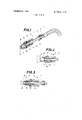
- FIG. 1 is a perspective view of a nozzle mounted on a hose-pipe, in part section taken through its longitudinal axis,
- FIG. 2 is a section of part of the nozzle shown in FIG. 1 in a position to show its components
- FIG. 3 is a section of a nozzle according to FIG. 2 shown in full, with its components in another position,
- FIG. 4 is a section of part of the jet showing a detail of the sprayer of the nozzle according to FIG. 1,
- FIG. 5 is a developed view of an embodiment of the ramp in which there slides the adjuster of the nozzle shown in FIG. 1,
- FIG. 6 is a section of another embodiment of the nozzle sprayer according to the present invention.
- FIG. 7 is a developed view of an embodiment of a ramp in which there slides the adjusting lug of the nozzle according to FIG. 6,
- a nozzle is connected to a flexible water supply tube 2 by means of a knurled nut 3 screwed on the threaded end 4 of a shut-off member 5.
- the shut-off member 5 comprises a tubular cylindrical regulator 10 located with its end 11 abutting a shoulder 12 in which a lug 13 is secured; the sprayer 14 is slipped on the regulator 10, the shoulder 12 of the shut-off member 5 permitting variation of the relative positions of the sprayer 14 and the shut-off member 5 through its bore 17.
- the lug 13 on the shut-off member runs in a helicoidal groove 15 of the jet such that rotation of the sprayer 14 on the shut-off member 5 determines the relative positions thereof.
- the sprayer 14 comprises a part 16 formed as a plurality of stages each pierced with an annular arrangement of holes, 20, 21 and 22, respectively, each of these stages being closed off in succession, if desired, by the regulator 10 of the shut-off member 5.
- the sprayer 14 is moved in the direction 30 on the shut-off member 5 by rotation of a half-turn of the shut-off member 5 into a position such that the water outlet to the first stage 20 is closed by the regulator 10 blocking the bore 32 of the sprayer.
- the cone of spray through the stages 21 and 22 subtends a solid angle 31 and this spray has increased force.
- the shutoff member 5 shuts off water from the second stage 21 by its regulator 10, blocking the bore 33 of the sprayer; the spray is produced within an even more reduced angle 35 and with increased force.
- a further rotation of the sprayer on the shut-off valve 5 in the same direction brings the joint face 25 to bear against the base 54 (FIG. 4) of the sprayer, shutting off water from the ring of holes 26, the flow of water now being confined to the holes 27, producing a jet substantially parallel to the axis 28 of the sprayer, this jet being of great force on account of the reduced cross-section of the jet.
- the holes formed in the stages 20, 21, 22, of the sprayer 14 have axes of different angular inclination such that the widest spray cone of the jet is obtained when the water flows through the holes of the three stages along the axes 40, 42, 43 and 41 respectively.
- the more the sprayer is shut-off the more the spray cone is reduced until this spray is only effected through the holes 27 along the axis 41, the jet then being substantially co-axial with the axis 28 of the sprayer. It is obvious that the more the spray cone closes, the more the crosssection of the water flow is reduced and the more the force of the jet is increased.
- level portions 50, 51, 52 and 53, in FIG. 5, are formed on the helicoidal groove 15, each respectively corresponding to a position for shutting off a stage of the sprayer, and hence to a particular spray cone and jet force.
- the level portion 50 corresponds to a position of the nozzle such as that shown in FIG. 1, the level portion 51 to a position such as that shown in FIG. 2, the level portion 52 to a position such as that shown in FIG. 3 and the level portion 53 to a position of the sprayer such that the shut-off member holds the end face of its regulator 10, against the base 54 of part 20, FIG. 4, forming a jet flowing only through the holes 27.
- the helicoidal groove 60 of the sprayer 61 is formed by a helical thread of constant width.
- the levels representing means of retaining the sprayer such as those shown in FIG. are replaced by perforations, 62, 63, 64 and 65, respectively, formed radially in the body of the sprayer, each of these perforations corresponding to one of the positions of adjustment and permitting the engagement therein of the lug 13 under the effect of water pressure.
- the perforations 62, 63 and 64 are spaced apart by the value of half-a-turn of the sprayer, whilst 65 is at a smaller distance corresponding to a shorter movement of the sprayer on the shut-off member.
- the shoulder of the shut-off member is threaded and receives the sprayer through a corresponding threaded bore thereof. Adjustments are then obtained by screwing and unscrewing the sprayer on the shut-off member. 7
- the part of the sprayer comprising perforations is obtained by rolling, thus making it possible to prevent the bores separating the stages from having sharp edges in the passage of the shut-off regulator.
- the nozzle may be provided with' holding means, and adapted to any water supply point by means of a hose connection member.
- a nozzle adjustable to form ajet of liquid of variable dispersion and force comprisingz a sprayer having a plurality of stages, each stage being pierced with a ring of holes and each stage defining an aperture, all of said apertures being of the same diameter; an elongated member through the interior of which said liquid is fed; a regulator on said member adapted successively to shut off or open a supply of liquid to said holes of successive stages; and means'for longitudinally displacing said sprayer on said member to effect said shutting or opening.
- shutoff member has a screw thread, said sprayer being adjustable in position on said thread.
- a nozzle adjustable to form a jet of liquid of variable dispersion and force comprising: a sprayer having a plurality of stages each pierced 'with a ring of holes, said sprayer defining a helical groove; an elongated member through the interior of which said liquid is fed; a regulator on said member adapted successively to shut off or open a supply of liquid to said holes of successive stages, said regulator having a lug running in said groove; and means for longitudinally displacing said sprayer on said member to effect said shutting or opening.
Landscapes
- Nozzles (AREA)
Abstract
A nozzle to provide either a weak dispersed jet or a strong concentrated jet comprises a sprayer with stages in the form of hollow rings joined together, each ring having the same inner diameter as the others, the stages having slant perforations for the emission of liquid. The sprayer slides on a tube supplying the liquid, the tube end acting as a regulator. If the tube is only just inserted in the sprayer, all the perforations of all the stages omit a diffused spray. As the regulator is further inserted in the sprayer, stages are progressively cut out until only the end one, pierced with a few axial holes, emits liquid in a concentrated jet.
Description
United States Patent 1 1 3,784,112 Collignon Jan. 8, 1974 NOZZLE 2,675,270 4 1954 Clougherty et a1. 239 444 76 Inventor: Jean Colli on Vill Fl d l 1 bois f f 68 Primary ExaminerM. Henson Wood, Jr. Assistant Examiner-John J. Love Flledi AP 1972 Att0meyArthur Schwartz et al. [21] Appl, No.: 246,284
[57] ABSTRACT [30] Foreign Application Priorit Data A nozzle to provide either a weak dispersed jet or a Apr. 27 1971 France 7116458 Stmng concentrated jet Comprises a Sprayer with stages in the form of hollow rings joined together, 52 us. 01 239/443 239/447 239/448 eeeh ring having the Same inner diameter as 239/563 ers, the stages having slant perforations for the emis- 51 Int. Cl B05b l/16 of liquid- The Sprayer Slides a tube Supplying 58 Field of Search 239/394 443-449 e liquid the tube end eeeeg as e reguleter- If the 239/539 562 tube is only just inserted in the sprayer, all the perforations of all the stages omit a diffused spray. As the [56] References Cited regulator is further inserted in the sprayer, stages are progressively cut out until only the end one, pierced UNITED STATES PATENTS with a few axial holes, emits liquid in a concentrated 2,359,455 10/1944 Williamson 239 449 jet 3,241,773 3/1966 Travis 239/443 X 577,616 2/1897 Day 239/444 9 Claims, 7 Drawing Figures NOZZLE The present invention concerns an adjustable nozzle which can form a jet of water of varying dispersion and force.
Conventional nozzles, comprising a rose, have a sprayer pierced with small holes connected to the water supply. These nozzles, having no means for adjusting the amplitude and power of the jet, prove to be not very practical and of restricted use; in fact, when a dispersed and gentle spray of water is required, the only means of adjustment is to control the water flow by a tap, which may not be satisfactory, as such adjustment is crude. Again, in cases where a powerful jet is desired, as for massage, any excessive dispersion of the jet of water is undesirable.
Furthermore, since these nozzles are intended for particular uses such as ordinary shower baths, it is not possible to adapt them readily to other uses.
The nozzle which is the object of the present invention makes it possible to avoid these disadvantages in a simple and efficient manner: in fact, it renders possible the adjustment of the dispersion or the intensity of the jet according to the desired use, and may be fitted to practically all water supplies. Such a nozzle may be used for ordinary showers (douches) intimate or dental hygiene, domestic cleaning and the like.
In a preferred embodiment of the invention, the nozzle comprises two main parts. One is pierced with small holes and forms the sprayer, and the other, introduced into the first and receiving the water supply, constitutes the member for adjusting the stop valve due to a regulator with which it is provided. The sprayer has an end for projecting the water jet, which end is formed from several stages, three for example, each pierced with holes directed forwardly, forming angles along the longitudinal axis of the sprayer which progressively diminish towards the end of the sprayer. The bore of the sprayer, within its body and between its stages, as far as the end stage, is such that it allows a passage for a shut-off member and, in particular, for the regulator which the latter comprises the water feed being effected through the interior of the said shut-off member and regulator, the latter having a tubular form.
A lug, connected to the body of the shut-off adjusting member, slides in a helical groove in the body of the sprayer so that variations in the relative positions of the said member and the sprayer may be made by relative rotation of the parts.
In order to prevent the pressure of the water forcing back the shut-off member in the sprayer, the groove has level stretches or positioning means, such as perforations, for receiving the lug; these level stretches or recesses are disposed in such manner that when the lug rests on or in one of them, the shutoff member leaves all the stages of the sprayer open or progressively shuts off one or more of them.
According to the positions of the shut-off member in the sprayer, a more or less spread spray cone is obtained, with a varying degree of pressure.
To prevent the nozzle from banging against an item of sanitary-ware such as a wash-basin or bath, and possibly damaging it, a flexible ring is disposed in and projecting from a groove on the sprayer.
The present invention will be more clearly understood with reference to the following description relating to the attached schematic drawings, in which:
FIG. 1 is a perspective view of a nozzle mounted on a hose-pipe, in part section taken through its longitudinal axis,
FIG. 2 is a section of part of the nozzle shown in FIG. 1 in a position to show its components,
FIG. 3 is a section of a nozzle according to FIG. 2 shown in full, with its components in another position,
FIG. 4 is a section of part of the jet showing a detail of the sprayer of the nozzle according to FIG. 1,
FIG. 5 is a developed view of an embodiment of the ramp in which there slides the adjuster of the nozzle shown in FIG. 1,
FIG. 6 is a section of another embodiment of the nozzle sprayer according to the present invention,
FIG. 7 is a developed view of an embodiment of a ramp in which there slides the adjusting lug of the nozzle according to FIG. 6,
In FIG. 1, a nozzle is connected to a flexible water supply tube 2 by means of a knurled nut 3 screwed on the threaded end 4 of a shut-off member 5. The shut-off member 5 comprises a tubular cylindrical regulator 10 located with its end 11 abutting a shoulder 12 in which a lug 13 is secured; the sprayer 14 is slipped on the regulator 10, the shoulder 12 of the shut-off member 5 permitting variation of the relative positions of the sprayer 14 and the shut-off member 5 through its bore 17. The lug 13 on the shut-off member runs in a helicoidal groove 15 of the jet such that rotation of the sprayer 14 on the shut-off member 5 determines the relative positions thereof. The sprayer 14 comprises a part 16 formed as a plurality of stages each pierced with an annular arrangement of holes, 20, 21 and 22, respectively, each of these stages being closed off in succession, if desired, by the regulator 10 of the shut-off member 5. A protective ring 23, of rubber, projecting from a recess on the sprayer, prevents any damage to the nozzle.
In FIG. 2, the sprayer 14 is moved in the direction 30 on the shut-off member 5 by rotation of a half-turn of the shut-off member 5 into a position such that the water outlet to the first stage 20 is closed by the regulator 10 blocking the bore 32 of the sprayer. The cone of spray through the stages 21 and 22 subtends a solid angle 31 and this spray has increased force. By causing further similar displacement of the sprayer 14, the shutoff member 5 shuts off water from the second stage 21 by its regulator 10, blocking the bore 33 of the sprayer; the spray is produced within an even more reduced angle 35 and with increased force.
A further rotation of the sprayer on the shut-off valve 5 in the same direction brings the joint face 25 to bear against the base 54 (FIG. 4) of the sprayer, shutting off water from the ring of holes 26, the flow of water now being confined to the holes 27, producing a jet substantially parallel to the axis 28 of the sprayer, this jet being of great force on account of the reduced cross-section of the jet.
With reference to FIG. 4 again, the holes formed in the stages 20, 21, 22, of the sprayer 14 have axes of different angular inclination such that the widest spray cone of the jet is obtained when the water flows through the holes of the three stages along the axes 40, 42, 43 and 41 respectively. The more the sprayer is shut-off, the more the spray cone is reduced until this spray is only effected through the holes 27 along the axis 41, the jet then being substantially co-axial with the axis 28 of the sprayer. It is obvious that the more the spray cone closes, the more the crosssection of the water flow is reduced and the more the force of the jet is increased. Since the water pressure in the jet tends to slide the sprayer off its shut-off member, such withdrawal of the sprayer and the shut-off member is avoided by forming level portions 50, 51, 52 and 53, in FIG. 5, on the helicoidal groove 15, each respectively corresponding to a position for shutting off a stage of the sprayer, and hence to a particular spray cone and jet force. On the ramp 15, the level portion 50 corresponds to a position of the nozzle such as that shown in FIG. 1, the level portion 51 to a position such as that shown in FIG. 2, the level portion 52 to a position such as that shown in FIG. 3 and the level portion 53 to a position of the sprayer such that the shut-off member holds the end face of its regulator 10, against the base 54 of part 20, FIG. 4, forming a jet flowing only through the holes 27.
According to an embodiment shown in FIGS. 6 and 7, the helicoidal groove 60 of the sprayer 61, is formed by a helical thread of constant width. The levels representing means of retaining the sprayer such as those shown in FIG. are replaced by perforations, 62, 63, 64 and 65, respectively, formed radially in the body of the sprayer, each of these perforations corresponding to one of the positions of adjustment and permitting the engagement therein of the lug 13 under the effect of water pressure.
The perforations 62, 63 and 64, are spaced apart by the value of half-a-turn of the sprayer, whilst 65 is at a smaller distance corresponding to a shorter movement of the sprayer on the shut-off member.
According to one embodiment of the invention (not shown) the shoulder of the shut-off member is threaded and receives the sprayer through a corresponding threaded bore thereof. Adjustments are then obtained by screwing and unscrewing the sprayer on the shut-off member. 7
Preferably, the part of the sprayer comprising perforations is obtained by rolling, thus making it possible to prevent the bores separating the stages from having sharp edges in the passage of the shut-off regulator.
Again, the nozzle may be provided with' holding means, and adapted to any water supply point by means of a hose connection member.
I claim:
1. A nozzle adjustable to form ajet of liquid of variable dispersion and force, comprisingz a sprayer having a plurality of stages, each stage being pierced with a ring of holes and each stage defining an aperture, all of said apertures being of the same diameter; an elongated member through the interior of which said liquid is fed; a regulator on said member adapted successively to shut off or open a supply of liquid to said holes of successive stages; and means'for longitudinally displacing said sprayer on said member to effect said shutting or opening.
2. A nozzle as recited in claim 1, wherein said regulator is a cylindrical tube fixed to said member.
3. A nozzle as recited in claim 1, wherein the aperture in the end stage of said sprayer is equal in diameter to that of the resultant jet.
4. A nozzle as recited in claim 1, wherein the axes of said holes in each stage form angles with the axis of said sprayer, said angles becoming more acute towards the end of said sprayer.
5. A nozzle as recited in claim 1, wherein said shutoff member has a screw thread, said sprayer being adjustable in position on said thread.
6. A nozzle as recited in claim 1, wherein said sprayer includes a projecting protective outer ring.
7. A nozzle adjustable to form a jet of liquid of variable dispersion and force, comprising: a sprayer having a plurality of stages each pierced 'with a ring of holes, said sprayer defining a helical groove; an elongated member through the interior of which said liquid is fed; a regulator on said member adapted successively to shut off or open a supply of liquid to said holes of successive stages, said regulator having a lug running in said groove; and means for longitudinally displacing said sprayer on said member to effect said shutting or opening.
8. A nozzle as recited in claim 7 wherein said groove has level portions corresponding to desired relative positions of said sprayer and said shut-off member.
9. A nozzle as recited in claim 7, wherein said groove has a constant pitch and includes recesses in which said lug engages under the action of liquid pressure, said recesses corresponding to predetermined relative positions of said sprayer and said shut-off member.
Claims (9)
1. A nozzle adjustable to form a jet of liquid of variable dispersion and force, comprising: a sprayer having a plurality of stages, each stage being pierced with a ring of holes and each stage defining an aperture, all of said apertures being of the same diameter; an elongated member through the interior of which said liquid is fed; a regulator on said member adapted successively to shut off or open a supply of liquid to said holes of successive stages; and means for longitudinally displacing said sprayer on said member to effect said shutting or opening.
2. A nozzle as recited in claim 1, wherein said regulator is a cylindrical tube fixed to said member.
3. A nozzle as recited in claim 1, wherein the aperture in the end stage of said sprayer is equal in diameter to that of the resultant jet.
4. A nozzle as recited in claim 1, wherein the axes of said holes in each stage form angles with the axis of said sprayer, said angles becoming more acute towards the end of said sprayer.
5. A nozzle as recited in claim 1, wherein said shut-off member has a screw thread, said sprayer being adjustable in position on said thread.
6. A nozzle as recited in claim 1, wherein said sprayer includes a projecting protective outer ring.
7. A nozzle adjustable to form a jet of liquid of variable dispersion and force, comprising: a sprayer having a plurality of stages each pierced with a ring of holes, said sprayer defining a helical groove; an elongated member through the interior of which said liquid is fed; a regulator on said member adapted successively to shut off or open a supply of liquid to said holes of successive stages, said regulator having a lug running in sAid groove; and means for longitudinally displacing said sprayer on said member to effect said shutting or opening.
8. A nozzle as recited in claim 7 wherein said groove has level portions corresponding to desired relative positions of said sprayer and said shut-off member.
9. A nozzle as recited in claim 7, wherein said groove has a constant pitch and includes recesses in which said lug engages under the action of liquid pressure, said recesses corresponding to predetermined relative positions of said sprayer and said shut-off member.
Applications Claiming Priority (1)
| Application Number | Priority Date | Filing Date | Title |
|---|---|---|---|
| FR7116458A FR2135887A5 (en) | 1971-04-27 | 1971-04-27 |
Publications (1)
| Publication Number | Publication Date |
|---|---|
| US3784112A true US3784112A (en) | 1974-01-08 |
Family
ID=9076576
Family Applications (1)
| Application Number | Title | Priority Date | Filing Date |
|---|---|---|---|
| US00246284A Expired - Lifetime US3784112A (en) | 1971-04-27 | 1972-04-21 | Nozzle |
Country Status (10)
| Country | Link |
|---|---|
| US (1) | US3784112A (en) |
| BR (1) | BR7202515D0 (en) |
| CA (1) | CA965817A (en) |
| CH (1) | CH546601A (en) |
| DE (1) | DE2221880C3 (en) |
| ES (1) | ES402857A1 (en) |
| FR (1) | FR2135887A5 (en) |
| GB (1) | GB1392982A (en) |
| IT (1) | IT961291B (en) |
| LU (1) | LU65257A1 (en) |
Cited By (8)
| Publication number | Priority date | Publication date | Assignee | Title |
|---|---|---|---|---|
| US3912173A (en) * | 1974-04-25 | 1975-10-14 | Donald F Robichaux | Formation flushing tool |
| US5765581A (en) * | 1996-07-25 | 1998-06-16 | Fisher & Paykel Limited | Variable geometry spray nozzle |
| AU698572B2 (en) * | 1995-07-27 | 1998-11-05 | Fisher & Paykel Appliances Limited | Variable geometry spray nozzle |
| US6758413B1 (en) * | 2003-03-14 | 2004-07-06 | Pao-Tien Chen | Sprinkler |
| US20060122563A1 (en) * | 2004-08-09 | 2006-06-08 | Elan Ziv | Applicator assembly for application of substances to a body orifice and cavity |
| US20120298781A1 (en) * | 2011-05-24 | 2012-11-29 | Baker Hughes Incorporated | Enhanced Penetration of Telescoping Fracturing Nozzle Assembly |
| US20130168474A1 (en) * | 2011-12-28 | 2013-07-04 | Eley Corporation | Adjustable Sprayer |
| US20140284403A1 (en) * | 2011-12-28 | 2014-09-25 | Eley Corporation | Adjustable sprayer |
Families Citing this family (2)
| Publication number | Priority date | Publication date | Assignee | Title |
|---|---|---|---|---|
| ES242901Y (en) * | 1979-04-25 | 1980-02-01 | SELECTOR DEVICE FOR WATER OUTLET. | |
| GB2330320A (en) * | 1997-10-17 | 1999-04-21 | Ernest Joscelyn Clerk | Water-dispensing nozzle |
Citations (4)
| Publication number | Priority date | Publication date | Assignee | Title |
|---|---|---|---|---|
| US577616A (en) * | 1897-02-23 | Hose-nozzle | ||
| US2359455A (en) * | 1943-06-02 | 1944-10-03 | Marine Specialty Company Inc | Fire extinguishing nozzle |
| US2675270A (en) * | 1952-01-15 | 1954-04-13 | John E Clougherty | Combined fog and solid or straight stream nozzle |
| US3241773A (en) * | 1964-02-14 | 1966-03-22 | Ralph L Travis | Combination hose nozzle |
Family Cites Families (1)
| Publication number | Priority date | Publication date | Assignee | Title |
|---|---|---|---|---|
| US3383051A (en) * | 1966-01-10 | 1968-05-14 | Speakman Co | Shower head |
-
1971
- 1971-04-27 FR FR7116458A patent/FR2135887A5/fr not_active Expired
-
1972
- 1972-04-13 GB GB1702672A patent/GB1392982A/en not_active Expired
- 1972-04-14 IT IT49623/72A patent/IT961291B/en active
- 1972-04-21 US US00246284A patent/US3784112A/en not_active Expired - Lifetime
- 1972-04-25 ES ES402857A patent/ES402857A1/en not_active Expired
- 1972-04-25 BR BR2515/72A patent/BR7202515D0/en unknown
- 1972-04-25 CH CH614272A patent/CH546601A/en not_active IP Right Cessation
- 1972-04-26 LU LU65257D patent/LU65257A1/xx unknown
- 1972-04-26 DE DE2221880A patent/DE2221880C3/en not_active Expired
- 1972-04-26 CA CA140,676A patent/CA965817A/en not_active Expired
Patent Citations (4)
| Publication number | Priority date | Publication date | Assignee | Title |
|---|---|---|---|---|
| US577616A (en) * | 1897-02-23 | Hose-nozzle | ||
| US2359455A (en) * | 1943-06-02 | 1944-10-03 | Marine Specialty Company Inc | Fire extinguishing nozzle |
| US2675270A (en) * | 1952-01-15 | 1954-04-13 | John E Clougherty | Combined fog and solid or straight stream nozzle |
| US3241773A (en) * | 1964-02-14 | 1966-03-22 | Ralph L Travis | Combination hose nozzle |
Cited By (11)
| Publication number | Priority date | Publication date | Assignee | Title |
|---|---|---|---|---|
| US3912173A (en) * | 1974-04-25 | 1975-10-14 | Donald F Robichaux | Formation flushing tool |
| AU698572B2 (en) * | 1995-07-27 | 1998-11-05 | Fisher & Paykel Appliances Limited | Variable geometry spray nozzle |
| US5765581A (en) * | 1996-07-25 | 1998-06-16 | Fisher & Paykel Limited | Variable geometry spray nozzle |
| US6758413B1 (en) * | 2003-03-14 | 2004-07-06 | Pao-Tien Chen | Sprinkler |
| US20060122563A1 (en) * | 2004-08-09 | 2006-06-08 | Elan Ziv | Applicator assembly for application of substances to a body orifice and cavity |
| US20120298781A1 (en) * | 2011-05-24 | 2012-11-29 | Baker Hughes Incorporated | Enhanced Penetration of Telescoping Fracturing Nozzle Assembly |
| US8720544B2 (en) * | 2011-05-24 | 2014-05-13 | Baker Hughes Incorporated | Enhanced penetration of telescoping fracturing nozzle assembly |
| US20130168474A1 (en) * | 2011-12-28 | 2013-07-04 | Eley Corporation | Adjustable Sprayer |
| US8794546B2 (en) * | 2011-12-28 | 2014-08-05 | Eley Corporation | Adjustable sprayer |
| US20140284403A1 (en) * | 2011-12-28 | 2014-09-25 | Eley Corporation | Adjustable sprayer |
| US9061298B2 (en) * | 2011-12-28 | 2015-06-23 | Eley Corporation | Adjustable sprayer |
Also Published As
| Publication number | Publication date |
|---|---|
| LU65257A1 (en) | 1972-07-14 |
| CA965817A (en) | 1975-04-08 |
| ES402857A1 (en) | 1975-04-16 |
| CH546601A (en) | 1974-03-15 |
| IT961291B (en) | 1973-12-10 |
| GB1392982A (en) | 1975-05-07 |
| BR7202515D0 (en) | 1973-05-03 |
| DE2221880B2 (en) | 1981-02-26 |
| DE2221880C3 (en) | 1981-11-12 |
| FR2135887A5 (en) | 1972-12-22 |
| DE2221880A1 (en) | 1972-11-09 |
Similar Documents
| Publication | Publication Date | Title |
|---|---|---|
| US4614303A (en) | Water saving shower head | |
| US3637143A (en) | Handle-controlled spray | |
| US3784112A (en) | Nozzle | |
| US4262371A (en) | Air-water outlet fitting | |
| US5217166A (en) | Rotor nozzle for a high-pressure cleaning device | |
| US6178570B1 (en) | Adjustable multi-nozzle rotating hydrotherapy jet system | |
| US6263522B1 (en) | Hydrotherapy jet with an extendable/retractable outlet | |
| US5657496A (en) | Two-axis rotating hydrotherapy jet with adjustable nozzle orientations | |
| US4349923A (en) | Jet nozzle assembly for therapy baths | |
| US2993655A (en) | Hose nozzle | |
| US3722800A (en) | Shuttle type diverter valve for use with handle controlled spray | |
| US4460519A (en) | Hydrotherapy jet unit | |
| US2974877A (en) | Shower heads | |
| US6561439B1 (en) | Dual closure nozzle | |
| US4928885A (en) | Nozzle device | |
| GB2089684A (en) | A nozzle with directional outlet jet of continuously changing direction | |
| US2145451A (en) | Jet for garden hose | |
| HU213775B (en) | Water supply head for eddy pools | |
| US3708124A (en) | Cement spray gun | |
| US2082061A (en) | Spray gun | |
| US1725381A (en) | Liquid atomizer | |
| US2605143A (en) | Hose nozzle | |
| US2658799A (en) | Shower head with volume control | |
| US4518122A (en) | Hand-operated hose for atomizing a liquid for the treatment of plants | |
| US2721762A (en) | Spray nozzle |