US3691875A - Chain driven spinning, make up and break out tongs - Google Patents
Chain driven spinning, make up and break out tongs Download PDFInfo
- Publication number
- US3691875A US3691875A US134554A US3691875DA US3691875A US 3691875 A US3691875 A US 3691875A US 134554 A US134554 A US 134554A US 3691875D A US3691875D A US 3691875DA US 3691875 A US3691875 A US 3691875A
- Authority
- US
- United States
- Prior art keywords
- chain
- motor
- run
- members
- pull
- Prior art date
- Legal status (The legal status is an assumption and is not a legal conclusion. Google has not performed a legal analysis and makes no representation as to the accuracy of the status listed.)
- Expired - Lifetime
Links
- 238000009987 spinning Methods 0.000 title abstract description 21
- 239000012530 fluid Substances 0.000 claims abstract description 43
- 230000006872 improvement Effects 0.000 claims description 2
- 230000002441 reversible effect Effects 0.000 description 23
- 230000007246 mechanism Effects 0.000 description 5
- 230000008901 benefit Effects 0.000 description 3
- 239000000969 carrier Substances 0.000 description 3
- 150000001875 compounds Chemical class 0.000 description 3
- 230000000694 effects Effects 0.000 description 3
- 230000009471 action Effects 0.000 description 2
- 230000008859 change Effects 0.000 description 2
- 230000008878 coupling Effects 0.000 description 2
- 238000010168 coupling process Methods 0.000 description 2
- 238000005859 coupling reaction Methods 0.000 description 2
- 210000005069 ears Anatomy 0.000 description 2
- 230000004044 response Effects 0.000 description 2
- 230000000717 retained effect Effects 0.000 description 2
- 101100264195 Caenorhabditis elegans app-1 gene Proteins 0.000 description 1
- JJLJMEJHUUYSSY-UHFFFAOYSA-L Copper hydroxide Chemical compound [OH-].[OH-].[Cu+2] JJLJMEJHUUYSSY-UHFFFAOYSA-L 0.000 description 1
- 239000002131 composite material Substances 0.000 description 1
- 230000006835 compression Effects 0.000 description 1
- 238000007906 compression Methods 0.000 description 1
- 230000001143 conditioned effect Effects 0.000 description 1
- 238000010276 construction Methods 0.000 description 1
- 230000001276 controlling effect Effects 0.000 description 1
- 238000010586 diagram Methods 0.000 description 1
- 238000005553 drilling Methods 0.000 description 1
- 229910000078 germane Inorganic materials 0.000 description 1
- 230000007935 neutral effect Effects 0.000 description 1
- 230000001105 regulatory effect Effects 0.000 description 1
- 230000035939 shock Effects 0.000 description 1
Images


Classifications
-
- E—FIXED CONSTRUCTIONS
- E21—EARTH OR ROCK DRILLING; MINING
- E21B—EARTH OR ROCK DRILLING; OBTAINING OIL, GAS, WATER, SOLUBLE OR MELTABLE MATERIALS OR A SLURRY OF MINERALS FROM WELLS
- E21B19/00—Handling rods, casings, tubes or the like outside the borehole, e.g. in the derrick; Apparatus for feeding the rods or cables
- E21B19/16—Connecting or disconnecting pipe couplings or joints
- E21B19/161—Connecting or disconnecting pipe couplings or joints using a wrench or a spinner adapted to engage a circular section of pipe
- E21B19/164—Connecting or disconnecting pipe couplings or joints using a wrench or a spinner adapted to engage a circular section of pipe motor actuated
Definitions
- ABSTRACT A tong for spinning, making up and breaking out pipe joints in which a chain drives the rotatable pipe gripping means and the chain is driven by a rotary fluid motor for spinning a pipe, and the motor is locked to anchor the chain during final make up and initial break out of the pipe joint, the chain being actuated by pressure responsive actuator cylinders engaging runs of the chain between the pipe gripping means and the rotary motor to apply high. make up and break out torque to the pipe gripping means.
- Power tongs have been provided for facilitating the making up and breaking out of the threaded joints or couplings of well pipe, such as drill pipe and easing.
- Such tongs generally, include a pipe gripping head or jaw mechanism which is actuated into gripping engagement with the pipe and then driven rotatively to rotate the pipe engaged thereby, while the complemental pipe is held stationary, say, by a back up tong in the case of drill pipe, or by the rotary table slips in the case of well casing.
- the present invention provides a novel and unobvious power pipe tong drive which employs the high torque final make up and initial break out characteristics of the tong of the above-mentioned application in combination with a high speed rotary motor drive for the chain to spin up and spin out joints of pipe.
- the present invention provides a power pipe tong in which the pipe gripping mechanism is driven by a continuous chain which is powered by a rotary fluid motor for spinning the pipe, and the rotary motor and motor drive to the chain are locked when the joint is to be finally made up or initially broken out, while a reciprocating pressure operated actuator cylinder acts on the chain intermediate the gripping mechanism and the point at which the chain is locked to apply high torque to the pipe gripping means to finally make up the joint or initially break out a joint.
- Such tong apparatus is capable of applying relatively high torque to the pipe with a mechanically simple system, which is, therefore, comparatively inexpensive, as compared with the usual change speed gear mechanism, and the drive is rugged and requires comparatively small space for the capabilities in pipe joint spinning, make up and break out.
- FIG. 1 is a top plan of a power tong made in accordance with the invention, with portions of the housing broken away, to expose the interior structure, with the gripping jaws retracted;
- FIG. 2 is a vertical section, as taken on the line 2-2 of FIG. 1;
- FIG. 3 is a view corresponding to FIG. 1 but showing the gripping jaws in pipe gripping positions and the actuator means shifted to break out a joint of pipe;
- FIG. 4 is an enlarged vertical section, as taken on the line 4-4 of FIG. 2, and showing a typical actuator slide construction
- FIG. 5 is a horizontal section, as taken on the line 5- 5 of FIG. 2, with parts broken away to show the reverse stop and brake means;
- FIG. 6 is an enlarged fragmentary, vertical section, as taken on the line 6-6 of FIG. 5;
- FIG. 7 is a fragmentary vertical section, as taken on the line 7-7 of FIG. 6, showing the reverse stop means in a make up condition;
- FIG. 8 is a view generally corresponding to FIG. 7, but showing the reverse stop means actuated to the break out condition
- FIG. 9 is a vertical section, as taken on line 9-9 of FIG. 7;
- FIG. 10 is a vertical section, as taken on the line 10- 10 of FIG. 8;
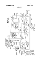
- FIG. 1 l is a schematic diagram of the control and operating system for the tong.
- the tong assembly comprises a body or housing H defining an opening 0 for a pipe and in which is rotatably supported pipe gripping means G, including a number of circumferentially spaced gripping jaws .I, carried by an inner, jaw-carrying ring or rotatable member 10, and actuatable radially of the assembly from retracted positions, as seen in FIG. 1, to pipe gripping positions, as seen in FIG.
- drive means including one or more drive chains 12, a fluid pressure operated, rotary, chain driving, spinning motor M, and, depending on whether the tong is being used to make up or break out pipe joints, break out actuator cylinder means B0 and a Y make up actuator cylinder means MU, each of which actuator cylinder means operatively engages a portion or run of the chain or chains 12 between the motor M and the outer ring 1 1, whereby extension of the respective cylinder means will apply a pull to the respective run of the chain and eflect angular movement of the outer ring 11 in one direction or the other, while the motor M or its chain drive shaft is locked by lock means L.
- the housing H comprises an annular body 20 to which is suitably affixed, as by fasteners 21, a top annular plate 22.
- a guide ring support 23 Centrally of the plate 22 is a guide ring support 23, attached to the plate 22 by fasteners 24 and having a guide insert 230 defining the open top of the pipe opening 0.
- a bottom plate 25, affixed to the body 20 by fasteners 26, combines with the body 20 and the top plate 22 to form an annular space in which the inner ring 10 and outer ring 11 are concentrically disposed for rotation.
- the annular body 20 supports the outer ring 11 for rotative movement on suitable ball bearings 27.
- the inner ring 10 is a composite assembly, including an annular central section 28 which defines the pipe opening and has radial windows 29 through which the jaws J are radially reciprocable between retracted and pipe gripping positions.
- Formed on or otherwise provided on the central section 28 of the inner ring is an outwardly extended flange 280, at the outer periphery of which are suitable ball or other bearings 30 engaged with a retaining race member 31 attached to the outer ring 11, as by fasteners 32.
- the gripping jaws J are box-like and comprise a top wall 33, a bottom wall 34 and an inner end wall 35, the latter being adapted, as customary, to receive an assortment of die carriers 36 having pipe gripping dies 37 removably carried thereby. Further details of the die carriers are not germane to the present invention, and it will be understood that the use of die carriers of different dimensions radially of the pipe opening 0 enables effective use of the tong on pipe of a wide range of diameters.
- each jaw In order to actuate the jaws J to pipe gripping positions, from retracted positions, each jaw has a cam roller 40 joumaled between the top and bottoin walls 33, 34 on a pin 41, or other suitable support, and the outer ring 11 has a cam surface 42 which defines the inner periphery of the outer ring.
- cam and roller, tong jaw-actuating means is well known, as are other jaw-actuating means responsive to relative rotation of the inner and outer rings of tongs.
- the cam surface 42 is compound, as seen in FIG. 1, for example.
- the cam surface 42 includes a make up ramp 42M and a break out ramp 428 at opposite sides of central portions 43, these latter portions being indented to allow full retraction of the jaws J at the midpoint of the compound cams 42M and 42B.
- the illustrated tong assembly has means for effecting positive retraction of the jaws J, as distinguished from spring loaded retraction, in the form of an outer cam surface 44 having portions which parallel the make up and break out ramps 42M and 42B and a cam follower pin 45 carried by each jaw and engaged with the cam surface 44.
- Break means are customarily provided to initially hold the inner ring 10 stationary, 'until the jaws J are locked up on a pipe or are being retracted from engagement with the pipe.
- reverse stop means are customarily provided to limit reverse relative rotation of the inner and outer rings 10 and 11 to a point at which the jaws are fully retracted and to prevent reclosure of the jaws on the pipe, as might otherwise be caused by continued relative rotation of the inner and outer rings, say, so that the jaw rollers 40 would travel down to make up ramps 42M,,during retraction of the jaws 1 following for making up of a joint, and continue on past the central depressions 43 and up the break out ramps 42B of the cam surface 42.
- Break means are herein shown at B, and reverse stop means are shown at RS, the details of both of which will be hereinafter more fully described.
- sprocket means including a pair of vertically spaced sprocket rings 50, 50 extending about the outer periphery of the outer ring 11 and affixed thereto for rotation therewith by a number of pins 51 and retaining fasteners 52.
- Each sprocket 50 is engaged by one of the drive chains 12, and these chains are driven by power operated means now to be described, and including the reversible fluid motor M and the make up actuator cylinder MU and the break out actuator cylinder B0.
- a base section 66 for the power means is suitably secured to a rear portion 61 of the body member 20, as by fastenings 62.
- a cover plate 63 is provided for the base housing section and is secured to the latter by fasteners 64.
- the fluid motor M is suitably mounted on the top plate 63, as by fasteners 65 which engage in a mounting flange 66 of the top plate.
- the fluid motor M has its output shaft 67 splined or otherwise drivingly connected to a sprocket drive shaft 68 which is joumaled in an upper bearing 69 and a lower bearing 70, these bearings being interposed between the sprocket shaft 68 and removable bearing caps 71 and 72 affixed to the housing by respective fasteners 73 and 74.
- sprocket shaft 68 Fixed on the sprocket shaft 68 for rotation with the latter, as by keys 75, are a pair of drive spockets 76, 76 which are engaged with the chains 12 to drive the latter in response to the rotation of the motor output shaft 67 in'either direction.
- a sprocket shaft locking gear 77 Disposed between the sprockets 76 on the sprocket shaft 68 and fixed on the shaft for rotation with the latter by the keys is a sprocket shaft locking gear 77 forming part of the locking means L, previously referred to, by which the chains 12 are anchored during final make up and initial break out of a pipe joint.
- This locking gear has teeth 78 adapted for engagement by complemental teeth 79 on the confronting end of a locking dog 80.
- the dog 80 is reciprocable between a retracted position and a position at which its teeth 79 mesh with the teeth 78 of the locking gear 77, as generally seen in FIGS. 1 and 3, respectively, ears 82, 82 formed in the base 60 and having tongue and groove connections at 83, 83 with the dog 80 support the latter for reciprocation, and actuator means, in the illustrated form of a pressure operated actuator cylinder 84 having an extensible rod 85 are adapted to actuate the lock dog or slide 80 between its two positions.
- Suitable support and anchor means for the actuator cylinder 84 are shown as a yoke member 86 affixed to the ears 82 by fasteners 87 and to which one end of the cylinder 84 is pivotally connected at 88.
- the fluid motor M is capable of driving the chain drive oppositely, when the lock dog 80 is retracted, to spin the gripping means G of the tong in either direction when spinning up and spinning out pipe joints.
- the motor drive when locked by the dog 80, anchors the chains 12 so that the runs of the chains between the locked sprockets 78 and the outer ring 11 may be actuated by the actuator cylinder means MU and B0 to also actuate the gripping means G through an arc of motion sufficient and at sufficient torque to finally make up or initially break out a pipe joint.
- the make up actuator cylinder means MU includes a pressure cylinder 100 which has an ear 101 at one end pivotally connected or otherwise affixed by a pin 102 to the tong housing H.
- the cylinder 100 has a fluid connector 103 for the admission and exhaust of pressure fluid.
- a piston 104 within the cylinder 100 has a rod which projects from the other end of the cylinder 100 and is connected to a slide block 106 by an enlarged head 107 on the rod 105, seating in the retained in a set block 108 by a retainer 109 which is fastened to the slide block 106 by suitable fasteners 109a.
- the slide block 106 rides slidably between a pair of parallel rails 110 which are secured by fasteners 111 to supporting flanges 1 12 which extend longitudinally within the base 60 of the housing H.
- a sprocket shaft 113 Extending vertically through the block 106 is a sprocket shaft 113 having upper and lower idler sprockets 1 14 and 1 15, respectively, mounted for rotation on suitable bearings 116 and 117 which are retained in place by keeper plates 119 and 120 affixed to the shaft ends by respective fasteners 121 and 122.
- the break out actuator cylinder means B0 are essentially the same as the make up actuator cylinder means MU, just described.
- the break out actuator cylinder means BO includes a pressure cylinder 130, an end ear 131 of which is connected in the case I! by a pin 132.
- a fitting 133 enables the supply and exhaust of pressure fluid to and from the cylinder 130 to cause the piston 134 to extend the rod 135 or allow retraction of the rod, as the slide block 136 is moved along guide rails 140 carried on flanges 142 within the case base 60.
- This slide block 136 carries a sprocket shaft on which sprockets like the sprockets 114 and 115 are rotatably supported, only the upper sprocket 144 being seen in FIGS. 1 and 3.
- break out actuator cylinder means acts on the runs of chains 12 between the spinning motor sprocket 78 and the outer ring sprockets 50 to move the outer ring 11 in the opposite direction from the direction in which the outer ring 11 is moved by the make up cylinder means MU, when pressure fluid is supplied to either the make up cylinder or the break out cylinder 130, alternately, as will be later described.
- the brake means B for initially holding the inner jaw carrying ring or member 10 against rotation with the outer ring, in order to set the jaws J in gripping engagement with the pipe, are best seen in FIGS. 2, 5 and 6.
- the brake means B comprises a brake disc or ring member affixed at its inner periphery by fasteners 151 to a shoulder 152 on the inner ring and extending radially in a horizontal plane, and means for braking engagement with the opposing faces of the brake disc 150, in the form of a plurality of caliper type brake units 153 suitably spaced about and affixed by fasteners 154 to a radial flange 155 formed on the top plate 22 on the tong housing l-I.
- Each brake unit 153 comprises a horizontally split body providing an upper cylinder section 156 having a piston chamber 157 opening towards the upper face of the brake disc 150 and a lower cylinder section 158 providing a piston chamber 159.
- Each of the piston chambers 157 and 159 contains a piston 160 provided with a suitable annular seal 161, whereby the pistons are adapted to be forced by fluid pressure admitted to the chambers 157 and 159 toward one another.
- Friction pads 162 are provided on the pistons 160 for frictional engagement with the disc 150. Fluid under pressure is admitted to the piston chambers 157 and 159 by means of a passage 163 which communicates with both chambers and with an inlet 164 to which fluid is supplied from a supply conduit 165.
- the conduit 165 is connected to each of the brake units, and a common source supplies pressure fluid to all chambers 157 and 159 of all units 153.
- the housing flange 22 is ported at 166 and a supply conduit 167 communicates with the port 166 and with additional supply porting 168 in the housing H to conduit fluid from a source to the brake fluid conduit 165, under the control of means which control the braking action, as will be later described in respect of the control system of FIG. 11.
- the reverse stop means RS are provided to limit rotation of the outer or cam ring 11 relative to the inner or jaw carrying ring in a reverse direction to open the jaws J after a pipe joint is made up or broken out.
- the reverse stop means permits the outer ring 1 1 to rotate relative to the inner ring 10 in a selected direction, clockwise for making ,up joints and counter clockwise for breaking out joints, so that cam surfaces 42M or 42B, respectively, may force the jaws J inwardly to pipe gripping posi'- tions, while the brake means B holds the jaw carrying,
- the reverse stop means RS then functions to prevent rotation of the outer ring 11 relative to the inner ring 10 in the reverse, jaw retracting direction, past the location at which the jaws are fully retracted, and the cam roller 35 of the jaws J are in the depressions 43 of the cam surface 42.
- the reverse latch means RS are best seen in FIGS. 2 and 5 through 10. More particularly, the reverse stop means includes a stop member 170 in the form of a ring concentrically mounted upon a support flange 171 which is secured by fasteners 172 to the inner or jaw carrying ring and a companion stop member in the form of a ring 174 on the outer ring 11, herein shown as an upward extension of the bearing ring 31 which provides a race for the ball bearings 30 on which the inner and outer rings 10 and 1 1 relatively revolve.
- the stop ring 170 is vertically shiftable and has a splined connection 175 with the flange 171 on the jaw carrying ring 10.
- a suitable number of coiled compression springs 176 are interposed between the stop ring 170 and an opposing portion of the inner ring 10 to provide means for biasing or moving the stop ring 170 to an upper, normal position, as seen in FIGS. 6, 7 and 9, and actuator means 177 are provided for shifting the stop ring 170 downwardly to a position, as seen in FIGS. 8 and 10, the upper position being the make up stop position and the lower position being the break out stop position.
- the actuator means 177 includes an angularly shiftable ring 178 disposed above the stop ring 170.
- Bearing means such as balls 179, are interposed between the actuator ring 178 and the stop ring 170 to facilitate rotation of the latter relative to the former, since the stop ring 170 is carried by the revolvable gripping assembly G.
- Double acting fluid pressure operated cylinder means including a pair of cylinders 180, 180, FIGS. 5 and 6, are connected with the actuator ring 178 at 181 and with the housing top flange 22 at 182, so as to effect angular movement of the actuator ring 178 in opposite directions relative to the housing.
- Means comprising a suitable number of fixed cams 183 formed on or affixed to the housing top plate 22 by fasteners 184, and a corresponding number of traveling cams 185, formed on or affixed to the actuator ring 178 by fasteners 186, whereby angular movement of the actuator ring 178 in the direction of the arrow in FIG. 8 will effect downward movement of the stop ring 170 from the upper position of FIGS. 7 and 9 to the lower position of FIGS. 8 and 10, as indicated by the arrow in FIG. 7.
- movement of the actuator ring 178 from the position of FIGS. 8 and 10 to that of FIGS. 7 and 9, allows the springs 176 to return the stop ring 170 to the normal or upper position.
- Such actuation will be further described hereinafler in relation to the control system of FIG. 1 1.
- the stop ring 170 on its outer periphery, has a pair of circumferentially extended stop lugs 170a, herein shown in FIG. 5 as extending substantially 60 about the ring 170 and diametrically spaced.
- a stop face or abutment 170m On the end of each lug 170a facing in a counter clockwise direction is a stop face or abutment 170m which, as will later appear, stops rotation of the outer ring 11 relative to the inner ring 10 when the tong is being used to make up joints and the jaws J are fully retracted.
- each lug 170a facing in a clockwise direction, is a face or abutment 170b, which, as will later appear, stops rotation of the outer ring 11 relative to the inner ring 10 when the tong is being used to break out joints and the jaws J are fully retracted.
- the reverse stop ring or member 174 cooperates with the stop lugs 170a to limit jaw-opening relative rotation of the inner ring 10 and the outer ring 1 1, and for this purpose, the ring 174 has upper stop lugs 174a and lower stop lugs 174c extending circumferentially on the inner periphery of the ring 174 and arranged so that these lugs are alternately located about the ring 174 at opposite sides of diametrically spaced vertical spaces or slots 174d having an angular extent substantially the same or slightly greater than the angular extent of the respective stop lugs 170a on the stop ring 170, whereby the lugs 170a may move vertically in the slots 174 between the upper and lower stop positions, previously referred to.
- the upper stop lugs 174a on the ring 174 provide, on their ends 174: facing in a clockwise direction, abutments cooperative with the ends 170m of the stop lugs 170a of the stop ring 170 to stop counter clockwise rotation of the outer ring 1 1 relative to the inner ring 10 at a location with the jaws retracted, but the lugs 170a will pass above the lower stop lugs 174c (See FIG.
- the lower stop lugs 174c on the ring 174 provide on their ends l74b facing in a counter clockwise direction abutments cooperative with the ends lb of the stop lugs a of the stop ring 170 to limit clockwise rotation of the outer ring 11 relative to the inner ring 10 at a location at which the jaws J are retracted, but the lugs 170a will pass beneath the upper stop lugs 174a (See FIG. 10), so that the outer ring 1 1 is free to rotate in a counter clockwise direction to close the jaws J and rotate a pipe.
- the outer ring 1 1 may move through an arc of approximately 60 in either direction from a jaw retracted position to a position at which the jaws engage the pipe.
- the stop lugs 170a on the stop ring 170 and the stop lugs 174a and 174c on the stop ring 174 are angularly spaced to provide slots 174d of about 60 extent and themselves extend about 60, so that in the illustrated tong, a stop lug 174a, an adjacent slot 174d and a stop lug 1740, each of about 60 in extend are located on each diametrically opposed half of the stop ring 174.
- the reverse stop means is very rugged and capable of withstanding heavy shock, say when the jaws are opened at high speed, and the mass of the outer ring 1 1 is great.
- the motor M is operated, in either direction, to rotate the pipe gripping means G at relatively high speed.
- the brake means B must be applied, to hold the inner, jaw carrying ring 10 against rotation with the outer ring 11 until the gripping of the pipe by the jaws is sufficient to rotate the pipe, at which time self energization of the cam roller system works to assist in the gripping action.
- high braking effort is not desirable since the brake must be overcome by the tong motor M.
- the brake means B is preferably pressured to an extent determined by torque transmitted through the gripping means to the pipe.
- the lock means L should be released automatically when the spinning motor M is operated, and the lock means L should be engaged with the spinning motor locking gear 78 when the spinning motor is not operating to lock the spinning motor shaft, and more particularly, to lock the chain sprockets 76, when either of the actuator cylinder means MU or B is being operated.
- a conduit 300 is connected to a suitable pressure source for supplying hydraulic pressure fluid from the source to a main motor control valve MV which has a neutral position and selective positions for controlling fluid flow to the motor M in either direction, whereby the drive sprocket 78 for the chain means 12 will be driven in a selected direction to drive the gripping means G correspondingly.
- a main motor control valve MV which has a neutral position and selective positions for controlling fluid flow to the motor M in either direction, whereby the drive sprocket 78 for the chain means 12 will be driven in a selected direction to drive the gripping means G correspondingly.
- pressure fluid is supplied to conduit 300M to drive the motor M in a make up direction, and when the valve MV is shifted to the left, pressure fluid supplied via a conduit 300B to drive the motor M in a break out direction, in which case the motor is subjected to full source pressure from conduit 300.
- the maximum pressure supplied to the motor M via conduit 300M and therefore, the maximum motor torque output, or stall torque is controlled by a motor torque limiting relief valve 300R connected to the make up conduit 300M by a conduit 301.
- the maximum pressure in the conduit 301 is adjustable by a variable regulator valve 301R which holds the relief valve 300R closed until the pressure acting on the regulator valve 301R relieves the bias pressure from the relief valve 300R.
- Operating fluid pressure from conduit 300 is supplied via a conduit 302 to provide pilot pressure to a sequency valve 3028 which is normally closed to shut off the supply of fluid pressure from a supply conduit 303 to a pilot pressure conduit 304 which leads from the sequence valve 3028 to a pilot operated valve 304L which controls the flow of pressure fluid from the source conduit 303 via a conduit 305 to one or the other of the conduits 306L and 3060 by which the lock means L, previously described, are operated to lock the motor M or release the lock.
- the sequence valve 3028 is controllable or adjustable by means of a variable regulator 302R which determines at what pressure in conduit 302, and hence, conduit 300, the sequence valve will open to supply pilot pressure to the lock control valve 304L to shift the latter from the normal position as shown to the alternate position to automatically pressurize the lock actuating cylinder 84 and engage the lock gear 78 with the lock dog 80.
- the sequence valve 302$ responsive to increased pressure in the motor supply conduit will be operated to allow pressure to shift the lock control valve 304L to admit pressure to the lock cylinder 84 via conduit 306].
- the make up actuator cylinder MU may be operated to finally make up the pipe joint.
- the main motor valve MV will be operated to drive the motor in the break out direction and the motor may stall, without initially breaking out the pipe joint, in which case, the sequence valve 3028 will also be operated to admit pressure to the lock valve conduit 304 to shift the pilot operated lock valve 3041. to the lock engaging position, in which fluid flows to the cylinder 84 via conduit 306L, and then the break out cylinder BO may be actuated to break out the joint.
- the make up and break out actuators MU and B0, respectively, are controlled by a selector valve 3078 to which fluid is supplied via a conduit 308 from the source conduit 303.
- the selector valve 307$ directs pressure fluid from the conduit to the break out cylinder conduit 309B to cause extension of the rod 135, whereby the pipe gripping means G will be moved counter clockwise, as fluid returns to the tank from the make up actuator cylinder MU via the conduit 309M.
- the pressure applied in the reverse direction will extend actuator rod 105, and fluid will be discharged back through conduit 309B. Since it is desired that the usual joints be made up to a prescribed torque limit, adjustable torque limiting valve means are provided in the pressure conduit leading to the make up actuator cylinder MU.
- a normally open valve 308R is interposed between the source of pressure and the actuator cylinder MU and is controlled by an adjustable, pressure responsive relief valve 309R which allows the valve 308R to close, when pressure in line 309M exceeds a selected level.
- an adjustable, pressure responsive relief valve 309R which allows the valve 308R to close, when pressure in line 309M exceeds a selected level.
- the conduit 3098 is exposed to the full pressure of source conduit 303.
- the system includes brake control means, as previously indicated, for the brake means B.
- This control means functions to admit high pressure to the respective piston chambers 157 and 159 to force the pistons 160 toward the brake disc or to reduce the pressure applied to the brake chambers 157, 159, depending upon whether more or less radial loading of the jaws J into gripping engagement with the pipe is necessary to prevent slipping of the gripping dies during engagement with the pipe and during spinning or make up or break out of the joint, as the case may be.
- fluid pressure is supplied to the brake chambers 157, 159 via a conduit 310 leading from the source conduit 303 under the control of a normally open reducing valve 310R which is regulated by an adjustable high pressure relief valve 311R or an adjustable low pressure relief valve 312R, depending upon the pressure of fluid in the supply conduit 300 for the motor M.
- a pilot pressure conduit 313 leads from the motor conduit 300 to an adjustable, normally closed relief valve 314R in a conduit 314 leading between the high pressure relief valve 311R and the low pressure relief valve 312R.
- the pressure in conduit 313, as it increases, will open the normally closed valve 314R, when the pressure equals the setting of the valve 314R, so that the reducing valve 310R tends to close, reducing the applied brake pressure in chambers 159.
- the brake control system is efiective to maintain a high brake force to assure that the pipe gripping means securely grips the pipe without slipping thereabout, but when the high braking force is notneeded, the pressure is relieved. This characteristic assures longer life of the pipe gripping dies 37 and minimized damage to the pipe due to skidding of the dies around the pipe.
- control system includes means for selectively operating the reverse stop actuator cylinders 180, only one of which is shown in FIG. 11, for simplicity.
- the source conduit 303 in the illustrated system, leads to a conduit 315 which is connected to a suitable selector valve 3158.
- the valve 315$ directs pressure fluid to the actuator 180 via a conduit 315M to retract the actuator rod, and thereby position the reverse stop ring 178 in the make up position, as seen in FIGS. 5, 6, 7 and 9, and in the alternate position of the valve 315$, pressure fluid will be supplied via a conduit 315B to shift the actuator rod to an extended position and move the reverse stop actuator ring 178 in its alternate or break out position of FIGS..8 and 10.
- the tong may be operated at a control console having suitable means, electrical, pneumatic, or hydraulic for remotely operating the system or for integrating the system in an automatic well drilling rig.
- a power pipe tong comprising: a body having an opening for a pipe, a pair of relatively rotatable members rotatably disposed in said opening, one of said members carrying a plurality of pipe gripping jaws shiftable between retracted positions and pipe gripping positions in said opening, the other of said members having means cooperative with said jaws for shifting said jaws to said pipe gripping positions responsive to relative rotation of said members, and drive means for rotating one of said members relative to the other to shift said jaws to said pipe gripping positions and for rotating said members in said opening, said drive means including a chain engaged with said one of said members, and power actuated means for driving said chain, the improvement wherein said power actuated means comprises a rotary fluid motor for driving said chain at high speed, and means for applying a pull on a run of said chain between said motor and said one of said members to further rotate said latter member when said motor is stopped.
- lock means for holding said motor against rotation when said motor is stopped.
- said means for shifting said jaws to said pipe gripping positions being operable upon relative rotation of said members in either direction.
- lock means for holding said motor against rotation when said motor is stopped, said means for shifting said jaws to said pipe gripping positions being operable upon relative rotation of said members in either direction, means for releasing said lock means when said motor is operating in either direction and for automatically operating said lock means to hold said motor when said motor is stalled.
- said means for shifting said jaws to said pipe gripping positions being operable upon relative rotation of said members in either direction
- said means for applying a pull on a run of said chain when said motor is stopped including means to apply said pull to either run of said chain to further rotate said one of said members in either direction.
- said means for shifting said jaws to said pipe gripping positions being operable upon relative rotation of said members in either direction
- said means for applying a pull on a run of said chain when said motor is stopped including means to apply said pull to either run of said chain to further rotate said one of said members in either direction, and including lock means for holding said motor against rotation in either direction when said motor is stopped.
- said means for applying a pull on a run of said chain comprising extensible pressure operated actuator cylinder means having an idler engaged with said run of said chain.
- said motor and said one of said members having chain sprockets engaged by said chain and rotatable on axes disposed on a common plane, and said means for applying a pull to a run of said chain comprising extensible fluid pressure operated cylinder means extensible in a plane parallel to the plane of the axes of said sprockets and having an idler engaging said run of said chain and moving said run of said chain in a loop extending in a plane substantially parallel to said plane of the axes of said sprockets.
- said motor and said one of said members having chain sprockets engaged by said chain and rotatable on axes disposed on a common plane, said means for applying a pull to a run of said chains comprising guide means extending in a plane parallel to the plane of said axes, a slide in said guide means, idler means carried by said slide and engaged with said chain, and power actuated means for shifting said slide to pull a loop in said run of said chain.
- said means for shifting said jaws to said pipe gripping positions being operable upon relative rotation of said members in either direction
- said means for applying a pull to said run of said chains including first and second power operated means to apply a pull to a run of said chain to move said one of said members in either direction.
- said means for shifting said jaws to said pipe gripping positions being operable upon relative rotation of said members in either direction
- said means for applying a pull to said run of said chains including first and second power operated means to apply a pull to a run of said chain to move said one of said members in either direction
- each of said power operated means including extensible pressure operated actuator cylinder means connected at one end to said body and having at its other end an idler engaged with a run of said chain to extend said run of said chain upon extension of one of said actuator cylinder means.
- said means for shifting said jaws to said pipe gripping positions being operable upon relative rotation of said members in either direction
- said means for applying a pull to said run of said chains including first and second power operated means to apply a pull to a run of said chain to move said one of said members in either direction
- each of said power operated means including extensible pressure operated actuator cylinder means connected at one end to said body and having at its other end an idler engaged with a run of said chain to extend said run of said chain upon extension of one of said actuator cylinder means, and means for selectively extending one of said actuator cylinder means.
- said means for shifting said jaws to said pipe gripping positions being operable upon relative rotation of said members in either direction
- said means for applying a pull to said run of said chains including first and second power operated means to apply a pull to a run of said chain to move said one of said members in either direction
- each of said power operated means including extensible pressure operated actuator cylinder means connected at one end to said body and having at its other end an idler engaged with a run of said chain to extend said run of said chain upon extension of one of said actuator cylinder means, and means for selectively extending one of said actuator cylinder means and allowing retraction of the other actuator cylinder means.
- said means for shifting said jaws to said pipe gripping positions being operable upon relative rotation of said members in either direction
- said means for applying a pull to said run of said chains including first and second power operated means to apply a pull to a run of said chain to move said one of said members in either direction
- each of said power operated means including extensible pressure operated actuator cylinder means connected at one end to said body and having at tis other end an idler engaged with a run of said chain to extend said run of said chain upon extension of one of said actuator cylinder means, and including guide means for said idler of each of said actuator cylinder means for guiding said idlers along planes parallel to the plane of the axis of rotation of said one of said members to pull a loop in said chain.
- lock means for holding said motor against rotation when said motor is stopped, said lock means comprising a lock dog, said motor having a shaft having a lock gear thereon, and means for actuating said dog into and from engagement with said lock gear.
- lock means for holding said motor against rotation when said motor is stopped, said lock means including a lock member shiftable between a motor locking position and a released position, and actuator means for shifting said lock member.
- lock means for holding said motor against rotation when said motor is stopped, said lock means including a lock member shiftable between a motor locking position and a released position, and actuator means for shifting said lock member automatically between said positions to lock said motor when said motor applies a selected torque to said rotatable members.
- lock means for holding said motor against rotation when said motor is stopped said lock means including a lock member shiftable between a motor locking position and a released position, and actuator means for shifting said lock member automatically between said positions to lock said motor when said motor applies a selected torque to said rotatable members, said means for shifting said jaws to said pipe gripping positions being operable upon relative rotation of said members in either direction, said means for applying a pull to said run of said chains including first and second power operated means to apply a pull to a run of said chain to move said one of said members in either direction.
- lock means for holding said motor against rotation when said motor is stopped, said lock means including a lock member shiftable between a motor locking position and a released position, and actuator means for shifting said lock member automatically between said positions to lock said motor when said motor applies a selected torque to said rotatable members, said means for shifting said jaws to said pipe gripping positions being operable upon relative rotation of said members in either direction, said means for applying a pull to said run of said chains including first and second power operated means to apply a pull to a run of said chain to move said one of said members in either direction including extensible pressure operated actuator cylinder means, and means for selectively supplying pressure fluid to said cylinder means.
Landscapes
- Engineering & Computer Science (AREA)
- Geology (AREA)
- Mining & Mineral Resources (AREA)
- Life Sciences & Earth Sciences (AREA)
- General Life Sciences & Earth Sciences (AREA)
- Fluid Mechanics (AREA)
- Mechanical Engineering (AREA)
- Environmental & Geological Engineering (AREA)
- Physics & Mathematics (AREA)
- Geochemistry & Mineralogy (AREA)
- Earth Drilling (AREA)
- Braking Arrangements (AREA)
- Quick-Acting Or Multi-Walled Pipe Joints (AREA)
- Refuge Islands, Traffic Blockers, Or Guard Fence (AREA)
- Valves And Accessory Devices For Braking Systems (AREA)
Abstract
Description
Claims (20)
Applications Claiming Priority (1)
| Application Number | Priority Date | Filing Date | Title |
|---|---|---|---|
| US13455471A | 1971-04-16 | 1971-04-16 |
Publications (1)
| Publication Number | Publication Date |
|---|---|
| US3691875A true US3691875A (en) | 1972-09-19 |
Family
ID=22463876
Family Applications (1)
| Application Number | Title | Priority Date | Filing Date |
|---|---|---|---|
| US134554A Expired - Lifetime US3691875A (en) | 1971-04-16 | 1971-04-16 | Chain driven spinning, make up and break out tongs |
Country Status (10)
| Country | Link |
|---|---|
| US (1) | US3691875A (en) |
| JP (1) | JPS5227601B1 (en) |
| AT (1) | AT323688B (en) |
| DE (3) | DE2215845C3 (en) |
| FR (1) | FR2133783B1 (en) |
| GB (1) | GB1350171A (en) |
| IT (1) | IT951438B (en) |
| NL (1) | NL7205082A (en) |
| RO (1) | RO62305A (en) |
| SU (2) | SU612642A3 (en) |
Cited By (9)
| Publication number | Priority date | Publication date | Assignee | Title |
|---|---|---|---|---|
| US4843924A (en) * | 1987-09-10 | 1989-07-04 | Hawk Industries, Inc. | Compact high-torque apparatus and method for rotating pipe |
| WO2004076805A1 (en) * | 2003-02-28 | 2004-09-10 | Maritime Hydraulics As | Rotation unit for torque tong comprising a rotational part with teeth |
| US20070074606A1 (en) * | 2003-11-25 | 2007-04-05 | Helge-Ruben Halse | Power tong |
| GB2400874B (en) * | 2002-11-22 | 2007-05-30 | Sub Drill Supply Ltd | Fluid collecting device |
| WO2011005102A1 (en) * | 2009-07-06 | 2011-01-13 | Aker Mh As | Device and method for rotation of torque tong |
| US20110041656A1 (en) * | 2008-04-30 | 2011-02-24 | Mccoy Corporation | Reduced weight power tong for turning pipe |
| US20120111154A1 (en) * | 2009-07-06 | 2012-05-10 | Aker Mh As | Centring means in a rotary tong |
| US20140305265A1 (en) * | 2011-08-09 | 2014-10-16 | Per Olav Haughom | Device for activation of gripping jaws in continuously rotating torque tongs for use under pulling and opening of threaded connections |
| US8875365B2 (en) | 2012-04-20 | 2014-11-04 | Jonathan V. Huseman | Tongs with low torque at high pressure |
Families Citing this family (7)
| Publication number | Priority date | Publication date | Assignee | Title |
|---|---|---|---|---|
| GB1451663A (en) * | 1973-05-07 | 1976-10-06 | Weatherford Oil Tool | Rotary drive apparatus |
| DE2726472C3 (en) * | 1977-06-11 | 1981-03-26 | Weatherford Oil Tool GmbH, 30855 Langenhagen | Pipe wrench, in particular for twisting casing pipes for boreholes |
| US4487092A (en) * | 1982-12-10 | 1984-12-11 | Eckel Manufacturing Company, Inc. | Power tong methods and apparatus |
| GB8828087D0 (en) * | 1988-12-01 | 1989-01-05 | Weatherford Us Inc | Active jaw for power tong |
| AUPO418296A0 (en) * | 1996-12-11 | 1997-01-09 | Universal Drilling Systems (Aust) Pty Limited | An apparatus for connecting and disconnecting drill rods |
| US6082224A (en) * | 1997-01-29 | 2000-07-04 | Weatherford/Lamb, Inc. | Power tong |
| CN102409987A (en) * | 2012-01-10 | 2012-04-11 | 莱州市霸力石油机械有限公司 | Two-way pneumatic oil pipe back tongs |
Citations (5)
| Publication number | Priority date | Publication date | Assignee | Title |
|---|---|---|---|---|
| US2573212A (en) * | 1946-03-12 | 1951-10-30 | Arthur E Martois | Pipe tongs |
| US2618468A (en) * | 1947-12-30 | 1952-11-18 | Byron Jackson Co | Power tong |
| US2649283A (en) * | 1947-12-30 | 1953-08-18 | Byron Jackson Co | Spinning and make-up tong |
| US2650070A (en) * | 1950-04-08 | 1953-08-25 | Byron Jackson Co | Pipe gripping mechanism for power tongs |
| US2879680A (en) * | 1957-12-09 | 1959-03-31 | Archie W Beeman | Jaw operating means for power tongs |
Family Cites Families (1)
| Publication number | Priority date | Publication date | Assignee | Title |
|---|---|---|---|---|
| US3625095A (en) * | 1970-03-24 | 1971-12-07 | Byron Jackson Inc | Drive for pipe tongs |
-
1971
- 1971-04-16 US US134554A patent/US3691875A/en not_active Expired - Lifetime
-
1972
- 1972-03-16 GB GB1226072A patent/GB1350171A/en not_active Expired
- 1972-03-30 DE DE2215845A patent/DE2215845C3/en not_active Expired
- 1972-03-30 DE DE2258777*A patent/DE2258777C3/en not_active Expired
- 1972-03-30 DE DE2258776*A patent/DE2258776C3/en not_active Expired
- 1972-04-14 SU SU721773323A patent/SU612642A3/en active
- 1972-04-14 FR FR7213291A patent/FR2133783B1/fr not_active Expired
- 1972-04-14 NL NL7205082A patent/NL7205082A/xx not_active Application Discontinuation
- 1972-04-15 RO RO7200070546A patent/RO62305A/en unknown
- 1972-04-15 IT IT23171/72A patent/IT951438B/en active
- 1972-04-17 JP JP47037827A patent/JPS5227601B1/ja active Pending
- 1972-04-17 AT AT335672A patent/AT323688B/en not_active IP Right Cessation
-
1973
- 1973-09-13 SU SU731961032A patent/SU627769A3/en active
Patent Citations (5)
| Publication number | Priority date | Publication date | Assignee | Title |
|---|---|---|---|---|
| US2573212A (en) * | 1946-03-12 | 1951-10-30 | Arthur E Martois | Pipe tongs |
| US2618468A (en) * | 1947-12-30 | 1952-11-18 | Byron Jackson Co | Power tong |
| US2649283A (en) * | 1947-12-30 | 1953-08-18 | Byron Jackson Co | Spinning and make-up tong |
| US2650070A (en) * | 1950-04-08 | 1953-08-25 | Byron Jackson Co | Pipe gripping mechanism for power tongs |
| US2879680A (en) * | 1957-12-09 | 1959-03-31 | Archie W Beeman | Jaw operating means for power tongs |
Cited By (25)
| Publication number | Priority date | Publication date | Assignee | Title |
|---|---|---|---|---|
| US4843924A (en) * | 1987-09-10 | 1989-07-04 | Hawk Industries, Inc. | Compact high-torque apparatus and method for rotating pipe |
| GB2400874B (en) * | 2002-11-22 | 2007-05-30 | Sub Drill Supply Ltd | Fluid collecting device |
| AU2003286260B2 (en) * | 2002-11-22 | 2009-12-10 | Sub-Drill Supply, Limited | Fluid collecting device |
| WO2004076805A1 (en) * | 2003-02-28 | 2004-09-10 | Maritime Hydraulics As | Rotation unit for torque tong comprising a rotational part with teeth |
| GB2415928A (en) * | 2003-02-28 | 2006-01-11 | Maritime Hydraulics As | Rotation unit for torque tong comprising a rotational part with teeth |
| US20060196316A1 (en) * | 2003-02-28 | 2006-09-07 | Maritime Hydraulics As | Rotation unit for torque tong comprising a rotational part with teeth |
| GB2415928B (en) * | 2003-02-28 | 2006-09-27 | Maritime Hydraulics As | Rotation unit for torque tong comprising a rotational part with teeth |
| US7387050B2 (en) | 2003-02-28 | 2008-06-17 | Aker Kvaerner Mh As | Rotation unit for torque tong comprising a rotational part with teeth |
| US20080250902A1 (en) * | 2003-02-28 | 2008-10-16 | Per Slettedal | Rotation unit for torque tong comprising a rotational part with teeth |
| US20070074606A1 (en) * | 2003-11-25 | 2007-04-05 | Helge-Ruben Halse | Power tong |
| US7571667B2 (en) | 2003-11-25 | 2009-08-11 | V-Tech As | Power tong |
| US20110041656A1 (en) * | 2008-04-30 | 2011-02-24 | Mccoy Corporation | Reduced weight power tong for turning pipe |
| US8453541B2 (en) | 2008-04-30 | 2013-06-04 | Mccoy Corporation | Reduced weight power tong for turning pipe |
| US20120111154A1 (en) * | 2009-07-06 | 2012-05-10 | Aker Mh As | Centring means in a rotary tong |
| US20120111155A1 (en) * | 2009-07-06 | 2012-05-10 | Aker Mh As | Device and method for rotation of torque tong |
| WO2011005102A1 (en) * | 2009-07-06 | 2011-01-13 | Aker Mh As | Device and method for rotation of torque tong |
| CN102482924A (en) * | 2009-07-06 | 2012-05-30 | 阿克Mh股份有限公司 | Device and method for rotation of torque tong |
| NO333384B1 (en) * | 2009-07-06 | 2013-05-21 | Aker Mh As | Device and method for rotation of torque pliers |
| GB2484040A (en) * | 2009-07-06 | 2012-03-28 | Aker Mh As | Device and method for rotation of torque tong |
| GB2484040B (en) * | 2009-07-06 | 2014-04-02 | Aker Mh As | Device and method for rotation of torque tong |
| US8939048B2 (en) * | 2009-07-06 | 2015-01-27 | Aker Mh As | Device and method for rotation of torque tong |
| CN102482924B (en) * | 2009-07-06 | 2015-04-29 | 阿克Mh股份有限公司 | Device and method for rotation of torque tong |
| US9410384B2 (en) * | 2009-07-06 | 2016-08-09 | Aker Mh As | Centring means in a rotary tong |
| US20140305265A1 (en) * | 2011-08-09 | 2014-10-16 | Per Olav Haughom | Device for activation of gripping jaws in continuously rotating torque tongs for use under pulling and opening of threaded connections |
| US8875365B2 (en) | 2012-04-20 | 2014-11-04 | Jonathan V. Huseman | Tongs with low torque at high pressure |
Also Published As
| Publication number | Publication date |
|---|---|
| IT951438B (en) | 1973-06-30 |
| SU612642A3 (en) | 1978-06-25 |
| DE2215845B2 (en) | 1973-08-30 |
| DE2258776B2 (en) | 1974-04-18 |
| RO62305A (en) | 1977-12-15 |
| AT323688B (en) | 1975-07-25 |
| SU627769A3 (en) | 1978-10-05 |
| DE2258777A1 (en) | 1973-04-26 |
| DE2258777C3 (en) | 1974-10-24 |
| DE2258776A1 (en) | 1973-04-26 |
| DE2215845A1 (en) | 1972-11-02 |
| NL7205082A (en) | 1972-10-18 |
| DE2258776C3 (en) | 1974-12-05 |
| FR2133783A1 (en) | 1972-12-01 |
| JPS5227601B1 (en) | 1977-07-21 |
| DE2258777B2 (en) | 1974-03-14 |
| GB1350171A (en) | 1974-04-18 |
| FR2133783B1 (en) | 1977-06-24 |
| DE2215845C3 (en) | 1974-03-28 |
Similar Documents
| Publication | Publication Date | Title |
|---|---|---|
| US3691875A (en) | Chain driven spinning, make up and break out tongs | |
| US3518903A (en) | Combined power tong and backup tong assembly | |
| US3635105A (en) | Power tong head and assembly | |
| US3680412A (en) | Joint breakout mechanism | |
| US4762187A (en) | Internal wrench for a top head drive assembly | |
| US4082017A (en) | Power operated drill pipe tongs | |
| US4449592A (en) | Automatic drill string section changer | |
| US3023651A (en) | Tongs | |
| US3776320A (en) | Rotating drive assembly | |
| CA2097911C (en) | Power tong for releasing tight joints | |
| US4290304A (en) | Back-up power tongs and method | |
| EP0285386B1 (en) | Internal wrench for a top head drive assembly | |
| US3021739A (en) | Hydraulically controlled and operated power tong | |
| USRE31699E (en) | Back-up power tongs and method | |
| CA2307386C (en) | Torque boost apparatus and method for top drive drilling systems | |
| CA2381554C (en) | An apparatus and method for facilitating the connection of pipes | |
| US4979356A (en) | Torque wrench | |
| US4519576A (en) | Oil well safety valve for use with drill pipe | |
| US2705614A (en) | Power operated pipe tongs | |
| US4423994A (en) | Drilling rig equipped with pairs of block and tackle systems | |
| US4215602A (en) | Power tongs | |
| US3507174A (en) | Backup tong for power pipe tongs | |
| US3625095A (en) | Drive for pipe tongs | |
| US3550485A (en) | Power pipe tongs with variable brake | |
| US3516308A (en) | Power pipe tong transmission assembly |
Legal Events
| Date | Code | Title | Description |
|---|---|---|---|
| AS | Assignment |
Owner name: HUGHES TOOL COMPANY, P.O. BOX 2539, HOUSTON, TX. 7 Free format text: ASSIGNMENT OF ASSIGNORS INTEREST.;ASSIGNOR:BJ-HUGHES INC.,;REEL/FRAME:004098/0273 Effective date: 19821231 |
|
| AS | Assignment |
Owner name: BAKER HUGHES INCORPORATED, TEXAS Free format text: ASSIGNMENT OF ASSIGNORS INTEREST.;ASSIGNOR:HUGHES TOOL COMPANY;REEL/FRAME:005050/0861 Effective date: 19880609 |
|
| AS | Assignment |
Owner name: HUGHES TOOL COMPANY-USA, A DE CORP.,TEXAS Free format text: ASSIGNMENT OF ASSIGNORS INTEREST;ASSIGNOR:BAKER HUGHES INCORPORATED;REEL/FRAME:004944/0763 Effective date: 19880718 Owner name: HUGHES TOOL COMPANY-USA, 5425 POLK AVE., HOUSTON, Free format text: ASSIGNMENT OF ASSIGNORS INTEREST.;ASSIGNOR:BAKER HUGHES INCORPORATED;REEL/FRAME:004944/0763 Effective date: 19880718 |
|
| AS | Assignment |
Owner name: VARCO INTERNATIONAL, INC., A CA. CORP., CALIFORNIA Free format text: ASSIGNMENT OF ASSIGNORS INTEREST.;ASSIGNOR:HUGHES TOOL CONPANY-USA;REEL/FRAME:005013/0843 Effective date: 19880929 |