US3680312A - Hydrostatic machine - Google Patents
Hydrostatic machine Download PDFInfo
- Publication number
- US3680312A US3680312A US79532A US3680312DA US3680312A US 3680312 A US3680312 A US 3680312A US 79532 A US79532 A US 79532A US 3680312D A US3680312D A US 3680312DA US 3680312 A US3680312 A US 3680312A
- Authority
- US
- United States
- Prior art keywords
- pressure
- hydrostatic
- fluid
- chamber
- housing
- Prior art date
- Legal status (The legal status is an assumption and is not a legal conclusion. Google has not performed a legal analysis and makes no representation as to the accuracy of the status listed.)
- Expired - Lifetime
Links
Images


Classifications
-
- F—MECHANICAL ENGINEERING; LIGHTING; HEATING; WEAPONS; BLASTING
- F16—ENGINEERING ELEMENTS AND UNITS; GENERAL MEASURES FOR PRODUCING AND MAINTAINING EFFECTIVE FUNCTIONING OF MACHINES OR INSTALLATIONS; THERMAL INSULATION IN GENERAL
- F16H—GEARING
- F16H61/00—Control functions within control units of change-speed- or reversing-gearings for conveying rotary motion ; Control of exclusively fluid gearing, friction gearing, gearings with endless flexible members or other particular types of gearing
- F16H61/38—Control of exclusively fluid gearing
- F16H61/40—Control of exclusively fluid gearing hydrostatic
-
- F—MECHANICAL ENGINEERING; LIGHTING; HEATING; WEAPONS; BLASTING
- F04—POSITIVE - DISPLACEMENT MACHINES FOR LIQUIDS; PUMPS FOR LIQUIDS OR ELASTIC FLUIDS
- F04B—POSITIVE-DISPLACEMENT MACHINES FOR LIQUIDS; PUMPS
- F04B1/00—Multi-cylinder machines or pumps characterised by number or arrangement of cylinders
- F04B1/12—Multi-cylinder machines or pumps characterised by number or arrangement of cylinders having cylinder axes coaxial with, or parallel or inclined to, main shaft axis
- F04B1/20—Multi-cylinder machines or pumps characterised by number or arrangement of cylinders having cylinder axes coaxial with, or parallel or inclined to, main shaft axis having rotary cylinder block
- F04B1/2014—Details or component parts
- F04B1/2064—Housings
-
- F—MECHANICAL ENGINEERING; LIGHTING; HEATING; WEAPONS; BLASTING
- F16—ENGINEERING ELEMENTS AND UNITS; GENERAL MEASURES FOR PRODUCING AND MAINTAINING EFFECTIVE FUNCTIONING OF MACHINES OR INSTALLATIONS; THERMAL INSULATION IN GENERAL
- F16H—GEARING
- F16H39/00—Rotary fluid gearing using pumps and motors of the volumetric type, i.e. passing a predetermined volume of fluid per revolution
- F16H39/04—Rotary fluid gearing using pumps and motors of the volumetric type, i.e. passing a predetermined volume of fluid per revolution with liquid motor and pump combined in one unit
- F16H39/06—Rotary fluid gearing using pumps and motors of the volumetric type, i.e. passing a predetermined volume of fluid per revolution with liquid motor and pump combined in one unit pump and motor being of the same type
- F16H39/08—Rotary fluid gearing using pumps and motors of the volumetric type, i.e. passing a predetermined volume of fluid per revolution with liquid motor and pump combined in one unit pump and motor being of the same type each with one main shaft and provided with pistons reciprocating in cylinders
- F16H39/10—Rotary fluid gearing using pumps and motors of the volumetric type, i.e. passing a predetermined volume of fluid per revolution with liquid motor and pump combined in one unit pump and motor being of the same type each with one main shaft and provided with pistons reciprocating in cylinders with cylinders arranged around, and parallel or approximately parallel to the main axis of the gearing
- F16H39/14—Rotary fluid gearing using pumps and motors of the volumetric type, i.e. passing a predetermined volume of fluid per revolution with liquid motor and pump combined in one unit pump and motor being of the same type each with one main shaft and provided with pistons reciprocating in cylinders with cylinders arranged around, and parallel or approximately parallel to the main axis of the gearing with cylinders carried in rotary cylinder blocks or cylinder-bearing members
-
- Y—GENERAL TAGGING OF NEW TECHNOLOGICAL DEVELOPMENTS; GENERAL TAGGING OF CROSS-SECTIONAL TECHNOLOGIES SPANNING OVER SEVERAL SECTIONS OF THE IPC; TECHNICAL SUBJECTS COVERED BY FORMER USPC CROSS-REFERENCE ART COLLECTIONS [XRACs] AND DIGESTS
- Y10—TECHNICAL SUBJECTS COVERED BY FORMER USPC
- Y10S—TECHNICAL SUBJECTS COVERED BY FORMER USPC CROSS-REFERENCE ART COLLECTIONS [XRACs] AND DIGESTS
- Y10S60/00—Power plants
- Y10S60/912—Cooling means
Definitions
- FIG. 5 II/ Y Franz Forsfer f 1 INVENTOR. 504 520a 513 I FIG. 5
- My present invention relates to hydraulic machines and, more particularly, to hydrostatic machines operating in a closed fluid circuit.
- Hydrostatic machines e.g. hydrostatic pumps and motors
- Hydrostatic machines generally are provided with a closed circuit and a pair of main ports connected with a hydraulic load and serving as discharge or intake ports, depending upon the sense of operation of the machine.
- hydrostatic machines of this class are the socalled axial-piston pumps and axial-piston motors which serve, respectively, to displace the hydrostatic fluid under the drive of a power source, e.g. an intemalcombustion engine or an electric motor and/or may be driven by hydraulic fluid pressure to operate, in turn, a mechanical member such as the output shaft.
- Axialpiston devices and the principles involved therein are described in FLUID POWER, US. Government Printing Office, 1966, at pages 109-112 and pages 199 and following, respectively.
- an axial-piston pump may comprise a rotary cylinder barrel provided with a plurality of angularly equispaced cylinder bores successively communicating with a pair of kidney-shaped fluid-distribution apertures on a fluid-distribution surface against which the cylinder barrel is held under axial pressure.
- the pistons within the cylinders are reciprocated by virtue of rotation of the barrel and the fact that the pistons bear upon a control surface which is inclined to the axes of rotation of the barrel so that during about half of each rotation the pistons are urged inwardly while the pistons are able to move outwardly during the remainder of each rotation.
- Inward displacement of the pistons corresponds to a reduction in the volume of the chamber behind the piston to expel fluid in the form of a hydraulic medium through one kidney-shaped aperture while outward movement of the piston expands the chamber to draw the hydraulic medium into the cylinder bore from the other kidney-shaped aperture.
- the kidneyshaped apertures are connected to the discharge and intake ports of the hydraulic machine, respectively, depending upon the angle and direction of tilt of the control surface, the displacement of the pump and the function of the main port (as high-pressure or low-pressure port) can be established.
- the pump shaft may be connected to the control surface to drive the latter and may also be coupled with the barrel via means as described, for example, in the commonly assigned copending application Ser. No. 68,254 filed Aug.
- a hydrostatic motor operating in accordance with the same principles will generally comprise a cylinder barrel having a surface perpendicular to its axis of rotation abuting a fluid-distribution surface whose arcuate apertures communicate with the individual cylinder bores opening at this surface.
- the pistons may bear against an inclined control surface and are coupled with an output shaft via the latter so that fluid entering through one of the apertures forces the piston successively outwardly to drive the barrel and, consequently, rotate the shaft. Inclination of the control surface in this case, determines the speed of the shaft and the torque delivered to any load which may be coupled therewith.
- closed fluid path is intended herein to refer to a system in which the pump is connected directly to the load, i.e. each of the conduits communicating with the ports of the pump run to the corresponding ports of the motor. While one of the conduits may be operated as a high-pressure transmission line while the other conduit is at low pressure, the hydrostatic machines are generally reversible to interchange the functions of these lines. Furthermore, both machines may be provided in a closed housing so that the entire transmission network and fluid supply is contained within this housing from which only the input and output shafts emerge. In closed circulating paths of the character described, it is necessary to hold the low-pressure side at a predetermined pressure level and an auxiliary pump and/or a pressure-regulating valve may be used to this end.
- Another object of my invention is to provide an improved hydrostatic'machine, e.g. axial-piston pump or axial-piston motor, in which the handling of leakage fluids is simplified, which is of lower cost and simpler operation than earlier systems, and which can be used for arrangements such as excavators in which two hydraulic machines are interconnected but separated by means creating sealing difficulties.
- axial-piston pump or axial-piston motor e.g. axial-piston pump or axial-piston motor
- a hydraulic machine which comprises a housing, preferably closely surrounding the axial-piston barrel which is connected directly with the low-pressure port of the machine, i.e. the intake port of a hydrostatic pump or the discharge port of a hydrostatic motor, via a check valve designed to permit unidirectional flow of the hydraulic medium from the housing surrounding the barrel into the low-pressure port.
- the housing sealingly closes the hydrostatic machine and, when the ports of the machine are functionally interchangeable, both of them may be connected with the housing chamber by respective check valves, only the check valve communicating with the low-pressure port being open to permit the pressure differential thereacross to feed the leakage fluid into the low-pressure side.
- high-pressure side maintains its check valve low-pressure side of the hydrostatic machine, a check valve connecting the interior of the housing with the low-pressure duct, conduit or port, and a hydrostatic machine disposed within this housing and having a leakage path opening from the machine into the housing whereby the leakage medium can traverse the check valve into the low-pressure ducts.
- a separate leakage-fluid collector is thereby eliminated, the system does not require a separate line between the pump and motor for conducting the leakage fluid and compensating for leakage losses, and only two ducts need bridge the hydrostatic pump and motor.
- the cooling of the hydrostatic machine is improved by virtue of the fact that there is a continuous circulation of the leakage medium from the machine into the space surrounding the machine and enclosed by the housing, and from the housing into the low-pressure side of the machine.
- the present invention is applicable to hydrostatic pumps and motors, the intake of the fonner being the low-pressure side whereas the discharge of the latter is at low pressure.
- invention can also apply to more than one hydrostatic machine in a single housing, i.e. a double-pump assembly in which two hydrostatic pumps are provided within a single housing, two hydrostatic drives including a pump and one or more motors, the housing in each case being generally closed.
- a double-pump assembly in which two hydrostatic pumps are provided within a single housing, two hydrostatic drives including a pump and one or more motors, the housing in each case being generally closed.
- increasing the size of the housing to accommodate more than one hydrostatic machine opens the door to difficulties with respect to maintaining the seal of the housing and it is therefore preferred to provide a housing for each machine which closely surrounds the axial-piston drum thereof.
- accumulators may be of the type described at pages 86 89 of FLUID POWER. cited earlier. The accumulator, which is maintained at the predetermined pressure within the sealed housing,
- ahydropneumatic accumulator When ahydropneumatic accumulator is employed, I have found it advantageous after a period determined by experience, e.g. a thousand operating hours, to charge the accumulator and restore the pressure therein.
- the accumulator should only be provided. at the low-pressure sideof the, closed circulation pathand, when the. hydraulic machine is reversible so that the ports alternate in function between high-pressure. andilow-pressure ports, reversing-valve means is used in accordance. with the invention to connect the low-pressure side, with the accumulator at all times.
- Two such accumulators may, of course, be provided and connectedwith thesides of the hydraulic network by cutoff valve means so that the accumulator currently at the high-pressure.
- the. accumulator can communicate directly with the interior'of one of the machine housings or the common housing of both machines to maintain the pressure in the low-pressure side of the network substantially constant-indirectly.
- a secondary circulation is established between the housing chamber of one machine preferably the motor and the low-pressure line thereof.
- a cooling system can be provided in the latter case at the discharge side of the feed pump.
- the cooler may be a conventional radiator built onto the housing of the apparatus or other conventional heat-dissipating device. Hence the interior of the housing is constantly rinsed with fresh cool hydraulic medium and the machine is able to operate with increasing efficiency.
- the hydrostatic machine forms part of a hydraulic transmission driven by an internal-combustion engine and the working fluid of the hydrostatic drive is also the lubricant for the. internal combustion engine.
- the feed pump and cooling pump can thereby constitute the means for maintaining the predetermined pressure within the housing, the means for cooling the latter, and the means for lubricating the engine.
- FIG. 1 is an axial cross-sectional view through an embodiment of a hydrostatic machine according to the invention
- FIG. 2 is a side-elevational view, partly in axial section and partly in diagrammatic form, illustrating another embodiment of the invention wherein the hydrostatic machine employs a feed pump;
- FIG. 3 is a view similar to FIG. 2 of a hydrostatic transmission according to the invention.
- FIG. 4 is a view similar to FIG. 1 illustrating how the invention is applied to a double-pump assembly
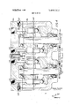
- FIG. 5 is an elevational view diagrammatically illustrating the application of the invention to another hydrostatic transmission having a single housing.
- FIG. 1 I have shown a hydrostatic machine having a shaft 1 which may serve as the input shaft of the hydrostatic pump and which is joumaled in a pair of axially spaced bearings 5 and 6 of a housing 3, 4 interconnected at 3a.
- the shaft 1 carries a cylinder drum 2 provided with a plurality of angularly equispaced axially extending cylinder bores 7, each slidably receiving a piston 8 shiftable into and out of the cylinder bore 7 parallel to its own axis and the axis of the shaft 1.
- Each of the pistons 8 is provided with a swivel head or ball 8a which is received swivelably within a shoe plate 9 of annular configuration, slidably bearing against a control disk 10 whose surface 10a is inclined at the angle a to the axis A of the shaft.
- Spring means may be provided to ensure that the pistons 8 and the shoe 9 seats firmly against the control surface 10a at all operating speeds of the rotary machine.
- the housing 3, 4 comprises a bell-shaped member 3 having a neck 3b in which the bearing 5 is received and which is formed with a lip-type seal capable of maintaining a subatmospheric pressure in a chamber 16 surrounding the cylinder barrel 2.
- the latter is provided with apertures 7a which open at a valve surface 2a bearing against the opposing surface of a valve or distributing plate 15 composed of low-friction material, e.g. bronze, seated against the plate 4.
- the plate 15 is provided with a pair of arcuate apertures 15a and 15b, respectively registering with several of the apertures 7 a as the barrel 2 rotates relative to the plate 15.
- arcuate apertures are disclosed in the aforementioned publication.
- Each of the apertures 15a and 15b registers, in turn, with a respective connecting passage 13 or 14 communicating, in turn, with the ports 11 and 12 to which suitable conduit means may be connected for joining the hydrostatic machine of FIG. 1 in a closed hydraulic circuit.
- a typical circuit is that illustrated in FIG. 3.
- port 11 forms the high-pressure side of the machine
- port 12 represents the low-pressure side and vice versa.
- the pressure at the low-pressure side may be maintained constant by a feed pump or pressure-regulation valve interconnecting the high and lowpressure sides.
- the low-pressure side preferably is held at about 6 to 8 atmospheres gauge.
- the same pressure is maintained by seal 23 within the housing.
- the interior 16 of the housing communicates via respective bores 17 and 18, formed directly in plate 4, with respective check valves 20 and compartments l9 and 21 operating, respectively, into the passages 13 and 14 mentioned earlier.
- the check valves 20 are poled, oriented and constructed to permit unidirectional flow of fluid from the housing into the low-pressure conduit or branch when a pressure differential in favor of such flow is established and to block reverse flow of fluid under any circumstances. Since reverse flow is blocked when the pressure difl'erentialfavors an outflow from the network into the chamber 16, whenever the operat- I ing high pressure is maintained in one of the networks, the corresponding check valve blocks flow therethrough and only the other check valve can operate, this only when the pressure within the housing exceeds the pressure within the low-pressure side as indicated.
- the shaft 1 may be coupled to a prime mover, e. g. an electric motor or an internal combustion engine for use of the machine as a pump, or may be connected to a load such as the driving wheels of an automotive vehicle having a hydrostatic transmission.
- a prime mover e. g. an electric motor or an internal combustion engine for use of the machine as a pump
- the barrel 2 is rotatably entrained by the shaft 1 while the pistons 8 ride with the shoe v9 along the control surface 10a which is inclined to the axis of rotation of the barrel as noted earlier.
- the pistons 8 are shifted between their fully extended position and a fully retracted position, they vary the size of the chamber 7 behind the piston and thereby draw fluid through one port and force it out through .the other in a repetitive intake/discharge cycle.
- hydraulic fluid is delivered by a hydrostatic pump at one port to drive the pistons outwardly as the barrel swings into registry with that port, the fluid then passing at low pressure into the discharge side for return to the pump.
- one of the ports 11 or 12 will be a high-pressure port while the other is the low-pressure port.
- FIG. 2 I show a hydrostatic machine according to the invention which is constituted as a pump and embodies many of the features already described in connection with FIG. 1.
- the shaft 101 extending out of the, housing portion 103 is connected with a drive means such as an inlet combustion engine or electric motor.
- the shaft 10l is provided with an extension. 25 beyond the bearing 106 running to a feed pump 26, the latter being bolted onto the housing portion 104 forming the fluid-distribution ports 111 and 112 as well as ducts 113 and 114 as previously described.
- the intake line 27 of the pump 26 is fed from a reservoir 28 while the pressure side of the pump26 is connected via line 29 to the using compartment 116 through the wall 103 thereof, preferably at the bottom of the wall.
- a return line 31 communicates with the compartment 1 16 at the upper side thereof via a fitting which is provided with a check valve 32 allowing unidirectional flowing from the housing to the reservoir 28.
- Valve 32 is provided with a strong spring 32a so that it simultaneously constitutes a pressure-regulating valve maintaining an adjustable pressure in the compartment 1 16 at about 6 to 8 atmospheres.
- the reservoir 28 can be open to the atmosphere and can constitute a heat exchanger or heat-dissipating cooler directly.
- the reservoir 28 may be closed to maintain a given pressure within the system and the cooler may be provided as a separate heat exchanger or radiator in a fluid circuit with the pump 1 26.
- the pump 26, consequently, circulates fresh fluid through the interior of the housing constantly with the advantages already set forth.
- the machine of FIG. 2 operates in the manner previously described in FIG. 1 when the barrel 102 is rotated by shaft 101 to shift the pistons 107 in the cylinder bores 108 of the closed hydraulic circuit and permit the check valve or 122 associated with the low-pressure side to connect the respective passage 113 or 114 with the interior of .the housing.
- the hydrostatic drive illustrated in FIG. 3 comprise in accordance with the usual practice, a hydrostatic pump whose shaft 201 is connected with an internal combustion engine and whose hydrostatic motor has its shaft 301 connected with a load.
- the shafts 201 and 301 are rotatably connected with the cylinder barrels 202, 302 whose pistons 208, 308 are axially shiftable, via inclined control surfaces not shown, within the cylinder bores 207, 307 to displace hydrostatic fluid along a closed path inter-connecting the, ports 211 and 311 via a line 33 and the ports 212, 312 via a line 34.
- the lines 33 and 34 may be relatively long when the pump and the motor are to be separated by some distance or can be eliminated when a single support block is provided in place of the separate fluid distribution plates 204, 304.
- a pressure-equalization reservoir 36 in which a compressed gas is maintained in the compartment 36a to form a yieldable cushion for the membrane 36b connected with line 35 and the chamber 216.
- a valve 360 serves to permit recharging of the accumulator. With expansion of the fluid within the transmission as a result of heating, there is a volume increase which is taken up by the accumulator 36 with compression of the gas cushion therein. Should there be a leak from the housing or an elastic yielding of the ducts from a housing and portions thereof, additional fluid is delivered by the accumulator. No separate feed pump is necessary.
- FIG. 4 I show a system wherein a housing 403, 404 is common to a pair of cylinder drums 402, with respective shafts 401 driven via gears 401a from a gear 40lb on the crankshaft 4010 of an automotive vehicle or like installation using a double pump aggregate. Since separate closed hydraulic networks may be provided with the low-pressure ports 412 at the same pressure and the high-pressure ports 411 at respective elevated pressures, a check valve 420 is provided to connect both ports 412 with the interior 416 of the BEST AVAILABLE COPY housing. The other check valves 422 for the high-pressure side are provided as previously described.
- FIG. shows a system wherein the cylinder drums 502 and 602 of the hydrostatic pump and hydrostatic motor are mounted in a common housing 503 and have input and output shafts 501 and 601 respectively connected to a source of rotary movement and a load.
- the control member 510 is here shown to be pivotal via lever 510' to adjust the displacement of the pump and a similar means may be provided for tilting the control plate 610.
- a single valve block 504 is here used with the intake side of the duct 514 connected with the check valve 520. Pressure within the system may be controlled by a regulating valve 650 connecting the high and low pressure lines or by a feed pump 526 driven by gearing 561 from the pump shaft 501.
- the major distinction between the system of FIG. 5 and that of FIG. 4 is the single housing for the barrels of both the pump and motor of this latter system.
- I also show a distributing valve 520a by which the check valve 520 and the duct associated pressure corresponding substantially to that of said low-pressure passage; and a duct wholly within said housing constituting the sole leakage-fluid path therefrom and connecting said low-pressure passage with said chamber, and a check valve in said duct for unidirectional flow of fluid between said chamber and said low-pressure passage and blocking reverse flow of therewith may be switched between the current lowpressure line 514 and the high-pressure line 513 when the hydraulic machines are reversed as described earlier. in this case only a single check valve need be used.
- the valve 520a may be coupled as represented by the dot-dash line 52% with lever 510 to effect automatically the change-over.
- a hydraulic system comprising a hydrostatic pump and a hydrostatic motor constituting hydrostatic machines; means connecting said machines in a closed fluid-circulating path and including a high-pressure passage and a low-pressure passage; a pressure-retentive housing surrounding at least one of said machines and-forming a chamber maintainable at an elevated fluid through said duct between said low-pressure passage and said chamber.
Landscapes
- Engineering & Computer Science (AREA)
- General Engineering & Computer Science (AREA)
- Mechanical Engineering (AREA)
- Control Of Fluid Gearings (AREA)
- Reciprocating Pumps (AREA)
- Hydraulic Motors (AREA)
Abstract
A hydrostatic machine, e.g. a hydrostatic pump or hydrostatic motor operating in a closed fluid circuit and having a housing into which leakage of the hydraulic medium can occur, is provided with check valves communicating between the housing and the main ports to enable leakage fluid to pass directly into the main hydraulic circuit.
Description
[ 51 Aug. 1, 1972 United States Patent Forster 3,143,859 8/1964 Thoma..... ...........60/52 US UX AAR fififi II 000 6 ..t 1 .r e wm wHM 588 666 99 9 H 938 256 243 826 079 333 m m Cuu EmMn N m m a CM G M n,
o m C m numb Aa me fiLW Rm a n D m Y w m HmA P M 7 Primary Examiner-Edgar W. Geoghegan Attorney-Karl F. Ross Appl. No.: 79,532
[22] Filed:
[57] ABSTRACT A hydrostatic machine, e.g. a hydrostatic pump or [30] Foreign Application Priority Data Oct. 10, 1969 Germany.............P 19 51 234.6 hydrostatic motor p i g a closed fluid circuit and having a housing into which leakage of the hydraulic medium can occur, is provided with check [52] US. Cl. ..............60/53 A, 60/52 US, 60/DIG. 5,
60/51 51 Int. Cl. 39/02, Fl6h 39/10 f mmumcatmg heme? d [58] Field of Search.....60/53 A, 52 US, DIG. 5, 53 R mam P0rts to enable leakage mud to P duectly the main hydraulic circuit.
9 Claim, 5 Drawing Figures References Cited UNITED STATES PATENTS 2,597,050 5/1952 Audemar...................60/51UX EP'A'TENTEDms' 1 m2 sum 1 0F 4 Franz Forsfer 1 VENTOR FIG.
PATE'NTEDAIIB- I 1912 3.680.312
t(@::f) %fiii:::/
II/ Y Franz Forsfer f 1 INVENTOR. 504 520a 513 I FIG. 5
Attom e y saw u or 4 Franz F0 rsfer INVENTOR.
A (Ross Attorney 1 HYDROSTATIC MACHINE FIELD OF THE INVENTION My present invention relates to hydraulic machines and, more particularly, to hydrostatic machines operating in a closed fluid circuit.
BACKGROUND OF THE INVENTION Hydrostatic machines, e.g. hydrostatic pumps and motors, generally are provided with a closed circuit and a pair of main ports connected with a hydraulic load and serving as discharge or intake ports, depending upon the sense of operation of the machine. Among the important hydrostatic machines of this class are the socalled axial-piston pumps and axial-piston motors which serve, respectively, to displace the hydrostatic fluid under the drive of a power source, e.g. an intemalcombustion engine or an electric motor and/or may be driven by hydraulic fluid pressure to operate, in turn, a mechanical member such as the output shaft. Axialpiston devices and the principles involved therein are described in FLUID POWER, US. Government Printing Office, 1966, at pages 109-112 and pages 199 and following, respectively.
For the most part, an axial-piston pump may comprise a rotary cylinder barrel provided with a plurality of angularly equispaced cylinder bores successively communicating with a pair of kidney-shaped fluid-distribution apertures on a fluid-distribution surface against which the cylinder barrel is held under axial pressure. The pistons within the cylinders are reciprocated by virtue of rotation of the barrel and the fact that the pistons bear upon a control surface which is inclined to the axes of rotation of the barrel so that during about half of each rotation the pistons are urged inwardly while the pistons are able to move outwardly during the remainder of each rotation.
Inward displacement of the pistons, of course, corresponds to a reduction in the volume of the chamber behind the piston to expel fluid in the form of a hydraulic medium through one kidney-shaped aperture while outward movement of the piston expands the chamber to draw the hydraulic medium into the cylinder bore from the other kidney-shaped aperture. The kidneyshaped apertures, of course, are connected to the discharge and intake ports of the hydraulic machine, respectively, depending upon the angle and direction of tilt of the control surface, the displacement of the pump and the function of the main port (as high-pressure or low-pressure port) can be established. The pump shaft may be connected to the control surface to drive the latter and may also be coupled with the barrel via means as described, for example, in the commonly assigned copending application Ser. No. 68,254 filed Aug. 31, 70 by Walter HEYL. A hydrostatic motor operating in accordance with the same principles, will generally comprise a cylinder barrel having a surface perpendicular to its axis of rotation abuting a fluid-distribution surface whose arcuate apertures communicate with the individual cylinder bores opening at this surface. The pistons may bear against an inclined control surface and are coupled with an output shaft via the latter so that fluid entering through one of the apertures forces the piston successively outwardly to drive the barrel and, consequently, rotate the shaft. Inclination of the control surface in this case, determines the speed of the shaft and the torque delivered to any load which may be coupled therewith.
It is not uncommon to interconnect the discharge port of the pump with the intake side of the motor and the outlet side of the motor with the intake side of the pump by suitable conduits and thereby create a hydrostatic drive or transmission in which the transmission ratio between the input shaft of the pump and the output shaft of the motor is established by the inclination of the barrel axes of the hydrostatic machines to the axis of the respective shaft. Such transmissions may be wholly contained in a common housing or may be mounted remote from one another so that they can be connected by relatively longlines. One advantage of the hydrostatic transmission is precisely the possibility of providing the hydrostatic pump in the vicinity of a prime mover or other energy source, while the hydrostatic motors are mounted directly adjacent the load driven thereby. Transmissions of this nature have been found to be particularly suitable in vehicular applications wherein the prime mover is an internal-combustion engine and the load is the vehicle wheel. Of course, a number of hydrostatic motors can be connected to a single pump or a number of pumps may be provided to service a single hydrostatic motor. In general, however, it is found to be advantageous to provide each hydrostatic pump with a hydrostatic motor in a closed fluid path.
It should be understood. that the term closed fluid path is intended herein to refer to a system in which the pump is connected directly to the load, i.e. each of the conduits communicating with the ports of the pump run to the corresponding ports of the motor. While one of the conduits may be operated as a high-pressure transmission line while the other conduit is at low pressure, the hydrostatic machines are generally reversible to interchange the functions of these lines. Furthermore, both machines may be provided in a closed housing so that the entire transmission network and fluid supply is contained within this housing from which only the input and output shafts emerge. In closed circulating paths of the character described, it is necessary to hold the low-pressure side at a predetermined pressure level and an auxiliary pump and/or a pressure-regulating valve may be used to this end.
It will be appreciated that effective operation of the axial-piston pump or axial-piston motor is accompanied and in fact may require some leakage of the hydraulic medium from the system, e. g. at the fluid-distribution surfaces of a valve plate and the rotating cylinder drum, respectively. When a closed circulating path was required, it has been necessary in some priorart devices to provide a further conduit between the pump and load to convey the leakage fluid from one hydrostatic machine to the other. This is, of course, a significant disadvantage when the pump is greatly removed from the motor and when complex mechanisms are interposed between them. In an excavating machine, for example, the hydrostatic pump may be mounted upon a chassis carrying a turntable which, in turn, is provided with the excavating scoops and like devices. When the turntable is used, it rotates relatively to the chassis. Hence hydrostatic motors carried by the turntable must be connected through a rotating seal with the hydrostatic pump and the need for an additional conduit between the hydrostatic motor and the hydrostatic pump complicates such systems to a further extent. It will be appreciated that conduits for the indicated purposes must be capable of withstanding pressure and the use of an additional conduit involves increasing complexities because of the associated seals.
In open hydraulic circuits, moreover, i.e. those using a collecting reservoir into which fluid flows in a pressureless state, it is common to connect the leakagefluid conduit to the reservoir so that the fluid returns to the power cycle, the leakage path being pressureless. It is also known to provide, in such systems (open fluidcirculating path), pumps which are disposed'directly in the reservoir and leakage can occur directly into the reservoir. These systems make use of a relatively large housing for the pump and possible pressurization of the fluid therein to prevent cavitation at the inlet side of the pump. In all cases, however, techniques which have been found to be satisfactory for handling the leakage fluid of the open hydraulic circuit, i.e. those using fluid reservoirs, have not been found to be practical or satisfactory in closed fluid circuits while the need for added leakage-fluid conduits renders earlier closed systems expensive and complex.
OBJECTS OF THE INVENTION It is the principal object of the present invention to provide an improved hydrostatic machine arrangement of the closed-circulation type wherein the aforementioneddisadvantages are obviated.
Another object of my invention is to provide an improved hydrostatic'machine, e.g. axial-piston pump or axial-piston motor, in which the handling of leakage fluids is simplified, which is of lower cost and simpler operation than earlier systems, and which can be used for arrangements such as excavators in which two hydraulic machines are interconnected but separated by means creating sealing difficulties.
SUMMARY OF THE INVENTION The above and other objects of the invention, which will become apparent hereinafter, are attained in a hydraulic machine which comprises a housing, preferably closely surrounding the axial-piston barrel which is connected directly with the low-pressure port of the machine, i.e. the intake port of a hydrostatic pump or the discharge port of a hydrostatic motor, via a check valve designed to permit unidirectional flow of the hydraulic medium from the housing surrounding the barrel into the low-pressure port. The housing sealingly closes the hydrostatic machine and, when the ports of the machine are functionally interchangeable, both of them may be connected with the housing chamber by respective check valves, only the check valve communicating with the low-pressure port being open to permit the pressure differential thereacross to feed the leakage fluid into the low-pressure side. The
high-pressure side, of course, maintains its check valve low-pressure side of the hydrostatic machine, a check valve connecting the interior of the housing with the low-pressure duct, conduit or port, and a hydrostatic machine disposed within this housing and having a leakage path opening from the machine into the housing whereby the leakage medium can traverse the check valve into the low-pressure ducts. A separate leakage-fluid collector is thereby eliminated, the system does not require a separate line between the pump and motor for conducting the leakage fluid and compensating for leakage losses, and only two ducts need bridge the hydrostatic pump and motor. Furthermore, the cooling of the hydrostatic machine is improved by virtue of the fact that there is a continuous circulation of the leakage medium from the machine into the space surrounding the machine and enclosed by the housing, and from the housing into the low-pressure side of the machine.
The present invention is applicable to hydrostatic pumps and motors, the intake of the fonner being the low-pressure side whereas the discharge of the latter is at low pressure. However invention can also apply to more than one hydrostatic machine in a single housing, i.e. a double-pump assembly in which two hydrostatic pumps are provided within a single housing, two hydrostatic drives including a pump and one or more motors, the housing in each case being generally closed. However, it has beenfound that increasing the size of the housing to accommodate more than one hydrostatic machine opens the door to difficulties with respect to maintaining the seal of the housing and it is therefore preferred to provide a housing for each machine which closely surrounds the axial-piston drum thereof. It should be noted that one not only achieves a saving in the cost of a leakage-fluid duct when the present invention is used, but also reduces the complexities of the pump and motor structures themselves since fittings, ports, chambers and like structure associated with the leakage ducts are eliminated as well. It is possible by such simplification of the overall structure to eliminate the tendency of the machine to leak and thereby reduce maintenance and surveillance.
The reduction of the leakage losses from the main closed hydraulic circuit into the housing surrounding the hydrostatic machine is a consequence in part of the high back pressure maintained in the sealed housing and, therefore, prevalent at the outlet side of the leakage path. As a result, no feed pump need be used to compensate for leakage loss in a great many cases and, wherever a feed ptunp is required in a system under the present invention, it may be dimensioned to have a smaller capacity and energy consumption than the feed pumps which have been used heretofore with similar hydraulic machines operating, for example, in closed circuits with pressurelesshousings or the like.
When no feed pump is required, I have found it to be advantageous to provide, at one or more locations along the closed hydraulic path, equalization reservoirs or hydropneumatic accumulators adapted to deliver,
while maintaining the pressure in the housing, fluid to the latter to compensate for the leakage losses from the main hydraulic circuit. Such accumulators may be of the type described at pages 86 89 of FLUID POWER. cited earlier. The accumulator, which is maintained at the predetermined pressure within the sealed housing,
compensates for changes in the volume of fluid available in themain circulating path as a result of thermal expansion and contraction of the fluid and the conduits containingv same, elastic yieldability of the conduit walls, etc.
When ahydropneumatic accumulator is employed, I have found it advantageous after a period determined by experience, e.g. a thousand operating hours, to charge the accumulator and restore the pressure therein. Of course, the accumulator should only be provided. at the low-pressure sideof the, closed circulation pathand, when the. hydraulic machine is reversible so that the ports alternate in function between high-pressure. andilow-pressure ports, reversing-valve means is used in accordance. with the invention to connect the low-pressure side, with the accumulator at all times. Two such accumulators may, of course, be provided and connectedwith thesides of the hydraulic network by cutoff valve means so that the accumulator currently at the high-pressure. side is blocked .while the other accumulator is rendered effective. Furthermore, when a pair of interconnected hydrostatic machines are employed, the. accumulator can communicate directly with the interior'of one of the machine housings or the common housing of both machines to maintain the pressure in the low-pressure side of the network substantially constant-indirectly.
When a feed pump is provided, i.e. when the hydrostatic machine is provided with a pump designed to deliver the-hydraulic medium to the closed fluid path to compensatefor leakage losses, a secondary circulation is established between the housing chamber of one machine preferably the motor and the low-pressure line thereof. A cooling system can be provided in the latter case at the discharge side of the feed pump. The cooler may be a conventional radiator built onto the housing of the apparatus or other conventional heat-dissipating device. Hence the interior of the housing is constantly rinsed with fresh cool hydraulic medium and the machine is able to operate with increasing efficiency.
Accordingto still another feature of this invention, the hydrostatic machine forms part of a hydraulic transmission driven by an internal-combustion engine and the working fluid of the hydrostatic drive is also the lubricant for the. internal combustion engine. The feed pump and cooling pump can thereby constitute the means for maintaining the predetermined pressure within the housing, the means for cooling the latter, and the means for lubricating the engine.
DESCRIPTION OF THE DRAWING The above and other objects, features and advantages -of the present invention will become more readily apparent from the following description, reference being made to the accompanying drawing in which:
FIG. 1 is an axial cross-sectional view through an embodiment of a hydrostatic machine according to the invention; FIG. 2 is a side-elevational view, partly in axial section and partly in diagrammatic form, illustrating another embodiment of the invention wherein the hydrostatic machine employs a feed pump;
FIG. 3 is a view similar to FIG. 2 of a hydrostatic transmission according to the invention;
FIG. 4 is a view similar to FIG. 1 illustrating how the invention is applied to a double-pump assembly; and
FIG. 5 is an elevational view diagrammatically illustrating the application of the invention to another hydrostatic transmission having a single housing.
SPECIFIC DESCRIPTION In FIG. 1 I have shown a hydrostatic machine having a shaft 1 which may serve as the input shaft of the hydrostatic pump and which is joumaled in a pair of axially spaced bearings 5 and 6 of a housing 3, 4 interconnected at 3a. The shaft 1 carries a cylinder drum 2 provided with a plurality of angularly equispaced axially extending cylinder bores 7, each slidably receiving a piston 8 shiftable into and out of the cylinder bore 7 parallel to its own axis and the axis of the shaft 1. Each of the pistons 8 is provided with a swivel head or ball 8a which is received swivelably within a shoe plate 9 of annular configuration, slidably bearing against a control disk 10 whose surface 10a is inclined at the angle a to the axis A of the shaft. Spring means (not shown) may be provided to ensure that the pistons 8 and the shoe 9 seats firmly against the control surface 10a at all operating speeds of the rotary machine.
The housing 3, 4 comprises a bell-shaped member 3 having a neck 3b in which the bearing 5 is received and which is formed with a lip-type seal capable of maintaining a subatmospheric pressure in a chamber 16 surrounding the cylinder barrel 2. The latter is provided with apertures 7a which open at a valve surface 2a bearing against the opposing surface of a valve or distributing plate 15 composed of low-friction material, e.g. bronze, seated against the plate 4. The plate 15 is provided with a pair of arcuate apertures 15a and 15b, respectively registering with several of the apertures 7 a as the barrel 2 rotates relative to the plate 15. Such arcuate apertures are disclosed in the aforementioned publication. Each of the apertures 15a and 15b registers, in turn, with a respective connecting passage 13 or 14 communicating, in turn, with the ports 11 and 12 to which suitable conduit means may be connected for joining the hydrostatic machine of FIG. 1 in a closed hydraulic circuit. A typical circuit is that illustrated in FIG. 3. When port 11 forms the high-pressure side of the machine, port 12 represents the low-pressure side and vice versa. The pressure at the low-pressure side may be maintained constant by a feed pump or pressure-regulation valve interconnecting the high and lowpressure sides. The low-pressure side preferably is held at about 6 to 8 atmospheres gauge. The same pressure is maintained by seal 23 within the housing. When the system is a hydrostatic motor, the discharge is at this pressure while, when the machine is a hydrostatic pump, the supply or intake is at this pressure.
The interior 16 of the housing communicates via respective bores 17 and 18, formed directly in plate 4, with respective check valves 20 and compartments l9 and 21 operating, respectively, into the passages 13 and 14 mentioned earlier. The check valves 20 are poled, oriented and constructed to permit unidirectional flow of fluid from the housing into the low-pressure conduit or branch when a pressure differential in favor of such flow is established and to block reverse flow of fluid under any circumstances. Since reverse flow is blocked when the pressure difl'erentialfavors an outflow from the network into the chamber 16, whenever the operat- I ing high pressure is maintained in one of the networks, the corresponding check valve blocks flow therethrough and only the other check valve can operate, this only when the pressure within the housing exceeds the pressure within the low-pressure side as indicated.
The shaft 1 may be coupled to a prime mover, e. g. an electric motor or an internal combustion engine for use of the machine as a pump, or may be connected to a load such as the driving wheels of an automotive vehicle having a hydrostatic transmission. In the mode of operation of the machine as a pump, the barrel 2 is rotatably entrained by the shaft 1 while the pistons 8 ride with the shoe v9 along the control surface 10a which is inclined to the axis of rotation of the barrel as noted earlier. As the pistons 8 are shifted between their fully extended position and a fully retracted position, they vary the size of the chamber 7 behind the piston and thereby draw fluid through one port and force it out through .the other in a repetitive intake/discharge cycle. When the machine is operated as a motor, hydraulic fluid is delivered by a hydrostatic pump at one port to drive the pistons outwardly as the barrel swings into registry with that port, the fluid then passing at low pressure into the discharge side for return to the pump. In either case, one of the ports 11 or 12 will be a high-pressure port while the other is the low-pressure port.
When port 11 is under high pressure and port 12 is under low pressure, the fluid in line 13 is likewise at an elevated pressure to bias the check valve 19 into a closed position. Fluid from the chamber 16 cannot enter the closed hydraulic network via line ,17. However, the normal pressure in the housing chamber 16 is 6 to 8 atmospheres (gauge) and sufflces, when thepressure drops at the low-pressure duct 14 and port 12, to bleed the leakage fluid from the chamber 16 into the hydraulic line 14 for return to the main circulating path. The fluid within the chamber 16 in part derives from leakage at the control surfaces 2a. When the control surface 10a is adjusted to vary the functions of the ports or the sense of rotation is altered, only the check valve associated with the low-pressure side will be operative. The high-pressure check valve will invariably be closed.
In FIG. 2, I show a hydrostatic machine according to the invention which is constituted as a pump and embodies many of the features already described in connection with FIG. 1. In this embodiment, the shaft 101, extending out of the, housing portion 103 is connected with a drive means such as an inlet combustion engine or electric motor. The shaft 10l is provided with an extension. 25 beyond the bearing 106 running to a feed pump 26, the latter being bolted onto the housing portion 104 forming the fluid- distribution ports 111 and 112 as well as ducts 113 and 114 as previously described.
The intake line 27 of the pump 26 is fed from a reservoir 28 while the pressure side of the pump26 is connected via line 29 to the using compartment 116 through the wall 103 thereof, preferably at the bottom of the wall. A return line 31 communicates with the compartment 1 16 at the upper side thereof via a fitting which is provided with a check valve 32 allowing unidirectional flowing from the housing to the reservoir 28. Valve 32 is provided with a strong spring 32a so that it simultaneously constitutes a pressure-regulating valve maintaining an adjustable pressure in the compartment 1 16 at about 6 to 8 atmospheres. In thiscase, the reservoir 28 can be open to the atmosphere and can constitute a heat exchanger or heat-dissipating cooler directly. As an alternative, the reservoir 28 may be closed to maintain a given pressure within the system and the cooler may be provided as a separate heat exchanger or radiator in a fluid circuit with the pump 1 26. The pump 26, consequently, circulates fresh fluid through the interior of the housing constantly with the advantages already set forth. In general, the machine of FIG. 2 operates in the manner previously described in FIG. 1 when the barrel 102 is rotated by shaft 101 to shift the pistons 107 in the cylinder bores 108 of the closed hydraulic circuit and permit the check valve or 122 associated with the low-pressure side to connect the respective passage 113 or 114 with the interior of .the housing.
The hydrostatic drive illustrated in FIG. 3 comprise in accordance with the usual practice, a hydrostatic pump whose shaft 201 is connected with an internal combustion engine and whose hydrostatic motor has its shaft 301 connected with a load. The shafts 201 and 301 are rotatably connected with the cylinder barrels 202, 302 whose pistons 208, 308 are axially shiftable, via inclined control surfaces not shown, within the cylinder bores 207, 307 to displace hydrostatic fluid along a closed path inter-connecting the, ports 211 and 311 via a line 33 and the ports 212, 312 via a line 34. It will be appreciated that the lines 33 and 34 may be relatively long when the pump and the motor are to be separated by some distance or can be eliminated when a single support block is provided in place of the separate fluid distribution plates 204, 304. The
remainder of the system, including the fluid- distribution antifriction plates 215, 315 the ports 217 and 317 connected to the low-pressure side of the network and the check valves 220, 320 and222, 322 is, of course, identical with the corresponding parts of the system of FIG. 1. In addition, a pressure-equalization reservoir 36, in which a compressed gas is maintained in the compartment 36a to form a yieldable cushion for the membrane 36b connected with line 35 and the chamber 216. A valve 360 serves to permit recharging of the accumulator. With expansion of the fluid within the transmission as a result of heating, there is a volume increase which is taken up by the accumulator 36 with compression of the gas cushion therein. Should there be a leak from the housing or an elastic yielding of the ducts from a housing and portions thereof, additional fluid is delivered by the accumulator. No separate feed pump is necessary.
In FIG. 4, I show a system wherein a housing 403, 404 is common to a pair of cylinder drums 402, with respective shafts 401 driven via gears 401a from a gear 40lb on the crankshaft 4010 of an automotive vehicle or like installation using a double pump aggregate. Since separate closed hydraulic networks may be provided with the low-pressure ports 412 at the same pressure and the high-pressure ports 411 at respective elevated pressures, a check valve 420 is provided to connect both ports 412 with the interior 416 of the BEST AVAILABLE COPY housing. The other check valves 422 for the high-pressure side are provided as previously described.
FIG. shows a system wherein the cylinder drums 502 and 602 of the hydrostatic pump and hydrostatic motor are mounted in a common housing 503 and have input and output shafts 501 and 601 respectively connected to a source of rotary movement and a load. The control member 510 is here shown to be pivotal via lever 510' to adjust the displacement of the pump and a similar means may be provided for tilting the control plate 610. A single valve block 504 is here used with the intake side of the duct 514 connected with the check valve 520. Pressure within the system may be controlled by a regulating valve 650 connecting the high and low pressure lines or by a feed pump 526 driven by gearing 561 from the pump shaft 501. The major distinction between the system of FIG. 5 and that of FIG. 4 is the single housing for the barrels of both the pump and motor of this latter system.
In FIG. 5, I also show a distributing valve 520a by which the check valve 520 and the duct associated pressure corresponding substantially to that of said low-pressure passage; and a duct wholly within said housing constituting the sole leakage-fluid path therefrom and connecting said low-pressure passage with said chamber, and a check valve in said duct for unidirectional flow of fluid between said chamber and said low-pressure passage and blocking reverse flow of therewith may be switched between the current lowpressure line 514 and the high-pressure line 513 when the hydraulic machines are reversed as described earlier. in this case only a single check valve need be used. The valve 520a may be coupled as represented by the dot-dash line 52% with lever 510 to effect automatically the change-over.
I claim:
1. A hydraulic system comprising a hydrostatic pump and a hydrostatic motor constituting hydrostatic machines; means connecting said machines in a closed fluid-circulating path and including a high-pressure passage and a low-pressure passage; a pressure-retentive housing surrounding at least one of said machines and-forming a chamber maintainable at an elevated fluid through said duct between said low-pressure passage and said chamber.
2. The hydraulic system defined in. claim 1 wherein a respective duct connects each of said passages with said chamber and is provided with a respective check valvepermitting unidirectional flow of fluid from the chamber into said passages.
3. The hydraulic system defined in claim 1, further comprising distributing valve means for selectively connecting said duct with one of said passages.
4. The hydraulic system defined in claim 1, further comprising a feed pump connected with said chamber for circulating fluid therethrough.
5. The hydraulic system defined in claim 4, further comprising a heat-dissipating cooler in a hydraulic circuit with said feed pump.
6. The hydraulic system defined in claim 1 wherein both said machines are provided within said housing.
s l l h in fi "fl 1% hyil i ulic system defined in claim 1, further comprising means for maintaining the pressure within said chamber at a level of substantially 6 to 8 atmospheres gauge.
9. The hydraulic system defined in claim 1 wherein said housing encloses a pair of hydrostatic pumps, coupled together in a double-pump aggregate.
Claims (9)
1. A hydraulic system comprising a hydrostatic pump and a hydrostatic motor constituting hydrostatic machines; means connecting said machines in a closed fluid-circulating path and including a high-pressure passage and a low-pressure passage; a pressure-retentive housing surrounding at least one of said machines and forming a chamber maintainable at an elevated pressure corresponding substantially to that of said low-pressure passage; and a duct wholly within said housing constituting the sole leakage-fluid path therefrom and connecting said lowpressure passage with said chamber, and a check valve in said duct for unidirectional flow of fluid between said chamber and said low-pressure passage and blocking reverse flow of fluid through said duct between said low-pressure passage and said chamber.
2. The hydraulic system defined in claim 1 wherein a respective duct connects each of said passages with said chamber and is provided with a respective check valve permitting unidirectional flow of fluid from the chamber into said passages.
3. The hydraulic system defined in claim 1, further comprising distributing valve means for selectively connecting said duct with one of said passages.
4. The hydraulic system defined in claim 1, further comprising a feed pump connected with said chamber for circulating fluid therethrough.
5. The hydraulic system defined in claim 4, further comprising a heat-dissipating cooler in a hydraulic circuit with said feed pump.
6. The hydraulic system defined in claim 1 wherein both said machines are provided within said housing.
7. The hydraulic system defined in claim 1, further comprising a hydropneumatic accumulator connected to said chamber for maintaining a predetermined pressure level therein.
8. The hydraulic system defined in claim 1, further comprising means for maintaining the pressure within said chamber at a level of substantially 6 to 8 atmospheres gauge.
9. The hydraulic system defined in claim 1 wherein said housing encloses a pair of hydrostatic pumps, coupled together in a double-pump aggregate.
Applications Claiming Priority (1)
| Application Number | Priority Date | Filing Date | Title |
|---|---|---|---|
| DE1951234A DE1951234B2 (en) | 1969-10-10 | 1969-10-10 | Axial piston machine for a hydrostatic remote transmission |
Publications (1)
| Publication Number | Publication Date |
|---|---|
| US3680312A true US3680312A (en) | 1972-08-01 |
Family
ID=5747900
Family Applications (1)
| Application Number | Title | Priority Date | Filing Date |
|---|---|---|---|
| US79532A Expired - Lifetime US3680312A (en) | 1969-10-10 | 1970-10-09 | Hydrostatic machine |
Country Status (7)
| Country | Link |
|---|---|
| US (1) | US3680312A (en) |
| JP (1) | JPS5024722B1 (en) |
| DE (1) | DE1951234B2 (en) |
| ES (1) | ES384380A1 (en) |
| FR (1) | FR2071729A5 (en) |
| GB (1) | GB1320242A (en) |
| SE (1) | SE378284B (en) |
Cited By (31)
| Publication number | Priority date | Publication date | Assignee | Title |
|---|---|---|---|---|
| US4821936A (en) * | 1987-09-21 | 1989-04-18 | Mobil Oil Corporation | Hydraulic index drive system |
| US4987796A (en) * | 1989-06-12 | 1991-01-29 | Tecumseh Products Company | Internal reservoir-defining body for permitting oil expansion within a hydrostatic transmission housing |
| US5001901A (en) * | 1988-10-04 | 1991-03-26 | Sundstrand Corporation | Hydraulic fluid circuit for full case hydraulic unit |
| US5094078A (en) * | 1989-07-28 | 1992-03-10 | Honda Giken Kogyo Kabushiki Kaisha | Hydraulic transmission for motor vehicle |
| US5146748A (en) * | 1988-02-03 | 1992-09-15 | Kanzaki Kokyukoki Mfg. Co., Ltd. | Axle driving apparatus |
| US5235810A (en) * | 1992-09-28 | 1993-08-17 | Tecumseh Products Company | Conduit valve providing wide neutral in a hydrostatic transmission |
| US5419130A (en) * | 1991-08-28 | 1995-05-30 | Hydromatik Gmbh | Hydrostatic machine with drain oil discharge |
| US5440878A (en) * | 1992-08-27 | 1995-08-15 | Vernon E. Gleasman | Variable hydraulic machine |
| US5473964A (en) * | 1988-02-03 | 1995-12-12 | Kanzaki Kokyukoki Mfg. Co., Ltd. | Axle driving apparatus |
| WO1998011345A1 (en) * | 1996-09-13 | 1998-03-19 | Franz Xaver Meiller Fahrzeug- und Maschinenfabrik - GmbH & Co. KG | Hydraulic pump and hydraulic engine |
| US5782142A (en) * | 1996-04-12 | 1998-07-21 | Tuff Torq Corporation | Axle driving apparatus |
| US6443263B1 (en) * | 1999-09-05 | 2002-09-03 | Honda Giken Kogyo Kabushiki Kaisha | Oil tank for an internal combustion engine |
| US6491118B1 (en) * | 2000-11-20 | 2002-12-10 | Deere & Company | Hydrostatic system with charge flow monitoring |
| US6672843B1 (en) | 2002-04-08 | 2004-01-06 | Hydro-Gear Limited Partnership | Dual pump apparatus comprising dual drive shafts and auxiliary pump |
| EP1378662A1 (en) * | 2002-07-05 | 2004-01-07 | Bieri Hydraulik Ag | Hydraulic axial piston pump |
| US20040226294A1 (en) * | 2003-03-31 | 2004-11-18 | Honda Motor Co., Ltd. | Hydraulic continuously variable transmission |
| US6889595B1 (en) * | 1999-07-16 | 2005-05-10 | Hydro-Gear Limited Partnership | Pump |
| US6938718B1 (en) | 1988-02-03 | 2005-09-06 | Kanzaki Kokyukoki Mfg. Co., Ltd. | Axle driving apparatus |
| US20050217919A1 (en) * | 1988-02-03 | 2005-10-06 | Hiedeaki Okada | Axle driving apparatus |
| US6953327B1 (en) | 2003-03-11 | 2005-10-11 | Hydro-Gear Limited Partnership | Dual pump |
| US7082762B1 (en) | 1999-07-16 | 2006-08-01 | Hydro-Gear Limited Partnership | Pump |
| US20060272326A1 (en) * | 1999-10-18 | 2006-12-07 | Ryota Ohashi | Pump Unit |
| US7178336B1 (en) | 1999-07-16 | 2007-02-20 | Hydro-Gear Limited Partnership | Pump |
| US20070144169A1 (en) * | 1999-10-18 | 2007-06-28 | Ryota Ohashi | Pump Unit |
| US7263829B1 (en) * | 1999-07-16 | 2007-09-04 | Hydro-Gear Limited Partnership | Pump |
| US20080202113A1 (en) * | 1999-10-18 | 2008-08-28 | Ryota Ohashi | Tandem Pump Unit |
| US7516615B1 (en) | 1999-07-16 | 2009-04-14 | Hydro-Gear Limited Partnership | Pump |
| US20090250941A1 (en) * | 2008-04-02 | 2009-10-08 | Gilbert Jr Ed | System and method of increasing the output energy of an electrical motor by transferring the output energy through a plurality of hydraulic networks to create a continuous electrical cycle |
| US20110138803A1 (en) * | 2008-04-02 | 2011-06-16 | Gilbert Jr Ed | System of Transferring and Storing Energy and Method of Use Thereof |
| CN106471249A (en) * | 2014-07-07 | 2017-03-01 | Kyb株式会社 | Hydraulic rotating machine tool |
| CN114787509A (en) * | 2019-12-17 | 2022-07-22 | 米司创有限责任公司 | Axial piston pump with inclined plates |
Families Citing this family (10)
| Publication number | Priority date | Publication date | Assignee | Title |
|---|---|---|---|---|
| JPS504602A (en) * | 1973-05-16 | 1975-01-18 | ||
| JPH0721316B2 (en) * | 1986-12-09 | 1995-03-08 | 本田技研工業株式会社 | Hydraulic transmission |
| DD257860A1 (en) * | 1987-02-25 | 1988-06-29 | Karl Marx Stadt Ind Werke | HYDROSTATIC PISTON MACHINE WITH OIL RINSE |
| DE19859442C1 (en) * | 1998-12-22 | 2000-10-26 | Brueninghaus Hydromatik Gmbh | Hydrostatic piston machine |
| FI107075B (en) * | 2000-02-28 | 2001-05-31 | Ideachip Oy Insinoeoeritoimist | Return arrangement for the leakage oil of a hydraulic motor |
| CN107246365A (en) * | 2017-05-22 | 2017-10-13 | 江苏昊科汽车空调有限公司 | A kind of vehicle-mounted air conditioner compressor spinning piston component |
| DE102019113536B4 (en) | 2019-05-21 | 2022-04-21 | Danfoss A/S | Device for providing connections to a machine section of a hydraulic machine arrangement |
| IT201900024241A1 (en) * | 2019-12-17 | 2021-06-17 | Mixtron S R L | AXIAL PISTON PUMP WITH INCLINED PLATE |
| CN113431757B (en) * | 2021-06-25 | 2022-02-22 | 江苏可奈力机械制造有限公司 | High-efficiency high-speed microminiature hydraulic pump |
| DE102021209515A1 (en) | 2021-08-31 | 2023-03-02 | Robert Bosch Gesellschaft mit beschränkter Haftung | Hydrostatic axial piston machine with a cooling circuit and servo-hydraulic actuator with a hydrostatic axial piston machine and with a cooling circuit |
Citations (5)
| Publication number | Priority date | Publication date | Assignee | Title |
|---|---|---|---|---|
| US2597050A (en) * | 1942-06-25 | 1952-05-20 | Olaer Marine | Hydraulic transmission for reproducing mechanical motions at remote points |
| US3143859A (en) * | 1962-03-07 | 1964-08-11 | Dowty Hydraulic Units Ltd | Hydraulic apparatus |
| US3208222A (en) * | 1963-07-18 | 1965-09-28 | Atlas Industriewagen G M B H | Battery operated industrial truck |
| US3372545A (en) * | 1965-02-10 | 1968-03-12 | Dowty Technical Dev Ltd | Hydraulic apparatus |
| US3396536A (en) * | 1966-08-08 | 1968-08-13 | Cessna Aircraft Co | Hydraulic transmission |
-
1969
- 1969-10-10 DE DE1951234A patent/DE1951234B2/en active Pending
-
1970
- 1970-09-30 FR FR7035412A patent/FR2071729A5/fr not_active Expired
- 1970-10-09 SE SE7013734A patent/SE378284B/xx unknown
- 1970-10-09 GB GB4803670A patent/GB1320242A/en not_active Expired
- 1970-10-09 US US79532A patent/US3680312A/en not_active Expired - Lifetime
- 1970-10-09 ES ES384380A patent/ES384380A1/en not_active Expired
- 1970-10-12 JP JP45089610A patent/JPS5024722B1/ja active Pending
Patent Citations (5)
| Publication number | Priority date | Publication date | Assignee | Title |
|---|---|---|---|---|
| US2597050A (en) * | 1942-06-25 | 1952-05-20 | Olaer Marine | Hydraulic transmission for reproducing mechanical motions at remote points |
| US3143859A (en) * | 1962-03-07 | 1964-08-11 | Dowty Hydraulic Units Ltd | Hydraulic apparatus |
| US3208222A (en) * | 1963-07-18 | 1965-09-28 | Atlas Industriewagen G M B H | Battery operated industrial truck |
| US3372545A (en) * | 1965-02-10 | 1968-03-12 | Dowty Technical Dev Ltd | Hydraulic apparatus |
| US3396536A (en) * | 1966-08-08 | 1968-08-13 | Cessna Aircraft Co | Hydraulic transmission |
Cited By (52)
| Publication number | Priority date | Publication date | Assignee | Title |
|---|---|---|---|---|
| US4821936A (en) * | 1987-09-21 | 1989-04-18 | Mobil Oil Corporation | Hydraulic index drive system |
| US20050217919A1 (en) * | 1988-02-03 | 2005-10-06 | Hiedeaki Okada | Axle driving apparatus |
| US5752417A (en) * | 1988-02-03 | 1998-05-19 | Kanzaki Kokyukoki Mfg. Co. Ltd. | Axle driving apparatus |
| US6938718B1 (en) | 1988-02-03 | 2005-09-06 | Kanzaki Kokyukoki Mfg. Co., Ltd. | Axle driving apparatus |
| US5146748A (en) * | 1988-02-03 | 1992-09-15 | Kanzaki Kokyukoki Mfg. Co., Ltd. | Axle driving apparatus |
| US5950500A (en) * | 1988-02-03 | 1999-09-14 | Kanzaki Kokyukoki Mfg. Co., Ltd. | Axle driving apparatus |
| US5694816A (en) * | 1988-02-03 | 1997-12-09 | Kanzaki Kokyukoki Mfg. Co., Ltd. | Axle driving apparatus |
| US5664465A (en) * | 1988-02-03 | 1997-09-09 | Kanzaki Kokyukoki Mfg. Co., Ltd. | Axle driving apparatus |
| US5655417A (en) * | 1988-02-03 | 1997-08-12 | Kanzaki Kokyukoki Mfg. Co. Ltd. | Axle driving apparatus |
| US5473964A (en) * | 1988-02-03 | 1995-12-12 | Kanzaki Kokyukoki Mfg. Co., Ltd. | Axle driving apparatus |
| US5598748A (en) * | 1988-02-03 | 1997-02-04 | Kanzaki Kokyukoki Mfg. Co., Ltd. | Axle driving apparatus |
| US5636555A (en) * | 1988-02-03 | 1997-06-10 | Kanzaki Kokyukoki Mfg. Co. Ltd. | Axle driving apparatus |
| US5647249A (en) * | 1988-02-03 | 1997-07-15 | Kanzaki Kokyukoki Mfg. Co. Ltd. | Axle driving apparatus |
| US5001901A (en) * | 1988-10-04 | 1991-03-26 | Sundstrand Corporation | Hydraulic fluid circuit for full case hydraulic unit |
| US4987796A (en) * | 1989-06-12 | 1991-01-29 | Tecumseh Products Company | Internal reservoir-defining body for permitting oil expansion within a hydrostatic transmission housing |
| EP0410819B1 (en) * | 1989-07-28 | 1995-02-15 | Honda Giken Kogyo Kabushiki Kaisha | Hydraulic transmission for motor vehicles |
| US5094078A (en) * | 1989-07-28 | 1992-03-10 | Honda Giken Kogyo Kabushiki Kaisha | Hydraulic transmission for motor vehicle |
| US5419130A (en) * | 1991-08-28 | 1995-05-30 | Hydromatik Gmbh | Hydrostatic machine with drain oil discharge |
| US5440878A (en) * | 1992-08-27 | 1995-08-15 | Vernon E. Gleasman | Variable hydraulic machine |
| US5235810A (en) * | 1992-09-28 | 1993-08-17 | Tecumseh Products Company | Conduit valve providing wide neutral in a hydrostatic transmission |
| US5782142A (en) * | 1996-04-12 | 1998-07-21 | Tuff Torq Corporation | Axle driving apparatus |
| WO1998011345A1 (en) * | 1996-09-13 | 1998-03-19 | Franz Xaver Meiller Fahrzeug- und Maschinenfabrik - GmbH & Co. KG | Hydraulic pump and hydraulic engine |
| US7263829B1 (en) * | 1999-07-16 | 2007-09-04 | Hydro-Gear Limited Partnership | Pump |
| US7516615B1 (en) | 1999-07-16 | 2009-04-14 | Hydro-Gear Limited Partnership | Pump |
| US7178336B1 (en) | 1999-07-16 | 2007-02-20 | Hydro-Gear Limited Partnership | Pump |
| US7082762B1 (en) | 1999-07-16 | 2006-08-01 | Hydro-Gear Limited Partnership | Pump |
| US6889595B1 (en) * | 1999-07-16 | 2005-05-10 | Hydro-Gear Limited Partnership | Pump |
| US6443263B1 (en) * | 1999-09-05 | 2002-09-03 | Honda Giken Kogyo Kabushiki Kaisha | Oil tank for an internal combustion engine |
| US20080289326A1 (en) * | 1999-10-18 | 2008-11-27 | Ryota Ohashi | Pump Unit |
| US7409829B2 (en) * | 1999-10-18 | 2008-08-12 | Kanzaki Kokyukoki Mfg. Co., Ltd. | Pump unit |
| US7677038B2 (en) | 1999-10-18 | 2010-03-16 | Kanzaki Kokyukoki Mfg. Co., Ltd. | Pump unit |
| US20060272326A1 (en) * | 1999-10-18 | 2006-12-07 | Ryota Ohashi | Pump Unit |
| US20070006581A1 (en) * | 1999-10-18 | 2007-01-11 | Ryota Ohashi | Pump Unit |
| US7788919B2 (en) | 1999-10-18 | 2010-09-07 | Kanzaki Kokyukoki Mfg. Co., Ltd. | Pump unit |
| US7418819B2 (en) * | 1999-10-18 | 2008-09-02 | Kanzaki Kokyukoki Mfg. Co., Ltd | Pump unit |
| US20070144169A1 (en) * | 1999-10-18 | 2007-06-28 | Ryota Ohashi | Pump Unit |
| US20080202113A1 (en) * | 1999-10-18 | 2008-08-28 | Ryota Ohashi | Tandem Pump Unit |
| US6491118B1 (en) * | 2000-11-20 | 2002-12-10 | Deere & Company | Hydrostatic system with charge flow monitoring |
| US7320577B1 (en) | 2002-04-08 | 2008-01-22 | Hydro-Gear Limited Partnership | Dual pump transmission |
| US6672843B1 (en) | 2002-04-08 | 2004-01-06 | Hydro-Gear Limited Partnership | Dual pump apparatus comprising dual drive shafts and auxiliary pump |
| US7566207B1 (en) | 2002-04-08 | 2009-07-28 | Hydro-Gear Limited Partnership | Dual pump transmission |
| EP1378662A1 (en) * | 2002-07-05 | 2004-01-07 | Bieri Hydraulik Ag | Hydraulic axial piston pump |
| US6953327B1 (en) | 2003-03-11 | 2005-10-11 | Hydro-Gear Limited Partnership | Dual pump |
| US7229256B1 (en) | 2003-03-11 | 2007-06-12 | Hydro-Gear Limited Partnership | Dual pump transmission |
| US7806667B1 (en) | 2003-03-11 | 2010-10-05 | Hydro-Gear Limited Partnership | Dual pump |
| US8272315B1 (en) | 2003-03-11 | 2012-09-25 | Hydro-Gear Limited Partnership | Dual pump |
| US7000388B2 (en) * | 2003-03-31 | 2006-02-21 | Honda Motor Co., Ltd. | Hydraulic continuously variable transmission |
| US20040226294A1 (en) * | 2003-03-31 | 2004-11-18 | Honda Motor Co., Ltd. | Hydraulic continuously variable transmission |
| US20090250941A1 (en) * | 2008-04-02 | 2009-10-08 | Gilbert Jr Ed | System and method of increasing the output energy of an electrical motor by transferring the output energy through a plurality of hydraulic networks to create a continuous electrical cycle |
| US20110138803A1 (en) * | 2008-04-02 | 2011-06-16 | Gilbert Jr Ed | System of Transferring and Storing Energy and Method of Use Thereof |
| CN106471249A (en) * | 2014-07-07 | 2017-03-01 | Kyb株式会社 | Hydraulic rotating machine tool |
| CN114787509A (en) * | 2019-12-17 | 2022-07-22 | 米司创有限责任公司 | Axial piston pump with inclined plates |
Also Published As
| Publication number | Publication date |
|---|---|
| DE1951234B2 (en) | 1974-07-11 |
| JPS5024722B1 (en) | 1975-08-18 |
| GB1320242A (en) | 1973-06-13 |
| ES384380A1 (en) | 1973-05-01 |
| DE1951234A1 (en) | 1971-04-22 |
| FR2071729A5 (en) | 1971-09-17 |
| SE378284B (en) | 1975-08-25 |
Similar Documents
| Publication | Publication Date | Title |
|---|---|---|
| US3680312A (en) | Hydrostatic machine | |
| US3036434A (en) | Thrust bearings for hydrostatic transmissions | |
| US3641765A (en) | Hydrostatic vehicle transmission | |
| US4529362A (en) | Servo pump for hydraulic systems | |
| US3486335A (en) | Common valve plate hydrostatic transmission | |
| US2907230A (en) | Hydrostatic power transmissions and brakes | |
| US3131539A (en) | Hydraulic transmission | |
| US5072587A (en) | Hydraulically operated continuously variable transmission | |
| US3396536A (en) | Hydraulic transmission | |
| EP0736152B1 (en) | Continuously variable hydrostatic transmission | |
| KR970703504A (en) | CONTINUOUSLY VARIABLE HYDROSTATIC TRANSMISSION | |
| US4843818A (en) | Rotary hydrostatic machines or transmissions | |
| US3272279A (en) | Fluid pressure operated drive and clutch systems | |
| US3143858A (en) | Hydrostatic transmission | |
| US4794756A (en) | Hydraulic differential | |
| US4939900A (en) | Hydraulically operated continuously variable transmission | |
| US2975597A (en) | Hydraulic transmission | |
| US3465616A (en) | Vehicle drive | |
| US3823650A (en) | Destroking of hydrostatic drive motors | |
| US7146810B1 (en) | Pump assembly | |
| US3827239A (en) | Hydraulic power transmission and braking system for vehicles | |
| US3177665A (en) | Hydrostatic transmission | |
| US3465520A (en) | Hydrostatic transmission | |
| US3949824A (en) | Drive arrangements for mechanical handling vehicles | |
| US4922717A (en) | Hydraulically operated continuously variable transmission |