US3416198A - Retaining and locking device - Google Patents
Retaining and locking device Download PDFInfo
- Publication number
- US3416198A US3416198A US613886A US61388667A US3416198A US 3416198 A US3416198 A US 3416198A US 613886 A US613886 A US 613886A US 61388667 A US61388667 A US 61388667A US 3416198 A US3416198 A US 3416198A
- Authority
- US
- United States
- Prior art keywords
- head member
- strap
- body portion
- assembly
- retaining
- Prior art date
- Legal status (The legal status is an assumption and is not a legal conclusion. Google has not performed a legal analysis and makes no representation as to the accuracy of the status listed.)
- Expired - Lifetime
Links
Images

Classifications
-
- B—PERFORMING OPERATIONS; TRANSPORTING
- B65—CONVEYING; PACKING; STORING; HANDLING THIN OR FILAMENTARY MATERIAL
- B65D—CONTAINERS FOR STORAGE OR TRANSPORT OF ARTICLES OR MATERIALS, e.g. BAGS, BARRELS, BOTTLES, BOXES, CANS, CARTONS, CRATES, DRUMS, JARS, TANKS, HOPPERS, FORWARDING CONTAINERS; ACCESSORIES, CLOSURES, OR FITTINGS THEREFOR; PACKAGING ELEMENTS; PACKAGES
- B65D63/00—Flexible elongated elements, e.g. straps, for bundling or supporting articles
- B65D63/10—Non-metallic straps, tapes, or bands; Filamentary elements, e.g. strings, threads or wires; Joints between ends thereof
- B65D63/1018—Joints produced by application of integral securing members, e.g. buckles, wedges, tongue and slot, locking head and teeth or the like
- B65D63/1027—Joints produced by application of integral securing members, e.g. buckles, wedges, tongue and slot, locking head and teeth or the like the integral securing member being formed as a female and male locking member, e.g. locking head and locking teeth, or the like
- B65D63/1036—Joints produced by application of integral securing members, e.g. buckles, wedges, tongue and slot, locking head and teeth or the like the integral securing member being formed as a female and male locking member, e.g. locking head and locking teeth, or the like the female locking member being provided with at least one metal barb
-
- Y—GENERAL TAGGING OF NEW TECHNOLOGICAL DEVELOPMENTS; GENERAL TAGGING OF CROSS-SECTIONAL TECHNOLOGIES SPANNING OVER SEVERAL SECTIONS OF THE IPC; TECHNICAL SUBJECTS COVERED BY FORMER USPC CROSS-REFERENCE ART COLLECTIONS [XRACs] AND DIGESTS
- Y10—TECHNICAL SUBJECTS COVERED BY FORMER USPC
- Y10T—TECHNICAL SUBJECTS COVERED BY FORMER US CLASSIFICATION
- Y10T24/00—Buckles, buttons, clasps, etc.
- Y10T24/14—Bale and package ties, hose clamps
- Y10T24/1498—Plastic band
-
- Y—GENERAL TAGGING OF NEW TECHNOLOGICAL DEVELOPMENTS; GENERAL TAGGING OF CROSS-SECTIONAL TECHNOLOGIES SPANNING OVER SEVERAL SECTIONS OF THE IPC; TECHNICAL SUBJECTS COVERED BY FORMER USPC CROSS-REFERENCE ART COLLECTIONS [XRACs] AND DIGESTS
- Y10—TECHNICAL SUBJECTS COVERED BY FORMER USPC
- Y10T—TECHNICAL SUBJECTS COVERED BY FORMER US CLASSIFICATION
- Y10T24/00—Buckles, buttons, clasps, etc.
- Y10T24/42—Independent, headed, aperture pass-through fastener
Definitions
- a retaining and locking device having an elongated strap body portion to be passed through an assembly of items, a base portion formed at one end thereof to abut the assembly and prevent excess insertion, and a locking head movable on the projecting end of the strap body portion, and against the assembly, with means for locking the head on the strap body portion against the assembly, thus saving time and cost in retaining the assembly and eliminating the need for use of 360 wrapping devices such as have been conventionally used.
- This invention relates to a retaining and locking device of novel construction, and operation, which is versatile in use and adapted to enclose and hold items without the necessity of 360 wrapping, as in conventional practice, and without risk of damage to the retained assembly, and which is automatically adjustable to the width of the assembly.
- the device of this invention may be made at low cost and readily applied to the articles to be assembled without damaging or marring their surfaces, to efficiently and rapidly secure them in retained and locked position.
- a typical example thereof is for retaining an assembly of hubbed disks such as are used in testing jet engines.
- the device of the invention eliminates the deficiencies of prior devices, serving efiiciently over a wide range of items to be assembled; it may be readily applied to and removed from the articles to be assembled without any risk of damage to their surfaces.
- the device incorporates a self locking head and an elongated strap body portion in connection therewith.
- said head may be formed unitarily with said body portion and detachably connected thereto by a neck portion and separated therefrom by twisting or other procedure, which may be readily and simply performed.
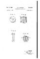
- FIG. 1 is a top plan view of a retaining and locking device embodying my invention
- FIG. 2 is a side elevational view thereof
- FIG. 3 is a longitudinal sectional view thereof, taken at line 33 of FIG. 1,
- FIG. 4 is a top plan, partly broken view of a form thereof, shown in FIG. 6,
- FIG. 5 is a fragmentary side, elevational, partly fragmentary view thereof
- FIG. 6 is a longitudinal, sectional view taken at line 6-6 of FIG. 4,
- FIG. 7 is a top plan view of an assembly of items, showing a retaining locking device of my invention applied thereto,
- FIG. 8 is a side elevational view thereof
- FIG. 9 is a fragmentary, side elevational view of an assembly of items having a device of the invention applied thereto.
- FIG. 10 is a fragmentary elevational, partly sectional view of items held together by a device of the invention.
- the retaining and locking device 10 (FIG. 1) of the invention may be made of relatively inexpensive plastic or other material, molded or otherwise formed to define an elongated strap body portion 11 having opposite spaced ends 12, 14, said body portion being adapted to be passed through (FIGS. 8 and 10) an assembly 17 of items and to extend at one end (15) therebeyond.
- the end 12 of the body portion has 'a base 16 formed thereon preferably disposed at an angle to the longitudinal axis of body portion The device is inserted through the assembly of items Y to be retained and locked, being inserted, for example, through apertures or openings or interstices in said items,
- the base 16 serving as a stop preventing excess insertion.
- a head member 20 which may (FIG. 3) be generally tapered or circular as at 21 (FIGS. 4 to 6) is provided for reception of the body member end 22 therethrough and for sliding and locking movement on the body portion A and against the assembly of articles, to retain and lock them.
- Said head member may be formed unitarily with the body portion as, for example, being separably connected thereto by a neck 22 or other means enabling ready separation, as by snapping or twisting the head member.
- the head member may be separately formed as above noted or may be connected with or formed unitarily with the body portion 11 and readily stripped or torn therefrom.
- the head 21 is then slid along the extending end 15 (FIG. 8) of the strap and into abutment with the assembly of articles.
- Means are provided in the head member, pursuant to this invention, for complementary axial sliding movement on the strap in yieldable automatic intercugagement of the head and body portion and the retained article assembly.
- an opening or slot 23 (FIG. 3) is provided through the head member 20 for reception therethrough of strap body portion 11; a latch member 24, such as a barb or flexible plate, is secured to the head member and projects preferably angularly into the slot 23 (FIG. 6) so that, as the head member is moved along the strap in one direction (toward the article assembly) the plate 24 yields until the head member is moved to final position against the assembly (FIGS. 8 and 10). Plate 24 resists accidental disengagement of the parts. Plate 24 may be a metal or other barb, insert or otherwise molded with or secured to the head member.
- a second slot 25 may be provided (FIG. 1) intersecting the slot 23 (through which the strap passes) at an angle, to permit the strap to be twisted and locked in the plane of slot 25,
- An initially integral device for retaining and locking said device comprising an elongated strap body portion having opposite, spaced ends, and proportioned to be positioned in the assembly and to extend, at one end, therebeyond,
- stop means on the opposite end of the body portion to abut the assembly to prevent excess insertion of the device therein
- a head member connected to the strap body portion by suitable means so as to be readily severable therefrom for use therewith,
- said means to abut the assembly to prevent excess insertion of the device in the assembly comprising an angularly formed base on the opposite end of said body portion.
- said means to so abut the assembly to prevent excess insertion of the device in the assembly comprising a base formed on the opposite end of said body portion and extending beyond the cross sectional configuration of the body portion.
- said means on said head member for said complementary reception of the strap comprising an opening provided in said head member and means in said head member so engaging said so extending end of the strap body portion comprising friction means in said head member engaging said body portion.
- said means in said head member so engaging said so extending end of 40 the strap comprising a slot provided in said head member to receive said strap therethrough, and
- said means in said head member so engaging said strap comprising a slot provided in the head member to receive said extending end of the strap therethrough, and
- said means in said head member so engaging said strap comprising means in said head member to receive said extending end of the strap therethrough, in one plane, and for locking the strap therein, in another plane.
- said means in said head member so engaging said so extending end of the strap comprising multi-planar openings in said head member to enable the strap to be received in the head member and twisted and locked therein.
Landscapes
- Engineering & Computer Science (AREA)
- Mechanical Engineering (AREA)
- Buckles (AREA)
Description
Dec. 17, 1968 G. H. GEISINGER 3,
RETAINING AND LOCKING DEVICE Filed Feb. 5. 1967 2 Sheets-Sheet 1 FIG. I
K i i {w I .ml
FIG. 2 l0 F" I G. 6
w INVENTOR G. H. GE/S/NGER Dec. 17, 1968 5. H. GEISINGER 3,
RETAINING AND LOCKING DEVICE Filed Feb. 5, 1967 2 Sheets-Sheet 2 1 INVENTOR G. H. GE/S/NGER BY M fiEORNEY United States Patent 3,416,198 RETAINING AND LOCKING DEVICE George H. Geisinger, Elizabeth, N.J., assignor to The Thomas & Betts Co. Inc., Elizabeth, N.J., a corporation of New Jersey Filed Feb. 3, 1967, Ser. No. 613,886 9 Claims. (Cl. 24-150) ABSTRACT OF THE DISCLOSURE A retaining and locking device having an elongated strap body portion to be passed through an assembly of items, a base portion formed at one end thereof to abut the assembly and prevent excess insertion, and a locking head movable on the projecting end of the strap body portion, and against the assembly, with means for locking the head on the strap body portion against the assembly, thus saving time and cost in retaining the assembly and eliminating the need for use of 360 wrapping devices such as have been conventionally used.
This invention relates to a retaining and locking device of novel construction, and operation, which is versatile in use and adapted to enclose and hold items without the necessity of 360 wrapping, as in conventional practice, and without risk of damage to the retained assembly, and which is automatically adjustable to the width of the assembly.
The device of this invention may be made at low cost and readily applied to the articles to be assembled without damaging or marring their surfaces, to efficiently and rapidly secure them in retained and locked position.
It may be used for retaining and locking an infinite variety of articles of various kinds, contours and proportions. A typical example thereof (without limitation thereto) is for retaining an assembly of hubbed disks such as are used in testing jet engines. Pursuant to prior practices, weighted blades were secured to the disks by use of rivets and other metal devices. Problems encountered in con nection with such prior devices are the high cost thereof; in insertion and removal of the pieces often the surface of the disk is scratched; the marks must be rubbed out by hand. It is necesary to maintain inventories, different metal devices being required for various disks.
The device of the invention eliminates the deficiencies of prior devices, serving efiiciently over a wide range of items to be assembled; it may be readily applied to and removed from the articles to be assembled without any risk of damage to their surfaces.
The device incorporates a self locking head and an elongated strap body portion in connection therewith. In one form of the invention said head may be formed unitarily with said body portion and detachably connected thereto by a neck portion and separated therefrom by twisting or other procedure, which may be readily and simply performed.
The drawings, illustrating procedures and devices useful in carrying out the invention, and the description below, are exemplary only of the invention, which shall be deemed to cover all other devices and procedures coming within the scope and purview of the appended claims.
In the drawings, wherein similar reference characters indicate like parts:
FIG. 1 is a top plan view of a retaining and locking device embodying my invention,
FIG. 2 is a side elevational view thereof,
FIG. 3 is a longitudinal sectional view thereof, taken at line 33 of FIG. 1,
FIG. 4 is a top plan, partly broken view of a form thereof, shown in FIG. 6,
3,416,198 Patented Dec. 17, 1968 FIG. 5 is a fragmentary side, elevational, partly fragmentary view thereof,
FIG. 6 is a longitudinal, sectional view taken at line 6-6 of FIG. 4,
FIG. 7 is a top plan view of an assembly of items, showing a retaining locking device of my invention applied thereto,
FIG. 8 is a side elevational view thereof,
FIG. 9 is a fragmentary, side elevational view of an assembly of items having a device of the invention applied thereto, and
FIG. 10 is a fragmentary elevational, partly sectional view of items held together by a device of the invention.
The retaining and locking device 10 (FIG. 1) of the invention may be made of relatively inexpensive plastic or other material, molded or otherwise formed to define an elongated strap body portion 11 having opposite spaced ends 12, 14, said body portion being adapted to be passed through (FIGS. 8 and 10) an assembly 17 of items and to extend at one end (15) therebeyond. The end 12 of the body portion has 'a base 16 formed thereon preferably disposed at an angle to the longitudinal axis of body portion The device is inserted through the assembly of items Y to be retained and locked, being inserted, for example, through apertures or openings or interstices in said items,
the base 16 serving as a stop preventing excess insertion.
A head member 20, which may (FIG. 3) be generally tapered or circular as at 21 (FIGS. 4 to 6) is provided for reception of the body member end 22 therethrough and for sliding and locking movement on the body portion A and against the assembly of articles, to retain and lock them. Said head member may be formed unitarily with the body portion as, for example, being separably connected thereto by a neck 22 or other means enabling ready separation, as by snapping or twisting the head member. a
The head member may be separately formed as above noted or may be connected with or formed unitarily with the body portion 11 and readily stripped or torn therefrom. The head 21 is then slid along the extending end 15 (FIG. 8) of the strap and into abutment with the assembly of articles. Means are provided in the head member, pursuant to this invention, for complementary axial sliding movement on the strap in yieldable automatic intercugagement of the head and body portion and the retained article assembly.
To this end, an opening or slot 23 (FIG. 3) is provided through the head member 20 for reception therethrough of strap body portion 11; a latch member 24, such as a barb or flexible plate, is secured to the head member and projects preferably angularly into the slot 23 (FIG. 6) so that, as the head member is moved along the strap in one direction (toward the article assembly) the plate 24 yields until the head member is moved to final position against the assembly (FIGS. 8 and 10). Plate 24 resists accidental disengagement of the parts. Plate 24 may be a metal or other barb, insert or otherwise molded with or secured to the head member. A second slot 25 may be provided (FIG. 1) intersecting the slot 23 (through which the strap passes) at an angle, to permit the strap to be twisted and locked in the plane of slot 25,
if desired. I claim:
1. An initially integral device for retaining and locking said device comprising an elongated strap body portion having opposite, spaced ends, and proportioned to be positioned in the assembly and to extend, at one end, therebeyond,
stop means on the opposite end of the body portion to abut the assembly to prevent excess insertion of the device therein,
a head member connected to the strap body portion by suitable means so as to be readily severable therefrom for use therewith,
means on said head member for complementary sliding reception of the strap in the head member,
and means on said head member engaging said so extending end of the strap body portion [yieldably] on movement of the head member thereon, said suitable connecting means, forming when severed, a tapered free end on said so extending end to facilitate use thereof.
2. In a device as set forth in claim 1, said means on said head member so engaging said so extending end of the strap body portion yieldably and in locking relation on movement of the head member thereon.
3. In a device as set forth in claim 1, said means to abut the assembly to prevent excess insertion of the device in the assembly comprising an angularly formed base on the opposite end of said body portion.
4. In a device as set forth in claim 1, said means to so abut the assembly to prevent excess insertion of the device in the assembly, comprising a base formed on the opposite end of said body portion and extending beyond the cross sectional configuration of the body portion.
5. In a device as set forth in claim 1, said means on said head member for said complementary reception of the strap comprising an opening provided in said head member and means in said head member so engaging said so extending end of the strap body portion comprising friction means in said head member engaging said body portion.
6. In a device as set forth in claim 1, said means in said head member so engaging said so extending end of 40 the strap comprising a slot provided in said head member to receive said strap therethrough, and
means in said head member extending into said slot,
frictionally engaging said strap.
7. In a device as set forth in claim 1, said means in said head member so engaging said strap comprising a slot provided in the head member to receive said extending end of the strap therethrough, and
means in said head member angularly extending into said slot, frictionally engaging said strap.
8. In a device as set forth in claim 1,
said means in said head member so engaging said strap comprising means in said head member to receive said extending end of the strap therethrough, in one plane, and for locking the strap therein, in another plane.
9. In a device as set forth in claim 1,
said means in said head member so engaging said so extending end of the strap comprising multi-planar openings in said head member to enable the strap to be received in the head member and twisted and locked therein.
References Cited UNITED STATES PATENTS 988,090 3/1911 Hamilton 24-153 2,514,939 7/1950 Crary 24-153 1,830,950 11/1931 Lake 292-322 2,025,960 12/1935 Sindler 24-208.3 3,009,220 11/1961 Fein 2430.5 3,186,047 6/1965 Schwester et a1 24-16 3,022,557 2/1962 Logan 248-74 FOREIGN PATENTS 530,904 8/ 1954 Netherlands.
DONALD A. GRIFFIN, Primary Examiner.
11.5. C1. X.R.
Priority Applications (1)
| Application Number | Priority Date | Filing Date | Title |
|---|---|---|---|
| US613886A US3416198A (en) | 1967-02-03 | 1967-02-03 | Retaining and locking device |
Applications Claiming Priority (1)
| Application Number | Priority Date | Filing Date | Title |
|---|---|---|---|
| US613886A US3416198A (en) | 1967-02-03 | 1967-02-03 | Retaining and locking device |
Publications (1)
| Publication Number | Publication Date |
|---|---|
| US3416198A true US3416198A (en) | 1968-12-17 |
Family
ID=24459063
Family Applications (1)
| Application Number | Title | Priority Date | Filing Date |
|---|---|---|---|
| US613886A Expired - Lifetime US3416198A (en) | 1967-02-03 | 1967-02-03 | Retaining and locking device |
Country Status (1)
| Country | Link |
|---|---|
| US (1) | US3416198A (en) |
Cited By (15)
| Publication number | Priority date | Publication date | Assignee | Title |
|---|---|---|---|---|
| US3525128A (en) * | 1968-11-20 | 1970-08-25 | Laszlo Hidassy | Bundling strap |
| US4214349A (en) * | 1978-11-30 | 1980-07-29 | Midland-Ross Corporation | Tie wrap |
| US4379538A (en) * | 1980-12-03 | 1983-04-12 | Welles Theodore W | Article supporting device |
| US5344107A (en) * | 1993-09-23 | 1994-09-06 | Hall Surgical | Tubing strap |
| WO1995006601A1 (en) * | 1993-08-31 | 1995-03-09 | Panduit Corp. | Low thread force cable tie |
| US5440786A (en) * | 1993-06-04 | 1995-08-15 | Sorensen; Soren C. | Injection molding of cable ties with a mold having an enhanced core section |
| US5621949A (en) * | 1995-04-07 | 1997-04-22 | Thomas & Betts Corproation | Barbed cable tie |
| USD418168S (en) * | 1997-04-01 | 1999-12-28 | Critchley Electrical Products Pty Ltd | Tag |
| US20040139575A1 (en) * | 2003-01-17 | 2004-07-22 | Kargilis John S. | Vehicle bumper and method of attachment |
| US7520030B2 (en) | 2005-08-08 | 2009-04-21 | Thomas & Betts International, Inc. | Cable tie having detachable tail |
| US20100071169A1 (en) * | 2008-09-22 | 2010-03-25 | Mark Kent Williams | Twist off tamper-proof fastener |
| US9334091B2 (en) | 2010-10-11 | 2016-05-10 | Ideal Industries, Inc. | Cable lacing tie devices and methods of using the same |
| US9555943B2 (en) | 2010-10-11 | 2017-01-31 | Ideal Industries, Inc. | Cable lacing tie devices and methods of using the same |
| US9682806B2 (en) | 2014-03-24 | 2017-06-20 | Ideal Industries, Inc. | Cable lacing tie devices and methods of using the same |
| US9751670B2 (en) | 2015-09-09 | 2017-09-05 | F. Balwyker Investments, LLC | Twist off cable tie fastener |
Citations (7)
| Publication number | Priority date | Publication date | Assignee | Title |
|---|---|---|---|---|
| US988090A (en) * | 1909-01-18 | 1911-03-28 | John Raymond Hamilton | Strap and fastener. |
| US1830950A (en) * | 1929-08-02 | 1931-11-10 | Preferred Utilities Mfg Corp | Safety seal |
| US2025960A (en) * | 1935-07-09 | 1935-12-31 | Jay J Sindler | Retainer device |
| US2514939A (en) * | 1946-03-19 | 1950-07-11 | Jay D Crary | Paper fastener |
| US3009220A (en) * | 1958-02-24 | 1961-11-21 | Westinghouse Electric Corp | Flexible tieing and locking device |
| US3022557A (en) * | 1958-06-24 | 1962-02-27 | Thomas & Betts Corp | Cable bundling and supporting strap |
| US3186047A (en) * | 1962-08-14 | 1965-06-01 | Thomas & Betts Corp | Self clinching bundling strap |
-
1967
- 1967-02-03 US US613886A patent/US3416198A/en not_active Expired - Lifetime
Patent Citations (7)
| Publication number | Priority date | Publication date | Assignee | Title |
|---|---|---|---|---|
| US988090A (en) * | 1909-01-18 | 1911-03-28 | John Raymond Hamilton | Strap and fastener. |
| US1830950A (en) * | 1929-08-02 | 1931-11-10 | Preferred Utilities Mfg Corp | Safety seal |
| US2025960A (en) * | 1935-07-09 | 1935-12-31 | Jay J Sindler | Retainer device |
| US2514939A (en) * | 1946-03-19 | 1950-07-11 | Jay D Crary | Paper fastener |
| US3009220A (en) * | 1958-02-24 | 1961-11-21 | Westinghouse Electric Corp | Flexible tieing and locking device |
| US3022557A (en) * | 1958-06-24 | 1962-02-27 | Thomas & Betts Corp | Cable bundling and supporting strap |
| US3186047A (en) * | 1962-08-14 | 1965-06-01 | Thomas & Betts Corp | Self clinching bundling strap |
Cited By (19)
| Publication number | Priority date | Publication date | Assignee | Title |
|---|---|---|---|---|
| US3525128A (en) * | 1968-11-20 | 1970-08-25 | Laszlo Hidassy | Bundling strap |
| US4214349A (en) * | 1978-11-30 | 1980-07-29 | Midland-Ross Corporation | Tie wrap |
| US4379538A (en) * | 1980-12-03 | 1983-04-12 | Welles Theodore W | Article supporting device |
| US5440786A (en) * | 1993-06-04 | 1995-08-15 | Sorensen; Soren C. | Injection molding of cable ties with a mold having an enhanced core section |
| US5593630A (en) * | 1993-06-04 | 1997-01-14 | Gb Electrical, Inc. | Method of injection molding of cable ties with a mold having an enhanced core section |
| WO1995006601A1 (en) * | 1993-08-31 | 1995-03-09 | Panduit Corp. | Low thread force cable tie |
| US5517727A (en) * | 1993-08-31 | 1996-05-21 | Panduit Corp. | Low thread force cable tie |
| US5344107A (en) * | 1993-09-23 | 1994-09-06 | Hall Surgical | Tubing strap |
| US5621949A (en) * | 1995-04-07 | 1997-04-22 | Thomas & Betts Corproation | Barbed cable tie |
| USD418168S (en) * | 1997-04-01 | 1999-12-28 | Critchley Electrical Products Pty Ltd | Tag |
| US20040139575A1 (en) * | 2003-01-17 | 2004-07-22 | Kargilis John S. | Vehicle bumper and method of attachment |
| US7520030B2 (en) | 2005-08-08 | 2009-04-21 | Thomas & Betts International, Inc. | Cable tie having detachable tail |
| US7866006B2 (en) | 2005-08-08 | 2011-01-11 | Thomas & Betts International, Inc. | Cable tie having detachable tail |
| US20100071169A1 (en) * | 2008-09-22 | 2010-03-25 | Mark Kent Williams | Twist off tamper-proof fastener |
| US7934297B2 (en) | 2008-09-22 | 2011-05-03 | Mark Kent Williams | Twist off tamper-proof fastener |
| US9334091B2 (en) | 2010-10-11 | 2016-05-10 | Ideal Industries, Inc. | Cable lacing tie devices and methods of using the same |
| US9555943B2 (en) | 2010-10-11 | 2017-01-31 | Ideal Industries, Inc. | Cable lacing tie devices and methods of using the same |
| US9682806B2 (en) | 2014-03-24 | 2017-06-20 | Ideal Industries, Inc. | Cable lacing tie devices and methods of using the same |
| US9751670B2 (en) | 2015-09-09 | 2017-09-05 | F. Balwyker Investments, LLC | Twist off cable tie fastener |
Similar Documents
| Publication | Publication Date | Title |
|---|---|---|
| US3416198A (en) | Retaining and locking device | |
| US4380101A (en) | Tie hook, particularly rubber spring hook | |
| US4450961A (en) | Display bracket for socket drive units and package employing same | |
| US3402435A (en) | Tag attaching or bundle fastening device | |
| US2844244A (en) | Molded plastic container for drills and the like | |
| US3486200A (en) | Cable strap | |
| US4275485A (en) | Sealing devices | |
| US2292310A (en) | Clamping band | |
| US4149329A (en) | Reversible and foldable tag | |
| US3384938A (en) | Pliable material clamp | |
| US3516124A (en) | Connector for holding articles together | |
| US4170299A (en) | Rack and tie-back clip assembly | |
| US2366147A (en) | Typewriter reel | |
| US2768458A (en) | Baggage tag | |
| US2947047A (en) | Paper clip | |
| US3881334A (en) | Storage ring with integral closure | |
| US4036358A (en) | Clear view coin wrap | |
| US3349446A (en) | Box flap holder | |
| US1984589A (en) | Tag | |
| US2746457A (en) | Universal follow up compressor | |
| KR830003334A (en) | Automatic folding handles made of plastic | |
| US1304417A (en) | Indicating-tag | |
| ES8302225A1 (en) | Locking pin with a head and annular retaining means. | |
| US1601572A (en) | Spoon holder | |
| US1766801A (en) | Key case |