US3336666A - Insulation cutting tool - Google Patents
Insulation cutting tool Download PDFInfo
- Publication number
- US3336666A US3336666A US476326A US47632665A US3336666A US 3336666 A US3336666 A US 3336666A US 476326 A US476326 A US 476326A US 47632665 A US47632665 A US 47632665A US 3336666 A US3336666 A US 3336666A
- Authority
- US
- United States
- Prior art keywords
- wire
- stripping
- jacket
- blades
- tool
- Prior art date
- Legal status (The legal status is an assumption and is not a legal conclusion. Google has not performed a legal analysis and makes no representation as to the accuracy of the status listed.)
- Expired - Lifetime
Links
Images


Classifications
-
- H—ELECTRICITY
- H02—GENERATION; CONVERSION OR DISTRIBUTION OF ELECTRIC POWER
- H02G—INSTALLATION OF ELECTRIC CABLES OR LINES, OR OF COMBINED OPTICAL AND ELECTRIC CABLES OR LINES
- H02G1/00—Methods or apparatus specially adapted for installing, maintaining, repairing or dismantling electric cables or lines
- H02G1/12—Methods or apparatus specially adapted for installing, maintaining, repairing or dismantling electric cables or lines for removing insulation or armouring from cables, e.g. from the end thereof
- H02G1/1202—Methods or apparatus specially adapted for installing, maintaining, repairing or dismantling electric cables or lines for removing insulation or armouring from cables, e.g. from the end thereof by cutting and withdrawing insulation
- H02G1/1204—Hand-held tools
- H02G1/1207—Hand-held tools the cutting element not rotating about the wire or cable
- H02G1/1209—Hand-held tools the cutting element not rotating about the wire or cable making a transverse cut
- H02G1/1212—Hand-held tools the cutting element not rotating about the wire or cable making a transverse cut using wire or cable clamping means
Definitions
- This invention relates to a tool for stripping a jacket from a core or central filament such as a Wire. and is particularly directed to a plier-type stripping tool for cutting and removing insulation from wires so that the wire is not scratched or marred.
- An object of the invention is to provide a (wire) stripping tool of compact size with accurately aligned cutting elements and means to hold the insulated wire in alignment with the cutting elements during cutting and stripping.
- Another object of the invention is to provide a wire stripping tool with means for 4engaging and gripping the insulated wire on both sides of the cutting elements to support the wire at opposite sides of the cut to insure severence of insulation only and prevent scratches or marks on the wire core.
- Another object of the invention is to provide a wire stripping tool with stripper blades produced from a single perforated and scored blank assembled with the tool jaws. and subsequently broken along the score to insure alignment of the stripper blades.
- Another object of the invention is to provide a tool that can be economically produced from a minimum of different parts, the handles being identical as to size and shape as are the wire centering jaw means.
- Still another object is to provide such a single pair of centering jaw members which can engage and grip many different diameters of insulation or coatings on filaments or wires.
- the invention contemplates a novel arrangement of elements of the tool wherein a pair of jaws, which may be on pivotally connected h-andles, are employed to accurately strip insulation from wires or filaments.
- These jaws are in edge-to-edge relation in a common plane, and if pivotally connected, this plane is normal to the axis of said pivotal connection.
- These jaws or jaw portions of the handles also are for supporting on one side of such jaws a pair of stripping blades or members also in edge-to-edge relation, the stripping members having complemental cutting notches in the opposed edges thereof.
- a centering means which may be made of plastic and which moves with the jaws.
- these handles may have laterally offset portions spaced by pivot means about which a pair of these plastic centering means may also be pivoted for movement with the stripping jaws.
- These centering means have integral teeth -for engaging and holding la coated filament or an insulated wire at both sides of the stripping members to hold the filament or wire in position to insure severing of the insulation without engagement with the filament or wire core.
- the centering means may be urged toward closed position by a separate spring means, such as a C-spring which also may exert a closing force on the stripping jaws.
- FIG. 1 is a perspective view of a Wire strippig tool according to one embodiment of the present invention, with a wire in its jaws;
- FIG. 2 is la plan view of the tool shown in FIG. 1;
- FIG. 3 is a side view of the tool shown in FIG. 2;
- FIG. 4 is an enlarged plan view of the jaw portions of the tool shown in FIG. 1 with an insulated Wire clamped therein ready for stripping;
- FIG. 5 is a vertical section taken along line V-V lof FIG. 4 through the clamped wire;
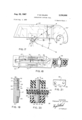
- FIG. 6 is an edge expanded view of one of the pivoted handles with its stripping blade backing plate adjacent the jaw portion thereof, of the tool shown in FIGS. 1, 2 or 3;
- FIG. 7 is an enlarged perspective view of the backing plate shown in FIG. 6;
- FIG. 8 is an enlarged perspective view of the integral stripping blades ready for mounting on said two cooperating handles for alignment before being separated by breaking along their center groove;
- FIG. 9 is a plan view of two cooperating handles with the blades and backing plates -mounted thereon for aligning of handle pivot pin holes;
- FIG. 10 is a side view lof the partial assembly of handles and blades shown in FIG. 9;
- FIG. 11 is an enlarged side view of one of the two identical plastic centering means for surrounding each jaw portion of the tool shown in FIG. 4;
- FIG. 12 is a plan view of the jaw face of the centering means shown in FIG. 11; Y
- FIG. 13 is an end view of the centering means shown in FIG. 11;
- FIG. 14 is an enlarged sectional view taken along line XIV-XIV in FIG. 2 of one assembled jaw and its pivot;
- FIG. 15 is a sectional view taken along line XV-XV in FIG. 14;
- FIG. 16 is an enlarged fragmentary view of a modified form of the invention showing alternate tooth form on the plastic centering means to maintain a constant distance from the pivot point for all ranges of insulated wire to be stripped, and also shows interlocking tabs or keys on the cutting blade backing plates to maintain alignment of their stripping recesses;
- FIG. 17 is an enlarged side view of one of lthe two plastic centering means shown in FIG. 16, showing the modified tooth form as well as the snap-on notched aperture for attachment to the pivot for the jaws;
- FIG. 18 is an enlarged ⁇ detail'view similar to FIG. 14, but showing a modified form of jaw pivot means and a backing plate on each side of the stripping blades;
- FIG. 19 is a fragmentary detail view taken along Iline XIX-XIX of FIG. 16 to show interlocking tabs or keys on the backing plates;
- FIG. 20 is an enlarged fragmentary view taken along line XX-XX of FIG. 16 showing the stripper in closed position on -an insulated wire with the cutting blades spaced from the wire itself and only partly cutting the insulation;
- FIG. 21 is an enla-rged perspective view of one of the modified backing plates shown in FIG. 16.
- an embodiment of the invention ha-s been shown as comprising a pa-ir of complemental members 20 of comparatively thin strip material formed into handle portions 22 and laterally offset portions 24 crossed and pivotally connected by pivot means 26 to provide a pair of jaw members 27 and 28.
- the jaw members 27 and 28 are disposed in edge to edge opposed relation (see FIGS. 5 and 15) in a common plane normal to the axis of the pivot means 26.
- Jaw members 27 and 28 support s-tripping blades 31 and 32 (see FIGS. 4, 5, 8, 9, 14, and 15) in edge yto edge relation, the blades having complemental cuttingl portions in the form of arcuate notches 35 and 36 in opposed edges there-of.
- the members 20 are fabricated of suitable strong an-d rigid lstrip-like material, preferably metal, and are of similar size and shape, each member 20 having an arcuate section at the offset portion 24 to separate the handle portions 22 in the plane of the jaws 27 and 28 upon assembly.
- a hole 38 is provided to receive the end portion of pivot means 26.
- the oiset portions 24 are oppositely -disposed and therefore spaced from each other as shown in FIGS. 3, and 14 and this aligns the handle portions 22 as well as positions the jaws 27 and 28 in edge to edge opposed relation in a common plane.
- the hand engaging parts of the handle portions 22 may be covered with insulating sleeves 29 or other material as desired.
- the pivot means 26 comprises a comparatively large diameter pin portion 40 (see FIG. 14) having reduced en-d portions 42, the end portions 42 serving as pivot means for handles 22 while the central portion 40 serves as the pivot for wire centering means 44 and 45 hereinafter described.
- Rivet means 47 protrude from one face of jaw 27 or 28, it being noted that the rivets 47 for a pair of jaws 27 and 28 extend from opposite faces thereof and thus extend in .the same direction when members are assembled. This provides for the assembly of the blades thereon in edge to edge relation, it being noted that the blades 31 and 32 have a pair of spaced holes 48 (see FIG. 8) to receive the rivets 47 for rigidly connecting the blades to the jaws 27 and 28.
- the s-tripper blades 31 and 32 mounted on the jaws 27 and 28 are initially formed as a single blank 50 as shown in FIGS. 8 and 9, and then the pivot holes 38 are drilled, punched or reamed to be in alignment with each other.
- the blank 50 is centrally perforated as at 52 to provide the insulation severing and stripping recesses 35 and 36 and is centrally scored at 54 to weaken the blank to be subsequently broken therealong to provide .two opposed blades.
- Plates 55 are provided in the form of plates 55 (see FIGS. 5, 6, 7, 9, 10, 14 and 15) to back up the stripping blades 31, 32, which plates 55 are generally similar to blades 31 and 32 but may be of increased thickness and are pr-ovided with wire receiving notches 57 having a somewhat larger radius than that of the stripping recesses 3S and 36 in the blades 31 and 32.
- Plates 55 are of generally rectangular shape and may be riveted by rivets 47 to the faces of jaw portions of the handles with the stripper blades 31 and 32 (or 50) between such jaw portions 27 an-d 28 and the pl-ates 55.
- Wire centering means in the form of auxiliary jaw means 44 and 45 may be identical and molded of plastic into generally rectangular shape having back 65 and side walls 67 interiorly recessed to receive the jaw members 27 yand 28.
- the centering element 44 or 45 may have a diagonal nose portion or forward end 60 (see FIGS. 2, 3, 4 and ⁇ 11) and an -arcuate extension 62 at the opposite end Iapertured at 63 for pivotal connection to the central portion 40 of pivot means 26 (see FIG. 14).
- Interiorly of the elements 44 and 45 is a generally H-shaped recess 64 (see FIG. 12) to freely accommodate the jaw, blade and backing plate assembly.
- a slot 68 is provided in the elements 44 and 45 so they may be readily iitted on the jaws 27 -and 28, with the extensions disposed between the offset portions 24 of the members 20.
- integral teeth means 70 Projecting outwardly from adjacent each side edge of elements 44 and 45 are integral teeth means 70 which provide a notch 72, there being a single pair of teeth 70 at one side and a laterally spaced double pair of teeth 70 at the other side. Being reversible for assembly on jaws 27 and 28, the single pair of teeth 70 of jaw 44 will iit between the double pair of teeth of jaw 45 to provide coacting means at each side of the jaws 27 and 28 to contact the insulated wire at spaced points to maintain the alignment of the core with the recesses 35 and 36 in the blades 31 and 32 (see FIGS. 4 and 5).
- a recess 75 (see FIGS. 1-5, 11-15 is provided in the wall 65 of members 44 and 45 to receive the inturned ends 76 of a C-spring 77, the bight 78 of which is disposed between the offsets 24 (see FIG. 3), the spring 77 4serving to apply closing force on the jaws 44 and 45 as well as on the jaws 27 and 28 while permitting lost motion between the .respective pairs of jaws. This permits the jaws 44 and 45 to accommodate wire of different gauges having various degrees of insulation thickness thereon.
- each tool may be built for stripping one gauge only to further insure that the core is not marred by inadvertent use of the improper stripping recesses in a multiple size stripping tool for example.
- the present tool may be successfully used on production lines and is preferably marked or color coded for the intended size of wire.
- FIGS. 1, 4-and 5 disclose the tool in use on an insulated wire 80, having a central wire filament 81 surrounded by a cylindrical tube of insulation 82.
- the wire is with the insulation 82 being held on both sides of the cutting blades 31 and 32 and in alignment with the cooperating semi-circular insulation cutting notches 35 and 36 therein, which notches only cut part way, such as about half way radially through the insulation 82 without contacting or scratching the surface of the wire 81.
- FIGS. 16 through 21 and with particular reference to FIG. 17, the wire centering means 45 is generally similar to that shown in FIG. 11 except that the teeth 70 have their confronting edges 84 and 85 arcuately formed.
- the purpose of this is to maintain a constant distance from the center of pivot means 26 to the center 81 of the core or lament 81 of all r-anges of wire to be stripped due to the different diameters of insulation thereon.
- the wire centering means will maintain during closing, of the stripping jaws, the position the center 81 of the core 81 more accurately with respect to the stripping recesses 35 and 36 (see FIG. 9) due to the curvature of the edges of the teeth that engage the insulation.
- the insulated wire 80 which may have the maximum diameter of insulation that can be accomodated by the tool shown, is engaged by the curved edges 84 and 85 of the teeth 70', which curved edges may have arcs having radii equal to the radius of the arc through the center 81 of the core 81 from the center 26 of pivot means 26.
- This may be accomplished for all practical purposes by offsetting the respective arrow-ended radii C and A of tooth edges 84 and 85 approximately 30 in opposite directions from the radius B through the center 81 of the core 81, while maintaining radii A, B, and C of equal length.
- the aperture 90 in extension 62' may be notched at 92 as shown in FIG. 17.
- the notch 92 is of slightly less width than the diameter of the central portion 40 of pivot means 26 so as to be snapped edgewise over the portion 40.
- the pivot means 26 may include a collar 93 (see FIG. 18) in which case the aperture 92 may be slightly larger than aperture 63.
- back up plates 95 may be provided on both sides of the blades 31 as particularly shown in FIGS. 18, 19 and 20.
- the plates 95 may be identical as shown in FIG. 2l, it being only necessary to arrange opposed plates so that a notch 96 of one blade is opposite a projection, tab, or key 98 ofthe other with the plates 95 on one side ofthe blades having their notches and projections staggered with respect to those on the other side of the blades.
- the radius of the notches 96 is only enough larger, than the radius of l the keys 98 to enter the notches, so that the semi-circular center notches 99 in the backing plates 95 and thus the stripping recesses 52 are in accurate alignment to sever the insulation 82 to the desired degree to prevent scratching or otherwise marring the wire core 81.
- a tool for stripping a tubular jacket off of a central tilament without contacting said filament comprising:
- jacket engaging means for engaging opposite sides of said jacket on both sides of said blades for maintaining the alignment of said lilament with said aperture during both the cutting and stripping operations of said tool, said jacket engaging means being movable with said blade until said jacket is firmly engaged by said jacket engaging means, whereupon said jacket engaging means remains substantially stationary as said blade moves further to cut said jacket.
- a tool according to claim 1 including means tor urging said pair of jacket engaging means toward each other for maintaining engagement with any jacket inserted therebetween.
- said urging means comprises a spring.
- a tool for stripping a tubular jacket olf of a central filament without contacting said tilament comprising:
- a pair of jacket engaging means having arcuate confronting faces for wedging opposite sides of said jacket on both sides of said blades for maintaining the alignment of said filament with said aperture during both the cutting and stripping operations of said tool.
- a wire stripping tool comprising:
- pivot means connecting said members together at said offset portions
- said wire centering means comprises a pair of identical plastic members surrounding said blades and having a wedge shaped notch on each side of each blade for eng-aging the outer surface of the part to be stripped from said wire.
- a tool for stripping insulation from a wire comprising:
- a wire stripping tool comprising:
- auxiliary jaw means embracing said jaw portions and having wire centering means for engaging a wire on each side of said blade members to support a wire during cutting and stripping.
- auxiliary jaw means comprises means on each side of said blade for aligning central Iilament of said wire with said notches.
- a wire stripping tool comprising:
- pivot means connecting said members together at said offset portions
- auxiliary jaw means on said auxiliary jaw means including two pairs of cooperating V-sh-aped notches for engaging the outer surface of a wire on both sides of said stripping blades to center said wire with respect to said jaw means.
- a tool according to claim 13 wherein said means on sai-d auxiliary jaw means includes a c-spring for urging said auxiliary jaw means together independently of the action of said jaw portions securing said stripping blades.
- auxiliary jaw means include means for mounting said auxiliary jaw means on said pivot means.
Landscapes
- Removal Of Insulation Or Armoring From Wires Or Cables (AREA)
Description
INSULATION CUTTING TOOL Filed Aug. 2, 1965 5 Sheets-Sheet l F |G 3 INVENTOR.
FREEMAN B. GALKIN ATTORNEY Aug. 22, 1967 F. B. CALKIN INSULATION CUTTING TOOL 5 Sheets-Sheet 2 Filed Aug. 2, 1965 FIG. 4
FIG. 6
FIG.5
INVENTOR. FREEMAN B. CALKN FIG.8
ATTORNEY Aug- 22 19.67 F. B. cALKlN 3,336,666
I INSULATION CUTTING TOOL Filed Aug. 2, 1965 5 Sheets-Sheet Z 62 Y f'. I 64 \\'M-J N 6 IL 7oj 712 L7o le? a: 70 42;' FIG. j
n 6 67 XY l ARI 7,2 527 f5 97 68 6242 26 e 2922 64 :LVO 24 22 FREEMAIS] CALKIN 70/72/ I 70 64 27 42 38 6 j XSI \4 BY FIG. I4 W ATTOR NEY ATTORNEY Aug'. 22, 1967 Filed Aug. 2, 1965 Aug. 22, 1967 F. B. cALKlN 3,336,666
INSULATION CUTTING TOOL Filed Aug. 2, 1965 5 Sheets-Sheet 5 FIG. IQ FIG. 2O ATTORNEY United States Patent G Ohio Filed Aug. 2, 1965, Ser. No. 476,326 15 Claims. (Cl. Sil-90.1)
This invention relates to a tool for stripping a jacket from a core or central filament such as a Wire. and is particularly directed to a plier-type stripping tool for cutting and removing insulation from wires so that the wire is not scratched or marred.
An object of the invention is to provide a (wire) stripping tool of compact size with accurately aligned cutting elements and means to hold the insulated wire in alignment with the cutting elements during cutting and stripping.
Another object of the invention is to provide a wire stripping tool with means for 4engaging and gripping the insulated wire on both sides of the cutting elements to support the wire at opposite sides of the cut to insure severence of insulation only and prevent scratches or marks on the wire core.
Another object of the invention is to provide a wire stripping tool with stripper blades produced from a single perforated and scored blank assembled with the tool jaws. and subsequently broken along the score to insure alignment of the stripper blades.
Another object of the invention is to provide a tool that can be economically produced from a minimum of different parts, the handles being identical as to size and shape as are the wire centering jaw means.
Still another object is to provide such a single pair of centering jaw members which can engage and grip many different diameters of insulation or coatings on filaments or wires.
Generally speaking, the invention contemplates a novel arrangement of elements of the tool wherein a pair of jaws, which may be on pivotally connected h-andles, are employed to accurately strip insulation from wires or filaments. These jaws are in edge-to-edge relation in a common plane, and if pivotally connected, this plane is normal to the axis of said pivotal connection. These jaws or jaw portions of the handles also are for supporting on one side of such jaws a pair of stripping blades or members also in edge-to-edge relation, the stripping members having complemental cutting notches in the opposed edges thereof. On each side of each jaw is a centering means which may be made of plastic and which moves with the jaws. If the jaws are on pivoted handles, these handles may have laterally offset portions spaced by pivot means about which a pair of these plastic centering means may also be pivoted for movement with the stripping jaws. These centering means have integral teeth -for engaging and holding la coated filament or an insulated wire at both sides of the stripping members to hold the filament or wire in position to insure severing of the insulation without engagement with the filament or wire core. The centering means may be urged toward closed position by a separate spring means, such as a C-spring which also may exert a closing force on the stripping jaws.
The above mentioned and other features and objects of this invention and the 4manner of attaining them will become more apparent and the invention itself will be understood best by reference to the following description of an embodiment of the invention taken in conjunction with the accompanying drawings, wherein:
FIG. 1 is a perspective view of a Wire strippig tool according to one embodiment of the present invention, with a wire in its jaws;
FIG. 2 is la plan view of the tool shown in FIG. 1;
FIG. 3 is a side view of the tool shown in FIG. 2;
FIG. 4 is an enlarged plan view of the jaw portions of the tool shown in FIG. 1 with an insulated Wire clamped therein ready for stripping;
FIG. 5 is a vertical section taken along line V-V lof FIG. 4 through the clamped wire;
FIG. 6 is an edge expanded view of one of the pivoted handles with its stripping blade backing plate adjacent the jaw portion thereof, of the tool shown in FIGS. 1, 2 or 3;
FIG. 7 is an enlarged perspective view of the backing plate shown in FIG. 6;
FIG. 8 is an enlarged perspective view of the integral stripping blades ready for mounting on said two cooperating handles for alignment before being separated by breaking along their center groove;
FIG. 9 is a plan view of two cooperating handles with the blades and backing plates -mounted thereon for aligning of handle pivot pin holes;
FIG. 10 is a side view lof the partial assembly of handles and blades shown in FIG. 9;
FIG. 11 is an enlarged side view of one of the two identical plastic centering means for surrounding each jaw portion of the tool shown in FIG. 4;
FIG. 12 is a plan view of the jaw face of the centering means shown in FIG. 11; Y
FIG. 13 is an end view of the centering means shown in FIG. 11;
FIG. 14 is an enlarged sectional view taken along line XIV-XIV in FIG. 2 of one assembled jaw and its pivot; FIG. 15 is a sectional view taken along line XV-XV in FIG. 14;
FIG. 16 is an enlarged fragmentary view of a modified form of the invention showing alternate tooth form on the plastic centering means to maintain a constant distance from the pivot point for all ranges of insulated wire to be stripped, and also shows interlocking tabs or keys on the cutting blade backing plates to maintain alignment of their stripping recesses;
FIG. 17 is an enlarged side view of one of lthe two plastic centering means shown in FIG. 16, showing the modified tooth form as well as the snap-on notched aperture for attachment to the pivot for the jaws;
FIG. 18 is an enlarged `detail'view similar to FIG. 14, but showing a modified form of jaw pivot means and a backing plate on each side of the stripping blades;
FIG. 19 is a fragmentary detail view taken along Iline XIX-XIX of FIG. 16 to show interlocking tabs or keys on the backing plates;
FIG. 20 is an enlarged fragmentary view taken along line XX-XX of FIG. 16 showing the stripper in closed position on -an insulated wire with the cutting blades spaced from the wire itself and only partly cutting the insulation; and
FIG. 21 is an enla-rged perspective view of one of the modified backing plates shown in FIG. 16.
Referring to the dnawings, :an embodiment of the invention ha-s been shown as comprising a pa-ir of complemental members 20 of comparatively thin strip material formed into handle portions 22 and laterally offset portions 24 crossed and pivotally connected by pivot means 26 to provide a pair of jaw members 27 and 28. The jaw members 27 and 28 are disposed in edge to edge opposed relation (see FIGS. 5 and 15) in a common plane normal to the axis of the pivot means 26. Jaw members 27 and 28 support s-tripping blades 31 and 32 (see FIGS. 4, 5, 8, 9, 14, and 15) in edge yto edge relation, the blades having complemental cuttingl portions in the form of arcuate notches 35 and 36 in opposed edges there-of.
The members 20 are fabricated of suitable strong an-d rigid lstrip-like material, preferably metal, and are of similar size and shape, each member 20 having an arcuate section at the offset portion 24 to separate the handle portions 22 in the plane of the jaws 27 and 28 upon assembly. At the forward end of portion 24, a hole 38 (see FIGS. 9 and 14) is provided to receive the end portion of pivot means 26. The oiset portions 24 are oppositely -disposed and therefore spaced from each other as shown in FIGS. 3, and 14 and this aligns the handle portions 22 as well as positions the jaws 27 and 28 in edge to edge opposed relation in a common plane. The hand engaging parts of the handle portions 22 may be covered with insulating sleeves 29 or other material as desired.
The pivot means 26 comprises a comparatively large diameter pin portion 40 (see FIG. 14) having reduced en-d portions 42, the end portions 42 serving as pivot means for handles 22 while the central portion 40 serves as the pivot for wire centering means 44 and 45 hereinafter described.
Rivet means 47 (see FIGS. 6, 9, l0 and 14) protrude from one face of jaw 27 or 28, it being noted that the rivets 47 for a pair of jaws 27 and 28 extend from opposite faces thereof and thus extend in .the same direction when members are assembled. This provides for the assembly of the blades thereon in edge to edge relation, it being noted that the blades 31 and 32 have a pair of spaced holes 48 (see FIG. 8) to receive the rivets 47 for rigidly connecting the blades to the jaws 27 and 28.
An important feature of this invention is that the s-tripper blades 31 and 32 mounted on the jaws 27 and 28 are initially formed as a single blank 50 as shown in FIGS. 8 and 9, and then the pivot holes 38 are drilled, punched or reamed to be in alignment with each other. The blank 50 is centrally perforated as at 52 to provide the insulation severing and stripping recesses 35 and 36 and is centrally scored at 54 to weaken the blank to be subsequently broken therealong to provide .two opposed blades.
-Means are provided in the form of plates 55 (see FIGS. 5, 6, 7, 9, 10, 14 and 15) to back up the stripping blades 31, 32, which plates 55 are generally similar to blades 31 and 32 but may be of increased thickness and are pr-ovided with wire receiving notches 57 having a somewhat larger radius than that of the stripping recesses 3S and 36 in the blades 31 and 32. Plates 55 are of generally rectangular shape and may be riveted by rivets 47 to the faces of jaw portions of the handles with the stripper blades 31 and 32 (or 50) between such jaw portions 27 an-d 28 and the pl-ates 55.
Wire centering means in the form of auxiliary jaw means 44 and 45 (see FIGS. 11, 12 and 13) may be identical and molded of plastic into generally rectangular shape having back 65 and side walls 67 interiorly recessed to receive the jaw members 27 yand 28. The centering element 44 or 45 may have a diagonal nose portion or forward end 60 (see FIGS. 2, 3, 4 and `11) and an -arcuate extension 62 at the opposite end Iapertured at 63 for pivotal connection to the central portion 40 of pivot means 26 (see FIG. 14). Interiorly of the elements 44 and 45 is a generally H-shaped recess 64 (see FIG. 12) to freely accommodate the jaw, blade and backing plate assembly. To accommodate the handle at the forward end of the offset 24, a slot 68 is provided in the elements 44 and 45 so they may be readily iitted on the jaws 27 -and 28, with the extensions disposed between the offset portions 24 of the members 20.
Projecting outwardly from adjacent each side edge of elements 44 and 45 are integral teeth means 70 which provide a notch 72, there being a single pair of teeth 70 at one side and a laterally spaced double pair of teeth 70 at the other side. Being reversible for assembly on jaws 27 and 28, the single pair of teeth 70 of jaw 44 will iit between the double pair of teeth of jaw 45 to provide coacting means at each side of the jaws 27 and 28 to contact the insulated wire at spaced points to maintain the alignment of the core with the recesses 35 and 36 in the blades 31 and 32 (see FIGS. 4 and 5).
A recess 75 (see FIGS. 1-5, 11-15 is provided in the wall 65 of members 44 and 45 to receive the inturned ends 76 of a C-spring 77, the bight 78 of which is disposed between the offsets 24 (see FIG. 3), the spring 77 4serving to apply closing force on the jaws 44 and 45 as well as on the jaws 27 and 28 while permitting lost motion between the .respective pairs of jaws. This permits the jaws 44 and 45 to accommodate wire of different gauges having various degrees of insulation thickness thereon.
In view of the provision of blades 31 and 32 with but one pair of stripping recesses 35 and 36, different pairs of blades 31 and 32 are contemplated for tools for specific gauges of wire. In other words, each tool may be built for stripping one gauge only to further insure that the core is not marred by inadvertent use of the improper stripping recesses in a multiple size stripping tool for example. Thus, the present tool may be successfully used on production lines and is preferably marked or color coded for the intended size of wire.
FIGS. 1, 4-and 5 disclose the tool in use on an insulated wire 80, having a central wire filament 81 surrounded by a cylindrical tube of insulation 82. In FIGS. 4 and 5 specifically the wire is with the insulation 82 being held on both sides of the cutting blades 31 and 32 and in alignment with the cooperating semi-circular insulation cutting notches 35 and 36 therein, which notches only cut part way, such as about half way radially through the insulation 82 without contacting or scratching the surface of the wire 81. By holding the insulation 82 on both sides of the cutting blades 31 and 32, there is avoided any further cutting through the insulation 82 during the stripping operation when the tool is moved longitudinally of the wire 80 to break olf the partly severed insulation 82 and pull it off of the short end of the wire 80 from which it is to be removed or stripped.
A modified form of the invention is shown in FIGS. 16 through 21 and with particular reference to FIG. 17, the wire centering means 45 is generally similar to that shown in FIG. 11 except that the teeth 70 have their confronting edges 84 and 85 arcuately formed. The purpose of this is to maintain a constant distance from the center of pivot means 26 to the center 81 of the core or lament 81 of all r-anges of wire to be stripped due to the different diameters of insulation thereon. In other words, it has been found that the wire centering means will maintain during closing, of the stripping jaws, the position the center 81 of the core 81 more accurately with respect to the stripping recesses 35 and 36 (see FIG. 9) due to the curvature of the edges of the teeth that engage the insulation. As is shown in FIG. 16, the insulated wire 80, which may have the maximum diameter of insulation that can be accomodated by the tool shown, is engaged by the curved edges 84 and 85 of the teeth 70', which curved edges may have arcs having radii equal to the radius of the arc through the center 81 of the core 81 from the center 26 of pivot means 26. This may be accomplished for all practical purposes by offsetting the respective arrow-ended radii C and A of tooth edges 84 and 85 approximately 30 in opposite directions from the radius B through the center 81 of the core 81, while maintaining radii A, B, and C of equal length.
To facilitate assembly of the wire centering means 44 and 45 on the jaws 27 and 28, the aperture 90 in extension 62' may be notched at 92 as shown in FIG. 17. The notch 92 is of slightly less width than the diameter of the central portion 40 of pivot means 26 so as to be snapped edgewise over the portion 40. It will be noted further that if desired the pivot means 26 may include a collar 93 (see FIG. 18) in which case the aperture 92 may be slightly larger than aperture 63.
To insure better alignment of the stripping recesses 35 and 36, back up plates 95 may be provided on both sides of the blades 31 as particularly shown in FIGS. 18, 19 and 20. The plates 95 may be identical as shown in FIG. 2l, it being only necessary to arrange opposed plates so that a notch 96 of one blade is opposite a projection, tab, or key 98 ofthe other with the plates 95 on one side ofthe blades having their notches and projections staggered with respect to those on the other side of the blades. The radius of the notches 96 is only enough larger, than the radius of l the keys 98 to enter the notches, so that the semi-circular center notches 99 in the backing plates 95 and thus the stripping recesses 52 are in accurate alignment to sever the insulation 82 to the desired degree to prevent scratching or otherwise marring the wire core 81.
While there is described above the principles of this invention in connection with specific apparatus, it is to be clearly understood that this description is made only by way of example and not as a limitation to the scope of this invention.
What is claimed is:
1. A tool for stripping a tubular jacket off of a central tilament without contacting said filament, comprising:
a pair of cooperating cutting blades for said jacket having an aperture between them slightly larger than the outside diameter of said tilament, and
a pair of jacket engaging means for engaging opposite sides of said jacket on both sides of said blades for maintaining the alignment of said lilament with said aperture during both the cutting and stripping operations of said tool, said jacket engaging means being movable with said blade until said jacket is firmly engaged by said jacket engaging means, whereupon said jacket engaging means remains substantially stationary as said blade moves further to cut said jacket.
2. A tool according to claim 1 wherein said tool oomprises a pair of pivoted handles having jaw portions for mounting said cutting blades and said jacket engaging means.
3. A tool according to claim 1 including means tor urging said pair of jacket engaging means toward each other for maintaining engagement with any jacket inserted therebetween.
4. A tool according to claim 3 wherein said urging means comprises a spring.
5. A tool for stripping a tubular jacket olf of a central filament without contacting said tilament, comprising:
a pair of cooperating cutting blades for said jacket having an aperture between them slightly larger than the outside diameter of said filament, and
a pair of jacket engaging means having arcuate confronting faces for wedging opposite sides of said jacket on both sides of said blades for maintaining the alignment of said filament with said aperture during both the cutting and stripping operations of said tool.
6. A wire stripping tool comprising:
a pair of pivoted members having jaw portions and handle portions connected by laterally offset portions,
pivot means connecting said members together at said offset portions,
stripping blades secured to said jaw portions in opposed edge to edge relation in a common plane normal to the axis of said pivot means, and
a pair of wire centering means on each side of said blades pivoted about said pivot means for movement with and independently of said jaw portions for aligning wire having various degrees of insulation thereon with said stripping blades.
7. A tool according to claim 6 wherein said blade has cooperating notches therein to cut only part way through the part to be stripped from said Wire.
8. A tool according to claim 6 wherein said wire centering means comprises a pair of identical plastic members surrounding said blades and having a wedge shaped notch on each side of each blade for eng-aging the outer surface of the part to be stripped from said wire.
9. A tool for stripping insulation from a wire comprising:
a pair of pivotally connected wire stripping jaws having handle portions for actuating said jaws; complemental cutting elements secured to s-aid jaws for movement therewith,
a pair of auxiliary jaw means embracing said stripping jaws; and
complemental teeth integral with said auxiliary jaw means for engaging and holding an insulated wire on both sides of said cutting elements.
10. A tool according to claim 9 wherein said cutting elements only cut part way through the insulation on said insulated wire.
11. A wire stripping tool comprising:
a pair of complemental pivotally connected members having handle portions and jaw portions connected by offset portions, pivot means connecting said members together at said oset portions,
blade members secured to said jaw portions in edge to edge relation and having complemental insulation stripping notches, and v auxiliary jaw means embracing said jaw portions and having wire centering means for engaging a wire on each side of said blade members to support a wire during cutting and stripping.
12. A tool according to claim 11 wherein said auxiliary jaw means comprises means on each side of said blade for aligning central Iilament of said wire with said notches.
13. A wire stripping tool comprising:
a pair of pivotally connected members having jaw portions and handle portions connected by otiset portions,
pivot means connecting said members together at said offset portions,
complemental stripping blades secured to said jaw portions, auxiliary jaw means embracing said jaw p0rtions, and
means on said auxiliary jaw means including two pairs of cooperating V-sh-aped notches for engaging the outer surface of a wire on both sides of said stripping blades to center said wire with respect to said jaw means.
14. A tool according to claim 13 wherein said means on sai-d auxiliary jaw means includes a c-spring for urging said auxiliary jaw means together independently of the action of said jaw portions securing said stripping blades.
15. A tool according to claim 13 wherein said auxiliary jaw means include means for mounting said auxiliary jaw means on said pivot means.
References Cited UNITED STATES PATENTS 2,407,233 9/1946 Greer et al 30-91.2 2,585,080 2/1952 Beaulieu et al. 30-91.2 2,902,894 9/1959 Koos 8 l-9.5 3,125,909 y 3/1964 Hindenburg 81-9.5 3,151,509 'l0/1964 Gormley 30-9l.2 3,161,087 12/1964 Bartley 81-95 3,241,407 3/ 1966 Oehlerking 8 1-9.51 FOREIGN PATENTS 3 32,906 7/ 1919 Germany.
468,088 11/ 1928 Germany.
WILLIAM FELDMAN, Primary Examiner'. MILTON S. MEHR, Examiner.
Claims (1)
1. A TOOL FOR STRIPPING A TUBULAR JACKET OFF OF A CENTRAL FILAMENT WITHOUT CONTACTING SAID FILAMENT, COMPRISING: A PAIR OF COOPERATING CUTTING BLADES FOR SAID JACKET HAVING AN APERTURE BETWEEN THEM SLIGHTLY LARGER THAN THE OUTSIDE DIAMETER OF SAID FILAMENT, AND A PAIR OF JACKET ENGAGING MEANS FOR ENGAGING OPPOSITE SIDES OF SAID JACKET ON BOTH SIDES OF SAID BLADES FOR MAINTAINING THE ALIGNMENT OF SAID FILAMENT WITH SAID APERTURE DURING BOTH THE CUTTING SAID STRIPPING OPERATIONS OF SAID TOOL, SAID JACKET ENGAGING MEANS BEING MOVABLE WITH SAID BLADE UNTIL SAID JACKET IS FIRMLY ENGAGED BY SAID JACKET ENGAGING MEANS, WHEREUPON SAID JACKET ENGAGING MEANS REMAINS SUBSTANTIALLY STATIONARY AS SAID BLADE MOVES FURTHER TO CUT SAID JACKET.
Priority Applications (1)
| Application Number | Priority Date | Filing Date | Title |
|---|---|---|---|
| US476326A US3336666A (en) | 1965-08-02 | 1965-08-02 | Insulation cutting tool |
Applications Claiming Priority (1)
| Application Number | Priority Date | Filing Date | Title |
|---|---|---|---|
| US476326A US3336666A (en) | 1965-08-02 | 1965-08-02 | Insulation cutting tool |
Publications (1)
| Publication Number | Publication Date |
|---|---|
| US3336666A true US3336666A (en) | 1967-08-22 |
Family
ID=23891399
Family Applications (1)
| Application Number | Title | Priority Date | Filing Date |
|---|---|---|---|
| US476326A Expired - Lifetime US3336666A (en) | 1965-08-02 | 1965-08-02 | Insulation cutting tool |
Country Status (1)
| Country | Link |
|---|---|
| US (1) | US3336666A (en) |
Cited By (23)
| Publication number | Priority date | Publication date | Assignee | Title |
|---|---|---|---|---|
| FR2166306A1 (en) * | 1972-01-07 | 1973-08-17 | Honeywell Bull | |
| US3854202A (en) * | 1972-10-13 | 1974-12-17 | G Cortese | Wire cutter for electrical use |
| US4226145A (en) * | 1979-06-25 | 1980-10-07 | Gill John F | Wire stripper |
| US4246808A (en) * | 1979-03-09 | 1981-01-27 | Ideal Industries, Inc. | Precision small wire stripper and blade structure |
| US4317283A (en) * | 1980-08-28 | 1982-03-02 | Grumman Aerospace Corporation | Stripper tool |
| US4480509A (en) * | 1983-03-25 | 1984-11-06 | Hydary Mainul H | Automatic wire stripper |
| EP0419748A1 (en) * | 1988-03-30 | 1991-04-03 | André Laurencot | Combination tool for cutting and stripping the ends of electric leads covered with an insulating sleeve |
| US5074043A (en) * | 1990-11-26 | 1991-12-24 | Mills Edward O | Safety-cable jacket remover |
| US5101693A (en) * | 1991-08-05 | 1992-04-07 | Alco Industries, Inc. | Insulation cutting and stripping tool |
| USD387965S (en) * | 1988-11-18 | 1997-12-23 | Ronan John S | Shears |
| USD427659S (en) * | 1998-09-03 | 2000-07-04 | Scott Gordon Lewis | Fishing line fastening tool |
| USD434955S (en) * | 1997-06-26 | 2000-12-12 | Ronan John S | Shears |
| US6439084B1 (en) | 2001-05-07 | 2002-08-27 | Ideal Industries, Inc. | Laminated blade assembly for cutting insulation |
| US20030172533A1 (en) * | 2002-03-15 | 2003-09-18 | Alexander Pamela K. | Scissors type element for sectioning and retaining a candle wick |
| US6813832B2 (en) * | 2002-03-15 | 2004-11-09 | Pamela K. Alexander | Scissors type implement for sectioning and retaining a candle wick |
| US20050028373A1 (en) * | 2003-08-08 | 2005-02-10 | Murphy Stacey A. | Blade assembly |
| US20060161182A1 (en) * | 2005-01-19 | 2006-07-20 | Applied Medical Resources Corporation | Single fire vascular clip applier with disposable jaw |
| US20150265501A1 (en) * | 2014-03-21 | 2015-09-24 | Tyson Triplett | Pill cutting and storage device |
| USD763646S1 (en) * | 2014-05-09 | 2016-08-16 | Cummins Inc. | Scissors guard |
| WO2019152290A1 (en) * | 2018-02-02 | 2019-08-08 | Jukka Llc | Oven door for a vending machine |
| US10584870B2 (en) * | 2018-06-05 | 2020-03-10 | Taylor White | Candle wick trimming assembly |
| USD933847S1 (en) | 2020-01-17 | 2021-10-19 | Studio 010 Inc. | Pill splitter |
| US11672735B2 (en) | 2020-01-17 | 2023-06-13 | Studio 010 Inc. | Pill splitter |
Citations (9)
| Publication number | Priority date | Publication date | Assignee | Title |
|---|---|---|---|---|
| DE332906C (en) * | 1919-07-23 | 1921-02-11 | Aeg | Pliers for removing the insulation from electrical conductors |
| DE468088C (en) * | 1926-04-29 | 1928-11-07 | Siemens Schuckertwerke Akt Ges | Installation pliers |
| US2407233A (en) * | 1944-02-21 | 1946-09-10 | John J Greer | Insulated wire stripping device |
| US2585080A (en) * | 1948-05-27 | 1952-02-12 | Western Electric Co | Wire stripping pliers |
| US2902894A (en) * | 1957-01-11 | 1959-09-08 | Jr Milton Koos | Wire stripper |
| US3125909A (en) * | 1961-03-14 | 1964-03-24 | figure | |
| US3151509A (en) * | 1961-09-26 | 1964-10-06 | Harry L Gormley | Wire stripping tool having blades with aligning means |
| US3161087A (en) * | 1962-07-10 | 1964-12-15 | Bartley Mfg Company Inc | Wire stripping tool |
| US3241407A (en) * | 1964-10-05 | 1966-03-22 | Ideal Ind | Adjustable collet wire guide for a wire stripper |
-
1965
- 1965-08-02 US US476326A patent/US3336666A/en not_active Expired - Lifetime
Patent Citations (9)
| Publication number | Priority date | Publication date | Assignee | Title |
|---|---|---|---|---|
| DE332906C (en) * | 1919-07-23 | 1921-02-11 | Aeg | Pliers for removing the insulation from electrical conductors |
| DE468088C (en) * | 1926-04-29 | 1928-11-07 | Siemens Schuckertwerke Akt Ges | Installation pliers |
| US2407233A (en) * | 1944-02-21 | 1946-09-10 | John J Greer | Insulated wire stripping device |
| US2585080A (en) * | 1948-05-27 | 1952-02-12 | Western Electric Co | Wire stripping pliers |
| US2902894A (en) * | 1957-01-11 | 1959-09-08 | Jr Milton Koos | Wire stripper |
| US3125909A (en) * | 1961-03-14 | 1964-03-24 | figure | |
| US3151509A (en) * | 1961-09-26 | 1964-10-06 | Harry L Gormley | Wire stripping tool having blades with aligning means |
| US3161087A (en) * | 1962-07-10 | 1964-12-15 | Bartley Mfg Company Inc | Wire stripping tool |
| US3241407A (en) * | 1964-10-05 | 1966-03-22 | Ideal Ind | Adjustable collet wire guide for a wire stripper |
Cited By (27)
| Publication number | Priority date | Publication date | Assignee | Title |
|---|---|---|---|---|
| FR2166306A1 (en) * | 1972-01-07 | 1973-08-17 | Honeywell Bull | |
| US3854202A (en) * | 1972-10-13 | 1974-12-17 | G Cortese | Wire cutter for electrical use |
| US4246808A (en) * | 1979-03-09 | 1981-01-27 | Ideal Industries, Inc. | Precision small wire stripper and blade structure |
| US4226145A (en) * | 1979-06-25 | 1980-10-07 | Gill John F | Wire stripper |
| US4317283A (en) * | 1980-08-28 | 1982-03-02 | Grumman Aerospace Corporation | Stripper tool |
| US4480509A (en) * | 1983-03-25 | 1984-11-06 | Hydary Mainul H | Automatic wire stripper |
| EP0419748A1 (en) * | 1988-03-30 | 1991-04-03 | André Laurencot | Combination tool for cutting and stripping the ends of electric leads covered with an insulating sleeve |
| USD387965S (en) * | 1988-11-18 | 1997-12-23 | Ronan John S | Shears |
| US5074043A (en) * | 1990-11-26 | 1991-12-24 | Mills Edward O | Safety-cable jacket remover |
| US5101693A (en) * | 1991-08-05 | 1992-04-07 | Alco Industries, Inc. | Insulation cutting and stripping tool |
| USD434955S (en) * | 1997-06-26 | 2000-12-12 | Ronan John S | Shears |
| USD427659S (en) * | 1998-09-03 | 2000-07-04 | Scott Gordon Lewis | Fishing line fastening tool |
| US6439084B1 (en) | 2001-05-07 | 2002-08-27 | Ideal Industries, Inc. | Laminated blade assembly for cutting insulation |
| US20030172533A1 (en) * | 2002-03-15 | 2003-09-18 | Alexander Pamela K. | Scissors type element for sectioning and retaining a candle wick |
| US6813832B2 (en) * | 2002-03-15 | 2004-11-09 | Pamela K. Alexander | Scissors type implement for sectioning and retaining a candle wick |
| US20050028373A1 (en) * | 2003-08-08 | 2005-02-10 | Murphy Stacey A. | Blade assembly |
| US7000322B2 (en) * | 2003-08-08 | 2006-02-21 | Ideal Industries, Inc. | Blade assembly |
| US20060161182A1 (en) * | 2005-01-19 | 2006-07-20 | Applied Medical Resources Corporation | Single fire vascular clip applier with disposable jaw |
| US7842045B2 (en) * | 2005-01-19 | 2010-11-30 | Applied Medical Resources Corporation | Single fire vascular clip applier with disposable jaw |
| US20150265501A1 (en) * | 2014-03-21 | 2015-09-24 | Tyson Triplett | Pill cutting and storage device |
| US10245215B2 (en) * | 2014-03-21 | 2019-04-02 | Tyson Triplett | Pill cutting and storage device |
| USD763646S1 (en) * | 2014-05-09 | 2016-08-16 | Cummins Inc. | Scissors guard |
| WO2019152290A1 (en) * | 2018-02-02 | 2019-08-08 | Jukka Llc | Oven door for a vending machine |
| US10584870B2 (en) * | 2018-06-05 | 2020-03-10 | Taylor White | Candle wick trimming assembly |
| USD933847S1 (en) | 2020-01-17 | 2021-10-19 | Studio 010 Inc. | Pill splitter |
| US11672735B2 (en) | 2020-01-17 | 2023-06-13 | Studio 010 Inc. | Pill splitter |
| US11938095B1 (en) | 2020-01-17 | 2024-03-26 | Studio 010 Inc. | Pill splitter |
Similar Documents
| Publication | Publication Date | Title |
|---|---|---|
| US3336666A (en) | Insulation cutting tool | |
| US3831207A (en) | Multipurpose pliers | |
| US20080210058A1 (en) | Stripper Tool For Sheathed Cable | |
| US4607544A (en) | Tool for cutting, stripping and connecting electric wire | |
| JPH04229976A (en) | Tool for clamping double connection part between connector and conductor and insulation | |
| US4614001A (en) | Multipurpose plier | |
| US20140345061A1 (en) | High voltage cable preparation tool | |
| US4057863A (en) | Plier assembly | |
| JPH0429281B2 (en) | ||
| US4587731A (en) | Tool for cutting and stripping cable | |
| US3120773A (en) | Crimp tool and dies | |
| US3934286A (en) | Hand tool | |
| US4152797A (en) | Precision small wire and untwisting tool | |
| CA2042746C (en) | Crimping tool having improved crimping dies | |
| US3771222A (en) | An apparatus for cutting and core-stripping an electric cord | |
| US6439084B1 (en) | Laminated blade assembly for cutting insulation | |
| US4329891A (en) | Wire stripping tools | |
| US4480509A (en) | Automatic wire stripper | |
| US1692030A (en) | Wire-insulation stripper | |
| US3921237A (en) | Thinwall reaming pliers for electrical conduit | |
| US698567A (en) | Implement for stripping insulation from wire. | |
| US4311069A (en) | Wire pulling hand tool | |
| US2742696A (en) | Twin lead cutting tool | |
| US3965719A (en) | Cutting attachment for crimping tool | |
| US2758490A (en) | Insulation cutting tool |
Legal Events
| Date | Code | Title | Description |
|---|---|---|---|
| AS | Assignment |
Owner name: ALCO INDUSTRIES, INC. Free format text: ASSIGNMENT OF ASSIGNORS INTEREST.;ASSIGNOR:ALCO STANDARD CORPORATION;REEL/FRAME:004289/0479 Effective date: 19840217 Owner name: ALCO INDUSTRIES, INC. Free format text: ASSIGNMENT OF ASSIGNORS INTEREST;ASSIGNOR:ALCO STANDARD CORPORATION;REEL/FRAME:004289/0479 Effective date: 19840217 |