US3182589A - Printing and drying apparatus - Google Patents
Printing and drying apparatus Download PDFInfo
- Publication number
- US3182589A US3182589A US167725A US16772562A US3182589A US 3182589 A US3182589 A US 3182589A US 167725 A US167725 A US 167725A US 16772562 A US16772562 A US 16772562A US 3182589 A US3182589 A US 3182589A
- Authority
- US
- United States
- Prior art keywords
- conveyor
- baskets
- objects
- printing
- cylindrical
- Prior art date
- Legal status (The legal status is an assumption and is not a legal conclusion. Google has not performed a legal analysis and makes no representation as to the accuracy of the status listed.)
- Expired - Lifetime
Links
Images


Classifications
-
- B—PERFORMING OPERATIONS; TRANSPORTING
- B41—PRINTING; LINING MACHINES; TYPEWRITERS; STAMPS
- B41F—PRINTING MACHINES OR PRESSES
- B41F15/00—Screen printers
- B41F15/08—Machines
- B41F15/0872—Machines for printing on articles having essentially cylindrical surfaces
Definitions
- Silk screen printers have been designed and built which handle bottles or cans in a semi-automatic manner and which have a relatively high rate of printing so that a large number of objects can be handled in a relatively small time.
- Most automatic or semi-automatic silk screen printers for bottles or cans are provided with an automatic feeding arrangement and a rotary holding mechanism which picks up the individual can or bottle, moves it into contact with the silk screen and after printing is complete discharges the can or bottle to a suitable drying apparatus or to a container.
- the bottle or can which is being printed is first taken up by the machine it is moved into contact with the stencil for printing. At that point in the movement the stencil is moved and the can or bottle is rotated and ink is forced through the stencil to imprint the desired design and/ or words on the surface thereof.
- a silk screen printer In the processing of cylindrical containers such as cans, bottles and the like the silk screen printing process for applying designs and/or words must compete with other printing processes and automatic labelling machinery (machinery which automatically applies printed labels to the containers). In order to be competitive with other printing techniques and automatic labelling machines, a silk screen printer must be capable of handling the objects to be printed at a relatively high rate of speed.
- One of the problems which has arisen in the high speed printing and discharging of printed cylindrical containers from silk screen printers has been the handling of the containers for drying of the ink thereon after leaving the printer. It is necessary for a cylindrical object which is freshly printed to be handled in a manner such that it can be dried rapidly and conveniently without contacting the supporting surface whereby it might become smudged. The handling of printed objects for drying has therefore become a limiting factor in the speed at which the silk screen printer can handle the printing of cylindrical containers.
- Another object of this invention is the provision of a new and improved apparatus for printing and drying cylin drical containers which includes a conveyor arrangement having individual baskets which are of a size and shape such that cylindrical containers may be supported therein without smudging the wet ink thereon and which provide for free circulation of air around the printed objects.
- Still another object of this invention is the provision of a new and improved conveyor for drying cylindrical objects received from a printer which includes a plurality of supporting baskets which are arranged for passage through a drying oven and for dumping at a predetermined location outside the oven.
- Still another object of this invention is the provision of an improved drier for printed cylindrical objects received from a printer which is provided with a conveyor arranged for multiple passes of the objects .0 be dried through the drying oven.
- a feature of this invention is the provision of an improved printing apparatus including means for receiving and printing cylindrical containers and drying means including a conveyor having a plurality of spaced baskets positioned to receive the cylindrical objects and shaped to support the objects only at the end portions thereof.
- Another feature of this invention is the provision of an improved printing apparatus including a drier having a conveyor portion with baskets formed of wire and shaped to provide a curved receptacle in which a cylindrical object can be supported with only its ends touching the sides of the baskets.
- Still another feature of this invention is the pro-vision of an improved drying apparatus having a conveyor consisting of a pair of endless chain belts with a plurality of wire baskets supported therebetween which are arranged to receive cylindrical printed objects and support the same with only the end portions touching the walls of the baskets and having means on each basket cooperable with portions of the supporting frame work of the conveyor to cause the baskets to dump their contents at a predetermined position.
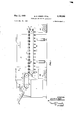
- FIGURE 1 is a partially diagrammatic view, in elevation, of a combined printing and drying apparatus utilizing the principles of this invention
- FIGURE 2 is a vertical elevation, partially in section, of the conveyor apparatus used in the drying portion of the combined printer and drier.
- FIGURE 3 is a plan view of the conveyor portion of the apparatus shown in FIGURE 2,
- FIGURE 4 is an end view, partially in section, of the conveyor apparatus shown in FIGS. 2 and 3 and showing details of the supporting basket of the conveyor,
- FIGURE 5 is a detail plan view of the conveyor basket shown in FIGS. 1-4.
- FIGURE 6 is a diagrammatic view in elevation and partially in section showing an alternate embodiment of the invention in which the conveyor is arranged for multiple passes through the drying oven.
- FIGURE 1 there is shown in combination a silk screen printer 1 and drier 3 arranged in tandem so that the drier receives objects discharged from the printer and handles them for drying without smudging the ink on the printed objects.
- Printer 1 can be any suitable printing apparatus for cylindrical containers, such as a rotary printer, but is preferably a silk screen printer a provided with the usual silk screen stencil and associated apparatus for movement of the stencil in coordination with the rotation of the object being printed. Details of the printer are not shown in the drawing since any suitable silk screen printer could be used.
- the drawing however shows the essential features of the usual silk screen printer which is arranged for semi-automatic or automatic operation.
- Printer 1 is provided with a suitable feed mechanism 5 for feeding a plurality of cylindrical containers 7 to be printed. While feeder 5 is shown as a gravity feed it may be a conveyor or other type feed mechanism for supplying individual objects to be printed.
- the cylindrical containers 7 are taken from feed mechanism 5 and moved into contact with silk screen stencil 9 where the cylindrical container is rotated in contact with the stencil and printed with the desired design and/or words.
- the cylindrical object which has been printed is moved by the supporting means, not shown, and placed on a conveyor mechanism 11 from which the cylindrical containers are discharged to the conveyor 13 of drier 3.
- the cylindrical containers are moved by a suitable rotary supporting means from the feeding means 5 into contact with silk screen printer 9 and discharged on conveyor 11 from which the objects are discharged to conveyor 13 of drier 3.
- conveyor 11 could be eliminated and the supporting means arranged to discharge printed objects directly to conveyor 13 of drier 3.
- Drier 3 consists of a suitable housing or enclosure 15 which may be a drying oven provided with drying means 17 which can be a plurality of heating lamps or a means for circulating heated air in contact with the objects passing through the drier.
- Drier 3 includes a supporting framework supporting a conveyor 13 having a plurality of supporting baskets 19 movable in coordination with the discharging means, i.e. conveyor 11, on silk screen printer 1 and having each basket positioned to receive a cylindrical container from conveyor 11.
- Conveyor baskets 19 are arranged with open sides for circulation of air for drying printing on the cylindrical objects received from printer 1 and are of a size and shape to support cylindrical objects only at the ends thereof.
- Conveyor baskets 19 are individually supported on endless supporting chains mounted on supporting wheels in a manner to be described more fully hereafter. Baskets 19 are preferably arranged to swing freely and support objects therein in a horizontal position.
- the conveyor is arranged so that baskets 19 may be tipped at the outer end 21 of the conveyor to discharge cylindrical containers 7 into a suitable receptacle 23.
- the apparatus can be adjusted to permit passage of the printed objects to be dried back through the drier on the underside of the conveyor and baskets 19 then tipped at the inlet end portion on the lower side of the conveyor to discharge the dried printed objects into a receptacle indicated in dotted lines at 25.
- the construction and mode of operation of the conveyor and the shape and operation of the supporting conveyor baskets is to be described more fully with reference to FIGURES 2 to 5.
- drier 3 is shown in considerably more detail.
- the housing or heater enclosure 15 is shown in section.
- the conveyor 13 is positioned within housing 15 and includes a plurality of supporting legs 27 which are preferably formed of channel members and have adjustable feet 29 at the lower ends for leveling the conveyor apparatus. Feet 29 are secured in legs 27.
- Legs 27 are secured as by Welding to horizontally extending channel members 31 which may be provided with laterally extending struts or spacer members 33.
- curved plate members 35 and 37 respectively which are supported on supporting members 31 by a plurality of bolts 39 extending through holes or slots in supporting member 31 and members 35 and 37 respectively.
- the end member 35 is provided with slotted openings 41 so that it can be moved longitudinally of the supporting structure.
- Supporting member 31 is provided with a threaded bolt member 43 which is cooperable with member 35 for longitudinal adjustment thereof.
- the conveyor is provided with a pair of supporting rods or axle members 45 and 47 supported at opposite ends by members 35 and 37 respectively.
- Axle member 45 is provided with a pair of sprocket drive wheels 49 and axle member 47 is similarly provided with sprocket wheels 51.
- a pair of endless chain belts 53 and are supported on sprocket wheels 49 and 51 in parallel relation and function as supporting members for conveyor baskets 19.
- the chain belts 53 and 55 are provided with supporting track members 52, 52', 54 and 54 which prevent sagging of the chains.
- the track members are formed of angle irons or similar extruded members of L shaped cross section and are supported on members 32 and 31 and extend substantially the entire length thereof.
- Axle member 45 has an outwardly extending end portion 57 on which there is positioned a pulley wheel 59 which is connected by a pulley belt 61 to a suitable motor shown diagrammatically as 63.
- the connection between the motor and the drive wheel may be by means of a simple friction pulley belt or by a chain drive or any other suitable driving means.
- the conveyor is also provided with a pair of curved guide members 65 and 67 which are supported by cars 68 and 70 on supporting framework of the conveyor and movable (by means of slotted connections 72 and 74) toward and away from the supporting framework of the conveyor to engage a portion of the supporting baskets 19 to control movement thereof.
- Baskets 19 include a curved supporting rib member 69 having straight outer end portions 71 and 73 on which there are supported flat guide members 75 and 77 respectively.
- the basket is formed of a plurality of wire members 79 projecting an opposite sides of rib 69 substantially parallel to guide members 75 and 77 and substantially normal to the plane of rib member 69.
- the wire side pieces 79 forming the basket are of substantially circular curvature and decrease in size progressively toward the bottom of the basket.
- Each of the pieces has substantially the same radius of curvature with the result that the space enclosed by the basket has a shape such that a cylindrical container, or other curved and three dimensional objects, can be supported therein with only its end portions touching the walls of the basket.
- This shape is almost unique in its ability to receive curved objects, particularly cylindrical objects, and support them at the end portions without touching the side surface of such objects.
- the shape of the basket which results from the circularly curved wire side members and the curved supporting rib member, is such that it can receive cyhndrical objects of almost infinite variety as to size and support such objects with only the end portions thereof in contact with the walls of the basket.
- the shape of the basket is such that a cylindrical object will be supported at only its end portions even if it is dropped into the basket at an angle rather than being supported in a perfectly horizontal position.
- a cylindrical plastic bottle is shown in dotted lines. It has been found in actual use of this conveyor that the baskets 19 provide for free circulation of air for drying printed objects which are supported therein and are capable of receiving printed cylindrical containers at a high rate of speed and can support such containers with only the end portions thereof touching the walls of the baskets so that there is no tendency to smudge the printed surface of the container.
- the baskets 19 are supported in the conveyor for free pivotal movement and thus maintain a continuous horizontal position in the same manner as the chairs in a ferris wheel. End portions 71 and 73 of baskets 1? are supported pivotly in support members 81 and 83 which are part of or attached to the individual links 85 and 87 of supporting chains 55 and 53 respectively.
- the supporting framework is provided with a flat guide member 89 at the receiving end or inlet end of the conveyor and which is arranged to be operatively engageable with basket guide member 75 to steady baskets 19 against tipping when the cylindrical objects or containers are discharged from the printer onto the baskets.
- Movable guide member 67 (shown in FIG.
- FIG. 6 there is shown a diagrammatic view of an alternate embodiment of this invention in which drier 3 is provided with housing 15 and heating means 17 as in FIGS. 1 to 5.
- the endless chain belts are arranged to pass over a plurality of idler wheels 59 which are arranged for multiple passes of the baskets 19 back and forth through the heated enclosure 15.
- the drive wheel 49 is effective to move the endless chain of baskets through the conveyor, although auxiliary means can be used if desired to drive other sprocket wheels so that the movement of the conveyor is more uniform.
- the inlet end portion 48 of the conveyor is provided with a guide member as in FIG. 4 for steadying the baskets against tipping during the discharge of cylindrical objects from the printer into the baskets and is provided with a guide member as in FIGS. 2 and 4 to cause the baskets to tip and discharge their contents upon leaving the heated enclosure, as at 46.
- FIGS. 1-5 and FIG. 6 operate in a substantially identical manner.
- the cylindrical objects or containers 7 are fed through inlet means 5 into silk screen printer 7.
- the cylindrical I 6 containers 7 are moved by the silk screen actuating mechanism into contact with the silk screen stencil where they are rotated and stenciled with desired design and/ or words.
- Cylindrical containers 7 are discharged from the printer by way of conveyor 11 onto baskets 19 in the conveyor portion of the drier.
- the conveyor and baskets supported thereon is operated in coordination with conveyor 11 on silk screen printer 1 so that cylindrical containers 7 are discharged successively to individual baskets 19 on the conveyor.
- baskets 19 are steadied by cooperating guide members 75 and 77 when containers 7 are being discharged thereto.
- the baskets 19 are constructed for free circulation of air for drying printed objects supported therein and are constructed, as previously described, in a shape designed to support cylindrical objects and other three dimensional objects with only the end portions thereof touching the walls of the baskets. Baskets 19 are arranged to swing freely and move through the heated enclosure 15 as shown in FIGS. 1, 2, 3 and 6 wherein containers 7 are dried. At the outlet end portion 21 of the conveyor, extending outside of housing 15, guide member 67 is engageable with guide members 75 or 77 on baskets 19 to cause the baskets to be tipped and discharged to containers 7 to receptacle 23.
- This drier is particularly useful in the processing of objects which have been provided with a decorative or protective coating or surface impression where it is necessary to avoid smudging the sides of the treated objects.
- thermoplastic objects are printed devices or other coating devices or with apparatus for hot stamping of thermoplastic objects.
- Each of these processes is considered to be equivalent to the extent that the objects treated in the process must be protected against smudging during drying and/or cooling.
- the conveyor are especially designed to receive cylindrical objects they are also useful in supporting conical, tubular, and other regular or irregular three-dimensional shapes.
- the drier maintains the printed objects position as in the printer and thus can be used in multiple printing operations. i.e., the drier can be arranged to feed to a second printer and thence to a second drier, etc. Such an arrangement is especially desirable where multiple designs are to be printed on a single object or where multiple color printing is employed.
- apparatus for printing on the outer privilege are defined as folsurface of smooth cylindrical objects, including means for receiving and printing said objects, and means for discharging said objects; and drying means positioned adjacent said discharging means and comprising a conveyor including a pair of endless chain belts disposed in substantially parallel vertical planes with open sided baskets supported therebetween, said baskets being movable in coordination with said discharging means and positioned to receive a smooth cylindrical object from said discharging means, said baskets having a pair of open sides which are arcuate in section and intersect along each end and bottom thereby decreasing in size toward the bottom, whereby the sides have a curvature such that a smooth cylindrical object may be supported therein with only its ends touching the sides of the basket.
- conveyor baskets are each formed of wire and having sides formed from wires having substantially circular curvature and decreasing in size toward the bottom.
- the conveyor has a supporting frame with a portion operatively engageable with the conveyor baskets at a predetermined position to tilt said baskets and dump out the contents thereof.
- a conveyor comprising a pair of endless chain belts positioned in substantially parallel vertical planes, a plurality of supporting baskets spaced along said chain belts and supported therebetween, said baskets having a pair of open side walls which are arcuate in section and intersect along each end and bottom, thereby decreasing in size toward the bottom, whereby the sides have a curvature such that a smooth cylindrical object may be supported therein with only its ends touching the sides of the basket.
- conveyor baskets are each formed of wire and have a curved central supporting rib and having said side walls formed by curved wires supported on said rib.
- An apparatus as defined in claim 9 in which the conveyor is provided with an enclosed housing and heating means for drying objects carried thereon, said conveyor having one end extending outside said housing to receive smooth cylindrical objects and having another end extending outside said housing for discharge of the objects carried thereon.
- a conveyor basket formed of wire and comprising a central supporting rib having straight colinear end portions and a curved central portion, a plurality of wire members of substantially circular curvature supported on said rib at the curved portion thereof and extending in opposite directions therefrom in planes substantially normal to the plane of said curved portion, said Wire members being spaced along said rib in decreasing size toward the outermost part of said curved portion to define a pair of open side walls which are arcuate in section and intersect along each end and bottom, thereby decreasing in size toward the bottom, whereby the sides have a curvature such that a smooth cylindrical object may be supported therein with only its ends touching the sides of the basket.
- a conveyor basket as defined in claim 14 having a laterally extending member adjacent one of the straight end portions ofsaid supporting rib extending in substantially the plane of the top of the basket and operable to control movement of the basket.
Landscapes
- Engineering & Computer Science (AREA)
- Mechanical Engineering (AREA)
- Drying Of Solid Materials (AREA)
Description
May 11 1965 Filed Jan. 22, 1962 $17K scrzeew prinfer M. E. GREEN ETAL PRINTING AND DRYING APPARATUS ago FIGJ
5 Sheets-Sheet 1 INVENTORS. MELVIN E. GREEN CHARLES H. DERRICKSON M. E. GREEN ETAL 3,182,589
PRINTING AND DRYING APPARATUS 5 Sheets-Sheet 5 m m m at m m m mm .L ES Iv 9w mm @1 Q 1 m Q Ill! DD. /6 MCY B May 11, 1965 Filed Jan. 22, 1962 United States Patent O 3,182,589 PRINTING AND DRYKNG APFARATUS Melvin E. Green, Skokie, and Oharles H. Derrickson, Chicage, Elk, assignors to American Screen Process Equipmeat (10., Chicago, ill., a corporation of Illinois Filed Jan. 22, 1962, Ser. No. 167,725 (Ilaims. (til. 101-40) This invention relates to new and useful improvements in drying apparatus and more particularly to a drier especially designed and adapted for use in a combination with printing machines.
In the printing of cylindrical objects, such as cans, bottles and the like (and particularly molded thermoplastic containers) various printing techniques have been used. Among the various printing techniques tried, one of the cheapest and easiest processes is silk screen printing. In the silk screen printing of cylindrical objects, the object to be printed is rotated while maintained in contact with a silk screen stencil at the same linear rate of movement so that there is no slippage between the surface to be printed and the stencil. At the same time, a wiper or squeegee forces ink through the silk screen to imprint the desired design and/or words on the can or bottle. Silk screen printers have been designed and built which handle bottles or cans in a semi-automatic manner and which have a relatively high rate of printing so that a large number of objects can be handled in a relatively small time. Most automatic or semi-automatic silk screen printers for bottles or cans are provided with an automatic feeding arrangement and a rotary holding mechanism which picks up the individual can or bottle, moves it into contact with the silk screen and after printing is complete discharges the can or bottle to a suitable drying apparatus or to a container. When the bottle or can which is being printed is first taken up by the machine it is moved into contact with the stencil for printing. At that point in the movement the stencil is moved and the can or bottle is rotated and ink is forced through the stencil to imprint the desired design and/ or words on the surface thereof.
In the processing of cylindrical containers such as cans, bottles and the like the silk screen printing process for applying designs and/or words must compete with other printing processes and automatic labelling machinery (machinery which automatically applies printed labels to the containers). In order to be competitive with other printing techniques and automatic labelling machines, a silk screen printer must be capable of handling the objects to be printed at a relatively high rate of speed. One of the problems which has arisen in the high speed printing and discharging of printed cylindrical containers from silk screen printers has been the handling of the containers for drying of the ink thereon after leaving the printer. It is necessary for a cylindrical object which is freshly printed to be handled in a manner such that it can be dried rapidly and conveniently without contacting the supporting surface whereby it might become smudged. The handling of printed objects for drying has therefore become a limiting factor in the speed at which the silk screen printer can handle the printing of cylindrical containers.
When a silk screen printer (or any other type printer) imprints a label on an object which is relatively flat there is little or no problem in handling the object for drying. The object is simply placed on a suitable surface with the wet ink upward and allowed to dry. In the handling of cylindrical objects, however, a different problem is encountered due to the tendency of such objects to roll and it thus becomes necessary to provide a means for supporting such objects in a manner which precludes the smudging of the wet ink. In the past, printed cylindrical objects have been placed on conveyors and passed through heated drying ovens, or other suitable drying means, but the conveyor design has been far from satisfactory. In some cases arrangements have been used wherein the bottles or containers are suspended on a conveyor by the neck portion of the container so that the wet ink does not contact other surfaces. Conveyors of this type have been ditlicult to design to handle a substantial volume of work. Other conveyor have been designed using relatively fiat trays and which are provided a suitable mechanism for picking up the bottle or container and setting it on end so that the wet surface is not smudged. Such arrangements however, have required the depositing of containers on-a moving conveyor with the result that the containers are frequently spilled and often fall from the conveyor. Up until this time no entirely satisfactory conveyor arrangement has been made which will handle cylindrical printed objects for drying without smudging the obiect and at a relatively high rate of speed.
It is therefore one object of this invention to provide a new and improved apparatus for printing of cylindrical containers which includes a conveyor means for receiving and holding the printing objects for drying without smudgiug the wet ink on the surface thereof.
Another object of this invention is the provision of a new and improved apparatus for printing and drying cylin drical containers which includes a conveyor arrangement having individual baskets which are of a size and shape such that cylindrical containers may be supported therein without smudging the wet ink thereon and which provide for free circulation of air around the printed objects.
Still another object of this invention is the provision of a new and improved conveyor for drying cylindrical objects received from a printer which includes a plurality of supporting baskets which are arranged for passage through a drying oven and for dumping at a predetermined location outside the oven.
Still another object of this invention is the provision of an improved drier for printed cylindrical objects received from a printer which is provided with a conveyor arranged for multiple passes of the objects .0 be dried through the drying oven.
A feature of this invention is the provision of an improved printing apparatus including means for receiving and printing cylindrical containers and drying means including a conveyor having a plurality of spaced baskets positioned to receive the cylindrical objects and shaped to support the objects only at the end portions thereof.
Another feature of this invention is the provision of an improved printing apparatus including a drier having a conveyor portion with baskets formed of wire and shaped to provide a curved receptacle in which a cylindrical object can be supported with only its ends touching the sides of the baskets.
Still another feature of this invention is the pro-vision of an improved drying apparatus having a conveyor consisting of a pair of endless chain belts with a plurality of wire baskets supported therebetween which are arranged to receive cylindrical printed objects and support the same with only the end portions touching the walls of the baskets and having means on each basket cooperable with portions of the supporting frame work of the conveyor to cause the baskets to dump their contents at a predetermined position.
Other objects and features of this invention will become apparent from time to time throughout the specification and claims as hereinafter related.
In the accompanying drawings, to be taken as a part of this specification, there is clearly and fully illustrated a preferred embodiment of this invention and an alternate embodiment thereof utilizing the principles of this invention, in which drawings,
FIGURE 1 is a partially diagrammatic view, in elevation, of a combined printing and drying apparatus utilizing the principles of this invention,
FIGURE 2 is a vertical elevation, partially in section, of the conveyor apparatus used in the drying portion of the combined printer and drier.
FIGURE 3 is a plan view of the conveyor portion of the apparatus shown in FIGURE 2,
FIGURE 4 is an end view, partially in section, of the conveyor apparatus shown in FIGS. 2 and 3 and showing details of the supporting basket of the conveyor,
FIGURE 5 is a detail plan view of the conveyor basket shown in FIGS. 1-4, and
FIGURE 6 is a diagrammatic view in elevation and partially in section showing an alternate embodiment of the invention in which the conveyor is arranged for multiple passes through the drying oven.
Referring to the drawings by numerals of reference and more particularly to FIGURE 1 there is shown in combination a silk screen printer 1 and drier 3 arranged in tandem so that the drier receives objects discharged from the printer and handles them for drying without smudging the ink on the printed objects. Printer 1 can be any suitable printing apparatus for cylindrical containers, such as a rotary printer, but is preferably a silk screen printer a provided with the usual silk screen stencil and associated apparatus for movement of the stencil in coordination with the rotation of the object being printed. Details of the printer are not shown in the drawing since any suitable silk screen printer could be used. The drawing however shows the essential features of the usual silk screen printer which is arranged for semi-automatic or automatic operation. Printer 1 is provided with a suitable feed mechanism 5 for feeding a plurality of cylindrical containers 7 to be printed. While feeder 5 is shown as a gravity feed it may be a conveyor or other type feed mechanism for supplying individual objects to be printed. The cylindrical containers 7 are taken from feed mechanism 5 and moved into contact with silk screen stencil 9 where the cylindrical container is rotated in contact with the stencil and printed with the desired design and/or words. The cylindrical object which has been printed is moved by the supporting means, not shown, and placed on a conveyor mechanism 11 from which the cylindrical containers are discharged to the conveyor 13 of drier 3. In the printer 1 the cylindrical containers are moved by a suitable rotary supporting means from the feeding means 5 into contact with silk screen printer 9 and discharged on conveyor 11 from which the objects are discharged to conveyor 13 of drier 3. In an alternate embodiment of the invention conveyor 11 could be eliminated and the supporting means arranged to discharge printed objects directly to conveyor 13 of drier 3.
Drier 3 consists of a suitable housing or enclosure 15 which may be a drying oven provided with drying means 17 which can be a plurality of heating lamps or a means for circulating heated air in contact with the objects passing through the drier. Drier 3 includes a supporting framework supporting a conveyor 13 having a plurality of supporting baskets 19 movable in coordination with the discharging means, i.e. conveyor 11, on silk screen printer 1 and having each basket positioned to receive a cylindrical container from conveyor 11. Conveyor baskets 19 are arranged with open sides for circulation of air for drying printing on the cylindrical objects received from printer 1 and are of a size and shape to support cylindrical objects only at the ends thereof. Conveyor baskets 19 are individually supported on endless supporting chains mounted on supporting wheels in a manner to be described more fully hereafter. Baskets 19 are preferably arranged to swing freely and support objects therein in a horizontal position. The conveyor is arranged so that baskets 19 may be tipped at the outer end 21 of the conveyor to discharge cylindrical containers 7 into a suitable receptacle 23. If desired, the apparatus can be adjusted to permit passage of the printed objects to be dried back through the drier on the underside of the conveyor and baskets 19 then tipped at the inlet end portion on the lower side of the conveyor to discharge the dried printed objects into a receptacle indicated in dotted lines at 25. The construction and mode of operation of the conveyor and the shape and operation of the supporting conveyor baskets is to be described more fully with reference to FIGURES 2 to 5.
In FIGURE 2, drier 3 is shown in considerably more detail. The housing or heater enclosure 15 is shown in section. The conveyor 13 is positioned within housing 15 and includes a plurality of supporting legs 27 which are preferably formed of channel members and have adjustable feet 29 at the lower ends for leveling the conveyor apparatus. Feet 29 are secured in legs 27. Legs 27 are secured as by Welding to horizontally extending channel members 31 which may be provided with laterally extending struts or spacer members 33. At opposite ends of the horizontally extending supporting members 31 there is provided curved plate members 35 and 37 respectively which are supported on supporting members 31 by a plurality of bolts 39 extending through holes or slots in supporting member 31 and members 35 and 37 respectively. The end member 35 is provided with slotted openings 41 so that it can be moved longitudinally of the supporting structure. Supporting member 31 is provided with a threaded bolt member 43 which is cooperable with member 35 for longitudinal adjustment thereof. The conveyor is provided with a pair of supporting rods or axle members 45 and 47 supported at opposite ends by members 35 and 37 respectively. Axle member 45 is provided with a pair of sprocket drive wheels 49 and axle member 47 is similarly provided with sprocket wheels 51. A pair of endless chain belts 53 and are supported on sprocket wheels 49 and 51 in parallel relation and function as supporting members for conveyor baskets 19. The chain belts 53 and 55 are provided with supporting track members 52, 52', 54 and 54 which prevent sagging of the chains. The track members are formed of angle irons or similar extruded members of L shaped cross section and are supported on members 32 and 31 and extend substantially the entire length thereof. Axle member 45 has an outwardly extending end portion 57 on which there is positioned a pulley wheel 59 which is connected by a pulley belt 61 to a suitable motor shown diagrammatically as 63. The connection between the motor and the drive wheel may be by means of a simple friction pulley belt or by a chain drive or any other suitable driving means. The conveyor is also provided with a pair of curved guide members 65 and 67 which are supported by cars 68 and 70 on supporting framework of the conveyor and movable (by means of slotted connections 72 and 74) toward and away from the supporting framework of the conveyor to engage a portion of the supporting baskets 19 to control movement thereof.
In FIGURE 4 there is shown a detailed view of supporting baskets 19 while a plan view of the baskets is found in FIG. 5. Baskets 19 include a curved supporting rib member 69 having straight outer end portions 71 and 73 on which there are supported flat guide members 75 and 77 respectively. The basket is formed of a plurality of wire members 79 projecting an opposite sides of rib 69 substantially parallel to guide members 75 and 77 and substantially normal to the plane of rib member 69. The wire side pieces 79 forming the basket are of substantially circular curvature and decrease in size progressively toward the bottom of the basket. Each of the pieces has substantially the same radius of curvature with the result that the space enclosed by the basket has a shape such that a cylindrical container, or other curved and three dimensional objects, can be supported therein with only its end portions touching the walls of the basket. This shape is almost unique in its ability to receive curved objects, particularly cylindrical objects, and support them at the end portions without touching the side surface of such objects. The shape of the basket, which results from the circularly curved wire side members and the curved supporting rib member, is such that it can receive cyhndrical objects of almost infinite variety as to size and support such objects with only the end portions thereof in contact with the walls of the basket. It should be further noted that the shape of the basket is such that a cylindrical object will be supported at only its end portions even if it is dropped into the basket at an angle rather than being supported in a perfectly horizontal position. In the upper basket shown in FIG. 4 a cylindrical plastic bottle is shown in dotted lines. It has been found in actual use of this conveyor that the baskets 19 provide for free circulation of air for drying printed objects which are supported therein and are capable of receiving printed cylindrical containers at a high rate of speed and can support such containers with only the end portions thereof touching the walls of the baskets so that there is no tendency to smudge the printed surface of the container.
The baskets 19 are supported in the conveyor for free pivotal movement and thus maintain a continuous horizontal position in the same manner as the chairs in a ferris wheel. End portions 71 and 73 of baskets 1? are supported pivotly in support members 81 and 83 which are part of or attached to the individual links 85 and 87 of supporting chains 55 and 53 respectively. The supporting framework is provided with a flat guide member 89 at the receiving end or inlet end of the conveyor and which is arranged to be operatively engageable with basket guide member 75 to steady baskets 19 against tipping when the cylindrical objects or containers are discharged from the printer onto the baskets. Movable guide member 67 (shown in FIG. 2) is positioned at the outlet end of the conveyor and is engageable with basket guide member 75 or 77 to cause the basket to turn and spill its contents into the receptacle at the outlet end of the conveyor. If it is desired to allow the objects to have a second pass through the drier, for additional drying or for cooling guide member 67 is moved out of engagement with basket to the dotted position in FIG. 2, thus permitting basket 19 to pass back through the drier on the underside of the conveyor. When the conveyor is arrangedfor the objects to pass through the drier twice then guide member 65 is moved to the dotted position adjacent to the drive wheel 49 where it is engageable with one of the basket guide members 75 or 77 to cause the basket to tip and discharge its contents to receptacle which is shown in dotted lines in FIG. 1.
In FIG. 6 there is shown a diagrammatic view of an alternate embodiment of this invention in which drier 3 is provided with housing 15 and heating means 17 as in FIGS. 1 to 5. In this embodiment of this invention, however, the endless chain belts are arranged to pass over a plurality of idler wheels 59 which are arranged for multiple passes of the baskets 19 back and forth through the heated enclosure 15. In this embodiment of the invention the drive wheel 49 is effective to move the endless chain of baskets through the conveyor, although auxiliary means can be used if desired to drive other sprocket wheels so that the movement of the conveyor is more uniform. In this embodiment of the invention the inlet end portion 48 of the conveyor is provided with a guide member as in FIG. 4 for steadying the baskets against tipping during the discharge of cylindrical objects from the printer into the baskets and is provided with a guide member as in FIGS. 2 and 4 to cause the baskets to tip and discharge their contents upon leaving the heated enclosure, as at 46.
The embodiments of the invention shown in FIGS. 1-5 and FIG. 6 operate in a substantially identical manner. The cylindrical objects or containers 7 are fed through inlet means 5 into silk screen printer 7. The cylindrical I 6 containers 7 are moved by the silk screen actuating mechanism into contact with the silk screen stencil where they are rotated and stenciled with desired design and/ or words. Cylindrical containers 7 are discharged from the printer by way of conveyor 11 onto baskets 19 in the conveyor portion of the drier. The conveyor and baskets supported thereon is operated in coordination with conveyor 11 on silk screen printer 1 so that cylindrical containers 7 are discharged successively to individual baskets 19 on the conveyor. As previously indicated, baskets 19 are steadied by cooperating guide members 75 and 77 when containers 7 are being discharged thereto. The baskets 19 are constructed for free circulation of air for drying printed objects supported therein and are constructed, as previously described, in a shape designed to support cylindrical objects and other three dimensional objects with only the end portions thereof touching the walls of the baskets. Baskets 19 are arranged to swing freely and move through the heated enclosure 15 as shown in FIGS. 1, 2, 3 and 6 wherein containers 7 are dried. At the outlet end portion 21 of the conveyor, extending outside of housing 15, guide member 67 is engageable with guide members 75 or 77 on baskets 19 to cause the baskets to be tipped and discharged to containers 7 to receptacle 23. As previously noted, if it is desired to provide additional drying time for the printing on containers 7 guide member 67 can be moved out of engagement with baskets 15 and the baskets allowed to move backward through the heated enclosure 15 and their contents dumped into receptacle 25. If more drying time is needed than is provided by this two-pass arrangement through drying enclosure 15 then it is necessary to make use of a multipass drier of a type shown in FIG. 6. While FIG. 6 is shown with a large number of passes for the conveyor through the heated enclosure 15 it is possible to arrange the conveyor with a greater or lesser number of idler Wheels, according to the needs of the particular drying installatron.
It should also be noted that the arrangement shown in FIG. 6 using multiple passes through the drier or using a single vertical pass is particularly economical with regard to the floor space occupied by thedrier.
This drier is particularly useful in the processing of objects which have been provided with a decorative or protective coating or surface impression where it is necessary to avoid smudging the sides of the treated objects.
printing devices or other coating devices or with apparatus for hot stamping of thermoplastic objects. Each of these processes is considered to be equivalent to the extent that the objects treated in the process must be protected against smudging during drying and/or cooling.
the conveyor are especially designed to receive cylindrical objects they are also useful in supporting conical, tubular, and other regular or irregular three-dimensional shapes. In handling objects received from the printer the drier maintains the printed objects position as in the printer and thus can be used in multiple printing operations. i.e., the drier can be arranged to feed to a second printer and thence to a second drier, etc. Such an arrangement is especially desirable where multiple designs are to be printed on a single object or where multiple color printing is employed.
While this invention has been described fully and completely'with special emphasis upon certain preferred embodiments thereof it should be understood that within the scope of the appended claims this invention may be practiced otherwise than as specifically described herein.
The embodiments of the invention, in which an exclusive property or lows:
1. In combination, apparatus for printing on the outer privilege is claimed, are defined as folsurface of smooth cylindrical objects, including means for receiving and printing said objects, and means for discharging said objects; and drying means positioned adjacent said discharging means and comprising a conveyor including a pair of endless chain belts disposed in substantially parallel vertical planes with open sided baskets supported therebetween, said baskets being movable in coordination with said discharging means and positioned to receive a smooth cylindrical object from said discharging means, said baskets having a pair of open sides which are arcuate in section and intersect along each end and bottom thereby decreasing in size toward the bottom, whereby the sides have a curvature such that a smooth cylindrical object may be supported therein with only its ends touching the sides of the basket.
2. Apparatus in accordance with claim 1 in which the conveyor baskets are each formed of wire and having sides formed from wires having substantially circular curvature and decreasing in size toward the bottom.
3. Apparatus in accordance with claim 1 in which the conveyor baskets are each rotatably supported and swing freely to maintain continuously a horizontal position, and the conveyor has a supporting frame having a portion operatively engageable with said conveyor baskets to steady the same against tilting when said baskets are in position to receive objects discharged from said printing apparatus.
4. Apparatus in accordance with claim 1 in which the conveyor baskets are each rotatably supported and swing freely to maintain continuously a horizontal position,
and the conveyor has a supporting frame with a portion operatively engageable with the conveyor baskets at a predetermined position to tilt said baskets and dump out the contents thereof.
5. Apparatus in accordance with claim 4 in which the conveyor is provided with a plurality of basket-engaging dumping means each movable into and out of engaging position so that the baskets may be dumped in a plurality of different positions.
6. Apparatus in accordance with claim 1 in which the conveyor is provided with an enclosed housing and heating means for drying objects carried thereon, said conveyor having one end extending outside said housing to receive objects from said printing apparatus and having another end extending outside said housing for discharge of the objects carried thereon.
7. Apparatus in accordance with claim 6 in which said conveyor has its supporting chain belt arranged in a tortuous path to provide multiple passes of the baskets through said housing.
8. In a dryer for smooth cylindrical objects, a conveyor comprising a pair of endless chain belts positioned in substantially parallel vertical planes, a plurality of supporting baskets spaced along said chain belts and supported therebetween, said baskets having a pair of open side walls which are arcuate in section and intersect along each end and bottom, thereby decreasing in size toward the bottom, whereby the sides have a curvature such that a smooth cylindrical object may be supported therein with only its ends touching the sides of the basket.
9. An apparatus as defined in claim 8 in which the conveyor baskets are each formed of wire and have a curved central supporting rib and having said side walls formed by curved wires supported on said rib.
10. An apparatus as defined in claim 9 in which the conveyor baskets are each rotatably supported and swing freely to maintain continuously a horizontal position, and the conveyor has a supporting frame having a portion 8 operatively engageable with said conveyor baskets to steady the same against tilting when receiving objects to be dried.
11. An apparatus as defined in claim 9 in which the conveyor baskets are each rotatably supported and swing freely to maintain continuously a horizontal position, and the conveyor has a supporting frame with a portion operatively engageable with the conveyor baskets at a predetermined position to tilt said baskets and dump out a the contents thereof.
12. An apparatus as defined in claim 9 in which the conveyor baskets are each rotatably supported and swing freely to maintain continuously a horizontal position, and the conveyor is provided with a plurality of basket-engaging dumping means such movable into and out of engaging position so that the baskets may be dumped in a plurality of difierent positions.
13. An apparatus as defined in claim 9 in which the conveyor is provided with an enclosed housing and heating means for drying objects carried thereon, said conveyor having one end extending outside said housing to receive smooth cylindrical objects and having another end extending outside said housing for discharge of the objects carried thereon.
14. A conveyor basket formed of wire and comprising a central supporting rib having straight colinear end portions and a curved central portion, a plurality of wire members of substantially circular curvature supported on said rib at the curved portion thereof and extending in opposite directions therefrom in planes substantially normal to the plane of said curved portion, said Wire members being spaced along said rib in decreasing size toward the outermost part of said curved portion to define a pair of open side walls which are arcuate in section and intersect along each end and bottom, thereby decreasing in size toward the bottom, whereby the sides have a curvature such that a smooth cylindrical object may be supported therein with only its ends touching the sides of the basket.
15. A conveyor basket as defined in claim 14 having a laterally extending member adjacent one of the straight end portions ofsaid supporting rib extending in substantially the plane of the top of the basket and operable to control movement of the basket.
References Cited by the Examiner UNITED STATES PATENTS 246,723 9/81 Chaplin 34-204 X 720,669 2/03 Chapin 34-204 869,779 10/07 Hartman 211-4 1,369,570 2/21 Stiles 101-35 1,847,692 3/32 Johns 198-140 2,219,166 10/40 Schaefer 34-208 2,254,420 9/41 Cleveland 198-145 X 2,327,668 8/43 Rempei 101-40 X 2,478,302 8/49 Moyer 198140 2,747,723 5/56 Hapman 198148 2,767,647 10/56 Hakogi 101-40 X 2,796,164 6/57 Hakogi 101-40 X 2,924,169 2/60 Scott 101-40 FORETGN PATENTS 874,743 8/61 Great Britain. 78,829 2/ 19 Switzerland.
NORMAN YUDKOFF, Primary Examiner,
Claims (1)
1. IN COMBINATION, APPARATUS FOR PRINTING ON THE OUTER SURFACE OF SMOOTH CYLINDRICAL OBJECTS, INCLUDING MEANS FOR RECEIVING AND PRINTING SAID OBJECTS, AND MEANS FOR DISCHARGING SAID OBJECTS; AND DRYING MEANS POSITIONED ADJACENT SAID DISCHARGING MEANS AND COMPRISING A CONVEYOR INCLUDING A PAIR OF ENDLESS CHAIN BELTS DISPOSED IN SUBSTANTIALLY PARALLEL VERTICAL PLANES WITH OPEN SIDED BASKETS SUPPORTED THEREBETWEEN, SAID BASKETS BEING MOVABLE IN COORDINATION WITH SAID DISCHARGING MEANS AND POSITIONED TO RECEIVE A SMOOTH CYLINDRICAL OBJECT FROM SAID DISCHARGING MEANS, SAID BASKETS HAVING A PAIR OF OPEN SIDES WHICH ARE ARCUATE IN SECTION AND INTERSECT ALONG EACH END AND BOTTOM THEREBY DECREASING IN SIZE TOWARD THE BOTTOM, WHEREBY THE SIDES HAVE A CURVATURE SUCH THAT A SMOOTH CYLINDRICAL OBJECT MAY BE SUPPORTED THEREIN WITH ONLY ITS ENDS TOUCHING THE SIDES OF THE BASKET.
Priority Applications (1)
| Application Number | Priority Date | Filing Date | Title |
|---|---|---|---|
| US167725A US3182589A (en) | 1962-01-22 | 1962-01-22 | Printing and drying apparatus |
Applications Claiming Priority (1)
| Application Number | Priority Date | Filing Date | Title |
|---|---|---|---|
| US167725A US3182589A (en) | 1962-01-22 | 1962-01-22 | Printing and drying apparatus |
Publications (1)
| Publication Number | Publication Date |
|---|---|
| US3182589A true US3182589A (en) | 1965-05-11 |
Family
ID=22608552
Family Applications (1)
| Application Number | Title | Priority Date | Filing Date |
|---|---|---|---|
| US167725A Expired - Lifetime US3182589A (en) | 1962-01-22 | 1962-01-22 | Printing and drying apparatus |
Country Status (1)
| Country | Link |
|---|---|
| US (1) | US3182589A (en) |
Cited By (11)
| Publication number | Priority date | Publication date | Assignee | Title |
|---|---|---|---|---|
| US3315780A (en) * | 1965-09-21 | 1967-04-25 | William M Karlyn | Article transfer mechanism for decorating and drying apparatus |
| US3315779A (en) * | 1965-08-12 | 1967-04-25 | William M Karlyn | Synchronized automatic decorating and drying apparatus |
| US3411217A (en) * | 1966-12-27 | 1968-11-19 | Cincinnati Printing And Drying | Method and apparatus for drying printed silk screened articles |
| US3537187A (en) * | 1969-01-13 | 1970-11-03 | Reynolds Metals Co | Apparatus for and method of rapidly drying coating means on a workpiece |
| US3762066A (en) * | 1972-07-27 | 1973-10-02 | J Key | Apparatus for use in silk screen printing or the like |
| US3933091A (en) * | 1974-06-17 | 1976-01-20 | New Products Corporation | Apparatus for screen printing bottles |
| US4233754A (en) * | 1977-02-18 | 1980-11-18 | Dubuit Jean Louis | Apparatus for ultraviolet drying and/or curing of solvent-free ink on three-dimensional articles |
| FR2871410A1 (en) * | 2004-06-09 | 2005-12-16 | Saga Decor Sa | Decoration and/or external surface treatment of glass bottles and containers by in-line silk screen printing with enamel and/or coating with enamel powder |
| US20060040063A1 (en) * | 2002-09-10 | 2006-02-23 | Matteo Zoppas | Process and device for treating the coating of thermoplastic resin containers |
| US20100180407A1 (en) * | 2009-01-20 | 2010-07-22 | Rocha Gerald | Method And Apparatus For Producing Hook Fasteners |
| US8745827B2 (en) | 2010-07-16 | 2014-06-10 | Gerald ROCHA | Dimensionally flexible touch fastener strip |
Citations (15)
| Publication number | Priority date | Publication date | Assignee | Title |
|---|---|---|---|---|
| US246723A (en) * | 1881-09-06 | Fruit-drier | ||
| US720669A (en) * | 1902-07-21 | 1903-02-17 | James M Chapin | Shingle-kiln. |
| US869779A (en) * | 1907-05-27 | 1907-10-29 | George W Hartman | Hat, coat, and umbrella rack. |
| CH78829A (en) * | 1917-12-22 | 1919-02-01 | Motor Ag Fuer | Oven for baking and drying |
| US1369570A (en) * | 1919-08-19 | 1921-02-22 | Frank I Stiles | Stamping-machine |
| US1847692A (en) * | 1931-02-16 | 1932-03-01 | Ind Patents Corp | Means for separating the whites from the yolks of eggs |
| US2219166A (en) * | 1939-06-26 | 1940-10-22 | Republic Steel Corp | Drying machine for cylindrical articles |
| US2254420A (en) * | 1939-01-24 | 1941-09-02 | Arthur L Layden | Refrigerating apparatus |
| US2327668A (en) * | 1940-03-15 | 1943-08-24 | Sun Rubber Co | Apparatus for stenciling articles |
| US2478302A (en) * | 1947-02-24 | 1949-08-09 | Moyer George Ernest | Bucket elevator |
| US2747723A (en) * | 1948-07-30 | 1956-05-29 | Hannah Jane Hapman | Bucket conveyor with protected pivot shaft |
| US2767647A (en) * | 1952-09-13 | 1956-10-23 | Hakogi Ichiro | Process of and an apparatus for silk screen printing on curved surfaces of a cylindrial article |
| US2796164A (en) * | 1953-11-18 | 1957-06-18 | Hakogi Ichiro | Apparatus for printing the circumferential surface of hollow cylindrical articles |
| US2924169A (en) * | 1955-09-06 | 1960-02-09 | Gen Motors Corp | Method and apparatus for printing cylindrical objects |
| GB874743A (en) * | 1959-03-18 | 1961-08-10 | Metal Box Co Ltd | Improvements in or relating to curing ink applied to plastic bottles |
-
1962
- 1962-01-22 US US167725A patent/US3182589A/en not_active Expired - Lifetime
Patent Citations (15)
| Publication number | Priority date | Publication date | Assignee | Title |
|---|---|---|---|---|
| US246723A (en) * | 1881-09-06 | Fruit-drier | ||
| US720669A (en) * | 1902-07-21 | 1903-02-17 | James M Chapin | Shingle-kiln. |
| US869779A (en) * | 1907-05-27 | 1907-10-29 | George W Hartman | Hat, coat, and umbrella rack. |
| CH78829A (en) * | 1917-12-22 | 1919-02-01 | Motor Ag Fuer | Oven for baking and drying |
| US1369570A (en) * | 1919-08-19 | 1921-02-22 | Frank I Stiles | Stamping-machine |
| US1847692A (en) * | 1931-02-16 | 1932-03-01 | Ind Patents Corp | Means for separating the whites from the yolks of eggs |
| US2254420A (en) * | 1939-01-24 | 1941-09-02 | Arthur L Layden | Refrigerating apparatus |
| US2219166A (en) * | 1939-06-26 | 1940-10-22 | Republic Steel Corp | Drying machine for cylindrical articles |
| US2327668A (en) * | 1940-03-15 | 1943-08-24 | Sun Rubber Co | Apparatus for stenciling articles |
| US2478302A (en) * | 1947-02-24 | 1949-08-09 | Moyer George Ernest | Bucket elevator |
| US2747723A (en) * | 1948-07-30 | 1956-05-29 | Hannah Jane Hapman | Bucket conveyor with protected pivot shaft |
| US2767647A (en) * | 1952-09-13 | 1956-10-23 | Hakogi Ichiro | Process of and an apparatus for silk screen printing on curved surfaces of a cylindrial article |
| US2796164A (en) * | 1953-11-18 | 1957-06-18 | Hakogi Ichiro | Apparatus for printing the circumferential surface of hollow cylindrical articles |
| US2924169A (en) * | 1955-09-06 | 1960-02-09 | Gen Motors Corp | Method and apparatus for printing cylindrical objects |
| GB874743A (en) * | 1959-03-18 | 1961-08-10 | Metal Box Co Ltd | Improvements in or relating to curing ink applied to plastic bottles |
Cited By (20)
| Publication number | Priority date | Publication date | Assignee | Title |
|---|---|---|---|---|
| US3315779A (en) * | 1965-08-12 | 1967-04-25 | William M Karlyn | Synchronized automatic decorating and drying apparatus |
| US3315780A (en) * | 1965-09-21 | 1967-04-25 | William M Karlyn | Article transfer mechanism for decorating and drying apparatus |
| US3411217A (en) * | 1966-12-27 | 1968-11-19 | Cincinnati Printing And Drying | Method and apparatus for drying printed silk screened articles |
| US3537187A (en) * | 1969-01-13 | 1970-11-03 | Reynolds Metals Co | Apparatus for and method of rapidly drying coating means on a workpiece |
| US3762066A (en) * | 1972-07-27 | 1973-10-02 | J Key | Apparatus for use in silk screen printing or the like |
| US3933091A (en) * | 1974-06-17 | 1976-01-20 | New Products Corporation | Apparatus for screen printing bottles |
| US4233754A (en) * | 1977-02-18 | 1980-11-18 | Dubuit Jean Louis | Apparatus for ultraviolet drying and/or curing of solvent-free ink on three-dimensional articles |
| US7926197B2 (en) * | 2002-09-10 | 2011-04-19 | S.I.P.A. Societa Industrializzazione Progettazione E Automazione S.P.A. | Process and device for treating the coating of thermoplastic resin containers |
| US20060040063A1 (en) * | 2002-09-10 | 2006-02-23 | Matteo Zoppas | Process and device for treating the coating of thermoplastic resin containers |
| FR2871410A1 (en) * | 2004-06-09 | 2005-12-16 | Saga Decor Sa | Decoration and/or external surface treatment of glass bottles and containers by in-line silk screen printing with enamel and/or coating with enamel powder |
| US20100180407A1 (en) * | 2009-01-20 | 2010-07-22 | Rocha Gerald | Method And Apparatus For Producing Hook Fasteners |
| US8784722B2 (en) | 2009-01-20 | 2014-07-22 | Gerald ROCHA | Method and apparatus for producing hook fasteners |
| EP3243631A1 (en) | 2009-01-20 | 2017-11-15 | Gerald Rocha | Method for producing projections on a substrate |
| EP3243630A1 (en) | 2009-01-20 | 2017-11-15 | Gerald Rocha | Method and apparatus for producing hook fasteners |
| US10076162B2 (en) | 2009-01-20 | 2018-09-18 | Gerald ROCHA | Method and apparatus for producing hook fasteners |
| US10798997B2 (en) | 2009-01-20 | 2020-10-13 | Gerald F. Rocha | Method and apparatus for producing hook fasteners |
| US8745827B2 (en) | 2010-07-16 | 2014-06-10 | Gerald ROCHA | Dimensionally flexible touch fastener strip |
| US9795194B2 (en) | 2010-07-16 | 2017-10-24 | Gerald ROCHA | Dimensionally flexible touch fastener strip |
| US10405614B2 (en) | 2010-07-16 | 2019-09-10 | Gerald ROCHA | Dimensionally flexible touch fastener strip |
| US11058186B2 (en) | 2010-07-16 | 2021-07-13 | Gerald ROCHA | Dimensionally flexible touch fastener strip |
Similar Documents
| Publication | Publication Date | Title |
|---|---|---|
| US3182589A (en) | Printing and drying apparatus | |
| US4839522A (en) | Reflective method and apparatus for curing ink | |
| US6070524A (en) | Process and machine for decorating containers or similar articles | |
| US3294016A (en) | Apparatus for printing on cylindrical containers | |
| BR9206729A (en) | Method for loading cylindrical containers and apparatus for reducing speed and spacing of cans and decoration of cylindrical articles | |
| US2953234A (en) | Conveying and arranging system for containers | |
| US6471042B1 (en) | Transporting device for food products | |
| US4098932A (en) | Ultra high speed bottle coating process | |
| CN212422557U (en) | Ampoule color-spraying and printing production line | |
| CN212422556U (en) | Vertical ampoule color-jet printing production line | |
| US3902453A (en) | Ultra high speed bottle coating system and process | |
| US4411191A (en) | Centrally mechanically controlled printing machine | |
| US3424127A (en) | Apparatus for applying retro-reflective bands on cylindrical surfaces | |
| US3152682A (en) | Conveyor for selective dispatching of articles | |
| US3651938A (en) | Automatic article segregation | |
| US4062441A (en) | Apparatus for conveying bottles | |
| US3297131A (en) | Parts feeder | |
| US3233718A (en) | Bottle discharge apparatus | |
| US3590973A (en) | Conveyor with container ejector | |
| JPH0620975B2 (en) | Textile folding mechanism in textile processing equipment | |
| US3380627A (en) | Apparatus for receiving and conveying oriented articles from orienting and feeding apparatus | |
| US4378887A (en) | Spherical fruit assorting instrument | |
| US533443A (en) | dejong-e | |
| US3775862A (en) | Self clearing container part conveyor system | |
| US2411854A (en) | Article conveyer |