US2586851A - Diaphragm optical gas mask - Google Patents
Diaphragm optical gas mask Download PDFInfo
- Publication number
- US2586851A US2586851A US45256A US4525635A US2586851A US 2586851 A US2586851 A US 2586851A US 45256 A US45256 A US 45256A US 4525635 A US4525635 A US 4525635A US 2586851 A US2586851 A US 2586851A
- Authority
- US
- United States
- Prior art keywords
- facepiece
- mask
- diaphragm
- lenses
- seen
- Prior art date
- Legal status (The legal status is an assumption and is not a legal conclusion. Google has not performed a legal analysis and makes no representation as to the accuracy of the status listed.)
- Expired - Lifetime
Links
- 230000003287 optical effect Effects 0.000 title description 15
- 210000003128 head Anatomy 0.000 description 24
- 210000001508 eye Anatomy 0.000 description 22
- 239000000463 material Substances 0.000 description 5
- 208000027418 Wounds and injury Diseases 0.000 description 4
- 238000010276 construction Methods 0.000 description 4
- 210000005069 ears Anatomy 0.000 description 4
- 210000002105 tongue Anatomy 0.000 description 4
- 230000005540 biological transmission Effects 0.000 description 3
- 230000006378 damage Effects 0.000 description 3
- 239000004744 fabric Substances 0.000 description 3
- 210000001061 forehead Anatomy 0.000 description 3
- 208000014674 injury Diseases 0.000 description 3
- PEDCQBHIVMGVHV-UHFFFAOYSA-N Glycerine Chemical compound OCC(O)CO PEDCQBHIVMGVHV-UHFFFAOYSA-N 0.000 description 2
- 210000000887 face Anatomy 0.000 description 2
- 239000011521 glass Substances 0.000 description 2
- 239000000314 lubricant Substances 0.000 description 2
- 239000002184 metal Substances 0.000 description 2
- 229910052751 metal Inorganic materials 0.000 description 2
- 238000000034 method Methods 0.000 description 2
- 210000002445 nipple Anatomy 0.000 description 2
- 239000012858 resilient material Substances 0.000 description 2
- 210000003296 saliva Anatomy 0.000 description 2
- 125000006850 spacer group Chemical group 0.000 description 2
- 108700040458 Drosophila Strn-Mlck Proteins 0.000 description 1
- 235000019687 Lamb Nutrition 0.000 description 1
- 239000002390 adhesive tape Substances 0.000 description 1
- 238000007664 blowing Methods 0.000 description 1
- 230000005465 channeling Effects 0.000 description 1
- 238000004891 communication Methods 0.000 description 1
- 230000000295 complement effect Effects 0.000 description 1
- 230000009514 concussion Effects 0.000 description 1
- 239000007859 condensation product Substances 0.000 description 1
- 238000005520 cutting process Methods 0.000 description 1
- 238000010586 diagram Methods 0.000 description 1
- 238000006073 displacement reaction Methods 0.000 description 1
- 210000004709 eyebrow Anatomy 0.000 description 1
- 230000001815 facial effect Effects 0.000 description 1
- 238000001914 filtration Methods 0.000 description 1
- 238000010304 firing Methods 0.000 description 1
- 235000011187 glycerol Nutrition 0.000 description 1
- 238000010438 heat treatment Methods 0.000 description 1
- 238000003780 insertion Methods 0.000 description 1
- 230000037431 insertion Effects 0.000 description 1
- 238000007689 inspection Methods 0.000 description 1
- 239000007788 liquid Substances 0.000 description 1
- 238000004519 manufacturing process Methods 0.000 description 1
- 239000000203 mixture Substances 0.000 description 1
- 210000005036 nerve Anatomy 0.000 description 1
- 210000004279 orbit Anatomy 0.000 description 1
- ISWSIDIOOBJBQZ-UHFFFAOYSA-N phenol group Chemical group C1(=CC=CC=C1)O ISWSIDIOOBJBQZ-UHFFFAOYSA-N 0.000 description 1
- 238000003825 pressing Methods 0.000 description 1
- 238000010926 purge Methods 0.000 description 1
- 230000000284 resting effect Effects 0.000 description 1
- 230000001360 synchronised effect Effects 0.000 description 1
- 230000002123 temporal effect Effects 0.000 description 1
- 231100000167 toxic agent Toxicity 0.000 description 1
- 230000002588 toxic effect Effects 0.000 description 1
- 238000004073 vulcanization Methods 0.000 description 1
- XLYOFNOQVPJJNP-UHFFFAOYSA-N water Substances O XLYOFNOQVPJJNP-UHFFFAOYSA-N 0.000 description 1
- XOOUIPVCVHRTMJ-UHFFFAOYSA-L zinc stearate Chemical compound [Zn+2].CCCCCCCCCCCCCCCCCC([O-])=O.CCCCCCCCCCCCCCCCCC([O-])=O XOOUIPVCVHRTMJ-UHFFFAOYSA-L 0.000 description 1
Images


Classifications
-
- A—HUMAN NECESSITIES
- A62—LIFE-SAVING; FIRE-FIGHTING
- A62B—DEVICES, APPARATUS OR METHODS FOR LIFE-SAVING
- A62B18/00—Breathing masks or helmets, e.g. affording protection against chemical agents or for use at high altitudes or incorporating a pump or compressor for reducing the inhalation effort
- A62B18/08—Component parts for gas-masks or gas-helmets, e.g. windows, straps, speech transmitters, signal-devices
-
- Y—GENERAL TAGGING OF NEW TECHNOLOGICAL DEVELOPMENTS; GENERAL TAGGING OF CROSS-SECTIONAL TECHNOLOGIES SPANNING OVER SEVERAL SECTIONS OF THE IPC; TECHNICAL SUBJECTS COVERED BY FORMER USPC CROSS-REFERENCE ART COLLECTIONS [XRACs] AND DIGESTS
- Y10—TECHNICAL SUBJECTS COVERED BY FORMER USPC
- Y10S—TECHNICAL SUBJECTS COVERED BY FORMER USPC CROSS-REFERENCE ART COLLECTIONS [XRACs] AND DIGESTS
- Y10S264/00—Plastic and nonmetallic article shaping or treating: processes
- Y10S264/52—Processes of making corrugated tubes for gas mask
Definitions
- This invention relates in general to the apparatus for the protection of individuals from contaminated atmospheres, more particularly to a gas mask having small eyepieces adapted to fit against the eye socket of the wearer and having a diaphragm for voice transmission.
- Other features include a head pad with a spring type head harness for supporting a small canister on the back of the head, from which rubber tubes are so conducted that the inhaled air is caused to impinge directly on the interior surface of the lenses.
- the entire assembly is arranged to provide the requisite of comfort, especially at the eye and chin positions, also to facilitate the use of and avoid interference with the apparatus with which the wearer will come in contact particularly as regards the use of 20-ft. range finders and telephone head sets.
- One object of this invention is to provide in the gas mask, comfortable eyepieces and which will permit the wearer of the mask to bring his eyes within the focal distance of optical instruments.
- Another object of this invention is to fabricate the facepiece so as to provide a comfortable chin support and accommodate the angletube by means of a single seam at the chin position.
- Another object of this invention is to so arrange the eyepiece portion in a semimolded facepiece that when the chin seam is assembled, the eyepieces will be in a plane normal to the line of sight of the wearer, without further manipulation of the facepiece or components.
- Another object of this invention is to mold the inhalation tube stems integral with the portion of the facepiece material adjacent to the eyepieces, and in a position permitting the attachment of the corrugated hose tubes leading from the canister to fall beneath the wearers ears so as to avoid telephone head set interference.
- Another object of this invention is to cause substantially all the inhaled air to impinge directly on the interior surfaces of the lenses, without the use of deflectors within the facepiece.
- Another object of this invention is to provide a light-weight angletube so constructed that there is a minimum of parts.
- Another object of this invention is to provide means for the wearer's voice to be readily heard, directly, over the telehone, or through voice tubes.
- Another object of this invention is to cause the sound of the voice so transmitted to the interior of the facepiece to be reinforced by the synchronous vibration of a diaphragm and the exhalation valve located in front of it.
- Another object of this invention is to protect the exhalation valve within the contour of the angletube without the use of special or projecting guards.
- Another object of this invention is to provide an exhalation valve stem assembled within the contour of the angletube for simplifying the replacement of the exhalation valve.
- Another object of this invention is to provide means for the drainage of saliva and perspiration of the facepiece through the exhalation valve.
- Another object of the invention isto provide means for interlocking the lens and facepiece material without distortion of the latter.
- Another object of this invention is to provide a threaded bridge for maintaining the eyepieces in a fixed plane and for adjusting the eyepieces to correspond with the interpupillary distance of the wearer.
- Another object of this invention is to provide means in the angletube construction to improve.
- Another object of this invention is to provide a millimeter scale on the threaded bridge, to function similarly to a scale used on various range finding instruments for setting the eyepieces to correspond with the interpupillary distance of the operator.
- Another object of this invention is to minimize kinking of the inhalation tubes by the use of corrugated hose.
- Another object of this invention is to provide the corrugated hose with integrally molded elbows for attaching to the air purifying canister.
- Another object of this invention is to provide a head pad for securely supporting the canister and to permit the quick detachment of latter for replacement.
- Another object of this invention is to provide means in the head pad to accommodate a spring type head harness.
- Another object of this invention is to provide small eyepieces so that the entire surfaces of the lenses can be impinged upon by the incoming air and so that the extraneous light can more readily be excluded when using optical instruments.
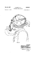
- FIG. 1 shows a side elevation of the mask with a portion of corrugated hose broken away
- range finder being shown as adapted to the mask.
- Fig. 2 is a section on line 2-2 of Fig. 1.
- Fig. 3 is a section on line 3-4 of Fig. 1.
- Fig. 4 is a front elevation of the mask.
- Fig. 5 is a rear elevation of the mask.
- Fig. 6 is a side elevation of the mask partly in section, the section taken on line 66 of Fig. 4, with the telephone equipment shown as worn with the mask.
- Fig. 7 is a front elevation of the spectacle frame, with the holder broken away.
- Fig. 8 is a side elevation, partly in section, of Fi 7.
- Fig. 9 is a front elevation oi the eyering.
- Fig. 10 is a side elevation, partly in section of F18. 9.
- Fig. 11 is a front elevation of the adapter.
- Fig. 12 is a side elevation partly in section of Fig. 11.
- Fig. 13 shows a section of the eyepiece before final securing oi the eyering.
- Fig. 14 shows a section of the eyepiece after final assembly of the eyering.
- Fig. 15 shows a section of the eyepiece after removing the rubber iacepiece material from in front of the lens.
- Fig. 16 is a section on line 16-46 of Fig. 4.
- Fig. 17 is a iront elevation, partly in section, of the angle tube portion of the mask.
- Fig. 18 is a central section thereof.
- Fig. 19 is an elevation of the plate used on the head harness.
- Fig. 20 is a front elevation, partly in section. of the head harness.
- Fig. 21 is a central section thereof.
- Fig. 22 is a section on line 22-22 of Fig. 20.
- Fig. 23 is a plan of the molded blank.
- Fig. 24 is a side elevation of the molded blank.
- Fig. 25 is a plan of the died out blank from which the iacepiece is formed.
- Fig. 26 is a section on line 26-26 of Fig. 25.
- Fig. 27 is a side elevation illustrating the plane of the eyepieces after the edges of the gores have been connected.
- Fig. 28 is a plan thereof.
- Fig. 29 is a section on line 23-28 of Fig. 27.
- Fig. 30 is a section on line 30-40 of Fig. 28.
- Fig. 31 is a section of the mold and faceblank, the latter taken on line til-3
- Fig. 32 is a sectional view illustrating the complementary mold sections in pressing position for homogeneously incorporating the sheets forming the inhalation tubes with the main portion of the faceblank, the iaceblank section taken on line 32-32 of Fig. 23.
- Fig. 33 is a section on line 33-33 oi Fig. 32.
- Fig. 34 is a section on line 34- of Fig. 32.
- Fig. 35 is a perspective view of core used with the molds.
- Fig. 36 is a section on line 38-36 oi Fig. 1.
- Fig. 3'7 is a similar section showing the parts where tension is applied to the head harness.
- the iacepiece is preferably made from a plurality of sheets oi uncured rubber plied together. Three sheets oi rubber have been found satisfactory, the sheets being of any desired composition which is impervious to liquid and gaseous vesicants and toxics. These sheets after assembly are molded to shape in special oi the mask at the lower edge.
- the rubber sheets II are placed in special molds l2 and 13 which are formed to shape the two eye portions M as shown in Fig. 31. Between the two eye portions It the rubber is bowed outward slightly to clear the bridge of the nose. As indicated by the shade lines in Figs. 23, 24 and 25, the central portion of the mask designated 15 is molded to form an outwardly extending portion which is at the maximum distance from the main portion
- the eye portions H are circular, and are positioned at an angle of about 40 to the plane oi the iacepiece.
- One of the novel features of this invention is the process of providing inlet tubes so positioned that incoming air impinges on the lenses to prevent iogging.
- these inlet tubes are integrally formed on the iacepiece by vulcanization in the special molds. From Figs. 23 to 25 it will be seen that the inlet tubes l6 slant upwardly toward the eye openings and are joined to the iacepiece at the bulges which support the lenses.
- the lower mold I! has recesses on its upper surface to accommodate removable cores I1, only one such core being shown.
- Each core ll (shown in Fig. 35) has a thin rectangular tongue I8 bent downwardly at I9 near its outer end, this bent-out end I! resting against the iacepiece near the eye opening when assembled.
- the two rectangular portions 18 Prior to assembly in the molds, the two rectangular portions 18 are wrapped in one or more sheets of uncured rubber of the desired thickness and placed as seen inFig. 32.
- the ends I! of tongues l8 pierce through the iacepiece as seen in Fig. 32.
- of mold I1 is positioned between the iacepiece II and the rubber forming the air inlet.
- the rubber is then vulcanized by heat treatment in the usual manner, and the iacepiece is shaped as seen in Figs. 23 and 24, with the eye portions protruding outwardly.
- the sheet rubber around tongue 18 of the core is vulcanized to the facepiece and these parts become integrally united.
- the molds may be heated by external heat, the rubber sheets being homogeneously united by the simultaneous heat and pressure.
- a wedge 22 is provided in the mold [3 which coacts with the rounded nose 23 of core 11.
- the core I! is withdrawn, leaving the inlet tubes [6 spaced from the facepiece a distance equal to spacer 2
- the tongue 18 forms the air passage and the bent portion I9 causes the incoming air to impinge directly upon the lenses.
- each inhalation tube I6 has a short tube 25, Fig. 2, inserted therein and the corrugated hose members leading from the canister are secured thereto.
- nipple 25 The purpose of nipple 25 is to reinforce the connection by preventing collapse of tube It when hose 92 is assembled thereon.
- the special molds shape the iacepiece so that the eye portions ll are flat disks on the smaller ends of truncated cones 30 which slant downwardly and inwardly toward the center of the facepiece.
- These truncated cones 30 are so orientedin the molded faceblank that the surface l4 of the eyepieces will assume a plane normal to the line of sight when the face blank is stitched, as seen in Fig. 27.
- the molded shape at and above the eyepieces is also such that contact with the forehead of the wearer is approximately at the superciliary ridges above the eyebrows. This prevents the facepiece from exerting painful pressure on thesupraorbital nerve.
- the molded shape at the eyepieces herein described further allows for positioning the observer's eyes at the proper distance from an optical instrument. The full field of vision of the instrument is permitted by this arrangement.
- the molds used '11 making the facepiece as herein described may be used for all sizes, the difference in the sizes being taken care of when the molded facepiece is cut as shown in Fig. 25.
- the tubes l6, one for each eyepiece, are arranged on the facepiece as seen in Fig. 27 at a suitable inclination for connection to the two corrugated hose members which are positioned below the wearer's ears as seen in Fig. 6 so as to avoid interference with a telephone head set.
- the molded facepiece after removal from the molds is cut or stamped out as seen in Fig. 25.
- Two upper tabs 26 are provided for connection to the harness straps 21 of the head pad, other straps 28 and 29 being connected as seen in Fig. 1.
- the lower edge of the facepiece is formed with a central curved gore 3 I, Fig. 25, with projections 32 on opposite sides thereof.
- the lower edge beyond projection 32 curves outwardly and upwardly as shown, both sides being of the same shape.
- the projections 32 are then stitched together, the stitching being carried back to the two sides, the gore 3
- the joint When thus stitched, the joint extends from the lower front central portion to the throat section and may be made gas tight by taping as seen at 34, Fig. 5.
- the facepiece thus made is given the shape shown in Figs. 27 to 30.
- the lower curved edges which are stitched provide a chin rest 34 and also a pocket 35 in which drainage such as saliva and perspiration collects. By tilting the head forward during use of the mask and blowing sharply, purging of this pocket is accomplished through the exhalation valve stem and valve port, hereinafter described.
- the lenses are secured to the facepiece.
- the glass lenses 36 are inserted from within the mask and are pressed forwardly against eye portions I4 within truncated cones 30, and separate threaded eye rings 31, Figs. 9 and 10, are slipped over the outside, see Fig. 13.
- Each eye ring 31 is then swaged over the lens, as seen in Fig. 14, thus firmly holding each lens in place on the facepiece, the rubber facepiece material being compressed at 38 and 39 to form a gas-tight joint around the lens.
- a suitable lubricant such as zinc stearate, is used to facilitate the swaging of the eyering over the lens.
- the rubber eye portions H are next cut away from in front of the lenses as seen in Fig. 15 by a rotary cutter lubricated with water.
- the spectacle frame shown in Figs. and 8 is then put in position, this frame including two rings 4
- the lugs 42 of each frame have right and left hand threads in openings through the same for the reception of an adjusting screw 43 provided with a knurled grip portion 44.
- the spectacle frame is secured-in assembled relation with the facepiece by retaining rings 45, Figs. 11, 12 and 16, which have annular flanges 46 for threaded engagement with the eye rings 31.
- ing rings 45 do not bind the spectacle frame against the eye rings 31. This arrangement allows the spectacle frame rings 4
- the adjusting screw 43 is provided with millimeter graduations 41, see Fig. 7, at one end which register with the edge of lug 42.
- the eyepieces can be adjusted to the correct interpupillary distance for the wearer by rotating the screw 43, so that binocular instruments may be used while wearing the mask. By advancing the screw one millimeter on scale 41, the eyepiece spacing is increased two millimeters.
- the facepiece is so molded that the eyepieces are at the minimum interpupillary distance without stretching or compressing the'facepiece, whereas in the maximum position the rubber facepiece is stretched between the eyepieces. Channeling or gaping of the facepiece periphery at the forehead and between the eyes is prevented by this stretching action to accommodate the maximum setting.
- Figs. 17 and 18 comprises a sheet metal cup having a plurality of openings 52 in its bottom. This cup is not uniform in depth, the rim being sloped as seen in Fig. 20 and the side wall near the bottom having rolled threads 53 formed thereon.
- an exhalation valve stem 54 Secured. to the long side of the angletube body 5
- This stem 54 has its outer wall slightly longer than the inner one and curved inward at 55 to follow the curvature of the face blank as seen in 18. This domed or curved portion 55 prevents cutting of the faceblank by the edge of stem 54 and prevents closing of the exhalation opening should the facepiece be compressed at this point while the mask is being worn.
- the exhalation valve comprises a bag 56 of soft pliable rubber provided with slits on its upper edges. Bag 56 is secured to stem 54 by first wrapping a strip of adhesive tape 51 around the upper end of the stem and turning it down over the rim thereof and then cementing the bag in place, and binding it with wire 58 covered with tape 59. Since the valve extends into and is protected by the cup member 5
- is secured to the cupped angle- From Fig. 16 it will be seen that the retain-- tube body at by clamp '02 which a threaded on the lower end of cup II, with a rubber gasket" positioned between the diaphragm and cup II.
- may be any suitable impervious material such as silk or linen fabric impregnated with a phenolic condensation product.
- the retaining clamp 82 has its bottom bowed inwardly to clear the diaphragm and allow vibrations of the same, the bottom having a plurality of openings 64.
- is secured to the facepiece by stretching the facepiece portion 33 over the angletube to the position shown in Fig. 18.
- Binding wire 65 and tape 66 make a gas tight joint and flange 61 and ridges 68 assist in making a secure joint.
- the harness consists of an oval shaped plate H, Figs. 19 to 22, cupped to flt the back of the head, with a sponge rubber pad 12 processed thereto, which cushions the canister from the wearers head.
- a central recess 13 in the plate and pad accommodates one part 14 of a separable fastener, the cooperating part of the fastener being secured to the canister.
- fastener I4 is upset over the edge of plate II, and a shield 15 is held in place by the fastener.
- the fastener On the outer side of plate I I, the fastener also holds in place a Spring plate 16 which resiliently presses against the canister when the same is secured to the head pad.
- the canister 11 shown in Figs. 1 and 6 is cylindrical and has the cooperating part of the separable fastener secured thereto midway of its length.
- the operating button 18 of the fastener is pressed inward and the canister 11 is pressed against the spring member 16 until the cooperating fasteners engage, when the button 18 is released.
- Spring member 18 holds the canister against twisting about the fastener and prevents accidental displacement.
- the head pad is connected to the facepiece by harness members including the non-elastic webbing 21, 28 and 29, Fi 1.
- the two webs 21 are connected across the head by web 8
- the webs 28 and 29 are arranged to be above and below the ears of a wearer. These webs engage buckles to adjust their eifective length and terminate in loops through which a spring member 84 passes.
- Straps 28 and 29 as attached to the facepiece by means of straps 86 improve the fit of the facepiece at the temple and cheek positions as more fully described in Monro Patent No. 1,395,760.
- Spring 84 comprises a closed loop of closely wound spring wire covered with a fabric sleeve which expands and contracts with the spring, as more fully described and claimed in patent to A. V. Motsinger, No. 1,942,442, January 9, 1934.
- the upper loops of spring 84 aresecured to webs 21 by the stitching 82 andrivet 88.
- the two lower portions of this spring extend downwardly and through an opening 85 in plate ll (seeFig'. 19) into the channel provided by the rim of shield ll.
- the spring passes around the fastener 14 and out ofopenings 86 and 81 of plate H and is looped to the lower webs 28.
- the spring 84 is one continuous element with four outwardly extending closed loops.
- each web or strap being given resiliency. by the fabric enclosed spring.
- the gas seal at the periphery of the facepiece is across the forehead approximately from temple to temple and from these temporal points down the sides of the face just in front of the ears and under the chin.
- the cylindrical canister 11 is provided with an air inlet 89, Fig. 1, extending lengthwise thereof.
- Two outlets are provided, one on each end of the cylinder, suitable air filtering and purifying means being interposed between the inlet and the outlets.
- Each outlet comprises a nipple 8 I, Fig. 3, to which is secured the hose 92 leading to the interior of the mask.
- Each of the two hose is of corrugated rubber having an integral molded elbow 93 at the canister end. As seen in Fig. 3, the hose must make a right angle turn to be secured to the canister.
- the integral elbow 93 simplifies this connection and the heavy molded construction prevents collapse of the elbow should this part be compressed while using the mask.
- Each hose 92 is slipped over the end of the inlet l6 and is secured thereto by binding wire and tape 94.
- this gas mask is designed essentially for use by personnel who must give commands or use optical instruments such as a range finder 96 shown by broken lines in Fig; l.
- the lenses 36 are positioned close to the wearers eyes and are normal to the line of vision, see Fig. 6, and are capable of ready adjustment to various interpupillary distances.
- the diaphragm is arranged in a natural position for transmitting speech, either directly or by a telephone as indicated in Fig. 6.
- the head harness and hose do not interfere with the use of a telephone head set.
- the canister is positioned out of the way and does not interfere with the movements of the head, yet may be readily removed for replacement by manipulation of the separable fastener.
- the incoming air is made to impinge on the lenses without the use of more or less complicated and troublesome deflectors.
- a facepiece having integral protuberances at the eye portions, lenses mounted in said protuberances. and means to adjust said lenses to .vary the interpupillary distance between said lenses.
- a facepiece of resilient material having integral protuberances at the eye portions. lenses mounted in said protuberances, and
- a facepiece of resilient material mounted therein, and means to adjust the interpupillary distance between said lenses,
- the lenses being maintained normal to the line of vision in all adjusted positions.
- a facepiece having an outwardly extending substantially cylindrical portion, means closing the inner end of said portion against ingress of air or gas, and an exhalation valve mounted within said cylindrical portion and protected thereby against injury.
- a facepiece having an outwardly extending substantially cylindrical portion, aspeaking diaphragm closing the inner end of said portion against ingress of air or gas, and an exhalation valve mounted within said cylindrical portion and protected thereby against injury.
- a facepiece havin an outwardly extending substantially cylindrical portion, means closing the inner end thereof, an exhalation valve extending upwardly within said cylindrical portion and in communication with the interior of the mask by a passageway adjacent the chin portion, and means to prevent closure of the passageway of the exhalation valve by pinching of the facepiece.
- a gas mask comprising a facepiece, a speaking diaphragm mounted therein adjacent the mouth of a wearer, glass lenses mounted normal to the line of sight of a wearer, and means to adjust the interpupillary distance between said lenses while maintaining their normal position.
Landscapes
- Health & Medical Sciences (AREA)
- Pulmonology (AREA)
- General Health & Medical Sciences (AREA)
- Business, Economics & Management (AREA)
- Emergency Management (AREA)
- Respiratory Apparatuses And Protective Means (AREA)
Description
Feb. 26, 1952 R. MONRO ET AL DIAPHRAGM OPTICAL GAS MASK ll Sheets-Sheet 1 Filed Oct. 16, 1935 Feb. 26, 1952 R. MONRO ETAL 2,586,851
DIAPHRAGM OPTICAL GAS MASK Filed Oct. 16. 1935 ll Sheets-Sheet 2 INVENTORS FHA 0 04 P19 MO/YPO ATTORNEY.
Feb. 26, 1952 Filed Oct. 16, 1935 ll fil w I 1 vii... J
I r 4/ n z H zzvmvzz'ms RANDOLPH MO/YPO ATTORNEY.
Feb. 26, 1952 R. MONRO ET AL DIAPHRAGM OPTICAL GAS MASK 11 Sheets-Sheet 4 Filed Oct. 16, 1935 ATTORNEY.
Feb. 26, 1952 MQNRO 2,586,851
DIAPHRAGM OPTICAL GAS MASK Filed Oct. 16, 1935 11 Sheets-Sheet 5 llll.
lllllllllllllllllllIIIll"llllllllllllllllll" BY k ATTORNEY.
Feb. 26, 1952 R. MONRO ETAL DIAPHRAGM OPTICAL GAS MASK 11 Sheets-Sheet 6 Filed 001,. 16, 1955 INVENTORS RflhOOLP/l MOIYIPO Vl/YG 6'. BROWN Feb. 26, 1952 MdNRQ ETAL 2,586,851
DIAPHRAGM OPTICAL GAS MASK l1 Sheets-Sheet 7 Filed Oct. 16, 1955 i MW f WW0 m m m MSW. & 5. E mg M ewgm a v v f a Q G 6. H
Feb. 26, 1952 MQNRQ 2,586,851
DIAPHRAGM OPTICAL GAS MASK Filed Oct. 16, 1935 11 Sheets-Sheet 8 ATTORNEY.
BY 001m m, A
Feb.'26, 1952 MONRO ET AL 2,586,851
DIAPHRAGM OPTICAL GAS MASK Filed Oct. 16, 1935 ll Sheets-Sheet 9 LNVL'NTORS H6; 26 BY omewa m,
ATTORNEY Feb. 26,
Filed Oct.
R. MONRO ET AL DIAPHRAGM OPTICAL GAS MASK 11 Sheets-Sheet 10 WM A ATTORNEY.
Patented F eb. 26, 1952 DIAPHRAGM OPTICAL GAS MASK Randolph Monro,
Edgewood, and Irving 0.
Brown, Baltimore, Md., and Clarence N. Hinkamp and Frank J. M. Parduhn, Washington, D. 0., assignors to United States of America as represented by the Secretary of War Application October 16, 1935, Serial No. 45,256
7 Claims.
(Granted under the act of March 3, 1883, as amended April 30, 1928; 370 0. G. 757) The invention described herein may be manufactured and used by or for the Government for governmental purposes, without the payment to us of any royalty thereon.
This invention relates in general to the apparatus for the protection of individuals from contaminated atmospheres, more particularly to a gas mask having small eyepieces adapted to fit against the eye socket of the wearer and having a diaphragm for voice transmission. Other features include a head pad with a spring type head harness for supporting a small canister on the back of the head, from which rubber tubes are so conducted that the inhaled air is caused to impinge directly on the interior surface of the lenses. The entire assembly is arranged to provide the requisite of comfort, especially at the eye and chin positions, also to facilitate the use of and avoid interference with the apparatus with which the wearer will come in contact particularly as regards the use of 20-ft. range finders and telephone head sets.
One object of this invention is to provide in the gas mask, comfortable eyepieces and which will permit the wearer of the mask to bring his eyes within the focal distance of optical instruments.
Another object of this invention is to fabricate the facepiece so as to provide a comfortable chin support and accommodate the angletube by means of a single seam at the chin position.
Another object of this invention is to so arrange the eyepiece portion in a semimolded facepiece that when the chin seam is assembled, the eyepieces will be in a plane normal to the line of sight of the wearer, without further manipulation of the facepiece or components.
Another object of this invention is to mold the inhalation tube stems integral with the portion of the facepiece material adjacent to the eyepieces, and in a position permitting the attachment of the corrugated hose tubes leading from the canister to fall beneath the wearers ears so as to avoid telephone head set interference.
Another object of this invention is to cause substantially all the inhaled air to impinge directly on the interior surfaces of the lenses, without the use of deflectors within the facepiece.
Another object of this invention is to provide a light-weight angletube so constructed that there is a minimum of parts. 3
Another object of this invention is to provide means for the wearer's voice to be readily heard, directly, over the telehone, or through voice tubes.
2 Another object of this invention is to cause the sound of the voice so transmitted to the interior of the facepiece to be reinforced by the synchronous vibration of a diaphragm and the exhalation valve located in front of it.
Another object of this invention is to protect the exhalation valve within the contour of the angletube without the use of special or projecting guards.
Another object of this invention is to provide an exhalation valve stem assembled within the contour of the angletube for simplifying the replacement of the exhalation valve.
Another object of this invention is to provide means for the drainage of saliva and perspiration of the facepiece through the exhalation valve.
Another object of the invention isto provide means for interlocking the lens and facepiece material without distortion of the latter.
Another object of this invention is to provide a threaded bridge for maintaining the eyepieces in a fixed plane and for adjusting the eyepieces to correspond with the interpupillary distance of the wearer.
Another object of this invention is to provide means in the angletube construction to improve.
voice transmission by stretching the diaphragm during assembly.
Another object of this invention is to provide a millimeter scale on the threaded bridge, to function similarly to a scale used on various range finding instruments for setting the eyepieces to correspond with the interpupillary distance of the operator.
Another object of this invention is to minimize kinking of the inhalation tubes by the use of corrugated hose.
Another object of this invention is to provide the corrugated hose with integrally molded elbows for attaching to the air purifying canister.
Another object of this invention is to provide a head pad for securely supporting the canister and to permit the quick detachment of latter for replacement.
Another object of this invention is to provide means in the head pad to accommodate a spring type head harness.
Another object of this invention is to provide small eyepieces so that the entire surfaces of the lenses can be impinged upon by the incoming air and so that the extraneous light can more readily be excluded when using optical instruments.
Other objects and advantages relate to the details of the process and the specific structure of the mask. all as will more fully appear from the Fig. 1 shows a side elevation of the mask with a portion of corrugated hose broken away, the
range finder being shown as adapted to the mask.
Fig. 2 is a section on line 2-2 of Fig. 1.
Fig. 3 is a section on line 3-4 of Fig. 1.
Fig. 4 is a front elevation of the mask.
Fig. 5 is a rear elevation of the mask.
Fig. 6 is a side elevation of the mask partly in section, the section taken on line 66 of Fig. 4, with the telephone equipment shown as worn with the mask.
Fig. 7 is a front elevation of the spectacle frame, with the holder broken away.
Fig. 8 is a side elevation, partly in section, of Fi 7.
Fig. 9 is a front elevation oi the eyering.
Fig. 10 is a side elevation, partly in section of F18. 9.
Fig. 11 is a front elevation of the adapter.
Fig. 12 is a side elevation partly in section of Fig. 11.
Fig. 13 shows a section of the eyepiece before final securing oi the eyering.
Fig. 14 shows a section of the eyepiece after final assembly of the eyering.
Fig. 15 shows a section of the eyepiece after removing the rubber iacepiece material from in front of the lens.
Fig. 16 is a section on line 16-46 of Fig. 4.
Fig. 17 is a iront elevation, partly in section, of the angle tube portion of the mask.
Fig. 18 is a central section thereof.
Fig. 19 is an elevation of the plate used on the head harness.
Fig. 20 is a front elevation, partly in section. of the head harness.
Fig. 21 is a central section thereof.
Fig. 22 is a section on line 22-22 of Fig. 20.
Fig. 23 is a plan of the molded blank.
Fig. 24 is a side elevation of the molded blank.
Fig. 25 is a plan of the died out blank from which the iacepiece is formed.
Fig. 26 is a section on line 26-26 of Fig. 25.
Fig. 27 is a side elevation illustrating the plane of the eyepieces after the edges of the gores have been connected.
Fig. 28 is a plan thereof.
Fig. 29 is a section on line 23-28 of Fig. 27.
Fig. 30 is a section on line 30-40 of Fig. 28.
Fig. 31 is a section of the mold and faceblank, the latter taken on line til-3| of Fig. 23.
Fig. 32 is a sectional view illustrating the complementary mold sections in pressing position for homogeneously incorporating the sheets forming the inhalation tubes with the main portion of the faceblank, the iaceblank section taken on line 32-32 of Fig. 23.
Fig. 33 is a section on line 33-33 oi Fig. 32.
Fig. 34 is a section on line 34- of Fig. 32.
Fig. 35 is a perspective view of core used with the molds.
Fig. 36 is a section on line 38-36 oi Fig. 1.
Fig. 3'7 is a similar section showing the parts where tension is applied to the head harness.
In order to make this invention clear, the fabrication oi the facepiece from the blank stock will be first described. The iacepiece is preferably made from a plurality of sheets oi uncured rubber plied together. Three sheets oi rubber have been found satisfactory, the sheets being of any desired composition which is impervious to liquid and gaseous vesicants and toxics. These sheets after assembly are molded to shape in special oi the mask at the lower edge.
molds in order to correctly position the eye portions and the inhalation tubes.
Referring to Figs. 31 to 35, the rubber sheets II are placed in special molds l2 and 13 which are formed to shape the two eye portions M as shown in Fig. 31. Between the two eye portions It the rubber is bowed outward slightly to clear the bridge of the nose. As indicated by the shade lines in Figs. 23, 24 and 25, the central portion of the mask designated 15 is molded to form an outwardly extending portion which is at the maximum distance from the main portion The eye portions H are circular, and are positioned at an angle of about 40 to the plane oi the iacepiece.
One of the novel features of this invention is the process of providing inlet tubes so positioned that incoming air impinges on the lenses to prevent iogging. By this invention these inlet tubes are integrally formed on the iacepiece by vulcanization in the special molds. From Figs. 23 to 25 it will be seen that the inlet tubes l6 slant upwardly toward the eye openings and are joined to the iacepiece at the bulges which support the lenses. As seen in Fig. 32, the lower mold I! has recesses on its upper surface to accommodate removable cores I1, only one such core being shown. Each core ll (shown in Fig. 35) has a thin rectangular tongue I8 bent downwardly at I9 near its outer end, this bent-out end I! resting against the iacepiece near the eye opening when assembled.
Prior to assembly in the molds, the two rectangular portions 18 are wrapped in one or more sheets of uncured rubber of the desired thickness and placed as seen inFig. 32. The ends I! of tongues l8 pierce through the iacepiece as seen in Fig. 32. The spacer leaf 2| of mold I1 is positioned between the iacepiece II and the rubber forming the air inlet. The rubber is then vulcanized by heat treatment in the usual manner, and the iacepiece is shaped as seen in Figs. 23 and 24, with the eye portions protruding outwardly. The sheet rubber around tongue 18 of the core is vulcanized to the facepiece and these parts become integrally united. The molds may be heated by external heat, the rubber sheets being homogeneously united by the simultaneous heat and pressure.
In order to assist in separating the molds, a wedge 22 is provided in the mold [3 which coacts with the rounded nose 23 of core 11. After the molds are separated, the core I! is withdrawn, leaving the inlet tubes [6 spaced from the facepiece a distance equal to spacer 2| of the core. The tongue 18 forms the air passage and the bent portion I9 causes the incoming air to impinge directly upon the lenses.
After removal from the molds, the iacepiece II is shaped as seen in Figs. 23 and 24 with the inlet tubes l5 spaced as seen in Fig. 26. The rubber of the iacepiece is then trimmed around the inner end of inlet tube 16, leaving the opening 24, Fig. 30, for entrance of air to the iacepiece. The end portion of each inhalation tube I6 has a short tube 25, Fig. 2, inserted therein and the corrugated hose members leading from the canister are secured thereto.
The purpose of nipple 25 is to reinforce the connection by preventing collapse of tube It when hose 92 is assembled thereon.
As seen from Fig. 24, the special molds shape the iacepiece so that the eye portions ll are flat disks on the smaller ends of truncated cones 30 which slant downwardly and inwardly toward the center of the facepiece. These truncated cones 30 are so orientedin the molded faceblank that the surface l4 of the eyepieces will assume a plane normal to the line of sight when the face blank is stitched, as seen in Fig. 27. The molded shape at and above the eyepieces is also such that contact with the forehead of the wearer is approximately at the superciliary ridges above the eyebrows. This prevents the facepiece from exerting painful pressure on thesupraorbital nerve.
The molded shape at the eyepieces herein described further allows for positioning the observer's eyes at the proper distance from an optical instrument. The full field of vision of the instrument is permitted by this arrangement.
In order to fit various sizes and shapes of faces. it is usually necessary to provide three or four sizes of facepiece. However, the molds used '11 making the facepiece as herein described may be used for all sizes, the difference in the sizes being taken care of when the molded facepiece is cut as shown in Fig. 25. The tubes l6, one for each eyepiece, are arranged on the facepiece as seen in Fig. 27 at a suitable inclination for connection to the two corrugated hose members which are positioned below the wearer's ears as seen in Fig. 6 so as to avoid interference with a telephone head set.
The molded facepiece after removal from the molds is cut or stamped out as seen in Fig. 25. Two upper tabs 26 are provided for connection to the harness straps 21 of the head pad, other straps 28 and 29 being connected as seen in Fig. 1. The lower edge of the facepiece is formed with a central curved gore 3 I, Fig. 25, with projections 32 on opposite sides thereof. The lower edge beyond projection 32 curves outwardly and upwardly as shown, both sides being of the same shape. The projections 32 are then stitched together, the stitching being carried back to the two sides, the gore 3| forming a substantially circular opening projecting forwardly, as seen at 33, Figs. 27 and 30.
When thus stitched, the joint extends from the lower front central portion to the throat section and may be made gas tight by taping as seen at 34, Fig. 5. The facepiece thus made is given the shape shown in Figs. 27 to 30. The lower curved edges which are stitched provide a chin rest 34 and also a pocket 35 in which drainage such as saliva and perspiration collects. By tilting the head forward during use of the mask and blowing sharply, purging of this pocket is accomplished through the exhalation valve stem and valve port, hereinafter described.
When using optical fire-control instruments on board ship, it is very advantageous to have a cushioning facial support such as this novel facepiece provides. During heavy firing or on other occasions when thereis heavy concussion, the observers eyes will be protected from injury by such instruments.
After stitching, the lenses are secured to the facepiece. Referring to Figs. 13 to 16, the glass lenses 36 are inserted from within the mask and are pressed forwardly against eye portions I4 within truncated cones 30, and separate threaded eye rings 31, Figs. 9 and 10, are slipped over the outside, see Fig. 13. Each eye ring 31 is then swaged over the lens, as seen in Fig. 14, thus firmly holding each lens in place on the facepiece, the rubber facepiece material being compressed at 38 and 39 to form a gas-tight joint around the lens. A suitable lubricant, such as zinc stearate, is used to facilitate the swaging of the eyering over the lens.
The rubber eye portions H are next cut away from in front of the lenses as seen in Fig. 15 by a rotary cutter lubricated with water. The spectacle frame shown in Figs. and 8 is then put in position, this frame including two rings 4| each having 2. lug 42. The lugs 42 of each frame have right and left hand threads in openings through the same for the reception of an adjusting screw 43 provided with a knurled grip portion 44.
The spectacle frame is secured-in assembled relation with the facepiece by retaining rings 45, Figs. 11, 12 and 16, which have annular flanges 46 for threaded engagement with the eye rings 31. ing rings 45 do not bind the spectacle frame against the eye rings 31. This arrangement allows the spectacle frame rings 4| to oscillate within their mounting as the adjusting screw 43 is operated back and forh, thereby avoiding any twisting strain on the facepiece which might cause it to gape at the periphery.
The adjusting screw 43 is provided with millimeter graduations 41, see Fig. 7, at one end which register with the edge of lug 42. The eyepieces can be adjusted to the correct interpupillary distance for the wearer by rotating the screw 43, so that binocular instruments may be used while wearing the mask. By advancing the screw one millimeter on scale 41, the eyepiece spacing is increased two millimeters. The facepiece is so molded that the eyepieces are at the minimum interpupillary distance without stretching or compressing the'facepiece, whereas in the maximum position the rubber facepiece is stretched between the eyepieces. Channeling or gaping of the facepiece periphery at the forehead and between the eyes is prevented by this stretching action to accommodate the maximum setting.
The assembly and insertion of the speaking diaphragm and the exhalation valve will now be described. These parts are mounted in the circular opening 33, Figs. 2'7 and 30. An angletube body 5| Figs. 17 and 18, comprises a sheet metal cup having a plurality of openings 52 in its bottom. This cup is not uniform in depth, the rim being sloped as seen in Fig. 20 and the side wall near the bottom having rolled threads 53 formed thereon. Secured. to the long side of the angletube body 5| and projecting into the cup is an exhalation valve stem 54 comprising a hollow sheet metal member of oval cross-section. This stem 54 has its outer wall slightly longer than the inner one and curved inward at 55 to follow the curvature of the face blank as seen in 18. This domed or curved portion 55 prevents cutting of the faceblank by the edge of stem 54 and prevents closing of the exhalation opening should the facepiece be compressed at this point while the mask is being worn.
The exhalation valve comprises a bag 56 of soft pliable rubber provided with slits on its upper edges. Bag 56 is secured to stem 54 by first wrapping a strip of adhesive tape 51 around the upper end of the stem and turning it down over the rim thereof and then cementing the bag in place, and binding it with wire 58 covered with tape 59. Since the valve extends into and is protected by the cup member 5|, the use of an additional valve guard is obviated and the entire valve is readily accessible for inspection and replacement.
The diagram 6| is secured to the cupped angle- From Fig. 16 it will be seen that the retain-- tube body at by clamp '02 which a threaded on the lower end of cup II, with a rubber gasket" positioned between the diaphragm and cup II. The diaphragm 6| may be any suitable impervious material such as silk or linen fabric impregnated with a phenolic condensation product. The retaining clamp 82 has its bottom bowed inwardly to clear the diaphragm and allow vibrations of the same, the bottom having a plurality of openings 64. By the assembly herein described, buckling and twisting of the diaphragm is avoided. It has been found in practice that glycerine applied to the faces of gasket 63 and diaphragm 6| acts as a lubricant and prevents drag of these parts during assembly.
From Fig. 18, it will be seen that the rubber gasket 63 is wider than the corresponding face of clamp 62, so that the inner portion of gasket 63 is not compressed when c1amp62 is tightened. This free portion of the gasket presses resiliently against the diaphragm GI and this stretchin action results in a tight and buckle-free diaphragm with improved voice transmission qualities.
The cupped angletube member 5| is secured to the facepiece by stretching the facepiece portion 33 over the angletube to the position shown in Fig. 18. Binding wire 65 and tape 66 make a gas tight joint and flange 61 and ridges 68 assist in making a secure joint.
The harness consists of an oval shaped plate H, Figs. 19 to 22, cupped to flt the back of the head, with a sponge rubber pad 12 processed thereto, which cushions the canister from the wearers head. A central recess 13 in the plate and pad accommodates one part 14 of a separable fastener, the cooperating part of the fastener being secured to the canister. As seen in Fig. 21, fastener I4 is upset over the edge of plate II, and a shield 15 is held in place by the fastener. Shield IE-comprises a flat cup having a curved rim or flange positioned with the closed side of the flange toward the head of the wearer.
On the outer side of plate I I, the fastener also holds in place a Spring plate 16 which resiliently presses against the canister when the same is secured to the head pad. The canister 11 shown in Figs. 1 and 6 is cylindrical and has the cooperating part of the separable fastener secured thereto midway of its length. To secure the canister to the head pad, the operating button 18 of the fastener is pressed inward and the canister 11 is pressed against the spring member 16 until the cooperating fasteners engage, when the button 18 is released. Spring member 18 holds the canister against twisting about the fastener and prevents accidental displacement.
The head pad is connected to the facepiece by harness members including the non-elastic webbing 21, 28 and 29, Fi 1. The two webs 21 are connected across the head by web 8| and are joined at their other ends by stitching 82 and rivet 83. As seen in Fig. 1, the webs 28 and 29 are arranged to be above and below the ears of a wearer. These webs engage buckles to adjust their eifective length and terminate in loops through which a spring member 84 passes.
An efllcient gas tight seal is secured by this harness construction, each web or strap being given resiliency. by the fabric enclosed spring. The gas seal at the periphery of the facepiece is across the forehead approximately from temple to temple and from these temporal points down the sides of the face just in front of the ears and under the chin.
The cylindrical canister 11 is provided with an air inlet 89, Fig. 1, extending lengthwise thereof. Two outlets are provided, one on each end of the cylinder, suitable air filtering and purifying means being interposed between the inlet and the outlets. Each outlet comprises a nipple 8 I, Fig. 3, to which is secured the hose 92 leading to the interior of the mask. I
Each of the two hose is of corrugated rubber having an integral molded elbow 93 at the canister end. As seen in Fig. 3, the hose must make a right angle turn to be secured to the canister. The integral elbow 93 simplifies this connection and the heavy molded construction prevents collapse of the elbow should this part be compressed while using the mask. Each hose 92 is slipped over the end of the inlet l6 and is secured thereto by binding wire and tape 94.
As previously indicated, this gas mask is designed essentially for use by personnel who must give commands or use optical instruments such as a range finder 96 shown by broken lines in Fig; l. The lenses 36 are positioned close to the wearers eyes and are normal to the line of vision, see Fig. 6, and are capable of ready adjustment to various interpupillary distances. The diaphragm is arranged in a natural position for transmitting speech, either directly or by a telephone as indicated in Fig. 6.
The head harness and hose do not interfere with the use of a telephone head set. The canister is positioned out of the way and does not interfere with the movements of the head, yet may be readily removed for replacement by manipulation of the separable fastener. The incoming air is made to impinge on the lenses without the use of more or less complicated and troublesome deflectors.
While we have shown and described the preferred embodiment of our invention, we wish it to be understood that we do not confine ourselves to the precise details of construction herein set forth by way of illustration, as it is apparent that many changes and variations may be made therein by those skilledin the art without departing from the spirit of the invention or exceeding the scope of the appended claims.
We claim:
1. In a gas mask, a facepiece having integral protuberances at the eye portions, lenses mounted in said protuberances. and means to adjust said lenses to .vary the interpupillary distance between said lenses.
2. In a gas mask, a facepiece of resilient material having integral protuberances at the eye portions. lenses mounted in said protuberances, and
means to adjust said lenses to vary the interpupillary distance between said lenses, the protuberances being so spaced that the facepiece is not stressed with the lenses at their minimum setting and the resilient facepiece may stretch to allow outward movement of the lenses.
3. In a gas mask, a facepiece of resilient material, lenses mounted therein, and means to adjust the interpupillary distance between said lenses,
the lenses being maintained normal to the line of vision in all adjusted positions.
4. In a gas mask, a facepiece having an outwardly extending substantially cylindrical portion, means closing the inner end of said portion against ingress of air or gas, and an exhalation valve mounted within said cylindrical portion and protected thereby against injury.
5. In a gas mask, a facepiece having an outwardly extending substantially cylindrical portion, aspeaking diaphragm closing the inner end of said portion against ingress of air or gas, and an exhalation valve mounted within said cylindrical portion and protected thereby against injury.
6. In a gas mask, a, facepiece havin an outwardly extending substantially cylindrical portion, means closing the inner end thereof, an exhalation valve extending upwardly within said cylindrical portion and in communication with the interior of the mask by a passageway adjacent the chin portion, and means to prevent closure of the passageway of the exhalation valve by pinching of the facepiece.
7. A gas mask comprising a facepiece, a speaking diaphragm mounted therein adjacent the mouth of a wearer, glass lenses mounted normal to the line of sight of a wearer, and means to adjust the interpupillary distance between said lenses while maintaining their normal position.
- RANDOLPH MONRO.
IRVING C. BROWN. CLARENCE N. HINKAMP. FRANK J. M. PARDUI-IN.
REFERENCES CITED The following references are of record in the file of this patent:
UNITED STATES PATENTS Number Name Date 488,190 Edison Dec. 20, 1892 844,952 Mirovitch Feb. 19, 1907 1,142,507 Edison June 8, 1915 1,177,025 Ellis Mar. 28, 1916 1,204,420 Edison Nov. 14, 1916 1,269,498 Parsons June 11, 1918 1,348,094 Del Re July 27, 1920 1,364,104 Geer Jan. 4, 1921 1,366,392 Lamb et al Jan. 25, 1921 1,395,836 Kops Nov. 1, 1921 1,395,837 Kops Nov. 1, 1921 1,526,793 King Feb. 17, 1925 1,730,227 McBride Oct. 1, 1929 1,762,695 Monro June 10, 1930 1,807,681 Baker June 2, 1931 1,863,073 Smythe June 14, 1932 1,960,544 Malcom May 29, 1934 2,036,850 Bullard Apr. 7, 1936 2,038,267 Bullard Apr. 21, 1936 2,039,234 Malcom Apr. 28, 1936 2,088,164 Dym July 27, 1937 FOREIGN PATENTS Number Country Date 85,167 Switzerland Dec. 31, 1935 275,354 Great Britain Aug. 11, 1927 297,890 Great Britain Nov. 21, 1923 312,594 Great Britain May 28, 1929 384,886 Great Britain Dec. 15, 1932 399,496 Great Britain Sept. 25, 1933 526,062 Germany June 1, 1931 531,452 Germany Aug. 10, 1931 610,343 Germany Mar. 8, 1935 793,806 France Nov. 23, 1935
Priority Applications (2)
| Application Number | Priority Date | Filing Date | Title |
|---|---|---|---|
| US45256A US2586851A (en) | 1935-10-16 | 1935-10-16 | Diaphragm optical gas mask |
| US173845A US2148431A (en) | 1935-10-16 | 1937-11-10 | Head harness and canister support |
Applications Claiming Priority (1)
| Application Number | Priority Date | Filing Date | Title |
|---|---|---|---|
| US45256A US2586851A (en) | 1935-10-16 | 1935-10-16 | Diaphragm optical gas mask |
Publications (1)
| Publication Number | Publication Date |
|---|---|
| US2586851A true US2586851A (en) | 1952-02-26 |
Family
ID=21936855
Family Applications (1)
| Application Number | Title | Priority Date | Filing Date |
|---|---|---|---|
| US45256A Expired - Lifetime US2586851A (en) | 1935-10-16 | 1935-10-16 | Diaphragm optical gas mask |
Country Status (1)
| Country | Link |
|---|---|
| US (1) | US2586851A (en) |
Cited By (22)
| Publication number | Priority date | Publication date | Assignee | Title |
|---|---|---|---|---|
| US2843115A (en) * | 1954-05-20 | 1958-07-15 | Aufricht Gustave | Combined spectacle frame and nasal clamp |
| US2952852A (en) * | 1956-05-07 | 1960-09-20 | Scott Aviation Corp | Face mask lens attaching means |
| EP0413861A1 (en) * | 1988-02-10 | 1991-02-27 | The Minister Of National Defence Of Her Majesty's Canadian Government | Speech transmitter |
| US5611644A (en) * | 1995-11-09 | 1997-03-18 | Johnson Worldwide Associates | Buckle for a diving mask |
| FR2812818A1 (en) * | 2000-08-10 | 2002-02-15 | Robert Schegerin | Aircraft pilot mask/helmet protection system includes helmet protecting head rear and sides, and breathing mask with air supply tube having air flow control and flexible section |
| US20050008183A1 (en) * | 2003-05-16 | 2005-01-13 | Greg Skillicorn | Electronic device mount for mask |
| US20110178585A1 (en) * | 2008-05-16 | 2011-07-21 | Biser Seth A | Thermal compress system and methods of using the same |
| US8784391B1 (en) * | 2010-11-18 | 2014-07-22 | Seth Biser | Therapeutic compress system and methods of use |
| US20190366133A1 (en) * | 2018-06-01 | 2019-12-05 | Avon Polymer Products Limited | Speech diaphragm module for a respirator mask |
| US10828452B2 (en) | 2014-09-16 | 2020-11-10 | Fisher & Paykel Healthcare Limited | Intramold headgear |
| US10874814B2 (en) | 2014-09-16 | 2020-12-29 | Fisher & Paykel Healthcare Limited | Headgear assemblies and interface assemblies with headgear |
| US11076983B2 (en) | 2008-05-16 | 2021-08-03 | Seth A. Biser | Thermal eye compress systems and methods of use |
| US11253668B2 (en) | 2016-03-16 | 2022-02-22 | Fisher & Paykel Healthcare Limited | Strap assembly, strap connector, headgear, headgear assembly, method of forming headgear, tubular connector, patient interface and method of joining straps |
| US11607518B2 (en) | 2016-03-16 | 2023-03-21 | Fisher & Paykel Healthcare Limited | Directional lock for interface headgear arrangement |
| US11648365B2 (en) | 2014-09-19 | 2023-05-16 | Fisher & Paykel Healthcare Limited | Headgear assemblies and interface assemblies with headgear |
| US11806452B2 (en) | 2012-08-08 | 2023-11-07 | Fisher & Paykel Healthcare Limited | Headgear for patient interface |
| US11819618B2 (en) | 2016-03-16 | 2023-11-21 | Fisher & Paykel Healthcare Limited | Intra-mould substrate |
| US11865263B2 (en) | 2009-12-23 | 2024-01-09 | Fisher & Paykel Healthcare Limited | Patient interface and headgear |
| US11878119B2 (en) | 2018-03-16 | 2024-01-23 | Fisher & Paykel Healthcare Limited | Headgear with lock disengagement mechanism |
| US11986595B2 (en) | 2017-12-21 | 2024-05-21 | Fisher & Paykel Healthcare Limited | Respiratory mask system |
| US12102764B2 (en) | 2017-06-26 | 2024-10-01 | Fisher & Paykel Healthcare Limited | Respiratory mask system |
| US12485245B2 (en) | 2013-04-24 | 2025-12-02 | Fisher & Paykel Healthcare Limited | Automatically adjusting headgear for patient interface |
Citations (31)
| Publication number | Priority date | Publication date | Assignee | Title |
|---|---|---|---|---|
| US488190A (en) * | 1892-12-20 | Phonograph-reproducer | ||
| US844952A (en) * | 1906-03-22 | 1907-02-19 | Elie Mirovitch | Eye-protector. |
| US1142507A (en) * | 1910-10-20 | 1915-06-08 | New Jersey Patent Co | Sound-recording apparatus. |
| US1177025A (en) * | 1911-04-26 | 1916-03-28 | James H Ellis | Diaphragm. |
| US1204420A (en) * | 1911-03-24 | 1916-11-14 | New Jersey Patent Co | Sound-box. |
| US1269498A (en) * | 1917-03-12 | 1918-06-11 | Harold K Parsons | Eye-protector. |
| CH85167A (en) * | 1915-03-01 | 1920-05-17 | Landis & Gyr Ag | Device for measuring the electrical current. |
| US1348094A (en) * | 1918-07-13 | 1920-07-27 | Re Domenico Del | Life-preserver helmet |
| US1364104A (en) * | 1919-01-23 | 1921-01-04 | Goodrich Co B F | Gas-mask |
| US1366392A (en) * | 1919-04-25 | 1921-01-25 | Arthur B Lamb | Respirator |
| US1395837A (en) * | 1919-04-25 | 1921-11-01 | Kops Waldemar | Gas-mask |
| US1395836A (en) * | 1919-04-24 | 1921-11-01 | Kops Waldemar | Gas-mask |
| GB297890A (en) * | 1922-09-20 | 1923-11-21 | John Ambrose Sadd | Improvements in or relating to respirators, gas-masks and other like apparatus |
| US1526793A (en) * | 1923-03-10 | 1925-02-17 | American Optical Corp | Goggles |
| GB275354A (en) * | 1926-05-21 | 1927-08-11 | Michael O Flanagan | Improvements in face masks |
| GB312594A (en) * | 1928-02-28 | 1929-05-28 | Fordyce Charles Jones | Improvements relating to respiratory gas masks or face pieces |
| US1730227A (en) * | 1923-03-31 | 1929-10-01 | Lewis M Mcbride | Gas mask |
| US1762695A (en) * | 1924-05-14 | 1930-06-10 | Monro Randolph | Gas mask |
| DE526062C (en) * | 1931-06-01 | Auergesellschaft Gmbh | Gas mask | |
| US1807681A (en) * | 1931-06-02 | A voluntary association | ||
| DE531452C (en) * | 1927-04-10 | 1931-08-10 | Auergesellschaft Gmbh | Gas mask |
| US1863073A (en) * | 1930-04-23 | 1932-06-14 | Bell Telephone Labor Inc | Method and means for tensioning and for mounting diaphragms |
| GB384886A (en) * | 1932-04-11 | 1932-12-15 | Schleich Friedrich | Gas mask conforming to the face |
| GB399496A (en) * | 1932-03-24 | 1933-09-25 | John Ambrose Sadd Major | Improvements in gas-masks, respirators and the like |
| US1960544A (en) * | 1932-06-06 | 1934-05-29 | Malcom Robert | Mask |
| DE610343C (en) * | 1935-03-08 | Bernh Draeger | Air supply pipe attached inside a gas mask | |
| FR793806A (en) * | 1934-08-18 | 1936-02-01 | Bartels & Rieger Hermet G M B | Protective masks against dust |
| US2036850A (en) * | 1932-01-02 | 1936-04-07 | Bullard Co | Mask |
| US2038267A (en) * | 1934-04-02 | 1936-04-21 | Bullard Co | Exhalation valve |
| US2039234A (en) * | 1934-01-29 | 1936-04-28 | Malcom Robert | Respiratory mask |
| US2088164A (en) * | 1934-10-08 | 1937-07-27 | Mine Safety Appliances Co | Breathing apparatus |
-
1935
- 1935-10-16 US US45256A patent/US2586851A/en not_active Expired - Lifetime
Patent Citations (31)
| Publication number | Priority date | Publication date | Assignee | Title |
|---|---|---|---|---|
| US488190A (en) * | 1892-12-20 | Phonograph-reproducer | ||
| US1807681A (en) * | 1931-06-02 | A voluntary association | ||
| DE526062C (en) * | 1931-06-01 | Auergesellschaft Gmbh | Gas mask | |
| DE610343C (en) * | 1935-03-08 | Bernh Draeger | Air supply pipe attached inside a gas mask | |
| US844952A (en) * | 1906-03-22 | 1907-02-19 | Elie Mirovitch | Eye-protector. |
| US1142507A (en) * | 1910-10-20 | 1915-06-08 | New Jersey Patent Co | Sound-recording apparatus. |
| US1204420A (en) * | 1911-03-24 | 1916-11-14 | New Jersey Patent Co | Sound-box. |
| US1177025A (en) * | 1911-04-26 | 1916-03-28 | James H Ellis | Diaphragm. |
| CH85167A (en) * | 1915-03-01 | 1920-05-17 | Landis & Gyr Ag | Device for measuring the electrical current. |
| US1269498A (en) * | 1917-03-12 | 1918-06-11 | Harold K Parsons | Eye-protector. |
| US1348094A (en) * | 1918-07-13 | 1920-07-27 | Re Domenico Del | Life-preserver helmet |
| US1364104A (en) * | 1919-01-23 | 1921-01-04 | Goodrich Co B F | Gas-mask |
| US1395836A (en) * | 1919-04-24 | 1921-11-01 | Kops Waldemar | Gas-mask |
| US1395837A (en) * | 1919-04-25 | 1921-11-01 | Kops Waldemar | Gas-mask |
| US1366392A (en) * | 1919-04-25 | 1921-01-25 | Arthur B Lamb | Respirator |
| GB297890A (en) * | 1922-09-20 | 1923-11-21 | John Ambrose Sadd | Improvements in or relating to respirators, gas-masks and other like apparatus |
| US1526793A (en) * | 1923-03-10 | 1925-02-17 | American Optical Corp | Goggles |
| US1730227A (en) * | 1923-03-31 | 1929-10-01 | Lewis M Mcbride | Gas mask |
| US1762695A (en) * | 1924-05-14 | 1930-06-10 | Monro Randolph | Gas mask |
| GB275354A (en) * | 1926-05-21 | 1927-08-11 | Michael O Flanagan | Improvements in face masks |
| DE531452C (en) * | 1927-04-10 | 1931-08-10 | Auergesellschaft Gmbh | Gas mask |
| GB312594A (en) * | 1928-02-28 | 1929-05-28 | Fordyce Charles Jones | Improvements relating to respiratory gas masks or face pieces |
| US1863073A (en) * | 1930-04-23 | 1932-06-14 | Bell Telephone Labor Inc | Method and means for tensioning and for mounting diaphragms |
| US2036850A (en) * | 1932-01-02 | 1936-04-07 | Bullard Co | Mask |
| GB399496A (en) * | 1932-03-24 | 1933-09-25 | John Ambrose Sadd Major | Improvements in gas-masks, respirators and the like |
| GB384886A (en) * | 1932-04-11 | 1932-12-15 | Schleich Friedrich | Gas mask conforming to the face |
| US1960544A (en) * | 1932-06-06 | 1934-05-29 | Malcom Robert | Mask |
| US2039234A (en) * | 1934-01-29 | 1936-04-28 | Malcom Robert | Respiratory mask |
| US2038267A (en) * | 1934-04-02 | 1936-04-21 | Bullard Co | Exhalation valve |
| FR793806A (en) * | 1934-08-18 | 1936-02-01 | Bartels & Rieger Hermet G M B | Protective masks against dust |
| US2088164A (en) * | 1934-10-08 | 1937-07-27 | Mine Safety Appliances Co | Breathing apparatus |
Cited By (35)
| Publication number | Priority date | Publication date | Assignee | Title |
|---|---|---|---|---|
| US2843115A (en) * | 1954-05-20 | 1958-07-15 | Aufricht Gustave | Combined spectacle frame and nasal clamp |
| US2952852A (en) * | 1956-05-07 | 1960-09-20 | Scott Aviation Corp | Face mask lens attaching means |
| EP0413861A1 (en) * | 1988-02-10 | 1991-02-27 | The Minister Of National Defence Of Her Majesty's Canadian Government | Speech transmitter |
| US5611644A (en) * | 1995-11-09 | 1997-03-18 | Johnson Worldwide Associates | Buckle for a diving mask |
| FR2812818A1 (en) * | 2000-08-10 | 2002-02-15 | Robert Schegerin | Aircraft pilot mask/helmet protection system includes helmet protecting head rear and sides, and breathing mask with air supply tube having air flow control and flexible section |
| US20050008183A1 (en) * | 2003-05-16 | 2005-01-13 | Greg Skillicorn | Electronic device mount for mask |
| US7302072B2 (en) * | 2003-05-16 | 2007-11-27 | Ultra Electronics Audiopack Inc. | Electronic device mount for mask |
| US9629746B1 (en) | 2008-05-16 | 2017-04-25 | Seth Biser | Therapeutic compress system and methods of use |
| US20110178585A1 (en) * | 2008-05-16 | 2011-07-21 | Biser Seth A | Thermal compress system and methods of using the same |
| US8636786B2 (en) | 2008-05-16 | 2014-01-28 | Seth A. Biser | Thermal compress system and methods of using the same |
| US11076983B2 (en) | 2008-05-16 | 2021-08-03 | Seth A. Biser | Thermal eye compress systems and methods of use |
| US11865263B2 (en) | 2009-12-23 | 2024-01-09 | Fisher & Paykel Healthcare Limited | Patient interface and headgear |
| US12128183B2 (en) | 2009-12-23 | 2024-10-29 | Fisher & Paykel Healthcare Limited | Patient interface and headgear |
| US8784391B1 (en) * | 2010-11-18 | 2014-07-22 | Seth Biser | Therapeutic compress system and methods of use |
| US11806452B2 (en) | 2012-08-08 | 2023-11-07 | Fisher & Paykel Healthcare Limited | Headgear for patient interface |
| US12226582B2 (en) | 2012-08-08 | 2025-02-18 | Fisher & Paykel Healthcare Limited | Headgear for patient interface |
| US12485245B2 (en) | 2013-04-24 | 2025-12-02 | Fisher & Paykel Healthcare Limited | Automatically adjusting headgear for patient interface |
| US10874814B2 (en) | 2014-09-16 | 2020-12-29 | Fisher & Paykel Healthcare Limited | Headgear assemblies and interface assemblies with headgear |
| US11813384B2 (en) | 2014-09-16 | 2023-11-14 | Fisher & Paykel Healthcare Limited | Intramold headgear |
| US10828452B2 (en) | 2014-09-16 | 2020-11-10 | Fisher & Paykel Healthcare Limited | Intramold headgear |
| US12102765B2 (en) | 2014-09-16 | 2024-10-01 | Fisher & Paykel Healthcare Limited | Headgear assemblies and interface assemblies with headgear |
| US11648365B2 (en) | 2014-09-19 | 2023-05-16 | Fisher & Paykel Healthcare Limited | Headgear assemblies and interface assemblies with headgear |
| US11607518B2 (en) | 2016-03-16 | 2023-03-21 | Fisher & Paykel Healthcare Limited | Directional lock for interface headgear arrangement |
| US11850365B2 (en) | 2016-03-16 | 2023-12-26 | Fisher & Paykel Healthcare Limited | Strap assembly, strap connector, headgear, headgear assembly, method of forming headgear, tubular connector, patient interface and method of joining straps |
| US11819618B2 (en) | 2016-03-16 | 2023-11-21 | Fisher & Paykel Healthcare Limited | Intra-mould substrate |
| US11819620B2 (en) | 2016-03-16 | 2023-11-21 | Fisher & Paykel Healthcare Limited | Directional lock for interface headgear arrangement |
| US12156968B2 (en) | 2016-03-16 | 2024-12-03 | Fisher & Paykel Healthcare Limited | Directional lock for interface headgear arrangement |
| US11253668B2 (en) | 2016-03-16 | 2022-02-22 | Fisher & Paykel Healthcare Limited | Strap assembly, strap connector, headgear, headgear assembly, method of forming headgear, tubular connector, patient interface and method of joining straps |
| US12521512B2 (en) | 2016-03-16 | 2026-01-13 | Fisher & Paykel Healthcare Limited | Intra-mould substrate |
| US12102764B2 (en) | 2017-06-26 | 2024-10-01 | Fisher & Paykel Healthcare Limited | Respiratory mask system |
| US11986595B2 (en) | 2017-12-21 | 2024-05-21 | Fisher & Paykel Healthcare Limited | Respiratory mask system |
| US12434030B2 (en) | 2017-12-21 | 2025-10-07 | Fisher & Paykel Healthcare Limited | Respiratory mask system |
| US11878119B2 (en) | 2018-03-16 | 2024-01-23 | Fisher & Paykel Healthcare Limited | Headgear with lock disengagement mechanism |
| US12042675B2 (en) * | 2018-06-01 | 2024-07-23 | Avon Polymer Products Limited | Speech diaphragm module for a respirator mask |
| US20190366133A1 (en) * | 2018-06-01 | 2019-12-05 | Avon Polymer Products Limited | Speech diaphragm module for a respirator mask |
Similar Documents
| Publication | Publication Date | Title |
|---|---|---|
| US2586851A (en) | Diaphragm optical gas mask | |
| US2504524A (en) | Safety spectacle bridge lift | |
| US5080092A (en) | Protective mask | |
| US2359506A (en) | Fully molded gas mask facepiece | |
| US2903700A (en) | Eye shield | |
| US2935985A (en) | Airtight helmet | |
| US3239842A (en) | Safety helmet | |
| KR950006854B1 (en) | Visual equipment support method and head gear | |
| US6701535B2 (en) | Adjustment mechanism for a headmount apparatus | |
| US2810386A (en) | Oxygen masks embodying means for ventilating goggles | |
| US2369829A (en) | Camera support | |
| US2381568A (en) | Gas mask | |
| US20150216250A1 (en) | Protective garment | |
| US2671445A (en) | Gas mask and helmet | |
| US6318369B1 (en) | Eye ear and respiration protection apparatus | |
| US3052887A (en) | Face protective devices | |
| US2300912A (en) | Respiratory device | |
| US2810385A (en) | Means for supporting apparatus on the head | |
| KR20180058604A (en) | Breathing frame of mask with holder device | |
| US1364104A (en) | Gas-mask | |
| KR20170059722A (en) | Breathing frame of mask | |
| US2387851A (en) | Goggles | |
| US2465973A (en) | High elevation mask | |
| US3026522A (en) | Diving helmet | |
| US2710965A (en) | Headgear for skullguards |