US2527615A - Fuel injection system for internalcombustion engines - Google Patents
Fuel injection system for internalcombustion engines Download PDFInfo
- Publication number
- US2527615A US2527615A US584115A US58411545A US2527615A US 2527615 A US2527615 A US 2527615A US 584115 A US584115 A US 584115A US 58411545 A US58411545 A US 58411545A US 2527615 A US2527615 A US 2527615A
- Authority
- US
- United States
- Prior art keywords
- plunger
- valve
- fuel
- ports
- pressure
- Prior art date
- Legal status (The legal status is an assumption and is not a legal conclusion. Google has not performed a legal analysis and makes no representation as to the accuracy of the status listed.)
- Expired - Lifetime
Links
Images


Classifications
-
- F—MECHANICAL ENGINEERING; LIGHTING; HEATING; WEAPONS; BLASTING
- F02—COMBUSTION ENGINES; HOT-GAS OR COMBUSTION-PRODUCT ENGINE PLANTS
- F02M—SUPPLYING COMBUSTION ENGINES IN GENERAL WITH COMBUSTIBLE MIXTURES OR CONSTITUENTS THEREOF
- F02M59/00—Pumps specially adapted for fuel-injection and not provided for in groups F02M39/00 -F02M57/00, e.g. rotary cylinder-block type of pumps
-
- F—MECHANICAL ENGINEERING; LIGHTING; HEATING; WEAPONS; BLASTING
- F02—COMBUSTION ENGINES; HOT-GAS OR COMBUSTION-PRODUCT ENGINE PLANTS
- F02M—SUPPLYING COMBUSTION ENGINES IN GENERAL WITH COMBUSTIBLE MIXTURES OR CONSTITUENTS THEREOF
- F02M69/00—Low-pressure fuel-injection apparatus ; Apparatus with both continuous and intermittent injection; Apparatus injecting different types of fuel
- F02M69/46—Details, component parts or accessories not provided for in, or of interest apart from, the apparatus covered by groups F02M69/02 - F02M69/44
- F02M69/50—Arrangement of fuel distributors, e.g. with means for supplying equal portion of metered fuel to injectors
-
- F—MECHANICAL ENGINEERING; LIGHTING; HEATING; WEAPONS; BLASTING
- F02—COMBUSTION ENGINES; HOT-GAS OR COMBUSTION-PRODUCT ENGINE PLANTS
- F02M—SUPPLYING COMBUSTION ENGINES IN GENERAL WITH COMBUSTIBLE MIXTURES OR CONSTITUENTS THEREOF
- F02M2700/00—Supplying, feeding or preparing air, fuel, fuel air mixtures or auxiliary fluids for a combustion engine; Use of exhaust gas; Compressors for piston engines
- F02M2700/05—Miscellaneous constructional elements; Leakage detection
- F02M2700/055—Fuel distribution among injection nozzles
Definitions
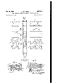
- FUEL INJECTION SYSTEM FOR INTERNAL-COLBUSTION ENGINES Filed March 22, 1945 E. S. L. BEALE Oct. 31, 1950 4 Sheets-Sheet 4 Patented Oct.
- An object of this invention is to provide an improved system of this kind which ensures a rapid rise and fall of fuel pressure on the injector at the beginning and end of the injection period.
- Another object is to provide such a system which is especially suitable for use with internalcombustion engines of the free-piston type.
- the motion of the piston, or more commonly of two synchronised oppositely moving pistons is not completely constrained by a continuously rotating crank, and in consequence the primary moving parts of the engine come to rest at the inner dead point so that it is diflicult to .provide a drive for fuel-injection means which will maintain the injection period over the inner dead point.
- Another object is to render the quantity of fuel injected per cycle independent of variation in engine speed.
- Another object is to reduce variation in the quantity of fuel injected per cycle in consequence of variation in pressure of the source of fuel.
- Another object is to provide a system of the kind specified which is particularly suitable for use on engines where a mechanical drive for the timing valv cannot conveniently be arranged near to the injector or injectors, so that pipes of substantial length are required to transmit liquid pressure pulsations.
- Another object is to provide in a system of the kind specified one valve which is actuated by the engine and which supplies a fuel duct with a succession of fluid pressure pulses having a frequency equal to the cyclic frequency of the engine, and a second valve capable, in response to application to it of this succession of pulses, of supplying a fuel-injection nozzle with a corresponding succession of accurately metered fuel-charges, the time-intervals between the receipt by the second valve of the fronts of the pressur pulses and the beginning of the corresponding injection periods being substantially uniform.
- Fig. 1 is a schematic diagram showing the principal elements oi the apparatus and the connecting pipes, which are marked with arrows showing the directions of flow through them.
- Fig. 2 is a diagrammatic section of a flash valve associated with a disabling and timing valve.
- Figs. 3A, 3B and 30 show details of the plungers and ports of the flash and timing valves:
- Fig. 3A is an elevation of the plunger, which is of the same design in both valves (except for a slight difference which will be described hereinafter);
- Fig. 3B is a development of the plunger edges and ports of the disabling and timing valve;
- Fig. 3C is a corresponding development of the flash valve.
- Fig. 4 is a section through the barrel of the disabling and timing valve, showing the actual shape of passages connecting a pair of diametricallyopposed ports.
- Fig. 5 is a section through the barrel of the flash valve and through an associated pair of delivery valves.
- Fig. 6 is a schematic diagram or a modified system.
- Fig. 'l is a diagrammatic section of one of the valves appearing in Fig. 6, and
- Fig. 8 shows a modification in the flash valve appearing in Fig. 2.
- the source of fuel under pressure is an accumulator vessel 20 provided with a relief valve 2i and charged by a supply pump 22 driven by an eccentric 23 on the pistonsynchronising mechanism of the engine and drawing fuel from a tank l9.
- an additional pump 24 is provided, which is capable of charging the accumulator 20 to working pressure with a single stroke and I which is operated by a piston 25 in a cylinder 26 connected to a fluid pressure line 21 which is en ergised as a preliminary to the starting operation.
- This fluid pressure line may be the compressed air supply line to the starting air chambers usually provided on the engine.
- a piston valve hereinafter termed the flash valve, is denoted generally by reference 28; this valve is associated with a second valve 29, which is also a piston valve, and which will be termed the "timing valve.
- timing valve 29 The function of the timing valve 29 is to set in motion the flash valve 28 which actually controls the injection, and to act as a disabling valve to prevent a second injection on the return stroke of the flash valve.
- the timing-valve plunger 30 (Fig. 2) is driven off the free-piston synchronising mechanism by a cam 3
- the timing-valve plunger 30 is provided with a double-start helical groove 34 co-operating with a pair of diametrically opposed supply ports 85 (Fig.
- valve plunger is rotatable about its axis by means of a slidable rack 31 engaging a pinion 38 co-axial with and coupled to the plunger 38 by a cross piece 39 rigid with the plunger and engaged in slots 38 in a tubular boss of the pinion 38.
- the rack 31 is operated by an automatic controller 48 (Fig. 1) acting through a bell-crank lever 4
- has a pivot 43 eccentrically mounted on a control shaft 44 which is rotatable by a control lever 45 to give a hand adjustment of the timing.
- the automatic controller 40 may be an inner dead point follower as described in our Patent 2,470,231.
- Such a device is indicated diagrammatically in Fig. 1.
- it may be a device responsive to the working pressure of the gas-generator.
- both an inner dead point follower and a device responsive to working pressure may actuate the rack 31 through means which combine the control influences of those two devices.
- the supply ports 35 are in uninterrupted communication through a pipe l8 with the accumulator 20 and the release ports 35 communicate with a spill vessel 45 through a spill passage 41 in the flash valve 28 and a pipe 48.
- the ports are so placed that at the beginning of the instroke of the timing valve plunger 30, the release ports 35 open into the helical groove 34 While the supply ports 35 are sealed by the plunger.
- Fig. 3B where the plunger 38 appears in the position giving maximum advance of the timing.
- the range of angular adjustment effected by the timing rack 31 is indicated in Fig. 33 as 113, the position of the helical groove 34 corresponding to full retard being denoted by dotted lines.
- the lift of the plunger is denoted by I.
- the supply ports 35 are uncovered by the helical groove 34 and the release ports 35 are masked by the valve plunger.
- the helical groove 34 is in constant communication, by means of a longitudinal hol 49 in the valve plunger, with an annular groove in the plunger, which at all times communicates with a transfer passage 5
- the plunger 52 of the flash-valve 28 (Fig. 3C) has an annular groove 53 co-operating with a pair of diametrically opposed delivery ports 54 and in constant communication, by means of a longitudinal hole 55 in the valve plunger, with a double-start helical groove 55.
- This groove cooperates with a pair of diametrically opposed cutoff ports 51 opening out of the transfer passage 5
- This plunger 52 is rotatable about it axis by a second rack-and-pinion mechanism 50, 6
- ports and grooves are so placd that, when the flash-valve plunger 52 is at the beginning of its active stroke, in which it appears in Fig. 30. the spill ports 58 and the delivery ports 54 are masked and the cut-oil. ports 51 are open to the helical groove 55.
- the annular groove 53 uncovers the delivery ports 54, and, as the fuel supply pressure is already present in the grooves 55 and 53, having been admitted via the timing valve 25, the transfer passage 5
- the delivery ports 54 communicate with four injectors 54 (Fig. 1) through non-return valves 65 of the unloading type.
- the delivery pipe branches to feed two valves 55, as shown in Fig. 5, and each of these valves supplies two of the injectors.
- the valves 55 are of known type having a poppet head 65 rigid with a piston 51 and urged onto a seating 58 by a spring 89.
- the piston is slidable to a limited extent in a bore in the valve body, and restricted delivery passages 10 are drilled through the piston head. While oil is being delivered by the valve the piston is held by the oil pressure difference, due to the restricted passages 10, against a stop 1 I.
- the spring 69 returns the piston 51 which, before the popp t valve has seated, will have displaced enough oil from the injectors to ensure that the oil pressure in them falls to a value such that there is no risk of dribbling, or of secondary injection.
- the fiash valve plunger 52 is moved through its active stroke by a hydraulic lifting plunger 12 bearing against a thimble tappet 13 operating as a piston in a cylindrical bore 14 in the flash valve body.
- This tappet is engaged by a spring plate 15 which is engaged with or rotatable on the flanged end of the plunger 52 and loaded by a compression spring 15.
- An air port 11 extends from the inner end to near the outer end of the bore 14. and the part of this bore beyond the outer end of the air port forms an air buffer space, a narrow slot 18 serving as a restricted air vent for this space.
- the plunger 12 is slidable in a cylinder 19 which communicates by a bore and a pipe 8
- the rate of movement of the flash-valve plunger 52 through its active stroke is controlled by a hydraulic dash pot, which comes into operation when the end face 82 of the plunger overruns a pair of diametrically opposed suction ports 53 and traps fuel in a buffer chamber 84 which is provided with an adjustable leak 85.
- the suction ports 83 and the leak 55 communicate with the spill passage 41 and are arranged to be always flooded wtih oil.
- References 85, 81, 88 and 8! denote passages for conveying leaking oil to the spill passage 41.
- the pressure in the buiier chamber 84 is in fixed ratio to the supply pressure determined by the ratio of the areas of the lifting plunger 12 and of the valve plunger 52.
- the supply pressure is 10,000 lb. per sq. in. and the lifting plunger area is one-quarter of the bufier area
- the pressure in the buffer chamber will be 2,500 lb. per sq. in. and fuel will escape through the buffer delivery port at a constant rate determined by the area of this port and the supply pressure.
- friction and inertia effects are insignificant.
- a steady velocity of the flash-valve plunger is rapidly reached and maintained till very near the end of the active stroke, when this plunger begins to close the buffer delivery port 85 and cushions the valve plunger as it reaches a, top stop 99.
- This arrangement provides a substantial degree of automatic compensation for variation in supply pressure. If this pressure falls for example, the rate of flow through the injection nozzles is reduced when the rate of flow through the buffer delivery port 85 decreases. The duration of injection is therefore correspondingly increased, with the result that more or less the same quantity of fuel is injected.
- the flash-valve plunger 52 After the end of injection the flash-valve plunger 52 remains against its top stop 9! until the timing valve 29 makes its return stroke, some time after the engine pistons have passed their inner dead point, and in so doing releases the pressure in the transfer passage 5
- the flash valve plunger is now free to return, in readiness for the next cycle, under the influence of its spring It to its bottom position which it enters under control of the pneumatic cushion ll, I4, TI, ll.
- the flash valve plunger cannot make its return stroke until the fuel pressure in the transfer passage 5i has been released, no pressure is available at the cut-off ports 51 of the flash valve to produce a second injection as the flash-valve plunger makes its return stroke.
- the spring 16 of the flash valve must be strong enough to draw a vacuum in the buffer chamber 84 and give the plungers 52 and I2 enough acceleration to bring them to the bottom position in good time for the next cycle.
- the buffer suction ports 83 are uncovered, oil is sucked into the bufier chamber 84 from the spill passage 41 through these ports.
- the flash-valve spring may be light and the suction-port area moderate.
- the rate of rise of oil pressure applied to the injectors at the beginning of the injection period is controlled by giving the annular passage 53 of the flash-valve plunger a shallow depth adjoining the edge which opens the delivery ports 54 and progressively increasing the end. This is the only difference between this plunger and the timing valve plunger.
- the release ports 30 of the timing valve II open to the spill pipe Al, through a restriction 8
- the restriction must not be so small as to retard unduly the return stroke of the' flash-valve plunger.
- a restriction 59 may also be provided between the spill ports '58 and the spill pasage 41 in order to prevent cavitation in the passage between the delivery ports 54 and the unloading valves 65 when this passage is relatively long.
- the spill vessel 46 is placed close to the valves 2! and 29 and is arranged to damp pulsations in the spilled oil, which might lead to excessive pressures and erratic operation if allowed to persist in along spill pipe. Accordingly inside the vessel 48 is placed a hermetically-sealed corrugated bellows of oil-resistant rubber and containing air or other gas.
- the device thus operates in the same way as an air vessel, except that there is no risk of loss of air due to violent pulsations in the fluid pressure.
- Fig. 6 which relates to a free-piston engine of the opposedpiston type having four injectors.
- Two of these injectors, A, on one side of the engine, are supplied respectively through two delivery valves 65A from a flash valve 28 A, and the other two injectors, MB, on the other side of the engine, are supplied respectively through two delivery valves "B from a flash valve 283.
- the flash valves 20A and 28B are associated respectively with two similar slave timing valves 29A and 29B and with accumulators 20A and 2013.
- a master timing valve 29 substantially similar to the timing valve 20 shown in Fig. 2, is operated by a cam Il fast on the pinion shaft 98 of the piston synchronising gear of the engine, which is of the known rack-and-pinion type. Oil at a pressure of say 40 lb. per sq. in. is supplied at it to the master timing valve 29 which therefore alternately applies this relay oil pressure to, and releases it from, branch pipes 92A and 92B of equal length leading respectively to the slave timing valves 29A and 293.
- Fig. 7 shows the slave timing valve 293 as an example.
- a spring-biased piston 94 operating in a hydraulic relay cylinder )5 operates, when relay oil pressure is applied to the pipe 828, to raise the poppet valve 93 through the agency of a push rod 96.
- the pipes 92A and 92B between the master timing valve 29 and the slave timing valves 29A and 29B, are relatively long but the function of the master timing valve is merely to cause the slave timing. valves to lift at the correct instant and to stay open until injection has finished.
- the time delay due to the length of the pipes "A and 923 can be easily allowed for by advancdepth of the annular passage towards its other 7 ing the timing of the master timing valve.
- a piston-type timing valve by a valve of a type other than a piston valve, e. g. a poppet valve, does not affect the injection characteristics, which are determined by the flash valve, and the timing valve may be driven by means other than those hereinbefore described.
- the timing valve may be actuated either by a small gas motor energised by th pressure in the engine cylinder, such as is described in the specification of Patent No. 2,351,414 or by an inertia gear as described in patent application Serial No. 478,-
- a land 56 on the valve plunger 52 has two double-start helical ends cooperating with a pair of spill ports 58 and a pair of cut-off ports 51
- the groove 53 extends from the land 58 to the plunger head and communicates through the hole 55 with a spill groove Hill.
- the bottom edge of the head of the flash-valve plunger may be shaped as a double-start helix Hll of relatively flne pitch co-operating with the delivery ports 54 so that the timing of the beginning of injection varies with the quantity of fuel injected.
- the helical edge may be of such a hand that as the fuel quantity is increased injection begins earlier.
- the preferred resilient driving means for the flash valve are fluid pressure operated, such means may be replaced by any other non-positive driving means, e. g. spring pressure. giving a more or less steady driving eilort irrespective of variation in engine speed.
- a fuel-injection system for an internalcombustion engine and including a source of fuel at high pressure, an injector, a piston valve for controlling a duct connecting said source to said injector and including a plunger slidable in a barrel havinga delivery port communicating with said injector and a spill port, means for reciprocating said plunger at the cyclical frequency of the engine, said ports being so located in relation to land edges of said plunger that said ports are respectively uncovered by said edges during the active stroke of said plunger for the purpose of determining the beginning and the end of the injection period while said plunger is'remote from either end of its stroke and therefore moving at a relatively high velocity, and a second valve associated with said duct for preventing a second injection on the return stroke of said plunger.
- An internal-combustion engine associated with a gas pressure line, which is energised as a preliminary to starting the engine, and having a fuel-injection system including an accumulator for fuel, a pump driven by said engine and connected to keep said accumulator charged, an additional plunger pump capable at a single delivery stroke of raising the pressure in said accumulator to its working value, a gas pressure motor having a piston coupled to the auxiliary pump plunger and subjected to the pressure in said line so as to cause said plunger to execute a delivery stroke in response to energizing of said line, an injector, at least one piston valve for controlling a duct connecting said accumulator to said injector, and means for operating said piston valve at the cyclical frequency of the engine.
- a fuel-injection system for an internalcombustion engine and including a source of fuel at high pressure, an injector, a piston valve for controlling a duct connecting said source to said injector and including a plunger slidable in a barrel having a delivery port communicating with said injector and a spill port, means for reciprocating said plunger at the cyclical frequency of the engine, said ports being so located in relation to land edges of said plunger that said ports are respectively uncovered by said edges during the active stroke of said plunger for the purpose of determining the beginning and the end of the injection period while said plunger is remote from either end of its stroke and therefore moving at a relatively high velocity, and a shut-off valve also controlling said duct in series with said piston valve, and engineoperated means for keeping said shut-oil valve closed during the return stroke of said plunger.
- a fuel-injection system for an internalcombustion engine and including a source of fuel at injection pressure, an injector communicating with said source by a duct including at least one piston valve capable in the course of a single active stroke of establishing and interrupting such communication and thereby beginning and ending the injection period, said valve including a barrel, a plunger slidable in said barrel, resilient driving means for displacing said plunger on its active stroke, engine-operated means for cyclically bringing said driving means into operation and a hydraulic dash-pot device for controlling the velocity of said plunger on its active stroke so that the quantity of fuel injected per cycle is substantially uninfluenced by variation in engine speed.
- said resilient driving means are a fluid-pressure motor operable by the fluid pressure of the fuel as supplied from said source, and said engineoperated means control the admission of fuel from said source to said motor.
- Apparatus as claimed in claim 4 including a spring for returning said plunger and a buffer for cushioning said plunger at the end of its return stroke.
- the said one valve is of the piston type including a plunger slidable in a, barrel, said plunger being associated with fluid pressure operated means capable under the pressure of fuel as supplied from said source of displacing said plunger on its active stroke,
- timing valve is provided with control means operable for advancing and retarding the timing of the alternative connections which it makes.
- timing valve is also of the piston type ineluding a plunger slidable in a barrel having a delivery port communicating with said fluid pressure operated means and with said first-mentioned piston valve, said timing-valve barrel also having a spill port and said timing-valve plunger having oblique land edges cooperating with said ports, and wherein control means are operable to impart relative angular displacement to the plunger and barrel of said timing valve for the purpose of advancing and retarding the timing of the alternative connections made by the said timing valve.
- timing valve is also of the piston type, including a plunger and a barrel, said plunger having a multi-start helical edge cooperating with a corresponding number of ports uniformly distributed around its barrel, and wherein control means are operable to impart relative angular displacement to the plunger and barrel of said timing valve about their axis for the purpose of advancing and retarding the timing of the alternative connections made by said last-montioned valve.
- a fuel-injection system for an internalcombustion engine including a source of fuel at high pressure, an injector, a, piston valve for controlling a duct connecting said source to said injector and including a plunger slidable in a barrel having a delivery port leading to said injector, a spill port and a cut-off port which serves also as an inlet port, means for reciprocating said plunger at the cyclical frequency of the engine, said ports being so located in relation to land edges of said plunger that said edges overrun said ports while said plunger is remote from either end position and therefore moving at relatively high velocity and thatsaid plunger in course of its active stroke opens said delivery port while said spill port is closed and said cut-oil port is open, and thereafter closes said cut-off port and opens said spill port while the delivery port is still open, and a second valve associated with said duct for preventing a second injection on the return strike of said plunger.
- a fuel-injection system for an internalcombustion engine and including a source of fuel at high pressure, an injector, a piston valve for controlling a duct connecting said source to said injector and including a plunger slidable in a barrel having a delivery port leading to said injector, a spill port and a cut-off port which serves also as an inlet port, means for reciprocating said plunger at the cyclical frequency of the engine, the land edges of said plunger that cooperate with said cut-off and spill ports being oblique and said ports being so located in relation to the land edges of said plunger that said edges overrun said ports while said plunger is remote from either end position and therefore moving at relatively high velocity and that said plunger in course of its active stroke opens said delivery port while said spill port is closed and said cutofl port is open, and thereafter closes said cut-oil port and opens said spill port while said delivery port is still open, fuel-quantity control means for imparting relative angular displacement to said barrel and said plunger about their axes, and a second valve
- a fuel-injection system for an internalcombustion engine including a source of fuel at high pressure, an injector, a piston valve for controlling a duct connecting said source to said injector and including a plunger slidable in a ported barrel and having an edge cooperating with at least one delivery port communicating with the injector, said plunger having a multi-- start helical edge cooperating with a corresponding number of cut-off ports which communicate with said source and which are uniformly distributed around said barrel and a multi-start helical edge cooperating with a corresponding number of spill ports which communicate with a spill duct and which are uniformly distributed around said barrel, said ports being so located in relation to said edges that said edges overrun said ports while said plunger is remote from either end position and therefore moving at relatively high velocity, fuel-quantity control means for imparting relative angular displacement to said barrel and said plunger about their axes, and a second valve associated with said duct for preventing a second injection on the return stroke of said plunger.
- a fuel-injection system for an internalcombustion engine including a source of fuel at high pressure, an injector, a piston valve for controlling a duct connecting said source to said injector and including a plunger slidable in a barrel having a spill port, a delivery port communicating with said injector, and a cut-off port arranged to be supplied by said source, means for reciprocating said plunger at the cyclical frequency of the engine, said ports being so located in relation to land edges of said plunger that said edges overrun said ports while said plunger is remote from either end position and therefore moving at relatively high velocity and that said plunger in course of its active stroke opens said delivery port while said spill port is closed and said cut-oil! port is open, and thereafter closes said cut-oi!
- a second valve associated with said duct for preventing a second injection on the return stroke of said plunger
- fuel-quantity control means for imparting to said barrel and said plunger relative angular displacement about their axes, said plunger having oblique land edges co-operatlng with all oi said ports.
Landscapes
- Engineering & Computer Science (AREA)
- Chemical & Material Sciences (AREA)
- Combustion & Propulsion (AREA)
- Mechanical Engineering (AREA)
- General Engineering & Computer Science (AREA)
- Fuel-Injection Apparatus (AREA)
Description
FUEL INJECTION SYSTEM FOR INTERNAL-COMBUSTION ENGINES E. s. l BEALE 4 Sheets-Sheet 1 Filed March 22, 1945 E. S. I... BEALE Oct. 31, 1950 FUEL INJECTION SYSTEM FOR INTERNAL-COMBUSTION ENGINES 4 sheets-sheet 2 Filed March 22, 1945 FUEL INJECTION SYSTEM FOR INTERNAL-COLBUSTION ENGINES Filed March 22, 1945 E. S. L. BEALE Oct. 31, 1950 4 Sheets-Sheet 4 Patented Oct. 31, 1950 UNITED -FUEL INJECTION SYSTEM FOR INTERNAL- COMBUSTION ENGINES Evelyn Stewarthnldowne Beale, Staines, England, assignor to Alan Mont: 8: Company Limited, Honnslow, England, a company of Great Britain Application March 22 1945, Serial No. 584,115 In Great Britain March 29, 1944 16 Claims. (01. 123-137) for internal-combustion engines, the systems being of the kind in which fuel is supplied from a source at high pressure to an injector or group of injectors through one or more valves which are actuated at the cyclical frequency of the engine and which determine the beginning and the end or the injection period. An example of a system of this kind is known as the commonrail system.
An object of this invention is to provide an improved system of this kind which ensures a rapid rise and fall of fuel pressure on the injector at the beginning and end of the injection period.
Another object is to provide such a system which is especially suitable for use with internalcombustion engines of the free-piston type. In such an engine the motion of the piston, or more commonly of two synchronised oppositely moving pistons, is not completely constrained by a continuously rotating crank, and in consequence the primary moving parts of the engine come to rest at the inner dead point so that it is diflicult to .provide a drive for fuel-injection means which will maintain the injection period over the inner dead point.
Another object is to render the quantity of fuel injected per cycle independent of variation in engine speed.
Another object is to reduce variation in the quantity of fuel injected per cycle in consequence of variation in pressure of the source of fuel.
Another object is to provide a system of the kind specified which is particularly suitable for use on engines where a mechanical drive for the timing valv cannot conveniently be arranged near to the injector or injectors, so that pipes of substantial length are required to transmit liquid pressure pulsations.
Another object is to provide in a system of the kind specified one valve which is actuated by the engine and which supplies a fuel duct with a succession of fluid pressure pulses having a frequency equal to the cyclic frequency of the engine, and a second valve capable, in response to application to it of this succession of pulses, of supplying a fuel-injection nozzle with a corresponding succession of accurately metered fuel-charges, the time-intervals between the receipt by the second valve of the fronts of the pressur pulses and the beginning of the corresponding injection periods being substantially uniform.
A preferred embodiment of the invention, intended for use with an internal-combustionoperated free-piston gas-generator of the opposed-piston type, will now be described, by way oi example, with reference to the accompanying drawings, in which:
Fig. 1 is a schematic diagram showing the principal elements oi the apparatus and the connecting pipes, which are marked with arrows showing the directions of flow through them.
Fig. 2 is a diagrammatic section of a flash valve associated with a disabling and timing valve.
Figs. 3A, 3B and 30 show details of the plungers and ports of the flash and timing valves: Fig. 3A is an elevation of the plunger, which is of the same design in both valves (except for a slight difference which will be described hereinafter); Fig. 3B is a development of the plunger edges and ports of the disabling and timing valve; and Fig. 3C is a corresponding development of the flash valve.
Fig. 4 is a section through the barrel of the disabling and timing valve, showing the actual shape of passages connecting a pair of diametricallyopposed ports.
Fig. 5 is a section through the barrel of the flash valve and through an associated pair of delivery valves.
Fig. 6 is a schematic diagram or a modified system.
Fig. 'l is a diagrammatic section of one of the valves appearing in Fig. 6, and
Fig. 8 shows a modification in the flash valve appearing in Fig. 2.
Referring to Fig. 1, the source of fuel under pressure is an accumulator vessel 20 provided with a relief valve 2i and charged by a supply pump 22 driven by an eccentric 23 on the pistonsynchronising mechanism of the engine and drawing fuel from a tank l9. In order to prime the system in readiness for the starting stroke of the engine, an additional pump 24 is provided, which is capable of charging the accumulator 20 to working pressure with a single stroke and I which is operated by a piston 25 in a cylinder 26 connected to a fluid pressure line 21 which is en ergised as a preliminary to the starting operation. This fluid pressure line may be the compressed air supply line to the starting air chambers usually provided on the engine.
A piston valve, hereinafter termed the flash valve, is denoted generally by reference 28; this valve is associated with a second valve 29, which is also a piston valve, and which will be termed the "timing valve.
The function of the timing valve 29 is to set in motion the flash valve 28 which actually controls the injection, and to act as a disabling valve to prevent a second injection on the return stroke of the flash valve. I
The timing-valve plunger 30 (Fig. 2) is driven off the free-piston synchronising mechanism by a cam 3| operating through a thimble tappet 32 associated with a return spring 33, the arrangement being such that the longitudinal displacement of the plunger 30 is directly proportional to the displacement of the free pistons at least over the inner part of the instroke of th latter when injection of fuel begins. In order to provide for changes in the inner dead point of the free pistons of the engine (which occur in consequence of variation in the working conditions) and so to enable injection to start at a suitable distance from the inner dead point under all working conditions, the timing-valve plunger 30 is provided with a double-start helical groove 34 co-operating with a pair of diametrically opposed supply ports 85 (Fig. 4) and a pair of diametrically opposed release ports 35 in the valve barrel, and the valve plunger is rotatable about its axis by means of a slidable rack 31 engaging a pinion 38 co-axial with and coupled to the plunger 38 by a cross piece 39 rigid with the plunger and engaged in slots 38 in a tubular boss of the pinion 38. The rack 31 is operated by an automatic controller 48 (Fig. 1) acting through a bell-crank lever 4| and a link 42. The lever 4| has a pivot 43 eccentrically mounted on a control shaft 44 which is rotatable by a control lever 45 to give a hand adjustment of the timing. The automatic controller 40 may be an inner dead point follower as described in our Patent 2,470,231. Such a device is indicated diagrammatically in Fig. 1. Alternatively it may be a device responsive to the working pressure of the gas-generator. As a further alternative both an inner dead point follower and a device responsive to working pressure may actuate the rack 31 through means which combine the control influences of those two devices.
The supply ports 35 are in uninterrupted communication through a pipe l8 with the accumulator 20 and the release ports 35 communicate with a spill vessel 45 through a spill passage 41 in the flash valve 28 and a pipe 48. The ports are so placed that at the beginning of the instroke of the timing valve plunger 30, the release ports 35 open into the helical groove 34 While the supply ports 35 are sealed by the plunger. This condition is shown in Fig. 3B where the plunger 38 appears in the position giving maximum advance of the timing. The range of angular adjustment effected by the timing rack 31 is indicated in Fig. 33 as 113, the position of the helical groove 34 corresponding to full retard being denoted by dotted lines. The lift of the plunger is denoted by I. At a point on the instroke of the plunger, determined by the setting of the rack 31, the supply ports 35 are uncovered by the helical groove 34 and the release ports 35 are masked by the valve plunger.
The helical groove 34 is in constant communication, by means of a longitudinal hol 49 in the valve plunger, with an annular groove in the plunger, which at all times communicates with a transfer passage 5| leading to the flash valve 28.
The plunger 52 of the flash-valve 28 (Fig. 3C) has an annular groove 53 co-operating with a pair of diametrically opposed delivery ports 54 and in constant communication, by means of a longitudinal hole 55 in the valve plunger, with a double-start helical groove 55. This groove cooperates with a pair of diametrically opposed cutoff ports 51 opening out of the transfer passage 5| and with a pair of diametrically opposed spill ports 58 leading to the spill passage 41. This plunger 52 is rotatable about it axis by a second rack-and-pinion mechanism 50, 6|, 52, 53 which is similar to that hereinbefore described and the rack 60 of which is operable by a member for controlling the quantity of fuel injected. The ports and grooves are so placd that, when the flash-valve plunger 52 is at the beginning of its active stroke, in which it appears in Fig. 30. the spill ports 58 and the delivery ports 54 are masked and the cut-oil. ports 51 are open to the helical groove 55. As the plunger 52 makes its active stroke, first the annular groove 53 uncovers the delivery ports 54, and, as the fuel supply pressure is already present in the grooves 55 and 53, having been admitted via the timing valve 25, the transfer passage 5| and the cut-off ports 51, injection begins; after the valve plunger 52 has moved through a distance determined by the setting of the fuel-control rack 60, the cut-off ports 51 are closed by one edge 0f the helical groove 55 and the spill ports 58 are opened by the other edge of the helical groove, the spill ports beginning to open an appreciable interval before the cut-off ports are completely closed.
The delivery ports 54 communicate with four injectors 54 (Fig. 1) through non-return valves 65 of the unloading type. The delivery pipe branches to feed two valves 55, as shown in Fig. 5, and each of these valves supplies two of the injectors. The valves 55 are of known type having a poppet head 65 rigid with a piston 51 and urged onto a seating 58 by a spring 89. The piston is slidable to a limited extent in a bore in the valve body, and restricted delivery passages 10 are drilled through the piston head. While oil is being delivered by the valve the piston is held by the oil pressure difference, due to the restricted passages 10, against a stop 1 I. When the delivery pressure is released, the spring 69 returns the piston 51 which, before the popp t valve has seated, will have displaced enough oil from the injectors to ensure that the oil pressure in them falls to a value such that there is no risk of dribbling, or of secondary injection.
The fiash valve plunger 52 is moved through its active stroke by a hydraulic lifting plunger 12 bearing against a thimble tappet 13 operating as a piston in a cylindrical bore 14 in the flash valve body. This tappet is engaged by a spring plate 15 which is engaged with or rotatable on the flanged end of the plunger 52 and loaded by a compression spring 15. An air port 11 extends from the inner end to near the outer end of the bore 14. and the part of this bore beyond the outer end of the air port forms an air buffer space, a narrow slot 18 serving as a restricted air vent for this space. The plunger 12 is slidable in a cylinder 19 which communicates by a bore and a pipe 8| with the transfer passage 5|. The rate of movement of the flash-valve plunger 52 through its active stroke is controlled by a hydraulic dash pot, which comes into operation when the end face 82 of the plunger overruns a pair of diametrically opposed suction ports 53 and traps fuel in a buffer chamber 84 which is provided with an adjustable leak 85. The suction ports 83 and the leak 55 communicate with the spill passage 41 and are arranged to be always flooded wtih oil. References 85, 81, 88 and 8! denote passages for conveying leaking oil to the spill passage 41.
In operation, when the fuel supply pressure is move inwards at a steady rate, controlling the beginning and end of injection. If friction and the load of the return spring 16 are ignored, the pressure in the buiier chamber 84 is in fixed ratio to the supply pressure determined by the ratio of the areas of the lifting plunger 12 and of the valve plunger 52. Thus if the supply pressure is 10,000 lb. per sq. in. and the lifting plunger area is one-quarter of the bufier area, the pressure in the buffer chamber will be 2,500 lb. per sq. in. and fuel will escape through the buffer delivery port at a constant rate determined by the area of this port and the supply pressure. As the fluid pressure loading is high, friction and inertia effects are insignificant. Thus a steady velocity of the flash-valve plunger is rapidly reached and maintained till very near the end of the active stroke, when this plunger begins to close the buffer delivery port 85 and cushions the valve plunger as it reaches a, top stop 99.
This arrangement provides a substantial degree of automatic compensation for variation in supply pressure. If this pressure falls for example, the rate of flow through the injection nozzles is reduced when the rate of flow through the buffer delivery port 85 decreases. The duration of injection is therefore correspondingly increased, with the result that more or less the same quantity of fuel is injected.
After the end of injection the flash-valve plunger 52 remains against its top stop 9! until the timing valve 29 makes its return stroke, some time after the engine pistons have passed their inner dead point, and in so doing releases the pressure in the transfer passage 5|. The flash valve plunger is now free to return, in readiness for the next cycle, under the influence of its spring It to its bottom position which it enters under control of the pneumatic cushion ll, I4, TI, ll. As the flash valve plunger cannot make its return stroke until the fuel pressure in the transfer passage 5i has been released, no pressure is available at the cut-off ports 51 of the flash valve to produce a second injection as the flash-valve plunger makes its return stroke.
The spring 16 of the flash valve must be strong enough to draw a vacuum in the buffer chamber 84 and give the plungers 52 and I2 enough acceleration to bring them to the bottom position in good time for the next cycle. when the buffer suction ports 83 are uncovered, oil is sucked into the bufier chamber 84 from the spill passage 41 through these ports. As about three-quarters of a cycle time is available for returning the flash-valve plunger and recharging the bufler, the flash-valve spring may be light and the suction-port area moderate.
In order to prevent wear of the top stop of the injector needle valves, the rate of rise of oil pressure applied to the injectors at the beginning of the injection period is controlled by giving the annular passage 53 of the flash-valve plunger a shallow depth adjoining the edge which opens the delivery ports 54 and progressively increasing the end. This is the only difference between this plunger and the timing valve plunger.
The release ports 30 of the timing valve II open to the spill pipe Al, through a restriction 8| arranged to limit the rate of pressure release eifected by the timing valve to a value such as to prevent cavitation in the transfer passage 5i and the pipe II, which would otherwise result in time lag and excessively high instantaneous pressures. The restriction must not be so small as to retard unduly the return stroke of the' flash-valve plunger. A restriction 59 may also be provided between the spill ports '58 and the spill pasage 41 in order to prevent cavitation in the passage between the delivery ports 54 and the unloading valves 65 when this passage is relatively long.
The spill vessel 46 is placed close to the valves 2! and 29 and is arranged to damp pulsations in the spilled oil, which might lead to excessive pressures and erratic operation if allowed to persist in along spill pipe. Accordingly inside the vessel 48 is placed a hermetically-sealed corrugated bellows of oil-resistant rubber and containing air or other gas. The device thus operates in the same way as an air vessel, except that there is no risk of loss of air due to violent pulsations in the fluid pressure.
Where it is inconvenient or impossible to provide close to the injector or injectors a mechanical drive for the timing valve, risk of irregular operation due to unduly long pipes between the flash valve and the injector can be avoided by use of the arrangement shown in Fig. 6, which relates to a free-piston engine of the opposedpiston type having four injectors. Two of these injectors, A, on one side of the engine, are supplied respectively through two delivery valves 65A from a flash valve 28 A, and the other two injectors, MB, on the other side of the engine, are supplied respectively through two delivery valves "B from a flash valve 283. The flash valves 20A and 28B are associated respectively with two similar slave timing valves 29A and 29B and with accumulators 20A and 2013. The accumulators are kept charged with fuel at a high pressure, e. g. 6,000 lb. per sq. in., through a pipe 91. A master timing valve 29 substantially similar to the timing valve 20 shown in Fig. 2, is operated by a cam Il fast on the pinion shaft 98 of the piston synchronising gear of the engine, which is of the known rack-and-pinion type. Oil at a pressure of say 40 lb. per sq. in. is supplied at it to the master timing valve 29 which therefore alternately applies this relay oil pressure to, and releases it from, branch pipes 92A and 92B of equal length leading respectively to the slave timing valves 29A and 293. Fig. 7 shows the slave timing valve 293 as an example. It includes a poppet valve 93 controlling a transfer passage BIB leading from the accumulator 203 to the flash valve 283. A spring-biased piston 94 operating in a hydraulic relay cylinder )5 operates, when relay oil pressure is applied to the pipe 828, to raise the poppet valve 93 through the agency of a push rod 96.
The pipes 92A and 92B between the master timing valve 29 and the slave timing valves 29A and 29B, are relatively long but the function of the master timing valve is merely to cause the slave timing. valves to lift at the correct instant and to stay open until injection has finished. The time delay due to the length of the pipes "A and 923 can be easily allowed for by advancdepth of the annular passage towards its other 7 ing the timing of the master timing valve.
The replacement of a piston-type timing valve by a valve of a type other than a piston valve, e. g. a poppet valve, does not affect the injection characteristics, which are determined by the flash valve, and the timing valve may be driven by means other than those hereinbefore described. For example it may be actuated either by a small gas motor energised by th pressure in the engine cylinder, such as is described in the specification of Patent No. 2,351,414 or by an inertia gear as described in patent application Serial No. 478,-
503, filed March 9, 1943, now Patent No. 2,408,057. In both these cases the injection timing will automatically adjust itself to suit changing working conditions.
In the flash valve shown in Fig. 2 the fuel on its way to the injectors has to pass through the hole 55 in the plunger 52 and therefore traverses the sharp bends at the ends of this hole. The consequent drop in fuel pressure can be largely avoided by transposing the cut-off and spill ports and replacing the double-start helical groove 56 by a correspondingly shaped land, as shown in Fig. 8. In that Figure a land 56 on the valve plunger 52 has two double-start helical ends cooperating with a pair of spill ports 58 and a pair of cut-off ports 51 The groove 53 extends from the land 58 to the plunger head and communicates through the hole 55 with a spill groove Hill.
The bottom edge of the head of the flash-valve plunger may be shaped as a double-start helix Hll of relatively flne pitch co-operating with the delivery ports 54 so that the timing of the beginning of injection varies with the quantity of fuel injected. The helical edge may be of such a hand that as the fuel quantity is increased injection begins earlier.
Although it is preferred to use the same flash valve plunger for determining both the beginning and the end of the injection period, this is not essential and two separate flash valves, performing'these two functions respectively, constitute an equivalent arrangement.
Furthermore, while the preferred resilient driving means for the flash valve are fluid pressure operated, such means may be replaced by any other non-positive driving means, e. g. spring pressure. giving a more or less steady driving eilort irrespective of variation in engine speed.
Having thus described my invention, what I claim is:
1. A fuel-injection system for an internalcombustion engine, and including a source of fuel at high pressure, an injector, a piston valve for controlling a duct connecting said source to said injector and including a plunger slidable in a barrel havinga delivery port communicating with said injector and a spill port, means for reciprocating said plunger at the cyclical frequency of the engine, said ports being so located in relation to land edges of said plunger that said ports are respectively uncovered by said edges during the active stroke of said plunger for the purpose of determining the beginning and the end of the injection period while said plunger is'remote from either end of its stroke and therefore moving at a relatively high velocity, and a second valve associated with said duct for preventing a second injection on the return stroke of said plunger.
2. An internal-combustion engine associated with a gas pressure line, which is energised as a preliminary to starting the engine, and having a fuel-injection system including an accumulator for fuel, a pump driven by said engine and connected to keep said accumulator charged, an additional plunger pump capable at a single delivery stroke of raising the pressure in said accumulator to its working value, a gas pressure motor having a piston coupled to the auxiliary pump plunger and subjected to the pressure in said line so as to cause said plunger to execute a delivery stroke in response to energizing of said line, an injector, at least one piston valve for controlling a duct connecting said accumulator to said injector, and means for operating said piston valve at the cyclical frequency of the engine.
3. A fuel-injection system for an internalcombustion engine and including a source of fuel at high pressure, an injector, a piston valve for controlling a duct connecting said source to said injector and including a plunger slidable in a barrel having a delivery port communicating with said injector and a spill port, means for reciprocating said plunger at the cyclical frequency of the engine, said ports being so located in relation to land edges of said plunger that said ports are respectively uncovered by said edges during the active stroke of said plunger for the purpose of determining the beginning and the end of the injection period while said plunger is remote from either end of its stroke and therefore moving at a relatively high velocity, and a shut-off valve also controlling said duct in series with said piston valve, and engineoperated means for keeping said shut-oil valve closed during the return stroke of said plunger.
4. A fuel-injection system for an internalcombustion engine and including a source of fuel at injection pressure, an injector communicating with said source by a duct including at least one piston valve capable in the course of a single active stroke of establishing and interrupting such communication and thereby beginning and ending the injection period, said valve including a barrel, a plunger slidable in said barrel, resilient driving means for displacing said plunger on its active stroke, engine-operated means for cyclically bringing said driving means into operation and a hydraulic dash-pot device for controlling the velocity of said plunger on its active stroke so that the quantity of fuel injected per cycle is substantially uninfluenced by variation in engine speed.
5. Apparatus as claimed in claim 4, wherein said resilient driving means are a fluid-pressure motor, and said engine-operated means control the admission of pressure fluid to said motor.
6. Apparatus as claimed in claim 4, wherein said resilient driving means are a fluid-pressure motor operable by the fluid pressure of the fuel as supplied from said source, and said engineoperated means control the admission of fuel from said source to said motor.
7. Apparatus as claimed in claim 4, including a spring for returning said plunger and a buffer for cushioning said plunger at the end of its return stroke.
8. A fuel-injection system for an internalcombustion engine and of the kind in which fuel is supplied from a source at high pressure to at least one injector through at least one valve actuated at the cyclical frequency of the engine and capable in the course of a single active stroke of determining the beginning and the end of the injection period, wherein the said one valve is of the piston type including a plunger slidable in a, barrel, said plunger being associated with fluid pressure operated means capable under the pressure of fuel as supplied from said source of displacing said plunger on its active stroke, a hydraulic dash-pot device for controlling the velocity of said plunger on its active stroke, and an engine-operated timing valve serving to put both said fluid pressure operated means and also said piston valve into communication alternately with said source and with a spill duct.
9. Apparatus as claimed in claim 8, wherein said timing valve is provided with control means operable for advancing and retarding the timing of the alternative connections which it makes. I
10. Apparatus as claimed in claim 8, wherein said timing valve is also of the piston type ineluding a plunger slidable in a barrel having a delivery port communicating with said fluid pressure operated means and with said first-mentioned piston valve, said timing-valve barrel also having a spill port and said timing-valve plunger having oblique land edges cooperating with said ports, and wherein control means are operable to impart relative angular displacement to the plunger and barrel of said timing valve for the purpose of advancing and retarding the timing of the alternative connections made by the said timing valve.
11. Apparatus as claimed in claim 8, wherein said timing valve is also of the piston type, including a plunger and a barrel, said plunger having a multi-start helical edge cooperating with a corresponding number of ports uniformly distributed around its barrel, and wherein control means are operable to impart relative angular displacement to the plunger and barrel of said timing valve about their axis for the purpose of advancing and retarding the timing of the alternative connections made by said last-montioned valve.
12. A fuel-injection system for an internalcombustion engine and including a source of fuel at high pressure, an injector, a, piston valve for controlling a duct connecting said source to said injector and including a plunger slidable in a barrel having a delivery port leading to said injector, a spill port and a cut-off port which serves also as an inlet port, means for reciprocating said plunger at the cyclical frequency of the engine, said ports being so located in relation to land edges of said plunger that said edges overrun said ports while said plunger is remote from either end position and therefore moving at relatively high velocity and thatsaid plunger in course of its active stroke opens said delivery port while said spill port is closed and said cut-oil port is open, and thereafter closes said cut-off port and opens said spill port while the delivery port is still open, and a second valve associated with said duct for preventing a second injection on the return strike of said plunger.
13. A fuel-injection system for an internalcombustion engine and including a source of fuel at high pressure, an injector, a piston valve for controlling a duct connecting said source to said injector and including a plunger slidable in a barrel having a delivery port leading to said injector, a spill port and a cut-off port which serves also as an inlet port, means for reciprocating said plunger at the cyclical frequency of the engine, the land edges of said plunger that cooperate with said cut-off and spill ports being oblique and said ports being so located in relation to the land edges of said plunger that said edges overrun said ports while said plunger is remote from either end position and therefore moving at relatively high velocity and that said plunger in course of its active stroke opens said delivery port while said spill port is closed and said cutofl port is open, and thereafter closes said cut-oil port and opens said spill port while said delivery port is still open, fuel-quantity control means for imparting relative angular displacement to said barrel and said plunger about their axes, and a second valve associated with said duct for preventing a second injection on the return stroke of said plunger.
14. A fuel-injection system for an internalcombustion engine and including a source of fuel at high pressure, an injector, a piston valve for controlling a duct connecting said source to said injector and including a plunger slidable in a ported barrel and having an edge cooperating with at least one delivery port communicating with the injector, said plunger having a multi-- start helical edge cooperating with a corresponding number of cut-off ports which communicate with said source and which are uniformly distributed around said barrel and a multi-start helical edge cooperating with a corresponding number of spill ports which communicate with a spill duct and which are uniformly distributed around said barrel, said ports being so located in relation to said edges that said edges overrun said ports while said plunger is remote from either end position and therefore moving at relatively high velocity, fuel-quantity control means for imparting relative angular displacement to said barrel and said plunger about their axes, and a second valve associated with said duct for preventing a second injection on the return stroke of said plunger.
15. A fuel-injection system for an internalcombustion engine and of the kind in which fuel is supplied from a source at high pressure to at least one injector through at least one valve actuated at the cyclical frequency of the engine and capable in the course of a single active stroke of determining the beginning and the end of the injection period, wherein the said one valve is of the piston type including a plunger slidable in a barrel, the system including fluid-pressure-operated driving means for displacing said plunger on its active stroke, a hydraulic dash-pot device for controlling the velocity of said plunger on its active stroke, a fuel accumulator connected to supply, and disposed relatively near to said piston valve, a fiuid-pressure-operated slave timing valve adjacent to, and arranged to control the supply of fuel from said accumulator to said piston valve and said driving means, an engine-operated timing drive remote from said piston valve, and a. master timing valve actuated by said drive and controlling a duct containing liquid under pressure for operating said slave valve.
16. A fuel-injection system for an internalcombustion engine and including a source of fuel at high pressure, an injector, a piston valve for controlling a duct connecting said source to said injector and including a plunger slidable in a barrel having a spill port, a delivery port communicating with said injector, and a cut-off port arranged to be supplied by said source, means for reciprocating said plunger at the cyclical frequency of the engine, said ports being so located in relation to land edges of said plunger that said edges overrun said ports while said plunger is remote from either end position and therefore moving at relatively high velocity and that said plunger in course of its active stroke opens said delivery port while said spill port is closed and said cut-oil! port is open, and thereafter closes said cut-oi! port and opens said spill port while said delivery port is still open, a second valve associated with said duct for preventing a second injection on the return stroke of said plunger, and fuel-quantity control means for imparting to said barrel and said plunger relative angular displacement about their axes, said plunger having oblique land edges co-operatlng with all oi said ports.
EVELYN STEWART LANSDOWNE BEALE.
REFERENCES CITED The following references are of record in the file of this patent:
UNITED STATES PATENTS Number Number Name Date Weymann Feb. 28, 1922 Van Guilder June 28, 1923 Chorlton July 18, 1929 Herr Feb. 16, 1932 Beagren Apr. 27, 1937 Drayton June 14, 1938 FOREIGN PATENTS Country Date Great Britain Mar. 31, 1930 Sweden Apr. 21, 1931
Applications Claiming Priority (1)
| Application Number | Priority Date | Filing Date | Title |
|---|---|---|---|
| GB2527615X | 1944-03-29 |
Publications (1)
| Publication Number | Publication Date |
|---|---|
| US2527615A true US2527615A (en) | 1950-10-31 |
Family
ID=10909215
Family Applications (1)
| Application Number | Title | Priority Date | Filing Date |
|---|---|---|---|
| US584115A Expired - Lifetime US2527615A (en) | 1944-03-29 | 1945-03-22 | Fuel injection system for internalcombustion engines |
Country Status (1)
| Country | Link |
|---|---|
| US (1) | US2527615A (en) |
Cited By (4)
| Publication number | Priority date | Publication date | Assignee | Title |
|---|---|---|---|---|
| US2673662A (en) * | 1948-10-01 | 1954-03-30 | Daimler Benz Ag | Device for fuel-metering, in particular, fuel-injection for internalcombustion engines |
| US2695611A (en) * | 1949-10-25 | 1954-11-30 | Letac Roger | Process and apparatus for fractionated injections |
| USD762823S1 (en) * | 2013-02-14 | 2016-08-02 | Yanmar Co., Ltd. | Fuel injection pipe |
| USD763413S1 (en) * | 2013-02-14 | 2016-08-09 | Yanmar Co., Ltd. | Fuel injection pipe |
Citations (7)
| Publication number | Priority date | Publication date | Assignee | Title |
|---|---|---|---|---|
| US1408322A (en) * | 1919-07-18 | 1922-02-28 | Weymann Charles Terres | Auxiliary liquid-forcing device for carburetors |
| US1459960A (en) * | 1922-04-08 | 1923-06-26 | Stewart Warner Speedometer | Electric pump-operated fuel-feeding device |
| US1720657A (en) * | 1924-09-24 | 1929-07-16 | Chorlton Alan Ernest Leofric | Liquid-fuel-admission device for internal-combustion engines |
| GB327183A (en) * | 1928-12-31 | 1930-03-31 | Torkild Valdemar Hemmingsen | Improvements in and relating to fuel injection devices for internal combustion engines |
| US1845600A (en) * | 1928-07-12 | 1932-02-16 | Westinghouse Electric & Mfg Co | Fuel injection system |
| US2078286A (en) * | 1935-11-02 | 1937-04-27 | Atlas Imp Diesel Engine Compan | Fuel injection system for internal combustion engines |
| US2120739A (en) * | 1935-01-10 | 1938-06-14 | Bradley Theophilus James | Fuel injection system for internal combustion engines |
-
1945
- 1945-03-22 US US584115A patent/US2527615A/en not_active Expired - Lifetime
Patent Citations (7)
| Publication number | Priority date | Publication date | Assignee | Title |
|---|---|---|---|---|
| US1408322A (en) * | 1919-07-18 | 1922-02-28 | Weymann Charles Terres | Auxiliary liquid-forcing device for carburetors |
| US1459960A (en) * | 1922-04-08 | 1923-06-26 | Stewart Warner Speedometer | Electric pump-operated fuel-feeding device |
| US1720657A (en) * | 1924-09-24 | 1929-07-16 | Chorlton Alan Ernest Leofric | Liquid-fuel-admission device for internal-combustion engines |
| US1845600A (en) * | 1928-07-12 | 1932-02-16 | Westinghouse Electric & Mfg Co | Fuel injection system |
| GB327183A (en) * | 1928-12-31 | 1930-03-31 | Torkild Valdemar Hemmingsen | Improvements in and relating to fuel injection devices for internal combustion engines |
| US2120739A (en) * | 1935-01-10 | 1938-06-14 | Bradley Theophilus James | Fuel injection system for internal combustion engines |
| US2078286A (en) * | 1935-11-02 | 1937-04-27 | Atlas Imp Diesel Engine Compan | Fuel injection system for internal combustion engines |
Cited By (4)
| Publication number | Priority date | Publication date | Assignee | Title |
|---|---|---|---|---|
| US2673662A (en) * | 1948-10-01 | 1954-03-30 | Daimler Benz Ag | Device for fuel-metering, in particular, fuel-injection for internalcombustion engines |
| US2695611A (en) * | 1949-10-25 | 1954-11-30 | Letac Roger | Process and apparatus for fractionated injections |
| USD762823S1 (en) * | 2013-02-14 | 2016-08-02 | Yanmar Co., Ltd. | Fuel injection pipe |
| USD763413S1 (en) * | 2013-02-14 | 2016-08-09 | Yanmar Co., Ltd. | Fuel injection pipe |
Similar Documents
| Publication | Publication Date | Title |
|---|---|---|
| US4098560A (en) | Fuel injection pumps for internal combustion engines | |
| GB1347488A (en) | Liquid fuel injection pumping apparatus for an 'internal combustion engine | |
| US2083680A (en) | Internal combustion engine | |
| US2527615A (en) | Fuel injection system for internalcombustion engines | |
| US2225019A (en) | Injection device for combustion engines | |
| GB1180630A (en) | Improvements in or relating to Fuel Injection Devices for Compression Ignited Internal Combustion Engines | |
| US2382000A (en) | Fuel injection pump | |
| US3104817A (en) | Fuel injector with pilot injection | |
| US2264898A (en) | Fuel pump for internal combustion engines | |
| GB861754A (en) | Improvements in reciprocating liquid pumps, and in particular in fuel injection pumps | |
| US2086228A (en) | Free piston motor compressor | |
| US2912935A (en) | Fuel injection pump | |
| US2253454A (en) | Fuel injection apparatus for diesel and other internal combustion engines | |
| US3123061A (en) | figure | |
| US3119592A (en) | Apparatus for hydraulic control of the valves of an internal combustion engine or motor compressor | |
| US2470231A (en) | Internal-combustion operated free-piston machine | |
| US3050001A (en) | Fuel supply system | |
| US3294075A (en) | Injection system for internal combustion engines | |
| US2671435A (en) | Mechanism for regulating fuel injection in free piston engines | |
| US1965569A (en) | Internal combustion engine | |
| GB1313335A (en) | Fuel injection system for internal combustion engines | |
| US1610997A (en) | Fuel pump for internal-combustion engines | |
| US3122099A (en) | Self-regulating reciprocating pumps | |
| US2053311A (en) | Fuel and like pump for internal combustion engines | |
| US2884919A (en) | Fuel injection pumps for internal combustion engines |