US12331711B2 - System for storing and recovering energy - Google Patents
System for storing and recovering energy Download PDFInfo
- Publication number
- US12331711B2 US12331711B2 US17/924,391 US202117924391A US12331711B2 US 12331711 B2 US12331711 B2 US 12331711B2 US 202117924391 A US202117924391 A US 202117924391A US 12331711 B2 US12331711 B2 US 12331711B2
- Authority
- US
- United States
- Prior art keywords
- liquid
- working gas
- pressure
- liquid container
- containers
- Prior art date
- Legal status (The legal status is an assumption and is not a legal conclusion. Google has not performed a legal analysis and makes no representation as to the accuracy of the status listed.)
- Active, expires
Links
Images


Classifications
-
- F—MECHANICAL ENGINEERING; LIGHTING; HEATING; WEAPONS; BLASTING
- F03—MACHINES OR ENGINES FOR LIQUIDS; WIND, SPRING, OR WEIGHT MOTORS; PRODUCING MECHANICAL POWER OR A REACTIVE PROPULSIVE THRUST, NOT OTHERWISE PROVIDED FOR
- F03B—MACHINES OR ENGINES FOR LIQUIDS
- F03B17/00—Other machines or engines
- F03B17/005—Installations wherein the liquid circulates in a closed loop ; Alleged perpetua mobilia of this or similar kind
-
- F—MECHANICAL ENGINEERING; LIGHTING; HEATING; WEAPONS; BLASTING
- F03—MACHINES OR ENGINES FOR LIQUIDS; WIND, SPRING, OR WEIGHT MOTORS; PRODUCING MECHANICAL POWER OR A REACTIVE PROPULSIVE THRUST, NOT OTHERWISE PROVIDED FOR
- F03B—MACHINES OR ENGINES FOR LIQUIDS
- F03B13/00—Adaptations of machines or engines for special use; Combinations of machines or engines with driving or driven apparatus; Power stations or aggregates
- F03B13/06—Stations or aggregates of water-storage type, e.g. comprising a turbine and a pump
-
- H—ELECTRICITY
- H02—GENERATION; CONVERSION OR DISTRIBUTION OF ELECTRIC POWER
- H02J—CIRCUIT ARRANGEMENTS OR SYSTEMS FOR SUPPLYING OR DISTRIBUTING ELECTRIC POWER; SYSTEMS FOR STORING ELECTRIC ENERGY
- H02J15/00—Systems for storing electric energy
- H02J15/006—Systems for storing electric energy in the form of pneumatic energy, e.g. compressed air energy storage [CAES]
-
- H02J15/20—
-
- F—MECHANICAL ENGINEERING; LIGHTING; HEATING; WEAPONS; BLASTING
- F03—MACHINES OR ENGINES FOR LIQUIDS; WIND, SPRING, OR WEIGHT MOTORS; PRODUCING MECHANICAL POWER OR A REACTIVE PROPULSIVE THRUST, NOT OTHERWISE PROVIDED FOR
- F03B—MACHINES OR ENGINES FOR LIQUIDS
- F03B17/00—Other machines or engines
- F03B17/06—Other machines or engines using liquid flow with predominantly kinetic energy conversion, e.g. of swinging-flap type, "run-of-river", "ultra-low head"
-
- F—MECHANICAL ENGINEERING; LIGHTING; HEATING; WEAPONS; BLASTING
- F03—MACHINES OR ENGINES FOR LIQUIDS; WIND, SPRING, OR WEIGHT MOTORS; PRODUCING MECHANICAL POWER OR A REACTIVE PROPULSIVE THRUST, NOT OTHERWISE PROVIDED FOR
- F03D—WIND MOTORS
- F03D9/00—Adaptations of wind motors for special use; Combinations of wind motors with apparatus driven thereby; Wind motors specially adapted for installation in particular locations
- F03D9/10—Combinations of wind motors with apparatus storing energy
- F03D9/17—Combinations of wind motors with apparatus storing energy storing energy in pressurised fluids
-
- F—MECHANICAL ENGINEERING; LIGHTING; HEATING; WEAPONS; BLASTING
- F05—INDEXING SCHEMES RELATING TO ENGINES OR PUMPS IN VARIOUS SUBCLASSES OF CLASSES F01-F04
- F05B—INDEXING SCHEME RELATING TO WIND, SPRING, WEIGHT, INERTIA OR LIKE MOTORS, TO MACHINES OR ENGINES FOR LIQUIDS COVERED BY SUBCLASSES F03B, F03D AND F03G
- F05B2210/00—Working fluid
- F05B2210/10—Kind or type
- F05B2210/11—Kind or type liquid, i.e. incompressible
-
- F—MECHANICAL ENGINEERING; LIGHTING; HEATING; WEAPONS; BLASTING
- F05—INDEXING SCHEMES RELATING TO ENGINES OR PUMPS IN VARIOUS SUBCLASSES OF CLASSES F01-F04
- F05B—INDEXING SCHEME RELATING TO WIND, SPRING, WEIGHT, INERTIA OR LIKE MOTORS, TO MACHINES OR ENGINES FOR LIQUIDS COVERED BY SUBCLASSES F03B, F03D AND F03G
- F05B2210/00—Working fluid
- F05B2210/10—Kind or type
- F05B2210/12—Kind or type gaseous, i.e. compressible
-
- F—MECHANICAL ENGINEERING; LIGHTING; HEATING; WEAPONS; BLASTING
- F05—INDEXING SCHEMES RELATING TO ENGINES OR PUMPS IN VARIOUS SUBCLASSES OF CLASSES F01-F04
- F05B—INDEXING SCHEME RELATING TO WIND, SPRING, WEIGHT, INERTIA OR LIKE MOTORS, TO MACHINES OR ENGINES FOR LIQUIDS COVERED BY SUBCLASSES F03B, F03D AND F03G
- F05B2210/00—Working fluid
- F05B2210/18—Air and water being simultaneously used as working fluid
-
- F—MECHANICAL ENGINEERING; LIGHTING; HEATING; WEAPONS; BLASTING
- F05—INDEXING SCHEMES RELATING TO ENGINES OR PUMPS IN VARIOUS SUBCLASSES OF CLASSES F01-F04
- F05B—INDEXING SCHEME RELATING TO WIND, SPRING, WEIGHT, INERTIA OR LIKE MOTORS, TO MACHINES OR ENGINES FOR LIQUIDS COVERED BY SUBCLASSES F03B, F03D AND F03G
- F05B2260/00—Function
- F05B2260/42—Storage of energy
- F05B2260/422—Storage of energy in the form of potential energy, e.g. pressurized or pumped fluid
-
- Y—GENERAL TAGGING OF NEW TECHNOLOGICAL DEVELOPMENTS; GENERAL TAGGING OF CROSS-SECTIONAL TECHNOLOGIES SPANNING OVER SEVERAL SECTIONS OF THE IPC; TECHNICAL SUBJECTS COVERED BY FORMER USPC CROSS-REFERENCE ART COLLECTIONS [XRACs] AND DIGESTS
- Y02—TECHNOLOGIES OR APPLICATIONS FOR MITIGATION OR ADAPTATION AGAINST CLIMATE CHANGE
- Y02E—REDUCTION OF GREENHOUSE GAS [GHG] EMISSIONS, RELATED TO ENERGY GENERATION, TRANSMISSION OR DISTRIBUTION
- Y02E10/00—Energy generation through renewable energy sources
- Y02E10/20—Hydro energy
Definitions
- the invention relates to a system for storing and recovering energy.
- Discontinuous energy generation processes for feeding power grids result in the energy provided temporarily exceeding the energy required.
- systems for storing and recovering energy are used, which store energy whenever there is a surplus of energy in the primary generation of energy (e.g. in the wind power park) and keep the stored energy available for times when the primary generation of energy cannot saturate the prevailing energy demand.
- Such a system for storing and recovering energy is known, for example, from EP 3 321 501 B1.
- This system has a compressed air tank and a pressurised water tank that are permanently under pressure equilibrium. Before operation, the compressed air tank and thus also the pressurised water tank are brought to an operating pressure by means of a compressor, depending on the configuration.
- water may be pumped from a water storage tank into the pressurised water tank via a high-pressure pump.
- the increasing amount of water in the pressurised water tank displaces the air in it into the compressed air tank, which is connected to the pressurised water tank. Due to the increase in volume of the water and the resulting compression of the air, there is an increase in pressure in the two connected containers.
- an energy supply cycle is run in which the pressurised water flows through an impulse turbine until the pressurised water tank is completely emptied, thereby driving the turbine.
- the continuous pressure drop is very disadvantageous, since it requires complex controls for voltage and frequency (Hertz).
- the continuous pressure drop also causes considerable problems when feeding into the public grid, as supply fluctuations are undesirable on the part of the grid operators.
- the invention has the objective of providing an improved system for storing and recovering energy so that the problems discussed are avoided.
- a system for energy storage and recovery comprising at least two liquid containers for storing a liquid, the two liquid containers preferably being positioned at essentially the same level and/or preferably also having a substantially identical volume, and a turbine unit for power generation, which connects the two liquid containers to each other and is designed in such a way that the liquid can flow from one liquid container through the turbine into the other liquid container, thereby driving the turbine, and a working gas supply unit for supplying a working gas, in particular air, with a substantially constant working gas pressure, wherein the working gas supply unit is connected to the two liquid containers and is designed in such a way that the working gas with said constant working gas pressure conveys the liquid from one liquid container through the turbine unit into the other liquid container.
- the measures according to the invention have the further advantage that the system does not require any additional high-pressure liquid pumps, which considerably reduces the number of components to be installed as well as to be maintained, thus reducing the investment costs and also the operating costs, which ultimately leads to a more cost-efficient system in which the reliability due to the reduction of highly loaded system components is considerably higher than that of other systems having said high-pressure liquid pumps.
- Liquid movement through the turbine unit is achieved solely by the working gas pressure, which is substantially constant during an energy supply cycle, acting from above on the liquid surface and moving the liquid from one liquid container through the turbine unit into the other liquid container.
- the at least two liquid containers are positioned at substantially the same, preferably identical, level, there is also essentially no lifting work to be performed against gravity during liquid transport. If the liquid containers are not at an identical level, for example with a level difference of approx. 10 metres, because a hillside location makes this necessary, this can be taken into account by the absolute value of the constant pressure of the working gas during the respective energy supply cycle. Furthermore, the liquid transferred from one liquid container to the other is immediately available there again for the next energy supply cycle. According to a first configuration of the system, the liquid can be conveyed back into the first liquid container by means of the working gas, thereby flowing through the turbine unit and then being available again in the first liquid container for the next energy supply cycle, after which the cycle of conveying the liquid and returning it can start again.
- the liquid can be conveyed from the second liquid container to another, that is, third liquid container, while electric current is generated.
- the liquid can subsequently be transported back to the first liquid container with the aid of the working gas, while electric current is generated again, after which this cycle can start again.
- the energy yield of the system is not limited by the volume of liquid stored in the liquid container, since the liquid is transported quasi-continuously in consecutive cycles by means of the working gas between the respective liquid containers, wherein electric current is always generated during the respective transport phase, that is, consecutive energy supply cycles may be combined to form a continuous energy supply.
- the system presented here can be implemented in many places and in a wide range of dimensions thanks to its low environmental requirements.
- the system can serve as an emergency energy storage system for remote cities or help companies with large photovoltaic systems (for example, on production halls) to use the generated energy appropriately, or traditionally, with the corresponding capacity, it can serve as an energy storage and energy supply system near a power plant or a wind park.
- the requirement for the liquid may differ not only in quantity but also in its properties.
- the liquid does not undergo a phase transformation in the vicinity of the operating range, that is, at the working gas pressure and temperatures that occur in the system.
- the density should at least be as constant as possible, so that the pressure in the liquid container does not change as a result of the change in density.
- the viscosity of the liquid should preferably be adjusted so that the losses in the system due to the movement of the liquid are as low as possible. It is therefore generally advantageous to use liquids that have a low viscosity in the operating range. In general, water meets this requirement and is a good choice in many applications, in particular for large installations. However, liquids with a lower viscosity can also be advantageous, in particular for smaller installations. For example, the non-flammable liquids trichloroethene and chloroform have a lower viscosity than water. If liquids with a different viscosity than that of water are used, an adjustment of the turbine may be advantageous.
- cavitation Another aspect that may need to be considered in relation to the liquid is cavitation or evaporation pressure. If the static pressure, which, according to Bernoulli, decreases with increasing speed, falls below the evaporation pressure, gas bubbles form (cavitation). This may cause damage to the turbine.
- the liquid and the turbine unit must therefore be compatible with each other.
- the effect of cavitation is mainly to be considered in Kaplan turbines and Francis turbines.
- Kaplan turbines and Francis turbines such turbines may of course also be used in this system, provided that their specific properties are taken into account.
- a Kaplan turbine can be used at a working gas pressure of only 10 bar (equivalent to a water column of 100 metres).
- a liquid storage tank can be adapted to the electrical energy to be generated, for example, adapted for long energy supply cycles.
- this system can also have one or a few million(s) cubic metres of liquid in the liquid storage tank.
- the cost of the liquid can be significantly relevant.
- the liquid storage tanks can also be optimised for shorter energy supply cycles and thus be correspondingly smaller.
- liquids other than water with different advantageous properties may also be used.
- the volume of the liquid is relatively small, it may be advantageous to use other liquids in addition to water that have the above-mentioned properties but are also suitable, for example, because they do not evaporate or evaporate only slightly, or because they have better corrosive properties.
- the use of water can be advantageous because this liquid is extremely cheap and readily available.
- the liquid remains in the system as much as possible, since it is a closed circuit, it is also possible here to adapt the properties to the respective operating range at low cost by means of additives.
- the liquid containers may be made of a wide variety of materials as long as they can withstand the water and working gas pressure plus the usual design measures and safety features and are compatible with the working gas and the liquid, that is, no corrosion is to be expected.
- the containers may be made of steel or concrete.
- a structure made of several materials combined with each other or even composite materials is also possible.
- the liquid container can consist of a mechanically stable structural layer, such as concrete or reinforced concrete, and have a liquid- and working gas-impermeable as well as chemically resistant protective layer of, for example, polymers and/or metal(s) or metallic alloys inside this layer.
- Such liquid containers, as well as optionally the other components of the system can be arranged partially or completely underground.
- the working gas pressure can be set to suit the geological conditions.
- the different liquid containers it is not necessary for the different liquid containers to have exactly the same volume. It is only necessary to define a working liquid volume that can be transported from one liquid container through the turbine unit into the other liquid container. It is advantageous if the working liquid volume corresponds to the volume of the smallest liquid container so that the largest possible working liquid volume can be used per energy supply cycle.
- liquid containers that have a larger volume than the working liquid volume are filled with more liquid, i.e. with a residual liquid volume that corresponds to the difference between the volume of the container and the working liquid volume, so that the maximum working gas volume that corresponds to the working liquid volume is the same or similar for all liquid containers. This facilitates the control of the gas quantity filling of the individual liquid containers, as the quantity of gas to be injected per energy supply cycle is always the same.
- the liquid is guided before and/or after the turbine unit in such a way that it is guided from or into the rest of the liquid as smoothly as possible and with as little turbulence loss as possible.
- the liquid containers having a riser may contribute to a more even flow of liquid from the liquid container into the turbine unit.
- the mouth of the riser may be located in the bottom area of the respective liquid container, or open into a structure or recess similar to a pump sump, so that the liquid located in the liquid container can be conveyed out of the liquid container almost completely by the pressure of the working gas acting on the liquid from above.
- the mouth of the riser may also be advantageous for the mouth of the riser to have a filter.
- This measure can help to protect the turbine unit from solid bodies that may detach from the wall of such natural underground storage systems, particularly when natural underground storage systems are used. This problem does not usually arise in closed systems with artificial liquid containers.
- the turbine unit connects at least two liquid containers with each other with the aim of converting the kinetic energy of the liquid into electrical energy.
- the fact that the turbine unit connects two liquid containers means here that the turbine unit allows the liquid in one of the two liquid containers to pass through the turbine unit into the other liquid container at a desired time.
- the turbine unit has at least one turbine and at least one generator.
- the system may also be built with only one turbine or any number of turbines in the turbine unit.
- the turbine unit can have, in addition to the at least one turbine and the at least one generator, a liquid conduction system which conducts the liquid from a liquid container which is currently being filled with working gas (i.e. whose liquid is being pressed out) through the at least one turbine into the other liquid container which is being filled with the liquid.
- the liquid conduction system must change the direction of flow of the liquid in the next energy supply cycle.
- the liquid is conveyed in such a way that it is now fed from the newly filled liquid container through the at least one turbine back into the previously filled and now empty liquid container.
- valves may be used for a configuration comprising a liquid conduction system to direct the liquid from different liquid containers to at least one same turbine.
- These valves can be self-regulating valves. These valves may open, for example, due to the pressure difference when the pressure in the liquid-filled liquid container on the liquid side corresponds to the working gas pressure and the pressure in the liquid container to be filled corresponds to the ambient pressure.
- the liquid can then flow from one liquid container through the at least one turbine into the corresponding other liquid container for an energy supply cycle. Due to the changed working gas supply by the working gas supply unit in the next energy supply cycle, the corresponding other valves open in this energy supply cycle so that the liquid can be passed through the turbine unit again, now coming from the other liquid container.
- valves are preferably controllable valves. These have the advantage that they do not necessarily require energy from the system to open or close and that the switching (i.e. the switching on and off of the valves or in other words the opening and closing of the valves) can be optimised. This allows the run-up and run-down time as well as the switching time to be minimised.
- the turbine unit may have a turbine control unit that is responsible for switching the valves.
- the turbine control unit may also be designed, for example, to communicate with a working gas supply unit control unit that regulates the working gas supply unit, and the two control units can adapt their decisions to each other. It is also possible that a central control unit coordinates the turbine control unit and the working gas supply unit control unit or that it takes over (among other things) the tasks of both.
- a control unit may therefore be provided, which may also consist of two or three sub-units.
- the turbine unit may also have several turbines of the same size connected in parallel, which can be used selectively to increase the power of the system in combined operation.
- the turbine unit may also have several turbines of different sizes connected in parallel, which can be used selectively to improve or optimise the efficiency and/or the performance and/or the capacity of the system. These can then be controlled, for example, as required.
- the inlet piping and the outlet piping must be dimensioned accordingly.
- impulse turbines especially Pelton turbines
- Pelton turbines may be used. These convince with their high efficiency.
- different types of turbines may be used, such as those already mentioned.
- the working gas supply unit stores energy in case of an energy surplus, preferably primarily in the form of pressurised working gas in a pressure accumulator.
- the working gas supply unit When energy is required, the working gas supply unit provides working gas at a substantially constant pressure. This working gas can then be used by the other system components for energy conversion, as described.
- the working gas supply unit is connected to the liquid containers. This means that at a desired time, the working gas supply unit can supply working gas at a substantially constant working gas pressure to a liquid container initially filled with liquid selected for that time, where the working gas applies a constant pressure to the liquid during the energy supply cycle.
- the supply of the working gas at the desired working gas pressure may be controlled by the working gas supply unit control unit or by the central control unit, which also performs other tasks.
- Pressure regulation is provided to generate the substantially constant working gas pressure of the working gas.
- the pressure can be regulated by one or more pressure regulators. Simple self-regulating pressure reducers can take over this task. However, these are preferably controllable pressure regulation systems.
- Such a pressure regulation system may, for example, have one or more continuously controllable valves.
- Such a pressure regulation system may also have several throttles, in particular with different but invariable cross sections, which can be specifically controlled by preceding valves. A combination of continuously controllable valves and different throttles with constant cross section in different serial and/or parallel arrangements is also possible.
- a pressure regulation system may also have different sensors that measure, for example, pressure, flow or temperature.
- Such a pressure regulation system may, for example, also have various actuators that control the valve or valves.
- a control unit may be used to control or regulate the substantially constant working gas pressure set by the pressure regulator.
- This control unit may, for example, be a pressure regulation control unit with the primary task of controlling or regulating the pressure. However, the task may also be performed by a working gas supply unit control unit or by a central control unit.
- the pressure regulation system may also have other components, such as safety valves, preheaters, heat exchangers, dehumidifiers, etc.
- Known systems for providing a constant pressure may also be integrated, such as gas pressure regulating systems (GPR) or gas pressure control and measuring systems (GPCM), which are known for natural gas production.
- GPR gas pressure regulating systems
- GPCM gas pressure control and measuring systems
- the working gas may be a gas or a gas mixture.
- the working gas or, in the case of a gas mixture, its components, should, as far as possible, have no unwanted phase transformation in the vicinity of the operating range, as should the liquid.
- the operating range of the gas is larger than that of the liquid because the working gas can also be used for energy storage. Therefore, a distinction can be made between a working operating range, which roughly corresponds to the working range of the liquid in terms of pressure and temperature, and a storage operating range.
- the working gas should be as compatible as possible with the rest of the components of the system, for example to avoid corrosion of the metallic components or embrittlement of the seals. Because it is preferable in this system for a large proportion of the working gas to remain in the system, it may therefore make sense to select gases or gas mixtures with these properties. Generally, however, air performs these tasks quite well. Therefore, air may be a good solution for many applications.
- the system may include measures to prevent evaporation of the liquid and thus reduce the likelihood of the working gas absorbing moisture (over time).
- gas dehumidifiers may also be provided, for example.
- the system does not require the provision of open liquid containers, such as a liquid tank that is open at the top.
- the at least two liquid containers are, with regard to the liquid contained, preferably closed containers between which the liquid can flow through the turbine unit. Only evaporation losses of the liquid may be compensated for by supplying liquid from outside the liquid containers.
- the closed design also allows the liquid containers to be positioned underground, i.e. sunk into the landscape, or even submerged in a lake or the sea.
- the working gas supply unit is configured to recirculate and recycle the working gas contained in one of the liquid containers.
- This measure enables the working gas that is in the relevant (substantially emptied) liquid container at the end of an energy provision cycle to be recirculated and used from the relevant liquid container to the working gas supply unit.
- the pressure of the working gas is successively reduced from the initial working gas pressure to a final pressure that corresponds minimally to the ambient pressure.
- the working gas supply unit has a compressor and a pressure accumulator connected thereto on the outlet side, wherein the compressor is provided for compressing gas, in particular ambient air, for the purpose of storing the compressed gas with a stored gas pressure in the pressure accumulator.
- the pressure accumulator may be made of a wide variety of materials or material combinations equivalent to the liquid containers, as long as it meets the requirements while providing sufficient safety.
- the pressure accumulator must be able to withstand the stored gas pressure with a sufficient margin.
- natural underground storage tanks are possible, for example.
- steel storage tanks, concrete storage tanks, reinforced concrete storage tanks or similar can be installed above ground or underground, for example.
- Combinations of the aforementioned storage tanks with, for example, polymers as a wall coating or integrated into the wall material to improve the properties, such as reducing the diffusion of the working gas, are also possible. Material composites and/or composite materials may also be used.
- the compressor may be of single-stage design and only be designed to compress a gas, for example ambient air, away from the outlet pressure, for example ambient pressure in the case of air, to the storage gas pressure.
- a gas for example ambient air
- the outlet pressure for example ambient pressure in the case of air
- the storage gas pressure for example ambient pressure in the case of air
- it may be of multi-stage design, as this allows higher pressures to be achieved in a more efficient manner.
- Heat is naturally generated when gases are compressed.
- This heat may be used in various ways to increase the efficiency of the system.
- this can be fed to a heat accumulator, in particular a solid storage device.
- the stored heat may then be used at a later time, for example, when working gas from the pressure accumulator is used to provide energy and is expanded for this purpose. During expansion, the working gas cools down. Therefore, the heat may be used here, for example, to compensate for that.
- Another possibility for optimisation would be, for example, to alternatively or additionally use the heat to evaporate a liquid.
- the evaporated liquid may then be fed to a steam turbine, for example, which provides kinetic energy that may be used to increase the efficiency of the system.
- the advantage of this solution over heat accumulators is, in particular, that the kinetic energy can be used immediately or efficiently converted into forms of energy that can be stored effectively and for a long time (e.g. electrical energy).
- the heat accumulators would only be at a usable temperature level for a certain time.
- a steam generator may also be used, which provides steam instead of air as the working gas.
- the waste heat from the compressor could also be used to heat or temper the liquid in the liquid containers, e.g. to prevent icing in the winter months.
- the temperature of the liquid could be set to approx. 4° C., as water has the highest density at this temperature and therefore a higher or optimum efficiency can be achieved in the turbine unit.
- the multi-stage compressor may consist, for example, of several compressor stages on one shaft or separate shafts, or also of several compressor packages designed to compress a gas at different pressures as well as different pressure differences. It may also be a combination of the two variants.
- the multi-stage compressor may consist of several compressor packages, each having a shaft on which several compressor stages are mounted.
- shafts are coupled by switchable couplings.
- different shafts may be permanently or switchably connected by means of gears, and these possibly with couplings.
- the multi-stage compressor may, for example, be designed in such a way that the working gas recirculated to it from the liquid container is always directed to the compressor stage that is best designed for the respective pressure that the working gas has. This may be achieved, for example, by a working gas recirculation system with accordingly self-regulating or preferably controllable valves.
- the valves may be controlled or regulated via a dedicated compressor control unit or via the working gas supply unit control unit or via a central control unit.
- the compressor may, for example, disengage those compressor stages that are designed for lower pressures than those currently required.
- This coupling may also be controlled or regulated, for example, by one of the control units mentioned.
- the working gas recirculation system may, for example, have pipes and/or bores for conveying the working gas.
- the compressor may, for example, be driven by a motor, preferably an electric motor. If the system is directly connected to a power plant in order to store excess energy from the power plant, the compressor may also be mechanically connected, directly or indirectly, e.g. via gears, to components such as turbines of the power plant.
- the system may also be designed in such a way that it is possible to switch between these two types of drive, for example by means of couplings.
- the motor and the optional coupling may be controlled by one of the control units, for example.
- each liquid container comprises a vent valve which, when the liquid container is filled with liquid, serves to vent the liquid container in its open state and which, in its closed state, prevents the working gas introduced by the working gas supply unit from leaking.
- the vent valve may be dimensioned or designed, or configured in a controllable manner in such a way that a desired or defined counterpressure builds up inside the liquid container to be vented.
- the vent valve is dimensioned or designed, or configured in a controllable manner in such a way that during filling of the liquid container, a substantially constant pressure prevails in the liquid container, which approximately corresponds to the ambient pressure. Therefore, the vent valve ensures that the gas can escape sufficiently quickly without a significant build-up of counterpressure.
- the system has more than two liquid containers, wherein the system is configured in such a way that the liquid can be conveyed sequentially through all liquid containers from one liquid container to the next liquid container only between two liquid containers at a time.
- the working gas can be returned to the working gas supply unit from a third liquid container, which is under residual pressure after the energy supply cycle in which it was involved, at rest and with efficiency in mind.
- An interruption as is the case with other systems, is not required. This means that electricity can be continuously generated, with the exception of the short run-up and run-down phases, which are relatively short.
- the (valuable) energy stored in the form of the compressed working gas may be used by feeding it back into the compressor to save about 50% of energy when compressing the working gas to about 150 bar.
- another set of three fluid containers may operate in a phase-shifted manner, so that one set is always in the continuous energy supply phase, while the other set is in the short run-up and/or run-down phase.
- a system of two sets with two liquid containers each is also possible if the continuous energy supply phase and the run-up and run-down phases are accordingly designed in a smart way.
- the sets may also consist of several liquid containers connected consecutively, or several sets may run side by side in different phases.
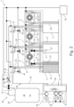
- FIG. 1 shows a system for storing and recovering energy with three liquid containers
- FIGS. 2 , 3 and 4 show the system according to FIG. 1 in a snapshot at the beginning of an energy supply cycle.
- FIG. 1 shows a system 1 for storing and recovering energy, hereinafter referred to as system 1 for short.
- the system 1 has a first, second and third liquid container 2 , 3 , and 4 , wherein each liquid container 2 - 4 has a capacity of, for example, approximately 1 million cubic metres of water and all liquid containers 2 - 4 stand on a flat bottom plate 5 so that they are at the same level.
- the liquid containers 2 - 4 are made of concrete/reinforced concrete and are built in such a way that they can withstand the pressures prevailing in the system 1 with sufficient safety, which also applies to all other components of the system 1 .
- the system 1 further comprises a first, second and third turbine unit 6 , 7 and 8 , the turbine units being equipped with Pelton turbines 9 for power generation, which are installed above the liquid containers 2 - 4 as shown in FIG. 1 .
- the Pelton turbines 9 are each connected to a generator (not shown) so that this unit comprising turbine and generator can convert kinetic energy into electrical energy.
- the first turbine unit 6 connects the first liquid container 2 to the second liquid container 3 in such a way that the liquid can flow from the first liquid container 2 through the Pelton turbine 9 into the second liquid container 3 , thereby driving the Pelton turbine 9 .
- the first turbine unit 6 has, on the inlet side, a first turbine inlet piping 10 with a first turbine inlet valve 11 and with a first riser 12 , which extends close to the bottom of the first liquid container 2 or its pump sump-like recess, where it allows liquid to exit from the first liquid container 2 .
- the first turbine unit 6 On the outlet side, the first turbine unit 6 has a first outlet piping 13 with a first outlet valve 14 , wherein the first outlet piping 13 is coupled at the top to the second liquid container 3 , where it allows liquid to enter the latter.
- the first liquid container which is indeed under e.g. 100 bar compressed air, must be returned to the pressure accumulator via the compressor station. This saves approx. 50% energy, as the compressor station is supplied with compressed air at an average of 50 bar, raised to the setpoint, e.g. 150 bar, and stored in the pressure accumulator for reuse).
- the second turbine unit 7 connects the second liquid container 3 to the third liquid container 4 in such a way that the liquid can flow from the second liquid container 3 through the Pelton turbine 9 into the third liquid container 4 , thereby driving the Pelton turbine 9 .
- the second turbine unit 7 has, on the inlet side, a second turbine inlet piping 15 with a second turbine inlet valve 16 and with a second riser 17 , which extends close to the bottom of the second liquid container 3 or its pump sump-like recess, where it allows liquid to exit from the second liquid container 3 .
- the second turbine unit 7 On the outlet side, has a second outlet piping 18 with a second outlet valve 19 , wherein the second outlet piping 18 is coupled at the top to the third liquid container 4 , where it allows liquid to enter the latter.
- the third turbine unit 8 connects the third liquid container 4 to the first liquid container 2 in such a way that the liquid can flow from the third liquid container 4 through the Pelton turbine 9 into the first liquid container 2 , thereby driving the Pelton turbine 9 .
- the third turbine unit 8 has, on the inlet side, a third turbine inlet piping 20 with a third turbine inlet valve 21 and with a third riser 22 , which extends close to the bottom of the third liquid container 4 or its pump sump-like recess, where it allows liquid to exit from the third liquid container 4 .
- the third turbine unit 8 On the outlet side, the third turbine unit 8 has a third outlet piping 23 with a first outlet valve 24 , wherein the third outlet piping 24 is coupled at the top to the first liquid container 2 , where it allows liquid to enter the latter.
- the system 1 further comprises a working gas supply unit 25 for providing a working gas 26 as air, having a substantially constant working gas pressure P 1 , the working gas supply unit 25 comprising a working gas supply system 27 which enables the working gas 26 with constant working gas pressure P 1 to be supplied to the liquid containers 2 - 4 .
- the working gas supply system 27 has a multi-stage (here, for example, a three-stage) compressor 28 which is used to compress air, which is supplied to it primarily as ambient air on the inlet side,
- the compressor 28 On the outlet side, the compressor 28 is connected to a pressure accumulator 29 , in which the working gas 26 is stored at the storage pressure P 2 .
- a non-return valve which is not shown in the figures, is advantageously provided between the compressor 28 and the pressure accumulator 29 .
- the working gas supply system 27 is connected to the pressure accumulator 29 , which has a shut-off valve 30 on the inlet side that is initially closed, e.g. when starting up the system 1 , until the storage pressure P 2 has built up. Furthermore, the working gas supply system 27 has a pressure regulator 31 , by means of which the storage pressure P 2 is lowered to the working gas pressure P 1 .
- the working gas supply system 27 has a central supply line 32 that couples to the pressure regulator 31 on the inlet side.
- a first supply line 33 branches off from the central supply line 32 and has a first supply valve 34 , the first supply line 33 flowing into the first liquid container 2 on the top side, so that the working gas 26 can be supplied there when the first supply valve 34 is open.
- a second supply line 35 branches off from the central supply line 32 and has a second supply valve 36 , the second supply line 35 flowing into the second liquid container 3 on the top side, so that the working gas 26 can be supplied there when the second supply valve 36 is open.
- a third supply line 37 branches off from the central supply line 32 and has a third supply valve 38 , the third supply line 37 flowing into the third liquid container 4 on the top side, so that the working gas 26 can be supplied there when the third supply valve 38 is open.
- the working gas supply unit 25 further comprises a working gas recirculation system 39 which allows the working gas 26 located in the liquid containers 2 - 4 and under pressure to be returned to the compressor 28 and to be used there, that is, to use the pressure of the working gas 26 so that it is not necessary to compress the ambient air away from the pressure of the ambient air each time the pressure accumulator 29 is refilled.
- a working gas recirculation system 39 which allows the working gas 26 located in the liquid containers 2 - 4 and under pressure to be returned to the compressor 28 and to be used there, that is, to use the pressure of the working gas 26 so that it is not necessary to compress the ambient air away from the pressure of the ambient air each time the pressure accumulator 29 is refilled.
- the working gas recirculation system 39 has a central recirculation line 40 that flows into the compressor 28 on the outlet side.
- a first recirculation line 41 branches off from the central recirculation line 40 and has a first recirculation valve 42 , the first recirculation line 41 flowing into the first liquid container 2 on the top side, so that the working gas 26 can be returned from there to the compressor 28 when the first recirculation valve 42 is open.
- the first recirculation line 41 is coupled to a first vent valve 43 open to the environment, which allows venting of the first liquid container 2 to the environment when the first vent valve 43 is open.
- a second recirculation line 44 branches off from the central recirculation line 40 and has a second recirculation valve 45 , the second recirculation line 44 flowing into the second liquid container 3 on the top side, so that the working gas 26 can be returned from there to the compressor 28 when the second recirculation valve 45 is open.
- the second recirculation line 44 is coupled to a second vent valve 46 open to the environment, which allows venting of the second liquid container 3 to the environment when the second vent valve 46 is open.
- a third recirculation line 47 branches off from the central recirculation line 40 and has a third recirculation valve 48 , the third recirculation line 47 flowing into the third liquid container 4 on the top side, so that the working gas 26 can be returned from there to the compressor 28 when the third recirculation valve 48 is open.
- the third recirculation line 48 is coupled to a third vent valve 49 open to the environment, which allows venting of the third liquid container 4 to the environment when the third vent valve 49 is open.
- the compressor 28 has a supply air selection unit 50 on the inlet side, to which on the one hand the pre-compressed working gas 26 can be supplied by means of the central recirculation line 40 and to which on the other hand the ambient air can also be supplied.
- the supply air selection unit 50 may be used to select whether the pre-compressed working gas 26 is to be used for compression or whether the ambient air is to be compressed. In particular, when using the pre-compressed working gas 26 , the supply air selection unit 50 may be used to determine which stage(s) of the compressor 28 should be used for optimised compression.
- liquid containers 2 - 4 With regard to the liquid containers 2 - 4 , it should be noted that these are hermetically sealed, of course with the exception of the connections to the pipes carrying working gas 26 or liquid.
- the system 1 has a control unit 52 which is designed to control or regulate all the valves 30 , 34 , 36 , 38 , 42 , 45 , 48 , 43 , 46 , 49 , 11 , 14 , 16 , 19 , 21 , 24 , or their actuators, which open or close the corresponding valves, the supply air selection unit 50 or its actuators, as well as the pressure regulator 31 or its actuator, and the motors 53 of the compressor 28 .
- the control unit 52 may be, for example, a central server with appropriate programming, which sends its control signals to the various electronically controllable system components (such as the aforementioned valves, etc.).
- sub-control units may also be provided, which are positioned, e.g., in a decentralised manner on the respective system components to be controlled, and which are controlled in a coordinating manner by a superordinate control unit.
- the compressor 28 or its motors 53 may be controlled to compress ambient air or working gas 26 from one of the liquid containers 2 , 3 , 4 to the storage pressure P 2 and to feed it into the pressure accumulator 29 .
- This means that the excess energy of the power grid is used to fill the pressure accumulator 29 with working gas 26 or air.
- further steps such as filtration and dehumidification of the air can be carried out upstream.
- the phases between energy surplus and energy demand are fluctuating and can have different time intervals.
- the energy demand is usually higher during the day than at night.
- longer periods of time are also possible.
- wind parks may have a seasonal energy surplus over a longer period of time, followed by weeks or months in which the energy demand cannot be met by the wind parks alone (without energy storage).
- the working gas 26 may also be stored for long periods of time.
- FIGS. 2 to 4 show schematic diagrams of the energy recovery process, with each FIG. 2 , 3 , 4 representing an energy supply cycle.
- the first liquid container 2 is substantially completely filled with liquid 51 , in this case water.
- the other two liquid containers 3 and 4 are substantially completely empty.
- the pressure accumulator 29 is filled with working gas 26 , in this case air, which has a storage pressure P 2 that is higher than the working pressure P 1 .
- the shut-off valve 30 , the first supply valve 34 , the first turbine inlet valve 11 , the first outlet valve 14 and the second vent valve 46 are open. The remaining valves are closed.
- the pressure regulator 31 keeps the working pressure P 1 of the working gas 26 constant.
- the working gas 26 pushes on the liquid 51 in the first liquid container 2 with the working pressure P 1 .
- the liquid 51 is pushed through the first turbine inlet piping 10 , through the first turbine inlet valve 11 , through the Pelton turbine 9 , through the first outlet piping 13 , through the first outlet valve 14 , i.e. through the first turbine unit 6 , into the second liquid container 3 .
- the generator feeds the recovered energy into the power grid (not shown). Because the second vent valve 46 is open, the liquid 51 flowing into the second liquid container 3 can displace the air out of the second liquid container 3 through the second vent valve 46 . Thus, there is a substantially constant pressure in the second liquid container 3 . Because the pressure in the first liquid container 2 also corresponds to the constant working pressure P 1 , a constant pressure difference is established between the two liquid containers 2 and 3 . This causes the Pelton turbine 9 to operate at a constant speed (except for the run-in and run-out phases).
- shut-off valve 30 the second supply valve 36 , the second turbine inlet valve 16 , the second outlet valve 19 and the third vent valve 49 are open.
- the remaining valves are closed. This means that the previously opened first supply valve 34 , the first turbine inlet valve 11 , the first outlet valve 14 and the second vent valve 46 are now closed.
- the pressure regulator 31 keeps the working pressure P 1 of the working gas 26 constant.
- the working gas 26 pushes on the liquid in the second liquid container 3 with the working pressure P 1 .
- the liquid is pushed through the second turbine inlet piping 15 , through the second turbine inlet valve 16 , through the Pelton turbine 9 , through the second outlet piping 18 , through the second outlet valve 19 , i.e. through the second turbine unit 7 , into the third liquid container 4 .
- the generator feeds the recovered energy into the power grid.
- the first liquid container 2 still contains the working gas 26 at a pressure that corresponds approximately to the working pressure P 1 .
- the control unit 52 can now decide, based on internal and external information, whether it makes more sense to run a high pressure or a low pressure mode, as described below. What is considered more appropriate may vary depending on the preference of the operator. For example, regulation may depend on economic or ecological aspects. Also, the load on the individual system components may be taken into account, and a durability of these may be considered as a reasonable regulation. Optimal target values or a compromise of these target values may also be considered appropriate and aimed for in the regulation.
- the storage pressure P 2 is always higher than or at least equal to the working pressure P 1 .
- the storage pressure P 2 may be slightly higher than the working pressure P 1 in order to be able to recirculate the working gas with as little energy demand as possible.
- This low-pressure mode makes it possible to run through several energy supply cycles as efficiently as possible.
- the working pressure P 1 may be 100 bar and the storage pressure P 2 may be 120 (to 150) bar.
- This may also be useful, for example, if large but less pressure-resistant pressure accumulators 29 , such as natural underground accumulators, are used. In most cases, however, it is desirable to store as much energy as possible in as little space as possible.
- the pressure accumulator 29 may also be designed as a high-pressure accumulator for storage pressures P 2 of, for example, 1000 bar.
- the storage pressure P 2 is relatively high, for example 1000 bar
- the working pressure P 1 is much lower in comparison, for example 100 bar
- the system 1 may be operated in a high-pressure mode such that the working gas 26 , which at the end of the energy supply cycle is in that pressure vessel 2 which is to be refilled with liquid 51 , is not returned to the working gas supply unit 25 but is vented through the vent valve 43 .
- the advantages of these two systems or modes may also be combined. In this way, in case of an energy surplus, the working gas may be stored up to high storage pressures of, for example, 1000 bar.
- the system may then be operated as described for low pressure differences, in low pressure mode. Therefore, as long as the storage pressure P 2 is substantially higher than the working pressure P 1 , the valves are switched in such a way that the working gas 26 is released into the environment through the respective vent valves 43 , 46 , 49 at the end of the energy supply cycle. So, for example, the working gas 26 leaks out of the liquid container 2 after the liquid has been conveyed from it into the liquid container 3 , through the vent valve 43 .
- the valves are switched so that the working gas 26 is conveyed through the respective recirculation lines 41 , 44 , 47 and the respective recirculation valves 42 , 45 , 48 . So, for example, the working gas 26 from the liquid container 2 , after the liquid 51 has been conveyed from it to the liquid container 3 , is conveyed back to the working gas supply unit 25 through the recirculation line 41 and through the recirculation valve 42 .
- control unit 52 This regulation is performed by the control unit 52 .
- the system is equipped with the necessary actuators to control the various valves, the motors 53 of the compressors 28 , and the pressure regulator 31 , as well as the corresponding usual sensors (which have not been shown in order not to further overload the figures).
- the control unit 52 is designed to use the various information from the sensors, as well as external factors such as energy demand or energy surplus, to decide which mode is the most appropriate and to control the actuators accordingly.
- the working gas 26 leaks from the first liquid container 2 through the first vent valve 43 .
- the working gas 26 is fed through the first recirculation line 41 and through the first recirculation valve 42 , through the central recirculation line 40 into the supply air selection unit 50 .
- the working gas 26 is compressed to the storage pressure P 2 by the compressor stage(s) of the compressor 28 that are optimal for the respective pressure, and fed into the pressure accumulator 29 .
- the shut-off valve 30 , the third supply valve 38 , the third turbine inlet valve 21 , the third outlet valve 24 and the first vent valve 43 are open. The remaining valves are closed. This means that the previously opened second supply valve 36 , the second turbine inlet valve 16 , the second outlet valve 19 and the third vent valve 49 are now closed.
- the pressure regulator 31 keeps the working pressure P 1 of the working gas 26 constant.
- the working gas 26 pushes on the liquid 51 in the third liquid container 4 with the working pressure P 1 .
- the liquid 51 is pushed through the third turbine inlet piping 20 , through the third turbine inlet valve 21 , through the Pelton turbine 9 , through the third outlet piping 23 , through the third outlet valve 24 , i.e.
- the Pelton turbine 9 is operated at a constant speed (except for the run-in and run-out phases).
- the control unit 52 now starts a high-pressure mode or a low-pressure mode for the second liquid container 3 filled with working gas 26 .
- the working gas 26 is vented from the second liquid container 3 through the second vent valve 46 .
- the working gas 26 is fed through the second recirculation line 44 and through the second recirculation valve 45 , through the central recirculation line 40 into the supply air selection unit 50 .
- the working gas 26 is compressed to the storage pressure P 2 by the compressor stage(s) of the compressor 28 that are optimal for the respective pressure, and fed into the pressure accumulator 29 .
- the energy supply cycle can start again as shown in FIG. 2 .
- the energy recovery over the series of energy supply cycles can therefore run seamlessly, and in such a way that the intermediate filling of additional containers without energy recovery can be omitted.
- Heat is generated when the working gas 26 is compressed in the compressor 28 .
- the heat may be stored in heat accumulators. It may then be used at a later time, when there is a demand for energy and the working gas 26 is expanded by the pressure regulator 31 and thereby cooled, to heat the expanding working gas 26 .
- a heat exchanger may be provided which is designed to remove the heat generated during compression from the compressor 28 and use it to evaporate water that drives a steam turbine. This kinetic energy may be used in various ways to increase the efficiency of the system 1 .
- the control unit 52 has its own emergency energy storage to supply itself and the actuators with energy in the event of a power failure. Furthermore, the valves may also be operated manually or with an appropriate tool. System 1 is therefore black start capable. In the event of a power failure, the system 1 can also start the energy recovery cycle without external intervention. For this purpose, the valves are switched in the same way as during normal start-up. The emergency energy storage is used to switch the valves. If it does not contain sufficient energy, the valves may also be switched manually accordingly. As soon as the first energy supply cycle has started, sufficient electrical energy is provided for the operation of the system 1 , in order to switch autonomously to the other energy supply cycles.
- liquid containers 2 , 3 , 4 do not necessarily have to be arranged as shown in the figures. They may also be placed side by side to save space, or arranged in a way that is advantageous according to the landscape conditions. They may also have different shapes. They may be rectangular or cubic, but also spherical or cylindrical. It is also possible, for example, for a cylindrical container, for example, to be divided into several segments, for example into three segments, each segment acting as a liquid container as described here. This makes it possible to achieve an extremely short pipe routing and accordingly optimise or reduce the pipe resistance.
- the number of energy recovery cycles that the system 1 can provide without recharging the pressure accumulator 29 ultimately depends on the amount of gas stored in the pressure accumulator 29 at the storage pressure P 2 .
Landscapes
- Engineering & Computer Science (AREA)
- Chemical & Material Sciences (AREA)
- Combustion & Propulsion (AREA)
- Mechanical Engineering (AREA)
- General Engineering & Computer Science (AREA)
- Power Engineering (AREA)
- Other Liquid Machine Or Engine Such As Wave Power Use (AREA)
- Filling Or Discharging Of Gas Storage Vessels (AREA)
- Life Sciences & Earth Sciences (AREA)
- Sustainable Development (AREA)
- Sustainable Energy (AREA)
Abstract
Description
-
- to a storage pressure P2 which is higher than the working pressure P1. For this purpose, the
compressor 28 hasseveral motors 53 that may be operated with electrical energy from the power grid.
- to a storage pressure P2 which is higher than the working pressure P1. For this purpose, the
Claims (6)
Applications Claiming Priority (3)
| Application Number | Priority Date | Filing Date | Title |
|---|---|---|---|
| DE102020112724.3 | 2020-05-11 | ||
| DE102020112724.3A DE102020112724A1 (en) | 2020-05-11 | 2020-05-11 | Energy storage and recovery system |
| PCT/EP2021/061295 WO2021228569A1 (en) | 2020-05-11 | 2021-04-29 | System for storing and recovering energy |
Publications (2)
| Publication Number | Publication Date |
|---|---|
| US20230175472A1 US20230175472A1 (en) | 2023-06-08 |
| US12331711B2 true US12331711B2 (en) | 2025-06-17 |
Family
ID=75801577
Family Applications (1)
| Application Number | Title | Priority Date | Filing Date |
|---|---|---|---|
| US17/924,391 Active 2041-06-11 US12331711B2 (en) | 2020-05-11 | 2021-04-29 | System for storing and recovering energy |
Country Status (4)
| Country | Link |
|---|---|
| US (1) | US12331711B2 (en) |
| EP (1) | EP4150203A1 (en) |
| DE (1) | DE102020112724A1 (en) |
| WO (1) | WO2021228569A1 (en) |
Families Citing this family (2)
| Publication number | Priority date | Publication date | Assignee | Title |
|---|---|---|---|---|
| WO2022097113A1 (en) * | 2020-11-09 | 2022-05-12 | Bennamann Services, Ltd. | Systems and methods for smoothing and storage of intermittent renewable power |
| CN115875244B (en) * | 2023-02-13 | 2023-05-16 | 西安热工研究院有限公司 | Constant-pressure full-capacity energy release type compressed air energy storage system and energy storage method |
Citations (9)
| Publication number | Priority date | Publication date | Assignee | Title |
|---|---|---|---|---|
| WO1993006367A1 (en) | 1991-09-25 | 1993-04-01 | Grupping Arnold | A system for subterranean storage of energy |
| US20020144504A1 (en) * | 2001-04-10 | 2002-10-10 | New World Generation Inc., A Corporation | Wind powered hydroelectric power plant and method of operation thereof |
| US7579700B1 (en) | 2008-05-28 | 2009-08-25 | Moshe Meller | System and method for converting electrical energy into pressurized air and converting pressurized air into electricity |
| WO2013141826A2 (en) * | 2012-03-21 | 2013-09-26 | Cakmakci Huseyin Avni | Method for electric generation by using fluid channelling via sequential siphoning technique and device using the same |
| US20170264164A1 (en) * | 2014-09-29 | 2017-09-14 | Siemens Aktiengesellschaft | Device and Method for Storing Energy |
| WO2018069925A1 (en) * | 2016-10-10 | 2018-04-19 | Mesinger Jeshoa | A hydraulic-pneumatic energy storage and recovery system |
| US20180156184A1 (en) * | 2016-12-07 | 2018-06-07 | Olalekan A. Alao | Energy storage and generation system |
| WO2019061002A1 (en) | 2017-09-27 | 2019-04-04 | Universidad Técnica Federico Santa María | System and method for energy storage and generation, wherein pressure is released in a liquid cercuit which in turn drives a liquid turbine for energy generation |
| DE102018111997A1 (en) | 2018-05-18 | 2019-11-21 | Stefan Lenzer | Storage generator for energy |
Family Cites Families (3)
| Publication number | Priority date | Publication date | Assignee | Title |
|---|---|---|---|---|
| DE102013112196A1 (en) | 2013-02-18 | 2014-01-23 | Ed. Züblin Ag | Method for recovering mechanical energy from compressed gas in compressed gas reservoir, involves controlling quasi-isothermal expansion of compressed gas, to produce electrical energy from mechanical work of working machine |
| DK3321501T3 (en) | 2015-12-22 | 2019-10-21 | Renestor M Gmbh | ENERGY STORAGE AND RECOVERY SYSTEM |
| DE102016002749A1 (en) | 2016-03-08 | 2017-12-07 | Volker Mothes | Energy storage, combined by air pressure and water |
-
2020
- 2020-05-11 DE DE102020112724.3A patent/DE102020112724A1/en not_active Withdrawn
-
2021
- 2021-04-29 EP EP21723686.8A patent/EP4150203A1/en active Pending
- 2021-04-29 US US17/924,391 patent/US12331711B2/en active Active
- 2021-04-29 WO PCT/EP2021/061295 patent/WO2021228569A1/en not_active Ceased
Patent Citations (11)
| Publication number | Priority date | Publication date | Assignee | Title |
|---|---|---|---|---|
| WO1993006367A1 (en) | 1991-09-25 | 1993-04-01 | Grupping Arnold | A system for subterranean storage of energy |
| US20020144504A1 (en) * | 2001-04-10 | 2002-10-10 | New World Generation Inc., A Corporation | Wind powered hydroelectric power plant and method of operation thereof |
| US7579700B1 (en) | 2008-05-28 | 2009-08-25 | Moshe Meller | System and method for converting electrical energy into pressurized air and converting pressurized air into electricity |
| WO2013141826A2 (en) * | 2012-03-21 | 2013-09-26 | Cakmakci Huseyin Avni | Method for electric generation by using fluid channelling via sequential siphoning technique and device using the same |
| US20170264164A1 (en) * | 2014-09-29 | 2017-09-14 | Siemens Aktiengesellschaft | Device and Method for Storing Energy |
| WO2018069925A1 (en) * | 2016-10-10 | 2018-04-19 | Mesinger Jeshoa | A hydraulic-pneumatic energy storage and recovery system |
| US20190242357A1 (en) * | 2016-10-10 | 2019-08-08 | Jeshoa MESINGER | A hydraulic-pneumatic energy storage and recovery system |
| US20180156184A1 (en) * | 2016-12-07 | 2018-06-07 | Olalekan A. Alao | Energy storage and generation system |
| WO2019061002A1 (en) | 2017-09-27 | 2019-04-04 | Universidad Técnica Federico Santa María | System and method for energy storage and generation, wherein pressure is released in a liquid cercuit which in turn drives a liquid turbine for energy generation |
| US20200277896A1 (en) * | 2017-09-27 | 2020-09-03 | Universidad Técnica Federico Santa María | System and method to store and generate energy where a pressure is released into a liquid circuit which in turn moves a liquid turbine to generate power |
| DE102018111997A1 (en) | 2018-05-18 | 2019-11-21 | Stefan Lenzer | Storage generator for energy |
Non-Patent Citations (1)
| Title |
|---|
| International Search Report and the Written Opinion Dated Jun. 8, 2021 From the International Searching Authority Re. Application No. PCT/EP2021/061295 and its Translation into English. (11 Pages). |
Also Published As
| Publication number | Publication date |
|---|---|
| DE102020112724A1 (en) | 2021-11-11 |
| US20230175472A1 (en) | 2023-06-08 |
| EP4150203A1 (en) | 2023-03-22 |
| WO2021228569A1 (en) | 2021-11-18 |
Similar Documents
| Publication | Publication Date | Title |
|---|---|---|
| DK3049667T3 (en) | Process and system for combined pump water pressure-compressed air-energy storage with constant turbine-water pressure | |
| EP2516827B1 (en) | Compressed air energy storage system | |
| US12218499B2 (en) | Hydraulic compressed air energy storage system | |
| EP2971928A1 (en) | Active volume energy level large scale sub-sea energy fluids storage methods and apparatus for power generation and integration of renewable energy sources | |
| US12331711B2 (en) | System for storing and recovering energy | |
| DK3184807T3 (en) | ENERGY STORAGE AND RECOVERY SYSTEM | |
| US9267492B2 (en) | Power transfer and generation using pressurized fluids | |
| CN114458517B (en) | Energy storage system and control method thereof | |
| US12322966B2 (en) | System and method for storing energy, and for recovering stored energy by using liquid and gas as pistons | |
| EP3693568B1 (en) | System and method for energy storage and generation, wherein pressure is released in a liquid circuit which in turn drives a liquid turbine for energy generation | |
| US20180355838A1 (en) | Generating energy by means of autarchic type 2.1 to type 4.1 hydroelectric power plants | |
| RU2614451C1 (en) | Independent power source based on wind power installation | |
| US9353756B2 (en) | Method for the controlling and feeding of a power plant and power plant | |
| RU2823114C1 (en) | Air-gravity accumulator of electric energy | |
| EP4376249A1 (en) | Hydrogen production apparatus, electrical energy supply arrangement and method for operating a hydrogen production apparatus | |
| JP2012057528A (en) | Hydraulic power generation system |
Legal Events
| Date | Code | Title | Description |
|---|---|---|---|
| FEPP | Fee payment procedure |
Free format text: ENTITY STATUS SET TO UNDISCOUNTED (ORIGINAL EVENT CODE: BIG.); ENTITY STATUS OF PATENT OWNER: SMALL ENTITY |
|
| FEPP | Fee payment procedure |
Free format text: ENTITY STATUS SET TO SMALL (ORIGINAL EVENT CODE: SMAL); ENTITY STATUS OF PATENT OWNER: SMALL ENTITY |
|
| STPP | Information on status: patent application and granting procedure in general |
Free format text: DOCKETED NEW CASE - READY FOR EXAMINATION |
|
| STPP | Information on status: patent application and granting procedure in general |
Free format text: NON FINAL ACTION MAILED |
|
| STPP | Information on status: patent application and granting procedure in general |
Free format text: RESPONSE TO NON-FINAL OFFICE ACTION ENTERED AND FORWARDED TO EXAMINER |
|
| STPP | Information on status: patent application and granting procedure in general |
Free format text: FINAL REJECTION MAILED |
|
| STPP | Information on status: patent application and granting procedure in general |
Free format text: RESPONSE AFTER FINAL ACTION FORWARDED TO EXAMINER |
|
| STPP | Information on status: patent application and granting procedure in general |
Free format text: ADVISORY ACTION MAILED |
|
| STPP | Information on status: patent application and granting procedure in general |
Free format text: DOCKETED NEW CASE - READY FOR EXAMINATION |
|
| STPP | Information on status: patent application and granting procedure in general |
Free format text: NON FINAL ACTION MAILED |
|
| STPP | Information on status: patent application and granting procedure in general |
Free format text: RESPONSE TO NON-FINAL OFFICE ACTION ENTERED AND FORWARDED TO EXAMINER |
|
| STPP | Information on status: patent application and granting procedure in general |
Free format text: NOTICE OF ALLOWANCE MAILED -- APPLICATION RECEIVED IN OFFICE OF PUBLICATIONS |
|
| STCF | Information on status: patent grant |
Free format text: PATENTED CASE |