US12121394B2 - Coherent spread-spectrum coded waveforms in synthetic aperture image formation - Google Patents
Coherent spread-spectrum coded waveforms in synthetic aperture image formation Download PDFInfo
- Publication number
- US12121394B2 US12121394B2 US18/177,649 US202318177649A US12121394B2 US 12121394 B2 US12121394 B2 US 12121394B2 US 202318177649 A US202318177649 A US 202318177649A US 12121394 B2 US12121394 B2 US 12121394B2
- Authority
- US
- United States
- Prior art keywords
- waveforms
- acoustic
- waveform
- composite
- array
- Prior art date
- Legal status (The legal status is an assumption and is not a legal conclusion. Google has not performed a legal analysis and makes no representation as to the accuracy of the status listed.)
- Active
Links
Images


Classifications
-
- A—HUMAN NECESSITIES
- A61—MEDICAL OR VETERINARY SCIENCE; HYGIENE
- A61B—DIAGNOSIS; SURGERY; IDENTIFICATION
- A61B8/00—Diagnosis using ultrasonic, sonic or infrasonic waves
- A61B8/13—Tomography
- A61B8/14—Echo-tomography
-
- A—HUMAN NECESSITIES
- A61—MEDICAL OR VETERINARY SCIENCE; HYGIENE
- A61B—DIAGNOSIS; SURGERY; IDENTIFICATION
- A61B8/00—Diagnosis using ultrasonic, sonic or infrasonic waves
- A61B8/44—Constructional features of the ultrasonic, sonic or infrasonic diagnostic device
- A61B8/4444—Constructional features of the ultrasonic, sonic or infrasonic diagnostic device related to the probe
- A61B8/4461—Features of the scanning mechanism, e.g. for moving the transducer within the housing of the probe
-
- A—HUMAN NECESSITIES
- A61—MEDICAL OR VETERINARY SCIENCE; HYGIENE
- A61B—DIAGNOSIS; SURGERY; IDENTIFICATION
- A61B8/00—Diagnosis using ultrasonic, sonic or infrasonic waves
- A61B8/44—Constructional features of the ultrasonic, sonic or infrasonic diagnostic device
- A61B8/4483—Constructional features of the ultrasonic, sonic or infrasonic diagnostic device characterised by features of the ultrasound transducer
- A61B8/4494—Constructional features of the ultrasonic, sonic or infrasonic diagnostic device characterised by features of the ultrasound transducer characterised by the arrangement of the transducer elements
-
- G—PHYSICS
- G01—MEASURING; TESTING
- G01S—RADIO DIRECTION-FINDING; RADIO NAVIGATION; DETERMINING DISTANCE OR VELOCITY BY USE OF RADIO WAVES; LOCATING OR PRESENCE-DETECTING BY USE OF THE REFLECTION OR RERADIATION OF RADIO WAVES; ANALOGOUS ARRANGEMENTS USING OTHER WAVES
- G01S15/00—Systems using the reflection or reradiation of acoustic waves, e.g. sonar systems
- G01S15/88—Sonar systems specially adapted for specific applications
- G01S15/89—Sonar systems specially adapted for specific applications for mapping or imaging
- G01S15/8906—Short-range imaging systems; Acoustic microscope systems using pulse-echo techniques
- G01S15/8909—Short-range imaging systems; Acoustic microscope systems using pulse-echo techniques using a static transducer configuration
- G01S15/8913—Short-range imaging systems; Acoustic microscope systems using pulse-echo techniques using a static transducer configuration using separate transducers for transmission and reception
-
- G—PHYSICS
- G01—MEASURING; TESTING
- G01S—RADIO DIRECTION-FINDING; RADIO NAVIGATION; DETERMINING DISTANCE OR VELOCITY BY USE OF RADIO WAVES; LOCATING OR PRESENCE-DETECTING BY USE OF THE REFLECTION OR RERADIATION OF RADIO WAVES; ANALOGOUS ARRANGEMENTS USING OTHER WAVES
- G01S15/00—Systems using the reflection or reradiation of acoustic waves, e.g. sonar systems
- G01S15/88—Sonar systems specially adapted for specific applications
- G01S15/89—Sonar systems specially adapted for specific applications for mapping or imaging
- G01S15/8906—Short-range imaging systems; Acoustic microscope systems using pulse-echo techniques
- G01S15/8909—Short-range imaging systems; Acoustic microscope systems using pulse-echo techniques using a static transducer configuration
- G01S15/8915—Short-range imaging systems; Acoustic microscope systems using pulse-echo techniques using a static transducer configuration using a transducer array
- G01S15/8927—Short-range imaging systems; Acoustic microscope systems using pulse-echo techniques using a static transducer configuration using a transducer array using simultaneously or sequentially two or more subarrays or subapertures
-
- G—PHYSICS
- G01—MEASURING; TESTING
- G01S—RADIO DIRECTION-FINDING; RADIO NAVIGATION; DETERMINING DISTANCE OR VELOCITY BY USE OF RADIO WAVES; LOCATING OR PRESENCE-DETECTING BY USE OF THE REFLECTION OR RERADIATION OF RADIO WAVES; ANALOGOUS ARRANGEMENTS USING OTHER WAVES
- G01S15/00—Systems using the reflection or reradiation of acoustic waves, e.g. sonar systems
- G01S15/88—Sonar systems specially adapted for specific applications
- G01S15/89—Sonar systems specially adapted for specific applications for mapping or imaging
- G01S15/8906—Short-range imaging systems; Acoustic microscope systems using pulse-echo techniques
- G01S15/8959—Short-range imaging systems; Acoustic microscope systems using pulse-echo techniques using coded signals for correlation purposes
-
- G—PHYSICS
- G01—MEASURING; TESTING
- G01S—RADIO DIRECTION-FINDING; RADIO NAVIGATION; DETERMINING DISTANCE OR VELOCITY BY USE OF RADIO WAVES; LOCATING OR PRESENCE-DETECTING BY USE OF THE REFLECTION OR RERADIATION OF RADIO WAVES; ANALOGOUS ARRANGEMENTS USING OTHER WAVES
- G01S15/00—Systems using the reflection or reradiation of acoustic waves, e.g. sonar systems
- G01S15/88—Sonar systems specially adapted for specific applications
- G01S15/89—Sonar systems specially adapted for specific applications for mapping or imaging
- G01S15/8906—Short-range imaging systems; Acoustic microscope systems using pulse-echo techniques
- G01S15/8997—Short-range imaging systems; Acoustic microscope systems using pulse-echo techniques using synthetic aperture techniques
-
- A—HUMAN NECESSITIES
- A61—MEDICAL OR VETERINARY SCIENCE; HYGIENE
- A61B—DIAGNOSIS; SURGERY; IDENTIFICATION
- A61B8/00—Diagnosis using ultrasonic, sonic or infrasonic waves
- A61B8/44—Constructional features of the ultrasonic, sonic or infrasonic diagnostic device
- A61B8/4483—Constructional features of the ultrasonic, sonic or infrasonic diagnostic device characterised by features of the ultrasound transducer
- A61B8/4488—Constructional features of the ultrasonic, sonic or infrasonic diagnostic device characterised by features of the ultrasound transducer the transducer being a phased array
-
- A—HUMAN NECESSITIES
- A61—MEDICAL OR VETERINARY SCIENCE; HYGIENE
- A61B—DIAGNOSIS; SURGERY; IDENTIFICATION
- A61B8/00—Diagnosis using ultrasonic, sonic or infrasonic waves
- A61B8/46—Ultrasonic, sonic or infrasonic diagnostic devices with special arrangements for interfacing with the operator or the patient
- A61B8/461—Displaying means of special interest
- A61B8/463—Displaying means of special interest characterised by displaying multiple images or images and diagnostic data on one display
-
- A—HUMAN NECESSITIES
- A61—MEDICAL OR VETERINARY SCIENCE; HYGIENE
- A61B—DIAGNOSIS; SURGERY; IDENTIFICATION
- A61B8/00—Diagnosis using ultrasonic, sonic or infrasonic waves
- A61B8/52—Devices using data or image processing specially adapted for diagnosis using ultrasonic, sonic or infrasonic waves
- A61B8/5215—Devices using data or image processing specially adapted for diagnosis using ultrasonic, sonic or infrasonic waves involving processing of medical diagnostic data
- A61B8/5223—Devices using data or image processing specially adapted for diagnosis using ultrasonic, sonic or infrasonic waves involving processing of medical diagnostic data for extracting a diagnostic or physiological parameter from medical diagnostic data
-
- A—HUMAN NECESSITIES
- A61—MEDICAL OR VETERINARY SCIENCE; HYGIENE
- A61B—DIAGNOSIS; SURGERY; IDENTIFICATION
- A61B8/00—Diagnosis using ultrasonic, sonic or infrasonic waves
- A61B8/54—Control of the diagnostic device
-
- G—PHYSICS
- G01—MEASURING; TESTING
- G01S—RADIO DIRECTION-FINDING; RADIO NAVIGATION; DETERMINING DISTANCE OR VELOCITY BY USE OF RADIO WAVES; LOCATING OR PRESENCE-DETECTING BY USE OF THE REFLECTION OR RERADIATION OF RADIO WAVES; ANALOGOUS ARRANGEMENTS USING OTHER WAVES
- G01S15/00—Systems using the reflection or reradiation of acoustic waves, e.g. sonar systems
- G01S15/88—Sonar systems specially adapted for specific applications
- G01S15/89—Sonar systems specially adapted for specific applications for mapping or imaging
- G01S15/8906—Short-range imaging systems; Acoustic microscope systems using pulse-echo techniques
- G01S15/8934—Short-range imaging systems; Acoustic microscope systems using pulse-echo techniques using a dynamic transducer configuration
- G01S15/8945—Short-range imaging systems; Acoustic microscope systems using pulse-echo techniques using a dynamic transducer configuration using transducers mounted for linear mechanical movement
Definitions
- This patent document relates to acoustic image formation.
- Acoustic imaging is an imaging modality that employs the properties of sound waves traveling through a medium to render a visual image.
- High frequency acoustic imaging has been used as an imaging modality for decades in a variety of biomedical fields to view internal structures and functions of animals and humans.
- High frequency acoustic waves used in biomedical imaging may operate in different frequencies, e.g., between 1 and 20 MHz, or even higher frequencies, and are often termed ultrasound waves.
- Techniques, systems, and devices are disclosed for synthetic aperture ultrasound imaging using coherent, spread-spectrum, instantaneous wideband, frequency- and/or phase-coded acoustic waveforms.
- the disclosed techniques, systems, and devices can be used to form one-dimensional (1D), two-dimensional (2D), and/or three-dimensional (3D) ultrasound images of biological tissue.
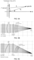
- FIG. 1 B shows a diagram of an ultrasound beam generated by a transducer array whose phase center is in successive positions to form a synthetic aperture beam in ultrasound imaging.
- FIG. 4 shows ambiguity function characteristics of an exemplary spread-spectrum coded waveform.
- FIG. 7 shows a diagram of exemplary synthetic aperture-sampled received echo data and storage to memory.
- FIG. 9 shows a diagram illustrating an exemplary implementation of the Stolt Transform process.
- FIG. 10 shows a block diagram of an exemplary iterative, closed-loop, synthetic aperture image autofocus subroutine.
- Ultrasound imaging can be performed by emitting an acoustic waveform (pulse) within a physical elastic medium, which is partly reflected from a boundary between two mediums (e.g., biological tissue structures) and partially transmitted.
- the reflection depends on the acoustic impedance difference between the two mediums (e.g., at the interface between two different biological tissue types).
- some of the acoustic energy of the transmitted acoustic waveform can be scattered back to the transducer at the interface to be received, and processed to extract information, while the remainder may travel on and to the next medium.
- scattering of the reflection may occur as the result of two or more impedances contained in the reflective medium acting as a scattering center.
- the acoustic energy can be refracted, diffracted, delayed, and/or attenuated based on the properties of the medium and/or the nature of the acoustic wave.
- a typical transducer may employ an array of piezoelectric elements to transmit an ultrasound pulse toward a target region (e.g., of a body of an organism) and receive the returned ultrasound signals (echoes) that return from scattering structures within.
- This transducer array functions as the aperture of the imaging system.
- Ultrasound pulses can be electronically steered and focused as a sequence pulses through a plane or volume and used to produce a 1D, 2D and/or 3D map of the returned echoes used to form an image of the target. Processes of steering and focusing ultrasound pulses is referred to as beamforming.
- the ultrasound pulse and the returned echoes transmitted and received at the transducer array can be individually delayed in time at each transducer of the array to act as a phased array.
- the image is typically acquired sequentially, one axial image line at a time (i.e., scan of the target area range slice by slice), which sets limits on the frame rate during imaging that may be detrimental in a variety of real-time ultrasound imaging applications, e.g., including the imaging of moving targets.
- synthetic aperture ultrasound imaging can be used to improve the quality of ultrasound images.
- a “synthetic aperture” is the concept in which the successive use of one or more smaller, real apertures (sub-apertures) to examine a VOI, whose phase centers are moved along a known one-dimensional (1D), two-dimensional (2D), and/or three-dimensional (3D) path of a particular or arbitrary shape, to realize a larger effective (non-real) aperture for acquiring an image.
- the synthetic aperture can be formed by mechanically altering the spatial position of the electro-acoustic transducer (e.g., transducer array) to the successive beam transmission and/or receiving locations, by electronically altering the phase center of the successive beam transmission and/or receiving locations on the electro-acoustic transducer array, or by a combination of both.
- Synthetic aperture-based imaging was originally used in radar systems to image large areas on the ground from aircraft scanning the area of interest from above. Synthetic aperture focusing in ultrasound imaging is based on the geometric distance from the ultrasound transmitting elements to the VOI location and the distance from that location back to the ultrasound receiving element.
- the use of the synthetic aperture enables the focusing on a point in the target region by analyzing the received amplitude and phase data of the returned echoes (e.g., mono-static and bi-static echoes), recorded at each of a plurality of transmitter and receiver positions from all directions, to provide information about the entire area. Since the direction of the returned echoes cannot be determined from one receiver channel alone, many receiver channels are used to determine the information contained in the returning echoes, which are processed across some or all of the channels to ultimately render information used to produce the image of the target region.
- the returned echoes e.g., mono-static and bi-static echoes
- the synthetic aperture array may be comprised of one or more real beam aperture sub-arrays whose phase center is moved from sampling position to position, as shown in FIG. 1 B .
- the transducer array may be composed of multiple real aperture sub-arrays, which together in combination comprise an entire array, with the phase center of one or more of the sub-arrays moved (e.g., electronically, mechanically, or both) from sampling position to position.
- FIG. 1 B shows a diagram of an ultrasound beam generated by transducer arrays whose phase centers are moved in successive positions to form a synthetic aperture beam in ultrasound imaging. As shown in the diagram, multiple ultrasound beams 121 a , 121 b , . . .
- 121 N are generated by one or more transducer arrays 110 whose phase center is positioned mechanically, electronically, or both in N successive positions (positions a, b, c, N) along an arbitrary, but known, open or closed 1D, 2D or 3D path W, which for example, may be a straight line, an arc, a circle, a spiral, or any defined curvilinear path, etc., to form a synthetic aperture for ultrasound imaging of a VOI 125 .
- the received mono-static and bi-static echo signals for all or some of the transducer elements of the transducer 110 in the effective aperture are sampled for each transmission.
- the types of waveforms used to generate the acoustic pulse can also affect the quality of images produced in ultrasound imaging.
- Some conventional ultrasound imaging techniques may use only amplitude information from the reflected signal. For example, when one pulse is emitted, the reflected signal can be sampled continuously. In biological tissue, sound velocity can be considered fairly constant (e.g., to within less than 10%, excluding bone), in which the time between the emission of a waveform and the reception of a reflected signal is dependent on the distance the waveform travels in that tissue structure (e.g., the depth of the reflecting structure). Therefore, reflected signals may be sampled at multiple time intervals to receive the reflected signals being reflected from multiple depths.
- ultrasound imaging techniques employing pulsed monochromatic and/or narrow instantaneous bandwidth waveforms can suffer from poor resolution of image processing and production. Yet, waveforms with spread-spectrum, wide instantaneous bandwidth characteristics that are coded (e.g., by frequency and/or phase) can enable real-time control of ultrasound imaging and higher quality resultant images.
- SAU synthetic aperture ultrasound
- the disclosed SAU imaging techniques can provide improved image quality, contrast and resolution over existing ultrasound imaging techniques and can enable tissue differentiation and classification. Additionally, the exemplary coherent, spread-spectrum, instantaneous-wideband, coded waveforms employed in the disclosed technology are not constrained by hardware design limitations currently present in conventional medical ultrasound devices.
- coherent waveforms in implementations of the disclosed SAU techniques can permit the complex correlation of a portion of, or the entire, echo return with a selected reference signal, such as, for example, the transmitted waveform.
- coherent complex correlations permit the reduction of image and signal artifacts and the extraction of data at lower signal-to-noise ratios and in the presence of interference.
- spread-spectrum signals in implementations of the disclosed SAU techniques can allow the definitive design of acoustic waveforms that have deliberate and explicit amplitude and phase frequency content. For example, by explicitly defining the amplitude and/or phase of each frequency component of the spread-spectrum composite acoustic waveforms can be constructed such that signal and information processing techniques can be employed to extract the maximal amount of information from the echo returns, e.g., approaching mathematical limits.
- instantaneous coherent, wideband, spread-spectrum, coded waveforms in implementations of the disclosed SAU techniques can enable the capture of all available information during each transmit-receive interval, e.g., thereby minimizing the corruption of the returned signal by the inhomogeneous, dynamic nature of living biological specimens, and by motion induced artifacts of the collection process.
- fundamental physical parameters e.g., such as bulk modulus, density, attenuation, acoustic impedance, amplitude reflections, group delay, or other
- signal and information processing methods of the disclosed technology may include inverse mathematical techniques operating on the received frequency and angular dependent wideband, spread-spectrum, synthetic aperture received signal echoes for differentiating and/or classifying tissue in the VOI, as well as expert system techniques, e.g., deterministic, support vector network and neural network techniques.
- Explicit amplitude and/or phase coding of each frequency component of waveforms in implementations of the disclosed SAU techniques can provide multiple benefits.
- amplitude coding allows for the explicit compensation of the frequency-dispersive properties of the transducer array and of the acoustic propagation channel.
- the amplitude and/or phase coding of each frequency component permits deterministic beamforming and steering of wide-instantaneous waveforms.
- Explicit amplitude and phase coding of each frequency component of an exemplary transmitted signal permits the minimization of the peak-to-average power ratio (PAPR), and the spreading of the acoustic power over a wide band, e.g., to minimize deleterious biological effects.
- PAPR peak-to-average power ratio
- waveforms can be constructed that may be transmitted simultaneously, which exhibit minimal interference with each other, such that signal and information processing techniques can be employed to recover the received signal associated with each individual transmitted waveform.
- the coded, spread-spectrum acoustic waveforms of the disclosed SAU technology can allow for motion compensation due to particular ambiguity properties of these waveforms.
- a method of producing an acoustic waveform in an acoustic imaging device includes synthesizing, in one or more waveform synthesizers, one or more composite waveforms formed of a plurality of individual coded waveforms to be transmitted toward a target from one or more spatial positions of a transducer array of the acoustic imaging device and/or one or more beam phase center positions of the transducer array.
- the individual coded waveforms of the composite waveform are mutually orthogonal to each other and are in different frequency bands, such that each of the individual mutually orthogonal coded waveforms includes a unique frequency with a corresponding phase.
- the method includes receiving, at one or more receiving positions relative to the target, returned acoustic waveforms that are returned from at least part of the target corresponding to the transmitted acoustic waveforms, in which the receiving includes selecting at least some of the transducing elements of the array to receive the returned acoustic waveforms, and in which the receiving positions include one or both of spatial positions of the array of transducer elements relative to the target and beam phase center positions of the array to receive the returned acoustic waveforms.
- the transmitted acoustic waveforms and the returned acoustic waveforms produce an enlarged effective aperture of the acoustic imaging device.
- the method includes, in transmitting the acoustic waveforms to the target, controlling the transducer elements of the array to cause the composite waveforms to change in orientation with respect to the target so that the target receives the acoustic waveforms at different waveform orientations over an imaging period.
- the change in orientation of the composite waveforms with respect to the target can include transmitting different composite waveforms from the same or different spatial positions, transmitting the same or different composite waveforms from different spatial positions, and transmitting the same or different composite waveforms from different beam phase center positions on the array of transducer elements.
- the method includes converting the received returned acoustic waveforms from analog format to digital format as one or more received composite waveforms corresponding to the one or more composite waveforms, each comprising information of the target, in which the information includes an amplitude and a phase associated with the corresponding frequency bands of the received composite waveform. Also, in some implementations, for example, the method can include processing the received returned acoustic waveforms (of the one or more received composite waveforms) to produce an image (e.g., 2D and/or 3D image) of at least part of the target.
- an image e.g., 2D and/or 3D image
- a synthetic aperture ultrasound imaging system includes a waveform generation unit including one or more waveform synthesizers coupled to a waveform generator.
- the waveform generation unit synthesizes a composite waveform that includes a plurality of individual orthogonal coded waveforms corresponding to different frequency bands that are generated by the one or more waveform synthesizers according to waveform information provided by the waveform generator, in which the individual orthogonal coded waveforms are mutually orthogonal to each other and correspond to different frequency bands, such that each of the individual orthogonal coded waveforms includes a unique frequency with a corresponding phase.
- the system includes a transmit/receive switching unit that switches between a transmit mode and a receive mode.
- the system includes an array of transducer elements in communication with the transmit/receive switching unit.
- the array of transducer elements are configured to transmit a composite acoustic waveform comprising a plurality of acoustic waveforms from one or more transmitting positions relative to the target, in which the transmitted acoustic waveforms of the composite acoustic waveform are based on the synthesized individual orthogonal coded waveforms of the composite waveform.
- the array of transducer elements are also configured to receive, e.g., at one or more receiving positions relative to the target, returned acoustic waveforms corresponding to the plurality of transmitted acoustic waveforms that return from at least part of the target.
- the transmitted acoustic waveforms and the returned acoustic waveforms produce an enlarged effective aperture of the synthetic aperture acoustic waveform imaging system.
- the transmitting positions and the receiving positions for transmitting and receiving the respective waveforms include one or both of spatial positions of the array of transducer elements relative to the target and beam phase center positions on the array to transmit and/or receive the acoustic waveforms.
- the system includes a multiplexing unit in communication with the array of transducer elements to select one or more transducing elements of an array to transduce the plurality of individual orthogonal coded waveforms into the plurality of corresponding acoustic waveforms, and to select one or more transducing elements of the array to receive the returned acoustic waveforms.
- the system includes an array of analog to digital (A/D) converters to convert the received returned acoustic waveforms that are received by the array of transducer elements from analog format to digital format, in which the received returned acoustic waveforms provide information of the target.
- A/D analog to digital
- the system includes a controller unit in communication with the waveform generation unit and the array of transducer elements (e.g., which can be via the array of A/D converters), in which the controller unit includes a memory unit to store data and a processing unit coupled to the memory unit to process information about the target as data.
- the system can include a user interface unit in communication with the controller unit.
- the controller unit is configured to produce an image of at least part of the target from the processed data.
- FIGS. 1 C and 1 D show diagrams of exemplary composite ultrasound beams generated by a transducer array that forms a synthetic aperture beam from multiple transmitting positions.
- a transducer array 130 includes multiple real aperture sub-arrays Sub 1, Sub 2, . . . Sub N, in which each sub-array includes individual transducer elements (e.g., such as 1 to 16, 32, 64, etc. elements). Some or all of the transducer elements that form array 130 can transmit (e.g., either sequentially, simultaneously or randomly) one or more composite acoustic waveforms of individual, mutually orthogonal, coded acoustic waveforms 131 a , 131 b , . . .
- a target volume of interest (VOI) 135 transmitted to a target volume of interest (VOI) 135 from multiple sub-array phase center positions to form a synthetic aperture for ultrasound imaging.
- Some or all of the transducer elements that form the array 130 can also receive the returned acoustic waveforms corresponding to the transmitted acoustic waveform (formed based on the individual, mutually orthogonal, coded acoustic waveforms 131 a , 131 b , . . . 131 n ), in which the received acoustic waveforms are scattered back and returned (e.g., reflected, refracted, diffracted, delayed, and/or attenuated) from at least part of the VOI 135 .
- the received individual acoustic waveforms thereby form one or more received composite waveforms that correspond to the transmitted composite acoustic waveforms.
- the composite acoustic waveform is generated based on a composite synthetic waveform formed of multiple spread-spectrum, wide instantaneous bandwidth, coded waveforms used to generate the individual acoustic waveforms.
- the individual, composite, acoustic waveforms 131 a , 131 b , . . . 131 n can be transducted by one or more of the sub-arrays of the transducer array 130 .
- the transducer array 130 can be positioned at multiple physical positions along a known path (e.g., shown as position 1 to position 2 in FIG.
- phase center is positioned mechanically, electronically or both mechanically and electronically in the successive positions, e.g., forming a synthetic aperture.
- FIG. 1 E shows a diagram of an exemplary transducer array for generating a composite ultrasound beam of the disclosed technology.
- the transducer array 130 includes 64 individual transducer elements arranged in four transducer segments (e.g., transducer segment 1, 2, 3, and 4).
- one or more sub-arrays comprising any of the 64 individual transducer elements (e.g., including transducer elements among one or more of the four transducer segments), can transmit (e.g., either sequentially, simultaneously or randomly) the individual, orthogonal, coded acoustic waveforms 131 a , 131 b , . . . 131 n .
- a sub-array can include combinations of the individual transducer elements in one transducer segment or among a plurality of the transducer segments.
- a sub-array 1 includes transducer elements 2, 3, 6, 7, 10, 11, 14 and 15 of transducer segment 1 and transducer elements 2 and 3 of transducer segment 3;
- a sub-array 2 includes transducer elements 1, 2, 3, 5, 6, 7, 9, 10, and 11 of transducer segment 2;
- a sub-array 3 includes transducer elements 9, 10, 11, 12, 13, 14, 15, and 16 of transducer segment 3 and transducer elements 9 and 13 of transducer segment 4;
- a sub-array 4 includes transducer elements 5, 6, 7, 9, 10, 11, 13, 14, and 15 of transducer segment 4.
- Configurations of the sub-arrays can be produced using a switching element (e.g., such as a multiplexer unit) interfaced between waveform generators and the transducer array, as shown later in FIG. 2 A and FIG. 2 B .
- a switching element e.g., such as a multiplexer unit
- FIG. 2 A shows a block diagram of an exemplary Synthetic Aperture Ultrasound (SAU) System 200 that can produce acoustic waveforms with enhanced waveform properties across an expanded effective (synthetic) aperture.
- the enhanced waveform properties of the composite acoustic waveforms produced by the SAU System 200 include a spread-spectrum, wide instantaneous bandwidth, coherent, pseudo-random noise characteristics, and coding.
- the SAU System 200 can be configured in one of many system designs.
- the SAU System 200 can include a Master Clock 201 for time synchronization.
- the Master Clock 201 can be interfaced with a System Controller 202 , as well as other modules of the SAU System 200 operating in temporal synchronization with each other.
- the System Controller 202 can include a processing unit, e.g., a central processing unit (CPU) of RISC-based or other types of CPU architectures.
- the System Controller 202 can also include at least one input/output (I/O) unit(s) and/or memory unit(s), which are in communication with the processing unit, to support various functions of the System Controller 202 .
- the processing unit can be associated with a system control bus, e.g., Data & Control Bus 203 .
- the System Controller 202 can be implemented as one of various data processing architectures, such as a personal computer (PC), laptop, tablet, and mobile communication device architectures.
- the memory unit(s) can store other information and data, such as instructions, software, values, images, and other data processed or referenced by the processing unit.
- RAM Random Access Memory
- ROM Read Only Memory
- Flash Memory devices Flash Memory devices
- the memory unit(s) can store pre-stored waveforms and coefficient data and information, which can be used in the implementation of generating a waveform, e.g., such as a spread-spectrum, wide-instantaneous bandwidth, coherent, pseudo-random noise, and frequency and/or phase-coded waveform.
- the memory unit(s) can store data and information obtained from received and processed waveforms, which can be used to generate and transmit new waveforms.
- the memory unit(s) can be associated with a system control bus, e.g., Data & Control Bus 203 .
- the Data & Control Bus 203 can also link the System Controller 202 , as well as the Digital Signal Processor 204 , to one or more display units with modules for user interfaces, e.g., Display 205 with a module User Interface 206 to provide information to a user or operator and to receive input/commands from the user or operator.
- the Display 205 can include many suitable display units, such as but not limited to cathode ray tube (CRT), light emitting diode (LED), and liquid crystal display (LCD) monitor and/or screen as a visual display.
- the Display 205 can also include various types of display, speaker, or printing interfaces.
- the Display 205 can include other output apparatuses, such as toner, liquid inkjet, solid ink, dye sublimation, inkless (such as thermal or UV) printing apparatuses and various types of audio signal transducer apparatuses.
- the User Interface 206 can include many suitable interfaces including various types of keyboard, mouse, voice command, touch pad, and brain-machine interface apparatuses.
- the SAU System 200 can include Waveform Generator 207 , which can be controlled by the System Controller 202 for producing one or more digital waveforms.
- the one or more digital waveforms can be generated as analog electronic signals (e.g., analog waveforms) by at least one element in an array of waveform synthesizers and beam controllers, e.g., represented in this example as Waveform Synthesizer and Beam Controller 208 .
- the Waveform Generator 207 can be at least one of a function generator and an arbitrary waveform generator (AWG).
- AWG arbitrary waveform generator
- the Waveform Generator 207 can be configured as an AWG to generate arbitrary digital waveforms for the Waveform Synthesizer and Beam Controller 208 to synthesize as individual analog waveforms and/or a composite analog waveform.
- the Waveform Generator 207 can also include at least one memory unit(s) that can store pre-stored waveforms and coefficient data and information used in the generation of a digital waveform.
- the SAU System 200 includes the Waveform Synthesizer and Beam Controller 208 comprising I number of array elements.
- the Waveform Synthesizer and Beam Controller 208 can be configured to include at least one waveform synthesizer element on each line of the I number of array waveform synthesizers.
- the Waveform Synthesizer and Beam Controller 208 can include at least one beam controller element on each line of the I number of array beam controllers.
- the Waveform Synthesizer and Beam Controller 208 can include at least one waveform synthesizer element and beam controller element on each line of the I number of array waveform synthesizers and beam controllers.
- the Waveform Synthesizer and Beam Controller 208 can include a phase-lock loop system for generation of an electronic signal, e.g., a radio frequency (RF) waveform.
- An exemplary RF waveform can be synthesized by the Waveform Synthesizer and Beam Controller 208 from individual waveforms generated in the array elements of the Waveform Synthesizer and Beam Controller 208 , e.g., one individual RF waveform can be generated in one array element substantially simultaneously to all other individual waveforms generated by the other array elements of the Waveform Synthesizer and Beam Controller 208 .
- Each individual orthogonal RF waveform can be defined for a particular frequency band, also referred to as a frequency component or ‘chip’, and the waveform properties of each individual orthogonal waveform can be determined by the Waveform Generator 207 , which can include at least one amplitude value and at least one phase value corresponding to the chip.
- the Waveform Generator 207 can issue commands and send waveform data including information about each individual orthogonal waveform's properties to the Waveform Synthesizer and Beam Controller 208 for generation of individual orthogonal RF waveforms that may be combined together to form a composite RF waveform by the Waveform Synthesizer and Beam Controller 208 .
- the individual orthogonal RF waveforms and/or the composite RF waveform generated by the Waveform Synthesizer and Beam Controller 208 can be modified by Output Amplifiers 209 , which includes an array of I number of amplifiers, e.g., by amplifying the gain and/or shifting the phase of a waveform.
- the Output Amplifiers 209 are configured as linear amplifiers.
- the Output Amplifiers 209 can be used as transducer drivers.
- the individual RF waveforms and/or the composite RF waveform can be passed to Transmit/Receive (T/R) Switch 210 , e.g., an N-pole double-throw transmit/receive switch.
- T/R Transmit/Receive
- the T/R Switch 210 can be interfaced with a transducer module of the SAU System 200 .
- the T/R Switch 210 can operate as a multiplexing unit, e.g., by including N-pole multiplexing switches.
- a generated RF waveform e.g., the composite RF waveform and/or at least one individual RF waveform, that is to be transmitted into a target medium can be transduced into, for example, an acoustic wave by the transducer module.
- the transducer module is configured as an array of transducer elements, e.g., Transducer Array 211 comprising X number of transducer elements.
- the transduced acoustic wave can be emitted in the form of an acoustic waveform burst.
- selected array element of the Transducer Array 211 may generate (e.g., transduct) two or more individual orthogonal acoustic waveforms that correspond to the individual orthogonal waveforms determined by the Waveform Generator 207 and combined spatially to form a composite acoustic waveform.
- selected array element of the Transducer Array 211 may generate (e.g., transduct) one or more composite acoustic waveforms that correspond to the composite waveforms determined by the Waveform Generator 207 .
- the exemplary transduced and transmitted composite acoustic waveform can be transmitted toward a target area from a plurality of positions of the Transducer Array 211 relative to the target, e.g., biological tissue, in which the transduced and transmitted acoustic waveform forms a spatially combined acoustic waveform.
- the transmitted composite acoustic waveform can propagate into the target medium, which for example, can have one or more inhomogeneous mediums that partially transmit and partially reflect the transmitted acoustic waveform.
- the T/R Switch 210 can be configured into receive mode.
- the Transducer Array 211 can have the beam phase center(s) mechanically translated in one dimension, two dimensions, and/or three dimensions of data sampling/ultrasound scanning positions by spatially moving the Transducer Array 211 to produce a synthetic aperture during an ultrasound imaging implementation using the SAU System 200 .
- the Transducer Array 211 can remain stationary, and the beam phase center(s) may be translated electronically in one dimension, two dimensions, and/or three dimensions along the stationary Transducer Array 211 by addressing a portion of the X transducer elements sequentially or randomly by the System Controller 202 as data sampling/ultrasound scanning positions to produce a synthetic aperture during an ultrasound imaging implementation using the SAU System 200 .
- the SAU System 200 can both mechanically and electronically translate the phase centers in one dimension, two dimensions, and/or three dimensions of data sampling/ultrasound scanning positions to produce a synthetic aperture during an ultrasound imaging implementation.
- FIG. 2 B shows another exemplary embodiment of a synthetic aperture ultrasound system of the disclosed technology in a block diagram showing an SAU System 200 a .
- the SAU System 200 a is operable similar to that of the SAU System 200 to produce acoustic waveforms with enhanced waveform properties across an expanded effective (synthetic) aperture, but including: (1) a Transmitter Transducer Array 211 a comprising X number of transducer elements to transduce the I number of individual waveforms (e.g., which correspond to the individual orthogonal coded waveform determined by the Waveform Generator 207 ) and transmit one or more acoustic waveforms, e.g., either sequentially, or simultaneously, or randomly in time; and including (2) a separate Receiver Transducer Array 211 b comprising Y number of transducer elements can be configured to receive returned acoustic waveforms, and convert each to an analog RF waveform.
- a Transmitter Transducer Array 211 a comprising X number of transducer elements to transduce the I number of individual waveforms (e.g., which correspond to the individual orthogonal coded waveform determined
- the SAU System 200 a can include a T/R Switch 210 a , configured between the Output Amplifiers 209 and the Transmitter Transducer Array 211 a , which can operate as a multiplexing unit, e.g., by including N-pole multiplexing switches. Also, in some implementations, the SAU System 200 a can include a T/R Switch 210 b , configured between the Receiver Transducer Array 211 b and Pre-Amplifier module 212 , which can operate as a multiplexing unit, e.g., by including N-pole multiplexing switches.
- the Transmitter Transducer Array 211 a can transduce the I number of individual orthogonal coded waveforms to one or more acoustic waveforms that correspond to RF waveforms determined by the Waveform Generator 207 .
- the transduced acoustic waveform can be emitted in the form of an acoustic waveform burst.
- the Transmitter Transducer Array 211 a and the Receiver Transducer Array 211 b can have a portion or all of their phase centers translated either mechanically, electronically or both mechanically and electronically in one dimension, two dimensions, and/or three dimensions of data sampling/ultrasound scanning positions to produce a synthetic aperture during an ultrasound imaging implementation using the SAU System 200 a .
- the X transducer elements of the Transmitter Transducer Array 211 a can have a portion or all of their phase centers translated either mechanically, electronically or both mechanically and electronically in unison in one, two, and/or three dimensions, while in other implementations, for example, one or more of the phase centers of X transducer elements of the Transmitter Transducer Array 211 a can be translated either mechanically, electronically or both mechanically and electronically separately from the other elements of the Array 211 a in one, two, and/or three dimensions.
- the X or Y transducer elements of the Transducer Array 211 a or 211 b can scan (e.g., mechanically, electronically or both) the radiated acoustic beam and the received beam in angle in one and/or two angular dimensions (e.g., in azimuth and/or elevation).
- phase centers of Y transducer elements of the Receiver Transducer Array 211 b can be translated (e.g., mechanically, electronically or both) in unison in one, two, and/or three dimensions, while in other implementations, one or more of the Y transducer elements of the Receiver Transducer Array 211 b can be translated separately from the other elements of the Array 211 b in one, two, and/or three dimensions.
- several groups of transmitter transducer elements may be formed out of the total of X transducer elements and multiplexed together to communicate with less than I Output Amplifiers 209 through N-pole multiplexing switches.
- the individual received (analog) RF waveforms can be modified by Pre-Amplifier Module 212 , which includes an array of J or a fewer number of amplifiers, which in some implementations, for example, each amplifier in the array may correspond to each of the X or Y transducer elements of the Transducer Array 211 or Receiver Transducer Array 211 b , respectively.
- Pre-Amplifier Module 212 which includes an array of J or a fewer number of amplifiers, which in some implementations, for example, each amplifier in the array may correspond to each of the X or Y transducer elements of the Transducer Array 211 or Receiver Transducer Array 211 b , respectively.
- several groups of receiver transducer elements may be formed out of the total of receiver transducer elements and multiplexed together to communicate with the pre-amplifiers through N-pole multiplexing switches.
- each of the corresponding amplifiers of the Pre-Amplifier Module 212 or at least some of the amplifiers can amplify the gain and/or shifting the phase of the individual received (analog) RF waveform.
- the array of J amplifiers of the Pre-Amplifier Module 212 are configured as linear amplifiers.
- the Pre-Amplifier Module 212 can be implemented to perform other signal conditioning techniques to the received waveforms. After amplification and/or signal conditioning, for example, the individual received waveforms can be converted from analog format to digital format by analog to digital (A/D) Converter Module 213 , which includes an array of J number of A/D converters.
- the A/D Converter Module 213 can include A/D converters that have low least significant bit (LSB) jitter, spurious-free dynamic range (SFDR) and waveform dependency, such that the exemplary waveforms can be adequately decoded.
- the converted digital representations of the individual received waveforms can be processed by a processor, e.g., the Digital Signal Processor 204 , in manner that creates and forms a representative image of the target medium.
- FIGS. 2 C and 2 D respectively show diagrams of the exemplary SASS mode and the exemplary SASpl mode of the disclosed technology.
- the SASS mode is operable to produce a synthetic aperture based on multiple acoustic waveforms transmitted from a plurality of positions about the target via electronic, mechanical, or a combination of both electronic and mechanical translational movement of the phase center of the Transducer Array 211 in one, two, and/or three dimensions.
- the SASpl mode is operable to steer the transmit and/or receive beams to remain centered on the VOI, e.g., thus producing a larger synthetic aperture than the SASS mode, which correspondingly produces finer lateral image resolution.
- the SASS and SASpl exemplary modes of operations can include 2D planar slice and/or 3D volume tomographic renderings, which can be manipulated by an operator, e.g., using the SAU System 200 , to provide sagittal, coronal, transverse or any arbitrary plane of view. An operator can also select real aperture modes of operation.
- some exemplary modes of operation provided for the user to select at the User Interface 206 can include conventional A-Mode (e.g., 1D depth-only image), conventional B-Mode (e.g., 2D planer image—transverse vs. depth), conventional C-Mode (e.g., 2D planer image at selected depth), conventional D-Modes (e.g., Doppler Modes), and High Intensity Focused Ultrasound (HIFU) as an integrated surgical therapeutic mode combined with any one or more of the conventional or new modes of operation.
- Exemplary Doppler modes include Color Doppler (e.g., superposition of color coded Doppler and B-mode images), Continuous Doppler (e.g., 1D Doppler profile vs.
- the exemplary SAU System 200 can additionally implement new modes of operation that can generate spread-spectrum, wide-instantaneous bandwidth, frequency- and/or phase-coded waveforms.
- a user can select a high-definition 2D image mode that is similar to the conventional B-Mode, but has significantly better image quality (e.g., higher resolution, contrast ratio, etc.), or the user can select a high-definition 3D imaging mode that produces volumetric images that can be displayed as user selectable, 2D images in a manner similar to CT and Magnetic Resonance Imaging (MRI) modalities.
- MRI Magnetic Resonance Imaging
- a user can select exemplary ATS-Modes (Artificial Tissue Staining Modes) that can comprise a B-Mode, a C-Mode, a D-Mode, or other mode combined with image color coding to aid tissue differentiation—analogous to tissue staining for microscopic histological studies; and exemplary CAD-Modes (Computer Aided Diagnostic Modes) that differentiate and identify tissue type.
- ATS-Modes Artificial Tissue Staining Modes
- CAD-Modes Computer Aided Diagnostic Modes
- ATS-Modes can employ the use of features for image color coding in image processing based on one or more of a number of measured properties that are obtained from the returned echo waveform from the target area, e.g., the returned echo from an exemplary transmitted spread-spectrum, wide instantaneous bandwidth, coded acoustic waveform.
- CAD-Modes can use classifiers (algorithms) to classify, for example, tissue types based on features of the measured properties of the returned echoes from the target area, e.g., the returned echoes from an exemplary spread-spectrum, wide instantaneous bandwidth, coded, angularly diverse, mono-static and bi-static, synthetic aperture acoustic waveforms.
- FIG. 2 E shows an exemplary operation method 250 for operating the SAU System 200 or 200 a for synthetic aperture ultrasound imaging.
- the method 250 can begin by implementing a process 251 to check a user-defined mode of operation.
- mode of operation can be selected by a user using the User Interface 206 , or the mode of operation can be selected by another entity or internally within the SAU System 200 or 200 a .
- the System Controller 202 can command the Waveform Generator 207 to issue a digital message (data) to one or more elements in the Waveform Synthesizers and Beam Controllers 208 that defines the frequency, amplitude and phase of each of the frequency chips that form a desired wideband composite RF waveform commanded, e.g., implemented in a process 252 .
- the process 251 can occur anywhere and implemented in multiple instances during the method 250 .
- the method 250 includes a process 252 to issue waveform data (e.g., the exemplary digital message/data) to waveform synthesizers and beamformers, such as the Waveform Synthesizers and Beam Controllers 208 .
- the process 253 can be implemented in multiple instances during the method 250 , e.g., such as after receiving returned echo signals in a process 258 , as described later.
- the method 250 includes a process 254 to generate individual analog RF waveforms that correspond to defined frequency chips.
- each element in the array of Waveform Synthesizers and Beam Controllers 208 can convert the digital message/data from the Waveform Generator 207 into individual analog waveforms that can make up a coherent analog wideband composite waveform.
- the method 250 can include a process 255 to amplify the individual analog waveforms that can make up a coherent analog wideband composite waveform.
- the process 258 can also include transducing the returned acoustic waveform echo(es) into individual received analog waveforms, e.g., corresponding to the frequency chips of the generated individual waveforms.
- the returned acoustic waveform propagates back to and is received by Transducer Array 211 .
- Each element of Transducer Array 211 can convert the received acoustic waveform it receives into an analog signal (waveform).
- the transmitted acoustic waveforms can be steered based on the produced synthetic aperture image, at one or more positions of the plurality of positions in a direct path toward the target.
- the System Controller 202 can generate for each waveform of the plurality of coded waveforms a plurality of amplitudes and a plurality of phases that are individually amplitude weighted and individually phase weighted, respectively, thereby providing the steering of the acoustic waveform from the position toward the target.
- the method 250 can include a process 259 to amplify the individual received analog waveforms.
- each received analog waveform can be amplified by its respective low noise pre-amplifier element in Pre-Amplifier Module 212 .
- the method 250 includes a process 260 to convert the individual received analog waveforms into digital waveform data.
- each received (and amplified) analog waveform signal can be converted into a digital word by each respective A/D element in A/D Converter module 213 .
- the digital format data can be sent to the Digital Signal Processor 204 for signal processing.
- the method 250 includes a process 261 to process the digital waveform data into a synthetic aperture image and image frames representative of the target medium.
- the process 261 is explained further detail later in FIG. 6 .
- the process 261 can also include compositing the digital waveform data into a composite digital signal representing the individual and composite received analog waveform.
- the Digital Signal Processor 204 can detect the amplitude and phase of each of the frequency chips that comprise the wideband composite acoustic waveform received by each of the transducer array elements for the synthetic aperture.
- the Digital Signal Processor 204 can form the received beam and separate the amplitude and Doppler components of each resolution element of the beam, and can form an image frame associated with mode previously selected by operator.
- the image frame formed by the Digital Signal Processor 204 can be displayed on Display 205 to the user.
- the SAU System 200 can be implemented to produce spread-spectrum, wide instantaneous bandwidth (e.g., up to 100% or more of fractional bandwidth), coherent, pseudo-random noise (PRN), frequency- and/or phase-coded waveforms for ultrasound imaging.
- PRN coherent, pseudo-random noise
- FIG. 3 shows an exemplary plot of a generated Composite Waveform 300 that is comprised of a plurality of individual waveforms (e.g., frequency chips).
- the individual waveforms of the Composite Waveform 300 can be PRN waveforms including a sequence of pulses for each frequency chip that repeats itself after a sequence or code period (T), e.g., such that the sequence has a very low correlation with any other sequence in the set of frequency chips, or with the same sequence at a significantly different time frame, or with narrow band interference or thermal noise.
- T sequence or code period
- the SAU System 200 can generate exactly the same sequences of the exemplary PRN waveforms at both the transmitter and the receiver ends, so a received signal sequence (based on the transmitted signal sequence) can exhibit a high correlation for signal processing to produce an acoustic image of the target.
- the exemplary Composite Waveform 300 can be represented by an equation for waveform, W, which can be represented in the time domain as a complex number, given by Equation (1):
- the phase ⁇ nk for a particular frequency chip can be determined as a single value for that frequency chip during a particular time epoch and assigned a different single value in subsequent time epochs for the particular frequency chip.
- the phase ⁇ nk for a particular frequency chip can be determined to include multiple values for that frequency chip during a particular time epoch, in which the multiple values of the ⁇ nk can be repeated or varied in subsequent time epochs for the particular frequency chip.
- the waveform 301 in the first time epoch (t 0 ) can include a first phase ⁇ A , for example, as its phase shift for the beginning portion of the transmit period T and a second phase ⁇ B , for example, as its phase shift for the latter portion of the transmit period T.
- the waveform 301 in the next time epoch (t 1 ) can repeat the exemplary phases ⁇ A and ⁇ B as its beginning and latter phase shifts or include another phase shift sequence (e.g., such as ⁇ A , ⁇ B , ⁇ C , or such as ⁇ B and ⁇ A , or other configurations).
- the synthesis of the frequency-coded can also include determining a time-bandwidth product (Mf 0 T) parameter of each waveform of the coded waveforms.
- the family of individual, mutually orthogonal, waveform chips described by Equation (1) can form a coherent, pseudo-random noise, frequency- and/or phase-coded, spread-spectrum composite waveform.
- the individual waveforms can be made to be statistically orthogonal to each other, to any degree desired.
- the delay and frequency sidelobe levels of the ambiguity function, described in Equation (2), for a given waveform represents the degree of orthogonality of that waveform.
- the composite waveform W is an aggregate of two or more individual, mutually orthogonal, coded waveforms, which also may be referred to as chips.
- Each individual, mutually orthogonal, coded waveform of the composite waveform has a unique frequency with a corresponding specific phase that is associated with each unique frequency.
- the individual, mutually orthogonal, coded waveforms can be amplitude- and phase-coded, where each unique frequency waveform includes a corresponding specific phase and amplitude associated with each unique frequency.
- the individual, mutually orthogonal, coded waveforms of the composite waveform W can be transmitted sequentially or simultaneously transmitted toward a target, or in some implementations, can be randomly transmitted toward the target.
- All of these exemplary composite waveforms (W 1 , W 2 , W 3 , W 4 , W 5 ) in this example can be orthogonal to each other or can be designed to have as low of a cross-correlation as desired.
- a composite waveform W 9 having five individual orthogonal coded waveforms can include a first waveform (e.g., same as the first waveform in W 6 ) comprising the frequency f 1 with a corresponding specific phase ⁇ 1 and amplitude A 1 , a second waveform (e.g., same as the second waveform in W 6 ) comprising a frequency f 2 with a corresponding specific phase ⁇ 2 and amplitude A 2 , a third waveform comprising a frequency f 8 with a corresponding specific phase ⁇ 11 and amplitude A 11 , a fourth waveform (e.g., same as the third waveform in W 7 ) comprising the frequency f 3 with a corresponding specific phase ⁇ 8 and amplitude A 8 , and a fifth waveform (e.g., same as the fifth waveform in W 8 ) comprising the frequency f 10 with a corresponding specific phase ⁇ 10 and amplitude A 10 , which can be represented as: W 9
- All of these exemplary composite waveforms (W 6 , W 7 , W 8 , W 9 ) in this example can be orthogonal to each other or can be designed to have as low of a cross-correlation as desired.
- single frequency modes e.g., Conventional A-, B- and C-Mode
- Such single frequency waveforms may require amplitude control, for example, to ensure biologically safe sound intensity limits.
- the transmitted waveform, W can have random noise-like characteristics. If the phases ( ⁇ nk +C n ) of each chip are uniquely determined, repeatable and synchronized to the Master Clock (as shown in FIG. 2 A ), the transmitted waveform, W, can be classified as pseudo-random noise. Such pseudo-random noise waveforms are coherent permitting implementation of coherent receivers.
- pseudo-random noise waveforms can include reduction, with proper waveform selection, and potential elimination of speckle, e.g., speckles/speckle patterns, which are random intensity patterns produced by the mutual interference waveforms, which are commonly associated with conventional medical ultrasound images.
- speckle e.g., speckles/speckle patterns
- This exemplary reduction in speckle can be an analogous comparison of a scene illuminated by wide band, Gaussian noise-like white light, which has no observable speckle to narrow band laser illumination with exhibits strong speckle of the same scene.
- a ⁇ ( ⁇ , ⁇ ) ⁇ - ⁇ + ⁇ X a ( t ) ⁇ X b ⁇ ( t - ⁇ ) ⁇ e j ⁇ 2 ⁇ ⁇ ⁇ ⁇ ⁇ t ( 2 )
- Equation (1) For waveforms of the type described by Equation (1), the following equation can be obtained:
- a ⁇ ( ⁇ , ⁇ , t , f n , ⁇ n , f m , ⁇ m , T ) ( 1 - ⁇ " ⁇ [LeftBracketingBar]" ⁇ - ( ⁇ ⁇ t ) ⁇ " ⁇ [RightBracketingBar]” T ) ⁇ Sin [ 2 ⁇ ⁇ ⁇ ( ⁇ ⁇ f ) - ( T - ⁇ " ⁇ [LeftBracketingBar]" ⁇ ⁇ t ⁇ " ⁇ [RightBracketingBar]” ) ] [ 2 ⁇ ⁇ ⁇ ( ⁇ ⁇ f ) ⁇ ( T - ⁇ " ⁇ [LeftBracketingBar]" ⁇ ⁇ t ⁇ " ⁇ [RightBracketingBar]” ) ] ⁇ e j ⁇ 2 ⁇ ⁇ [ ⁇ ⁇ f ⁇ ( T + ⁇ ⁇ t ) - f n ⁇
- Equation (4)
- FIG. 4 shows exemplary ambiguity function characteristics of a pseudo-random noise, frequency-coded, composite waveform 401 , represented by Equation (1) for waveform, W.
- the exemplary frequency-coded, composite waveform 401 includes a code length of 128.
- the sidelobes 402 of this ambiguity function are due to chip-to-chip phase interactions and have a plateau level in both delay and frequency below the peak that is a function of N 2 .
- Ultrasound transducer arrays can have undesirable side lobes and grating lobes (e.g., due to physical size limitations) in the off-axis portions of ultrasound beam that add unwanted time delay and Doppler returns to the returns of the main lobe. Waveforms that exhibit low ambiguity function sidelobes can significantly improve SAU focusing and target contrast due through the reduction interference from differential time delays, motion-induced Doppler, and transducer side lobe effects.
- Coherent pseudo-random noise, frequency- and/or phase-coded waveforms can enable higher-order cross-range focusing techniques to be employed that can improve the lateral resolution of size limited ultrasound transducer arrays, e.g., medical ultrasound transducer arrays.
- each biological tissue type and each diseased tissue type may exhibit their own unique ultrasound echo return signals as a function of frequency, mono-static and bi-static angles, and spatial morphology.
- E-Mode Elastograph-Mode
- Exemplary waveforms produced by the exemplary SAU System 200 e.g., wide instantaneous bandwidth, coherent pseudo-random noise, frequency- and/or phase-coded waveforms, can enable tissue differentiation by determining the physical tissue features from the echo returns of the target volume under investigation.
- Classifiers one example being Bayesian-inference classifiers among others, can be applied to the feature data obtained from the measured characteristics of the received echo to automatically classify tissue types observed in the target volume providing a Computer Aided Diagnostic-Mode (CAD-Mode).
- CAD-Mode Computer Aided Diagnostic-Mode
- the exemplary waveforms described by Equation (1) can inherently provide improved image quality while simultaneously colorizing the resultant image by tissue type in the ATS and/or CAD-Modes.
- user technique can be mitigated and the margins of a lesion are discernible, thus permitting improved diagnoses.
- the Waveform Generator 207 can pre-encode a phase delay to delay the phase of the one or more chips transmitted at each transducer element in the Transducer Array 211 .
- the exemplary phase delay values for the one or more chips can be communicated to the Digital Signal Processor 204 and/or the System Controller 202 to incorporate the phase delay values in the signal processing of the received composite waveform.
- each individual chip of the waveform (W i ) is individually amplitude weighted (B ni ) and phase weighted (D ni ) as a function of frequency (n) for each array element (i) individually for all X elements, as indicated by Equation (5).
- the amplitude and phase weighting required of each chip can be computed by the System Controller 202 and can be sent as an instruction to the Waveform Generator 207 .
- the Waveform Generator 207 can then send the digital words (real and imaginary components) to the Waveform Synthesizers and the Beam Controller 208 that produces the analog drive signal that is amplified by Amplifier 209 and sent to each element of the array of the Transducer Array 211 .
- Synthetic aperture ultrasound signal processing includes collecting the received synthetic aperture ultrasound signal data and processing these data by using a sequence of algorithms that utilizes a replica of the transmitted waveform to produce a synthetic aperture ultrasound image.
- the synthetic aperture ultrasound signal processing of the disclosed technology negates the propagation effects of living inhomogeneous tissue, e.g., by taking advantage of the “thumb-tack” ambiguity function, as shown in FIG. 4 .
- the A/D Converter module 213 can convert the received analog signal to digital words.
- the A/D Converter module 213 can send the digital words that represent the amplitude and phase information of each chip for each sampled position of the real array element for each array element to the Digital Signal Processor 204 , where the data is collected and stored over the entire synthetic aperture.
- FIG. 6 shows a block diagram of an exemplary synthetic aperture ultrasound signal processing technique 600 using digital signal processing to produce an ultrasound image.
- the technique can be implemented to process exemplary coherent, wideband, instantaneous, spread-spectrum, coded, and noise-like ultrasound waveforms.
- the exemplary synthetic aperture ultrasound signal processing technique can be implemented using the Digital Signal Processor 204 of the SAU System 200 for the exemplary SASS and SASpl modes, as shown in FIGS. 2 C and 2 D , respectively.
- the SAU signal processing technique 600 includes a process 610 to store the digital words that represent the amplitude and phase information of each frequency chip of the transmitted ultrasound pulse and the returned echo signals for each sampled position in a memory unit of the SAU System 200 .
- the SAU signal processing technique 600 can include a process 620 to performing axial range compression before the formation of the synthetic aperture, e.g., which can include the benefit of conserving memory.
- the SAU signal processing technique 600 can include a process 630 to form the synthetic aperture image by processing the stored block of axial-range compressed echo-data that encompass the entire synthetic aperture.
- the SAU signal processing technique 600 can include a process 640 to process the SA image data to form an ultrasound image for display.
- FIG. 7 shows a diagram of exemplary synthetic aperture-sampled received echo data and storage to memory.
- the transducer sub-array phase center which may be referred to simply as a probe, is translated either mechanically, or electronically as portion of a larger array, in the SA coordinate system shown along an arbitrary, but known, open or closed 3D path, in the general case, sampling raw echo-return data at each u,v,w data point, and for each ⁇ , ⁇ beam angle.
- the digitized received-echo data for each sample point and its 3D position are stored in a block of memory for each complete scan.
- the received, digitized, echo returns are collected and stored in memory.
- FIG. 7 shows a conceptual diagram of an exemplary synthetic aperture received data memory map of the stored blocks of data.
- the collected digitized received-echo data can be processed as a block of data on a block-by-block basis.
- FIG. 8 shows a block diagram of an exemplary wave-number algorithm for wideband, spread-spectrum, noise-like, coherent synthetic aperture image formation.
- the received signal, Y i ( ⁇ , ⁇ ) for each data collection sample point, can be multiplied by the complex conjugate replica of the transmitted digital waveform, W i *( ⁇ ) that is shifted in time to.
- This multiplication operation can be repeated J times, e.g., typically in parallel; but for each operation, the waveform replica is shifted in time by an integral increment, j ⁇ t 0 , from the previous one, as shown in FIG.
- the process 630 to form the synthetic aperture image can be implemented using any of several different sets of algorithms.
- these sets of synthetic aperture algorithms may be classified as either frequency domain algorithms or as time domain algorithms.
- types of frequency-domain algorithms can include wave-number algorithms, chirp-scaling algorithms, and scaled inverse-Fourier-transform algorithms, among others.
- types of time-domain algorithms can include explicit matched-filter algorithms, and back-projection algorithms, among others. While all of these exemplary algorithms are applicable to forming synthetic aperture coherent, wide instantaneous bandwidth, spread-spectrum, medical ultrasound images, the frequency domain wave-number algorithm is provided as an example shown in FIG. 8 , e.g., as the wave-number algorithm may be conceptually the easiest to understand.
- the process 630 can include a window-filtering step of the produced compressed axial-range data, as shown in FIG. 8 .
- window-function filtering can be applied to improve image quality.
- the resultant products are multiplied by a window function, e.g., such as a rectangular, Hann, Hamming, Tukey, Kaiser Bessel, Dolph-Chebyshev, Blackman-Harris, etc. window.
- window function e.g., such as a rectangular, Hann, Hamming, Tukey, Kaiser Bessel, Dolph-Chebyshev, Blackman-Harris, etc. window.
- a window function may involve a tradeoff between the suppression of spectral-leakage-induced image sidelobes and image resolution. For example, the more smoothly the window tapers to zero, the lower are the unwanted image sidelobes at the expense of reduced resolution. Conversely, for example, the ‘steeper’ the function goes to zero at the extremities, the sharper is the resolution at the expense of higher image sidelobes.
- a rectangular window function can produce the highest resolution and the highest sidelobes.
- a Blackman-Harris window function can produce very low sidelobes (e.g. below ⁇ 70 dB) and lower resolution, e.g., as compared to rectangular window functions.
- the selection of the specific window function or functions to be implemented may be left to the operator to the operator of the SAU System 200 , e.g., since it is examination-dependent.
- the process 630 can include a Fourier Transform step of the window-function filtered data, as shown in FIG. 8 .
- a two-dimensional, Discrete Fourier Transform can be applied to a block of digitized, range-compressed, received-echo data that was previously collected and stored in memory for the entire synthetic aperture.
- discrete Fourier transform algorithms available for use in the process.
- a Cooley-Tukey algorithm can be implemented, albeit any of the DFT may suffice.
- the selection of the Fourier Transform algorithm to be implemented may be left to the operator to the operator of the SAU System 200 .
- the process 630 can include a Stolt Transform step subsequent to the Fourier Transform step, as shown in FIG. 8 .
- the Stolt Transform can be used for lateral compression of the Fourier-transformed data collected over the total synthetic aperture.
- the wave-number algorithm basically inverts the imaging system data through a coordinate transformation (Stolt Mapping) through interpolation in the spatial frequency domain.
- the compressed-echo data which was converted to the wavenumber domain in the Fourier Transform step, has a matched filtering applied with respect to a target at a synthetic focus range, followed by a coordinate transformation in one step.
- the Stolt Transform converts the multiple polar data-set samples collected at each point, U, along the synthetic aperture, as illustrated in FIGS. 1 B and 2 D , to a single image, mapping it to a new X-Y coordinate system, focused at the origin, as shown in FIG. 9 .
- FIG. 9 shows a diagram illustrating an exemplary implementation of the Stolt Transform process, which converts the multiple-sample image that were collected over the synthetic aperture from polar coordinates to one higher-resolution image in a new coordinate system with an origin at the desired point of focus.
- the synthetic aperture in this example includes a one-dimensional transducer probe translating along the U axis.
- the process 630 can include an Inverse Fourier Transform step subsequent to the Stolt Transform step, as shown in FIG. 8 .
- a two-dimensional, inverse Discrete Fourier Transform can be applied to the results from the previous Stolt Transform step.
- the inverse DFT is essentially the same algorithm as the DFT, except for a 1/N factor and an opposite sign in the exponent, like the DFT there are many alternative inverse DFTs that are available for implementation of this step.
- a commonly used DFT includes the Cooley-Tukey algorithm, but since any of the DFT algorithms can be implemented, but any of the inverse DFT algorithms may suffice.
- the selection of the Inverse Fourier Transform algorithm to be implemented may be left to the operator to the operator of the SAU System 200 .
- an autofocusing step may be performed.
- the focusing of a synthetic aperture open-loop formed image may optionally be improved using any number of well-known Synthetic Aperture Radar (SAR) and Synthetic Aperture Sonar (SAS) autofocus algorithms that lower the sidelobes of Point Spread Function (PSF) of the resultant image.
- SAR Synthetic Aperture Radar
- SAS Synthetic Aperture Sonar
- PSF Point Spread Function
- open-loop synthetic aperture digital processing algorithms can assume medium homogeneity, stationarity, and precise transmit-and-receive transducer-sampling locations with respect to the scene.
- the desired level of homogeneity, stationarity and transducer location may not be completely realizable with living mammalian subjects. Therefore, in some exemplary implementations, it may be desirable to form the synthetic aperture image by applying a set of open-loop synthetic aperture algorithms and then apply a global or a series of regional autofocus algorithms taking advantage of the coherent, spread-spectrum nature of the waveforms to improve image quality by lowering the sidelobes of the PSF that are not coherent from aperture sampling point to sampling point.
- the autofocus algorithm searches for optimal image quality to refine the image formation parameters, e.g., mitigating estimate imprecision in transducer location, inhomogeneous tissue characteristics, and incoherent PSF sidelobes.
- the received-echo signal preferably can be over-sampled both temporally and spatially than the Nyquist limit, e.g., if significant improvement in image quality is to be realized.
- the temporal sampling interval can be less than 1/(2Nf 0 )
- the spatial sampling interval can be less than a half wavelength at mid-frequency or c/[(N+M)f 0 ].
- FIG. 10 shows a block diagram of an exemplary coherent, iterative, closed-loop, synthetic aperture image autofocus subroutine.
- the exemplary coherent, iterative, closed-loop, autofocus image correction process can be implemented to improve the quality of the image compensation for undesirable variations in axial-lateral synthetic aperture phase history, but at the expense of additional digital signal-processing load.
- phase-gradient algorithm which exhibits an ability to remove higher order phase errors over a variety of scenes.
- eigenvector algorithm which is a maximum-likelihood estimator
- weighted least-square algorithm that minimizes the variance of the phase error
- Model-based, autofocus algorithms employ a model of the systematic, position-dependent, slowly varying, phase errors present in every physical measurement system. For example, a device-dependent, sampling position error model is developed for the mechanical elements of the transducer scanning assembly. Given such a model, the phase errors are estimated and phase error corrections are iterated until the best image is obtained based on some predetermined quality metric.
- a hybrid non-parametric, model-based approach is to segment the image into sub-images using an error model of the scanning system, such that the phase errors present on each sub-image are position invariant.
- a non-parametric autofocus algorithm e.g., such as the phase-gradient algorithm, can then be applied individually to each sub-image. Lastly, for example, the individual sub-images are reassembled together to form a complete autofocused image.
- the received signal may be segmented into sub-bands and the lowest frequency (e.g., longest wavelength) sub-band may be selected first for phase-error estimation.
- This longest wavelength sub-band effectively has the least impact of phase errors, e.g., due to the inhomogeneous tissue and sampling position uncertainties, as compared to the higher frequency (shorter wavelength) sub-bands.
- a selected autofocus algorithm such as the phase gradient algorithm
- selected and progressively shorter wavelength sub-band data may be used for further refine the estimate of the phase errors present, if desired.
- the phase-corrected sub-band data are reassembled to form a complete autofocused image.
- the resultant image quality, and the ATS and CAD modes of an exemplary spread-spectrum ultrasound device can enable the primary care physician to incorporate this modality into a routine examination screening protocol to locate early stage malignancies (e.g., Stage 0 or 1), as well as later stage cancers.
- the device can potentially, for example, enhance the survival rate of hard-to-diagnose asymptomatic patients suffering from malignancies, e.g., such as stomach, pancreatic, bladder cancers, etc.
- the resultant image quality, ATS and CAD modes of an exemplary spread-spectrum ultrasound device can permit board-certified radiologists to diagnose neoplasms as benign or malignant prior to any surgical biopsy or resection intervention.
- the ability of radiologists to locate and diagnose early stage malignancies e.g., Stage 0 or 1 can potentially improve patient survival rate.
- unnecessary biopsies potentially can be avoided, along with their attendant risk of hard-to-treat or even lethal complications such as, for example, methicillin-resistant Staphylococcus aureus (MRSA staph) infections.
- MRSA staph methicillin-resistant Staphylococcus aureus
- the resultant 2D or 3D image quality of an exemplary spread-spectrum ultrasound device and, optionally, its 4D imaging capability can be used in fine needle biopsy and other medical procedures.
- the exemplary spread-spectrum ultrasound device can be integrated into an exemplary fine-needle biopsy instrument (e.g., with the device's transducer probe), which can permit the fine-needle biopsy of very small, early stage (e.g., Stage 0 or 1) neoplasms to confirm noninvasive diagnoses.
- Stage 0 or 1 neoplasms
- this device's spread-spectrum transducer probe with minimally invasive surgical high definition video instrumentation can permit the fusing of the optical and ultrasound images.
- this spread-spectrum ultrasound device optionally, its 4D imaging capability, and the ATS and CAD modes, such fused video and ultrasound images can give surgeons the added ability to locate and surgically excise diseased tissue without excising excessive healthy tissue.
- this device's spread-spectrum, 2D or 3D high-definition imaging mode of operation can permit the precision minimally invasive surgical therapeutic options.
- this ultrasound images can give surgeons the added ability to locate and surgically destroy diseased tissue with rapid heat elevation without destroying excessive healthy tissue.
- an exemplary spread-spectrum ultrasound device can reduce the amount of time for the brachytherapy treatment of malignant neoplasms by precisely guiding the insertion of catheters and sealed radioactive sources into the proper location.
- the application of this spread-spectrum ultrasound device to brachytherapy can be especially useful for the treatment of small, hard-to-locate neoplasms and their margins.
- an exemplary spread-spectrum ultrasound device can enable the effective insertion of high-dose, localized pharmaceutical treatments of diseases by precisely guiding the insertion of catheters and pharmaceuticals into the proper location.
- the application of this spread-spectrum ultrasound device to brachytherapy can be especially useful for the treatment of small, hard-to-locate neoplasms.
- a method of producing acoustic waveforms in an acoustic imaging device includes synthesizing, in one or more waveform synthesizers, one or more composite waveforms to be transmitted toward a target, in which a composite waveform is formed of a plurality of individual orthogonal coded waveforms that are mutually orthogonal to each other and correspond to different frequency bands, such that each of the individual orthogonal coded waveforms includes a unique frequency with a corresponding phase; transmitting, from one or more transmitting positions relative to the target, one or more composite acoustic waveforms including a plurality of acoustic waveforms, in which the transmitting includes selecting one or more transducing elements of an array to transduce the plurality of individual orthogonal coded waveforms of the respective one or more composite waveforms into the plurality of corresponding acoustic waveforms of the respective one or more composite acoustic waveforms; and receiving, at
- Example 2 includes the method of example 1, in which, in transmitting the acoustic waveforms to the target, controlling the transducer elements of the array to cause the composite waveforms to change in orientation with respect to the target so that the target receives the acoustic waveforms at different waveform orientations over an imaging period.
- Example 3 includes the method of example 2, in which the controlling the transducer elements includes translating the array along the plurality of spatial positions relative to the target to cause the change in orientation of the composite waveform with respect to the target.
- Example 4 includes the method of example 2, in which the controlling the transducer elements includes changing the beam phase center positions of the transmitted acoustic waveforms on the one or more transducer elements of the array to cause the change in orientation of the composite waveform with respect to the target.
- Example 5 includes the method of example 1, in which each waveform of the plurality of individual orthogonal coded waveforms includes a plurality of amplitudes and a plurality of phases that are individually amplitude weighted and individually phase weighted, respectively.
- Example 6 includes the method of example 1, in which the synthesizing the individual orthogonal coded waveforms of the composite waveform includes selecting the frequency bands, and determining one or more amplitudes, a time-bandwidth product parameter, and a phase parameter of each individual orthogonal coded waveform.
- Example 7 includes the method of example 6, in which the phase parameter is determined from a set of a pseudo-random numbers or from a set of deterministic numbers.
- Example 8 includes the method of example 1, in which the transmitting the plurality of the acoustic waveforms includes sequentially or simultaneously transmitting the acoustic waveforms from at least one position of the plurality of positions.
- Example 9 includes the method of example 1, in which the individual orthogonal coded waveforms include coherent waveforms.
- Example 10 includes the method of example 1, further including forming a radio frequency (RF) waveform based on the composite waveform, in which in the transmitted acoustic waveforms are generated by transducing the RF-based composite waveform at the one or more transducer elements of the array.
- RF radio frequency
- Example 11 includes the method of example 10, further including amplifying the RF-based composite waveform.
- Example 12 includes the method of example 1, further including amplifying the received returned acoustic waveforms.
- Example 13 includes the method of example 1, further including converting the received returned acoustic waveforms from analog format to digital format as one or more received composite waveforms corresponding to the one or more composite waveforms, each received composite waveform including information of the target, in which the information includes an amplitude and a phase associated with the corresponding frequency bands of the received composite waveform.
- Example 14 includes the method of example 13, in which at least one of the amplitude or the phase is individually amplitude weighted or phase weighted, respectively, for at least one frequency band of the corresponding frequency bands of the received composite waveform.
- Example 15 includes the method of example 1, further including processing the received returned acoustic waveforms to produce an image of at least part of the target.
- Example 16 includes the method of example 15, further including converting the received returned acoustic waveforms from analog format to digital format as one or more received composite waveforms corresponding to the one or more composite waveforms, each received composite waveform including information of the target; and storing the one or more composite waveforms and the corresponding one or more received composite waveforms in a memory map of data blocks, in which each data block stores the received returned acoustic waveform of the composite waveform for each sample point, the corresponding individual orthogonal coded waveform, and corresponding position data of the one or more transducer elements for the sample point.
- Example 17 includes the method of example 15, in which the processing includes performing axial range compression of the stored received composite waveforms; and forming a synthetic aperture image by processing each stored block of axial-range compressed data that encompass the effective aperture using one or more frequency- or time-domain processing techniques.
- a synthetic aperture acoustic waveform imaging system includes a waveform generation unit including one or more waveform synthesizers coupled to a waveform generator, in which the waveform generation unit synthesizes a composite waveform including a plurality of individual orthogonal coded waveforms corresponding to different frequency bands that are generated by the one or more waveform synthesizers according to waveform information provided by the waveform generator, in which the individual orthogonal coded waveforms are mutually orthogonal to each other and correspond to different frequency bands, such that each of the individual orthogonal coded waveforms includes a unique frequency with a corresponding phase; a transmit/receive switching unit that switches between a transmit mode and a receive mode; an array of transducer elements in communication with the transmit/receive switching unit to transmit a composite acoustic waveform including a plurality of acoustic waveforms from one or more transmitting positions relative to the target, the transmitted acoustic
- Example 19 includes the system of example 18, in which the stored data includes the digital format of the received returned acoustic waveforms, the corresponding synthesized composite waveform, and corresponding position data of the array of transducers elements in the one or more transmitting and receiving positions.
- Example 20 includes the system of example 18, in which the waveform generation unit further includes one or more amplifiers, configured between the transmit/receive switching unit and the one or more waveform synthesizers, which modifies the composite waveform.
- the waveform generation unit further includes one or more amplifiers, configured between the transmit/receive switching unit and the one or more waveform synthesizers, which modifies the composite waveform.
- Example 21 includes the system of example 18, further including an array of one or more pre-amplifiers, configured between the transmit/receive switching unit and the array of A/D converters, which modifies the received returned acoustic waveform.
- Example 22 includes the system of example 18, in which the processing unit includes a digital signal processor.
- Example 23 includes the system of example 18, in which the controller unit further includes a master clock that synchronizes time in at least one of the elements of the acoustic waveform imaging system.
- Example 24 includes the system of example 18, in which the controller unit is configured to process the information to produce an image of at least part of the target.
- Example 25 includes the system of example 18, in which the user interface unit includes a display that displays the image and a user input terminal to receive user input data including a mode of operation for operation of the system.
- Example 26 includes the system of example 25, in which the mode of operation includes at least one of ATS-Mode (Artificial Tissue Staining Mode) for imaging biological tissue that enables image color coding based on at least one feature of one or more measured properties that are obtained from the returned acoustic waveform.
- ATS-Mode Artificial Tissue Staining Mode
- Example 27 includes the system of example 25, in which the mode of operation includes at least one of CAD-Mode (Computer Aided Diagnostic Mode) for imaging biological tissue that uses one or more algorithmic classifiers to classify biological tissue types using at least one feature of one or more measured properties that are obtained from the returned acoustic waveform.
- CAD-Mode Computer Aided Diagnostic Mode
- Example 28 includes the system of example 25, in which the display is configured to display a color coded image of the biological tissue based on the classified biological tissue types.
- Example 29 includes the system of example 18, in which, in transmitting the acoustic waveforms to the target, the controller unit is configured to control the array of transducer elements to cause the composite waveform to change in orientation with respect to the target so that the target receives the composite acoustic waveform with different waveform orientations over an imaging period.
- Example 30 includes the system of example 18, in which the array of transducer elements is operable for moving in one dimension, two dimensions, or three dimensions along the transmitting positions to transmit the plurality of acoustic waveforms and along the receiving positions to receive the returned acoustic waveforms.
- Example 31 includes the system of example 18, in which at least one of the transducer elements of the array is capable of moving separately in the one dimension, two dimensions, or three dimensions from the other transducer elements of the transmitter array.
- a method of creating an image from an acoustic waveform includes combining a plurality of coded waveforms corresponding to different frequency bands to produce a composite waveform including individual orthogonal wave signals at the different frequency bands, in which the coded waveforms include a unique frequency with a corresponding phase and amplitude; producing an acoustic wave using the composite waveform for transmission toward a target from a first spatial position relative to the target, in which the acoustic wave includes individual acoustic wave signals corresponding to the coded waveforms of the composite waveform; transmitting the acoustic wave to the target, in which the individual acoustic wave signals vary in orientation with respect to each other so that the target receives the individual acoustic wave signals with different waveform orientations over an imaging period; receiving returned acoustic signals from at least part of the target after the transmitted acoustic wave is sent to the target; repeating the combining step, the producing step, and
- Example 33 includes the method of example 32, further including processing the received composite waveforms in real time to produce a synthetic aperture image.
- Example 34 includes the method of example 33, further including steering a direction of the transmitted acoustic waves, based on the produced synthetic aperture image, at one or more positions of the plurality of positions in a direct path toward the target.
- a method of creating an image from an acoustic waveform includes combining a plurality of coded waveforms corresponding to different frequency bands to produce a composite waveform including individual orthogonal wave signals at the different frequency bands, in which the coded waveforms include a unique frequency with a corresponding phase and amplitude; producing an acoustic wave formed of individual acoustic wave signals corresponding to the coded waveforms of the composite waveform for transmission toward a target; transmitting the acoustic wave to the target, in which the individual acoustic wave signals are transmitted from a first set of beam phase center positions at one or more spatial positions relative to the target, and in which the individual acoustic wave signals vary in orientation with respect to each other so that the target receives the individual acoustic wave signals with different waveform orientations over an imaging period; receiving returned acoustic signals from at least part of the target after the transmitted acoustic wave is sent to the target; repeat
- Example 36 includes the method of example 35, further including processing the received composite waveforms in real time to produce a synthetic aperture image.
- Example 37 includes the method of example 36, further including steering a direction the transmitted acoustic waves based on the produced synthetic aperture image.
- a synthetic aperture acoustic waveform imaging system includes a waveform generation unit including one or more waveform synthesizers coupled to a waveform generator, in which the waveform generation unit synthesizes a composite waveform including a plurality of individual orthogonal coded waveforms corresponding to different frequency bands that are generated by the one or more waveform synthesizers according to waveform information provided by the waveform generator, in which the individual orthogonal coded waveforms are mutually orthogonal to each other and correspond to different frequency bands, such that each of the individual orthogonal coded waveforms includes a unique frequency with a corresponding phase; a transmitter array of transducer elements in communication with the waveform generation unit to transmit a composite acoustic waveform including a plurality of acoustic waveforms from one or more transmitting positions relative to the target, the transmitted acoustic waveforms of the composite acoustic waveform based on the synthesized individual orthogon
- Example 39 includes the system of example 38, in which the stored data includes the digital format of the received returned acoustic waveforms, the corresponding synthesized composite waveform, and corresponding position data of the transmitter array and the receiver array in the one or more transmitting and receiving positions, respectively.
- Example 40 includes the system of example 38, in which the waveform generation unit further includes one or more amplifiers, configured between the transmit/receive switching unit and the one or more waveform synthesizers, which modifies the composite waveform.
- Example 41 includes the system of example 38, further including an array of one or more pre-amplifiers, configured between the receiving array and the array of A/D converters, which modifies the received returned acoustic waveform.
- Example 42 includes the system of example 38, in which the processing unit includes a digital signal processor.
- Example 43 includes the system of example 38, in which the controller unit further includes a master clock that synchronizes time in at least one of the elements of the acoustic waveform imaging system.
- Example 44 includes the system of example 38, in which the controller unit is configured to process the information to produce an image of at least part of the target.
- Example 45 includes the system of example 38, in which the user interface unit includes a display that displays the image and a user input terminal to receive user input data including a mode of operation for operation of the system.
- Example 46 includes the system of example 45, in which the mode of operation includes at least one of ATS-Mode (Artificial Tissue Staining Mode) for imaging biological tissue that enables image color coding based on at least one feature of one or more measured properties that are obtained from the returned acoustic waveform.
- ATS-Mode Artificial Tissue Staining Mode
- Example 47 includes the system of example 45, in which the mode of operation includes at least one of CAD-Mode (Computer Aided Diagnostic Mode) for imaging biological tissue that uses one or more algorithmic classifiers to classify biological tissue types using at least one feature of one or more measured properties that are obtained from the returned acoustic waveform.
- CAD-Mode Computer Aided Diagnostic Mode
- Example 48 includes the system of example 45, in which the display is configured to display a color coded image of the biological tissue based on the classified biological tissue types.
- Example 49 includes the system of example 38, in which, in transmitting the acoustic waveforms to the target, the controller unit is configured to control the transmitter array to cause the composite waveform to change in orientation with respect to the target so that the target receives the composite acoustic waveform with different waveform orientations over an imaging period.
- Example 50 includes the system of example 38, in which the transmitter array of transducer elements is operable for moving in one dimension, two dimensions, or three dimensions along the plurality of positions to transmit the plurality of acoustic waveforms.
- Example 51 includes the system of example 38, in which one or more transducer elements of the transmitter array is capable of moving separately in the one dimension, two dimensions, or three dimensions from the other transducer elements of the transmitter array.
- Example 52 includes the system of example 38, in which the receiver array of transducer elements is operable for moving in one dimension, two dimensions, or three dimensions along the plurality of positions to receive the returned acoustic waveforms.
- Example 53 includes the system of example 38, in which one or more transducer elements of the receiver array is capable of moving separately in the one dimension, two dimensions, or three dimensions from the other transducer elements of the transmitter array.
- Example 54 includes the system of example 38, in which the number of transducer elements of the transmitter array is greater than the number of transducer elements of the receiver array.
- Implementations of the subject matter and the functional operations described in this specification can be implemented in digital electronic circuitry, or in computer software, firmware, or hardware, including the structures disclosed in this specification and their structural equivalents, or in combinations of one or more of them.
- Implementations of the subject matter described in this specification can be implemented as one or more computer program products, e.g., one or more modules of computer program instructions encoded on a tangible and non-transitory computer-readable medium for execution by, or to control the operation of, data processing apparatus.
- the computer-readable medium can be a machine-readable storage device, a machine-readable storage substrate, a memory device, a composition of matter affecting a machine-readable propagated signal, or a combination of one or more of them.
- data processing apparatus encompasses all apparatus, devices, and machines for processing data, including by way of example a programmable processor, a computer, or multiple processors or computers.
- the apparatus can include, in addition to hardware, code that creates an execution environment for the computer program in question, e.g., code that constitutes processor firmware, a protocol stack, a database management system, an operating system, or a combination of one or more of them.
- a computer program (also known as a program, software, software application, script, or code) can be written in any form of programming language, including compiled or interpreted languages, and it can be deployed in any form, including as a stand-alone program or as a module, component, subroutine, or other unit suitable for use in a computing environment.
- a computer program does not necessarily correspond to a file in a file system.
- a program can be stored in a portion of a file that holds other programs or data (e.g., one or more scripts stored in a markup language document), in a single file dedicated to the program in question, or in multiple coordinated files (e.g., files that store one or more modules, sub programs, or portions of code).
- a computer program can be deployed to be executed on one computer or on multiple computers that are located at one site or distributed across multiple sites and interconnected by a communication network.
- the processes and logic flows described in this specification can be performed by one or more programmable processors executing one or more computer programs to perform functions by operating on input data and generating output.
- the processes and logic flows can also be performed by, and apparatus can also be implemented as, special-purpose logic circuitry, e.g., an FPGA (field programmable gate array) or an ASIC (application specific integrated circuit).
- FPGA field programmable gate array
- ASIC application specific integrated circuit
- processors suitable for the execution of a computer program include, by way of example, both general and special-purpose microprocessors, such as, for example, digital signal processors (DSP), and any one or more processors of any kind of digital computer.
- DSP digital signal processors
- a processor will receive instructions and data from a read only memory or a random access memory or both.
- the essential elements of a computer are a processor for performing instructions and one or more memory devices for storing instructions and data.
- a computer will also include, or be operatively coupled to receive data from or transfer data to, or both, one or more mass storage devices for storing data, e.g., magnetic, magneto optical disks, or optical disks.
- mass storage devices for storing data, e.g., magnetic, magneto optical disks, or optical disks.
- a computer need not have such devices.
- Computer-readable media suitable for storing computer program instructions and data include all forms of non volatile memory, media and memory devices, including by way of example semiconductor memory devices, e.g., EPROM, EEPROM, and flash memory devices.
- semiconductor memory devices e.g., EPROM, EEPROM, and flash memory devices.
- the processor and the memory can be supplemented by, or incorporated in, special-purpose logic circuitry.
Landscapes
- Engineering & Computer Science (AREA)
- Physics & Mathematics (AREA)
- Remote Sensing (AREA)
- Radar, Positioning & Navigation (AREA)
- Acoustics & Sound (AREA)
- Health & Medical Sciences (AREA)
- Life Sciences & Earth Sciences (AREA)
- General Physics & Mathematics (AREA)
- Computer Networks & Wireless Communication (AREA)
- Radiology & Medical Imaging (AREA)
- Biomedical Technology (AREA)
- Molecular Biology (AREA)
- Surgery (AREA)
- Animal Behavior & Ethology (AREA)
- General Health & Medical Sciences (AREA)
- Public Health (AREA)
- Veterinary Medicine (AREA)
- Heart & Thoracic Surgery (AREA)
- Medical Informatics (AREA)
- Pathology (AREA)
- Nuclear Medicine, Radiotherapy & Molecular Imaging (AREA)
- Biophysics (AREA)
- Gynecology & Obstetrics (AREA)
- Ultra Sonic Daignosis Equipment (AREA)
- Physiology (AREA)
- Computer Vision & Pattern Recognition (AREA)
Abstract
Description
W 1 =f 1,φ1 +f 2,φ2 +f 3,φ3 +f 4,φ4 +f 5,φ5.
W 2 =f 1,φ6 +f 2,φ7 +f 3,φ8 +f 4,φ9 +f 5,φ10.
W 3 =f 6,φ6 +f 7,φ7 +f 8,φ8 +f 9,φ9 +f 10,φ10.
W 4 =f 1,φ1 +f 2,φ2 +f 8,φ11 +f 3,φ8 +f 10,φ10.
W 5 =f 1,φ12 +f 2,φ12 +f 8,φ12 +f 3,φ12 +f 10,φ10.
W 6=(f 1,φ1 ,A 1)+(f 2,φ2 ,A 2)+(f 3,φ3 ,A 3)+(f 4,φ4 ,A 4)+(f 5,φ5 ,A 5).
W 7=(f 1,φ6 ,A 6)+(f 2,φ7 ,A 7)+(f 3,φ8 ,A 8)+(f 4,φ9 ,A 9)+(f 5,φ10 ,A 10).
W 8=(f 6,φ6 ,A 6)+(f 7,φ7 ,A 7)+(f 8,φ8 ,A 8)+(f 9,φ9 ,A 9)+(f 10,φ10 ,A 10).
W 9=(f 1,φ1 ,A 1)+(f 2,φ2 ,A 2)+(f 8,φ11 ,A 11)+(f 3,φ8 ,A 8)+(f 10,φ10 ,A 10).
Φ=sin−1(Y/√{square root over (X 2 +Y 2)}), (6)
K X(f,K U)=√{square root over (4K 2 −K U 2)}
K Y(f,K U)=K U (7)
| TABLE 1 | ||
| Phase Error | ||
| Variation over | ||
| Entire Synthetic | ||
| Type of Error | Aperture | Effect on Image |
| Slowly Varying | Linear | Geometric Displacement |
| (Affects Main Lobe) | Quadratic | Defocus/Reduced |
| Resolution | ||
| Higher Order | Distortion | |
| Polynomial | ||
| Rapidly Varying | Sinusoidal | Image Artifacts |
| (Affects Side Lobes) | Random Wideband | Reduced Contrast & SNR |
| Incoherent Noise | ||
Claims (20)
Priority Applications (2)
| Application Number | Priority Date | Filing Date | Title |
|---|---|---|---|
| US18/177,649 US12121394B2 (en) | 2013-09-13 | 2023-03-02 | Coherent spread-spectrum coded waveforms in synthetic aperture image formation |
| US18/903,890 US20250261928A1 (en) | 2013-09-13 | 2024-10-01 | Coherent spread-spectrum coded waveforms in synthetic aperture image formation |
Applications Claiming Priority (6)
| Application Number | Priority Date | Filing Date | Title |
|---|---|---|---|
| US201361877884P | 2013-09-13 | 2013-09-13 | |
| US14/479,249 US9844359B2 (en) | 2013-09-13 | 2014-09-05 | Coherent spread-spectrum coded waveforms in synthetic aperture image formation |
| US15/804,955 US10321889B2 (en) | 2013-09-13 | 2017-11-06 | Coherent spread-spectrum coded waveforms in synthetic aperture image formation |
| US16/430,356 US11096661B2 (en) | 2013-09-13 | 2019-06-03 | Coherent spread-spectrum coded waveforms in synthetic aperture image formation |
| US17/395,057 US11607192B2 (en) | 2013-09-13 | 2021-08-05 | Coherent spread-spectrum coded waveforms in synthetic aperture image formation |
| US18/177,649 US12121394B2 (en) | 2013-09-13 | 2023-03-02 | Coherent spread-spectrum coded waveforms in synthetic aperture image formation |
Related Parent Applications (1)
| Application Number | Title | Priority Date | Filing Date |
|---|---|---|---|
| US17/395,057 Continuation US11607192B2 (en) | 2013-09-13 | 2021-08-05 | Coherent spread-spectrum coded waveforms in synthetic aperture image formation |
Related Child Applications (1)
| Application Number | Title | Priority Date | Filing Date |
|---|---|---|---|
| US18/903,890 Continuation US20250261928A1 (en) | 2013-09-13 | 2024-10-01 | Coherent spread-spectrum coded waveforms in synthetic aperture image formation |
Publications (2)
| Publication Number | Publication Date |
|---|---|
| US20230309955A1 US20230309955A1 (en) | 2023-10-05 |
| US12121394B2 true US12121394B2 (en) | 2024-10-22 |
Family
ID=52666498
Family Applications (6)
| Application Number | Title | Priority Date | Filing Date |
|---|---|---|---|
| US14/479,249 Active 2035-10-27 US9844359B2 (en) | 2013-09-13 | 2014-09-05 | Coherent spread-spectrum coded waveforms in synthetic aperture image formation |
| US15/804,955 Active US10321889B2 (en) | 2013-09-13 | 2017-11-06 | Coherent spread-spectrum coded waveforms in synthetic aperture image formation |
| US16/430,356 Active 2035-06-17 US11096661B2 (en) | 2013-09-13 | 2019-06-03 | Coherent spread-spectrum coded waveforms in synthetic aperture image formation |
| US17/395,057 Active 2034-10-25 US11607192B2 (en) | 2013-09-13 | 2021-08-05 | Coherent spread-spectrum coded waveforms in synthetic aperture image formation |
| US18/177,649 Active US12121394B2 (en) | 2013-09-13 | 2023-03-02 | Coherent spread-spectrum coded waveforms in synthetic aperture image formation |
| US18/903,890 Pending US20250261928A1 (en) | 2013-09-13 | 2024-10-01 | Coherent spread-spectrum coded waveforms in synthetic aperture image formation |
Family Applications Before (4)
| Application Number | Title | Priority Date | Filing Date |
|---|---|---|---|
| US14/479,249 Active 2035-10-27 US9844359B2 (en) | 2013-09-13 | 2014-09-05 | Coherent spread-spectrum coded waveforms in synthetic aperture image formation |
| US15/804,955 Active US10321889B2 (en) | 2013-09-13 | 2017-11-06 | Coherent spread-spectrum coded waveforms in synthetic aperture image formation |
| US16/430,356 Active 2035-06-17 US11096661B2 (en) | 2013-09-13 | 2019-06-03 | Coherent spread-spectrum coded waveforms in synthetic aperture image formation |
| US17/395,057 Active 2034-10-25 US11607192B2 (en) | 2013-09-13 | 2021-08-05 | Coherent spread-spectrum coded waveforms in synthetic aperture image formation |
Family Applications After (1)
| Application Number | Title | Priority Date | Filing Date |
|---|---|---|---|
| US18/903,890 Pending US20250261928A1 (en) | 2013-09-13 | 2024-10-01 | Coherent spread-spectrum coded waveforms in synthetic aperture image formation |
Country Status (9)
| Country | Link |
|---|---|
| US (6) | US9844359B2 (en) |
| EP (1) | EP3043716B1 (en) |
| JP (2) | JP6761755B2 (en) |
| CN (1) | CN105722462B (en) |
| AU (2) | AU2014318907B2 (en) |
| CA (1) | CA2923861C (en) |
| IL (1) | IL244491B (en) |
| SG (2) | SG10201805090SA (en) |
| WO (1) | WO2015038554A2 (en) |
Cited By (1)
| Publication number | Priority date | Publication date | Assignee | Title |
|---|---|---|---|---|
| US12372648B2 (en) | 2021-08-09 | 2025-07-29 | Decision Sciences Medical Company, LLC | Sparse synthetic aperture ultrasound methods and systems |
Families Citing this family (60)
| Publication number | Priority date | Publication date | Assignee | Title |
|---|---|---|---|---|
| US9310323B2 (en) | 2009-05-16 | 2016-04-12 | Rapiscan Systems, Inc. | Systems and methods for high-Z threat alarm resolution |
| DK2771712T3 (en) | 2011-10-28 | 2023-06-26 | Decision Sciences Int Corp | ENCODED SPREAD SPECTRUM WAVEFORMS IN ULTRASONIC IMAGES |
| US9844359B2 (en) | 2013-09-13 | 2017-12-19 | Decision Sciences Medical Company, LLC | Coherent spread-spectrum coded waveforms in synthetic aperture image formation |
| US9557427B2 (en) | 2014-01-08 | 2017-01-31 | Rapiscan Systems, Inc. | Thin gap chamber neutron detectors |
| US10230925B2 (en) | 2014-06-13 | 2019-03-12 | Urthecast Corp. | Systems and methods for processing and providing terrestrial and/or space-based earth observation video |
| US10743838B2 (en) | 2015-02-25 | 2020-08-18 | Decision Sciences Medical Company, LLC | Acoustic signal transmission couplants and coupling mediums |
| HK1248503A1 (en) | 2015-03-18 | 2018-10-19 | 决策科学医疗有限责任公司 | Synthetic aperture ultrasound system |
| CA2980920C (en) | 2015-03-25 | 2023-09-26 | King Abdulaziz City Of Science And Technology | Apparatus and methods for synthetic aperture radar with digital beamforming |
| WO2016161009A1 (en) * | 2015-04-01 | 2016-10-06 | Verasonics, Inc. | Method and system for coded excitation imaging by impulse response estimation and retrospective acquisition |
| CN108432049B (en) | 2015-06-16 | 2020-12-29 | 阿卜杜拉阿齐兹国王科技城 | Effective Planar Phased Array Antenna Assemblies |
| WO2017062890A1 (en) | 2015-10-08 | 2017-04-13 | Decision Sciences Medical Company, LLC | Acoustic orthopedic tracking system and methods |
| US10955546B2 (en) | 2015-11-25 | 2021-03-23 | Urthecast Corp. | Synthetic aperture radar imaging apparatus and methods |
| CN109328309A (en) * | 2015-12-17 | 2019-02-12 | 麻省理工学院 | Method and system for near-field microwave imaging |
| US10871551B2 (en) * | 2015-12-31 | 2020-12-22 | Herbert U Fluhler | Least squares fit classifier for improved sensor performance |
| US9667307B1 (en) * | 2016-03-31 | 2017-05-30 | Cohere Technologies | Wireless telecommunications system for high-mobility applications |
| EP3229172A1 (en) * | 2016-04-04 | 2017-10-11 | Conti Temic microelectronic GmbH | Driver assistance system with variable image resolution |
| US11744468B2 (en) * | 2016-04-27 | 2023-09-05 | The Johns Hopkins University | General B-mode surface imaging |
| CA3038573A1 (en) | 2016-09-29 | 2018-04-05 | Exact Imaging Inc. | Signal processing pathway for an ultrasonic imaging device |
| EP3565479A1 (en) * | 2017-01-05 | 2019-11-13 | Koninklijke Philips N.V. | Ultrasound imaging system with a neural network for deriving imaging data and tissue information |
| JP6801469B2 (en) * | 2017-01-20 | 2020-12-16 | コニカミノルタ株式会社 | Ultrasonic diagnostic equipment |
| JP6896489B2 (en) * | 2017-04-03 | 2021-06-30 | 株式会社東芝 | Ultrasonic flaw detector, ultrasonic flaw detection method and product manufacturing method |
| EP3646054A4 (en) | 2017-05-23 | 2020-10-28 | King Abdulaziz City for Science and Technology | RADAR IMAGING DEVICE WITH SYNTHETIC APERTURE AND METHOD OF MOVING TARGETS |
| EP3631504B8 (en) | 2017-05-23 | 2023-08-16 | Spacealpha Insights Corp. | Synthetic aperture radar imaging apparatus and methods |
| CN107272000B (en) * | 2017-07-20 | 2020-08-07 | 中国科学院电子学研究所 | A Calculation Method for Azimuth Phase Error of Sliding Scattering Center |
| EP3669371A1 (en) * | 2017-08-17 | 2020-06-24 | Koninklijke Philips N.V. | Ultrasound system with deep learning network for image artifact identification and removal |
| WO2019084526A1 (en) | 2017-10-27 | 2019-05-02 | Decision Sciences Medical Company, LLC | Spatial and temporal encoding of acoustic waveforms for full synthetic transmit aperture imaging |
| WO2019226194A2 (en) | 2017-11-22 | 2019-11-28 | Urthecast Corp. | Synthetic aperture radar apparatus and methods |
| US11771396B2 (en) | 2018-03-01 | 2023-10-03 | Siemens Medical Solutions Usa, Inc. | Quantification of blood flow with ultrasound B-mode imaging |
| CN108836384A (en) * | 2018-04-27 | 2018-11-20 | 沈阳东软医疗系统有限公司 | Ultrasonic imaging method, device and supersonic imaging apparatus |
| US10381205B1 (en) | 2018-05-04 | 2019-08-13 | Douglas Electrical Components, Inc. | Muon drift tube and method of making same |
| KR20210021304A (en) * | 2018-05-09 | 2021-02-25 | 달하우지 유니버서티 | Systems and methods for sparse orthogonal divergence ultrasound imaging |
| EP3581961A1 (en) * | 2018-06-13 | 2019-12-18 | Technische Universität München | Method and apparatus for ultrasound imaging with improved beamforming |
| CN110613476B (en) * | 2018-06-19 | 2022-09-23 | 青岛海信医疗设备股份有限公司 | Ultrasonic signal processing method and device |
| US11194040B2 (en) * | 2018-07-17 | 2021-12-07 | Aptiv Technologies Limited | Slow time frequency division multiplexing with binary phase shifters |
| CN112888970B (en) * | 2018-10-01 | 2025-05-23 | 吉奥奎斯特系统公司 | Method and device for determining slowness of sound waves |
| FR3090965B1 (en) * | 2018-12-20 | 2022-04-29 | Commissariat Energie Atomique | Two-dimensional Fourier transform ultrasound imaging method, corresponding computer program and ultrasound sounding device |
| CN113543717B (en) * | 2018-12-27 | 2024-09-17 | 艾科索成像公司 | Methods for maintaining image quality in ultrasound imaging at reduced cost, size and power |
| US12017389B2 (en) | 2019-03-06 | 2024-06-25 | Decision Sciences Medical Company, LLC | Methods for manufacturing and distributing semi-rigid acoustic coupling articles and packaging for ultrasound imaging |
| WO2020219705A1 (en) | 2019-04-23 | 2020-10-29 | Allan Wegner | Semi-rigid acoustic coupling articles for ultrasound diagnostic and treatment applications |
| KR102317337B1 (en) * | 2019-07-30 | 2021-10-26 | 한국과학기술원 | Method for processing ultrasound image in various sensor conditions and apparatus therefor |
| CN110941002B (en) * | 2019-12-18 | 2022-12-13 | 哈尔滨工程大学 | An Adaptive Robust Sequential Least Squares Precise Point Positioning Method |
| CN111239747B (en) * | 2020-02-08 | 2023-03-07 | 西北工业大学 | Sonar high-resolution low-sidelobe two-dimensional imaging method based on deconvolution |
| IT202000004231A1 (en) * | 2020-02-28 | 2021-08-28 | St Microelectronics Srl | WAVE FORMS GENERATOR |
| JP7488710B2 (en) * | 2020-07-21 | 2024-05-22 | 富士フイルムヘルスケア株式会社 | Ultrasound Imaging Device |
| CN112023283B (en) * | 2020-08-03 | 2021-09-07 | 西安交通大学 | A ring-shaped multi-array ultrasonic passive imaging method and system based on high-order aperture autocorrelation |
| US11819363B2 (en) * | 2020-09-01 | 2023-11-21 | GE Precision Healthcare LLC | Systems and methods to improve resolution of ultrasound images with a neural network |
| CA3202517A1 (en) * | 2020-11-13 | 2022-05-19 | Decision Sciences Medical Company, LLC | Systems and methods for synthetic aperture ultrasound imaging of an object |
| WO2022104230A1 (en) | 2020-11-13 | 2022-05-19 | Decision Sciences Medical Company, LLC | Systems and methods for synthetic aperture ultrasound imaging of an object |
| JP7523378B2 (en) * | 2021-02-09 | 2024-07-26 | 富士フイルムヘルスケア株式会社 | ULTRASONIC IMAGING APPARATUS AND ULTRASONIC IMAGING METHOD |
| EP4155767A1 (en) * | 2021-09-24 | 2023-03-29 | SuperSonic Imagine | Method and system for processing a set of signals received by a transducer element |
| CN114152673A (en) * | 2021-10-08 | 2022-03-08 | 尹峰 | Three-dimensional ultrasonic interference imaging method adopting multiple linear array acoustic sensors |
| CN116196032B (en) * | 2021-10-26 | 2025-09-19 | 武汉联影医疗科技有限公司 | Ultrasonic imaging equipment, device and method |
| CN114820312B (en) * | 2022-01-11 | 2024-09-20 | 大连理工大学 | High-flux characterization and reconstruction method for microstructure of heterogeneous material |
| WO2023147103A1 (en) * | 2022-01-30 | 2023-08-03 | Cloudstream Medical Imaging, Inc. | Time-shared transmission and continuous recording of ultrasound data for enhanced frame rates |
| US12089991B2 (en) * | 2022-05-18 | 2024-09-17 | Verasonics, Inc. | Ultrasound transmitter with low distortion and concurrent receive |
| US11898823B2 (en) * | 2022-07-10 | 2024-02-13 | Adam Benjamin Tannenbaum | Non-lethal crowd-control system |
| CN116671976A (en) * | 2023-07-10 | 2023-09-01 | 中国科学院深圳先进技术研究院 | Area array ultrasonic transducer, ultrasonic imaging method and electronic equipment |
| KR102641454B1 (en) * | 2023-09-25 | 2024-02-28 | 주식회사 제이시스메디칼 | Ultrasonic image processing device, image processing method thereof, system and program |
| CN118845087B (en) * | 2024-02-01 | 2024-12-13 | 青蓝集创医疗设备(成都)有限公司 | Ultrasonic endoscope and ultrasonic imaging system and imaging method thereof |
| CN120238151B (en) * | 2025-05-29 | 2025-08-26 | 中国星网网络应用有限公司 | Spread spectrum signal real-time capturing method and device, electronic equipment and storage medium |
Citations (230)
| Publication number | Priority date | Publication date | Assignee | Title |
|---|---|---|---|---|
| US4105018A (en) | 1976-02-02 | 1978-08-08 | University Of Utah | Acoustic examination, material characterization and imaging of the internal structure of a body by measurement of the time-of-flight of acoustic energy therethrough |
| US4110755A (en) | 1969-09-26 | 1978-08-29 | Siemens Aktiengesellschaft | Pulse radar device with phase- or frequency-modulation |
| US4159462A (en) | 1977-08-18 | 1979-06-26 | General Electric Company | Ultrasonic multi-sector scanner |
| JPS5551351A (en) | 1978-09-22 | 1980-04-15 | Agency Of Ind Science & Technol | Sound stereoscopic image pickup system |
| US4277367A (en) | 1978-10-23 | 1981-07-07 | Wisconsin Alumni Research Foundation | Phantom material and method |
| JPS58195550A (en) | 1982-05-08 | 1983-11-14 | 株式会社東芝 | Ultrasonic diagnostic apparatus |
| US4437468A (en) | 1982-09-03 | 1984-03-20 | Medtronic, Inc. | Ultrasound scanning system with semi-independent transducer array |
| US4463608A (en) | 1979-05-07 | 1984-08-07 | Yokogawa Hokushin Electric Corp. | Ultrasound imaging system |
| JPS6048736A (en) | 1983-08-29 | 1985-03-16 | 株式会社東芝 | Ultrasonic diagnostic apparatus |
| US4620546A (en) | 1984-06-30 | 1986-11-04 | Kabushiki Kaisha Toshiba | Ultrasound hyperthermia apparatus |
| JPS62117535A (en) | 1985-11-18 | 1987-05-29 | アロカ株式会社 | Ultrasonic doppler apparatus |
| US4821206A (en) | 1984-11-27 | 1989-04-11 | Photo Acoustic Technology, Inc. | Ultrasonic apparatus for positioning a robot hand |
| US4830015A (en) | 1986-09-16 | 1989-05-16 | Kabushiki Kaisha Toshiba | Method and system for measuring an ultrasound tissue characterization |
| US4888746A (en) | 1987-09-24 | 1989-12-19 | Richard Wolf Gmbh | Focussing ultrasound transducer |
| US5005418A (en) | 1986-05-02 | 1991-04-09 | Anderson Forrest L | Three dimensional imaging device using ellipsoidal backprojection |
| US5039774A (en) | 1988-06-02 | 1991-08-13 | Takiron Co., Ltd. | Liquid segment polyurethane gel and couplers for ultrasonic diagnostic probe comprising the same |
| US5107837A (en) * | 1989-11-17 | 1992-04-28 | Board Of Regents, University Of Texas | Method and apparatus for measurement and imaging of tissue compressibility or compliance |
| US5181513A (en) | 1990-05-29 | 1993-01-26 | Pierre-Jean Touboul | Method of acquiring ultrasound images |
| US5241964A (en) | 1990-10-31 | 1993-09-07 | Medwave, Incorporated | Noninvasive, non-occlusive method and apparatus which provides a continuous indication of arterial pressure and a beat-by-beat characterization of the arterial system |
| US5269309A (en) | 1991-12-11 | 1993-12-14 | Fort J Robert | Synthetic aperture ultrasound imaging system |
| US5284143A (en) | 1991-06-13 | 1994-02-08 | Siemens Aktiengesellschaft | Apparatus for treating bone pathologies with acoustic energy |
| US5329944A (en) | 1989-11-16 | 1994-07-19 | Fabian Carl E | Surgical implement detector utilizing an acoustic marker |
| US5394877A (en) | 1993-04-01 | 1995-03-07 | Axon Medical, Inc. | Ultrasound medical diagnostic device having a coupling medium providing self-adherence to a patient |
| US5417218A (en) | 1991-05-31 | 1995-05-23 | Spivey; Brett A. | Acoustic imaging device |
| US5445144A (en) | 1993-12-16 | 1995-08-29 | Purdue Research Foundation | Apparatus and method for acoustically guiding, positioning, and monitoring a tube within a body |
| US5522878A (en) | 1988-03-25 | 1996-06-04 | Lectec Corporation | Solid multipurpose ultrasonic biomedical couplant gel in sheet form and method |
| US5533510A (en) | 1994-07-15 | 1996-07-09 | Hewlett-Packard Company | Real time ultrasound endocardial displacement display |
| US5608690A (en) | 1995-03-02 | 1997-03-04 | Acuson Corporation | Transmit beamformer with frequency dependent focus |
| US5623928A (en) | 1994-08-05 | 1997-04-29 | Acuson Corporation | Method and apparatus for coherent image formation |
| US5682886A (en) | 1995-12-26 | 1997-11-04 | Musculographics Inc | Computer-assisted surgical system |
| US5793701A (en) | 1995-04-07 | 1998-08-11 | Acuson Corporation | Method and apparatus for coherent image formation |
| US5800356A (en) | 1997-05-29 | 1998-09-01 | Advanced Technology Laboratories, Inc. | Ultrasonic diagnostic imaging system with doppler assisted tracking of tissue motion |
| US5803089A (en) | 1994-09-15 | 1998-09-08 | Visualization Technology, Inc. | Position tracking and imaging system for use in medical applications |
| US5806518A (en) | 1995-09-11 | 1998-09-15 | Integrated Surgical Systems | Method and system for positioning surgical robot |
| US5829444A (en) | 1994-09-15 | 1998-11-03 | Visualization Technology, Inc. | Position tracking and imaging system for use in medical applications |
| US5868676A (en) | 1996-10-25 | 1999-02-09 | Acuson Corporation | Interactive doppler processor and method |
| US5873830A (en) | 1997-08-22 | 1999-02-23 | Acuson Corporation | Ultrasound imaging system and method for improving resolution and operation |
| US5882557A (en) | 1992-12-15 | 1999-03-16 | Fujitsu Limited | Method of fabricating ultrasonic coupler |
| US5902244A (en) | 1997-02-05 | 1999-05-11 | Olympus Optical Co., Ltd. | Ultrasonic diagnosis apparatus including simple digital scan converter |
| US5913823A (en) | 1997-07-15 | 1999-06-22 | Acuson Corporation | Ultrasound imaging method and system for transmit signal generation for an ultrasonic imaging system capable of harmonic imaging |
| EP0952461A2 (en) | 1998-04-20 | 1999-10-27 | General Electric Company | Ultrasonic beamforming with improved signal-to-noise ratio using orthogonal complementary sets |
| US6039694A (en) | 1998-06-25 | 2000-03-21 | Sonotech, Inc. | Coupling sheath for ultrasound transducers |
| US6045507A (en) | 1998-10-09 | 2000-04-04 | General Electric Company | Method and apparatus for adaptive color flow optimization |
| US6050945A (en) | 1997-06-27 | 2000-04-18 | Siemens Medical Systems, Inc. | Ultrasound front-end circuit combining the transmitter and automatic transmit/receive switch with agile power level control |
| JP2000166922A (en) | 1998-12-03 | 2000-06-20 | Toshiba Corp | Ultrasonic probe and ultrasonic diagnostic imaging apparatus |
| US6083164A (en) | 1997-06-27 | 2000-07-04 | Siemens Medical Systems, Inc. | Ultrasound front-end circuit combining the transmitter and automatic transmit/receiver switch |
| US6106464A (en) | 1999-02-22 | 2000-08-22 | Vanderbilt University | Apparatus and method for bone surface-based registration of physical space with tomographic images and for guiding an instrument relative to anatomical sites in the image |
| US6110114A (en) | 1998-09-30 | 2000-08-29 | Siemens Medical Systems, Inc. | Flexible beam sequencing for 3-dimensional ultrasound imaging |
| US6113544A (en) | 1998-12-07 | 2000-09-05 | Mo; Larry Y. L. | Method and apparatus for automatic transmit waveform optimization in B-mode ultrasound imaging |
| US6123669A (en) | 1998-05-13 | 2000-09-26 | Kabushiki Kaisha Toshiba | 3D ultrasound imaging using 2D array |
| JP2000287988A (en) | 1999-04-02 | 2000-10-17 | Hitachi Ltd | Cavitation inhibitor, acoustic coupling material, and ultrasonic transducer |
| US6132375A (en) | 1999-03-31 | 2000-10-17 | Acuson Corporation | Medical ultrasonic system and method for synthetic aperture processing in elevation |
| US6157592A (en) | 1998-07-06 | 2000-12-05 | Resolution Displays, Inc. | Acoustic position determination method and apparatus |
| US6205411B1 (en) | 1997-02-21 | 2001-03-20 | Carnegie Mellon University | Computer-assisted surgery planner and intra-operative guidance system |
| CA2427186A1 (en) | 1999-11-01 | 2001-05-10 | Ecole De Technologie Superieure | A system for the analysis of 3d kinematic of the knee |
| US6231834B1 (en) | 1995-06-07 | 2001-05-15 | Imarx Pharmaceutical Corp. | Methods for ultrasound imaging involving the use of a contrast agent and multiple images and processing of same |
| US6241676B1 (en) | 1999-06-10 | 2001-06-05 | Agilent Technologies, Inc. | Ultrasound transmit waveforms having low harmonic content |
| US6322567B1 (en) | 1998-12-14 | 2001-11-27 | Integrated Surgical Systems, Inc. | Bone motion tracking system |
| US6338765B1 (en) | 1998-09-03 | 2002-01-15 | Uit, L.L.C. | Ultrasonic impact methods for treatment of welded structures |
| US6340363B1 (en) | 1998-10-09 | 2002-01-22 | Surgical Navigation Technologies, Inc. | Image guided vertebral distractor and method for tracking the position of vertebrae |
| WO2002024094A2 (en) | 2000-09-25 | 2002-03-28 | Insightec-Image Guided Treatment Ltd. | Non-ivasive system and device for locating a surface of an object in a body |
| US20020068871A1 (en) | 1997-08-19 | 2002-06-06 | John D. Mendlein | Ultrasonic transmission films and devices, particularly for hygienic transducer surfaces |
| US6402707B1 (en) | 2000-06-28 | 2002-06-11 | Denupp Corporation Bvi | Method and system for real time intra-orally acquiring and registering three-dimensional measurements and images of intra-oral objects and features |
| US20020099290A1 (en) | 2000-12-01 | 2002-07-25 | The Regents Of The University Of California. | System and method for ultrasonic tomography |
| US6425865B1 (en) | 1998-06-12 | 2002-07-30 | The University Of British Columbia | Robotically assisted medical ultrasound |
| US6436045B1 (en) | 2000-04-27 | 2002-08-20 | Koninklijke Phillips Electronics N.V. | User controlled destructive waveform routine for ultrasound systems |
| US20020122536A1 (en) | 2001-02-12 | 2002-09-05 | Erwan Kerrien | Method and apparatus for viewing instrument markers used in medical imaging |
| US20020188198A1 (en) | 2001-05-11 | 2002-12-12 | The Procter & Gamble Company | Ultrasonic breast examination system |
| US20020188229A1 (en) | 1997-02-06 | 2002-12-12 | Ryaby John P. | Method and apparatus for cartilage growth stimulation |
| US6508766B2 (en) | 2000-01-20 | 2003-01-21 | Kabushiki Kaisha Toshiba | Ultrasound diagnostic apparatus |
| US20030036702A1 (en) | 2001-08-14 | 2003-02-20 | Davidsen Richard Edward | Scanhead assembly for ultrasonic imaging having an integral beamformer and demountable array |
| US6537216B1 (en) | 2001-04-30 | 2003-03-25 | Acuson Corporation | Transmit circuit for imaging with ultrasound |
| US6583392B2 (en) | 2000-12-22 | 2003-06-24 | General Electric Company | Apparatus and method for determining properties of a cooktop using ultrasound techniques |
| US6585648B1 (en) | 2002-11-15 | 2003-07-01 | Koninklijke Philips Electronics N.V. | System, method and machine readable program for performing ultrasonic fat beam transmission and multiline receive imaging |
| US20030125628A1 (en) | 2001-12-31 | 2003-07-03 | Medison Co., Ltd | Synthetic aperture focusing method for ultrasound imaging based on planar waves |
| JP2003190157A (en) | 2001-12-28 | 2003-07-08 | Aloka Co Ltd | Ultrasonic diagnostic system |
| US6620101B2 (en) | 2001-07-26 | 2003-09-16 | Dentosonic Ltd. | Bone measurement device |
| US6626916B1 (en) | 1998-12-31 | 2003-09-30 | Teresa T. Yeung | Tissue fastening devices and methods for sustained holding strength |
| US6652461B1 (en) | 1999-04-15 | 2003-11-25 | F.R.A.Y Project Ltd. | Ultrasound device for three-dimensional imaging of internal structure of a body part |
| US20040066708A1 (en) | 2002-08-30 | 2004-04-08 | Fuji Photo Film Co., Ltd. | Ultrasonic transmitting and receiving apparatus |
| US6725082B2 (en) | 1999-03-17 | 2004-04-20 | Synthes U.S.A. | System and method for ligament graft placement |
| JP2004147852A (en) | 2002-10-30 | 2004-05-27 | Japan Science & Technology Agency | Ultrasonic measuring device |
| US6757582B2 (en) | 2002-05-03 | 2004-06-29 | Carnegie Mellon University | Methods and systems to control a shaping tool |
| US6785571B2 (en) | 2001-03-30 | 2004-08-31 | Neil David Glossop | Device and method for registering a position sensor in an anatomical body |
| US6786097B2 (en) | 2001-12-26 | 2004-09-07 | Medison Co. Ltd | Ultrasound imaging system and method using weighted chirp signals |
| US6796988B2 (en) | 1997-12-12 | 2004-09-28 | Surgical Navigation Technologies, Inc. | Image guided spinal surgery guide, system, and method for use thereof |
| US6808494B2 (en) | 2003-02-10 | 2004-10-26 | Siemens Medical Solutions Usa, Inc. | Transmit circuit for imaging with ultrasound |
| US20040236223A1 (en) | 2003-05-22 | 2004-11-25 | Siemens Medical Solutions Usa, Inc.. | Transducer arrays with an integrated sensor and methods of use |
| US20050004465A1 (en) * | 2003-04-16 | 2005-01-06 | Eastern Virginia Medical School | System, method and medium for generating operator independent ultrasound images of fetal, neonatal and adult organs |
| US20050101861A1 (en) | 2003-11-06 | 2005-05-12 | Fuji Photo Film Co., Ltd. | Ultrasonic transmitting and receiving apparatus |
| US20050101867A1 (en) | 2003-10-28 | 2005-05-12 | Johnson Jeremy A. | Apparatus and method for phased subarray imaging |
| US20050113698A1 (en) | 2003-11-21 | 2005-05-26 | Kjell Kristoffersen | Ultrasound probe transceiver circuitry |
| JP2005152608A (en) | 2003-11-06 | 2005-06-16 | Fuji Photo Film Co Ltd | Ultrasonic sending and receiving system |
| US20050154302A1 (en) | 2002-01-07 | 2005-07-14 | Natan Sela | System and method of mapping irregularities of hard tissue |
| US6918877B2 (en) | 2003-08-05 | 2005-07-19 | Siemens Medical Solutions Usa, Inc. | Method and system for reducing undesirable cross talk in diagnostic ultrasound arrays |
| US6939300B2 (en) | 2002-02-19 | 2005-09-06 | Siemens Medical Solutions Usa, Inc. | Multiple level transmitter and method of transmitting |
| US20050203399A1 (en) | 1999-09-17 | 2005-09-15 | University Of Washington | Image guided high intensity focused ultrasound device for therapy in obstetrics and gynecology |
| JP2005527336A (en) | 2002-05-30 | 2005-09-15 | ユニヴァーシティ オブ ワシントン | Solid hydrogel conjugate for ultrasonic imaging and ultrasonic therapy, and acoustic coupling method and hydrogel mass production method thereof |
| US20050215893A1 (en) | 2004-03-24 | 2005-09-29 | Barnes Stephen R | Synthetic elevation aperture for ultrasound systems and methods |
| US6960173B2 (en) | 2001-01-30 | 2005-11-01 | Eilaz Babaev | Ultrasound wound treatment method and device using standing waves |
| US20060004290A1 (en) | 2004-06-30 | 2006-01-05 | Smith Lowell S | Ultrasound transducer with additional sensors |
| US7004906B1 (en) | 2004-07-26 | 2006-02-28 | Siemens Medical Solutions Usa, Inc. | Contrast agent imaging with agent specific ultrasound detection |
| US20060119223A1 (en) | 2001-06-27 | 2006-06-08 | Ossmann William J | Ultrasound transducer |
| US7066886B2 (en) | 2001-12-26 | 2006-06-27 | Medison Co., Ltd. | Ultrasound imaging system and method based on simultaneous multiple transmit-focusing using weighted orthogonal chirp signals |
| US20060173305A1 (en) | 2003-01-07 | 2006-08-03 | Katsunori Asafusa | Ultrasonographic method and ultrasonographic device |
| EP1707124A2 (en) | 2005-03-31 | 2006-10-04 | Aloka Co., Ltd. | Ultrasonic apparatus for diagnosing bone diseases |
| WO2007023477A2 (en) | 2005-08-22 | 2007-03-01 | University Of Limerick | A tracking system |
| US20070066897A1 (en) | 2005-07-13 | 2007-03-22 | Sekins K M | Systems and methods for performing acoustic hemostasis of deep bleeding trauma in limbs |
| US7207939B2 (en) | 2002-10-03 | 2007-04-24 | Coulter International Corp. | Apparatus and method for analyzing a liquid in a capillary tube of a hematology instrument |
| US7226456B2 (en) | 2002-12-31 | 2007-06-05 | Depuy Acromed, Inc. | Trackable medical tool for use in image guided surgery |
| EP1795917A2 (en) | 2005-12-07 | 2007-06-13 | Siemens Medical Solutions USA, Inc. | Ultrasound imaging transducer array for synthetic aperture |
| WO2007069156A1 (en) | 2005-12-14 | 2007-06-21 | Koninklijke Philips Electronics, N.V. | Transducer cuff for guidance and application of high intensity focused ultrasound for control of bleeding due to severed limbs |
| US20070226976A1 (en) | 2005-08-23 | 2007-10-04 | Zipparo Michael J | Ultrasound probe transducer assembly and production method |
| US20070239002A1 (en) | 2005-12-28 | 2007-10-11 | Alam Sheikh K | Superfast, High-Resolution Ultrasonic Imaging Using Coded Excitation |
| US20070239001A1 (en) | 2005-11-02 | 2007-10-11 | James Mehi | High frequency array ultrasound system |
| US7291119B1 (en) | 1999-11-01 | 2007-11-06 | Socovar, Société En Commandite | System for the analysis of 3D kinematic of the knee |
| EP1854406A1 (en) | 2006-05-12 | 2007-11-14 | Biosense Webster, Inc. | Position tracking of passive resonance-based transponders |
| US20070276238A1 (en) | 2003-12-04 | 2007-11-29 | Koninklijke Philips Electronic, N.V. | Ultrasound transducer and method for implementing flip-chip two dimensional array technology to curved arrays |
| US20080110263A1 (en) | 2006-11-10 | 2008-05-15 | Penrith Corporation | Transducer array imaging system |
| US20080119737A1 (en) | 2006-11-16 | 2008-05-22 | Penrith Corporation | Integrated nerve stimulator and ultrasound imaging device |
| US7395181B2 (en) | 1998-04-17 | 2008-07-01 | Massachusetts Institute Of Technology | Motion tracking system |
| EP1955668A1 (en) | 2007-02-07 | 2008-08-13 | BrainLAB AG | Method and device for sonographically navigable repositioning of bone fragments |
| US20080200810A1 (en) | 2007-02-16 | 2008-08-21 | Buchalter Neal | Ultrasound coupling device |
| US20080262347A1 (en) | 2007-04-20 | 2008-10-23 | Geoffrey Batchelder | Method and apparatus for monitoring integrity of an implanted device |
| US20080281237A1 (en) | 2007-05-07 | 2008-11-13 | Guded Therapy Systems, Llc. | Methods and systems for coupling and focusing acoustic energy using a coupler member |
| US7473250B2 (en) | 2004-05-21 | 2009-01-06 | Ethicon Endo-Surgery, Inc. | Ultrasound medical system and method |
| WO2009009064A1 (en) | 2007-07-09 | 2009-01-15 | Orison Corporation | Ultrasound coupling material |
| WO2009020617A1 (en) | 2007-08-06 | 2009-02-12 | Orison Corporation | System and method for three-dimensional ultrasound imaging |
| EP2033579A1 (en) | 2007-09-06 | 2009-03-11 | Aloka Co., Ltd. | Ultrasound diagnosis apparatus |
| US20090093737A1 (en) | 2007-10-09 | 2009-04-09 | Cabochon Aesthetics, Inc. | Ultrasound apparatus with treatment lens |
| US7532201B2 (en) | 2003-12-30 | 2009-05-12 | Liposonix, Inc. | Position tracking device |
| WO2009063421A1 (en) | 2007-11-15 | 2009-05-22 | Koninklijke Philips Electronics, N.V. | Method and apparatus for positional tracking of a therapeutic ultrasound transducer |
| US7542790B2 (en) | 2001-10-02 | 2009-06-02 | B-K Medical A/S | Apparatus and method for velocity estimation in synthetic aperture imaging |
| US7566304B2 (en) | 2003-06-11 | 2009-07-28 | Panasonic Corporation | Ultrasound diagnostic device |
| US7601966B2 (en) | 2006-06-28 | 2009-10-13 | Spectrum Dynamics Llc | Imaging techniques for reducing blind spots |
| US20090306497A1 (en) | 2006-05-26 | 2009-12-10 | Koninklijke Philips Electronics N.V. | Calibration method for catheter tracking system using medical imaging data |
| US7678049B2 (en) | 2001-07-24 | 2010-03-16 | Beam-Med Ltd. | Bone age assessment using ultrasound |
| JP2010082425A (en) | 2008-09-03 | 2010-04-15 | Fujifilm Corp | Ultrasonic diagnostic apparatus |
| US7719689B2 (en) | 2006-08-18 | 2010-05-18 | National Institute Of Advanced Industrial Science & Technology | AE/ultrasound detection system, and material monitoring apparatus and nondestructive inspection apparatus equipped the system |
| US7719515B2 (en) | 2002-04-19 | 2010-05-18 | Sharp Kabushiki Kaisha | Input device and I/O-integrated display |
| US7728487B2 (en) | 2006-03-03 | 2010-06-01 | Olympus Medical Systems Corp. | Ultrasound transducer manufactured by using micromachining process, its device, endoscopic ultrasound diagnosis system thereof, and method for controlling the same |
| US20100179425A1 (en) | 2009-01-13 | 2010-07-15 | Eyal Zadicario | Systems and methods for controlling ultrasound energy transmitted through non-uniform tissue and cooling of same |
| US7798585B2 (en) | 2005-12-08 | 2010-09-21 | Olympus Corporation | Ink detecting device, image recording apparatus, ink detecting method and program recording medium |
| US7806823B2 (en) | 2004-09-27 | 2010-10-05 | Aloka Co., Ltd. | Ultrasonic diagnostic apparatus |
| US20100274139A1 (en) | 2007-12-25 | 2010-10-28 | Panasonic Corporation | Ultrasonic diagnosing apparatus |
| US7826889B2 (en) | 2000-08-21 | 2010-11-02 | Spectrum Dynamics Llc | Radioactive emission detector equipped with a position tracking system and utilization thereof with medical systems and in medical procedures |
| US20100286518A1 (en) | 2009-05-11 | 2010-11-11 | General Electric Company | Ultrasound system and method to deliver therapy based on user defined treatment spaces |
| US20100286527A1 (en) | 2009-05-08 | 2010-11-11 | Penrith Corporation | Ultrasound system with multi-head wireless probe |
| US7835778B2 (en) | 2003-10-16 | 2010-11-16 | Medtronic Navigation, Inc. | Method and apparatus for surgical navigation of a multiple piece construct for implantation |
| US7835784B2 (en) | 2005-09-21 | 2010-11-16 | Medtronic Navigation, Inc. | Method and apparatus for positioning a reference frame |
| US7837625B2 (en) | 2003-10-21 | 2010-11-23 | Kabushiki Kaisha Toshiba | Ultrasonic image processor and ultrasonic diagnostic instrument |
| GB2472066A (en) | 2009-07-23 | 2011-01-26 | Medi Maton Ltd | Device for manipulating and tracking a guide tube with radiopaque markers |
| USRE42194E1 (en) | 1997-09-24 | 2011-03-01 | Medtronic Navigation, Inc. | Percutaneous registration apparatus and method for use in computer-assisted surgical navigation |
| US20110060226A1 (en) | 2009-09-04 | 2011-03-10 | University Of Southern California | Fresnel-based beamforming for ultrasonic arrays |
| US7905836B2 (en) | 2004-02-06 | 2011-03-15 | Technion Research And Development Foundation | Localized production of microbubbles and control of cavitational and heating effects by use of enhanced ultrasound |
| US7917317B2 (en) | 2006-07-07 | 2011-03-29 | Sonix, Inc. | Ultrasonic inspection using acoustic modeling |
| JP2011062531A (en) | 2006-08-28 | 2011-03-31 | Olympus Medical Systems Corp | Ultrasonic endoscope |
| US20110092862A1 (en) | 2005-04-23 | 2011-04-21 | Smith & Nephew Plc | Coupling material |
| US7938777B2 (en) | 2006-07-21 | 2011-05-10 | Orthosoft Inc. | Non-invasive tracking of bones for surgery |
| US7938778B2 (en) | 2007-12-26 | 2011-05-10 | Aloka Co., Ltd. | Ultrasound diagnosis apparatus |
| US8002705B1 (en) | 2005-07-22 | 2011-08-23 | Zonaire Medical Systems, Inc. | Continuous transmit focusing method and apparatus for ultrasound imaging system |
| JP2011177461A (en) | 2010-03-04 | 2011-09-15 | Univ Of Tokyo | Ultrasonograph |
| US8038616B2 (en) | 2003-05-30 | 2011-10-18 | Surf Technology As | Acoustic imaging by nonlinear low frequency manipulation of high frequency scattering and propagation properties |
| US8043220B2 (en) | 2002-04-26 | 2011-10-25 | Hitachi Medical Corporation | Ultrasonograph |
| US20110264012A1 (en) | 2009-10-23 | 2011-10-27 | Frans Lautzenhiser | Compliant couplant with liquid reservoir for transducer |
| CN102258399A (en) | 2011-04-28 | 2011-11-30 | 上海交通大学 | Ultrasonic ranging and optical positioning coupled noninvasive real-time tracker |
| JP2012002586A (en) | 2010-06-15 | 2012-01-05 | Toshiba Corp | Ultrasonic probe and ultrasonic flaw detection method |
| US8103461B2 (en) | 2005-04-04 | 2012-01-24 | Carefusion Germany 234 Gmbh | Method for determining the temporal position of a wave packet and flow measuring device |
| US20120029345A1 (en) | 2009-02-02 | 2012-02-02 | Joint Vue, LLC | Noninvasive diagnostic system |
| US8126533B2 (en) | 2000-11-06 | 2012-02-28 | Perception Raisonnement Action En Medecine | System for determining the position of a knee prosthesis |
| US8147409B2 (en) | 2007-03-29 | 2012-04-03 | Supertex, Inc. | Method and apparatus for transducer excitation in medical ultrasound imaging |
| US8165658B2 (en) | 2008-09-26 | 2012-04-24 | Medtronic, Inc. | Method and apparatus for positioning a guide relative to a base |
| US8241217B2 (en) | 1995-06-29 | 2012-08-14 | Teratech Corporation | Portable ultrasound imaging data |
| US8251908B2 (en) | 2007-10-01 | 2012-08-28 | Insightec Ltd. | Motion compensated image-guided focused ultrasound therapy system |
| US8253578B2 (en) | 2006-05-12 | 2012-08-28 | Panasonic Corporation | Smoke sensor of the sound wave type including a smoke density estimation unit |
| US20120238875A1 (en) | 2004-11-30 | 2012-09-20 | Eric Savitsky | Embedded Motion Sensing Technology for Integration within Commercial Ultrasound Probes |
| US20120281507A1 (en) | 2011-05-06 | 2012-11-08 | Rikoski Richard J | Systems and methods for overpinging synthetic aperture sonar transmitters |
| US8311611B2 (en) | 2007-04-24 | 2012-11-13 | Medtronic, Inc. | Method for performing multiple registrations in a navigated procedure |
| US8323200B2 (en) | 2008-06-03 | 2012-12-04 | Hitachi Aloka Medical, Ltd. | Ultrasound diagnostic apparatus |
| US8372070B2 (en) | 2008-06-26 | 2013-02-12 | Olympus Medical Systems Corp. | Surgical system and surgical operation method |
| US8374674B2 (en) | 2009-10-12 | 2013-02-12 | Kona Medical, Inc. | Nerve treatment system |
| US20130060121A1 (en) | 2011-09-06 | 2013-03-07 | General Electric Company | Method and system for ultrasound based automated detection, quantification and tracking of pathologies |
| US8409103B2 (en) | 2005-05-06 | 2013-04-02 | Vasonova, Inc. | Ultrasound methods of positioning guided vascular access devices in the venous system |
| US8409099B2 (en) | 2004-08-26 | 2013-04-02 | Insightec Ltd. | Focused ultrasound system for surrounding a body tissue mass and treatment method |
| WO2013066821A2 (en) | 2011-10-28 | 2013-05-10 | Decision Sciences International Corporation | Spread spectrum coded waveforms in ultrasound imaging |
| US8447388B2 (en) | 2008-02-25 | 2013-05-21 | Olympus Medical Systems Corporation | Apparatus and method for biological observation using sound waves and light |
| JP2013520235A (en) | 2010-02-18 | 2013-06-06 | マウイ イマギング,インコーポレーテッド | Point source transmission and sound velocity correction using multi-aperture ultrasound imaging |
| US20130144166A1 (en) | 2011-12-01 | 2013-06-06 | Donald F. Specht | Motion detection using ping-based and multiple aperture doppler ultrasound |
| US20130144135A1 (en) | 2011-08-02 | 2013-06-06 | Mohamed R. Mahfouz | Method and apparatus for three dimensional reconstruction of a joint using ultrasound |
| US20130150863A1 (en) | 2011-06-22 | 2013-06-13 | Adrian Baumgartner | Ultrasound ct registration for positioning |
| US20130165005A1 (en) | 2010-04-29 | 2013-06-27 | Neorad As | Coupling an Ultrasound Probe to the Skin |
| WO2013103956A1 (en) | 2012-01-05 | 2013-07-11 | President And Fellows Of Harvard College | Interpenetrating networks with covalent and ionic crosslinks |
| US8491476B2 (en) | 2008-10-02 | 2013-07-23 | Kabushiki Kaisha Toshiba | Ultrasound imaging apparatus and method for generating ultrasound image |
| US8556834B2 (en) | 2009-10-12 | 2013-10-15 | Kona Medical, Inc. | Flow directed heating of nervous structures |
| US8565860B2 (en) | 2000-08-21 | 2013-10-22 | Biosensors International Group, Ltd. | Radioactive emission detector equipped with a position tracking system |
| JP2013539715A (en) | 2010-10-13 | 2013-10-28 | マウイ イマギング,インコーポレーテッド | Concave ultrasonic transducer and 3D array |
| US8675939B2 (en) | 2010-07-13 | 2014-03-18 | Stryker Leibinger Gmbh & Co. Kg | Registration of anatomical data sets |
| JP2014103512A (en) | 2012-11-19 | 2014-06-05 | Murata Mach Ltd | Image formation device |
| US20140163377A1 (en) | 2012-12-11 | 2014-06-12 | Mako Surgical Corporation | Registration Using Phased Array Ultrasound |
| US20140180116A1 (en) | 2009-10-08 | 2014-06-26 | C. R. Bard, Inc. | Coupling Structures for an Ultrasound Probe |
| US8774900B2 (en) | 2006-03-21 | 2014-07-08 | A2 Surgical | Computer-aided osteoplasty surgery system |
| US8771188B2 (en) | 2007-06-20 | 2014-07-08 | Perception Raisonnement Action En Medecine | Ultrasonic bone motion tracking system |
| US8814810B2 (en) | 2005-12-01 | 2014-08-26 | Orthosensor Inc. | Orthopedic method and system for mapping an anatomical pivot point |
| WO2014128593A1 (en) | 2013-02-25 | 2014-08-28 | Koninklijke Philips N.V. | Determination of the concentration distribution of sonically dispersive elements |
| WO2014150961A1 (en) | 2013-03-15 | 2014-09-25 | Jointvue, Llc | Motion tracking system with inertial-based sensing units |
| WO2014150780A2 (en) | 2013-03-15 | 2014-09-25 | Jointvue, Llc | Determination of joint condition based on vibration analysis |
| US8864686B2 (en) | 2005-12-01 | 2014-10-21 | Orthosensor Inc. | Virtual mapping of an anatomical pivot point and alignment therewith |
| WO2014186904A1 (en) | 2013-05-24 | 2014-11-27 | The Governing Council Of The University Of Toronto | Ultrasonic signal processing for bone sonography |
| US8909325B2 (en) | 2000-08-21 | 2014-12-09 | Biosensors International Group, Ltd. | Radioactive emission detector equipped with a position tracking system and utilization thereof with medical systems and in medical procedures |
| WO2015038554A2 (en) | 2013-09-13 | 2015-03-19 | Decision Sciences International Corporation | Coherent spread-spectrum coded waveforms in synthetic aperture image formation |
| US20150088040A1 (en) | 2004-10-06 | 2015-03-26 | Guided Therapy Systems, Llc | Method and system for treating stretch marks |
| US20150133788A1 (en) | 2012-06-13 | 2015-05-14 | University of Virginia Patent Foundation, d/b/a University of Virginia Licensing & Ventures Group | Ultrasound imaging of specular-reflecting target |
| US20150164467A1 (en) | 2012-07-18 | 2015-06-18 | Furono Electric Co., Ltd. | Waveform tracking device, ultrasound diagnostic device, and waveform tracking method |
| US9060794B2 (en) | 2011-10-18 | 2015-06-23 | Mako Surgical Corp. | System and method for robotic surgery |
| US20150182191A1 (en) | 2014-01-02 | 2015-07-02 | Metritrack, Inc. | System and method for tracking completeness of co-registered medical image data |
| US9101394B2 (en) | 2007-04-19 | 2015-08-11 | Mako Surgical Corp. | Implant planning using captured joint motion information |
| US20150313572A1 (en) | 2012-11-08 | 2015-11-05 | Trophy | Ultrasound probe and device for 3d imaging of the jaw |
| US9196046B2 (en) | 2009-03-27 | 2015-11-24 | Koninklijke Philips N.V. | Medical imaging |
| US20160000409A1 (en) | 2008-01-09 | 2016-01-07 | Cyberheart, Inc. | Apparatus and method for real-time tracking of tissue structures |
| US9244169B2 (en) | 2012-06-25 | 2016-01-26 | Siemens Medical Solutions Usa, Inc. | Measuring acoustic absorption or attenuation of ultrasound |
| US9248001B2 (en) | 2004-12-08 | 2016-02-02 | Perception Raisonnement Action En Medecine | Computer assisted orthopedic surgery system for ligament reconstruction |
| WO2016044830A1 (en) | 2014-09-19 | 2016-03-24 | Think Surgical, Inc. | System and process for ultrasonic determination of long bone orientation |
| US20160100821A1 (en) | 2013-04-30 | 2016-04-14 | Tractus Corporation | Hand-held imaging devices with position and/or orientation sensors for complete examination of tissue |
| WO2016138257A1 (en) | 2015-02-25 | 2016-09-01 | Decision Sciences Medical Company, LLC | Acoustic signal transmission couplants and coupling mediums |
| WO2016149427A1 (en) | 2015-03-18 | 2016-09-22 | Decision Sciences Medical Company, LLC | Synthetic aperture ultrasound system |
| US9597058B2 (en) | 2013-09-11 | 2017-03-21 | Toshiba Medical Systems Corporation | Ultrasound diagnosis apparatus and ultrasound imaging method |
| US9878506B2 (en) | 2014-12-22 | 2018-01-30 | Massachusetts Institute Of Technology | Compliant yet tough hydrogel systems as ultrasound transmission agents |
| US10426429B2 (en) | 2015-10-08 | 2019-10-01 | Decision Sciences Medical Company, LLC | Acoustic orthopedic tracking system and methods |
| US20200337674A1 (en) | 2019-04-23 | 2020-10-29 | Decision Sciences Medical Company, LLC | Semi-rigid acoustic coupling articles for ultrasound diagnostic and treatment applications |
| US20230052016A1 (en) | 2021-08-09 | 2023-02-16 | Decision Sciences Medical Company, LLC | Sparse synthetic aperture ultrasound methods and systems |
Family Cites Families (7)
| Publication number | Priority date | Publication date | Assignee | Title |
|---|---|---|---|---|
| US4288866A (en) * | 1979-10-09 | 1981-09-08 | The United States Of America As Represented By The Secretary Of The Navy | Ultrasonic image system |
| JPH0838473A (en) | 1994-07-29 | 1996-02-13 | Hitachi Medical Corp | Ultrasonic diagnostic device |
| GB2379392B (en) | 2001-09-11 | 2004-11-17 | Johnson & Johnson Medical Ltd | Wound dressing with occlusive apertured and hydrogel layers |
| US9127998B1 (en) | 2012-09-04 | 2015-09-08 | University Of South Florida | Active ultrasonic method of quantifying bolt tightening and loosening |
| WO2014103512A1 (en) | 2012-12-28 | 2014-07-03 | 古野電気株式会社 | Soft tissue cartilage interface detection method, soft tissue cartilage interface detection device, and soft tissue cartilage interface detection program |
| WO2015191871A1 (en) | 2014-06-11 | 2015-12-17 | The Johns Hopkins University | Synthetic aperture ultrasound system |
| WO2019084526A1 (en) | 2017-10-27 | 2019-05-02 | Decision Sciences Medical Company, LLC | Spatial and temporal encoding of acoustic waveforms for full synthetic transmit aperture imaging |
-
2014
- 2014-09-05 US US14/479,249 patent/US9844359B2/en active Active
- 2014-09-09 CN CN201480062224.3A patent/CN105722462B/en active Active
- 2014-09-09 SG SG10201805090SA patent/SG10201805090SA/en unknown
- 2014-09-09 AU AU2014318907A patent/AU2014318907B2/en active Active
- 2014-09-09 SG SG11201601906PA patent/SG11201601906PA/en unknown
- 2014-09-09 EP EP14844538.0A patent/EP3043716B1/en active Active
- 2014-09-09 WO PCT/US2014/054855 patent/WO2015038554A2/en not_active Ceased
- 2014-09-09 CA CA2923861A patent/CA2923861C/en active Active
- 2014-09-09 JP JP2016542050A patent/JP6761755B2/en active Active
-
2016
- 2016-03-08 IL IL24449116A patent/IL244491B/en active IP Right Grant
-
2017
- 2017-11-06 US US15/804,955 patent/US10321889B2/en active Active
-
2018
- 2018-06-04 AU AU2018203912A patent/AU2018203912B2/en active Active
- 2018-08-02 JP JP2018145683A patent/JP6749369B2/en active Active
-
2019
- 2019-06-03 US US16/430,356 patent/US11096661B2/en active Active
-
2021
- 2021-08-05 US US17/395,057 patent/US11607192B2/en active Active
-
2023
- 2023-03-02 US US18/177,649 patent/US12121394B2/en active Active
-
2024
- 2024-10-01 US US18/903,890 patent/US20250261928A1/en active Pending
Patent Citations (292)
| Publication number | Priority date | Publication date | Assignee | Title |
|---|---|---|---|---|
| US4110755A (en) | 1969-09-26 | 1978-08-29 | Siemens Aktiengesellschaft | Pulse radar device with phase- or frequency-modulation |
| US4105018A (en) | 1976-02-02 | 1978-08-08 | University Of Utah | Acoustic examination, material characterization and imaging of the internal structure of a body by measurement of the time-of-flight of acoustic energy therethrough |
| US4159462A (en) | 1977-08-18 | 1979-06-26 | General Electric Company | Ultrasonic multi-sector scanner |
| JPS5551351A (en) | 1978-09-22 | 1980-04-15 | Agency Of Ind Science & Technol | Sound stereoscopic image pickup system |
| US4277367A (en) | 1978-10-23 | 1981-07-07 | Wisconsin Alumni Research Foundation | Phantom material and method |
| US4463608A (en) | 1979-05-07 | 1984-08-07 | Yokogawa Hokushin Electric Corp. | Ultrasound imaging system |
| JPS58195550A (en) | 1982-05-08 | 1983-11-14 | 株式会社東芝 | Ultrasonic diagnostic apparatus |
| US4437468A (en) | 1982-09-03 | 1984-03-20 | Medtronic, Inc. | Ultrasound scanning system with semi-independent transducer array |
| JPS6048736A (en) | 1983-08-29 | 1985-03-16 | 株式会社東芝 | Ultrasonic diagnostic apparatus |
| US4620546A (en) | 1984-06-30 | 1986-11-04 | Kabushiki Kaisha Toshiba | Ultrasound hyperthermia apparatus |
| US4821206A (en) | 1984-11-27 | 1989-04-11 | Photo Acoustic Technology, Inc. | Ultrasonic apparatus for positioning a robot hand |
| JPS62117535A (en) | 1985-11-18 | 1987-05-29 | アロカ株式会社 | Ultrasonic doppler apparatus |
| US5005418A (en) | 1986-05-02 | 1991-04-09 | Anderson Forrest L | Three dimensional imaging device using ellipsoidal backprojection |
| US4830015A (en) | 1986-09-16 | 1989-05-16 | Kabushiki Kaisha Toshiba | Method and system for measuring an ultrasound tissue characterization |
| US4888746A (en) | 1987-09-24 | 1989-12-19 | Richard Wolf Gmbh | Focussing ultrasound transducer |
| US5522878A (en) | 1988-03-25 | 1996-06-04 | Lectec Corporation | Solid multipurpose ultrasonic biomedical couplant gel in sheet form and method |
| US5039774A (en) | 1988-06-02 | 1991-08-13 | Takiron Co., Ltd. | Liquid segment polyurethane gel and couplers for ultrasonic diagnostic probe comprising the same |
| US5329944A (en) | 1989-11-16 | 1994-07-19 | Fabian Carl E | Surgical implement detector utilizing an acoustic marker |
| US5107837A (en) * | 1989-11-17 | 1992-04-28 | Board Of Regents, University Of Texas | Method and apparatus for measurement and imaging of tissue compressibility or compliance |
| US5181513A (en) | 1990-05-29 | 1993-01-26 | Pierre-Jean Touboul | Method of acquiring ultrasound images |
| US5241964A (en) | 1990-10-31 | 1993-09-07 | Medwave, Incorporated | Noninvasive, non-occlusive method and apparatus which provides a continuous indication of arterial pressure and a beat-by-beat characterization of the arterial system |
| US5417218A (en) | 1991-05-31 | 1995-05-23 | Spivey; Brett A. | Acoustic imaging device |
| US5284143A (en) | 1991-06-13 | 1994-02-08 | Siemens Aktiengesellschaft | Apparatus for treating bone pathologies with acoustic energy |
| US5269309A (en) | 1991-12-11 | 1993-12-14 | Fort J Robert | Synthetic aperture ultrasound imaging system |
| US5465722A (en) | 1991-12-11 | 1995-11-14 | Fort; J. Robert | Synthetic aperture ultrasound imaging system |
| US5882557A (en) | 1992-12-15 | 1999-03-16 | Fujitsu Limited | Method of fabricating ultrasonic coupler |
| US5394877A (en) | 1993-04-01 | 1995-03-07 | Axon Medical, Inc. | Ultrasound medical diagnostic device having a coupling medium providing self-adherence to a patient |
| US5445144A (en) | 1993-12-16 | 1995-08-29 | Purdue Research Foundation | Apparatus and method for acoustically guiding, positioning, and monitoring a tube within a body |
| US5533510A (en) | 1994-07-15 | 1996-07-09 | Hewlett-Packard Company | Real time ultrasound endocardial displacement display |
| US5623928A (en) | 1994-08-05 | 1997-04-29 | Acuson Corporation | Method and apparatus for coherent image formation |
| US6016285A (en) | 1994-08-05 | 2000-01-18 | Acuson Corporation | Method and apparatus for coherent image formation |
| US5967980A (en) | 1994-09-15 | 1999-10-19 | Visualization Technology, Inc. | Position tracking and imaging system for use in medical applications |
| US6445943B1 (en) | 1994-09-15 | 2002-09-03 | Visualization Technology, Inc. | Position tracking and imaging system for use in medical applications |
| US6341231B1 (en) | 1994-09-15 | 2002-01-22 | Visualization Technology, Inc. | Position tracking and imaging system for use in medical applications |
| US5803089A (en) | 1994-09-15 | 1998-09-08 | Visualization Technology, Inc. | Position tracking and imaging system for use in medical applications |
| US6687531B1 (en) | 1994-09-15 | 2004-02-03 | Ge Medical Systems Global Technology Company, Llc | Position tracking and imaging system for use in medical applications |
| US5829444A (en) | 1994-09-15 | 1998-11-03 | Visualization Technology, Inc. | Position tracking and imaging system for use in medical applications |
| US6934575B2 (en) | 1994-09-15 | 2005-08-23 | Ge Medical Systems Global Technology Company, Llc | Position tracking and imaging system for use in medical applications |
| US5608690A (en) | 1995-03-02 | 1997-03-04 | Acuson Corporation | Transmit beamformer with frequency dependent focus |
| US5793701A (en) | 1995-04-07 | 1998-08-11 | Acuson Corporation | Method and apparatus for coherent image formation |
| US6231834B1 (en) | 1995-06-07 | 2001-05-15 | Imarx Pharmaceutical Corp. | Methods for ultrasound imaging involving the use of a contrast agent and multiple images and processing of same |
| US8241217B2 (en) | 1995-06-29 | 2012-08-14 | Teratech Corporation | Portable ultrasound imaging data |
| US5806518A (en) | 1995-09-11 | 1998-09-15 | Integrated Surgical Systems | Method and system for positioning surgical robot |
| US5682886A (en) | 1995-12-26 | 1997-11-04 | Musculographics Inc | Computer-assisted surgical system |
| US5868676A (en) | 1996-10-25 | 1999-02-09 | Acuson Corporation | Interactive doppler processor and method |
| US5902244A (en) | 1997-02-05 | 1999-05-11 | Olympus Optical Co., Ltd. | Ultrasonic diagnosis apparatus including simple digital scan converter |
| US20020188229A1 (en) | 1997-02-06 | 2002-12-12 | Ryaby John P. | Method and apparatus for cartilage growth stimulation |
| US6205411B1 (en) | 1997-02-21 | 2001-03-20 | Carnegie Mellon University | Computer-assisted surgery planner and intra-operative guidance system |
| US5800356A (en) | 1997-05-29 | 1998-09-01 | Advanced Technology Laboratories, Inc. | Ultrasonic diagnostic imaging system with doppler assisted tracking of tissue motion |
| US6083164A (en) | 1997-06-27 | 2000-07-04 | Siemens Medical Systems, Inc. | Ultrasound front-end circuit combining the transmitter and automatic transmit/receiver switch |
| US6050945A (en) | 1997-06-27 | 2000-04-18 | Siemens Medical Systems, Inc. | Ultrasound front-end circuit combining the transmitter and automatic transmit/receive switch with agile power level control |
| US5913823A (en) | 1997-07-15 | 1999-06-22 | Acuson Corporation | Ultrasound imaging method and system for transmit signal generation for an ultrasonic imaging system capable of harmonic imaging |
| US20020068871A1 (en) | 1997-08-19 | 2002-06-06 | John D. Mendlein | Ultrasonic transmission films and devices, particularly for hygienic transducer surfaces |
| US5873830A (en) | 1997-08-22 | 1999-02-23 | Acuson Corporation | Ultrasound imaging system and method for improving resolution and operation |
| USRE42194E1 (en) | 1997-09-24 | 2011-03-01 | Medtronic Navigation, Inc. | Percutaneous registration apparatus and method for use in computer-assisted surgical navigation |
| US6796988B2 (en) | 1997-12-12 | 2004-09-28 | Surgical Navigation Technologies, Inc. | Image guided spinal surgery guide, system, and method for use thereof |
| US8105339B2 (en) | 1997-12-12 | 2012-01-31 | Sofamor Danek Holdings, Inc. | Image guided spinal surgery guide system and method for use thereof |
| US7763035B2 (en) | 1997-12-12 | 2010-07-27 | Medtronic Navigation, Inc. | Image guided spinal surgery guide, system and method for use thereof |
| US7395181B2 (en) | 1998-04-17 | 2008-07-01 | Massachusetts Institute Of Technology | Motion tracking system |
| JP2000041980A (en) | 1998-04-20 | 2000-02-15 | General Electric Co <Ge> | System and method for imaging ultrasound scatterer |
| EP0952461A2 (en) | 1998-04-20 | 1999-10-27 | General Electric Company | Ultrasonic beamforming with improved signal-to-noise ratio using orthogonal complementary sets |
| US6123669A (en) | 1998-05-13 | 2000-09-26 | Kabushiki Kaisha Toshiba | 3D ultrasound imaging using 2D array |
| US6425865B1 (en) | 1998-06-12 | 2002-07-30 | The University Of British Columbia | Robotically assisted medical ultrasound |
| US6039694A (en) | 1998-06-25 | 2000-03-21 | Sonotech, Inc. | Coupling sheath for ultrasound transducers |
| US6157592A (en) | 1998-07-06 | 2000-12-05 | Resolution Displays, Inc. | Acoustic position determination method and apparatus |
| US6843957B2 (en) | 1998-09-03 | 2005-01-18 | U.I.T., L.L.C. | Ultrasonic impact methods for treatment of welded structures |
| US6338765B1 (en) | 1998-09-03 | 2002-01-15 | Uit, L.L.C. | Ultrasonic impact methods for treatment of welded structures |
| US7344609B2 (en) | 1998-09-03 | 2008-03-18 | U.I.T., L.L.C. | Ultrasonic impact methods for treatment of welded structures |
| US6110114A (en) | 1998-09-30 | 2000-08-29 | Siemens Medical Systems, Inc. | Flexible beam sequencing for 3-dimensional ultrasound imaging |
| US6340363B1 (en) | 1998-10-09 | 2002-01-22 | Surgical Navigation Technologies, Inc. | Image guided vertebral distractor and method for tracking the position of vertebrae |
| US6045507A (en) | 1998-10-09 | 2000-04-04 | General Electric Company | Method and apparatus for adaptive color flow optimization |
| JP2000166922A (en) | 1998-12-03 | 2000-06-20 | Toshiba Corp | Ultrasonic probe and ultrasonic diagnostic imaging apparatus |
| US6113544A (en) | 1998-12-07 | 2000-09-05 | Mo; Larry Y. L. | Method and apparatus for automatic transmit waveform optimization in B-mode ultrasound imaging |
| US6322567B1 (en) | 1998-12-14 | 2001-11-27 | Integrated Surgical Systems, Inc. | Bone motion tracking system |
| US6626916B1 (en) | 1998-12-31 | 2003-09-30 | Teresa T. Yeung | Tissue fastening devices and methods for sustained holding strength |
| US6106464A (en) | 1999-02-22 | 2000-08-22 | Vanderbilt University | Apparatus and method for bone surface-based registration of physical space with tomographic images and for guiding an instrument relative to anatomical sites in the image |
| US6725082B2 (en) | 1999-03-17 | 2004-04-20 | Synthes U.S.A. | System and method for ligament graft placement |
| US6132375A (en) | 1999-03-31 | 2000-10-17 | Acuson Corporation | Medical ultrasonic system and method for synthetic aperture processing in elevation |
| JP2000287988A (en) | 1999-04-02 | 2000-10-17 | Hitachi Ltd | Cavitation inhibitor, acoustic coupling material, and ultrasonic transducer |
| US6652461B1 (en) | 1999-04-15 | 2003-11-25 | F.R.A.Y Project Ltd. | Ultrasound device for three-dimensional imaging of internal structure of a body part |
| US6241676B1 (en) | 1999-06-10 | 2001-06-05 | Agilent Technologies, Inc. | Ultrasound transmit waveforms having low harmonic content |
| US20050203399A1 (en) | 1999-09-17 | 2005-09-15 | University Of Washington | Image guided high intensity focused ultrasound device for therapy in obstetrics and gynecology |
| US7291119B1 (en) | 1999-11-01 | 2007-11-06 | Socovar, Société En Commandite | System for the analysis of 3D kinematic of the knee |
| CA2427186A1 (en) | 1999-11-01 | 2001-05-10 | Ecole De Technologie Superieure | A system for the analysis of 3d kinematic of the knee |
| US6508766B2 (en) | 2000-01-20 | 2003-01-21 | Kabushiki Kaisha Toshiba | Ultrasound diagnostic apparatus |
| US6436045B1 (en) | 2000-04-27 | 2002-08-20 | Koninklijke Phillips Electronics N.V. | User controlled destructive waveform routine for ultrasound systems |
| US6402707B1 (en) | 2000-06-28 | 2002-06-11 | Denupp Corporation Bvi | Method and system for real time intra-orally acquiring and registering three-dimensional measurements and images of intra-oral objects and features |
| US8909325B2 (en) | 2000-08-21 | 2014-12-09 | Biosensors International Group, Ltd. | Radioactive emission detector equipped with a position tracking system and utilization thereof with medical systems and in medical procedures |
| US8565860B2 (en) | 2000-08-21 | 2013-10-22 | Biosensors International Group, Ltd. | Radioactive emission detector equipped with a position tracking system |
| US7826889B2 (en) | 2000-08-21 | 2010-11-02 | Spectrum Dynamics Llc | Radioactive emission detector equipped with a position tracking system and utilization thereof with medical systems and in medical procedures |
| WO2002024094A2 (en) | 2000-09-25 | 2002-03-28 | Insightec-Image Guided Treatment Ltd. | Non-ivasive system and device for locating a surface of an object in a body |
| US9220571B2 (en) | 2000-11-06 | 2015-12-29 | Perception Raisonnement Action En Medecine | System for determining the position of a knee prosthesis |
| US8626267B2 (en) | 2000-11-06 | 2014-01-07 | Perception Raisonnement Action En Medecine | System for determining the position of a knee prosthesis |
| US8880152B2 (en) | 2000-11-06 | 2014-11-04 | Perception Raisonnement Action En Medecine | System for determining the position of a knee prosthesis |
| US8126533B2 (en) | 2000-11-06 | 2012-02-28 | Perception Raisonnement Action En Medecine | System for determining the position of a knee prosthesis |
| US20020099290A1 (en) | 2000-12-01 | 2002-07-25 | The Regents Of The University Of California. | System and method for ultrasonic tomography |
| US6583392B2 (en) | 2000-12-22 | 2003-06-24 | General Electric Company | Apparatus and method for determining properties of a cooktop using ultrasound techniques |
| US6960173B2 (en) | 2001-01-30 | 2005-11-01 | Eilaz Babaev | Ultrasound wound treatment method and device using standing waves |
| US20020122536A1 (en) | 2001-02-12 | 2002-09-05 | Erwan Kerrien | Method and apparatus for viewing instrument markers used in medical imaging |
| US6785571B2 (en) | 2001-03-30 | 2004-08-31 | Neil David Glossop | Device and method for registering a position sensor in an anatomical body |
| US6537216B1 (en) | 2001-04-30 | 2003-03-25 | Acuson Corporation | Transmit circuit for imaging with ultrasound |
| US20020188198A1 (en) | 2001-05-11 | 2002-12-12 | The Procter & Gamble Company | Ultrasonic breast examination system |
| CN100354651C (en) | 2001-06-27 | 2007-12-12 | 皇家菲利浦电子有限公司 | ultrasonic transducer |
| US20060119223A1 (en) | 2001-06-27 | 2006-06-08 | Ossmann William J | Ultrasound transducer |
| US7678049B2 (en) | 2001-07-24 | 2010-03-16 | Beam-Med Ltd. | Bone age assessment using ultrasound |
| US6620101B2 (en) | 2001-07-26 | 2003-09-16 | Dentosonic Ltd. | Bone measurement device |
| US20030036702A1 (en) | 2001-08-14 | 2003-02-20 | Davidsen Richard Edward | Scanhead assembly for ultrasonic imaging having an integral beamformer and demountable array |
| US7542790B2 (en) | 2001-10-02 | 2009-06-02 | B-K Medical A/S | Apparatus and method for velocity estimation in synthetic aperture imaging |
| US6786097B2 (en) | 2001-12-26 | 2004-09-07 | Medison Co. Ltd | Ultrasound imaging system and method using weighted chirp signals |
| US7066886B2 (en) | 2001-12-26 | 2006-06-27 | Medison Co., Ltd. | Ultrasound imaging system and method based on simultaneous multiple transmit-focusing using weighted orthogonal chirp signals |
| JP2003190157A (en) | 2001-12-28 | 2003-07-08 | Aloka Co Ltd | Ultrasonic diagnostic system |
| US20030125628A1 (en) | 2001-12-31 | 2003-07-03 | Medison Co., Ltd | Synthetic aperture focusing method for ultrasound imaging based on planar waves |
| US6736780B2 (en) | 2001-12-31 | 2004-05-18 | Medison Co., Ltd. | Synthetic aperture focusing method for ultrasound imaging based on planar waves |
| US20050154302A1 (en) | 2002-01-07 | 2005-07-14 | Natan Sela | System and method of mapping irregularities of hard tissue |
| US6939300B2 (en) | 2002-02-19 | 2005-09-06 | Siemens Medical Solutions Usa, Inc. | Multiple level transmitter and method of transmitting |
| US7719515B2 (en) | 2002-04-19 | 2010-05-18 | Sharp Kabushiki Kaisha | Input device and I/O-integrated display |
| US8043220B2 (en) | 2002-04-26 | 2011-10-25 | Hitachi Medical Corporation | Ultrasonograph |
| US6757582B2 (en) | 2002-05-03 | 2004-06-29 | Carnegie Mellon University | Methods and systems to control a shaping tool |
| US7070565B2 (en) | 2002-05-30 | 2006-07-04 | University Of Washington | Solid hydrogel coupling for ultrasound imaging and therapy |
| JP2005527336A (en) | 2002-05-30 | 2005-09-15 | ユニヴァーシティ オブ ワシントン | Solid hydrogel conjugate for ultrasonic imaging and ultrasonic therapy, and acoustic coupling method and hydrogel mass production method thereof |
| US20040066708A1 (en) | 2002-08-30 | 2004-04-08 | Fuji Photo Film Co., Ltd. | Ultrasonic transmitting and receiving apparatus |
| US7207939B2 (en) | 2002-10-03 | 2007-04-24 | Coulter International Corp. | Apparatus and method for analyzing a liquid in a capillary tube of a hematology instrument |
| JP2004147852A (en) | 2002-10-30 | 2004-05-27 | Japan Science & Technology Agency | Ultrasonic measuring device |
| US6585648B1 (en) | 2002-11-15 | 2003-07-01 | Koninklijke Philips Electronics N.V. | System, method and machine readable program for performing ultrasonic fat beam transmission and multiline receive imaging |
| US7226456B2 (en) | 2002-12-31 | 2007-06-05 | Depuy Acromed, Inc. | Trackable medical tool for use in image guided surgery |
| US20060173305A1 (en) | 2003-01-07 | 2006-08-03 | Katsunori Asafusa | Ultrasonographic method and ultrasonographic device |
| US6808494B2 (en) | 2003-02-10 | 2004-10-26 | Siemens Medical Solutions Usa, Inc. | Transmit circuit for imaging with ultrasound |
| US20050004465A1 (en) * | 2003-04-16 | 2005-01-06 | Eastern Virginia Medical School | System, method and medium for generating operator independent ultrasound images of fetal, neonatal and adult organs |
| US20040236223A1 (en) | 2003-05-22 | 2004-11-25 | Siemens Medical Solutions Usa, Inc.. | Transducer arrays with an integrated sensor and methods of use |
| US8038616B2 (en) | 2003-05-30 | 2011-10-18 | Surf Technology As | Acoustic imaging by nonlinear low frequency manipulation of high frequency scattering and propagation properties |
| US7566304B2 (en) | 2003-06-11 | 2009-07-28 | Panasonic Corporation | Ultrasound diagnostic device |
| US6918877B2 (en) | 2003-08-05 | 2005-07-19 | Siemens Medical Solutions Usa, Inc. | Method and system for reducing undesirable cross talk in diagnostic ultrasound arrays |
| US7835778B2 (en) | 2003-10-16 | 2010-11-16 | Medtronic Navigation, Inc. | Method and apparatus for surgical navigation of a multiple piece construct for implantation |
| US7837625B2 (en) | 2003-10-21 | 2010-11-23 | Kabushiki Kaisha Toshiba | Ultrasonic image processor and ultrasonic diagnostic instrument |
| US20050101867A1 (en) | 2003-10-28 | 2005-05-12 | Johnson Jeremy A. | Apparatus and method for phased subarray imaging |
| JP2005152608A (en) | 2003-11-06 | 2005-06-16 | Fuji Photo Film Co Ltd | Ultrasonic sending and receiving system |
| US20050101861A1 (en) | 2003-11-06 | 2005-05-12 | Fuji Photo Film Co., Ltd. | Ultrasonic transmitting and receiving apparatus |
| US20050113698A1 (en) | 2003-11-21 | 2005-05-26 | Kjell Kristoffersen | Ultrasound probe transceiver circuitry |
| US20070276238A1 (en) | 2003-12-04 | 2007-11-29 | Koninklijke Philips Electronic, N.V. | Ultrasound transducer and method for implementing flip-chip two dimensional array technology to curved arrays |
| US7532201B2 (en) | 2003-12-30 | 2009-05-12 | Liposonix, Inc. | Position tracking device |
| US7905836B2 (en) | 2004-02-06 | 2011-03-15 | Technion Research And Development Foundation | Localized production of microbubbles and control of cavitational and heating effects by use of enhanced ultrasound |
| US20070156050A1 (en) | 2004-03-24 | 2007-07-05 | Siemens Medical Solutions Usa, Inc. | Synthetic elevation aperture for ultrasound systems and methods |
| US20050215893A1 (en) | 2004-03-24 | 2005-09-29 | Barnes Stephen R | Synthetic elevation aperture for ultrasound systems and methods |
| US20130218013A1 (en) | 2004-05-21 | 2013-08-22 | Peter Barthe | Ultrasound Medical System and Method |
| US7473250B2 (en) | 2004-05-21 | 2009-01-06 | Ethicon Endo-Surgery, Inc. | Ultrasound medical system and method |
| US20060004290A1 (en) | 2004-06-30 | 2006-01-05 | Smith Lowell S | Ultrasound transducer with additional sensors |
| US7004906B1 (en) | 2004-07-26 | 2006-02-28 | Siemens Medical Solutions Usa, Inc. | Contrast agent imaging with agent specific ultrasound detection |
| US8409099B2 (en) | 2004-08-26 | 2013-04-02 | Insightec Ltd. | Focused ultrasound system for surrounding a body tissue mass and treatment method |
| US7806823B2 (en) | 2004-09-27 | 2010-10-05 | Aloka Co., Ltd. | Ultrasonic diagnostic apparatus |
| US20150088040A1 (en) | 2004-10-06 | 2015-03-26 | Guided Therapy Systems, Llc | Method and system for treating stretch marks |
| US20120238875A1 (en) | 2004-11-30 | 2012-09-20 | Eric Savitsky | Embedded Motion Sensing Technology for Integration within Commercial Ultrasound Probes |
| US9248001B2 (en) | 2004-12-08 | 2016-02-02 | Perception Raisonnement Action En Medecine | Computer assisted orthopedic surgery system for ligament reconstruction |
| EP1707124A2 (en) | 2005-03-31 | 2006-10-04 | Aloka Co., Ltd. | Ultrasonic apparatus for diagnosing bone diseases |
| US8103461B2 (en) | 2005-04-04 | 2012-01-24 | Carefusion Germany 234 Gmbh | Method for determining the temporal position of a wave packet and flow measuring device |
| US20110092862A1 (en) | 2005-04-23 | 2011-04-21 | Smith & Nephew Plc | Coupling material |
| US8409103B2 (en) | 2005-05-06 | 2013-04-02 | Vasonova, Inc. | Ultrasound methods of positioning guided vascular access devices in the venous system |
| US20070066897A1 (en) | 2005-07-13 | 2007-03-22 | Sekins K M | Systems and methods for performing acoustic hemostasis of deep bleeding trauma in limbs |
| US20100204577A1 (en) | 2005-07-13 | 2010-08-12 | Acoustx Corporation | Systems and methods for performing acoustic hemostasis of deep bleeding trauma in limbs |
| US8002705B1 (en) | 2005-07-22 | 2011-08-23 | Zonaire Medical Systems, Inc. | Continuous transmit focusing method and apparatus for ultrasound imaging system |
| WO2007023477A2 (en) | 2005-08-22 | 2007-03-01 | University Of Limerick | A tracking system |
| US20090124871A1 (en) | 2005-08-22 | 2009-05-14 | Khalil Arshak | Tracking system |
| US20070226976A1 (en) | 2005-08-23 | 2007-10-04 | Zipparo Michael J | Ultrasound probe transducer assembly and production method |
| US7835784B2 (en) | 2005-09-21 | 2010-11-16 | Medtronic Navigation, Inc. | Method and apparatus for positioning a reference frame |
| US20070239001A1 (en) | 2005-11-02 | 2007-10-11 | James Mehi | High frequency array ultrasound system |
| US8814810B2 (en) | 2005-12-01 | 2014-08-26 | Orthosensor Inc. | Orthopedic method and system for mapping an anatomical pivot point |
| US8864686B2 (en) | 2005-12-01 | 2014-10-21 | Orthosensor Inc. | Virtual mapping of an anatomical pivot point and alignment therewith |
| JP2007152127A (en) | 2005-12-07 | 2007-06-21 | Siemens Medical Solutions Usa Inc | Ultrasonic imaging transducer array for synthetic aperture |
| EP1795917A2 (en) | 2005-12-07 | 2007-06-13 | Siemens Medical Solutions USA, Inc. | Ultrasound imaging transducer array for synthetic aperture |
| US7798585B2 (en) | 2005-12-08 | 2010-09-21 | Olympus Corporation | Ink detecting device, image recording apparatus, ink detecting method and program recording medium |
| CN101325913A (en) | 2005-12-14 | 2008-12-17 | 皇家飞利浦电子股份有限公司 | Transducer cuff for guidance and application of high intensity focused ultrasound for control of bleeding due to severed limbs |
| WO2007069156A1 (en) | 2005-12-14 | 2007-06-21 | Koninklijke Philips Electronics, N.V. | Transducer cuff for guidance and application of high intensity focused ultrasound for control of bleeding due to severed limbs |
| US20080281202A1 (en) | 2005-12-14 | 2008-11-13 | Koninklijke Philips Electronics, N.V. | Transducer Cuff for Guidance and Application of High Intensity Focused Ultrasound for Control of Bleeding Due to Severed Limbs |
| US20070239002A1 (en) | 2005-12-28 | 2007-10-11 | Alam Sheikh K | Superfast, High-Resolution Ultrasonic Imaging Using Coded Excitation |
| US7982362B2 (en) | 2006-03-03 | 2011-07-19 | Olympus Medical Systems Corp. | Ultrasound transducer manufactured by using micromachining process, its device, endoscopic ultrasound diagnosis system thereof, and method for controlling the same |
| US7728487B2 (en) | 2006-03-03 | 2010-06-01 | Olympus Medical Systems Corp. | Ultrasound transducer manufactured by using micromachining process, its device, endoscopic ultrasound diagnosis system thereof, and method for controlling the same |
| US8774900B2 (en) | 2006-03-21 | 2014-07-08 | A2 Surgical | Computer-aided osteoplasty surgery system |
| US8253578B2 (en) | 2006-05-12 | 2012-08-28 | Panasonic Corporation | Smoke sensor of the sound wave type including a smoke density estimation unit |
| EP1854406A1 (en) | 2006-05-12 | 2007-11-14 | Biosense Webster, Inc. | Position tracking of passive resonance-based transponders |
| US20070265690A1 (en) | 2006-05-12 | 2007-11-15 | Yoav Lichtenstein | Position tracking of passive resonance-based transponders |
| US20090306497A1 (en) | 2006-05-26 | 2009-12-10 | Koninklijke Philips Electronics N.V. | Calibration method for catheter tracking system using medical imaging data |
| US7601966B2 (en) | 2006-06-28 | 2009-10-13 | Spectrum Dynamics Llc | Imaging techniques for reducing blind spots |
| US7917317B2 (en) | 2006-07-07 | 2011-03-29 | Sonix, Inc. | Ultrasonic inspection using acoustic modeling |
| US7938777B2 (en) | 2006-07-21 | 2011-05-10 | Orthosoft Inc. | Non-invasive tracking of bones for surgery |
| US8152726B2 (en) | 2006-07-21 | 2012-04-10 | Orthosoft Inc. | Non-invasive tracking of bones for surgery |
| US7719689B2 (en) | 2006-08-18 | 2010-05-18 | National Institute Of Advanced Industrial Science & Technology | AE/ultrasound detection system, and material monitoring apparatus and nondestructive inspection apparatus equipped the system |
| JP2011062531A (en) | 2006-08-28 | 2011-03-31 | Olympus Medical Systems Corp | Ultrasonic endoscope |
| US20080110263A1 (en) | 2006-11-10 | 2008-05-15 | Penrith Corporation | Transducer array imaging system |
| US20080119737A1 (en) | 2006-11-16 | 2008-05-22 | Penrith Corporation | Integrated nerve stimulator and ultrasound imaging device |
| US20080208055A1 (en) | 2007-02-07 | 2008-08-28 | Michael Bertram | Method and Device for the Sonographic Navigated Repositioning of Bone Fragments |
| EP1955668A1 (en) | 2007-02-07 | 2008-08-13 | BrainLAB AG | Method and device for sonographically navigable repositioning of bone fragments |
| US20080200810A1 (en) | 2007-02-16 | 2008-08-21 | Buchalter Neal | Ultrasound coupling device |
| US8147409B2 (en) | 2007-03-29 | 2012-04-03 | Supertex, Inc. | Method and apparatus for transducer excitation in medical ultrasound imaging |
| US9101394B2 (en) | 2007-04-19 | 2015-08-11 | Mako Surgical Corp. | Implant planning using captured joint motion information |
| US20080262347A1 (en) | 2007-04-20 | 2008-10-23 | Geoffrey Batchelder | Method and apparatus for monitoring integrity of an implanted device |
| US8311611B2 (en) | 2007-04-24 | 2012-11-13 | Medtronic, Inc. | Method for performing multiple registrations in a navigated procedure |
| US20080281237A1 (en) | 2007-05-07 | 2008-11-13 | Guded Therapy Systems, Llc. | Methods and systems for coupling and focusing acoustic energy using a coupler member |
| US8771188B2 (en) | 2007-06-20 | 2014-07-08 | Perception Raisonnement Action En Medecine | Ultrasonic bone motion tracking system |
| US20150018682A1 (en) | 2007-06-20 | 2015-01-15 | Universite Of Joseph Fourier | Ultrasonic bone motion tracking system |
| WO2009009064A1 (en) | 2007-07-09 | 2009-01-15 | Orison Corporation | Ultrasound coupling material |
| WO2009020617A1 (en) | 2007-08-06 | 2009-02-12 | Orison Corporation | System and method for three-dimensional ultrasound imaging |
| US20090043206A1 (en) | 2007-08-06 | 2009-02-12 | Farhad Towfiq | System and method for three-dimensional ultrasound imaging |
| EP2033579A1 (en) | 2007-09-06 | 2009-03-11 | Aloka Co., Ltd. | Ultrasound diagnosis apparatus |
| US8251908B2 (en) | 2007-10-01 | 2012-08-28 | Insightec Ltd. | Motion compensated image-guided focused ultrasound therapy system |
| US20090093737A1 (en) | 2007-10-09 | 2009-04-09 | Cabochon Aesthetics, Inc. | Ultrasound apparatus with treatment lens |
| WO2009063421A1 (en) | 2007-11-15 | 2009-05-22 | Koninklijke Philips Electronics, N.V. | Method and apparatus for positional tracking of a therapeutic ultrasound transducer |
| US20100268072A1 (en) | 2007-11-15 | 2010-10-21 | Koninklijke Philips Electronics N.V. | Method and apparatus for positional tracking of therapeutic ultrasound transducer |
| US20100274139A1 (en) | 2007-12-25 | 2010-10-28 | Panasonic Corporation | Ultrasonic diagnosing apparatus |
| US7938778B2 (en) | 2007-12-26 | 2011-05-10 | Aloka Co., Ltd. | Ultrasound diagnosis apparatus |
| US20160000409A1 (en) | 2008-01-09 | 2016-01-07 | Cyberheart, Inc. | Apparatus and method for real-time tracking of tissue structures |
| US8447388B2 (en) | 2008-02-25 | 2013-05-21 | Olympus Medical Systems Corporation | Apparatus and method for biological observation using sound waves and light |
| US8323200B2 (en) | 2008-06-03 | 2012-12-04 | Hitachi Aloka Medical, Ltd. | Ultrasound diagnostic apparatus |
| US8372070B2 (en) | 2008-06-26 | 2013-02-12 | Olympus Medical Systems Corp. | Surgical system and surgical operation method |
| US20100280379A1 (en) | 2008-09-03 | 2010-11-04 | Fujifilm Corporation | Ultrasonic diagnostic apparatus |
| JP2010082425A (en) | 2008-09-03 | 2010-04-15 | Fujifilm Corp | Ultrasonic diagnostic apparatus |
| US8165658B2 (en) | 2008-09-26 | 2012-04-24 | Medtronic, Inc. | Method and apparatus for positioning a guide relative to a base |
| US8491476B2 (en) | 2008-10-02 | 2013-07-23 | Kabushiki Kaisha Toshiba | Ultrasound imaging apparatus and method for generating ultrasound image |
| US20100179425A1 (en) | 2009-01-13 | 2010-07-15 | Eyal Zadicario | Systems and methods for controlling ultrasound energy transmitted through non-uniform tissue and cooling of same |
| US8444564B2 (en) | 2009-02-02 | 2013-05-21 | Jointvue, Llc | Noninvasive diagnostic system |
| US20120029345A1 (en) | 2009-02-02 | 2012-02-02 | Joint Vue, LLC | Noninvasive diagnostic system |
| US9196046B2 (en) | 2009-03-27 | 2015-11-24 | Koninklijke Philips N.V. | Medical imaging |
| US20100286527A1 (en) | 2009-05-08 | 2010-11-11 | Penrith Corporation | Ultrasound system with multi-head wireless probe |
| US20100286518A1 (en) | 2009-05-11 | 2010-11-11 | General Electric Company | Ultrasound system and method to deliver therapy based on user defined treatment spaces |
| GB2472066A (en) | 2009-07-23 | 2011-01-26 | Medi Maton Ltd | Device for manipulating and tracking a guide tube with radiopaque markers |
| US20110060226A1 (en) | 2009-09-04 | 2011-03-10 | University Of Southern California | Fresnel-based beamforming for ultrasonic arrays |
| US20140180116A1 (en) | 2009-10-08 | 2014-06-26 | C. R. Bard, Inc. | Coupling Structures for an Ultrasound Probe |
| US9174065B2 (en) | 2009-10-12 | 2015-11-03 | Kona Medical, Inc. | Energetic modulation of nerves |
| US9352171B2 (en) | 2009-10-12 | 2016-05-31 | Kona Medical, Inc. | Nerve treatment system |
| US8556834B2 (en) | 2009-10-12 | 2013-10-15 | Kona Medical, Inc. | Flow directed heating of nervous structures |
| US8374674B2 (en) | 2009-10-12 | 2013-02-12 | Kona Medical, Inc. | Nerve treatment system |
| US20110264012A1 (en) | 2009-10-23 | 2011-10-27 | Frans Lautzenhiser | Compliant couplant with liquid reservoir for transducer |
| JP2013520235A (en) | 2010-02-18 | 2013-06-06 | マウイ イマギング,インコーポレーテッド | Point source transmission and sound velocity correction using multi-aperture ultrasound imaging |
| JP2011177461A (en) | 2010-03-04 | 2011-09-15 | Univ Of Tokyo | Ultrasonograph |
| US20130165005A1 (en) | 2010-04-29 | 2013-06-27 | Neorad As | Coupling an Ultrasound Probe to the Skin |
| JP2012002586A (en) | 2010-06-15 | 2012-01-05 | Toshiba Corp | Ultrasonic probe and ultrasonic flaw detection method |
| US9572548B2 (en) | 2010-07-13 | 2017-02-21 | Stryker European Holdings I, Llc | Registration of anatomical data sets |
| US8675939B2 (en) | 2010-07-13 | 2014-03-18 | Stryker Leibinger Gmbh & Co. Kg | Registration of anatomical data sets |
| JP2013539715A (en) | 2010-10-13 | 2013-10-28 | マウイ イマギング,インコーポレーテッド | Concave ultrasonic transducer and 3D array |
| CN102258399A (en) | 2011-04-28 | 2011-11-30 | 上海交通大学 | Ultrasonic ranging and optical positioning coupled noninvasive real-time tracker |
| US20120281507A1 (en) | 2011-05-06 | 2012-11-08 | Rikoski Richard J | Systems and methods for overpinging synthetic aperture sonar transmitters |
| US20130150863A1 (en) | 2011-06-22 | 2013-06-13 | Adrian Baumgartner | Ultrasound ct registration for positioning |
| US20130144135A1 (en) | 2011-08-02 | 2013-06-06 | Mohamed R. Mahfouz | Method and apparatus for three dimensional reconstruction of a joint using ultrasound |
| US20130060121A1 (en) | 2011-09-06 | 2013-03-07 | General Electric Company | Method and system for ultrasound based automated detection, quantification and tracking of pathologies |
| JP2013056156A (en) | 2011-09-06 | 2013-03-28 | General Electric Co <Ge> | Method and system for ultrasound based automated detection, quantification and tracking of pathologies |
| US9060794B2 (en) | 2011-10-18 | 2015-06-23 | Mako Surgical Corp. | System and method for robotic surgery |
| US8939909B2 (en) | 2011-10-28 | 2015-01-27 | Decision Sciences International Corporation | Spread spectrum coded waveforms in ultrasound imaging |
| CA2852801A1 (en) | 2011-10-28 | 2013-05-10 | Decision Sciences International Corporation | Spread spectrum coded waveforms in ultrasound imaging |
| WO2013066821A2 (en) | 2011-10-28 | 2013-05-10 | Decision Sciences International Corporation | Spread spectrum coded waveforms in ultrasound imaging |
| US10993699B2 (en) | 2011-10-28 | 2021-05-04 | Decision Sciences International Corporation | Spread spectrum coded waveforms in ultrasound diagnostics |
| US11957516B2 (en) | 2011-10-28 | 2024-04-16 | Decision Sciences International Corporation | Spread spectrum coded waveforms in ultrasound diagnostics |
| CN104169739A (en) | 2011-10-28 | 2014-11-26 | 决策科学国际公司 | Spread spectrum coded waveforms in ultrasound imaging |
| US9872667B2 (en) | 2011-10-28 | 2018-01-23 | Decision Sciences International Corporation | Spread spectrum coded waveforms in ultrasound diagnostics |
| US9420999B2 (en) | 2011-10-28 | 2016-08-23 | Decision Sciences International Corporation | Spread spectrum coded waveforms in ultrasound diagnostics |
| US10085722B2 (en) | 2011-10-28 | 2018-10-02 | Decision Sciences International Corporation | Spread spectrum coded waveforms in ultrasound diagnostics |
| US11596388B2 (en) | 2011-10-28 | 2023-03-07 | Decision Sciences International Corporation | Spread spectrum coded waveforms in ultrasound diagnostics |
| IL232148B (en) | 2011-10-28 | 2019-03-31 | Decision Sciences Int Corp | Spread spectrum coded waveforms in ultrasound imaging |
| JP2014533154A (en) | 2011-10-28 | 2014-12-11 | ディスィジョン サイエンシズ インターナショナル コーポレーション | Spread spectrum coded waveforms in ultrasound imaging |
| US20130144166A1 (en) | 2011-12-01 | 2013-06-06 | Donald F. Specht | Motion detection using ping-based and multiple aperture doppler ultrasound |
| US9387276B2 (en) | 2012-01-05 | 2016-07-12 | President And Fellows Of Harvard College | Interpenetrating networks with covalent and Ionic Crosslinks |
| US20150038613A1 (en) | 2012-01-05 | 2015-02-05 | President And Fellows Of Harvard College | Interpenetrating Networks With Covalent and Ionic Crosslinks |
| WO2013103956A1 (en) | 2012-01-05 | 2013-07-11 | President And Fellows Of Harvard College | Interpenetrating networks with covalent and ionic crosslinks |
| US20150133788A1 (en) | 2012-06-13 | 2015-05-14 | University of Virginia Patent Foundation, d/b/a University of Virginia Licensing & Ventures Group | Ultrasound imaging of specular-reflecting target |
| US9244169B2 (en) | 2012-06-25 | 2016-01-26 | Siemens Medical Solutions Usa, Inc. | Measuring acoustic absorption or attenuation of ultrasound |
| US20150164467A1 (en) | 2012-07-18 | 2015-06-18 | Furono Electric Co., Ltd. | Waveform tracking device, ultrasound diagnostic device, and waveform tracking method |
| US20150313572A1 (en) | 2012-11-08 | 2015-11-05 | Trophy | Ultrasound probe and device for 3d imaging of the jaw |
| JP2014103512A (en) | 2012-11-19 | 2014-06-05 | Murata Mach Ltd | Image formation device |
| US20140163377A1 (en) | 2012-12-11 | 2014-06-12 | Mako Surgical Corporation | Registration Using Phased Array Ultrasound |
| WO2014128593A1 (en) | 2013-02-25 | 2014-08-28 | Koninklijke Philips N.V. | Determination of the concentration distribution of sonically dispersive elements |
| WO2014150961A1 (en) | 2013-03-15 | 2014-09-25 | Jointvue, Llc | Motion tracking system with inertial-based sensing units |
| WO2014150780A2 (en) | 2013-03-15 | 2014-09-25 | Jointvue, Llc | Determination of joint condition based on vibration analysis |
| US20160100821A1 (en) | 2013-04-30 | 2016-04-14 | Tractus Corporation | Hand-held imaging devices with position and/or orientation sensors for complete examination of tissue |
| WO2014186904A1 (en) | 2013-05-24 | 2014-11-27 | The Governing Council Of The University Of Toronto | Ultrasonic signal processing for bone sonography |
| US9597058B2 (en) | 2013-09-11 | 2017-03-21 | Toshiba Medical Systems Corporation | Ultrasound diagnosis apparatus and ultrasound imaging method |
| US10321889B2 (en) | 2013-09-13 | 2019-06-18 | Decision Sciences International Corporation | Coherent spread-spectrum coded waveforms in synthetic aperture image formation |
| WO2015038554A2 (en) | 2013-09-13 | 2015-03-19 | Decision Sciences International Corporation | Coherent spread-spectrum coded waveforms in synthetic aperture image formation |
| US11607192B2 (en) | 2013-09-13 | 2023-03-21 | Decision Sciences International Corporation | Coherent spread-spectrum coded waveforms in synthetic aperture image formation |
| US9844359B2 (en) | 2013-09-13 | 2017-12-19 | Decision Sciences Medical Company, LLC | Coherent spread-spectrum coded waveforms in synthetic aperture image formation |
| US11096661B2 (en) | 2013-09-13 | 2021-08-24 | Decision Sciences International Corporation | Coherent spread-spectrum coded waveforms in synthetic aperture image formation |
| US20150182191A1 (en) | 2014-01-02 | 2015-07-02 | Metritrack, Inc. | System and method for tracking completeness of co-registered medical image data |
| WO2016044830A1 (en) | 2014-09-19 | 2016-03-24 | Think Surgical, Inc. | System and process for ultrasonic determination of long bone orientation |
| US9878506B2 (en) | 2014-12-22 | 2018-01-30 | Massachusetts Institute Of Technology | Compliant yet tough hydrogel systems as ultrasound transmission agents |
| US20180126677A1 (en) | 2014-12-22 | 2018-05-10 | Massachusetts Institute Of Technology | Extremely compliant yet tough hydrogel systems as ultrasound transmission agents |
| US11191521B2 (en) | 2015-02-25 | 2021-12-07 | Decision Sciences Medical Company, LLC | Acoustic signal transmission couplants and coupling mediums |
| US10743838B2 (en) | 2015-02-25 | 2020-08-18 | Decision Sciences Medical Company, LLC | Acoustic signal transmission couplants and coupling mediums |
| US20220192634A1 (en) | 2015-02-25 | 2022-06-23 | Decision Sciences Medical Company, LLC | Acoustic signal transmission couplants and coupling mediums |
| WO2016138257A1 (en) | 2015-02-25 | 2016-09-01 | Decision Sciences Medical Company, LLC | Acoustic signal transmission couplants and coupling mediums |
| WO2016149427A1 (en) | 2015-03-18 | 2016-09-22 | Decision Sciences Medical Company, LLC | Synthetic aperture ultrasound system |
| US20160270763A1 (en) | 2015-03-18 | 2016-09-22 | Decision Sciences Medical Company, LLC | Synthetic aperture ultrasound system |
| US20200029931A1 (en) | 2015-10-08 | 2020-01-30 | Decision Sciences Medical Company, LLC | Acoustic orthopedic tracking system and methods |
| US10426429B2 (en) | 2015-10-08 | 2019-10-01 | Decision Sciences Medical Company, LLC | Acoustic orthopedic tracking system and methods |
| US20240090867A1 (en) | 2015-10-08 | 2024-03-21 | Decision Sciences Medical Company, LLC | Acoustic orthopedic tracking system and methods |
| US20200337674A1 (en) | 2019-04-23 | 2020-10-29 | Decision Sciences Medical Company, LLC | Semi-rigid acoustic coupling articles for ultrasound diagnostic and treatment applications |
| US20230052016A1 (en) | 2021-08-09 | 2023-02-16 | Decision Sciences Medical Company, LLC | Sparse synthetic aperture ultrasound methods and systems |
Non-Patent Citations (77)
| Title |
|---|
| Callow, H.J., "Signal Processing for Synthetic Aperture Sonar Image Enhancement," Thesis for Ph. D. in Electrical and Electronic Engineering at the University of Canterbury, Christchurch, New Zealand, 273 pages, Apr. 2003. |
| Cao, Z. et al., "Fabrication and properties of thermosensitive organic/inorganic hybrid hydrogel thin films," Langmuir, American Chemical Society, vol. 24, No. 10, May 20, 2008, pp. 5543-5551. |
| Chiao, R., "Coded Excitation for Diagnostic Ultrasound: A System Developer's Perspective," IEEE Transactions on Ultrasonics, Ferroelectrics, and Frequency Control, 52(2):160-170, Feb. 2005. |
| Choe, J.W., et al., "Volumetric real-time imaging using a CMUT ring array," IEEE Transactions on Ultrasonics, Ferroelectrics, and Frequency Control, 59(6):1201-1211, Jun. 2012. |
| Demi, L., et al., "In Vitro and In Vivo Tissue Harmonic Images Obtained With Parallel Transmit Beamforming by Means of Orthogonal Frequency Division Multiplexing," IEEE Transactions on Ultrasonics, Ferroelectrics, and Frequency Control, 62(1):230-235, Jan. 2015. |
| European Search Report mailed on Apr. 19, 2017 for European Application No. 14844538.0, filed on Sep. 9, 2014 (10 pages). |
| European Search Report mailed on Feb. 1, 2019 for European Application No. 16756353.5, filed on Feb. 25, 2016 (14 pages). |
| European Search Report mailed on Jun. 29, 2015 for European Application No. 12845256.2, filed on Oct. 29, 2012 (8 pages). |
| European Search Report mailed on Nov. 9, 2018 for European Application No. 16765701.4, filed on Mar. 16, 2016 (6 pages). |
| Exam Report mailed Nov. 1, 2019 for Australian Application No. 2016233279, filed on Mar. 16, 2016 (3 pages). |
| Exam Report mailed Oct. 18, 2019 for Australian Application No. 2016222637, filed on Feb. 25, 2016 (3 pages). |
| Exam Report mailed on Feb. 26, 2019 for Singapore Application No. 11201706953Y, filed on Feb. 25, 2016 (6 pages). |
| Examination Report mailed Aug. 9, 2022 for European Patent Application No. 16854507.7, 8 pages. |
| Examination Report mailed Dec. 21, 2022 in Canadian Patent Application No. 3,001,315, 4 pages. |
| Examination Report mailed Oct. 4, 2022 in European Patent Application No. 14844538.0, 4 pages. |
| Examination Report mailed on Dec. 20, 2019 for Europe Patent Application No. 14844538.0, filed on Sep. 9, 2014 (7 pages). |
| Examination Report mailed on Jul. 19, 2021 for European Application No. 12845256.2, filed on Oct. 29, 2012 (8 pages). |
| Examination Report mailed on Jul. 26, 2018 for Canada Patent Application No. 2,852,801, filed on Oct. 29, 2012, 4 pages. |
| Examination Report mailed on Jun. 22, 2020 for Australian Application No. 2016334258, 4 pages. |
| Examination Report mailed on Mar. 16, 2018 for European Application No. 12845256.2, filed on Oct. 29, 2012 (8 pages). |
| Extended European Search Report mailed on Feb. 15, 2019 for European Application No. 16765701.4, filed on Mar. 16, 2016 (14 pages). |
| Extended European Search Report mailed on Jul. 2, 2019 for European Application No. 16756353.5, filed on Feb. 25, 2016 (14 pages). |
| Extended European Search Report mailed on Jun. 18, 2019 for European Application No. 16854507.7, filed on Oct. 7, 2016 (11 pages). |
| First Examination Report mailed Apr. 12, 2016 for Australian Patent Application No. 2012332817, filed on Oct. 29, 2012, 3 pages. |
| First Examination Report mailed Dec. 7, 2018 for Australian Patent Application No. 2018203912, filed on Sep. 9, 2014, 2 pages. |
| First Examination Report mailed Nov. 21, 2018 for Australian Patent Application No. 2018203785, filed on Oct. 29, 2012, 2 pages. |
| First Office Action mailed Aug. 14, 2020 for Chinese Patent Application No. 201680071645.1, with English translation, 35 pages. |
| Hunter, A.J., et al., "A Comparison of Fast Factorised Back-Projection and Wavenumber Algorithms for SAS Image Reconstruction," Proceedings of the World Congress on Ultrasonics, 4 pages, (2003). |
| International Search Report and Written Opinion mailed on Dec. 29, 2016 for International Application No. PCT/US2016/056159, filed on Oct. 7, 2016 (7 pages). |
| International Search Report and Written Opinion mailed on Jul. 6, 2016 for International Application No. PCT/US2016/019554, filed on Feb. 25, 2016 (12 pages). |
| International Search Report and Written Opinion mailed on Mar. 3, 2015 for International Application No. PCT/US2014/054855, filed on Sep. 9, 2014 (11 pages). |
| International Search Report and Written Opinion mailed on May 15, 2013 for International Application No. PCT/US2012/062435, filed on Oct. 29, 2012 (9 pages). |
| Ito, T., et al., "Evaluation of Acoustic Imaging System Using Correlation Division in Synthetic Transmit Aperture with Multicarrier Signals," IEICE Transactions on Fundamentals of Electronics, Communications and Computer Sciences, E94-A(10):1907-1919, Oct. 2011. |
| Jensen, J.A., et al., "Synthetic Aperture Ultrasound Imaging," Ultrasonics, 44(Suppl 1):e5-e15, Dec. 2006. |
| Koch, A., et al., "An Ultrasound Tomography System With Polyvinyl Alcohol (PVA) Moldings for Coupling: In Vivo Results for 3-D Pulse-Echo Imaging of the Female Breast," IEEE Transactions on Ultrasonics, Ferroelectrics, and Frequency Control, 62(2):266-279, Feb. 2015. |
| Kundur, D., et al., "A Novel Blind Deconvolution Scheme for Image Restoration Using Recursive Filtering," IEEE Transactions on Signal Processing, 46(2):375-390, Feb. 1998. |
| Misaridis, T., "Use of Modulated Excitation Signals in Medical Ultrasound. Part I: Basic Concepts and Expected Benefits," IEEE Transactions on Ultrasonics, Ferroelectrics, and Frequency Control, 52(2):177-191, Feb. 2005. |
| Misaridis, T., "Use of Modulated Excitation Signals in Medical Ultrasound. Part II: Design and Performance for Medical Imaging Applications," IEEE Transactions on Ultrasonics, Ferroelectrics, and Frequency Control, 52(2):192-207, Feb. 2005. |
| Misaridis, T., "Use of Modulated Excitation Signals in Medical Ultrasound. Part III: High Frame Rate Imaging," IEEE Transactions on Ultrasonics, Ferroelectrics, and Frequency Control, 52(2):208-219, Feb. 2005. |
| Notice of Final Rejection mailed Feb. 23, 2023 for Korean Patent Application No. 10-2017-7027091, with English Translation, 13 pages. |
| Notice of Preliminary Rejection mailed Jul. 28, 2022 for Korean Patent Application No. 10-2017-7027091, 22 pages. |
| Notice of Preliminary Rejection mailed Jul. 28, 2023 for Korean Patent Application No. 10-2018-7012592, English Translation, 2 pages. |
| Notice of Requisition mailed Mar. 10, 2023 in Canadian Patent Application No. 2,977,975, 4 pages. |
| Notification of Defects mailed Nov. 22, 2017 for Israel Patent Application No. 232148, filed on Oct. 29, 2012, 4 pages. |
| O'Donnell, M., "Coded Excitation for Synthetic Aperture Ultrasound Imaging," IEEE Transactions on Ultrasonics, Ferroelectrics, and Frequency Control, 52(2):171-176, Feb. 2005. |
| Office Action mailed Aug. 30, 2020 for Israel Application No. 264906, filed on Oct. 29, 2012, with English translation, 10 pages. |
| Office Action mailed Jan. 13, 2020 for Chinese Application No. 201680028663.1, filed on Mar. 16, 2016 (17 pages). |
| Office Action mailed Jan. 14, 2020 for Japanese Application No. 2017-563504, filed on Feb. 25, 2016 (14 pages). |
| Office Action mailed Jun. 3, 2021 for Israel Application No. 258533, 7 pages, with English Translation. |
| Office Action mailed Jun. 4, 2019 for Japanese Application No. 2017-187288, filed on Oct. 29, 2012 (3 pages). |
| Office Action mailed Mar. 17, 2020 for Japanese Application No. 2018-145683, filed on Sep. 9, 2014 (4 pages). |
| Office Action mailed Mar. 25, 2020 for Japanese Application No. 2016-542050, filed on Sep. 9, 2014 (4 pages). |
| Office Action mailed Oct. 20, 2020 for Canadian Application No. 2,923,861, 4 pages. |
| Office Action mailed Oct. 29, 2019 for Japanese Application No. 2018-145683, filed on Sep. 9, 2014 (3 pages). |
| Office Action mailed Oct. 29, 2021 in Chinese Patent Application No. 201680071645.1, with English translation, 28 pages. |
| Office Action mailed Oct. 7, 2021 in Israel Patent Application No. 254158, 6 pages, with English translation. |
| Office Action mailed on Dec. 4, 2019 for Chinese Application No. 201680023999.9, filed on Feb. 25, 2016 (23 pages). |
| Office Action mailed on Feb. 25, 2020 for Japanese Application No. 2017-549178, filed on Mar. 16, 2016 (8 pages). |
| Office Action mailed on Jul. 3, 2018 for Japanese Application No. 2017-187288, filed on Oct. 29, 2012 (6 pages). |
| Office Action mailed on Jun. 11, 2019 for Japanese Application No. 2016-542050, filed on Sep. 9, 2014 (15 pages). |
| Office Action mailed on Jun. 18, 2019 for Japanese Patent Application No. 2018-145683, filed on Sep. 9, 2014, 12 pages. |
| Office Action mailed on Jun. 5, 2018 for Chinese Patent Application No. 201480062224.3, filed on Sep. 9, 2014, 13 pages. |
| Office Action mailed on Sep. 13, 2016 for Japanese Application No. 2014-539114, filed on Oct. 29, 2012 (4 pages). |
| Office Action mailed on Sep. 19, 2017 for Japanese Application No. 2016-542050, filed on Sep. 9, 2014 (15 pages). |
| Office Action mailed on Sep. 2, 2015 for Chinese Application No. 201280065031.4, filed on Oct. 29, 2012 (26 pages). |
| Office Action mailed Sep. 23, 2020 for Israel Application No. 254158, filed Feb. 25, 2016, english translation, 3 pages. |
| Prokop A F et al., "Polyacrylamide gel as an acoustic coupling medium for focused ultrasound therapy." Ultrasound in Medicine and Biol, New York, NY, US, vol. 29, No. 9, Sep. 1, 2003, pp. 1351-1358. |
| Rui Silva, S., et al., "2 Synthetic Aperture Techniques for Sonar Systems," Advances in Sonar Technology, edited by Sergio Rui Silva, publisher I-Tech Education and Publishing, ISBN 978-3-902613-48-6, pp. 15-42, Feb. 2009. |
| Second Office Action mailed Jul. 14, 2020 for Chinese Patent Application No. 201680023999.9, filed on Feb. 25, 2016, 41 pages, with English translation. |
| Second Office Action mailed Jul. 20, 2016 for Chinese Patent Application No. 201280065031.4, filed on Oct. 29, 2012 (26 pages). |
| Second Office Action mailed Jun. 1, 2021 for Chinese Patent Application No. 201680071645.1, with English translation, 32 pages. |
| Singapore Search Report mailed on Sep. 24, 2018 for Singapore Application No. 11201706953Y, filed on Feb. 25, 2016 (13 pages). |
| Singapore Written Opinion mailed on Jul. 10, 2017 for Singapore Application No. 11201601906P, filed on Sep. 9, 2014 (8 pages). |
| Singapore Written Opinion mailed on Jun. 21, 2018 for Singapore Application No. 11201707641P, filed on Mar. 16, 2016 (8 pages). |
| Singapore Written Opinion mailed on Mar. 11, 2020 for Singapore Application No. 11201707641P, filed on Mar. 16, 2016 (8 pages). |
| Trots, I. et al., "Synthetic Aperture Method in Ultrasound Imaging," Chapter 3 of Ultrasound Imaging, edited by Masayuki Tanabe, 2011, pp. 37-56. |
| Zhu, S., et al., "SAS Autofocus Based on Phase Gradient Autofocus," IEEE 2011 Fourth International Workshop on Chaos-Fractals Theories and Applications (IWCFTA), pp. 298-301, Oct. 19-22, 2011. |
Cited By (1)
| Publication number | Priority date | Publication date | Assignee | Title |
|---|---|---|---|---|
| US12372648B2 (en) | 2021-08-09 | 2025-07-29 | Decision Sciences Medical Company, LLC | Sparse synthetic aperture ultrasound methods and systems |
Also Published As
| Publication number | Publication date |
|---|---|
| CN105722462A (en) | 2016-06-29 |
| CA2923861A1 (en) | 2015-03-19 |
| US20150080725A1 (en) | 2015-03-19 |
| CN105722462B (en) | 2019-07-19 |
| HK1226279A1 (en) | 2017-09-29 |
| EP3043716A2 (en) | 2016-07-20 |
| AU2014318907B2 (en) | 2018-03-08 |
| IL244491A0 (en) | 2016-04-21 |
| EP3043716A4 (en) | 2017-05-17 |
| JP6749369B2 (en) | 2020-09-02 |
| US11096661B2 (en) | 2021-08-24 |
| JP2018183651A (en) | 2018-11-22 |
| AU2018203912A1 (en) | 2018-06-21 |
| JP2016533242A (en) | 2016-10-27 |
| US20220087642A1 (en) | 2022-03-24 |
| AU2018203912B2 (en) | 2019-06-06 |
| US20230309955A1 (en) | 2023-10-05 |
| WO2015038554A2 (en) | 2015-03-19 |
| US10321889B2 (en) | 2019-06-18 |
| WO2015038554A3 (en) | 2015-05-14 |
| EP3043716C0 (en) | 2023-11-15 |
| US11607192B2 (en) | 2023-03-21 |
| IL244491B (en) | 2019-10-31 |
| JP6761755B2 (en) | 2020-09-30 |
| SG11201601906PA (en) | 2016-04-28 |
| US20180206817A1 (en) | 2018-07-26 |
| CA2923861C (en) | 2022-02-01 |
| SG10201805090SA (en) | 2018-08-30 |
| US20200029933A1 (en) | 2020-01-30 |
| US20250261928A1 (en) | 2025-08-21 |
| EP3043716B1 (en) | 2023-11-15 |
| US9844359B2 (en) | 2017-12-19 |
Similar Documents
| Publication | Publication Date | Title |
|---|---|---|
| US12121394B2 (en) | Coherent spread-spectrum coded waveforms in synthetic aperture image formation | |
| US12533111B2 (en) | Spread spectrum coded waveforms in ultrasound diagnostics | |
| AU2014318907A1 (en) | Coherent spread-spectrum coded waveforms in synthetic aperture image formation | |
| HK1226279B (en) | Coherent spread-spectrum coded waveforms in synthetic aperture image formation |
Legal Events
| Date | Code | Title | Description |
|---|---|---|---|
| FEPP | Fee payment procedure |
Free format text: ENTITY STATUS SET TO UNDISCOUNTED (ORIGINAL EVENT CODE: BIG.); ENTITY STATUS OF PATENT OWNER: SMALL ENTITY |
|
| FEPP | Fee payment procedure |
Free format text: ENTITY STATUS SET TO SMALL (ORIGINAL EVENT CODE: SMAL); ENTITY STATUS OF PATENT OWNER: SMALL ENTITY |
|
| AS | Assignment |
Owner name: DECISION SCIENCES INTERNATIONAL CORPORATION, CALIFORNIA Free format text: ASSIGNMENT OF ASSIGNORS INTEREST;ASSIGNOR:WEGNER, ALLAN;REEL/FRAME:064063/0805 Effective date: 20140907 |
|
| STPP | Information on status: patent application and granting procedure in general |
Free format text: DOCKETED NEW CASE - READY FOR EXAMINATION |
|
| STPP | Information on status: patent application and granting procedure in general |
Free format text: NON FINAL ACTION MAILED |
|
| STPP | Information on status: patent application and granting procedure in general |
Free format text: RESPONSE TO NON-FINAL OFFICE ACTION ENTERED AND FORWARDED TO EXAMINER |
|
| STPP | Information on status: patent application and granting procedure in general |
Free format text: NOTICE OF ALLOWANCE MAILED -- APPLICATION RECEIVED IN OFFICE OF PUBLICATIONS |
|
| STPP | Information on status: patent application and granting procedure in general |
Free format text: PUBLICATIONS -- ISSUE FEE PAYMENT VERIFIED |
|
| STCF | Information on status: patent grant |
Free format text: PATENTED CASE |