US1153847A - Gate. - Google Patents
Gate. Download PDFInfo
- Publication number
- US1153847A US1153847A US80684013A US1913806840A US1153847A US 1153847 A US1153847 A US 1153847A US 80684013 A US80684013 A US 80684013A US 1913806840 A US1913806840 A US 1913806840A US 1153847 A US1153847 A US 1153847A
- Authority
- US
- United States
- Prior art keywords
- gate
- posts
- lever
- levers
- fulcrum
- Prior art date
- Legal status (The legal status is an assumption and is not a legal conclusion. Google has not performed a legal analysis and makes no representation as to the accuracy of the status listed.)
- Expired - Lifetime
Links
Images

Classifications
-
- E—FIXED CONSTRUCTIONS
- E05—LOCKS; KEYS; WINDOW OR DOOR FITTINGS; SAFES
- E05F—DEVICES FOR MOVING WINGS INTO OPEN OR CLOSED POSITION; CHECKS FOR WINGS; WING FITTINGS NOT OTHERWISE PROVIDED FOR, CONCERNED WITH THE FUNCTIONING OF THE WING
- E05F11/00—Man-operated mechanisms for operating wings, including those which also operate the fastening
Definitions
- WITNESSES IN VE/VTOR OWL-H L. HUFFMHM. i// 277%? %TATE% FATENT FFTE OELA L. HUFFMAN, on ALBANY, INDIANA, assrenoa To '1. w; nnnrnn, on oons, MONTANA.
- the object of this invention is to enable a gate to be opened by up-ending the same instead of oscillating it horizontally or the like, and, to render the opening and closing movement easy and simple for the person operating the gate, and also easy on the gate construction so as not to subject any part to unduestrain or cause the gate to have other than a slow regular movement, whlle either opening or closing.
- a gate to be opened by up-ending the same instead of oscillating it horizontally or the like
- the chief feature of. the invention consists in fulcruming the gate at the lower rear, corner thereof so that it. can be up ended and 111. mount ng on the rear posts sultable levers project ng at right angles.
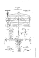
- FIG. 1 is aside elevation of the gate closed.
- Fig. 2 is a front elevation of the gate'open, with the levers broken away between their ends.
- Fig, 4 is an elevationof the front, gate posts. viewed from a. point; to the right-handof them as they appear in Fig. 1, and they are broken away between their ends.
- F ig, 5 is a vertical. section on the line 5,5 of Fig. 4, but with the gate in place and closed with the latch pulled back so that the gate is ready to be raisedand opened.
- F ig. 6 is a. section on the line 66 of Fig. 1.
- -Fig. 7 isa sec-i tion on the line 7,7 of. Fig. 1.
- FIG. 1 shows a. gate 10 of ordinary construction vso that the details thereof need not here be set forth.
- a pair of parallelv rear gate posts 11 which are spaced. apart, substantially as shown in Fig, 2, and which are not connected. with, each other from top to bottom.
- There is a pair of front gate posts 12 which are con nected between. their ends by a cross latch. bar 13on. the outside or right-hand side, as shown inFig. 1, so that there will be left ample room between the front posts for the front end of; the gate to settle in.
- connection 14 at the bottom of the front gate posts and located between them to support the front end. of the gate when it is closed.
- the upper ends of the front posts are. beveled at their inner corners to facilitate the guiding of the front part of the gate in between said posts when the gate is being closed.
- the gate has secured to each side thereof at. its lower rearcorner a metal plate 15 which is shownhere to be rectangular, and a fulcrum pin,16 extends through both metal plates and the intermediate gate and is mounted in arms 17 extending from the rear posts inward, as shown in Fig. 1.
- a metal plate 15 which is shownhere to be rectangular
- a fulcrum pin,16 extends through both metal plates and the intermediate gate and is mounted in arms 17 extending from the rear posts inward, as shown in Fig. 1.
- This is. the only fulcrum of the gate or only point where the gateis fulcrumed or connected with the. gate posts.
- the gate is hinged or.- connectedwiththe gate posts near their upper ends, any leaning of the posts will cause the gate to drag badly at the front end so that it can hardly be opened or it will otherwise shift the position of the gate in closing and opening so that it is difiicult to operate the same.
- the difficulty referred to is entirely obviated or neglig
- the gate is mounted as has been explained so that it can be upsended or turned up rearward between the rear gate posts, as shown in Figs. 2' and 3, turning on its fulcrum 16'and' after the center of gravity of the gate while opening has passed over the fulcrum 16, the weight of the gatewill hold it open, as shown in Fig. 3.
- the means for operating the gate consists of levers 20 extending in opposite directions from the rear gate posts and the gate, as
- the lever 20 is fulcrumed on a pin 21 which is mounted in a horizontally extending metal bar 22 secured to the inner face of the post 11 near its upper end and projecting outwardly and said pivot pin 21 is mounted also in the upper end of a diagonal brace 23 which is connected with the post below the top thereof, as shown in Fig. 2.
- the lever 20 is fulcrumed between its ends for the purpose of giving to the inner end thereof vertical movement to op erate to a sufficient extent the connections between the levers and the gate.
- This OOH. nection consists of an eye bolt 24 secured to and extending downward from the inner end of the lever, a'rod or section 25 pivoted thereto at its upper end and at its lower end pivoted to the end of a movable arm 26 which at its other end at 27 is pivotallyv mounted on the gate posts so as to oscillate vertically.
- a pin 29 which is secured to the plate '15 on the gate at several inches distant to on the gate when the outer end of one of the levers 20 is depressed or pulled .downward.
- the pin 29 is also located on a,
- the gate is thrown open, it will pass above the plate 16 and toward the rear, as shown a in Fig. 3, and this is for the purpose of en-' abling the gate to be closed by said levers.
- each lever 20 There is a weight 30 mounted by a set screw 31 on each lever 20 on its'ou'ter end and the purpose of this weight is to give regularity to the movement of the gate'and to facilitate the starting of the gate, either to open or close it, and above all to carry the gate across its dead center as it isbeing opened or closed.
- the section 28 of the connection passes over the fulcrum 16 and moves to the somewhat lower position, as shown in Fig. 3, which correspondingly lifts or elevates the outer ends of the levers so as to enable the downward pull of the rope 41 at the outer end of the levers to start the gate on its closing movement and the gate will not close with an accelerating movement, but slowly and regularly because of the weights 30.
- the gate when closed, is maintained upright chiefly by the front gate posts as the front end of the gate stands between those posts while the rear end of the gate does not standbetween the rear posts, although it does stand between the arms 26 and their connection 27 with the gate post which would prevent any appreciable lateral movement of the gate.
- the invention is:
- a gate a pair of rear posts spaced apart, means extending inwardly from the lower part of said posts to which the lower rear corner of the gate post is fulcrumed, a
- lever mounted on the upper part of each rear gate post and extending at a right angle from the gate, a flexible connection between said lever and the gate at a point inside of the fulcrum thereof, and means connected with said gate posts for engaging said connection about midway its length thereof and holding the same at such point inward away from the gate posts.
- a gate a pair of rear posts spaced apart, means extending inwardly from the lower part of said posts to which the lower rear corner of the gate post is fulcrumed, a lever mounted on the upper part of each rear gate post and extending at a right angle from the gate, an arm pivoted to the rear gate posts between their ends and extending inwardly, a connection between said lever and the inner end of said arm, and a connection between the inner end of said arm and the gate at a point inward from the fulcrum of the gate.
Landscapes
- Gates (AREA)
Description
0. L. HUFFMAN.
GATE.
APPLICATION men DEc.l5.1913. 1,153,847., PatentedSept. 14, 1915.
" 2 SHEETS-SHEET 1.
3o Fig-g.-
Fig.%.
WITNESSES:
OPLH L. HUFFMFIN.
mm? W I I W ATTORNEY 0. L. HUFFMAN.
GATE.
APPLICATION FILED DEC. 15. I913.
1 1 53,8470 Patented Sept. 14, 1915.
2 SHEETS-SHEET 2.
Fi .3. 35 3g,
WITNESSES: IN VE/VTOR OWL-H L. HUFFMHM. i// 277%? %TATE% FATENT FFTE OELA L. HUFFMAN, on ALBANY, INDIANA, assrenoa To '1. w; nnnrnn, on oons, MONTANA.
GATE.
Application filed. December 15, 1913.;
The object of this invention is to enable a gate to be opened by up-ending the same instead of oscillating it horizontally or the like, and, to render the opening and closing movement easy and simple for the person operating the gate, and also easy on the gate construction so as not to subject any part to unduestrain or cause the gate to have other than a slow regular movement, whlle either opening or closing. Along with the foregoing is combined means for unlatching the j gate.
The chief feature of. the invention consists in fulcruming the gate at the lower rear, corner thereof so that it. can be up ended and 111. mount ng on the rear posts sultable levers project ng at right angles.
from the gate and connected by suitable means, with the gate near itsv fulcrum, whereby the depression of thelevers will upend the. gate and cause the. connection between the levers and thegate tovpass overv and to the rear of'the fulcrum of the-gate,
whereby the gate will stand@ open andin a substantially vertical position and whereby another movementv of the lever will return the gate toclose the same.
Along with the foregoing is a further. ar.-.
rangement 0f the connection between, the levers and the gate which connectionis di; vided into two sections linked to an arm pivoted to the gate post sothat the section thereof which is. connected with the levers will always be substantially vertical and the deadcenter. as it is opening or. closing Specification of Letters Patent. Patented Sept. 14;, 1.915.
Serial No. 806,840.
and will give to the movement of the gate steadiness and regularity and avoid irregularity and. sudden movements thereof and to keep it, fromclosing with a shock.
The full nature of the invention will be understood from the accompanying drawings and the following description and; clalms. I I
In the drawings,- Figure 1 is aside elevation of the gate closed. Fig. 2 is a front elevation of the gate'open, with the levers broken away between their ends. Fig. 3,.is a side elevation of the gate open. Fig, 4 is an elevationof the front, gate posts. viewed from a. point; to the right-handof them as they appear in Fig. 1, and they are broken away between their ends. F ig, 5 is a vertical. section on the line 5,5 of Fig. 4, but with the gate in place and closed with the latch pulled back so that the gate is ready to be raisedand opened. F ig. 6 is a. section on the line 66 of Fig. 1. -Fig. 7 isa sec-i tion on the line 7,7 of. Fig. 1.
Herein, the drawings show a. gate 10 of ordinary construction vso that the details thereof need not here be set forth. There is a pair of parallelv rear gate posts 11 which are spaced. apart, substantially as shown in Fig, 2, and which are not connected. with, each other from top to bottom. There is a pair of front gate posts 12 which are con nected between. their ends by a cross latch. bar 13on. the outside or right-hand side, as shown inFig. 1, so that there will be left ample room between the front posts for the front end of; the gate to settle in. There. is also a connection 14: at the bottom of the front gate posts and located between them to support the front end. of the gate when it is closed. The upper ends of the front posts, are. beveled at their inner corners to facilitate the guiding of the front part of the gate in between said posts when the gate is being closed.
The gate has secured to each side thereof at. its lower rearcorner a metal plate 15 which is shownhere to be rectangular, and a fulcrum pin,16 extends through both metal plates and the intermediate gate and is mounted in arms 17 extending from the rear posts inward, as shown in Fig. 1. This is. the only fulcrum of the gate or only point where the gateis fulcrumed or connected with the. gate posts. Then the gate is hinged or.- connectedwiththe gate posts near their upper ends, any leaning of the posts will cause the gate to drag badly at the front end so that it can hardly be opened or it will otherwise shift the position of the gate in closing and opening so that it is difiicult to operate the same. But with the one connection-between thegate and rear posts being located near the bottom of said posts where there is appreciably no change of'position due to the posts leaning, the difficulty referred to is entirely obviated or negligible.
The gate is mounted as has been explained so that it can be upsended or turned up rearward between the rear gate posts, as shown in Figs. 2' and 3, turning on its fulcrum 16'and' after the center of gravity of the gate while opening has passed over the fulcrum 16, the weight of the gatewill hold it open, as shown in Fig. 3.
The means for operating the gate consists of levers 20 extending in opposite directions from the rear gate posts and the gate, as
shown in Fig. 2. There is one lever ful crumed to the upper part of each rear gate post and both levers are similarly made and mounted and connected with the gate so that either one can be used to operatethe gate, depending upon the direction one approaches the gate. These levers extend beside the roadway. I
The lever 20 is fulcrumed on a pin 21 which is mounted in a horizontally extending metal bar 22 secured to the inner face of the post 11 near its upper end and projecting outwardly and said pivot pin 21 is mounted also in the upper end of a diagonal brace 23 which is connected with the post below the top thereof, as shown in Fig. 2.
Therefore, the lever 20 is fulcrumed between its ends for the purpose of giving to the inner end thereof vertical movement to op erate to a sufficient extent the connections between the levers and the gate. This OOH. nection consists of an eye bolt 24 secured to and extending downward from the inner end of the lever, a'rod or section 25 pivoted thereto at its upper end and at its lower end pivoted to the end of a movable arm 26 which at its other end at 27 is pivotallyv mounted on the gate posts so as to oscillate vertically.
end to a pin 29 which is secured to the plate '15 on the gate at several inches distant to on the gate when the outer end of one of the levers 20 is depressed or pulled .downward. The pin 29 is also located on a,
higher plane than'the pivot 16 so that when The connection is completed by the lower section 28 which is pivoted at its upper end to said arm 26 and at its lower.
the gate is thrown open, it will pass above the plate 16 and toward the rear, as shown a in Fig. 3, and this is for the purpose of en-' abling the gate to be closed by said levers.
It is to be noted that by using the arm 26,
the upper section 25 of said connection does not change. position very much, but pulls, on the'lever in substantially the same direc- Also this arm 26 changesapprehas considerable vibratory movementfrom the position shown in Fig. 1 to that shown in Fig. 3, and that movement passes over the fulcrum 16 and thus gives correspondingly greater annular pull in starting the gate, either to open or close it.
There is a weight 30 mounted by a set screw 31 on each lever 20 on its'ou'ter end and the purpose of this weight is to give regularity to the movement of the gate'and to facilitate the starting of the gate, either to open or close it, and above all to carry the gate across its dead center as it isbeing opened or closed.
W' hen the gate is closed, it is latched by a spring latch 35 which'is secured at 36 to the front part of the gate, as shownin Fig. 5, in position to engage or catch under the It is ro catch bar 13 on the front posts. leased by a wire 37 which is connected to the upper end of the latch so as to draw it in-- ioo ward and said wire extends to a bell crank lever 38 .fulcrumed at 39 inarms 410 secured and extending from one of the longitudinal bars of the gate, as shown in Fig. 1. The other end of the bell crank lever is connected with a rope 41 which passes through the eye 24 at the inner end of the lever and over apulley 42 at the outer end of the lever and hence down fromthe lever to render accessible. is
When one approaches the gate, he pulls. down on the outerend' ofthe rope 11 which withdraws the latch, as shown in Fig. 5, and releases it; Further downward pull-on'said rope 4:1 draws downward the outer end of the lever 20 and up-ends the gate, moving it to the position shown in Figs. 2'and 3.
I With the weights 3O properly adjusted sub stantially the same pull necessary'to unlatch the gate will up-end it and as the gate approaches the dead center, or vertical position, the weights 30 will cause it to continue its movement past the dead center when said weights will retard its movement, due
to gravity and also the gate to come to rest in the entirely open position shown in Fig. 3, upon a block 4 1. It remains in that position by gravity until a person pulls down on the cord 41 depending from the end of a lever 20 and that throws the gate back from the open position shown in Fig. 3 to that shown in Fig. 1.
As the gate opens and settles back to the position shown in Fig. 3, the section 28 of the connection passes over the fulcrum 16 and moves to the somewhat lower position, as shown in Fig. 3, which correspondingly lifts or elevates the outer ends of the levers so as to enable the downward pull of the rope 41 at the outer end of the levers to start the gate on its closing movement and the gate will not close with an accelerating movement, but slowly and regularly because of the weights 30. The gate, when closed, is maintained upright chiefly by the front gate posts as the front end of the gate stands between those posts while the rear end of the gate does not standbetween the rear posts, although it does stand between the arms 26 and their connection 27 with the gate post which would prevent any appreciable lateral movement of the gate.
The invention is:
1. A gate, a pair of rear posts spaced apart, means extending inwardly from the lower part of said posts to which the lower rear corner of the gate post is fulcrumed, a
lever mounted on the upper part of each rear gate post and extending at a right angle from the gate, a flexible connection between said lever and the gate at a point inside of the fulcrum thereof, and means connected with said gate posts for engaging said connection about midway its length thereof and holding the same at such point inward away from the gate posts.
2. A gate, a pair of rear posts spaced apart, means extending inwardly from the lower part of said posts to which the lower rear corner of the gate post is fulcrumed, a lever mounted on the upper part of each rear gate post and extending at a right angle from the gate, an arm pivoted to the rear gate posts between their ends and extending inwardly, a connection between said lever and the inner end of said arm, and a connection between the inner end of said arm and the gate at a point inward from the fulcrum of the gate.
In witness whereof, I have hereunto affixed my signature in the presence of the witnesses herein named.
ORLA L. HUFFMAN.
l/Vitnesses:
J. H. WELLS, O. M. MCLAUGHLIN.
Copies of this patent may be obtained for five cents each, by addressing the Commissioner of Patents, Washington, D. G.
Priority Applications (1)
| Application Number | Priority Date | Filing Date | Title |
|---|---|---|---|
| US80684013A US1153847A (en) | 1913-12-15 | 1913-12-15 | Gate. |
Applications Claiming Priority (1)
| Application Number | Priority Date | Filing Date | Title |
|---|---|---|---|
| US80684013A US1153847A (en) | 1913-12-15 | 1913-12-15 | Gate. |
Publications (1)
| Publication Number | Publication Date |
|---|---|
| US1153847A true US1153847A (en) | 1915-09-14 |
Family
ID=3221915
Family Applications (1)
| Application Number | Title | Priority Date | Filing Date |
|---|---|---|---|
| US80684013A Expired - Lifetime US1153847A (en) | 1913-12-15 | 1913-12-15 | Gate. |
Country Status (1)
| Country | Link |
|---|---|
| US (1) | US1153847A (en) |
Cited By (2)
| Publication number | Priority date | Publication date | Assignee | Title |
|---|---|---|---|---|
| US3828475A (en) * | 1972-10-06 | 1974-08-13 | P Eblen | Gate opener |
| US20040078934A1 (en) * | 2002-10-28 | 2004-04-29 | Feliz Merry L. | Decorative gate handle pulling devices |
-
1913
- 1913-12-15 US US80684013A patent/US1153847A/en not_active Expired - Lifetime
Cited By (3)
| Publication number | Priority date | Publication date | Assignee | Title |
|---|---|---|---|---|
| US3828475A (en) * | 1972-10-06 | 1974-08-13 | P Eblen | Gate opener |
| US20040078934A1 (en) * | 2002-10-28 | 2004-04-29 | Feliz Merry L. | Decorative gate handle pulling devices |
| US6757941B2 (en) * | 2002-10-28 | 2004-07-06 | Merry L. Feliz | Decorative gate handle pulling devices |
Similar Documents
| Publication | Publication Date | Title |
|---|---|---|
| US1153847A (en) | Gate. | |
| US792968A (en) | Gate. | |
| US798846A (en) | Gate. | |
| US553142A (en) | ung-ee | |
| US587563A (en) | terpening | |
| US1102578A (en) | Farm-gate. | |
| US673134A (en) | Gate. | |
| US1171004A (en) | Operating device for sliding doors. | |
| US1095924A (en) | Gate. | |
| US569269A (en) | Automatic gate | |
| US1084733A (en) | Farm-gate. | |
| US726396A (en) | Farm-gate. | |
| US897949A (en) | Gate. | |
| US595377A (en) | L duncan | |
| US784404A (en) | Gate. | |
| US940306A (en) | Gate-operating attachment. | |
| US883960A (en) | Gate-hinge. | |
| US422491A (en) | Farm-gate | |
| US762057A (en) | Gate. | |
| US506213A (en) | Gate-closer | |
| USRE11452E (en) | Safety device for elevators | |
| US844859A (en) | Gate. | |
| US615950A (en) | Robert k barger | |
| US194889A (en) | Improvement in gates | |
| US902874A (en) | Farm-gate. |