US11314788B2 - Smart entity management for building management systems - Google Patents
Smart entity management for building management systems Download PDFInfo
- Publication number
- US11314788B2 US11314788B2 US16/142,803 US201816142803A US11314788B2 US 11314788 B2 US11314788 B2 US 11314788B2 US 201816142803 A US201816142803 A US 201816142803A US 11314788 B2 US11314788 B2 US 11314788B2
- Authority
- US
- United States
- Prior art keywords
- data
- entity
- entities
- building
- objects
- Prior art date
- Legal status (The legal status is an assumption and is not a legal conclusion. Google has not performed a legal analysis and makes no representation as to the accuracy of the status listed.)
- Active, expires
Links
Images


Classifications
-
- G—PHYSICS
- G06—COMPUTING OR CALCULATING; COUNTING
- G06F—ELECTRIC DIGITAL DATA PROCESSING
- G06F16/00—Information retrieval; Database structures therefor; File system structures therefor
- G06F16/20—Information retrieval; Database structures therefor; File system structures therefor of structured data, e.g. relational data
- G06F16/28—Databases characterised by their database models, e.g. relational or object models
- G06F16/284—Relational databases
- G06F16/288—Entity relationship models
-
- G—PHYSICS
- G05—CONTROLLING; REGULATING
- G05B—CONTROL OR REGULATING SYSTEMS IN GENERAL; FUNCTIONAL ELEMENTS OF SUCH SYSTEMS; MONITORING OR TESTING ARRANGEMENTS FOR SUCH SYSTEMS OR ELEMENTS
- G05B15/00—Systems controlled by a computer
- G05B15/02—Systems controlled by a computer electric
-
- G—PHYSICS
- G05—CONTROLLING; REGULATING
- G05B—CONTROL OR REGULATING SYSTEMS IN GENERAL; FUNCTIONAL ELEMENTS OF SUCH SYSTEMS; MONITORING OR TESTING ARRANGEMENTS FOR SUCH SYSTEMS OR ELEMENTS
- G05B19/00—Programme-control systems
- G05B19/02—Programme-control systems electric
- G05B19/04—Programme control other than numerical control, i.e. in sequence controllers or logic controllers
- G05B19/042—Programme control other than numerical control, i.e. in sequence controllers or logic controllers using digital processors
-
- G—PHYSICS
- G06—COMPUTING OR CALCULATING; COUNTING
- G06F—ELECTRIC DIGITAL DATA PROCESSING
- G06F16/00—Information retrieval; Database structures therefor; File system structures therefor
- G06F16/20—Information retrieval; Database structures therefor; File system structures therefor of structured data, e.g. relational data
- G06F16/22—Indexing; Data structures therefor; Storage structures
- G06F16/2228—Indexing structures
-
- G—PHYSICS
- G05—CONTROLLING; REGULATING
- G05B—CONTROL OR REGULATING SYSTEMS IN GENERAL; FUNCTIONAL ELEMENTS OF SUCH SYSTEMS; MONITORING OR TESTING ARRANGEMENTS FOR SUCH SYSTEMS OR ELEMENTS
- G05B2219/00—Program-control systems
- G05B2219/20—Pc systems
- G05B2219/26—Pc applications
- G05B2219/2614—HVAC, heating, ventillation, climate control
-
- G—PHYSICS
- G05—CONTROLLING; REGULATING
- G05B—CONTROL OR REGULATING SYSTEMS IN GENERAL; FUNCTIONAL ELEMENTS OF SUCH SYSTEMS; MONITORING OR TESTING ARRANGEMENTS FOR SUCH SYSTEMS OR ELEMENTS
- G05B2219/00—Program-control systems
- G05B2219/20—Pc systems
- G05B2219/26—Pc applications
- G05B2219/2642—Domotique, domestic, home control, automation, smart house
Definitions
- a building management system is, in general, a system of devices configured to control, monitor, and manage equipment in or around a building or building area.
- a BMS can include, for example, a HVAC system, a security system, a lighting system, a fire alerting system, any other system that is capable of managing building functions or devices, or any combination thereof.
- a BMS can collect data from objects associated with a building, such as other BMSs, building subsystems, devices, sensors and other types of building equipment. Building management platforms are utilized to register and manage the objects, gather and analyze data produced by the objects, and provide recommendations or results based on the collected data. As the number of buildings transitioning to a smart building environment increases, the amount of data being produced and collected has been increasing exponentially. Accordingly, effective analysis of a plethora of collected data is desired.
- a building management cloud computing system for managing data relating to a plurality of objects associated with one or more buildings, the plurality of objects each representing a space, person, building subsystem, and/or device connected to one or more electronic communications networks, includes: one or more processors; and one or more computer-readable storage media communicably coupled to the one or more processors having instructions stored thereon that, when executed by the one or more processors, cause the one or more processors to: generate a database of interconnected smart entities, the smart entities including object entities representing each of the plurality of objects and data entities representing data generated by the objects, the smart entities being interconnected by relational objects indicating relationships between the object entities and the data entities; receive data from a first object of the plurality of objects; determine a second object from a relational object for the first object based on the received data; and modify a data entity connected to an object entity of the second object within the database of smart entities based on the received data for the first object.
- the first object may be a sensor and the second object may be a space within the building in which the sensor is located.
- the senor may be a temperature sensor and the data entity connected to the object entity representing the space may be configured to store an ambient temperature value of the space based on the received data from the temperature sensor.
- the instructions may further cause the one or more processors to create a shadow entity to store historical values of the data entity connected to the object entity representing the space.
- the instructions may further cause the one or more processors to calculate an average ambient temperature value from the historical values stored in the shadow entity.
- the instructions may further cause the one or more processors to calculate an abnormal ambient temperature value from the historical values stored in the shadow entity.
- each of the object entities may include a static attribute to identify the object entity, a dynamic attribute to store a data point associated with the object entity that changes over time, and a behavioral attribute that defines an expected response of the object entity in response to an input.
- the data entity connected to the object entity of the second object may be configured to store the dynamic attribute of the object entity.
- a relational object may semantically define the connection between the data entity and the object entity of the second object.
- the modifying of the data entity connected to the object entity of the second object may include: identifying a dynamic attribute in the data that is associated with the object entity of the second object; determining a relational object connecting the data entity to the object entity of the second object; and storing a value of the data corresponding to the dynamic attribute in the data entity.
- the first object may be an access control device and the second object may be a person associated with the building in which the access control device is located.
- the data entity connected to the object entity representing the person may be configured to store a location attribute of the person based on the received data from the access control device.
- the instructions may further cause the one or more processors to create a shadow entity to store historical values of the received data from the access control device, and to calculate an average arrival time of the person from the historical values stored in the shadow entity.
- a method for managing data relating to a plurality objects associated with one or more buildings, the plurality of objects each representing a space, person, building subsystem, and/or device connected to one or more electronic communications networks includes: generating, by one or more processors, a database of interconnected smart entities, the smart entities including object entities representing each of the plurality of objects and data entities representing data generated by the objects, the smart entities being interconnected by relational objects indicating relationships between the object entities and the data entities; receiving, by the one or more processors, data from a first object of the plurality of objects; determining, by the one or more processors, a second object from a relational object for the first object based on the received data; and modifying, by the one or more processors, a data entity connected to an object entity of the second object within the database of smart entities based on the received data for the first object.
- the first object may be a sensor and the second object may be a space within the building in which the sensor is located.
- the senor may be a temperature sensor and the data entity connected to the object entity representing the space may be configured to store an ambient temperature value of the space based on the received data from the temperature sensor.
- the method may further include creating, by the one or more processors, a shadow entity to store historical values of the data entity connected to the object entity representing the space.
- the method may further include calculating, by the one or more processors, an average ambient temperature value from the historical values stored in the shadow entity.
- the method may further include calculating, by the one or more processors, an abnormal ambient temperature value from the historical values stored in the shadow entity.
- each of the object entities may include a static attribute to identify the object entity, a dynamic attribute to store a data point associated with the object entity that changes over time, and a behavioral attribute that defines an expected response of the object entity in response to an input.
- the data entity connected to the object entity of the second object may be configured to store the dynamic attribute of the object entity.
- a relational object may semantically define the connection between the data entity and the object entity of the second object.
- the modifying of the data entity connected to the object entity of the second object may include: identifying, by the one or more processors, a dynamic attribute in the data that is associated with the object entity of the second object; determining, by the one or more processors, a relational object connecting the data entity to the object entity of the second object; and storing, by the one or more processors, a value of the data corresponding to the dynamic attribute in the data entity.
- the first object may be an access control device and the second object may be a person associated with the building in which the access control device is located.
- the data entity connected to the object entity representing the person may be configured to store a location attribute of the person based on the received data from the access control device.
- the method may further include: creating, by the one or more processors, a shadow entity to store historical values of the received data from the access control device, and calculating, by the one or more processors, an average arrival time of the person from the historical values stored in the shadow entity.
- a non-transient computer readable medium contains program instructions for causing a computer to perform the method of: generating a database of interconnected smart entities, the smart entities including object entities representing each of a plurality of objects associated with one or more buildings and the plurality of objects each representing a space, person, building subsystem, and/or device, and data entities representing data generated by the objects, the smart entities being interconnected by relational objects indicating relationships between the object entities and the data entities; receiving data from a first object of the plurality of objects; determining a second object from a relational object for the first object based on the received data; and modifying a data entity connected to an object entity of the second object within the database of smart entities based on the received data for the first object.
- the first object may be a sensor and the second object may be a space within the building in which the sensor is located.
- the senor may be a temperature sensor and the data entity connected to the object entity representing the space may be configured to store an ambient temperature value of the space based on the received data from the temperature sensor.
- the program instructions may further cause the one or more processors to perform operations including creating a shadow entity to store historical values of the data entity connected to the object entity representing the space.
- the program instructions may further cause the one or more processors to perform operations including calculating an average ambient temperature value from the historical values stored in the shadow entity.
- the program instructions may further cause the one or more processors to perform operations including calculating an abnormal ambient temperature value from the historical values stored in the shadow entity.
- each of the object entities may include a static attribute to identify the object entity, a dynamic attribute to store a data point associated with the object entity that changes over time, and a behavioral attribute that defines an expected response of the object entity in response to an input.
- the data entity connected to the object entity of the second object may be configured to store the dynamic attribute of the object entity.
- a relational object may semantically define the connection between the data entity and the object entity of the second object.
- the modifying of the data entity connected to the object entity of the second object may include: identifying a dynamic attribute in the data that is associated with the object entity of the second object; determining a relational object connecting the data entity to the object entity of the second object; and storing a value of the data corresponding to the dynamic attribute in the data entity.
- the first object may be an access control device and the second object may be a person associated with the building in which the access control device is located.
- the data entity connected to the object entity representing the person may be configured to store a location attribute of the person based on the received data from the access control device.
- the program instructions may further cause the one or more processors to perform operations including creating a shadow entity to store historical values of the received data from the access control device, and calculating an average arrival time of the person from the historical values stored in the shadow entity.
- FIG. 1 Another implementation of the present disclosure is a building management cloud computing system for managing data relating to a plurality of objects associated with one or more buildings, the plurality of objects each representing a space, person, building subsystem, and/or device connected to one or more electronic communications networks.
- the system includes one or more processors and one or more computer-readable storage media communicably coupled to the one or more processors having instructions stored thereon that, when executed by the one or more processors, cause the one or more processors to generate a database of interconnected smart entities.
- the smart entities include object entities representing each of the plurality objects and data entities representing data generated by the objects, the smart entities being interconnected by relational objects indicating relationships between the object entities and the data entities.
- the instructions cause the one or more processors to receive new data from a first object of the plurality of objects; determine whether the database includes a first object entity representing the first object; in response to a determination that the database includes the first object entity, determine whether the database includes a first data entity representing data received from the first object; and in response to a determination that the database includes the first data entity, update an attribute of the first data entity using the new data received from the first object.
- the instructions in response to a determination that the database does not include the first data entity, the instructions further cause the one or more processors to create the first data entity, create a first relational object defining a relationship between the first object entity and the first data entity, and create an attribute of the first data entity and generate a value for the attribute of the first data entity using the new data received from the first object.
- the instructions in response to a determination that the database does not include the first object entity, the instructions further cause the one or more processors to create the first object entity, create the first data entity, create a first relational object defining a relationship between the first object entity and the first data entity, and create an attribute of the first data entity and generate a value for the attribute of the first data entity using the new data received from the first object.
- determining whether the database includes the first object entity includes reading one or more static attributes of the object entities and determining whether any of the static attributes identify the first object.
- determining whether the database includes the first data entity includes reading a relational attribute of the first object entity and determining whether the relational attribute identifies the first data entity.
- determining whether the database includes the first data entity includes identifying a first relational object defining a relationship between the first data entity and one or more of the data entities and determining whether the first relational object identifies the first data entity.
- the first data entity includes a static attribute identifying the first data entity and a dynamic attribute comprising one or more dynamic values of the first data entity. Updating the attribute of the first data entity may include updating the one or more dynamic values of the dynamic attribute using the new data received from the first object.
- one or more of the object entities includes a static attribute to identify the object entity, a dynamic attribute to store a data point associated with the object entity that changes over time, and a behavioral attribute that defines an expected response of the object entity in response to an input.
- the first object may be a temperature sensor located in the building.
- the instructions may further cause the one or more processors to create a shadow entity to store historical values of the first data entity using historical data received from the temperature sensor.
- the instructions may further cause the one or more processors to calculate an average temperature value from the historical values stored in the shadow entity.
- the instructions may further cause the one or more processors to calculate an abnormal temperature value from the historical values stored in the shadow entity.
- the first object may be an access control device located in the building, and the first data entity may be related to an access keycard object relating to a person object.
- the instructions may further cause the one or more processors to update a location attribute of the person object according to the new data received from the access control device.
- Another implementation of the present disclosure is a method for managing data relating to a plurality of objects associated with one or more buildings, the plurality of objects each representing a space, person, building subsystem, and/or device connected to one or more electronic communications networks.
- the method includes generating a database of interconnected smart entities.
- the smart entities include object entities representing each of the plurality of objects and data entities representing data generated by the objects, the smart entities being interconnected by relational objects indicating relationships between the object entities and the data entities.
- the method includes receiving new data from a first object of the plurality of objects; determining whether the database includes a first object entity representing the first object; in response to a determination that the database includes the first object entity, determining whether the database includes a first data entity representing data received from the first object; and in response to a determination that the database includes the first data entity, updating an attribute of the first data entity using the new data received from the first object.
- the method in response to a determination that the database does not include the first data entity, the method comprises creating the first data entity, creating a first relational object defining a relationship between the first object entity and the first data entity, and creating an attribute of the first data entity and generating a value for the attribute of the first data entity using the new data received from the first object.
- the method in response to a determination that the database does not include the first object entity, the method comprises creating the first object entity, creating the first data entity, creating a first relational object defining a relationship between the first object entity and the first data entity, and creating an attribute of the first data entity and generating a value for the attribute of the first data entity using the new data received from the first object.
- determining whether the database includes the first object entity includes reading one or more static attributes of the object entities and determining whether any of the static attributes identify the first object.
- determining whether the database includes the first data entity includes reading a relational attribute of the first object entity and determining whether the relational attribute identifies the first data entity.
- determining whether the database includes the first data entity includes identifying a first relational object defining a relationship between the first data entity and one or more of the data entities and determining whether the first relational object identifies the first data entity.
- the first data entity includes a static attribute identifying the first data entity and a dynamic attribute comprising one or more dynamic values of the first data entity. Updating the attribute of the first data entity may include updating the one or more dynamic values of the dynamic attribute using the new data received from the first object.
- one or more of the object entities includes a static attribute to identify the object entity, a dynamic attribute to store a data point associated with the object entity that changes over time, and a behavioral attribute that defines an expected response of the object entity in response to an input.
- the first object may be a temperature sensor located in the building.
- the method may further include creating a shadow entity to store historical values of the first data entity using historical data received from the temperature sensor.
- the method may further include calculating an average temperature value from the historical values stored in the shadow entity.
- the method may further include calculating an abnormal temperature value from the historical values stored in the shadow entity.
- the first object may be an access control device located in the building, and the first data entity may be related to an access keycard object relating to a person object.
- the method may further include updating a location attribute of the person object according to the new data received from the access control device.
- Another implementation of the present disclosure is one or more non-transitory computer readable media containing program instructions that, when executed by one or more processors, cause the one or more processors to perform operations including generating a database of interconnected smart entities.
- the smart entities include object entities representing each of a plurality of objects associated with one or more buildings and the plurality of objects each representing a space, person, building subsystem, and/or device, and data entities representing data generated by the objects, the smart entities being interconnected by relational objects indicating relationships between the object entities and the data entities.
- the operations include receiving new data from a first object of the plurality of objects; determining whether the database includes a first object entity representing the first object; in response to a determination that the database includes the first object entity, determining whether the database includes a first data entity representing data received from the first object; and in response to a determination that the database includes the first data entity, updating an attribute of the first data entity using the new data received from the first object.
- the instructions in response to a determination that the database does not include the first data entity, the instructions further cause the one or more processors to create the first data entity, create a first relational object defining a relationship between the first object entity and the first data entity, and create an attribute of the first data entity and generate a value for the attribute of the first data entity using the new data received from the first object.
- the instructions in response to a determination that the database does not include the first object entity, the instructions further cause the one or more processors to create the first object entity, create the first data entity, create a first relational object defining a relationship between the first object entity and the first data entity, and create an attribute of the first data entity and generate a value for the attribute of the first data entity using the new data received from the first object.
- determining whether the database includes the first object entity includes reading one or more static attributes of the object entities and determining whether any of the static attributes identify the first object.
- determining whether the database includes the first data entity includes reading a relational attribute of the first object entity and determining whether the relational attribute identifies the first data entity.
- determining whether the database includes the first data entity includes identifying a first relational object defining a relationship between the first data entity and one or more of the data entities and determining whether the first relational object identifies the first data entity.
- the first data entity includes a static attribute identifying the first data entity and a dynamic attribute comprising one or more dynamic values of the first data entity. Updating the attribute of the first data entity may include updating the one or more dynamic values of the dynamic attribute using the new data received from the first object.
- one or more of the object entities includes a static attribute to identify the object entity, a dynamic attribute to store a data point associated with the object entity that changes over time, and a behavioral attribute that defines an expected response of the object entity in response to an input.
- the first object may be a temperature sensor located in the building.
- the instructions may further cause the one or more processors to create a shadow entity to store historical values of the first data entity using historical data received from the temperature sensor.
- the instructions may further cause the one or more processors to calculate an average temperature value from the historical values stored in the shadow entity.
- the instructions may further cause the one or more processors to calculate an abnormal temperature value from the historical values stored in the shadow entity.
- the first object may be an access control device located in the building, and the first data entity may be related to an access keycard object relating to a person object.
- the instructions may further cause the one or more processors to update a location attribute of the person object according to the new data received from the access control device.
- FIG. 1 is a block diagram of a smart building environment, according to some exemplary embodiments
- FIG. 2 is a perspective view of a smart building, according to some exemplary embodiments.
- FIG. 3 is a block diagram of a waterside system, according to some exemplary embodiments.
- FIG. 4 is a block diagram of an airside system, according to some exemplary embodiments.
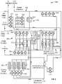
- FIG. 5 is a block diagram of a building management system, according to some exemplary embodiments.
- FIG. 6 is a block diagram of another building management system, according to some exemplary embodiments.
- FIG. 7 is a block diagram illustrating an entity service of FIG. 6 in greater detail, according to some exemplary embodiments.
- FIG. 8 in an example entity graph of entity data, according to some embodiments.
- FIG. 9 is a flow diagram of a process or method for updating/creating an attribute of a related entity based on data received from a device of a building management subsystem, according to some exemplary embodiments;
- FIG. 10 is an example entity graph of entity data, according to some exemplary embodiments.
- FIG. 11 is a flow diagram of a process or method for analyzing data from a second related device based on data from a first device, according to some exemplary embodiments.
- FIG. 1 is a block diagram of a smart building environment 100 , according to some exemplary embodiments.
- Smart building environment 100 is shown to include a building management platform 102 .
- Building management platform 102 can be configured to collect data from a variety of different data sources.
- building management platform 102 is shown collecting data from buildings 110 , 120 , 130 , and 140 .
- the buildings may include a school 110 , a hospital 120 , a factory 130 , an office building 140 , and/or the like.
- the present disclosure is not limited to the number or types of buildings 110 , 120 , 130 , and 140 shown in FIG. 1 .
- building management platform 102 may be configured to collect data from one or more buildings, and the one or more buildings may be the same type of building or may include one or more different types of buildings than that shown in FIG. 1 .
- Building management platform 102 can be configured to collect data from a variety of devices 112 - 116 , 122 - 126 , 132 - 136 , and 142 - 146 , either directly (e.g., directly via network 104 ) or indirectly (e.g., via systems or applications in the buildings 110 , 120 , 130 , 140 ).
- devices 112 - 116 , 122 - 126 , 132 - 136 , and 142 - 146 are internet of things (IoT) devices.
- IoT devices may include any of a variety of physical devices, sensors, actuators, electronics, vehicles, home appliances, and/or other items having network connectivity which enable IoT devices to communicate with building management platform 102 .
- IoT devices can include smart home hub devices, smart house devices, doorbell cameras, air quality sensors, smart switches, smart lights, smart appliances, garage door openers, smoke detectors, heart monitoring implants, biochip transponders, cameras streaming live feeds, automobiles with built-in sensors, DNA analysis devices, field operation devices, tracking devices for people/vehicles/equipment, networked sensors, wireless sensors, wearable sensors, environmental sensors, RFID gateways and readers, IoT gateway devices, robots and other robotic devices, GPS devices, smart watches, virtual/augmented reality devices, and/or other networked or networkable devices. While the devices described herein are generally referred to as IoT devices, it should be understood that, in various embodiments, the devices referenced in the present disclosure could be any type of devices capable of communicating data over an electronic network.
- IoT devices may include sensors or sensor systems.
- IoT devices may include acoustic sensors, sound sensors, vibration sensors, automotive or transportation sensors, chemical sensors, electric current sensors, electric voltage sensors, magnetic sensors, radio sensors, environment sensors, weather sensors, moisture sensors, humidity sensors, flow sensors, fluid velocity sensors, ionizing radiation sensors, subatomic particle sensors, navigation instruments, position sensors, angle sensors, displacement sensors, distance sensors, speed sensors, acceleration sensors, optical sensors, light sensors, imaging devices, photon sensors, pressure sensors, force sensors, density sensors, level sensors, thermal sensors, heat sensors, temperature sensors, proximity sensors, presence sensors, and/or any other type of sensors or sensing systems.
- Examples of acoustic, sound, or vibration sensors include geophones, hydrophones, lace sensors, guitar pickups, microphones, and seismometers.
- Examples of automotive or transportation sensors include air flow meters, air-fuel ratio meters, AFR sensors, blind spot monitors, crankshaft position sensors, defect detectors, engine coolant temperature sensors, Hall effect sensors, knock sensors, map sensors, mass flow sensors, oxygen sensors, parking sensors, radar guns, speedometers, speed sensors, throttle position sensors, tire-pressure monitoring sensors, torque sensors, transmission fluid temperature sensors, turbine speed sensors, variable reluctance sensors, vehicle speed sensors, water sensors, and wheel speed sensors.
- Examples of chemical sensors include breathalyzers, carbon dioxide sensors, carbon monoxide detectors, catalytic bead sensors, chemical field-effect transistors, chemiresistors, electrochemical gas sensors, electronic noses, electrolyte-insulator-semiconductor sensors, fluorescent chloride sensors, holographic sensors, hydrocarbon dew point analyzers, hydrogen sensors, hydrogen sulfide sensors, infrared point sensors, ion-selective electrodes, nondispersive infrared sensors, microwave chemistry sensors, nitrogen oxide sensors, olfactometers, optodes, oxygen sensors, ozone monitors, pellistors, pH glass electrodes, potentiometric sensors, redox electrodes, smoke detectors, and zinc oxide nanorod sensors.
- electromagnetic sensors include current sensors, Daly detectors, electroscopes, electron multipliers, Faraday cups, galvanometers, Hall effect sensors, Hall probes, magnetic anomaly detectors, magnetometers, magnetoresistances, mems magnetic field sensors, metal detectors, planar hall sensors, radio direction finders, and voltage detectors.
- Examples of environmental sensors include actinometers, air pollution sensors, bedwetting alarms, ceilometers, dew warnings, electrochemical gas sensors, fish counters, frequency domain sensors, gas detectors, hook gauge evaporimeters, humistors, hygrometers, leaf sensors, lysimeters, pyranometers, pyrgeometers, psychrometers, rain gauges, rain sensors, seismometers, SNOTEL sensors, snow gauges, soil moisture sensors, stream gauges, and tide gauges.
- Examples of flow and fluid velocity sensors include air flow meters, anemometers, flow sensors, gas meter, mass flow sensors, and water meters.
- Examples of radiation and particle sensors include cloud chambers, Geiger counters, Geiger-Muller tubes, ionisation chambers, neutron detections, proportional counters, scintillation counters, semiconductor detectors, and thermoluminescent dosimeters.
- Examples of navigation instruments include air speed indicators, altimeters, attitude indicators, depth gauges, fluxgate compasses, gyroscopes, inertial navigation systems, inertial reference nits, magnetic compasses, MHD sensors, ring laser gyroscopes, turn coordinators, tialinx sensors, variometers, vibrating structure gyroscopes, and yaw rate sensors.
- position, angle, displacement, distance, speed, and acceleration sensors examples include auxanometers, capacitive displacement sensors, capacitive sensing devices, flex sensors, free fall sensors, gravimeters, gyroscopic sensors, impact sensors, inclinometers, integrated circuit piezoelectric sensors, laser rangefinders, laser surface velocimeters, LIDAR sensors, linear encoders, linear variable differential transformers (LVDT), liquid capacitive inclinometers odometers, photoelectric sensors, piezoelectric accelerometers, position sensors, position sensitive devices, angular rate sensors, rotary encoders, rotary variable differential transformers, selsyns, shock detectors, shock data loggers, tilt sensors, tachometers, ultrasonic thickness gauges, variable reluctance sensors, and velocity receivers.
- auxanometers capacitive displacement sensors, capacitive sensing devices, flex sensors, free fall sensors, gravimeters, gyroscopic sensors, impact sensors, inclinometers, integrated circuit piezoelectric sensors
- optical, light, imaging, and photon sensors examples include charge-coupled devices, CMOS sensors, colorimeters, contact image sensors, electro-optical sensors, flame detectors, infra-red sensors, kinetic inductance detectors, led as light sensors, light-addressable potentiometric sensors, Nichols radiometers, fiber optic sensors, optical position sensors, thermopile laser sensors, photodetectors, photodiodes, photomultiplier tubes, phototransistors, photoelectric sensors, photoionization detectors, photomultipliers, photoresistors, photoswitches, phototubes, scintillometers, Shack-Hartmann sensors, single-photon avalanche diodes, superconducting nanowire single-photon detectors, transition edge sensors, visible light photon counters, and wavefront sensors.
- Examples of pressure sensors include barographs, barometers, boost gauges, bourdon gauges, hot filament ionization gauges, ionization gauges, McLeod gauges, oscillating u-tubes, permanent downhole gauges, piezometers, pirani gauges, pressure sensors, pressure gauges, tactile sensors, and time pressure gauges.
- Examples of force, density, and level sensors include bhangmeters, hydrometers, force gauge and force sensors, level sensors, load cells, magnetic level gauges, nuclear density gauges, piezocapacitive pressure sensors, piezoelectric sensors, strain gauges, torque sensors, and viscometers.
- thermal, heat, and temperature sensors include bolometers, bimetallic strips, calorimeters, exhaust gas temperature gauges, flame detections, Gardon gauges, Golay cells, heat flux sensors, infrared thermometers, microbolometers, microwave radiometers, net radiometers, quartz thermometers, resistance thermometers, silicon bandgap temperature sensors, special sensor microwave/imagers, temperature gauges, thermistors, thermocouples, thermometers, and pyrometers.
- proximity and presence sensors include alarm sensors, Doppler radars, motion detectors, occupancy sensors, proximity sensors, passive infrared sensors, reed switches, stud finders, triangulation sensors, touch switches, and wired gloves.
- different sensors send measurements or other data to building management platform 102 using a variety of different communications protocols or data formats.
- Building management platform 102 can be configured to ingest sensor data received in any protocol or data format and translate the inbound sensor data into a common data format.
- Building management platform 102 can create a sensor object smart entity for each sensor that communicates with Building management platform 102 .
- Each sensor object smart entity may include one or more static attributes that describe the corresponding sensor, one or more dynamic attributes that indicate the most recent values collected by the sensor, and/or one or more relational attributes that relate sensors object smart entities to each other and/or to other types of smart entities (e.g., space entities, system entities, data entities, etc.).
- building management platform 102 stores sensor data using data entities. Each data entity may correspond to a particular sensor and may include a timeseries of data values received from the corresponding sensor.
- building management platform 102 stores relational objects that define relationships between sensor object entities and the corresponding data entity. For example, each relational object may identify a particular sensor object entity, a particular data entity, and may define a link between such entities.
- Building management platform 102 can collect data from a variety of external systems or services. For example, building management platform 102 is shown receiving weather data from a weather service 152 , news data from a news service 154 , documents and other document-related data from a document service 156 , and media (e.g., video, images, audio, social media, etc.) from a media service 158 . In some embodiments, building management platform 102 generates data internally. For example, building management platform 102 may include a web advertising system, a website traffic monitoring system, a web sales system, or other types of platform services that generate data. The data generated by building management platform 102 can be collected, stored, and processed along with the data received from other data sources.
- Building management platform 102 can collect data directly from external systems or devices or via a network 104 (e.g., a WAN, the Internet, a cellular network, etc.). Building management platform 102 can process and transform collected data to generate timeseries data and entity data. Several features of building management platform 102 are described in more detail below.
- a network 104 e.g., a WAN, the Internet, a cellular network, etc.
- FIG. 2 shows a building 10 equipped with, for example, a HVAC system 200 .
- Building 10 may be any of the buildings 210 , 220 , 230 , and 140 as shown in FIG. 1 , or may be any other suitable building that is communicatively connected to building management platform 202 .
- FIG. 3 is a block diagram of a waterside system 300 which can be used to serve building 10 .
- FIG. 4 is a block diagram of an airside system 400 which can be used to serve building 10 .
- FIG. 5 is a block diagram of a building management system (BMS) which can be used to monitor and control building 10 .
- BMS building management system
- a BMS is, in general, a system of devices configured to control, monitor, and manage equipment in or around a building or building area.
- a BMS can include, for example, a HVAC system, a security system, a lighting system, a fire alerting system, any other system that is capable of managing building functions or devices, or any combination thereof.
- each of the systems may include a plurality of sensors and other devices (e.g., IoT devices) for the proper operation, maintenance, monitoring, and the like of the respective systems.
- HVAC system 200 can include a plurality of HVAC devices (e.g., heaters, chillers, air handling units, pumps, fans, thermal energy storage, etc.) configured to provide heating, cooling, ventilation, or other services for building 10 .
- HVAC system 200 is shown to include a waterside system 220 and an airside system 230 .
- Waterside system 220 may provide a heated or chilled fluid to an air handling unit of airside system 230 .
- Airside system 230 may use the heated or chilled fluid to heat or cool an airflow provided to building 10 .
- An exemplary waterside system and airside system which can be used in HVAC system 200 are described in greater detail with reference to FIGS. 3 and 4 .
- HVAC system 200 is shown to include a chiller 202 , a boiler 204 , and a rooftop air handling unit (AHU) 206 .
- Waterside system 220 may use boiler 204 and chiller 202 to heat or cool a working fluid (e.g., water, glycol, etc.) and may circulate the working fluid to AHU 206 .
- the HVAC devices of waterside system 220 can be located in or around building 10 (as shown in FIG. 2 ) or at an offsite location such as a central plant (e.g., a chiller plant, a steam plant, a heat plant, etc.).
- the working fluid can be heated in boiler 204 or cooled in chiller 202 , depending on whether heating or cooling is required in building 10 .
- Boiler 204 may add heat to the circulated fluid, for example, by burning a combustible material (e.g., natural gas) or using an electric heating element.
- Chiller 202 may place the circulated fluid in a heat exchange relationship with another fluid (e.g., a refrigerant) in a heat exchanger (e.g., an evaporator) to absorb heat from the circulated fluid.
- the working fluid from chiller 202 and/or boiler 204 can be transported to AHU 206 via piping 208 .
- AHU 206 may place the working fluid in a heat exchange relationship with an airflow passing through AHU 206 (e.g., via one or more stages of cooling coils and/or heating coils).
- the airflow can be, for example, outside air, return air from within building 10 , or a combination of both.
- AHU 206 may transfer heat between the airflow and the working fluid to provide heating or cooling for the airflow.
- AHU 206 can include one or more fans or blowers configured to pass the airflow over or through a heat exchanger containing the working fluid. The working fluid may then return to chiller 202 or boiler 204 via piping 210 .
- Airside system 230 may deliver the airflow supplied by AHU 206 (i.e., the supply airflow) to building 10 via air supply ducts 212 and may provide return air from building 10 to AHU 206 via air return ducts 214 .
- airside system 230 includes multiple variable air volume (VAV) units 216 .
- VAV units 216 can include dampers or other flow control elements that can be operated to control an amount of the supply airflow provided to individual zones of building 10 .
- airside system 230 delivers the supply airflow into one or more zones of building 10 (e.g., via supply ducts 212 ) without using intermediate VAV units 216 or other flow control elements.
- AHU 206 can include various sensors (e.g., temperature sensors, pressure sensors, etc.) configured to measure attributes of the supply airflow.
- AHU 206 may receive input from sensors located within AHU 206 and/or within the building zone and may adjust the flow rate, temperature, or other attributes of the supply airflow through AHU 206 to achieve setpoint conditions for the building zone.
- waterside system 300 may supplement or replace waterside system 220 in HVAC system 200 or can be implemented separate from HVAC system 200 .
- waterside system 300 can include a subset of the HVAC devices in HVAC system 200 (e.g., boiler 204 , chiller 202 , pumps, valves, etc.) and may operate to supply a heated or chilled fluid to AHU 206 .
- the HVAC devices of waterside system 300 can be located within building 10 (e.g., as components of waterside system 220 ) or at an offsite location such as a central plant.
- waterside system 300 is shown as a central plant having a plurality of subplants 302 - 312 .
- Subplants 302 - 312 are shown to include a heater subplant 302 , a heat recovery chiller subplant 304 , a chiller subplant 306 , a cooling tower subplant 308 , a hot thermal energy storage (TES) subplant 310 , and a cold thermal energy storage (TES) subplant 312 .
- Subplants 302 - 312 consume resources (e.g., water, natural gas, electricity, etc.) from utilities to serve thermal energy loads (e.g., hot water, cold water, heating, cooling, etc.) of a building or campus.
- resources e.g., water, natural gas, electricity, etc.
- thermal energy loads e.g., hot water, cold water, heating, cooling, etc.
- heater subplant 302 can be configured to heat water in a hot water loop 314 that circulates the hot water between heater subplant 302 and building 10 .
- Chiller subplant 306 can be configured to chill water in a cold water loop 316 that circulates the cold water between chiller subplant 306 and building 10 .
- Heat recovery chiller subplant 304 can be configured to transfer heat from cold water loop 316 to hot water loop 314 to provide additional heating for the hot water and additional cooling for the cold water.
- Condenser water loop 318 may absorb heat from the cold water in chiller subplant 306 and reject the absorbed heat in cooling tower subplant 308 or transfer the absorbed heat to hot water loop 314 .
- Hot TES subplant 310 and cold TES subplant 312 may store hot and cold thermal energy, respectively, for subsequent use.
- Hot water loop 314 and cold water loop 316 may deliver the heated and/or chilled water to air handlers located on the rooftop of building 10 (e.g., AHU 206 ) or to individual floors or zones of building 10 (e.g., VAV units 216 ).
- the air handlers push air past heat exchangers (e.g., heating coils or cooling coils) through which the water flows to provide heating or cooling for the air.
- the heated or cooled air can be delivered to individual zones of building 10 to serve thermal energy loads of building 10 .
- the water then returns to subplants 302 - 312 to receive further heating or cooling.
- subplants 302 - 312 are shown and described as heating and cooling water for circulation to a building, it is understood that any other type of working fluid (e.g., glycol, CO2, etc.) can be used in place of or in addition to water to serve thermal energy loads. In other embodiments, subplants 302 - 312 may provide heating and/or cooling directly to the building or campus without requiring an intermediate heat transfer fluid. These and other variations to waterside system 300 are within the teachings of the present disclosure.
- working fluid e.g., glycol, CO2, etc.
- Each of subplants 302 - 312 can include a variety of equipment configured to facilitate the functions of the subplant.
- heater subplant 302 is shown to include a plurality of heating elements 320 (e.g., boilers, electric heaters, etc.) configured to add heat to the hot water in hot water loop 314 .
- Heater subplant 302 is also shown to include several pumps 322 and 324 configured to circulate the hot water in hot water loop 314 and to control the flow rate of the hot water through individual heating elements 320 .
- Chiller subplant 306 is shown to include a plurality of chillers 332 configured to remove heat from the cold water in cold water loop 316 .
- Chiller subplant 306 is also shown to include several pumps 334 and 336 configured to circulate the cold water in cold water loop 316 and to control the flow rate of the cold water through individual chillers 332 .
- Heat recovery chiller subplant 304 is shown to include a plurality of heat recovery heat exchangers 326 (e.g., refrigeration circuits) configured to transfer heat from cold water loop 316 to hot water loop 314 .
- Heat recovery chiller subplant 304 is also shown to include several pumps 328 and 330 configured to circulate the hot water and/or cold water through heat recovery heat exchangers 326 and to control the flow rate of the water through individual heat recovery heat exchangers 326 .
- Cooling tower subplant 308 is shown to include a plurality of cooling towers 338 configured to remove heat from the condenser water in condenser water loop 318 .
- Cooling tower subplant 308 is also shown to include several pumps 340 configured to circulate the condenser water in condenser water loop 318 and to control the flow rate of the condenser water through individual cooling towers 338 .
- Hot TES subplant 310 is shown to include a hot TES tank 342 configured to store the hot water for later use.
- Hot TES subplant 310 may also include one or more pumps or valves configured to control the flow rate of the hot water into or out of hot TES tank 342 .
- Cold TES subplant 312 is shown to include cold TES tanks 344 configured to store the cold water for later use.
- Cold TES subplant 312 may also include one or more pumps or valves configured to control the flow rate of the cold water into or out of cold TES tanks 344 .
- one or more of the pumps in waterside system 300 (e.g., pumps 322 , 324 , 328 , 330 , 334 , 336 , and/or 340 ) or pipelines in waterside system 300 include an isolation valve associated therewith. Isolation valves can be integrated with the pumps or positioned upstream or downstream of the pumps to control the fluid flows in waterside system 300 .
- waterside system 300 can include more, fewer, or different types of devices and/or subplants based on the particular configuration of waterside system 300 and the types of loads served by waterside system 300 .
- airside system 400 may supplement or replace airside system 230 in HVAC system 200 or can be implemented separate from HVAC system 200 .
- airside system 400 can include a subset of the HVAC devices in HVAC system 200 (e.g., AHU 206 , VAV units 216 , ducts 212 - 214 , fans, dampers, etc.) and can be located in or around building 10 .
- Airside system 400 may operate to heat or cool an airflow provided to building 10 using a heated or chilled fluid provided by waterside system 300 .
- airside system 400 is shown to include an economizer-type air handling unit (AHU) 402 .
- Economizer-type AHUs vary the amount of outside air and return air used by the air handling unit for heating or cooling.
- AHU 402 may receive return air 404 from building zone 406 via return air duct 408 and may deliver supply air 410 to building zone 406 via supply air duct 412 .
- AHU 402 is a rooftop unit located on the roof of building 10 (e.g., AHU 206 as shown in FIG. 2 ) or otherwise positioned to receive both return air 404 and outside air 414 .
- AHU 402 can be configured to operate exhaust air damper 416 , mixing damper 418 , and outside air damper 420 to control an amount of outside air 414 and return air 404 that combine to form supply air 410 . Any return air 404 that does not pass through mixing damper 418 can be exhausted from AHU 402 through exhaust damper 416 as exhaust air 422 .
- Each of dampers 416 - 420 can be operated by an actuator.
- exhaust air damper 416 can be operated by actuator 424
- mixing damper 418 can be operated by actuator 426
- outside air damper 420 can be operated by actuator 428 .
- Actuators 424 - 428 may communicate with an AHU controller 430 via a communications link 432 .
- Actuators 424 - 428 may receive control signals from AHU controller 430 and may provide feedback signals to AHU controller 430 .
- Feedback signals can include, for example, an indication of a current actuator or damper position, an amount of torque or force exerted by the actuator, diagnostic information (e.g., results of diagnostic tests performed by actuators 424 - 428 ), status information, commissioning information, configuration settings, calibration data, and/or other types of information or data that can be collected, stored, or used by actuators 424 - 428 .
- diagnostic information e.g., results of diagnostic tests performed by actuators 424 - 428
- status information e.g., commissioning information
- configuration settings e.g., configuration settings, calibration data, and/or other types of information or data that can be collected, stored, or used by actuators 424 - 428 .
- AHU controller 430 can be an economizer controller configured to use one or more control algorithms (e.g., state-based algorithms, extremum seeking control (ESC) algorithms, proportional-integral (PI) control algorithms, proportional-integral-derivative (PID) control algorithms, model predictive control (MPC) algorithms, feedback control algorithms, etc.) to control actuators 424 - 428 .
- control algorithms e.g., state-based algorithms, extremum seeking control (ESC) algorithms, proportional-integral (PI) control algorithms, proportional-integral-derivative (PID) control algorithms, model predictive control (MPC) algorithms, feedback control algorithms, etc.
- AHU 304 is shown to include a cooling coil 434 , a heating coil 436 , and a fan 438 positioned within supply air duct 412 .
- Fan 438 can be configured to force supply air 410 through cooling coil 434 and/or heating coil 436 and provide supply air 410 to building zone 406 .
- AHU controller 430 may communicate with fan 438 via communications link 440 to control a flow rate of supply air 410 .
- AHU controller 430 controls an amount of heating or cooling applied to supply air 410 by modulating a speed of fan 438 .
- Cooling coil 434 may receive a chilled fluid from waterside system 300 (e.g., from cold water loop 316 ) via piping 442 and may return the chilled fluid to waterside system 300 via piping 444 .
- Valve 446 can be positioned along piping 442 or piping 444 to control a flow rate of the chilled fluid through cooling coil 434 .
- cooling coil 434 includes multiple stages of cooling coils that can be independently activated and deactivated (e.g., by AHU controller 430 , by BMS controller 466 , etc.) to modulate an amount of cooling applied to supply air 410 .
- Heating coil 436 may receive a heated fluid from waterside system 300 (e.g., from hot water loop 314 ) via piping 448 and may return the heated fluid to waterside system 300 via piping 450 .
- Valve 452 can be positioned along piping 448 or piping 450 to control a flow rate of the heated fluid through heating coil 436 .
- heating coil 436 includes multiple stages of heating coils that can be independently activated and deactivated (e.g., by AHU controller 430 , by BMS controller 466 , etc.) to modulate an amount of heating applied to supply air 410 .
- valves 446 and 452 can be controlled by an actuator.
- valve 446 can be controlled by actuator 454 and valve 452 can be controlled by actuator 456 .
- Actuators 454 - 456 may communicate with AHU controller 430 via communications links 458 - 460 .
- Actuators 454 - 456 may receive control signals from AHU controller 430 and may provide feedback signals to controller 430 .
- AHU controller 430 receives a measurement of the supply air temperature from a temperature sensor 462 positioned in supply air duct 412 (e.g., downstream of cooling coil 434 and/or heating coil 436 ).
- AHU controller 430 may also receive a measurement of the temperature of building zone 406 from a temperature sensor 464 located in building zone 406 .
- AHU controller 430 operates valves 446 and 452 via actuators 454 - 456 to modulate an amount of heating or cooling provided to supply air 410 (e.g., to achieve a setpoint temperature for supply air 410 or to maintain the temperature of supply air 410 within a setpoint temperature range).
- the positions of valves 446 and 452 affect the amount of heating or cooling provided to supply air 410 by cooling coil 434 or heating coil 436 and may correlate with the amount of energy consumed to achieve a desired supply air temperature.
- AHU 430 may control the temperature of supply air 410 and/or building zone 406 by activating or deactivating coils 434 - 436 , adjusting a speed of fan 438 , or a combination of both.
- airside system 400 is shown to include a building management system (BMS) controller 466 and a client device 468 .
- BMS controller 466 can include one or more computer systems (e.g., servers, supervisory controllers, subsystem controllers, etc.) that serve as system level controllers, application or data servers, head nodes, or master controllers for airside system 400 , waterside system 300 , HVAC system 200 , and/or other controllable systems that serve building 10 .
- computer systems e.g., servers, supervisory controllers, subsystem controllers, etc.
- application or data servers e.g., application or data servers, head nodes, or master controllers for airside system 400 , waterside system 300 , HVAC system 200 , and/or other controllable systems that serve building 10 .
- BMS controller 466 may communicate with multiple downstream building systems or subsystems (e.g., HVAC system 200 , a security system, a lighting system, waterside system 300 , etc.) via a communications link 470 according to like or disparate protocols (e.g., LON, BACnet, etc.).
- AHU controller 430 and BMS controller 466 can be separate (as shown in FIG. 4 ) or integrated.
- AHU controller 430 can be a software module configured for execution by a processor of BMS controller 466 .
- AHU controller 430 receives information from BMS controller 466 (e.g., commands, setpoints, operating boundaries, etc.) and provides information to BMS controller 466 (e.g., temperature measurements, valve or actuator positions, operating statuses, diagnostics, etc.). For example, AHU controller 430 may provide BMS controller 466 with temperature measurements from temperature sensors 462 - 464 , equipment on/off states, equipment operating capacities, and/or any other information that can be used by BMS controller 466 to monitor or control a variable state or condition within building zone 406 .
- BMS controller 466 e.g., commands, setpoints, operating boundaries, etc.
- BMS controller 466 e.g., temperature measurements, valve or actuator positions, operating statuses, diagnostics, etc.
- AHU controller 430 may provide BMS controller 466 with temperature measurements from temperature sensors 462 - 464 , equipment on/off states, equipment operating capacities, and/or any other information that can be used by BMS controller 466 to monitor or control a variable
- Client device 468 can include one or more human-machine interfaces or client interfaces (e.g., graphical user interfaces, reporting interfaces, text-based computer interfaces, client-facing web services, web servers that provide pages to web clients, etc.) for controlling, viewing, or otherwise interacting with HVAC system 200 , its subsystems, and/or devices.
- Client device 468 can be a computer workstation, a client terminal, a remote or local interface, or any other type of user interface device.
- Client device 468 can be a stationary terminal or a mobile device.
- client device 468 can be a desktop computer, a computer server with a user interface, a laptop computer, a tablet, a smartphone, a PDA, or any other type of mobile or non-mobile device.
- Client device 468 may communicate with BMS controller 466 and/or AHU controller 430 via communications link 472 .
- BMS 500 can be implemented in building 10 to automatically monitor and control various building functions.
- BMS 500 is shown to include BMS controller 466 and a plurality of building subsystems 528 .
- Building subsystems 528 are shown to include a building electrical subsystem 534 , an information communication technology (ICT) subsystem 536 , a security subsystem 538 , a HVAC subsystem 540 , a lighting subsystem 542 , a lift/escalators subsystem 532 , and a fire safety subsystem 530 .
- building subsystems 528 can include fewer, additional, or alternative subsystems.
- building subsystems 528 may also or alternatively include a refrigeration subsystem, an advertising or signage subsystem, a cooking subsystem, a vending subsystem, a printer or copy service subsystem, or any other type of building subsystem that uses controllable equipment and/or sensors to monitor or control building 10 .
- building subsystems 528 include waterside system 300 and/or airside system 400 , as described with reference to FIGS. 3-4 .
- HVAC subsystem 540 can include many of the same components as HVAC system 200 , as described with reference to FIGS. 2-4 .
- HVAC subsystem 540 can include a chiller, a boiler, any number of air handling units, economizers, field controllers, supervisory controllers, actuators, temperature sensors, and other devices for controlling the temperature, humidity, airflow, or other variable conditions within building 10 .
- Lighting subsystem 542 can include any number of light fixtures, ballasts, lighting sensors, dimmers, or other devices configured to controllably adjust the amount of light provided to a building space.
- Security subsystem 538 can include occupancy sensors, video surveillance cameras, digital video recorders, video processing servers, intrusion detection devices, access control devices and servers, or other security-related devices.
- BMS controller 466 is shown to include a communications interface 507 and a BMS interface 509 .
- Interface 507 may facilitate communications between BMS controller 466 and external applications (e.g., monitoring and reporting applications 522 , enterprise control applications 526 , remote systems and applications 544 , applications residing on client devices 548 , etc.) for allowing user control, monitoring, and adjustment to BMS controller 466 and/or subsystems 528 .
- Interface 507 may also facilitate communications between BMS controller 466 and client devices 548 .
- BMS interface 509 may facilitate communications between BMS controller 466 and building subsystems 528 (e.g., HVAC, lighting security, lifts, power distribution, business, etc.).
- Interfaces 507 , 509 can be or include wired or wireless communications interfaces (e.g., jacks, antennas, transmitters, receivers, transceivers, wire terminals, etc.) for conducting data communications with building subsystems 528 or other external systems or devices.
- communications via interfaces 507 , 509 can be direct (e.g., local wired or wireless communications) or via a communications network 546 (e.g., a WAN, the Internet, a cellular network, etc.).
- interfaces 507 , 509 can include an Ethernet card and port for sending and receiving data via an Ethernet-based communications link or network.
- interfaces 507 , 509 can include a Wi-Fi transceiver for communicating via a wireless communications network.
- one or both of interfaces 507 , 509 can include cellular or mobile phone communications transceivers.
- communications interface 507 is a power line communications interface and BMS interface 509 is an Ethernet interface.
- both communications interface 507 and BMS interface 509 are Ethernet interfaces or are the same Ethernet interface.
- BMS controller 466 is shown to include a processing circuit 504 including a processor 506 and memory 508 .
- Processing circuit 504 can be communicably connected to BMS interface 509 and/or communications interface 507 such that processing circuit 504 and the various components thereof can send and receive data via interfaces 507 , 509 .
- Processor 506 can be implemented as a general purpose processor, an application specific integrated circuit (ASIC), one or more field programmable gate arrays (FPGAs), a group of processing components, or other suitable electronic processing components.
- ASIC application specific integrated circuit
- FPGAs field programmable gate arrays
- Memory 508 (e.g., memory, memory unit, storage device, etc.) can include one or more devices (e.g., RAM, ROM, Flash memory, hard disk storage, etc.) for storing data and/or computer code for completing or facilitating the various processes, layers and modules described in the present application.
- Memory 508 can be or include volatile memory or non-volatile memory.
- Memory 508 can include database components, object code components, script components, or any other type of information structure for supporting the various activities and information structures described in the present application.
- memory 508 is communicably connected to processor 506 via processing circuit 504 and includes computer code for executing (e.g., by processing circuit 504 and/or processor 506 ) one or more processes described herein.
- BMS controller 466 is implemented within a single computer (e.g., one server, one housing, etc.). In various other embodiments BMS controller 466 can be distributed across multiple servers or computers (e.g., that can exist in distributed locations). Further, while FIG. 4 shows applications 522 and 526 as existing outside of BMS controller 466 , in some embodiments, applications 522 and 526 can be hosted within BMS controller 466 (e.g., within memory 508 ).
- memory 508 is shown to include an enterprise integration layer 510 , an automated measurement and validation (AM&V) layer 512 , a demand response (DR) layer 514 , a fault detection and diagnostics (FDD) layer 516 , an integrated control layer 518 , and a building subsystem integration later 520 .
- Layers 510 - 520 can be configured to receive inputs from building subsystems 528 and other data sources, determine optimal control actions for building subsystems 528 based on the inputs, generate control signals based on the optimal control actions, and provide the generated control signals to building subsystems 528 .
- the following paragraphs describe some of the general functions performed by each of layers 510 - 520 in BMS 500 .
- Enterprise integration layer 510 can be configured to serve clients or local applications with information and services to support a variety of enterprise-level applications.
- enterprise control applications 526 can be configured to provide subsystem-spanning control to a graphical user interface (GUI) or to any number of enterprise-level business applications (e.g., accounting systems, user identification systems, etc.).
- GUI graphical user interface
- Enterprise control applications 526 may also or alternatively be configured to provide configuration GUIs for configuring BMS controller 466 .
- enterprise control applications 526 can work with layers 510 - 520 to optimize building performance (e.g., efficiency, energy use, comfort, or safety) based on inputs received at interface 507 and/or BMS interface 509 .
- Building subsystem integration layer 520 can be configured to manage communications between BMS controller 466 and building subsystems 528 .
- building subsystem integration layer 520 may receive sensor data and input signals from building subsystems 528 and provide output data and control signals to building subsystems 528 .
- Building subsystem integration layer 520 may also be configured to manage communications between building subsystems 528 .
- Building subsystem integration layer 520 translates communications (e.g., sensor data, input signals, output signals, etc.) across a plurality of multi-vendor/multi-protocol systems.
- Demand response layer 514 can be configured to determine (e.g., optimize) resource usage (e.g., electricity use, natural gas use, water use, etc.) and/or the monetary cost of such resource usage to satisfy the demand of building 10 .
- the resource usage determination can be based on time-of-use prices, curtailment signals, energy availability, or other data received from utility providers, distributed energy generation systems 524 , energy storage 527 (e.g., hot TES 342 , cold TES 344 , etc.), or from other sources.
- Demand response layer 514 may receive inputs from other layers of BMS controller 466 (e.g., building subsystem integration layer 520 , integrated control layer 518 , etc.).
- the inputs received from other layers can include environmental or sensor inputs such as temperature, carbon dioxide levels, relative humidity levels, air quality sensor outputs, occupancy sensor outputs, room schedules, and the like.
- the inputs may also include inputs such as electrical use (e.g., expressed in kWh), thermal load measurements, pricing information, projected pricing, smoothed pricing, curtailment signals from utilities, and the like.
- demand response layer 514 includes control logic for responding to the data and signals it receives. These responses can include communicating with the control algorithms in integrated control layer 518 , changing control strategies, changing setpoints, or activating/deactivating building equipment or subsystems in a controlled manner. Demand response layer 514 may also include control logic configured to determine when to utilize stored energy. For example, demand response layer 514 may determine to begin using energy from energy storage 527 just prior to the beginning of a peak use hour.
- demand response layer 514 includes a control module configured to actively initiate control actions (e.g., automatically changing setpoints) which reduce (e.g., minimize) energy costs based on one or more inputs representative of or based on demand (e.g., price, a curtailment signal, a demand level, etc.).
- demand response layer 514 uses equipment models to determine a set of control actions.
- the equipment models can include, for example, thermodynamic models describing the inputs, outputs, and/or functions performed by various sets of building equipment.
- Equipment models may represent collections of building equipment (e.g., subplants, chiller arrays, etc.) or individual devices (e.g., individual chillers, heaters, pumps, etc.).
- Demand response layer 514 may further include or draw upon one or more demand response policy definitions (e.g., databases, XML files, etc.).
- the policy definitions can be edited or adjusted by a user (e.g., via a graphical user interface) so that the control actions initiated in response to demand inputs can be tailored for the user's application, desired comfort level, particular building equipment, or based on other concerns.
- the demand response policy definitions can specify which equipment can be turned on or off in response to particular demand inputs, how long a system or piece of equipment should be turned off, what setpoints can be changed, what the allowable set point adjustment range is, how long to hold a high demand setpoint before returning to a normally scheduled setpoint, how close to approach capacity limits, which equipment modes to utilize, the energy transfer rates (e.g., the maximum rate, an alarm rate, other rate boundary information, etc.) into and out of energy storage devices (e.g., thermal storage tanks, battery banks, etc.), and when to dispatch on-site generation of energy (e.g., via fuel cells, a motor generator set, etc.).
- the energy transfer rates e.g., the maximum rate, an alarm rate, other rate boundary information, etc.
- energy storage devices e.g., thermal storage tanks, battery banks, etc.
- dispatch on-site generation of energy e.g., via fuel cells, a motor generator set, etc.
- Integrated control layer 518 can be configured to use the data input or output of building subsystem integration layer 520 and/or demand response later 514 to make control decisions. Due to the subsystem integration provided by building subsystem integration layer 520 , integrated control layer 518 can integrate control activities of the subsystems 528 such that the subsystems 528 behave as a single integrated supersystem. In some embodiments, integrated control layer 518 includes control logic that uses inputs and outputs from a plurality of building subsystems to provide greater comfort and energy savings relative to the comfort and energy savings that separate subsystems could provide alone. For example, integrated control layer 518 can be configured to use an input from a first subsystem to make an energy-saving control decision for a second subsystem. Results of these decisions can be communicated back to building subsystem integration layer 520 .
- Integrated control layer 518 is shown to be logically below demand response layer 514 .
- Integrated control layer 518 can be configured to enhance the effectiveness of demand response layer 514 by enabling building subsystems 528 and their respective control loops to be controlled in coordination with demand response layer 514 .
- This configuration may advantageously reduce disruptive demand response behavior relative to conventional systems.
- integrated control layer 518 can be configured to assure that a demand response-driven upward adjustment to the setpoint for chilled water temperature (or another component that directly or indirectly affects temperature) does not result in an increase in fan energy (or other energy used to cool a space) that would result in greater total building energy use than was saved at the chiller.
- Integrated control layer 518 can be configured to provide feedback to demand response layer 514 so that demand response layer 514 checks that constraints (e.g., temperature, lighting levels, etc.) are properly maintained even while demanded load shedding is in progress.
- the constraints may also include setpoint or sensed boundaries relating to safety, equipment operating limits and performance, comfort, fire codes, electrical codes, energy codes, and the like.
- Integrated control layer 518 is also logically below fault detection and diagnostics layer 516 and automated measurement and validation layer 512 .
- Integrated control layer 518 can be configured to provide calculated inputs (e.g., aggregations) to these higher levels based on outputs from more than one building subsystem.
- Automated measurement and validation (AM&V) layer 512 can be configured to verify that control strategies commanded by integrated control layer 518 or demand response layer 514 are working properly (e.g., using data aggregated by AM&V layer 512 , integrated control layer 518 , building subsystem integration layer 520 , FDD layer 516 , or otherwise).
- the calculations made by AM&V layer 512 can be based on building system energy models and/or equipment models for individual BMS devices or subsystems. For example, AM&V layer 512 may compare a model-predicted output with an actual output from building subsystems 528 to determine an accuracy of the model.
- FDD layer 516 can be configured to provide on-going fault detection for building subsystems 528 , building subsystem devices (i.e., building equipment), and control algorithms used by demand response layer 514 and integrated control layer 518 .
- FDD layer 516 may receive data inputs from integrated control layer 518 , directly from one or more building subsystems or devices, or from another data source.
- FDD layer 516 may automatically diagnose and respond to detected faults. The responses to detected or diagnosed faults can include providing an alert message to a user, a maintenance scheduling system, or a control algorithm configured to attempt to repair the fault or to work-around the fault.
- FDD layer 516 can be configured to output a specific identification of the faulty component or cause of the fault (e.g., loose damper linkage) using detailed subsystem inputs available at building subsystem integration layer 520 .
- FDD layer 516 is configured to provide “fault” events to integrated control layer 518 which executes control strategies and policies in response to the received fault events.
- FDD layer 516 (or a policy executed by an integrated control engine or business rules engine) may shut-down systems or direct control activities around faulty devices or systems to reduce energy waste, extend equipment life, or assure proper control response.
- FDD layer 516 can be configured to store or access a variety of different system data stores (or data points for live data). FDD layer 516 may use some content of the data stores to identify faults at the equipment level (e.g., specific chiller, specific AHU, specific terminal unit, etc.) and other content to identify faults at component or subsystem levels.
- building subsystems 528 may generate temporal (i.e., time-series) data indicating the performance of BMS 500 and the various components thereof.
- the data generated by building subsystems 528 can include measured or calculated values that exhibit statistical characteristics and provide information about how the corresponding system or process (e.g., a temperature control process, a flow control process, etc.) is performing in terms of error from its setpoint. These processes can be examined by FDD layer 516 to expose when the system begins to degrade in performance and alert a user to repair the fault before it becomes more severe.
- BMS 600 can be configured to collect data samples from building subsystems 528 and provide the data samples to Cloud building management platform 620 to generate raw timeseries data, derived timeseries data, and/or entity data from the data samples.
- Cloud building management platform 620 may supplement or replace building management platform 102 shown in FIG. 1 or can be implemented separate from building management platform 102 .
- Cloud building management platform 620 can process and transform the raw timeseries data to generate derived timeseries data.
- derived timeseries data is used to describe the result or output of a transformation or other timeseries processing operation performed by various services of the building management platform 620 (e.g., data aggregation, data cleansing, virtual point calculation, etc.).
- entity data is used to describe the attributes of various smart entities (e.g., IoT systems, devices, components, sensors, and the like) and the relationships between the smart entities.
- the derived timeseries data can be provided to various applications 630 and/or stored in storage 614 (e.g., as materialized views of the raw timeseries data).
- Cloud building management platform 620 separates data collection; data storage, retrieval, and analysis; and data visualization into three different layers. This allows Cloud building management platform 620 to support a variety of applications 630 that use the derived timeseries data and allows new applications 630 to reuse the existing infrastructure provided by Cloud building management platform 620 .
- BMS 600 and/or Cloud building management platform 620 can be integrated within a single device (e.g., a supervisory controller, a BMS controller, etc.) or distributed across multiple separate systems or devices. In other embodiments, some or all of the components of BMS 600 and/or Cloud building management platform 620 can be implemented as part of a cloud-based computing system configured to receive and process data from one or more building management systems.
- some or all of the components of BMS 600 and/or Cloud building management platform 620 can be components of a subsystem level controller (e.g., a HVAC controller), a subplant controller, a device controller (e.g., AHU controller 330 , a chiller controller, etc.), a field controller, a computer workstation, a client device, or any other system or device that receives and processes data from building systems and equipment.
- a subsystem level controller e.g., a HVAC controller
- a subplant controller e.g., a subplant controller
- a device controller e.g., AHU controller 330 , a chiller controller, etc.
- a field controller e.g., a computer workstation, a client device, or any other system or device that receives and processes data from building systems and equipment.
- BMS 600 can include many of the same components as BMS 500 , as described with reference to FIG. 5 .
- BMS 600 is shown to include a BMS interface 602 and a communications interface 604 .
- Interfaces 602 - 604 can include wired or wireless communications interfaces (e.g., jacks, antennas, transmitters, receivers, transceivers, wire terminals, etc.) for conducting data communications with building subsystems 528 or other external systems or devices. Communications conducted via interfaces 602 - 604 can be direct (e.g., local wired or wireless communications) or via a communications network 546 (e.g., a WAN, the Internet, a cellular network, etc.).
- a communications network 546 e.g., a WAN, the Internet, a cellular network, etc.
- Communications interface 604 can facilitate communications between BMS 600 and external applications (e.g., remote systems and applications 544 ) for allowing user control, monitoring, and adjustment to BMS 600 . Communications interface 604 can also facilitate communications between BMS 600 and client devices 548 . BMS interface 602 can facilitate communications between BMS 600 and building subsystems 528 . BMS 600 can be configured to communicate with building subsystems 528 using any of a variety of building automation systems protocols (e.g., BACnet, Modbus, ADX, etc.). In some embodiments, BMS 600 receives data samples from building subsystems 528 and provides control signals to building subsystems 528 via BMS interface 602 .
- building automation systems protocols e.g., BACnet, Modbus, ADX, etc.
- Building subsystems 528 can include building electrical subsystem 534 , information communication technology (ICT) subsystem 536 , security subsystem 538 , HVAC subsystem 540 , lighting subsystem 542 , lift/escalators subsystem 532 , and/or fire safety subsystem 530 , as described with reference to FIG. 5 .
- building subsystems 528 can include fewer, additional, or alternative subsystems.
- building subsystems 528 can also or alternatively include a refrigeration subsystem, an advertising or signage subsystem, a cooking subsystem, a vending subsystem, a printer or copy service subsystem, or any other type of building subsystem that uses controllable equipment and/or sensors to monitor or control building 10 .
- building subsystems 528 include waterside system 300 and/or airside system 400 , as described with reference to FIGS. 3-4 .
- Each of building subsystems 528 can include any number of devices, controllers, and connections for completing its individual functions and control activities.
- Building subsystems 528 can include building equipment (e.g., sensors, air handling units, chillers, pumps, valves, etc.) configured to monitor and control a building condition such as temperature, humidity, airflow, etc.
- BMS 600 is shown to include a processing circuit 606 including a processor 608 and memory 610 .
- Cloud building management platform may include one or more processing circuits including one or more processors and memory.
- Each of the processor can be a general purpose or specific purpose processor, an application specific integrated circuit (ASIC), one or more field programmable gate arrays (FPGAs), a group of processing components, or other suitable processing components.
- Each of the processors is configured to execute computer code or instructions stored in memory or received from other computer readable media (e.g., CDROM, network storage, a remote server, etc.).
- Memory can include one or more devices (e.g., memory units, memory devices, storage devices, etc.) for storing data and/or computer code for completing and/or facilitating the various processes described in the present disclosure.
- Memory can include random access memory (RAM), read-only memory (ROM), hard drive storage, temporary storage, non-volatile memory, flash memory, optical memory, or any other suitable memory for storing software objects and/or computer instructions.
- RAM random access memory
- ROM read-only memory
- Memory can include database components, object code components, script components, or any other type of information structure for supporting the various activities and information structures described in the present disclosure.
- Memory can be communicably connected to the processors via the processing circuits and can include computer code for executing (e.g., by processor 508 ) one or more processes described herein.
- Cloud building management platform 620 is shown to include a data collector 612 .
- Data collector 612 is shown receiving data samples from building subsystems 528 via BMS interface 602 .
- the data collector 612 may receive the data samples directly from the building subsystems 528 (e.g., via network 546 or via any suitable method).
- the data samples include data values for various data points. The data values can be measured or calculated values, depending on the type of data point. For example, a data point received from a temperature sensor can include a measured data value indicating a temperature measured by the temperature sensor.
- a data point received from a chiller controller can include a calculated data value indicating a calculated efficiency of the chiller.
- Data collector 612 can receive data samples from multiple different devices (e.g., IoT devices, sensors, etc.) within building subsystems 528 .
- the data samples can include one or more attributes that describe or characterize the corresponding data points.
- the data samples can include a name attribute defining a point name or ID (e.g., “B1F4R2.T-Z”), a device attribute indicating a type of device from which the data samples is received (e.g., temperature sensor, humidity sensor, chiller, etc.), a unit attribute defining a unit of measure associated with the data value (e.g., ° F., ° C., kPA, etc.), and/or any other attribute that describes the corresponding data point or provides contextual information regarding the data point.
- the types of attributes included in each data point can depend on the communications protocol used to send the data samples to BMS 600 and/or Cloud building management platform 620 .
- data samples received via the ADX protocol or BACnet protocol can include a variety of descriptive attributes along with the data value
- data samples received via the Modbus protocol may include a lesser number of attributes (e.g., only the data value without any corresponding attributes).
- each data sample is received with a timestamp indicating a time at which the corresponding data value was measured or calculated.
- data collector 612 adds timestamps to the data samples based on the times at which the data samples are received.
- Data collector 612 can generate raw timeseries data for each of the data points for which data samples are received.
- Each timeseries can include a series of data values for the same data point and a timestamp for each of the data values.
- a timeseries for a data point provided by a temperature sensor can include a series of temperature values measured by the temperature sensor and the corresponding times at which the temperature values were measured.
- An example of a timeseries which can be generated by data collector 612 is as follows:
- key is an identifier of the source of the raw data samples (e.g., timeseries ID, sensor ID, etc.)
- timestamp i identifies the time at which the ith sample was collected
- value i indicates the value of the ith sample.
- Data collector 612 can add timestamps to the data samples or modify existing timestamps such that each data sample includes a local timestamp.
- Each local timestamp indicates the local time at which the corresponding data sample was measured or collected and can include an offset relative to universal time.
- the local timestamp indicates the local time at the location the data point was measured at the time of measurement.
- the offset indicates the difference between the local time and a universal time (e.g., the time at the international date line).
- the offset can be adjusted (e.g., +1:00 or ⁇ 1:00) depending on whether the time zone is in daylight savings time when the data sample is measured or collected.
- the combination of the local timestamp and the offset provides a unique timestamp across daylight saving time boundaries. This allows an application using the timeseries data to display the timeseries data in local time without first converting from universal time.
- the combination of the local timestamp and the offset also provides enough information to convert the local timestamp to universal time without needing to look up a schedule of when daylight savings time occurs. For example, the offset can be subtracted from the local timestamp to generate a universal time value that corresponds to the local timestamp without referencing an external database and without requiring any other information.
- data collector 612 organizes the raw timeseries data.
- Data collector 612 can identify a system or device associated with each of the data points. For example, data collector 612 can associate a data point with a temperature sensor, an air handler, a chiller, or any other type of system or device.
- data collector uses the name of the data point, a range of values of the data point, statistical characteristics of the data point, or other attributes of the data point to identify a particular system or device associated with the data point. Data collector 612 can then determine how that system or device relates to the other systems or devices in the building site from entity data.
- data collector 612 can determine that the identified system or device is part of a larger system (e.g., a HVAC system) or serves a particular space (e.g., a particular building, a room or zone of the building, etc.) from the entity data.
- data collector 512 uses or retrieves an entity graph (e.g., via entity service 626 ) when organizing the timeseries data.
- Data collector 612 can provide the raw timeseries data to the services of Cloud building management platform 620 and/or store the raw timeseries data in storage 614 .
- Storage 614 may be internal storage or external storage.
- storage 614 can be internal storage with relation to Cloud building management platform 620 and/or BMS 600 , and/or may include a remote database, cloud-based data hosting, or other remote data storage.
- Storage 614 can be configured to store the raw timeseries data obtained by data collector 612 , the derived timeseries data generated by Cloud building management platform 620 , and/or directed acyclic graphs (DAGs) used by Cloud building management platform 620 to process the timeseries data.
- DAGs directed acyclic graphs
- Cloud building management platform 620 can receive the raw timeseries data from data collector 612 and/or retrieve the raw timeseries data from storage 614 .
- Cloud building management platform 620 can include a variety of services configured to analyze, process, and transform the raw timeseries data.
- Cloud building management platform 620 is shown to include a security service 622 , an analytics service 624 , an entity service 626 , and a timeseries service 628 .
- Security service 622 can assign security attributes to the raw timeseries data to ensure that the timeseries data are only accessible to authorized individuals, systems, or applications.
- Security service 622 may include a messaging layer to exchange secure messages with the entity service 626 .
- security service 622 may provide permission data to entity service 626 so that entity service 626 can determine the types of entity data that can be accessed by a particular entity or device.
- Entity service 624 can assign entity information (or entity data) to the timeseries data to associate data points with a particular system, device, or space. Timeseries service 628 and analytics service 624 can apply various transformations, operations, or other functions to the raw timeseries data to generate derived timeseries data.
- timeseries service 628 aggregates predefined intervals of the raw timeseries data (e.g., quarter-hourly intervals, hourly intervals, daily intervals, monthly intervals, etc.) to generate new derived timeseries of the aggregated values.
- These derived timeseries can be referred to as “data rollups” since they are condensed versions of the raw timeseries data.
- the data rollups generated by timeseries service 628 provide an efficient mechanism for applications 630 to query the timeseries data. For example, applications 630 can construct visualizations of the timeseries data (e.g., charts, graphs, etc.) using the pre-aggregated data rollups instead of the raw timeseries data.
- timeseries service 628 calculates virtual points based on the raw timeseries data and/or the derived timeseries data.
- Virtual points can be calculated by applying any of a variety of mathematical operations (e.g., addition, subtraction, multiplication, division, etc.) or functions (e.g., average value, maximum value, minimum value, thermodynamic functions, linear functions, nonlinear functions, etc.) to the actual data points represented by the timeseries data.
- pointID 4 enthalpy(pointID 5 , pointID 6 )
- the virtual data points can be stored as derived timeseries data.
- Applications 630 can access and use the virtual data points in the same manner as the actual data points. Applications 630 do not need to know whether a data point is an actual data point or a virtual data point since both types of data points can be stored as derived timeseries data and can be handled in the same manner by applications 630 .
- the derived timeseries are stored with attributes designating each data point as either a virtual data point or an actual data point. Such attributes allow applications 630 to identify whether a given timeseries represents a virtual data point or an actual data point, even though both types of data points can be handled in the same manner by applications 630 .
- analytics service 624 analyzes the raw timeseries data and/or the derived timeseries data to detect faults.
- Analytics service 624 can apply a set of fault detection rules to the timeseries data to determine whether a fault is detected at each interval of the timeseries.
- Fault detections can be stored as derived timeseries data.
- analytics service 624 can generate a new fault detection timeseries with data values that indicate whether a fault was detected at each interval of the timeseries.
- the fault detection timeseries can be stored as derived timeseries data along with the raw timeseries data in storage 614 .
- BMS 600 is shown to include several applications 630 including an energy management application 632 , monitoring and reporting applications 634 , and enterprise control applications 636 . Although only a few applications 630 are shown, it is contemplated that applications 630 can include any of a variety of suitable applications configured to use the derived timeseries generated by Cloud building management platform 620 . In some embodiments, applications 630 exist as a separate layer of BMS 600 (e.g., a part of Cloud building management platform 620 and/or data collector 612 ). In other embodiments, applications 630 can exist as remote applications that run on remote systems or devices (e.g., remote systems and applications 544 , client devices 548 , and/or the like).
- Applications 630 can use the derived timeseries data to perform a variety of data visualization, monitoring, and/or control activities.
- energy management application 632 and monitoring and reporting application 634 can use the derived timeseries data to generate user interfaces (e.g., charts, graphs, etc.) that present the derived timeseries data to a user.
- user interfaces present the raw timeseries data and the derived data rollups in a single chart or graph.
- a dropdown selector can be provided to allow a user to select the raw timeseries data or any of the data rollups for a given data point.
- Enterprise control application 636 can use the derived timeseries data to perform various control activities.
- enterprise control application 636 can use the derived timeseries data as input to a control algorithm (e.g., a state-based algorithm, an extremum seeking control (ESC) algorithm, a proportional-integral (PI) control algorithm, a proportional-integral-derivative (PID) control algorithm, a model predictive control (MPC) algorithm, a feedback control algorithm, etc.) to generate control signals for building subsystems 528 .
- a control algorithm e.g., a state-based algorithm, an extremum seeking control (ESC) algorithm, a proportional-integral (PI) control algorithm, a proportional-integral-derivative (PID) control algorithm, a model predictive control (MPC) algorithm, a feedback control algorithm, etc.
- a control algorithm e.g., a state-based algorithm, an extremum seeking control (ESC) algorithm, a proportional-integral (PI) control algorithm, a proportion
- Entity service 626 registers and manages various buildings (e.g., 110 - 140 ), spaces, persons, subsystems (e.g., 428 ), devices (e.g., 112 - 146 ), and other entities in the Cloud building management platform 620 .
- an entity may be any person, place, or physical object, hereafter referred to as an object entity.
- an entity may be any event, data point, or record structure, hereinafter referred to as data entity.
- relationships between entities may be defined by relational objects.
- an object entity may be defined as having at least three types of attributes.
- an object entity may have a static attribute, a dynamic attribute, and a behavioral attribute.
- the static attribute may include any unique identifier of the object entity or characteristic of the object entity that either does not change over time or changes infrequently (e.g., a device ID, a person's name or social security number, a place's address or room number, and the like).
- the dynamic attribute may include a property of the object entity that changes over time (e.g., location, age, measurement, data point, and the like).
- the dynamic attribute of an object entity may be linked to a data entity.
- the dynamic attribute of the object entity may simply refer to a location (e.g., data/network address) or static attribute (e.g., identifier) of the linked data entity, which may store the data (e.g., the value or information) of the dynamic attribute. Accordingly, in some such embodiments, when a new data point is received for the object entity, only the linked data entity may be updated, while the object entity remains unchanged. Therefore, resources that would have been expended to update the object entity may be reduced.
- the present disclosure is not limited thereto.
- the linked data entity may be configured to be updated each time a new data point is received, whereas the corresponding dynamic attribute of the object entity may be configured to be updated less often (e.g., at predetermined intervals less than the intervals during which the new data points are received).
- the dynamic attribute of the object entity may include both a link to the data entity and either a portion of the data from the data entity or data derived from the data of the data entity.
- an object entity corresponding to the thermostat could include the last temperature reading and a link to a data entity that stores a series of the last ten temperature readings received from the thermostat.
- the behavioral attribute may define a function of the object entity, for example, based on inputs, capabilities, and/or permissions.
- behavioral attributes may define the types of inputs that the object entity is configured to accept, how the object entity is expected to respond under certain conditions, the types of functions that the object entity is capable of performing, and the like.
- the behavioral attribute of the person may be his/her job title or job duties, user permissions to access certain systems or locations, expected location or behavior given a time of day, tendencies or preferences based on connected activity data received by entity service 626 (e.g., social media activity), and the like.
- the behavioral attributes may include the types of inputs that the device can receive, the types of outputs that the device can generate, the types of controls that the device is capable of, the types of software or versions that the device currently has, known responses of the device to certain types of input (e.g., behavior of the device defined by its programming), and the like.
- the data entity may be defined as having at least a static attribute and a dynamic attribute.
- the static attribute of the data entity may include a unique identifier or description of the data entity. For example, if the data entity is linked to a dynamic attribute of an object entity, the static attribute of the data entity may include an identifier that is used to link to the dynamic attribute of the object entity.
- the dynamic attribute of the data entity represents the data for the dynamic attribute of the linked object entity.
- the dynamic attribute of the data entity may represent some other data that is analyzed, inferred, calculated, or determined based on data from a plurality of data sources.
- the relational object may be defined as having at least a static attribute.
- the static attribute of the relational object may semantically define the type of relationship between two or more entities.
- a relational object for a relationship that semantically defines that Entity A has a part of Entity B, or that Entity B is a part of Entity A may include:
- the relational object is an object-oriented construct with predefined fields that define the relationship between two or more entities, regardless of the type of entities.
- Cloud building management platform 620 can provide a rich set of pre-built entity models with standardized relational objects that can be used to describe how any two or more entities are semantically related, as well as how data is exchanged and/or processed between the entities. Accordingly, a global change to a definition or relationship of a relational object at the system level can be effected at the object level, without having to manually change the entity relationships for each object or entity individually. Further, in some embodiments, a global change at the system level can be propagated through to third-party applications integrated with Cloud building management platform 620 such that the global change can be implemented across all of the third-party applications without requiring manual implementation of the change in each disparate application.
- entity data is used to describe the attributes of various entities and the relationships between the entities.
- entity data may be represented in the form of an entity graph.
- entity data includes any suitable predefined data models (e.g., as a table, JSON data, and/or the like), such as entity type or object, and further includes one or more relational objects that semantically define the relationships between the entities.
- the relational objects may help to semantically define, for example, hierarchical or directed relationships between the entities (e.g., entity X controls entity Y, entity A feeds entity B, entity 1 is located in entity 2 , and the like).
- an object entity e.g., IoT device
- entity type or object which generally describes how data corresponding to the entity will be structured and stored.
- an entity type (or object) “Thermostat” may be represented via the below schema:
- Thermostat ⁇ Type Model No, Device Name, Manufactured date, Serial number, MAC address, Location, Current air quality, Current indoor temperature, Current outdoor temperature, Target indoor temperature, Point schedule (e.g., BACnet schedule object) ⁇ where various attributes are static attributes (e.g., “Type,” “Model Number,” “Device Name,” etc.,), dynamic attributes (e.g., “Current air quality,” “Current outdoor temperature,” etc.), or behavioral attributes (e.g., “Target indoor temperature,” etc.) for the object entity “thermostat.”
- static attributes e.g., “Type,” “Model Number,” “Device Name,” etc.
- dynamic attributes e.g., “Current air quality,” “Current outdoor temperature,” etc.
- behavioral attributes e.g., “Target indoor temperature,” etc.
- An example of an object entity data model for a person named John Smith in a relational database may be represented by the below table:
- An example data entity for the data point “Current indoor temperature” for the “Thermostat” owned by John Smith in a relational database may be represented by the below table:
- Present-Value Description Device_Type Unit of measure 68 “Current indoor Thermostat Degrees-F. temperature of John's house” where various attributes are static attributes (e.g., “Description” and “Device_Type”) and dynamic attributes (e.g., “Present-Value”).
- static attributes e.g., “Description” and “Device_Type”
- dynamic attributes e.g., “Present-Value”.
- entity data further includes the relational objects to semantically define the relationships between the entities, which may help to increase speeds in analyzing data, as well as provide ease of navigation and browsing.
- an entity graph 800 for the Thermostat object entity 802 includes various class entities (e.g., User, Address, SetPoint Command, and Temperature Object), object entities (e.g., John and Thermostat), relational objects (e.g., isAKindOf, Owns, isLinked, hasStorage, and hasOperation), and data entities (AI 201-01, TS ID 1, Daily Average 1, Abnormal indoor temp 1, AO 101-1, and Geo 301-01).
- class entities e.g., User, Address, SetPoint Command, and Temperature Object
- object entities e.g., John and Thermostat
- relational objects e.g., isAKindOf, Owns, isLinked, hasStorage, and hasOperation
- data entities e.g., AI 201-01, TS ID 1, Daily Average 1, Abnormal indoor temp 1, AO 101-1, and Geo 301-01).
- the relational objects describe the relationships between the various class, object, and data entities in a semantic and syntactic manner, so that an application or user viewing the entity graph 800 can quickly determine the relationships and data process flow of the Thermostat object entity 802 , without having to resort to a data base analyst or engineer to create, index, and/or manage the entities (e.g., using SQL or NoSQL).
- each of the entities e.g., class entity, object entity, and data entity
- the relational objects define the relationships or connections between the entities (or nodes).
- the entity graph 800 shows that a person named John (object entity) 804 isAKindOf (relational object) 806 User (class entity) 808 .
- the Thermostat 802 has a location attribute (dynamic attribute) 812 that isLinked (relational object) 814 to Geo 301-01 (data entity) 816 , which isAKindOf (relational object) 818 an Address (class entity) 820 .
- Geo 301-01 316 should have a data point corresponding to an address.
- the Thermostat 802 further includes a “Current indoor temperature” attribute (dynamic attribute) 822 that isLinked (relational object) 824 to AI 201-01 (data entity) 826 .
- AI 201-01 826 isAKindOf (relational object) 828 Temperature Object (class entity) 830 .
- AI 201-01 826 should contain some sort of temperature related data.
- AI 201-01 826 hasStorage (relational object) 832 at TS ID 1 (data entity) 834 , which may be raw or derived timeseries data for the temperature readings.
- AI 201-01 826 hasOperation (relational object) 836 of Daily Average 1 (data entity) 838 , which isAKindOf (relational object) 840 Analytic Operator (class entity) 842 .
- Daily Average 1 results from an analytic operation that calculates the daily average of the indoor temperature.
- AI 201-01 826 further hasOperation (relational object) 854 of Abnormal Indoor Temperature (data entity) 856 , which isAKindOf (relational object) 858 Analytic Operator (class entity) 860 .
- Abnormal Indoor Temperature results from an analytic operation to determine an abnormal temperature (e.g., exceeds or falls below a threshold value).
- the data entity AI 201-01 526 may be represented by the following data model:
- point ⁇ name: “AI 201-01”; type: “analog input”; value: 72; unit: “Degree-F”; source: “Temperature Sensor 1” ⁇
- point is an example of a data entity that may be created by Cloud building management platform 620 to hold the value for the linked “Current indoor temperature” 822 dynamic attribute of the Thermostat entity 802
- source is the sensor or device in the Thermostat device that provides the data to the linked “Current indoor temperature” 822 dynamic attribute.
- the data entity TS Id 1 534 may be represented, for example, by the following data model:
- the data entity Daily Average 1 838 represents a specific analytic operator used to create the data entity for the average daily timeseries TS Id 1 834 based on the values of the corresponding data entity for point AI 201-01 826 .
- the relational object hasOperation shows that the AI 201-01 data entity 826 is used as an input to the specific logic/math operation represented by Daily Average 1 838 .
- TS Id 1 834 might also include an attribute that identifies the analytic operator Daily Average 1 838 as the source of the data samples in the timeseries.
- the entity graph 800 for Thermostat 802 shows that the “Target indoor temperature” attribute (dynamic attribute) 844 isLinked (relational attribute) 846 to the data entity AO 101-01 (data entity) 848 .
- AO 101-01 data entity 848 isAKindOf (relational attribute) 850 SetPoint Command (class entity) 852 .
- the data in data entity AO 101-01 848 may be set via a command by the user or other entity, and may be used to control the Thermostat object entity 802 .
- entity graph 800 provides a user friendly view of the various relationships between the entities and data processing flow, which provides for ease of navigation, browsing, and analysis of data.
- any two entities (or nodes) can be connected to each other via one or more relational objects that define different relationships between the two entities (or nodes).
- the object entity John 804 is shown to be connected to the object entity Thermostat 802 via one relational object Owns 810 .
- the object entity John 804 can be connected to the object entity Thermostat 802 via more than one relational object, such that, in addition to the relational object Owns 810 , another relational object can define another relationship between the object entity John 804 and the object entity Activity Tracker 802 .
- another relational object such as isInZone or isNotInZone can define whether or not John (or the entity object for John 804 ) is currently within the zone serviced by Thermostat 802 (e.g., via the relational object isInZone) or currently not within the zone serviced by Thermostat 802 (e.g., via the relational object isNotInZone).
- the relational object isInZone may be created between the object entity for John 610 and the object entity for thermostat 802 .
- the relational object isNotInZone can be created between the object entity for John 810 and the object entity for thermostat 802 .
- relational object isNotInZone can be created by modifying the relational object isInZone or deleting the relational object isInZone and creating the relational object isNotInZone.
- relational objects can be dynamically created, modified, or deleted as needed or desired.
- entity service 626 may transforms raw data samples and/or raw timeseries data into data corresponding to entity data. For example, as discussed above with reference to FIG. 8 , entity service 626 can create data entities that use and/or represent data points in the timeseries data.
- Entity service 626 includes a web service 702 , a registration service 704 , a management service 706 , a transformation service 708 , a search service 710 , and storage 712 .
- storage 712 may be internal storage or external storage.
- storage 712 may be storage 614 (see FIG. 6 ), internal storage with relation to entity service 626 , and/or may include a remote database, cloud-based data hosting, or other remote data storage.
- Web service 702 can be configured to interact with web-based applications to send entity data and/or receive raw data (e.g., data samples, timeseries data, and the like).
- web service 702 can provide an interface (e.g., API, UI/UX, and the like) to manage (e.g., register, create, edit, delete, and/or update) an entity (e.g., class entity, object entity, data entity, and/or the like) and the relational objects that define the relationships between the entities.
- web service 702 provides entity data to web-based applications. For example, if one or more of applications 630 are web-based applications, web service 702 can provide entity data to the web-based applications.
- web service 702 receives raw data samples and/or raw timeseries data including device information from a web-based data collector, or a web-based security service to identify authorized entities and to exchange secured messages. For example, if data collector 612 is a web-based application, web service 702 can receive the raw data samples and/or timeseries data including a device attribute indicating a type of device (e.g., IoT device) from which the data samples and/or timeseries data are received from data collector 612 . In some embodiments, web service 702 may message security service 622 to request authorization information and/or permission information of a particular user, building, BMS, building subsystem, device, application, or other entity. In some embodiments, the entity service 626 processes and transforms the collected data to generate the entity data.
- a web-based security service to identify authorized entities and to exchange secured messages. For example, if data collector 612 is a web-based application, web service 702 can receive the raw data samples and/or timeseries data including a device attribute
- the registration service 704 can perform registration of devices and entities.
- registration service 704 can communicate with building subsystems 528 and client devices 548 (e.g., via web service 702 ) to register each entity (e.g., building, BMS, building subsystems, devices, and the like) with Cloud building management platform 620 .
- registration service 704 registers a particular building subsystem 528 (or the devices therein) with a specific user and/or a specific set of permissions and/or entitlements.
- a user may register a device key and/or a device ID associated with the device via a web portal (e.g., web service 702 ).
- the device ID and the device key may be unique to the device.
- the device ID may be a unique number associated with the device such as a unique alphanumeric string, a serial number of the device, and/or any other static identifier.
- the device is provisioned by a manufacturer and/or any other entity.
- the device key and/or device ID are saved to the device or building subsystem 528 based on whether the device includes a trusted platform module (TPM). If the device includes a TPM, the device or building subsystem 528 may store the device key and/or device ID according to the protocols of the TPM. If the device does not include a TPM, the device or building subsystem 528 may store the device key and/or device ID in a file and/or file field which may be stored in a secure storage location. Further, in some embodiments, the device ID may be stored with BIOS software of the device. For example, a serial number of BIOS software may become and/or may be updated with the device ID.
- the device key and/or the device ID are uploaded to registration service 704 (e.g., an IoT hub such as AZURE® IoT Hub).
- registration service 704 is configured to store the device key and the device ID in secure permanent storage and/or may be stored by security service 622 (e.g., by a security API).
- security service 622 e.g., by a security API
- a manufacturer and/or any other individual may register the device key and the device ID with registration service 704 (e.g., via web service 702 ).
- the device key and the device ID are linked to a particular profile associated with the building subsystem 528 or device and/or a particular user profile (e.g., a particular user).
- a device (or building subsystem 528 ) can be associated with a particular user.
- the device key and the device ID make up the profile for device.
- the profile may be registered as a device that has been manufactured and/or provisioned but has not yet been purchased by an end user.
- registration service 704 adds and/or updates a device in an building hub device registry.
- registration service 704 may determine if the device is already registered, can set various authentication values (e.g., device ID, device key), and can update the building hub device registry. In a similar manner, registration service 704 can update a document database with the various device registration information.
- registration service 704 can be configured to create a virtual representation (e.g., “digital twins” or “shadow records”) of each object entity (e.g., person, room, building subsystem, device, and the like) in the building within Cloud building management platform 620 .
- the virtual representations are smart entities that include attributes defining or characterizing the corresponding object and are associated to the corresponding object entity via relational objects defining the relationship of the object and the smart entity representation thereof.
- the virtual representations maintain shadow copies of the object entities with versioning information so that entity service 626 can store not only the most recent update of an attribute (e.g., a dynamic attribute) associated with the object, but records of previous states of the attributes (e.g., dynamic attributes) and/or entities.
- the shadow record may be created as a type of data entity that is related to a linked data entity corresponding to the dynamic attribute of the object entity (e.g., the person, room, building subsystem, device, and the like).
- the shadow entity may be associated with the linked data entity via a relational object (e.g., isLinked, hasStorage, hasOperation, and the like).
- the shadow entity may be used to determine additional analytics for the data point of the dynamic attribute.
- the shadow entity may be used to determine an average value, an expected value, or an abnormal value of the data point from the dynamic attribute.
- Management service 706 may create, modify, or update various attributes, data entities, and/or relational objects of the objects managed by entity service 626 for each entity rather than per class or type of entity. This allows for separate processing/analytics for each individual entity rather than only to a class or type of entity.
- Some attributes (or data entities) may correspond to, for example, the most recent value of a data point provided to BMS 600 or Cloud building management platform 620 via the raw data samples and/or timeseries data.
- the “Current indoor temperature” dynamic attribute of the “Thermostat” object entity 802 in the example discussed above may be the most recent value of indoor temperature provided by the Thermostat device.
- Management service 706 can use the relational objects of the entity data for Thermostat to determine where to update the data of the attribute.
- Management service 706 may determine that a data entity (e.g., AI 201-01) is linked to the “Current indoor temperature” dynamic attribute of Thermostat via an isLinked relational object. In this case, Management service 706 may automatically update the attribute data in the linked data entity. Further, if a linked data entity does not exist, Management service 706 can create a data entity (e.g., AI 201-01) and an instance of the isLinked relational object 824 to store and link the “Current indoor temperature” dynamic attribute of Thermostat therein. Accordingly, processing/analytics for Thermostat 802 may be automated.
- a data entity e.g., AI 201-01
- isLinked relational object 824 may be automated.
- a “most recent view” attribute (or linked data entity) of a webpage object entity may indicate the most recent time at which the webpage was viewed.
- Management service 706 can use the entity data from a related click tracking system object entity or web server object entity to determine when the most recent view occurred and can automatically update the “most recent view” attribute (or linked data entity) of the webpage entity accordingly.
- Management service 706 can use the relational objects in entity data to identify a related access control device (e.g., a card reader, a keypad, etc.) at the entrance/exit of a building object entity.
- Management service 706 can use raw data received from the identified access control device to track the number of occupants entering and exiting the building object entity (e.g., via related card entities used by the occupants to enter and exit the building).
- Management service 706 can update a “number of occupants” attribute (or corresponding data entity) of the building object entity each time a person enters or exits the building using a related card object entity, such that the “number of occupants” attribute (or data entity) reflects the current number of occupants within the building (or related building object entity).
- a “total revenue” attribute associated with a product line object entity may be the summation of all the revenue generated from related point of sales entities.
- Management service 706 can use the raw data received from the related point of sales entities to determine when a sale of the product occurs, and can identify the amount of revenue generated by the sales.
- Management service 706 can then update the “total revenue” attribute (or related data entity) of the product line object entity by adding the most recent sales revenue from each of the related point of sales entities to the previous value of the attribute.
- management service 706 uses entity data and/or raw data from multiple different data sources to update the attributes (or corresponding data entities) of various object entities.
- an object entity representing a person e.g., a person's cellular device or other related object entity
- Management service 706 can use relational objects of the person object entity to identify a related card device and/or a related card reader from a related building object entity (e.g., the building in which the person works) to determine the physical location of the person at any given time.
- Management service 706 can use weather data from a weather service in the region in which the building object entity is located to determine whether any severe weather is approaching the person's location. Similarly, management service 706 can use building data from related building entities of the building object entity to determine whether the building in which the person is located is experiencing any emergency conditions (e.g., fire, building lockdown, etc.) or environmental hazards (e.g., detected air contaminants, pollutants, extreme temperatures, etc.) that could increase the person's level of risk. Management service 706 can use these and other types of data as inputs to a risk function that calculates the value of the person object entity's “risk” attribute and can update the person object entity (or related device entity of the person) accordingly.
- any emergency conditions e.g., fire, building lockdown, etc.
- environmental hazards e.g., detected air contaminants, pollutants, extreme temperatures, etc.
- management service 706 can be configured to synchronize configuration settings, parameters, and other device-specific or object-specific information between the entities and Cloud building management platform 620 . In some embodiments, the synchronization occurs asynchronously. Management service 706 can be configured to manage device properties dynamically. The device properties, configuration settings, parameters, and other device-specific information can be synchronized between the smart entities created by and stored within Cloud building management platform 620 .
- management service 706 is configured to manage a manifest for each of the building subsystems 528 (or devices therein).
- the manifest may include a set of relationships between the building subsystems 528 and various entities. Further, the manifest may indicate a set of entitlements for the building subsystems 528 and/or entitlements of the various entities and/or other entities.
- the set of entitlements may allow a BMS 600 , building subsystem 528 and/or a user to perform certain actions within the building or (e.g., control, configure, monitor, and/or the like).
- transformation service 708 can provide data virtualization, and can transform various predefined standard data models for entities in a same class or type to have the same entity data structure, regardless of the object, device, or Thing that the entity represents.
- each object entity under an object class may include a location attribute, regardless of whether or not the location attribute is used.
- location attribute regardless of whether or not the location attribute is used.
- transformation service 708 can provide entity matching, cleansing, and correlation so that a unified cleansed view of the entity data including the entity related information (e.g., relational objects) can be provided.
- Transformation service 708 can support semantic and syntactic relationship description in the form of standardized relational objects between the various entities. This may simplify machine learning because the relational objects themselves provide all the relationship description between the other entities. Accordingly, the rich set of pre-built entity models and standardized relational objects may provide for rapid application development and data analytics.
- FIG. 9 shows a flow diagram of a process or method for updating/creating a data entity based on data received from a device of a building subsystem, according to some embodiments.
- the process starts, and when raw data and/or timeseries data is received from a device of a building subsystem, the transformation service 708 may determine an identifier of the device from the received data at block 905 .
- the transformation service 708 may compare an identity static attribute from the data with identity static attributes of registered object entities to locate a data container for the device. If a match does not exist from the comparison at block 915 , the transformation service 708 may invoke the registration service to register the device at block 920 .
- the transformation service 708 may generate an entity graph or retrieve entity data for the device at block 925 . From the entity graph or entity data, transformation service 708 may determine if a corresponding data entity exists based on the relational objects (e.g., isLinked) for the device to update a dynamic attribute from the data at block 925 . If not, management service 706 may create a data entity for the dynamic attribute and an instance of a corresponding relational object (e.g., isLinked) to define the relationship between the dynamic attribute and created data entity at block 940 . If the corresponding data entity exists, management service 706 may update the data entity corresponding to the dynamic attribute from the data at block 945 . Then, transformation service 708 may update or regenerate the entity graph or entity data at block 950 , and the process may end.
- relational objects e.g., isLinked
- the search service 710 provides a unified view of product related information in the form of the entity graph, which correlates entity relationships (via relational objects) among multiple data sources (e.g., CRM, ERP, MRP and the like).
- the search service 710 is based on a schema-less and graph based indexing architecture.
- the search service 710 provides the entity graph in which the entities are represented as nodes with relational objects defining the relationship between the entities (or nodes).
- the search service 710 facilitates simple queries without having to search multiple levels of the hierarchical tree of the entity graph. For example, search service 710 can return results based on searching of entity type, individual entities, attributes, or even relational objects without requiring other levels or entities of the hierarchy to be searched.
- FIG. 10 is an example entity graph of entity data according to an embodiment of the present disclosure.
- the example of FIG. 10 assumes that an HVAC fault detection application has detected an abnormal temperature measurement with respect to Temperature Sensor 1012 .
- Temperature Sensor 1012 itself may be operating properly, but may rely on various factors, conditions, and other systems and devices to measure the temperature properly. Accordingly, for example, the HVAC fault detection application may need to know the room 1014 in which the Temperature Sensor 1012 is located, the corresponding temperature setpoint, the status of the VAV 1004 that supplies conditioned air to the room 1014 , the status of the AHU 1002 that feeds the VAV 1004 , the status of the vents in the HVAC zone 1010 , etc., in order to pin point the cause of the abnormal measurement.
- the HVAC fault detection application may require additional information from various related subsystems and devices (e.g., entity objects), as well as the zones and rooms (e.g., entity objects) that the subsystems and devices are configured to serve, to properly determine or infer the cause of the abnormal measurement.
- entity objects e.g., entity objects
- zones and rooms e.g., entity objects
- entity graph 1000 represents each of the entities (e.g., Temperature Sensor 1012 and related entities) as nodes on the entity graph 1000 , and shows the relationship between the nodes (e.g., Temperature Sensor 1012 and related entities) via relational objects (e.g., feeds, hasPoint, hasPart, Controls, etc.).
- entity graph 1000 shows that Temperature Sensor 1012 provides temperature readings (e.g., hasPoint) to the VAV 1004 and the HVAC Zone 1010 .
- An AHU 1002 provides (e.g., feeds) the VAV 1004 with chilled and/or heated air.
- the AHU 1002 receives/provides power readings (e.g., hasPoint) from/to a Power Meter 1008 .
- the VAV 1004 provides (e.g., feeds) air to HVAC Zone 1010 using (e.g., hasPart) a Damper 1006 .
- the HVAC Zone 1010 provides the air to Room 1014 .
- Rooms 1014 and 1020 are located in (e.g., hasPart) Lighting Zone 1018 , which is controlled (e.g., controls) by Lighting Controller 1016 .
- the HVAC fault detection application and/or analytics service 624 in response to receiving the faulty measurement from Temperature Sensor 1012 , can determine from the entity graph that the fault could be caused by some malfunction in one or more of the other related entities, and not necessarily a malfunction of the Temperature Sensor 1012 . Thus, the HVAC fault detection application and/or the analytics service 624 can further investigate into the other related entities to determine or infer the most likely cause of the fault.
- FIG. 11 is a flow diagram of a process or method for analyzing data from a second related device based on data from a first device, according to some embodiments.
- the process starts and data including an abnormal measurement is received from a first device at block 1105 .
- Transformation service 708 determines an identifier of the first device from the received data at block 1110 .
- Transformation service 708 identifies a second device that is related to the first device through relational objects associated with the first device at block 1115 .
- the second device can be part of the same building subsystem as that of the first device or different building subsystem, and can be for a same building as that of the first device or different building.
- Transformation service 708 invokes web service 702 to retrieve measurement data from the second device at block 1120 .
- Analytics service 624 analyzes the data from the first device and the second device at block 1125 .
- Analytics service 624 provides a recommendation from the analysis of the data from each of the first device and the second device at block 1130 , and the process ends.
- the present disclosure contemplates methods, systems and program products on any machine-readable media for accomplishing various operations.
- the embodiments of the present disclosure can be implemented using existing computer processors, or by a special purpose computer processor for an appropriate system, incorporated for this or another purpose, or by a hardwired system.
- Embodiments within the scope of the present disclosure include program products comprising machine-readable media for carrying or having machine-executable instructions or data structures stored thereon.
- Such machine-readable media can be any available media that can be accessed by a general purpose or special purpose computer or other machine with a processor.
- machine-readable media can comprise RAM, ROM, EPROM, EEPROM, CD-ROM or other optical disk storage, magnetic disk storage or other magnetic storage devices, or any other medium which can be used to carry or store desired program code in the form of machine-executable instructions or data structures and which can be accessed by a general purpose or special purpose computer or other machine with a processor. Combinations of the above are also included within the scope of machine-readable media.
- Machine-executable instructions include, for example, instructions and data which cause a general purpose computer, special purpose computer, or special purpose processing machines to perform a certain function or group of functions.
- client or “server” include all kinds of apparatus, devices, and machines for processing data, including by way of example a programmable processor, a computer, a system on a chip, or multiple ones, or combinations, of the foregoing.
- the apparatus may include special purpose logic circuitry, e.g., a field programmable gate array (FPGA) or an application specific integrated circuit (ASIC).
- FPGA field programmable gate array
- ASIC application specific integrated circuit
- the apparatus may also include, in addition to hardware, code that creates an execution environment for the computer program in question (e.g., code that constitutes processor firmware, a protocol stack, a database management system, an operating system, a cross-platform runtime environment, a virtual machine, or a combination of one or more of them).
- the apparatus and execution environment may realize various different computing model infrastructures, such as web services, distributed computing and grid computing infrastructures.
- a computer program (also known as a program, software, software application, script, or code) may be written in any form of programming language, including compiled or interpreted languages, declarative or procedural languages, and it may be deployed in any form, including as a stand-alone program or as a module, component, subroutine, object, or other unit suitable for use in a computing environment.
- a computer program may, but need not, correspond to a file in a file system.
- a program may be stored in a portion of a file that holds other programs or data (e.g., one or more scripts stored in a markup language document), in a single file dedicated to the program in question, or in multiple coordinated files (e.g., files that store one or more modules, sub programs, or portions of code).
- a computer program may be deployed to be executed on one computer or on multiple computers that are located at one site or distributed across multiple sites and interconnected by a communication network.
- the processes and logic flows described in this specification may be performed by one or more programmable processors executing one or more computer programs to perform actions by operating on input data and generating output.
- the processes and logic flows may also be performed by, and apparatus may also be implemented as, special purpose logic circuitry (e.g., an FPGA or an ASIC).
- processors suitable for the execution of a computer program include, by way of example, both general and special purpose microprocessors, and any one or more processors of any kind of digital computer.
- a processor will receive instructions and data from a read only memory or a random access memory or both.
- the essential elements of a computer are a processor for performing actions in accordance with instructions and one or more memory devices for storing instructions and data.
- a computer will also include, or be operatively coupled to receive data from or transfer data to, or both, one or more mass storage devices for storing data (e.g., magnetic, magneto-optical disks, or optical disks).
- mass storage devices for storing data (e.g., magnetic, magneto-optical disks, or optical disks).
- a computer need not have such devices.
- a computer may be embedded in another device (e.g., a mobile telephone, a personal digital assistant (PDA), a mobile audio or video player, a game console, a Global Positioning System (GPS) receiver, or a portable storage device (e.g., a universal serial bus (USB) flash drive), etc.).
- Devices suitable for storing computer program instructions and data include all forms of non-volatile memory, media and memory devices, including by way of example semiconductor memory devices (e.g., EPROM, EEPROM, and flash memory devices; magnetic disks, e.g., internal hard disks or removable disks; magneto-optical disks; and CD ROM and DVD-ROM disks).
- the processor and the memory may be supplemented by, or incorporated in, special purpose logic circuitry.
- the steps and operations described herein may be performed on one processor or in a combination of two or more processors.
- the various operations could be performed in a central server or set of central servers configured to receive data from one or more devices (e.g., edge computing devices/controllers) and perform the operations.
- the operations may be performed by one or more local controllers or computing devices (e.g., edge devices), such as controllers dedicated to and/or located within a particular building or portion of a building.
- the operations may be performed by a combination of one or more central or offsite computing devices/servers and one or more local controllers/computing devices. All such implementations are contemplated within the scope of the present disclosure.
- Such computer-readable storage media and/or one or more controllers may be implemented as one or more central servers, one or more local controllers or computing devices (e.g., edge devices), any combination thereof, or any other combination of storage media and/or controllers regardless of the location of such devices.
- implementations of the subject matter described in this specification may be implemented on a computer having a display device (e.g., a CRT (cathode ray tube), LCD (liquid crystal display), OLED (organic light emitting diode), TFT (thin-film transistor), or other flexible configuration, or any other monitor for displaying information to the user and a keyboard, a pointing device, e.g., a mouse, trackball, etc., or a touch screen, touch pad, etc.) by which the user may provide input to the computer.
- a display device e.g., a CRT (cathode ray tube), LCD (liquid crystal display), OLED (organic light emitting diode), TFT (thin-film transistor), or other flexible configuration, or any other monitor for displaying information to the user and a keyboard, a pointing device, e.g., a mouse, trackball, etc., or a touch screen, touch pad, etc.
- a computer may interact with a user by sending documents to and receiving documents from a device that is used by the user; for example, by sending web pages to a web browser on a user's client device in response to requests received from the web browser.
- Implementations of the subject matter described in this disclosure may be implemented in a computing system that includes a back-end component (e.g., as a data server), or that includes a middleware component (e.g., an application server), or that includes a front end component (e.g., a client computer) having a graphical user interface or a web browser through which a user may interact with an implementation of the subject matter described in this disclosure, or any combination of one or more such back end, middleware, or front end components.
- the components of the system may be interconnected by any form or medium of digital data communication (e.g., a communication network). Examples of communication networks include a LAN and a WAN, an inter-network (e.g., the Internet), and peer-to-peer networks (e.g., ad hoc peer-to-peer networks).
- the term “substantially,” “about,” and similar terms are used as terms of approximation and not as terms of degree, and are intended to account for the inherent variations in measured or calculated values that would be recognized by those of ordinary skill in the art. Further, the use of “may” when describing embodiments of the present disclosure refers to “one or more embodiments of the present disclosure.” As used herein, the terms “use,” “using,” and “used” may be considered synonymous with the terms “utilize,” “utilizing,” and “utilized,” respectively. Also, the term “exemplary” is intended to refer to an example or illustration.
Landscapes
- Engineering & Computer Science (AREA)
- Databases & Information Systems (AREA)
- Theoretical Computer Science (AREA)
- Physics & Mathematics (AREA)
- General Physics & Mathematics (AREA)
- General Engineering & Computer Science (AREA)
- Data Mining & Analysis (AREA)
- Automation & Control Theory (AREA)
- Software Systems (AREA)
- Management, Administration, Business Operations System, And Electronic Commerce (AREA)
- Alarm Systems (AREA)
Abstract
Description
| [< key,timestamp1,value1 >,< key,timestamp2,value2 >,< | ||
| key,timestamp3,value3 >] | ||
where key is an identifier of the source of the raw data samples (e.g., timeseries ID, sensor ID, etc.), timestampi identifies the time at which the ith sample was collected, and valuei indicates the value of the ith sample.
| Thermostat{ | ||
| Type, | |
| Model No, | |
| Device Name, | |
| Manufactured date, | |
| Serial number, | |
| MAC address, | |
| Location, | |
| Current air quality, | |
| Current indoor temperature, | |
| Current outdoor temperature, | |
| Target indoor temperature, | |
| Point schedule (e.g., BACnet schedule object) |
| } | ||
where various attributes are static attributes (e.g., “Type,” “Model Number,” “Device Name,” etc.,), dynamic attributes (e.g., “Current air quality,” “Current outdoor temperature,” etc.), or behavioral attributes (e.g., “Target indoor temperature,” etc.) for the object entity “thermostat.” In a relational database, the object “Thermostat” is a table name, and the attributes represents column names.
| First | |||||
| Name | Last Name | Tel. No. | Age | Location | Job Title |
| John | Smith | (213)220-XXXX | 36 | Home | Engineer |
where various attributes are static attributes (e.g., “First Name,” “Last Name,” etc.,), dynamic attributes (e.g., “Age,” “Location,” etc.), or behavioral attributes (e.g., “Engineer”) for the object entity “John Smith.”
| Present-Value | Description | Device_Type | Unit of measure |
| 68 | “Current indoor | Thermostat | Degrees-F. |
| temperature of | |||
| John's house” | |||
where various attributes are static attributes (e.g., “Description” and “Device_Type”) and dynamic attributes (e.g., “Present-Value”).
| point { | ||
| name: “AI 201-01”; | |
| type: “analog input”; | |
| value: 72; | |
| unit: “Degree-F”; | |
| source: “ |
| } | ||
where “point” is an example of a data entity that may be created by Cloud
| timeseries { | ||
| name: “ | |
| type: “Daily Average”; | |
| values: “[68, 20666, 70, 69, 71]; | |
| unit: “Degree-F”; | |
| point: “AI 201-01”; | |
| source: “ |
| } | ||
where the data
Claims (20)
Priority Applications (2)
| Application Number | Priority Date | Filing Date | Title |
|---|---|---|---|
| US16/142,803 US11314788B2 (en) | 2017-09-27 | 2018-09-26 | Smart entity management for building management systems |
| US17/692,775 US20220309082A1 (en) | 2017-09-27 | 2022-03-11 | Smart entity management for building management systems |
Applications Claiming Priority (4)
| Application Number | Priority Date | Filing Date | Title |
|---|---|---|---|
| US201762564247P | 2017-09-27 | 2017-09-27 | |
| US201762611974P | 2017-12-29 | 2017-12-29 | |
| US201762611984P | 2017-12-29 | 2017-12-29 | |
| US16/142,803 US11314788B2 (en) | 2017-09-27 | 2018-09-26 | Smart entity management for building management systems |
Related Child Applications (1)
| Application Number | Title | Priority Date | Filing Date |
|---|---|---|---|
| US17/692,775 Continuation US20220309082A1 (en) | 2017-09-27 | 2022-03-11 | Smart entity management for building management systems |
Publications (2)
| Publication Number | Publication Date |
|---|---|
| US20190095519A1 US20190095519A1 (en) | 2019-03-28 |
| US11314788B2 true US11314788B2 (en) | 2022-04-26 |
Family
ID=65806765
Family Applications (2)
| Application Number | Title | Priority Date | Filing Date |
|---|---|---|---|
| US16/142,803 Active 2039-02-07 US11314788B2 (en) | 2017-09-27 | 2018-09-26 | Smart entity management for building management systems |
| US17/692,775 Pending US20220309082A1 (en) | 2017-09-27 | 2022-03-11 | Smart entity management for building management systems |
Family Applications After (1)
| Application Number | Title | Priority Date | Filing Date |
|---|---|---|---|
| US17/692,775 Pending US20220309082A1 (en) | 2017-09-27 | 2022-03-11 | Smart entity management for building management systems |
Country Status (1)
| Country | Link |
|---|---|
| US (2) | US11314788B2 (en) |
Cited By (86)
| Publication number | Priority date | Publication date | Assignee | Title |
|---|---|---|---|---|
| US20200162354A1 (en) * | 2018-11-19 | 2020-05-21 | Johnson Controls Technology Company | Building system with a time correlated reliability data stream |
| US20220138183A1 (en) | 2017-09-27 | 2022-05-05 | Johnson Controls Tyco IP Holdings LLP | Web services platform with integration and interface of smart entities with enterprise applications |
| US20220376944A1 (en) | 2019-12-31 | 2022-11-24 | Johnson Controls Tyco IP Holdings LLP | Building data platform with graph based capabilities |
| US20220412596A1 (en) * | 2017-06-14 | 2022-12-29 | Joseph A. Ross | Zoning system for air conditioning (hvac) equipment |
| US11599075B2 (en) | 2021-02-26 | 2023-03-07 | Honeywell International Inc. | Healthy building dashboard facilitated by hierarchical model of building control assets |
| US11699903B2 (en) | 2017-06-07 | 2023-07-11 | Johnson Controls Tyco IP Holdings LLP | Building energy optimization system with economic load demand response (ELDR) optimization and ELDR user interfaces |
| US11704311B2 (en) | 2021-11-24 | 2023-07-18 | Johnson Controls Tyco IP Holdings LLP | Building data platform with a distributed digital twin |
| US11709965B2 (en) | 2017-09-27 | 2023-07-25 | Johnson Controls Technology Company | Building system with smart entity personal identifying information (PII) masking |
| US11714930B2 (en) | 2021-11-29 | 2023-08-01 | Johnson Controls Tyco IP Holdings LLP | Building data platform with digital twin based inferences and predictions for a graphical building model |
| US11726632B2 (en) | 2017-07-27 | 2023-08-15 | Johnson Controls Technology Company | Building management system with global rule library and crowdsourcing framework |
| US11727738B2 (en) | 2017-11-22 | 2023-08-15 | Johnson Controls Tyco IP Holdings LLP | Building campus with integrated smart environment |
| US11733663B2 (en) | 2017-07-21 | 2023-08-22 | Johnson Controls Tyco IP Holdings LLP | Building management system with dynamic work order generation with adaptive diagnostic task details |
| US11735021B2 (en) | 2017-09-27 | 2023-08-22 | Johnson Controls Tyco IP Holdings LLP | Building risk analysis system with risk decay |
| US11741165B2 (en) | 2020-09-30 | 2023-08-29 | Johnson Controls Tyco IP Holdings LLP | Building management system with semantic model integration |
| US11754982B2 (en) | 2012-08-27 | 2023-09-12 | Johnson Controls Tyco IP Holdings LLP | Syntax translation from first syntax to second syntax based on string analysis |
| US11755604B2 (en) | 2017-02-10 | 2023-09-12 | Johnson Controls Technology Company | Building management system with declarative views of timeseries data |
| US11761653B2 (en) | 2017-05-10 | 2023-09-19 | Johnson Controls Tyco IP Holdings LLP | Building management system with a distributed blockchain database |
| US11764991B2 (en) | 2017-02-10 | 2023-09-19 | Johnson Controls Technology Company | Building management system with identity management |
| US11762343B2 (en) | 2019-01-28 | 2023-09-19 | Johnson Controls Tyco IP Holdings LLP | Building management system with hybrid edge-cloud processing |
| US11762362B2 (en) | 2017-03-24 | 2023-09-19 | Johnson Controls Tyco IP Holdings LLP | Building management system with dynamic channel communication |
| US11762356B2 (en) | 2017-09-27 | 2023-09-19 | Johnson Controls Technology Company | Building management system with integration of data into smart entities |
| US11762886B2 (en) | 2017-02-10 | 2023-09-19 | Johnson Controls Technology Company | Building system with entity graph commands |
| US11762351B2 (en) | 2017-11-15 | 2023-09-19 | Johnson Controls Tyco IP Holdings LLP | Building management system with point virtualization for online meters |
| US11763266B2 (en) | 2019-01-18 | 2023-09-19 | Johnson Controls Tyco IP Holdings LLP | Smart parking lot system |
| US11769066B2 (en) | 2021-11-17 | 2023-09-26 | Johnson Controls Tyco IP Holdings LLP | Building data platform with digital twin triggers and actions |
| US11768004B2 (en) | 2016-03-31 | 2023-09-26 | Johnson Controls Tyco IP Holdings LLP | HVAC device registration in a distributed building management system |
| US11770020B2 (en) | 2016-01-22 | 2023-09-26 | Johnson Controls Technology Company | Building system with timeseries synchronization |
| US11778030B2 (en) | 2017-02-10 | 2023-10-03 | Johnson Controls Technology Company | Building smart entity system with agent based communication and control |
| US11774922B2 (en) | 2017-06-15 | 2023-10-03 | Johnson Controls Technology Company | Building management system with artificial intelligence for unified agent based control of building subsystems |
| US11774920B2 (en) | 2016-05-04 | 2023-10-03 | Johnson Controls Technology Company | Building system with user presentation composition based on building context |
| US11774930B2 (en) | 2017-02-10 | 2023-10-03 | Johnson Controls Technology Company | Building system with digital twin based agent processing |
| US11782407B2 (en) | 2017-11-15 | 2023-10-10 | Johnson Controls Tyco IP Holdings LLP | Building management system with optimized processing of building system data |
| US11792039B2 (en) | 2017-02-10 | 2023-10-17 | Johnson Controls Technology Company | Building management system with space graphs including software components |
| US11796974B2 (en) | 2021-11-16 | 2023-10-24 | Johnson Controls Tyco IP Holdings LLP | Building data platform with schema extensibility for properties and tags of a digital twin |
| US11823295B2 (en) | 2020-06-19 | 2023-11-21 | Honeywell International, Inc. | Systems and methods for reducing risk of pathogen exposure within a space |
| US11868104B2 (en) | 2014-08-15 | 2024-01-09 | Honeywell International Inc. | Dashboard and button/tile system for an interface |
| US11874635B2 (en) | 2015-10-21 | 2024-01-16 | Johnson Controls Technology Company | Building automation system with integrated building information model |
| US11874809B2 (en) | 2020-06-08 | 2024-01-16 | Johnson Controls Tyco IP Holdings LLP | Building system with naming schema encoding entity type and entity relationships |
| US11880677B2 (en) | 2020-04-06 | 2024-01-23 | Johnson Controls Tyco IP Holdings LLP | Building system with digital network twin |
| US11887722B2 (en) | 2019-01-11 | 2024-01-30 | Honeywell International Inc. | Methods and systems for improving infection control in a building |
| US11894145B2 (en) | 2020-09-30 | 2024-02-06 | Honeywell International Inc. | Dashboard for tracking healthy building performance |
| US11894944B2 (en) | 2019-12-31 | 2024-02-06 | Johnson Controls Tyco IP Holdings LLP | Building data platform with an enrichment loop |
| US11892180B2 (en) | 2017-01-06 | 2024-02-06 | Johnson Controls Tyco IP Holdings LLP | HVAC system with automated device pairing |
| US11900287B2 (en) | 2017-05-25 | 2024-02-13 | Johnson Controls Tyco IP Holdings LLP | Model predictive maintenance system with budgetary constraints |
| US11899723B2 (en) | 2021-06-22 | 2024-02-13 | Johnson Controls Tyco IP Holdings LLP | Building data platform with context based twin function processing |
| US11902375B2 (en) | 2020-10-30 | 2024-02-13 | Johnson Controls Tyco IP Holdings LLP | Systems and methods of configuring a building management system |
| US11913659B2 (en) | 2020-06-15 | 2024-02-27 | Honeywell International Inc. | Systems and methods for monitoring operation of an HVAC system |
| US11920810B2 (en) | 2017-07-17 | 2024-03-05 | Johnson Controls Technology Company | Systems and methods for agent based building simulation for optimal control |
| US11921481B2 (en) | 2021-03-17 | 2024-03-05 | Johnson Controls Tyco IP Holdings LLP | Systems and methods for determining equipment energy waste |
| US11934966B2 (en) | 2021-11-17 | 2024-03-19 | Johnson Controls Tyco IP Holdings LLP | Building data platform with digital twin inferences |
| US11941238B2 (en) | 2018-10-30 | 2024-03-26 | Johnson Controls Technology Company | Systems and methods for entity visualization and management with an entity node editor |
| US11947785B2 (en) | 2016-01-22 | 2024-04-02 | Johnson Controls Technology Company | Building system with a building graph |
| US11954713B2 (en) | 2018-03-13 | 2024-04-09 | Johnson Controls Tyco IP Holdings LLP | Variable refrigerant flow system with electricity consumption apportionment |
| US11954478B2 (en) | 2017-04-21 | 2024-04-09 | Tyco Fire & Security Gmbh | Building management system with cloud management of gateway configurations |
| US11954154B2 (en) | 2020-09-30 | 2024-04-09 | Johnson Controls Tyco IP Holdings LLP | Building management system with semantic model integration |
| US12013673B2 (en) | 2021-11-29 | 2024-06-18 | Tyco Fire & Security Gmbh | Building control system using reinforcement learning |
| US12013823B2 (en) | 2022-09-08 | 2024-06-18 | Tyco Fire & Security Gmbh | Gateway system that maps points into a graph schema |
| US12019437B2 (en) | 2017-02-10 | 2024-06-25 | Johnson Controls Technology Company | Web services platform with cloud-based feedback control |
| US12021650B2 (en) | 2019-12-31 | 2024-06-25 | Tyco Fire & Security Gmbh | Building data platform with event subscriptions |
| US12055908B2 (en) | 2017-02-10 | 2024-08-06 | Johnson Controls Technology Company | Building management system with nested stream generation |
| US12061453B2 (en) | 2020-12-18 | 2024-08-13 | Tyco Fire & Security Gmbh | Building management system performance index |
| US12061633B2 (en) | 2022-09-08 | 2024-08-13 | Tyco Fire & Security Gmbh | Building system that maps points into a graph schema |
| US12099334B2 (en) | 2019-12-31 | 2024-09-24 | Tyco Fire & Security Gmbh | Systems and methods for presenting multiple BIM files in a single interface |
| US12100280B2 (en) | 2020-02-04 | 2024-09-24 | Tyco Fire & Security Gmbh | Systems and methods for software defined fire detection and risk assessment |
| US12131828B2 (en) | 2020-06-22 | 2024-10-29 | Honeywell Internationa Inc. | Devices, systems, and methods for assessing facility compliance with infectious disease guidance |
| US12184444B2 (en) | 2017-02-10 | 2024-12-31 | Johnson Controls Technology Company | Space graph based dynamic control for buildings |
| US12197299B2 (en) | 2019-12-20 | 2025-01-14 | Tyco Fire & Security Gmbh | Building system with ledger based software gateways |
| US12196437B2 (en) | 2016-01-22 | 2025-01-14 | Tyco Fire & Security Gmbh | Systems and methods for monitoring and controlling an energy plant |
| US12235617B2 (en) | 2021-02-08 | 2025-02-25 | Tyco Fire & Security Gmbh | Site command and control tool with dynamic model viewer |
| US12260140B2 (en) | 2017-03-31 | 2025-03-25 | Honeywell International Inc. | Providing a comfort dashboard |
| US12333657B2 (en) | 2021-12-01 | 2025-06-17 | Tyco Fire & Security Gmbh | Building data platform with augmented reality based digital twins |
| US12339825B2 (en) | 2017-09-27 | 2025-06-24 | Tyco Fire & Security Gmbh | Building risk analysis system with risk cards |
| US12346381B2 (en) | 2020-09-30 | 2025-07-01 | Tyco Fire & Security Gmbh | Building management system with semantic model integration |
| US12367443B2 (en) | 2019-01-14 | 2025-07-22 | Tyco Fire & Security Gmbh | System and method for showing key performance indicators |
| US12372955B2 (en) | 2022-05-05 | 2025-07-29 | Tyco Fire & Security Gmbh | Building data platform with digital twin functionality indicators |
| US12379718B2 (en) | 2017-05-25 | 2025-08-05 | Tyco Fire & Security Gmbh | Model predictive maintenance system for building equipment |
| US12399467B2 (en) | 2021-11-17 | 2025-08-26 | Tyco Fire & Security Gmbh | Building management systems and methods for tuning fault detection thresholds |
| US12406218B2 (en) | 2020-06-15 | 2025-09-02 | Honeywell International Inc. | Dashboard for multi site management system |
| US12412003B2 (en) | 2021-11-29 | 2025-09-09 | Tyco Fire & Security Gmbh | Building data platform with digital twin based predictive recommendation visualization |
| US12431621B2 (en) | 2023-01-26 | 2025-09-30 | Honeywell International Inc. | Compact dual band antenna |
| USRE50632E1 (en) | 2018-01-12 | 2025-10-14 | Tyco Fire & Security Gmbh | Building energy optimization system with battery powered vehicle cost optimization |
| US12481259B2 (en) | 2022-01-03 | 2025-11-25 | Tyco Fire & Security Gmbh | Building platform chip for digital twins |
| US12523975B2 (en) | 2021-06-08 | 2026-01-13 | Tyco Fire & Security Gmbh | Building management system with intelligent visualization |
| US12523999B2 (en) | 2022-10-20 | 2026-01-13 | Tyco Fire & Security Gmbh | Building management system with intelligent fault visualization |
| US12529491B2 (en) | 2022-05-05 | 2026-01-20 | Tyco Fire & Security Gmbh | Building data platform with digital twin-based diagnostic routines |
| US12541182B2 (en) | 2021-12-21 | 2026-02-03 | Tyco Fire & Security Gmbh | Building data platform with analytics development |
Families Citing this family (13)
| Publication number | Priority date | Publication date | Assignee | Title |
|---|---|---|---|---|
| US20200272936A1 (en) * | 2019-02-26 | 2020-08-27 | Gad Solotorevsky | System and Method for Managing Inventory of Artificial Intelligence Entities |
| US11480932B2 (en) | 2019-10-10 | 2022-10-25 | Johnson Controls Tyco IP Holdings LLP | Systems and methods for applying semantic information to data in a building management system |
| CN110991944B (en) * | 2019-12-31 | 2023-04-18 | 周浩 | Regional lawn maintenance management system and method |
| US12384207B2 (en) * | 2020-01-24 | 2025-08-12 | Toyota Motor Engineering & Manufacturing North America, Inc. | Central tire inflation system |
| US11316908B1 (en) | 2021-02-01 | 2022-04-26 | Zurn Industries, Llc | BACnet conversion of water management data for building management solutions |
| CN112859636B (en) * | 2021-02-03 | 2024-06-21 | 深圳绿米联创科技有限公司 | Smart home control method, device, home control equipment and readable storage medium |
| US11221601B1 (en) | 2021-05-24 | 2022-01-11 | Zurn Industries, Llc | Various IoT sensory products and cloud-purge for commercial building solutions utilizing LoRa to BACnet conversion for efficient data management and monitoring |
| US11573539B1 (en) | 2021-09-03 | 2023-02-07 | Zurn Industries, Llc | Managing edge devices in building management systems |
| CN114020740A (en) * | 2021-10-27 | 2022-02-08 | 博锐尚格科技股份有限公司 | Data processing method and device, electronic equipment and readable storage medium |
| CN114387762A (en) * | 2021-12-28 | 2022-04-22 | 北京中环鑫融科技有限公司 | Building data management method, device, equipment and storage medium |
| CN116109257A (en) * | 2022-11-29 | 2023-05-12 | 博锐尚格科技股份有限公司 | Building data acquisition method and device, electronic equipment and storage medium |
| CN115965298A (en) * | 2022-12-30 | 2023-04-14 | 博锐尚格科技股份有限公司 | Intelligent building data management method, system, equipment and medium |
| CN116340356A (en) * | 2023-03-30 | 2023-06-27 | 博锐尚格科技股份有限公司 | A building data acquisition method, device, equipment and medium |
Citations (276)
| Publication number | Priority date | Publication date | Assignee | Title |
|---|---|---|---|---|
| US5301109A (en) | 1990-06-11 | 1994-04-05 | Bell Communications Research, Inc. | Computerized cross-language document retrieval using latent semantic indexing |
| US5812962A (en) | 1996-12-09 | 1998-09-22 | White Oak Borough Authority | Method and apparatus for organizing storing and retrieving information to administer a sewer system |
| US20020016639A1 (en) | 1996-10-01 | 2002-02-07 | Intelihome, Inc., Texas Corporation | Method and apparatus for improved building automation |
| US6487457B1 (en) | 1999-02-12 | 2002-11-26 | Honeywell International, Inc. | Database for a remotely accessible building information system |
| US6493755B1 (en) | 1999-01-15 | 2002-12-10 | Compaq Information Technologies Group, L.P. | Automatic notification rule definition for a network management system |
| US20030073432A1 (en) | 2001-10-16 | 2003-04-17 | Meade, William K. | Mobile computing device with method and system for interrupting content performance among appliances |
| US20030171851A1 (en) | 2002-03-08 | 2003-09-11 | Peter J. Brickfield | Automatic energy management and energy consumption reduction, especially in commercial and multi-building systems |
| US20030200059A1 (en) * | 2002-04-18 | 2003-10-23 | International Business Machines Corporation | Method and system of an integrated simulation tool using business patterns and scripts |
| US20040128314A1 (en) | 2002-12-30 | 2004-07-01 | International Business Machines Corporation | Method, system, and program for optimization of temporal and spatial data processing |
| US6816811B2 (en) | 2001-06-21 | 2004-11-09 | Johnson Controls Technology Company | Method of intelligent data analysis to detect abnormal use of utilities in buildings |
| US20050055308A1 (en) | 2000-07-19 | 2005-03-10 | Meyer Mark Gregory | Global asset risk management system and methods |
| US20050154494A1 (en) | 2003-09-26 | 2005-07-14 | Osman Ahmed | Integrated building environment data system |
| US20050283337A1 (en) | 2004-06-22 | 2005-12-22 | Mehmet Sayal | System and method for correlation of time-series data |
| US6986138B1 (en) | 1999-04-08 | 2006-01-10 | Hitachi, Ltd. | Virtual work flow management method |
| US20060095521A1 (en) | 2004-11-04 | 2006-05-04 | Seth Patinkin | Method, apparatus, and system for clustering and classification |
| US20060140207A1 (en) | 2004-12-29 | 2006-06-29 | Eschbach Jeffrey T | Selectively receiving data in a multicast environment |
| US20060184479A1 (en) | 2005-02-14 | 2006-08-17 | Levine Joel H | System and method for automatically categorizing objects using an empirically based goodness of fit technique |
| US20060200476A1 (en) | 2005-03-03 | 2006-09-07 | Microsoft Corporation | Creating, storing and viewing process models |
| US20060265751A1 (en) | 2005-05-18 | 2006-11-23 | Alcatel | Communication network security risk exposure management systems and methods |
| US20060271589A1 (en) | 2005-02-21 | 2006-11-30 | Horowitz Stephen A | Enterprise controller display method |
| US20070261062A1 (en) | 2006-04-25 | 2007-11-08 | Emerson Retail Services, Inc. | Building system event manager |
| US20070273497A1 (en) | 2006-05-24 | 2007-11-29 | Tekuya Kuroda | Security monitoring device, security monitoring system and security monitoring method |
| US20080034425A1 (en) | 2006-07-20 | 2008-02-07 | Kevin Overcash | System and method of securing web applications across an enterprise |
| US20080097816A1 (en) | 2006-04-07 | 2008-04-24 | Juliana Freire | Analogy based updates for rapid development of data processing results |
| US20080094230A1 (en) | 2006-10-23 | 2008-04-24 | Motorola, Inc. | Using location capabilities of a mobile device to permit users to avoid potentially harmful interactions |
| JP2008107930A (en) | 2006-10-23 | 2008-05-08 | Omron Corp | Risk monitoring device, risk monitoring system, and risk monitoring method |
| US7401057B2 (en) | 2002-12-10 | 2008-07-15 | Asset Trust, Inc. | Entity centric computer system |
| US20080186160A1 (en) | 2007-02-06 | 2008-08-07 | Jun-Tae Kim | Integrated management system for multi-air conditioner and integrated management method thereof |
| US20080252723A1 (en) | 2007-02-23 | 2008-10-16 | Johnson Controls Technology Company | Video processing systems and methods |
| US20080281472A1 (en) | 2007-03-01 | 2008-11-13 | Syracuse University | Open Web Services-Based Indoor Climate Control System |
| WO2009020158A1 (en) | 2007-08-06 | 2009-02-12 | Panasonic Electric Works Co., Ltd. | Device management system |
| US7552467B2 (en) | 2006-04-24 | 2009-06-23 | Jeffrey Dean Lindsay | Security systems for protecting an asset |
| US20090195349A1 (en) | 2008-02-01 | 2009-08-06 | Energyhub | System and method for home energy monitor and control |
| US7627544B2 (en) | 2005-05-20 | 2009-12-01 | Microsoft Corporation | Recognizing event patterns from event streams |
| US20100131533A1 (en) | 2008-11-25 | 2010-05-27 | Ortiz Joseph L | System for automatic organization and communication of visual data based on domain knowledge |
| US7818249B2 (en) | 2001-01-02 | 2010-10-19 | Verizon Patent And Licensing Inc. | Object-oriented method, system and medium for risk management by creating inter-dependency between objects, criteria and metrics |
| US20100274366A1 (en) | 2009-04-15 | 2010-10-28 | DiMi, Inc. | Monitoring and control systems and methods |
| US20100281387A1 (en) | 2009-05-01 | 2010-11-04 | Johnson Controls Technology Company | Systems and methods for managing building automation systems and it systems |
| US20100324962A1 (en) | 2009-06-22 | 2010-12-23 | Johnson Controls Technology Company | Smart building manager |
| US20110015802A1 (en) | 2009-07-20 | 2011-01-20 | Imes Kevin R | Energy management system and method |
| US7889051B1 (en) | 2003-09-05 | 2011-02-15 | The Watt Stopper Inc | Location-based addressing lighting and environmental control system, device and method |
| US20110047418A1 (en) | 2009-06-22 | 2011-02-24 | Johnson Controls Technology Company | Systems and methods for using rule-based fault detection in a building management system |
| US20110061015A1 (en) | 2009-06-22 | 2011-03-10 | Johnson Controls Technology Company | Systems and methods for statistical control and fault detection in a building management system |
| US7917570B2 (en) | 2004-12-24 | 2011-03-29 | Panasonic Corporation | Sensor device which measures surrounding conditions and obtains a newly measured value, retrieval device which utilizes a network to search sensor devices, and relay device which relays a communication between the sensor device and the retrieval device |
| US20110077950A1 (en) | 2009-09-28 | 2011-03-31 | Disney Enterprises, Inc. | Risk profiling system and method |
| US20110087650A1 (en) | 2009-10-06 | 2011-04-14 | Johnson Controls Technology Company | Creation and use of causal relationship models in building management systems and applications |
| US20110087988A1 (en) | 2009-10-12 | 2011-04-14 | Johnson Controls Technology Company | Graphical control elements for building management systems |
| US20110088000A1 (en) | 2009-10-06 | 2011-04-14 | Johnson Controls Technology Company | Systems and methods for displaying a hierarchical set of building management system information |
| US20110125737A1 (en) | 2009-11-21 | 2011-05-26 | Microsoft Corporation | Type Projection Query Of An Instance Space |
| US20110137853A1 (en) | 2009-10-06 | 2011-06-09 | Johnson Controls Technology Company | Systems and methods for reporting a cause of an event or equipment state using causal relationship models in a building management system |
| US20110154363A1 (en) | 2009-12-21 | 2011-06-23 | Amit Karmarkar | Smart device configured to determine higher-order context data |
| US20110153603A1 (en) | 2009-12-17 | 2011-06-23 | Yahoo! Inc. | Time series storage for large-scale monitoring system |
| US20110178977A1 (en) | 2009-06-22 | 2011-07-21 | Johnson Controls Technology Company | Building management system with fault analysis |
| US20110191343A1 (en) | 2008-05-19 | 2011-08-04 | Roche Diagnostics International Ltd. | Computer Research Tool For The Organization, Visualization And Analysis Of Metabolic-Related Clinical Data And Method Thereof |
| US7996488B1 (en) | 2006-11-27 | 2011-08-09 | Disney Enterprises, Inc. | Systems and methods for interconnecting media applications and services with automated workflow orchestration |
| WO2011100255A2 (en) | 2010-02-09 | 2011-08-18 | Johnson Controls Technology Company | Systems and methods for measuring and verifying energy savings in buildings |
| US20110205022A1 (en) | 2010-02-24 | 2011-08-25 | Cavallaro Richard H | Tracking system |
| US20110218777A1 (en) | 2010-03-03 | 2011-09-08 | Honeywell International Inc. | System and method for generating a building information model |
| US20120011141A1 (en) | 2010-07-07 | 2012-01-12 | Johnson Controls Technology Company | Query engine for building management systems |
| US20120011126A1 (en) | 2010-07-07 | 2012-01-12 | Johnson Controls Technology Company | Systems and methods for facilitating communication between a plurality of building automation subsystems |
| US20120062577A1 (en) | 2010-09-13 | 2012-03-15 | Mark Nixon | Methods and apparatus to display process control information |
| US20120064923A1 (en) | 2009-08-21 | 2012-03-15 | Allure Energy, Inc. | Method for zone based energy management system with scalable map interface |
| US20120101637A1 (en) | 2009-08-21 | 2012-04-26 | Imes Kevin R | Zone based system for altering an operating condition |
| US20120100825A1 (en) | 2010-10-21 | 2012-04-26 | Sherman Michael Jay | Method and apparatus for prioritizing and routing emergent activity reporting |
| US20120136485A1 (en) | 2010-11-19 | 2012-05-31 | Weber Theodore E | Control System and Method for Managing Wireless and Wired Components |
| US20120158633A1 (en) | 2002-12-10 | 2012-06-21 | Jeffrey Scott Eder | Knowledge graph based search system |
| US8229470B1 (en) | 2010-10-22 | 2012-07-24 | Narus, Inc. | Correlating user interests and location in a mobile network |
| US20120259583A1 (en) | 2009-06-22 | 2012-10-11 | Johnson Controls Technology Company | Automated fault detection and diagnostics in a building management system |
| US20120278051A1 (en) | 2011-04-29 | 2012-11-01 | International Business Machines Corporation | Anomaly detection, forecasting and root cause analysis of energy consumption for a portfolio of buildings using multi-step statistical modeling |
| US20130007063A1 (en) | 2011-06-30 | 2013-01-03 | Nokia Corporation | Method and apparatus for real-time processing of data items |
| US20130038430A1 (en) | 2010-03-03 | 2013-02-14 | Wireless Energy Management Systems Internatioal Limited | Building management system |
| US8401991B2 (en) | 2008-08-08 | 2013-03-19 | Oracle International Corporation | Database-based inference engine for RDFS/OWL constructs |
| US20130097706A1 (en) | 2011-09-16 | 2013-04-18 | Veracode, Inc. | Automated behavioral and static analysis using an instrumented sandbox and machine learning classification for mobile security |
| US20130103221A1 (en) | 2010-07-16 | 2013-04-25 | Verizon Patent And Licensing, Inc. | Remote energy management using persistent smart grid network context |
| US8495745B1 (en) | 2009-11-30 | 2013-07-23 | Mcafee, Inc. | Asset risk analysis |
| US8503330B1 (en) | 2010-03-05 | 2013-08-06 | Daintree Networks, Pty. Ltd. | Wireless system commissioning and optimization |
| US20130204836A1 (en) | 2012-02-08 | 2013-08-08 | Electronics And Telecommunications Research Institute | Method and apparatus for constructing data warehouse to manage mass building energy information |
| US20130246916A1 (en) | 2012-03-19 | 2013-09-19 | Robert Reimann | Context-Based User Music Menu Systems and Methods |
| US20130247205A1 (en) | 2010-07-14 | 2013-09-19 | Mcafee, Inc. | Calculating quantitative asset risk |
| US20130275174A1 (en) | 2012-03-13 | 2013-10-17 | Lutron Electronics Co., Inc. | Mobile and/or cloud based tool for enabling accurate information of new and retrofit projects |
| US20130298244A1 (en) | 2012-05-01 | 2013-11-07 | Taasera, Inc. | Systems and methods for threat identification and remediation |
| US20130331995A1 (en) | 2012-06-08 | 2013-12-12 | Howard Rosen | Thermostat with Selectable Embedded Preprogrammed Energy Savings Profiles |
| US20130338970A1 (en) | 2012-06-14 | 2013-12-19 | Joseph P. Reghetti | Cradle to grave design and management of systems |
| US20140032506A1 (en) | 2012-06-12 | 2014-01-30 | Quality Attributes Software, Inc. | System and methods for real-time detection, correction, and transformation of time series data |
| US20140081652A1 (en) | 2012-09-14 | 2014-03-20 | Risk Management Solutions Llc | Automated Healthcare Risk Management System Utilizing Real-time Predictive Models, Risk Adjusted Provider Cost Index, Edit Analytics, Strategy Management, Managed Learning Environment, Contact Management, Forensic GUI, Case Management And Reporting System For Preventing And Detecting Healthcare Fraud, Abuse, Waste And Errors |
| US20140135952A1 (en) | 2012-11-15 | 2014-05-15 | Samsung Electronics Co., Ltd. | Home network system |
| US8731724B2 (en) | 2009-06-22 | 2014-05-20 | Johnson Controls Technology Company | Automated fault detection and diagnostics in a building management system |
| US8737334B2 (en) | 2009-12-07 | 2014-05-27 | Lg Electronics Inc. | Method for transmitting a sounding reference signal in an uplink comp communication system, and apparatus for same |
| US8751487B2 (en) | 2011-02-28 | 2014-06-10 | International Business Machines Corporation | Generating a semantic graph relating information assets using feedback re-enforced search and navigation |
| US20140172184A1 (en) | 2012-12-18 | 2014-06-19 | ThinkEco, Inc. | Systems and Methods for Plug Load Control and Management |
| US20140189861A1 (en) | 2012-10-16 | 2014-07-03 | Bikram Kumar Gupta | System and method for correlating network information with subscriber information in a mobile network environment |
| US20140205155A1 (en) | 2013-01-22 | 2014-07-24 | Amerasia International Technology, Inc. | Event registration and management system and method employing geo-tagging and biometrics |
| US20140207282A1 (en) * | 2013-01-18 | 2014-07-24 | Irobot Corporation | Mobile Robot Providing Environmental Mapping for Household Environmental Control |
| US8805995B1 (en) | 2008-05-23 | 2014-08-12 | Symantec Corporation | Capturing data relating to a threat |
| US20140269614A1 (en) | 2013-03-15 | 2014-09-18 | Facebook, Inc. | Portable Platform for Networked Computing |
| US20140277765A1 (en) | 2013-03-15 | 2014-09-18 | University Of Southern California | Human-building interaction framework for personalized comfort driven system operations in buildings |
| US20140278461A1 (en) | 2013-03-15 | 2014-09-18 | Memorial Sloan-Kettering Cancer Center | System and method for integrating a medical sequencing apparatus and laboratory system into a medical facility |
| US8843238B2 (en) | 2011-09-30 | 2014-09-23 | Johnson Controls Technology Company | Systems and methods for controlling energy use in a building management system using energy budgets |
| US20140327555A1 (en) | 2013-04-23 | 2014-11-06 | Canary Connect, Inc. | Monitoring & security systems and methods with learning capabilities |
| US20150019174A1 (en) | 2013-07-09 | 2015-01-15 | Honeywell International Inc. | Ontology driven building audit system |
| US8941465B2 (en) | 2010-12-02 | 2015-01-27 | Viscount Security Systems Inc. | System and method for secure entry using door tokens |
| US20150042240A1 (en) | 2013-08-12 | 2015-02-12 | Abl Ip Holding Llc | Lighting element-centric network of networks |
| US8990127B2 (en) | 2009-06-22 | 2015-03-24 | Commonwealth Scientific And Industrial Research Organisation | Method and system for ontology-driven querying and programming of sensors |
| US20150105917A1 (en) | 2013-10-15 | 2015-04-16 | Panasonic Intellectual Property Corporation Of America | Control method for air-conditioning equipment, program, and mobile information terminal |
| US20150112763A1 (en) | 2013-10-18 | 2015-04-23 | Gridpoint, Inc. | Real time energy consumption management of appliances, devices, and equipment used in high-touch and on-demand services and operations |
| US20150145468A1 (en) | 2013-11-27 | 2015-05-28 | Spreadtrum Communications (Shanghai) Co., Ltd. | Device and chip for controlling charging, and user terminal |
| US20150156031A1 (en) | 2012-09-21 | 2015-06-04 | Google Inc. | Environmental sensing with a doorbell at a smart-home |
| US20150172300A1 (en) | 2013-12-17 | 2015-06-18 | Hoplite Industries, Inc. | Behavioral model based malware protection system and method |
| US20150178421A1 (en) | 2013-12-20 | 2015-06-25 | BrightBox Technologies, Inc. | Systems for and methods of modeling, step-testing, and adaptively controlling in-situ building components |
| US9070113B2 (en) | 2010-12-17 | 2015-06-30 | Verizon Patent And Licensing Inc. | Stock keeping units for content processing |
| US20150186777A1 (en) | 2013-12-30 | 2015-07-02 | International Business Machines Corporation | Automated creation of semantically-enriched diagnosis models |
| WO2015106702A1 (en) | 2014-01-17 | 2015-07-23 | 杭州赫智电子科技有限公司 | Cloud platform control method, based on sdmp protocol, for smart device |
| US20150244732A1 (en) | 2011-11-03 | 2015-08-27 | Cyphort Inc. | Systems And Methods For Malware Detection And Mitigation |
| US20150244730A1 (en) | 2014-02-24 | 2015-08-27 | Cyphort Inc. | System And Method For Verifying And Detecting Malware |
| US20150241895A1 (en) | 2012-09-05 | 2015-08-27 | Siemens Corporation | Tablet based distributed intelligent load management |
| US20150261863A1 (en) | 2014-03-11 | 2015-09-17 | Tata Consultancy Services Limited | Method and system for identifying a sensor to be deployed in a physical environment |
| US20150263900A1 (en) | 2014-03-11 | 2015-09-17 | Schlumberger Technology Corporation | High performance distributed computing environment particularly suited for reservoir modeling and simulation |
| WO2015145648A1 (en) | 2014-03-27 | 2015-10-01 | 株式会社 日立製作所 | Disaster handling support system and disaster handling support method |
| US20150286969A1 (en) | 2014-04-08 | 2015-10-08 | Northrop Grumman Systems Corporation | System and method for providing a scalable semantic mechanism for policy-driven assessment and effective action taking on dynamically changing data |
| US20150295796A1 (en) | 2014-04-15 | 2015-10-15 | Splunk Inc. | Adjusting network data storage based on event stream statistics |
| US20150304193A1 (en) | 2012-04-18 | 2015-10-22 | Yokogawa Electric Corporation | Controller, control system, and control method |
| US20150316918A1 (en) | 2002-10-22 | 2015-11-05 | Fisher-Rosemount Systems, Inc. | Smart Process Modules and Objects in Process Plants |
| US9185095B1 (en) | 2012-03-20 | 2015-11-10 | United Services Automobile Association (Usaa) | Behavioral profiling method and system to authenticate a user |
| US9196009B2 (en) | 2009-06-22 | 2015-11-24 | Johnson Controls Technology Company | Systems and methods for detecting changes in energy usage in a building |
| US20150341212A1 (en) | 2014-04-15 | 2015-11-26 | Splunk Inc. | Visualizations of statistics associated with captured network data |
| US20150348417A1 (en) | 2014-05-30 | 2015-12-03 | Ford Global Technologies, Llc | Boundary detection system |
| US20150356419A1 (en) | 2012-05-04 | 2015-12-10 | Intelligent Buildings, Llc | Building analytic device |
| US9229966B2 (en) | 2008-09-15 | 2016-01-05 | Palantir Technologies, Inc. | Object modeling for exploring large data sets |
| US20160033946A1 (en) | 2014-07-31 | 2016-02-04 | Honeywell International Inc. | Building management system analysis |
| US20160065601A1 (en) | 2014-02-24 | 2016-03-03 | Cyphort Inc. | System And Method For Detecting Lateral Movement And Data Exfiltration |
| US20160070736A1 (en) | 2006-10-05 | 2016-03-10 | Splunk Inc. | Determining Timestamps To Be Associated With Events In Machine Data |
| US9286582B2 (en) | 2009-06-22 | 2016-03-15 | Johnson Controls Technology Company | Systems and methods for detecting changes in energy usage in a building |
| US20160078229A1 (en) | 2014-02-24 | 2016-03-17 | Cyphort Inc. | System And Method For Threat Risk Scoring Of Security Threats |
| US9311807B2 (en) | 2014-09-03 | 2016-04-12 | Oberon, Inc. | Environmental monitor device |
| US20160119434A1 (en) | 2013-05-06 | 2016-04-28 | Convida Wireless LLC | Intelligent negotiation service for internet of things |
| US9344751B1 (en) | 2015-05-08 | 2016-05-17 | Istreamplanet Co. | Coordination of fault-tolerant video stream processing in cloud-based video streaming system |
| US20160139752A1 (en) | 2013-06-18 | 2016-05-19 | Samsung Electronics Co., Ltd. | User terminal apparatus and management method of home network thereof |
| US9354968B2 (en) | 2011-09-30 | 2016-05-31 | Johnson Controls Technology Company | Systems and methods for data quality control and cleansing |
| US20160163186A1 (en) | 2014-12-09 | 2016-06-09 | Edison Global Circuits, Llc | Integrated hazard risk management and mitigation system |
| US20160170390A1 (en) | 2014-12-16 | 2016-06-16 | Samsung Electronics Co., Ltd. | Method and apparatus for controlling device using a service rule |
| US20160171862A1 (en) | 2014-12-15 | 2016-06-16 | Saptarshi DAS | Dynamic virtual fencing for a hazardous environment |
| US20160179342A1 (en) | 2014-12-18 | 2016-06-23 | Aditazz, Inc. | Room plan generation user interface for room plan selection |
| US20160179315A1 (en) | 2014-12-18 | 2016-06-23 | Aditazz, Inc. | Room plan generation user interface for component placement configuration |
| US20160179990A1 (en) | 2014-12-18 | 2016-06-23 | Aditazz, Inc. | Room plan generation user interface for rule configuration |
| US20160195856A1 (en) * | 2014-01-08 | 2016-07-07 | Yechezkal Evan Spero | Integrated Docking System for Intelligent Devices |
| US20160212165A1 (en) | 2013-09-30 | 2016-07-21 | Hewlett Packard Enterprise Development Lp | Hierarchical threat intelligence |
| US20160239756A1 (en) | 2013-10-10 | 2016-08-18 | Ge Intelligent Platforms, Inc. | Correlation and annotation of time series data sequences to extracted or existing discrete data |
| US20160239660A1 (en) | 2013-09-26 | 2016-08-18 | British Telecommunications Public Limited Company | Sequence identification |
| US20160247129A1 (en) | 2015-02-25 | 2016-08-25 | Siemens Corporation | Digital twins for energy efficient asset maintenance |
| KR20160102923A (en) | 2015-02-23 | 2016-08-31 | 한남대학교 산학협력단 | Apparatus for detecting intrusion |
| US20160260063A1 (en) | 2015-03-03 | 2016-09-08 | Adp, Llc | Dynamic nodes for managing organization structure |
| US20160277374A1 (en) | 2011-10-31 | 2016-09-22 | Reid Consulting Group | System and method for securely storing and sharing information |
| US20160313751A1 (en) | 2015-04-23 | 2016-10-27 | Johnson Controls Technology Company | Hvac controller with predictive cost optimization |
| US20160313752A1 (en) | 2015-04-23 | 2016-10-27 | Johnson Controls Technology Company | Building management system with linked thermodynamic models for hvac equipment |
| US9507686B2 (en) | 2013-12-20 | 2016-11-29 | Netapp, Inc. | System, method, and computer program product for monitoring health of computer system assets |
| US20160350364A1 (en) | 2015-06-01 | 2016-12-01 | Siemens Aktiengesellschaft | Method And Computer Program Product For Semantically Representing A System Of Devices |
| CN106204392A (en) | 2016-07-05 | 2016-12-07 | 杨林 | Environment risk source early warning system |
| US20160357828A1 (en) | 2015-06-05 | 2016-12-08 | Palantir Technologies Inc. | Time-series data storage and processing database system |
| US20160357521A1 (en) | 2015-06-08 | 2016-12-08 | Cisco Technology, Inc. | Integrated developer environment for internet of things applications |
| US20160358432A1 (en) | 2014-07-29 | 2016-12-08 | GeoFrenzy, Inc. | Systems and methods for geofence security |
| US20160363336A1 (en) | 2013-08-18 | 2016-12-15 | Sensibo Ltd. | Method and apparatus for controlling an hvac system |
| US9524594B2 (en) | 2014-01-10 | 2016-12-20 | Honeywell International Inc. | Mobile access control system and method |
| US20160370258A1 (en) | 2015-06-19 | 2016-12-22 | Johnson Controls Technology Company | Building management system with voting-based fault detection and diagnostics |
| US20160378306A1 (en) | 2015-06-26 | 2016-12-29 | Iconics, Inc. | Asset-driven dynamically composed visualization system |
| US20160379326A1 (en) | 2015-06-25 | 2016-12-29 | Marie N. Chan-Gove | Risk modeling system |
| US20170006135A1 (en) | 2015-01-23 | 2017-01-05 | C3, Inc. | Systems, methods, and devices for an enterprise internet-of-things application development platform |
| US20170011318A1 (en) | 2015-07-09 | 2017-01-12 | Johnson Controls Technology Company | Automated monitoring and service provider recommendation platform for hvac equipment |
| US20170017221A1 (en) | 2015-07-16 | 2017-01-19 | Siemens Aktiengesellschaft | Knowledge-based programmable logic controller with flexible in-field knowledge management and analytics |
| US9558196B2 (en) | 2012-12-18 | 2017-01-31 | Cisco Technology, Inc. | Automatic correlation of dynamic system events within computing devices |
| US20170039255A1 (en) | 2015-08-03 | 2017-02-09 | Tata Consultancy Services Ltd. | Computer Implemented System and Method for Integrating and Presenting Heterogeneous Information |
| CN106406806A (en) | 2016-09-19 | 2017-02-15 | 北京智能管家科技有限公司 | A control method and device for intelligent apparatuses |
| US20170053441A1 (en) | 2015-08-19 | 2017-02-23 | Honeywell International Inc. | Augmented reality-based wiring, commissioning and monitoring of controllers |
| US20170052536A1 (en) | 2014-05-28 | 2017-02-23 | Siemens Schweiz Ag | System and method for fault analysis and prioritization |
| WO2017035536A1 (en) | 2015-08-27 | 2017-03-02 | FogHorn Systems, Inc. | Edge intelligence platform, and internet of things sensor streams system |
| US20170063894A1 (en) | 2015-08-31 | 2017-03-02 | Splunk Inc. | Network Security Threat Detection by User/User-Entity Behavioral Analysis |
| US20170068409A1 (en) | 2015-09-04 | 2017-03-09 | Nuwafin Holdings Ltd | Computer implemented system and method for dynamically modeling relationships between entities |
| US20170070775A1 (en) | 2015-09-03 | 2017-03-09 | EchoStar Technologies, L.L.C. | Methods and systems for coordinating home automation activity |
| US20170084168A1 (en) | 2013-02-21 | 2017-03-23 | Thai Oil Public Company Limited | Methods, systems, and devices for managing a plurality of alarms |
| US20170090437A1 (en) | 2015-09-25 | 2017-03-30 | Intel Corporation | Environment customization |
| US20170093700A1 (en) | 2015-09-30 | 2017-03-30 | WoT. io, Inc. | Device platform integrating disparate data sources |
| US20170091277A1 (en) | 2015-09-30 | 2017-03-30 | Sap Se | Analysing internet of things |
| US20170093915A1 (en) | 2015-09-25 | 2017-03-30 | Intel Corporation | Methods and apparatus to facilitate end-user defined policy management |
| US20170098086A1 (en) | 2015-10-06 | 2017-04-06 | Netflix, Inc. | Systems and Methods for Security And Risk Assessment And Testing Of Applications |
| US20170103327A1 (en) | 2011-04-22 | 2017-04-13 | Angel A. Penilla | Methods and Cloud Processing Systems for Processing Data Streams From Data Producing Objects of Vehicle and Home Entities |
| US20170103403A1 (en) | 2015-10-12 | 2017-04-13 | International Business Machines Corporation | Transaction data analysis |
| US20170118237A1 (en) | 2015-10-21 | 2017-04-27 | E8 Security, Inc. | Modeling behavior in a network |
| US20170123389A1 (en) * | 2015-10-30 | 2017-05-04 | International Business Machines Corporation | Managing internet of things collection having different capabilities |
| US9652813B2 (en) | 2012-08-08 | 2017-05-16 | The Johns Hopkins University | Risk analysis engine |
| US20170180147A1 (en) | 2015-12-21 | 2017-06-22 | Hartford Fire Insurance Company | Sensors and system for accessing and validating sensor data |
| US20170188216A1 (en) | 2015-12-27 | 2017-06-29 | AMOTZ Koskas | Personal emergency saver system and method |
| CN106960269A (en) | 2017-02-24 | 2017-07-18 | 浙江鹏信信息科技股份有限公司 | Safe emergence treating method and system based on analytic hierarchy process (AHP) |
| US20170212482A1 (en) | 2016-01-22 | 2017-07-27 | Johnson Controls Technology Company | Building energy management system with energy analytics |
| US20170212668A1 (en) | 2016-01-22 | 2017-07-27 | Johnson Controls Technology Company | Building energy management system with ad hoc dashboard |
| US20170220641A1 (en) * | 2016-02-01 | 2017-08-03 | Clement Chi | Context-based view service |
| US20170235817A1 (en) | 2016-02-12 | 2017-08-17 | Nutanix, Inc. | Entity database feedback aggregation |
| US20170251182A1 (en) | 2016-02-26 | 2017-08-31 | BOT Home Automation, Inc. | Triggering Actions Based on Shared Video Footage from Audio/Video Recording and Communication Devices |
| CN107147639A (en) | 2017-05-08 | 2017-09-08 | 国家电网公司 | A kind of actual time safety method for early warning based on Complex event processing |
| US20170278003A1 (en) | 2014-12-15 | 2017-09-28 | Huawei Technologies Co., Ltd. | Complex Event Processing Method, Apparatus, and System |
| US20170277769A1 (en) | 2016-03-28 | 2017-09-28 | Netapp, Inc. | Techniques to manage time-varying cluster configuration information |
| US9800648B2 (en) | 2015-03-05 | 2017-10-24 | International Business Machines Corporation | Channel ownership in a publish-subscribe system |
| US20170315522A1 (en) | 2016-04-27 | 2017-11-02 | Samsung Sds Co., Ltd. | Virtual simulator and building management system including the same |
| US20170315697A1 (en) | 2016-04-27 | 2017-11-02 | Crestron Electronics, Inc. | Three-dimensional building management system visualization |
| US9811249B2 (en) | 2012-02-24 | 2017-11-07 | Honeywell International Inc. | Generating an operational user interface for a building management system |
| US20170323389A1 (en) | 2016-05-05 | 2017-11-09 | Sensormatic Electronics, LLC | Method and Apparatus for Evaluating Risk Based on Sensor Monitoring |
| US20170322534A1 (en) | 2016-05-04 | 2017-11-09 | Johnson Controls Technology Company | Systems and methods for agent interaction with building management system |
| US9817383B1 (en) | 2016-07-11 | 2017-11-14 | Johnson Controls Technology Company | Systems and methods for agent interaction with building management system |
| WO2017194244A1 (en) | 2016-05-12 | 2017-11-16 | Continental Automotive Gmbh | Turbine for an exhaust turbocharger having a two-channel turbine housing and a valve for channel connection |
| US20170329289A1 (en) | 2016-05-13 | 2017-11-16 | Atigeo Corp. | Using sensor data to assist in controlling a target system by modeling the functionality of the target system |
| US20170336770A1 (en) | 2014-12-27 | 2017-11-23 | Switchee Limited | System and method for conrolling energy consuming devices within a building |
| WO2017205330A1 (en) | 2016-05-25 | 2017-11-30 | Tyco Fire & Security Gmbh | Dynamic threat analysis engine for mobile users |
| US20170345287A1 (en) | 2016-05-31 | 2017-11-30 | Honeywell International Inc. | Reducing nuisance notifications from a building automation system |
| WO2017213918A1 (en) | 2016-06-06 | 2017-12-14 | Sensormatic Electronics, LLC | Method and apparatus for increasing the density of data surrounding an event |
| US20170357908A1 (en) | 2016-06-13 | 2017-12-14 | General Electric Company | Method and system of alarm rationalization in an industrial control system |
| US20170357490A1 (en) | 2016-06-14 | 2017-12-14 | Johnson Controls Technology Company | Building management system with framework agnostic user interface description |
| US20170357225A1 (en) | 2016-06-14 | 2017-12-14 | Johnson Controls Technology Company | Building management system with virtual points and optimized data integration |
| US20180013579A1 (en) | 2015-01-02 | 2018-01-11 | Systech Corporation | Control infrastructure |
| US20180012159A1 (en) | 2016-07-06 | 2018-01-11 | International Business Machines Corporation | System, method, and recording medium for risk optimization through equipment, user, and site modeling |
| CN107598928A (en) | 2017-10-25 | 2018-01-19 | 中国科学院沈阳自动化研究所 | Camera and robot control system and its automatic adaptation method based on semantic model |
| US9886478B2 (en) | 2005-10-07 | 2018-02-06 | Honeywell International Inc. | Aviation field service report natural language processing |
| US20180039238A1 (en) | 2016-08-03 | 2018-02-08 | Siemens Schweiz Ag | System and method for detecting faults and/or for providing optimization measures to enhance the performance of one or more buildings |
| US20180069932A1 (en) | 2015-03-24 | 2018-03-08 | Carrier Corporation | Floor-plan based learning and registration of distributed devices |
| US9948359B2 (en) | 2013-09-20 | 2018-04-17 | At&T Intellectual Property I, L.P. | Secondary short-range wireless assist for wireless-based access control |
| US20180114140A1 (en) | 2016-10-26 | 2018-04-26 | International Business Machines Corporation | Automatic identification and deployment of virtual sensor models |
| US20180119975A1 (en) | 2016-10-31 | 2018-05-03 | Johnson Controls Technology Company | Building automation systems for online, offline, and hybrid licensing of distributed edge devices |
| US20180137288A1 (en) | 2016-11-15 | 2018-05-17 | ERPScan B.V. | System and method for modeling security threats to prioritize threat remediation scheduling |
| US20180157930A1 (en) | 2014-11-18 | 2018-06-07 | Elwha Llc | Satellite constellation with image edge processing |
| US20180162400A1 (en) | 2016-12-08 | 2018-06-14 | Hassa M. Abdar | Controlling a motor vehicle based upon wind |
| US20180176241A1 (en) | 2016-12-21 | 2018-06-21 | Hewlett Packard Enterprise Development Lp | Abnormal behavior detection of enterprise entities using time-series data |
| WO2018132112A1 (en) | 2017-01-16 | 2018-07-19 | Siemens Aktiengesellschaft | Digital twin graph |
| US20180203961A1 (en) | 2016-03-16 | 2018-07-19 | Kabushiki Kaisha Toshiba | Operation draft plan creation apparatus, operation draft plan creation method, non-transitory computer readable medium, and operation draft plan creation system |
| US20180232423A1 (en) | 2017-02-10 | 2018-08-16 | Johnson Controls Technology Company | Building management system with eventseries processing |
| US20180239982A1 (en) | 2014-11-18 | 2018-08-23 | Elwha Llc | Satellite with machine vision |
| US20180275625A1 (en) | 2017-03-24 | 2018-09-27 | Johnson Controls Technology Company | Building management system with dynamic channel communication |
| US20180276962A1 (en) | 2015-05-01 | 2018-09-27 | Intamac Systems Limited | Monitoring and automation systems, and related methods |
| US20180292797A1 (en) | 2014-11-18 | 2018-10-11 | Siemens Aktiengesellschaft | Semantic contextualization in a programmable logic controller |
| US20180309818A1 (en) | 2017-04-21 | 2018-10-25 | Johnson Controls Technology Company | Building management system with distributed data collection and gateway services |
| US20180336785A1 (en) | 2017-05-18 | 2018-11-22 | Ford Global Technologies, Llc | Vehicle ice strike prediction |
| US20180359111A1 (en) | 2017-06-13 | 2018-12-13 | PassiveLogic, Inc. | Automatic control method of generating sub-systems and sub-system arbitration from the deconstruction of a complex equipment graph |
| US20180356775A1 (en) | 2017-06-12 | 2018-12-13 | PassiveLogic, Inc. | Heuristic method of automated and learning control, and building automation systems thereof |
| US10170123B2 (en) | 2014-05-30 | 2019-01-01 | Apple Inc. | Intelligent assistant for home automation |
| US10169454B2 (en) | 2016-05-17 | 2019-01-01 | Xerox Corporation | Unsupervised ontology-based graph extraction from texts |
| US10171297B2 (en) | 2016-07-07 | 2019-01-01 | Honeywell International Inc. | Multivariable controller for coordinated control of computing devices and building infrastructure in data centers or other locations |
| US10171586B2 (en) | 2013-07-11 | 2019-01-01 | Neura, Inc. | Physical environment profiling through Internet of Things integration platform |
| US20190003297A1 (en) | 2015-08-14 | 2019-01-03 | Schlumberger Technology Corporation | Bore penetration data matching |
| US20190005025A1 (en) | 2017-06-29 | 2019-01-03 | International Business Machines Corporation | Performing semantic graph search |
| US20190017719A1 (en) | 2017-07-17 | 2019-01-17 | Johnson Controls Technology Company | Systems and methods for agent based building simulation for optimal control |
| US10187258B2 (en) | 2016-04-26 | 2019-01-22 | Cognito Networks, Inc. | Creating and managing dynamic internet of things entities |
| US20190037135A1 (en) | 2017-07-26 | 2019-01-31 | Sony Corporation | Image Processing Method and Device for Composite Selfie Image Composition for Remote Users |
| US20190088106A1 (en) | 2017-09-19 | 2019-03-21 | Hedge Tactical Solutions | Active Alert System |
| US20190096217A1 (en) | 2017-09-27 | 2019-03-28 | Johnson Controls Technology Company | Building risk analysis system with global risk dashboard |
| US20190102840A1 (en) | 2017-09-06 | 2019-04-04 | Swiss Reinsurance Company Ltd. | Electronic System for Dynamic, Quasi-Realtime Measuring and Identifying Driver Maneuvers Solely Based on Mobile Phone Telemetry, and a Corresponding Method Thereof |
| US20190121801A1 (en) | 2017-10-24 | 2019-04-25 | Ge Inspection Technologies, Lp | Generating Recommendations Based on Semantic Knowledge Capture |
| US20190138512A1 (en) | 2017-09-27 | 2019-05-09 | Johnson Controls Technology Company | Building risk analysis system with dynamic and base line risk |
| US20190158309A1 (en) | 2017-02-10 | 2019-05-23 | Johnson Controls Technology Company | Building management system with space graphs |
| US20190163152A1 (en) | 2016-08-11 | 2019-05-30 | Iteros, Inc. | Power sharing in a mesh energy system |
| US20190258620A1 (en) | 2016-11-14 | 2019-08-22 | Mitsubishi Electric Corporation | Data management apparatus and computer readable medium |
| US20190310979A1 (en) | 2016-07-06 | 2019-10-10 | Mitsubishi Electric Corporation | Anomaly data priority assessment device and anomaly data priority assessment method |
| US20190377306A1 (en) | 2018-06-12 | 2019-12-12 | PassiveLogic, Inc. | Predictive control loops using time-based simulation and building-automation systems thereof |
| US10564993B2 (en) | 2017-11-07 | 2020-02-18 | General Electric Company | Contextual digital twin runtime environment |
| WO2020061621A1 (en) | 2018-09-24 | 2020-04-02 | Willow Technology Corporation Pty Ltd | Technology configured to facilitate monitoring of operational parameters and maintenance conditions of physical infrastructure |
| US20200159376A1 (en) | 2018-11-19 | 2020-05-21 | Johnson Controls Technology Company | Building system with semantic modeling based user interface graphics and visualization generation |
| EP3268821B1 (en) | 2015-03-11 | 2020-07-15 | Siemens Industry, Inc. | Cascaded identification in building automation |
| US10760815B2 (en) | 2017-12-19 | 2020-09-01 | Honeywell International Inc. | Building system commissioning using mixed reality |
| US20200285203A1 (en) | 2019-03-07 | 2020-09-10 | Honeywell International Inc. | Systems and approaches for establishing relationships between building automation system components |
| US10798175B1 (en) | 2019-06-28 | 2020-10-06 | CohesionIB | IoT contextually-aware digital twin with enhanced discovery |
| AU2019226217A1 (en) | 2019-05-03 | 2020-11-19 | Willow IP Pty Ltd | Configuration of a digital twin for a building or other facility via bim data extraction and asset register mapping |
| US10845771B2 (en) | 2017-05-22 | 2020-11-24 | PassiveLogic, Inc. | Automated method of generalized building automation from atomic physical models and control loops thereof |
| AU2019226264A1 (en) | 2019-05-06 | 2020-11-26 | Willow IP Pty Ltd | Systems configured to enable isolated client device interaction with building automation and control (bac) networks, including third-party application access framework |
| US20210043221A1 (en) | 2018-07-12 | 2021-02-11 | Honeywell International Inc. | Monitoring industrial equipment using audio |
| US20210042299A1 (en) | 2013-02-08 | 2021-02-11 | Douglas T. Migliori | Metadata-driven computing system |
| US20210044957A1 (en) * | 2016-01-15 | 2021-02-11 | Koninklijke Kpn N.V. | System and Methods for Registering Wireless Devices and Transmitting Information |
| US10969133B2 (en) | 2017-05-31 | 2021-04-06 | PassiveLogic, Inc. | Methodology of occupant comfort management in buildings using occupant comfort models and user interfaces thereof |
| US11041650B2 (en) | 2019-05-20 | 2021-06-22 | Honeywell International Inc. | Cloud and edge integrated energy optimizer |
| US11054796B2 (en) | 2014-08-15 | 2021-07-06 | Honeywell International Inc. | Dashboard and button/tile system for an interface |
| US20210325070A1 (en) | 2020-04-15 | 2021-10-21 | Honeywell International Inc. | Building supervisory control system having safety features |
| US20210342961A1 (en) | 2020-04-30 | 2021-11-04 | Honeywell International Inc. | Smart building score interface |
Family Cites Families (4)
| Publication number | Priority date | Publication date | Assignee | Title |
|---|---|---|---|---|
| US8977643B2 (en) * | 2010-06-30 | 2015-03-10 | Microsoft Corporation | Dynamic asset monitoring and management using a continuous event processing platform |
| US10015069B1 (en) * | 2013-03-14 | 2018-07-03 | Komodo Systems Inc. | System and apparatus for monitoring networks and quality-of-service elements within networks |
| US10990894B2 (en) * | 2013-07-11 | 2021-04-27 | Neura, Inc. | Situation forecast mechanisms for internet of things integration platform |
| US9953081B2 (en) * | 2015-02-26 | 2018-04-24 | Accenture Global Services Limited | System for linking diverse data systems |
-
2018
- 2018-09-26 US US16/142,803 patent/US11314788B2/en active Active
-
2022
- 2022-03-11 US US17/692,775 patent/US20220309082A1/en active Pending
Patent Citations (318)
| Publication number | Priority date | Publication date | Assignee | Title |
|---|---|---|---|---|
| US5301109A (en) | 1990-06-11 | 1994-04-05 | Bell Communications Research, Inc. | Computerized cross-language document retrieval using latent semantic indexing |
| US20020016639A1 (en) | 1996-10-01 | 2002-02-07 | Intelihome, Inc., Texas Corporation | Method and apparatus for improved building automation |
| US5812962A (en) | 1996-12-09 | 1998-09-22 | White Oak Borough Authority | Method and apparatus for organizing storing and retrieving information to administer a sewer system |
| US6493755B1 (en) | 1999-01-15 | 2002-12-10 | Compaq Information Technologies Group, L.P. | Automatic notification rule definition for a network management system |
| US6487457B1 (en) | 1999-02-12 | 2002-11-26 | Honeywell International, Inc. | Database for a remotely accessible building information system |
| US6986138B1 (en) | 1999-04-08 | 2006-01-10 | Hitachi, Ltd. | Virtual work flow management method |
| US20050055308A1 (en) | 2000-07-19 | 2005-03-10 | Meyer Mark Gregory | Global asset risk management system and methods |
| US7818249B2 (en) | 2001-01-02 | 2010-10-19 | Verizon Patent And Licensing Inc. | Object-oriented method, system and medium for risk management by creating inter-dependency between objects, criteria and metrics |
| US6816811B2 (en) | 2001-06-21 | 2004-11-09 | Johnson Controls Technology Company | Method of intelligent data analysis to detect abnormal use of utilities in buildings |
| US20030073432A1 (en) | 2001-10-16 | 2003-04-17 | Meade, William K. | Mobile computing device with method and system for interrupting content performance among appliances |
| US8078330B2 (en) | 2002-03-08 | 2011-12-13 | Intercap Capital Partners, Llc | Automatic energy management and energy consumption reduction, especially in commercial and multi-building systems |
| US20030171851A1 (en) | 2002-03-08 | 2003-09-11 | Peter J. Brickfield | Automatic energy management and energy consumption reduction, especially in commercial and multi-building systems |
| US20030200059A1 (en) * | 2002-04-18 | 2003-10-23 | International Business Machines Corporation | Method and system of an integrated simulation tool using business patterns and scripts |
| US20150316918A1 (en) | 2002-10-22 | 2015-11-05 | Fisher-Rosemount Systems, Inc. | Smart Process Modules and Objects in Process Plants |
| US20120158633A1 (en) | 2002-12-10 | 2012-06-21 | Jeffrey Scott Eder | Knowledge graph based search system |
| US7401057B2 (en) | 2002-12-10 | 2008-07-15 | Asset Trust, Inc. | Entity centric computer system |
| US20040128314A1 (en) | 2002-12-30 | 2004-07-01 | International Business Machines Corporation | Method, system, and program for optimization of temporal and spatial data processing |
| US7889051B1 (en) | 2003-09-05 | 2011-02-15 | The Watt Stopper Inc | Location-based addressing lighting and environmental control system, device and method |
| US20050154494A1 (en) | 2003-09-26 | 2005-07-14 | Osman Ahmed | Integrated building environment data system |
| US20050283337A1 (en) | 2004-06-22 | 2005-12-22 | Mehmet Sayal | System and method for correlation of time-series data |
| US20060095521A1 (en) | 2004-11-04 | 2006-05-04 | Seth Patinkin | Method, apparatus, and system for clustering and classification |
| US7917570B2 (en) | 2004-12-24 | 2011-03-29 | Panasonic Corporation | Sensor device which measures surrounding conditions and obtains a newly measured value, retrieval device which utilizes a network to search sensor devices, and relay device which relays a communication between the sensor device and the retrieval device |
| US20060140207A1 (en) | 2004-12-29 | 2006-06-29 | Eschbach Jeffrey T | Selectively receiving data in a multicast environment |
| US20060184479A1 (en) | 2005-02-14 | 2006-08-17 | Levine Joel H | System and method for automatically categorizing objects using an empirically based goodness of fit technique |
| US20060271589A1 (en) | 2005-02-21 | 2006-11-30 | Horowitz Stephen A | Enterprise controller display method |
| US20060200476A1 (en) | 2005-03-03 | 2006-09-07 | Microsoft Corporation | Creating, storing and viewing process models |
| US20060265751A1 (en) | 2005-05-18 | 2006-11-23 | Alcatel | Communication network security risk exposure management systems and methods |
| US7627544B2 (en) | 2005-05-20 | 2009-12-01 | Microsoft Corporation | Recognizing event patterns from event streams |
| US9886478B2 (en) | 2005-10-07 | 2018-02-06 | Honeywell International Inc. | Aviation field service report natural language processing |
| US20080097816A1 (en) | 2006-04-07 | 2008-04-24 | Juliana Freire | Analogy based updates for rapid development of data processing results |
| US7552467B2 (en) | 2006-04-24 | 2009-06-23 | Jeffrey Dean Lindsay | Security systems for protecting an asset |
| US20070261062A1 (en) | 2006-04-25 | 2007-11-08 | Emerson Retail Services, Inc. | Building system event manager |
| US20070273497A1 (en) | 2006-05-24 | 2007-11-29 | Tekuya Kuroda | Security monitoring device, security monitoring system and security monitoring method |
| US20080034425A1 (en) | 2006-07-20 | 2008-02-07 | Kevin Overcash | System and method of securing web applications across an enterprise |
| US20160070736A1 (en) | 2006-10-05 | 2016-03-10 | Splunk Inc. | Determining Timestamps To Be Associated With Events In Machine Data |
| US20080094230A1 (en) | 2006-10-23 | 2008-04-24 | Motorola, Inc. | Using location capabilities of a mobile device to permit users to avoid potentially harmful interactions |
| JP2008107930A (en) | 2006-10-23 | 2008-05-08 | Omron Corp | Risk monitoring device, risk monitoring system, and risk monitoring method |
| US7996488B1 (en) | 2006-11-27 | 2011-08-09 | Disney Enterprises, Inc. | Systems and methods for interconnecting media applications and services with automated workflow orchestration |
| US20080186160A1 (en) | 2007-02-06 | 2008-08-07 | Jun-Tae Kim | Integrated management system for multi-air conditioner and integrated management method thereof |
| US20080252723A1 (en) | 2007-02-23 | 2008-10-16 | Johnson Controls Technology Company | Video processing systems and methods |
| US20080281472A1 (en) | 2007-03-01 | 2008-11-13 | Syracuse University | Open Web Services-Based Indoor Climate Control System |
| WO2009020158A1 (en) | 2007-08-06 | 2009-02-12 | Panasonic Electric Works Co., Ltd. | Device management system |
| US20090195349A1 (en) | 2008-02-01 | 2009-08-06 | Energyhub | System and method for home energy monitor and control |
| US20150185261A1 (en) | 2008-02-01 | 2015-07-02 | Energyhub | System and method for home energy monitor and control |
| US20110191343A1 (en) | 2008-05-19 | 2011-08-04 | Roche Diagnostics International Ltd. | Computer Research Tool For The Organization, Visualization And Analysis Of Metabolic-Related Clinical Data And Method Thereof |
| US8805995B1 (en) | 2008-05-23 | 2014-08-12 | Symantec Corporation | Capturing data relating to a threat |
| US8401991B2 (en) | 2008-08-08 | 2013-03-19 | Oracle International Corporation | Database-based inference engine for RDFS/OWL constructs |
| US9229966B2 (en) | 2008-09-15 | 2016-01-05 | Palantir Technologies, Inc. | Object modeling for exploring large data sets |
| US20100131533A1 (en) | 2008-11-25 | 2010-05-27 | Ortiz Joseph L | System for automatic organization and communication of visual data based on domain knowledge |
| US20100274366A1 (en) | 2009-04-15 | 2010-10-28 | DiMi, Inc. | Monitoring and control systems and methods |
| US20100281387A1 (en) | 2009-05-01 | 2010-11-04 | Johnson Controls Technology Company | Systems and methods for managing building automation systems and it systems |
| US20110047418A1 (en) | 2009-06-22 | 2011-02-24 | Johnson Controls Technology Company | Systems and methods for using rule-based fault detection in a building management system |
| US8731724B2 (en) | 2009-06-22 | 2014-05-20 | Johnson Controls Technology Company | Automated fault detection and diagnostics in a building management system |
| US9753455B2 (en) | 2009-06-22 | 2017-09-05 | Johnson Controls Technology Company | Building management system with fault analysis |
| US8532839B2 (en) | 2009-06-22 | 2013-09-10 | Johnson Controls Technology Company | Systems and methods for statistical control and fault detection in a building management system |
| US8532808B2 (en) | 2009-06-22 | 2013-09-10 | Johnson Controls Technology Company | Systems and methods for measuring and verifying energy savings in buildings |
| US20100324962A1 (en) | 2009-06-22 | 2010-12-23 | Johnson Controls Technology Company | Smart building manager |
| US9196009B2 (en) | 2009-06-22 | 2015-11-24 | Johnson Controls Technology Company | Systems and methods for detecting changes in energy usage in a building |
| US20120259583A1 (en) | 2009-06-22 | 2012-10-11 | Johnson Controls Technology Company | Automated fault detection and diagnostics in a building management system |
| US8990127B2 (en) | 2009-06-22 | 2015-03-24 | Commonwealth Scientific And Industrial Research Organisation | Method and system for ontology-driven querying and programming of sensors |
| US20110178977A1 (en) | 2009-06-22 | 2011-07-21 | Johnson Controls Technology Company | Building management system with fault analysis |
| US8600556B2 (en) | 2009-06-22 | 2013-12-03 | Johnson Controls Technology Company | Smart building manager |
| US9286582B2 (en) | 2009-06-22 | 2016-03-15 | Johnson Controls Technology Company | Systems and methods for detecting changes in energy usage in a building |
| US8788097B2 (en) | 2009-06-22 | 2014-07-22 | Johnson Controls Technology Company | Systems and methods for using rule-based fault detection in a building management system |
| US20110061015A1 (en) | 2009-06-22 | 2011-03-10 | Johnson Controls Technology Company | Systems and methods for statistical control and fault detection in a building management system |
| US20110015802A1 (en) | 2009-07-20 | 2011-01-20 | Imes Kevin R | Energy management system and method |
| US20150204563A1 (en) | 2009-08-21 | 2015-07-23 | Allure Energy, Inc. | Auto-adaptable energy management apparatus |
| US20120064923A1 (en) | 2009-08-21 | 2012-03-15 | Allure Energy, Inc. | Method for zone based energy management system with scalable map interface |
| US20130167035A1 (en) | 2009-08-21 | 2013-06-27 | Kevin R. Imes | Method for zone based energy management with web browser interface |
| US20120135759A1 (en) | 2009-08-21 | 2012-05-31 | Imes Kevin R | Method for zone based energy management system with scalable map interface |
| US20120101637A1 (en) | 2009-08-21 | 2012-04-26 | Imes Kevin R | Zone based system for altering an operating condition |
| US20110077950A1 (en) | 2009-09-28 | 2011-03-31 | Disney Enterprises, Inc. | Risk profiling system and method |
| US20110137853A1 (en) | 2009-10-06 | 2011-06-09 | Johnson Controls Technology Company | Systems and methods for reporting a cause of an event or equipment state using causal relationship models in a building management system |
| US20110088000A1 (en) | 2009-10-06 | 2011-04-14 | Johnson Controls Technology Company | Systems and methods for displaying a hierarchical set of building management system information |
| US20120022698A1 (en) | 2009-10-06 | 2012-01-26 | Johnson Controls Technology Company | Systems and methods for reporting a cause of an event or equipment state using causal relationship models in a building management system |
| US20110087650A1 (en) | 2009-10-06 | 2011-04-14 | Johnson Controls Technology Company | Creation and use of causal relationship models in building management systems and applications |
| US8635182B2 (en) | 2009-10-06 | 2014-01-21 | Johnson Controls Technology Company | Systems and methods for reporting a cause of an event or equipment state using causal relationship models in a building management system |
| US20110087988A1 (en) | 2009-10-12 | 2011-04-14 | Johnson Controls Technology Company | Graphical control elements for building management systems |
| US20110125737A1 (en) | 2009-11-21 | 2011-05-26 | Microsoft Corporation | Type Projection Query Of An Instance Space |
| US8495745B1 (en) | 2009-11-30 | 2013-07-23 | Mcafee, Inc. | Asset risk analysis |
| US8737334B2 (en) | 2009-12-07 | 2014-05-27 | Lg Electronics Inc. | Method for transmitting a sounding reference signal in an uplink comp communication system, and apparatus for same |
| US20110153603A1 (en) | 2009-12-17 | 2011-06-23 | Yahoo! Inc. | Time series storage for large-scale monitoring system |
| US20110154363A1 (en) | 2009-12-21 | 2011-06-23 | Amit Karmarkar | Smart device configured to determine higher-order context data |
| WO2011100255A2 (en) | 2010-02-09 | 2011-08-18 | Johnson Controls Technology Company | Systems and methods for measuring and verifying energy savings in buildings |
| US20110205022A1 (en) | 2010-02-24 | 2011-08-25 | Cavallaro Richard H | Tracking system |
| US20110218777A1 (en) | 2010-03-03 | 2011-09-08 | Honeywell International Inc. | System and method for generating a building information model |
| US20130038430A1 (en) | 2010-03-03 | 2013-02-14 | Wireless Energy Management Systems Internatioal Limited | Building management system |
| US8503330B1 (en) | 2010-03-05 | 2013-08-06 | Daintree Networks, Pty. Ltd. | Wireless system commissioning and optimization |
| US20120011141A1 (en) | 2010-07-07 | 2012-01-12 | Johnson Controls Technology Company | Query engine for building management systems |
| US9116978B2 (en) | 2010-07-07 | 2015-08-25 | Johnson Controls Technology Company | Query engine for building management systems |
| US20130339292A1 (en) * | 2010-07-07 | 2013-12-19 | Johnson Controls Technology Company | Systems and methods for facilitating communication between a plurality of building automation subsystems |
| US9189527B2 (en) | 2010-07-07 | 2015-11-17 | Johnson Controls Technology Company | Systems and methods for facilitating communication between a plurality of building automation subsystems |
| US8516016B2 (en) | 2010-07-07 | 2013-08-20 | Johnson Controls Technology Company | Systems and methods for facilitating communication between a plurality of building automation subsystems |
| US20120011126A1 (en) | 2010-07-07 | 2012-01-12 | Johnson Controls Technology Company | Systems and methods for facilitating communication between a plurality of building automation subsystems |
| US8682921B2 (en) | 2010-07-07 | 2014-03-25 | Johnson Controls Technology Company | Query engine for building management systems |
| US20130247205A1 (en) | 2010-07-14 | 2013-09-19 | Mcafee, Inc. | Calculating quantitative asset risk |
| US20130103221A1 (en) | 2010-07-16 | 2013-04-25 | Verizon Patent And Licensing, Inc. | Remote energy management using persistent smart grid network context |
| US20120062577A1 (en) | 2010-09-13 | 2012-03-15 | Mark Nixon | Methods and apparatus to display process control information |
| US8874071B2 (en) | 2010-10-21 | 2014-10-28 | Digital Sandbox | Method and apparatus for prioritizing and routing emergent activity reporting |
| US20120100825A1 (en) | 2010-10-21 | 2012-04-26 | Sherman Michael Jay | Method and apparatus for prioritizing and routing emergent activity reporting |
| US8229470B1 (en) | 2010-10-22 | 2012-07-24 | Narus, Inc. | Correlating user interests and location in a mobile network |
| US20120136485A1 (en) | 2010-11-19 | 2012-05-31 | Weber Theodore E | Control System and Method for Managing Wireless and Wired Components |
| US8941465B2 (en) | 2010-12-02 | 2015-01-27 | Viscount Security Systems Inc. | System and method for secure entry using door tokens |
| US9070113B2 (en) | 2010-12-17 | 2015-06-30 | Verizon Patent And Licensing Inc. | Stock keeping units for content processing |
| US8751487B2 (en) | 2011-02-28 | 2014-06-10 | International Business Machines Corporation | Generating a semantic graph relating information assets using feedback re-enforced search and navigation |
| US20170103327A1 (en) | 2011-04-22 | 2017-04-13 | Angel A. Penilla | Methods and Cloud Processing Systems for Processing Data Streams From Data Producing Objects of Vehicle and Home Entities |
| US8738334B2 (en) | 2011-04-29 | 2014-05-27 | International Business Machines Corporation | Anomaly detection, forecasting and root cause analysis of energy consumption for a portfolio of buildings using multi-step statistical modeling |
| US20120278051A1 (en) | 2011-04-29 | 2012-11-01 | International Business Machines Corporation | Anomaly detection, forecasting and root cause analysis of energy consumption for a portfolio of buildings using multi-step statistical modeling |
| US20130007063A1 (en) | 2011-06-30 | 2013-01-03 | Nokia Corporation | Method and apparatus for real-time processing of data items |
| US20130097706A1 (en) | 2011-09-16 | 2013-04-18 | Veracode, Inc. | Automated behavioral and static analysis using an instrumented sandbox and machine learning classification for mobile security |
| US8843238B2 (en) | 2011-09-30 | 2014-09-23 | Johnson Controls Technology Company | Systems and methods for controlling energy use in a building management system using energy budgets |
| US9354968B2 (en) | 2011-09-30 | 2016-05-31 | Johnson Controls Technology Company | Systems and methods for data quality control and cleansing |
| US20160277374A1 (en) | 2011-10-31 | 2016-09-22 | Reid Consulting Group | System and method for securely storing and sharing information |
| US20150244732A1 (en) | 2011-11-03 | 2015-08-27 | Cyphort Inc. | Systems And Methods For Malware Detection And Mitigation |
| US20130204836A1 (en) | 2012-02-08 | 2013-08-08 | Electronics And Telecommunications Research Institute | Method and apparatus for constructing data warehouse to manage mass building energy information |
| US9811249B2 (en) | 2012-02-24 | 2017-11-07 | Honeywell International Inc. | Generating an operational user interface for a building management system |
| US20130275174A1 (en) | 2012-03-13 | 2013-10-17 | Lutron Electronics Co., Inc. | Mobile and/or cloud based tool for enabling accurate information of new and retrofit projects |
| US20130246916A1 (en) | 2012-03-19 | 2013-09-19 | Robert Reimann | Context-Based User Music Menu Systems and Methods |
| US9185095B1 (en) | 2012-03-20 | 2015-11-10 | United Services Automobile Association (Usaa) | Behavioral profiling method and system to authenticate a user |
| US20150304193A1 (en) | 2012-04-18 | 2015-10-22 | Yokogawa Electric Corporation | Controller, control system, and control method |
| US20130298244A1 (en) | 2012-05-01 | 2013-11-07 | Taasera, Inc. | Systems and methods for threat identification and remediation |
| US20150356419A1 (en) | 2012-05-04 | 2015-12-10 | Intelligent Buildings, Llc | Building analytic device |
| US20130331995A1 (en) | 2012-06-08 | 2013-12-12 | Howard Rosen | Thermostat with Selectable Embedded Preprogrammed Energy Savings Profiles |
| US20140032506A1 (en) | 2012-06-12 | 2014-01-30 | Quality Attributes Software, Inc. | System and methods for real-time detection, correction, and transformation of time series data |
| US20130338970A1 (en) | 2012-06-14 | 2013-12-19 | Joseph P. Reghetti | Cradle to grave design and management of systems |
| US9652813B2 (en) | 2012-08-08 | 2017-05-16 | The Johns Hopkins University | Risk analysis engine |
| US20150241895A1 (en) | 2012-09-05 | 2015-08-27 | Siemens Corporation | Tablet based distributed intelligent load management |
| US20140081652A1 (en) | 2012-09-14 | 2014-03-20 | Risk Management Solutions Llc | Automated Healthcare Risk Management System Utilizing Real-time Predictive Models, Risk Adjusted Provider Cost Index, Edit Analytics, Strategy Management, Managed Learning Environment, Contact Management, Forensic GUI, Case Management And Reporting System For Preventing And Detecting Healthcare Fraud, Abuse, Waste And Errors |
| US20150156031A1 (en) | 2012-09-21 | 2015-06-04 | Google Inc. | Environmental sensing with a doorbell at a smart-home |
| US20140189861A1 (en) | 2012-10-16 | 2014-07-03 | Bikram Kumar Gupta | System and method for correlating network information with subscriber information in a mobile network environment |
| US20140135952A1 (en) | 2012-11-15 | 2014-05-15 | Samsung Electronics Co., Ltd. | Home network system |
| US9558196B2 (en) | 2012-12-18 | 2017-01-31 | Cisco Technology, Inc. | Automatic correlation of dynamic system events within computing devices |
| US20140172184A1 (en) | 2012-12-18 | 2014-06-19 | ThinkEco, Inc. | Systems and Methods for Plug Load Control and Management |
| US20140207282A1 (en) * | 2013-01-18 | 2014-07-24 | Irobot Corporation | Mobile Robot Providing Environmental Mapping for Household Environmental Control |
| US20140205155A1 (en) | 2013-01-22 | 2014-07-24 | Amerasia International Technology, Inc. | Event registration and management system and method employing geo-tagging and biometrics |
| US20210042299A1 (en) | 2013-02-08 | 2021-02-11 | Douglas T. Migliori | Metadata-driven computing system |
| US20170084168A1 (en) | 2013-02-21 | 2017-03-23 | Thai Oil Public Company Limited | Methods, systems, and devices for managing a plurality of alarms |
| US20140278461A1 (en) | 2013-03-15 | 2014-09-18 | Memorial Sloan-Kettering Cancer Center | System and method for integrating a medical sequencing apparatus and laboratory system into a medical facility |
| US20140277765A1 (en) | 2013-03-15 | 2014-09-18 | University Of Southern California | Human-building interaction framework for personalized comfort driven system operations in buildings |
| US20140269614A1 (en) | 2013-03-15 | 2014-09-18 | Facebook, Inc. | Portable Platform for Networked Computing |
| US20140327555A1 (en) | 2013-04-23 | 2014-11-06 | Canary Connect, Inc. | Monitoring & security systems and methods with learning capabilities |
| US20160119434A1 (en) | 2013-05-06 | 2016-04-28 | Convida Wireless LLC | Intelligent negotiation service for internet of things |
| US20160139752A1 (en) | 2013-06-18 | 2016-05-19 | Samsung Electronics Co., Ltd. | User terminal apparatus and management method of home network thereof |
| US20150019174A1 (en) | 2013-07-09 | 2015-01-15 | Honeywell International Inc. | Ontology driven building audit system |
| US10171586B2 (en) | 2013-07-11 | 2019-01-01 | Neura, Inc. | Physical environment profiling through Internet of Things integration platform |
| US20150042240A1 (en) | 2013-08-12 | 2015-02-12 | Abl Ip Holding Llc | Lighting element-centric network of networks |
| US20160363336A1 (en) | 2013-08-18 | 2016-12-15 | Sensibo Ltd. | Method and apparatus for controlling an hvac system |
| US9948359B2 (en) | 2013-09-20 | 2018-04-17 | At&T Intellectual Property I, L.P. | Secondary short-range wireless assist for wireless-based access control |
| US20160239660A1 (en) | 2013-09-26 | 2016-08-18 | British Telecommunications Public Limited Company | Sequence identification |
| US20160212165A1 (en) | 2013-09-30 | 2016-07-21 | Hewlett Packard Enterprise Development Lp | Hierarchical threat intelligence |
| US20160239756A1 (en) | 2013-10-10 | 2016-08-18 | Ge Intelligent Platforms, Inc. | Correlation and annotation of time series data sequences to extracted or existing discrete data |
| US20150105917A1 (en) | 2013-10-15 | 2015-04-16 | Panasonic Intellectual Property Corporation Of America | Control method for air-conditioning equipment, program, and mobile information terminal |
| US20150112763A1 (en) | 2013-10-18 | 2015-04-23 | Gridpoint, Inc. | Real time energy consumption management of appliances, devices, and equipment used in high-touch and on-demand services and operations |
| US20150145468A1 (en) | 2013-11-27 | 2015-05-28 | Spreadtrum Communications (Shanghai) Co., Ltd. | Device and chip for controlling charging, and user terminal |
| US20150172300A1 (en) | 2013-12-17 | 2015-06-18 | Hoplite Industries, Inc. | Behavioral model based malware protection system and method |
| US20150178421A1 (en) | 2013-12-20 | 2015-06-25 | BrightBox Technologies, Inc. | Systems for and methods of modeling, step-testing, and adaptively controlling in-situ building components |
| US9507686B2 (en) | 2013-12-20 | 2016-11-29 | Netapp, Inc. | System, method, and computer program product for monitoring health of computer system assets |
| US20170351957A1 (en) | 2013-12-30 | 2017-12-07 | International Business Machines Corporation | Automated creation of semantically-enriched diagnosis models |
| US20150186777A1 (en) | 2013-12-30 | 2015-07-02 | International Business Machines Corporation | Automated creation of semantically-enriched diagnosis models |
| US20160195856A1 (en) * | 2014-01-08 | 2016-07-07 | Yechezkal Evan Spero | Integrated Docking System for Intelligent Devices |
| US9524594B2 (en) | 2014-01-10 | 2016-12-20 | Honeywell International Inc. | Mobile access control system and method |
| WO2015106702A1 (en) | 2014-01-17 | 2015-07-23 | 杭州赫智电子科技有限公司 | Cloud platform control method, based on sdmp protocol, for smart device |
| US20160078229A1 (en) | 2014-02-24 | 2016-03-17 | Cyphort Inc. | System And Method For Threat Risk Scoring Of Security Threats |
| US20160065601A1 (en) | 2014-02-24 | 2016-03-03 | Cyphort Inc. | System And Method For Detecting Lateral Movement And Data Exfiltration |
| US20150244730A1 (en) | 2014-02-24 | 2015-08-27 | Cyphort Inc. | System And Method For Verifying And Detecting Malware |
| US20150263900A1 (en) | 2014-03-11 | 2015-09-17 | Schlumberger Technology Corporation | High performance distributed computing environment particularly suited for reservoir modeling and simulation |
| US20150261863A1 (en) | 2014-03-11 | 2015-09-17 | Tata Consultancy Services Limited | Method and system for identifying a sensor to be deployed in a physical environment |
| WO2015145648A1 (en) | 2014-03-27 | 2015-10-01 | 株式会社 日立製作所 | Disaster handling support system and disaster handling support method |
| US20150286969A1 (en) | 2014-04-08 | 2015-10-08 | Northrop Grumman Systems Corporation | System and method for providing a scalable semantic mechanism for policy-driven assessment and effective action taking on dynamically changing data |
| US20150295796A1 (en) | 2014-04-15 | 2015-10-15 | Splunk Inc. | Adjusting network data storage based on event stream statistics |
| US20150341212A1 (en) | 2014-04-15 | 2015-11-26 | Splunk Inc. | Visualizations of statistics associated with captured network data |
| US20170052536A1 (en) | 2014-05-28 | 2017-02-23 | Siemens Schweiz Ag | System and method for fault analysis and prioritization |
| US10170123B2 (en) | 2014-05-30 | 2019-01-01 | Apple Inc. | Intelligent assistant for home automation |
| US20150348417A1 (en) | 2014-05-30 | 2015-12-03 | Ford Global Technologies, Llc | Boundary detection system |
| US20160358432A1 (en) | 2014-07-29 | 2016-12-08 | GeoFrenzy, Inc. | Systems and methods for geofence security |
| US20160033946A1 (en) | 2014-07-31 | 2016-02-04 | Honeywell International Inc. | Building management system analysis |
| US11054796B2 (en) | 2014-08-15 | 2021-07-06 | Honeywell International Inc. | Dashboard and button/tile system for an interface |
| US9311807B2 (en) | 2014-09-03 | 2016-04-12 | Oberon, Inc. | Environmental monitor device |
| US20180157930A1 (en) | 2014-11-18 | 2018-06-07 | Elwha Llc | Satellite constellation with image edge processing |
| US20180292797A1 (en) | 2014-11-18 | 2018-10-11 | Siemens Aktiengesellschaft | Semantic contextualization in a programmable logic controller |
| US20180239982A1 (en) | 2014-11-18 | 2018-08-23 | Elwha Llc | Satellite with machine vision |
| US20160163186A1 (en) | 2014-12-09 | 2016-06-09 | Edison Global Circuits, Llc | Integrated hazard risk management and mitigation system |
| US20170278003A1 (en) | 2014-12-15 | 2017-09-28 | Huawei Technologies Co., Ltd. | Complex Event Processing Method, Apparatus, and System |
| US20160171862A1 (en) | 2014-12-15 | 2016-06-16 | Saptarshi DAS | Dynamic virtual fencing for a hazardous environment |
| US20160170390A1 (en) | 2014-12-16 | 2016-06-16 | Samsung Electronics Co., Ltd. | Method and apparatus for controlling device using a service rule |
| US20190094824A1 (en) | 2014-12-16 | 2019-03-28 | Samsung Electronics Co., Ltd. | Method and apparatus for controlling device using a service rule |
| US20160179342A1 (en) | 2014-12-18 | 2016-06-23 | Aditazz, Inc. | Room plan generation user interface for room plan selection |
| US20160179990A1 (en) | 2014-12-18 | 2016-06-23 | Aditazz, Inc. | Room plan generation user interface for rule configuration |
| US20160179315A1 (en) | 2014-12-18 | 2016-06-23 | Aditazz, Inc. | Room plan generation user interface for component placement configuration |
| US20170336770A1 (en) | 2014-12-27 | 2017-11-23 | Switchee Limited | System and method for conrolling energy consuming devices within a building |
| US10536295B2 (en) | 2015-01-02 | 2020-01-14 | Systech Corporation | Control infrastructure |
| US20190268178A1 (en) | 2015-01-02 | 2019-08-29 | Systech Corporation | Control infrastructure |
| US10116461B2 (en) | 2015-01-02 | 2018-10-30 | Systech Corporation | Control infrastructure |
| US20180013579A1 (en) | 2015-01-02 | 2018-01-11 | Systech Corporation | Control infrastructure |
| US20170006135A1 (en) | 2015-01-23 | 2017-01-05 | C3, Inc. | Systems, methods, and devices for an enterprise internet-of-things application development platform |
| KR20160102923A (en) | 2015-02-23 | 2016-08-31 | 한남대학교 산학협력단 | Apparatus for detecting intrusion |
| US10762475B2 (en) | 2015-02-25 | 2020-09-01 | Siemens Schweiz Ag | Digital twins for energy efficient asset maintenance |
| US20160247129A1 (en) | 2015-02-25 | 2016-08-25 | Siemens Corporation | Digital twins for energy efficient asset maintenance |
| US20160260063A1 (en) | 2015-03-03 | 2016-09-08 | Adp, Llc | Dynamic nodes for managing organization structure |
| US9800648B2 (en) | 2015-03-05 | 2017-10-24 | International Business Machines Corporation | Channel ownership in a publish-subscribe system |
| EP3268821B1 (en) | 2015-03-11 | 2020-07-15 | Siemens Industry, Inc. | Cascaded identification in building automation |
| US10824120B2 (en) | 2015-03-11 | 2020-11-03 | Siemens Industry, Inc. | Diagnostics in building automation |
| US20180069932A1 (en) | 2015-03-24 | 2018-03-08 | Carrier Corporation | Floor-plan based learning and registration of distributed devices |
| US20160313752A1 (en) | 2015-04-23 | 2016-10-27 | Johnson Controls Technology Company | Building management system with linked thermodynamic models for hvac equipment |
| US20160313751A1 (en) | 2015-04-23 | 2016-10-27 | Johnson Controls Technology Company | Hvac controller with predictive cost optimization |
| US20180276962A1 (en) | 2015-05-01 | 2018-09-27 | Intamac Systems Limited | Monitoring and automation systems, and related methods |
| US9344751B1 (en) | 2015-05-08 | 2016-05-17 | Istreamplanet Co. | Coordination of fault-tolerant video stream processing in cloud-based video streaming system |
| US20160350364A1 (en) | 2015-06-01 | 2016-12-01 | Siemens Aktiengesellschaft | Method And Computer Program Product For Semantically Representing A System Of Devices |
| US20160357828A1 (en) | 2015-06-05 | 2016-12-08 | Palantir Technologies Inc. | Time-series data storage and processing database system |
| US20160357521A1 (en) | 2015-06-08 | 2016-12-08 | Cisco Technology, Inc. | Integrated developer environment for internet of things applications |
| US20160370258A1 (en) | 2015-06-19 | 2016-12-22 | Johnson Controls Technology Company | Building management system with voting-based fault detection and diagnostics |
| US20160379326A1 (en) | 2015-06-25 | 2016-12-29 | Marie N. Chan-Gove | Risk modeling system |
| US20160378306A1 (en) | 2015-06-26 | 2016-12-29 | Iconics, Inc. | Asset-driven dynamically composed visualization system |
| US20170011318A1 (en) | 2015-07-09 | 2017-01-12 | Johnson Controls Technology Company | Automated monitoring and service provider recommendation platform for hvac equipment |
| US20170017221A1 (en) | 2015-07-16 | 2017-01-19 | Siemens Aktiengesellschaft | Knowledge-based programmable logic controller with flexible in-field knowledge management and analytics |
| US20170039255A1 (en) | 2015-08-03 | 2017-02-09 | Tata Consultancy Services Ltd. | Computer Implemented System and Method for Integrating and Presenting Heterogeneous Information |
| US20190003297A1 (en) | 2015-08-14 | 2019-01-03 | Schlumberger Technology Corporation | Bore penetration data matching |
| US20170053441A1 (en) | 2015-08-19 | 2017-02-23 | Honeywell International Inc. | Augmented reality-based wiring, commissioning and monitoring of controllers |
| WO2017035536A1 (en) | 2015-08-27 | 2017-03-02 | FogHorn Systems, Inc. | Edge intelligence platform, and internet of things sensor streams system |
| US20170134415A1 (en) | 2015-08-31 | 2017-05-11 | Splunk Inc. | Network Security Threat Detection by User/User-Entity Behavioral Analysis |
| US20170063894A1 (en) | 2015-08-31 | 2017-03-02 | Splunk Inc. | Network Security Threat Detection by User/User-Entity Behavioral Analysis |
| US20170070775A1 (en) | 2015-09-03 | 2017-03-09 | EchoStar Technologies, L.L.C. | Methods and systems for coordinating home automation activity |
| US20170068409A1 (en) | 2015-09-04 | 2017-03-09 | Nuwafin Holdings Ltd | Computer implemented system and method for dynamically modeling relationships between entities |
| US20170093915A1 (en) | 2015-09-25 | 2017-03-30 | Intel Corporation | Methods and apparatus to facilitate end-user defined policy management |
| US20170090437A1 (en) | 2015-09-25 | 2017-03-30 | Intel Corporation | Environment customization |
| US20170091277A1 (en) | 2015-09-30 | 2017-03-30 | Sap Se | Analysing internet of things |
| US20170093700A1 (en) | 2015-09-30 | 2017-03-30 | WoT. io, Inc. | Device platform integrating disparate data sources |
| US20170098086A1 (en) | 2015-10-06 | 2017-04-06 | Netflix, Inc. | Systems and Methods for Security And Risk Assessment And Testing Of Applications |
| US20170103403A1 (en) | 2015-10-12 | 2017-04-13 | International Business Machines Corporation | Transaction data analysis |
| US20170118236A1 (en) | 2015-10-21 | 2017-04-27 | E8 Security, Inc. | Security feature extraction for a network |
| US10630706B2 (en) | 2015-10-21 | 2020-04-21 | Vmware, Inc. | Modeling behavior in a network |
| US20170118237A1 (en) | 2015-10-21 | 2017-04-27 | E8 Security, Inc. | Modeling behavior in a network |
| US20170118240A1 (en) | 2015-10-21 | 2017-04-27 | E8 Security, Inc. | Detecting security threats in a local network |
| US10389742B2 (en) | 2015-10-21 | 2019-08-20 | Vmware, Inc. | Security feature extraction for a network |
| US20170123389A1 (en) * | 2015-10-30 | 2017-05-04 | International Business Machines Corporation | Managing internet of things collection having different capabilities |
| US20170180147A1 (en) | 2015-12-21 | 2017-06-22 | Hartford Fire Insurance Company | Sensors and system for accessing and validating sensor data |
| US20170188216A1 (en) | 2015-12-27 | 2017-06-29 | AMOTZ Koskas | Personal emergency saver system and method |
| US20210044957A1 (en) * | 2016-01-15 | 2021-02-11 | Koninklijke Kpn N.V. | System and Methods for Registering Wireless Devices and Transmitting Information |
| US20170212482A1 (en) | 2016-01-22 | 2017-07-27 | Johnson Controls Technology Company | Building energy management system with energy analytics |
| US20170212668A1 (en) | 2016-01-22 | 2017-07-27 | Johnson Controls Technology Company | Building energy management system with ad hoc dashboard |
| US20170220641A1 (en) * | 2016-02-01 | 2017-08-03 | Clement Chi | Context-based view service |
| US20170235817A1 (en) | 2016-02-12 | 2017-08-17 | Nutanix, Inc. | Entity database feedback aggregation |
| US20170251182A1 (en) | 2016-02-26 | 2017-08-31 | BOT Home Automation, Inc. | Triggering Actions Based on Shared Video Footage from Audio/Video Recording and Communication Devices |
| US20180203961A1 (en) | 2016-03-16 | 2018-07-19 | Kabushiki Kaisha Toshiba | Operation draft plan creation apparatus, operation draft plan creation method, non-transitory computer readable medium, and operation draft plan creation system |
| US20170277769A1 (en) | 2016-03-28 | 2017-09-28 | Netapp, Inc. | Techniques to manage time-varying cluster configuration information |
| US10187258B2 (en) | 2016-04-26 | 2019-01-22 | Cognito Networks, Inc. | Creating and managing dynamic internet of things entities |
| US20170315522A1 (en) | 2016-04-27 | 2017-11-02 | Samsung Sds Co., Ltd. | Virtual simulator and building management system including the same |
| US20170315697A1 (en) | 2016-04-27 | 2017-11-02 | Crestron Electronics, Inc. | Three-dimensional building management system visualization |
| US20170322534A1 (en) | 2016-05-04 | 2017-11-09 | Johnson Controls Technology Company | Systems and methods for agent interaction with building management system |
| WO2017192422A1 (en) | 2016-05-05 | 2017-11-09 | Sensormatic Electronics, Inc. | Method and apparatus for evaluating risk based on sensor monitoring |
| US20170323389A1 (en) | 2016-05-05 | 2017-11-09 | Sensormatic Electronics, LLC | Method and Apparatus for Evaluating Risk Based on Sensor Monitoring |
| WO2017194244A1 (en) | 2016-05-12 | 2017-11-16 | Continental Automotive Gmbh | Turbine for an exhaust turbocharger having a two-channel turbine housing and a valve for channel connection |
| US20170329289A1 (en) | 2016-05-13 | 2017-11-16 | Atigeo Corp. | Using sensor data to assist in controlling a target system by modeling the functionality of the target system |
| US10169454B2 (en) | 2016-05-17 | 2019-01-01 | Xerox Corporation | Unsupervised ontology-based graph extraction from texts |
| WO2017205330A1 (en) | 2016-05-25 | 2017-11-30 | Tyco Fire & Security Gmbh | Dynamic threat analysis engine for mobile users |
| US20170345287A1 (en) | 2016-05-31 | 2017-11-30 | Honeywell International Inc. | Reducing nuisance notifications from a building automation system |
| WO2017213918A1 (en) | 2016-06-06 | 2017-12-14 | Sensormatic Electronics, LLC | Method and apparatus for increasing the density of data surrounding an event |
| US20170357908A1 (en) | 2016-06-13 | 2017-12-14 | General Electric Company | Method and system of alarm rationalization in an industrial control system |
| US10055206B2 (en) | 2016-06-14 | 2018-08-21 | Johnson Controls Technology Company | Building management system with framework agnostic user interface description |
| US20170357490A1 (en) | 2016-06-14 | 2017-12-14 | Johnson Controls Technology Company | Building management system with framework agnostic user interface description |
| US20170357225A1 (en) | 2016-06-14 | 2017-12-14 | Johnson Controls Technology Company | Building management system with virtual points and optimized data integration |
| CN106204392A (en) | 2016-07-05 | 2016-12-07 | 杨林 | Environment risk source early warning system |
| US20190310979A1 (en) | 2016-07-06 | 2019-10-10 | Mitsubishi Electric Corporation | Anomaly data priority assessment device and anomaly data priority assessment method |
| US20180012159A1 (en) | 2016-07-06 | 2018-01-11 | International Business Machines Corporation | System, method, and recording medium for risk optimization through equipment, user, and site modeling |
| US10171297B2 (en) | 2016-07-07 | 2019-01-01 | Honeywell International Inc. | Multivariable controller for coordinated control of computing devices and building infrastructure in data centers or other locations |
| US9817383B1 (en) | 2016-07-11 | 2017-11-14 | Johnson Controls Technology Company | Systems and methods for agent interaction with building management system |
| US20180039238A1 (en) | 2016-08-03 | 2018-02-08 | Siemens Schweiz Ag | System and method for detecting faults and/or for providing optimization measures to enhance the performance of one or more buildings |
| US20190163152A1 (en) | 2016-08-11 | 2019-05-30 | Iteros, Inc. | Power sharing in a mesh energy system |
| CN106406806A (en) | 2016-09-19 | 2017-02-15 | 北京智能管家科技有限公司 | A control method and device for intelligent apparatuses |
| US20180114140A1 (en) | 2016-10-26 | 2018-04-26 | International Business Machines Corporation | Automatic identification and deployment of virtual sensor models |
| US20180119975A1 (en) | 2016-10-31 | 2018-05-03 | Johnson Controls Technology Company | Building automation systems for online, offline, and hybrid licensing of distributed edge devices |
| US20190258620A1 (en) | 2016-11-14 | 2019-08-22 | Mitsubishi Electric Corporation | Data management apparatus and computer readable medium |
| US20180137288A1 (en) | 2016-11-15 | 2018-05-17 | ERPScan B.V. | System and method for modeling security threats to prioritize threat remediation scheduling |
| US20180162400A1 (en) | 2016-12-08 | 2018-06-14 | Hassa M. Abdar | Controlling a motor vehicle based upon wind |
| US20180176241A1 (en) | 2016-12-21 | 2018-06-21 | Hewlett Packard Enterprise Development Lp | Abnormal behavior detection of enterprise entities using time-series data |
| WO2018132112A1 (en) | 2017-01-16 | 2018-07-19 | Siemens Aktiengesellschaft | Digital twin graph |
| US20180232423A1 (en) | 2017-02-10 | 2018-08-16 | Johnson Controls Technology Company | Building management system with eventseries processing |
| US20190158309A1 (en) | 2017-02-10 | 2019-05-23 | Johnson Controls Technology Company | Building management system with space graphs |
| CN106960269A (en) | 2017-02-24 | 2017-07-18 | 浙江鹏信信息科技股份有限公司 | Safe emergence treating method and system based on analytic hierarchy process (AHP) |
| US20180275625A1 (en) | 2017-03-24 | 2018-09-27 | Johnson Controls Technology Company | Building management system with dynamic channel communication |
| US20180309818A1 (en) | 2017-04-21 | 2018-10-25 | Johnson Controls Technology Company | Building management system with distributed data collection and gateway services |
| CN107147639A (en) | 2017-05-08 | 2017-09-08 | 国家电网公司 | A kind of actual time safety method for early warning based on Complex event processing |
| US20180336785A1 (en) | 2017-05-18 | 2018-11-22 | Ford Global Technologies, Llc | Vehicle ice strike prediction |
| US10845771B2 (en) | 2017-05-22 | 2020-11-24 | PassiveLogic, Inc. | Automated method of generalized building automation from atomic physical models and control loops thereof |
| US10969133B2 (en) | 2017-05-31 | 2021-04-06 | PassiveLogic, Inc. | Methodology of occupant comfort management in buildings using occupant comfort models and user interfaces thereof |
| US20200348632A1 (en) | 2017-06-12 | 2020-11-05 | PassiveLogic, Inc. | Heuristic method of automated and learning control, and building automation systems thereof |
| US20180356775A1 (en) | 2017-06-12 | 2018-12-13 | PassiveLogic, Inc. | Heuristic method of automated and learning control, and building automation systems thereof |
| US20180359111A1 (en) | 2017-06-13 | 2018-12-13 | PassiveLogic, Inc. | Automatic control method of generating sub-systems and sub-system arbitration from the deconstruction of a complex equipment graph |
| US20200336328A1 (en) | 2017-06-13 | 2020-10-22 | PassiveLogic, Inc. | Automatic control method of generating sub-systems and sub-system arbitration from the deconstruction of a complex equipment graph |
| US20190005025A1 (en) | 2017-06-29 | 2019-01-03 | International Business Machines Corporation | Performing semantic graph search |
| US20190017719A1 (en) | 2017-07-17 | 2019-01-17 | Johnson Controls Technology Company | Systems and methods for agent based building simulation for optimal control |
| US20190037135A1 (en) | 2017-07-26 | 2019-01-31 | Sony Corporation | Image Processing Method and Device for Composite Selfie Image Composition for Remote Users |
| US20190102840A1 (en) | 2017-09-06 | 2019-04-04 | Swiss Reinsurance Company Ltd. | Electronic System for Dynamic, Quasi-Realtime Measuring and Identifying Driver Maneuvers Solely Based on Mobile Phone Telemetry, and a Corresponding Method Thereof |
| US20190088106A1 (en) | 2017-09-19 | 2019-03-21 | Hedge Tactical Solutions | Active Alert System |
| US20190096217A1 (en) | 2017-09-27 | 2019-03-28 | Johnson Controls Technology Company | Building risk analysis system with global risk dashboard |
| US20190138512A1 (en) | 2017-09-27 | 2019-05-09 | Johnson Controls Technology Company | Building risk analysis system with dynamic and base line risk |
| US20190121801A1 (en) | 2017-10-24 | 2019-04-25 | Ge Inspection Technologies, Lp | Generating Recommendations Based on Semantic Knowledge Capture |
| CN107598928A (en) | 2017-10-25 | 2018-01-19 | 中国科学院沈阳自动化研究所 | Camera and robot control system and its automatic adaptation method based on semantic model |
| US10564993B2 (en) | 2017-11-07 | 2020-02-18 | General Electric Company | Contextual digital twin runtime environment |
| US10760815B2 (en) | 2017-12-19 | 2020-09-01 | Honeywell International Inc. | Building system commissioning using mixed reality |
| US10921760B2 (en) | 2018-06-12 | 2021-02-16 | PassiveLogic, Inc. | Predictive control loops using time-based simulation and building-automation systems thereof |
| US20190377306A1 (en) | 2018-06-12 | 2019-12-12 | PassiveLogic, Inc. | Predictive control loops using time-based simulation and building-automation systems thereof |
| US20210043221A1 (en) | 2018-07-12 | 2021-02-11 | Honeywell International Inc. | Monitoring industrial equipment using audio |
| AU2019351573A1 (en) | 2018-09-24 | 2021-05-20 | Willow IP Pty Ltd | Technology configured to facilitate monitoring of operational parameters and maintenance conditions of physical infrastructure |
| WO2020061621A1 (en) | 2018-09-24 | 2020-04-02 | Willow Technology Corporation Pty Ltd | Technology configured to facilitate monitoring of operational parameters and maintenance conditions of physical infrastructure |
| US20200159182A1 (en) | 2018-11-19 | 2020-05-21 | Johnson Controls Technology Company | Building system with semantic modeling based configuration and deployment of building applications |
| US20200159173A1 (en) | 2018-11-19 | 2020-05-21 | Johnson Controls Technology Company | Building system with semantic modeling based custom logic generation |
| US20200159376A1 (en) | 2018-11-19 | 2020-05-21 | Johnson Controls Technology Company | Building system with semantic modeling based user interface graphics and visualization generation |
| US20200159723A1 (en) | 2018-11-19 | 2020-05-21 | Johnson Controls Technology Company | Building system with semantic modeling based searching |
| US20200285203A1 (en) | 2019-03-07 | 2020-09-10 | Honeywell International Inc. | Systems and approaches for establishing relationships between building automation system components |
| US20200387576A1 (en) | 2019-05-03 | 2020-12-10 | Willow Technology Corporation Pty Ltd | Configuration of a digital twin for a building or other facility via bim data extraction and asset register mapping |
| AU2019226217A1 (en) | 2019-05-03 | 2020-11-19 | Willow IP Pty Ltd | Configuration of a digital twin for a building or other facility via bim data extraction and asset register mapping |
| AU2019226264A1 (en) | 2019-05-06 | 2020-11-26 | Willow IP Pty Ltd | Systems configured to enable isolated client device interaction with building automation and control (bac) networks, including third-party application access framework |
| US20200396208A1 (en) | 2019-05-06 | 2020-12-17 | Willow Technology Corporation Pty Ltd | Systems configured to enable isolated client device interaction with building automation and control (bac) networks, including third-party application access framework |
| US11041650B2 (en) | 2019-05-20 | 2021-06-22 | Honeywell International Inc. | Cloud and edge integrated energy optimizer |
| US10798175B1 (en) | 2019-06-28 | 2020-10-06 | CohesionIB | IoT contextually-aware digital twin with enhanced discovery |
| US20210325070A1 (en) | 2020-04-15 | 2021-10-21 | Honeywell International Inc. | Building supervisory control system having safety features |
| US20210342961A1 (en) | 2020-04-30 | 2021-11-04 | Honeywell International Inc. | Smart building score interface |
Non-Patent Citations (36)
| Title |
|---|
| Balaji et al, Brick: Metadata schema for portable smart building applications, dated Sep. 25, 2017, 20 pages. |
| Balaji et al, Brick: Towards a Unified Metadata Schema for Buildings, dated Nov. 16-17, 2016, 10 pages. |
| Balaji et al, Demo Abstract: Portable Queries Using the Brick Schema for Building Applications, dated Nov. 16-17, 2016, 2 pages. |
| Bhattacharya et al., Short Paper: Analyzing Metadata Schemas for Buildings—The Good, The Bad and The Ugly, ACM, Nov. 4-5, 2015, 4 pages. |
| Brick: Metadata schema for portable smart building applications, dated Sep. 15, 2018, 3 pages, (Abstract). |
| Brick: Towards a Unified Metadata Schema For Buildings, dated Nov. 16, 2016, 46 pages. |
| Building Blocks for Smart Buildings, BrickSchema.org, Mar. 2019, 17 pages. |
| Extended European Search Report issued in EP Application No. 18196948.6 dated Apr. 10, 2019, 9 pages. |
| Fierro et al., Beyond a House of Sticks: Formalizing Metadata Tags with Brick, dated Nov. 13-14, 2019, 10 pages. |
| Fierro et al., Dataset: An Open Dataset and Collection Tool for BMS Point Labels, dated Nov. 10, 2019, 3 pages. |
| Fierro et al., Design and Analysis of a Query Processor for Brick, dated Jan. 2018, 25 pages. |
| Fierro et al., Design and Analysis of a Query Processor for Brick, dated Nov. 8-9, 2017, 10 pages. |
| Fierro et al., Mortar: An Open Testbed for Portable Building Analytics, dated Nov. 7-8, 2018, 10 pages. |
| Fierro et al., Why Brick is a Game Changer for Smart Buildings, Memoori Webinar, 2019, 67 pages. |
| Fierro, Writing Portable Building Analytics with the Brick Metadata Schema, UC Berkeley ACM E-Energy, 2019, 39 pages. |
| Gao et al., A large-scale evaluation of automated metadata inference approaches on sensors from air handling units, dated May 1, 2018, pp. 14-30. |
| International Search Report and Written Opinion on PCT/US2017/013647, dated Apr. 18, 2017, 10 pages. |
| International Search Report and Written Opinion on PCT/US2017/013831, dated Mar. 31, 2017, 14 pages. |
| International Search Report and Written Opinion on PCT/US2017/035524, dated Jul. 24, 2017, 14 pages. |
| International Search Report and Written Opinion on PCT/US2017/052060, dated Oct. 5, 2017, 11 pages. |
| International Search Report and Written Opinion on PCT/US2017/052633, dated Oct. 23, 2017, 9 pages. |
| International Search Report and Written Opinion on PCT/US2017/052829, dated Nov. 27, 2017, 24 pages. |
| International Search Report and Written Opinion on PCT/US2018/024068, dated Jun. 15, 2018, 22 pages. |
| International Search Report and Written Opinion on PCT/US2018/052971, dated Mar. 1, 2019, 19 pages. |
| International Search Report and Written Opinion on PCT/US2018/052974, dated Dec. 19, 2018, 13 pages. |
| International Search Report and Written Opinion on PCT/US2018/052975, dated Jan. 2, 2019, 13 pages. |
| International Search Report and Written Opinion on PCT/US2018/052994, dated Jan. 7, 2019, 15 pages. |
| International Search Report and Written Opinion on PCT/US2019/015481, dated May 17, 2019, 78 pages. |
| Koh et al., Plaster: An Integration, Benchmark, and Development Framework for Metadata Normalization Methods, dated Nov. 7-8, 2018, 10 pages. |
| Koh et al., Scrabble: Transferrable Semi-Automated Semantic Metadata Normalization using Intermediate Representation, Nov. 7-8, 2018, 10 pages. |
| Koh et al., Who can Access What, and When?, dated Nov. 13-14, 2019, 4 pages. |
| Li et al., Event Stream Processing with Out-of-Order Data Arrival, International Conferences on Distributed Computing Systems, 2007, 8 pages. |
| Metadata Schema for Buildings, 3 pages, Brickschema.org (Cannot confirm date.). |
| Priyadarshana et al., "Multi-agent Controlled Building Management System," International Conference on Innovation in Power and Advanced Computing Technologies (i-PACT2017), 5 pages, Apr. 21, 2017. |
| Results of the Partial International Search on PCT/US2018/052971, dated Jan. 3, 2019, 3 pages. |
| Wei Su et al., "Development and Implementation of Software Gateways of Fire Fighting Subsystem Running on EBI," Control, Automation and Systems Engineering, Jul. 2009. IITA International Conference on, IEEE, pp. 9-12. |
Cited By (143)
| Publication number | Priority date | Publication date | Assignee | Title |
|---|---|---|---|---|
| US12474679B2 (en) | 2012-08-27 | 2025-11-18 | Tyco Fire & Security Gmbh | Syntax translation from first syntax to second syntax based on string analysis |
| US11754982B2 (en) | 2012-08-27 | 2023-09-12 | Johnson Controls Tyco IP Holdings LLP | Syntax translation from first syntax to second syntax based on string analysis |
| US11868104B2 (en) | 2014-08-15 | 2024-01-09 | Honeywell International Inc. | Dashboard and button/tile system for an interface |
| US11874635B2 (en) | 2015-10-21 | 2024-01-16 | Johnson Controls Technology Company | Building automation system with integrated building information model |
| US12405581B2 (en) | 2015-10-21 | 2025-09-02 | Johnson Controls Technology Company | Building automation system with integrated building information model |
| US12105484B2 (en) | 2015-10-21 | 2024-10-01 | Johnson Controls Technology Company | Building automation system with integrated building information model |
| US11899413B2 (en) | 2015-10-21 | 2024-02-13 | Johnson Controls Technology Company | Building automation system with integrated building information model |
| US11894676B2 (en) | 2016-01-22 | 2024-02-06 | Johnson Controls Technology Company | Building energy management system with energy analytics |
| US11947785B2 (en) | 2016-01-22 | 2024-04-02 | Johnson Controls Technology Company | Building system with a building graph |
| US11770020B2 (en) | 2016-01-22 | 2023-09-26 | Johnson Controls Technology Company | Building system with timeseries synchronization |
| US12196437B2 (en) | 2016-01-22 | 2025-01-14 | Tyco Fire & Security Gmbh | Systems and methods for monitoring and controlling an energy plant |
| US11768004B2 (en) | 2016-03-31 | 2023-09-26 | Johnson Controls Tyco IP Holdings LLP | HVAC device registration in a distributed building management system |
| US11927924B2 (en) | 2016-05-04 | 2024-03-12 | Johnson Controls Technology Company | Building system with user presentation composition based on building context |
| US12210324B2 (en) | 2016-05-04 | 2025-01-28 | Johnson Controls Technology Company | Building system with user presentation composition based on building context |
| US11774920B2 (en) | 2016-05-04 | 2023-10-03 | Johnson Controls Technology Company | Building system with user presentation composition based on building context |
| US11892180B2 (en) | 2017-01-06 | 2024-02-06 | Johnson Controls Tyco IP Holdings LLP | HVAC system with automated device pairing |
| US11762886B2 (en) | 2017-02-10 | 2023-09-19 | Johnson Controls Technology Company | Building system with entity graph commands |
| US11809461B2 (en) | 2017-02-10 | 2023-11-07 | Johnson Controls Technology Company | Building system with an entity graph storing software logic |
| US12229156B2 (en) | 2017-02-10 | 2025-02-18 | Johnson Controls Technology Company | Building management system with eventseries processing |
| US12055908B2 (en) | 2017-02-10 | 2024-08-06 | Johnson Controls Technology Company | Building management system with nested stream generation |
| US12019437B2 (en) | 2017-02-10 | 2024-06-25 | Johnson Controls Technology Company | Web services platform with cloud-based feedback control |
| US11755604B2 (en) | 2017-02-10 | 2023-09-12 | Johnson Controls Technology Company | Building management system with declarative views of timeseries data |
| US12292720B2 (en) | 2017-02-10 | 2025-05-06 | Johnson Controls Technology Company | Building system with digital twin based agent processing |
| US11764991B2 (en) | 2017-02-10 | 2023-09-19 | Johnson Controls Technology Company | Building management system with identity management |
| US11792039B2 (en) | 2017-02-10 | 2023-10-17 | Johnson Controls Technology Company | Building management system with space graphs including software components |
| US11774930B2 (en) | 2017-02-10 | 2023-10-03 | Johnson Controls Technology Company | Building system with digital twin based agent processing |
| US11994833B2 (en) | 2017-02-10 | 2024-05-28 | Johnson Controls Technology Company | Building smart entity system with agent based data ingestion and entity creation using time series data |
| US12184444B2 (en) | 2017-02-10 | 2024-12-31 | Johnson Controls Technology Company | Space graph based dynamic control for buildings |
| US12341624B2 (en) | 2017-02-10 | 2025-06-24 | Johnson Controls Technology Company | Building management system with identity management |
| US11778030B2 (en) | 2017-02-10 | 2023-10-03 | Johnson Controls Technology Company | Building smart entity system with agent based communication and control |
| US11762362B2 (en) | 2017-03-24 | 2023-09-19 | Johnson Controls Tyco IP Holdings LLP | Building management system with dynamic channel communication |
| US12260140B2 (en) | 2017-03-31 | 2025-03-25 | Honeywell International Inc. | Providing a comfort dashboard |
| US12393385B2 (en) | 2017-03-31 | 2025-08-19 | Honeywell International Inc. | Providing a comfort dashboard |
| US11954478B2 (en) | 2017-04-21 | 2024-04-09 | Tyco Fire & Security Gmbh | Building management system with cloud management of gateway configurations |
| US11761653B2 (en) | 2017-05-10 | 2023-09-19 | Johnson Controls Tyco IP Holdings LLP | Building management system with a distributed blockchain database |
| US11900287B2 (en) | 2017-05-25 | 2024-02-13 | Johnson Controls Tyco IP Holdings LLP | Model predictive maintenance system with budgetary constraints |
| US12379718B2 (en) | 2017-05-25 | 2025-08-05 | Tyco Fire & Security Gmbh | Model predictive maintenance system for building equipment |
| US11699903B2 (en) | 2017-06-07 | 2023-07-11 | Johnson Controls Tyco IP Holdings LLP | Building energy optimization system with economic load demand response (ELDR) optimization and ELDR user interfaces |
| US20220412596A1 (en) * | 2017-06-14 | 2022-12-29 | Joseph A. Ross | Zoning system for air conditioning (hvac) equipment |
| US12339023B2 (en) * | 2017-06-14 | 2025-06-24 | Joseph A. Ross | Zoning system for air conditioning (HVAC) equipment |
| US11774922B2 (en) | 2017-06-15 | 2023-10-03 | Johnson Controls Technology Company | Building management system with artificial intelligence for unified agent based control of building subsystems |
| US12061446B2 (en) | 2017-06-15 | 2024-08-13 | Johnson Controls Technology Company | Building management system with artificial intelligence for unified agent based control of building subsystems |
| US11920810B2 (en) | 2017-07-17 | 2024-03-05 | Johnson Controls Technology Company | Systems and methods for agent based building simulation for optimal control |
| US12270560B2 (en) | 2017-07-17 | 2025-04-08 | Johnson Controls Technology Company | Systems and methods for digital twin-based equipment control |
| US11733663B2 (en) | 2017-07-21 | 2023-08-22 | Johnson Controls Tyco IP Holdings LLP | Building management system with dynamic work order generation with adaptive diagnostic task details |
| US11726632B2 (en) | 2017-07-27 | 2023-08-15 | Johnson Controls Technology Company | Building management system with global rule library and crowdsourcing framework |
| US11735021B2 (en) | 2017-09-27 | 2023-08-22 | Johnson Controls Tyco IP Holdings LLP | Building risk analysis system with risk decay |
| US12339825B2 (en) | 2017-09-27 | 2025-06-24 | Tyco Fire & Security Gmbh | Building risk analysis system with risk cards |
| US12013842B2 (en) | 2017-09-27 | 2024-06-18 | Johnson Controls Tyco IP Holdings LLP | Web services platform with integration and interface of smart entities with enterprise applications |
| US20220138183A1 (en) | 2017-09-27 | 2022-05-05 | Johnson Controls Tyco IP Holdings LLP | Web services platform with integration and interface of smart entities with enterprise applications |
| US11762353B2 (en) | 2017-09-27 | 2023-09-19 | Johnson Controls Technology Company | Building system with a digital twin based on information technology (IT) data and operational technology (OT) data |
| US11768826B2 (en) | 2017-09-27 | 2023-09-26 | Johnson Controls Tyco IP Holdings LLP | Web services for creation and maintenance of smart entities for connected devices |
| US12400035B2 (en) | 2017-09-27 | 2025-08-26 | Johnson Controls Technology Company | Building system with smart entity personal identifying information (PII) masking |
| US11709965B2 (en) | 2017-09-27 | 2023-07-25 | Johnson Controls Technology Company | Building system with smart entity personal identifying information (PII) masking |
| US12056999B2 (en) | 2017-09-27 | 2024-08-06 | Tyco Fire & Security Gmbh | Building risk analysis system with natural language processing for threat ingestion |
| US12395818B2 (en) | 2017-09-27 | 2025-08-19 | Tyco Fire & Security Gmbh | Web services for smart entity management for sensor systems |
| US12399475B2 (en) | 2017-09-27 | 2025-08-26 | Johnson Controls Technology Company | Building management system with integration of data into smart entities |
| US11762356B2 (en) | 2017-09-27 | 2023-09-19 | Johnson Controls Technology Company | Building management system with integration of data into smart entities |
| US11762351B2 (en) | 2017-11-15 | 2023-09-19 | Johnson Controls Tyco IP Holdings LLP | Building management system with point virtualization for online meters |
| US11782407B2 (en) | 2017-11-15 | 2023-10-10 | Johnson Controls Tyco IP Holdings LLP | Building management system with optimized processing of building system data |
| US11727738B2 (en) | 2017-11-22 | 2023-08-15 | Johnson Controls Tyco IP Holdings LLP | Building campus with integrated smart environment |
| USRE50632E1 (en) | 2018-01-12 | 2025-10-14 | Tyco Fire & Security Gmbh | Building energy optimization system with battery powered vehicle cost optimization |
| US11954713B2 (en) | 2018-03-13 | 2024-04-09 | Johnson Controls Tyco IP Holdings LLP | Variable refrigerant flow system with electricity consumption apportionment |
| US11941238B2 (en) | 2018-10-30 | 2024-03-26 | Johnson Controls Technology Company | Systems and methods for entity visualization and management with an entity node editor |
| US11927925B2 (en) * | 2018-11-19 | 2024-03-12 | Johnson Controls Tyco IP Holdings LLP | Building system with a time correlated reliability data stream |
| US20200162354A1 (en) * | 2018-11-19 | 2020-05-21 | Johnson Controls Technology Company | Building system with a time correlated reliability data stream |
| US12131821B2 (en) | 2019-01-11 | 2024-10-29 | Honeywell International Inc. | Methods and systems for improving infection control in a building |
| US12183453B2 (en) | 2019-01-11 | 2024-12-31 | Honeywell International Inc. | Methods and systems for improving infection control in a building |
| US11887722B2 (en) | 2019-01-11 | 2024-01-30 | Honeywell International Inc. | Methods and systems for improving infection control in a building |
| US12367443B2 (en) | 2019-01-14 | 2025-07-22 | Tyco Fire & Security Gmbh | System and method for showing key performance indicators |
| US11769117B2 (en) | 2019-01-18 | 2023-09-26 | Johnson Controls Tyco IP Holdings LLP | Building automation system with fault analysis and component procurement |
| US11763266B2 (en) | 2019-01-18 | 2023-09-19 | Johnson Controls Tyco IP Holdings LLP | Smart parking lot system |
| US11775938B2 (en) | 2019-01-18 | 2023-10-03 | Johnson Controls Tyco IP Holdings LLP | Lobby management system |
| US11762343B2 (en) | 2019-01-28 | 2023-09-19 | Johnson Controls Tyco IP Holdings LLP | Building management system with hybrid edge-cloud processing |
| US12197299B2 (en) | 2019-12-20 | 2025-01-14 | Tyco Fire & Security Gmbh | Building system with ledger based software gateways |
| US11968059B2 (en) | 2019-12-31 | 2024-04-23 | Johnson Controls Tyco IP Holdings LLP | Building data platform with graph based capabilities |
| US12063126B2 (en) | 2019-12-31 | 2024-08-13 | Tyco Fire & Security Gmbh | Building data graph including application programming interface calls |
| US20220376944A1 (en) | 2019-12-31 | 2022-11-24 | Johnson Controls Tyco IP Holdings LLP | Building data platform with graph based capabilities |
| US11991019B2 (en) | 2019-12-31 | 2024-05-21 | Johnson Controls Tyco IP Holdings LLP | Building data platform with event queries |
| US12021650B2 (en) | 2019-12-31 | 2024-06-25 | Tyco Fire & Security Gmbh | Building data platform with event subscriptions |
| US12040911B2 (en) | 2019-12-31 | 2024-07-16 | Tyco Fire & Security Gmbh | Building data platform with a graph change feed |
| US11991018B2 (en) | 2019-12-31 | 2024-05-21 | Tyco Fire & Security Gmbh | Building data platform with edge based event enrichment |
| US12271163B2 (en) | 2019-12-31 | 2025-04-08 | Tyco Fire & Security Gmbh | Building information model management system with hierarchy generation |
| US12393611B2 (en) | 2019-12-31 | 2025-08-19 | Tyco Fire & Security Gmbh | Building data platform with graph based capabilities |
| US11770269B2 (en) | 2019-12-31 | 2023-09-26 | Johnson Controls Tyco IP Holdings LLP | Building data platform with event enrichment with contextual information |
| US11777758B2 (en) | 2019-12-31 | 2023-10-03 | Johnson Controls Tyco IP Holdings LLP | Building data platform with external twin synchronization |
| US11824680B2 (en) | 2019-12-31 | 2023-11-21 | Johnson Controls Tyco IP Holdings LLP | Building data platform with a tenant entitlement model |
| US11777759B2 (en) | 2019-12-31 | 2023-10-03 | Johnson Controls Tyco IP Holdings LLP | Building data platform with graph based permissions |
| US11777756B2 (en) | 2019-12-31 | 2023-10-03 | Johnson Controls Tyco IP Holdings LLP | Building data platform with graph based communication actions |
| US11777757B2 (en) | 2019-12-31 | 2023-10-03 | Johnson Controls Tyco IP Holdings LLP | Building data platform with event based graph queries |
| US12099334B2 (en) | 2019-12-31 | 2024-09-24 | Tyco Fire & Security Gmbh | Systems and methods for presenting multiple BIM files in a single interface |
| US12143237B2 (en) | 2019-12-31 | 2024-11-12 | Tyco Fire & Security Gmbh | Building data platform with graph based permissions |
| US11894944B2 (en) | 2019-12-31 | 2024-02-06 | Johnson Controls Tyco IP Holdings LLP | Building data platform with an enrichment loop |
| US12273215B2 (en) | 2019-12-31 | 2025-04-08 | Tyco Fire & Security Gmbh | Building data platform with an enrichment loop |
| US12231255B2 (en) | 2019-12-31 | 2025-02-18 | Tyco Fire & Security Gmbh | Building data platform with graph projections |
| US12100280B2 (en) | 2020-02-04 | 2024-09-24 | Tyco Fire & Security Gmbh | Systems and methods for software defined fire detection and risk assessment |
| US11880677B2 (en) | 2020-04-06 | 2024-01-23 | Johnson Controls Tyco IP Holdings LLP | Building system with digital network twin |
| US11874809B2 (en) | 2020-06-08 | 2024-01-16 | Johnson Controls Tyco IP Holdings LLP | Building system with naming schema encoding entity type and entity relationships |
| US12406218B2 (en) | 2020-06-15 | 2025-09-02 | Honeywell International Inc. | Dashboard for multi site management system |
| US11913659B2 (en) | 2020-06-15 | 2024-02-27 | Honeywell International Inc. | Systems and methods for monitoring operation of an HVAC system |
| US11823295B2 (en) | 2020-06-19 | 2023-11-21 | Honeywell International, Inc. | Systems and methods for reducing risk of pathogen exposure within a space |
| US12282975B2 (en) | 2020-06-19 | 2025-04-22 | Honeywell International Inc. | Systems and methods for reducing risk of pathogen exposure within a space |
| US12131828B2 (en) | 2020-06-22 | 2024-10-29 | Honeywell Internationa Inc. | Devices, systems, and methods for assessing facility compliance with infectious disease guidance |
| US11741165B2 (en) | 2020-09-30 | 2023-08-29 | Johnson Controls Tyco IP Holdings LLP | Building management system with semantic model integration |
| US12424329B2 (en) | 2020-09-30 | 2025-09-23 | Honeywell International Inc. | Dashboard for tracking healthy building performance |
| US11894145B2 (en) | 2020-09-30 | 2024-02-06 | Honeywell International Inc. | Dashboard for tracking healthy building performance |
| US11954154B2 (en) | 2020-09-30 | 2024-04-09 | Johnson Controls Tyco IP Holdings LLP | Building management system with semantic model integration |
| US12346381B2 (en) | 2020-09-30 | 2025-07-01 | Tyco Fire & Security Gmbh | Building management system with semantic model integration |
| US12231496B2 (en) | 2020-10-30 | 2025-02-18 | Tyco Fire & Security Gmbh | Building management system with dynamic building model enhanced by digital twins |
| US12432277B2 (en) | 2020-10-30 | 2025-09-30 | Tyco Fire & Security Gmbh | Systems and methods of configuring a building management system |
| US11902375B2 (en) | 2020-10-30 | 2024-02-13 | Johnson Controls Tyco IP Holdings LLP | Systems and methods of configuring a building management system |
| US12063274B2 (en) | 2020-10-30 | 2024-08-13 | Tyco Fire & Security Gmbh | Self-configuring building management system |
| US12058212B2 (en) | 2020-10-30 | 2024-08-06 | Tyco Fire & Security Gmbh | Building management system with auto-configuration using existing points |
| US12542830B2 (en) | 2020-10-30 | 2026-02-03 | Tyco Fire & Security Gmbh | Building management system with configuration by building model augmentation |
| US12061453B2 (en) | 2020-12-18 | 2024-08-13 | Tyco Fire & Security Gmbh | Building management system performance index |
| US12235617B2 (en) | 2021-02-08 | 2025-02-25 | Tyco Fire & Security Gmbh | Site command and control tool with dynamic model viewer |
| US11815865B2 (en) | 2021-02-26 | 2023-11-14 | Honeywell International, Inc. | Healthy building dashboard facilitated by hierarchical model of building control assets |
| US11599075B2 (en) | 2021-02-26 | 2023-03-07 | Honeywell International Inc. | Healthy building dashboard facilitated by hierarchical model of building control assets |
| US12111624B2 (en) | 2021-02-26 | 2024-10-08 | Honeywell International Inc. | Healthy building dashboard facilitated by hierarchical model of building control assets |
| US11921481B2 (en) | 2021-03-17 | 2024-03-05 | Johnson Controls Tyco IP Holdings LLP | Systems and methods for determining equipment energy waste |
| US12523975B2 (en) | 2021-06-08 | 2026-01-13 | Tyco Fire & Security Gmbh | Building management system with intelligent visualization |
| US11899723B2 (en) | 2021-06-22 | 2024-02-13 | Johnson Controls Tyco IP Holdings LLP | Building data platform with context based twin function processing |
| US12197508B2 (en) | 2021-06-22 | 2025-01-14 | Tyco Fire & Security Gmbh | Building data platform with context based twin function processing |
| US12055907B2 (en) | 2021-11-16 | 2024-08-06 | Tyco Fire & Security Gmbh | Building data platform with schema extensibility for properties and tags of a digital twin |
| US11796974B2 (en) | 2021-11-16 | 2023-10-24 | Johnson Controls Tyco IP Holdings LLP | Building data platform with schema extensibility for properties and tags of a digital twin |
| US11769066B2 (en) | 2021-11-17 | 2023-09-26 | Johnson Controls Tyco IP Holdings LLP | Building data platform with digital twin triggers and actions |
| US12399467B2 (en) | 2021-11-17 | 2025-08-26 | Tyco Fire & Security Gmbh | Building management systems and methods for tuning fault detection thresholds |
| US11934966B2 (en) | 2021-11-17 | 2024-03-19 | Johnson Controls Tyco IP Holdings LLP | Building data platform with digital twin inferences |
| US12406193B2 (en) | 2021-11-17 | 2025-09-02 | Tyco Fire & Security Gmbh | Building data platform with digital twin triggers and actions |
| US12386827B2 (en) | 2021-11-24 | 2025-08-12 | Tyco Fire & Security Gmbh | Building data platform with a distributed digital twin |
| US11704311B2 (en) | 2021-11-24 | 2023-07-18 | Johnson Controls Tyco IP Holdings LLP | Building data platform with a distributed digital twin |
| US12412003B2 (en) | 2021-11-29 | 2025-09-09 | Tyco Fire & Security Gmbh | Building data platform with digital twin based predictive recommendation visualization |
| US11714930B2 (en) | 2021-11-29 | 2023-08-01 | Johnson Controls Tyco IP Holdings LLP | Building data platform with digital twin based inferences and predictions for a graphical building model |
| US12013673B2 (en) | 2021-11-29 | 2024-06-18 | Tyco Fire & Security Gmbh | Building control system using reinforcement learning |
| US12333657B2 (en) | 2021-12-01 | 2025-06-17 | Tyco Fire & Security Gmbh | Building data platform with augmented reality based digital twins |
| US12541182B2 (en) | 2021-12-21 | 2026-02-03 | Tyco Fire & Security Gmbh | Building data platform with analytics development |
| US12481259B2 (en) | 2022-01-03 | 2025-11-25 | Tyco Fire & Security Gmbh | Building platform chip for digital twins |
| US12372955B2 (en) | 2022-05-05 | 2025-07-29 | Tyco Fire & Security Gmbh | Building data platform with digital twin functionality indicators |
| US12529491B2 (en) | 2022-05-05 | 2026-01-20 | Tyco Fire & Security Gmbh | Building data platform with digital twin-based diagnostic routines |
| US12013823B2 (en) | 2022-09-08 | 2024-06-18 | Tyco Fire & Security Gmbh | Gateway system that maps points into a graph schema |
| US12061633B2 (en) | 2022-09-08 | 2024-08-13 | Tyco Fire & Security Gmbh | Building system that maps points into a graph schema |
| US12523999B2 (en) | 2022-10-20 | 2026-01-13 | Tyco Fire & Security Gmbh | Building management system with intelligent fault visualization |
| US12431621B2 (en) | 2023-01-26 | 2025-09-30 | Honeywell International Inc. | Compact dual band antenna |
Also Published As
| Publication number | Publication date |
|---|---|
| US20220309082A1 (en) | 2022-09-29 |
| US20190095519A1 (en) | 2019-03-28 |
Similar Documents
| Publication | Publication Date | Title |
|---|---|---|
| US20220309082A1 (en) | Smart entity management for building management systems | |
| US11809461B2 (en) | Building system with an entity graph storing software logic | |
| US11024292B2 (en) | Building system with entity graph storing events | |
| US12292720B2 (en) | Building system with digital twin based agent processing | |
| US11778030B2 (en) | Building smart entity system with agent based communication and control | |
| US12400035B2 (en) | Building system with smart entity personal identifying information (PII) masking | |
| US11094186B2 (en) | Systems and methods for managing alarm data of multiple locations | |
| WO2019067631A1 (en) | Building management system with smart entities, timeseries, nested stream generation, cloud control, and id management and assurance services | |
| US11727335B2 (en) | Systems and methods for managing energy usage intensity of buildings | |
| US11361040B2 (en) | Systems and methods for providing persona-adjusted data | |
| US20210014122A1 (en) | Systems and methods for managing building networks |
Legal Events
| Date | Code | Title | Description |
|---|---|---|---|
| FEPP | Fee payment procedure |
Free format text: ENTITY STATUS SET TO UNDISCOUNTED (ORIGINAL EVENT CODE: BIG.); ENTITY STATUS OF PATENT OWNER: LARGE ENTITY |
|
| STPP | Information on status: patent application and granting procedure in general |
Free format text: DOCKETED NEW CASE - READY FOR EXAMINATION |
|
| AS | Assignment |
Owner name: JOHNSON CONTROLS TECHNOLOGY COMPANY, MICHIGAN Free format text: ASSIGNMENT OF ASSIGNORS INTEREST;ASSIGNORS:PARK, YOUNGCHOON;SINHA, SUDHI R.;VENKITESWARAN, VAIDHYANATHAN;AND OTHERS;SIGNING DATES FROM 20180921 TO 20181002;REEL/FRAME:047538/0183 |
|
| STPP | Information on status: patent application and granting procedure in general |
Free format text: FINAL REJECTION MAILED |
|
| STPP | Information on status: patent application and granting procedure in general |
Free format text: RESPONSE AFTER FINAL ACTION FORWARDED TO EXAMINER |
|
| STPP | Information on status: patent application and granting procedure in general |
Free format text: ADVISORY ACTION MAILED |
|
| STPP | Information on status: patent application and granting procedure in general |
Free format text: DOCKETED NEW CASE - READY FOR EXAMINATION |
|
| STPP | Information on status: patent application and granting procedure in general |
Free format text: NON FINAL ACTION MAILED |
|
| STPP | Information on status: patent application and granting procedure in general |
Free format text: RESPONSE TO NON-FINAL OFFICE ACTION ENTERED AND FORWARDED TO EXAMINER |
|
| AS | Assignment |
Owner name: JOHNSON CONTROLS TYCO IP HOLDINGS LLP, WISCONSIN Free format text: ASSIGNMENT OF ASSIGNORS INTEREST;ASSIGNOR:JOHNSON CONTROLS TECHNOLOGY COMPANY;REEL/FRAME:058122/0703 Effective date: 20210806 Owner name: JOHNSON CONTROLS TYCO IP HOLDINGS LLP, WISCONSIN Free format text: ASSIGNMENT OF ASSIGNOR'S INTEREST;ASSIGNOR:JOHNSON CONTROLS TECHNOLOGY COMPANY;REEL/FRAME:058122/0703 Effective date: 20210806 |
|
| STPP | Information on status: patent application and granting procedure in general |
Free format text: NOTICE OF ALLOWANCE MAILED -- APPLICATION RECEIVED IN OFFICE OF PUBLICATIONS |
|
| STPP | Information on status: patent application and granting procedure in general |
Free format text: AWAITING TC RESP., ISSUE FEE NOT PAID |
|
| STPP | Information on status: patent application and granting procedure in general |
Free format text: NOTICE OF ALLOWANCE MAILED -- APPLICATION RECEIVED IN OFFICE OF PUBLICATIONS |
|
| AS | Assignment |
Owner name: JOHNSON CONTROLS TYCO IP HOLDINGS LLP, WISCONSIN Free format text: NUNC PRO TUNC ASSIGNMENT;ASSIGNOR:JOHNSON CONTROLS TECHNOLOGY COMPANY;REEL/FRAME:058959/0764 Effective date: 20210806 |
|
| STCF | Information on status: patent grant |
Free format text: PATENTED CASE |
|
| STPP | Information on status: patent application and granting procedure in general |
Free format text: AWAITING TC RESP., ISSUE FEE NOT PAID |
|
| STPP | Information on status: patent application and granting procedure in general |
Free format text: PUBLICATIONS -- ISSUE FEE PAYMENT VERIFIED |
|
| STCF | Information on status: patent grant |
Free format text: PATENTED CASE |
|
| AS | Assignment |
Owner name: TYCO FIRE & SECURITY GMBH, SWITZERLAND Free format text: ASSIGNMENT OF ASSIGNORS INTEREST;ASSIGNOR:JOHNSON CONTROLS TYCO IP HOLDINGS LLP;REEL/FRAME:069801/0697 Effective date: 20240201 |
|
| MAFP | Maintenance fee payment |
Free format text: PAYMENT OF MAINTENANCE FEE, 4TH YEAR, LARGE ENTITY (ORIGINAL EVENT CODE: M1551); ENTITY STATUS OF PATENT OWNER: LARGE ENTITY Year of fee payment: 4 |