US11254901B2 - System and method for printing tissue - Google Patents
System and method for printing tissue Download PDFInfo
- Publication number
- US11254901B2 US11254901B2 US15/648,391 US201715648391A US11254901B2 US 11254901 B2 US11254901 B2 US 11254901B2 US 201715648391 A US201715648391 A US 201715648391A US 11254901 B2 US11254901 B2 US 11254901B2
- Authority
- US
- United States
- Prior art keywords
- tissue
- limited
- delivery device
- syringe
- configuration
- Prior art date
- Legal status (The legal status is an assumption and is not a legal conclusion. Google has not performed a legal analysis and makes no representation as to the accuracy of the status listed.)
- Active, expires
Links
- 0 CCC*=*1[C@](*N=CC)C1 Chemical compound CCC*=*1[C@](*N=CC)C1 0.000 description 2
- VLNRCGMLSHALLF-KXFIGUGUSA-N C/C=C1\COCC1 Chemical compound C/C=C1\COCC1 VLNRCGMLSHALLF-KXFIGUGUSA-N 0.000 description 1
- DHXVGJBLRPWPCS-UHFFFAOYSA-N C1CCOCC1 Chemical compound C1CCOCC1 DHXVGJBLRPWPCS-UHFFFAOYSA-N 0.000 description 1
Images


Classifications
-
- C—CHEMISTRY; METALLURGY
- C12—BIOCHEMISTRY; BEER; SPIRITS; WINE; VINEGAR; MICROBIOLOGY; ENZYMOLOGY; MUTATION OR GENETIC ENGINEERING
- C12M—APPARATUS FOR ENZYMOLOGY OR MICROBIOLOGY; APPARATUS FOR CULTURING MICROORGANISMS FOR PRODUCING BIOMASS, FOR GROWING CELLS OR FOR OBTAINING FERMENTATION OR METABOLIC PRODUCTS, i.e. BIOREACTORS OR FERMENTERS
- C12M21/00—Bioreactors or fermenters specially adapted for specific uses
- C12M21/08—Bioreactors or fermenters specially adapted for specific uses for producing artificial tissue or for ex-vivo cultivation of tissue
-
- A—HUMAN NECESSITIES
- A61—MEDICAL OR VETERINARY SCIENCE; HYGIENE
- A61F—FILTERS IMPLANTABLE INTO BLOOD VESSELS; PROSTHESES; DEVICES PROVIDING PATENCY TO, OR PREVENTING COLLAPSING OF, TUBULAR STRUCTURES OF THE BODY, e.g. STENTS; ORTHOPAEDIC, NURSING OR CONTRACEPTIVE DEVICES; FOMENTATION; TREATMENT OR PROTECTION OF EYES OR EARS; BANDAGES, DRESSINGS OR ABSORBENT PADS; FIRST-AID KITS
- A61F2/00—Filters implantable into blood vessels; Prostheses, i.e. artificial substitutes or replacements for parts of the body; Appliances for connecting them with the body; Devices providing patency to, or preventing collapsing of, tubular structures of the body, e.g. stents
- A61F2/02—Prostheses implantable into the body
- A61F2/04—Hollow or tubular parts of organs, e.g. bladders, tracheae, bronchi or bile ducts
- A61F2/06—Blood vessels
-
- A—HUMAN NECESSITIES
- A61—MEDICAL OR VETERINARY SCIENCE; HYGIENE
- A61L—METHODS OR APPARATUS FOR STERILISING MATERIALS OR OBJECTS IN GENERAL; DISINFECTION, STERILISATION OR DEODORISATION OF AIR; CHEMICAL ASPECTS OF BANDAGES, DRESSINGS, ABSORBENT PADS OR SURGICAL ARTICLES; MATERIALS FOR BANDAGES, DRESSINGS, ABSORBENT PADS OR SURGICAL ARTICLES
- A61L27/00—Materials for grafts or prostheses or for coating grafts or prostheses
- A61L27/14—Macromolecular materials
- A61L27/22—Polypeptides or derivatives thereof, e.g. degradation products
- A61L27/222—Gelatin
-
- A—HUMAN NECESSITIES
- A61—MEDICAL OR VETERINARY SCIENCE; HYGIENE
- A61L—METHODS OR APPARATUS FOR STERILISING MATERIALS OR OBJECTS IN GENERAL; DISINFECTION, STERILISATION OR DEODORISATION OF AIR; CHEMICAL ASPECTS OF BANDAGES, DRESSINGS, ABSORBENT PADS OR SURGICAL ARTICLES; MATERIALS FOR BANDAGES, DRESSINGS, ABSORBENT PADS OR SURGICAL ARTICLES
- A61L27/00—Materials for grafts or prostheses or for coating grafts or prostheses
- A61L27/14—Macromolecular materials
- A61L27/22—Polypeptides or derivatives thereof, e.g. degradation products
- A61L27/225—Fibrin; Fibrinogen
-
- A—HUMAN NECESSITIES
- A61—MEDICAL OR VETERINARY SCIENCE; HYGIENE
- A61L—METHODS OR APPARATUS FOR STERILISING MATERIALS OR OBJECTS IN GENERAL; DISINFECTION, STERILISATION OR DEODORISATION OF AIR; CHEMICAL ASPECTS OF BANDAGES, DRESSINGS, ABSORBENT PADS OR SURGICAL ARTICLES; MATERIALS FOR BANDAGES, DRESSINGS, ABSORBENT PADS OR SURGICAL ARTICLES
- A61L27/00—Materials for grafts or prostheses or for coating grafts or prostheses
- A61L27/36—Materials for grafts or prostheses or for coating grafts or prostheses containing ingredients of undetermined constitution or reaction products thereof, e.g. transplant tissue, natural bone, extracellular matrix
- A61L27/3604—Materials for grafts or prostheses or for coating grafts or prostheses containing ingredients of undetermined constitution or reaction products thereof, e.g. transplant tissue, natural bone, extracellular matrix characterised by the human or animal origin of the biological material, e.g. hair, fascia, fish scales, silk, shellac, pericardium, pleura, renal tissue, amniotic membrane, parenchymal tissue, fetal tissue, muscle tissue, fat tissue, enamel
- A61L27/3633—Extracellular matrix [ECM]
-
- A—HUMAN NECESSITIES
- A61—MEDICAL OR VETERINARY SCIENCE; HYGIENE
- A61L—METHODS OR APPARATUS FOR STERILISING MATERIALS OR OBJECTS IN GENERAL; DISINFECTION, STERILISATION OR DEODORISATION OF AIR; CHEMICAL ASPECTS OF BANDAGES, DRESSINGS, ABSORBENT PADS OR SURGICAL ARTICLES; MATERIALS FOR BANDAGES, DRESSINGS, ABSORBENT PADS OR SURGICAL ARTICLES
- A61L27/00—Materials for grafts or prostheses or for coating grafts or prostheses
- A61L27/36—Materials for grafts or prostheses or for coating grafts or prostheses containing ingredients of undetermined constitution or reaction products thereof, e.g. transplant tissue, natural bone, extracellular matrix
- A61L27/38—Materials for grafts or prostheses or for coating grafts or prostheses containing ingredients of undetermined constitution or reaction products thereof, e.g. transplant tissue, natural bone, extracellular matrix containing added animal cells
- A61L27/3804—Materials for grafts or prostheses or for coating grafts or prostheses containing ingredients of undetermined constitution or reaction products thereof, e.g. transplant tissue, natural bone, extracellular matrix containing added animal cells characterised by specific cells or progenitors thereof, e.g. fibroblasts, connective tissue cells, kidney cells
- A61L27/3808—Endothelial cells
-
- A—HUMAN NECESSITIES
- A61—MEDICAL OR VETERINARY SCIENCE; HYGIENE
- A61L—METHODS OR APPARATUS FOR STERILISING MATERIALS OR OBJECTS IN GENERAL; DISINFECTION, STERILISATION OR DEODORISATION OF AIR; CHEMICAL ASPECTS OF BANDAGES, DRESSINGS, ABSORBENT PADS OR SURGICAL ARTICLES; MATERIALS FOR BANDAGES, DRESSINGS, ABSORBENT PADS OR SURGICAL ARTICLES
- A61L27/00—Materials for grafts or prostheses or for coating grafts or prostheses
- A61L27/36—Materials for grafts or prostheses or for coating grafts or prostheses containing ingredients of undetermined constitution or reaction products thereof, e.g. transplant tissue, natural bone, extracellular matrix
- A61L27/38—Materials for grafts or prostheses or for coating grafts or prostheses containing ingredients of undetermined constitution or reaction products thereof, e.g. transplant tissue, natural bone, extracellular matrix containing added animal cells
- A61L27/3804—Materials for grafts or prostheses or for coating grafts or prostheses containing ingredients of undetermined constitution or reaction products thereof, e.g. transplant tissue, natural bone, extracellular matrix containing added animal cells characterised by specific cells or progenitors thereof, e.g. fibroblasts, connective tissue cells, kidney cells
- A61L27/3813—Epithelial cells, e.g. keratinocytes, urothelial cells
-
- A—HUMAN NECESSITIES
- A61—MEDICAL OR VETERINARY SCIENCE; HYGIENE
- A61L—METHODS OR APPARATUS FOR STERILISING MATERIALS OR OBJECTS IN GENERAL; DISINFECTION, STERILISATION OR DEODORISATION OF AIR; CHEMICAL ASPECTS OF BANDAGES, DRESSINGS, ABSORBENT PADS OR SURGICAL ARTICLES; MATERIALS FOR BANDAGES, DRESSINGS, ABSORBENT PADS OR SURGICAL ARTICLES
- A61L27/00—Materials for grafts or prostheses or for coating grafts or prostheses
- A61L27/36—Materials for grafts or prostheses or for coating grafts or prostheses containing ingredients of undetermined constitution or reaction products thereof, e.g. transplant tissue, natural bone, extracellular matrix
- A61L27/38—Materials for grafts or prostheses or for coating grafts or prostheses containing ingredients of undetermined constitution or reaction products thereof, e.g. transplant tissue, natural bone, extracellular matrix containing added animal cells
- A61L27/3804—Materials for grafts or prostheses or for coating grafts or prostheses containing ingredients of undetermined constitution or reaction products thereof, e.g. transplant tissue, natural bone, extracellular matrix containing added animal cells characterised by specific cells or progenitors thereof, e.g. fibroblasts, connective tissue cells, kidney cells
- A61L27/3826—Muscle cells, e.g. smooth muscle cells
-
- B—PERFORMING OPERATIONS; TRANSPORTING
- B01—PHYSICAL OR CHEMICAL PROCESSES OR APPARATUS IN GENERAL
- B01L—CHEMICAL OR PHYSICAL LABORATORY APPARATUS FOR GENERAL USE
- B01L3/00—Containers or dishes for laboratory use, e.g. laboratory glassware; Droppers
- B01L3/02—Burettes; Pipettes
- B01L3/0241—Drop counters; Drop formers
- B01L3/0268—Drop counters; Drop formers using pulse dispensing or spraying, eg. inkjet type, piezo actuated ejection of droplets from capillaries
-
- B—PERFORMING OPERATIONS; TRANSPORTING
- B01—PHYSICAL OR CHEMICAL PROCESSES OR APPARATUS IN GENERAL
- B01L—CHEMICAL OR PHYSICAL LABORATORY APPARATUS FOR GENERAL USE
- B01L3/00—Containers or dishes for laboratory use, e.g. laboratory glassware; Droppers
- B01L3/50—Containers for the purpose of retaining a material to be analysed, e.g. test tubes
- B01L3/502—Containers for the purpose of retaining a material to be analysed, e.g. test tubes with fluid transport, e.g. in multi-compartment structures
- B01L3/5027—Containers for the purpose of retaining a material to be analysed, e.g. test tubes with fluid transport, e.g. in multi-compartment structures by integrated microfluidic structures, i.e. dimensions of channels and chambers are such that surface tension forces are important, e.g. lab-on-a-chip
- B01L3/502761—Containers for the purpose of retaining a material to be analysed, e.g. test tubes with fluid transport, e.g. in multi-compartment structures by integrated microfluidic structures, i.e. dimensions of channels and chambers are such that surface tension forces are important, e.g. lab-on-a-chip specially adapted for handling suspended solids or molecules independently from the bulk fluid flow, e.g. for trapping or sorting beads, for physically stretching molecules
-
- B—PERFORMING OPERATIONS; TRANSPORTING
- B29—WORKING OF PLASTICS; WORKING OF SUBSTANCES IN A PLASTIC STATE IN GENERAL
- B29C—SHAPING OR JOINING OF PLASTICS; SHAPING OF MATERIAL IN A PLASTIC STATE, NOT OTHERWISE PROVIDED FOR; AFTER-TREATMENT OF THE SHAPED PRODUCTS, e.g. REPAIRING
- B29C64/00—Additive manufacturing, i.e. manufacturing of three-dimensional [3D] objects by additive deposition, additive agglomeration or additive layering, e.g. by 3D printing, stereolithography or selective laser sintering
- B29C64/10—Processes of additive manufacturing
- B29C64/106—Processes of additive manufacturing using only liquids or viscous materials, e.g. depositing a continuous bead of viscous material
-
- B—PERFORMING OPERATIONS; TRANSPORTING
- B29—WORKING OF PLASTICS; WORKING OF SUBSTANCES IN A PLASTIC STATE IN GENERAL
- B29C—SHAPING OR JOINING OF PLASTICS; SHAPING OF MATERIAL IN A PLASTIC STATE, NOT OTHERWISE PROVIDED FOR; AFTER-TREATMENT OF THE SHAPED PRODUCTS, e.g. REPAIRING
- B29C67/00—Shaping techniques not covered by groups B29C39/00 - B29C65/00, B29C70/00 or B29C73/00
-
- B—PERFORMING OPERATIONS; TRANSPORTING
- B33—ADDITIVE MANUFACTURING TECHNOLOGY
- B33Y—ADDITIVE MANUFACTURING, i.e. MANUFACTURING OF THREE-DIMENSIONAL [3-D] OBJECTS BY ADDITIVE DEPOSITION, ADDITIVE AGGLOMERATION OR ADDITIVE LAYERING, e.g. BY 3-D PRINTING, STEREOLITHOGRAPHY OR SELECTIVE LASER SINTERING
- B33Y10/00—Processes of additive manufacturing
-
- B—PERFORMING OPERATIONS; TRANSPORTING
- B33—ADDITIVE MANUFACTURING TECHNOLOGY
- B33Y—ADDITIVE MANUFACTURING, i.e. MANUFACTURING OF THREE-DIMENSIONAL [3-D] OBJECTS BY ADDITIVE DEPOSITION, ADDITIVE AGGLOMERATION OR ADDITIVE LAYERING, e.g. BY 3-D PRINTING, STEREOLITHOGRAPHY OR SELECTIVE LASER SINTERING
- B33Y70/00—Materials specially adapted for additive manufacturing
-
- B—PERFORMING OPERATIONS; TRANSPORTING
- B33—ADDITIVE MANUFACTURING TECHNOLOGY
- B33Y—ADDITIVE MANUFACTURING, i.e. MANUFACTURING OF THREE-DIMENSIONAL [3-D] OBJECTS BY ADDITIVE DEPOSITION, ADDITIVE AGGLOMERATION OR ADDITIVE LAYERING, e.g. BY 3-D PRINTING, STEREOLITHOGRAPHY OR SELECTIVE LASER SINTERING
- B33Y80/00—Products made by additive manufacturing
-
- C—CHEMISTRY; METALLURGY
- C12—BIOCHEMISTRY; BEER; SPIRITS; WINE; VINEGAR; MICROBIOLOGY; ENZYMOLOGY; MUTATION OR GENETIC ENGINEERING
- C12M—APPARATUS FOR ENZYMOLOGY OR MICROBIOLOGY; APPARATUS FOR CULTURING MICROORGANISMS FOR PRODUCING BIOMASS, FOR GROWING CELLS OR FOR OBTAINING FERMENTATION OR METABOLIC PRODUCTS, i.e. BIOREACTORS OR FERMENTERS
- C12M1/00—Apparatus for enzymology or microbiology
- C12M1/26—Inoculator or sampler
-
- C—CHEMISTRY; METALLURGY
- C12—BIOCHEMISTRY; BEER; SPIRITS; WINE; VINEGAR; MICROBIOLOGY; ENZYMOLOGY; MUTATION OR GENETIC ENGINEERING
- C12M—APPARATUS FOR ENZYMOLOGY OR MICROBIOLOGY; APPARATUS FOR CULTURING MICROORGANISMS FOR PRODUCING BIOMASS, FOR GROWING CELLS OR FOR OBTAINING FERMENTATION OR METABOLIC PRODUCTS, i.e. BIOREACTORS OR FERMENTERS
- C12M3/00—Tissue, human, animal or plant cell, or virus culture apparatus
-
- C—CHEMISTRY; METALLURGY
- C12—BIOCHEMISTRY; BEER; SPIRITS; WINE; VINEGAR; MICROBIOLOGY; ENZYMOLOGY; MUTATION OR GENETIC ENGINEERING
- C12M—APPARATUS FOR ENZYMOLOGY OR MICROBIOLOGY; APPARATUS FOR CULTURING MICROORGANISMS FOR PRODUCING BIOMASS, FOR GROWING CELLS OR FOR OBTAINING FERMENTATION OR METABOLIC PRODUCTS, i.e. BIOREACTORS OR FERMENTERS
- C12M33/00—Means for introduction, transport, positioning, extraction, harvesting, peeling or sampling of biological material in or from the apparatus
- C12M33/04—Means for introduction, transport, positioning, extraction, harvesting, peeling or sampling of biological material in or from the apparatus by injection or suction, e.g. using pipettes, syringes, needles
- C12M33/06—Means for introduction, transport, positioning, extraction, harvesting, peeling or sampling of biological material in or from the apparatus by injection or suction, e.g. using pipettes, syringes, needles for multiple inoculation or multiple collection of samples
-
- C—CHEMISTRY; METALLURGY
- C12—BIOCHEMISTRY; BEER; SPIRITS; WINE; VINEGAR; MICROBIOLOGY; ENZYMOLOGY; MUTATION OR GENETIC ENGINEERING
- C12N—MICROORGANISMS OR ENZYMES; COMPOSITIONS THEREOF; PROPAGATING, PRESERVING, OR MAINTAINING MICROORGANISMS; MUTATION OR GENETIC ENGINEERING; CULTURE MEDIA
- C12N5/00—Undifferentiated human, animal or plant cells, e.g. cell lines; Tissues; Cultivation or maintenance thereof; Culture media therefor
- C12N5/06—Animal cells or tissues; Human cells or tissues
- C12N5/0602—Vertebrate cells
- C12N5/067—Hepatocytes
- C12N5/0671—Three-dimensional culture, tissue culture or organ culture; Encapsulated cells
-
- A—HUMAN NECESSITIES
- A61—MEDICAL OR VETERINARY SCIENCE; HYGIENE
- A61L—METHODS OR APPARATUS FOR STERILISING MATERIALS OR OBJECTS IN GENERAL; DISINFECTION, STERILISATION OR DEODORISATION OF AIR; CHEMICAL ASPECTS OF BANDAGES, DRESSINGS, ABSORBENT PADS OR SURGICAL ARTICLES; MATERIALS FOR BANDAGES, DRESSINGS, ABSORBENT PADS OR SURGICAL ARTICLES
- A61L2430/00—Materials or treatment for tissue regeneration
- A61L2430/34—Materials or treatment for tissue regeneration for soft tissue reconstruction
-
- B—PERFORMING OPERATIONS; TRANSPORTING
- B29—WORKING OF PLASTICS; WORKING OF SUBSTANCES IN A PLASTIC STATE IN GENERAL
- B29C—SHAPING OR JOINING OF PLASTICS; SHAPING OF MATERIAL IN A PLASTIC STATE, NOT OTHERWISE PROVIDED FOR; AFTER-TREATMENT OF THE SHAPED PRODUCTS, e.g. REPAIRING
- B29C64/00—Additive manufacturing, i.e. manufacturing of three-dimensional [3D] objects by additive deposition, additive agglomeration or additive layering, e.g. by 3D printing, stereolithography or selective laser sintering
- B29C64/30—Auxiliary operations or equipment
- B29C64/386—Data acquisition or data processing for additive manufacturing
- B29C64/393—Data acquisition or data processing for additive manufacturing for controlling or regulating additive manufacturing processes
-
- B—PERFORMING OPERATIONS; TRANSPORTING
- B29—WORKING OF PLASTICS; WORKING OF SUBSTANCES IN A PLASTIC STATE IN GENERAL
- B29L—INDEXING SCHEME ASSOCIATED WITH SUBCLASS B29C, RELATING TO PARTICULAR ARTICLES
- B29L2031/00—Other particular articles
- B29L2031/753—Medical equipment; Accessories therefor
- B29L2031/7532—Artificial members, protheses
-
- G—PHYSICS
- G01—MEASURING; TESTING
- G01N—INVESTIGATING OR ANALYSING MATERIALS BY DETERMINING THEIR CHEMICAL OR PHYSICAL PROPERTIES
- G01N35/00—Automatic analysis not limited to methods or materials provided for in any single one of groups G01N1/00 - G01N33/00; Handling materials therefor
- G01N35/10—Devices for transferring samples or any liquids to, in, or from, the analysis apparatus, e.g. suction devices, injection devices
- G01N2035/1027—General features of the devices
- G01N2035/1034—Transferring microquantities of liquid
- G01N2035/1041—Ink-jet like dispensers
-
- G—PHYSICS
- G06—COMPUTING OR CALCULATING; COUNTING
- G06F—ELECTRIC DIGITAL DATA PROCESSING
- G06F2113/00—Details relating to the application field
- G06F2113/10—Additive manufacturing, e.g. 3D printing
Definitions
- the present teachings relate generally to multi-dimensional printing, and more specifically to printing to enable tissue creation.
- Three-dimensional printers have been developed that can use living cells as the printer “ink”.
- Bioprinters have been used to print miniature and/or replicas of tissues for research purposes. Building structures that incorporate a complete set of elements that keep tissues alive, such as blood vessels and vascular structures to maintain oxygen flow, has been accomplished by combining living cells with special types of plastics and gels that can mimic biological tissues, muscle, and cartilage. As the cells divide and multiply, they secrete a supporting matrix that can maintain the structure's shape. What is needed is a multi-dimensional printer and an associated motion controller that that can dispense material into a biologic printing environment in a pre-designed configuration, where the pre-designed configuration and the biologic environment can promote organized cell division and therefore tissue creation.
- Tissue modeling/robotic bioassembly systems can combine tools to design and print volumetric models of biological constructs by extruding a boundary to form a model volumetric object, sketching a 2-dimensional bounded construct on at least two different planes, and connecting the boundaries of the constructs.
- Such bioassembly systems dispense material through extrusion syringe dispensers adapted for direct-writing of a biomaterial onto a substrate.
- the dispensing apparatus is a robotic arm that has a robotic arm end effector that grips a syringe barrel.
- the robotic arm provides movement of a syringe along several axes, and dispenses biomaterials onto a print substrate by non-sequential planar layering, oblique-angle printing, and printing on print substrates having variable surface topographies.
- What is needed, however, is a system that can provide constrained printing inside a tissue enclosure, and can print multi-dimensional shapes without traditional slicing.
- What is further needed is a system that can convert a design sketched on a computer user interface to robot commands that can create the design within the tissue enclosure.
- the multi-dimensional printer of the present teachings can include a computer numerically controlled system that can enable motors driving delivery systems.
- the motors can include encoders that can enable achieving arbitrary resolution.
- the motors can drive ballscrews to enable linear motion of the delivery systems, and the delivery systems can enable printing of a biological material in a pre-selected pattern in a tissue enclosure such as, for example, but not limited to, a petri dish or an enclosed tissue enclosure.
- the tissue enclosure can accommodate a medium such as, for example, a biological gel, and can further accommodate a vision system such as, for example, a laser micrometer that can detect actual position of a delivery device.
- the printer can accommodate multiple delivery devices, multiple types of delivery devices, multiple materials, and multiple types of materials.
- the motors can be controlled by a motion controller that can accommodate an arbitrary number of actuators, and multiple axes.
- the motion controller can interface with a processor via, for example, but not limited to, an Ethernet connection, and/or the motion controller can execute on the processor itself.
- the motion controller can include, among other control types, pass-through commands, control loops, and configurable control loops for multiple inputs.
- the processor/motion controller, as well as power and safety features, can be housed in an enclosure that can include start, stop, and emergency stop switches.
- the system of the present teachings for creating tissue can include, but is not limited to including, at least one positional interface that can receive positional information related to creating the tissue.
- the positional interface can compute motion information based at least on the positional information.
- At least one motion controller can compute at least one motion command based at least on the motion information.
- a multi-dimensional printer can include at least one delivery system, and at least one hardware device. At least one of the hardware devices can receive sensor data, and at least one of the hardware devices can include at least one motor.
- the printer can drive at least one motor based at least on at least one motion command and the sensor data.
- the motors can drive at least one delivery system based at least on the sensor data.
- At least one delivery system can be associated with at least one printing environment, and can create the tissue by delivering at least one material into the at least one printing environment.
- the printer can optionally print a three-dimensional structure.
- the printer can optionally be constructed of low-mass materials.
- the printer can optionally include a kinematic mount receptacle for the printing environment.
- the at least one sensor can optionally include a vision system sensing delivery system characteristics of the at least one delivery system.
- the vision system can provide the delivery system characteristics to the motion controller.
- the at least one delivery system can optionally include multiple needles of various sizes.
- the motion controller can optionally include a sensor processor, a group processor, and a node processor.
- the group processor can manage at least one group, and the at least one group can include at least one node.
- the at least one node can be associated with at least one actuator.
- the node processor can manage the at least one actuator, and the sensor processor can manage at least one sensor hardware through at least one sensor driver.
- the sensor processor can communicate the sensor data to the group processor and the node processor.
- the motion controller can optionally include at least one actuator driver driving the at least one actuator, at least one hardware driver that can drive the at least one hardware device, and an error processor that can track errors encountered by the motion controller.
- the motion controller can optionally include multiple control types.
- the method of the present teachings for controlling at least one actuator in any configuration can include, but is not limited to including, linking each of the at least one actuator to at least one sensor, controlling each of the at least one actuator in a control loop, grouping the at least one actuator to accomplish coordinated/synchronized motion, and establishing communications among the at least one actuator.
- the communications can optionally include a network (CANbus, EtherCAT).
- the at least one actuator can optionally include a group consisting of rotational motion, linear motion, binary valves, pneumatic compressor, pneumatics valves, and heating element.
- the at least one sensor can optionally include a group consisting of motor encoder, linear position, pressure sensor, gyroscope, accelerometer, and temperature sensor.
- the bioprinting system for printing tissue into a tissue enclosure of the present teachings can include, but is not limited to including, a multi-dimensional printer, a delivery device operably coupled to the multi-dimensional printer, a motion controller commanding the delivery device to print the tissue, and a delivery device locating subsystem returning the delivery device to selected locations within the printed tissue.
- the delivery device locating subsystem can optionally include a mounting plate including kinematic positioning features, a tissue enclosure being a repository for the printed tissue, the tissue enclosure including kinematic mounting features matably couplable with the kinematic positioning features the mounting features and the positioning features insuring consistent between mounting and remounting of the tissue enclosure, and at least one sensor enabling determining the position of the delivery device within the tissue enclosure.
- the delivery device locating subsystem can optionally include at least one delivery device fiducial operably coupled with the delivery device.
- the at least one sensor can optionally determine the position of the delivery device based at least on the at least one delivery device fiducial.
- the printer can optionally be constructed of low-mass materials.
- the at least one sensor can optionally include a vision system sensing delivery system characteristics of the at least one delivery system.
- the vision system can provide the delivery system characteristics to the motion controller.
- the motion controller can optionally include a sensor processor, a group processor, and a node processor.
- the group processor can manage at least one group, and the at least one group including at least one node.
- the at least one node can be associated with at least one actuator.
- the node processor can manage the at least one actuator, and the sensor processor can manage at least one sensor hardware through at least one sensor driver.
- the sensor processor can communicate the sensor data to the group processor and the node processor.
- the motion controller can optionally include at least one actuator driver driving the at least one actuator, at least one hardware driver driving the at least one hardware device, and an error processor tracking errors encountered by the motion controller.
- the delivery device can optionally include bi-directional fluid control between the delivery device and the tissue enclosure.
- the delivery device can optionally accommodate a plurality of input materials, and can include a mixing valve receiving the plurality of input materials. The mixing valve can extrude a single stream of the input materials as the printed tissue.
- the system of the present teachings for returning a delivery device of a bioprinter to a specific location in a tissue enclosure after tissue has been printed by the bioprinter, where the bioprinter includes a motion controller can include, but is not limited to including, a kinetic mount means coupling the tissue enclosure with the bioprinter, and a calibration system determining origin coordinates of a reference point of the delivery device within the tissue enclosure.
- the calibration system can provide the reference point to the motion controller.
- the system can include a delivery device locating system determining location coordinates of the delivery device as the motion controller commands the delivery device to print the tissue.
- the kinematic mount means can optionally include mounting features affixed to the tissue enclosure, and positioning features associated with the bioprinter.
- the mounting features can operably couple with the positioning features to consistently position the tissue enclosure between removal and replacement of the tissue enclosure between printing sessions.
- the calibration system can optionally include at least one sensor operably coupled with the motion controller. The at least one sensor can enable automatic calibration of the delivery system within the tissue enclosure.
- the delivery device locating system can optionally include at least one fiducial associated with the delivery device, and at least one sensor sensing the location of the delivery device based on the at least one fiducial.
- the method of the present teachings for returning to a specific location in a tissue enclosure after tissue has been printed by a multi-dimensional printer where the multi-dimensional printer include a delivery device and a motion controller
- the method can include, but is not limited to including, coupling the tissue enclosure with the multi-dimensional printer with a kinematic mount means, determining origin coordinates of a reference point of the delivery device within the tissue enclosure, providing the reference point to the motion controller, locating coordinates of the delivery device as the motion controller commands the delivery device to print the tissue, and returning to the delivery device coordinates after the printing of the tissue is complete.
- the motion controller can optionally control at least one actuator including linking each of the at least one actuator to at least one sensor, controlling each of the at least one actuator in a PID loop, grouping the at least one actuator to accomplish coordinated/synchronized motion, and establishing communications among the at least one actuator.
- the communications can optionally include a communications network.
- the at least one actuator can optionally be selected from a group consisting of rotational motion, linear motion, binary valves, pneumatic compressor, and heating element.
- the at least one sensor can optionally be selected from a group consisting of motor encoder, linear position, pressure sensor, gyroscope, accelerometer, and temperature sensor.
- the bioprinting system of the present teachings for multi-dimensional printing of tissue into a tissue enclosure can include, but is not limited to including, a multi-axis, multi-dimensional printer including a robot controller controlling the motion of the printer, and a delivery device operably coupled with the printer.
- the delivery device can deliver the tissue.
- the system can include a tissue enclosure that can include a space for the printed tissue.
- the tissue enclosure can receive the delivered tissue, and the tissue enclosure can include a plurality of control points that can enable entry of the delivery device.
- the tissue enclosure can include production line mounting features.
- the system can include a computer that can access a design of the tissue to be printed. The computer can convert the design to coordinates that the multi-dimensional printer can use to print tissue into the tissue enclosure.
- the computer can execute computer commands including, but not limited to, accessing parameters associated with the computer commands, and pathing of the design based at least on the parameters.
- the pathing can produce robot coordinates of the design.
- the computer can execute commands including transferring the robot coordinates from the computer to the multi-dimensional printer.
- the system can include a robot controller that can process the robot coordinates including converting the robot coordinates to robot points, an approach vector, an orientation vector, and at least one path, choosing a robot figure for each path based on a desired robot position and range of motion, determining a translation data type based on the approach vector, the orientation vector, and the robot figure, creating at least one motion command based on the translation data type and the robot points, and printing the tissue into the tissue enclosure by commanding the printer based on the at least one motion command.
- a robot controller can process the robot coordinates including converting the robot coordinates to robot points, an approach vector, an orientation vector, and at least one path, choosing a robot figure for each path based on a desired robot position and range of motion, determining a translation data type based on the approach vector, the orientation vector, and the robot figure, creating at least one motion command based on the translation data type and the robot points, and printing the tissue into the tissue enclosure by commanding the printer based on the at least one motion command.
- the method of the present teachings for printing tissue into a tissue enclosure using a robot can include, but is not limited to including, accessing a design of the tissue by a computer, converting the design to robot coordinates that the robot can use to print tissue into the tissue enclosure including, but not limited to including, initializing a multi-axis, multi-dimensional printing system including, but not limited to including, establishing offset parameters for a robot tool, the robot tool enabling printing of the tissue into the tissue enclosure, locating at least one control point used in pathing, and creating at least one path point to be pathed in part space.
- the pathing can include, but is not limited to including, converting the at least one control point and the at least one path point to robot coordinates, and determining robot orientations.
- the transferring of the robot coordinates from the computer to the robot can include, but is not limited to including, creating batches of data, setting a pose for the robot for each of the batches, sending the batches to the robot using a communications network protocol, and processing the batches in the robot can include, but is not limited to including, converting the data in each of the batches to robot points, an approach vector, and an orientation vector, choosing a robot figure for each path based on a desired robot position and range of motion, determining a translation data type based on the vector components and the robot figure, and creating a motion command based on the translation data type and the robot points.
- the method can include executing the motion command to print the tissue in the tissue enclosure.
- the method of the present teachings for filling a syringe with a material housed in a container, where the syringe includes a syringe barrel and a plunger can include, but is not limited to including, inserting the syringe barrel into a syringe filler.
- the syringe barrel can include a plunger end and a coupling end.
- the syringe filler can include a syringe coupler at a first end of the syringe filler, and a flange at a second end of the syringe filler.
- the syringe coupler can include a contact end having an opening.
- the method can include operably coupling the coupling end of the syringe barrel with the syringe coupler, and depressing the flange and the syringe barrel into the container until the material enters the opening and until the material emerges from the syringe plunger end of the syringe barrel.
- the method can optionally include removing the plunger from the syringe barrel before inserting the syringe barrel into the syringe filler, and replacing the plunger into the syringe barrel after the syringe barrel is removed from the syringe filler.
- the material can optionally include a gel-like substance.
- the method can optionally include homogenizing the material by centrifugation or speed mixing.
- the syringe coupler can optionally include threading. The threading can matingly couple the syringe barrel with the syringe coupler.
- the opening size can optionally be based at least on a desired flow rate of the material into the syringe coupler and a desired normal force on the flange required to transfer the material to the syringe barrel.
- the syringe filler of the present teachings for filling a syringe barrel with a material where the syringe barrel includes a plunger end and a coupling end
- the syringe filler system can include, but is not limited to including, a filler body including enough space to accept the syringe barrel, and a flange operably coupled with filler body.
- the flange can enable a substantially normal force to be exerted against the filler body. The substantially normal force can push the syringe filler into a container containing the material.
- the syringe filler can include a syringe coupler that can include a syringe coupling and a material tube.
- the syringe coupling can matably connect with the filler body.
- the material can travel through the material tube from the container to the syringe barrel.
- the filler body can optionally include a diameter accommodating the size of the syringe barrel and the diameter of the container.
- the syringe coupler can optionally include at least one protrusion providing at least one seating position for at least one gasket. The at least one gasket can enable the syringe coupler to tightly couple with the container as the syringe coupler moves into the container.
- the printing device of the present teachings for printing in a gel-like material can include, but is not limited to including, at least one chassis composed of a base structure and a chassis upright and further comprising a first region and a second region.
- the first region can be partitioned from the second region through a barrier on base structure of the chassis.
- the printing device can include at least one primary carriage operatively coupled with the chassis upright and performing a first set of at least one guided motion along at least one fixed path on the plane of the chassis upright.
- the printing device can include at least one first sub-carriage providing an engaging feature and a pathway operatively coupled with the at least one primary carriage to perform a second set of at least one guided motion.
- the printing device can include at least one second sub-carriage configured to travel along the pathway of the first sub-carriage to perform a third set of at least one guided motion.
- the printing device can include at least one delivery system engaged with one of the carriages through a common base plate.
- the at least one delivery system can perform a resultant motion from combination of first, second and third sets of guided motions.
- the delivery system can engage one or more printing cartridges at more than one engaging points to exhibit bi-directional material flow in the one or more cartridges.
- the delivery system can include at least one vessel comprising the gel-like material wherein the printing device prints, the at least one vessel further arrested by a vessel adaptor configured to accommodate vessels of varying dimensions.
- the printing device can optionally include at least one referencing system.
- the printing device can optionally include at least one monitoring system that can operate in conjunction with the at least one referencing system.
- the method of the present teachings for manufacturing a printing system for printing a specimen in a gel-like material can include, but is not limited to including, providing a chassis with a base structure and an upright body.
- the base structure can house one or more vessel adaptors to arrest one or more vessels of varying dimensions.
- the method can include engaging the chassis with at least one primary carriage performing a first set of at least one guided motion along plane of the chassis, and engaging the at least one primary carriage with at least one first sub-carriage comprising an engaging portion and a pathway.
- the first sub-carriage can provide a second set of at least one guided motion.
- the method can include engaging the first sub-carriage with a second sub-carriage comprising an engaging portion and a second pathway.
- the second sub-carriage can perform a third set of at least one guided motion.
- the method can include engaging at least one delivery assembly with the second sub-carriage.
- the delivery assembly can include, but is not limited to including, a base plate engaging a lower end of at least one printing cartridge.
- the base plate engage the at least one delivery assembly with at least one of the carriages such that a combined motion of the first, second and third sets of guided motion is advanced to the delivery assembly.
- the delivery assembly can include at least one actuating plate engaging at least one plunger end of the printing cartridge such that one or more travel features on the at least one actuating plate can bi-directionally actuate the at least one plunger of the printing cartridge.
- the at least one actuating plate can be partially engaged with the base plate.
- the delivery assembly can include at least one printing cartridge that can include a body portion with print material and a delivery needle and a plunger portion that can actuate the print material therein.
- the at least one printing cartridge can be partially held between the base plate and the at least one actuating plate such that the plunger portion is bi-directionally actuated.
- FIGS. 1A and 1B are schematic diagrams of first and second views of the first configuration system of the present teachings
- FIG. 1C is a schematic diagram of an exploded view of the first configuration system of the present teachings
- FIG. 2A is a schematic diagram of first and second views of the petri dish of the present teachings
- FIG. 2A-1 is a schematic diagram of first and second views of the petri dish first configuration dish lid of the present teachings
- FIG. 2A-2 is a schematic diagram of first and second views of the petri dish second configuration dish lid of the present teachings
- FIG. 2B is a schematic diagram of first and second views of the petri dish mounting plate of the present teachings
- FIG. 3 is a schematic diagram of first and second views of the microscope top plate of the present teachings
- FIG. 4A is a schematic diagram of first and second views of the z-axis baseplate first configuration the present teachings
- FIG. 4B is a schematic diagram of first and second views of the support rails first configuration of the present teachings
- FIG. 5A is a schematic diagram of first and second views of the z-axis baseplate second configuration of the present teachings
- FIG. 5B is a schematic diagram of first and second views of the support rails second configuration of the present teachings
- FIG. 6A is a schematic diagram of first and second views of the z-axis baseplate third configuration of the present teachings
- FIG. 6B is a schematic diagram of first and second views of the support rails third configuration of the present teachings.
- FIG. 7 is a schematic diagram of first and second views of the screw/tube guide of the present teachings.
- FIG. 8 is a schematic diagram of first and second views of the ball nut of the present teachings.
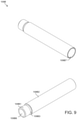
- FIG. 9 is a schematic diagram of first and second views of the screw cover tube of the present teachings.
- FIGS. 10 and 11 are schematic diagrams of first and second configurations of the mount crossbar of the present teachings.
- FIG. 12 is a schematic diagram of first and second views of the baseplate side of the present teachings.
- FIG. 12A is a schematic diagram of first and second views of the z-axis stop bearing of the present teachings
- FIG. 13 is a schematic diagram of first and second views of the microscope plate adapter of the present teachings.
- FIGS. 14A and 14B are schematic diagram of various views of the y-axis block of the present teachings.
- FIG. 14C is a schematic diagram of the y-axis linear bearing of the present teachings.
- FIG. 15A is a schematic diagram of first and second views of the moving assembly of the present teachings.
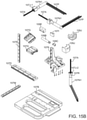
- FIG. 15B is a schematic diagram of an exploded view of the moving assembly of the present teachings.
- FIG. 16 is a schematic diagram of first and second views of the x-axis baseplate of the present teachings
- FIG. 16A is a schematic diagram of first and second views of the block z-axis stop bearing of the present teachings
- FIG. 17 is a schematic diagram of first and second views of the x-axis block of the present teachings.
- FIG. 18A is a schematic diagram of first and second views of the first rail of the present teachings.
- FIG. 18B is a schematic diagram of first and second views of the second rail of the present teachings.
- FIG. 18C is a schematic diagram of first and second views of the third rail of the present teachings.
- FIG. 19 is a schematic diagram of first and second views of the x-axis stop of the present teachings.
- FIG. 20 is a schematic diagram of first and second views of the motor junction box of the present teachings.
- FIG. 21A is a schematic diagram of first and second views of the x-axis linear bearing of the present teachings
- FIG. 21B is a schematic diagram of first and second views of the bumper of the present teachings.
- FIG. 22A is a schematic diagram of first and second views of the gearmotor/ballscrew first configuration of the present teachings
- FIG. 22B is a schematic diagram of an exploded view of the gearmotor/ballscrew first configuration of the present teachings
- FIG. 23A is a schematic diagram of first and second views of the gearmotor/ballscrew second configuration of the present teachings
- FIG. 23B is a schematic diagram of first and second views of the spindle adapter first configuration of the present teachings
- FIG. 23C is a schematic diagram of first and second views of the spindle adapter second configuration of the present teachings.
- FIG. 24A is a schematic diagram of the gearmotor/ballscrew third configuration of the present teachings.
- FIG. 23B is a schematic diagram of first and second views of the spindle adapter third configuration of the present teachings.
- FIG. 24C is a schematic diagram of first and second views of the spindle adapter third configuration of the present teachings.
- FIGS. 25A and 25C are schematic diagrams of various views of the delivery system of the present teachings.
- FIG. 25B is a schematic diagram of an exploded view of the delivery system of the present teachings.
- FIG. 25C-1 is a schematic diagram of the delivery system second configuration of the present teachings.
- FIG. 25C-1A is a schematic diagram of first and second views of the plunger fit of the present teachings.
- FIG. 25C-2 is a schematic diagram of an exploded view of the delivery system second configuration of the present teachings.
- FIG. 25D is a schematic diagram of the delivery system third configuration of the present teachings.
- FIG. 25E is a schematic diagram of an exploded view of the delivery system third configuration of the present teachings.
- FIG. 25F is a schematic diagram of the delivery system fourth configuration of the present teachings.
- FIGS. 25F-1A and 25F-1B are schematic diagrams of first and second views of the plunger extension adapter of the present teachings
- FIG. 25F-2 is a schematic diagram of first and second views of the syringe swing clamp of the present teachings
- FIG. 25F-3 is a schematic diagram of first and second views of the bumper of the present teachings.
- FIG. 25G is a schematic diagram of the delivery system fourth configuration of the present teachings.
- FIG. 26 is a schematic diagram of the syringe system of the present teachings.
- FIG. 26A is a schematic diagram of first and second views of the barrel second configuration of the present teachings.
- FIG. 26B is a schematic diagram of first and second views of the barrel third configuration of the present teachings.
- FIG. 26C is a schematic diagram of first and second views of the syringe second configuration of the present teachings.
- FIGS. 26D and 26E are schematic diagrams of various views of the syringe third configuration of the present teachings.
- FIGS. 26F-26J are schematic diagrams of the syringe filler of the present teachings.
- FIG. 26K is a schematic diagram of a second configuration syringe filler of the present teachings.
- FIG. 27A is a schematic diagram of first and second views of the switch housing of the present teachings.
- FIG. 27B is a schematic diagram of first and second views of the switch housing cap of the present teachings.
- FIG. 28 is a schematic diagram of first and second views of the switch of the present teachings.
- FIG. 29 is a schematic diagram of first and second views of the gearbox of the present teachings.
- FIG. 30 is a schematic diagram of first and second views of the motor nut adapter of the present teachings.
- FIGS. 31A and 31B are schematic diagrams of various views of the barrel slide clip of the present teachings.
- FIG. 32 is a schematic diagram of first and second views of the plunger drive of the present teachings.
- FIG. 33 is a schematic diagram of first and second views of the delivery system connector of the present teachings.
- FIG. 33A is a schematic diagram of first and second views of the delivery system connector second configuration of the present teachings.
- FIG. 34 is a schematic diagram of first and second views of the needle guide of the present teachings.
- FIG. 35 is a schematic diagram of first and second views of the barrel holder of the present teachings.
- FIGS. 35A and 35B are schematic diagrams of various views of the barrel holder second configuration of the present teachings.
- FIG. 36A is a schematic diagram of first and second views of the linear actuator of the present teachings.
- FIG. 36B is a schematic diagram of another view of the linear actuator, and first and second views of the linear bearing of the present teachings;
- FIGS. 37A and 37B are schematic diagrams of various views of the printer third configuration of the present teachings.
- FIG. 37C is a schematic diagram of first and second views of the junction box combination of the present teachings.
- FIG. 37D is a schematic diagram of first and second views of the junction box lower assembly of the present teachings.
- FIG. 37E is a schematic diagram of first and second views of the junction box lower faceplate of the present teachings.
- FIG. 38 is a schematic diagram of the gas spring of the present teachings.
- FIG. 38A is a schematic block diagram of the exemplary printing device of the present teaching.
- FIG. 38B is a schematic block diagram of the exemplary printing device with printing cartridge and vessel wherein printing is performed;
- FIG. 38C is a front top right-side perspective view of the exemplary printing device with a single cartridge delivery system
- FIG. 38D is a front top right-side perspective view of the exemplary printing device with a dual cartridge delivery system
- FIG. 38E is a front top right-side perspective view of a chassis belonging to the exemplary printing device.
- FIG. 38F is a bottom rear left-side perspective view of a chassis belonging to the exemplary printing device.
- FIG. 38G is a front top right-side perspective view of the chassis of the exemplary printing device along with components wherein printing is performed;
- FIG. 38H is a front top right-side exploded view of the chassis of exemplary printing device along with components wherein printing is performed;
- FIG. 38I is a front bottom right-side perspective view of primary carriage belonging to exemplary printer of the present teachings.
- FIG. 38J is a rear top left-side perspective view of primary carriage belonging to exemplary printer of the present teachings.
- FIG. 38K is a front top right-side exploded view of primary carriage belonging to exemplary printer of the present teachings.
- FIG. 38L is a front top right-side exploded view depicting engagement of primary carriage and first sub-carriage of the exemplary printer
- FIG. 38M is a front top right-side partially-exploded view depicting engagement of primary carriage, first sub-carriage and second sub-carriage of the exemplary printer;
- FIG. 38N is a front top right-side perspective view depicting assembly of primary carriage, first sub-carriage and second sub-carriage of the exemplary printer;
- FIG. 38O depicts a front top right-side partially exploded view depicting engagement of primary carriage, first and second sub-carriages and chassis upright of the exemplary printer;
- FIG. 38P depicts a rear bottom left-side partially exploded view depicting engagement of primary carriage, first and second sub-carriages and chassis upright of the exemplary printer;
- FIG. 38Q depicts a front top right-side perspective view depicting engagement of primary carriage, first and second sub-carriages and chassis upright of the exemplary printer;
- FIG. 38R depicts a rear perspective view depicting engagement of primary carriage, first and second sub-carriages and chassis upright of the exemplary printer
- FIG. 38S is a front top right side partially assembled view depicting engagement of a single cartridge delivery system with the remainder of exemplary printer;
- FIG. 38T is a rear top left side perspective view depicting engagement of a single cartridge delivery system with the remainder of printing device;
- FIG. 38U is a front top right side perspective view depicting engagement of a single cartridge delivery system with the remainder of exemplary printing device;
- FIG. 38V is a front top right side partially assembled view depicting engagement of a dual cartridge delivery system with the remainder of exemplary printing device;
- FIG. 38W is a rear top left side perspective view depicting engagement of a dual cartridge delivery system with the remainder of exemplary printing device
- FIG. 38X is a front top right side perspective view depicting assembly comprising a dual cartridge delivery system with remainder of exemplary printing device;
- FIGS. 38Y and 38Z are perspective views of an exemplary single cartridge delivery system
- FIG. 38AA is an exploded view of an exemplary single cartridge delivery system
- FIGS. 38BB and 38CC are perspective views of an exemplary dual cartridge delivery system
- FIG. 38DD is an exploded view of an exemplary dual cartridge delivery system
- FIG. 38EE is perspective view of an exemplary mixing valve and valve mount
- FIG. 38FF is a partially exploded view depicting engagement of exemplary mixing valve and valve mount
- FIG. 38GG is a cross section view depicting engagement of exemplary mixing valve and valve mount
- FIG. 39 is a schematic block diagram of the architecture of the control system of the present teachings.
- FIG. 39A is a flowchart of a first configuration of the method for interpreting G-code of the present teachings
- FIG. 39B is a flowchart of a second configuration of the method for interpreting G-code of the present teachings.
- FIGS. 39C-39I are screen displays of an exemplary configuration the command interface of the present teachings.
- FIGS. 40A and 40B are schematic block diagrams of exemplary configurations of the control system of the present teachings.
- FIG. 41 is a schematic block diagram of the architecture of the motion controller of the present teachings.
- FIGS. 42 -A and 42 -B are schematic block diagrams of exemplary configurations of the architecture of the motion controller of the present teachings
- FIGS. 43, 44A, and 44B are schematic block diagrams of the node configuration system of the present teachings.
- FIGS. 44C and 44D are schematic block diagrams of the sensor configuration system of the present teachings.
- FIG. 45 is a flowchart of the method of the motion controller of the present teachings.
- FIG. 46 is a schematic diagram of the bioprinting system of the present teachings.
- FIG. 47 is a schematic diagram of the target tissue enclosure of the bioprinting system of FIG. 46 ;
- FIG. 48 is a schematic diagram of the robot tool of the present teachings.
- FIGS. 49A and 49B are schematic block diagrams of the control system for the bioprinting system of FIG. 46 ;
- FIG. 50 is a pictorial diagram of the coordinate point conversion of the present teachings.
- FIG. 51 is a pictorial representation of the side views of the first configuration of print nozzles of the present teachings
- FIG. 52 is a pictorial representation of the front and rear views of the first configuration of print nozzles of the present teachings
- FIG. 53 is a pictorial representation of the first configuration of print nozzles of the present teachings.
- FIG. 54 is a pictorial representation of the tool tip sensor of the present teachings.
- FIG. 55 is a pictorial representation of the tool tip sensor configuration of the present teachings.
- FIG. 56 is a pictorial representation of the tool tip and sensors of the tissue enclosure of the present teachings.
- FIG. 57 is a pictorial representation of another configuration of the tool tip and sensors of the tissue enclosure of the present teachings.
- FIG. 58 is a pictorial representation of the third configuration of the tool tip and sensors of the tissue enclosure of the present teachings.
- FIG. 59 is a perspective schematic view of the tool touch-off configuration of the tissue enclosure of the present teachings.
- FIGS. 60-62 are pictorial representations the process of compliant tool calibration of the tissue enclosure of the present teachings
- FIG. 63 is a pictorial representation of the spreader of the present teachings.
- FIG. 64 is a pictorial representation of the spreaders of the present teachings mounted with respect to the tissue enclosure of the present teachings;
- FIG. 65 is a pictorial representation of the spreader and magnetic valve of the present teachings.
- FIG. 66 is a pictorial representation of the spreader and magnetic valve of the present teachings mounted with respect to the tissue enclosure and tool of the present teachings;
- FIG. 67 is a pictorial representation of the magnetic valve of the present teachings.
- FIG. 68 is a pictorial representation of the magnetic field sensed by the spreader and magnetic valve of the present teachings.
- Printing biological material and supporting structures can include (a) simultaneously printing of material (b) precise printing of material and (c) printing particular elements, for example, but not limited to, bio-ink.
- Methods to print biological material can include printing layers of cells, for example, in a holding container, shaping the tissue by etching fine details using, for example, but not limited to, laser and/or water jet.
- a mesh structure can underlie the etched tissue, and the method can include lifting the mesh and etched tissue into a tissue enclosure.
- structure maintenance material 509 FIG. 56
- structure maintenance FIG. 56
- FIG. 56 can be printed into the holding container
- structure maintenance FIG. 56
- gel can be automatically dispensed through an appropriately-sized extrusion device.
- a printing method can include printing the biological material and supporting structures onto a drum-like structure, unrolling the drum-like structure and biological material into growth media, and optionally vibrating the drum-like structure to release the biological material and supporting structures from the drum-like structure.
- the method can optionally include scraping the drum-like structure to release the biological material and supporting structures with, for example, but not limited to, a wire.
- the method can include printing a layer of structure maintenance material 509 ( FIG. 56 ) onto the drum-like structure, printing a layer of biological material onto the drum-like structure, and scraping a layer of printed material from the drum-like structure.
- the method can include loading a holding container with fluid, printing a layer of cells on the fluid, dipping the tissue into the layer of cells, and extracting the layer of cells that adhere to the tissue. In some configurations, the method can include loading the holding container with tissue, and lowering the layer of cells onto the tissue in the holding container where the layer of cells can adhere to the tissue in the holding container.
- Precisely printing biological material can include providing laminar streams of different bio-inks under conditions that inhibit mixing of the bio-inks. For example, a number of reasonably sized tubes can be placed in a nozzle that will be used to provide bio-ink to a printing device. The tubes can maintain laminar flow in the streams. The size of the tubes can be continually reduced so that a small nozzle at the termination of the printing device includes all the different bio-inks.
- bio-inks can include, for example, if optical sensing technology is being used, choosing materials that include indices of refraction that differ from the background in which the bio-ink is printed. In some configurations, air or any kind of gas can be appropriate, and multiple different types of gases can be printed to accommodate variations in fluorescence. Quantum dots and nanoparticle/fluorescent beads can be printed as probes/markers. Entire additional structures that may support tissue generation may be printed along with cells that can ultimately grow into tissue, or that can accompany tissue to, for example, monitor and/or sustain the tissue. The additional structures can be placed in a tissue enclosure after being printed, for example, but not limited to, outside a tissue enclosure.
- the additional structures can include, but are not limited to including, photodetectors, silicon or other semi-conductors, electronics, and sensors that can be collocated with tissue. Feedback on growth and topology of the tissue can be accommodated by, for example, printing and/or placing grid patterns/optical gratings in the vicinity of the inside and/or outside of the tissue and monitoring the contours of the tissue. Marker patterns can be placed around the tissue by depositing ink into media or by cutting out bits of gel. In some configurations, photodetectors can be placed in the gel and can be powered by connecting leads and/or inductive coupling that can power the photodetectors without leads.
- a configuration of the printer and control system of the present teachings is discussed in detail herein in relation to an inverted microscope. However, various types of microscopes may be used.
- the printer of the present teachings can be controlled by the controller of the present teachings to print cells in, for example, a gel-like material.
- references to fasteners can include any type of fastening mechanism including, but not limited to, glue, bolts, screws, nails, and hook-and-eye devices.
- printer 100 of the present teachings can print a multi-dimensional article made of at least one first material.
- Printer 100 can print the multi-dimensional article by using at least one delivery system 103 that can deposit the at least one first type of material(s) into at least one second material(s) resting in at least one tissue enclosure 101 .
- Information about the multi-dimensional article can be gathered during the printing process from a microscope (not shown) having optical access to tissue enclosure 101 through microscope top plate 111 .
- the at least one second material can reach a pre-selected depth in at least one tissue enclosure 101 , the pre-selected depth accommodating a size, shape, and depth of the multi-dimensional article.
- At least one tissue enclosure 101 can be positioned to accommodate at least one vision system 63 ( FIG. 39 ). At least one vision system 63 ( FIG. 39 ) can be, for example, but not limited to, mounted alongside of at least one tissue enclosure 101 . At least one vision system 63 ( FIG. 39 ) can, for example, but not limited to, track the position of at least one needle 103 H ( FIG. 1C ).
- printer 100 can include, but is not limited to including, at least one delivery system 103 , y-axis block 105 , x-axis block 107 , and z-axis baseplate 109 , all resting upon microscope top plate 111 .
- Delivery system 103 can be moved according to at least one motion command 73 ( FIG. 39 ) sent to components described herein with respect to x-axis block 107 .
- Moving delivery system 103 can move needle 103 H to a position within a second material resting in tissue enclosure 101 .
- Delivery system 103 can also be directed according to at least one pump command 81 ( FIG. 39 ) to deposit at least one first material 79 ( FIG. 39 ) at the position.
- a manifold (not shown) can connect a plurality of barrels 103 G ( FIG. 25B ) to a single output port (and single needle 103 H).
- a plurality of delivery systems 103 can be mounted, for example, side-by-side and can print cooperatively and/or asynchronously.
- tissue enclosure 101 can include, but is not limited to including, dish cavity 101 H, dish sides 101 C, dish first support 101 D, dish second support 101 E, and dish third support 101 F.
- Dish cavity 101 H can be formed of, for example, four sides 101 C, joined with, for example, filet edges 1011 A that can enable aligned placement of first configuration dish lid 101 J ( FIG. 2A-1 ) with lid edges 101 K ( FIG. 2A-1 ).
- Dish sides 101 C can include dish divots 101 B that can enable venting of tissue enclosure 101 when first configuration dish lid 101 J ( FIG. 2A-1 ) is in place.
- First configuration dish lid 101 J ( FIG. 2A-1 ) can include floor 101 L ( FIG.
- Second configuration dish lid 101 J- 1 ( FIG. 2A-2 ) can include stacking sides 101 J- 1 A ( FIG. 2A-2 ) and stacking floor 101 J- 1 B ( FIG. 2A-2 ) that can enable stacking of multiple of petri dishes 101 .
- Second configuration dish lid 101 J- 1 ( FIG. 2A-2 ) can include standoffs 101 J- 1 D ( FIG. 2A-2 ) that can, in conjunction with thin rim 101 J- 1 F ( FIG. 2A-2 ), channel condensate from dish adjacent surface 101 J- 1 E ( FIG. 2A-2 ) to outside of tissue enclosure 101 , can prevent contamination of the contents of tissue enclosure 101 by condensate.
- Dish sides 101 C can be any height and width, and can, in some configurations, be flat to accommodate viewing of the contents of petri dish 101 through dish sides 101 C.
- Dish first support 101 D, dish second support 101 E, and dish third support 101 F can, for example, provide resting feet on dish bottom 101 G that can support tissue enclosure 101 .
- the locations of dish first support 101 D, dish second support 101 E, and dish third support 101 F can form a kinematic mount that can enable removal of tissue enclosure 101 at a first orientation and replacement of tissue enclosure 101 at the same first orientation. Any configuration of supports can be used to form the kinematic mount.
- petri dish mounting plate 102 can include, but is not limited to including, plate first rest 102 C 1 , plate second rest 102 C 2 , and dish third rest 102 C 3 .
- Dish first support 101 D can rest on platform 102 G 1 between alignment features 102 C 1 A and 102 C 1 B of plate first rest 102 C 1 .
- Dish second support 101 E can rest on platform 102 G 2 between the alignment features of plate second rest 102 C 2
- dish third support 101 F can rest on platform 102 G 3 between the alignment features of plate third rest 102 C 3 .
- Petri dish mounting plate 102 can be any size and shape, and plate thickness 102 D can be, for example, based on how much side viewing through petri dish side 101 C ( FIG. 2A ) can be accommodated in a particular configuration.
- kinematic plate 102 H and mounting plate second side 102 B can be attached through fasteners accommodated by fastening cavities 102 F 1 / 102 F 2 to microscope plate adapter 109 H ( FIG. 13 ).
- alignment divot 102 E can be use to insure proper placement of petri dish mounting plate 102 .
- standoffs (not shown) can be used to lift petri disk mounting plate 102 to accommodate various microscope configurations.
- microscope top plate 111 can include, but is not limited to including, microscope top plate first side 111 B, microscope top plate second side 111 C, and microscope top plate dish cavity 111 A.
- Microscope top plate 111 can be any shape and size, and can be constructed of any material having characteristics such as, but not limited to, rigidity.
- Dish cavity 111 A can be any shape, size, and depth.
- dish cavity 111 A can be sized according to the size of tissue enclosure 101 , for example, larger than tissue enclosure 101 .
- dish cavity 111 A can be sized according to the size of the viewing means (not shown) of the microscope (not shown) mounted in conjunction with microscope top plate 111 .
- Cavity edges 111 D can be any shape, size, and depth, and can accommodate the mounting of tissue enclosure 101 within cavity edges 111 D, and/or can accommodate the viewing means (not shown) within cavity edges 111 D.
- microscope top plate first side 111 B can be mounted adjacent to microscope plate adapter second side 109 H 2 ( FIG. 4A ).
- microscope top plate second side 111 C can be mounted adjacent to a microscope (not shown).
- z-axis baseplate first configuration 109 ( FIG. 1C ) can be configured in several ways.
- z-axis baseplate first configuration 109 -C 1 can include, but is not limited to including, support rails 109 A-C 1 , screw cover tube 109 B, screw/tube guide 109 J, ball nut 109 C, carriage 109 D, and optical encoder 109 E.
- Z-axis baseplate first configuration 109 -C 1 can also include baseplate side 109 F, mount crossbar 109 G, and microscope plate adapter first side 109 H 1 .
- Screw cover tube 109 B can accommodate lead/ball screw 107 A ( FIG. 15A ), and can be held in place by screw/tube guide 109 J.
- Ball nut 109 C can form, along with lead/ball screw 107 A ( FIG. 15A ), a lead/ball screw configuration to enable linear motion of a print head.
- Z-axis baseplate first configuration 109 -C 1 can be mounted flush with microscope top plate first side 111 B ( FIG. 3 ).
- support rails first configuration 109 A-C 1 can include, but are not limited to including, cavities 109 A 1 and divot 109 A 2 to accommodate the structure of z-axis baseplate 109 -C 1 .
- Cavities 109 A 1 can be sized and shaped to maintain strength and stability in printer 100 ( FIG. 2A ) while reducing the weight of printer 100 ( FIG. 2A ), and can accommodate cable runs.
- Support rails first configuration 109 A-C 1 can be tapered 109 A 3 between rail first end 109 A 4 and rail second end 109 A 5 , where rail first end 109 A 4 and rail second end 109 A 5 can be different sizes relative to each other.
- Support rails first configuration 109 A-C 1 can be tapered to, for example, but not limited to, provide viewing access to tissue enclosure 101 ( FIG. 2A ).
- Support rails first configuration 109 A-C 1 can be any shape, size, and depth depending on weight requirements of printer 100 ( FIG. 2A ), viewing requirements, if any, of the contents of tissue enclosure 101 ( FIG. 2A ), and fastening requirements of z-axis baseplate first configuration 109 -C 1 ( FIG. 4A ).
- Support rails first configuration 109 A-C 1 can include fastening cavities 109 A 6 which can be any shape, size, and depth, and can occur in any quantity sufficient to maintain the structural integrity of printer 100 ( FIG. 2A ), and to insure that printer 100 ( FIG.
- each of support rails first configuration 109 A-C 1 can include six fastening cavities 109 A 6 that can mate support rails 109 A to baseplate side 109 F ( FIG. 4A ) and mount crossbar 109 G ( FIG. 4A ), for example.
- Support rails first configuration 109 A-C 1 can also include fastening bores 109 A 7 to accommodate fastening support rails first configuration 109 A-C 1 to microscope plate adapter 109 H ( FIG. 13 ), for example.
- z-axis baseplate second configuration 109 -C 2 can include, but is not limited to including, support rails 109 A-C 2 , screw cover tube 109 B, ball nut 109 C, carriage 109 D, and optical encoder 109 E.
- Z-axis baseplate second configuration 109 -C 2 can also include baseplate side 109 F, mount crossbar 109 G, and microscope plate adapter first side 109 H 1 ( FIG. 4A ).
- Z-axis baseplate second configuration 109 -C 2 can be mounted flush with microscope top plate first side 111 B ( FIG. 3 ).
- Optical encoder 109 E can track the motion of lead/ball screw 107 A ( FIG. 15A ) and provide that information to processor 55 ( FIG.
- Optical encoder 109 E can be wired or wireless, and can include, for example, but not limited to, an absolute or incremental encoder. In some configurations, a RENISHAW® L-9517-9524-03-B optical encoder can be used.
- support rails second configuration 109 A-C 2 can include, but are not limited to including, cavities 109 A 1 - 1 , 109 A 1 - 2 , and divot 109 A 2 to accommodate the structure of z-axis baseplate 109 -C 2 .
- Cavities 109 A 1 and 109 A 1 - 2 can be sized and shaped to maintain strength and stability in printer 100 ( FIG. 2A ) while reducing the weight of printer 100 ( FIG. 2A ), and can accommodate cable runs.
- Support rails second configuration 109 A-C 2 can be tapered 109 A 3 between rail first end 109 A 4 and rail second end 109 A 5 , where rail first end 109 A 4 and rail second end 109 A 5 can be different sizes relative to each other.
- Support rails second configuration 109 A-C 2 can be tapered to, for example, but not limited to, provide viewing access to tissue enclosure 101 ( FIG. 2A ).
- Support rails second configuration 109 A-C 2 can be any shape, size, and depth depending on weight requirements of printer 100 ( FIG. 2A ), viewing requirements, if any, of the contents of tissue enclosure 101 ( FIG. 2A ), and fastening requirements of z-axis baseplate 109 -C 2 ( FIG. 5A ).
- Support rails second configuration 109 A-C 2 can include fastening cavities 109 A 6 which can be any shape, size, and depth, and can occur in any quantity sufficient to maintain the structural integrity of printer 100 ( FIG. 2A ), and to insure that printer 100 ( FIG. 2A ) has positional stability.
- each of support rails second configuration 109 A-C 2 can include six fastening cavities 109 A 6 that can mate support rails second configuration 109 A to baseplate side 109 F ( FIG. 5A ) and mount crossbar 109 G ( FIG. 5A ), for example.
- Support rails second configuration 109 A-C 2 can also include fastening bores 109 A 7 to accommodate fastening support rails second configuration 109 A-C 2 to microscope plate adapter 109 H ( FIG. 13 ), for example.
- z-axis baseplate third configuration 109 -C 3 can include, but is not limited to including, support rails third configuration 109 A-C 3 , screw cover tube 109 B, ball nut 109 C, carriage 109 D, and optical encoder 109 E.
- Z-axis baseplate third configuration 109 -C 3 can also include baseplate side 109 F, mount crossbar 109 G, and microscope plate adapter first side 109 H 1 .
- Z-axis baseplate third configuration 109 -C 3 can be mounted flush with microscope top plate first side 111 B ( FIG. 3 ).
- support rails third configuration 109 A-C 3 can include, but are not limited to including, single cavity 109 A 1 ( FIG. 6A ) and divot 109 A 2 , and/or or solid face 109 P, or a combination of cavities and solid faces.
- Support rails third configuration 109 A-C 3 can be tapered 109 A 3 between rail first end 109 A 4 and rail second end 109 A 5 , where rail first end 109 A 4 and rail second end 109 A 5 can be different sizes relative to each other.
- Support rails third configuration 109 A-C 3 can be tapered to, for example, but not limited to, provide viewing access to tissue enclosure 101 ( FIG. 2A ).
- Support rails third configuration 109 A-C 3 can be any shape, size, and depth depending on weight requirements of printer 100 ( FIG. 2A ), viewing requirements, if any, of the contents of tissue enclosure 101 ( FIG. 2A ), and fastening requirements of z-axis baseplate third configuration 109 -C 3 ( FIG. 6A ).
- Support rails third configuration 109 A-C 3 can include fastening cavities 109 A 6 which can be any shape, size, and depth, and can occur in any quantity sufficient to maintain the structural integrity of printer 100 ( FIG. 2A ), and to insure that printer 100 ( FIG. 2A ) has positional stability.
- each of support rails third configuration 109 A-C 3 can include six fastening cavities 109 A 6 that can mate support rails 109 A to baseplate side 109 F ( FIG. 6A ) and mount crossbar 109 G ( FIG. 6A ), for example.
- Support rails third configuration 109 A-C 3 can also include fastening bores 109 A 7 to accommodate fastening support rails third configuration 109 A-C 3 to microscope plate adapter 109 H ( FIG. 13 ), for example.
- screw/tube guide 109 J can include, but is not limited to including, tube cavity 109 J 1 , fastener cavity 109 J 2 , and shaped structure 109 J 3 .
- Screw/tube guide 109 J can optionally include at least one bearing (not shown) within tube cavity 109 J 1 , for example, along tube cavity wall 109 J 4 , for grasping tube 109 B ( FIG. 6A ).
- Shaped structure 109 J 3 can be molded to conform with baseplate side 109 F ( FIG. 6A ), and can be fastened to baseplate side 109 F ( FIG. 6A ) through fastener cavity 109 J 2 , which can be any size and shape to accommodate any type of fastener.
- ball nut 109 C can include, but is not limited to including, first ball nut cavity 109 C 2 , ball nut threads 109 C 1 , ball nut body 109 C 3 , ball nut end taper 109 C 4 , ball nut end 109 C 5 , and second ball nut cavity 109 C 6 .
- First ball nut cavity 109 C 2 and second ball nut cavity 109 C 6 can form a single hollow core accommodating ballscrew 107 A ( FIG. 15 ).
- ball nut 109 C can include, for example, five ball nut threads 109 C 1 , although any number and size of threads can be used.
- Ball nut 109 C can be installed into baseplate side 109 F ( FIG.
- Ball nut body 109 C 3 can be any size and thickness, and can be constructed of any material with characteristics including, but not limited to, rigidity and durability.
- Ball nut 109 C can include ball nut chamfer 109 C 4 to ball nut end 109 C 5 .
- Ball nut taper 109 C 4 can be any angle, and ball nut end 109 C 5 can be any size, forming the thickness of ball nut walls 109 C 3 .
- screw cover tube 109 B can include, but is not limited to including, tube end cap 109 B 1 and tube body 109 B 2 .
- tube body 109 B 2 can include tube body cavity 109 B 7 that can, together with end cap cavity 109 B 6 , form a continuous opening for lead/ball screw 107 A ( FIG. 15A ).
- Tube body 109 B 2 can be joined to tube end cap 109 B 1 at thread relief face 109 B 3 which can be, but is not limited to being, recessed relative to both tube body 109 B 2 and tube end cap 109 B 1 .
- tube end cap 109 B 1 can enable snap-on installation of tube body 109 B 2 .
- mount crossbars 109 G and 109 G-A can include, but are not limited to including, crossbar cavities 109 G 4 , end fastener cavities 109 G 2 , and side fastener cavities 109 G 3 .
- mount crossbar 109 G can be shaped to support and be fastened to, through end fastener cavities 109 G 2 , rails 109 A-C 1 /C 2 /C 3 ( FIGS. 4B / 5 B/ 6 B).
- Mount crossbar 109 G can be any height and length, depending on the distance between rails 109 A-C 1 /C 2 /C 3 ( FIGS.
- mount crossbar 109 G can be chosen based on factors such as material used to construct mount crossbar 109 G and stability requirements.
- Side fastener cavities 109 G 3 can accommodate fasteners that can be used to attach mount crossbar 109 G to microscope plate adapter first side 109 H 1 ( FIG. 4A ).
- Crossbar cavities 109 G 4 can be any size and shape, and can be completely absent in some configurations. When present, crossbar cavities 109 G 4 can enable weight reduction and provide cable runs. Crossbar 109 G-A can include recess 109 G 5 that can accommodate other features of printer 100 .
- baseplate side 109 F can provide rail runs that can interconnect z-axis baseplate 109 ( FIG. 1C ) with x-axis block 107 K ( FIG. 17 ).
- Baseplate side 109 F can include, but is not limited to including, first rail run 109 F 5 that can enable mounting of first rail 107 M ( FIG. 18A ), that can interconnect with second rail indent 107 B 7 ( FIG. 16 ).
- Baseplate side 109 F can include second rail run 109 F 6 that can enable mounting of second rail 107 E ( FIG. 18B ) that can interconnect with second rail indent 107 B 9 ( FIG. 16 ).
- Baseplate side 109 F can include baseplate ribs 109 F 1 , screw run indent 109 F 2 , fastener cavities 109 F 3 , and structural indents 109 F 4 .
- Baseplate ribs 109 F 1 can be any shape, size, and depth, and can provide stiffening, while allowing for reduced (with respect to a non-ribbed structure) weight, to baseplate side 109 F.
- baseplate ribs 109 F 1 may not be present, and instead baseplate side 109 F can include a solid plate in the place of baseplate ribs 109 F 1 .
- solid plates can be interleaved among baseplate ribs 109 F 1 .
- Screw run indent 109 F 2 can be any shape and size, and can accommodate ballscrew 107 A ( FIG. 15 ).
- Structural indents 109 F 4 can accommodate functional features of printer 100 ( FIG. 2A ) and/or can enable weight reduction.
- Baseplate side 109 F can be constructed of any material and can be any size, shape, and depth. In some embodiments, baseplate side 109 F can include characteristics that can enable stability as printer 100 ( FIG. 2A ) operates.
- Z-axis stop bearing 107 F 7 - 1 can be mounted at stop bearing mounting point 109 F 7 .
- Z-axis stop bearing 107 F 7 - 1 can include, but is not limited to including, mount point 107 F 7 - 1 A for screw cover tube 109 B ( FIG. 9 ), fastening cavity 107 F 7 - 1 B to fasten z-axis stop bearing 107 F 7 - 1 to z-axis baseplate 109 F ( FIG. 12 ), and contoured features such as, for example, but not limited to, edge filet 107 F 7 - 1 C to streamline printer 100 ( FIG. 1A ).
- microscope plate adapter 109 H can include, but is not limited to including, plate adapter first side 109 H 1 , plate adapter second side 109 H 2 , and plate adapter dish cavity 109 H 3 .
- Microscope plate adapter 109 H can also include at least one fastening cavity 109 H 4 and 109 H 5 ( FIG. 5A ).
- Fastening cavities 109 H 4 and 109 H 5 can be used for any purpose such as, for example, but not limited to, cable runs.
- rails 109 A-C 1 /C 2 /C 3 FIGS.
- mount crossbar FIG. 10
- baseplate side 109 F FIG. 12
- microscope top plate FIG. 3
- microscope top plate FIG. 3
- y-axis block 105 can direct movement of delivery system 103 ( FIG. 1C ).
- Y-axis block 105 can be coupled with delivery system 103 ( FIG. 1C ) along y-block base 105 G with, for example, but not limited to, fasteners compatible with fastener cavities 105 P.
- Y-axis block 105 can be coupled with delivery system 103 ( FIG. 1C ) in any way including, but not limited to, using screws, bolts, nails, and hook-eye fasteners.
- Y-axis guide rails 105 Q for y-axis guides 105 D can enable movement of y-axis block 105 .
- Y-axis guides 105 D can be attached to y-axis guide rails 105 Q by fasteners compatible with fastener cavities 105 F.
- Y-axis guides 105 D can include guide slots 105 E that can be sized to accommodate, for example, first rail 107 M ( FIG. 18A ).
- Y-axis guides 105 D and guide slots 105 E can be any size, shape, and depth.
- Y-axis block 105 can include, but is not limited to including, y-block support 105 A, y-block support cavities 105 B/ 105 C, y-block fastener cavities 105 P, and y-block lip 105 M.
- Y-block support 105 A can provide stability to y-axis block 105 , and can include y-block cavity 105 B to adjust the weight of y-axis block 105 .
- Y-block cavities 105 B/ 105 C can be any size and shape, can be completely absent from y-axis block 105 , and can include partial cut-outs in which y-block cavities 105 B/ 105 C extend partly into the depth of solid features of y-axis block 105 .
- Y-block lip 105 M can provide additional stability in the coupling between y-axis block 105 and delivery system 103 ( FIG. 1C ), and can include a datum surface or indexing face by which subsequent assemblies can be aligned and installed.
- Y-block lip 105 M can enable maintenance of orthogonal installation and can constrain the position in which the extruder subassembly can be installed.
- Scale application surface 105 N can provide a mounting position for a linear encode scale.
- Y-axis block 105 can include ball nut holder 105 H 1 and screw tube holder 105 H 2 providing stable mounting for ball nut 109 C ( FIG. 8 ) and screw cover tube 109 B ( FIG. 9 ).
- y-block support 105 A can be tapered from first support end 105 K 1 to second support end 105 K 2 where first support end 105 K 1 can be, but is not limited to being, a different size from second support end 105 K 2 .
- first support end 105 K 1 can be shaped to accommodate dimensional characteristics of x-axis block 107 ( FIG. 15A ).
- Y-block base 105 G can include base indent 105 L that can be any size, shape, and depth. Base indent 105 L can provide weight accommodations for y-axis block 105 .
- Various y-block filets 105 J can optionally provide strength and stability to y-axis block 105 .
- y-axis linear bearing 105 D can ride on second rail 107 E ( FIG. 18B ) that can couple y-axis block ( FIG. 14A ) to x-axis block 107 K ( FIG. 17 ).
- Y-axis linear bearing 105 D can include, but is not limited to including, guide slot 105 E and guide fastener cavity 105 D 1 .
- guide slot 105 E can include first guide rail section 105 E 1 and second guide rail section 105 E 2 that can insure stable performance of the linear guide.
- Mounting face 105 D 2 can be elevated to accommodate various fastener sizes in guide fastener cavity 105 D 1 .
- Mount side 105 D 3 can support elevated of mounting face 105 D 2 .
- indent 105 D 4 can support a limit stop, for example, a compliant limit stop.
- y-axis linear bearing 105 D can include any one of a variety commercially-available linear bearings.
- block assembly 107 can enable movement of delivery system 103 ( FIG. 1C ).
- Block assembly 107 can include motors 107 N and gears 107 R, powered through cabling 107 P, that can power movement of separate ballscrews 107 A in x, y, and z directions as directed by a print head controller 61 .
- Block assembly 107 can include, but is not limited to including, x-axis baseplate 107 B and x-axis stability structure 107 K.
- Block assembly 107 can couple with y-axis block 105 ( FIG. 14A ) through, for example, rail 107 E and rail guides 105 D ( FIG. 14A ) which can provide coupling with delivery system 103 ( FIG. 1C ).
- x-axis baseplate 107 B can provide a mounting and stability platform for various elements of printer 100 ( FIG. 1A ).
- X-axis baseplate 107 B can be mounted, using, for example, mounting fastening indents 107 B 15 and fasteners, onto z-axis baseplate 109 ( FIG. 1C ).
- X-axis baseplate 107 B can be structured to fit within supports such as, for example, support rails 109 A-C 1 ( FIG. 4A ), 109 A-C 2 ( FIG. 5A ), and/or 109 A-C 3 ( FIG. 6A ).
- Features such as, for example, mount 107 B 3 for optical encoder 109 E ( FIG.
- X-axis baseplate 107 B can be lightened and lifted by features such as cavities 107 B 2 and indents 107 B 4 / 107 B 5 / 107 B 6 , and can be streamlined by positioning elements of printer 100 ( FIG.
- X-baseplate first mount 107 B 12 and x-baseplate second mount 107 B 4 can provide a mounting locations for spindle adapters 107 J
- x-baseplate second mount 107 B 11 can provide a mounting location for fastening spot for x-axis stopper 1071
- x-baseplate third mount 107 B 14 can provide a mounting location for stop bearing 107 B 20 ( FIG. 16A ).
- X-axis baseplate 107 B can include indentations that can accommodate ballscrew rails.
- first rail indent 107 B 7 can accommodate first rail 107 M
- second rail indent 107 B 9 can accommodate second rail 107 F
- third rail indent 107 B 13 can accommodate third rail 107 D.
- Stop bearing 107 B 20 ( FIG. 16A ) can be mounted at bearing mount point 107 B 15 .
- Block z-axis stop bearing 107 F 7 - 2 can be mounted at block stop bearing mounting point 107 B 14 .
- Block z-axis stop bearing 107 F 7 - 2 can include, but is not limited to including, mount point 107 F 7 - 2 A for screw cover tube 109 B ( FIG. 9 ), fastening cavity 107 F 7 - 2 B to fasten block z-axis stop bearing 107 F 7 - 2 to x-axis block 107 B ( FIG. 16 ), and contoured features such as, for example, but not limited to, edge filet 107 F 7 - 2 C to streamline printer 100 ( FIG. 1A ).
- x-axis block 107 K can provide support for y-axis block 105 ( FIG. 14A ), and can provide mounting cavities for various elements of printer 100 ( FIG. 1A ).
- X-axis block 107 K can couple with y-axis block 105 ( FIG. 14A ) by mounting fourth rail 107 E in guide slots 105 E ( FIG. 14A ).
- Side tabs 107 K 9 can provide an integrated y-axis hard stop.
- fastener indents 107 K 6 and associated fasteners can be used to couple fourth rail 107 E ( FIG. 16 ) with x-axis block 107 K.
- X-axis block 107 K can couple with x-axis baseplate 107 B ( FIG. 16 ) through rail guide 107 K 11 third rail indent 107 B 13 ( FIG. 16 ) for mounting third rail 107 D ( FIG. 18C ).
- X-block y-axis support 107 K 1 can include filet 107 K 62 to improve strength and stability, and can be tapered to possibly accommodate streamlined printer feature placement.
- X-axis block 107 K can be coupled to linear bearings 107 G ( FIG. 15B ) at carriage indents 107 K 4 and through fastening indents 107 K 8 and associated fasteners. Linear bearings 107 G ( FIG.
- First x-block mounting cavity 107 K 2 and second x-block mounting cavity 107 K 3 - 2 can provide passages for ballscrews 107 A ( FIG. 15B ).
- X-block optical encoder mounting 107 K 3 can provide a mounting location for optical encoder 109 E ( FIG. 11 ), and lip 107 K 3 - 1 can provide an indexing face to aid in optimal alignment/calibration of optical encoder 109 E ( FIG. 11 ).
- Support fins 107 K 7 can provide structural support for mounting flange 107 K 13 that can be coupled to linear bearings 107 G ( FIG. 15B ) and thus third rail 107 D ( FIG. 18C ) through fastener indents 107 K 8 and associated fasteners.
- first rail 107 M can operably couple z-axis baseplate first side run 109 F 5 ( FIG. 12 ) with x-axis baseplate 107 B ( FIG. 16 ) at first rail indent 107 B 7 ( FIG. 16 ).
- First rail 107 M can include first side fastening cavities 107 M 1 on first rail first side 107 M 5 that can penetrate through first rail 107 M to first rail second side 107 M 6 through second side fastening cavities 107 M 7 .
- First rail 107 M can include any number of first side fastening cavities 107 M 1 , for example, but not limited to, six, and can be any length, width, and depth.
- First rail 107 M can also include first rail slot 107 M 3 , second rail slot 107 M 2 , side face 107 M 4 that can enable locking and stable interconnection with z-axis carriages 109 D 1 ( FIGS. 4A / 5 A/ 6 A).
- second rail 107 E can operably couple z-axis baseplate second side run 109 F 6 ( FIG. 12 ) with x-axis baseplate 107 B ( FIG. 16 ) at second rail indent 107 B 9 ( FIG. 16 ).
- Second rail 107 E can include first side fastening cavities 107 E 1 on second rail first side 107 E 5 that can penetrate through second rail 107 E to second rail second side 107 E 6 through second side fastening cavities 107 E 7 .
- Second rail 107 E can include any number of first side fastening cavities 107 E 1 , for example, but not limited to, eight, and can be any length, width, and depth.
- Second rail 107 E can also include second rail slot 107 E 3 , second rail slot 107 E 2 , side face 107 E 4 that can enable locking and stable interconnection with z-axis carriages 109 D ( FIGS. 4A / 5 A/ 6 A).
- third rail 107 D can operably couple x-axis block 107 K ( FIG. 17 ) with x-axis baseplate 107 B ( FIG. 16 ) at third rail indent 107 K 11 (FIG. 17 ).
- Third rail 107 D can include first side fastening cavities 107 D 9 on third rail first side 107 D 5 that can penetrate through third rail 107 D to third rail second side 107 D 6 through second side fastening cavities 107 D 7 .
- Third rail 107 D can include any number of first side fastening cavities 107 D 9 , for example, but not limited to, ten, and can be any length, width, and depth.
- Third rail 107 D can include third rail slot 107 D 3 , third rail slot 107 D 2 , and side face 107 D 4 that can enable locking and stable interconnection with linear bearing 107 G ( FIG. 15B ).
- y-axis stop 1071 can stop the progress of ballscrew 107 A ( FIG. 15A ) and optical encoder 109 E ( FIG. 11 ) by resting in the path of y-axis block 107 K ( FIG. 17 ).
- Y-axis stop 1071 can be mounted at stop mounting 107 B 11 ( FIG. 16 ).
- Y-axis stop 1071 can include, but is not limited to including, fastening cavities 10711 and stop extension 10712 . Fastening cavities 10711 and associated fasteners can couple y-axis stop 1071 with x-axis baseplate 107 B ( FIG. 16 ).
- stop extension 10712 can be sized to accommodate the size of mounting edge 107 K 14 ( FIG. 17 ).
- Y-axis stop 1071 can be constructed any material, and in any size, shape, and depth.
- motor junction box 109 J can surround motors 103 A ( FIG. 25A ).
- motor 103 A FIG. 25A
- motor 103 A FIG. 25A
- Motor 103 A FIG. 25A
- Motor 103 A FIG. 25A
- Motor 103 A FIG. 25A
- Motor junction box 109 J can include any number of wire recesses and wire channels such as, for example, but not limited to, wire channel 109 J 2 .
- Junction box indents 109 J 3 can be used to attach motor junction box 109 J to any fixture. Junction box indents 109 J 3 can proceed through the length of motor junction box 109 J, or can proceed some fraction of the length of motor junction box 109 J. Motor junction box 109 J can be constructed of any material suitable for junction box use such as, for example, but not limited to, plastic and stainless steel.
- x-axis linear bearing 107 G can ride on third rail 107 M ( FIG. 18C ) that can couple x-axis block 107 K ( FIG. 17 ) to x-axis baseplate ( FIG. 16 ).
- X-axis linear bearing 107 G can include, but is not limited to including, guide slot 107 G 3 and guide fastener cavity/indent 107 G 4 .
- guide slot 107 G 3 can include guide rail holder 107 G 2 that can insure stable performance of the linear guide.
- X-axis linear bearing 107 G can optionally include bumper 107 G 1 that can buffer possible impacts when sliding on first rail 107 M ( FIG. 18C ).
- bumper 107 G 1 can include, but is not limited to including, nib 107 G 1 - 1 , mount stopper 107 G 1 - 2 , and mounting peg 107 G 1 - 3 .
- Nib 107 G 1 - 1 can provide impact buffering, and can be constructed of any relatively flexible material.
- Mounting peg 107 G 1 - 3 can securely engage nib 107 G 1 - 1 with x-axis carriage 107 G ( FIG. 21A ), and mount stopper 107 G 1 - 2 can provide a depth of engagement for nib 107 G 1 - 1 .
- optical encoder non-contact limit magnets can buffer travel impacts, as well as hard stops that can be placed on any of the axes.
- gearmotor/ballscrews 107 N can enable linear motion in x, y, and z directions by propelling x-axis block 107 K ( FIG. 17 ), y-axis block 105 ( FIG. 14A ), and z-axis baseplate 109 ( FIG. 1C ).
- Gearmotor/ballscrew 107 N- 1 can include, but is not limited to including, power wires 107 P, motor 107 N, gearbox 107 R, and ballscrew shaft 107 A.
- Motor 107 N can be, but is not limited to being, a 60 W brushless DC servo gearmotor that can be purchased commercially from, for example, but not limited to, Maxon Motor.
- linear motors can be used, for example, but not limited to, linear motors with or without air bearing linear guides.
- the linear motors can be, but are not limited to being any type of magnetic linear motor including, but not limited to, synchronous, induction, and homopolar types.
- Gearbox 107 R can be, but is not limited to being, a 16 mm spindle drive that can be purchased commercially from, for example, but not limited to, Maxon Motor.
- Gearbox 107 R can include, but is not limited to including, a planetary gear.
- Ballscrew shaft 107 A can include screw shaft interface 107 N 3 that can enable coupling with gearbox 107 R through gearbox engagement 107 N 4 .
- Gearbox 107 R can engage with motor 107 N through motor engagement 107 N 5 .
- gearmotor/ballscrews 107 X- 1 can include gearbox 107 R that can be fitted with spindle adapter 107 J- 1 to enable an interface with ball nut 109 C ( FIG. 8 ).
- Spindle adapter 107 J- 1 can include spindle adapter recessed opening 107 J- 16 that can enable flushed mounting of spindle adapter fasteners 107 J- 3 .
- spindle adapter 107 J- 1 can form a closed loop and can be fastened to gearbox 107 R by fasteners 107 J- 3 that can fit into spindle fastener cavities 107 J- 11 and gearbox cavities 107 J- 4 .
- spindle adapter 107 J- 1 can be open-ended which can streamline the profile of printer 100 ( FIG. 1A ).
- spindle adapter first configuration 107 J- 1 can be mounted onto, for example, but not limited to, x-axis baseplate 107 B ( FIG. 16 ) at baseplate first mount 107 B 12 ( FIG. 16 ) using, for example, tapped hole array 107 J- 5 and associated fasteners. Tapped hold array 107 J- 5 can enable screw to be installed through the back of x-axis baseplate 107 B.
- Dowel pin bores 107 J- 15 can accommodate dowel pins that can be used, for example, to achieve a high level of parallelism between the ballscrew and the railways.
- Gearbox interface cavities 107 J- 12 can accept fasteners 107 J- 3 ( FIG.
- Spindle fastener cavities 107 J- 11 can include recessed fastener cavities 107 J- 14 .
- Spindle adapter recessed opening 107 J- 16 can include beveled edges 107 J- 13 to enable, for example, secure coupling.
- spindle adapter second configuration 107 J- 1 - 1 can include an open-ended assembly motor mount.
- Spindle adapter second configuration 107 J- 1 - 1 can be mounted onto, for example, but not limited to, x-axis baseplate 107 B ( FIG. 16 ) at baseplate first mount 107 B 12 ( FIG. 16 ) using, for example, tapped hole array 107 J- 5 and associated fasteners.
- Dowel pin bores 107 J- 15 can accommodate dowel pins that can be used, for example, to achieve a high level of parallelism between the ballscrew and the railways.
- Gearbox interface cavities 107 J- 12 ( FIG. 23B ) can accept fasteners 107 J- 3 ( FIG.
- spindle adapter second configuration 107 J- 1 - 1 with gearbox 107 R ( FIG. 23A ).
- Spindle fastener cavities 107 J- 11 can include recessed fastener cavities 107 J- 14 .
- Spindle adapter recessed opening 107 J- 16 can include beveled edges 107 J- 13 to enable, for example, secure coupling.
- Open end 107 J- 1 - 2 can enable different mounting options from spindle adapter 107 J- 1 ( FIG. 23B ).
- gearmotor/ballscrew third configuration 107 X- 2 can include gearbox 107 R that can be fitted with spindle adapter 107 J- 2 to enable an interface with ball nut 109 C ( FIG. 8 ).
- Spindle adapter 107 J- 2 can include adapter protrusions 107 J- 23 that can provide a slip fit that can aid in the concentric alignment of the motor adapter to the ball nut positioning feature.
- spindle adapter 107 J- 2 can form a closed loop and can be fastened to gearbox 107 R by fasteners 107 J- 31 that can fit into spindle fastener cavities 107 J- 21 and gearbox cavities 107 J- 4 .
- spindle adapter 107 J- 2 can be open-ended which can streamline the profile of printer 100 ( FIG. 1A ).
- spindle adapter third configuration 107 J- 2 can be mounted onto, for example, but not limited to, x-axis block 107 K ( FIG. 16 ) at first x-block mounting cavity 107 K 22 ( FIG. 17 ) using, for example, spindle mounting cavities 107 J- 24 and associated fasteners.
- Gearbox interface cavities 107 J- 22 can accept fasteners 107 J- 31 ( FIG. 24A ), and can enable flush mounting of spindle adapter 107 J- 2 with gearbox 107 R ( FIG. 24A ).
- Spindle fastener cavities 107 J- 21 can include recessed fastener cavities 107 J- 14 .
- spindle adapter fourth configuration 107 J- 2 - 1 can include, for example, but not limited to, open-ended assembly motor mount 107 J- 2 - 1 A.
- Spindle adapter fourth configuration 107 J- 2 - 1 can be mounted onto, for example, but not limited to, x-axis block 107 K ( FIG. 16 ) at first x-block mounting cavity 107 K 22 ( FIG. 17 ) using, for example, spindle mounting cavities 107 J- 22 and associated fasteners.
- Gearbox interface cavities 107 J- 24 can accept fasteners 107 J- 31 ( FIG. 24A ), and can enable flush mounting of spindle adapter 107 J- 2 - 1 with gearbox 107 R ( FIG. 24A ).
- Spindle fastener cavities 107 J- 21 can include recessed fastener cavities 107 J- 14 .
- delivery system 103 can deliver at least one first material to a receptacle holding at least one second material.
- the receptacle can include tissue enclosure 101 ( FIG. 1A ).
- Delivery system 103 can include, but is not limited to including, gear box 103 B and motor 103 A moving delivery system 103 within the at least one second material in tissue enclosure 101 ( FIG. 1A ) to specific positions based on at least one motion command 73 ( FIG. 39 ).
- Syringe barrel 103 G can rest in syringe holder 103 K, which can rest upon needle guide 103 J that can provide a cavity for needle 103 H.
- Syringe system connector 103 E can couple needle guide 103 J and linear actuator 103 L, and can also couple delivery system 103 with mount crossbar 109 G ( FIG. 10 ) and y-axis block 105 ( FIG. 14A ) at y-block base 105 G ( FIG. 14A ).
- Linear actuator 103 L can include at least one actuator linear bearing 103 N ( FIG. 25A ) upon which plunger drive 103 M can be mounted.
- Linear actuator 103 L can be operably coupled with y-axis block at, for example, fastener indents 103 U ( FIG. 25C ) using associated fasteners.
- the geometry of each configuration of delivery system described herein can include geometries that can enable retraction of syringe 103 G 1 ( FIG.
- Motor 103 A can drive linear actuator 103 T ( FIG. 36A ) with the efficiency and speed required of syringe system 103 G 1 ( FIG. 26 ).
- Motor 103 A can be, for example, AC or DC, and can be brushless or not. Motors such as, for example, but not limited to, the MAXON® RE16-118705, can be used in some configurations.
- Gearbox 103 B ( FIG. 29 ) can be operably coupled with motor 103 A at motor end 103 A 2 .
- delivery system second configuration 103 - 1 can include plunger extension 103 - 1 A that can include a knurled head thumb screw with a shoulder, for example.
- Plunger extension 103 - 1 A can include a threaded portion that can operably couple with plunger 103 F.
- Plunger extension 103 - 1 A can also include a head that can rest in the assembly of plunger fit 103 - 1 B ( FIG. 25C-1A ), barrel slide clip 103 D ( FIG. 31A ), and plunger drive first configuration 103 M ( FIG. 32 ), or a sub-assembly including some of the parts.
- plunger fit 103 - 1 B can provide an adaptable and secure seat, for example, for plunger extension 103 - 1 A ( FIG. 25C-1 ). Any type of plunger extension can be accommodated.
- Plunger fit 103 - 1 B can include extension seat 103 - 1 B 2 surrounded by seat stabilizing legs 1031 B 1 .
- Plunger fit 103 - 1 B can operably couple with first configuration plunger drive 103 M ( FIG. 32 ) at drive coupling mount head 103 - 1 B 3 .
- delivery system third configuration 103 - 2 can include plunger extension 103 - 1 A that can include a knurled head thumb screw with a shoulder, for example.
- Plunger extension 103 - 1 A can include a threaded portion that can operably couple with plunger 103 F.
- Plunger extension 103 - 1 A can also include a head that can rest in second configuration plunger drive 103 M- 1 .
- Second configuration plunger driver 103 M- 1 can include, but is not limited to including, at least one cut-out 103 - 2 M that can accommodate various sizes of plunger extension 103 - 1 A.
- Third configuration delivery system 103 - 2 can also include syringe swing clamp ( FIG.
- Syringe swing clamp ( FIG. 25F-2 ) can include pressure-controlled positioning through the assembly of spring mount 103 X and spring 103 Y.
- delivery system fourth configuration 103 - 3 can include plunger extension 103 - 1 A that can include a knurled head thumb screw with a shoulder, for example.
- Plunger extension 103 - 1 A can include a threaded portion that can operably couple with plunger 103 F.
- Plunger extension 103 - 1 A can also include a head that can rest in second configuration plunger drive 103 M- 1 .
- Delivery system fourth configuration 103 - 3 can include syringe swing clamp ( FIG. 25F-2 ) that can, coupled with bumper 103 W ( FIG. 25F-3 ), retain the position of syringe 103 FF ( FIG.
- Syringe swing clamp 103 T ( FIG. 25F-2 ) can include pressure-controlled positioning through the assembly of spring mount 103 X ( FIG. 25E ) and spring 103 Y.
- Delivery system fourth configuration 103 - 3 can include plunger coupler 103 Z ( FIGS. 25F-1A / 25 F- 1 B) that can securely engage plunger head 103 G 11 ( FIG. 26 ) while providing a means for adapting plunger head 103 G 11 ( FIG. 26 ) to operably mount with plunger extension 103 - 1 A.
- plunger coupler 103 Z can include, but is not limited to including, extension connector cavity 103 Z 1 that can house plunger extension 103 - 1 A ( FIG. 25F-1 ) and adapter first side 103 Z 2 towards second configuration plunger drive 103 M- 1 ( FIG. 25F-1 ).
- Plunger coupler 103 Z can include plunger head recess 103 Z 4 that can accept plunger head 103 G 11 ( FIG. 26 ).
- Plunger head recess 103 Z 4 can be generically-sized to accommodate different shapes and sizes of plunger head 103 G 11 ( FIG. 26 ), can include flexible material to accommodate different shapes and sizes of plunger head 103 G 11 ( FIG.
- Receiving cavity 103 Z 3 can accept and possibly position plunger body 103 F 1 ( FIG. 26 ), and can be sized and shaped generically to fit various sizes and shapes of plunger body 103 F 1 ( FIG. 26 ), and/or can be sized and shaped for a particular size range of plunger body 103 F 1 ( FIG. 26 ).
- Beveled edges 103 Z 6 and 103 Z 7 can accommodate operably and rigidly connecting adapter first section 103 Z 9 from adapter second section 103 Z 5 .
- Adapter first section 103 Z 9 and adapter second section 103 Z 5 can be operably coupled magnetically and/or mechanically, for example, at an interface formed between first face 103 Z 8 and second face 103 Z 10 .
- syringe swing clamp 1103 T can securely maintain the position of syringe 103 EE ( FIG. 26C ), for example.
- Syringe swing clamp 1103 T can accommodate inserting and positioning of syringe 103 EE ( FIG. 26 ), for example, through the force of spring 103 Y ( FIG. 25E ) moderated by bumper 103 W ( FIG. 25F-3 ).
- the force of spring 103 Y ( FIG. 25E ) can be adjusted by adjusting spring bolt 103 X ( FIG. 25E ) that can be mounted in clamp cavity 103 T 6 .
- Bumper 103 W ( FIG. 25F-3 ) can be mounted in bumper cavity 1103 T 4 in pressure arm 1103 T 1 .
- Spring bolt 103 X ( FIG. 25E ) can be mounted in shaft 1103 T 7 , and syringe swing clamp 1103 T can be operably coupled to mount 103 E- 1 ( FIG. 33A ) with a fastener that can be housed within shaft 1103 T 7 at mount cavity 1103 T 2 .
- Syringe swing clamp 1103 T can include, but is not limited to including, adjustment arm 1103 T 5 that can be used to adjust syringe swing clamp 1103 T with respect to syringe 103 EE ( FIG. 26 ), for example.
- bumper 103 W can clamp syringe 103 EE ( FIG. 26 ), for example, into syringe mount 103 V ( FIG. 35A ).
- Bumper 103 W can provide pressure on syringe 103 EE ( FIG. 26 ), for example, at bumper face 103 W 1 , and can be mounted on syringe swing clamp ( FIG. 25F-2 ) using bumper mount 103 W 2 .
- Bumper 103 W can be commercially available.
- syringe system 103 BB can deliver at least one first material to tissue enclosure 101 ( FIG. 1A ).
- Syringe system 103 BB can include, but is not limited to including, plunger 103 F, syringe barrel 103 G, and needle 103 H.
- Plunger 103 F can include any type and shape of plunger tip (not shown) that is compatible with the size and shape of syringe barrel 103 G.
- plunger head 103 G 11 can receive a depression force from plunger drive 103 M ( FIG. 32 ) that can depress plunger shaft 103 F 1 .
- plunger shaft 103 F 1 can continue through syringe barrel 103 G until plunger head 103 G 11 reaches barrel head 103 G 13 .
- Plunger head 103 G 11 can couple with barrel slide clip 103 D ( FIG. 31 ) and plunger driver 103 M ( FIG. 32 ).
- Plunger barrel 103 G can be housed in barrel holder 103 K ( FIG. 35 ).
- Needle hub 103 G 14 can provide a mounting location for needle 103 H.
- Needle hub 103 G 14 can couple needle 103 H with syringe barrel 103 G, and can be sized to accommodate any size needle 103 H and associated needle lumen.
- Needle guide 103 J ( FIG. 34 ) can brace syringe barrel 103 at needle hub 103 G 14 , and can couple barrel holder 103 K ( FIG. 35 ) with delivery system connector 103 E ( FIG. 33 ).
- barrel second configuration 103 CC can include, but is not limited to including, first barrel taper 103 CC- 2 and second barrel taper 103 CC- 1 .
- First barrel taper 103 CC- 2 can accommodate needle 103 H ( FIG. 26 ) of any size and shape, and can provide a first size adaptation between needle 103 H ( FIG. 26 ) and barrel body 103 CC- 3 .
- second barrel taper 103 CC- 1 might be needed.
- Barrel second configuration 103 CC can be available commercially.
- barrel third configuration 103 DD can include rectangular-shaped head 103 DD- 1 that can facilitate mounting in, for example, but not limited to, plunger drive second configuration 103 M- 1 ( FIG. 25F-1 ).
- Barrel body second configuration 103 DD- 2 can include, but is not limited to including, needle mount cavity 103 DD- 3 .
- syringe second configuration 103 EE can include barrel second configuration 103 CC that can accommodate plunger second configuration 103 EE- 1 .
- Plunger second configuration 103 EE- 1 can provide a mounting cavity for plunger extension 103 - 1 A ( FIG. 25F ).
- syringe third configuration 103 FF can include barrel third configuration 103 DD that can accommodate plunger third configuration 103 FF- 1 at plunger cavity 103 DD- 4 ( FIG. 26B ).
- Plunger third configuration 103 FF- 1 can seat into plunger coupler 103 Z ( FIG. 25F ) that can provide a mounting cavity for plunger extension 103 - 1 A ( FIG. 25F ).
- syringe barrel 103 DD can be loaded with any material suitable for extruding from a syringe using various sizes of syringe filler 12000 .
- Syringe filler 12000 can include, but is not limited to including, flange 12001 operably coupled with filler body 12003 at flange recess 12013 ( FIG. 26H ).
- Flange 12001 can include any shape that can enable a substantially normal force to be exerted against flange 12001 to push syringe filler 12000 into a container such as container 12021 ( FIG. 26I ) containing material with which to load syringe barrel 103 DD ( FIG.
- Filler body 12003 can include any diameter that can accommodate syringe barrel 103 DD ( FIG. 26I ), and can be sized according to the diameter of container 12021 ( FIG. 26I ). Filler body 12003 can be operably coupled with syringe coupler 12005 at coupler interface 12015 ( FIG. 26G ). Syringe coupler 12005 ( FIG. 26J ) can include threaded syringe coupling 12005 A/ 12017 ( FIG. 26J ), and material tube 12005 C ( FIG. 26J ) through which material can travel from container 12021 ( FIG. 26I ) to syringe barrel 103 DD ( FIG. 26I ).
- Syringe coupler 12005 can include at least one protrusion 12019 that can provide at least one seating positions for at least one gasket 12006 . At least one gasket 12006 can enable syringe coupler 12005 to tightly couple with container 12021 ( FIG. 26I ) as syringe coupler 12005 moves into container 12021 ( FIG. 26I ).
- syringe barrel 103 DD can be loaded with any material including, but not limited to, biological gel, tissue, and growth medium.
- the gel can be homogenized via, for example, but not limited to, centrifugation and/or speed mixing.
- syringe plunger 103 FF- 1 FIG. 26 E
- syringe barrel 103 DD can be inserted into syringe filler 12000 at syringe filler entry point 12009 , and can be operably coupled with syringe coupler 12005 at syringe coupling end 12023 that can be threaded.
- syringe barrel plunger entry 12025 can protrude beyond flange 12001 .
- Flange 12001 and syringe barrel 103 DD can be depressed, into container 12021 until the material emerges from syringe barrel plunger entry 12025 which indicates that syringe barrel 103 DD is full.
- the material within container 12021 can enter syringe coupler 12005 through opening 12007 , that can be sized according to the desired flow rate of the material into syringe coupler 12005 and the desired normal force on flange 12001 required to transfer the material to syringe barrel 103 DD.
- Syringe barrel 103 DD can be removed from syringe filler 12000 , syringe plunger 103 FF- 1 ( FIG. 26E ) can be replaced, and syringe filler 12000 can be removed from container 12021 .
- second configuration syringe filler 12001 - 1 can include flange 12001 A that can include, in some configurations, a circular shape. Second configuration syringe filler 12001 - 1 can also include second configuration filler body 12003 A that can be sized according to the size(s) of the syringe(s) that can be accommodated by second configuration syringe filler 12001 - 1 .
- the syringe can couple with second configuration filler body 12003 A at opening 12025 that can be threaded and can be sized according to the size(s) of the accommodated syringe(s).
- Second configuration syringe coupler 12029 can include gasket 12031 that can enable leak-free coupling between the material container and second configuration syringe coupler 12029 .
- the syringe can operably couple with opening 12025 in any suitable way, for example, but not limited to, threaded coupling and snap coupling.
- the material can enter syringe coupler 12029 , and ultimately the syringe, through opening 12033 .
- switch housing 103 P can provide a protective covering for switch 103 Q ( FIG. 28 ).
- Switch housing 103 P can provide an interface between switch 103 Q ( FIG. 28 ) and plunger drive 103 M ( FIG. 32 ), which can drive plunger 103 F ( FIG. 26 ), depending on the disposition of switch 103 Q ( FIG. 28 ), to deliver the at least one material.
- Switch housing 103 P can include, but is not limited to including, switch opening 103 P 2 that can provide access for switch 103 Q ( FIG. 28 ) to barrel slide clip 103 D ( FIG. 31 ).
- Switch opening 103 P 2 can be formed into any shape that can accommodate the shape and size of switch 103 Q ( FIG. 28 ).
- switch opening 103 P 21 can include multiple sizes and shapes such as, for example, but not limited to, first rectangle 103 P 21 and second rectangle 103 P 22 .
- Switch housing 103 P can include at least one connecting cavity 103 P 5 that can be used to connect switch housing 103 P to plunger drive 103 M ( FIG. 32 ) through at least one fastener cavity 103 P 3 and associated fasteners. At least one connecting cavity 103 P 5 can be positioned to stabilize switch 103 Q ( FIG. 28 ) along at least one connecting cavity edge 103 P 8 .
- Switch housing 103 P can include dowel divot 103 P 4 that can receive, if present, cap housing dowel 103 C 1 ( FIG. 27B ).
- Housing fastening cavity 103 P 1 can include housing recessed portion 103 P 9 that can enable flush mounting of a fastener. Housing fastening cavity 103 P 1 and associated fasteners can be formed into any size and shape.
- Switch 103 Q ( FIG. 28 ) can be attached to switch housing using at least one switch-housing fastening cavity 103 P 7 mated with at least one switch fastening cavity 103 Q 1 ( FIG. 28 ) and associated fasteners.
- switch housing 103 P ( FIG. 27A ) can be fastened to switch housing cap 103 C at housing fastening cavity 103 P 1 ( FIG. 27A ) and cap fastening cavity 103 C 2 .
- Switch housing cap 103 C can include at least one side, and can partially or completely cover switch 103 Q ( FIG. 28 ) to, for example, protect switch 103 Q ( FIG. 28 ).
- switch housing cap 103 C can include, but is not limited to including, cap first side 103 C 5 , cap second side 103 C 6 , and cap third side 103 C 7 .
- cap third side 103 C 7 can include cap fastening cavity 103 C 2 that can include cap recessed portion 103 C 3 .
- Cap recessed portion 103 C 3 can enable flush mounting of a fastener.
- Housing fastening cavity 103 P 1 ( FIG. 27A ) and cap fastening cavity 103 C 2 can be coupled using associated fasteners. All of housing fastening cavity 103 P 1 ( FIG. 27A ), cap fastening cavity 103 C 2 and associated fasteners can be formed into any size and shape.
- Cap housing dowel 103 C 1 can interlock switch housing 103 P ( FIG. 27A ).
- Cap housing dowel 103 C 1 can be mounted, for example, on dowel mounting block 103 C 4 , that can, in some configurations, be operatively coupled with cap first side 103 C 5 and cap second side 103 C 6 .
- switch 103 Q can ease installation of plunger 103 F ( FIG. 25B ) as plunger 103 F ( FIG. 25B ) enables the dispensing of the first at least one material 79 ( FIG. 39 ) into tissue enclosure 101 ( FIG. 2A ).
- Switch 103 Q can include, but is not limited to including, a single pole double throw (SPDT) toggle switch such as, for example, but not limited to, a MCMASTER® 7193K2 microswitch.
- SPDT single pole double throw
- Contact between spring 103 Q 5 and roller lever 103 Q 6 can engage roller 103 Q 3 with plunger head 103 G 11 ( FIG. 26 ).
- Roller 103 Q 3 can become disengaged with plunger head 103 G 11 ( FIG.
- the pressure of switch 103 Q on plunger head 103 G 11 can be determined by, for example, but not limited to, a load sensor and/or a pressure sensor.
- a linear encoder can be included that can, for example, but not limited to, control the volume dispensed of the first at least one material 79 ( FIG. 39 ).
- the linear encoder can be mounted to, for example, plunger drive 103 M ( FIG. 32 ), and a read head of the linear encoder can move with plunger 103 F ( FIG. 25B ).
- Limit switches can also be included that can detect when plunger 103 F ( FIG. 25B ) has reached a pre-selected limiting point.
- the limit switches can include, for example, but not limited to, magnetic, optical, and mechanical switches.
- gearbox 103 B can include any type of gearbox that can combine with motor 103 A ( FIG. 25A ) and provide the efficiency and speed required of syringe system 103 G 1 ( FIG. 26 ), which can vary with the size and shape of syringe system 103 B 1 ( FIG. 26 ).
- Gearboxes such as, for example, but not limited to, the MAXON® GP16A, can be used in some configurations.
- Gearbox 103 B can be operably coupled with motor 103 A ( FIG. 25A ) at gear end 103 B 2 .
- Gear end 103 B 1 can be operably coupled with motor nut adapter 103 S ( FIG. 30 ) and fastened at gear fastening cavities 103 B 3 with associated fasteners.
- Gear fastening cavities 103 B 3 and the associated fasteners can be any size and shape.
- motor nut adapter 103 S can provide a connecting interface between a motor nut and linear actuator 103 T ( FIG. 36A ).
- Motor nut adapter 103 S can be operably coupled with gearbox 103 B ( FIG. 29 ) at gearbox fastener cavities 10351 and associated fasteners.
- Gearbox fastening cavities 10351 and the associated fasteners can be any size and shape.
- Fastener cavities 10351 can be recessed for flush mounting of the fasteners.
- Motor nut adapter 103 S can include shaft cavity 103 S 2 through which gear shaft 103 B 4 can protrude.
- Motor nut adapter 103 S can be operably coupled with linear actuator 103 T ( FIG. 36A ) at actuator fastening cavities 103 S 3 with associated fasteners.
- Actuator fastening cavities 103 S 3 and the associated fasteners can be any size and shape.
- barrel slide clip 103 D can include goalposts 103 D 1 that can be grasped at goalpost indents 103 D 2 to engage and disengage barrel slide clip 103 D with/from plunger drive 103 M.
- Barrel slide clip 103 D can include floor 103 D 10 that can provide both a lever around which goalposts 103 D 1 can pivot when engaging/disengaging with/from plunger drive 103 M, and a mounting means for barrel coil 103 D 7 and barrel arch 103 D 4 .
- Barrel slide clip 103 D can enable retraction of syringe 103 G 1 ( FIG. 26 ) and can disable backlash.
- Syringe head 103 G 11 FIG.
- Barrel coil 103 D 7 can provide a spring-like pressure on syringe head 103 G 11 ( FIG. 26 ) as syringe 103 G 1 ( FIG. 26 ) delivers at least one first material 79 ( FIG. 39 ) to tissue enclosure 101 ( FIG. 2A ).
- Clip anchors 103 D 6 can secure barrel slide clip 103 D to plunger drive 103 M at plunger drive side 103 M 8 ( FIG. 32 ), and at least one clip notch 103 D 5 can secure barrel slide clip 103 D to plunger drive 103 M at at least one plunger drive recess 103 M 3 ( FIG. 32 ).
- plunger drive 103 M can be operably connected to actuator linear bearing 103 N ( FIG. 36A ) at at least one driver fastening cavity 103 M 5 .
- Plunger drive 103 M can thus travel with actuator carriage 103 N ( FIG. 36B ) as linear actuator 103 T ( FIG. 36A ) causes actuator carriage 103 N ( FIG. 36B ) to travel along screw path 103 R ( FIG. 36A ).
- Plunger drive 103 M can include switch cavity 103 M 1 that can provide a path through which roller 103 Q 3 ( FIG. 28 ) can travel as it engages with plunger head 103 G 11 ( FIG. 26 ). Roller 103 Q 3 ( FIG.
- Plunger drive 103 M can be connected to switch holder 103 P using at least one plunger fastener cavity 103 M 2 and associated fasteners. At least one plunger fastener cavity 103 M 2 and the associated fasteners can be any shape and size.
- Plunger drive 103 M can include tapered wall 103 M 4 that can provide clearance for actuator housing 103 T 4 ( FIG. 36A ).
- Plunger drive 103 M can include plunger head cavity 103 M 6 that can provide space for plunger head 103 G 11 ( FIG. 26 ) to enter.
- Plunger drive 103 M can include plunger filet 103 M 7 that can enhance strength and stability of plunger drive 103 M.
- delivery system connector 103 E can include mount side 103 E 7 that can operably couple linear actuator 103 T ( FIG. 36A ) and needle guide 103 J ( FIG. 34 ).
- Delivery system connector 103 E can include adjacent side 103 E 6 that can be mounted adjacent to, but spaced from, mounting crossbar 109 G ( FIG. 10 ).
- At least one first connector fastening cavity 103 E 5 which can be recessed for flush mounting, and associated fasteners can couple delivery system connector 103 E with needle guide 103 J ( FIG. 34 ).
- At least one second connector fastening cavity 103 E 4 and associated fasteners can couple delivery system connector 103 E with linear actuator 103 T ( FIG. 36A ).
- delivery system connector 103 E can optionally include at least one cavity 103 E 3 , and can include a tapered profile in which connector first end 103 E 2 can be sized differently from connector second end 103 E 1 .
- delivery system connector second configuration 103 E- 1 can include mount side 103 E- 1 E 7 that can operably couple linear actuator 103 T ( FIG. 36A ) and needle guide 103 J ( FIG. 34 ).
- Delivery system connector second configuration 103 E- 1 can include adjacent side 103 E- 1 E 6 that can be mounted adjacent to, but spaced from, mounting crossbar 103 G ( FIG. 10 ).
- At least one first connector fastening cavity 103 E- 1 E 5 which can be recessed for flush mounting, and associated fasteners can couple second configuration delivery system connector 103 E- 1 with needle guide 103 J ( FIG. 34 ).
- At least one second connector fastening cavity 103 E- 1 E 4 and associated fasteners can couple delivery system connector second configuration 103 E- 1 with linear actuator 103 T ( FIG. 36A ).
- delivery system connector second configuration 103 E- 1 can optionally include at least one cavity 103 E- 1 E 3 and/or 103 E- 1 B, and can include a tapered profile in which connector first end second configuration 103 E- 1 E 2 can be sized differently from connector second end second configuration 103 E- 1 E 1 .
- Swing clamp 103 T ( FIG. 25F-1 ) can be attached to delivery system connector second configuration 103 E- 1 at connector cavity 103 E- 1 C.
- needle guide 103 J can couple barrel holder 103 K ( FIG. 35 ) with delivery system connector 103 E ( FIG. 33 ).
- Needle guide 103 J can include needle cavity 103 J 11 through which needle 103 H ( FIG. 26 ) can process as it deposits at least one material 79 ( FIG. 39 ) into tissue enclosure 101 ( FIG. 2A ).
- Needle guide 103 J can include contoured edge 103 J 7 that can bridge the space between treadle foot 103 J 6 and needle guide connector edge 103 J 8 .
- Needle guide 103 J can be operably coupled to delivery system connector 103 E ( FIG. 33 ) at at least one guide fastener cavity 103 J 3 using associated fasteners.
- needle guide 103 J can include guide cavity 103 J 2 that can include at least one partial or complete recess in needle guide 103 J.
- Needle guide 130 J can include at least one filet 103 J 4 that can strengthen needle guide 103 J.
- Needle guide 103 J can also provide mounting and fastening of barrel holder 103 K ( FIG. 35 ) through at least one guide fastener cavity 103 J 5 and associated fasteners.
- barrel holder 103 K can provide a secure mounting vehicle for barrel 103 G ( FIG. 26 ).
- Barrel holder 103 K can retain barrel 103 G ( FIG. 26 ) in a fixed position as syringe system 103 G 1 ( FIG. 26 ) moves within tissue enclosure 101 ( FIG. 2A ).
- At least one holder fastener cavity 103 K 3 , at least one guide fastener cavity 103 J 5 ( FIG. 34 ), and associated fasteners can operably couple barrel holder 103 K with needle guide 103 J ( FIG. 34 ) at holder first side 103 K 5 .
- At least one holder fastener cavity 103 K 3 can enable flush mounting through, for example, recessed sides 103 K 31 .
- Holder notches 103 K 71 and 103 K 72 can lodge barrel 103 G ( FIG. 26 ) adjacent to and flush with holder wall 103 K 4 between holder arms 103 K 81 and 103 K 82 .
- Barrel holder 103 K can optionally include tapering between arm side 103 K 1 and fastener side 103 K 2 to reduce the size of barrel holder 103 K and thus the weight of printer 100 ( FIG. 2A ).
- arm side 103 K 1 can be sized to accommodate barrel 103 G ( FIG. 26 ), while fastener side 103 K 2 can be sized to accommodate needle guide 103 J ( FIG. 34 ).
- barrel holder second configuration 103 V can provide a secure mounting area for syringe barrels of many sizes and shapes.
- Barrel holder second configuration 103 V can itself be sized and shaped to accommodate various sizes and shapes of syringe barrels, for example, but not limited to, syringe barrel 103 CC ( FIG. 26A ) and syringe barrel 103 DD ( FIG. 26B ).
- Barrel holder second configuration can include, but is not limited to including, barrel cavity 103 V 2 for mounting a syringe barrel, and mounting bumper cavities 103 V 1 that can accommodate mounting bumpers (not shown) of any type and rigidity.
- Mounting bumpers can buffer the syringe from pressure effects from bumper 103 W ( FIG. 25F-3 ).
- At least one holder fastener cavity 103 V 3 and/or 103 V 4 , at least one guide fastener cavity 103 J 5 ( FIG. 34 ), and associated fasteners can operably couple barrel holder second configuration 103 V with needle guide 103 J ( FIG. 34 ) at holder first side 103 V 7 ( FIG. 35B ).
- linear actuator 103 T can include ball or lead screw 103 R and a support bearing (not shown), that combine to enable motion of syringe head 103 G 11 ( FIG. 26 ).
- Linear actuator 103 T can be a commercially available product such as, for example, but not limited to, the THK® KR1501B linear actuator.
- Linear actuator 103 T can include at least one linear bearing 103 N that can include, for example, if a ballscrew is used, ball circuits (not shown) and ballscrew nut (not shown).
- Actuator housing 103 T 4 can include an angular bearing (not shown) and motor/gearbox cavity 103 T 2 which can be operably coupled with actuator housing 103 T 4 through at least one actuator mounting cavity 103 T 1 and associated fasteners.
- Linear actuator 103 T can include at least one mechanical stop 103 T 6 operatively coupled with actuator housing units 103 T 4 and 103 T 7 .
- Linear actuator 103 T can include rails 103 L upon which at least one linear bearing 103 N rests as it rides along screw 103 R.
- Actuator fasteners 103 T 3 and associated fasteners can enable operable coupling among linear actuator 103 T, delivery system connector 103 E ( FIG. 33 ), and y-axis block 105 ( FIG. 14A ).
- the coupling among linear actuator 103 T and y-axis block 105 can enable multidirectional movement of syringe system 103 G 1 ( FIG. 26 ), thus enabling printing into tissue enclosure 101 ( FIG. 2A ) of CAD file 65 A ( FIG. 39 ).
- linear bearing 103 N can include wings 103 N 11 that can rest on rails 103 L.
- Linear bearing 103 N can also include grease nipple 103 N 13 to apply lubricant to, for example, but not limited to, ball circuits (not shown).
- printer third configuration 100 B can include motor junction box 137 E 2 , shell casing junction box 137 E 1 , and junction box lower assembly 137 E 3 .
- junction box combination 137 E 11 can include, but is not limited to including, junction box outer housing 137 E 1 and junction box lower assembly 113 ( FIG. 37D ).
- junction box lower assembly 113 can be mounted upon x-axis baseplate 107 B ( FIG. 16 ) at x-baseplate second mount 107 B 11 ( FIG. 16 ) at connector cavities 113 G using associated fasteners, for example.
- Junction box lower faceplate 115 FIG. 37B
- Assembly first side 113 A can include ribbon cable cavity 113 J that can provide an exit point for ribbon cabling that can allow conversion of motor cabling to commercial cabling, for example, but not limited to, high flex cabling.
- Assembly second side 113 K can include connector cavity 113 H into which junction box connector 117 ( FIG.
- junction box lower assembly 113 can include beveled edges 113 C that can provide for streamlined positioning in printer 100 ( FIG. 1A ), and connector bulges 113 E to accommodate fasteners for junction box lower faceplate 115 ( FIG. 37B ) without protruding into the streamlined space of printer 100 ( FIG. 1A ).
- junction box lower faceplate 115 can enclose junction box lower assembly 113 ( FIG. 37A ) by aligning faceplate connecting cavities 113 B ( FIG. 37A ) with fastening cavities 115 B and associated fasteners at first faceplate side 115 C.
- Fastening cavities 115 B can be recessed for flush mounting.
- Faceplate bulge 115 F on faceplate second side 115 E can accommodate fasteners associated with box cavity 117 D ( FIG. 37C ) so that faceplate bulge 115 F can face the interior of junction box lower assembly 113 ( FIG. 37A ), leaving faceplate first side 115 C streamlined.
- Faceplate bulge 115 F can increase wall thickness around fasteners associated with a junction box connector that can provide a connection to processor 55 ( FIG. 39 ).
- gas spring 119 can store energy pneumatically and can retain the position of printer 100 ( FIG. 2A ) when printer 100 ( FIG. 1A ) is powered off.
- Gas spring 119 can include cylinder 119 C, rod guide 119 B, and piston rod 119 A.
- Configurations of the present teachings relate to a multi-dimensional printing device to be employed for printing a biological or non-biological specimen into a gel-like material.
- the printed specimen can be result of one or more user commands directed to the printing device through a control system.
- the scope of the printing device should not be limited to the configurations of the present teachings.
- Printing device 201 can serve as a standalone component in a controlled environment or can contribute to a printing line with other devices working in harmony with printing device 201 ( FIG. 38C ).
- multi-dimensional printing device 201 FIG. 38C
- Printing device 201 ( FIG. 38C ) of the present teachings can comprise a support structure such as a chassis 51 with at least one base 59 and at least one upright 55 A.
- Chassis base 59 and chassis 51 can jointly support more than one moving sub-components that can lead to articulation of a print head or delivery system 69 A.
- a calculated movement of the sub-components can cause printing of one or more desirable multi-dimensional part.
- the printed part/s can be a biological or a non-biological specimen of known dimensions.
- the printed part/s (not shown) can be printed from one or more print material/s.
- Chassis upright 55 A can further support a primary carriage 61 that can serve as the first guided component and can further engage with subsequent guided components. Engagement between the primary carriage 61 and chassis upright 55 A can be such that the primary carriage 61 can travel along the plane of chassis upright 55 A.
- primary carriage 61 can serve as a support structure for additional one or more guided components such as but not limited to first sub-carriage 65 .
- Movement of sub carriage 65 can be in conjunction with primary carriage 61 and along at least one travel path (not shown) defined by primary carriage 61 .
- the sub carriage can be a combination of one or more sub-carriages that can perform guided motion to contribute to the printing process.
- Configurations of the present teachings can include a first sub-carriage 65 A and a second sub-carriage 65 B.
- Guided motion of first sub-carriage 65 A and second sub-carriage 65 B can be mutually related and can also optionally relate to guided motion of primary carriage 61 .
- Printing device 201 can further comprise at least one print head 69 A that can be a destination of the previously discussed guided motion of the carriages.
- At least one cartridge 71 can be accommodated by print head 69 A.
- Cartridge 71 can comprise at least one print material that can be of a biological or non-biological nature. Configurations of the present teachings can comprise, but are not limited to comprising a syringe as cartridge 71 .
- Plunger of syringe or cartridge 71 can be actuated to print one or more desirable parts into a vessel 75 that can further comprise a gel-like material. In case of the printed part being a biological specimen, the gel-like material can be infused with nutrients and drive out waste for sustaining the printed biological specimen.
- vessel 75 can be but not limited to at least one petri-dish of varying sizes, at least one microplate or well plate with number of wells ranging from 6 to 1600 depending on extent of print space that exemplary printing device 201 ( FIG. 38C ) can cover.
- Printing device 201 FIG. 38C
- FIG. 38C can be constructed to accommodate and print into microplates manufactured by Corning® and/or any other microplates or well plates configured to fulfill industry standards of a well plate. It should be noted, that components of printer 201 ( FIG. 38C ) can be dimensionally altered to define required print space or print envelope covered by exemplary printer 201 ( FIG. 38C ).
- FIGS. 38C and 38D first configuration multi-dimensional printing device 201 with a single delivery system 241 is depicted in FIG. 38C .
- FIG. 38D depicts a second configuration of multi-dimensional print device 801 with a multi-delivery system 850 comprising cartridges 850 A and 850 B.
- Teaching of the present configuration describe a multi-delivery system 850 with a single print head 841 and dual cartridges or syringes 850 A and 850 B.
- additional configurations, not described herein, can comprise multiple print head and consequently plurality of cartridges or syringes for printing.
- printer 201 can be composed of a chassis 220 optionally configured to serve as a foundation of printer 201 and can further house at least one vessel 255 wherein one or more desirable parts can be printed.
- Chassis 220 can further comprise at least one base 227 and at least one upright 225 to support guided components therein.
- a first guided component also previously referred to as a primary carriage 231 can engage with upright 225 such that the engagement can cause primary carriage 231 to travel along the plane of chassis upright 225 .
- Guided motion of primary carriage 231 can be such that its motion optionally governs a distance between delivery system 241 vessel 255 .
- Primary carriage 231 can further provide receptacles, discussed further, to receive or support additional guided components.
- the add-on guided components can travel along surface of primary carriage 231 through travel means provided thereupon.
- the add-on guided components can be, but not limited to at least one sub-carriage configured to serve as a sub carriage.
- Configurations of the present teaching provide a first sub-carriage 235 and a second sub-carriage 239 configured to perform guided motions for positioning print head 241 .
- First sub-carriage 235 can optionally travel along the plane of primary carriage 231 along a track and supported by travel blocks, discussed later in this application.
- first sub-carriage 235 can further provide travel means for additional guided components. Housings for electrical components to generate and drive the guided motion, can also be provided on body of first sub-carriage 235 .
- second sub-carriage 239 can operatively travel over body of first sub-carriage 235 to contribute in articulating print head 241 .
- second sub-carriage 239 can further provide at least one engagement means to attach one or more print head/s 241 . Consequently, combined guided motion of primary carriage 231 , first sub carriage 235 and second sub-carriage 239 can lead to desired articulation of print head 241 .
- At least one print cartridge such as but not limited to a syringe 250 can be housed in print head 241 .
- Print head 241 of the present teachings can comprise mechanisms to house syringe 250 such that at least one actuating component, discussed further can apply a calculated linear displacement on the plunger of syringe 250 to release print ink for desired printing.
- guided motion of print head 241 and actuation of plunger of syringe 250 can be concurrent or asynchronous depending on part/s to be printed.
- Printing can be optionally performed in vessel 255 that can support by a vessel adaptor 259 .
- Base support 227 of chassis 220 can receive vessel adaptor 259 and vessel 255 at a desirable position. It should be noted that disposition of vessel adaptor 259 and vessel 255 can be governed by, but not limited to, part/s to be printed and freedom of degree of guided motion advanced to print head 241 .
- printer 801 can be a multi cartridge printer and can optionally be similar to single cartridge printer 201 in mechanism related to, but not limited to advancing guided motion to print head 841 . It should also noted that addition or deletion of print heads such as, but not limited to print head 841 and addition or deletion of cartridges such as, but not limited to syringes 850 A and 850 B can alter printer 801 in term of, factors such as and other than, dimensions and number of components of printer 801 .
- printer 801 can be composed of a chassis 820 optionally configured to serve as a foundation structure and can further house at least one vessel 855 wherein one or more desirable parts can be printed.
- Chassis 820 can further comprise at least one base 827 and at least one upright 825 to support guided components therein.
- a first guided component also previously referred to as a primary carriage 831 can engage with upright 825 such that the engagement can cause primary carriage 831 to travel along plane of chassis upright 825 .
- Guided motion of primary carriage 831 can be such that its motion optionally governs a distance between delivery system 841 vessel 855 .
- Primary carriage 831 can further provide receptacles or slots, discussed further, to receive or support additional guided components.
- Add-on guided components can travel along surface of primary carriage 831 through travel means provided thereupon.
- Add-on guided components can be, but are not limited to at least one sub-carriage configured to serve as a sub carriage.
- Configurations of the present teaching provide a first sub-carriage 835 and a second sub-carriage 839 configured to perform guided motions for positioning print head 841 .
- First sub-carriage 835 can optionally travel along plane of primary carriage 831 along a track and can be further supported by travel blocks, discussed later in this application.
- first sub-carriage 835 can further provide travel means for additional guided components.
- Housings for electrical components to drive and generate guided motion can also be alternatively provided on body of first sub-carriage 835 and/or primary carriage 831 .
- a second sub-carriage 839 can operatively travel over body of first sub-carriage 835 to contribute in articulating print head 841 .
- second sub-carriage 839 can further provide at least one engagement means to attach one or more print head/s 841 . Consequently, combined guided motion of primary carriage 831 , first sub carriage 835 and second sub-carriage 839 can lead to desired articulation of print head 841 .
- Print head 841 can be configured to house a plurality of cartridges or syringes such as, but not limited to first and second syringe 850 A and 850 B.
- a plunger actuation set-up housed in print head 841 can be devoted to each syringe 850 A and 850 B.
- Each plunger actuation set-up, discussed further can apply a calculated linear displacement on respective plunger of syringes 850 A and 850 B to release print ink for desired printing.
- guided motion of print head 841 and actuation of plungers of syringes 850 A and 850 B can be concurrent or asynchronous depending on part/s to be printed.
- Printing can be optionally performed in vessel 255 that can support by a vessel adaptor 259 .
- Syringes 850 A and 850 B can comprise distinct print material or same print material of distinct concentrations.
- Respective needles, discussed herein further, of syringes 850 A and 850 B can serve as inlets to mixing valve 853 that can further comprise a at least one outlet.
- Mixing valve 853 can monitor duration and amount of print materials from syringe 850 A and 850 B such that a desirable print ink exits from at least one outlet of valve 853 . Operation of valve 853 with inlet needles from syringes 850 A, 850 B and at least one outlet, is discussed further in this application.
- cartridge or syringes 850 A and 850 B of multi-cartridge printer 801 can comprise biological and/or non-biological print material.
- Multi-cartridge facility can allow printing of parts composed of more than one material or of materials with different concentrations.
- Combination of a single print head 841 and mixing valve 853 can allow a single set of guided components to articulate each cartridge or syringe 850 A and 850 B, thereby allowing printer 801 to be cost effective and efficient.
- Base support 827 of chassis 820 can receive vessel adaptor 859 and vessel 855 at a desirable location. It should be noted that disposition of vessel adaptor 859 and vessel 855 can be governed by, but not limited to, part/s to be printed and freedom of degree of guided motion advanced to print head 841 .
- chassis and guided components of single cartridge printer 201 can be substantially similar with respect to teachings of the present configuration. However, alteration of these components can depend on, but are not limited to depending on, type and amount of print material and part/s being printed thereof.
- chassis 220 of printer 201 can support printing components or guided components and components wherein printing can be performed.
- Base 227 can be composed of at least one platform 320 that can be further fenced by at least one upright 225 and rails 325 A, 325 B on sides of platform 320 and adjacent to upright 225 .
- Side rails 325 A, 325 B and upright 225 can define an area of chassis 220 wherein printing components perform a guided motion and wherein printing is undertaken.
- Base platform 320 can be further partitioned into regions 320 A and 320 B through barrier 330 .
- Region 320 A can confine a space wherein printing components can perform their respective guided motions, whereas printing can be performed in region 320 B.
- region 320 B can house components such as, but not limited to vessel 225 ( FIG. 38C ) and vessel adaptor 259 ( FIG. 38C ). Region 320 B can further provide a cavity 328 configured to engage vessel adaptor 259 ( FIG. 38C ) and vessel 255 ( FIG. 38C )
- upright 225 can comprise pillars 340 that can be optionally disposed at intersecting edges between base 227 and upright 225 .
- Pillars 340 can further comprise a first travel path 350 A and second travel path 350 B.
- Travel blocks 345 A and 345 B can be provided on first and second travel paths 350 A, 350 B, respectively.
- travel blocks 345 A and 345 B can be affixed over travel paths 350 A and 350 B.
- Travel means such as but not limited to, one or more linear bearings (no shown) can be accommodated into recesses 346 A and 346 B of respective blocks 345 A and 345 B.
- Travel means can enable a travel rail that can be provided on a component mating with upright 225 and discussed further herein, to slide through recesses 346 A and 346 B of blocks 345 A and 345 B. It should be noted that travel means can operate such that travel rail/s and travel blocks 345 A, 345 B move relatively to one another.
- second region 320 B of base platform 320 can accommodate one or more components wherein printing can be performed.
- Cavity 328 of second region 320 B can house at least one vessel adaptor 323 that can further provide at least one vessel space 322 to house vessel 321 .
- Vessel adaptor 323 can further comprise mounting features 326 to allow vessel adaptor 323 to be retained within cavity 328 of base platform 320 .
- Vessel adaptor 323 can further comprise a plurality of brackets 327 , each bracket 327 can be configured to support one or more laser emitters 333 .
- Position of needle (not shown) belonging to cartridge 250 ( FIG. 38C ) can be located through location monitors such as but not limited to, laser emitters 333 .
- accurate printing and revisiting the printed structure require both a reproducible positioning of the tissue enclosure and calibration of the delivery device location with respect to the tissue enclosure.
- Sensors can be located in proximity to the tissue enclosure and can be used to determine an origin point of the delivery device.
- the origin point can be provided to the motion controller so that any positions to which the motion controller moves the delivery device can be located when the printed structure is to be accessed again.
- the origin point can be determined by an automatic process and/or by a semi-automatic process.
- the process of enabling reproducible positioning can include positioning tissue enclosure 101 ( FIG. 1C ) within kinematic mount 102 ( FIG. 1C ).
- Tissue enclosure 101 ( FIG. 1C ) can be empty or can include the medium into which printing can occur.
- Emitter/receiver pairs of sensors can be enabled, and printer 100 ( FIG. 1A ) can be enabled to jog each of the x, y, and z actuators in first directions until first limit switches for each of the x-, y-, and z-axes are encountered.
- the first direction can be chosen so that the delivery device moves away from tissue enclosure 101 ( FIG. 1C ).
- Printer 100 ( FIG. 1A ) can further jog the x and y actuators in second directions until second limit switches for x- and y-axes are encountered.
- An absolute reference origin position can be selected and provided to the motion controller as, for x- and y-axes, the point halfway between first and second limit switches, and for the z-axis, a point that is a preselected amount displaced from the first limit switch for the z-axis, for example, but not limited to, about 5 mm.
- the printer can command the delivery device to move to the absolute reference origin position provided to the motion controller.
- the y-axis can be calibrated by (a) commanding the delivery device to move to a pre-selected location, for example, a few millimeters from the reference origin in the y plane, and a few millimeters from the reference origin in the z plane, based upon the length of the delivery device. These values can be built into the system, or can be supplied in any appropriate way.
- the delivery device can be (b) commanded to jog the y actuator towards the sensor beam until the sensor beam is crossed. If the sensor beam is not crossed after a pre-selected displacement, the process can be discontinued and an error can be reported.
- the delivery device can be (c) commanded to continue to jog in the same direction that it is currently traveling until the sensor beam is no longer broken. In some configurations, a minimum distance can be traveled before determining if the sensor beam is no longer broken.
- the delivery device can be (d) commanded to jog in the reverse direction at a relatively slower speed to accommodate the location of sensor beam edges, recording the y positions when the sensor beam is broken and then when the sensor beam is no longer broken. The delivery device can then be commanded to (e) move to the mid-point of the recorded y positions, and to (f) define the current position as the zero y position.
- the z actuator can be (g) jogged in the positive Z direction until the sensor beam is no longer broken, and record the z position to be used to return to the height of the delivery device where the sensor beam had been broken.
- Steps (b)-(g) of the y-axis calibration process can be (h) repeated using a reduced search window of a pre-selected amount until the beam can no longer be found.
- the pre-selected amount can be related to the amount of bend that can be tolerated in the delivery device.
- the process can continue by (i) commanding the delivery device to move to the zero y position, and (j) jogging the z actuator towards the tissue enclosure until the sensor beam is broken.
- the position at which the sensor beam is broken can be defined as the new zero z position.
- Steps (b)-(f) of the y-axis calibration process can be repeated at a relatively slower speed to define the final zero y position.
- the x-axis can be calibrated by repeating steps (a)-(k) of the y-axis calibration process substituting the x-axis and x actuators for the y-axis and the y actuators.
- the delivery device can be commanded to move to the newly-determined origin, and these coordinates can set as the origin.
- a threshold percent of the sensor beam received with no obstruction can be chosen such that below the threshold percent, the beam can be considered broken.
- primary carriage 231 can operatively engage with upright 225 ( FIG. 38C ) of chassis 220 ( FIG. 38C ).
- Front surface 410 of primary carriage 231 can provide means for engagement and guided motion for subsequent carriages, discussed herein later.
- Rail 426 with at least one grooved surface 425 can be provided on front surface 410 of primary carriage 231 .
- Fastening features 427 can enable engagement between rail 420 and front surface 410 of primary carriage 231 .
- a second set of travel blocks 440 can engage with rail 426 such that they travel along length of rail 426 .
- Gliding motion of travel blocks 440 can be achieved through linear bearings (not shown) disposed within travel blocks 440 to cause reduced friction between surface of travel blocks 440 that interface with grooved surface 425 of rail 426 , while travelling. Additional carriages can engage with travel blocks 440 through connection points 442 .
- Front surface 410 can further comprise receptacles for electrical such as, but not limited to motors, gear motors, encoders or holder for such electrical and their extensions, that generate and monitor guided motion of primary carriage 231 and/or additional carriages, discussed herein further.
- a first receptacle 470 can engage one or more of above discussed electrical/s.
- Protrusion 465 can serve as a hard stop for sub-carriages, discussed further, that engage with and travel through travel blocks 440 . Engagement of first upright 410 with rail 425 and travel blocks 440 can be better depicted through explosions in FIG. 38K .
- back surface 415 can comprise travel means to complement travel blocks 345 A, 345 B ( FIG. 38G ) of chassis upright 225 ( FIG. 38G ).
- travel means can be, but not limited to rails 475 that can operatively engage with travel blocks 345 A, 345 B ( FIG. 38G ) and allow primary carriage 231 to perform a guided motion along plane of chassis upright 225 .
- disposition and motion of travel blocks 345 A, 345 B ( FIG. 38G ) can be relative to rails 475 .
- rails 475 can be provided on upright 225 ( FIG. 38G ) while travel blocks 345 A, 345 B ( FIG.
- a second receptacle 478 can be configured to engage at least one or part of at least one electrical component that can generate and monitor guided motion, discussed previously.
- a third receptacle 481 can operate in conjunction with receptacle 478 to support additional electrical components and/or extensions of electrical components held by receptacle 478 . It should be noted that position and number of receptacles or supports for electrical components of printer 201 ( FIG. 38C ) are not limited to number and positions depicted by configurations of the present teachings.
- assembly 500 can comprise primary carriage 231 and a first sub-carriage 235 configured to engage with primary carriage 231 .
- First sub-carriage 235 can jointly serve as one of many guided components for printing in printer 201 ( FIG. 38C ).
- Body 520 of first sub-carriage 231 can comprise a mounting area 530 and a raised area 550 .
- Mounting area 530 can be constructed to operatively engage with travel blocks 440 of primary carriage 231 .
- Spaces or pockets such as pocket 530 A thereof can accommodate or support one or more electrical/s such as but not limited to an encoder or linear encoder 593 engaged therewith.
- Encoder 593 can be configured to monitor guided motion of first sub-carriage 235 .
- Pocket 530 A can also be positioned to allow an obstruction free mating of mounting area 530 and travel blocks 440 .
- Primary carriage 231 can comprise a first reference strip 430 configured to embed referencing features therein and stretching along direction 523 .
- Exemplary printer/s 201 , 801 can provide one or more magnets to serve as referencing features on one or more reference strip provided thereupon.
- First reference strip 430 can comprise limit magnets 431 , 432 that can be positioned on two ends of strip 430 .
- First reference strip 430 can also optionally provide a reference magnet 433 positioned mid-way between limit magnets 431 and 432 .
- Encoder 593 can travel along or in close proximity to reference strip 430 to deliver information related to position of first sub-carriage 235 along rail 420 on primary carriage 231 .
- first sub-carriage 235 can travel in a direction 523 ( FIG. 38M ). It should be noted that direction of travel of first sub-carriage 235 can be determined and hence altered based on position of rail 420 .
- Raised area 550 can comprise a second rail 540 to accommodate additional guided components that can travel along said rail 540 .
- Receptacle/s such as receptacle 560 can form part of raised area 550 and accommodate one or more electrical components and/or extension of such electrical components responsible for guided motion of at least one of the sub-carriages therein.
- assembly 501 can comprise primary carriage 231 , first sub-carriage 235 and a second sub-carriage 239 configured to jointly operate in advancing guided motion to print head 241 ( FIG. 2A ).
- Second sub-carriage 239 can comprise a body 620 with mating portion 625 configured to engage with at least one of primary carriage 231 and/or first sub-carriage 235 .
- Receptacle 650 of second sub-carriage 239 can serve to accommodate one or more electrical components or extensions thereof such as, but not limited to, motors, gear motors, shafts and encoders.
- Second sub-carriage 239 can further interface with assembly 500 ( FIG.
- first sub-carriage 235 can be achieved by provision of travel means such as but not limited to rail 540 on first sub-carriage 235 and corresponding travelling means such as but not limited to travel blocks 630 of second sub-carriage 239 .
- Rail 540 can further provide a plurality of linking points 541 to engage and also provided more than one engagement state between rail 540 and travel blocks 630 .
- Rail and travel block engagement mechanism can allow second sub-carriage 239 to establish a freedom of linear motion in direction 623 along rail 540 .
- exemplary assembly 501 can jointly travel in directions 670 , 623 and 523 .
- Alteration in placement of rail and travel block engagement mechanisms between primary carriage 231 , first sub-carriage 235 and second sub-carriage 239 can alter directions of travel of assembly 501 .
- guided motion of second sub-carriage 239 in direction 623 can be monitored by providing a combination of referencing features with position determining features thereof.
- Exemplary configuration of second sub-carriage 239 can comprise a second reference strip 534 configured to house referencing features such as but not limited to limit magnets 531 , 532 and reference magnet 533 .
- Encoder 693 optionally provided to engage with first sub-carriage 235 and configured to read position of second sub-carriage 239 as it travels along rail 540 . Consequently, encoder 593 in combination with second reference strip 534 and magnets 531 , 532 and 533 can aid in determining location of second sub-carriage 239 and monitoring its motion. Placement of second reference strip 534 and corresponding read head or encoder 693 can be interchanged in some configurations.
- printer assembly 201 ( FIG. 38C ) can be achieved by bringing together chassis 220 ( FIG. 38C ) and printing components, such as but not limited to, primary carriage 231 , sub carriage/s 235 , 239 ( FIG. 38C ), print head 241 ( FIG. 38C ) and print cartridge or syringe 250 ( FIG. 38C ). It should be noted that sequence of assembling above discussed components can vary from one exemplary printer to another. Chassis upright 225 can operatively accommodate primary carriage 231 . At the time of such assembly, primary carriage 231 may or may not be engaged with exemplary sub-carriages 235 , 239 . Configuration of FIGS.
- 38O, 38P and 38Q depict assembling of primary carriage 231 with chassis upright 225 such that primary carriage 231 engages sub-carriages 235 and 239 during such this assembly.
- Engagement can be achieved by housing rail/s 475 of primary carriage 231 within recess 346 A, 346 B of travel blocks 345 A and 345 B, respectively.
- Rail/ 475 —and travel-blocks 345 A, 345 B interface can allow primary carriage 231 to travel along travel paths 350 A, 350 B ( FIG. 38H ) in direction 670 . Consequently, sub carriages 235 and 239 travel in direction 670 .
- Motion of sub-carriages 235 , 239 can optionally be limited to an extent to which primary carriage 231 travels. Additionally, travel direction of primary carriage 231 and subsequent travel of sub-carriages 235 and 239 can alter as per disposition of rail/s 475 and corresponding travel blocks 345 A, 345 B.
- engagement between primary carriage 231 and chassis upright 225 can allow primary carriage 231 to travel in direction 670 .
- Motion of primary carriage 231 can be monitored by providing at least one third reference strip 250 A comprising limit magnets 251 A, 252 and reference magnet 253 .
- Corresponding encoder 493 such as but not limited to linear encoder, can be positioned on chassis upright 225 such that it can read reference strip 250 A and magnets 251 A, 252 , and 253 and comprehend position of primary carriage 231 along direction 670 . It should be noted that placement of team of reference strip 250 A, magnets 251 A, 252 , 253 and encoder 493 can be interchangeable.
- single cartridge or single syringe print head 241 can be assembled unconnected and can engage with remainder portion of printer 201 , thereafter. Sub-components of print-head 241 and assembly of these sub-components are discussed further in this application. Engagement of first exemplary print head 241 and remainder of printer 201 can be at a junction featuring complementing attachment features provided a first set of which can be provided on print head 241 and a second set provided on remainder of printer 201 . Configuration of the present teachings provides a connecting platform 660 belonging to second sub-carriage 239 . Connecting platform 660 can be configured to accept a complementing platform 970 that can be provided on interfacing plate 950 A.
- Connecting platforms 660 and 970 can further provide a plurality of engaging levels such that distance of cartridge or syringe 250 and vessel 255 can be maintained and altered, as required.
- placement of complementing connecting platforms 660 and 970 can be altered to engage print head 241 with one or more other carriage/s or sub-carriage/s distinct from second sub-carriage 239 .
- print head 241 can further connect with an intermediate component (not shown) configured to engage with primary carriage and/or sub-carriages of printer 201 .
- first sub-carriage 235 and second sub-carriage 239 can enable print head 241 and hence, cartridge and/or syringe 250 to be articulated to a calculated position in vessel 255 .
- Printer configuration 201 of the present teachings can articulate print head in directions 623 , 523 and 670 .
- multi-cartridge or multi-syringe printer 801 can comprise a contact junction wherein one or more connecting plates of print head 841 can mate with remainder of printer 801 .
- First sub-carriage 839 can provide a connecting surface 860 configured to completely or partially accept a complementing connecting plate 980 of print head 841 .
- print head 841 can accommodate a plurality of cartridges or syringes such as, but not limited to syringes 850 A and 850 B. These plurality of syringes can be supported by a common connecting plate such as connecting plate 980 to associate print head 841 with remainder of printer 801 through above discussed engagement.
- each syringe 850 A, 850 B of print head 841 can own their respective connecting plate, similar or dissimilar to plate 980 .
- These plates can distinctly associate with connecting surface such as surface 860 of sub-carriage 839 .
- Connecting surface 860 and/or plate/s 980 can further provide a plurality engaging levels such that distance of cartridge/s or syringe/s 850 A, 850 B and vessel 855 can be maintained and altered, as required.
- Earlier discussed engagements between primary carriage 831 , first sub-carriage 835 and second sub-carriage 839 can enable print head 841 and hence, cartridge and/or syringe 850 A, 850 B to be articulated to a calculated position in vessel 855 .
- Required position of print head 841 can be achieved by guiding motion of printer configuration 801 in directions 623 , 523 and 670 .
- Single cartridge or syringe delivery system 913 can comprise at least one base plate 935 and corresponding partially or completely overlapping actuation plate 930 .
- Accommodation of cartridge or syringe 250 can be optionally shared between base plate 935 and actuation plate 930 such that needle end of syringe 250 can be captured by one or more fixtures provided on base plate 935 and corresponding plunger 251 can be operatively held by one or more fixtures provided on actuation plate 930 .
- Such cartridge or syringe holding hardware can allow bi-directional fluid control.
- Fixtures or exemplary actuation plate 930 can comprise a travel path 933 configured to house a screw 922 .
- Travel block 943 can operatively couple with screw 922 such that they can travel along length of screw 922 .
- Portion of travel block 943 that operatively couples with portion of screw 922 can comprise travel aides such as but not limited to bearings, more specifically ball bearings.
- Driving components for above discussed guided motion can be one or more motor/s 960 and motor extensions such as but not limited to gear motors, that can be housed in motor mount 945 .
- motor mount 945 can be engaged with actuation plate 930 or can be a continuous part thereof.
- Driving components 960 can interact with screw 922 to allow motion of travel block 940 along length of screw 922 .
- Plunger 251 of cartridge or syringe 250 can be partially or completely captured on travel block 940 .
- This engagement of plunger 251 can be achieved by trapping plunger 251 within first set of hub component/s 965 A that can be in turn accommodated by bracket 966 A of travel block 940 . Needle end of syringe 250 can be trapped by second set of hub components 965 B such that needle end can rigidly rest in a pocket 967 of yoke 966 B engaged with base plate 935 . Above discussed engagement of syringe 250 with base plate 935 and actuation plate 930 can enable syringe plunger 251 to be actuated in direction 914 such that required amount of print material in syringe 250 can be delivered over a required duration. Drive components 960 can provide guided motion required for performing above discussed controlled actuation.
- multi-cartridge or multi-syringe delivery system can comprise a common base plate 980 to accommodate actuation plates committed to their respective syringes.
- a common base plate can allow a single set of guided motions to articulate all syringes engaged therewith.
- a distinct base plate can be provided for each cartridge or syringe. In such case, a distinct actuation mechanism may be required for articulation of each syringe.
- Configuration of present teachings depicts a dual-syringe delivery system 841 with common base plate 980 configured to support actuation mechanism committed to syringes 850 A and 850 B.
- common base plate 980 when engaged with one or more of the carriages such as primary carriage 831 ( FIG. 38D ) and or sub-carriages 839 , 835 , can articulate both syringes 850 A and 850 . As predicted in FIGS. 38V and 38W , common base plate 980 can be engaged with second sub-carriage 839 through a corresponding connecting plate provided thereupon, to advance guided motion to dual-syringe delivery system 841 .
- syringes 850 A, 850 B can be partially accommodated by common base plate 980 and respective actuation plates 985 A, 985 B.
- This engagement can allow a plunger end 851 A, 851 B of respective syringes to be operatively trapped by corresponding actuation plates 985 A and 985 B and needle ends 849 A, 849 B can be held over common base plate 980 .
- Actuation plates 985 A, 985 B can comprise respective travel paths 981 A and 981 B with first screw 987 A and second screw 987 B thereupon, respectively. Travel blocks 989 A and 989 B can be engaged to travel on respective paths 981 A and 981 B.
- Such motion of travel blocks 989 A and 989 B can be achieved by optionally providing bearings at surfaces (not shown) on travel blocks 989 A, 989 B that interface first screw 987 A and second screw 987 B.
- Driving components 990 A and 990 B can provide calculated displacement to drive travel blocks 989 A, 989 B in a fashion as discussed above. These driving components 990 A and 990 B can be housed in compartments 983 A and 983 B, that can be part of or engaged with respective actuation plates 985 A and 985 B.
- Brackets 992 A and 992 B can serve as intermediate components to engage respective syringe ends 851 A and 851 B with corresponding travel blocks 989 A and 989 B.
- Needle ends 849 A and 849 B can be coupled with base plate 980 through respective restraining yokes 994 A, 994 B and support plates 996 A, 996 B. Restraining yokes 994 A, 994 B and matching support plates 996 A, 996 B can function jointly to allow needle end of body of syringes 850 A, 850 B to rest thereupon and corresponding needles 849 A and 849 B configured to exit from pockets to enter into mixing valve 853 .
- mixing valve 853 can comprise entrances for needles 849 A, 849 B and a common exit needle or delivery needle 1000 .
- Mixing valve 853 can be Vici® Mixing Tee that can be obtained off the shelf or constructed similar to Vici® Mixing Tee in case or accommodating needles in addition to needles 849 A, 849 B.
- Mixing valve 853 can allow distribution of print materials delivered from respective needles 849 A, 849 B and supply a desirable print material for a calculated duration through delivery needle 1000 .
- stand or mount 854 can be configured to engage mixing valve 853 with common base plate 980 ( FIGS. 38BB, 38CC, and 38DD ) such that repository part 854 A can house mixing valve 853 and stem part 854 B can support valve 853 housed in repository 854 A over common base plate 980 ( FIGS. 38BB, 38CC , and 38 DD).
- Repository part 854 A can partially or completely accommodate valve 853 such that accommodated portion thereof can be captured within repository part 854 A.
- Capturing of valve 853 can be achieved by providing a slit 855 A in repository 854 A and adjusting width of slit through at least one fastening feature such as, but not limited to a screw that can engage regions on both sides of slit 855 A and can consequently forbid displacement of valve 853 in repository region 854 A.
- fastening feature/s can be received into a cavity extending on either side of slit 855 A. Cavity can be constructed such that tightening of fastening feature therein alters a length of cavity causing valve 853 to be secured in repository 854 A.
- Stem part 854 B can further provide one or more fixtures with at least one engaging facility to pair mount 854 with base plate 980 ( FIGS. 38BB, 38CC, and 38DD ) that can in turn provide a complementing engaging facility.
- printer system 50 can include, but is not limited to including, printer 100 , processor 55 , receiving computer aided design (CAD) files 66 A and other information through, for example, but not limited to, electronic communications from external applications 66 , and motion controller 59 .
- Processor 55 can provide commands to motion controller 59 that can print the structures designed and provided in CAD files 66 A.
- Processor 55 can also receive, for example, vision data 77 , hardware/sensor data 75 , and user input 78 , and can calculate G-code 67 based at least on a combination of one or more of CAD files 66 A, vision data 77 , user input 78 , hardware data 75 , and other information.
- CAD computer aided design
- Interpreter 57 can interpret G-code 67 and provide speed, direction, and acceleration (SDA) information 69 to motion controller 59 .
- Motion controller 59 can compute at least one motion command 73 based at least on SDA information 69 , and can provide at least one motion command 73 to printer 100 and at least one pump 66 B.
- Printer 100 can position at least one delivery system 103 ( FIG. 1A ) and at least one needle 103 H ( FIG. 25A ) based on at least one motion command 73 .
- At least one pump 66 B can provide an amount, based on at least one motion command 73 , of at least one first material 79 to printer 100 to deposit into at least one tissue enclosure 101 ( FIG. 1A ) at the position of at least one needle 103 H ( FIG.
- command interface 53 can enable user input 78 that can manually command and/or assist in automatically commanding printer 100 .
- Command interface can include, but is not limited to including, options for adjusting the type of motion controller 59 , the available electronic communications 67 , and whether or not electronic communications 67 with external applications 66 is connected. Options such as, for example, printing scale, feed rate gain with respect to the commanded speed, and extruder gain with respect to extruder position commands can be adjusted through command interface 53 .
- the structure can be viewed in a viewing window, and the G-code associated with building the structure can be displayed in a status window.
- the structure can be built by stepping through the G-code one line at a time.
- the values of the axes controlled by motion controller 59 can be shown and jogged using command interface 53 .
- the jog function can enable free movement of the extruder module along the x, y, and z axes to accommodate maintenance and repair of printer 100 .
- interpreter 57 can receive G-code 67 from CAD processor 56 , and can transform G-code 67 into SDA information 69 that can be used by motion controller 59 to create motion commands 73 for printer 100 and pump 66 B.
- Interpreter 57 can interface with motion controller 59 through any kind of electronic communications 67 including, but not limited to, direct wiring, Ethernet, and USB.
- Interpreter 57 can initiate and/or perform functions, for example in conjunction with motion controller 59 , such as, for example, but not limited to,
- method 11000 for interpreting G-code 67 by interpreter 57 can include, but is not limited to including, establishing 11001 a connection between printer 100 and processor 55 , calibrating 11003 the location of the printing needle tip, jogging 11005 axes to a desired print start position, accessing 11007 G-code 67 for the structure to be printed, and displaying 11008 a preview of the structure.
- Method 11000 can include adjusting 11009 print scale, speed, and extruder gain settings, selecting 11011 G-code 67 between desired start and end lines, executing 11013 the selected G-code, displaying 11012 a model of print progress, and returning 11015 the needle to a home position when the end line of the selected G-code is reached.
- connection between printer 100 and processor 55 can be established using Ethernet or serial technology, for example.
- the calibration can optionally be accomplished by beam-break laser feedback.
- the axes can be jogged manually or automatically.
- G-code 67 can optionally be stored in a file that can be opened when G-code access is desired.
- second configuration method 11050 for interpreting G-code 67 by interpreter 57 can include, but is not limited to including, establishing 11051 a connection between printer 100 and processor 55 , accessing 11055 G-code 67 for the structure to be printed, and displaying 11053 a preview of the structure.
- Method 11050 can include adjusting 11057 print scale, speed, and extruder gain settings, calibrating 11059 the location of the printing needle tip, jogging 11061 axes to a desired print start position, selecting 11063 G-code 67 between desired start and end lines, executing 11065 the selected G-code, and displaying 11064 a model of print progress.
- method 11050 can include if 11062 a new syringe is required, swapping 1160 the syringe, and continuing processing at calibrating 11059 . If 11067 print is not complete, and if 11062 a new syringe is not required, method 11060 can include continuing processing at selecting 11063 . If 11067 printing is complete, method 11050 can include returning 11069 the needle to a home position when the end line of the selected G-code is reached.
- the display can begin ( FIG. 39C ) with a blank preview mode display and a blank status display that can invite the user to connect motion controller 59 to processor 55 through electronic communications 67 .
- a blank build mode display can await further instructions from activated radio buttons and other selection features on the display, in particular, an open file command.
- the status display can provide the status of opening the file, and the structure display can include the structure in the opened file.
- Defaults for starting and ending lines of G-code can include first and last lines.
- the structure can be displayed as lines of G-code are executed, for example, line 215 is currently being executed. Lines of G-code that have been executed can appear in the status display.
- the structure can take shape on the build mode display, and lines of G-code can be displayed as they are executed in the status area. Current needle position can also be displayed according to axis position. Eventually the last line of G-code will be executed and the structure will appear in its final shape ( FIG. 39I ) on the build mode display.
- FIGS. 39F When build mode is selected ( FIG. 39F ), the structure can be displayed as lines of G-code are executed, for example, line 215 is currently being executed. Lines of G-code that have been executed can appear in the status display. As further lines of G-code are executed ( FIGS. 39G and 39H ), the structure can take shape on the build mode display, and lines of G-code can be displayed as they are executed in the status area. Current needle
- the local position column can include coordinates that represent the origin set point for a given structure.
- the absolute position column can include motion controller coordinates, and the command position column indicates a commanded position.
- the absolute position coordinates can indicate the origin (0,0,0) at the tip of the delivery device after calibration.
- exemplary configuration of the controller of the present teachings can include, but is not limited to including, front end 2011 that can include, but is not limited to including, computer aided design (CAD) processor 56 ( FIG. 39 ), command interface 53 ( FIG. 39 ), and interpreter 57 ( FIG. 39 ).
- Command interface 53 can include, for example, but not limited to, graphical user interface 201 B.
- CAD processor 56 FIG. 39
- PC 201 A can be, for example, but not limited to, a Raspberry Pi LYNX processor that can receive CAD files 66 A ( FIG. 39 ) and create G-code 67 ( FIG.
- Interpreter 57 can include, for example, but not limited to, G-code interpreter 201 C that can compute, possibly in near real-time, SDA information 69 ( FIG. 39 ) from G-code 67 ( FIG. 39 ).
- G-code interpreter 201 C can, for example, convert G-code that can be used to perform negative structure building to G-code 67 ( FIG. 39 ) that can be used to perform positive building.
- SDA information 69 ( FIG. 39 ) can be provided, possibly in near real-time, to motion controller 59 through, for example, but not limited to, CANbus 203 A and/or serial communications 203 B and/or wifi 203 C.
- motion controller 59 can send, across, for example, but not limited to, CANopen/EtherCAT 209 , an associated output signal to any of a number of hardware devices 211 A.
- Hardware device 211 A can include, for example, another type 1 controller 59 A, first motor drive 211 B, second motor drive 211 C, integration board 211 D, and valves 211 E. If hardware device 211 A is motor drive 211 B, then first motor drives 211 B can provide motor control signals through CANopen/EtherCAT 209 to motion controller 59 .
- Motion controller 59 can provide the signals to at least one hardware device 211 A ( FIG.
- motion controller 59 can drive at least four motors.
- closed loop control can provide for position feedback information 207 A from an encoder to be provided to motion controller 59 through serial peripheral interface (SPI-A) 207 D.
- Motor drives 211 can include, but are not limited to including, motor drives manufactured by MAXON®, ADVANCED MOTION CONTROLS®, and/or ELMO®.
- Motion controller 59 can receive commands generated by front end 2011 and can coordinate hardware devices 211 A ( FIG. 41 ) in real-time.
- printer 100 can receive at least one motion command 73 ( FIG. 39 ) to move the various parts of printer 100 ( FIG. 39 ) in at least x, y, and z dimensions, and to extrude at least one material 79 ( FIG. 39 ).
- actuator drivers 211 can include, but are not limited to including, x-axis motor drive 211 B 1 , y-axis motor drive 211 B 2 , z-axis motor drive 211 B 3 , and extruder motor drive 211 B 4 .
- Each of motor drives 211 B 1 - 211 B 4 can be associated with linear actuator 211 B 5 and quadrature encoder 211 B 6 , for example, but not limited to, LS7366R manufactured by LSI Computer Systems, Inc.
- Quadrature encoder 211 B 6 can provide encoder feedback through, for example, but not limited to, SPI-A 207 D.
- a parallel interface can be used.
- x-, y-, and z-axes can rely on incremental linear encoders as primary position references, and can rely on the quadrature position encoder mounted on the motor to control lash, velocity, acceleration, and driveline inertia.
- motion controller 59 can provide a platform for controlling an arbitrary number of actuators in any desirable configuration.
- Each actuator can be controlled, for example, by one or more of several configurable control types, and can be linked to one or more sensors.
- Configurable control types can include, but are not limited to including, passive pass-through commands, control loops, and configurable control loops for multiple inputs.
- Motion controller 59 can enable configuration of nested control loops. In some configurations, motion controller 59 can include, but is not limited to including, group processor 60 A, node processor 60 B, sensor processor 205 C, sensor drivers 205 D, actuator drivers 211 , hardware drivers 212 , hardware 211 A, and error processor 60 E.
- Group processor 60 A can manage, through node processor 60 B, nodes to which actuators can be associated.
- Actuators can be grouped to accomplish coordinated and/or synchronized motion, and can be controlled, by actuator drivers 211 , locally and/or remotely through networks that can communicate using, for example, but not limited to, standard CANbus and/or EtherCAT protocols.
- Actuators can control, for example rotational and/or linear motion, and can be of various types, for example, but not limited to, binary valves, pneumatic compressors, a valve apparatus, and heated elements.
- Sensor processor 205 C can control sensors that can sense, for example, but not limited to, motor position, linear position, pressure, gyroscopic signals, accelerometer signals, and temperature.
- Sensors can include primary sensors that can feed into a control loop and secondary sensors that can provide feed forward information.
- Motion controller 59 can include options for multiple sensor inputs, and sensor limits can be used by motion controller 59 to, for example, raise warnings and/or stop motion.
- Types of hardware drivers 212 can include, but are not limited to including local drivers, CAN drivers, motor drivers manufactured by, for example, American Motors Corporation and/or Maxon Motor, and a modular valve apparatus.
- exemplary configurations of the architecture of the motion controller of the present teachings can include, but are not limited to including, group processor 60 A ( FIG. 41 ) that can manage N groups 205 A.
- N groups 205 A can include a status that can include, but is not limited to including, the states of active and inactive.
- Each of the active of N groups 205 A can include M nodes 205 B. Both N and M can range from one to a value that can be limited by any possible hardware resource limitations.
- Group processor 60 A ( FIG. 41 ) can include a queue of commands derived from SDA info 69 ( FIG. 41 ) that can include a group of commands for each of M nodes 205 B of each of N groups 205 A.
- the commands can be, for example, but not limited to, grouped sequentially.
- nodes 205 B can be tightly coordinated, for example, but not limited to, in the case of 3-axis linear motion. When nodes 205 B are tightly coordinated, feedback from each of nodes can be used to determine the command to its sibling nodes. In some configurations, nodes 205 B can be synchronized. When nodes 205 B are synchronized, feedback from a first of nodes 205 B may not influence others of nodes 205 B.
- Node processor 60 B ( FIG. 41 ) can manage nodes 205 B that can represent, for example, but not limited to, actuator types described herein.
- sensor processor 206 can manage at least one sensor object 205 C such as, for example, but not limited to, analog-to-digital converters, general purpose input/output, accelerometer such as for example LMS303 manufactured by STMicroelectronics®, linear position sensor such as, for example, but not limited to, AS5410 manufactured by AMS®, and network input such as, for example, but not limited to, input received through CANbus and EtherCAT protocols.
- Each sensor object 205 C has up to L values. Each can be uniquely configured, for example, but not limited to, for raw value in counts, scaled value, sensor gain, and optional filters.
- Each sensor object 205 C can include a timestamp that can indicate the age of the sensor data.
- sensor object 205 C can set up a CAN filter to select messages of the appropriate CAN ID and save data associated with the selected message.
- Update frequency for each sensor object 205 C can be configurable, and can be, for example less than the control update frequency. For example, a sensor may sample at 100 Hz while the control loop cycle may be 1 kHz.
- At least one motion controller 59 can acquire sensor data, update communications information, and periodically process sensor data, update group data, and update node data.
- Sensor drivers 205 D can enable sensor processor 206 ( FIG. 41 ) to communicate with sensor hardware 211 A through use of hardware driver 212 .
- Each of sensor drivers 205 D can have knowledge of the communications interface for a specific sensor object. A single instance of each of sensor drivers 205 D can be used by many sensor objects 205 C.
- sensor data acquisition can include updating communications interfaces such as SPI, I2C, and analog to digital converter (ADC) in parallel with constantly acquired sensor data.
- Incoming information can be queued and can be interrupt-driven. Available sensor data can be processed regularly, for example, when the system tick time (systick) generates an interrupt request.
- Actuators drivers 211 can be used by nodes 205 B to communicate with at least one hardware type. Each of actuator drivers 211 can include knowledge of a communications interface for a specific type of actuator according to, for example, but not limited to, its make and model.
- Types of actuator drivers 211 can include, but are not limited to including, hardware driver 212 , local and/or network motor drivers, another motion controller 59 , and a modular valve apparatus.
- a single instance of each of actuator drivers 211 can be used by many of nodes 205 B.
- single group 205 A can manage four nodes 205 B, each of nodes 205 B being associated with single sensor object 205 C each.
- Single sensor driver 205 D can include, but is not limited to including, a driver for a quadrature encoder.
- Single actuator driver 205 E can include, but is not limited including, a driver for a brushless DC motor, for example, but not limited to, a MAXON® network motor driver.
- Hardware 211 A can include a quadrature encoder and the motor/motor drive on the CANbus interface.
- the quadrature encoder can communicate with sensor driver 205 D through hardware drivers 205 F and the serial peripheral interface (SPI) communications protocol, for example.
- the motor can communicate with actuator driver 205 E through hardware drivers 205 F and the CANbus communications protocol, for example.
- SPI serial peripheral interface
- node configuration table 240 can enable node objects 205 B to be configured, for example, through request 242 A to command interface 2011 .
- Request 242 A can include, but is not limited to including, node object ID 241 A, parameter index 241 B, and parameter value 241 C.
- Information about parameters associated with node object 205 B can include, but are not limited to including, address offset, permissions, parameter type, and value limits.
- node processor 60 B ( FIG. 41 ) can process requests 242 A ( FIG. 43 ), 242 B ( FIG. 44A ), and 242 C ( FIG. 44B ) and can update a value for a requested parameter in node configuration table 240 , the parameter being described in node parameter table 240 A.
- Exemplary node parameters can include, but are not limited to including, control type, driver type, driver ID, actuator mode, sensors, gains, filter frequency, and group ID. Which node parameters appear in node parameter table 240 A can depend upon the type of device that is represented by node parameter table 240 A.
- sensor processor 206 can process requests 242 D ( FIG. 44C ) and 242 E ( FIG. 44D ) and can update a value for a requested parameter in sensor configuration table 243 , the parameter being described in sensor parameter table 243 A.
- Exemplary sensor parameters can include, but are not limited to including, sensor object, addresses, update period, and the repeated triad gain, filter, and filter frequency. Which sensor parameters appear in sensor parameter table 243 A can depend upon the sensor object that is represented by sensor parameter table 243 A. The same configuration scheme can be used to configure any objects, such as, for example, groups, errors, and processors.
- method 11150 for controlling at least one actuator in any configuration can include, but is not limited to including, linking 11151 each of the at least one actuator to at least one sensor, controlling 11153 each of the at least one actuator in a loop, grouping 11155 the at least one actuator to accomplish coordinated/synchronized motion, and establishing 11157 communications among the at least one actuator.
- Communications can optionally include, but are not limited to including, network communications enabled by standard CAN and EtherCAT protocols.
- the at least one actuator can optionally enable rotational and/or linear motion, and can include, but is not limited to including, binary valves, pneumatic compressors, modular valves, and heating elements.
- the at least one sensor can optionally include, but is not limited to including, motor encoder, linear position, pressure sensor, gyroscope, accelerometer, and temperature sensor.
- bioprinting system 5650 can provide constrained printing inside a tissue enclosure, for example, but not limited to, tissue enclosure 5655 ( FIG. 47 ).
- Bioprinting system 5650 can include, but is not limited to including, robot 5651 operably coupled with robot tool 5657 that can provide a mounting means for needle 5755 .
- Bioprinting system 5650 can include tissue enclosure mount sheet 5653 , tissue enclosure 5655 , tissue enclosure gripper 5659 , and mount fastening means 5661 .
- tissue enclosure 5655 can rest upon tissue enclosure gripper 5659 that can be attached to tissue enclosure mount sheet 5653 .
- robot 5651 can include a 6-axis robot that can be, for example, a DENSO® VS-series 6-axis articulated robot.
- robot tool 5657 ( FIG. 48 ) can include needle recess 5657 - 1 ( FIG. 48 ) coupling needle 5755 with robot 5651 , and fastening recesses 5657 - 2 ( FIG. 48 ) which can couple robot tool 5657 ( FIG. 48 ) with robot 5651 .
- Tissue enclosure 5655 can be removably coupled with tissue enclosure gripper 5659 enabling automated removal and replacement of tissue enclosure 5655 .
- tissue enclosure 5655 can include facets 5655 - 1 ( FIG. 47 ) and mounting points 5655 - 2 ( FIG.
- Needle recess 5657 - 1 can be sized according to the diameter of needle 5755 . Needle 5755 can enter tissue enclosure 5655 through window 5655 - 3 ( FIG. 47 ).
- printing tissue into tissue enclosure 5655 ( FIG. 47 ) using robot 5651 ( FIG. 46 ) can include controlling robot 5651 ( FIG. 46 ) to position needle 5755 ( FIG. 46 ) according to the shape and size of a desired tissue.
- the design of the desired tissue can be accessible by computer 5691 ( FIG. 49A ), and can be, by computer 5691 ( FIG. 49A ), converted to coordinates that robot controller 5693 ( FIG. 49A ) can use to print tissue into tissue enclosure 5655 ( FIG. 47 ).
- Method 5770 ( FIG. 49B ) for converting coordinates can include, but is not limited to including, setup 5771 ( FIG.
- Method 5770 can include pathing 5773 ( FIG. 49B ) that can include, but is not limited to including, converting the points to robot coordinates and determining robot orientations.
- Method 5770 can include data transfer 5775 ( FIG. 49B ) that can include, but is not limited to including, creating, in the computer, batches of binary data, sending the batches, using a communications network protocol, to robot controller 5693 , and setting a pose for robot 5651 ( FIG. 46 ) for each of the batches.
- Method 5770 FIG.
- FIG. 49B can include data processing 5777 ( FIG. 49B ) that can include, but is not limited to including, converting the binary data to robot points, approach, and orientation vector, choosing a robot figure for each path based on the desired robot position and range of motion, determining a translation data type based on the vector components and robot figure, and creating at least one motion command based on the translation data type and the robot points.
- Method 5770 can include motion 5779 that can include, but is not limited to including, moving, by robot controller 5693 ( FIG. 49A ), robot 5651 ( FIG. 46 ) to a home position, and executing, by robot controller 5693 ( FIG. 49A ), at least one motion command.
- setup 5771 can include, but is not limited to including, establishing robot tool offset parameters such that tool control point (TCP) 5753 ( FIG. 50 ) is located where needle 5755 ( FIG. 50 ) extends from robot end-of-arm tooling components (EOAT) 5757 ( FIG. 50 ).
- Setup 5771 can include locating control points 5759 ( FIG. 50 ) to be used in pathing in robot/world space by using needle 5755 ( FIG. 50 ) to locate port centers 5655 - 3 ( FIG. 47 ) in a configuration in which robot and world coordinate systems are coincident.
- Setup 5771 can include creating part points 5761 ( FIG.
- Part points 5761 can be generated using the mathematical definitions of, for example, but not limited to, a helix and toroidal helix. A relatively large number of points, for example, thousands to tens of thousands, can be generated for each desired path.
- pathing can include, but is not limited to including, indexing through the points to be pathed, and converting them to valid robot coordinates.
- Robot coordinates first require a point (a vector) to be constrained. The process of finding this point can include, but is not limited to including, choosing a control point CP 5759 ( FIG. 50 ) through which needle 5755 ( FIG. 50 ) will move, and transforming control point 5759 ( FIG. 50 ) from build platform coordinates to world coordinates.
- the process of finding the point (the vector) to be constrained can include choosing a point P 5761 ( FIG. 50 ) to be reached by needle tip 5756 ( FIG. 50 ), and transforming point P 5761 ( FIG. 50 ) from part coordinates to world coordinates.
- the process of finding the point (the vector) to be constrained can include computing a direction vector as the difference between CP 5759 ( FIG. 50 ) and P 5761 ( FIG.
- the process of finding the point (the vector) to be constrained can include, in some configurations, transforming the robot tool point into the robot coordinate system in a similar manner to the transforms mentioned herein. In some configurations, when the robot and world coordinate systems are coincident, so the transforming of the robot tool point may not be necessary.
- a valid robot coordinate includes an orientation that includes two orthogonal unit vectors that describe the approach and orientation directions of robot tool 5757 ( FIG. 50 ).
- Determining the orientation of robot 5651 can include, but is not limited to including, determining robot approach vector 5751 A ( FIG. 50 ).
- Robot approach vector 5751 A ( FIG. 50 ) is a unit vector extending away from robot 5651 ( FIG. 46 ), normal to the flange of robot tool 5757 ( FIG. 50 ).
- Robot approach vector 5751 A ( FIG. 50 ) is the inverse of the normalized direction vector calculated herein. To calculate orientation vector 5751 B ( FIG.
- an “up” vector a unit vector that represents the approximate desired vertical direction of robot tool 5757 ( FIG. 50 )—is determined.
- the “up” vector can bear any non-equal relationship to approach vector 5751 A ( FIG. 50 ), including being non-orthogonal to approach vector 5751 A ( FIG. 50 ).
- the “up” vector can be set during path planning as either positive or negative vertical depending on the desired robot pose and available range of motion.
- the orientation, or true up vector is finally calculated by taking the cross product of a right vector and approach vector 5751 A ( FIG. 50 ).
- the right vector is determined by taking the cross product of approach vector 5751 A ( FIG. 50 ) and the “up” vector.
- Holding the “up” vector constant can lead to unreachable robot poses as needle 5755 ( FIG. 50 ) is moved from one port 5655 - 3 ( FIG. 47 ) on tissue enclosure 5655 ( FIG. 47 ) to another port 5655 - 4 ( FIG. 47 ).
- the “up” vector can be allowed to point either up or down, depending on the requirements of a particular port of tissue enclosure 5655 ( FIG. 47 ).
- data transfer 5775 between computer 5691 ( FIG. 49A ) and robot controller 5693 ( FIG. 49A ) can include the use of the transmission control protocol (TCP).
- TCP transmission control protocol
- Each individual path to be printed can be divided into a pre-selected number of points, such as, for example, but not limited to, 250 points (and orientation vectors).
- the points can be transferred from computer 5691 ( FIG. 49A ) to robot controller 5693 ( FIG. 49A ) in batches of binary data (one for each path).
- Robot controller 5693 ( FIG. 49A ) can convert the binary data to robot translation data before adding the robot translation data as spline paths for robot 5651 ( FIG. 46 ) to follow.
- a robot pose can be set for each path.
- a robot point, approach vector 5751 A ( FIG. 50 ), and orientation vector 5751 B ( FIG. 50 ) can be converted into a continuous array for float-type variables.
- a TCP server can execute on computer 5691 ( FIG. 49A ), and robot controller 5693 ( FIG. 49A ), configured to communicate using TCP in binary mode, can connect to the TCP server and complete handshaking to begin receiving the raw binary data.
- robot controller 5693 FIG. 49A
- robot controller 5693 FIG. 49A
- data processing 5777 can include, but is not limited to including, accessing, by robot controller 5693 ( FIG. 49A ) the received data as individual values, corresponding to robot point, approach vector 5751 A ( FIG. 50 ), and orientation vector 5751 B ( FIG. 50 ).
- the data can include, but is not limited to including, binary data, ASCII data, or any other format of data.
- the individual values can include, but are not limited to including, floating point values, or other numeric representations.
- a robot figure can be chosen for each path based on desired robot positions and range of motion. The robot figure can work with the “up” vector to constrain the motion of robot 5651 ( FIG. 46 ).
- Approach vector 5751 A FIG.
- orientation vector 5751 B ( FIG. 50 ), and the chosen figure can be transformed into a translation data type that can be used to set a robot point.
- Translation points from the translation data type can be added into a built-in path variable to be executed as at least one motion command.
- motion 5779 can include, but is not limited to including, moving robot 5651 ( FIG. 46 ) to a home position and executing at least one path.
- Robot 5651 ( FIG. 46 ) can move to an approach position that can be a pre-selected distance, such as, for example, but not limited to, 100 mm away from the first point to print, and can remain in that position for a pre-selected amount of time.
- the pre-selected amount of time can be, but is not limited to being, based on how the ink is being dispensed.
- Motion 5779 can include moving robot 5651 ( FIG. 46 ) to the first print position, and inserting needle 5755 ( FIG.
- motion 5779 can include moving robot 5651 ( FIG. 46 ) so that robot 5651 ( FIG. 46 ) follows a spline path interpolating between the pre-selected number of path points.
- Motion 5779 can include retracting robot 5651 ( FIG. 46 ) a pre-selected distance such as, for example, but not limited to, 100 mm axially to exit tissue enclosure 5655 ( FIG. 47 ), and returning robot 5651 ( FIG. 46 ) to the home position. Additional intermediate points can be inserted to ensure a smooth motion between the home position and the print position, avoiding collision with tissue enclosure 5655 ( FIG.
- a vision guidance system can be used to close the robot position control loop on the measured location of needle 5755 ( FIG. 46 ), and to determine the robot tool offset.
- the preferred “up” vector can be determined based on which port is used.
- the needle tip location can be directly measured and taken into account during printing to improve accuracy. Additionally, the actual needle geometry could be respected in path planning to prevent interference with already-printed material.
- a delivery system can include accommodations for print nozzles 38 D- 1 that can include relatively large nozzle openings 38 D- 3 that can reduce to relatively small nozzle openings 38 D- 2 . This reduction can be used to prepare small amounts of bio-ink that can be used to print very fine resolution tissue features.
- a delivery system can include accommodations for second configuration print nozzle 38 DA- 1 that can include relatively large nozzle openings 38 DA- 2 that can reduce to relatively small nozzle openings 38 DA- 3 .
- Coil 1001 can be wrapped around tool 104 and a detector can sense movement of tool 104 based on the signals from coil 1001 .
- the position tip 104 A can be detected in several ways including, but not limited to, (a) a magnet/coil mounted near tip 104 A, (b) a spreader/concentrator, and (c) a spreader and valve combination.
- Considerations for the selection of a technique can include (1) signal strength, (2) noise in the signal, and (3) resolution. The requirements for resolution can depend upon which tissue is being generated, and can be, for example, but not limited to, in the 1-10 ⁇ range.
- source 1007 can provide voltage to driven coil 1001 that can induce current flowing through driven coil 1001 and a magnetic field 1015 can be formed.
- High Q resonant tank circuit coil 1003 can enhance magnetic field 1015 .
- Driven coil 1001 can be sized to accommodate the voltage and to take into account thermal limitations of driven coil 1001 with respect to the current flowing through driver coil 1001 .
- the amount of space along tool 104 between driven coil 1001 and high Q coil 1003 can depend upon the desired strength of magnetic field 1015 .
- Filter 1005 can be used to filter unwanted frequencies, limit the transmit noise bandwidth, and improve resolution. Filter 1005 can include, for example, but not limited to, a crystal filter.
- At least one sensor can be positioned in the vicinity of magnetic field 1015 and can sense magnetic field 1015 .
- Sensors can include, but are not limited to including, x-y sensor 1009 and z sensor 1011 , and can include anisotropic magneto-resistive (AMR) sensors.
- the sensors can measure magnetic fields and can convert incident magnetic fields in a sensitive axis direction to voltage output.
- Sensor 1009 can include, but is not limited to including, a HONEYWELL® AMR sensor HMC 1002
- Sensor 1011 can include, but is not limited to including, a HONEYWELL® AMR sensor HMC.
- noise can be limited by locking the received signal phase onto the source with at least one filter 1005 , for example, but not limited to, a crystal filter.
- voltage output can be converted to vector magnitudes 1013 that can indicate the position of the tip of tool 104 .
- the x-y-z positions of tool tips 104 A relative to a motion axis can be determined by optic sensors, for example, opposed (through beam), retro-reflective, and proximity-sensing (diffused) optic sensors which can be mounted above the printing area of tissue enclosure 700 , at varying heights.
- a photoelectric sensor can discover the distance and presence (or absence) of the tool 104 by transmitting light from a transmitter to a receiver, the needle being detected by the absence of light at the receiver.
- a through-beam sensor could be used to take advantage of its accuracy, sensing range, and reliability.
- reflective sensors and/or diffuse sensors can be used to take advantage their features.
- Tissue enclosure 700 can accommodate external sensors 1011 / 1009 .
- a sensor in the vicinity of each face of tissue enclosure 700 can accommodate sensing of magnetic field 1015 .
- the number of sensors 1011 / 1009 that can be located in the vicinity of tissue enclosure 700 can depend upon the strength of magnetic field 1015 .
- X-measurement line 1072 A and Y-measurement line 1072 B can be used by sensors 1011 / 1009 to capture the magnetic field strength in the x-y-z directions.
- Sensors 1011 / 1009 can be operably connected to controller 519 and can supply controller 519 with position data of tool tip 104 A. Controller 519 can resolve the actual position of the tip of tool 104 based on the available sensor data as modified by corrective features that can accommodate the particular characteristics of tool 104 .
- At least one magnet 1023 can provide the source for the magnetic field.
- several permanent magnets such as, for example, but not limited to, 0.5 mm neodymium magnets grade 52 , for example, can be used to create the magnetic field.
- Tissue enclosure 700 can accommodate external sensors 1011 / 1009 .
- a sensor located in the vicinity of each face of tissue enclosure 700 can accommodate sensing of magnetic field 1015 .
- the number of sensors 1011 / 1009 that can be located in the vicinity of tissue enclosure 700 can depend upon the strength of magnetic field 1015 .
- Sensors 1011 / 1009 can be operably connected to controller 519 and can supply controller 519 with position data of tool tip 104 A. Controller 519 can resolve the actual position of the tip of tool 104 based on the available sensor data as modified by corrective features that can accommodate the particular characteristics of tool 104 .
- sensor 1051 can be mounted on tool 104 in the vicinity of tool tip 104 A.
- Coils 1053 can be mounted external to tissue enclosure 700 .
- pulsing coils can provide noise immunity.
- Coils 1053 can be positioned to illuminate the area including tool 104 and generate a magnetic field.
- coils 1053 can be activated sequentially or in any random order. The magnetic field can be sensed by sensor 1053 , which can return the information to controller 519 that can be used to determine the position of tool tip 104 A.
- calibrating the starting location of tool tip 104 A can improve accuracy of the measurement of the positions of tool tips 104 A as tool 104 prints into tissue enclosure 700 .
- Tool touch-off sensors 101 A can be mounted at pre-determined x-y-z locations around tissue enclosure 101 and can be used to detect the position of tool tip 104 A. The pre-determined z locations can be achieved by stand-offs 101 B.
- Tool touch-off sensors 101 A can be mounted upon petri disk mounting plate 102 and/or can be mounted upon a stand-alone mounting platform at a pre-selected x-y-z distance from petri dish 102 .
- Tool touch-off sensors 101 A can detect its location and provide that information to controller 519 .
- Tool touch-off sensors 101 A can be used for calibration of the delivery device as described herein.
- Tool touch-off sensors can include, but are not limited to including, commercial products such as, for example, KEYENCE® laser sensors LV-S72R and LV-S72T.
- distance 104 B between calibration tool tip location 104 H and projection point 104 G can be determined during calibration.
- Controller 519 can determine location delta 104 D, and therefore actual tool tip location 104 I, based on, for example, but not limited to, tool speed, tool characteristics, tool depth, and medium characteristics. Controller 519 can also determine a feed rate compensation amount based on, for example, but not limited to, tool tip speed, tool characteristics including, but not limited to, the diameter of tool tip 104 A, and medium characteristics. The feed rate compensation can be applied to a bio-ink feed rate and can enable smooth deposition of bio-ink 514 A ( FIG. 1A ).
- controller 519 can anticipate when tool 104 will be changing direction with reference to axis 104 E, can decelerate the speed of tool 104 , and can accelerate the speed of tool 104 in a different direction for backup distance 104 J. This series of actions by controller 519 can enable tool 104 to correctly position bio-ink at turning point 104 F and beyond.
- dual spreader configuration 1021 can include first spreader 1054 A and second spreader 1054 B that can be used to concentrate the field lines from the magnetic field in tissue enclosure 700 to more readily observe the movement of tool 104 .
- spreaders 1054 A/ 1054 B can include bells 1028 and spreader tips 1026 .
- 1054 A/ 1054 B can be scalable. In some configurations, the ratio can be about 0.43.
- spreader 1054 can include stainless steel material that can be characterized, for example, as low carbon, high chromium, ferritic stainless steel, and can include such materials as SS-430F.
- spreader 1054 can include a nickel-iron magnetic alloy with high permeability, such as, for example, but not limited to, mu-metal.
- Dual spreader configuration 1021 can include sensor 1053 that can be positioned between spreader tips 1026 . The spacing between spreader tips 1026 and sensor 1053 can depend upon the characteristics of the magnetic field. The magnetic field can be captured by first spreader 1054 A, for example, and be concentrated towards tip 1026 in first spreader 1054 A.
- the magnetic field can proceed through tip 1026 in first spreader 1054 A, through sensor 1053 , and into second spreader 1054 B which can provide a conduit for the magnetic field.
- sensor 1053 can detect information that can be converted to the position of, for example, tool tip 104 A.
- At least one spreader configuration 1021 as described with respect to FIG. 63 can be located in the vicinity of tissue enclosure 700 to determine the location of tool tip 104 A.
- Tool tip 104 A can provide, for example, mounting capability for at least one magnet 1023 that can generate the magnetic field as described with respect to FIG. 57 .
- the magnetic field can be induced in other ways including, but not limited to including, coils as described with respect to FIGS. 54, 55, and 56-58 .
- spreader configurations 1021 can be located in the vicinity of each face of tissue enclosure 700 .
- Sensors 1053 can provide information to controller 519 that can be used to determine the position of tool tip 104 A.
- magnetic valve 1075 can be used to improve the resolution of the location of tool tip 104 A ( FIG. 66 ). Specifically, magnetic valve 1075 can control the flow of the magnetic field induced by magnet 1023 .
- magnetic valve 1075 can direct the magnetic field through at least one sensor 1053 by the current in magnetic valve 1075 .
- the coil on magnetic valve 1075 can be tuned to direct magnetic flux through the coil.
- the sensitivity of spreader 1021 A can be controlled by the current in coil 1075 which is energized by power source 522 .
- Coil 1075 can be large enough in diameter to accommodate at least one sensor 1053 .
- spreaders 1021 A and magnetic valves 1075 can be mounted in the vicinity of each face of tissue enclosure 700 .
- At least one sensor 1053 can provide information to controller 519 that can be used to determine the position of tool tip 104 A.
- height 1075 A of coil 1075 can be about 0.4 inches
- inner diameter 1075 B of coil 1075 can be about 0.7 inches
- outer diameter 1075 C of coil 1075 can be about 0.9 inches.
- coil 1075 includes these dimensions, about 0.1 A is required to generate 0.005V s /m 2 .
- Magnetic valve 1075 can provide the resolution to support use of very small materials in multi-dimensional printing operations such as, for example, but not limited to, optical materials.
- magnetic field 1015 induced by of magnetic valve 1075 and magnet 1023 can be funneled towards sensor 1053 by spreader 1021 A.
- the strength of magnetic field 1015 increases in and around spreader 1021 , strengthening the signal arriving at and sensed by sensor 1053 .
- Configurations of the present teachings are directed to computer systems for accomplishing the methods discussed in the description herein, and to computer readable media containing programs for accomplishing these methods.
- the raw data and results can be stored for future retrieval and processing, printed, displayed, transferred to another computer, and/or transferred elsewhere.
- Communications links can be wired or wireless, for example, using cellular communication systems, military communications systems, and satellite communications systems.
- Parts of system 50 ( FIG. 39 ), for example, can operate on a computer having a variable number of CPUs. Other alternative computer platforms can be used.
- the present embodiment is also directed to software for accomplishing the methods discussed herein, and computer readable media storing software for accomplishing these methods.
- the various modules described herein can be accomplished on the same CPU, or can be accomplished on a different computer.
- the present embodiment has been described in language more or less specific as to structural and methodical features. It is to be understood, however, that the present embodiment is not limited to the specific features shown and described, since the means herein disclosed comprise preferred forms of putting the present embodiment into effect.
- Method 2150 can be, in whole or in part, implemented electronically.
- Signals representing actions taken by elements of motion controller 59 ( FIG. 39 ) and system 50 ( FIG. 39 ) and other disclosed configurations can travel over at least one live communications network 67 ( FIG. 39 ).
- Control and data information can be electronically executed and stored on at least one computer-readable medium.
- the systems can be implemented to execute on at least one computer node in at least one live communications network.
- At least one computer-readable medium can include, for example, but not be limited to, a floppy disk, a flexible disk, a hard disk, magnetic tape, or any other magnetic medium, a compact disk read only memory or any other optical medium, punched cards, paper tape, or any other physical medium with patterns of holes, a random access memory, a programmable read only memory, and erasable programmable read only memory (EPROM), a Flash EPROM, or any other memory chip or cartridge, or any other medium from which a computer can read.
- a floppy disk a flexible disk, a hard disk, magnetic tape, or any other magnetic medium
- a compact disk read only memory or any other optical medium punched cards, paper tape, or any other physical medium with patterns of holes
- EPROM erasable programmable read only memory
- Flash EPROM any other memory chip or cartridge, or any other medium from which a computer can read.
- the at least one computer readable medium can contain graphs in any form, subject to appropriate licenses where necessary, including, but not limited to, Graphic Interchange Format (GIF), Joint Photographic Experts Group (JPEG), Portable Network Graphics (PNG), Scalable Vector Graphics (SVG), and Tagged Image File Format (TIFF).
- GIF Graphic Interchange Format
- JPEG Joint Photographic Experts Group
- PNG Portable Network Graphics
- SVG Scalable Vector Graphics
- TIFF Tagged Image File Format
Landscapes
- Health & Medical Sciences (AREA)
- Life Sciences & Earth Sciences (AREA)
- Engineering & Computer Science (AREA)
- Chemical & Material Sciences (AREA)
- Biomedical Technology (AREA)
- Zoology (AREA)
- General Health & Medical Sciences (AREA)
- Bioinformatics & Cheminformatics (AREA)
- Wood Science & Technology (AREA)
- Organic Chemistry (AREA)
- Biotechnology (AREA)
- Genetics & Genomics (AREA)
- Cell Biology (AREA)
- Veterinary Medicine (AREA)
- Public Health (AREA)
- Animal Behavior & Ethology (AREA)
- Medicinal Chemistry (AREA)
- Transplantation (AREA)
- Oral & Maxillofacial Surgery (AREA)
- General Engineering & Computer Science (AREA)
- Biochemistry (AREA)
- Microbiology (AREA)
- Chemical Kinetics & Catalysis (AREA)
- Dermatology (AREA)
- Epidemiology (AREA)
- Sustainable Development (AREA)
- Materials Engineering (AREA)
- Molecular Biology (AREA)
- Urology & Nephrology (AREA)
- Manufacturing & Machinery (AREA)
- Botany (AREA)
- Mechanical Engineering (AREA)
- Physics & Mathematics (AREA)
- Gastroenterology & Hepatology (AREA)
- Clinical Laboratory Science (AREA)
- Optics & Photonics (AREA)
- Hematology (AREA)
- Fluid Mechanics (AREA)
- Analytical Chemistry (AREA)
- Biophysics (AREA)
Abstract
Description
-
- jogging individual axes by a given speed and position delta, and continuously jogging at a specified speed on an individual axis;
- moving to a target position at a specified speed;
- enabling/disabling a motor for a given axis;
- setting and clearing position offsets to specify a reference point, that is, defining a coordinate system;
- performing calibration based at least on the location of the needle tip, and setting an origin location;
- commanding the three motion axes to return to a home position;
- loading and processing G-
code 67; - saving the processed G-
code 67 that can be used for example, for reference for determining start/end line numbers; - displaying a model of the loaded G-
code 67; - displaying a model of print progress;
- panning, zooming, and rotating the model;
- adjusting the physical scale of desired structure;
- adjusting the feed rate gain for printing so that
motion controller 59 can apply the gain to commanded speeds; - adjusting the extruder gain for print so that
motion controller 59 can apply the gain to extruder position commands; - specifying the starting and ending line numbers of processed G-
code 67 for the print; - starting printing the specified lines of processed G-
code 67; - pausing printing;
- stopping printing;
- displaying the current line number of processed G-
code 67, and commanding while print is in process; - single stepping through lines of processed G-
code 67; - automatically moving the needle tip to a required starting position dictated by the starting line of G-
code 67; - automatically moving the needle tip to the last known position when printing was paused enabling resuming printing after syringe swap;
- configuring the extruder and motion axes encoder gains to convert from count distances to
motion command 73; - configuring a maximum vector speed, vector acceleration, vector deceleration, and maximum corner speed associated with a motion segment; and
- monitoring and reporting the status of
motion controller 59 including current position and fault conditions.
Claims (8)
Priority Applications (7)
| Application Number | Priority Date | Filing Date | Title |
|---|---|---|---|
| US15/648,391 US11254901B2 (en) | 2016-07-12 | 2017-07-12 | System and method for printing tissue |
| US16/117,225 US10570362B2 (en) | 2017-07-12 | 2018-08-30 | System and method for transferring tissue |
| US16/752,121 US10894942B2 (en) | 2017-07-12 | 2020-01-24 | System and method for transferring tissue |
| US17/140,459 US11530380B2 (en) | 2017-07-12 | 2021-01-04 | System and method for transferring tissue |
| US17/674,363 US20220169963A1 (en) | 2016-07-12 | 2022-02-17 | System and Method for Printing Tissue |
| US18/084,183 US11939564B2 (en) | 2017-07-12 | 2022-12-19 | System and method for transferring tissue |
| US18/594,189 US12297416B2 (en) | 2017-07-12 | 2024-03-04 | System and method for transferring tissue |
Applications Claiming Priority (3)
| Application Number | Priority Date | Filing Date | Title |
|---|---|---|---|
| US201662361209P | 2016-07-12 | 2016-07-12 | |
| US201662361214P | 2016-07-12 | 2016-07-12 | |
| US15/648,391 US11254901B2 (en) | 2016-07-12 | 2017-07-12 | System and method for printing tissue |
Related Child Applications (3)
| Application Number | Title | Priority Date | Filing Date |
|---|---|---|---|
| US16/117,225 Continuation-In-Part US10570362B2 (en) | 2017-07-12 | 2018-08-30 | System and method for transferring tissue |
| US16/117,225 Continuation US10570362B2 (en) | 2017-07-12 | 2018-08-30 | System and method for transferring tissue |
| US17/674,363 Division US20220169963A1 (en) | 2016-07-12 | 2022-02-17 | System and Method for Printing Tissue |
Publications (3)
| Publication Number | Publication Date |
|---|---|
| US20170369827A1 US20170369827A1 (en) | 2017-12-28 |
| US20200325430A9 US20200325430A9 (en) | 2020-10-15 |
| US11254901B2 true US11254901B2 (en) | 2022-02-22 |
Family
ID=60674977
Family Applications (2)
| Application Number | Title | Priority Date | Filing Date |
|---|---|---|---|
| US15/648,391 Active 2038-05-26 US11254901B2 (en) | 2016-07-12 | 2017-07-12 | System and method for printing tissue |
| US17/674,363 Pending US20220169963A1 (en) | 2016-07-12 | 2022-02-17 | System and Method for Printing Tissue |
Family Applications After (1)
| Application Number | Title | Priority Date | Filing Date |
|---|---|---|---|
| US17/674,363 Pending US20220169963A1 (en) | 2016-07-12 | 2022-02-17 | System and Method for Printing Tissue |
Country Status (1)
| Country | Link |
|---|---|
| US (2) | US11254901B2 (en) |
Cited By (3)
| Publication number | Priority date | Publication date | Assignee | Title |
|---|---|---|---|---|
| US20200123485A1 (en) * | 2018-10-19 | 2020-04-23 | Nutech Ventures | Bioprinter devices, systems and methods for printing soft gels for the treatment of musculoskeletal and skin disorders |
| US20220313911A1 (en) * | 2019-09-16 | 2022-10-06 | Rentschler Biopharma SE | Device and method for closing syringe bodies |
| RU2814949C1 (en) * | 2023-08-16 | 2024-03-07 | Федеральное государственное автономное образовательное учреждение высшего образования "Национальный исследовательский технологический университет "МИСиС" | Robotic medical system and manipulator for 3d bioprinting for full-thickness skin defect closure |
Families Citing this family (20)
| Publication number | Priority date | Publication date | Assignee | Title |
|---|---|---|---|---|
| WO2015066705A1 (en) * | 2013-11-04 | 2015-05-07 | University Of Iowa Research Foundation | Bioprinter and methods of using same |
| KR101795559B1 (en) * | 2016-01-07 | 2017-11-08 | 주식회사 티앤알바이오팹 | Cell Printing Device for Heat-sensitive Cell-printing Composition |
| CN107877850B (en) * | 2016-09-30 | 2019-08-16 | 三纬国际立体列印科技股份有限公司 | Photocuring three-dimensional printing device |
| US11173664B2 (en) * | 2017-04-24 | 2021-11-16 | The Boeing Company | Nanostructures for process monitoring and feedback control |
| US10464260B2 (en) * | 2017-04-24 | 2019-11-05 | Desktop Metal, Inc. | System and method for moving a rod of build material using a pusher in a 3D printing system |
| US12297416B2 (en) * | 2017-07-12 | 2025-05-13 | Deka Products Limited Partneship | System and method for transferring tissue |
| WO2019160527A2 (en) * | 2018-01-30 | 2019-08-22 | Hewlett-Packard Development Company, L.P. | Fluid ejection devices with manual adjustment devices |
| WO2020006096A1 (en) * | 2018-06-28 | 2020-01-02 | Cedars-Sinai Medical Center | Compact mechanical syringe extruder for 3d bioprinting of cell laden gels |
| CN110039780B (en) * | 2019-05-24 | 2024-05-10 | 杭州捷诺飞生物科技股份有限公司 | 3D prints household utensils, put thing platform and 3D printer |
| WO2021021083A1 (en) * | 2019-07-26 | 2021-02-04 | General Electric Company | Modular extrusion system for forming an article |
| SE543880C2 (en) * | 2020-01-17 | 2021-09-14 | Cellink Ab | Dispensing system with temperature-regulation |
| CN111674048B (en) * | 2020-05-13 | 2022-05-06 | 广东工业大学 | A 3D printer broken wire alarm device and alarm method based on machine vision |
| US12296529B2 (en) | 2020-06-09 | 2025-05-13 | 3D Systems, Inc. | Modular print bed for 3D bioprinter |
| US20230390994A1 (en) * | 2020-07-17 | 2023-12-07 | 3D Systems, Inc. | Bioextruder assembly |
| CN111996107B (en) * | 2020-09-11 | 2021-06-01 | 青岛金典生化器材有限公司 | Utilize biological cultivation nutrition supply machine of new forms of energy driven |
| CN112976581A (en) * | 2021-04-08 | 2021-06-18 | 重庆大学 | Trajectory planning method based on multi-axis cartilage repair |
| WO2023043865A1 (en) * | 2021-09-15 | 2023-03-23 | Advanced Solutions Life Sciences, Llc | Modular platforms and bioassembly systems |
| US12459195B2 (en) * | 2022-02-04 | 2025-11-04 | BiOHIP Corporation | Bioprinter |
| US20240042690A1 (en) * | 2022-05-24 | 2024-02-08 | Continuous Composites Inc. | Additive manufacturing system |
| CN115091754B (en) * | 2022-06-14 | 2023-05-26 | 北华航天工业学院 | Printing platform adjusting device of three-dimensional printer |
Citations (81)
| Publication number | Priority date | Publication date | Assignee | Title |
|---|---|---|---|---|
| US5156053A (en) | 1989-06-20 | 1992-10-20 | Fujitsu Limited | Measuring system using a robot |
| US6053052A (en) | 1995-11-16 | 2000-04-25 | Timberco, Inc. | Panel performance test system |
| US6103528A (en) | 1998-04-17 | 2000-08-15 | Battelle Memorial Institute | Reversible gelling culture media for in-vitro cell culture in three-dimensional matrices |
| US6470225B1 (en) | 1999-04-16 | 2002-10-22 | Siemens Energy & Automation, Inc. | Method and apparatus for automatically tuning feedforward parameters |
| US20030120183A1 (en) | 2000-09-20 | 2003-06-26 | Simmons John C. | Assistive clothing |
| US6767928B1 (en) | 1999-03-19 | 2004-07-27 | The Regents Of The University Of Michigan | Mineralization and biological modification of biomaterial surfaces |
| US20040219668A1 (en) | 2001-08-30 | 2004-11-04 | Heribert Frei | Method and device for the in vitro cultivation of cells |
| US20040253365A1 (en) * | 2001-08-23 | 2004-12-16 | Warren William L. | Architecture tool and methods of use |
| US20050079620A1 (en) | 2003-10-10 | 2005-04-14 | Eberhard Douglas P. | Leak testing of hermetic enclosures for implantable energy storage devices |
| US6936311B2 (en) | 1999-01-27 | 2005-08-30 | The United States Of America As Represented By The Secretary Of The Navy | Generation of biomaterial microarrays by laser transfer |
| WO2005081970A2 (en) | 2004-02-24 | 2005-09-09 | The Curators Of The University Of Missouri | Self-assembling cell aggregates and methods of making engineered tissue using the same |
| US6942830B2 (en) | 2000-04-17 | 2005-09-13 | Envisiontec Gmbh | Device and method for the production of three-dimensional objects |
| US20050230557A1 (en) | 2003-12-30 | 2005-10-20 | Canadian Space Agency | Zero-G emulating testbed for spacecraft control system |
| US6993406B1 (en) | 2003-04-24 | 2006-01-31 | Sandia Corporation | Method for making a bio-compatible scaffold |
| US7051654B2 (en) | 2003-05-30 | 2006-05-30 | Clemson University | Ink-jet printing of viable cells |
| US7174282B2 (en) | 2001-06-22 | 2007-02-06 | Scott J Hollister | Design methodology for tissue engineering scaffolds and biomaterial implants |
| US20070216334A1 (en) | 2006-03-16 | 2007-09-20 | Airbus Uk Limited | Feedback control system |
| US20070227270A1 (en) | 2006-03-29 | 2007-10-04 | Sartorius Ag | Apparatus for removing samples from systems having flexible walls and for introducing fluids into the same |
| WO2008069759A1 (en) | 2006-12-05 | 2008-06-12 | Nanyang Technological University | Manufacturing three-dimensional scaffolds using electrospinning at low temperatures |
| US20080192104A1 (en) * | 2007-02-13 | 2008-08-14 | 2Bot Corporation | Systems and methods for providing a personal affector machine |
| US7445441B2 (en) | 2003-07-14 | 2008-11-04 | Therics, Llc | Three-dimensional printing apparatus and methods of manufacture including sterilization or disinfection, for example, using ultraviolet light |
| US20080281533A1 (en) | 2007-05-11 | 2008-11-13 | Airbus France | Process and device for controlling the deformation of a metal part, in particular for redressing a metal part |
| US7509183B2 (en) | 2003-04-23 | 2009-03-24 | The Regents Of The University Of Michigan | Integrated global layout and local microstructure topology optimization approach for spinal cage design and fabrication |
| US20090142836A1 (en) | 2007-11-28 | 2009-06-04 | Organogenesis, Inc. | Bioengineered tissue constructs and methods for production and use |
| US20090208466A1 (en) | 2006-04-21 | 2009-08-20 | James Yoo | Ink-jet printing of tissues |
| US7615373B2 (en) | 1999-02-25 | 2009-11-10 | Virginia Commonwealth University Intellectual Property Foundation | Electroprocessed collagen and tissue engineering |
| US7625198B2 (en) | 2004-08-11 | 2009-12-01 | Cornell Research Foundation, Inc. | Modular fabrication systems and methods |
| WO2009154466A1 (en) | 2008-06-20 | 2009-12-23 | Universiteit Twente | Self-assembling tissue modules |
| US7780897B2 (en) | 2005-04-22 | 2010-08-24 | Board Of Regents, The University Of Texas System | Hydrogel constructs using stereolithography |
| US20110091926A1 (en) | 2008-03-25 | 2011-04-21 | Novatissue Gmbh | Perfusable bioreactor for the production of human or animal tissues |
| CA2685964A1 (en) | 2009-11-12 | 2011-05-12 | Archie Gillis | Methods of fabrication and vascularization of thick three dimensional tissue constructs |
| US20110177590A1 (en) | 2009-12-11 | 2011-07-21 | Drexel University | Bioprinted Nanoparticles and Methods of Use |
| WO2011097330A2 (en) | 2010-02-02 | 2011-08-11 | The Curators Of The University Of Missouri | Engineered biological nerve graft fabrication and application thereof |
| WO2011107599A1 (en) | 2010-03-04 | 2011-09-09 | INSERM (Institut National de la Santé et de la Recherche Médicale) | Bioprinting station, assembly comprising such bioprinting station and bioprinting method |
| GB2478801A (en) | 2010-03-16 | 2011-09-21 | Organovo Inc | Multilayered vascular tubes |
| US20110319868A1 (en) | 2010-05-25 | 2011-12-29 | Hiles Michael C | Methods, substrates, and systems useful for cell seeding of medical grafts |
| US20120022441A1 (en) | 2003-11-05 | 2012-01-26 | Baxter Healthcare S.A. | Medical fluid pump valve integrity test methods and systems |
| US8143055B2 (en) | 2008-06-24 | 2012-03-27 | The Curators Of The University Of Missouri | Self-assembling multicellular bodies and methods of producing a three-dimensional biological structure using the same |
| US20120116568A1 (en) * | 2010-10-21 | 2012-05-10 | Organovo, Inc. | Devices, systems, and methods for the fabrication of tissue |
| US8198086B2 (en) | 2007-03-30 | 2012-06-12 | Kyushu University, National University Corporation | Method for production of three-dimensional structure of cells |
| WO2012122105A1 (en) | 2011-03-07 | 2012-09-13 | Wake Forest University Health Sciences | Delivery system |
| US20130164339A1 (en) | 2011-09-12 | 2013-06-27 | Organovo, Inc. | Platform for engineered implantable tissues and organs and methods of making the same |
| WO2013096741A2 (en) | 2011-12-23 | 2013-06-27 | Anthrogenesis Corporation | Organoids comprising decellularized and repopulated placental vascular scaffold |
| US20130177972A1 (en) | 2009-11-17 | 2013-07-11 | David Green | Bioreactors, systems, and methods for producing and/or analyzing organs |
| US20130190210A1 (en) | 2011-09-12 | 2013-07-25 | Organovo, Inc. | Engineered tissues for in vitro research uses, arrays thereof, and methods of making the same |
| US8507263B2 (en) | 2009-08-07 | 2013-08-13 | Maria Adelaide Asnaghi | Rotating bioreactor |
| US20130238257A1 (en) | 2012-03-08 | 2013-09-12 | Rajesh Rajamani | Sensor for tension measurement |
| WO2013158508A1 (en) | 2012-04-20 | 2013-10-24 | Organovo, Inc. | Devices, systems, and methods for the fabrication of tissue utilizing uv cross-linking |
| US8579620B2 (en) | 2011-03-02 | 2013-11-12 | Andy Wu | Single-action three-dimensional model printing methods |
| US20130304233A1 (en) | 2010-08-20 | 2013-11-14 | Case Western Reserve University | Continuous digital light processing additive manufacturing of implants |
| WO2013192290A1 (en) | 2012-06-19 | 2013-12-27 | Organovo, Inc. | Engineered three-dimensional connective tissue constructs and methods of making the same |
| EP2679669A1 (en) | 2012-06-26 | 2014-01-01 | ETH Zurich | Fabrication of three-dimensional hydrogel objects |
| US8639484B2 (en) | 2003-11-14 | 2014-01-28 | Drexel University | Method and apparatus for computer-aided tissue engineering for modeling, design and freeform fabrication of tissue scaffolds, constructs, and devices |
| US20140052285A1 (en) | 2011-03-03 | 2014-02-20 | Cornell University | Method for specifying and fabricating an object, associated apparatus, and applications |
| WO2014039427A1 (en) | 2012-09-04 | 2014-03-13 | Anthrogenesis Corporation | Methods of tissue generation |
| US8691274B2 (en) | 2008-02-14 | 2014-04-08 | Wake Forest University Health Sciences | Inkjet printing of tissues and cells |
| US8691974B2 (en) | 2009-09-28 | 2014-04-08 | Virginia Tech Intellectual Properties, Inc. | Three-dimensional bioprinting of biosynthetic cellulose (BC) implants and scaffolds for tissue engineering |
| WO2014085725A1 (en) | 2012-11-27 | 2014-06-05 | Tufts University | Biopolymer-based inks and use thereof |
| WO2014110590A1 (en) | 2013-01-14 | 2014-07-17 | Scripps Health | Tissue array printing |
| US20140228970A1 (en) | 2012-02-14 | 2014-08-14 | Thomas Boland | Tissue engineering device and construction of vascularized dermis |
| WO2014151921A1 (en) | 2013-03-15 | 2014-09-25 | Organovo, Inc. | Engineered liver tissues, arrays thereof, and methods of making the same |
| WO2014194180A1 (en) | 2013-05-30 | 2014-12-04 | The University Of Akron | Automated cell and tissue bioprinter |
| WO2014197999A1 (en) | 2013-06-13 | 2014-12-18 | Aspect Biosystems Ltd. | System for additive manufacturing of three-dimensional structures and method for same |
| US20150037445A1 (en) | 2013-07-31 | 2015-02-05 | Organovo, Inc. | Automated devices, systems, and methods for the fabrication of tissue |
| US20150105891A1 (en) * | 2013-10-11 | 2015-04-16 | Advanced Solutions Life Sciences, Llc | System and workstation for the design, fabrication and assembly of bio-material constructs |
| US20150119994A1 (en) | 2010-10-06 | 2015-04-30 | Wake Forest University Health Sciences | Integrated organ and tissue printing methods, system and apparatus |
| WO2015129881A1 (en) | 2014-02-28 | 2015-09-03 | 国立大学法人大阪大学 | Method for producing three-dimensional cell structure |
| US20150282885A1 (en) | 2014-04-04 | 2015-10-08 | Organovo, Inc. | Engineered three-dimensional breast tissue, adipose tissue, and tumor disease model |
| WO2015158700A1 (en) | 2014-04-16 | 2015-10-22 | Müller Werner Ernst Ludwig Georg | Morphogenetically active hydrogel for bioprinting of bioartificial tissue |
| WO2015168528A1 (en) | 2014-05-02 | 2015-11-05 | University Of Houston System | Two stage cellularization strategy for the fabrication of bioartificial hearts |
| WO2015173020A1 (en) | 2014-05-12 | 2015-11-19 | Müller Werner E G | 3d cell printing of bioglass-containing scaffolds by combination with cell-containing morphogenically active alginate/gelatin hydrogels |
| US20150342720A1 (en) | 2014-05-29 | 2015-12-03 | Sabanci Üniversitesi | Artificial hollow biological tissue network and method for preparation thereof |
| WO2015198025A1 (en) | 2014-06-25 | 2015-12-30 | University Of Leeds | Tissue engineered constructs |
| WO2016012583A1 (en) | 2014-07-24 | 2016-01-28 | Müller Werner Ernst Ludwig Georg | Printable morphogenetic phase-specific chitosan-calcium-polyphosphate scaffold for bone repair |
| US20160024461A1 (en) | 2014-07-22 | 2016-01-28 | National Taiwan University | Method for fabricating a cell-laden hydrogel construct |
| WO2016019078A1 (en) | 2014-07-30 | 2016-02-04 | Tufts University | Three dimensional printing of bio-ink compositions |
| WO2016022830A1 (en) | 2014-08-06 | 2016-02-11 | Oregon Health & Science University | Three-dimensional bioprinted pancreatic tumor model |
| US20160046832A1 (en) | 2014-08-14 | 2016-02-18 | Secant Medical, Inc. | Composition, methods and devices useful for manufacturing of implantable articles |
| WO2016036275A1 (en) | 2014-09-05 | 2016-03-10 | Частное Учреждение Лаборатория Биотехнологических Исследований "Зд Биопринтинг Солюшенс" | Device and methods for printing biological tissues and organs |
| US20180169947A1 (en) * | 2015-05-19 | 2018-06-21 | Addifab Aps | Additive manufacturing apparatus with recoat unit and process using the same |
| US20190162777A1 (en) | 2017-11-25 | 2019-05-30 | Incavo Otax, Inc. | Thermal forcing system for controlling a temperature of a device under test |
Family Cites Families (7)
| Publication number | Priority date | Publication date | Assignee | Title |
|---|---|---|---|---|
| US6280784B1 (en) * | 2000-02-10 | 2001-08-28 | Nanotek Instruments, Inc | Method for rapidly making a 3-D food object |
| US20110136162A1 (en) * | 2009-08-31 | 2011-06-09 | Drexel University | Compositions and Methods for Functionalized Patterning of Tissue Engineering Substrates Including Bioprinting Cell-Laden Constructs for Multicompartment Tissue Chambers |
| US8977378B2 (en) * | 2013-03-15 | 2015-03-10 | Northeastern University | Systems and methods of using a hieroglyphic machine interface language for communication with auxiliary robotics in rapid fabrication environments |
| US9751294B2 (en) * | 2013-05-09 | 2017-09-05 | Perkinelmer Informatics, Inc. | Systems and methods for translating three dimensional graphic molecular models to computer aided design format |
| TWI628208B (en) * | 2015-01-12 | 2018-07-01 | 國立台灣科技大學 | Method of stereolithography fabrication and photo-curing photosensitive resin |
| US10029425B2 (en) * | 2015-04-07 | 2018-07-24 | Sartorius Stedim Biotech Gmbh | Container for accommodating at least one of at least one biologically active fluid and at least one preparatory fluid, and a method therefor |
| US10926454B2 (en) * | 2016-05-20 | 2021-02-23 | Sartorius Stedim Biotech Gmbh | Dispensing device and system for biological products |
-
2017
- 2017-07-12 US US15/648,391 patent/US11254901B2/en active Active
-
2022
- 2022-02-17 US US17/674,363 patent/US20220169963A1/en active Pending
Patent Citations (127)
| Publication number | Priority date | Publication date | Assignee | Title |
|---|---|---|---|---|
| US5156053A (en) | 1989-06-20 | 1992-10-20 | Fujitsu Limited | Measuring system using a robot |
| US6053052A (en) | 1995-11-16 | 2000-04-25 | Timberco, Inc. | Panel performance test system |
| US6103528A (en) | 1998-04-17 | 2000-08-15 | Battelle Memorial Institute | Reversible gelling culture media for in-vitro cell culture in three-dimensional matrices |
| US6936311B2 (en) | 1999-01-27 | 2005-08-30 | The United States Of America As Represented By The Secretary Of The Navy | Generation of biomaterial microarrays by laser transfer |
| US8586345B2 (en) | 1999-02-25 | 2013-11-19 | Virginia Commonwealth University Intellectual Property Foundation | Electroprocessed collagen and tissue engineering |
| US7615373B2 (en) | 1999-02-25 | 2009-11-10 | Virginia Commonwealth University Intellectual Property Foundation | Electroprocessed collagen and tissue engineering |
| US6767928B1 (en) | 1999-03-19 | 2004-07-27 | The Regents Of The University Of Michigan | Mineralization and biological modification of biomaterial surfaces |
| US6470225B1 (en) | 1999-04-16 | 2002-10-22 | Siemens Energy & Automation, Inc. | Method and apparatus for automatically tuning feedforward parameters |
| US6942830B2 (en) | 2000-04-17 | 2005-09-13 | Envisiontec Gmbh | Device and method for the production of three-dimensional objects |
| US20030120183A1 (en) | 2000-09-20 | 2003-06-26 | Simmons John C. | Assistive clothing |
| US7174282B2 (en) | 2001-06-22 | 2007-02-06 | Scott J Hollister | Design methodology for tissue engineering scaffolds and biomaterial implants |
| US7857756B2 (en) | 2001-08-23 | 2010-12-28 | Sciperio, Inc. | Architecture tool and methods of use |
| US6986739B2 (en) | 2001-08-23 | 2006-01-17 | Sciperio, Inc. | Architecture tool and methods of use |
| US20040253365A1 (en) * | 2001-08-23 | 2004-12-16 | Warren William L. | Architecture tool and methods of use |
| US20040219668A1 (en) | 2001-08-30 | 2004-11-04 | Heribert Frei | Method and device for the in vitro cultivation of cells |
| US7509183B2 (en) | 2003-04-23 | 2009-03-24 | The Regents Of The University Of Michigan | Integrated global layout and local microstructure topology optimization approach for spinal cage design and fabrication |
| US6993406B1 (en) | 2003-04-24 | 2006-01-31 | Sandia Corporation | Method for making a bio-compatible scaffold |
| US7051654B2 (en) | 2003-05-30 | 2006-05-30 | Clemson University | Ink-jet printing of viable cells |
| US7445441B2 (en) | 2003-07-14 | 2008-11-04 | Therics, Llc | Three-dimensional printing apparatus and methods of manufacture including sterilization or disinfection, for example, using ultraviolet light |
| US20050079620A1 (en) | 2003-10-10 | 2005-04-14 | Eberhard Douglas P. | Leak testing of hermetic enclosures for implantable energy storage devices |
| US20120022441A1 (en) | 2003-11-05 | 2012-01-26 | Baxter Healthcare S.A. | Medical fluid pump valve integrity test methods and systems |
| US8639484B2 (en) | 2003-11-14 | 2014-01-28 | Drexel University | Method and apparatus for computer-aided tissue engineering for modeling, design and freeform fabrication of tissue scaffolds, constructs, and devices |
| US20050230557A1 (en) | 2003-12-30 | 2005-10-20 | Canadian Space Agency | Zero-G emulating testbed for spacecraft control system |
| WO2005081970A2 (en) | 2004-02-24 | 2005-09-09 | The Curators Of The University Of Missouri | Self-assembling cell aggregates and methods of making engineered tissue using the same |
| US8241905B2 (en) | 2004-02-24 | 2012-08-14 | The Curators Of The University Of Missouri | Self-assembling cell aggregates and methods of making engineered tissue using the same |
| US20150004273A1 (en) | 2004-02-24 | 2015-01-01 | The Curators Of The University Of Missouri | Apparatus for making engineered tissue using self-assembling cell aggregates |
| US8852932B2 (en) | 2004-02-24 | 2014-10-07 | The Curators Of The University Of Missouri | Self-assembling cell aggregates and methods of making engineered tissue using the same |
| US20150344828A1 (en) | 2004-02-24 | 2015-12-03 | The Curators Of The University Of Missouri | Self-assembling cell aggregates and methods of making engineered tissue using the same |
| US9242031B2 (en) | 2004-08-11 | 2016-01-26 | Cornell Research Foundation, Inc. | Modular fabrication systems and methods |
| US7625198B2 (en) | 2004-08-11 | 2009-12-01 | Cornell Research Foundation, Inc. | Modular fabrication systems and methods |
| US7780897B2 (en) | 2005-04-22 | 2010-08-24 | Board Of Regents, The University Of Texas System | Hydrogel constructs using stereolithography |
| US8197743B2 (en) | 2005-04-22 | 2012-06-12 | Keck Graduate Institute | Hydrogel constructs using stereolithography |
| US20070216334A1 (en) | 2006-03-16 | 2007-09-20 | Airbus Uk Limited | Feedback control system |
| US20070227270A1 (en) | 2006-03-29 | 2007-10-04 | Sartorius Ag | Apparatus for removing samples from systems having flexible walls and for introducing fluids into the same |
| US20090208466A1 (en) | 2006-04-21 | 2009-08-20 | James Yoo | Ink-jet printing of tissues |
| US9011754B2 (en) | 2006-12-05 | 2015-04-21 | Nanyang Technological University | Manufacturing three-dimensional scaffolds using electrospinning at low temperatures |
| WO2008069759A1 (en) | 2006-12-05 | 2008-06-12 | Nanyang Technological University | Manufacturing three-dimensional scaffolds using electrospinning at low temperatures |
| US20100190254A1 (en) | 2006-12-05 | 2010-07-29 | Nanyang Technological University | Three-dimensional porous hybrid scaffold and manufacture thereof |
| US20080192104A1 (en) * | 2007-02-13 | 2008-08-14 | 2Bot Corporation | Systems and methods for providing a personal affector machine |
| US8198086B2 (en) | 2007-03-30 | 2012-06-12 | Kyushu University, National University Corporation | Method for production of three-dimensional structure of cells |
| US20080281533A1 (en) | 2007-05-11 | 2008-11-13 | Airbus France | Process and device for controlling the deformation of a metal part, in particular for redressing a metal part |
| US20090142836A1 (en) | 2007-11-28 | 2009-06-04 | Organogenesis, Inc. | Bioengineered tissue constructs and methods for production and use |
| US9301925B2 (en) | 2008-02-14 | 2016-04-05 | Wake Forest University Health Sciences | Inkjet printing of tissues and cells |
| US8691274B2 (en) | 2008-02-14 | 2014-04-08 | Wake Forest University Health Sciences | Inkjet printing of tissues and cells |
| US9005972B2 (en) | 2008-02-14 | 2015-04-14 | Wake Forest University Health Sciences | Inkjet printing of tissues and cells |
| US20110091926A1 (en) | 2008-03-25 | 2011-04-21 | Novatissue Gmbh | Perfusable bioreactor for the production of human or animal tissues |
| US9303245B2 (en) | 2008-06-20 | 2016-04-05 | Universiteit Maastricht | Self-assembling tissue modules |
| WO2009154466A1 (en) | 2008-06-20 | 2009-12-23 | Universiteit Twente | Self-assembling tissue modules |
| US9556415B2 (en) | 2008-06-24 | 2017-01-31 | The Curators Of The University Of Missouri | Self-assembling multicellular bodies and methods of producing a three-dimensional biological structure using the same |
| US8143055B2 (en) | 2008-06-24 | 2012-03-27 | The Curators Of The University Of Missouri | Self-assembling multicellular bodies and methods of producing a three-dimensional biological structure using the same |
| US8728807B2 (en) | 2008-06-24 | 2014-05-20 | The Curators Of The University Of Missouri | Self-assembling multicellular bodies and methods of producing a three-dimensional biological structure using the same |
| US8507263B2 (en) | 2009-08-07 | 2013-08-13 | Maria Adelaide Asnaghi | Rotating bioreactor |
| US8691974B2 (en) | 2009-09-28 | 2014-04-08 | Virginia Tech Intellectual Properties, Inc. | Three-dimensional bioprinting of biosynthetic cellulose (BC) implants and scaffolds for tissue engineering |
| CA2685964A1 (en) | 2009-11-12 | 2011-05-12 | Archie Gillis | Methods of fabrication and vascularization of thick three dimensional tissue constructs |
| US20130177972A1 (en) | 2009-11-17 | 2013-07-11 | David Green | Bioreactors, systems, and methods for producing and/or analyzing organs |
| US20110177590A1 (en) | 2009-12-11 | 2011-07-21 | Drexel University | Bioprinted Nanoparticles and Methods of Use |
| WO2011097330A2 (en) | 2010-02-02 | 2011-08-11 | The Curators Of The University Of Missouri | Engineered biological nerve graft fabrication and application thereof |
| US8747880B2 (en) | 2010-02-02 | 2014-06-10 | The Curators Of The University Of Missouri | Engineered biological nerve graft, fabrication and application thereof |
| WO2011107599A1 (en) | 2010-03-04 | 2011-09-09 | INSERM (Institut National de la Santé et de la Recherche Médicale) | Bioprinting station, assembly comprising such bioprinting station and bioprinting method |
| US9039998B2 (en) | 2010-03-04 | 2015-05-26 | Institut National De La Sante Et De La Recherche Medical (Inserm) | Bioprinting station, assembly comprising such bioprinting station and bioprinting method |
| WO2011116125A2 (en) | 2010-03-16 | 2011-09-22 | Organovo, Inc. | Multilayered vascular tubes |
| GB2478801A (en) | 2010-03-16 | 2011-09-21 | Organovo Inc | Multilayered vascular tubes |
| US20130345794A1 (en) | 2010-03-16 | 2013-12-26 | Organovo, Inc. | Multilayered vascular tubes |
| US20110319868A1 (en) | 2010-05-25 | 2011-12-29 | Hiles Michael C | Methods, substrates, and systems useful for cell seeding of medical grafts |
| US20130304233A1 (en) | 2010-08-20 | 2013-11-14 | Case Western Reserve University | Continuous digital light processing additive manufacturing of implants |
| US20150119994A1 (en) | 2010-10-06 | 2015-04-30 | Wake Forest University Health Sciences | Integrated organ and tissue printing methods, system and apparatus |
| US20120116568A1 (en) * | 2010-10-21 | 2012-05-10 | Organovo, Inc. | Devices, systems, and methods for the fabrication of tissue |
| US9227339B2 (en) | 2010-10-21 | 2016-01-05 | Organovo, Inc. | Devices, systems, and methods for the fabrication of tissue |
| US8931880B2 (en) | 2010-10-21 | 2015-01-13 | Organovo, Inc. | Devices, systems, and methods for the fabrication of tissue |
| US9149952B2 (en) | 2010-10-21 | 2015-10-06 | Organovo, Inc. | Devices, systems, and methods for the fabrication of tissue |
| US20150088291A1 (en) | 2011-03-02 | 2015-03-26 | Andy Wu | Single Action Three-Dimensional Model Printing Methods |
| US8579620B2 (en) | 2011-03-02 | 2013-11-12 | Andy Wu | Single-action three-dimensional model printing methods |
| US20150084956A1 (en) | 2011-03-02 | 2015-03-26 | Andy Wu | Single Action Three-Dimensional Model Printing Methods |
| US8817332B2 (en) | 2011-03-02 | 2014-08-26 | Andy Wu | Single-action three-dimensional model printing methods |
| US20140330421A1 (en) | 2011-03-02 | 2014-11-06 | Andy Wu | Single action three-dimensional model printing methods |
| US20140330418A1 (en) | 2011-03-02 | 2014-11-06 | Andy Wu | Single action three-dimensional model printing methods |
| US20140052285A1 (en) | 2011-03-03 | 2014-02-20 | Cornell University | Method for specifying and fabricating an object, associated apparatus, and applications |
| WO2012122105A1 (en) | 2011-03-07 | 2012-09-13 | Wake Forest University Health Sciences | Delivery system |
| US20140012225A1 (en) | 2011-03-07 | 2014-01-09 | Wake Forest University Health Sciences | Delivery system |
| US20130164339A1 (en) | 2011-09-12 | 2013-06-27 | Organovo, Inc. | Platform for engineered implantable tissues and organs and methods of making the same |
| US20130190210A1 (en) | 2011-09-12 | 2013-07-25 | Organovo, Inc. | Engineered tissues for in vitro research uses, arrays thereof, and methods of making the same |
| US20150017140A1 (en) | 2011-12-23 | 2015-01-15 | Anthrogenesis Corporation | Organoids comprising decellularized and repopulated placental vascular scaffold |
| WO2013096741A2 (en) | 2011-12-23 | 2013-06-27 | Anthrogenesis Corporation | Organoids comprising decellularized and repopulated placental vascular scaffold |
| US20140228970A1 (en) | 2012-02-14 | 2014-08-14 | Thomas Boland | Tissue engineering device and construction of vascularized dermis |
| US20130238257A1 (en) | 2012-03-08 | 2013-09-12 | Rajesh Rajamani | Sensor for tension measurement |
| US9499779B2 (en) | 2012-04-20 | 2016-11-22 | Organovo, Inc. | Devices, systems, and methods for the fabrication of tissue utilizing UV cross-linking |
| WO2013158508A1 (en) | 2012-04-20 | 2013-10-24 | Organovo, Inc. | Devices, systems, and methods for the fabrication of tissue utilizing uv cross-linking |
| US20140099709A1 (en) | 2012-06-19 | 2014-04-10 | Organovo, Inc. | Engineered three-dimensional connective tissue constructs and methods of making the same |
| WO2013192290A1 (en) | 2012-06-19 | 2013-12-27 | Organovo, Inc. | Engineered three-dimensional connective tissue constructs and methods of making the same |
| EP2679669A1 (en) | 2012-06-26 | 2014-01-01 | ETH Zurich | Fabrication of three-dimensional hydrogel objects |
| WO2014039427A1 (en) | 2012-09-04 | 2014-03-13 | Anthrogenesis Corporation | Methods of tissue generation |
| US20150224226A1 (en) | 2012-09-04 | 2015-08-13 | Anthrogenesis Corporation | Methods of tissue generation |
| US20150307728A1 (en) | 2012-11-27 | 2015-10-29 | Tufts University | Biopolymer-based inks and use thereof |
| WO2014085725A1 (en) | 2012-11-27 | 2014-06-05 | Tufts University | Biopolymer-based inks and use thereof |
| US20150351896A1 (en) | 2013-01-14 | 2015-12-10 | Scripps Health | Tissue array printing |
| WO2014110590A1 (en) | 2013-01-14 | 2014-07-17 | Scripps Health | Tissue array printing |
| WO2014151921A1 (en) | 2013-03-15 | 2014-09-25 | Organovo, Inc. | Engineered liver tissues, arrays thereof, and methods of making the same |
| US9442105B2 (en) | 2013-03-15 | 2016-09-13 | Organovo, Inc. | Engineered liver tissues, arrays thereof, and methods of making the same |
| US9222932B2 (en) | 2013-03-15 | 2015-12-29 | Organovo, Inc. | Engineered liver tissues, arrays thereof, and methods of making the same |
| WO2014194180A1 (en) | 2013-05-30 | 2014-12-04 | The University Of Akron | Automated cell and tissue bioprinter |
| US20160083681A1 (en) * | 2013-05-30 | 2016-03-24 | The University Of Akron | Automated cell and tissue bioprinter |
| US20160136895A1 (en) | 2013-06-13 | 2016-05-19 | Aspect Biosystems Ltd. | System For Additive Manufacturing Of Three-Dimensional Structures And Method For Same |
| WO2014197999A1 (en) | 2013-06-13 | 2014-12-18 | Aspect Biosystems Ltd. | System for additive manufacturing of three-dimensional structures and method for same |
| US20150037445A1 (en) | 2013-07-31 | 2015-02-05 | Organovo, Inc. | Automated devices, systems, and methods for the fabrication of tissue |
| US9315043B2 (en) | 2013-07-31 | 2016-04-19 | Organovo, Inc. | Automated devices, systems, and methods for the fabrication of tissue |
| WO2015054577A1 (en) | 2013-10-11 | 2015-04-16 | Advanced Solutions Life Sciences, Llc | System and workstation for the design, fabrication and assembly of bio-material constructs |
| US20150105891A1 (en) * | 2013-10-11 | 2015-04-16 | Advanced Solutions Life Sciences, Llc | System and workstation for the design, fabrication and assembly of bio-material constructs |
| WO2015129881A1 (en) | 2014-02-28 | 2015-09-03 | 国立大学法人大阪大学 | Method for producing three-dimensional cell structure |
| US20150282885A1 (en) | 2014-04-04 | 2015-10-08 | Organovo, Inc. | Engineered three-dimensional breast tissue, adipose tissue, and tumor disease model |
| WO2015158700A1 (en) | 2014-04-16 | 2015-10-22 | Müller Werner Ernst Ludwig Georg | Morphogenetically active hydrogel for bioprinting of bioartificial tissue |
| US20150335417A1 (en) | 2014-05-02 | 2015-11-26 | University Of Houston System | Two stage cellularization strategy for the fabrication of bioartificial hearts |
| WO2015168528A1 (en) | 2014-05-02 | 2015-11-05 | University Of Houston System | Two stage cellularization strategy for the fabrication of bioartificial hearts |
| WO2015173020A1 (en) | 2014-05-12 | 2015-11-19 | Müller Werner E G | 3d cell printing of bioglass-containing scaffolds by combination with cell-containing morphogenically active alginate/gelatin hydrogels |
| US20150342720A1 (en) | 2014-05-29 | 2015-12-03 | Sabanci Üniversitesi | Artificial hollow biological tissue network and method for preparation thereof |
| US20150376560A1 (en) | 2014-06-25 | 2015-12-31 | University Of Leeds | Tissue engineered constructs |
| WO2015198025A1 (en) | 2014-06-25 | 2015-12-30 | University Of Leeds | Tissue engineered constructs |
| US20160024461A1 (en) | 2014-07-22 | 2016-01-28 | National Taiwan University | Method for fabricating a cell-laden hydrogel construct |
| WO2016012583A1 (en) | 2014-07-24 | 2016-01-28 | Müller Werner Ernst Ludwig Georg | Printable morphogenetic phase-specific chitosan-calcium-polyphosphate scaffold for bone repair |
| WO2016019078A1 (en) | 2014-07-30 | 2016-02-04 | Tufts University | Three dimensional printing of bio-ink compositions |
| US20160040132A1 (en) | 2014-08-06 | 2016-02-11 | Oregon Health & Science University | Three-dimensional bioprinted pancreatic tumor model |
| WO2016022830A1 (en) | 2014-08-06 | 2016-02-11 | Oregon Health & Science University | Three-dimensional bioprinted pancreatic tumor model |
| US20160046832A1 (en) | 2014-08-14 | 2016-02-18 | Secant Medical, Inc. | Composition, methods and devices useful for manufacturing of implantable articles |
| WO2016036275A1 (en) | 2014-09-05 | 2016-03-10 | Частное Учреждение Лаборатория Биотехнологических Исследований "Зд Биопринтинг Солюшенс" | Device and methods for printing biological tissues and organs |
| EP3190171A1 (en) | 2014-09-05 | 2017-07-12 | Private Institution Laboratory For Biotechnologica | Device and methods for printing biological tissues and organs |
| US20170198252A1 (en) * | 2014-09-05 | 2017-07-13 | Private Institution Lab For Biotechnological Research "3D Bioprinting Solutions" | Device and methods for printing biological tissues and organs |
| US20180169947A1 (en) * | 2015-05-19 | 2018-06-21 | Addifab Aps | Additive manufacturing apparatus with recoat unit and process using the same |
| US20190162777A1 (en) | 2017-11-25 | 2019-05-30 | Incavo Otax, Inc. | Thermal forcing system for controlling a temperature of a device under test |
Non-Patent Citations (3)
| Title |
|---|
| International Search Report, Int. App. # PCT/US2017/041791, dated Dec. 15, 2017. |
| Leak Testing Case Studies: Small Medical Device Leak Test Machine, http://tqc.co.uk/leak-testing/leak-testing-small-medical-device-leak-test-machine.php, Jun. 29, 2017. |
| PCT/US2017/041791, Notification Concerning Transmittal of International Preliminary Report on Patentability (Chapter I of the Patent Cooperation Treaty), dated Jan. 24, 2019. |
Cited By (5)
| Publication number | Priority date | Publication date | Assignee | Title |
|---|---|---|---|---|
| US20200123485A1 (en) * | 2018-10-19 | 2020-04-23 | Nutech Ventures | Bioprinter devices, systems and methods for printing soft gels for the treatment of musculoskeletal and skin disorders |
| US12270015B2 (en) * | 2018-10-19 | 2025-04-08 | Nutech Ventures | Bioprinter devices, systems and methods for printing soft gels for the treatment of musculoskeletal and skin disorders |
| US20220313911A1 (en) * | 2019-09-16 | 2022-10-06 | Rentschler Biopharma SE | Device and method for closing syringe bodies |
| US11857766B2 (en) * | 2019-09-16 | 2024-01-02 | Stefan Brugger | Device and method for closing syringe bodies |
| RU2814949C1 (en) * | 2023-08-16 | 2024-03-07 | Федеральное государственное автономное образовательное учреждение высшего образования "Национальный исследовательский технологический университет "МИСиС" | Robotic medical system and manipulator for 3d bioprinting for full-thickness skin defect closure |
Also Published As
| Publication number | Publication date |
|---|---|
| US20170369827A1 (en) | 2017-12-28 |
| US20220169963A1 (en) | 2022-06-02 |
| US20200325430A9 (en) | 2020-10-15 |
Similar Documents
| Publication | Publication Date | Title |
|---|---|---|
| US20220169963A1 (en) | System and Method for Printing Tissue | |
| EP3484992B1 (en) | System for printing tissue | |
| CN103282781B (en) | Apparatus and method for programmable manipulation of pipettes | |
| US7125727B2 (en) | Sample handling tool with piezoelectric actuator | |
| US9539762B2 (en) | 3D printing with kinematic coupling | |
| Yang et al. | A supervisory wafer-level 3D microassembly system for hybrid MEMS fabrication | |
| Corke et al. | A new partitioned approach to image-based visual servo control | |
| JP2021176699A (en) | Biomaterial structure design, fabrication, and assembly systems and workstations | |
| CN111565901A (en) | Integrated laboratory system based on rover comprising autonomous mobile robot | |
| KR20170086462A (en) | 3d printer | |
| EP2310129B1 (en) | Wellplate handler system for a flow cytometer | |
| US11541597B2 (en) | Tool for dispensing multiple materials with discrete positional control without need for sequential tool change | |
| Fatikow | Automated micromanipulation desktop station based on mobile piezoelectric microrobots | |
| CN120572528A (en) | Flexible composite robot system for laboratory automation | |
| CN110509254A (en) | Robot capable of adjusting range of pipetting device and accurately pipetting and control method thereof | |
| US11543336B2 (en) | System and method for applying force to a device | |
| Fontana et al. | Design of a multi-mode hybrid micro-gripper for surface mount technology component assembly | |
| US20250103015A1 (en) | Laboratory automation using labware movement | |
| CN210304350U (en) | Nano-grade liquid drop distribution device based on wettability partition structure | |
| Barnett | The design of an integrated system for rapid prototyping with ice | |
| Gaponov et al. | Telerobotic system for cell manipulation | |
| Yu et al. | FilMBot: Towards 100-Euro DIY-Friendly High-Speed Robotic Micromanipulator | |
| Allegro et al. | Automated microassembly by means of a micromanipulator and external sensors | |
| Yang et al. | Open-structure reconfigurable experimental workstation for fast and reliable microassembly | |
| Mintenbeck et al. | Microman-autonomous omni-directional microrobot-system for biotechnological and miniaturized automation |
Legal Events
| Date | Code | Title | Description |
|---|---|---|---|
| AS | Assignment |
Owner name: DEKA PRODUCTS LIMITED PARTNERSHIP, NEW HAMPSHIRE Free format text: ASSIGNMENT OF ASSIGNORS INTEREST;ASSIGNORS:LANGENFELD, CHRISTOPHER C.;CANNAN, DAVID D.B.;VAN DER MERWE, DIRK A.;AND OTHERS;SIGNING DATES FROM 20171006 TO 20171116;REEL/FRAME:044243/0971 |
|
| STPP | Information on status: patent application and granting procedure in general |
Free format text: NON FINAL ACTION MAILED |
|
| STPP | Information on status: patent application and granting procedure in general |
Free format text: RESPONSE TO NON-FINAL OFFICE ACTION ENTERED AND FORWARDED TO EXAMINER |
|
| STPP | Information on status: patent application and granting procedure in general |
Free format text: NON FINAL ACTION MAILED |
|
| STPP | Information on status: patent application and granting procedure in general |
Free format text: RESPONSE TO NON-FINAL OFFICE ACTION ENTERED AND FORWARDED TO EXAMINER |
|
| FEPP | Fee payment procedure |
Free format text: PETITION RELATED TO MAINTENANCE FEES GRANTED (ORIGINAL EVENT CODE: PTGR); ENTITY STATUS OF PATENT OWNER: LARGE ENTITY |
|
| STPP | Information on status: patent application and granting procedure in general |
Free format text: FINAL REJECTION MAILED |
|
| STPP | Information on status: patent application and granting procedure in general |
Free format text: RESPONSE AFTER FINAL ACTION FORWARDED TO EXAMINER |
|
| STPP | Information on status: patent application and granting procedure in general |
Free format text: DOCKETED NEW CASE - READY FOR EXAMINATION |
|
| STPP | Information on status: patent application and granting procedure in general |
Free format text: NON FINAL ACTION MAILED |
|
| STPP | Information on status: patent application and granting procedure in general |
Free format text: RESPONSE TO NON-FINAL OFFICE ACTION ENTERED AND FORWARDED TO EXAMINER |
|
| STPP | Information on status: patent application and granting procedure in general |
Free format text: NOTICE OF ALLOWANCE MAILED -- APPLICATION RECEIVED IN OFFICE OF PUBLICATIONS |
|
| STPP | Information on status: patent application and granting procedure in general |
Free format text: AWAITING TC RESP., ISSUE FEE NOT PAID |
|
| STPP | Information on status: patent application and granting procedure in general |
Free format text: NOTICE OF ALLOWANCE MAILED -- APPLICATION RECEIVED IN OFFICE OF PUBLICATIONS |
|
| AS | Assignment |
Owner name: DEKA PRODUCTS LIMITED PARTNERSHIP, NEW HAMPSHIRE Free format text: ASSIGNMENT OF ASSIGNORS INTEREST;ASSIGNOR:BLUMBERG, DAVID, JR.;REEL/FRAME:058733/0733 Effective date: 20210629 |
|
| STCF | Information on status: patent grant |
Free format text: PATENTED CASE |
|
| MAFP | Maintenance fee payment |
Free format text: PAYMENT OF MAINTENANCE FEE, 4TH YEAR, LARGE ENTITY (ORIGINAL EVENT CODE: M1551); ENTITY STATUS OF PATENT OWNER: LARGE ENTITY Year of fee payment: 4 |