WO2020006096A1 - Compact mechanical syringe extruder for 3d bioprinting of cell laden gels - Google Patents
Compact mechanical syringe extruder for 3d bioprinting of cell laden gels Download PDFInfo
- Publication number
- WO2020006096A1 WO2020006096A1 PCT/US2019/039277 US2019039277W WO2020006096A1 WO 2020006096 A1 WO2020006096 A1 WO 2020006096A1 US 2019039277 W US2019039277 W US 2019039277W WO 2020006096 A1 WO2020006096 A1 WO 2020006096A1
- Authority
- WO
- WIPO (PCT)
- Prior art keywords
- cells
- bioprinted
- bioink
- bioprinter
- assembly
- Prior art date
- Legal status (The legal status is an assumption and is not a legal conclusion. Google has not performed a legal analysis and makes no representation as to the accuracy of the status listed.)
- Ceased
Links
Classifications
-
- C—CHEMISTRY; METALLURGY
- C12—BIOCHEMISTRY; BEER; SPIRITS; WINE; VINEGAR; MICROBIOLOGY; ENZYMOLOGY; MUTATION OR GENETIC ENGINEERING
- C12N—MICROORGANISMS OR ENZYMES; COMPOSITIONS THEREOF; PROPAGATING, PRESERVING, OR MAINTAINING MICROORGANISMS; MUTATION OR GENETIC ENGINEERING; CULTURE MEDIA
- C12N5/00—Undifferentiated human, animal or plant cells, e.g. cell lines; Tissues; Cultivation or maintenance thereof; Culture media therefor
- C12N5/06—Animal cells or tissues; Human cells or tissues
- C12N5/0602—Vertebrate cells
- C12N5/069—Vascular Endothelial cells
- C12N5/0691—Vascular smooth muscle cells; 3D culture thereof, e.g. models of blood vessels
-
- B—PERFORMING OPERATIONS; TRANSPORTING
- B33—ADDITIVE MANUFACTURING TECHNOLOGY
- B33Y—ADDITIVE MANUFACTURING, i.e. MANUFACTURING OF THREE-DIMENSIONAL [3-D] OBJECTS BY ADDITIVE DEPOSITION, ADDITIVE AGGLOMERATION OR ADDITIVE LAYERING, e.g. BY 3-D PRINTING, STEREOLITHOGRAPHY OR SELECTIVE LASER SINTERING
- B33Y80/00—Products made by additive manufacturing
-
- A—HUMAN NECESSITIES
- A61—MEDICAL OR VETERINARY SCIENCE; HYGIENE
- A61L—METHODS OR APPARATUS FOR STERILISING MATERIALS OR OBJECTS IN GENERAL; DISINFECTION, STERILISATION OR DEODORISATION OF AIR; CHEMICAL ASPECTS OF BANDAGES, DRESSINGS, ABSORBENT PADS OR SURGICAL ARTICLES; MATERIALS FOR BANDAGES, DRESSINGS, ABSORBENT PADS OR SURGICAL ARTICLES
- A61L27/00—Materials for grafts or prostheses or for coating grafts or prostheses
- A61L27/14—Macromolecular materials
- A61L27/22—Polypeptides or derivatives thereof, e.g. degradation products
- A61L27/222—Gelatin
-
- A—HUMAN NECESSITIES
- A61—MEDICAL OR VETERINARY SCIENCE; HYGIENE
- A61L—METHODS OR APPARATUS FOR STERILISING MATERIALS OR OBJECTS IN GENERAL; DISINFECTION, STERILISATION OR DEODORISATION OF AIR; CHEMICAL ASPECTS OF BANDAGES, DRESSINGS, ABSORBENT PADS OR SURGICAL ARTICLES; MATERIALS FOR BANDAGES, DRESSINGS, ABSORBENT PADS OR SURGICAL ARTICLES
- A61L27/00—Materials for grafts or prostheses or for coating grafts or prostheses
- A61L27/14—Macromolecular materials
- A61L27/22—Polypeptides or derivatives thereof, e.g. degradation products
- A61L27/225—Fibrin; Fibrinogen
-
- A—HUMAN NECESSITIES
- A61—MEDICAL OR VETERINARY SCIENCE; HYGIENE
- A61L—METHODS OR APPARATUS FOR STERILISING MATERIALS OR OBJECTS IN GENERAL; DISINFECTION, STERILISATION OR DEODORISATION OF AIR; CHEMICAL ASPECTS OF BANDAGES, DRESSINGS, ABSORBENT PADS OR SURGICAL ARTICLES; MATERIALS FOR BANDAGES, DRESSINGS, ABSORBENT PADS OR SURGICAL ARTICLES
- A61L27/00—Materials for grafts or prostheses or for coating grafts or prostheses
- A61L27/36—Materials for grafts or prostheses or for coating grafts or prostheses containing ingredients of undetermined constitution or reaction products thereof, e.g. transplant tissue, natural bone, extracellular matrix
- A61L27/38—Materials for grafts or prostheses or for coating grafts or prostheses containing ingredients of undetermined constitution or reaction products thereof, e.g. transplant tissue, natural bone, extracellular matrix containing added animal cells
- A61L27/3804—Materials for grafts or prostheses or for coating grafts or prostheses containing ingredients of undetermined constitution or reaction products thereof, e.g. transplant tissue, natural bone, extracellular matrix containing added animal cells characterised by specific cells or progenitors thereof, e.g. fibroblasts, connective tissue cells, kidney cells
- A61L27/3834—Cells able to produce different cell types, e.g. hematopoietic stem cells, mesenchymal stem cells, marrow stromal cells, embryonic stem cells
-
- B—PERFORMING OPERATIONS; TRANSPORTING
- B33—ADDITIVE MANUFACTURING TECHNOLOGY
- B33Y—ADDITIVE MANUFACTURING, i.e. MANUFACTURING OF THREE-DIMENSIONAL [3-D] OBJECTS BY ADDITIVE DEPOSITION, ADDITIVE AGGLOMERATION OR ADDITIVE LAYERING, e.g. BY 3-D PRINTING, STEREOLITHOGRAPHY OR SELECTIVE LASER SINTERING
- B33Y30/00—Apparatus for additive manufacturing; Details thereof or accessories therefor
-
- B—PERFORMING OPERATIONS; TRANSPORTING
- B33—ADDITIVE MANUFACTURING TECHNOLOGY
- B33Y—ADDITIVE MANUFACTURING, i.e. MANUFACTURING OF THREE-DIMENSIONAL [3-D] OBJECTS BY ADDITIVE DEPOSITION, ADDITIVE AGGLOMERATION OR ADDITIVE LAYERING, e.g. BY 3-D PRINTING, STEREOLITHOGRAPHY OR SELECTIVE LASER SINTERING
- B33Y70/00—Materials specially adapted for additive manufacturing
-
- C—CHEMISTRY; METALLURGY
- C12—BIOCHEMISTRY; BEER; SPIRITS; WINE; VINEGAR; MICROBIOLOGY; ENZYMOLOGY; MUTATION OR GENETIC ENGINEERING
- C12N—MICROORGANISMS OR ENZYMES; COMPOSITIONS THEREOF; PROPAGATING, PRESERVING, OR MAINTAINING MICROORGANISMS; MUTATION OR GENETIC ENGINEERING; CULTURE MEDIA
- C12N5/00—Undifferentiated human, animal or plant cells, e.g. cell lines; Tissues; Cultivation or maintenance thereof; Culture media therefor
- C12N5/06—Animal cells or tissues; Human cells or tissues
- C12N5/0602—Vertebrate cells
- C12N5/0696—Artificially induced pluripotent stem cells, e.g. iPS
-
- B—PERFORMING OPERATIONS; TRANSPORTING
- B33—ADDITIVE MANUFACTURING TECHNOLOGY
- B33Y—ADDITIVE MANUFACTURING, i.e. MANUFACTURING OF THREE-DIMENSIONAL [3-D] OBJECTS BY ADDITIVE DEPOSITION, ADDITIVE AGGLOMERATION OR ADDITIVE LAYERING, e.g. BY 3-D PRINTING, STEREOLITHOGRAPHY OR SELECTIVE LASER SINTERING
- B33Y50/00—Data acquisition or data processing for additive manufacturing
- B33Y50/02—Data acquisition or data processing for additive manufacturing for controlling or regulating additive manufacturing processes
-
- C—CHEMISTRY; METALLURGY
- C12—BIOCHEMISTRY; BEER; SPIRITS; WINE; VINEGAR; MICROBIOLOGY; ENZYMOLOGY; MUTATION OR GENETIC ENGINEERING
- C12N—MICROORGANISMS OR ENZYMES; COMPOSITIONS THEREOF; PROPAGATING, PRESERVING, OR MAINTAINING MICROORGANISMS; MUTATION OR GENETIC ENGINEERING; CULTURE MEDIA
- C12N2533/00—Supports or coatings for cell culture, characterised by material
- C12N2533/50—Proteins
- C12N2533/52—Fibronectin; Laminin
-
- C—CHEMISTRY; METALLURGY
- C12—BIOCHEMISTRY; BEER; SPIRITS; WINE; VINEGAR; MICROBIOLOGY; ENZYMOLOGY; MUTATION OR GENETIC ENGINEERING
- C12N—MICROORGANISMS OR ENZYMES; COMPOSITIONS THEREOF; PROPAGATING, PRESERVING, OR MAINTAINING MICROORGANISMS; MUTATION OR GENETIC ENGINEERING; CULTURE MEDIA
- C12N2533/00—Supports or coatings for cell culture, characterised by material
- C12N2533/50—Proteins
- C12N2533/54—Collagen; Gelatin
Definitions
- the described technology relates to a bioprinter system for fabricating systems including depositing cells in an organized fashion for analysis.
- Bioprinting is the layer-by-layer construction of synthetic tissues or scaffolds in order to generate tissues with greater similarity to natural tissues for modeling organs (for research, such as drug discovery) and medicine (such as transplantation).
- bioprinters exist on the market, including pneumatic and mechanical systems, they are significantly limited in precision and simplicity when exerting force to extrude materials on a surface, including bioinks with cells in a substrate.
- pneumatic vacuum pressure through tubing may leak or transit through long pneumatic tubing is damaging to cells in bioink.
- Mechanical systems are bulky and need a large rod; a gantry surrounding the extruder is moved along the rod to exert pressure. There is a great need in the art for a system that achieves a series of criteria, including precision, retraction, compact size, rapid loading, and low cost.
- a motorized extruder which can precisely extrude and retract extrudate such as bioinks in a compact and rapidly-loadable form-factor.
- This includes a compact bioprinter using a stepper motor coupled with a threaded shaft to directly move the plunger of an extruder (e.g., syringe).
- This pneumatic-mechanical system obviates the needs for pneumatic tubing, rods, or other complex elements of existing designs.
- the direct drive design further allows for a lighter, smaller gantry that is capable of more precise fabrication of bioprinted constructions. This includes delicate vasculature systems that are beyond limits of existing bioprinting technologies.
- a bioprinter for dispensing at least one biomaterial, comprising s processor configured to determine a path; a support assembly, comprising one or more linear rods; a gantry comprising: at least one extruder, each extruder comprising a nozzle and a tube, a plunger, a threaded shaft, a stepper motor, wherein the processor is operatively coupled to the support assembly to move the one or more linear rods along a determined path, and operatively coupled to the stepper motor, wherein the one or more linear rods are attached to the gantry , wherein the plunger is inside the tube and comprises a means for attachment to the threaded shaft, wherein the threaded shaft is mechanically coupled to the stepper motor, wherein the nozzle is at one end of the tube.
- the means for attachment to the threaded comprises reciprocating members on each of the plunger and threaded shaft.
- the reciprocating members are a snap fit coupling.
- the bioprinter comprises two extruders.
- the plunger is configured to exert pressure through the nozzle.
- a hioprinted assembly made by the bioprinter.
- the hioprinted assembly includes vascular cells in an organized fashion deposited on a substrate.
- the hioprinted assembly includes one or more non-vascular cells.
- the non-vascular cells are derived from induced pluripotent stem cells (iPSCs).
- the bioprinted assembly comprising a layer of vascular cells in an organized fashion deposited on a substrate n other embodiments, the bioprinted assembly includes induced pluripotent stem cell endothelial cells (iECs). In other embodiments, the bioprinted assembly includesone or more non-vascular cells. In other embodiments, the bioprinted assembly includes non-vascular cells are derived from induced pluripotent stem cells (iPSCs).
- iECs induced pluripotent stem cell endothelial cells
- a bioink including a quantity of at least one cell type suspended in a substrate suitable for bioprinting.
- the bioink includes induced pluripotent stem cell endothelial cells (iECs).
- the bioink includes one or more non-vascular cells.
- the non-vascular cells are derived from induced pluripotent stem cells (iPSCs).
- the substrate comprises one or more of cell culture media, gelatin and fibrinogen.
- the bioprinter includes a motorized extruder (A) that obviated the needs for a bulky linear rail system (B). Instead of coupling a threaded shaft to a fixed shaft on a stepper motor, the stepper motor turns a threaded shaft directly.
- the syringe snaps into place (C), and the plunger itself couples to the shaft with a snap-fit coupling (D).
- Figure 2. Manual plunger extension. Manual plunging of the syringe for loading and unloading (A) is achieved with a plunger extension that couples to the miniaturized plunger using the same snap coupling (B) as the motor.
- FIG. 3 Bioinks containing induced pluripotent stem cells. Bioinks as shown in 6-well place (A), Bioink containing cell culture medium, gelatin, and fibrinogen (B). At 37C, this ink can be pipetted to suspend cells and fill a syringe (C). At room temperature it gels, allowing it to be built upon (D). Silicone can be printed to form scaffolds and microfluidic devices.
- FIG. 5 Another depiction of assembly together. Another depiction of the assembly showing the stepper motor, threaded shaft, with snap-fit coupling to syringe (A). Another depiction stepper motor, threaded shaft and syringe, as controlled by circuit board (B).
- FIG. Depiction of twin extruder.
- An advantage of the system is that the simplified construction allows for multiple extruders to be assembled together, as shown in (A). In another perspective, the extruder is mounted on the assembly (B).
- Figure 7 Exemplary results.
- the printer and ink achieved excellent detail, which has continued to improve as settings are optimized (A).
- An initial printed construct two days after printing (B) and 6 days after printing (C) retained shape.
- a taller print immediately after printing (D) and after three days (E) also showed excellent cell survival.
- Printed nuclear GFP stem cells under fluorescence, 3 days post printing (F) were visible inside of the 3 mm tall structure.
- 3D bioprinting allows researchers to construct synthetic tissues that replicate the structure and environment of living mammalian tissues far better than planar cells on a plastic dish can.
- Cells of many kinds can be deliberately arranged to study cell-cell interactions, and can also be vascularized to model cellular interactions in a manner not otherwise accounted for in traditional cell culture formats. This has the potential to create models which recapitulate natural functions: blood brain barrier models for drug permeability studies; kidneys with functional nephrons; bulk liver tissues with ducts; synthetic pancreas with working islets.
- 3D bioprinting can also be used to build soft, biocompatible structures for study biophysical and biomechanical effects.
- permeable scaffolds can be printed to study osteoclast migration.
- Soft domes can be made to support corneas in culture.
- Described herein is a motorized extruder that overcomes size limitations by removing the bulky linear rail system. Instead of coupling a threaded shaft to a fixed shaft on a stepper motor, the stepper motor turns a threaded shaft directly. The syringe snaps into place, and the plunger itself couples to the shaft with a snap-fit coupling. Manual plunging of the syringe for loading and unloading is achieved with a plunger extension that couples to the miniaturized plunger using the same snap coupling as the motor.
- a key advantage for a mechanical drive over pneumatic is that the pneumatic response varies with ink viscosity, and will undesirably eject completely if the pressure is set slightly too high.
- Pneumatic systems also require additional hardware to back-drive in order to retract extrudate, which is a common and important feature in conventional FDM printing that mechanical extruders perform without challenge.
- iPSCs Induced Pluripotent Stem Cells
- iPSCs are highly sensitive to their environment.
- Meeting these needs while keeping the size of a print head low enough to print successfully in a sterile environment requires a system with precision, retraction, compact size, rapid loading, and low cost.
- a bioprinter for dispensing at least one biomaterial, comprising s processor configured to determine a path; a support assembly, comprising one or more linear rods; a gantry comprising: at least one extruder, each extruder comprising a nozzle and a tube, a plunger, a threaded shaft, a stepper motor, wherein the processor is operatively coupled to the support assembly to move the one or more linear rods along a determined path, and operatively coupled to the stepper motor, wherein the one or more linear rods are attached to the gantryy wherein the plunger is inside the tube and comprises a means for attachment to the threaded shaft, wherein the threaded shaft is mechanically coupled to the stepper motor, wherein the nozzle is at one end of the tube.
- the tube and plunger are configured to exert pressure through the nozzle.
- the processor operatively coupled to the stepper motor mechanically attached to the threaded shaft with a means for attachment to the plunger in the tube, thereby controls exerted pressure through the nozzle of the tube.
- the means for attachment to the threaded comprises reciprocating members on each of the plunger and threaded shaft.
- the reciprocating members are a snap fit coupling.
- the bioprinter comprises two extruders.
- the plunger is configured to exert pressure through the nozzle.
- a compatible stepper motor includes a hybrid lincear actuator motor such as MPN ROB-10848 as depicted in Figure I I .
- the threateded shaft is about 5, 6, 7, 8, 9, 10, 11, 12, 13, 14, or 15 era long with a shaft traveling 0.001-0.005, 0.005-0.01, 0 01-0 02 mm/step, about 50-100, 100-200 steps per revolution.
- the threaded shaft is 10 cm long with an M5 PI shaft that travels 0.01 mm/step, 200 steps per revolution.
- compatible syringes range from 3mL to 10 mL.
- Also decribed herein is a method of using the bioprinted, including the process outlined i n Example 1 .
- the bioprinted assembly includes vascular cells in an organized fashion deposited on a substrate.
- the bioprinted assembly includes one or more n on-vascular cells.
- the non-vascular cells are derived from induced pluripotent stem cells (iPSCs).
- the bioprinted assembly includes a bioink. Examples of compositions of bioinks include Firbrinogen-Gelatin (F-G) Bioink, Firbrinogen-Gelatin-Thrombin (F-G-T) Bioink, and Pluronic F-127 as listed in Tables 11, 12, and 13. This includes constructs according to the process and designs outlined i n Example 1.
- the bioprinted assembly comprising a layer of vascular ceils in an organized fashion deposited on a substrate.
- the bioprinted assembly includes induced pluripotent stem cell endothelial cells (iECs).
- the bioprinted assembly includes induced pluripotent stem cell brain micro-vascular endothelial ceils (iBMECs).
- the bioprinted assembly includes one or more non- vascular cells.
- the bioprinted assembly includes non-vascular cells are derived from induced pluripotent stem cells (IPSCs). As one example, this include induced motor neurons (iMNs), pancreatic cells, or skin fibroblasts.
- IPCs induced pluripotent stem cells
- the organized fashion includes a vascular network defining at least one central channel, wherein the vascular network is positioned in a selected pattern to define void space.
- the non-vascular cel ls are within the void space.
- vascular network is configured to permit diffusion of a liquid, such as cell culture media, from the at least one central channel to non-vascular cells.
- the substrate includes one or more pre-printed constructs in an organized fashion.
- the pre-printed constructs include a bioink
- compositions of bioinks include Firbrinogen-Gelatin (F-G) Bioink, Firbrinogen-Gelatin-Thrombin (F-G-T) Bioink, and Pluronic F-127 as listed in Tables 11, 12, and 13.
- the pre-printed constructs include polymers, such as thermosensitive or light sensitive polymers, gel matrices, or other biocompatible materials readily known to one of skill in the art.
- the one of more vascular ceils are in a construct of larger than 100-200, 200- 400, 400 or more mhi.
- the vascular network defining at least one channel includes channels of less than 100-200 pm.
- the bioprinted assembly includes induced piuripotent stem cell endothelial cells (IECs).
- the bioink includes induced piuripotent stem cell brain microvascular endothelial cells (iBMECs).
- the bioink includes one or more non- vascular cells.
- the non-vascuiar cells are derived from induced piuripotent stem cells (iPSCs). As one example, this include induced motor neurons (iMNs), pancreatic cells, or skin fibroblasts.
- iECs can be made by culturing (iPSCs) in the presence of CHIR99012 for about 2 days to generate mesoderm, culturing mesoderm in the presence of BMP4, VEGF, and FGF2 for about 2 days to generate vascular progenitor cells, culturing vascular progenitors in the presence of EGM-MV2 and VEGF for about 4-6 days to generate endothelial progenitor cells, and culturing endothelial progenitor cells in the presence of EGM- MV2 and VEGF to generate endothelial cells.
- the vascular progenitors are cultured in the presence of EGM-MV3 and VEGF, and passages 2, 3, 4 or more times to generate endothelial cells.
- iECs can express key markers such as CD31, CD34, VEGF, and VEGF A.
- the Inventors were able to successfully produce endothelial cell types. Based on the described protocols, it appears that endothelial markers are more and purely expressed in Day 20 compared to Day 10 of differentiation -> time for maturation. Differentiation to be confirmed with other experiments: Dil-ac-LDL uptake, and TEER (resistance). Further information is found in PCT App. No. US2019/23749, which is fully incorporated by reference herein.
- the substrate comprises matrix components or hydrogels.
- hydrogels include natural hydrogels such as collagen, fibrin, chitosan, and alginate and synthetic hydrogels such as gelatin, Pluronic, and polyethylene glycol.
- the substrate comprises a thermosensitive or light sensitive polymer.
- the substrate comprises one or more of cell culture media, gelatin and fibrinogen. Examples of compositions of bioinks include Firbrinogen-Gelatin (F-G) Bioink, Firbrinogen-Gelatin-Thrombin (F-G-T) Bioink, and Pluronic F-127 as listed in Tables 11, 12, and 13.
- Bioprinting may enable researchers to overcome limitations of current methods to construct macro-scale structures, organize different cell types together, and generate very specific shapes. To overcome size limitations, bioprinting is accomplished by generating a 3D computer model; generating a series of cross-sections of the model; then instructing a printhead to draw each cross-section and deposit material to construct the original 3D shape layer-by- layer.
- Bioprinter incorporating stepper motor and threaded shaft As shown in Figure 1, the bioprinter includes a motorized extruder that obviates the needs for a bulky linear rail system. Whereas conventional designs couple a threaded shaft to a fixed shaft on a stepper motor, the stepper motor turns a threaded shaft directly. This obviates the need for pneumatic vacuum pressure systems and also reduces the gantry size, which allows for higher precision printing due to decreased weight removal of components that otherwise reduce tolerances due to mechanical play.
- the threaded shaft snaps into place for a plunger on a syringe, eliminating another source of mechanical play, by using a snap-fit coupling.
- the shap-fit coupling also allows easy loading and re-loading by providing for manual plunging of the syringe as shown in Figure 2.
- a plunger extension that couples to the miniaturized plunger, the same snap coupling as the motor allows easy swapping.
- Figure 5 Another depiction of assembly together is shown in Figure 5, including the stepper motor, threaded shaft, with snap- fit coupling to syringe.
- An advantage of the system is that the simplified construction allows for multiple extruders to be assembled together, as shown in Figure 6.
- the extruder is mounted on the assembly.
- Bioinks are printable materials that can be extruded from a nozzle as liquids, but then stiffened sufficiently to support the weight of successive layers on top of them.
- a bioink containing cell culture medium, gelatin, and fibrinogen At 37C, this ink can be pipetted to suspend cells and fill a syringe. At room temperature it gels, allowing it to be built upon. Silicone can be printed to form scaffolds and microfluidic devices. Exemplary results and views are shown in Figures 3 and 4.
- the printer and ink achieved excellent detail, which has continued to improve as settings are optimized (A).
- An initial printed construct two days after printing (B) and 6 days after printing (C) retained shape.
- a taller print immediately after printing (D) and after three days (E) also showed excellent cell survival.
- Printed nuclear GFP stem cells under fluorescence, 3 days post printing (F) were visible inside of the 3 mm tall structure. Exemplary results and views are shown in Figure 7.
- iPSC-BMECs induced pluripotent stem cell brain microvascular endothelial cells
- HUVECs human umblinical vein endothelial cells
- iPSCs- BMECs induced pluripotent stem cell brain microvascular endothelial cells
- This protocol describes the basic process of printing a first-generation vascularized system.
- Major steps include:
- Figure 8 depicts items used in the process.
- Figure 9 depicts items used in the process.
- Fibrinogen is kept in Pugsly, Bin_03. Use a 50 mL conical tube to enable filtration with a steriflip tube later.
- Don’t push the tube to the bottom of the bead bath: it may overheat.
- plunger Sterilize with ethanol. 2. Attach a plunger adapter to the printer plunger and fully insert the plunger.
- the pluronic F-127 will gel quickly inside of the tube. This is fine: it does not need to be liquid to print.
- 18 G has been the standard channel size, but can be modified in Fusion 360 through geometric dimensions or in Cura through flow. Both plastic and metal nozzles have been used successfully,
- Extrudate will continue to slowly emerge for several seconds after the motor command is issued. Remove the extrudate after it has stopped emerging in order to leave minimal extra extrudate hanging from the nozzle.
- Improper starting distance is the primary cause of print failures.
- the coupler is just above the top of the syringe slot, with its opening facing outward.
- the syringe should slot into the syringe slot.
- the plunger-end coupler should interface with the motor-end coupler without resistance.
- Construct design begins with a concept and then proceeds through a series of refinement steps.
- the standard construct used in this design was started with the decision to have two towers connect to ports on a lid, and to connect those towers by several lateral channels.
- An initial construct based on these principles was modeled, and then a gasket was designed around the construct.
- a mold of the gasket was printed in PL A and used to cast PDMS.
- the production of a working gasket and enclosure prompted later construct designs to fit key dimensions to these reusable parts. Key dimensions are the distances between the tower and the width of the gasket. The number of channels, the width of the channels, the shape of the channels, and the diameter of the towers were adjusted iteratively.
- Channel width The channel width must be compatible with the nozzle diameter specified in the sheer. If channels are thinner, the sheer will not lay a path along them. If channels are too wide, the sheer will lay down multiple lines along each channel. To set the right channel width, select a nozzle size; optimize print settings for this nozzle size; then used the resulting optimal nozzle size parameter to define the width of channels in CAD.
- Channel number Greater channel numbers increases the bulk flow through the construct until the tower diameter is more constricting than the channels. Based on slicing habits, though, excessive more channels may increase the possibility of dead channels: those that don’t effectively connect along a continuous path from inlet to outlet.
- Channel shape Arcing channels were selected because angled channels with straight lines were prone to distortion and dragging as the printhead moved.
- iPSCs can be characterized using surface antigen antibodies listed in Table 5.
- Induced motor neurons can be characterized using surface antigen antibodies listed in
- cell types such as HEK293T
- Section the construct using a sectioning jig. Transfer the slices into a 60 mm dish or 6-well plate and rinse in PBS.
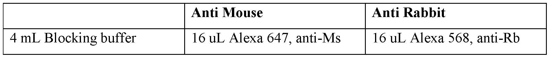
- HUVECs on Fibrin FtUVECs on fibrin are fixed for 20 minutes
- HUVECs on Fibrin HUVECs are blocked for 1 hr prior to primary stain.
- This protocol describes the preparation of several bioinks.
- a shake-ball can be added to improve mixing if desired
- Described herein is a perfusion system enclosure. It consists of two polycarbonate plates separated by a silicone gasket with luer lock fittings to allow for fluid to be pumped through the assembly.
- Figure 10 depicts the plate design.
- the silicone elastomer is highly viscous. Use a 50 mL serological pipet and be patient.
- the numbers expressing quantities of ingredients, properties such as concentration, reaction conditions, and so forth, used to describe and claim certain embodiments of the invention are to be understood as being modified in some instances by the term“about.” Accordingly, in some embodiments, the numerical parameters set forth in the written description and attached claims are approximations that can vary depending upon the desired properties sought to be obtained by a particular embodiment. In some embodiments, the numerical parameters should be construed in light of the number of reported significant digits and by applying ordinary rounding techniques. Notwithstanding that the numerical ranges and parameters setting forth the broad scope of some embodiments of the invention are approximations, the numerical values set forth in the specific examples are reported as precisely as practicable. The numerical values presented in some embodiments of the invention may contain certain errors necessarily resulting from the standard deviation found in their respective testing measurements.
- the terms“a” and“an” and“the” and similar references used in the context of describing a particular embodiment of the invention can be construed to cover both the singular and the plural.
- the recitation of ranges of values herein is merely intended to serve as a shorthand method of referring individually to each separate value falling within the range. Unless otherwise indicated herein, each individual value is incorporated into the specification as if it were individually recited herein. All methods described herein can be performed in any suitable order unless otherwise indicated herein or otherwise clearly contradicted by context.
Landscapes
- Health & Medical Sciences (AREA)
- Engineering & Computer Science (AREA)
- Life Sciences & Earth Sciences (AREA)
- Chemical & Material Sciences (AREA)
- Biomedical Technology (AREA)
- Zoology (AREA)
- General Health & Medical Sciences (AREA)
- Transplantation (AREA)
- Biotechnology (AREA)
- Bioinformatics & Cheminformatics (AREA)
- Genetics & Genomics (AREA)
- Organic Chemistry (AREA)
- Wood Science & Technology (AREA)
- Cell Biology (AREA)
- Materials Engineering (AREA)
- Manufacturing & Machinery (AREA)
- Animal Behavior & Ethology (AREA)
- Public Health (AREA)
- Veterinary Medicine (AREA)
- Epidemiology (AREA)
- Dermatology (AREA)
- Medicinal Chemistry (AREA)
- Oral & Maxillofacial Surgery (AREA)
- Microbiology (AREA)
- General Engineering & Computer Science (AREA)
- Biochemistry (AREA)
- Developmental Biology & Embryology (AREA)
- Botany (AREA)
- Chemical Kinetics & Catalysis (AREA)
- Vascular Medicine (AREA)
- Hematology (AREA)
- Urology & Nephrology (AREA)
- Apparatus Associated With Microorganisms And Enzymes (AREA)
- Materials For Medical Uses (AREA)
- Micro-Organisms Or Cultivation Processes Thereof (AREA)
Abstract
Bioprinting is the layer-by-layer construction of synthetic tissues or scaffolds. Described herein is a motorized extruder which can precisely extrude and retract extrudate such as bioinks in a compact and rapidly-loadable form-factor. This includes a compact bioprinter using a stepper motor coupled with a threaded shaft to directly move the plunger of an extruder. This pneumatic-mechanical system obviates the needs for pneumatic tubing, rods, or other complex elements of existing designs. The direct drive design further allows for a lighter, smaller gantry that is capable of more precise fabrication of bioprinted constructions. This includes delicate vasculature systems that are beyond limits of existing bioprinting technologies.
Description
COMPACT MECHANICAL SYRINGE EXTRUDER FOR 3D BIOPRINTING OF
CELL LADEN GELS
FIELD OF THE INVENTION
The described technology relates to a bioprinter system for fabricating systems including depositing cells in an organized fashion for analysis.
BACKGROUND
Bioprinting is the layer-by-layer construction of synthetic tissues or scaffolds in order to generate tissues with greater similarity to natural tissues for modeling organs (for research, such as drug discovery) and medicine (such as transplantation). While bioprinters exist on the market, including pneumatic and mechanical systems, they are significantly limited in precision and simplicity when exerting force to extrude materials on a surface, including bioinks with cells in a substrate. For example, pneumatic vacuum pressure through tubing may leak or transit through long pneumatic tubing is damaging to cells in bioink. Mechanical systems are bulky and need a large rod; a gantry surrounding the extruder is moved along the rod to exert pressure. There is a great need in the art for a system that achieves a series of criteria, including precision, retraction, compact size, rapid loading, and low cost.
Described herein is a motorized extruder which can precisely extrude and retract extrudate such as bioinks in a compact and rapidly-loadable form-factor. This includes a compact bioprinter using a stepper motor coupled with a threaded shaft to directly move the plunger of an extruder (e.g., syringe). This pneumatic-mechanical system obviates the needs for pneumatic tubing, rods, or other complex elements of existing designs. The direct drive design further allows for a lighter, smaller gantry that is capable of more precise fabrication of bioprinted constructions. This includes delicate vasculature systems that are beyond limits of existing bioprinting technologies.
SUMMARY OF THE INVENTION
Described herein is a bioprinter for dispensing at least one biomaterial, comprising s processor configured to determine a path; a support assembly, comprising one or more linear rods; a gantry comprising: at least one extruder, each extruder comprising a nozzle and a tube, a plunger, a threaded shaft, a stepper motor, wherein the processor is operatively coupled to the support assembly to move the one or more linear rods along a determined path, and operatively coupled to the stepper motor, wherein the one or more linear rods are attached to
the gantry , wherein the plunger is inside the tube and comprises a means for attachment to the threaded shaft, wherein the threaded shaft is mechanically coupled to the stepper motor, wherein the nozzle is at one end of the tube. In other embodiments, the means for attachment to the threaded comprises reciprocating members on each of the plunger and threaded shaft. In other embodiments, the reciprocating members are a snap fit coupling. In other embodiments, the bioprinter comprises two extruders. In other embodiments, the plunger is configured to exert pressure through the nozzle. Also described herein is a hioprinted assembly made by the bioprinter. In other embodiments, the hioprinted assembly includes vascular cells in an organized fashion deposited on a substrate. In other embodiments, the hioprinted assembly includes one or more non-vascular cells. In other embodiments, the non-vascular cells are derived from induced pluripotent stem cells (iPSCs).
Also described herein is a bioprinted assembly, comprising a layer of vascular cells in an organized fashion deposited on a substrate n other embodiments, the bioprinted assembly includes induced pluripotent stem cell endothelial cells (iECs). In other embodiments, the bioprinted assembly includesone or more non-vascular cells. In other embodiments, the bioprinted assembly includes non-vascular cells are derived from induced pluripotent stem cells (iPSCs).
Also described herein is a bioink, including a quantity of at least one cell type suspended in a substrate suitable for bioprinting. In other embodiments, the bioink includes induced pluripotent stem cell endothelial cells (iECs). In other embodiments, the bioink includes one or more non-vascular cells. In other embodiments, the non-vascular cells are derived from induced pluripotent stem cells (iPSCs). In other embodiments, the substrate comprises one or more of cell culture media, gelatin and fibrinogen.
BRIEF DESCRIPTION OF THE FIGURES
Figure 1. Various perspectives of an embodiment. As shown, the bioprinter includes a motorized extruder (A) that obviated the needs for a bulky linear rail system (B). Instead of coupling a threaded shaft to a fixed shaft on a stepper motor, the stepper motor turns a threaded shaft directly. The syringe snaps into place (C), and the plunger itself couples to the shaft with a snap-fit coupling (D).
Figure 2. Manual plunger extension. Manual plunging of the syringe for loading and unloading (A) is achieved with a plunger extension that couples to the miniaturized plunger using the same snap coupling (B) as the motor.
Figure 3. Bioinks containing induced pluripotent stem cells. Bioinks as shown in 6-well place (A), Bioink containing cell culture medium, gelatin, and fibrinogen (B). At 37C, this ink can be pipetted to suspend cells and fill a syringe (C). At room temperature it gels, allowing it to be built upon (D). Silicone can be printed to form scaffolds and microfluidic devices.
Figure 4. Stem cell-containing bioink at 4X magnification.
Figure 5. Another depiction of assembly together. Another depiction of the assembly showing the stepper motor, threaded shaft, with snap-fit coupling to syringe (A). Another depiction stepper motor, threaded shaft and syringe, as controlled by circuit board (B).
Figure 6. Depiction of twin extruder. An advantage of the system is that the simplified construction allows for multiple extruders to be assembled together, as shown in (A). In another perspective, the extruder is mounted on the assembly (B).
Figure 7. Exemplary results. The printer and ink achieved excellent detail, which has continued to improve as settings are optimized (A). An initial printed construct two days after printing (B) and 6 days after printing (C) retained shape. A taller print immediately after printing (D) and after three days (E) also showed excellent cell survival. Printed nuclear GFP stem cells under fluorescence, 3 days post printing (F) were visible inside of the 3 mm tall structure.
Figure 8. Depiction of items used in the process.
Figure 9. Depiction of items used in the process.
Figure 10. Depiction of the plate design.
Figure 11. Stepper motor compatible with the bioprinter.
DETAILED DESCRIPTION
All references cited herein are incorporated by reference in their entirety as though fully set forth. Unless defined otherwise, technical and scientific terms used herein have the same meaning as commonly understood by one of ordinary skill in the art to which this invention belongs. Singleton et al., Dictionary of Microbiology and Molecular Biology 3rd ed. , Revised , J. Wiley & Sons (New York, NY 2006); and Sambrook and Russel, Molecular Cloning: A Laboratory Manual 4th ed., Cold Spring Harbor Laboratory Press (Cold Spring Harbor, NY
2012), provide one skilled in the art with a general guide to many of the terms used in the present application.
One skilled in the art will recognize many methods and materials similar or equivalent to those described herein, which could be used in the practice of the present invention. Indeed, the present invention is in no way limited to the methods and materials described.
3D bioprinting allows researchers to construct synthetic tissues that replicate the structure and environment of living mammalian tissues far better than planar cells on a plastic dish can. Cells of many kinds can be deliberately arranged to study cell-cell interactions, and can also be vascularized to model cellular interactions in a manner not otherwise accounted for in traditional cell culture formats. This has the potential to create models which recapitulate natural functions: blood brain barrier models for drug permeability studies; kidneys with functional nephrons; bulk liver tissues with ducts; synthetic pancreas with working islets.
In addition to depositing various cell types, 3D bioprinting can also be used to build soft, biocompatible structures for study biophysical and biomechanical effects. For example, permeable scaffolds can be printed to study osteoclast migration. Soft domes can be made to support corneas in culture.
As bioprinting advances, its use is likely to be adopted throughout biomedical research to replace materials and methods which are currently employed simply due to a lack of available alternatives. Importantly, existing techniques are in capable of precise deposition of cells in a manner nearing relevant physiological distances. Specifically, precision deposition of stem cells requires that the printhead be as small and light as possible in order to reduce the inertia the gantry must contend with. Traditional designs are too bulky to approximate vasculature on printed surfaces, with such physiological features being an important feature to incorporated if one is to faithfully model living systems.
While achieving a small size can be done by relying on a pneumatic system (since this offloads the mechanics from the gantry completely), but doing so is extremely expensive and one must contend with issues related to stable sealing for pressure generation and maintenance, along with pneumatic tubing transit that is damaging to cell viability. Only top-tier machines can achieve retraction, which is vital to prevent leakage.
Mechanical systems offer precision, retraction, and can be made rapidly-loadable. But the size is prohibitive, since available options drive a plunger along rails, which requires the entire length of the plunger to be available between the motor and the back end of the syringe. Gantry sizes also tend to be larger in such systems.
Described herein is a motorized extruder that overcomes size limitations by removing the bulky linear rail system. Instead of coupling a threaded shaft to a fixed shaft on a stepper motor, the stepper motor turns a threaded shaft directly. The syringe snaps into place, and the plunger itself couples to the shaft with a snap-fit coupling. Manual plunging of the syringe for loading and unloading is achieved with a plunger extension that couples to the miniaturized plunger using the same snap coupling as the motor.
A key advantage for a mechanical drive over pneumatic is that the pneumatic response varies with ink viscosity, and will undesirably eject completely if the pressure is set slightly too high. Pneumatic systems also require additional hardware to back-drive in order to retract extrudate, which is a common and important feature in conventional FDM printing that mechanical extruders perform without challenge.
As a renewable and flexible source of cellular materials for printing, Induced Pluripotent Stem Cells (iPSCs) ideal for bioinks. Nevertheless, iPSCs are highly sensitive to their environment. In order to prevent contamination and limit the time spent during printing, it is necessary to be able to load bioinks as quickly as possible and with minimal exposure to possible sources of contamination. Meeting these needs while keeping the size of a print head low enough to print successfully in a sterile environment requires a system with precision, retraction, compact size, rapid loading, and low cost.
Described herein is a bioprinter for dispensing at least one biomaterial, comprising s processor configured to determine a path; a support assembly, comprising one or more linear rods; a gantry comprising: at least one extruder, each extruder comprising a nozzle and a tube, a plunger, a threaded shaft, a stepper motor, wherein the processor is operatively coupled to the support assembly to move the one or more linear rods along a determined path, and operatively coupled to the stepper motor, wherein the one or more linear rods are attached to the gantryy wherein the plunger is inside the tube and comprises a means for attachment to the threaded shaft, wherein the threaded shaft is mechanically coupled to the stepper motor, wherein the nozzle is at one end of the tube. In various embodiments, the tube and plunger are configured to exert pressure through the nozzle. For example, extruding a bioink through the nozzle at the end of the tube. In various embodiments, the processor operatively coupled to the stepper motor mechanically attached to the threaded shaft with a means for attachment to the plunger in the tube, thereby controls exerted pressure through the nozzle of the tube. In other embodiments, the means for attachment to the threaded comprises reciprocating members on each of the plunger and threaded shaft. In other embodiments, the reciprocating members
are a snap fit coupling. In other embodiments, the bioprinter comprises two extruders. In other embodiments, the plunger is configured to exert pressure through the nozzle. As an example, a compatible stepper motor includes a hybrid lincear actuator motor such as MPN ROB-10848 as depicted in Figure I I . In various embodiments, the threateded shaft is about 5, 6, 7, 8, 9, 10, 11, 12, 13, 14, or 15 era long with a shaft traveling 0.001-0.005, 0.005-0.01, 0 01-0 02 mm/step, about 50-100, 100-200 steps per revolution. For example, the threaded shaft is 10 cm long with an M5 PI shaft that travels 0.01 mm/step, 200 steps per revolution. In various embodiments, compatible syringes range from 3mL to 10 mL.
Also decribed herein is a method of using the bioprinted, including the process outlined i n Example 1 .
Also described herein is a bioprinted assembly made by the bioprinter. In other embodiments, the bioprinted assembly includes vascular cells in an organized fashion deposited on a substrate. In other embodiments, the bioprinted assembly includes one or more n on-vascular cells. In other embodiments, the non-vascular cells are derived from induced pluripotent stem cells (iPSCs). In various embodiments, the bioprinted assembly includes a bioink. Examples of compositions of bioinks include Firbrinogen-Gelatin (F-G) Bioink, Firbrinogen-Gelatin-Thrombin (F-G-T) Bioink, and Pluronic F-127 as listed in Tables 11, 12, and 13. This includes constructs according to the process and designs outlined i n Example 1.
Also described herein is a bioprinted assembly, comprising a layer of vascular ceils in an organized fashion deposited on a substrate. In other embodiments, the bioprinted assembly includes induced pluripotent stem cell endothelial cells (iECs). In other embodiments, the bioprinted assembly includes induced pluripotent stem cell brain micro-vascular endothelial ceils (iBMECs). In other embodiments, the bioprinted assembly includes one or more non- vascular cells. In other embodiments, the bioprinted assembly includes non-vascular cells are derived from induced pluripotent stem cells (IPSCs). As one example, this include induced motor neurons (iMNs), pancreatic cells, or skin fibroblasts. In other embodiments, the organized fashion includes a vascular network defining at least one central channel, wherein the vascular network is positioned in a selected pattern to define void space. In various embodiments, the non-vascular cel ls are within the void space. In another embodiment, vascular network is configured to permit diffusion of a liquid, such as cell culture media, from the at least one central channel to non-vascular cells. In other embodiments, the substrate includes one or more pre-printed constructs in an organized fashion. In various embodiments, the pre-printed constructs include a bioink Examples of compositions of bioinks include
Firbrinogen-Gelatin (F-G) Bioink, Firbrinogen-Gelatin-Thrombin (F-G-T) Bioink, and Pluronic F-127 as listed in Tables 11, 12, and 13. In various embodiments, the pre-printed constructs include polymers, such as thermosensitive or light sensitive polymers, gel matrices, or other biocompatible materials readily known to one of skill in the art. In various embodiments, the one of more vascular ceils are in a construct of larger than 100-200, 200- 400, 400 or more mhi. In various embodiments, the vascular network defining at least one channel includes channels of less than 100-200 pm.
Also described herein is a bioink, including a quantity of at least one cell type suspended in a substrate suitable for bioprinting. In other embodiments, the bioprinted assembly includes induced piuripotent stem cell endothelial cells (IECs). In other embodiments, the bioink includes induced piuripotent stem cell brain microvascular endothelial cells (iBMECs). In other embodiments, the bioink includes one or more non- vascular cells. In other embodiments, the non-vascuiar cells are derived from induced piuripotent stem cells (iPSCs). As one example, this include induced motor neurons (iMNs), pancreatic cells, or skin fibroblasts.
In another example, iECs can be made by culturing (iPSCs) in the presence of CHIR99012 for about 2 days to generate mesoderm, culturing mesoderm in the presence of BMP4, VEGF, and FGF2 for about 2 days to generate vascular progenitor cells, culturing vascular progenitors in the presence of EGM-MV2 and VEGF for about 4-6 days to generate endothelial progenitor cells, and culturing endothelial progenitor cells in the presence of EGM- MV2 and VEGF to generate endothelial cells. In various embodiments, the vascular progenitors are cultured in the presence of EGM-MV3 and VEGF, and passages 2, 3, 4 or more times to generate endothelial cells. For example iECs can express key markers such as CD31, CD34, VEGF, and VEGF A. Using a combination of growth factors, the Inventors were able to successfully produce endothelial cell types. Based on the described protocols, it appears that endothelial markers are more and purely expressed in Day 20 compared to Day 10 of differentiation -> time for maturation. Differentiation to be confirmed with other experiments: Dil-ac-LDL uptake, and TEER (resistance). Further information is found in PCT App. No. US2019/23749, which is fully incorporated by reference herein.
In other embodiments, the substrate comprises matrix components or hydrogels. In various embodiments, hydrogels include natural hydrogels such as collagen, fibrin, chitosan, and alginate and synthetic hydrogels such as gelatin, Pluronic, and polyethylene glycol. In other embodiments, the substrate comprises a thermosensitive or light sensitive polymer. In
other embodiments, the substrate comprises one or more of cell culture media, gelatin and fibrinogen. Examples of compositions of bioinks include Firbrinogen-Gelatin (F-G) Bioink, Firbrinogen-Gelatin-Thrombin (F-G-T) Bioink, and Pluronic F-127 as listed in Tables 11, 12, and 13.
Example 1
Bioprinting may enable researchers to overcome limitations of current methods to construct macro-scale structures, organize different cell types together, and generate very specific shapes. To overcome size limitations, bioprinting is accomplished by generating a 3D computer model; generating a series of cross-sections of the model; then instructing a printhead to draw each cross-section and deposit material to construct the original 3D shape layer-by- layer.
Example 2
Bioprinter incorporating stepper motor and threaded shaft As shown in Figure 1, the bioprinter includes a motorized extruder that obviates the needs for a bulky linear rail system. Whereas conventional designs couple a threaded shaft to a fixed shaft on a stepper motor, the stepper motor turns a threaded shaft directly. This obviates the need for pneumatic vacuum pressure systems and also reduces the gantry size, which allows for higher precision printing due to decreased weight removal of components that otherwise reduce tolerances due to mechanical play. The threaded shaft snaps into place for a plunger on a syringe, eliminating another source of mechanical play, by using a snap-fit coupling. The shap-fit coupling also allows easy loading and re-loading by providing for manual plunging of the syringe as shown in Figure 2. Using a plunger extension that couples to the miniaturized plunger, the same snap coupling as the motor allows easy swapping. Another depiction of assembly together is shown in Figure 5, including the stepper motor, threaded shaft, with snap- fit coupling to syringe.
Example 3
Assembly and twin extruder design
An advantage of the system is that the simplified construction allows for multiple extruders to be assembled together, as shown in Figure 6. In another perspective, the extruder is mounted on the assembly. In these designs, one could load two different bioink cell types in each extruder, or a cell type and other mechanical substrate in each extruder, with sequential
or parallel fabrication, obviating the need to change bioinks/mechanical substrates, as is needed in conventional systems.
Example 4
Bioinks
Bioinks are printable materials that can be extruded from a nozzle as liquids, but then stiffened sufficiently to support the weight of successive layers on top of them. We tested a bioink containing cell culture medium, gelatin, and fibrinogen. At 37C, this ink can be pipetted to suspend cells and fill a syringe. At room temperature it gels, allowing it to be built upon. Silicone can be printed to form scaffolds and microfluidic devices. Exemplary results and views are shown in Figures 3 and 4.
Example 5
Preliminary Results
The printer and ink achieved excellent detail, which has continued to improve as settings are optimized (A). An initial printed construct two days after printing (B) and 6 days after printing (C) retained shape. A taller print immediately after printing (D) and after three days (E) also showed excellent cell survival. Printed nuclear GFP stem cells under fluorescence, 3 days post printing (F) were visible inside of the 3 mm tall structure. Exemplary results and views are shown in Figure 7.
Example 6
Printing vasculature
Very small and intricate vessel patterns are reportedly among the most difficult to fabricate, but are of high interest as needed for faithfully modeling living systems. The aforementioned bioprinter can support physical design organization of vasculature with superior fabrication results of bioprinted constructions owing to its unique design. In another example, the Inventors use induced pluripotent stem cell brain microvascular endothelial cells (iPSC-BMECs) as superior to human umblinical vein endothelial cells (HUVECs), with iPSCs- BMECs based on barrier function, enhanced electrical resistance, ability to be cryopreserved, among others. This confers specific advantages when using cells as a consumable for bioprint constructions. Such advantages include consistent cell source between bioprinted constructions and reliable availability.
Example 7
Exemplary Bioprinting method
This protocol describes the basic process of printing a first-generation vascularized system. Major steps include:
1. Loading bioinks
2. Printer setup
3. Printing
4. Matrix casting
5. Connecting flow
6. Maintenance
0. Checklist
1. Inks
a. Dissolve and filter fibrinogen.
See ink preparation protocol for details.
b. Load Pluronic F-127 into the appropriate syringe
i. Typically, 3 mL is sufficient for several tests and prints.
ii. Prepare an additional syringe of Pluronic for post-print adjustment c. Chill PBS
Place in the freezer of Grandmama ~3 hrs prior to use.
d. Begin thrawing Thrombin, Transglutaminase, and possibly acutase and FBS.
2. Hardware, autoclaved, are shown in Table 1.
Table 1. Sterile components
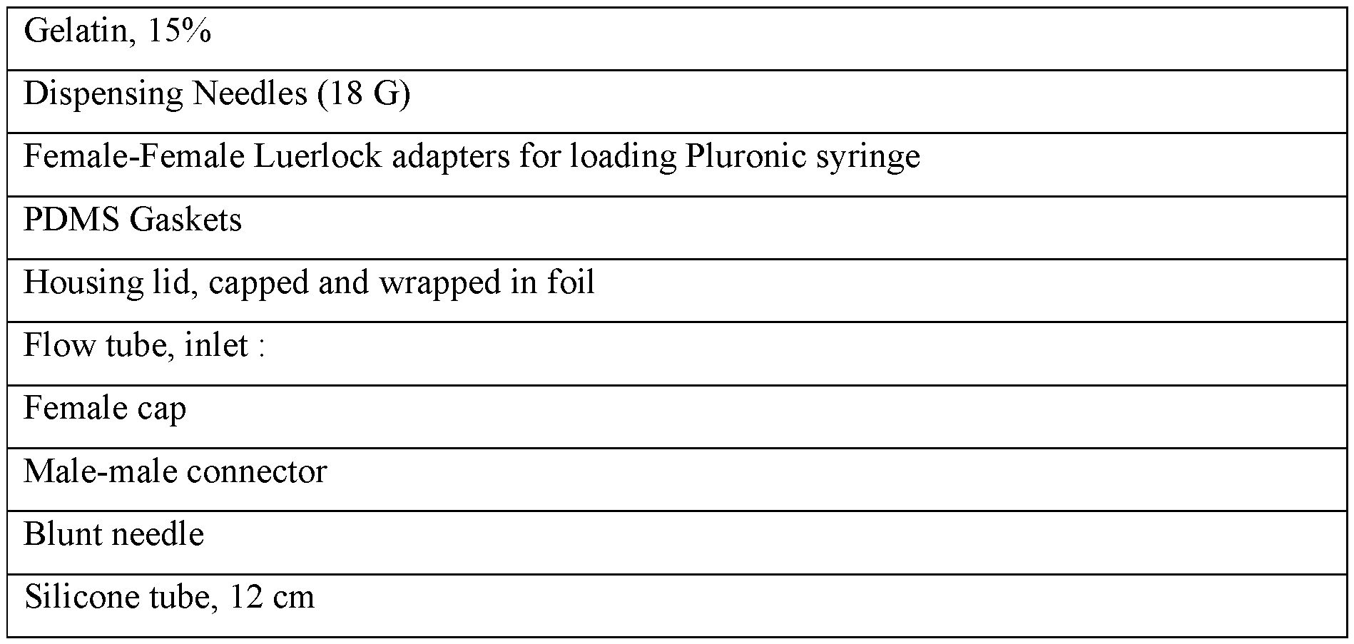

Figure 8 depicts items used in the process.
3. Hardware, not autoclaved, as shown in Table 2.
Table 2. Other components
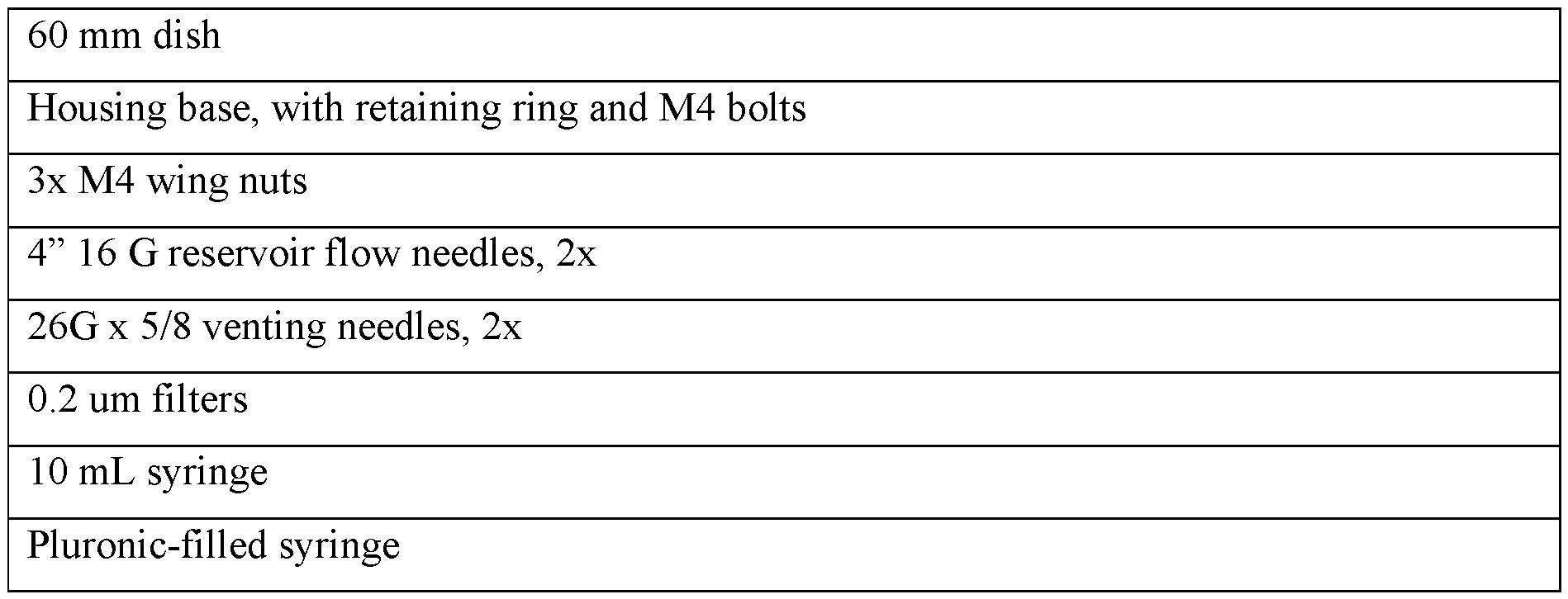
Figure 9 depicts items used in the process.
4. Reagents are shown in Table 3.
Table 3. Bioprinting reagents


1. Cap lid ports and wrap in aluminum foil.
2. Prepare inlet and outlet flow tubes and place in an autoclavable box.
3. Rinse a gasket and place it in an autoclavable box, along with a syringe shaft with coupler
4. Load a pipet tip box with several 18 G dispensing needles, caps, and female-female Luer lock adapters. l.b. Dissolve Fibrinogen
1. Weight out 100 mg of fibrinogen and add to a 50 mL conical tube.
Attempt to break large pieces apart if possible to improve dissolution. Fibrinogen is kept in Pugsly, Bin_03. Use a 50 mL conical tube to enable filtration with a steriflip tube later.
2. Add 4.5 mL of DMEM (or the appropriate base medium).
3. Add 100 uL of PS A.
4. Add 100 uL of 250 mM CaCl2
5. Vortex and incubate for 30 minutes at 37 C.
Don’t push the tube to the bottom of the bead bath: it may overheat.
6. Attach a steriflip filter and degas for several minutes to reduce bubbles.
7. Remove vacuum and gently invert the steriflip tube, then restore vacuum to filter.
2. Add Gelatin to Fibrinogen
1. Add 5 mL of autoclaved 15% gelatin to the dissolved and filtered fibrinogen.
2. Mix and incubate another 30 mL at 37C.
3. 30 minutes before use, add 600 uL of 50 mg/mL transglutaminase.
3. Load Pluronic F-127 into print syringes
1. In the hood, draw out the plunger from a 5 mL syringe and transfer the rubber cap to a printed printer
plunger. Sterilize with ethanol.
2. Attach a plunger adapter to the printer plunger and fully insert the plunger.
3. Uncap a chilled storage syringe of 30% Pluronic F-127 and add a sterile female-female Luer lock
adapter. Press the plunger to fill the adapter before coupling the empty 5 mL syringe.
4. Gently fill the empty syringe vertically, with the empty syringe on top, so that any bubbles rise
towards the plunger and away from the nozzle.
5. Fill a 1 mL syringe for post-print adjustment, then cap all syringes. Return the storage syringe to the
refrigerator and place the 5 mL print syringe in the printer to acclimate to room temperature.
The pluronic F-127 will gel quickly inside of the tube. This is fine: it does not need to be liquid to print.
3.b. Load Bioinks - BIO X
Pluronic -127
1. In a hood, connect a loading syringe full of pluronic F-127 to a CELLINK print
syringe.
2. UNCAP THE BACK OF THE PRINT SYRINGE
3. Gently load the print syringe vertically, so that any bubbles rise away from the nozzle and recap both syringes.
4. Print Sacrificial Scaffold
1. Turn on printer and computer.
2. Open the Repetier Host print server and press“Connect” if the printer doesn’t
automatically connect.
3. Load a .geode file prepared in Cura.
4. Home the printer and set a dish on the stage. If a 5 mL syringe hasn’t been loaded, load it now.
5. Press button“1” to move the printhead into position 1.
6. Uncap the syringe and attach an 18 G plastic syringe.
18 G has been the standard channel size, but can be modified in Fusion 360 through geometric
dimensions or in Cura through flow. Both plastic and metal nozzles have been used successfully,
however plastic has become the standard through practice.
7. Press button“2” to extrude 0.5 mm. Repeat until extrudate emerges.
8. Pass a small kimwipe below the nozzle to catch and remove the hanging extrudate.
Extrudate will continue to slowly emerge for several seconds after the motor command is issued. Remove the extrudate after it has stopped emerging in order to leave minimal extra extrudate hanging from the nozzle.
9. Adjust the bed-nozzle distance with the Z-control buttons until the nozzle is just barely touching the plastic dish.
Improper starting distance is the primary cause of print failures.
5. Prep cells
1. Accutase or trypsinize cells and dilute in a 50 mL syringe
2. Count the cells and spin down gently.
3. Aspirate the supernatant and gently resuspend cells in bioink using a 50 mL serological pipet. Approximately 5 mL is appropriate for a gen. 3 perfusion system.
4. Maintain cell-impregnated ink at 37 C until ready to cast. Attempt to use as soon as possible.
Lewis Bioink / Atala Bioink / Gelatin dummy ink
1. In a hood, open a 5 mL syringe and remove the plunger.
2. Replace the original plunger with a sterilized coupler plunger.
Make sure to use the plunger sized for your purposes. A standard 4 mL plunger is recommended for the standard 4mL construct print.
3. Attach a sterilized 18 gauge plastic needle tip.
4. Insert the plastic needle into the bioink solution and draw until the back of the coupling reaches its appropriate starting position. Avoid entraining bubbles.
3.a. Printer Setup - SL- Vertex Bioprinter
1. Open MatterControl
a. The printer should connect automatically. If not, see Appendix A: troubleshoting
2. Load an STL or geode file into the queue
a. If it is an STL, select“Edit” to center it on the print bed. Printing geode is recommended, as geode files can be prepared in Cura, a more feature-rich application.
3. Home all axes by navigating to“Control” and selecting“Home all Axes”
4. Move the print head to the center of the bed by selecting 100 as the move distance and moving it down and to the left.
5. Load inks by manually turning the threaded motor shafts until the bottom of the
coupler is just above the top of the syringe slot, with its opening facing outward. The syringe should slot into the syringe slot. The plunger-end coupler should interface with the motor-end coupler without resistance.
3.b. Printer Setup - BIO X
1. Prepare the print file as an STL or geode
2. Insert a USB drive containing the print files and select“Bioprint”
Current successful settings
File: Week 28/Vasculature 5 arcs 0.6 mm.stl
Pressure: 90 kPa
Speed: 10 mm/s
Diameter: 0.95 mm
Layer Height: 0.7 mm
First Layer: 0.7 mm (needs Z-hop)
4. Casting
1. Immediately after printing, cover the print by replacing the dish lid
2. Move the dish into the hood.
3. Add an appropriate amount of pluronic to the ports of the lid on the interior face and gently seat the lid.
4. Screw the wingnuts onto the screws without tightening.
5. Uncap both fill ports and attach a female-female Luer lock adapter to one.
6. Spin down cells in a 50 mL conical tube
7. Aspirate the supernatant and add 5 mL of warm GFT bioink.
8. Add 150 uL of 100 U/mL Thrombin on top of bioink.
9. Using a 25 mL serological pipet, triturate the bioink, cells, and thrombin until well mixed. Working time varies, particularly based on the storage time of the Thrombin. This concentration should easily allow at least 10 seconds of working time without noticeable effect. Approximately 30 seconds of working time is expectable before crosslinking begins to become observable, and another minute before cross linking fully inhibits pipetting.
10. Dispense cell-laden ink into the Luer lock adapter, tilting the plate slightly to
encourage the ink to spread to the far sides of the pluronic vascular towers.
11. Once the housing is nearly full, dispense the remaining cell laden ink into a 60 mm dish.
12. Remove the female-female adapter and cap this port.
13. Gently tighten the screws to compress the housing. This will compact the headspace and force some bioink out of the remaining uncapped fill port. Wipe this away and cap the uncapped fill port.
14. Transfer the housing and the dish with excess cell ink into the refrigerator and start a timer for 20 minutes.
Printing
1. Fill a syringe with 30% Pluronic F-127
2. Load the syringe into the first extruder
3. Run a test print
4. Place the gasket in the shallow dish lid using the gasket placing tool.
5. Add warm agar
6. Set the dish aside
Collection
1. Label appropriate tubes
2. Prepare an appropriate volume of paraformaldehyde (1.75 mL of 32% in 12.25 mL PBS)
3. Shut off the pump.
4. Release the tube restraint.
5. Move the housing and both reservoirs out of the incubator and onto a bench top.
6. Disengage the Luer lock fittings connected to the perfusion housing.
7. Unscrew the wing nuts to release the lid.
8. Transfer the construct into the slicing jig.
9. Section the construct. Using a spatula, transfer the sections into a dish for fixation.
10. Rinse once with PBS, then cover in 4% paraformaldehyde for 20 minutes.
11. While fixing, disassemble reservoirs and flow lines:
a. Fill a 5 mL syringe with DI water
b. Remove and discard needles and filters
c. Examine septa. If reusable, rinse and dry. Otherwise, discard.
d. Flush silicone tubing with DI water and dry.
12. Aspirate the PFA and rinse in PBS three times.
13. Using a spatula, transfer sections into labeled tubes.
Appendix I
Printer Setup
1. Open MatterController and select your model.
2. Click“Edit”. The printer will suggest centering your model. Accept, then save.
3. If necessary, adjust dimensions and save.
4. Connect the printer if it is not already connected
5. Set the feed rate with the command M92 E3000
6. Home the printer.
7. Manually set the Z home.
8. Load a syringe of pluronic F-127 in the appropriate extruder. The left default is extruder 1, which is the default extruder.
9. Purge the nozzle slightly by twisting the drive screw until pluronic F-127 comes out.
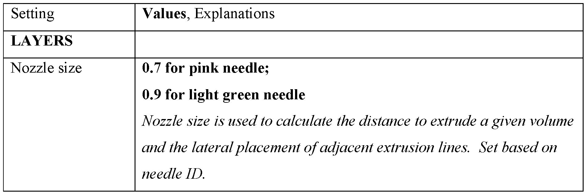
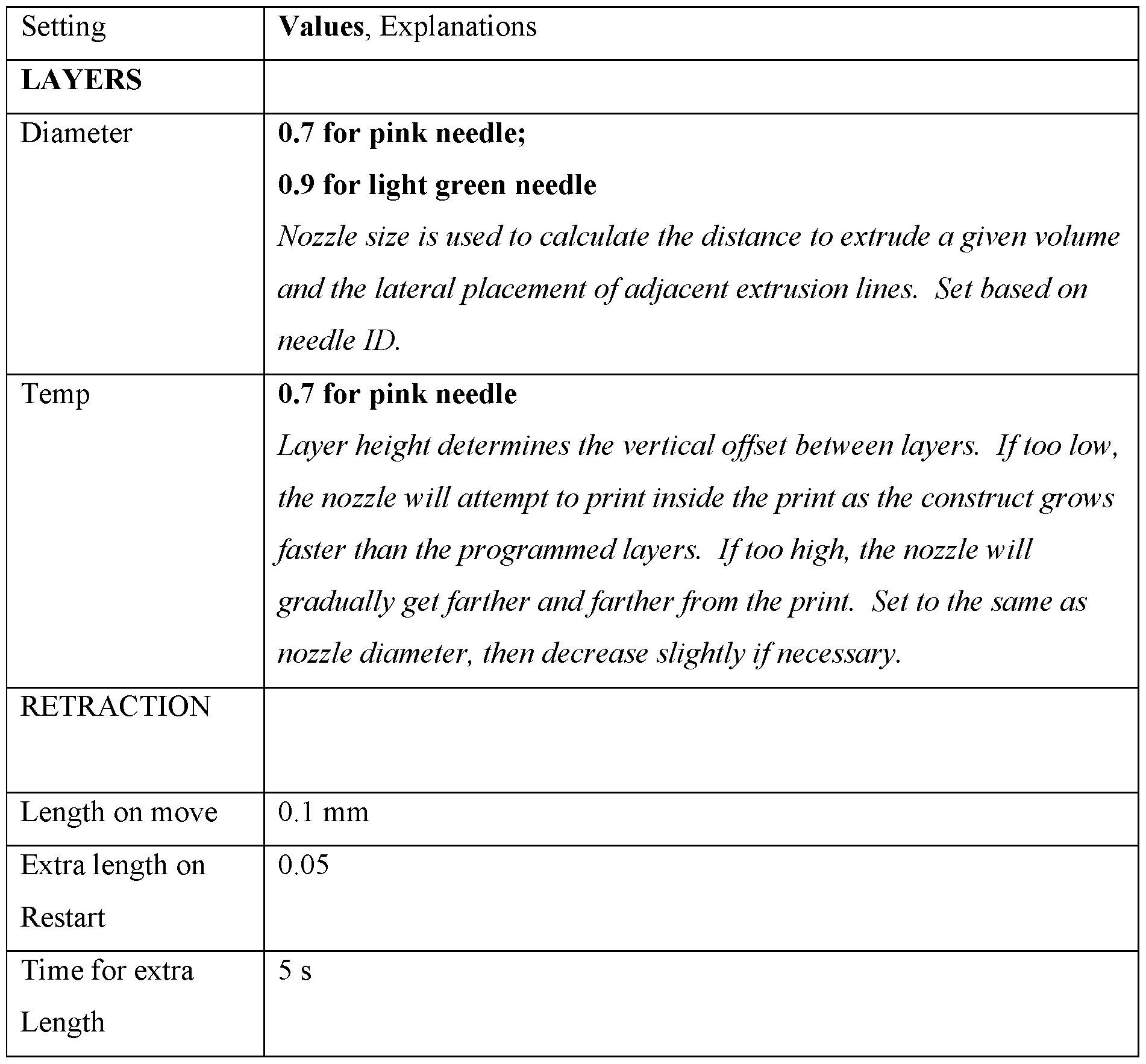
Print Settings
General settings for printing are shown in Table 4.
Table 4. Print settings


Filament Settings are shown in Table 4a.
Table 4a. Filament Settings

Designing the Construct
Construct design begins with a concept and then proceeds through a series of refinement steps. The standard construct used in this design was started with the decision to have two towers connect to ports on a lid, and to connect those towers by several lateral channels. An initial construct based on these principles was modeled, and then a gasket was designed around the construct.
Following the design of the first draft of a construct, a mold of the gasket was printed in PL A and used to cast PDMS. The production of a working gasket and enclosure prompted later construct designs to fit key dimensions to these reusable parts.
Key dimensions are the distances between the tower and the width of the gasket. The number of channels, the width of the channels, the shape of the channels, and the diameter of the towers were adjusted iteratively.
Channel width: The channel width must be compatible with the nozzle diameter specified in the sheer. If channels are thinner, the sheer will not lay a path along them. If channels are too wide, the sheer will lay down multiple lines along each channel. To set the right channel width, select a nozzle size; optimize print settings for this nozzle size; then used the resulting optimal nozzle size parameter to define the width of channels in CAD.
Channel number: Greater channel numbers increases the bulk flow through the construct until the tower diameter is more constricting than the channels. Based on slicing habits, though, excessive more channels may increase the possibility of dead channels: those that don’t effectively connect along a continuous path from inlet to outlet.
Channel shape: Arcing channels were selected because angled channels with straight lines were prone to distortion and dragging as the printhead moved.
Hardware Guide
Dispensing Needles
Typically green plastic 18 G dispensing needles (autoclaved). These have an outlet ~l mm in diameter. Slicing profiles for the SL Vertex usually assume _ 0.8 mm diameter, with a flow of 1.2 or 1 mm with a flow of 1. When printing on the BIO X, the nozzle diameter is set for _ 0.8 mm with a pressure of _ or 1 mm with a pressure of _ .
23G - 0.432 mm (432 um) Orange tip
20G - 0.660 mm (660 um) Pink tip
18G - 0.965 mm (965 um) Green tip
Example 8
Staining and imaging bioprinted constructs
Solutions
Live/Dead Stain
50 uL of 1 mM stock Calcein in DMSO - Dilute 50 ug Calcein in 50 uL
DMSO
2 mL of 4 uM Ethidium Homodimer / 2 uM Calcein- To 2 mL of PBS, add:
4 uL of 2 mM Ethidium
Homodimer
4 uL of 1 mM Calcein
2 mL of 5 uM Propidium Iodide + 2 uM Calcein - To 2 mL of PBS, add:
6.6 uL of lmg/mL Propidium
Iodide
4 uL of 1 mM Calcein
4% Paraformaldehyde
12.25 mL PBS + 1.25 mL 32% Paraformaldehyde
Blocking & Permeabilization Buffer
2 mL / section. 10 mL recommended.
9 mL PBS
1 mL Donkey Serum
15 uL Triton X
Wash Buffer
100 uL TWEEN in 100 mL PBS
Hoescht Stain 33342 (w/ 2ndary Abs)
2 uL Hoescht in 5 mL PBS
Common Primary Antibodies:
iPSCs can be characterized using surface antigen antibodies listed in Table 5.
Table 5. iPSC characterization antibodies

Table 6.
Table 6. Induced motor neuron characterization antibodies

Table 7. Antibodies for characterizing other cell types

Secondary Ab stains for the aforementioned antibodies are listed in Table 8.
Table 8. Secondary antibodies
Staining
Wave length Name Target Section A Section B
Section C
405 (Blue) DAPI DNA
488 (Green) GFP Nuclear?
568 (Orange) Cy3/TritC Ms 1° Ab SSEA4 Tra 1 81 Tra 1 60
647 (Red) Cy5 Rb 1° Ab OCT4 SOX2 Nanog
Sectioning
Section the construct using a sectioning jig. Transfer the slices into a 60 mm dish or 6-well plate and rinse in PBS.
Viability Staining
1. Incubate sectioned constructs in Live/Dead staining dyes for 30 minutes at RT
2. Rinse three times in PBS
3. Image. Including excitation and emission values are listed in Table 9.
Table 9. Visualization
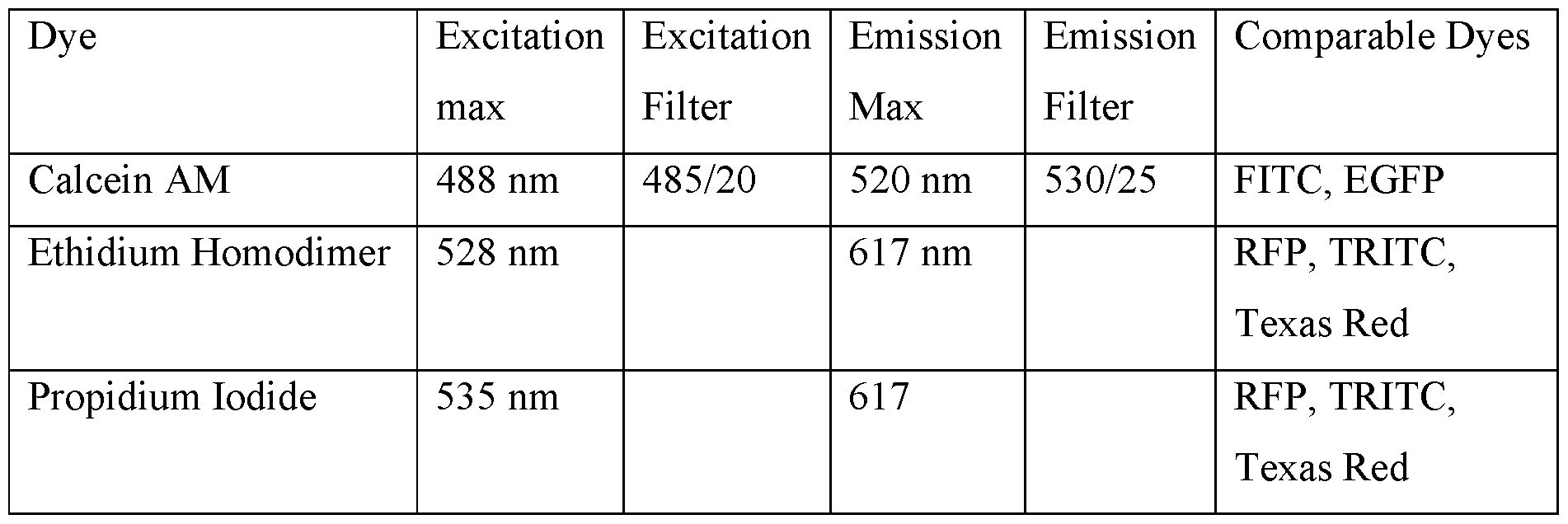
• Propidium iodide, EthD-l, and scaffold samples in Bin 1 Pugsly, calcein in Fester
Fixing
Initial fixation was performed overnight, but later fixations have been incubated for 30 minutes to avoid overcrosslinking and reducing permeability. Rinse 3x and store in PBS. HUVECs on Fibrin: FtUVECs on fibrin are fixed for 20 minutes
Staining, IHC
1) Block and Permeabilize
Submerge sections in blocking & permeabilization buffer overnight at 4 C. HUVECs on Fibrin: HUVECs are blocked for 1 hr prior to primary stain.
2) Rinse once with PBS.
3) Stain with Primary Antibodies
Incubate overnight at 4C.
4) Wash three times with PBS + TWEEN
Incubate at room temperature for five minutes between washes.
5) Stain with Secondary Antibodies
Spin down secondaries before preparation.
Incubate for two hours at room temperature, shielded from light.
6) Wash with PBS
7) Stain with Hoescht or DAPI
8) Rinse
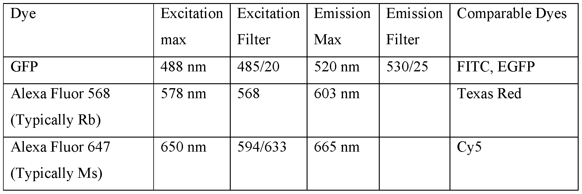
Imaging
After staining with Viability stain or antibodies stains, Place the samples on glass slides <?> Current attempts have placed sections in glass slides, which have the advantage of letting gravity firmly set them in place, but the disadvantage of allowing evaporative drying to warp the sample. An attempt to image in a well filled with PBS caused difficulties focusing, but is worth subsequent attempt.
Table 10. Visualization
Example 9
This protocol describes the preparation of several bioinks.
Reagents
Table 11. Firbrinogen-Gelatin (F-G) Bioink

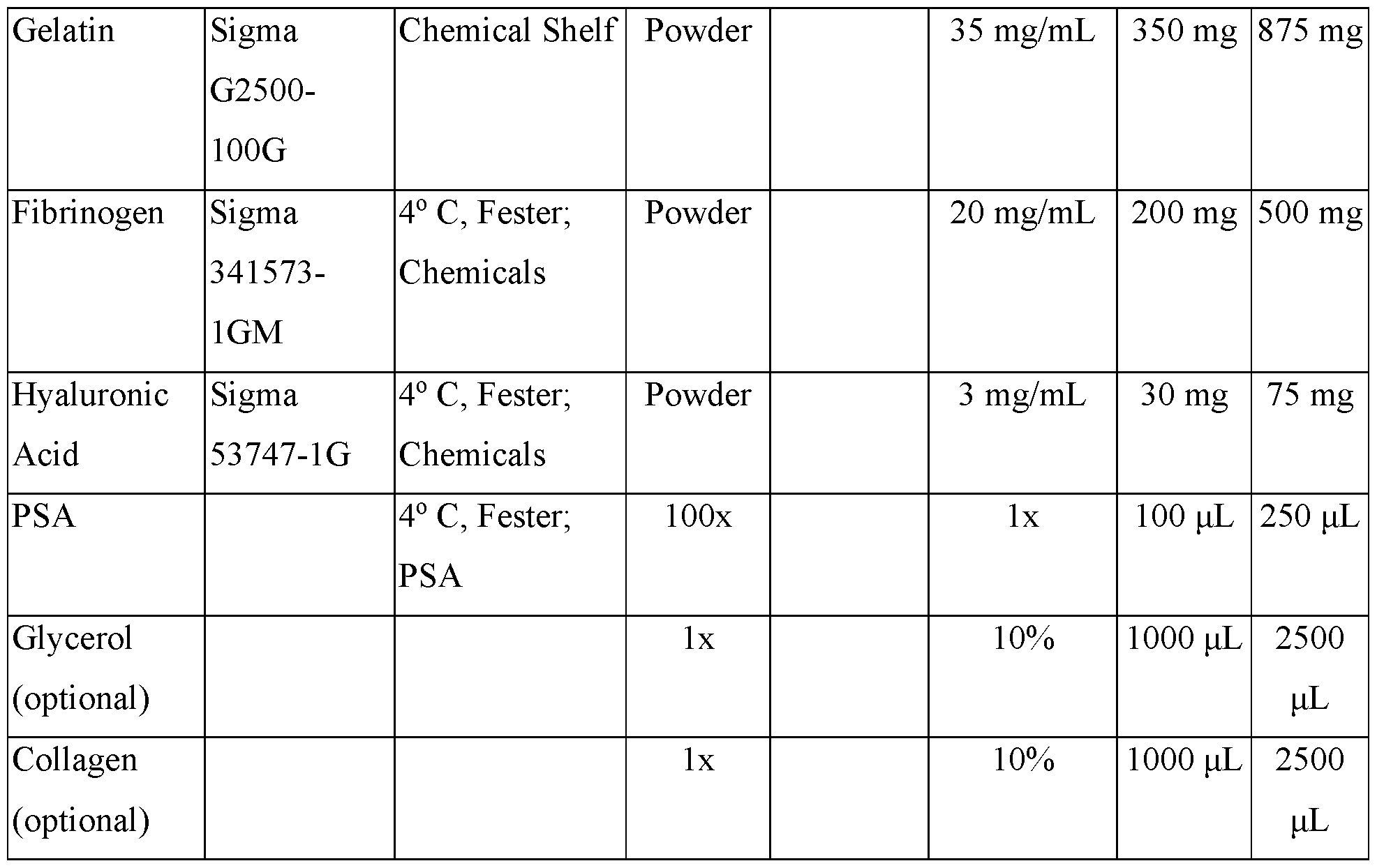
Table 12. Firbrinogen-Gelatin-Thrombin (F-G-T) Bioink
 Table 13. Pluronic F-127

Fibrinogen-Gelatin-Thrombin (F-G-T) Bioink (Lewis composition)
15% Gelatin solution (15 mL for 25 mL of Lewis bioink)
1. Measure out 15 mL of PBS and heat it to 70 C.
2. Weigh out 2.25 g of gelatin
3. Combine the gelatin with 12 mL of hot PBS and place in a shaking incubator.
4. Dilute to 15 mL after gelatin is dissolved.
a. A shake-ball can be added to improve mixing if desired
50 mg/mL Fibrinogen solution (2 mL for 10 mL of Lewis Bioink)
1. Weigh out 100 mg of firbrinogen.
2. Dissolve in 1.5 mL of PBS (w/o Mg+Ca). Bring up to 2 mL.
3. Gently shake at 37 C for at least 45 minutes.
50g/mL Transglutamase stock solution:
1. Weigh out 250 mg of Transglutamase
2. Add the TG to 4.5 mL of PBS (w/o Ca/Mg) and bring to a final volume of 5 mL
3. Aliquot and freeze.
250 mM CaCl2 stock solution
1. Dissolve 277.5 mg in 10 mL PBS (w/o Ca-Mg)
2
Preparing F-G-T Bioink (10 mL)
1. To 2.4 mL of warm PBS, add 5 mL of 15% gelatin.
2. Add 100 uL of CaCl2.
3. Add 2 mL of 50 mg/mL Fibrinogen. This brings the volume to 8.5 mL
4. Mix thoroughly by shaking at 37 C for 30 minutes.
5. When ready to use the solution, add 400 uL of 50 mg/mL Transglutamase. Mix gently.
6. Incubate for 20 minutes around room temperature. Elevate temperature slightly if necessary to avoid allowing bioink to cool and gel.
7. Centrifuge cells and aspirate supernatant.
8. Add the bioink to the centrifuged cells and gently triturate with a serological pipet to resuspend the cells.
9. Add 40 uL of 100 U/mL Thrombin. Triturate 5 times, for approximately than 10 seconds, and deposit into containment housing.
Pluronic F-127 Sacrificial Ink
Preparing 25mL of 30% Pluronic F-127
1. Prepare 25 mL of 2% PSA in PBS by adding 500 uL of PSA into 24.5 mL of PBS.
2. Chill the PBS + 2% PSA solution as much as possible without freezing.
3. Weigh out 7.5 g of Pluronic F-127.
4. In a 50 mL conical, alternate between adding pluronic F-127 and PBS. Leave space to adjust volume upward to final volume.
5. Mix thoroughly by vortexing.
6. Place in a rotator in the cold room overnight at a low speed.
Preparing lOmL of 30% Pluronic F-127 + Glycerol
1. Chill 10 mL of PBS to just above freezing.
2. Autoclave a ball bearing
3. Weigh out 3 g of Pluronic F-127.
4. In a 50 mL conical, alternate between adding pluronic F-127 and PBS. Leave space to adjust volume upward to final volume.
5. Mix thoroughly by vortexing.
6. Place in a rotator in the cold room overnight at a low speed.
Gelatin-only test inks
60% Gelatin Test ink
30% Gelatin Test Ink
Example 10
Perfusion system
Described herein is a perfusion system enclosure. It consists of two polycarbonate plates separated by a silicone gasket with luer lock fittings to allow for fluid to be pumped through the assembly.
Table 14a. Bill of Materials
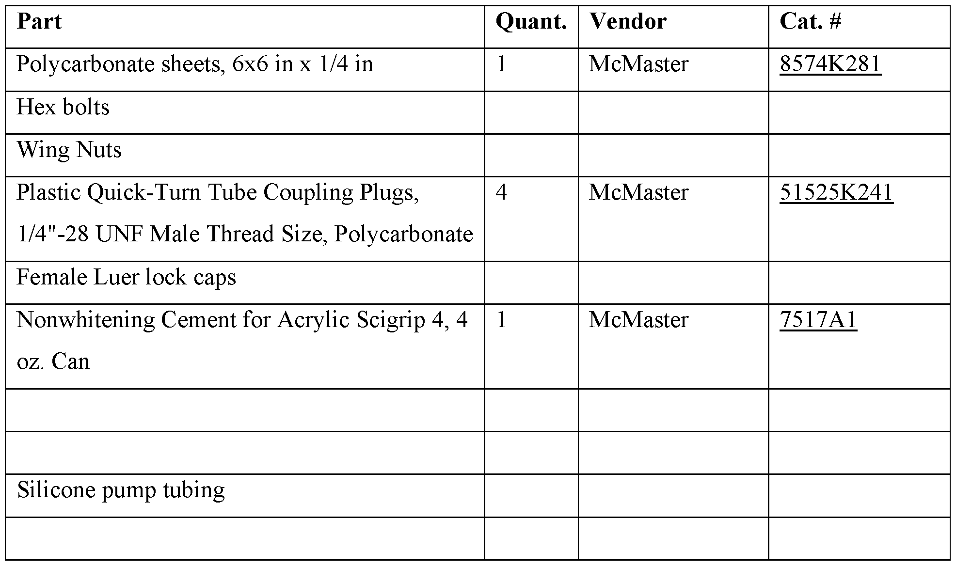
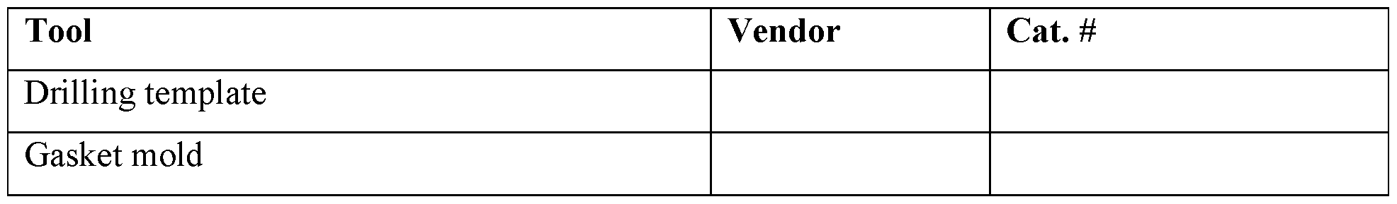
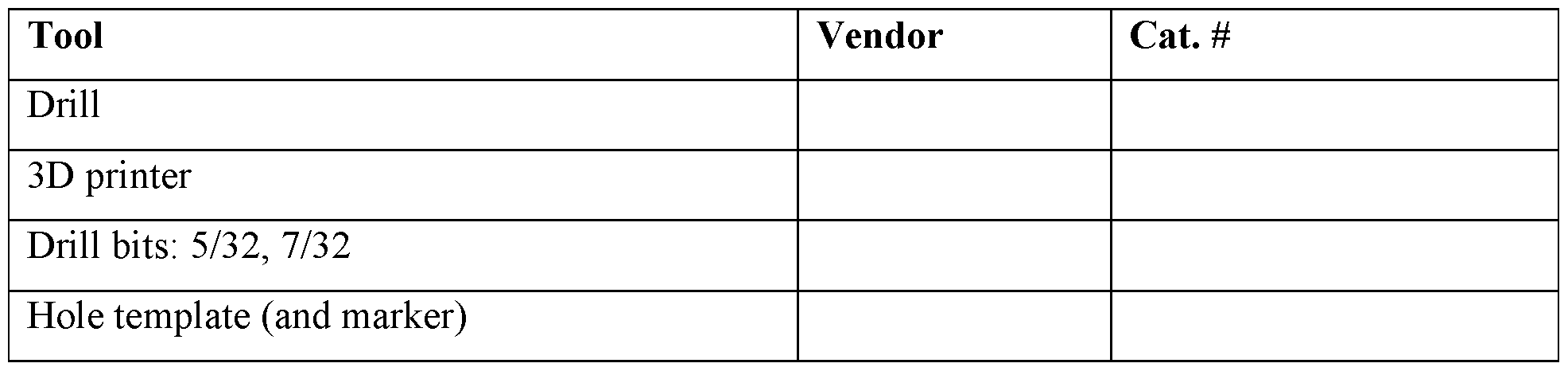
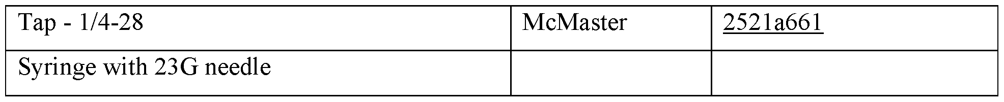
Table 14c. Tools
Polycarbonate Plates:
1. Cut ¼” plates to 3”x3”
2. Use the hole template to mark the location of drill holes, then drill.
a. 5/32” holes for hex bolts
b. 7/32” holes for tapped holes
3. Tap the four appropriate holes with ¼-28 taps.
a. Tap should extend will through to ensure sufficient tapping.
4. Screw in the threaded Luer lock connectors, then unscrew each 1 full turn
5. Apply acrylic cement to the point where the threaded connectors meet the
polycarbonate, then turn to tighten.
a. Apply the solvent carefully to avoid dripping!
6. Apply a bit more solvent cement to the seam and allow it to evaporate
7. Flip the lid over and apply solvent cement to the interior seam, allowing it to
evaporate.
Figure 10 depicts the plate design.
Spacing ring:
1. Print the spaceing ring
Gasket
1. Print the gasket molds
2. Mix 18 mL of elastomer base with 2 mL of hardener.
3. Mix thoroughly with a spatula.
a. Thorough mixing is critical. Beat the solution until bubbles occlude the entire volume. Alternate between stirring, beating, and spinning the spatula to mix on all scales. Pay special attention to the bottom tip of the conical, in which mixing is especially difficult.
4. Degass by applying a vacuum using a steriflip tube.
a. Degassing will take ~30 minutes.
Casting the PDMS Gasket
1. To a 50 mL conical tube, add 18 mL of Silicone elastomer base
The silicone elastomer is highly viscous. Use a 50 mL serological pipet and be patient.
2. Add 2 mL of catalyst
3. Mix vigorously for five minutes with a spatula.
Alternate between twirling a spatula within an immobilized tube, scooping, and mixing. The mixture should be cloudy with bubbles throughout.
4. Degas the mixture thoroughly.
Attach a steriflip tube to degas. Degassing takes approximately 30 minutes.
5. Pour the silicone solution into the gasket mold
The various methods and techniques described above provide a number of ways to carry out the invention. Of course, it is to be understood that not necessarily all objectives or advantages described may be achieved in accordance with any particular embodiment described herein. Thus, for example, those skilled in the art will recognize that the methods can be performed in a manner that achieves or optimizes one advantage or group of advantages as taught herein without necessarily achieving other objectives or advantages as may be taught or suggested herein. A variety of advantageous and disadvantageous alternatives are mentioned herein. It is to be understood that some preferred embodiments specifically include one, another, or several advantageous features, while others specifically exclude one, another, or several disadvantageous features, while still others specifically mitigate a present disadvantageous feature by inclusion of one, another, or several advantageous features.
Furthermore, the skilled artisan will recognize the applicability of various features from different embodiments. Similarly, the various elements, features and steps discussed above, as well as other known equivalents for each such element, feature or step, can be mixed and matched by one of ordinary skill in this art to perform methods in accordance with principles described herein. Among the various elements, features, and steps some will be specifically included and others specifically excluded in diverse embodiments.
Although the invention has been disclosed in the context of certain embodiments and examples, it will be understood by those skilled in the art that the embodiments of the invention extend beyond the specifically disclosed embodiments to other alternative embodiments and/or uses and modifications and equivalents thereof.
Many variations and alternative elements have been disclosed in embodiments of the present invention. Still further variations and alternate elements will be apparent to one of skill in the art. Among these variations, without limitation, are the compositions and methods related to expansion of stem cells, including bioprinting designs and techniques for printing using bioprinting, bioink constituents, and the particular use of the products created through the teachings of the invention. Various embodiments of the invention can specifically include or exclude any of these variations or elements.
In some embodiments, the numbers expressing quantities of ingredients, properties such as concentration, reaction conditions, and so forth, used to describe and claim certain embodiments of the invention are to be understood as being modified in some instances by the term“about.” Accordingly, in some embodiments, the numerical parameters set forth in the written description and attached claims are approximations that can vary depending upon the desired properties sought to be obtained by a particular embodiment. In some embodiments, the numerical parameters should be construed in light of the number of reported significant digits and by applying ordinary rounding techniques. Notwithstanding that the numerical ranges and parameters setting forth the broad scope of some embodiments of the invention are approximations, the numerical values set forth in the specific examples are reported as precisely as practicable. The numerical values presented in some embodiments of the invention may contain certain errors necessarily resulting from the standard deviation found in their respective testing measurements.
In some embodiments, the terms“a” and“an” and“the” and similar references used in the context of describing a particular embodiment of the invention (especially in the context of certain of the following claims) can be construed to cover both the singular and the plural. The recitation of ranges of values herein is merely intended to serve as a shorthand method of referring individually to each separate value falling within the range. Unless otherwise indicated herein, each individual value is incorporated into the specification as if it were individually recited herein. All methods described herein can be performed in any suitable order unless otherwise indicated herein or otherwise clearly contradicted by context. The use of any and all examples, or exemplary language (e.g.“such as”) provided with respect to certain embodiments herein is intended merely to better illuminate the invention and does not pose a limitation on the scope of the invention otherwise claimed. No language in the specification should be construed as indicating any non-claimed element essential to the practice of the invention.
Groupings of alternative elements or embodiments of the invention disclosed herein are not to be construed as limitations. Each group member can be referred to and claimed individually or in any combination with other members of the group or other elements found herein. One or more members of a group can be included in, or deleted from, a group for reasons of convenience and/or patentability. When any such inclusion or deletion occurs, the specification is herein deemed to contain the group as modified thus fulfilling the written description of all Markush groups used in the appended claims.
Preferred embodiments of this invention are described herein, including the best mode known to the inventor for carrying out the invention. Variations on those preferred embodiments will become apparent to those of ordinary skill in the art upon reading the foregoing description. It is contemplated that skilled artisans can employ such variations as appropriate, and the invention can be practiced otherwise than specifically described herein. Accordingly, many embodiments of this invention include all modifications and equivalents of the subject matter recited in the claims appended hereto as permitted by applicable law. Moreover, any combination of the above-described elements in all possible variations thereof is encompassed by the invention unless otherwise indicated herein or otherwise clearly contradicted by context.
Furthermore, numerous references have been made to patents and printed publications throughout this specification. Each of the above cited references and printed publications are herein individually incorporated by reference in their entirety.
In closing, it is to be understood that the embodiments of the invention disclosed herein are illustrative of the principles of the present invention. Other modifications that can be employed can be within the scope of the invention. Thus, by way of example, but not of limitation, alternative configurations of the present invention can be utilized in accordance with the teachings herein. Accordingly, embodiments of the present invention are not limited to that precisely as shown and described.
Claims
1. A bioprinter for dispensing at least one biomaterial, comprising:
a processor configured to determine a path;
a support assembly, comprising one or more linear rods;
a gantry comprising:
at least one extruder, each extruder comprising a nozzle and a tube,
a plunger,
a threaded shaft,
a stepper motor,
wherein the processor is operatively coupled to the support assembly to move the one or more linear rods along a determined path, and operatively coupled to the stepper motor, wherein the one or more linear rods are attached to the gantry,
wherein the plunger is inside the tube and comprises a means for attachment to the threaded shaft,
wherein the threaded shaft is mechanically coupled to the stepper motor,
wherein the nozzle is at one end of the tube.
2. The bioprinter of claim I, wherein the means for attachment to the threaded comprises reciprocating members on each of the plunger and threaded shaft.
3. The bioprinter of claim 2, wherein the reciprocating members are a snap fit coupling.
4. The bioprinter of claim 1, wherein the bioprinter comprises two extruders.
5. The bioprinter of claim 1, wherein the plunger is configured to exert pressure through the nozzle.
6. A bioprinted assembly made by the bioprinter of claim 1.
7. The bioprinted assembly of claim 6, comprising vascular cells in an organized fashion deposited on a substrate.
8. 'The bioprinted assembly of claim 7, comprising one or more non-vascular cells.
9. A bioprinted assembly, comprising:
a layer of vascular cells in an organized fashion deposited on a substrate.
10. The bioprinted assembly of claim 9, comprising induced endothelial cells (iECs).
11. The bioprinted assembly of claim 9, comprising one or more non- vascular ceils.
12. The bioprinted assembly of claim 11, wherein the non-vaseular cells are derived from induced pluripoteni stem cells (iPSCs).
13. A bioink, comprising:
a quantity of at least one cell type suspended in a substrate suitable for bioprinting.
14. The bioink of claim 13, comprising induced pluripoteni stem cell endothelial cells (iECs).
15. The bioink of claim 13, comprising one or more non-vascular cells.
16. The bioink of claim 15, wherein the non -vascular cells are derived from induced pluripoteni stem cells (iPSCs).
17. The bioink of claim 13, wherein the substrate comprises one or more of cell culture media, gelatin and fibrinogen.
Priority Applications (1)
| Application Number | Priority Date | Filing Date | Title |
|---|---|---|---|
| US17/254,783 US12305196B2 (en) | 2018-06-28 | 2019-06-26 | Compact mechanical syringe extruder for 3D bioprinting of cell laden gels |
Applications Claiming Priority (2)
| Application Number | Priority Date | Filing Date | Title |
|---|---|---|---|
| US201862691492P | 2018-06-28 | 2018-06-28 | |
| US62/691,492 | 2018-06-28 |
Publications (1)
| Publication Number | Publication Date |
|---|---|
| WO2020006096A1 true WO2020006096A1 (en) | 2020-01-02 |
Family
ID=68987292
Family Applications (1)
| Application Number | Title | Priority Date | Filing Date |
|---|---|---|---|
| PCT/US2019/039277 Ceased WO2020006096A1 (en) | 2018-06-28 | 2019-06-26 | Compact mechanical syringe extruder for 3d bioprinting of cell laden gels |
Country Status (2)
| Country | Link |
|---|---|
| US (1) | US12305196B2 (en) |
| WO (1) | WO2020006096A1 (en) |
Cited By (1)
| Publication number | Priority date | Publication date | Assignee | Title |
|---|---|---|---|---|
| US12305196B2 (en) | 2018-06-28 | 2025-05-20 | Cedars-Sinai Medical Center | Compact mechanical syringe extruder for 3D bioprinting of cell laden gels |
Families Citing this family (2)
| Publication number | Priority date | Publication date | Assignee | Title |
|---|---|---|---|---|
| NL2021381B1 (en) * | 2018-07-24 | 2020-01-30 | Ultimaker Bv | Method and apparatus for managing ooze from a print nozzle |
| US20230264418A1 (en) * | 2022-02-18 | 2023-08-24 | Dharneedar Ravichandran | Multiphase direct ink writing for multilayered composites |
Citations (3)
| Publication number | Priority date | Publication date | Assignee | Title |
|---|---|---|---|---|
| WO2017040975A1 (en) * | 2015-09-04 | 2017-03-09 | The General Hospital Corporation | Three dimensional microtissue bioprinter |
| US20170369827A1 (en) * | 2016-07-12 | 2017-12-28 | Deka Products Limited Partnership | System and Method for Printing Tissue |
| WO2018089515A1 (en) * | 2016-11-09 | 2018-05-17 | The United States Of America, As Represented By The Secretary, Department Of Health And Human Services | 3d vascularized human ocular tissue for cell therapy and drug discovery |
Family Cites Families (4)
| Publication number | Priority date | Publication date | Assignee | Title |
|---|---|---|---|---|
| US2498672A (en) | 1947-05-26 | 1950-02-28 | Antonina S Glass | Motor drive for medical syringes |
| US6645177B1 (en) * | 1999-02-09 | 2003-11-11 | Alaris Medical Systems, Inc. | Directly engaged syringe driver system |
| WO2014176697A1 (en) * | 2013-04-30 | 2014-11-06 | Chen haotian | Microfluidic devices and methods for the extrusion of tubular structures |
| WO2020006096A1 (en) | 2018-06-28 | 2020-01-02 | Cedars-Sinai Medical Center | Compact mechanical syringe extruder for 3d bioprinting of cell laden gels |
-
2019
- 2019-06-26 WO PCT/US2019/039277 patent/WO2020006096A1/en not_active Ceased
- 2019-06-26 US US17/254,783 patent/US12305196B2/en active Active
Patent Citations (3)
| Publication number | Priority date | Publication date | Assignee | Title |
|---|---|---|---|---|
| WO2017040975A1 (en) * | 2015-09-04 | 2017-03-09 | The General Hospital Corporation | Three dimensional microtissue bioprinter |
| US20170369827A1 (en) * | 2016-07-12 | 2017-12-28 | Deka Products Limited Partnership | System and Method for Printing Tissue |
| WO2018089515A1 (en) * | 2016-11-09 | 2018-05-17 | The United States Of America, As Represented By The Secretary, Department Of Health And Human Services | 3d vascularized human ocular tissue for cell therapy and drug discovery |
Cited By (1)
| Publication number | Priority date | Publication date | Assignee | Title |
|---|---|---|---|---|
| US12305196B2 (en) | 2018-06-28 | 2025-05-20 | Cedars-Sinai Medical Center | Compact mechanical syringe extruder for 3D bioprinting of cell laden gels |
Also Published As
| Publication number | Publication date |
|---|---|
| US20210269776A1 (en) | 2021-09-02 |
| US12305196B2 (en) | 2025-05-20 |
Similar Documents
| Publication | Publication Date | Title |
|---|---|---|
| US11577451B2 (en) | Bioprinter for the fabrication of tissue | |
| Duarte Campos et al. | Bioprinting cell-and spheroid-laden protein-engineered hydrogels as tissue-on-chip platforms | |
| US20210008788A1 (en) | Automated devices, systems, and methods for the fabrication of tissue | |
| WO2020006096A1 (en) | Compact mechanical syringe extruder for 3d bioprinting of cell laden gels | |
| JP2016526910A5 (en) | ||
| CN103608451A (en) | Culture Methods, Mature Adipocyte Populations, and Drug Screening Methods | |
| Coffin et al. | FRESH 3D bioprinting a ventricle-like cardiac construct using human stem cell-derived cardiomyocytes | |
| TWI821230B (en) | Cell culture device, culture medium aspirator and cell culture method | |
| US20250250525A1 (en) | Cell culture vessel and cell culture device | |
| AU2015202836B2 (en) | Devices, systems, and methods for the fabrication of tissue | |
| KR20190140949A (en) | Vascularized In Vitro Arrangement of Living Cells | |
| AU2016253591B2 (en) | Devices, systems, and methods for the fabrication of tissue | |
| HK40056621B (en) | Application of cell culturing apparatus | |
| Macown | Microfabricated Devices for Adherent Stem Cell Culture | |
| HK1187024B (en) | Devices, systems, and methods for the fabrication of tissue | |
| HK1187024A (en) | Devices, systems, and methods for the fabrication of tissue |
Legal Events
| Date | Code | Title | Description |
|---|---|---|---|
| 121 | Ep: the epo has been informed by wipo that ep was designated in this application |
Ref document number: 19825039 Country of ref document: EP Kind code of ref document: A1 |
|
| NENP | Non-entry into the national phase |
Ref country code: DE |
|
| 122 | Ep: pct application non-entry in european phase |
Ref document number: 19825039 Country of ref document: EP Kind code of ref document: A1 |
|
| WWG | Wipo information: grant in national office |
Ref document number: 17254783 Country of ref document: US |