US11253757B2 - Golf club head - Google Patents
Golf club head Download PDFInfo
- Publication number
- US11253757B2 US11253757B2 US17/090,113 US202017090113A US11253757B2 US 11253757 B2 US11253757 B2 US 11253757B2 US 202017090113 A US202017090113 A US 202017090113A US 11253757 B2 US11253757 B2 US 11253757B2
- Authority
- US
- United States
- Prior art keywords
- crown
- thick part
- sole
- golf club
- club head
- Prior art date
- Legal status (The legal status is an assumption and is not a legal conclusion. Google has not performed a legal analysis and makes no representation as to the accuracy of the status listed.)
- Active
Links
Images


Classifications
-
- A—HUMAN NECESSITIES
- A63—SPORTS; GAMES; AMUSEMENTS
- A63B—APPARATUS FOR PHYSICAL TRAINING, GYMNASTICS, SWIMMING, CLIMBING, OR FENCING; BALL GAMES; TRAINING EQUIPMENT
- A63B53/00—Golf clubs
- A63B53/04—Heads
- A63B53/0466—Heads wood-type
-
- A—HUMAN NECESSITIES
- A63—SPORTS; GAMES; AMUSEMENTS
- A63B—APPARATUS FOR PHYSICAL TRAINING, GYMNASTICS, SWIMMING, CLIMBING, OR FENCING; BALL GAMES; TRAINING EQUIPMENT
- A63B53/00—Golf clubs
- A63B53/04—Heads
- A63B53/0408—Heads characterised by specific dimensions, e.g. thickness
-
- A—HUMAN NECESSITIES
- A63—SPORTS; GAMES; AMUSEMENTS
- A63B—APPARATUS FOR PHYSICAL TRAINING, GYMNASTICS, SWIMMING, CLIMBING, OR FENCING; BALL GAMES; TRAINING EQUIPMENT
- A63B53/00—Golf clubs
- A63B53/04—Heads
- A63B53/0408—Heads characterised by specific dimensions, e.g. thickness
- A63B53/0412—Volume
-
- A—HUMAN NECESSITIES
- A63—SPORTS; GAMES; AMUSEMENTS
- A63B—APPARATUS FOR PHYSICAL TRAINING, GYMNASTICS, SWIMMING, CLIMBING, OR FENCING; BALL GAMES; TRAINING EQUIPMENT
- A63B53/00—Golf clubs
- A63B53/04—Heads
- A63B53/0433—Heads with special sole configurations
-
- A—HUMAN NECESSITIES
- A63—SPORTS; GAMES; AMUSEMENTS
- A63B—APPARATUS FOR PHYSICAL TRAINING, GYMNASTICS, SWIMMING, CLIMBING, OR FENCING; BALL GAMES; TRAINING EQUIPMENT
- A63B53/00—Golf clubs
- A63B53/04—Heads
- A63B53/0437—Heads with special crown configurations
-
- A—HUMAN NECESSITIES
- A63—SPORTS; GAMES; AMUSEMENTS
- A63B—APPARATUS FOR PHYSICAL TRAINING, GYMNASTICS, SWIMMING, CLIMBING, OR FENCING; BALL GAMES; TRAINING EQUIPMENT
- A63B60/00—Details or accessories of golf clubs, bats, rackets or the like
- A63B60/02—Ballast means for adjusting the centre of mass
-
- A—HUMAN NECESSITIES
- A63—SPORTS; GAMES; AMUSEMENTS
- A63B—APPARATUS FOR PHYSICAL TRAINING, GYMNASTICS, SWIMMING, CLIMBING, OR FENCING; BALL GAMES; TRAINING EQUIPMENT
- A63B53/00—Golf clubs
- A63B53/04—Heads
- A63B2053/0491—Heads with added weights, e.g. changeable, replaceable
-
- A—HUMAN NECESSITIES
- A63—SPORTS; GAMES; AMUSEMENTS
- A63B—APPARATUS FOR PHYSICAL TRAINING, GYMNASTICS, SWIMMING, CLIMBING, OR FENCING; BALL GAMES; TRAINING EQUIPMENT
- A63B53/00—Golf clubs
- A63B53/04—Heads
- A63B53/0416—Heads having an impact surface provided by a face insert
Definitions
- the present invention relates to golf club heads.
- a golf club head includes a hollow structure defined by a face, a crown, a sole, and a back.
- the crown includes a crown thick part on the back side
- the sole includes a sole thick part on the back side.
- the back includes a back end thinner than the thickest portion of each of the crown thick part and the sole thick part.
- the crown thick part and the sole thick part are separated by the back including the back end.
- the crown thick part and the sole thick part lie over and cover at least part of each other to form an overlap part extending in a toe-heel direction in a view in a crown-sole direction.
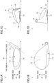
- FIGS. 1A through 1D are diagrams illustrating a golf club head according to an embodiment
- FIG. 2 is a cross-sectional view of the golf club head, taken along a vertical plane extending in a face-back direction;
- FIG. 3 is a plan view of the golf club head, looking at the golf club head from the crown side in a crown-sole direction;
- FIG. 4 is a plan view of the golf club head, looking at the golf club head from the crown side in the crown-sole direction;
- FIG. 5 is a plan view of the golf club head, looking at the golf club head from the crown side in the crown-sole direction;
- FIG. 6 is a cross-sectional view of another golf club head according to the embodiment, taken along a vertical plane extending in a face-back direction;
- FIG. 7 is a cross-sectional view of yet another golf club head according to the embodiment, taken along a vertical plane extending in a face-back direction;
- FIG. 8 is a cross-sectional view of still another golf club head according to the embodiment, taken along a vertical plane extending in a face-back direction.
- FIGS. 1A, 1B, 1C, and 1D are a front view, a plan view, a left side view, and a right side view, respectively, of a golf club head 1 according to the embodiment.
- FIG. 1A The front elevational view of FIG. 1A is a view taken from the side of a face surface 11 f of the golf club head 1 (that is, a view looking at the face surface 11 f ), depicting the golf club head 1 resting (soled) on a horizontal plane H (corresponding to a ground surface) at a standard lie angle ⁇ and a standard loft angle (not depicted).
- the central axis of the bore of a hosel 15 is indicated by the dashed line J.
- the double-headed arrow d 1 indicates the “toe-heel” (left-right) direction, namely, the direction from the toe side to the heel side or the direction from the heel side to the toe side, of the golf club head 1
- the double-headed arrow d 2 indicates the “crown-sole” (up-down) direction, namely, the direction from the crown side to the sole side or the direction from the sole side to the crown side, of the golf club head 1
- the double-headed arrow d 3 indicates the “face-back” (front-rear) direction, namely, the direction from the face side to the back side or the direction from the back side to the face side, of the golf club head 1 .
- the golf club head 1 depicted in FIGS. 1A through 1D is a wood-type golf club head such as a hybrid or fairway wood club head, but may also be a driver club head.
- the golf club head 1 may be made using, for example, titanium, a titanium alloy, stainless steel, aluminum, an aluminum alloy, a ferrous metal, magnesium, a magnesium alloy, a fiber reinforced resin, or the like.
- the golf club head 1 is manufactured by, for example, casting. The golf club head 1 is described in more detail below.
- the golf club head 1 is a hollow structure that includes a face 11 , a crown 12 , a sole 13 , a back 14 , and the hosel 15 .
- An internal surface and an eternal surface of the hollow structure of the golf club head 1 may be referred to as “internal surface” and “external surface,” respectively, of the golf club head 1 .
- the face 11 defines a front portion of the golf club head 1 , and includes the face surface 11 f , which defines a ball-striking surface between the crown 12 and the sole 13 in the crown-sole direction.
- the face 11 has a predetermined thickness.
- the face surface 11 f forms an external surface of the face 11 .
- the crown 12 defines a top portion of the golf club head 1 .
- the sole 13 defines a bottom portion of the golf club head 1 .
- the back 14 extends between the crown 12 and the sole 13 on the opposite side from the face 11 , to define a curved periphery of the golf club head 1 that is continuous with the face surface 11 f .
- the hosel 15 receives a shaft.
- An attachment part (weight port) configured to receive a head weight adjustment component (weight) may be provided in the sole 13 .
- weight port configured to receive a head weight adjustment component (weight)
- Weight adjustment using a weight makes it possible to adjust the position of the center of gravity of the golf club head 1 .
- FIG. 2 is a cross-sectional view of the golf club head 1 , taken along a vertical plane extending in the face-back direction.
- FIGS. 3 through 5 are plan views of the golf club head 1 , looking at the golf club head 1 from the crown side in the crown-sole direction.
- FIG. 3 illustrates the position of a crown thick part 121 in a plan view of the golf club head 1 .
- FIG. 4 illustrates the position of a sole thick part 131 in a plan view of the golf club head 1 .
- FIG. 5 illustrates the position of an overlap part 20 that is an overlap between the crown thick part 121 and the sole thick part 131 in a plan view of the golf club head 1 .
- the crown 12 includes the crown thick part 121 in the internal surface on the back side.
- the crown thick part 121 has a curved strip shape extending in the toe-heel direction along the back-side contour shape of the crown 12 .
- the dashed line contacting the crown thick part 121 indicates where the internal surface of the golf club head 1 would be without the crown thick part 121 .
- the internal surface of the golf club head 1 protrudes inward to form the crown thick part 121 , which is thicker than other parts of the crown 12 , so that the crown thick part 121 forms a one-piece structure with other parts of the golf club head 1 .
- the thickness of the wall of the golf club head 1 namely, the thickness of the golf club head 1 between its external surface and the dashed line in FIG. 2 , is equal to the average thickness of the wall of the golf club head 1 in a portion of the crown 12 where the crown thick part 121 is not formed.
- a thickness T 1 of the thickest portion of the crown thick part 121 is, for example, 1.0 mm or more and 6.0 mm or less.
- the thickest portion of the crown thick part 121 is where the crown thick part 121 is thickest when the thickness is measured from the external surface of the golf club head 1 in a direction in which a normal to the external surface extends at each point.
- the sole 13 includes the sole thick part 131 in the internal surface on the back side.
- the sole thick part 131 has a substantially semicircular shape and provided in a region of the sole 13 other than its face side part.
- the dashed line contacting the sole thick part 131 indicates where the internal surface of the golf club head 1 would be without the sole thick part 131 .
- the internal surface of the golf club head 1 protrudes inward to form the sole thick part 131 , which is thicker than other parts of the sole 13 , so that the sole thick part 131 forms a one-piece structure with other parts of the golf club head 1 .
- the thickness of the wall of the golf club head 1 namely, the thickness of the golf club head 1 between its external surface and the dashed line in FIG. 2 , is equal to the average thickness of the wall of the golf club head 1 in a portion of the sole 13 where the sole thick part 131 is not formed.
- a thickness T 2 of the thickest portion of the sole thick part 131 is, for example, 0.5 mm or more and 8.0 mm or less.
- the thickest portion of the sole thick part 131 is where the sole thick part 131 is thickest when the thickness is measured from the external surface of the golf club head 1 in a direction in which a normal to the external surface extends at each point.
- the back 14 includes a back end 141 which is thinner than the thickest portion of each of the crown thick part 121 and the sole thick part 131 .
- the crown thick part 121 and the sole thick part 131 are spaced apart across the back 14 including the back end 141 .
- the weight of the crown thick part 121 is, for example, 1 g or more and 44 g or less.
- the weight of the sole thick part 131 is, for example, 5 g or more and 70 g or less.
- the ratio of the weight of the crown thick part 121 to the weight of the sole thick part 131 is preferably 5% or more and 65% or less.
- the ratio of the weight of the crown thick part 121 to the weight of the entirety of the golf club head 1 is preferably 0.4% or more and 20% or less. These ratios produce the effect of getting a ball to fly on a high trajectory to stop on the green.
- the weight of the entirety of the golf club head 1 is, for example, 220 g or more and 270 g or less.
- the crown thick part 121 and the sole thick part 131 lie over and cover at least part of each other to form the overlap part 20 elongated in the toe-heel direction.
- the overlap part 20 has a curved strip shape extending in the toe-heel direction along the back-side contour shape of the crown 12 .
- 70% or more, more preferably, 80% or more, and still more preferably, 90% or more of the crown thick part 121 overlaps the sole thick part 131 .
- the entirety of the crown thick part 121 may lie over or be covered with the sole thick part 131 to form the overlap part 20 when viewed in the crown-sole direction.
- the overlap between the crown thick part 121 and the sole thick part 131 becomes larger, it becomes easier to adjust the position of the center of gravity in the height (up-down) direction without changing the position of the center of gravity in the front-rear direction or the left-right direction.
- the overlap part 20 may also have a substantially rectilinear strip shape extending in the toe-heel direction.
- the curved strip shape is more preferable because it allows a wider weight adjustable range.
- a toe-side end 21 of the overlap part 20 is a position where a line segment L 1 passing through a center of gravity G of the golf club head 1 contacts the overlap part 20 on the toe side in a plan view.
- a heel-side end 22 of the overlap part 20 is a position where a line segment L 2 passing through the center of gravity G contacts the overlap part 20 on the heel side in a plan view. That is, in a plan view, the overlap part 20 is within an area on the back side of the line segments L 1 and L 2 .
- the overlap part 20 lies on the toe side and on the heel side relative to the center of gravity G.
- the face-back direction be the 6 o'clock-12 o'clock direction with the center of gravity G being at the center (according to an imaginary clock dial or on an imaginary horizontal clock face) in a plan view
- the toe-side end 21 is positioned on the 12 o'clock side of 9 o'clock
- the heel-side end 22 is positioned on the 12 o'clock side of 3 o'clock.
- the toe-side end 21 is positioned between 9 o'clock and 12 o'clock and the heel-side end 22 is positioned between 3 o'clock and 12 o'clock.
- This placement makes it possible to produce the effect of increasing the moment of inertia (MOI) (the MOI increasing effect).
- MOI moment of inertia
- the toe-side end 21 is positioned between 9 o'clock and 12 o'clock and the heel-side end 22 is positioned between 2 o'clock and 12 o'clock. This placement makes the MOI increasing effect more prominent.
- the crown 12 has the crown thick part 121 on the back side
- the sole 13 has the sole thick part 131 on the back side
- the back 14 has the back end 141 thinner than the thickest portion of each of the crown thick part 121 and the sole thick part 131 .
- the crown thick part 121 and the sole thick part 131 are separated by the back 14 including the back end 141 , and when viewed in the crown-sole direction (in a plan view), the crown thick part 121 and the sole thick part 131 at least overlap each other to form the overlap part 20 extending in the toe-heel direction.
- This structure vertically separates the crown thick part 121 and the sole thick part 131 . Therefore, it is possible to increase freedom in designing the position of the center of gravity of the golf club head 1 . Furthermore, the crown thick part 121 is spaced apart from the sole thick part 131 . This facilitates such designing as to prevent the center of gravity of the golf club head 1 from being too low. Furthermore, the presence of the overlap part 20 facilitates adjustment of the position of the center of gravity in the height (up-down) direction without changing the position of the center of gravity in the front-rear direction or the left-right direction.
- a first variation of the embodiment illustrates an example of a golf club head whose face or crown includes a separate member.
- a description of the same elements as those of the above-described embodiment may be omitted.
- FIG. 6 is a cross-sectional view of a golf club head 1 A, taken along a vertical plane extending in the face-back direction.
- the golf club head 1 A is different from the golf club head 1 (see, for example, FIGS. 1A through 1D and 2 ) in that an opening 12 x is provided in part of the crown 12 and that a crown member 30 is joined to the crown 12 at the opening 12 x.
- steps that fit to each other to be positioned are provided one in each of an inner wall surface (opening edge) of the crown 12 defining the opening 12 x and a sidewall surface (peripheral surface) of the crown member 30 .
- the crown member 30 is joined to the crown 12 within the opening 12 x to close the opening 12 x , and defines a top portion of the golf club head 1 A together with the crown 12 .
- the crown thick part 121 and the sole thick part 131 are positioned in the body of the golf club head 1 in which the opening 12 x is provided.
- Suitable materials for the crown member 30 include, for example, metal materials, non-metal materials, and materials lower in specific gravity than metal materials.
- specific materials for the crown member 30 include titanium, a titanium alloy, stainless steel, aluminum, an aluminum alloy, a ferrous metal, magnesium, a magnesium alloy, and a fiber reinforced resin.
- the crown member 30 is joined to the crown 12 by, for example, welding or bonding in such a manner as to close the opening 12 x .
- one or more of processes such as painting, polishing, and machining may be performed on an as-needed basis.
- FIG. 7 is a cross-sectional view of a golf club head 1 B, taken along a vertical plane extending in the face-back direction.
- the golf club head 1 B is different from the golf club head 1 (see, for example, FIGS. 1A through 1D and 2 ) in that an opening 11 x is provided in a face and that a face member 31 is joined to the face at the opening 11 x.
- steps that fit to each other to be positioned are provided one in each of an inner wall surface (opening edge) of the face defining the opening 11 x and a sidewall surface (peripheral surface) of the face member 31 .
- the face member 31 is joined to the face within the opening 11 x to close the opening 11 x , and defines the face including a face surface 31 f .
- the crown thick part 121 and the sole thick part 131 are positioned in the body of the golf club head 1 in which the opening 11 x is provided.
- Suitable materials for the face member 31 include, for example, metal materials, non-metal materials, and materials lower in specific gravity than metal materials.
- specific materials for the face member 31 include titanium, a titanium alloy, stainless steel, aluminum, an aluminum alloy, a ferrous metal, magnesium, a magnesium alloy, and a fiber reinforced resin.
- the face member 31 is joined to the face by, for example, welding or bonding in such a manner as to close the opening 11 x .
- one or more of processes such as painting, polishing, and machining may be performed on an as-needed basis.
- multiple components may be joined to be assembled into a golf club head. This facilitates removal of a core in a mold when manufacturing the body of the golf club head in which the crown thick part 121 and the sole thick part 131 are provided by casting.
- crown member 30 as a separate member as in the golf club head 1 A makes it possible to select the material and the thickness of the crown member 30 and therefore to further increase freedom in designing the center of gravity in a vertical direction.
- the face member 31 as a separate member as in the golf club head 1 B makes it possible to select a material higher in strength than the body of the golf club head 1 as the face member 31 and therefore to increase the repulsive force of the face member 31 at impact.
- a second variation of the embodiment illustrates an example of a golf club head in which a crown thick part is provided as a separate member.
- a description of the same elements as those of the above-described embodiment may be omitted.
- FIG. 8 is a cross-sectional view of a golf club head 1 C, taken along a vertical plane extending in the face-back direction.
- the golf club head 1 C is different from the golf club head 1 (see, for example, FIGS. 1A through 1D and 2 ) in that a crown thick part 122 is a member separate from the crown 12 .
- the external surface of the crown 12 on the back side is depressed inward (namely, toward the internal space of the golf club head 1 C) to form a depression 12 y , in which the crown thick part 122 is placed.
- the crown thick part 122 is formed of a material higher in specific gravity than the crown 12 . Examples of such a material include tungsten nickel (W—Ni), a copper alloy, and a lead alloy.
- the crown thick part 122 is joined to the crown 12 by, for example, welding, bonding, brazing, bucking or the like in such a manner as to fill in the depression 12 y .
- one or more of processes such as painting, polishing, and machining may be performed on an as-needed basis.
- the crown thick part 122 is a member separate from the crown 12 . This makes it possible to select a material higher in specific gravity than the crown 12 as the material of the crown thick part 122 and therefore to further increase freedom in designing the position of the center of gravity of the golf club head 1 C.
Landscapes
- Health & Medical Sciences (AREA)
- General Health & Medical Sciences (AREA)
- Physical Education & Sports Medicine (AREA)
- Life Sciences & Earth Sciences (AREA)
- Engineering & Computer Science (AREA)
- Wood Science & Technology (AREA)
- Golf Clubs (AREA)
Abstract
Description
Claims (11)
Applications Claiming Priority (3)
| Application Number | Priority Date | Filing Date | Title |
|---|---|---|---|
| JPJP2019-230304 | 2019-12-20 | ||
| JP2019230304A JP7437150B2 (en) | 2019-12-20 | 2019-12-20 | golf club head |
| JP2019-230304 | 2019-12-20 |
Publications (2)
| Publication Number | Publication Date |
|---|---|
| US20210187367A1 US20210187367A1 (en) | 2021-06-24 |
| US11253757B2 true US11253757B2 (en) | 2022-02-22 |
Family
ID=76437830
Family Applications (1)
| Application Number | Title | Priority Date | Filing Date |
|---|---|---|---|
| US17/090,113 Active US11253757B2 (en) | 2019-12-20 | 2020-11-05 | Golf club head |
Country Status (2)
| Country | Link |
|---|---|
| US (1) | US11253757B2 (en) |
| JP (1) | JP7437150B2 (en) |
Citations (27)
| Publication number | Priority date | Publication date | Assignee | Title |
|---|---|---|---|---|
| US5272802A (en) * | 1992-01-21 | 1993-12-28 | Head Sports, Inc. | Method for construction of a golf club |
| US5316298A (en) * | 1992-04-14 | 1994-05-31 | Skis Rossignol S.A. | Golf club head having vibration damping means |
| US5624331A (en) * | 1995-10-30 | 1997-04-29 | Pro-Kennex, Inc. | Composite-metal golf club head |
| US5755624A (en) * | 1996-01-22 | 1998-05-26 | Callaway Golf Company | Selectively balanced golf club heads and method of head selection |
| US20020123394A1 (en) * | 2001-03-05 | 2002-09-05 | Masaei Tsurumaki | Golf club and manufacturing method thereof |
| US20050049081A1 (en) * | 2003-08-26 | 2005-03-03 | Boone David D. | Golf club head having internal fins for resisting structural deformation and mechanical shockwave migration |
| US6929565B2 (en) * | 2001-10-24 | 2005-08-16 | The Yokohama Rubber Co., Ltd. | Golf club head |
| US6945877B2 (en) * | 2003-02-24 | 2005-09-20 | K.K.Endo Seisakusho | Golf club |
| US7377861B2 (en) * | 2005-08-23 | 2008-05-27 | Bridgestone Sports Co., Ltd. | Golf club head |
| US7431668B2 (en) * | 2005-08-23 | 2008-10-07 | Bridgestone Sports Co., Ltd. | Golf club head |
| US7445564B2 (en) * | 2004-03-30 | 2008-11-04 | Daiwa Seiko, Inc. | Golf club head |
| US7455597B2 (en) * | 2005-12-02 | 2008-11-25 | Bridgestone Sports Co., Ltd. | Golf club head |
| US7658687B2 (en) | 2006-09-28 | 2010-02-09 | Sri Sports Limited | Wood-type golf club head |
| US7753807B2 (en) * | 2006-12-19 | 2010-07-13 | Sri Sports Limited | Golf club head |
| US7775906B2 (en) * | 2006-07-19 | 2010-08-17 | Daiwa Seiko, Inc. | Golf club |
| US7798915B2 (en) * | 2005-08-23 | 2010-09-21 | Bridgestone Sports Co., Ltd. | Hollow golf club head |
| US7819759B2 (en) * | 2006-10-13 | 2010-10-26 | Bridgestone Sports Co., Ltd. | Golf club head |
| US8007369B2 (en) * | 2008-12-15 | 2011-08-30 | Cobra Golf, Inc. | Golf club head with stiffening and sound tuning composite member |
| US8371955B2 (en) * | 2009-04-27 | 2013-02-12 | Sri Sports Limited | Wood-type golf club set |
| JP5161518B2 (en) | 2006-09-28 | 2013-03-13 | ダンロップスポーツ株式会社 | Golf club head |
| US20130079176A1 (en) * | 2010-10-22 | 2013-03-28 | Sri Sports Limited | Golf club head |
| US8425827B2 (en) * | 2008-11-17 | 2013-04-23 | Nike, Inc. | Golf club head or other ball striking device having multi-piece construction and method for manufacturing |
| US8435137B2 (en) * | 2009-05-27 | 2013-05-07 | Sri Sports Limited | Golf club head |
| US8608591B2 (en) * | 2009-12-30 | 2013-12-17 | Taylor Made Golf Company, Inc. | Golf club head |
| US8784234B2 (en) * | 2010-07-27 | 2014-07-22 | Sri Sports Limited | Golf club head with a body-conforming weight member |
| US10118075B2 (en) * | 2013-10-02 | 2018-11-06 | Karsten Manufacturing Corporation | Golf club heads with ribs and related methods |
| US10888750B2 (en) * | 2015-05-05 | 2021-01-12 | Karsten Manufacturing Corporation | Low and back crown mass for a golf club head |
Family Cites Families (8)
| Publication number | Priority date | Publication date | Assignee | Title |
|---|---|---|---|---|
| JPH0670754U (en) * | 1993-03-19 | 1994-10-04 | 幸雄 角田 | Golf club head |
| JP3484339B2 (en) * | 1998-02-27 | 2004-01-06 | 住友ゴム工業株式会社 | Golf club head manufacturing method |
| JP4133025B2 (en) | 2002-06-24 | 2008-08-13 | ダイワ精工株式会社 | Golf club head |
| JP2004024735A (en) | 2002-06-28 | 2004-01-29 | Aniijingu Sports:Kk | Golf club head |
| JP2004275751A (en) | 2003-02-24 | 2004-10-07 | Endo Mfg Co Ltd | Golf club |
| JP2005287529A (en) | 2004-03-31 | 2005-10-20 | Daiwa Seiko Inc | Golf club head |
| JP5217181B2 (en) | 2007-02-21 | 2013-06-19 | 横浜ゴム株式会社 | Golf club head and golf club |
| JP2008295586A (en) | 2007-05-29 | 2008-12-11 | Daiwa Seiko Inc | Golf club |
-
2019
- 2019-12-20 JP JP2019230304A patent/JP7437150B2/en active Active
-
2020
- 2020-11-05 US US17/090,113 patent/US11253757B2/en active Active
Patent Citations (28)
| Publication number | Priority date | Publication date | Assignee | Title |
|---|---|---|---|---|
| US5272802A (en) * | 1992-01-21 | 1993-12-28 | Head Sports, Inc. | Method for construction of a golf club |
| US5316298A (en) * | 1992-04-14 | 1994-05-31 | Skis Rossignol S.A. | Golf club head having vibration damping means |
| US5624331A (en) * | 1995-10-30 | 1997-04-29 | Pro-Kennex, Inc. | Composite-metal golf club head |
| US5755624A (en) * | 1996-01-22 | 1998-05-26 | Callaway Golf Company | Selectively balanced golf club heads and method of head selection |
| US20020123394A1 (en) * | 2001-03-05 | 2002-09-05 | Masaei Tsurumaki | Golf club and manufacturing method thereof |
| US6929565B2 (en) * | 2001-10-24 | 2005-08-16 | The Yokohama Rubber Co., Ltd. | Golf club head |
| US6945877B2 (en) * | 2003-02-24 | 2005-09-20 | K.K.Endo Seisakusho | Golf club |
| US20050049081A1 (en) * | 2003-08-26 | 2005-03-03 | Boone David D. | Golf club head having internal fins for resisting structural deformation and mechanical shockwave migration |
| US7445564B2 (en) * | 2004-03-30 | 2008-11-04 | Daiwa Seiko, Inc. | Golf club head |
| US7377861B2 (en) * | 2005-08-23 | 2008-05-27 | Bridgestone Sports Co., Ltd. | Golf club head |
| US7431668B2 (en) * | 2005-08-23 | 2008-10-07 | Bridgestone Sports Co., Ltd. | Golf club head |
| JP4758177B2 (en) | 2005-08-23 | 2011-08-24 | ブリヂストンスポーツ株式会社 | Golf club head |
| US7798915B2 (en) * | 2005-08-23 | 2010-09-21 | Bridgestone Sports Co., Ltd. | Hollow golf club head |
| US7455597B2 (en) * | 2005-12-02 | 2008-11-25 | Bridgestone Sports Co., Ltd. | Golf club head |
| US7775906B2 (en) * | 2006-07-19 | 2010-08-17 | Daiwa Seiko, Inc. | Golf club |
| US7658687B2 (en) | 2006-09-28 | 2010-02-09 | Sri Sports Limited | Wood-type golf club head |
| JP5161518B2 (en) | 2006-09-28 | 2013-03-13 | ダンロップスポーツ株式会社 | Golf club head |
| US7819759B2 (en) * | 2006-10-13 | 2010-10-26 | Bridgestone Sports Co., Ltd. | Golf club head |
| US7753807B2 (en) * | 2006-12-19 | 2010-07-13 | Sri Sports Limited | Golf club head |
| US8425827B2 (en) * | 2008-11-17 | 2013-04-23 | Nike, Inc. | Golf club head or other ball striking device having multi-piece construction and method for manufacturing |
| US8007369B2 (en) * | 2008-12-15 | 2011-08-30 | Cobra Golf, Inc. | Golf club head with stiffening and sound tuning composite member |
| US8371955B2 (en) * | 2009-04-27 | 2013-02-12 | Sri Sports Limited | Wood-type golf club set |
| US8435137B2 (en) * | 2009-05-27 | 2013-05-07 | Sri Sports Limited | Golf club head |
| US8608591B2 (en) * | 2009-12-30 | 2013-12-17 | Taylor Made Golf Company, Inc. | Golf club head |
| US8784234B2 (en) * | 2010-07-27 | 2014-07-22 | Sri Sports Limited | Golf club head with a body-conforming weight member |
| US20130079176A1 (en) * | 2010-10-22 | 2013-03-28 | Sri Sports Limited | Golf club head |
| US10118075B2 (en) * | 2013-10-02 | 2018-11-06 | Karsten Manufacturing Corporation | Golf club heads with ribs and related methods |
| US10888750B2 (en) * | 2015-05-05 | 2021-01-12 | Karsten Manufacturing Corporation | Low and back crown mass for a golf club head |
Also Published As
| Publication number | Publication date |
|---|---|
| JP7437150B2 (en) | 2024-02-22 |
| US20210187367A1 (en) | 2021-06-24 |
| JP2021097804A (en) | 2021-07-01 |
Similar Documents
| Publication | Publication Date | Title |
|---|---|---|
| JP4319420B2 (en) | Golf club head and golf club | |
| US9586105B1 (en) | Weighted golf club head | |
| JP5989509B2 (en) | Golf club head and golf club | |
| US6783466B2 (en) | Golf club head | |
| US8727910B2 (en) | Golf club head | |
| US8231481B2 (en) | Golf club head | |
| US8216089B2 (en) | Golf club head | |
| JP2007229002A (en) | Golf club head | |
| US7775906B2 (en) | Golf club | |
| US20080214321A1 (en) | Golf club head | |
| US8591354B2 (en) | Golf club head | |
| US20150375068A1 (en) | Golf club head | |
| US20070243951A1 (en) | Putter head | |
| US20040018891A1 (en) | Metalwood type golf club head having expanded sections vertically extending the ball striking clubface | |
| US10493333B2 (en) | Golf club head | |
| US11253757B2 (en) | Golf club head | |
| US8876633B2 (en) | Golf club head and golf club | |
| US10543404B2 (en) | Golf club head | |
| US9993701B2 (en) | Golf club head | |
| US20210187366A1 (en) | Golf club head | |
| US20160354654A1 (en) | Golf club head | |
| US9421431B2 (en) | Golf club head | |
| US10369428B2 (en) | Golf club head | |
| US10137337B2 (en) | Golf club head | |
| US20200121997A1 (en) | Golf club head |
Legal Events
| Date | Code | Title | Description |
|---|---|---|---|
| AS | Assignment |
Owner name: BRIDGESTONE SPORTS CO., LTD., JAPAN Free format text: ASSIGNMENT OF ASSIGNORS INTEREST;ASSIGNOR:KITAGAWA, TOMONORI;REEL/FRAME:054286/0087 Effective date: 20201029 |
|
| FEPP | Fee payment procedure |
Free format text: ENTITY STATUS SET TO UNDISCOUNTED (ORIGINAL EVENT CODE: BIG.); ENTITY STATUS OF PATENT OWNER: LARGE ENTITY |
|
| STPP | Information on status: patent application and granting procedure in general |
Free format text: FINAL REJECTION MAILED |
|
| STPP | Information on status: patent application and granting procedure in general |
Free format text: RESPONSE AFTER FINAL ACTION FORWARDED TO EXAMINER |
|
| STPP | Information on status: patent application and granting procedure in general |
Free format text: ADVISORY ACTION MAILED |
|
| STPP | Information on status: patent application and granting procedure in general |
Free format text: RESPONSE AFTER FINAL ACTION FORWARDED TO EXAMINER |
|
| STPP | Information on status: patent application and granting procedure in general |
Free format text: NOTICE OF ALLOWANCE MAILED -- APPLICATION RECEIVED IN OFFICE OF PUBLICATIONS |
|
| STPP | Information on status: patent application and granting procedure in general |
Free format text: NOTICE OF ALLOWANCE MAILED -- APPLICATION RECEIVED IN OFFICE OF PUBLICATIONS |
|
| STCF | Information on status: patent grant |
Free format text: PATENTED CASE |