US11197990B2 - Systems and methods for transcutaneous power transfer using microneedles - Google Patents
Systems and methods for transcutaneous power transfer using microneedles Download PDFInfo
- Publication number
- US11197990B2 US11197990B2 US15/874,026 US201815874026A US11197990B2 US 11197990 B2 US11197990 B2 US 11197990B2 US 201815874026 A US201815874026 A US 201815874026A US 11197990 B2 US11197990 B2 US 11197990B2
- Authority
- US
- United States
- Prior art keywords
- microconductor
- subject
- power
- septum
- electrical contact
- Prior art date
- Legal status (The legal status is an assumption and is not a legal conclusion. Google has not performed a legal analysis and makes no representation as to the accuracy of the status listed.)
- Active, expires
Links
Images


Classifications
-
- H—ELECTRICITY
- H02—GENERATION; CONVERSION OR DISTRIBUTION OF ELECTRIC POWER
- H02J—CIRCUIT ARRANGEMENTS OR SYSTEMS FOR SUPPLYING OR DISTRIBUTING ELECTRIC POWER; SYSTEMS FOR STORING ELECTRIC ENERGY
- H02J7/00—Circuit arrangements for charging or depolarising batteries or for supplying loads from batteries
- H02J7/02—Circuit arrangements for charging or depolarising batteries or for supplying loads from batteries for charging batteries from AC mains by converters
-
- A—HUMAN NECESSITIES
- A61—MEDICAL OR VETERINARY SCIENCE; HYGIENE
- A61M—DEVICES FOR INTRODUCING MEDIA INTO, OR ONTO, THE BODY; DEVICES FOR TRANSDUCING BODY MEDIA OR FOR TAKING MEDIA FROM THE BODY; DEVICES FOR PRODUCING OR ENDING SLEEP OR STUPOR
- A61M60/00—Blood pumps; Devices for mechanical circulatory actuation; Balloon pumps for circulatory assistance
- A61M60/80—Constructional details other than related to driving
- A61M60/855—Constructional details other than related to driving of implantable pumps or pumping devices
- A61M60/871—Energy supply devices; Converters therefor
-
- A—HUMAN NECESSITIES
- A61—MEDICAL OR VETERINARY SCIENCE; HYGIENE
- A61M—DEVICES FOR INTRODUCING MEDIA INTO, OR ONTO, THE BODY; DEVICES FOR TRANSDUCING BODY MEDIA OR FOR TAKING MEDIA FROM THE BODY; DEVICES FOR PRODUCING OR ENDING SLEEP OR STUPOR
- A61M60/00—Blood pumps; Devices for mechanical circulatory actuation; Balloon pumps for circulatory assistance
- A61M60/10—Location thereof with respect to the patient's body
- A61M60/122—Implantable pumps or pumping devices, i.e. the blood being pumped inside the patient's body
- A61M60/126—Implantable pumps or pumping devices, i.e. the blood being pumped inside the patient's body implantable via, into, inside, in line, branching on, or around a blood vessel
- A61M60/148—Implantable pumps or pumping devices, i.e. the blood being pumped inside the patient's body implantable via, into, inside, in line, branching on, or around a blood vessel in line with a blood vessel using resection or like techniques, e.g. permanent endovascular heart assist devices
-
- A—HUMAN NECESSITIES
- A61—MEDICAL OR VETERINARY SCIENCE; HYGIENE
- A61M—DEVICES FOR INTRODUCING MEDIA INTO, OR ONTO, THE BODY; DEVICES FOR TRANSDUCING BODY MEDIA OR FOR TAKING MEDIA FROM THE BODY; DEVICES FOR PRODUCING OR ENDING SLEEP OR STUPOR
- A61M60/00—Blood pumps; Devices for mechanical circulatory actuation; Balloon pumps for circulatory assistance
- A61M60/10—Location thereof with respect to the patient's body
- A61M60/122—Implantable pumps or pumping devices, i.e. the blood being pumped inside the patient's body
- A61M60/165—Implantable pumps or pumping devices, i.e. the blood being pumped inside the patient's body implantable in, on, or around the heart
- A61M60/178—Implantable pumps or pumping devices, i.e. the blood being pumped inside the patient's body implantable in, on, or around the heart drawing blood from a ventricle and returning the blood to the arterial system via a cannula external to the ventricle, e.g. left or right ventricular assist devices
-
- A—HUMAN NECESSITIES
- A61—MEDICAL OR VETERINARY SCIENCE; HYGIENE
- A61M—DEVICES FOR INTRODUCING MEDIA INTO, OR ONTO, THE BODY; DEVICES FOR TRANSDUCING BODY MEDIA OR FOR TAKING MEDIA FROM THE BODY; DEVICES FOR PRODUCING OR ENDING SLEEP OR STUPOR
- A61M60/00—Blood pumps; Devices for mechanical circulatory actuation; Balloon pumps for circulatory assistance
- A61M60/20—Type thereof
- A61M60/205—Non-positive displacement blood pumps
- A61M60/216—Non-positive displacement blood pumps including a rotating member acting on the blood, e.g. impeller
- A61M60/226—Non-positive displacement blood pumps including a rotating member acting on the blood, e.g. impeller the blood flow through the rotating member having mainly radial components
- A61M60/232—Centrifugal pumps
-
- A—HUMAN NECESSITIES
- A61—MEDICAL OR VETERINARY SCIENCE; HYGIENE
- A61M—DEVICES FOR INTRODUCING MEDIA INTO, OR ONTO, THE BODY; DEVICES FOR TRANSDUCING BODY MEDIA OR FOR TAKING MEDIA FROM THE BODY; DEVICES FOR PRODUCING OR ENDING SLEEP OR STUPOR
- A61M60/00—Blood pumps; Devices for mechanical circulatory actuation; Balloon pumps for circulatory assistance
- A61M60/20—Type thereof
- A61M60/205—Non-positive displacement blood pumps
- A61M60/216—Non-positive displacement blood pumps including a rotating member acting on the blood, e.g. impeller
- A61M60/237—Non-positive displacement blood pumps including a rotating member acting on the blood, e.g. impeller the blood flow through the rotating member having mainly axial components, e.g. axial flow pumps
-
- A—HUMAN NECESSITIES
- A61—MEDICAL OR VETERINARY SCIENCE; HYGIENE
- A61M—DEVICES FOR INTRODUCING MEDIA INTO, OR ONTO, THE BODY; DEVICES FOR TRANSDUCING BODY MEDIA OR FOR TAKING MEDIA FROM THE BODY; DEVICES FOR PRODUCING OR ENDING SLEEP OR STUPOR
- A61M60/00—Blood pumps; Devices for mechanical circulatory actuation; Balloon pumps for circulatory assistance
- A61M60/50—Details relating to control
- A61M60/508—Electronic control means, e.g. for feedback regulation
-
- A—HUMAN NECESSITIES
- A61—MEDICAL OR VETERINARY SCIENCE; HYGIENE
- A61M—DEVICES FOR INTRODUCING MEDIA INTO, OR ONTO, THE BODY; DEVICES FOR TRANSDUCING BODY MEDIA OR FOR TAKING MEDIA FROM THE BODY; DEVICES FOR PRODUCING OR ENDING SLEEP OR STUPOR
- A61M60/00—Blood pumps; Devices for mechanical circulatory actuation; Balloon pumps for circulatory assistance
- A61M60/80—Constructional details other than related to driving
- A61M60/855—Constructional details other than related to driving of implantable pumps or pumping devices
- A61M60/871—Energy supply devices; Converters therefor
- A61M60/873—Energy supply devices; Converters therefor specially adapted for wireless or transcutaneous energy transfer [TET], e.g. inductive charging
-
- A—HUMAN NECESSITIES
- A61—MEDICAL OR VETERINARY SCIENCE; HYGIENE
- A61N—ELECTROTHERAPY; MAGNETOTHERAPY; RADIATION THERAPY; ULTRASOUND THERAPY
- A61N1/00—Electrotherapy; Circuits therefor
- A61N1/02—Details
- A61N1/04—Electrodes
- A61N1/0404—Electrodes for external use
- A61N1/0472—Structure-related aspects
- A61N1/0476—Array electrodes (including any electrode arrangement with more than one electrode for at least one of the polarities)
-
- A—HUMAN NECESSITIES
- A61—MEDICAL OR VETERINARY SCIENCE; HYGIENE
- A61N—ELECTROTHERAPY; MAGNETOTHERAPY; RADIATION THERAPY; ULTRASOUND THERAPY
- A61N1/00—Electrotherapy; Circuits therefor
- A61N1/02—Details
- A61N1/04—Electrodes
- A61N1/0404—Electrodes for external use
- A61N1/0472—Structure-related aspects
- A61N1/048—Electrodes characterised by a specific connection between lead and electrode
-
- A—HUMAN NECESSITIES
- A61—MEDICAL OR VETERINARY SCIENCE; HYGIENE
- A61N—ELECTROTHERAPY; MAGNETOTHERAPY; RADIATION THERAPY; ULTRASOUND THERAPY
- A61N1/00—Electrotherapy; Circuits therefor
- A61N1/02—Details
- A61N1/04—Electrodes
- A61N1/05—Electrodes for implantation or insertion into the body, e.g. heart electrode
- A61N1/0502—Skin piercing electrodes
-
- A—HUMAN NECESSITIES
- A61—MEDICAL OR VETERINARY SCIENCE; HYGIENE
- A61N—ELECTROTHERAPY; MAGNETOTHERAPY; RADIATION THERAPY; ULTRASOUND THERAPY
- A61N1/00—Electrotherapy; Circuits therefor
- A61N1/02—Details
- A61N1/04—Electrodes
- A61N1/05—Electrodes for implantation or insertion into the body, e.g. heart electrode
- A61N1/0504—Subcutaneous electrodes
-
- A—HUMAN NECESSITIES
- A61—MEDICAL OR VETERINARY SCIENCE; HYGIENE
- A61N—ELECTROTHERAPY; MAGNETOTHERAPY; RADIATION THERAPY; ULTRASOUND THERAPY
- A61N1/00—Electrotherapy; Circuits therefor
- A61N1/18—Applying electric currents by contact electrodes
- A61N1/32—Applying electric currents by contact electrodes alternating or intermittent currents
- A61N1/36—Applying electric currents by contact electrodes alternating or intermittent currents for stimulation
- A61N1/372—Arrangements in connection with the implantation of stimulators
- A61N1/378—Electrical supply
- A61N1/3787—Electrical supply from an external energy source
-
- A—HUMAN NECESSITIES
- A61—MEDICAL OR VETERINARY SCIENCE; HYGIENE
- A61M—DEVICES FOR INTRODUCING MEDIA INTO, OR ONTO, THE BODY; DEVICES FOR TRANSDUCING BODY MEDIA OR FOR TAKING MEDIA FROM THE BODY; DEVICES FOR PRODUCING OR ENDING SLEEP OR STUPOR
- A61M2205/00—General characteristics of the apparatus
- A61M2205/02—General characteristics of the apparatus characterised by a particular materials
- A61M2205/0205—Materials having antiseptic or antimicrobial properties, e.g. silver compounds, rubber with sterilising agent
-
- A—HUMAN NECESSITIES
- A61—MEDICAL OR VETERINARY SCIENCE; HYGIENE
- A61M—DEVICES FOR INTRODUCING MEDIA INTO, OR ONTO, THE BODY; DEVICES FOR TRANSDUCING BODY MEDIA OR FOR TAKING MEDIA FROM THE BODY; DEVICES FOR PRODUCING OR ENDING SLEEP OR STUPOR
- A61M2205/00—General characteristics of the apparatus
- A61M2205/02—General characteristics of the apparatus characterised by a particular materials
- A61M2205/0238—General characteristics of the apparatus characterised by a particular materials the material being a coating or protective layer
-
- A—HUMAN NECESSITIES
- A61—MEDICAL OR VETERINARY SCIENCE; HYGIENE
- A61M—DEVICES FOR INTRODUCING MEDIA INTO, OR ONTO, THE BODY; DEVICES FOR TRANSDUCING BODY MEDIA OR FOR TAKING MEDIA FROM THE BODY; DEVICES FOR PRODUCING OR ENDING SLEEP OR STUPOR
- A61M2205/00—General characteristics of the apparatus
- A61M2205/02—General characteristics of the apparatus characterised by a particular materials
- A61M2205/025—Materials providing resistance against corrosion
-
- A—HUMAN NECESSITIES
- A61—MEDICAL OR VETERINARY SCIENCE; HYGIENE
- A61M—DEVICES FOR INTRODUCING MEDIA INTO, OR ONTO, THE BODY; DEVICES FOR TRANSDUCING BODY MEDIA OR FOR TAKING MEDIA FROM THE BODY; DEVICES FOR PRODUCING OR ENDING SLEEP OR STUPOR
- A61M2205/00—General characteristics of the apparatus
- A61M2205/18—General characteristics of the apparatus with alarm
-
- A—HUMAN NECESSITIES
- A61—MEDICAL OR VETERINARY SCIENCE; HYGIENE
- A61M—DEVICES FOR INTRODUCING MEDIA INTO, OR ONTO, THE BODY; DEVICES FOR TRANSDUCING BODY MEDIA OR FOR TAKING MEDIA FROM THE BODY; DEVICES FOR PRODUCING OR ENDING SLEEP OR STUPOR
- A61M2205/00—General characteristics of the apparatus
- A61M2205/35—Communication
- A61M2205/3507—Communication with implanted devices, e.g. external control
- A61M2205/3523—Communication with implanted devices, e.g. external control using telemetric means
-
- A—HUMAN NECESSITIES
- A61—MEDICAL OR VETERINARY SCIENCE; HYGIENE
- A61M—DEVICES FOR INTRODUCING MEDIA INTO, OR ONTO, THE BODY; DEVICES FOR TRANSDUCING BODY MEDIA OR FOR TAKING MEDIA FROM THE BODY; DEVICES FOR PRODUCING OR ENDING SLEEP OR STUPOR
- A61M2205/00—General characteristics of the apparatus
- A61M2205/35—Communication
- A61M2205/3507—Communication with implanted devices, e.g. external control
- A61M2205/3538—Communication with implanted devices, e.g. external control using electrical conduction through the body of the patient
-
- A—HUMAN NECESSITIES
- A61—MEDICAL OR VETERINARY SCIENCE; HYGIENE
- A61M—DEVICES FOR INTRODUCING MEDIA INTO, OR ONTO, THE BODY; DEVICES FOR TRANSDUCING BODY MEDIA OR FOR TAKING MEDIA FROM THE BODY; DEVICES FOR PRODUCING OR ENDING SLEEP OR STUPOR
- A61M2205/00—General characteristics of the apparatus
- A61M2205/58—Means for facilitating use, e.g. by people with impaired vision
- A61M2205/581—Means for facilitating use, e.g. by people with impaired vision by audible feedback
-
- A—HUMAN NECESSITIES
- A61—MEDICAL OR VETERINARY SCIENCE; HYGIENE
- A61M—DEVICES FOR INTRODUCING MEDIA INTO, OR ONTO, THE BODY; DEVICES FOR TRANSDUCING BODY MEDIA OR FOR TAKING MEDIA FROM THE BODY; DEVICES FOR PRODUCING OR ENDING SLEEP OR STUPOR
- A61M2205/00—General characteristics of the apparatus
- A61M2205/58—Means for facilitating use, e.g. by people with impaired vision
- A61M2205/582—Means for facilitating use, e.g. by people with impaired vision by tactile feedback
-
- A—HUMAN NECESSITIES
- A61—MEDICAL OR VETERINARY SCIENCE; HYGIENE
- A61M—DEVICES FOR INTRODUCING MEDIA INTO, OR ONTO, THE BODY; DEVICES FOR TRANSDUCING BODY MEDIA OR FOR TAKING MEDIA FROM THE BODY; DEVICES FOR PRODUCING OR ENDING SLEEP OR STUPOR
- A61M2205/00—General characteristics of the apparatus
- A61M2205/82—Internal energy supply devices
- A61M2205/8206—Internal energy supply devices battery-operated
-
- H—ELECTRICITY
- H01—ELECTRIC ELEMENTS
- H01R—ELECTRICALLY-CONDUCTIVE CONNECTIONS; STRUCTURAL ASSOCIATIONS OF A PLURALITY OF MUTUALLY-INSULATED ELECTRICAL CONNECTING ELEMENTS; COUPLING DEVICES; CURRENT COLLECTORS
- H01R13/00—Details of coupling devices of the kinds covered by groups H01R12/70 or H01R24/00 - H01R33/00
- H01R13/46—Bases; Cases
- H01R13/52—Dustproof, splashproof, drip-proof, waterproof, or flameproof cases
- H01R13/5224—Dustproof, splashproof, drip-proof, waterproof, or flameproof cases for medical use
-
- H—ELECTRICITY
- H02—GENERATION; CONVERSION OR DISTRIBUTION OF ELECTRIC POWER
- H02J—CIRCUIT ARRANGEMENTS OR SYSTEMS FOR SUPPLYING OR DISTRIBUTING ELECTRIC POWER; SYSTEMS FOR STORING ELECTRIC ENERGY
- H02J7/00—Circuit arrangements for charging or depolarising batteries or for supplying loads from batteries
Definitions
- This disclosure relates generally to methods and systems for transferring power transcutaneously, and in certain respects, using a plurality of conductors to transfer power.
- Implantable medical devices such as pacemakers, ventricular assist devices (VADs), spinal cord stimulation (SCS) devices, and deep brain stimulation (DBS) devices require electric power to operate. That power may be provided, for example, by an internal battery (e.g., for pacemakers, SCS devices, and DBS devices), AC mains, or an external battery (e.g., for VADs).
- an internal battery e.g., for pacemakers, SCS devices, and DBS devices
- AC mains e.g., for VADs
- an external battery e.g., for VADs.
- Implanted batteries generally limit the amount of power that can be delivered to the implanted device. Further, implanted batteries may require surgical replacements. More recently, there has been a focus on developing systems for wirelessly transferring power to implanted batteries. Such systems, however, may be relatively inefficient, and have yet to be realized for high-powered devices such as VADs.
- External batteries typically require a wired electrical connection to the implanted device that passes through the skin of the patient.
- percutaneous cables used to transfer power, data, or both through the skin are referred to as percutaneous drivelines.
- drivelines it is desirable to provide a safe, relatively small connection through the skin. Further, it is desirable to prevent displacement of such drivelines.
- transcutaneous power transfer system that provides transfer of power and/or data from the outside of the body to the inside of the body.
- a system for supplying power transcutaneously to an implantable device implanted within a subject includes an external connector including one of a microneedle array and a microwire holder.
- the system further includes a power cable electrically coupled to the external connector and configured to supply power to the one of the microneedle array and the microwire holder from an external power source, and an internal connector configured to be implanted within the subject and electrically coupled to the implantable device, the internal connector including the other of the microneedle array and the microwire holder.
- the microneedle array includes a plurality of electrically conductive microneedles, the microwire holder includes a plurality of electrical contacts, and the microwire holder is configured to engage the microneedle array such that the plurality of electrically conductive microneedles extend through the skin of the subject and electrically couple to the plurality of electrical contacts.
- the conductive microneedles are relatively thin structures having a conductive wire or element.
- the microneedles are formed of a needle-like structure loaded with a conductive wire. The needle-like structure may an insulative body.
- a system for supplying power transcutaneously to an implantable device implanted within a subject includes a first microconductor configured to extend through the subject's skin, a second microconductor configured to extend through the subject's skin, wherein the first microconductor and the second microconductor are configured to receive and conduct power generated by an external power source, and a control unit configured to be implanted within the subject.
- the control unit includes a housing, a first electrical contact configured to electrically couple to the first microconductor, a second electrical contact configured to electrically couple to the second microconductor, control circuitry positioned within the housing and electrically coupled to the first and second electrical contacts, the control circuitry configured to control operation of the implantable device, and a driveline connector electrically coupled to the control circuitry, the driveline connector configured to transfer power and control signals to the implantable device through a driveline extending between the driveline connector and the implantable device.
- a method of implanting a transcutaneous power transfer system in a subject includes implanting an internal connector within the subject, the internal connector including a microwire holder that includes a plurality of electrical contacts, connecting an external connector to the internal connector by inserting a plurality of electrically conductive microneedles through the skin of the subject such that the plurality of electrically conductive microneedles electrically couple to the plurality of electrical contacts, connecting a power cable to the external connector, and supplying power to the plurality of electrically conductive microneedles from an external power source using the power cable.
- a method of implanting a transcutaneous power transfer system in a subject includes implanting a control unit within the subject, the control unit including a housing, a first electrical contact, a second electrical contact, and control circuitry configured to control operation of the implantable device, inserting a first microconductor through the skin of the subject such that the first microconductor electrically contacts the first electrical contact, inserting a second microconductor through the skin of the subject such that the second microconductor electrically contacts the second electrical contact, and supplying power to the first and second microconductors from an external power source.
- a method of forming a connection between an external connector and an internal connector in a transcutaneous power transfer system includes piercing skin of a subject with plurality of electrically conductive microneedles formed on the external connector, and placing the plurality of electrically conductive microneedles in contact with a plurality of electrical contacts formed on the internal connector.
- a device incorporating any of the above features is provided.
- FIG. 1 is a schematic diagram of one embodiment of a transcutaneous power transfer system.
- FIG. 2 is a schematic diagram of a microneedle array and a microwire holder that may be used with the transcutaneous power transfer system shown in FIG. 1 .
- FIG. 3 is a schematic diagram of another embodiment of a transcutaneous power transfer system.
- FIG. 4 is a schematic diagram of a microconductor that may be used with the transcutaneous power transfer system shown in FIG. 3 .
- FIG. 5 is a schematic diagram of an injection tool that may be used to implant the microconductor shown in FIG. 4 .
- FIG. 6 is a schematic diagram of the microconductor shown in FIG. 4 loaded into the injection tool shown in FIG. 5 .
- FIG. 7 is a schematic diagram of a control unit that may be used with the transcutaneous power transfer system shown in FIG. 3 .
- FIG. 8 is a schematic diagram of a portion of the control unit shown in FIG. 7 .
- FIG. 9 is a schematic diagram of one configuration of a positive microconductor, a negative microconductor, a positive electrical contact, and a negative electrical contact that may be used with the transcutaneous power transfer system shown in FIG. 3 .
- FIG. 10 is a schematic diagram of another configuration of a positive microconductor, a negative microconductor, a positive electrical contact, and a negative electrical contact that may be used with the transcutaneous power transfer system shown in FIG. 3 .
- FIG. 11 is a schematic diagram of a mechanical circulatory support system implanted in a subject's body that may be used with the systems shown in FIG. 1 and FIG. 3 .
- the systems and methods in certain embodiments include a transcutaneous power transfer system.
- the transcutaneous power transfer system includes electrical connections that pass through the subject's skin, but that are relatively small.
- an electrical connection is formed using a plurality of parallel sub-passages that, when taken together, provide enough power to drive an implanted medical device or recharge an implanted battery.
- Each sub-passage is on a micro-scale such that it passes through pores already present in the skin, reducing irritation and risk of infection to the subject.
- system 100 is configured to transfer power through the skin 102 of a subject (e.g., a patient) to supply power to an implanted medical device (not shown).
- System 100 may be used to transfer alternating current (AC) or direct current (DC) power, depending on the desired application.
- system 100 includes an external connector 104 electrically couple-able to an internal connector 106 .
- Internal connector 106 is positioned within the body of the patient, and external connector 104 is positioned outside of the body. In the embodiment shown in FIG. 1 , internal connector 106 is located subcutaneously. Alternatively, depending on the application, internal connector 106 may be located deeper within the body.
- internal connector 106 is configured to be positioned within the abdominal cavity of the subject. Internal connector 106 may be hermetically sealed and formed of corrosion-resistant materials to enable placement within the body. In various embodiments, internal connector 106 is positioned adjacent to and/or anchored to a bone (e.g. a rib).
- a bone e.g. a rib
- External connector 104 includes a microneedle array 110 for electrically and physically coupling to internal connector 106 .
- microneedle array 110 includes a plurality of electrically conductive microneedles 112 .
- Each microneedle 112 includes a rigid or semi-rigid conductive core material coated with an insulation material (e.g., Tefzel ETFE). The conductive core material is exposed at a tip of microneedle 112 .
- each microneedle 112 may include a metal alloy coated with a thin polymer insulation material.
- microneedles 112 are evenly spaced from one another, and may be arranged in a one-dimensional array (i.e., spaced along a line) or a two-dimensional grid.
- Microneedles 112 include a positive set of microneedles and a negative set of microneedles.
- microneedles 112 pierce skin 102 (e.g., passing through pores in skin 102 ).
- the term “microneedle” refers to a thin-diameter or needle-like structure with a conductive element, and in certain respects a conductive structure configured for piercing tissue or the skin.
- the conductive microneedles may be formed entirely of conductive materials.
- the microneedle includes an insulative body and a conductive element.
- the microneedle may be formed of an insulator hollow body loaded with a conductive material.
- internal connector 106 includes a microwire holder 114 that has a plurality of electrical contacts 116 .
- Electrical contacts 116 include a positive set of electrical contacts and a negative set of electrical contacts.
- external connector 104 is positioned relative to internal connector 106 such that microneedles 112 extend through the skin 102 and engage electrical contacts 116 , electrically coupling external connector 104 to internal connector 106 .
- external connector 104 is positioned such that the positive set of microneedles engages the positive set of electrical contacts and the negative set of microneedles engages the negative set of electrical contacts.
- external connector 104 includes microwire holder 114 and internal connector 106 includes microneedle array 110 . Accordingly, instead of extending from the outside of a subject's body to the inside of the subject's body, microneedles 112 extend from the inside of the subject's body to the outside of the subject's body. In such an embodiment, microwire holder 114 is external to the subject's body (instead of subcutaneous), and receives microneedles 112 extending from internal connector 106 .
- system 100 further includes a power cable 120 that supplies power to external connector 104 from an external power source (not shown).
- the power source may include external batteries, AC mains, or an external controller.
- Power cable 120 includes a plug 122 that engages an electrical socket 124 on external connector 104 .
- plug 122 magnetically couples to electrical socket 124 . Accordingly, when a sufficient force is exerted on power cable 120 , plug 122 disengages from electrical socket 124 without pulling external connector 104 away from internal connector 106 .
- internal connector 106 is electrically coupled to an internal power cable 126 .
- Internal power cable 126 may power from internal connector 106 to, for example, an implanted medical device and/or an implanted battery.
- Implanted medical device may be any medical device capable of receiving power using system 100 .
- implanted medical device may be a pacemaker, a ventricular assist device (VAD), a spinal cord stimulation (SCS) device, or a deep brain stimulation (DBS) device.
- VAD ventricular assist device
- SCS spinal cord stimulation
- DBS deep brain stimulation
- internal connector 106 includes an anchor 130 for securing the position of internal connector 106 within the body.
- anchor 130 may anchor internal connector 104 to a bone (e.g., a rib) of the subject.
- anchor 130 may be any suitable anchoring device.
- anchor 130 may be implemented using nitinol hooks or sutures that engage tissue of the subject.
- tissue ingrowth around internal connector 106 may be used to anchor internal connector 106 .
- internal connector 106 may include a variety of tissue or skin anchors 130 depending on the application.
- internal connector 106 is anchored to a bone.
- the optional anchoring may be used to mitigate the risk of migration of internal connector 106 over time.
- External connector 104 and internal connector 106 may be left in place for a relatively long period of time and/or may be replaced periodically. In such cases, there may be the possibility that internal connector 106 moves from its implant location and makes it harder for internal connector 106 to be located and/or accessed. If internal connector 106 migrates too much, there may also be the risk of the connection to external connector 104 becoming loose. In certain applications and implant locations, however, the risk of migration is relatively low and tolerable even without anchoring structures.
- external connector 104 and/or internal connector 106 may include safety mechanisms to prevent an overcurrent condition if external connector 104 and/or internal connector 106 are incorrectly connected to one another.
- FIG. 2 is a schematic diagram of microneedle array 110 and microwire holder 114 that may be used with the transcutaneous power transfer system shown in FIG. 1 .
- each microneedle 112 includes a rigid or semi-rigid conductive core material coated with an insulation material (e.g., Tefzel ETFE). The conductive core material is exposed at a tip 140 of microneedle 112 .
- each microneedle 112 may include a metal alloy coated with a thin polymer insulation material.
- any materials may be used that enable microneedle array 110 to function as described herein.
- microneedles 112 have an anti-bacterial coating and/or an anti-corrosive coating.
- microneedles 112 include a corrosion-resistant material such as MP35N, titanium, DFT® sold by Fort Wayne Metals, Pt—Ir, and the like. In various embodiments, microneedles 112 are formed of an outer body of corrosion-resistant material and/or biologically-compatible material as understood by one of skill.
- both microneedle array 110 and microwire holder 114 have a sawtooth configuration. Accordingly, when coupling microneedle array 110 to microwire holder 114 , microneedles 112 are guided into and automatically aligned with microwire holder 114 to electrically couple to electrical contacts 116 . This allows the subject or another individual (e.g., a physician) to successfully couple microneedle array 110 to microwire holder 114 relatively easily.
- Other structures for guiding microneedle array 110 into connection with internal connector 106 include rails, pins, and similar mechanical guides.
- microneedle array 110 and internal connector 106 includes magnets (e.g. permanent and/or electromagnets) for guiding them into proper alignment.
- system 100 may include a mechanism for sensing when the magnets are in contact.
- system 100 includes a resistor for detecting when microneedle array 110 and internal connector 106 have formed a proper connection. System 100 can thus generate a signal to indicate to a user whether a proper connection has been formed or not.
- system 100 includes a mechanism for signaling to a user whether a proper connection has been made. The signal may be visual, audible, or tactile (e.g., internal connector 106 may vibrate).
- System 100 may be configured to generate a signal indicative of whether proper connection has been made.
- the signal may be transmitted to another component (e.g., a controller).
- the controller or other component may generate an alarm if an improper connection occurs.
- the controller may enter a unique mode, such as a low power state or auto shutoff to avoid further consequence.
- a unique mode such as a low power state or auto shutoff to avoid further consequence.
- power is switched from an external power source to an internal power source.
- external connector 104 is easily detachable from internal connector 106 . Further, external connector 104 and/or internal connector 106 may include safety mechanisms to prevent an overcurrent condition if external connector 104 and internal connector 106 are incorrectly connected to one another.
- an external power source (not shown in FIGS. 1 and 2 ) includes an overcurrent detector that includes a resistor (e.g., of approximately 0.1 Ohm) in series with the external power source.
- a differential amplifier may be used to detect the voltage drop across the resistor, and if the voltage drop exceeds a predetermined threshold (e.g., 100 mV), a solid state switch may be used to switch off or limit the current delivered by the external power source.
- a remote computing device e.g., a smartphone, tablet, etc.
- the safety mechanism includes fuse circuitry that breaks when an overcurrent condition occurs. Specifically, the fuse circuitry measures a total resistance between a positive end and a negative end of the fuse circuitry. If the measured total resistance is below a first predetermined threshold, the circuit breaks (e.g., short circuits). Further, if the measured total resistance is greater than a second predetermined threshold, a loose connection/disconnection alert is generated.
- This fuse circuitry may be located, for example, outside of the subject (e.g., within power cable 120 ), and may be powered by an external power source. Alternatively, the fuse circuitry may be located within the subject, and may be powered by a subcutaneous device battery.
- the safety mechanism includes an analog switch for each electrical contact 116 .
- each analog switch could be coupled to a resistor (e.g., of approximately 0.1 Ohm). If there is an overcurrent and/or a voltage drop exceeding a predetermined threshold (e.g., 100 mV) for only a few electrical contacts 116 (e.g., one or two electrical contacts 116 ), those electrical contacts 116 can be switched off, allowing the remaining electrical contacts 116 to continue supplying power to the implanted device. However, if more electrical contacts 116 demonstrate an overcurrent and/or a voltage drop exceeding the predetermined threshold, power may be disconnected completely.
- a predetermined threshold e.g. 100 mV
- ⁇ ⁇ ⁇ T I 2 ⁇ ⁇ ⁇ ⁇ ⁇ T R 3 ⁇ ⁇ 2 ⁇ l d 3 ⁇ n 2
- ⁇ is the resistivity of the material
- l is the length of the wire
- d is the diameter of the wire
- n is the number of wires in the connector
- ⁇ is the Stefan-boltzman constant
- T R 300K is the room temperature
- ⁇ is emissivity.
- results in a temperature rise of 0.1 C i.e., a single microneedle 112
- these figures may be conservative examples, as they only consider radiation as a heat dissipation mechanism. Accordingly, fewer microneedles 112 could likely be used.
- the above specifications are representative only. One of skill in the art will appreciate that the specifications of system 100 may vary depending on the desired application.
- FIG. 3 is a schematic diagram of another embodiment of a transcutaneous power transfer system 200 .
- system 200 includes at least one positive microconductor 202 and at least one negative microconductor 204 that extend through the skin 102 .
- one positive microconductor 202 and one negative microconductor 204 are shown.
- system 200 may include multiple positive microconductors 202 and multiple negative microconductors 204 (e.g., for redundancy purposes).
- Positive and negative microconductors 202 and 204 are conductive components that conduct AC and/or DC power generated by an external power source 206 .
- Positive and negative microconductors 202 and 204 may each be, for example, a cable having a first electrical terminal and a second electrical terminal at opposite ends of the cable, as described below in association with FIG. 4 .
- External power source 206 may be, for example, a battery pack capable of supplying approximately 12-14 Volts at 0.76 Amps. Alternatively, external power source 206 may be any suitable power source.
- System 200 further includes a control unit 210 implanted in the subject.
- Control unit 210 may be subdermally implanted (e.g., embedded in a subcutaneous fat layer), or may be implanted deeper within patient.
- Control unit 210 includes a housing 212 that encloses a plurality of electronic components, as described in detail in association with FIG. 7 .
- Control unit 210 receives power from positive and negative microconductors 202 and 204 , and supplies power to an implanted device (not shown) via a driveline 214 .
- control unit 210 includes positive and negative electrical contacts (not shown in FIG. 3 ) that electrically couple to positive and negative microconductors 202 and 204 , respectively.
- Driveline 214 may be, for example, a driveline cable as described in U.S. Patent Application Publication No. 2016/0064117 filed Sep. 3, 2015, which is hereby incorporated by reference in its entirety for all purposes.
- Driveline 214 may provide DC power, bi-phasic power, or tri-phasic power to the implanted device in accordance with the power requirements of the implanted device. For example, if the implanted device includes a brushless DC motor, driveline 214 may carry DC power.
- control unit 210 may be external to the subject's body (i.e., not subcutaneously implanted).
- driveline 214 may extend through skin 102 (e.g., using a connector assembly similar to that shown in FIGS. 1 and 2 ) and may directly power the implanted device.
- positive and negative microconductors 202 and 204 are each electrically coupled to a detachable button 220 adhered to skin 102 using a protective barrier 222 . Further, each button 220 is electrically coupled to external power source 206 via a power cable 224 .
- Protective barrier 222 may be, for example, an adhesive tape barrier.
- FIG. 4 is a schematic diagram of a microconductor 400 that may be used with system 200 (shown in FIG. 3 ).
- microconductor 400 may be positive microconductor 202 or negative microconductor 204 (shown in FIG. 3 ).
- microconductor 400 includes a cable 402 having a first electrical terminal 404 and a second electrical terminal 406 at opposite ends of cable 402 .
- cable 402 includes a rigid or semi-rigid conductive core material coated with an insulation material.
- cable 402 may be a Tefzel coated cable having a diameter of approximately 0.0085 inches.
- cable 402 may have any composition and dimensions that enable microconductor 400 to function as described herein.
- microconductor 400 has an anti-bacterial coating and/or an anti-corrosive coating.
- cable 402 may be made of 7 or 19 strands of MP35N, each strand having a core of silver to enhance the overall conductivity of cable 402 .
- a display end of cable 402 may be made entirely of silver because of silver's high conductivity and antimicrobial properties.
- the Tefzel insulation on cable 402 may include a thin outer layer of Tefzel embedded with nanoparticles of silver that impart antimicrobial properties to cable 402 .
- First electrical terminal 404 contacts the positive electrical contact of control unit 210 to electrically couple microconductor 400 to control unit 210 .
- first electrical terminal 404 has a pointed profile to facilitate piercing skin 102 and piercing housing 212 , as described in detail below.
- Second electrical terminal 406 electrically couples microconductor 400 to button 220 in this embodiment.
- FIG. 5 is a schematic diagram of an injection tool 500 that may be used to implant exemplary microconductor 400 .
- Injection tool 500 includes a hollow injector barrel 502 that receives microconductor 400 .
- Injector barrel 502 may have, for example, a diameter of approximately 0.01625 inches (i.e., equivalent to a 27 gauge needle).
- Injection tool 500 also includes a handle 504 that enables a user (e.g., a physician) to hold and guide injection tool 500 when implanting microconductor 400 .
- FIG. 6 is a schematic diagram of microconductor 400 loaded into injection tool 500 .
- a user e.g., a physician
- injection tool 500 such that first electrical terminal 404 pierces skin 102 .
- the user further maneuvers injection tool 500 to ensure first electrical terminal 404 pierces housing 212 and contacts the positive electrical contact of control unit 210 .
- the user withdraws injection tool 500 , leaving microconductor 400 .
- FIG. 7 is a schematic diagram of control unit 210 .
- housing 212 includes a self-healing septum 702 attached to a metallic (e.g., titanium) case 703 .
- septum 702 is able to be pierced (i.e., by first electrical terminal 404 ) and them reform around the object that did the piercing.
- Septum 702 may be made of, for example, silicone or any other suitable material (e.g., hydrophobic polymer materials).
- a positive electrical contact 704 and a negative electrical contact 706 are embedded within septum 702 .
- Positive electrical contact 704 receives and electrically couples to positive microconductor 202
- negative electrical contact 706 receives and electrically couples to negative microconductor 204 .
- positive and negative electrical contacts 704 and 706 each include a metallic mesh 708 (e.g., titanium wool) or highly conductive silicone that is doped with microparticles of metallic silver. Accordingly, positive and negative microconductors 202 and 204 need only contact a portion of the metallic mesh or conductive silicone, as opposed to a discrete electrical contact. This improves ease of implantation and operation of system 200 .
- Each metallic mesh 708 is sintered to a metallic (e.g., titanium) plate 710 , which is in turn connected to a feedthrough 712 for electrically coupling to electrical components inside control unit 210 .
- the conductive silicone may be adhered to a metallic (e.g., silver) plate that is in turn connected to a feedthrough for electrically coupling to electrical components inside control unit.
- microconductors 202 and 204 are electrically coupled to a full wave bridge rectifier 720 that receives AC power from positive and negative microconductors 202 and 204 and converts it to DC power for use by control unit 210 .
- This approach simplifies connection of the power source, because when microconductors 202 and 204 conduct AC power, microconductors 202 and 204 may be inserted positive and negative electrical contacts 704 and 706 without any concern about the polarity.
- control unit 210 may receive DC power from positive and negative microconductors 202 and 204 .
- the DC power is regulated using power conditioning circuitry 722 and provided to a microprocessor 724 that controls operation of control unit 210 .
- power conditioning circuitry also provides power to recharge circuitry 726 for charging a battery 728 within control unit 210 . If control unit 210 stops receiving power from external power source 206 , battery 728 may temporarily provide power to control unit 210 and the implanted device. Battery 728 may be, for example, a lithium ion battery having a nominal voltage of 3.2 V and a rated capacity of 1150 milliampere hours (mAh). Alternatively, battery 728 may have any specifications that enable control unit 210 to function as described herein. In some embodiments, control unit 210 may not include recharge circuitry 726 and battery 728 .
- Microprocessor 724 is communicatively coupled to a Bluetooth low energy (BLE) transceiver 730 .
- BLE transceiver 730 is capable of transmitting and receiving signals from a remote device (e.g., an external programmer).
- antenna 732 may transmit signals to a remote device (e.g., a mobile computing device, a smartphone, a tablet, etc.) to notify the subject and/or physician of problems associated with operation of the implanted device and/or control unit 210 (e.g., cavitation, suction, arrhythmia, excessive pump loading, failure of battery 728 , low power from external power source 206 , intermittent connectivity with/disconnection from positive and negative microconductors 202 and 204 , etc.).
- antenna 732 may transmit signals to a remote device when an overcurrent condition is detected or fuse circuitry breaks, as described above.
- the remote device may include a patient's personal smartphone. Further, the remote device may include an application that communications with the patient directly and that communicates with a remote data management system that provides data to health care management personnel and/or a physician to aide in management of the implanted device.
- microprocessor 724 may communicate with remote devices using any suitable communications scheme.
- microprocessor 724 may communicate conductively (e.g., using amplitude or frequency modulated signals) through microconductors 202 and 204 .
- driveline 214 may transmit a communication signal (e.g., encoded as an amplitude or frequency modulated signal) on top of the power signal.
- Microprocessor 724 is also communicatively coupled to a motor microcontroller 740 .
- Motor microcontroller 740 controls operation of the implanted device (e.g., a VAD, SCS device, and/or DBS device) based on control signals received from microprocessor 724 .
- motor microcontroller 740 causes a motor driver 742 to transmit control signals to the implanted device through driveline 214 .
- Driveline 214 also provides power to the implanted device.
- motor driver 742 is communicatively coupled to driveline 214 via a plurality of driveline feedthroughs 744 and a driveline connector 746 , as shown in FIG. 7 .
- a microcontroller is disposed on-board the implanted medical device (e.g. VAD or pacemaker) or in a hermetic housing separate from control unit 210 .
- control unit 210 is capable of detecting that at least one of positive and negative microconductors 202 and 204 has become disconnected from positive and negative electrical contacts 704 and 706 .
- power conditioning circuit 722 may include a voltage detection circuit that detects a voltage level delivered by external power source 206 . When the voltage drops below a predetermined level, either due to a disconnection or because a battery of external power source 206 has become sufficiently discharged to warrant replacement/recharging, an alert for the patient and/or healthcare provider maybe generated and transmitted using BLE transceiver 730 .
- the voltage level delivered by external power source 206 may be measured by microprocessor 724 using an integral A/D converter.
- external power source 206 may monitor a voltage drop across a resistor (e.g., 0.1 ohm) in series with external power source 206 to detect when the voltage drop is too low (thus indicating that delivered current is too low or zero).
- safety mechanisms to detect a disconnection may include an overcurrent detector in series with external power source 206 , fuse circuitry that breaks when an overcurrent condition occurs, and/or analog switches for each electrical contact point.
- control unit 210 In response to detecting a disconnection, control unit 210 generates an alert. For example, in one embodiment, control unit 210 generates an audible alert. In another embodiment, control unit 210 vibrates. In yet another embodiment, BLE transceiver 730 causes antenna 732 to transmit an alert signal. Alternatively, control unit 210 may generate any suitable alert.
- a smartphone or other mobile computing device that receives an alert may transmit the alert to a device management center.
- the smartphone or other mobile computing device may have an application that instructs the patient how to manage the implanted device (e.g., instructing the patient to replace external power source 206 , or to replace microconductors 202 and 204 when a voltage of external power source 206 remains high but a voltage at power conditioning circuit 722 is excessively low.
- an application that instructs the patient how to manage the implanted device (e.g., instructing the patient to replace external power source 206 , or to replace microconductors 202 and 204 when a voltage of external power source 206 remains high but a voltage at power conditioning circuit 722 is excessively low.
- system 200 shows signs of failure or malfunction, both the patient and professionals helping the patient manage the implanted device will be notified.
- system 200 includes a resistor for detecting when positive and negative microconductors 202 and 204 and positive and negative electrical contacts 704 and 706 have formed a proper connection. System 200 can thus generate a signal to indicate to a user whether a proper connection has been formed or not.
- system 200 includes a mechanism for signaling to a user whether a proper connection has been made. The signal may be visual, audible, or tactile (e.g., control unit 210 may vibrate).
- System 200 may be configured to generate a signal indicative of whether proper connection has been made.
- the signal may be transmitted to another component (e.g., a controller). In response, the controller or other component may generate an alarm if an improper connection occurs.
- the controller may enter a unique mode, such as a low power state or auto shutoff to avoid further consequence. In one embodiment, when an improper connection occurs, power is switched from an external power source to an internal power source.
- FIG. 8 is a schematic diagram of a portion of control unit 210 . Specifically, FIG. 8 shows positive and negative electrical contacts 704 and 706 implemented as metallic mesh 708 embedded within septum 702 . As described above, metallic mesh 708 may be, for example, titanium wool.
- positive and negative electrical contacts 704 and 706 are located side by side (relative to skin 102 ).
- positive and negative electrical contacts 704 and 706 may be located in different orientations with respect to one another.
- FIG. 9 is a schematic diagram of an alternative configuration of positive and negative electrical contacts 704 and 706 .
- positive electrical contact 704 is positioned above negative electrical contact 706 .
- negative electrical contact 706 may be positioned above positive electrical contact 704 . That is, positive electrical contact 704 is located closer to skin 102 than negative electrical contact 706 .
- positive and negative electrical contacts 704 and 706 are located within septum 702 , but septum is omitted from FIG. 9 for clarity.
- FIG. 10 is a schematic diagram of another alternative configuration.
- positive electrical contact 704 is positioned above negative electrical contact 706 .
- positive and negative microconductors 202 and 204 are coaxial with one another.
- positive microconductor 202 circumscribes a segment of negative microconductor 204 that extends between skin 102 and positive electrical contact 704 .
- negative microconductor 204 extends until it reaches negative electrical contact 706 .
- Having positive and negative microconductors 202 and 204 coaxial with one another may improve the ease of implantation of system 200 .
- positive and negative microconductors 202 and 204 may be implanted at the same time using the same injection tool (e.g., similar to injection tool 500 ).
- the systems and methods described herein may be used to provide power to any suitable implanted device.
- the systems and methods described herein may be used in conjunction with devices and systems described in U.S. Patent Publication No. 2015/0290374 filed Apr. 15, 2015, U.S. Patent Publication No. 2015/0290378 filed Apr. 15, 2015, U.S. Pat. No. 6,100,618 filed Oct. 1, 1997, U.S. Pat. No. 6,365,996 filed Feb. 10, 1998, U.S. Pat. No. 5,708,346 filed Jun. 11, 1996, U.S. Pat. No. 8,562,508 filed Dec. 30, 2009, U.S. Pat. No. 8,794,989 filed Dec. 8, 2011, U.S. Pat. No. 8,858,416 filed Aug. 26, 2013, and U.S. Pat. No. 8,682,431 filed Jan. 23, 2013, all of which are hereby incorporated by reference in their entirety.
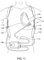
- FIG. 11 is a schematic diagram of an exemplary mechanical circulatory support system 1110 implanted in a subject's body 1112 .
- System 1110 includes a transcutaneous connector 1113 similar to those described above.
- connector 1113 is implemented using components of system 100 (shown in FIG. 1 ) and/or system 200 (shown in FIG. 3 ).
- connector 1113 may include any components that enable system 1110 as would be understood by one of skill from the description herein.
- connector 1113 is not limited to being used with mechanical circulatory support system 1110 , but may be used in any system in which power is supplied transcutaneously to an implanted device.
- Mechanical circulatory support system 1110 includes an implantable blood pump 1114 , ventricular cuff 1116 , outflow cannula 1118 , system controller 1120 , and power sources 1122 .
- One or more components of system controller 1120 and/or power sources 1122 may be implanted within the subject instead of external to the subject as shown in FIG. 11 .
- Implantable blood pump 1114 may include a VAD that is attached to an apex of the left ventricle, as illustrated, or the right ventricle, or both ventricles of the heart 1124 .
- the VAD may include a centrifugal (as shown) or axial flow pump capable of pumping the entire output delivered to the left ventricle from the pulmonary circulation (i.e., up to 10 liters per minute).
- blood pump 1114 may be attached to the heart 1124 via the ventricular cuff 1116 which is sewn to heart 1124 and coupled to blood pump 1114 .
- the other end of blood pump 1114 connects to the ascending aorta via outflow cannula 1118 so that the VAD effectively diverts blood from the weakened ventricle and propels it to the aorta for circulation to the rest of the patient's vascular system.
- mechanical circulatory support system 1110 is configured for a temporary support mode.
- mechanical circulatory support system 1110 is configured to enable a free mode whereby the patient can be supported for a time free from the external components.
- Batteries 1122 and control circuitry can be implanted to operate the pump.
- Connector 1113 facilitates easy disconnection (and reconnection) of the external components.
- a driveline 1126 is connected through connector 1113 .
- Blood pump 1114 is powered by main batteries or another power source outside body 1112 .
- the external portion of driveline 1126 is removed from connector 1113 .
- System 1110 recognizes the disconnection and converts to the free mode by operating using the implanted power source.
- control circuitry includes a state detection module and selects a state based on whether driveline 1126 is connected. For example, in free mode system 1110 can be preprogrammed to operate in a manner to lower the power usage.
- connector 1113 is configured as a breakaway connector. Connector 1113 may be configured such that driveline 1126 can be removed only after a force above a selected threshold is applied. Examples of a breakaway connector are described in U.S. Pat. No. 8,794,989 filed Dec. 8, 2011; U.S. Pat. No. 8,894,561 filed Mar. 5, 2013; U.S. Pat. No. 9,387,285 filed Oct. 16, 2015; and U.S. Pat. No. 8,152,035 filed Jul. 6, 2006, the entire contents of which are incorporated herein in their entirety by reference.
- a mechanical circulatory support system 1110 is connected to battery 1122 for powered operation.
- Batteries 1122 may be external, as shown in FIG. 11 , or may be implanted within the subject's body 1112 (e.g., as described above in association with systems 100 and 200 ).
- Driveline 1126 exits through the subject's skin via connector 1113 and connects implanted blood pump 1114 to system controller 1120 , which monitors system 1110 operation.
- system controller 1120 may be implanted within the subject.
- system controller 1120 and power source 1122 are illustrated outside/external to the subject body, driveline 1126 , system controller 1120 and/or power source 1122 may be partially or fully implantable within the patient, as described above in relation to systems 100 and 200 , and as separate components or integrated with the blood pump 1114 . Examples of such modifications are further described in U.S. Pat. No. 8,562,508 and U.S. Patent Publication No. 2013/0127253, all of which are incorporated herein by reference for all purposes in their entirety.
- the systems described herein may be configured to generate an alert upon detecting a disconnection of connector 1113 (e.g., disconnection of external connector 104 from internal connector 106 (shown in FIG. 1 ), disconnection of power cables 224 and buttons 220 from microconductors 202 and 204 (shown in FIG. 3 ), etc.).
- a disconnection of connector 1113 e.g., disconnection of external connector 104 from internal connector 106 (shown in FIG. 1 ), disconnection of power cables 224 and buttons 220 from microconductors 202 and 204 (shown in FIG. 3 ), etc.
- an internal battery may be used to provide temporary power in the event of a disconnection of connector 1113 .
- the systems described herein may be configured to operate in a temporary support mode, in which the internal components are able to operate autonomously for a period of time after an intentional or unintentional disconnection of connector 1113 .
- the systems described herein include an internal power source (e.g., a battery) capable of supplying power for a predetermined period of time.
- the internal power source may be capable of supporting the patient, for example, for at least twenty minutes, at least thirty minutes, at least forty-five minutes, at least one hour, or at least four hours. Accordingly, the patient could disconnect from external power sources for a period of time (e.g., to take a shower, go for a swim, or participate in other activities that might be difficult or impossible for the patient to undertake without disconnection from external power sources).
- the internal power source may be capable of supporting the patient for extended periods of time (e.g., approximately four to six hours).
- a cover is provided to cover connector 1113 when driveline 1126 is disconnected.
- the cover may comprise a sealing assembly to fluidly seal the electrical contacts of connector 1113 to prevent a short, corrosion, and other issues.
- the sealing assembly may include, for example, one or more hermetic waterproof seals, hermetic waterproof caps, self-healing membranes, and/or other suitable structures capable of preventing exposure from the contacts to the environment.
- the sealing assembly may be formed, for example, on microwire holder 114 , electrical contacts 116 , and/or microneedles 112 (all shown in FIG. 1 ).
- the sealing assembly may be formed, for example, on microconductors 202 and 204 and/or housing 212 (all shown in FIG. 3 ).
- the embodiments described herein use small-diameter conductors to facilitate reducing inflammatory response and risk of infection in a subject.
- the distribution across a plurality of relatively thin conductors may provide increased redundancy while reducing the amount of current going through each conductor. This can lead to lowering corrosive activity and infection risk. Decreasing the size of the conductors and increasing the number of connections may increase redundancy and mitigate against the risk of a short by faulty connections (e.g., a broken conductor or fluid ingress in the connector).
- the small-diameter conductors may be replaced and/or relocated periodically to allow previous power transfer sites to heal.
- internal and external components of the transcutaneous power transfer systems described herein are relatively easy to connect and disconnect from one another.
- the external connector described herein may be replaced by unplugging the microneedle array from the internal connector. If the connection is left open (subject to appropriate clinical treatment to avoid infection, etc.), the small holes from the microneedles can heal and effectively close the exit site. An example where this might be useful is a VAD patient whose heart has recovered.
- a first microneedle array is withdrawn and a second replacement microneedle array is inserted to form a connection to the internal connector.
- the system described herein only forms very small needle holes, facilitating easy connections and disconnections.
Landscapes
- Health & Medical Sciences (AREA)
- Engineering & Computer Science (AREA)
- Heart & Thoracic Surgery (AREA)
- Public Health (AREA)
- Biomedical Technology (AREA)
- Veterinary Medicine (AREA)
- Life Sciences & Earth Sciences (AREA)
- Animal Behavior & Ethology (AREA)
- General Health & Medical Sciences (AREA)
- Cardiology (AREA)
- Anesthesiology (AREA)
- Mechanical Engineering (AREA)
- Hematology (AREA)
- Radiology & Medical Imaging (AREA)
- Nuclear Medicine, Radiotherapy & Molecular Imaging (AREA)
- Vascular Medicine (AREA)
- Computer Networks & Wireless Communication (AREA)
- Power Engineering (AREA)
- Electrotherapy Devices (AREA)
- Media Introduction/Drainage Providing Device (AREA)
- Infusion, Injection, And Reservoir Apparatuses (AREA)
Abstract
Description
where ρ is the resistivity of the material, l is the length of the wire, d is the diameter of the wire, n is the number of wires in the connector, σ is the Stefan-boltzman constant, TR=300K is the room temperature, and ϵ is emissivity.
Claims (14)
Priority Applications (1)
| Application Number | Priority Date | Filing Date | Title |
|---|---|---|---|
| US15/874,026 US11197990B2 (en) | 2017-01-18 | 2018-01-18 | Systems and methods for transcutaneous power transfer using microneedles |
Applications Claiming Priority (3)
| Application Number | Priority Date | Filing Date | Title |
|---|---|---|---|
| US201762447488P | 2017-01-18 | 2017-01-18 | |
| US201762471494P | 2017-03-15 | 2017-03-15 | |
| US15/874,026 US11197990B2 (en) | 2017-01-18 | 2018-01-18 | Systems and methods for transcutaneous power transfer using microneedles |
Publications (2)
| Publication Number | Publication Date |
|---|---|
| US20180200423A1 US20180200423A1 (en) | 2018-07-19 |
| US11197990B2 true US11197990B2 (en) | 2021-12-14 |
Family
ID=61768389
Family Applications (1)
| Application Number | Title | Priority Date | Filing Date |
|---|---|---|---|
| US15/874,026 Active 2038-05-31 US11197990B2 (en) | 2017-01-18 | 2018-01-18 | Systems and methods for transcutaneous power transfer using microneedles |
Country Status (2)
| Country | Link |
|---|---|
| US (1) | US11197990B2 (en) |
| WO (1) | WO2018136592A2 (en) |
Cited By (1)
| Publication number | Priority date | Publication date | Assignee | Title |
|---|---|---|---|---|
| US20210178567A1 (en) * | 2019-06-24 | 2021-06-17 | Milwaukee Electric Tool Corporation | Power tools with high-emissivity heat sinks |
Families Citing this family (16)
| Publication number | Priority date | Publication date | Assignee | Title |
|---|---|---|---|---|
| CN110944689B (en) | 2017-06-07 | 2022-12-09 | 施菲姆德控股有限责任公司 | Intravascular fluid movement devices, systems, and methods of use |
| US11511103B2 (en) | 2017-11-13 | 2022-11-29 | Shifamed Holdings, Llc | Intravascular fluid movement devices, systems, and methods of use |
| US20210046234A1 (en) * | 2017-12-12 | 2021-02-18 | Leviticus Cardio Ltd. | Hybrid powering system for an implanted medical device |
| EP4085965A1 (en) | 2018-02-01 | 2022-11-09 | Shifamed Holdings, LLC | Intravascular blood pumps and methods of use and manufacture |
| WO2020028537A1 (en) | 2018-07-31 | 2020-02-06 | Shifamed Holdings, Llc | Intravascaular blood pumps and methods of use |
| JP7470108B2 (en) | 2018-10-05 | 2024-04-17 | シファメド・ホールディングス・エルエルシー | Intravascular blood pump and method of use |
| EP3730165A1 (en) * | 2019-04-25 | 2020-10-28 | Medela Holding AG | Motor-driven medical suction pump and method for connecting such a suction pump to a power source |
| WO2021011473A1 (en) | 2019-07-12 | 2021-01-21 | Shifamed Holdings, Llc | Intravascular blood pumps and methods of manufacture and use |
| WO2021016372A1 (en) | 2019-07-22 | 2021-01-28 | Shifamed Holdings, Llc | Intravascular blood pumps with struts and methods of use and manufacture |
| US12465748B2 (en) | 2019-08-07 | 2025-11-11 | Supira Medical, Inc. | Catheter blood pumps and collapsible pump housings |
| EP4034192B1 (en) | 2019-09-25 | 2025-12-24 | Supira Medical, Inc. | Intravascular blood pump systems and methods of use and control thereof |
| US12102815B2 (en) | 2019-09-25 | 2024-10-01 | Shifamed Holdings, Llc | Catheter blood pumps and collapsible pump housings |
| WO2021062260A1 (en) | 2019-09-25 | 2021-04-01 | Shifamed Holdings, Llc | Catheter blood pumps and collapsible blood conduits |
| US12409310B2 (en) | 2019-12-11 | 2025-09-09 | Shifamed Holdings, Llc | Descending aorta and vena cava blood pumps |
| US11642512B2 (en) | 2020-08-25 | 2023-05-09 | Medtronic, Inc. | Managing the electric field exposure in a fully implanted LVAD system |
| CN112791306B (en) * | 2021-01-28 | 2025-09-02 | 杭州瑞彼加医疗科技有限公司 | Electrode head and therapeutic device |
Citations (355)
| Publication number | Priority date | Publication date | Assignee | Title |
|---|---|---|---|---|
| US4041955A (en) | 1976-01-29 | 1977-08-16 | Pacesetter Systems Inc. | Implantable living tissue stimulator with an improved hermetic metal container |
| US4352960A (en) | 1980-09-30 | 1982-10-05 | Baptist Medical Center Of Oklahoma, Inc. | Magnetic transcutaneous mount for external device of an associated implant |
| US4561444A (en) | 1981-08-10 | 1985-12-31 | Cordis Corporation | Implantable cardiac pacer having dual frequency programming and bipolar/linipolar lead programmability |
| US4561443A (en) | 1983-03-08 | 1985-12-31 | The Johns Hopkins University | Coherent inductive communications link for biomedical applications |
| US4630615A (en) | 1984-05-21 | 1986-12-23 | Cordis Corporation | Apparatus for measuring impedance |
| US4679560A (en) | 1985-04-02 | 1987-07-14 | Board Of Trustees Of The Leland Stanford Junior University | Wide band inductive transdermal power and data link |
| US4726378A (en) | 1986-04-11 | 1988-02-23 | Minnesota Mining And Manufacturing Company | Adjustable magnetic supercutaneous device and transcutaneous coupling apparatus |
| US4736747A (en) | 1986-04-11 | 1988-04-12 | Minnesota Mining And Manufacturing Company | Adjustable magnetic supercutaneous device and transcutaneous coupling apparatus |
| US4924171A (en) | 1987-10-08 | 1990-05-08 | Tokyo Keiki Co., Ltd. | System for supplying power source by electromagnetic induction coupling |
| US4945305A (en) | 1986-10-09 | 1990-07-31 | Ascension Technology Corporation | Device for quantitatively measuring the relative position and orientation of two bodies in the presence of metals utilizing direct current magnetic fields |
| JPH03109063A (en) | 1989-09-22 | 1991-05-09 | Tanaka Kikinzoku Kogyo Kk | connector |
| US5070223A (en) | 1989-03-01 | 1991-12-03 | Colasante David A | Microwave reheatable clothing and toys |
| US5205286A (en) | 1991-07-24 | 1993-04-27 | Intermedics, Inc. | Subcutaneous electrical data port |
| EP0589608A2 (en) | 1992-09-14 | 1994-03-30 | Aprex Corporation | Contactless communication system |
| US5346458A (en) | 1990-06-25 | 1994-09-13 | Klaus Affeld | Electrohydraulic energy converter for cardiac assist devices and artificial hearts |
| US5350413A (en) | 1990-06-21 | 1994-09-27 | The University Of Ottawa | Transcutaneous energy transfer device |
| US5569156A (en) | 1993-09-10 | 1996-10-29 | Ottawa Heart Institute Research Corporation | Electrohydraulic ventricular assist device |
| US5630836A (en) | 1995-01-19 | 1997-05-20 | Vascor, Inc. | Transcutaneous energy and information transmission apparatus |
| US5690693A (en) | 1995-06-07 | 1997-11-25 | Sulzer Intermedics Inc. | Transcutaneous energy transmission circuit for implantable medical device |
| US5695471A (en) | 1996-02-20 | 1997-12-09 | Kriton Medical, Inc. | Sealless rotary blood pump with passive magnetic radial bearings and blood immersed axial bearings |
| US5702431A (en) | 1995-06-07 | 1997-12-30 | Sulzer Intermedics Inc. | Enhanced transcutaneous recharging system for battery powered implantable medical device |
| US5708346A (en) | 1994-01-10 | 1998-01-13 | Sulzer Electronics Ag | Method and control apparatus for controlling an AC-machine |
| US5755748A (en) | 1996-07-24 | 1998-05-26 | Dew Engineering & Development Limited | Transcutaneous energy transfer device |
| US5771438A (en) | 1995-05-18 | 1998-06-23 | Aura Communications, Inc. | Short-range magnetic communication system |
| US5831248A (en) | 1996-05-23 | 1998-11-03 | Sharp Kabushiki Kaisha | Heat-controlling device |
| US5888242A (en) | 1996-11-01 | 1999-03-30 | Nimbus, Inc. | Speed control system for implanted blood pumps |
| US5948006A (en) | 1998-10-14 | 1999-09-07 | Advanced Bionics Corporation | Transcutaneous transmission patch |
| WO2000001442A2 (en) | 1998-07-06 | 2000-01-13 | Abiomed, Inc. | Transcutaneous energy transfer device with magnetic field protected components in secondary coil |
| US6070103A (en) * | 1996-11-05 | 2000-05-30 | Intermedics Inc. | Apparatus for making direct electrical connection with an implantable medical device |
| US6071093A (en) | 1996-10-18 | 2000-06-06 | Abiomed, Inc. | Bearingless blood pump and electronic drive system |
| US6100618A (en) | 1995-04-03 | 2000-08-08 | Sulzer Electronics Ag | Rotary machine with an electromagnetic rotary drive |
| US6116862A (en) | 1996-06-25 | 2000-09-12 | Medos Medizintechnik Gmbh | Blood pump |
| US6123726A (en) | 1997-07-25 | 2000-09-26 | Seiko Epson Corporation | Portable drive system for artificial heart |
| US6149683A (en) | 1998-10-05 | 2000-11-21 | Kriton Medical, Inc. | Power system for an implantable heart pump |
| WO2000074747A1 (en) | 1999-06-03 | 2000-12-14 | Arrow International, Inc. | Ventricular assist device |
| US6186665B1 (en) | 1999-01-26 | 2001-02-13 | Nimbus, Inc. | Motor rotor bearing assembly for a blood pump |
| US6212430B1 (en) | 1999-05-03 | 2001-04-03 | Abiomed, Inc. | Electromagnetic field source with detection of position of secondary coil in relation to multiple primary coils |
| US6234772B1 (en) | 1999-04-28 | 2001-05-22 | Kriton Medical, Inc. | Rotary blood pump |
| WO2001037926A1 (en) | 1999-11-22 | 2001-05-31 | Abiomed, Inc. | Apparatus for transferring energy across a boundary |
| US6264635B1 (en) | 1998-12-03 | 2001-07-24 | Kriton Medical, Inc. | Active magnetic bearing system for blood pump |
| US6296533B1 (en) | 1998-08-31 | 2001-10-02 | The Whitaker Corporation | Electrical receptacle contact |
| US6312338B1 (en) | 1998-10-21 | 2001-11-06 | Nintendo Company, Ltd. | Electronic accessory for game machine |
| US6320354B1 (en) | 2000-07-21 | 2001-11-20 | Motorola, Inc. | Method and apparatus for battery charging |
| US6327504B1 (en) | 2000-05-10 | 2001-12-04 | Thoratec Corporation | Transcutaneous energy transfer with circuitry arranged to avoid overheating |
| US6334856B1 (en) * | 1998-06-10 | 2002-01-01 | Georgia Tech Research Corporation | Microneedle devices and methods of manufacture and use thereof |
| US6365996B2 (en) | 1995-08-18 | 2002-04-02 | Lust Antriebstechnik Gmbh | Radial active magnetic bearing apparatus and a method for operating the same |
| US6389318B1 (en) | 1998-07-06 | 2002-05-14 | Abiomed, Inc. | Magnetic shield for primary coil of transcutaneous energy transfer device |
| US20020087204A1 (en) | 2001-01-04 | 2002-07-04 | Kung Robert T. V. | Flexible transcutaneous energy transfer (TET) primary coil |
| US20020093456A1 (en) | 2000-12-11 | 2002-07-18 | Masatoshi Sawamura | Dual band built-in antenna device and mobile wireless terminal equipped therewith |
| US6442434B1 (en) | 1999-10-19 | 2002-08-27 | Abiomed, Inc. | Methods and apparatus for providing a sufficiently stable power to a load in an energy transfer system |
| US6451055B1 (en) | 2000-04-25 | 2002-09-17 | The Penn State Research Foundation | Artificial heart data communication system |
| US20020138049A1 (en) * | 1998-06-10 | 2002-09-26 | Allen Mark G. | Microneedle devices and methods of manufacture and use thereof |
| US6458164B1 (en) | 2000-04-25 | 2002-10-01 | The Penn State Research Foundation | Artificial heart with energy recovery |
| US6478820B1 (en) | 2000-04-25 | 2002-11-12 | The Penn State Research Foundation | Artificial heart with synchronous rectification |
| KR20020089605A (en) | 2001-05-23 | 2002-11-30 | 안태영 | Apparatus for contactless power transfer for medical implant |
| US6553263B1 (en) | 1999-07-30 | 2003-04-22 | Advanced Bionics Corporation | Implantable pulse generators using rechargeable zero-volt technology lithium-ion batteries |
| US6579315B1 (en) | 2000-04-25 | 2003-06-17 | The Penn State Research Foundation | Artificial heart power supply system |
| US6591139B2 (en) | 2000-09-06 | 2003-07-08 | Advanced Bionics Corporation | Low-power, high-modulation-index amplifier for use in battery-powered device |
| US6605032B2 (en) | 1997-10-02 | 2003-08-12 | Micromed Technology, Inc. | Implantable pump system |
| US20030171792A1 (en) | 1998-07-06 | 2003-09-11 | Farhad Zarinetchi | Transcutaneous energy transfer module with integrated conversion circuitry |
| US6647298B2 (en) | 2001-06-04 | 2003-11-11 | St. Jude Medical Ab | Implantable medical device with variable incoming communication signal discrimination, and method for operating same |
| US6650213B1 (en) | 2000-06-02 | 2003-11-18 | Yamatake Corporation | Electromagnetic-induction coupling apparatus |
| US6688861B2 (en) | 1996-02-20 | 2004-02-10 | Heartware, Inc. | Sealless rotary blood pump |
| US6723039B2 (en) | 2001-04-27 | 2004-04-20 | The Foundry, Inc. | Methods, systems and devices relating to implantable fluid pumps |
| US20040138725A1 (en) | 2002-09-20 | 2004-07-15 | Peter Forsell | Harmless wireless energy transmission to implant |
| US6772011B2 (en) | 2002-08-20 | 2004-08-03 | Thoratec Corporation | Transmission of information from an implanted medical device |
| US6801807B2 (en) | 2001-01-31 | 2004-10-05 | St. Jude Medical Ab | Communication system and method for communicating between an implanted medical device and another device |
| US6810289B1 (en) | 2000-04-20 | 2004-10-26 | Cochlear Limited | Transcutaneous power optimization circuit for cochlear implant |
| US20040256146A1 (en) | 2003-06-17 | 2004-12-23 | W.C. Heraeus Gmbh & Co., Kg | Electrode structure and methods for producing and using the same |
| US20050006083A1 (en) | 2003-07-02 | 2005-01-13 | Yin-Yuan Chen | Temperature-homogenizing device |
| US6850803B1 (en) | 2000-06-16 | 2005-02-01 | Medtronic, Inc. | Implantable medical device with a recharging coil magnetic shield |
| EP1513241A1 (en) | 2002-05-23 | 2005-03-09 | Limited Company TM | Non-intrusion type charging system for artificial organ, capacitor and power supplying device used in the system |
| US20050071001A1 (en) | 2003-09-30 | 2005-03-31 | Robert Jarvik | Artificial heart power and control system |
| US20050090883A1 (en) | 1998-08-12 | 2005-04-28 | Cardiac Pacemakers, Inc. | Seal for use with medical device and system |
| US6895281B1 (en) | 2000-03-31 | 2005-05-17 | Cardiac Pacemakers, Inc. | Inductive coil apparatus for bio-medical telemetry |
| US6894456B2 (en) | 2001-11-07 | 2005-05-17 | Quallion Llc | Implantable medical power module |
| US6949065B2 (en) | 2001-04-20 | 2005-09-27 | DEUTSCHES ZENTRUM FüR LUFT-UND RAUMFAHRT E.V. | Left ventricular assist system |
| US6960968B2 (en) | 2002-06-26 | 2005-11-01 | Koninklijke Philips Electronics N.V. | Planar resonator for wireless power transfer |
| WO2005106901A2 (en) | 2004-05-04 | 2005-11-10 | Philips Intellectual Property & Standards Gmbh | A wireless powering device, an energizable load, a wireless system and a method for a wireless energy transfer |
| US6967621B1 (en) | 2004-03-16 | 2005-11-22 | The United States Of America As Represented By The Secretary Of The Army | Small low profile antennas using high impedance surfaces and high permeability, high permittivity materials |
| US6985773B2 (en) | 2002-02-07 | 2006-01-10 | Cardiac Pacemakers, Inc. | Methods and apparatuses for implantable medical device telemetry power management |
| US6991595B2 (en) | 2002-04-19 | 2006-01-31 | Thoratec Corporation | Adaptive speed control for blood pump |
| US7015769B2 (en) | 2002-06-20 | 2006-03-21 | Alfred E. Mann Foundation For Scientific Research | System and method for automatic tuning of a magnetic field generator |
| US20060199997A1 (en) | 2005-02-24 | 2006-09-07 | Ethicon Endo-Surgery, Inc. | Monitoring of a food intake restriction device |
| US7107103B2 (en) | 1997-02-26 | 2006-09-12 | Alfred E. Mann Foundation For Scientific Research | Full-body charger for battery-powered patient implantable device |
| US7126310B1 (en) | 2001-04-20 | 2006-10-24 | Abiomed, Inc. | Apparatus and method for balanced charging of a multiple-cell battery pack |
| US20060271129A1 (en) | 2005-05-27 | 2006-11-30 | California Institute Of Technology | Magnetic material-containing microfabricated devices for wireless data and power transfer |
| US20070078293A1 (en) | 2005-10-05 | 2007-04-05 | Shambaugh Charles R Jr | Impeller for a rotary ventricular assist device |
| US20070096686A1 (en) | 2005-05-06 | 2007-05-03 | Medtronic, Inc. | Implantable device with heat absorption material |
| WO2007053881A1 (en) | 2005-11-08 | 2007-05-18 | Ventrassist Pty Ltd | Improvements to control systems and power systems for rotary blood pumps |
| US7225032B2 (en) | 2003-10-02 | 2007-05-29 | Medtronic Inc. | External power source, charger and system for an implantable medical device having thermal characteristics and method therefore |
| US20070123948A1 (en) | 2005-09-01 | 2007-05-31 | Ela Medical S.A.S | Telemetry apparatus for communications with an active device implanted in a patient's thoracic region |
| US20070142696A1 (en) | 2005-12-08 | 2007-06-21 | Ventrassist Pty Ltd | Implantable medical devices |
| US7246040B2 (en) | 2004-09-15 | 2007-07-17 | Deutsches Zentrum für Luft- und Raumfahrt e.V. | Process of remote sensing data |
| US20070191706A1 (en) | 2005-05-12 | 2007-08-16 | General Electric Company | Patient table system and apparatus |
| US7286880B2 (en) | 2003-10-02 | 2007-10-23 | Medtronic, Inc. | System and method for transcutaneous energy transfer achieving high efficiency |
| US20080009198A1 (en) | 2004-08-27 | 2008-01-10 | Marino Jay C | Flexible connector for implantable wiring harness |
| US20080021394A1 (en) | 2006-01-13 | 2008-01-24 | Larose Jeffrey A | Stabilizing drive for contactless rotary blood pump impeller |
| US20080027293A1 (en) | 2006-07-27 | 2008-01-31 | Deutsches Zentrum Fuer Luft-Und Raumfahrt E.V. | Transfer assembly |
| US20080054638A1 (en) | 2006-09-01 | 2008-03-06 | Powercast Corporation | Hybrid power harvesting and method |
| US20080100294A1 (en) | 2006-10-31 | 2008-05-01 | Rohling Kenneth W | Flexible rf coil assembly and method of making same |
| WO2008066941A2 (en) | 2006-03-31 | 2008-06-05 | University Of Pittsburgh-Of The Commonwealth System Of Higher Education | A portable apparatus that delivers power and information to implantable devices |
| US20080149736A1 (en) | 2006-12-21 | 2008-06-26 | Korea Advanced Institute Of Science And Technology | System-in-package having reduced influence between conductor and antenna and method of designing the same |
| US20080167531A1 (en) | 2007-01-05 | 2008-07-10 | Cardiac Pacemakers, Inc. | System and method to monitor battery status in an implantable medical device |
| US20080211320A1 (en) | 2007-03-02 | 2008-09-04 | Nigelpower, Llc | Wireless power apparatus and methods |
| US7428438B2 (en) | 2002-06-28 | 2008-09-23 | Boston Scientific Neuromodulation Corporation | Systems and methods for providing power to a battery in an implantable stimulator |
| US7471986B2 (en) | 2004-02-20 | 2008-12-30 | Cardiac Pacemakers, Inc. | System and method for transmitting energy to and establishing a communications network with one or more implanted devices |
| US20090018616A1 (en) | 2006-07-17 | 2009-01-15 | Advanced Bionics, Llc | Systems and Methods for Determining a Threshold Current Level Required to Evoke a Stapedial Muscle Reflex |
| WO2009018271A1 (en) | 2007-08-02 | 2009-02-05 | University Of Pittsburgh-Of The Commonwealth System Of Higher Education | Wireless systems having multiple electronic devices and employing simplified fabrication and matching, and associated methods |
| WO2009021220A1 (en) | 2007-08-08 | 2009-02-12 | Radeum, Inc. | Near field communications system having enhanced security |
| US7496733B2 (en) | 2004-04-21 | 2009-02-24 | International Business Machines Corporation | System and method of execution of register pointer instructions ahead of instruction issues |
| US20090051224A1 (en) | 2007-03-02 | 2009-02-26 | Nigelpower, Llc | Increasing the q factor of a resonator |
| WO2009023905A1 (en) | 2007-08-17 | 2009-02-26 | Ventrassist Pty Ltd | Transcutaneous energy transfer coil assemblies and systems |
| US7505816B2 (en) | 2005-04-29 | 2009-03-17 | Medtronic, Inc. | Actively cooled external energy source, external charger, system of transcutaneous energy transfer, system of transcutaneous charging and method therefore |
| US20090072628A1 (en) | 2007-09-13 | 2009-03-19 | Nigel Power, Llc | Antennas for Wireless Power applications |
| US20090081943A1 (en) | 2007-09-26 | 2009-03-26 | Radeum, Inc. Dba Freelinc | System and method for near field communications having local security |
| US7515012B2 (en) | 2002-06-20 | 2009-04-07 | Alfred E. Mann Foundation For Scientific Research | System and method for automatic tuning of a magnetic field generator |
| US7522878B2 (en) | 1999-06-21 | 2009-04-21 | Access Business Group International Llc | Adaptive inductive power supply with communication |
| US7532901B1 (en) | 2001-03-16 | 2009-05-12 | Radeum, Inc. | Methods and apparatus to detect location and orientation in an inductive system |
| US20090174264A1 (en) | 2008-01-09 | 2009-07-09 | Seiko Epson Corporation | Power transmission control device, power transmitting device, non-contact power transmission system, electronic instrument, and power transmission control method |
| US7565187B1 (en) | 2002-04-11 | 2009-07-21 | Radeum, Inc. | Transceiver device and fastener |
| US7571007B2 (en) | 2004-04-12 | 2009-08-04 | Advanced Neuromodulation Systems, Inc. | Systems and methods for use in pulse generation |
| US7574173B2 (en) | 2001-03-16 | 2009-08-11 | Radeum, Inc. | Wireless communication over a transducer device |
| US20090203957A1 (en) | 2008-02-08 | 2009-08-13 | Larose Jeffrey A | Ventricular assist device for intraventricular placement |
| US20090212736A1 (en) | 2008-02-22 | 2009-08-27 | Access Business Group International Llc | Inductive power supply system with battery type detection |
| US7587241B2 (en) | 2002-06-28 | 2009-09-08 | Boston Scientific Neuromodulation Corporation | Method for controlling telemetry in an implantable medical device based on power source capacity |
| US20090226328A1 (en) | 2004-11-16 | 2009-09-10 | Micromed Technology, Inc. | Remote Data Monitor For Heart Pump System |
| US7599743B2 (en) | 2004-06-24 | 2009-10-06 | Ethicon Endo-Surgery, Inc. | Low frequency transcutaneous energy transfer to implanted medical device |
| US20090270679A1 (en) | 2008-04-25 | 2009-10-29 | Hans David Hoeg | Wirelessly powered medical devices and instruments |
| US20090284220A1 (en) | 2008-05-13 | 2009-11-19 | Qualcomm Incorporated | Method and apparatus for adaptive tuning of wireless power transfer |
| US7650187B2 (en) | 2003-11-18 | 2010-01-19 | DEUTSCHES ZENTRUM FüR LUFT-UND RAUMFAHRT E.V. | Assembly for wireless energy communication to an implanted device |
| US7650192B2 (en) | 2005-12-02 | 2010-01-19 | Medtronic, Inc. | Passive charge of implantable medical device utilizing external power source and method |
| US20100019985A1 (en) | 2008-07-24 | 2010-01-28 | Jacob Bashyam | Header with integral antenna for implantable medical devices |
| US20100035453A1 (en) | 2005-10-31 | 2010-02-11 | Medtronic, Inc. | Axial lead connector for implantable medical device |
| US20100033021A1 (en) | 2008-08-05 | 2010-02-11 | Broadcom Corporation | Phased array wireless resonant power delivery system |
| US20100045114A1 (en) | 2008-08-20 | 2010-02-25 | Sample Alanson P | Adaptive wireless power transfer apparatus and method thereof |
| US20100063347A1 (en) | 2008-09-10 | 2010-03-11 | Barry Yomtov | Tet system for implanted medical device |
| US20100069992A1 (en) | 2000-03-17 | 2010-03-18 | Boston Scientific Neuromodulation Corporation | Implantable Medical Device with Single Coil for Charging and Communicating |
| US20100066305A1 (en) | 2006-11-08 | 2010-03-18 | Panasonic Corporation | Contactless battery charger, electronic device, battery pack, and contactless charging system |
| US7699586B2 (en) | 2004-12-03 | 2010-04-20 | Heartware, Inc. | Wide blade, axial flow pump |
| US7711433B2 (en) | 2004-07-20 | 2010-05-04 | Medtronic, Inc. | Switched power using telemetry in an implantable medical device |
| US20100114143A1 (en) | 2008-10-30 | 2010-05-06 | Albrecht Thomas E | Wearable elements for intra-gastric satiety creations systems |
| US20100109958A1 (en) | 2008-10-31 | 2010-05-06 | Haubrich Gregory J | High Dielectric Substrate Antenna For Implantable Miniaturized Wireless Communications and Method for Forming the Same |
| US7720546B2 (en) | 2004-09-30 | 2010-05-18 | Codman Neuro Sciences Sárl | Dual power supply switching circuitry for use in a closed system |
| US20100122995A1 (en) | 2008-11-18 | 2010-05-20 | Thoratec Corporation | Medical Device Accessory Carrier |
| US7741734B2 (en) | 2005-07-12 | 2010-06-22 | Massachusetts Institute Of Technology | Wireless non-radiative energy transfer |
| US20100171368A1 (en) | 2008-09-27 | 2010-07-08 | Schatz David A | Wireless energy transfer with frequency hopping |
| US7761164B2 (en) | 2005-11-30 | 2010-07-20 | Medtronic, Inc. | Communication system for medical devices |
| US20100184371A1 (en) | 2008-09-17 | 2010-07-22 | Qualcomm Incorporated | Transmitters for wireless power transmission |
| US20100194334A1 (en) | 2008-11-20 | 2010-08-05 | Qualcomm Incorporated | Retrofitting wireless power and near-field communication in electronic devices |
| US7774069B2 (en) | 2005-04-29 | 2010-08-10 | Medtronic, Inc. | Alignment indication for transcutaneous energy transfer |
| WO2010089354A2 (en) | 2009-02-04 | 2010-08-12 | Infineon Technologies Ag | Determining device, method for determining of transmitting parameter, energy transmitting device and method for wirelessly transmitting energy |
| US20100211134A1 (en) | 2007-10-16 | 2010-08-19 | Peter Forsell | Method and apparatus for supplying energy to a medical device |
| US20100210233A1 (en) | 2008-09-08 | 2010-08-19 | Qualcomm Incorporated | Receive antenna arrangement for wireless power |
| US7782190B1 (en) | 2004-04-19 | 2010-08-24 | Advanced Neuromodulation Systems, Inc. | Implantable device and system and method for wireless communication |
| US20100222848A1 (en) | 2007-10-16 | 2010-09-02 | Peter Forsell | Method and apparatus for supplying energy to a medical device |
| US20100225174A1 (en) | 2009-03-05 | 2010-09-09 | Hao Jiang | Wireless Power Transfer Using Magnets |
| US7805200B2 (en) | 2000-06-19 | 2010-09-28 | Medtronic, Inc. | Implantable medical device with external housing for a recharging coil |
| US20100244576A1 (en) | 2009-03-25 | 2010-09-30 | Qualcomm Incorporated | Optimization of wireless power devices |
| US20100253340A1 (en) | 2009-04-02 | 2010-10-07 | Regents Of The University Of Minnesota | Adiabatic magnetization preparation for b1 and b0 insensitive high contrast mri |
| US20100256708A1 (en) | 2009-04-03 | 2010-10-07 | Thornton Arnold W | Implantable device with heat storage |
| US7812481B2 (en) | 2007-06-29 | 2010-10-12 | Seiko Epson Corporation | Power transmission control device, power transmission device, electronic instrument, and non-contact power transmission system |
| US20100262135A1 (en) | 2009-04-14 | 2010-10-14 | Primaeva Medical, Inc. | Controlled delivery of therapeutic energy to tissue |
| US7818036B2 (en) | 2003-09-19 | 2010-10-19 | Radeum, Inc. | Techniques for wirelessly controlling push-to-talk operation of half-duplex wireless device |
| US7818037B2 (en) | 2003-09-19 | 2010-10-19 | Radeum, Inc. | Techniques for wirelessly controlling push-to-talk operation of half-duplex wireless device |
| US7825543B2 (en) | 2005-07-12 | 2010-11-02 | Massachusetts Institute Of Technology | Wireless energy transfer |
| US20100277121A1 (en) | 2008-09-27 | 2010-11-04 | Hall Katherine L | Wireless energy transfer between a source and a vehicle |
| US7830114B2 (en) | 2007-06-14 | 2010-11-09 | Visteon Global Technologies, Inc. | Flex circuit interface for wireless charging |
| US20100308939A1 (en) | 2008-09-27 | 2010-12-09 | Kurs Andre B | Integrated resonator-shield structures |
| US20100314946A1 (en) | 2006-10-26 | 2010-12-16 | Koninklijke Philips Electronics N.V. | Floor covering and inductive power system |
| EP2267864A2 (en) | 2009-06-25 | 2010-12-29 | Panasonic Electric Works Co., Ltd. | Non-contact charger with an indicator |
| US20100331919A1 (en) | 2009-06-30 | 2010-12-30 | Boston Scientific Neuromodulation Corporation | Moldable charger having hinged sections for charging an implantable pulse generator |
| US7865245B2 (en) | 2000-04-28 | 2011-01-04 | Medtronic, Inc. | Battery recharge management for implantable medical device |
| US7872367B2 (en) | 2005-12-13 | 2011-01-18 | Airbus Deutschland Gmbh | Method and device for redundantly supplying several electric servomotors or drive motors by means of a common power electronics unit |
| US20110025132A1 (en) | 2008-04-22 | 2011-02-03 | Olympus Corporation | Power transmission system |
| US20110046699A1 (en) | 2009-08-20 | 2011-02-24 | Envoy Medical Corporation | Self-regulating transcutaneous energy transfer |
| US20110043050A1 (en) | 2008-05-22 | 2011-02-24 | Mitsubishi Electric Corporation | Electronic equipment and method for connecting electronic circuit substrate |
| US7904170B2 (en) | 2007-01-26 | 2011-03-08 | Medtronic, Inc. | Radio frequency transponder based implantable medical system |
| US7932696B2 (en) | 2007-05-14 | 2011-04-26 | Boston Scientific Neuromodulation Corporation | Charger alignment indicator with adjustable threshold |
| US20110101790A1 (en) | 2008-01-18 | 2011-05-05 | Telemetry Research Limited | Selectable resonant frequency transcutaneous energy transfer system |
| US20110109263A1 (en) | 2009-11-09 | 2011-05-12 | Kabushiki Kaisha Toyota Jidoshokki | Resonance type non-contact charging apparatus |
| US20110115431A1 (en) | 2009-11-17 | 2011-05-19 | Qualcomm Incorporated | Selective wireless power transfer |
| US20110127848A1 (en) | 2009-11-30 | 2011-06-02 | Samsung Electronics Co., Ltd. | Wireless Power Transceiver and Wireless Power System |
| US7962222B2 (en) | 2005-12-07 | 2011-06-14 | Boston Scientific Neuromodulation Corporation | Battery protection and zero-volt battery recovery system for an implantable medical device |
| US20110148215A1 (en) | 2009-12-21 | 2011-06-23 | Alcatel-Lucent Usa Inc. | Automatic tuning for wireless power transfer |
| WO2011081626A1 (en) | 2009-12-30 | 2011-07-07 | Thoratec Corporation | Mobility-enhancing blood pump system |
| GB2477034A (en) | 2010-01-15 | 2011-07-20 | Wfs Technologies Ltd | Subsea system providing inductive power transfer and acoustic and/or radio communication of navigation information and other data |
| US20110178361A1 (en) | 2010-01-19 | 2011-07-21 | Barry Yomtov | Physiologically responsive vad |
| US20110181235A1 (en) | 2010-01-26 | 2011-07-28 | Broadcom Corporation | Smart Charging System and Related Method |
| US20110205083A1 (en) | 2007-09-06 | 2011-08-25 | Smith & Nephew, Inc. | System and method for communicating with a telemetric implant |
| USRE42682E1 (en) | 1996-08-01 | 2011-09-06 | Medtronic, Inc. | RF coupled, implantable medical device with rechargeable back-up power source |
| WO2011113934A1 (en) | 2010-03-18 | 2011-09-22 | Deutsches Zentrum für Luft- und Raumfahrt e.V. | Device for supplying energy to hydraulically or pneumatically actuated active implants |
| US20110234011A1 (en) | 2010-03-29 | 2011-09-29 | Samsung Electronics Co., Ltd. | Power receiving apparatus and wireless power transceiving system |
| US20110234155A1 (en) | 2010-03-26 | 2011-09-29 | Boston Scientific Neuromodulation Corporation | Inductive Charger with Magnetic Shielding |
| US20110245892A1 (en) | 2010-04-05 | 2011-10-06 | Medtronic, Inc. | Flexible recharge coil techniques |
| US20110241436A1 (en) | 2010-04-02 | 2011-10-06 | Advantest Corporation | Wireless power receiving apparatus and wireless power supply system |
| US20110241750A1 (en) | 2008-11-14 | 2011-10-06 | Cambridge Resonant Technologies Ltd. | Tuned resonant circuits |
| US20110266880A1 (en) | 2010-05-03 | 2011-11-03 | Samsung Electronics Co., Ltd. | Apparatus and method of matching in a source-target structure |
| US20110276110A1 (en) | 2010-05-07 | 2011-11-10 | Boston Scientific Neuromodulation Corporation | Power Circuitry for an Implantable Medical Device Using a DC-DC Converter |
| US20110278948A1 (en) | 2008-11-21 | 2011-11-17 | Milux Holdings SA | System for supplying energy |
| US8062783B2 (en) | 2006-12-01 | 2011-11-22 | Tti Ellebeau, Inc. | Systems, devices, and methods for powering and/or controlling devices, for instance transdermal delivery devices |
| US20110291489A1 (en) | 2010-05-31 | 2011-12-01 | Tsai Ming-Chiu | Power transmission method of high-power wireless induction power supply system |
| US20110295345A1 (en) | 2010-05-28 | 2011-12-01 | Lockheed Martin Corporation | Implantable infrared nerve stimulation devices for peripheral and cranial nerve interfaces |
| US20110291613A1 (en) | 2010-05-28 | 2011-12-01 | Qualcomm Incorporated | Temperature sensor interface for wireless and wired charging |
| US20110298294A1 (en) | 2008-11-04 | 2011-12-08 | Toyota Jidosha Kabushiki Kaisha | Non-contact power transmission device and design method thereof |
| US20110301667A1 (en) | 2003-10-02 | 2011-12-08 | Medtronic, Inc. | Inductively rechargeable external energy source, charger, system and method for a transcutaneous inductive charger for an implantable medical device |
| US8076807B2 (en) | 2006-09-28 | 2011-12-13 | Robert Bosch Gmbh | Connection system comprising an external cable guide on wiper motor housings |
| US8081925B2 (en) | 2008-05-08 | 2011-12-20 | Boston Scientific Neuromodulation Corporation | Transceiver for an implantable medical device having switchable series-to-parallel tank circuit |
| US20110313238A1 (en) | 2010-06-22 | 2011-12-22 | Reichenbach Steven H | Fluid delivery system and method for monitoring fluid delivery system |
| WO2012002063A1 (en) | 2010-06-30 | 2012-01-05 | パナソニック電工 株式会社 | Non-contact electric power feeding system and metal foreign-object detection apparatus for non-contact electric power feeding system |
| US20120001485A1 (en) | 2009-03-30 | 2012-01-05 | Fujitsu Limited | Wireless power supply system, wireless power transmitting device, and wireless power receiving device |
| US8096954B2 (en) | 2006-11-29 | 2012-01-17 | Cardiac Pacemakers, Inc. | Adaptive sampling of heart sounds |
| KR20120007296A (en) | 2010-07-14 | 2012-01-20 | 한국전기연구원 | Wireless power transmission system and method for in vivo sensor |
| US20120032522A1 (en) | 2008-09-27 | 2012-02-09 | Schatz David A | Wireless energy transfer for implantable devices |
| US20120039102A1 (en) | 2009-04-27 | 2012-02-16 | Murata Manufacturing Co., Ltd. | Wireless power transfer terminal |
| US20120046514A1 (en) | 2010-08-20 | 2012-02-23 | Kevin Bourque | Implantable blood pump |
| US20120057322A1 (en) | 2009-05-20 | 2012-03-08 | Koninklijke Philips Electronics N.V. | Electronic device having an inductive receiver coil with ultra-thin shielding layer and method |
| US20120065458A1 (en) | 2009-05-15 | 2012-03-15 | Koninklijke Philips Electronics N.V. | Implantable device with communication means |
| US8140168B2 (en) | 2003-10-02 | 2012-03-20 | Medtronic, Inc. | External power source for an implantable medical device having an adjustable carrier frequency and system and method related therefore |
| US8150529B2 (en) | 2008-04-16 | 2012-04-03 | Pacesetter, Inc. | Medical devices and systems having separate power sources for enabling different telemetry systems |
| US20120080957A1 (en) | 2008-08-20 | 2012-04-05 | Cooper Emily B | Wireless power transfer apparatus and method thereof |
| US8152493B2 (en) | 2007-04-30 | 2012-04-10 | Hearthware Inc. | Centrifugal rotary blood pump with impeller having a hydrodynamic thrust bearing surface |
| US20120091951A1 (en) | 2010-10-19 | 2012-04-19 | Sohn Hyun Yeo | Apparatus and method for displaying measured strength in wirelessly charging battery |
| US20120095281A1 (en) | 2010-10-13 | 2012-04-19 | Reichenbach Steven H | Pumping blood |
| US8165694B2 (en) | 2008-01-29 | 2012-04-24 | Boston Scientific Neuromodulation Corporation | Thermal management of implantable medical devices |
| US20120104997A1 (en) | 2010-11-01 | 2012-05-03 | Qualcomm Incorporated | Wireless charging device |
| US20120109256A1 (en) | 2010-10-28 | 2012-05-03 | Werner Meskins | Magnetic induction communication system for an implantable medical device |
| WO2012056365A2 (en) | 2010-10-28 | 2012-05-03 | Koninklijke Philips Electronics N.V. | Wireless electrical power supply unit and arrangement comprising a light transmissive cover and lighting system |
| US20120119914A1 (en) | 2009-07-23 | 2012-05-17 | Fujitsu Limited | Power transmission device, wireless power supply system, and wireless power supply device |
| US8193766B2 (en) | 2008-04-30 | 2012-06-05 | Medtronic, Inc. | Time remaining to charge an implantable medical device, charger indicator, system and method therefore |
| US20120150259A1 (en) | 2010-12-10 | 2012-06-14 | Werner Meskens | Portable power charging of implantable medical devices |
| US20120146575A1 (en) | 2010-12-10 | 2012-06-14 | EverHeart Systems LLC | Implantable wireless power system |
| US20120149229A1 (en) | 2010-12-08 | 2012-06-14 | Keith Hamilton Kearsley | Modular driveline |
| US8203434B2 (en) | 2006-06-13 | 2012-06-19 | Olympus Corporation | Wireless power feeding system and capsule endoscope system applied with the same |
| US20120153954A1 (en) | 2010-11-17 | 2012-06-21 | Ota Miyuki | Rf coil device and magnetic resonance imaging apparatus |
| US20120158407A1 (en) | 2008-10-10 | 2012-06-21 | Milux Holding Sa | Voice control system for an implant |
| US20120157754A1 (en) | 2010-12-20 | 2012-06-21 | Abiomed, Inc. | Compact battery and controller module for a transcutaneous energy transfer system |
| US20120157753A1 (en) | 2010-12-20 | 2012-06-21 | Abiomed, Inc. | Transcutaneous energy transfer system with multiple secondary coils |
| US20120153739A1 (en) | 2010-12-21 | 2012-06-21 | Cooper Emily B | Range adaptation mechanism for wireless power transfer |
| WO2012087819A2 (en) | 2010-12-20 | 2012-06-28 | Abiomed, Inc. | Transcutaneous energy transfer system with vibration inducing warning circuitry |
| US20120164943A1 (en) | 2008-08-05 | 2012-06-28 | Broadcom Corporation | Integrated wireless resonant power charging and communication channel |
| WO2012087816A2 (en) | 2010-12-20 | 2012-06-28 | Abiomed, Inc. | Method and apparatus for accurately tracking available charge in a transcutaneous energy transfer system |
| US20120161539A1 (en) | 2010-12-23 | 2012-06-28 | Nam Yun Kim | System for wireless power transmission and reception using in-band communication |
| US20120169139A1 (en) | 2009-12-24 | 2012-07-05 | Kabushiki Kaisha Toshiba | Wireless power transmission apparatus |
| US20120169137A1 (en) | 2010-12-29 | 2012-07-05 | Gianpaolo Lisi | Resonant system for wireless power transmission to multiple receivers |
| US20120169133A1 (en) | 2010-12-29 | 2012-07-05 | Gianpaolo Lisi | Transmitter and receiver tuning in a wireless charging system |
| US20120169278A1 (en) | 2011-01-03 | 2012-07-05 | Samsung Electronics Co., Ltd. | Wireless power transmission apparatus and system for wireless power transmission thereof |
| US20120169132A1 (en) | 2010-12-29 | 2012-07-05 | Choudhary Vijay N | Resonance tuning |
| KR20120077448A (en) | 2010-12-30 | 2012-07-10 | 전자부품연구원 | Wireless power transmission apparatus using magnetic resonance induction capable of detecting obstacles |
| US20120175967A1 (en) | 2007-12-21 | 2012-07-12 | Access Business Group International Llc | Inductive power transfer |
| WO2012099965A2 (en) | 2011-01-18 | 2012-07-26 | Afshin Partovi | Systems and methods for providing positioning freedom, and support of different voltages, protocols, and power levels in a wireless power system |
| US8244367B2 (en) | 2007-10-26 | 2012-08-14 | Medtronic, Inc. | Closed loop long range recharging |
| US8247926B2 (en) | 2007-11-27 | 2012-08-21 | Extremely Ingenious Engineering, Llc | Methods and systems for wireless energy and data transmission |
| US8258653B2 (en) | 2009-01-27 | 2012-09-04 | Panasonic Corporation | Contactless power transmission system |
| US8265770B2 (en) | 2003-10-02 | 2012-09-11 | Medtronic, Inc. | Driver circuitry switchable between energy transfer and telemetry for an implantable medical device |
| US20120235364A1 (en) | 2011-03-18 | 2012-09-20 | Wang Zhensheng | Compressive stress water stopper |
| US20120239118A1 (en) | 2009-05-26 | 2012-09-20 | Boston Scientific Neuromodulation Corporation | Techniques for Controlling Charging of Batteries in an External Charger and an Implantable Medical Device |
| US20120245649A1 (en) | 2011-03-21 | 2012-09-27 | General Electric Company | System and method for contactless power transfer in implantable devices |
| US20120245664A1 (en) | 2011-03-22 | 2012-09-27 | Greatbatch Ltd. | Thin profile stacked layer contact |
| US8278784B2 (en) | 2008-07-28 | 2012-10-02 | Qualcomm Incorporated | Wireless power transmission for electronic devices |
| US20120259398A1 (en) | 2009-07-21 | 2012-10-11 | Boston Scientific Neuromodulation Corporation | Spring passive lead anchor and methods and devices using the anchor |
| WO2012141752A2 (en) | 2011-04-14 | 2012-10-18 | Abiomed Inc. | Transcutaneous energy transfer coil with integrated radio frequency antenna |
| US8292052B2 (en) | 2010-06-24 | 2012-10-23 | General Electric Company | Power transfer system and method |
| US8299652B2 (en) | 2008-08-20 | 2012-10-30 | Intel Corporation | Wireless power transfer apparatus and method thereof |
| US20120274148A1 (en) | 2011-04-27 | 2012-11-01 | Samsung Electro-Mechanics Co., Ltd. | Contactless power transmission device and electronic device having the same |
| US8319473B2 (en) | 2010-04-05 | 2012-11-27 | Samsung Electro-Mechanics Co., Ltd. | Wireless energy transmission structure |
| US8323174B2 (en) | 2010-10-22 | 2012-12-04 | Nupulse, Inc. | Skin interface for ventricular assist device |
| US20120306433A1 (en) | 2011-05-31 | 2012-12-06 | Nam Yun Kim | Wireless power transmission and charging system, and power control method of wireless power transmission and charging system |
| US20130007949A1 (en) | 2011-07-08 | 2013-01-10 | Witricity Corporation | Wireless energy transfer for person worn peripherals |
| US8362742B2 (en) | 2007-10-26 | 2013-01-29 | Medtronic, Inc. | Method and apparatus for dynamic adjustment of recharge parameters |
| US8373310B2 (en) | 2009-01-06 | 2013-02-12 | Access Business Group International Llc | Inductive power supply |
| US8378522B2 (en) | 2007-03-02 | 2013-02-19 | Qualcomm, Incorporated | Maximizing power yield from wireless power magnetic resonators |
| US8378523B2 (en) | 2007-03-02 | 2013-02-19 | Qualcomm Incorporated | Transmitters and receivers for wireless energy transfer |
| US20130060103A1 (en) | 2010-05-13 | 2013-03-07 | Sensible Medical Innovations Ltd. | Method and system for using distributed electromagnetic (em) tissue(s) monitoring |
| DE202012000166U1 (en) | 2012-01-10 | 2013-04-12 | Dualis Medtech Gmbh | A system for transferring energy to an implanted device |
| US20130096364A1 (en) | 2011-10-13 | 2013-04-18 | Steven H. Reichenbach | Pump and method for mixed flow blood pumping |
| US20130096602A1 (en) * | 2011-10-14 | 2013-04-18 | Biomet Manufacturing Corp. | Implantable subcutaneous electrical socket and percutaneous plug |
| US20130121821A1 (en) | 2010-07-12 | 2013-05-16 | Terumo Kabushiki Kaisha | Centrifugal pump apparatus |
| US20130119773A1 (en) | 2011-11-15 | 2013-05-16 | Qualcomm Incorporated | Systems and methods for induction charging with a closed magnetic loop |
| JP2013094456A (en) | 2011-11-01 | 2013-05-20 | Nidek Co Ltd | Intracorporeal implantation device |
| US20130127253A1 (en) | 2011-11-21 | 2013-05-23 | Joseph Stark | Transcutaneous power transmission utilizing non-planar resonators |
| US8449444B2 (en) | 2009-02-27 | 2013-05-28 | Thoratec Corporation | Blood flow meter |
| US20130149960A1 (en) | 2011-12-09 | 2013-06-13 | Bae Systems Information & Electronic Systems Integration Inc. | Drop zone rally point beacon |
| US20130159956A1 (en) | 2011-11-04 | 2013-06-20 | Witricity Corporation | Wireless energy transfer modeling tool |
| US20130170970A1 (en) | 2010-09-14 | 2013-07-04 | Terumo Kabushiki Kaisha | Centrifugal pump apparatus |
| US20130190551A1 (en) | 2012-01-24 | 2013-07-25 | Justin Aron Callaway | Driveline cable assembly |
| DE102012201073A1 (en) | 2012-01-25 | 2013-07-25 | Dualis Medtech Gmbh | Carrying device for carrying a transmitting coil on the body of a patient |
| US20130197607A1 (en) | 2011-06-28 | 2013-08-01 | Greatbatch Ltd. | Dual patient controllers |
| US20130204316A1 (en) * | 2010-02-22 | 2013-08-08 | Carthera | Apparatus for the treatment of brain affections and method implementing thereof |
| US8506471B2 (en) | 2010-09-24 | 2013-08-13 | Thoratec Corporation | Generating artificial pulse |
| JP2013161640A (en) | 2012-02-03 | 2013-08-19 | Hirose Electric Co Ltd | Electric connector |
| US20130214731A1 (en) | 2012-02-16 | 2013-08-22 | David A. Dinsmoor | Self-tuning external device for wirelessly recharging implantable medical devices |
| US20130225909A1 (en) | 2012-02-27 | 2013-08-29 | Terumo Kabushiki Kaisha | Quick-Connect Outflow Tube for Ventricular Assist Device |
| WO2013138451A1 (en) | 2012-03-13 | 2013-09-19 | Sunshine Heart Company Pty Ltd | Methods, systems, and devices relating to wireless power transfer |
| US20130241306A1 (en) | 2010-12-10 | 2013-09-19 | Everheart Systems Inc. | Mobile wireless power system |
| US20130241468A1 (en) | 2010-12-27 | 2013-09-19 | Mehran Moshfeghi | Method and system for wireless battery charging utilizing ultrasonic transducer array based beamforming |
| US8545436B2 (en) | 2008-12-15 | 2013-10-01 | Proteus Digital Health, Inc. | Body-associated receiver and method |
| US20130271088A1 (en) | 2012-04-16 | 2013-10-17 | Electronics And Telecommunications Research Institute | Ultrasonic wireless power transmitter and receiver apparatuses, and method for wireless charging thereof |
| US8562508B2 (en) | 2009-12-30 | 2013-10-22 | Thoratec Corporation | Mobility-enhancing blood pump system |
| US20130289334A1 (en) | 2011-07-11 | 2013-10-31 | Kurt D. Badstibner | Transcutaneous power transmission and communication for implanted heart assist and other devices |
| US8581793B2 (en) | 2009-08-05 | 2013-11-12 | William N. Carr | RFID antenna with asymmetrical structure and method of making same |
| US20130303020A1 (en) | 2011-01-27 | 2013-11-14 | Plugmed Heart | Percutaneous power delivery system for permanently implanted medical devices and manufacturing method |
| US8587154B2 (en) | 2007-08-28 | 2013-11-19 | Access Business Group International Llc | Inductive power supply |
| US8588884B2 (en) | 2010-05-28 | 2013-11-19 | Emkinetics, Inc. | Microneedle electrode |
| US20130310630A1 (en) | 2012-05-21 | 2013-11-21 | University Of Washington Through Its Center For Commercialization | Method and system for powering implantable devices |
| US20130314047A1 (en) | 2012-05-24 | 2013-11-28 | Heartware, Inc. | Low-power battery pack with safety system |
| US8597350B2 (en) | 2010-12-09 | 2013-12-03 | Heartware, Inc. | Controller and power source for implantable blood pump |
| US20130331638A1 (en) | 2012-06-11 | 2013-12-12 | Heartware, Inc. | Self-adhesive tet coil holder with alignment feature |
| US20140011447A1 (en) | 2012-07-03 | 2014-01-09 | Anand S Konanur | Transmitting magnetic field through metal chassis using fractal surfaces |
| US8628460B2 (en) | 2009-09-21 | 2014-01-14 | Heartware, Inc. | Hard-wired implanted controller system |
| US8629578B2 (en) | 2008-09-27 | 2014-01-14 | Witricity Corporation | Wireless energy transfer systems |
| US20140028111A1 (en) | 2012-07-27 | 2014-01-30 | John Freddy Hansen | Magnetic power transmission utilizing phased transmitter coil arrays and phased receiver coil arrays |
| US20140028110A1 (en) | 2012-07-27 | 2014-01-30 | Ethan Petersen | Self-tuning resonant power transfer systems |
| WO2014018965A1 (en) | 2012-07-27 | 2014-01-30 | Thoratec Corporation | Wireless battery charging |
| US20140031606A1 (en) | 2012-07-27 | 2014-01-30 | John Freddy Hansen | Thermal Management for Implantable Wireless Power Transfer Systems |
| US8652024B1 (en) | 2013-01-23 | 2014-02-18 | Thoratec Corporation | Sterilizable cable system for implantable blood pump |
| US8657733B2 (en) | 2005-11-04 | 2014-02-25 | Thoratec Corporation | Control systems for rotary blood pumps |
| WO2014039673A1 (en) | 2012-09-05 | 2014-03-13 | Heartware, Inc. | Vad integrated flow sensor |
| US8694117B2 (en) | 2009-07-06 | 2014-04-08 | Boston Scientific Neuromodulation Corporation | External charger for a medical implantable device using field sensing coils to improve coupling |
| US20140152252A1 (en) | 2012-12-05 | 2014-06-05 | Lockheed Martin Corporation | Re-configurable coded inductive charging system |
| US20140163644A1 (en) | 2012-12-07 | 2014-06-12 | Medtronic, Inc. | Minimally invasive implantable neurostimulation system |
| US8810071B2 (en) | 2008-04-03 | 2014-08-19 | Koninklijke Philips N.V. | Wireless power transmission system |
| JP2014160611A (en) | 2013-02-20 | 2014-09-04 | Japan Aviation Electronics Industry Ltd | Electric vehicle power connector |
| US20140265621A1 (en) | 2013-03-15 | 2014-09-18 | Kenneth Wong | Integrated Implantable TETS Housing Including Fins and Coil Loops |
| US20140275727A1 (en) | 2013-03-14 | 2014-09-18 | University Of Washington Through Its Center For Commercialization | Implantable Heart Pump Controller |
| US20140265620A1 (en) | 2013-03-15 | 2014-09-18 | Carine Hoarau | Malleable TETS Coil with Improved Anatomical Fit |
| US20140324113A1 (en) * | 2009-03-17 | 2014-10-30 | Cardiothrive, Inc. | Device and method for reducing patient transthoracic impedance for the purpose of delivering a therapeutic current |
| US8909351B2 (en) | 2010-02-03 | 2014-12-09 | Medtronic, Inc. | Implantable medical devices and systems having dual frequency inductive telemetry and recharge |
| US8971958B2 (en) | 2005-04-11 | 2015-03-03 | Roche Diagnostics International Ag | Web-enabled portable medical device |
| US9002468B2 (en) | 2011-12-16 | 2015-04-07 | Abiomed, Inc. | Automatic power regulation for transcutaneous energy transfer charging system |
| US20150123654A1 (en) | 2012-04-27 | 2015-05-07 | Socovar S.E.C. | Wireless sensor network for measurement of electrical energy consumption |
| US20150141910A1 (en) * | 2013-11-14 | 2015-05-21 | University Medical Pharmaceuticals Corporation | Microneedles for therapeutic agent delivery with improved mechanical properties |
| US20150207330A1 (en) | 2012-07-27 | 2015-07-23 | Thoratec Corporation | Variable capacitor for resonant power transfer systems |
| US20150207331A1 (en) | 2012-07-27 | 2015-07-23 | Thoratec Corporation | Resonant power transfer system and method of estimating system state |
| US20150222128A1 (en) | 2012-07-27 | 2015-08-06 | Thoratec Corporation | Resonant power transmission coils and systems |
| US20150222127A1 (en) | 2012-07-27 | 2015-08-06 | Thoratec Corporation | Resonant power transfer systems with protective algorithm |
| US20150229289A1 (en) | 2011-06-07 | 2015-08-13 | Pioneer Corporation | Impedance matching device and control method |
| US9114238B2 (en) | 2007-04-16 | 2015-08-25 | Corium International, Inc. | Solvent-cast microprotrusion arrays containing active ingredient |
| US9149331B2 (en) | 2007-04-19 | 2015-10-06 | Miramar Labs, Inc. | Methods and apparatus for reducing sweat production |
| US20150290378A1 (en) | 2014-04-15 | 2015-10-15 | Thoratec Corporation | Methods and systems for lvad operation during communication losses |
| US20150290374A1 (en) | 2014-04-15 | 2015-10-15 | Thoratec Corporation | Methods and Systems for Controlling a Blood Pump |
| US20150290373A1 (en) | 2014-04-15 | 2015-10-15 | Heartware, Inc. | Transcutaneous energy transfer systems |
| US20160064117A1 (en) | 2014-09-03 | 2016-03-03 | Thoratec Corporation | Triple helix driveline cable and methods of assembly and use |
| US9302093B2 (en) | 2011-09-30 | 2016-04-05 | Nyxoah SA | Devices and methods for delivering energy as a function of condition severity |
| US20160135684A1 (en) | 2014-11-12 | 2016-05-19 | Infineon Technologies Ag | Functional Skin Patch |
| US20160218432A1 (en) | 2012-03-08 | 2016-07-28 | Apple Inc. | Electronic Device Antenna Structures With Ferrite Layers |
| US20160250484A1 (en) | 2013-11-11 | 2016-09-01 | Thoratec Corporation | Hinged resonant power transfer coil |
| US20160254704A1 (en) | 2013-11-11 | 2016-09-01 | Thoratec Corporation | Resonant power transfer systems with communications |
| US20160254703A1 (en) | 2013-11-11 | 2016-09-01 | Thoratec Corporation | Resonant power transfer systems with communications |
| US9515494B2 (en) | 2008-09-27 | 2016-12-06 | Witricity Corporation | Wireless power system including impedance matching network |
| US9515495B2 (en) | 2008-09-27 | 2016-12-06 | Witricity Corporation | Wireless energy transfer in lossy environments |
| US9560787B2 (en) | 2011-10-28 | 2017-01-31 | Medtronic, Inc. | Removable heat management for recharge coils |
| US20170246440A1 (en) * | 2016-02-29 | 2017-08-31 | EP Technologies LLC | Apparatuses and methods for plasmaporation using microneedles |
| US20180256801A1 (en) * | 2015-11-20 | 2018-09-13 | Tc1 Llc | Connectors and cables for use with ventricle assist systems |
| US10388142B2 (en) * | 2014-04-15 | 2019-08-20 | Tc1 Llc | Methods and systems for providing battery feedback to patient |
Family Cites Families (2)
| Publication number | Priority date | Publication date | Assignee | Title |
|---|---|---|---|---|
| WO2007006080A1 (en) | 2005-07-12 | 2007-01-18 | Ventracor Limited | Restraining device for a percutaneous lead assembly |
| EP3159023B1 (en) | 2012-03-05 | 2017-11-29 | Tc1 Llc | Method of calibrating implantable medical pumps |
-
2018
- 2018-01-18 US US15/874,026 patent/US11197990B2/en active Active
- 2018-01-18 WO PCT/US2018/014150 patent/WO2018136592A2/en not_active Ceased
Patent Citations (390)
| Publication number | Priority date | Publication date | Assignee | Title |
|---|---|---|---|---|
| US4041955A (en) | 1976-01-29 | 1977-08-16 | Pacesetter Systems Inc. | Implantable living tissue stimulator with an improved hermetic metal container |
| US4352960A (en) | 1980-09-30 | 1982-10-05 | Baptist Medical Center Of Oklahoma, Inc. | Magnetic transcutaneous mount for external device of an associated implant |
| US4561444A (en) | 1981-08-10 | 1985-12-31 | Cordis Corporation | Implantable cardiac pacer having dual frequency programming and bipolar/linipolar lead programmability |
| US4561443A (en) | 1983-03-08 | 1985-12-31 | The Johns Hopkins University | Coherent inductive communications link for biomedical applications |
| US4630615A (en) | 1984-05-21 | 1986-12-23 | Cordis Corporation | Apparatus for measuring impedance |
| US4679560A (en) | 1985-04-02 | 1987-07-14 | Board Of Trustees Of The Leland Stanford Junior University | Wide band inductive transdermal power and data link |
| US4726378A (en) | 1986-04-11 | 1988-02-23 | Minnesota Mining And Manufacturing Company | Adjustable magnetic supercutaneous device and transcutaneous coupling apparatus |
| US4736747A (en) | 1986-04-11 | 1988-04-12 | Minnesota Mining And Manufacturing Company | Adjustable magnetic supercutaneous device and transcutaneous coupling apparatus |
| US4945305A (en) | 1986-10-09 | 1990-07-31 | Ascension Technology Corporation | Device for quantitatively measuring the relative position and orientation of two bodies in the presence of metals utilizing direct current magnetic fields |
| US4924171A (en) | 1987-10-08 | 1990-05-08 | Tokyo Keiki Co., Ltd. | System for supplying power source by electromagnetic induction coupling |
| US5070223A (en) | 1989-03-01 | 1991-12-03 | Colasante David A | Microwave reheatable clothing and toys |
| JPH03109063A (en) | 1989-09-22 | 1991-05-09 | Tanaka Kikinzoku Kogyo Kk | connector |
| US5350413B1 (en) | 1990-06-21 | 1999-09-07 | Heart Inst Research Corp | Transcutaneous energy transfer device |
| US5350413A (en) | 1990-06-21 | 1994-09-27 | The University Of Ottawa | Transcutaneous energy transfer device |
| US5346458A (en) | 1990-06-25 | 1994-09-13 | Klaus Affeld | Electrohydraulic energy converter for cardiac assist devices and artificial hearts |
| US5205286A (en) | 1991-07-24 | 1993-04-27 | Intermedics, Inc. | Subcutaneous electrical data port |
| EP0589608A2 (en) | 1992-09-14 | 1994-03-30 | Aprex Corporation | Contactless communication system |
| US5569156A (en) | 1993-09-10 | 1996-10-29 | Ottawa Heart Institute Research Corporation | Electrohydraulic ventricular assist device |
| US5708346A (en) | 1994-01-10 | 1998-01-13 | Sulzer Electronics Ag | Method and control apparatus for controlling an AC-machine |
| US5630836A (en) | 1995-01-19 | 1997-05-20 | Vascor, Inc. | Transcutaneous energy and information transmission apparatus |
| US6100618A (en) | 1995-04-03 | 2000-08-08 | Sulzer Electronics Ag | Rotary machine with an electromagnetic rotary drive |
| US5771438A (en) | 1995-05-18 | 1998-06-23 | Aura Communications, Inc. | Short-range magnetic communication system |
| US5690693A (en) | 1995-06-07 | 1997-11-25 | Sulzer Intermedics Inc. | Transcutaneous energy transmission circuit for implantable medical device |
| US5702431A (en) | 1995-06-07 | 1997-12-30 | Sulzer Intermedics Inc. | Enhanced transcutaneous recharging system for battery powered implantable medical device |
| JPH11506646A (en) | 1995-06-07 | 1999-06-15 | サルザー インターメディクス インコーポレーテッド | Transdermal energy transmission circuit for implantable medical devices |
| US6365996B2 (en) | 1995-08-18 | 2002-04-02 | Lust Antriebstechnik Gmbh | Radial active magnetic bearing apparatus and a method for operating the same |
| US6688861B2 (en) | 1996-02-20 | 2004-02-10 | Heartware, Inc. | Sealless rotary blood pump |
| US5695471A (en) | 1996-02-20 | 1997-12-09 | Kriton Medical, Inc. | Sealless rotary blood pump with passive magnetic radial bearings and blood immersed axial bearings |
| US5831248A (en) | 1996-05-23 | 1998-11-03 | Sharp Kabushiki Kaisha | Heat-controlling device |
| US6116862A (en) | 1996-06-25 | 2000-09-12 | Medos Medizintechnik Gmbh | Blood pump |
| US5755748A (en) | 1996-07-24 | 1998-05-26 | Dew Engineering & Development Limited | Transcutaneous energy transfer device |
| USRE42682E1 (en) | 1996-08-01 | 2011-09-06 | Medtronic, Inc. | RF coupled, implantable medical device with rechargeable back-up power source |
| US6071093A (en) | 1996-10-18 | 2000-06-06 | Abiomed, Inc. | Bearingless blood pump and electronic drive system |
| US5888242A (en) | 1996-11-01 | 1999-03-30 | Nimbus, Inc. | Speed control system for implanted blood pumps |
| US6070103A (en) * | 1996-11-05 | 2000-05-30 | Intermedics Inc. | Apparatus for making direct electrical connection with an implantable medical device |
| US7107103B2 (en) | 1997-02-26 | 2006-09-12 | Alfred E. Mann Foundation For Scientific Research | Full-body charger for battery-powered patient implantable device |
| US6123726A (en) | 1997-07-25 | 2000-09-26 | Seiko Epson Corporation | Portable drive system for artificial heart |
| US6605032B2 (en) | 1997-10-02 | 2003-08-12 | Micromed Technology, Inc. | Implantable pump system |
| US6334856B1 (en) * | 1998-06-10 | 2002-01-01 | Georgia Tech Research Corporation | Microneedle devices and methods of manufacture and use thereof |
| US20020138049A1 (en) * | 1998-06-10 | 2002-09-26 | Allen Mark G. | Microneedle devices and methods of manufacture and use thereof |
| US8489200B2 (en) | 1998-07-06 | 2013-07-16 | Abiomed, Inc. | Transcutaneous energy transfer module with integrated conversion circuitry |
| US6324431B1 (en) | 1998-07-06 | 2001-11-27 | Abiomed, Inc. | Transcutaneous energy transfer device with magnetic field protected components in secondary coil |
| WO2000001442A2 (en) | 1998-07-06 | 2000-01-13 | Abiomed, Inc. | Transcutaneous energy transfer device with magnetic field protected components in secondary coil |
| US20020038138A1 (en) | 1998-07-06 | 2002-03-28 | Farhad Zarinetchi | Transcutaneous energy transfer device with magnetic field protected components in secondary coil |
| US20030171792A1 (en) | 1998-07-06 | 2003-09-11 | Farhad Zarinetchi | Transcutaneous energy transfer module with integrated conversion circuitry |
| US6389318B1 (en) | 1998-07-06 | 2002-05-14 | Abiomed, Inc. | Magnetic shield for primary coil of transcutaneous energy transfer device |
| US20050090883A1 (en) | 1998-08-12 | 2005-04-28 | Cardiac Pacemakers, Inc. | Seal for use with medical device and system |
| US6296533B1 (en) | 1998-08-31 | 2001-10-02 | The Whitaker Corporation | Electrical receptacle contact |
| US6149683A (en) | 1998-10-05 | 2000-11-21 | Kriton Medical, Inc. | Power system for an implantable heart pump |
| US5948006A (en) | 1998-10-14 | 1999-09-07 | Advanced Bionics Corporation | Transcutaneous transmission patch |
| US6312338B1 (en) | 1998-10-21 | 2001-11-06 | Nintendo Company, Ltd. | Electronic accessory for game machine |
| US6264635B1 (en) | 1998-12-03 | 2001-07-24 | Kriton Medical, Inc. | Active magnetic bearing system for blood pump |
| US6186665B1 (en) | 1999-01-26 | 2001-02-13 | Nimbus, Inc. | Motor rotor bearing assembly for a blood pump |
| US6234772B1 (en) | 1999-04-28 | 2001-05-22 | Kriton Medical, Inc. | Rotary blood pump |
| US6400991B1 (en) | 1999-05-03 | 2002-06-04 | Abiomed, Inc. | Electromagnetic field source method with detection of position of secondary coil in relation to multiple primary coils |
| US6212430B1 (en) | 1999-05-03 | 2001-04-03 | Abiomed, Inc. | Electromagnetic field source with detection of position of secondary coil in relation to multiple primary coils |
| WO2000074747A1 (en) | 1999-06-03 | 2000-12-14 | Arrow International, Inc. | Ventricular assist device |
| US7522878B2 (en) | 1999-06-21 | 2009-04-21 | Access Business Group International Llc | Adaptive inductive power supply with communication |
| US6553263B1 (en) | 1999-07-30 | 2003-04-22 | Advanced Bionics Corporation | Implantable pulse generators using rechargeable zero-volt technology lithium-ion batteries |
| US6442434B1 (en) | 1999-10-19 | 2002-08-27 | Abiomed, Inc. | Methods and apparatus for providing a sufficiently stable power to a load in an energy transfer system |
| WO2001037926A1 (en) | 1999-11-22 | 2001-05-31 | Abiomed, Inc. | Apparatus for transferring energy across a boundary |
| US20100069992A1 (en) | 2000-03-17 | 2010-03-18 | Boston Scientific Neuromodulation Corporation | Implantable Medical Device with Single Coil for Charging and Communicating |
| US6895281B1 (en) | 2000-03-31 | 2005-05-17 | Cardiac Pacemakers, Inc. | Inductive coil apparatus for bio-medical telemetry |
| US6810289B1 (en) | 2000-04-20 | 2004-10-26 | Cochlear Limited | Transcutaneous power optimization circuit for cochlear implant |
| US6579315B1 (en) | 2000-04-25 | 2003-06-17 | The Penn State Research Foundation | Artificial heart power supply system |
| US6451055B1 (en) | 2000-04-25 | 2002-09-17 | The Penn State Research Foundation | Artificial heart data communication system |
| US6478820B1 (en) | 2000-04-25 | 2002-11-12 | The Penn State Research Foundation | Artificial heart with synchronous rectification |
| US6458164B1 (en) | 2000-04-25 | 2002-10-01 | The Penn State Research Foundation | Artificial heart with energy recovery |
| US7865245B2 (en) | 2000-04-28 | 2011-01-04 | Medtronic, Inc. | Battery recharge management for implantable medical device |
| US6327504B1 (en) | 2000-05-10 | 2001-12-04 | Thoratec Corporation | Transcutaneous energy transfer with circuitry arranged to avoid overheating |
| US6650213B1 (en) | 2000-06-02 | 2003-11-18 | Yamatake Corporation | Electromagnetic-induction coupling apparatus |
| US6850803B1 (en) | 2000-06-16 | 2005-02-01 | Medtronic, Inc. | Implantable medical device with a recharging coil magnetic shield |
| US7805200B2 (en) | 2000-06-19 | 2010-09-28 | Medtronic, Inc. | Implantable medical device with external housing for a recharging coil |
| US6320354B1 (en) | 2000-07-21 | 2001-11-20 | Motorola, Inc. | Method and apparatus for battery charging |
| US6591139B2 (en) | 2000-09-06 | 2003-07-08 | Advanced Bionics Corporation | Low-power, high-modulation-index amplifier for use in battery-powered device |
| US20020093456A1 (en) | 2000-12-11 | 2002-07-18 | Masatoshi Sawamura | Dual band built-in antenna device and mobile wireless terminal equipped therewith |
| US20020087204A1 (en) | 2001-01-04 | 2002-07-04 | Kung Robert T. V. | Flexible transcutaneous energy transfer (TET) primary coil |
| US6801807B2 (en) | 2001-01-31 | 2004-10-05 | St. Jude Medical Ab | Communication system and method for communicating between an implanted medical device and another device |
| US7574173B2 (en) | 2001-03-16 | 2009-08-11 | Radeum, Inc. | Wireless communication over a transducer device |
| US7532901B1 (en) | 2001-03-16 | 2009-05-12 | Radeum, Inc. | Methods and apparatus to detect location and orientation in an inductive system |
| US6949065B2 (en) | 2001-04-20 | 2005-09-27 | DEUTSCHES ZENTRUM FüR LUFT-UND RAUMFAHRT E.V. | Left ventricular assist system |
| US7126310B1 (en) | 2001-04-20 | 2006-10-24 | Abiomed, Inc. | Apparatus and method for balanced charging of a multiple-cell battery pack |
| US6723039B2 (en) | 2001-04-27 | 2004-04-20 | The Foundry, Inc. | Methods, systems and devices relating to implantable fluid pumps |
| KR20020089605A (en) | 2001-05-23 | 2002-11-30 | 안태영 | Apparatus for contactless power transfer for medical implant |
| US20050288743A1 (en) | 2001-05-23 | 2005-12-29 | Ahn Tae Y | Implantable medical device with contactless power transfer housing |
| US6647298B2 (en) | 2001-06-04 | 2003-11-11 | St. Jude Medical Ab | Implantable medical device with variable incoming communication signal discrimination, and method for operating same |
| US6894456B2 (en) | 2001-11-07 | 2005-05-17 | Quallion Llc | Implantable medical power module |
| US6985773B2 (en) | 2002-02-07 | 2006-01-10 | Cardiac Pacemakers, Inc. | Methods and apparatuses for implantable medical device telemetry power management |
| US7565187B1 (en) | 2002-04-11 | 2009-07-21 | Radeum, Inc. | Transceiver device and fastener |
| US6991595B2 (en) | 2002-04-19 | 2006-01-31 | Thoratec Corporation | Adaptive speed control for blood pump |
| EP1513241A1 (en) | 2002-05-23 | 2005-03-09 | Limited Company TM | Non-intrusion type charging system for artificial organ, capacitor and power supplying device used in the system |
| US7515012B2 (en) | 2002-06-20 | 2009-04-07 | Alfred E. Mann Foundation For Scientific Research | System and method for automatic tuning of a magnetic field generator |
| US7015769B2 (en) | 2002-06-20 | 2006-03-21 | Alfred E. Mann Foundation For Scientific Research | System and method for automatic tuning of a magnetic field generator |
| US6960968B2 (en) | 2002-06-26 | 2005-11-01 | Koninklijke Philips Electronics N.V. | Planar resonator for wireless power transfer |
| US8185212B2 (en) | 2002-06-28 | 2012-05-22 | Boston Scientific Neuromodulation Corporation | Chair pad charging and communication system for a battery-powered microstimulator |
| US7587241B2 (en) | 2002-06-28 | 2009-09-08 | Boston Scientific Neuromodulation Corporation | Method for controlling telemetry in an implantable medical device based on power source capacity |
| US7428438B2 (en) | 2002-06-28 | 2008-09-23 | Boston Scientific Neuromodulation Corporation | Systems and methods for providing power to a battery in an implantable stimulator |
| US6772011B2 (en) | 2002-08-20 | 2004-08-03 | Thoratec Corporation | Transmission of information from an implanted medical device |
| US20040138725A1 (en) | 2002-09-20 | 2004-07-15 | Peter Forsell | Harmless wireless energy transmission to implant |
| US8301079B2 (en) | 2003-02-04 | 2012-10-30 | Access Business Group International Llc | Adaptive inductive power supply with communication |
| US20040256146A1 (en) | 2003-06-17 | 2004-12-23 | W.C. Heraeus Gmbh & Co., Kg | Electrode structure and methods for producing and using the same |
| US20050006083A1 (en) | 2003-07-02 | 2005-01-13 | Yin-Yuan Chen | Temperature-homogenizing device |
| US7818037B2 (en) | 2003-09-19 | 2010-10-19 | Radeum, Inc. | Techniques for wirelessly controlling push-to-talk operation of half-duplex wireless device |
| US7818036B2 (en) | 2003-09-19 | 2010-10-19 | Radeum, Inc. | Techniques for wirelessly controlling push-to-talk operation of half-duplex wireless device |
| US20050071001A1 (en) | 2003-09-30 | 2005-03-31 | Robert Jarvik | Artificial heart power and control system |
| US7225032B2 (en) | 2003-10-02 | 2007-05-29 | Medtronic Inc. | External power source, charger and system for an implantable medical device having thermal characteristics and method therefore |
| US8140168B2 (en) | 2003-10-02 | 2012-03-20 | Medtronic, Inc. | External power source for an implantable medical device having an adjustable carrier frequency and system and method related therefore |
| US8265770B2 (en) | 2003-10-02 | 2012-09-11 | Medtronic, Inc. | Driver circuitry switchable between energy transfer and telemetry for an implantable medical device |
| US20110301667A1 (en) | 2003-10-02 | 2011-12-08 | Medtronic, Inc. | Inductively rechargeable external energy source, charger, system and method for a transcutaneous inductive charger for an implantable medical device |
| US7286880B2 (en) | 2003-10-02 | 2007-10-23 | Medtronic, Inc. | System and method for transcutaneous energy transfer achieving high efficiency |
| US7650187B2 (en) | 2003-11-18 | 2010-01-19 | DEUTSCHES ZENTRUM FüR LUFT-UND RAUMFAHRT E.V. | Assembly for wireless energy communication to an implanted device |
| US7471986B2 (en) | 2004-02-20 | 2008-12-30 | Cardiac Pacemakers, Inc. | System and method for transmitting energy to and establishing a communications network with one or more implanted devices |
| US6967621B1 (en) | 2004-03-16 | 2005-11-22 | The United States Of America As Represented By The Secretary Of The Army | Small low profile antennas using high impedance surfaces and high permeability, high permittivity materials |
| US7571007B2 (en) | 2004-04-12 | 2009-08-04 | Advanced Neuromodulation Systems, Inc. | Systems and methods for use in pulse generation |
| US7782190B1 (en) | 2004-04-19 | 2010-08-24 | Advanced Neuromodulation Systems, Inc. | Implantable device and system and method for wireless communication |
| US7496733B2 (en) | 2004-04-21 | 2009-02-24 | International Business Machines Corporation | System and method of execution of register pointer instructions ahead of instruction issues |
| WO2005106901A2 (en) | 2004-05-04 | 2005-11-10 | Philips Intellectual Property & Standards Gmbh | A wireless powering device, an energizable load, a wireless system and a method for a wireless energy transfer |
| US7599743B2 (en) | 2004-06-24 | 2009-10-06 | Ethicon Endo-Surgery, Inc. | Low frequency transcutaneous energy transfer to implanted medical device |
| US7711433B2 (en) | 2004-07-20 | 2010-05-04 | Medtronic, Inc. | Switched power using telemetry in an implantable medical device |
| US20080009198A1 (en) | 2004-08-27 | 2008-01-10 | Marino Jay C | Flexible connector for implantable wiring harness |
| US7246040B2 (en) | 2004-09-15 | 2007-07-17 | Deutsches Zentrum für Luft- und Raumfahrt e.V. | Process of remote sensing data |
| US7720546B2 (en) | 2004-09-30 | 2010-05-18 | Codman Neuro Sciences Sárl | Dual power supply switching circuitry for use in a closed system |
| US20090226328A1 (en) | 2004-11-16 | 2009-09-10 | Micromed Technology, Inc. | Remote Data Monitor For Heart Pump System |
| US7699586B2 (en) | 2004-12-03 | 2010-04-20 | Heartware, Inc. | Wide blade, axial flow pump |
| US8668473B2 (en) | 2004-12-03 | 2014-03-11 | Heartware, Inc. | Axial flow pump with multi-grooved rotor |
| US8007254B2 (en) | 2004-12-03 | 2011-08-30 | Heartware, Inc. | Axial flow pump with multi-grooved rotor |
| US20060199997A1 (en) | 2005-02-24 | 2006-09-07 | Ethicon Endo-Surgery, Inc. | Monitoring of a food intake restriction device |
| US8971958B2 (en) | 2005-04-11 | 2015-03-03 | Roche Diagnostics International Ag | Web-enabled portable medical device |
| US7774069B2 (en) | 2005-04-29 | 2010-08-10 | Medtronic, Inc. | Alignment indication for transcutaneous energy transfer |
| US7505816B2 (en) | 2005-04-29 | 2009-03-17 | Medtronic, Inc. | Actively cooled external energy source, external charger, system of transcutaneous energy transfer, system of transcutaneous charging and method therefore |
| US20070096686A1 (en) | 2005-05-06 | 2007-05-03 | Medtronic, Inc. | Implantable device with heat absorption material |
| US20070191706A1 (en) | 2005-05-12 | 2007-08-16 | General Electric Company | Patient table system and apparatus |
| US20060271129A1 (en) | 2005-05-27 | 2006-11-30 | California Institute Of Technology | Magnetic material-containing microfabricated devices for wireless data and power transfer |
| US7825543B2 (en) | 2005-07-12 | 2010-11-02 | Massachusetts Institute Of Technology | Wireless energy transfer |
| US7741734B2 (en) | 2005-07-12 | 2010-06-22 | Massachusetts Institute Of Technology | Wireless non-radiative energy transfer |
| US20070123948A1 (en) | 2005-09-01 | 2007-05-31 | Ela Medical S.A.S | Telemetry apparatus for communications with an active device implanted in a patient's thoracic region |
| US20070078293A1 (en) | 2005-10-05 | 2007-04-05 | Shambaugh Charles R Jr | Impeller for a rotary ventricular assist device |
| US20100035453A1 (en) | 2005-10-31 | 2010-02-11 | Medtronic, Inc. | Axial lead connector for implantable medical device |
| US8657733B2 (en) | 2005-11-04 | 2014-02-25 | Thoratec Corporation | Control systems for rotary blood pumps |
| WO2007053881A1 (en) | 2005-11-08 | 2007-05-18 | Ventrassist Pty Ltd | Improvements to control systems and power systems for rotary blood pumps |
| US7761164B2 (en) | 2005-11-30 | 2010-07-20 | Medtronic, Inc. | Communication system for medical devices |
| US7650192B2 (en) | 2005-12-02 | 2010-01-19 | Medtronic, Inc. | Passive charge of implantable medical device utilizing external power source and method |
| US7962222B2 (en) | 2005-12-07 | 2011-06-14 | Boston Scientific Neuromodulation Corporation | Battery protection and zero-volt battery recovery system for an implantable medical device |
| US8858416B2 (en) | 2005-12-08 | 2014-10-14 | Thoratec Corporation | Implantable medical devices |
| US20140005466A1 (en) | 2005-12-08 | 2014-01-02 | Thoratec Corporation | Implantable Medical Devices |
| US20070142696A1 (en) | 2005-12-08 | 2007-06-21 | Ventrassist Pty Ltd | Implantable medical devices |
| US7872367B2 (en) | 2005-12-13 | 2011-01-18 | Airbus Deutschland Gmbh | Method and device for redundantly supplying several electric servomotors or drive motors by means of a common power electronics unit |
| US20080021394A1 (en) | 2006-01-13 | 2008-01-24 | Larose Jeffrey A | Stabilizing drive for contactless rotary blood pump impeller |
| US7997854B2 (en) | 2006-01-13 | 2011-08-16 | Heartware, Inc. | Shrouded thrust bearings |
| US7976271B2 (en) | 2006-01-13 | 2011-07-12 | Heartware, Inc. | Stabilizing drive for contactless rotary blood pump impeller |
| WO2008066941A2 (en) | 2006-03-31 | 2008-06-05 | University Of Pittsburgh-Of The Commonwealth System Of Higher Education | A portable apparatus that delivers power and information to implantable devices |
| US8203434B2 (en) | 2006-06-13 | 2012-06-19 | Olympus Corporation | Wireless power feeding system and capsule endoscope system applied with the same |
| US20090018616A1 (en) | 2006-07-17 | 2009-01-15 | Advanced Bionics, Llc | Systems and Methods for Determining a Threshold Current Level Required to Evoke a Stapedial Muscle Reflex |
| US20080027293A1 (en) | 2006-07-27 | 2008-01-31 | Deutsches Zentrum Fuer Luft-Und Raumfahrt E.V. | Transfer assembly |
| US20080054638A1 (en) | 2006-09-01 | 2008-03-06 | Powercast Corporation | Hybrid power harvesting and method |
| US8076807B2 (en) | 2006-09-28 | 2011-12-13 | Robert Bosch Gmbh | Connection system comprising an external cable guide on wiper motor housings |
| US20100314946A1 (en) | 2006-10-26 | 2010-12-16 | Koninklijke Philips Electronics N.V. | Floor covering and inductive power system |
| US20080100294A1 (en) | 2006-10-31 | 2008-05-01 | Rohling Kenneth W | Flexible rf coil assembly and method of making same |
| US20100066305A1 (en) | 2006-11-08 | 2010-03-18 | Panasonic Corporation | Contactless battery charger, electronic device, battery pack, and contactless charging system |
| US8096954B2 (en) | 2006-11-29 | 2012-01-17 | Cardiac Pacemakers, Inc. | Adaptive sampling of heart sounds |
| US8062783B2 (en) | 2006-12-01 | 2011-11-22 | Tti Ellebeau, Inc. | Systems, devices, and methods for powering and/or controlling devices, for instance transdermal delivery devices |
| US20080149736A1 (en) | 2006-12-21 | 2008-06-26 | Korea Advanced Institute Of Science And Technology | System-in-package having reduced influence between conductor and antenna and method of designing the same |
| US20080167531A1 (en) | 2007-01-05 | 2008-07-10 | Cardiac Pacemakers, Inc. | System and method to monitor battery status in an implantable medical device |
| US7904170B2 (en) | 2007-01-26 | 2011-03-08 | Medtronic, Inc. | Radio frequency transponder based implantable medical system |
| US8378523B2 (en) | 2007-03-02 | 2013-02-19 | Qualcomm Incorporated | Transmitters and receivers for wireless energy transfer |
| US20090051224A1 (en) | 2007-03-02 | 2009-02-26 | Nigelpower, Llc | Increasing the q factor of a resonator |
| US8378522B2 (en) | 2007-03-02 | 2013-02-19 | Qualcomm, Incorporated | Maximizing power yield from wireless power magnetic resonators |
| US20080211320A1 (en) | 2007-03-02 | 2008-09-04 | Nigelpower, Llc | Wireless power apparatus and methods |
| US9114238B2 (en) | 2007-04-16 | 2015-08-25 | Corium International, Inc. | Solvent-cast microprotrusion arrays containing active ingredient |
| US9149331B2 (en) | 2007-04-19 | 2015-10-06 | Miramar Labs, Inc. | Methods and apparatus for reducing sweat production |
| US8152493B2 (en) | 2007-04-30 | 2012-04-10 | Hearthware Inc. | Centrifugal rotary blood pump with impeller having a hydrodynamic thrust bearing surface |
| US7932696B2 (en) | 2007-05-14 | 2011-04-26 | Boston Scientific Neuromodulation Corporation | Charger alignment indicator with adjustable threshold |
| US7830114B2 (en) | 2007-06-14 | 2010-11-09 | Visteon Global Technologies, Inc. | Flex circuit interface for wireless charging |
| US7812481B2 (en) | 2007-06-29 | 2010-10-12 | Seiko Epson Corporation | Power transmission control device, power transmission device, electronic instrument, and non-contact power transmission system |
| WO2009018271A1 (en) | 2007-08-02 | 2009-02-05 | University Of Pittsburgh-Of The Commonwealth System Of Higher Education | Wireless systems having multiple electronic devices and employing simplified fabrication and matching, and associated methods |
| WO2009021220A1 (en) | 2007-08-08 | 2009-02-12 | Radeum, Inc. | Near field communications system having enhanced security |
| WO2009023905A1 (en) | 2007-08-17 | 2009-02-26 | Ventrassist Pty Ltd | Transcutaneous energy transfer coil assemblies and systems |
| US8587154B2 (en) | 2007-08-28 | 2013-11-19 | Access Business Group International Llc | Inductive power supply |
| US20110205083A1 (en) | 2007-09-06 | 2011-08-25 | Smith & Nephew, Inc. | System and method for communicating with a telemetric implant |
| US20090072628A1 (en) | 2007-09-13 | 2009-03-19 | Nigel Power, Llc | Antennas for Wireless Power applications |
| US20090081943A1 (en) | 2007-09-26 | 2009-03-26 | Radeum, Inc. Dba Freelinc | System and method for near field communications having local security |
| WO2009042977A1 (en) | 2007-09-26 | 2009-04-02 | Radeum, Inc. Dba Freelinc | System and method for near field communications having local security |
| US20100211134A1 (en) | 2007-10-16 | 2010-08-19 | Peter Forsell | Method and apparatus for supplying energy to a medical device |
| US8463395B2 (en) | 2007-10-16 | 2013-06-11 | Teslux Holding Sa | Method and apparatus for supplying energy to a medical device |
| US20100222848A1 (en) | 2007-10-16 | 2010-09-02 | Peter Forsell | Method and apparatus for supplying energy to a medical device |
| US20100222849A1 (en) | 2007-10-16 | 2010-09-02 | Peter Forsell | Method and apparatus for supplying energy to a medical device |
| US8362742B2 (en) | 2007-10-26 | 2013-01-29 | Medtronic, Inc. | Method and apparatus for dynamic adjustment of recharge parameters |
| US8244367B2 (en) | 2007-10-26 | 2012-08-14 | Medtronic, Inc. | Closed loop long range recharging |
| US8247926B2 (en) | 2007-11-27 | 2012-08-21 | Extremely Ingenious Engineering, Llc | Methods and systems for wireless energy and data transmission |
| US8884468B2 (en) | 2007-12-21 | 2014-11-11 | Access Business Group International Llc | Circuitry for inductive power transfer |
| US20120175967A1 (en) | 2007-12-21 | 2012-07-12 | Access Business Group International Llc | Inductive power transfer |
| US20090174264A1 (en) | 2008-01-09 | 2009-07-09 | Seiko Epson Corporation | Power transmission control device, power transmitting device, non-contact power transmission system, electronic instrument, and power transmission control method |
| US20110101790A1 (en) | 2008-01-18 | 2011-05-05 | Telemetry Research Limited | Selectable resonant frequency transcutaneous energy transfer system |
| US8165694B2 (en) | 2008-01-29 | 2012-04-24 | Boston Scientific Neuromodulation Corporation | Thermal management of implantable medical devices |
| US20090203957A1 (en) | 2008-02-08 | 2009-08-13 | Larose Jeffrey A | Ventricular assist device for intraventricular placement |
| US20090212736A1 (en) | 2008-02-22 | 2009-08-27 | Access Business Group International Llc | Inductive power supply system with battery type detection |
| US8810071B2 (en) | 2008-04-03 | 2014-08-19 | Koninklijke Philips N.V. | Wireless power transmission system |
| US8150529B2 (en) | 2008-04-16 | 2012-04-03 | Pacesetter, Inc. | Medical devices and systems having separate power sources for enabling different telemetry systems |
| US20110025132A1 (en) | 2008-04-22 | 2011-02-03 | Olympus Corporation | Power transmission system |
| US20090270679A1 (en) | 2008-04-25 | 2009-10-29 | Hans David Hoeg | Wirelessly powered medical devices and instruments |
| US8193766B2 (en) | 2008-04-30 | 2012-06-05 | Medtronic, Inc. | Time remaining to charge an implantable medical device, charger indicator, system and method therefore |
| US8081925B2 (en) | 2008-05-08 | 2011-12-20 | Boston Scientific Neuromodulation Corporation | Transceiver for an implantable medical device having switchable series-to-parallel tank circuit |
| US20090284220A1 (en) | 2008-05-13 | 2009-11-19 | Qualcomm Incorporated | Method and apparatus for adaptive tuning of wireless power transfer |
| US20110043050A1 (en) | 2008-05-22 | 2011-02-24 | Mitsubishi Electric Corporation | Electronic equipment and method for connecting electronic circuit substrate |
| US20100019985A1 (en) | 2008-07-24 | 2010-01-28 | Jacob Bashyam | Header with integral antenna for implantable medical devices |
| US8278784B2 (en) | 2008-07-28 | 2012-10-02 | Qualcomm Incorporated | Wireless power transmission for electronic devices |
| US20120164943A1 (en) | 2008-08-05 | 2012-06-28 | Broadcom Corporation | Integrated wireless resonant power charging and communication channel |
| US20100033021A1 (en) | 2008-08-05 | 2010-02-11 | Broadcom Corporation | Phased array wireless resonant power delivery system |
| US20120080957A1 (en) | 2008-08-20 | 2012-04-05 | Cooper Emily B | Wireless power transfer apparatus and method thereof |
| US8299652B2 (en) | 2008-08-20 | 2012-10-30 | Intel Corporation | Wireless power transfer apparatus and method thereof |
| US20100045114A1 (en) | 2008-08-20 | 2010-02-25 | Sample Alanson P | Adaptive wireless power transfer apparatus and method thereof |
| US20100210233A1 (en) | 2008-09-08 | 2010-08-19 | Qualcomm Incorporated | Receive antenna arrangement for wireless power |
| US20140073839A1 (en) | 2008-09-10 | 2014-03-13 | Heartware, Inc. | Tet system for implanted medical device |
| US20100063347A1 (en) | 2008-09-10 | 2010-03-11 | Barry Yomtov | Tet system for implanted medical device |
| US9192704B2 (en) | 2008-09-10 | 2015-11-24 | Heartware, Inc. | TET system for implanted medical device |
| WO2010030378A1 (en) | 2008-09-10 | 2010-03-18 | Heartware, Inc. | Tet system for implanted medical device |
| US20100184371A1 (en) | 2008-09-17 | 2010-07-22 | Qualcomm Incorporated | Transmitters for wireless power transmission |
| US20100308939A1 (en) | 2008-09-27 | 2010-12-09 | Kurs Andre B | Integrated resonator-shield structures |
| US9515495B2 (en) | 2008-09-27 | 2016-12-06 | Witricity Corporation | Wireless energy transfer in lossy environments |
| US9515494B2 (en) | 2008-09-27 | 2016-12-06 | Witricity Corporation | Wireless power system including impedance matching network |
| US8629578B2 (en) | 2008-09-27 | 2014-01-14 | Witricity Corporation | Wireless energy transfer systems |
| US20100277121A1 (en) | 2008-09-27 | 2010-11-04 | Hall Katherine L | Wireless energy transfer between a source and a vehicle |
| US20100171368A1 (en) | 2008-09-27 | 2010-07-08 | Schatz David A | Wireless energy transfer with frequency hopping |
| US20130320773A1 (en) | 2008-09-27 | 2013-12-05 | Witricity Corporation | Wireless energy transfer for implantable devices |
| US20120032522A1 (en) | 2008-09-27 | 2012-02-09 | Schatz David A | Wireless energy transfer for implantable devices |
| US20120158407A1 (en) | 2008-10-10 | 2012-06-21 | Milux Holding Sa | Voice control system for an implant |
| US20100114143A1 (en) | 2008-10-30 | 2010-05-06 | Albrecht Thomas E | Wearable elements for intra-gastric satiety creations systems |
| US20100109958A1 (en) | 2008-10-31 | 2010-05-06 | Haubrich Gregory J | High Dielectric Substrate Antenna For Implantable Miniaturized Wireless Communications and Method for Forming the Same |
| US20110298294A1 (en) | 2008-11-04 | 2011-12-08 | Toyota Jidosha Kabushiki Kaisha | Non-contact power transmission device and design method thereof |
| US20110241750A1 (en) | 2008-11-14 | 2011-10-06 | Cambridge Resonant Technologies Ltd. | Tuned resonant circuits |
| US20100122995A1 (en) | 2008-11-18 | 2010-05-20 | Thoratec Corporation | Medical Device Accessory Carrier |
| US20100194334A1 (en) | 2008-11-20 | 2010-08-05 | Qualcomm Incorporated | Retrofitting wireless power and near-field communication in electronic devices |
| US20110278948A1 (en) | 2008-11-21 | 2011-11-17 | Milux Holdings SA | System for supplying energy |
| US8545436B2 (en) | 2008-12-15 | 2013-10-01 | Proteus Digital Health, Inc. | Body-associated receiver and method |
| US8373310B2 (en) | 2009-01-06 | 2013-02-12 | Access Business Group International Llc | Inductive power supply |
| US8258653B2 (en) | 2009-01-27 | 2012-09-04 | Panasonic Corporation | Contactless power transmission system |
| WO2010089354A2 (en) | 2009-02-04 | 2010-08-12 | Infineon Technologies Ag | Determining device, method for determining of transmitting parameter, energy transmitting device and method for wirelessly transmitting energy |
| US8449444B2 (en) | 2009-02-27 | 2013-05-28 | Thoratec Corporation | Blood flow meter |
| US20100225174A1 (en) | 2009-03-05 | 2010-09-09 | Hao Jiang | Wireless Power Transfer Using Magnets |
| US20140324113A1 (en) * | 2009-03-17 | 2014-10-30 | Cardiothrive, Inc. | Device and method for reducing patient transthoracic impedance for the purpose of delivering a therapeutic current |
| US20100244576A1 (en) | 2009-03-25 | 2010-09-30 | Qualcomm Incorporated | Optimization of wireless power devices |
| US20120001485A1 (en) | 2009-03-30 | 2012-01-05 | Fujitsu Limited | Wireless power supply system, wireless power transmitting device, and wireless power receiving device |
| US20100253340A1 (en) | 2009-04-02 | 2010-10-07 | Regents Of The University Of Minnesota | Adiabatic magnetization preparation for b1 and b0 insensitive high contrast mri |
| US20100256708A1 (en) | 2009-04-03 | 2010-10-07 | Thornton Arnold W | Implantable device with heat storage |
| US20100262135A1 (en) | 2009-04-14 | 2010-10-14 | Primaeva Medical, Inc. | Controlled delivery of therapeutic energy to tissue |
| US20120039102A1 (en) | 2009-04-27 | 2012-02-16 | Murata Manufacturing Co., Ltd. | Wireless power transfer terminal |
| US20120065458A1 (en) | 2009-05-15 | 2012-03-15 | Koninklijke Philips Electronics N.V. | Implantable device with communication means |
| US20120057322A1 (en) | 2009-05-20 | 2012-03-08 | Koninklijke Philips Electronics N.V. | Electronic device having an inductive receiver coil with ultra-thin shielding layer and method |
| US20120239118A1 (en) | 2009-05-26 | 2012-09-20 | Boston Scientific Neuromodulation Corporation | Techniques for Controlling Charging of Batteries in an External Charger and an Implantable Medical Device |
| EP2267864A2 (en) | 2009-06-25 | 2010-12-29 | Panasonic Electric Works Co., Ltd. | Non-contact charger with an indicator |
| US20100331919A1 (en) | 2009-06-30 | 2010-12-30 | Boston Scientific Neuromodulation Corporation | Moldable charger having hinged sections for charging an implantable pulse generator |
| US8694117B2 (en) | 2009-07-06 | 2014-04-08 | Boston Scientific Neuromodulation Corporation | External charger for a medical implantable device using field sensing coils to improve coupling |
| US20120259398A1 (en) | 2009-07-21 | 2012-10-11 | Boston Scientific Neuromodulation Corporation | Spring passive lead anchor and methods and devices using the anchor |
| US20120119914A1 (en) | 2009-07-23 | 2012-05-17 | Fujitsu Limited | Power transmission device, wireless power supply system, and wireless power supply device |
| US8581793B2 (en) | 2009-08-05 | 2013-11-12 | William N. Carr | RFID antenna with asymmetrical structure and method of making same |
| US20110046699A1 (en) | 2009-08-20 | 2011-02-24 | Envoy Medical Corporation | Self-regulating transcutaneous energy transfer |
| US8628460B2 (en) | 2009-09-21 | 2014-01-14 | Heartware, Inc. | Hard-wired implanted controller system |
| US20110109263A1 (en) | 2009-11-09 | 2011-05-12 | Kabushiki Kaisha Toyota Jidoshokki | Resonance type non-contact charging apparatus |
| US20110115431A1 (en) | 2009-11-17 | 2011-05-19 | Qualcomm Incorporated | Selective wireless power transfer |
| US20110127848A1 (en) | 2009-11-30 | 2011-06-02 | Samsung Electronics Co., Ltd. | Wireless Power Transceiver and Wireless Power System |
| US20110148215A1 (en) | 2009-12-21 | 2011-06-23 | Alcatel-Lucent Usa Inc. | Automatic tuning for wireless power transfer |
| US20120169139A1 (en) | 2009-12-24 | 2012-07-05 | Kabushiki Kaisha Toshiba | Wireless power transmission apparatus |
| US8562508B2 (en) | 2009-12-30 | 2013-10-22 | Thoratec Corporation | Mobility-enhancing blood pump system |
| WO2011081626A1 (en) | 2009-12-30 | 2011-07-07 | Thoratec Corporation | Mobility-enhancing blood pump system |
| GB2477034A (en) | 2010-01-15 | 2011-07-20 | Wfs Technologies Ltd | Subsea system providing inductive power transfer and acoustic and/or radio communication of navigation information and other data |
| US20110178361A1 (en) | 2010-01-19 | 2011-07-21 | Barry Yomtov | Physiologically responsive vad |
| US20110181235A1 (en) | 2010-01-26 | 2011-07-28 | Broadcom Corporation | Smart Charging System and Related Method |
| US8909351B2 (en) | 2010-02-03 | 2014-12-09 | Medtronic, Inc. | Implantable medical devices and systems having dual frequency inductive telemetry and recharge |
| US20130204316A1 (en) * | 2010-02-22 | 2013-08-08 | Carthera | Apparatus for the treatment of brain affections and method implementing thereof |
| WO2011113934A1 (en) | 2010-03-18 | 2011-09-22 | Deutsches Zentrum für Luft- und Raumfahrt e.V. | Device for supplying energy to hydraulically or pneumatically actuated active implants |
| US20110234155A1 (en) | 2010-03-26 | 2011-09-29 | Boston Scientific Neuromodulation Corporation | Inductive Charger with Magnetic Shielding |
| US20110234011A1 (en) | 2010-03-29 | 2011-09-29 | Samsung Electronics Co., Ltd. | Power receiving apparatus and wireless power transceiving system |
| US20110241436A1 (en) | 2010-04-02 | 2011-10-06 | Advantest Corporation | Wireless power receiving apparatus and wireless power supply system |
| US8319473B2 (en) | 2010-04-05 | 2012-11-27 | Samsung Electro-Mechanics Co., Ltd. | Wireless energy transmission structure |
| US20110245892A1 (en) | 2010-04-05 | 2011-10-06 | Medtronic, Inc. | Flexible recharge coil techniques |
| US20110266880A1 (en) | 2010-05-03 | 2011-11-03 | Samsung Electronics Co., Ltd. | Apparatus and method of matching in a source-target structure |
| US20110276110A1 (en) | 2010-05-07 | 2011-11-10 | Boston Scientific Neuromodulation Corporation | Power Circuitry for an Implantable Medical Device Using a DC-DC Converter |
| US20130060103A1 (en) | 2010-05-13 | 2013-03-07 | Sensible Medical Innovations Ltd. | Method and system for using distributed electromagnetic (em) tissue(s) monitoring |
| US20110295345A1 (en) | 2010-05-28 | 2011-12-01 | Lockheed Martin Corporation | Implantable infrared nerve stimulation devices for peripheral and cranial nerve interfaces |
| US20110291613A1 (en) | 2010-05-28 | 2011-12-01 | Qualcomm Incorporated | Temperature sensor interface for wireless and wired charging |
| US8588884B2 (en) | 2010-05-28 | 2013-11-19 | Emkinetics, Inc. | Microneedle electrode |
| US20110291489A1 (en) | 2010-05-31 | 2011-12-01 | Tsai Ming-Chiu | Power transmission method of high-power wireless induction power supply system |
| US20110313238A1 (en) | 2010-06-22 | 2011-12-22 | Reichenbach Steven H | Fluid delivery system and method for monitoring fluid delivery system |
| US8292052B2 (en) | 2010-06-24 | 2012-10-23 | General Electric Company | Power transfer system and method |
| WO2012002063A1 (en) | 2010-06-30 | 2012-01-05 | パナソニック電工 株式会社 | Non-contact electric power feeding system and metal foreign-object detection apparatus for non-contact electric power feeding system |
| US20130121821A1 (en) | 2010-07-12 | 2013-05-16 | Terumo Kabushiki Kaisha | Centrifugal pump apparatus |
| KR20120007296A (en) | 2010-07-14 | 2012-01-20 | 한국전기연구원 | Wireless power transmission system and method for in vivo sensor |
| US20120046514A1 (en) | 2010-08-20 | 2012-02-23 | Kevin Bourque | Implantable blood pump |
| US9091271B2 (en) | 2010-08-20 | 2015-07-28 | Thoratec Corporation | Implantable blood pump |
| US20130170970A1 (en) | 2010-09-14 | 2013-07-04 | Terumo Kabushiki Kaisha | Centrifugal pump apparatus |
| US8506471B2 (en) | 2010-09-24 | 2013-08-13 | Thoratec Corporation | Generating artificial pulse |
| US8551163B2 (en) | 2010-10-07 | 2013-10-08 | Everheart Systems Inc. | Cardiac support systems and methods for chronic use |
| US20120095281A1 (en) | 2010-10-13 | 2012-04-19 | Reichenbach Steven H | Pumping blood |
| US20120091951A1 (en) | 2010-10-19 | 2012-04-19 | Sohn Hyun Yeo | Apparatus and method for displaying measured strength in wirelessly charging battery |
| US8323174B2 (en) | 2010-10-22 | 2012-12-04 | Nupulse, Inc. | Skin interface for ventricular assist device |
| US20120109256A1 (en) | 2010-10-28 | 2012-05-03 | Werner Meskins | Magnetic induction communication system for an implantable medical device |
| WO2012056365A2 (en) | 2010-10-28 | 2012-05-03 | Koninklijke Philips Electronics N.V. | Wireless electrical power supply unit and arrangement comprising a light transmissive cover and lighting system |
| US20120104997A1 (en) | 2010-11-01 | 2012-05-03 | Qualcomm Incorporated | Wireless charging device |
| US20120153954A1 (en) | 2010-11-17 | 2012-06-21 | Ota Miyuki | Rf coil device and magnetic resonance imaging apparatus |
| US20120149229A1 (en) | 2010-12-08 | 2012-06-14 | Keith Hamilton Kearsley | Modular driveline |
| US8794989B2 (en) | 2010-12-08 | 2014-08-05 | Thoratec Corporation | Modular driveline |
| US8597350B2 (en) | 2010-12-09 | 2013-12-03 | Heartware, Inc. | Controller and power source for implantable blood pump |
| US20120146575A1 (en) | 2010-12-10 | 2012-06-14 | EverHeart Systems LLC | Implantable wireless power system |
| US20120150259A1 (en) | 2010-12-10 | 2012-06-14 | Werner Meskens | Portable power charging of implantable medical devices |
| US20130241306A1 (en) | 2010-12-10 | 2013-09-19 | Everheart Systems Inc. | Mobile wireless power system |
| WO2012087816A2 (en) | 2010-12-20 | 2012-06-28 | Abiomed, Inc. | Method and apparatus for accurately tracking available charge in a transcutaneous energy transfer system |
| WO2012087807A2 (en) | 2010-12-20 | 2012-06-28 | Abiomed, Inc. | Transcutaneous energy transfer system with multiple secondary coils |
| WO2012087819A2 (en) | 2010-12-20 | 2012-06-28 | Abiomed, Inc. | Transcutaneous energy transfer system with vibration inducing warning circuitry |
| WO2012087811A2 (en) | 2010-12-20 | 2012-06-28 | Abiomed, Inc. | A compact battery and controller module for a transcutaneous energy transfer system |
| US20120157754A1 (en) | 2010-12-20 | 2012-06-21 | Abiomed, Inc. | Compact battery and controller module for a transcutaneous energy transfer system |
| US20120157753A1 (en) | 2010-12-20 | 2012-06-21 | Abiomed, Inc. | Transcutaneous energy transfer system with multiple secondary coils |
| US20120153739A1 (en) | 2010-12-21 | 2012-06-21 | Cooper Emily B | Range adaptation mechanism for wireless power transfer |
| US20120161539A1 (en) | 2010-12-23 | 2012-06-28 | Nam Yun Kim | System for wireless power transmission and reception using in-band communication |
| US20130241468A1 (en) | 2010-12-27 | 2013-09-19 | Mehran Moshfeghi | Method and system for wireless battery charging utilizing ultrasonic transducer array based beamforming |
| US20120169132A1 (en) | 2010-12-29 | 2012-07-05 | Choudhary Vijay N | Resonance tuning |
| US20120169133A1 (en) | 2010-12-29 | 2012-07-05 | Gianpaolo Lisi | Transmitter and receiver tuning in a wireless charging system |
| US20120169137A1 (en) | 2010-12-29 | 2012-07-05 | Gianpaolo Lisi | Resonant system for wireless power transmission to multiple receivers |
| KR20120077448A (en) | 2010-12-30 | 2012-07-10 | 전자부품연구원 | Wireless power transmission apparatus using magnetic resonance induction capable of detecting obstacles |
| US20120169278A1 (en) | 2011-01-03 | 2012-07-05 | Samsung Electronics Co., Ltd. | Wireless power transmission apparatus and system for wireless power transmission thereof |
| WO2012099965A2 (en) | 2011-01-18 | 2012-07-26 | Afshin Partovi | Systems and methods for providing positioning freedom, and support of different voltages, protocols, and power levels in a wireless power system |
| US9106083B2 (en) | 2011-01-18 | 2015-08-11 | Mojo Mobility, Inc. | Systems and method for positioning freedom, and support of different voltages, protocols, and power levels in a wireless power system |
| US9166347B2 (en) | 2011-01-27 | 2015-10-20 | Plugmed Heart | Percutaneous power delivery system for permanently implanted medical devices and manufacturing method |
| US20130303020A1 (en) | 2011-01-27 | 2013-11-14 | Plugmed Heart | Percutaneous power delivery system for permanently implanted medical devices and manufacturing method |
| US20120235364A1 (en) | 2011-03-18 | 2012-09-20 | Wang Zhensheng | Compressive stress water stopper |
| US20120245649A1 (en) | 2011-03-21 | 2012-09-27 | General Electric Company | System and method for contactless power transfer in implantable devices |
| US20120245664A1 (en) | 2011-03-22 | 2012-09-27 | Greatbatch Ltd. | Thin profile stacked layer contact |
| US8620447B2 (en) | 2011-04-14 | 2013-12-31 | Abiomed Inc. | Transcutaneous energy transfer coil with integrated radio frequency antenna |
| WO2012141752A2 (en) | 2011-04-14 | 2012-10-18 | Abiomed Inc. | Transcutaneous energy transfer coil with integrated radio frequency antenna |
| US20120274148A1 (en) | 2011-04-27 | 2012-11-01 | Samsung Electro-Mechanics Co., Ltd. | Contactless power transmission device and electronic device having the same |
| US20120306433A1 (en) | 2011-05-31 | 2012-12-06 | Nam Yun Kim | Wireless power transmission and charging system, and power control method of wireless power transmission and charging system |
| US20150229289A1 (en) | 2011-06-07 | 2015-08-13 | Pioneer Corporation | Impedance matching device and control method |
| US20130197607A1 (en) | 2011-06-28 | 2013-08-01 | Greatbatch Ltd. | Dual patient controllers |
| US20130007949A1 (en) | 2011-07-08 | 2013-01-10 | Witricity Corporation | Wireless energy transfer for person worn peripherals |
| US20130289334A1 (en) | 2011-07-11 | 2013-10-31 | Kurt D. Badstibner | Transcutaneous power transmission and communication for implanted heart assist and other devices |
| US9302093B2 (en) | 2011-09-30 | 2016-04-05 | Nyxoah SA | Devices and methods for delivering energy as a function of condition severity |
| US20130096364A1 (en) | 2011-10-13 | 2013-04-18 | Steven H. Reichenbach | Pump and method for mixed flow blood pumping |
| US20130096602A1 (en) * | 2011-10-14 | 2013-04-18 | Biomet Manufacturing Corp. | Implantable subcutaneous electrical socket and percutaneous plug |
| US9560787B2 (en) | 2011-10-28 | 2017-01-31 | Medtronic, Inc. | Removable heat management for recharge coils |
| JP2013094456A (en) | 2011-11-01 | 2013-05-20 | Nidek Co Ltd | Intracorporeal implantation device |
| US20130159956A1 (en) | 2011-11-04 | 2013-06-20 | Witricity Corporation | Wireless energy transfer modeling tool |
| US20130119773A1 (en) | 2011-11-15 | 2013-05-16 | Qualcomm Incorporated | Systems and methods for induction charging with a closed magnetic loop |
| US20130127253A1 (en) | 2011-11-21 | 2013-05-23 | Joseph Stark | Transcutaneous power transmission utilizing non-planar resonators |
| US20130149960A1 (en) | 2011-12-09 | 2013-06-13 | Bae Systems Information & Electronic Systems Integration Inc. | Drop zone rally point beacon |
| US9002468B2 (en) | 2011-12-16 | 2015-04-07 | Abiomed, Inc. | Automatic power regulation for transcutaneous energy transfer charging system |
| DE202012000166U1 (en) | 2012-01-10 | 2013-04-12 | Dualis Medtech Gmbh | A system for transferring energy to an implanted device |
| US8682431B2 (en) | 2012-01-24 | 2014-03-25 | Thoratec Corporation | Driveline cable assembly |
| US20130190551A1 (en) | 2012-01-24 | 2013-07-25 | Justin Aron Callaway | Driveline cable assembly |
| WO2013110602A1 (en) | 2012-01-25 | 2013-08-01 | Dualis Medtech Gmbh | Support device for supporting a transmission coil on the body of a patient |
| DE102012201073A1 (en) | 2012-01-25 | 2013-07-25 | Dualis Medtech Gmbh | Carrying device for carrying a transmitting coil on the body of a patient |
| JP2013161640A (en) | 2012-02-03 | 2013-08-19 | Hirose Electric Co Ltd | Electric connector |
| US20130214731A1 (en) | 2012-02-16 | 2013-08-22 | David A. Dinsmoor | Self-tuning external device for wirelessly recharging implantable medical devices |
| US20130225909A1 (en) | 2012-02-27 | 2013-08-29 | Terumo Kabushiki Kaisha | Quick-Connect Outflow Tube for Ventricular Assist Device |
| US20160218432A1 (en) | 2012-03-08 | 2016-07-28 | Apple Inc. | Electronic Device Antenna Structures With Ferrite Layers |
| WO2013138451A1 (en) | 2012-03-13 | 2013-09-19 | Sunshine Heart Company Pty Ltd | Methods, systems, and devices relating to wireless power transfer |
| US20130271088A1 (en) | 2012-04-16 | 2013-10-17 | Electronics And Telecommunications Research Institute | Ultrasonic wireless power transmitter and receiver apparatuses, and method for wireless charging thereof |
| US20150123654A1 (en) | 2012-04-27 | 2015-05-07 | Socovar S.E.C. | Wireless sensor network for measurement of electrical energy consumption |
| US20130310630A1 (en) | 2012-05-21 | 2013-11-21 | University Of Washington Through Its Center For Commercialization | Method and system for powering implantable devices |
| US20130314047A1 (en) | 2012-05-24 | 2013-11-28 | Heartware, Inc. | Low-power battery pack with safety system |
| US20130331638A1 (en) | 2012-06-11 | 2013-12-12 | Heartware, Inc. | Self-adhesive tet coil holder with alignment feature |
| US20140011447A1 (en) | 2012-07-03 | 2014-01-09 | Anand S Konanur | Transmitting magnetic field through metal chassis using fractal surfaces |
| US20150207330A1 (en) | 2012-07-27 | 2015-07-23 | Thoratec Corporation | Variable capacitor for resonant power transfer systems |
| WO2014018965A1 (en) | 2012-07-27 | 2014-01-30 | Thoratec Corporation | Wireless battery charging |
| US20140031606A1 (en) | 2012-07-27 | 2014-01-30 | John Freddy Hansen | Thermal Management for Implantable Wireless Power Transfer Systems |
| US20150207331A1 (en) | 2012-07-27 | 2015-07-23 | Thoratec Corporation | Resonant power transfer system and method of estimating system state |
| US20140028111A1 (en) | 2012-07-27 | 2014-01-30 | John Freddy Hansen | Magnetic power transmission utilizing phased transmitter coil arrays and phased receiver coil arrays |
| US20150222128A1 (en) | 2012-07-27 | 2015-08-06 | Thoratec Corporation | Resonant power transmission coils and systems |
| US20150222139A1 (en) | 2012-07-27 | 2015-08-06 | Thoratec Corporation | Wireless battery charging |
| US20150222127A1 (en) | 2012-07-27 | 2015-08-06 | Thoratec Corporation | Resonant power transfer systems with protective algorithm |
| EP2878060A1 (en) | 2012-07-27 | 2015-06-03 | Thoratec Corporation | Wireless battery charging |
| US20140028110A1 (en) | 2012-07-27 | 2014-01-30 | Ethan Petersen | Self-tuning resonant power transfer systems |
| WO2014039673A1 (en) | 2012-09-05 | 2014-03-13 | Heartware, Inc. | Vad integrated flow sensor |
| US20140152252A1 (en) | 2012-12-05 | 2014-06-05 | Lockheed Martin Corporation | Re-configurable coded inductive charging system |
| US20140163644A1 (en) | 2012-12-07 | 2014-06-12 | Medtronic, Inc. | Minimally invasive implantable neurostimulation system |
| US8652024B1 (en) | 2013-01-23 | 2014-02-18 | Thoratec Corporation | Sterilizable cable system for implantable blood pump |
| JP2014160611A (en) | 2013-02-20 | 2014-09-04 | Japan Aviation Electronics Industry Ltd | Electric vehicle power connector |
| US20140275727A1 (en) | 2013-03-14 | 2014-09-18 | University Of Washington Through Its Center For Commercialization | Implantable Heart Pump Controller |
| US20140265620A1 (en) | 2013-03-15 | 2014-09-18 | Carine Hoarau | Malleable TETS Coil with Improved Anatomical Fit |
| US20140265621A1 (en) | 2013-03-15 | 2014-09-18 | Kenneth Wong | Integrated Implantable TETS Housing Including Fins and Coil Loops |
| US20160250484A1 (en) | 2013-11-11 | 2016-09-01 | Thoratec Corporation | Hinged resonant power transfer coil |
| US20160254703A1 (en) | 2013-11-11 | 2016-09-01 | Thoratec Corporation | Resonant power transfer systems with communications |
| US20160254704A1 (en) | 2013-11-11 | 2016-09-01 | Thoratec Corporation | Resonant power transfer systems with communications |
| US20150141910A1 (en) * | 2013-11-14 | 2015-05-21 | University Medical Pharmaceuticals Corporation | Microneedles for therapeutic agent delivery with improved mechanical properties |
| US20150290374A1 (en) | 2014-04-15 | 2015-10-15 | Thoratec Corporation | Methods and Systems for Controlling a Blood Pump |
| US20150290378A1 (en) | 2014-04-15 | 2015-10-15 | Thoratec Corporation | Methods and systems for lvad operation during communication losses |
| US20150290373A1 (en) | 2014-04-15 | 2015-10-15 | Heartware, Inc. | Transcutaneous energy transfer systems |
| US10388142B2 (en) * | 2014-04-15 | 2019-08-20 | Tc1 Llc | Methods and systems for providing battery feedback to patient |
| US20160064117A1 (en) | 2014-09-03 | 2016-03-03 | Thoratec Corporation | Triple helix driveline cable and methods of assembly and use |
| US20160135684A1 (en) | 2014-11-12 | 2016-05-19 | Infineon Technologies Ag | Functional Skin Patch |
| US20180256801A1 (en) * | 2015-11-20 | 2018-09-13 | Tc1 Llc | Connectors and cables for use with ventricle assist systems |
| US20170246440A1 (en) * | 2016-02-29 | 2017-08-31 | EP Technologies LLC | Apparatuses and methods for plasmaporation using microneedles |
Non-Patent Citations (16)
| Title |
|---|
| Abadia, Javier, et al., 3D-Spiral Small Antenna Design and Realization for Biomdical Telemetry in the MICS Band. Radioengineering, vol. 18, No. 4, Dec. 2009, pp. 359-367. |
| Bonde et al.; Promise of unrestricted mobility with innovative, portable wireless powering of a mechanical circulatory assist device; American Association for Thoracic Surgery; ©2012; 2 pgs.; retrieved Mar. 12, 2014 from the internet: http://aats.org/annualmeeting/Abstracts/2012/T8.cgi. |
| Chargepoint, Inc.; -chargepoin+®; product brochure; 4 pgs.; ©2014; retrieved Mar. 12, 2014 from the internet: http://www.chargepoint.com/network/. |
| Development and Implementation of RFID Technology, Ed. Cristina Turcu, Feb. 2009, pp. 28-30, 93-97. |
| Dixon, Jr.; Eddy current losses in transformer windings and circuit wiring; Unitrode Corp. Seminar Manual (SEM600): Watertown, MA; 12 pgs.; 1988 (year of pub. sufficiently earlier than effective US filing date and any foreign priority date). |
| Evatran; PluglessTM Level 2 EV Charging System (3.3kW); product brochure; 7 pgs.; retrieved Mar. 12, 2014 from the internet: http://www.pluglesspower.com/tech-specs/. |
| Ferret, B.; Electric vehicles get big boost!; Renewable Energy World; 3 pgs.; Jul. 30, 2012; retrieved Jul. 30, 2012 from the internet: http://www.renewableenergyworld.com/rea/blog/post/2012/07/. |
| http://www.mdpi.com/pharmaceutics/pharmaceutics-06-00220/article_deploy/html/images/pharmaceutics-06-00220-g001-1024.png. |
| International Search Report and Written Opinion for International Patent Application No. PCT/US2018/014150, dated Aug. 8, 2018, 16 pages. |
| Kalavrouziotis D., et al."Incidence and characterization of percutaneous lead damage in the Heartmate II left ventricular assist device" J Heart and Lung Transplantation 2013:32(4);S85. |
| Merli, Francesco, et al., "Design, Realization and Measurements of a Miniature Antenna for Implantable Wireless Communication Systems", IEEE Transaction on Antennas and Propagation, vol. 59, No. 10, Oct. 2011, pp. 3544-3555. |
| Merli, Francesco, et al.," The Effect of Insulating Layers on the Performance of Implanted Antennas", IEEE Transaction on Antennas and Propagation, vol. 59, No. 1, Jan. 2011, pp. 21-31. |
| Moazami, et al. Pump Replacement for Left Ventricular Assist Device Failure Can be Done Safely and Is Associated with Low Mortality. Ann Thorac Surg 2013;95;500-505. |
| Motavalli, Jim; WiTricity Takes Its Car-Charging Technology Out for a Road Test; New York Times; 3 pgs.; Jul. 25, 2012; retrieved Mar. 12, 2014 from the internet: http://wheels.blogs.nytimes.com/2012/07/25/witricity-takes-its-car-charging-technology-out-for-a-road-test/. |
| Notification of Transmittal of the international Search Report and the Written Opinion of the International Searching Authority for PCT Application No. PCT/US2015/051474, dated Dec. 30, 2015. |
| Panasonic Lithium Ion UF553450Z Spec Sheet, 1 page. |
Cited By (2)
| Publication number | Priority date | Publication date | Assignee | Title |
|---|---|---|---|---|
| US20210178567A1 (en) * | 2019-06-24 | 2021-06-17 | Milwaukee Electric Tool Corporation | Power tools with high-emissivity heat sinks |
| US12017336B2 (en) * | 2019-06-24 | 2024-06-25 | Milwaukee Electric Tool Corporation | Power tools with high-emissivity heat sinks |
Also Published As
| Publication number | Publication date |
|---|---|
| WO2018136592A3 (en) | 2018-09-27 |
| WO2018136592A2 (en) | 2018-07-26 |
| US20180200423A1 (en) | 2018-07-19 |
Similar Documents
| Publication | Publication Date | Title |
|---|---|---|
| US11197990B2 (en) | Systems and methods for transcutaneous power transfer using microneedles | |
| US12201822B2 (en) | Mobility-enhancing blood pump system | |
| EP2530789B1 (en) | Mobility-enhancing blood pump system | |
| US8655455B2 (en) | Neural stimulator with percutaneous connectivity | |
| US20120157754A1 (en) | Compact battery and controller module for a transcutaneous energy transfer system | |
| US9242102B2 (en) | Leadless pacemaker with radial fixation mechanism | |
| US20120154143A1 (en) | Transcutaneous energy transfer system with vibration inducing warning circuitry | |
| AU2010306068B2 (en) | Method of power and data transfer in implantable electronic devices | |
| CA2543678A1 (en) | Biothermal power source for implantable devices | |
| WO2006031395A1 (en) | Biothermal power source for implantable devices | |
| US11890485B2 (en) | Implantable power adapter | |
| EP2849841B1 (en) | Implantable wireless therapy system | |
| CN109803720A (en) | Leadless stimulation device with a housing housing its internal components and serving as a battery housing and terminals for the internal battery | |
| EP4017584B1 (en) | Medical system with a connector forming an external winding | |
| JP7250904B2 (en) | modular implantable medical device | |
| EP3996798B1 (en) | Apparatus for providing electric energy to a subject | |
| HK40051430B (en) | Modular implantable medical device |
Legal Events
| Date | Code | Title | Description |
|---|---|---|---|
| FEPP | Fee payment procedure |
Free format text: ENTITY STATUS SET TO UNDISCOUNTED (ORIGINAL EVENT CODE: BIG.); ENTITY STATUS OF PATENT OWNER: LARGE ENTITY |
|
| STPP | Information on status: patent application and granting procedure in general |
Free format text: DOCKETED NEW CASE - READY FOR EXAMINATION |
|
| AS | Assignment |
Owner name: TC1 LLC, MINNESOTA Free format text: ASSIGNMENT OF ASSIGNORS INTEREST;ASSIGNORS:AGARWAL, RAHUL;BORNIZIN, GENE;KARST, EDWARD;SIGNING DATES FROM 20190206 TO 20190219;REEL/FRAME:048429/0805 |
|
| STPP | Information on status: patent application and granting procedure in general |
Free format text: NON FINAL ACTION MAILED |
|
| STPP | Information on status: patent application and granting procedure in general |
Free format text: RESPONSE TO NON-FINAL OFFICE ACTION ENTERED AND FORWARDED TO EXAMINER |
|
| STPP | Information on status: patent application and granting procedure in general |
Free format text: FINAL REJECTION MAILED |
|
| STPP | Information on status: patent application and granting procedure in general |
Free format text: ADVISORY ACTION MAILED |
|
| STPP | Information on status: patent application and granting procedure in general |
Free format text: DOCKETED NEW CASE - READY FOR EXAMINATION |
|
| STPP | Information on status: patent application and granting procedure in general |
Free format text: RESPONSE TO NON-FINAL OFFICE ACTION ENTERED AND FORWARDED TO EXAMINER |
|
| STPP | Information on status: patent application and granting procedure in general |
Free format text: FINAL REJECTION MAILED |
|
| STPP | Information on status: patent application and granting procedure in general |
Free format text: RESPONSE AFTER FINAL ACTION FORWARDED TO EXAMINER |
|
| STPP | Information on status: patent application and granting procedure in general |
Free format text: NOTICE OF ALLOWANCE MAILED -- APPLICATION RECEIVED IN OFFICE OF PUBLICATIONS |
|
| STPP | Information on status: patent application and granting procedure in general |
Free format text: AWAITING TC RESP., ISSUE FEE NOT PAID |
|
| STPP | Information on status: patent application and granting procedure in general |
Free format text: NOTICE OF ALLOWANCE MAILED -- APPLICATION RECEIVED IN OFFICE OF PUBLICATIONS |
|
| AS | Assignment |
Owner name: TC1 LLC, MINNESOTA Free format text: CORRECTIVE ASSIGNMENT TO CORRECT THE SECOND INVENTOR'S LAST NAME PREVIOUSLY RECORDED AT REEL: 048429 FRAME: 0805. ASSIGNOR(S) HEREBY CONFIRMS THE ASSIGNMENT;ASSIGNORS:AGARWAL, RAHUL;BORNZIN, GENE;KARST, EDWARD;SIGNING DATES FROM 20190206 TO 20190219;REEL/FRAME:058014/0396 |
|
| STPP | Information on status: patent application and granting procedure in general |
Free format text: PUBLICATIONS -- ISSUE FEE PAYMENT RECEIVED |
|
| STPP | Information on status: patent application and granting procedure in general |
Free format text: PUBLICATIONS -- ISSUE FEE PAYMENT VERIFIED |
|
| STCF | Information on status: patent grant |
Free format text: PATENTED CASE |
|
| CC | Certificate of correction | ||
| MAFP | Maintenance fee payment |
Free format text: PAYMENT OF MAINTENANCE FEE, 4TH YEAR, LARGE ENTITY (ORIGINAL EVENT CODE: M1551); ENTITY STATUS OF PATENT OWNER: LARGE ENTITY Year of fee payment: 4 |