EP1513241A1 - Non-intrusion type charging system for artificial organ, capacitor and power supplying device used in the system - Google Patents
Non-intrusion type charging system for artificial organ, capacitor and power supplying device used in the system Download PDFInfo
- Publication number
- EP1513241A1 EP1513241A1 EP03730594A EP03730594A EP1513241A1 EP 1513241 A1 EP1513241 A1 EP 1513241A1 EP 03730594 A EP03730594 A EP 03730594A EP 03730594 A EP03730594 A EP 03730594A EP 1513241 A1 EP1513241 A1 EP 1513241A1
- Authority
- EP
- European Patent Office
- Prior art keywords
- coil
- charge status
- storage device
- displacement
- charging system
- Prior art date
- Legal status (The legal status is an assumption and is not a legal conclusion. Google has not performed a legal analysis and makes no representation as to the accuracy of the status listed.)
- Withdrawn
Links
Images


Classifications
-
- A—HUMAN NECESSITIES
- A61—MEDICAL OR VETERINARY SCIENCE; HYGIENE
- A61N—ELECTROTHERAPY; MAGNETOTHERAPY; RADIATION THERAPY; ULTRASOUND THERAPY
- A61N1/00—Electrotherapy; Circuits therefor
- A61N1/18—Applying electric currents by contact electrodes
- A61N1/32—Applying electric currents by contact electrodes alternating or intermittent currents
- A61N1/36—Applying electric currents by contact electrodes alternating or intermittent currents for stimulation
- A61N1/372—Arrangements in connection with the implantation of stimulators
- A61N1/378—Electrical supply
- A61N1/3787—Electrical supply from an external energy source
-
- H—ELECTRICITY
- H02—GENERATION; CONVERSION OR DISTRIBUTION OF ELECTRIC POWER
- H02J—CIRCUIT ARRANGEMENTS OR SYSTEMS FOR SUPPLYING OR DISTRIBUTING ELECTRIC POWER; SYSTEMS FOR STORING ELECTRIC ENERGY
- H02J50/00—Circuit arrangements or systems for wireless supply or distribution of electric power
- H02J50/10—Circuit arrangements or systems for wireless supply or distribution of electric power using inductive coupling
- H02J50/12—Circuit arrangements or systems for wireless supply or distribution of electric power using inductive coupling of the resonant type
-
- H—ELECTRICITY
- H02—GENERATION; CONVERSION OR DISTRIBUTION OF ELECTRIC POWER
- H02J—CIRCUIT ARRANGEMENTS OR SYSTEMS FOR SUPPLYING OR DISTRIBUTING ELECTRIC POWER; SYSTEMS FOR STORING ELECTRIC ENERGY
- H02J50/00—Circuit arrangements or systems for wireless supply or distribution of electric power
- H02J50/90—Circuit arrangements or systems for wireless supply or distribution of electric power involving detection or optimisation of position, e.g. alignment
-
- H02J7/42—
-
- H02J2105/46—
Definitions
- This invention relates to a charging system for an artificial organ having a storage device embedded in the body along with the artificial organ to act as an artificial organ driving power source, and a feeding device for feeding power to the storage device, and particularly to a technique for enabling a reliable charging in a contactless mode of the storage device remaining embedded in the body.
- a cardiac pacemaker (hereinafter referred to simply as "pacemaker” where appropriate) exists as one of the artificial organs.
- the pacemaker is embedded in the body with a battery acting as driving power source.
- the pacemaker embedded in the body while receiving a supply of driving electric power from the battery, causes the heart to beat regularly by directly applying an electrical pulse to and stimulating the heart.
- a nickel cadmium cell, lithium cell or the like is used for the battery acting as the driving power source of the cardiac pacemaker.
- the pacemaker continues applying an electrical pulse to the heart until the life of the battery runs out.
- This invention has been made having regard to the state of the art noted above, and its object is to provide a contactless charging system for an artificial organ, and a storage device and a feeding device for use with this system, in which the storage device embedded in the body along with the artificial organ to act as an artificial organ driving power source, while remaining embedded in the body, may be charged reliably in a contactless mode from outside the body (without incising the body).
- a contactless charging system for an artificial organ is characterized by comprising a storage device embedded as a whole in a body along with the artificial organ, and including power receiving coil means acting as a secondary side coil in a pair of coil means for transferring power, rectifying means for rectifying and outputting an AC received by the power receiving coil means, storage means for storing output from the rectifying means as electric power for driving the artificial organ, charge status detecting means for detect a charge status of the storage means, and charge status transmitting means for transmitting outside the body the charge status detected by the charge status detecting means; and a feeding device provided separately from the storage device and disposed as a whole outside the body, and including power transmitting coil means acting as a primary side coil in said pair of coil means, AC output means for outputting the AC to the power transmitting coil means, charge status receiving means for receiving the charge status transmitted outside the body from said charge status transmitting means, and charge status informing means for informing the charge status received by the charge status receiving means.
- the feeding device provided separately from the storage device and disposed as a whole outside the body is used to charge the storage device embedded as a whole in the body along with the artificial organ, as follows.
- the charging system is operated, by setting the power transmitting coil means of the feeding device acting as a primary side coil in the pair of coil means for transferring power, and the power receiving coil means of the storage device acting as a secondary side coil in the pair of coil means, so that the two coil means are capable of transferring power by electromagnetic coupling, electromagnetic induction or electromagnetic wave. Then, the AC required for the charging outputted from the AC output means of the feeding device is transmitted from the power transmitting coil means outside the body to the storage device inside the body. The AC transmitted from the power transmitting coil means is received by the power receiving coil means inside the body, rectified by the rectifying means, and then fed to the storage means. In the storage means, the output from the rectifying means is stored as artificial organ driving power.
- the charge status of the storage means of the storage device is detected by the charge status detecting means, and transmitted outside the body by the charge status transmitting means.
- the charge status transmitted outside the body is received by the charge status receiving means of the feeding device, and is reported by the charge status informing means.
- the charge status of the storage means of the storage device is checked outside the body through the report on charge status. The charging will be completed when the charge status reaches a predetermined state.
- the AC required for charging is transmitted from the power transmitting coil means outside the body acting as a primary side coil to the power receiving coil means inside the body acting as a secondary side coil, in the form of electromagnetic coupling, electromagnetic induction or electromagnetic wave.
- the storage means may be charged in a contactless mode from outside the body, without incising the body, while the storage device remains embedded in the body.
- the charge status of the storage means in the storage device is detected in the storage device inside the body and transmitted outside the body, and is received and reported by the feeding device outside the body.
- the charge status of the storage means may be checked during charging. As a result, a shortage of charging is avoided and the storage means may be charged reliably.
- At least one of the storage device and the feeding device includes amount of coil displacement detecting means for detecting an amount of coil displacement as an extent of a displacement occurring between the power receiving coil means and the power transmitting coil means, and the feeding device includes amount of coil displacement informing means for informing the amount of coil displacement detected by the amount of coil displacement detecting means.
- the amount of coil displacement detecting means of the storage device includes a smoothing circuit for smoothing a voltage at opposite ends of the power receiving coil detecting means, and a secondary side control circuit for determining the amount of coil displacement based on a smoothed voltage value.
- the amount of coil displacement detecting means of the feeding device includes a smoothing circuit for smoothing a voltage at opposite ends of the power transmitting coil detecting means, and a primary side control circuit for determining the amount of coil displacement based on a smoothed voltage value.
- the amount of coil displacement between the power receiving coil means and power transmitting coil means is detected by the amount of coil displacement detecting means, and is reported by the amount of coil displacement informing means outside the body. It is thus possible to know the extent of the displacement between the power receiving coil means and power transmitting coil means. Since both coils can be set to proper positions by resetting both the coil means according to the extent of the displacement, charging of the storage device may be carried out efficiently.
- the amount of coil displacement detecting means is disposed in the storage device, the amount of coil displacement detected being transmitted outside the body along with the charge status by the charge status transmitting means. It is further preferable that display means is provided for displaying the amount of coil displacement and the charge status transmitted outside the body by the charge status transmitting means.
- the amount of coil displacement detecting means is disposed in the storage device, and the amount of coil displacement detected is transmitted outside the body along with the charge status by using the charge status transmitting means. It is thus possible to avoid complication of the device construction.
- a positional adjustment of the power receiving coil means and power transmitting coil means may be carried out easily for correction of the amount of coil displacement.
- At least one of the storage device and the feeding device includes direction of coil displacement detecting means for detecting a direction of coil displacement as an extent of a displacement occurring between the power receiving coil means and the power transmitting coil means, and that the feeding device includes direction of coil displacement informing means for informing the direction of coil displacement detected by the direction of coil displacement detecting means.
- the direction of coil displacement detecting means of the storage device includes a plurality of direction detecting coils arranged at predetermined intervals around the power receiving coil means, and a secondary side control circuit for determining the direction of coil displacement based on voltages values detected from the plurality of direction detecting coils.
- the direction of coil displacement detecting means of the storage device includes a plurality of direction detecting coils arranged at predetermined intervals around the power receiving coil means, and a primary side control circuit for determining the direction of coil displacement based on voltages values detected from the plurality of direction detecting coils.
- the direction of coil displacement detecting means of the storage device may include a plurality of divided power receiving coil means arranged annularly, and a secondary side control circuit for determining the direction of coil displacement based on voltages values detected from the respective power receiving coil means.
- the direction of coil displacement detecting means of the storage device may include a plurality of divided power receiving coil means arranged annularly, and a primary side control circuit for determining the direction of coil displacement based on voltages values detected from the respective power receiving coil means.
- the direction of coil displacement between the power receiving coil means and power transmitting coil means is detected by the direction of coil displacement detecting means, and is reported by the direction of coil displacement informing means outside the body. It is thus possible to know the direction of the displacement between the power receiving coil means and power transmitting coil means. Therefore, the displacement between the power receiving coil means and power transmitting coil means may be corrected easily.
- the direction of coil displacement detecting means is disposed in the storage device, the direction of coil displacement detected being transmitted outside the body along with the charge status by the charge status transmitting means. It is further preferable that display means is provided for displaying the direction of coil displacement and the charge status transmitted outside the body by said charge status transmitting means.
- the direction of coil displacement detecting means is disposed in the storage device, and the direction of coil displacement detected is transmitted outside the body along with the charge status by using the charge status transmitting means. It is thus possible to avoid complication of the device construction.
- a positional adjustment of the power receiving coil means and power transmitting coil means may be carried out easily for correction of the direction of coil displacement.
- the storage means of the storage device is a rechargeable battery or an electric double layer capacitor.
- an electric double layer capacitor which is small but has a large capacity, it is compact and has a sufficient storage function, has a long life with little deterioration or the like by repeated charging, and moreover is low in heat generation.
- the storage means in the form of an electric double layer capacitor is better than other, rechargeable batteries and the like.
- a storage device for use with a contactless charging system for an artificial organ preferably, is a storage device having the above-described construction. That is, the storage device may be used with the contactless charging system, such that the storage device acting as artificial organ driving power source is reliably chargeable in a contactless mode while remaining embedded in the body.
- a feeding device for use with a contactless charging system for an artificial organ preferably, is a feeding device having the above-described construction. That is, the feeding device may be used with the contactless charging system, such that the storage device acting as artificial organ driving power source is reliably chargeable in a contactless mode while remaining embedded in the body.
- Modes for solving the problem of the prior art include the following.
- Fig. 1 is a block diagram showing an entire construction of the charging system according to the embodiment.
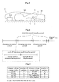
- Fig. 2 is a schematic view showing a situation in time of charging by the charging system in the embodiment.
- the charging system in the embodiment includes a storage device 1 wholly embedded, as molded in a silicone resin or the like together with a cardiac pacemaker 3 acting as an artificial organ, for example, in the body of a user M of the pacemaker 3, and a feeding device formed separately from this storage device 1 and disposed as a whole outside the body of the user M carrying the pacemaker 3.
- the pacemaker 3 while receiving a supply of driving electric power from the storage device 1, causes the heart of the user M to continue beating regularly by directly applying an electrical pulse to and stimulating the heart.
- the storage device 1 includes a power receiving coil (power receiving coil means) 4 acting as a secondary side coil in a pair of power transfer coils, a full wave rectification bridge (rectifying means) 5 for rectifying and outputting an AC received by the power receiving coil 4, and an electric double layer capacitor (storage means) 6 chargeable with the output from the full wave rectification bridge 5 to store pacemaker driving electric power.
- a ripple removing capacitor 7 and a reverse current preventing diode 8 are arranged between the full wave rectification bridge 5 and electric double layer capacitor (EDLC) 6.
- the feeding device 2 includes a power transmitting coil (power transmitting coil means) 9 acting as a primary side coil in the pair of power transfer coils, an AC oscillator (AC output means) 10 for outputting an AC with a frequency of about 100kHz to 2GHz to this power transmitting coil 9.
- the power transmitting coil 9 is connected to a main body case 2A by a cable 9A to be freely movable.
- the power receiving coil 4 and power transmitting coil 9 usually have a diameter of about 20-50mm, the power transmitting coil 9 being slightly larger.
- the charging system is started after setting the power transmitting coil 9 of the feeding device 2 outside the body to a position opposed to the power receiving coil 4 of the storage device 1 inside the body so that the power receiving and power transmitting coils 4 and 9 may transfer power by electromagnetic coupling, electromagnetic induction or electromagnetic wave. Then, the AC required for the charging outputted from the AC oscillator 10 of the feeding device 2 is transmitted from the power transmitting coil 9 outside the body to the storage device 1 inside the body. The AC transmitted from the power transmitting coil 9 is received by the power receiving coil 4 inside the body, rectified by the full wave rectification bridge 5, and then fed to the electric double layer capacitor 6.
- pacemaker driving power is stored by the output from the full wave rectification bridge 5.
- the storage device 1 includes a voltage monitor circuit (charge status detecting means) 11 for detecting a charge voltage indicative of a charge status of the electric double layer capacitor 6.
- This voltage monitor circuit 11 is arranged to output the detected charge voltage of the electric double layer capacitor 6 to a secondary side control circuit 12, and to stop the charging automatically when the charge voltage of the electric double layer capacitor 6 reaches 2.3V which is an operating voltage of the pacemaker 3.
- the electric double layer capacitor 6 has a withstand voltage of 2.5V, and therefore an upper limit of the charge voltage of the electric double layer capacitor 6 is set to 2.3V which is a voltage below the withstand voltage.
- the secondary side control circuit 12 acts as charge status transmitting means for cooperating with a resonance circuit 13 to transmit outside the body a charge status corresponding to the charge voltage detected by the voltage monitor circuit 11.
- the resonance circuit 13 is formed of the power receiving coil 4, and a capacitor 13A and a digital variable resistor 13B connected in parallel therewith.
- the power transfer action of the power receiving and power transmitting coils 4 and 9, essentially, is performed under resonant conditions.
- the digital variable resistor 13B is a resistor having a resistance discretely (stepwise) changeable by a digital signal outputted from the secondary side control circuit 12.
- a resonant condition caused by the resonance circuit 13 is changeable stepwise, with a change of the digital variable resistor 13B, from a full resonant condition to a virtually absolutely non-resonant condition.
- This change in the resonant condition on the secondary side by the resonance circuit 13 is transmitted from the power receiving coil 4 to the primary side through the power transmitting coil 9.
- a voltage at opposite ends of the power transmitting coil 9 varies according to levels of the resonant condition, and this is used to transmit the charge status of the electric double layer capacitor 6 outside the body.
- a detection result communicating period is set after every fixed charging period.
- the first half of the detection result communicating period is set as a charge status communicating period.
- a digital signal is transmitted from the secondary side control circuit 12 to the variable resistor 13B to set a resistance to the digital variable resistor 13B to make the resonant condition by the resonance circuit 13 the full resonant condition over the entire period.
- charging power is transmitted efficiently with the resonant condition by the resonance circuit 13 in the full resonant condition over the entire period.
- the charge voltage range (0V - 2.3V) of the electric double layer capacitor 6 is divided into eight stages corresponding to the numbers of pulses 1 to 8, and a charge status is transmitted outside the body from inside the body by transmitting to the feeding device 2 the number of pulses corresponding to the charge voltage of the electric double layer capacitor 6 detected by the voltage monitor circuit 11 during one charge status communicating period.
- a circuit operation in which a digital signal is transmitted from the secondary side control circuit 12 to the digital variable resistor 13B so that the variable resistor 13B has a resistance to make the resonant condition by the resonance circuit 13 the absolutely non-resonant condition only for a predetermined short period of time, is repeated so that the number of pulses corresponding to the charge voltage may be outputted.
- the charge status of the electric double layer capacitor 6 transmitted outside the body from inside the body in the form of pulse as described above, is detected based on a voltage change at the opposite ends of the power transmitting coil 9 of the feeding device 2 as described next. That is, a voltage at the opposite ends of the power transmitting coil 9 is detected by a voltage smoothing circuit 14 including a rectifier diode 14A, a resistance 14B and a capacitor 14C, and outputted to a primary side control circuit 15.
- the primary side control circuit 15 by detecting output changes of the voltage smoothing circuit 14, determines a charge status (number of pulses) of the storage device 1 during one charge status communicating period.
- a pulse train transmitted from the storage device is smoothed, and the number of pulses is detected from its voltage value. However, the number of pulses may be counted directly.
- the primary side control circuit 15 When, as shown in Fig. 5, for example, during one charge status communicating period, switching to the absolutely non-resonant condition only for a fixed period of the resonant condition by the resonance circuit 13 is repeated four times, the primary side control circuit 15 counts four pulses as shown in Fig. 6. And when the primary side control circuit 15 counts eight pulses during one charge status communicating period, it is detected that the charge voltage of the electric double layer capacitor 6 has reached 2.3V, i.e. reached a full charge status.
- the power transmitting coil 9, voltage smoothing circuit 14 and primary side control circuit 15 constitute a charge status receiving means for receiving a charge status of the electric double layer capacitor 6 transmitted outside the body from inside the body.
- the feeding device 2 includes a charge status display panel (charge status informing means) 16 disposed downstream of the primary side control circuit 15 for displaying, in real time, a charge status of the electric double layer capacitor 6.
- a charge status of the electric double layer capacitor 6 is notified by lighting the number of light emitting diodes 16a corresponding to the number of pulses counted by the primary side control circuit 15.
- the storage device 1 detects an amount of displacement between the power receiving and power transmitting coils 4 and 9 (amount of coil displacement), and transmits the detected amount of coil displacement outside the body through the power receiving and power transmitting coils 4 and 9 by varying the resonant condition by the resonance circuit 13 according the detected amount of coil displacement, as when transmitting the charge status of the electric double layer capacitor 6 outside the body.
- the transmission efficiency of charging power lowers in proportion to the amount of coil displacement between the power receiving and power transmitting coils 4 and 9, resulting in an extended charging time. For this reason, the displacement between the power receiving coil 4 and power transmitting coil 9 is detected and checked outside the body.
- the amount of coil displacement between the power receiving and power transmitting coils 4 and 9 and the power transmission efficiency between the power receiving and power transmitting coils 4 and 9 are in inversely proportional relationship.
- the larger amount of coil displacement results in the lower AC voltage produced at the opposite ends of the power receiving coil 4. That is, the voltage at the opposite ends of the power receiving coil 4 is inversely proportional to the amount of coil displacement.
- the voltage at the opposite ends of the power receiving coil 4 corresponding to the amount of coil displacement is smoothed by a voltage smoothing circuit 17 including a rectifier diode 17A, a resistance 17B and a capacitor 17C, and its voltage value is detected by the secondary side control circuit 12.
- the voltage smoothing circuit 17 and secondary side control circuit 12 correspond to the amount of coil displacement detecting means in this invention.
- the output voltage range of the voltage smoothing circuit 17 is divided beforehand into five stages, for example.
- the respective output voltage divisions have, assigned thereto in order from lowest voltage, five-stage resonance levels 1 to 5 set to rise successively stage by stage from the absolutely non-resonant condition.
- the resonance levels 1 to 5 are set so that voltage changes at the opposite ends of the power transmitting coil 9 occurring with changes between resonance level 5 and absolutely non-resonant condition are approximately half the voltage changes at the opposite ends of the power transmitting coil 9 occurring with the changes between the full resonant condition and absolutely non-resonant condition.
- the second half of the detection result communicating period is set as an amount of coil displacement communicating period.
- the secondary side control circuit 12 recognizes a voltage division of the amount of coil displacement corresponding to a voltage detected by the voltage smoothing circuit 17.
- a digital signal is transmitted from the secondary side control circuit 12 to the digital variable resistor 13B so that the resonant condition by the resonance circuit 13 may be the resonant condition corresponding to the recognized voltage division.
- the resonance by the resonance circuit 13 is made the resonant condition 3.
- a phenomenon of a change in the voltage at the opposite ends of the power transmitting coil 9 also takes place in the feeding device 2 which is the primary side. Then, the feeding device 2 uses this phenomenon, and detects an amount of coil displacement between the power receiving and power transmitting coils 4 and 9 transmitted outside the body. The larger the amount of coil displacement is, the farther away the resonant condition of the resonance circuit 13 is from the full resonant condition. Therefore, the voltage at the opposite ends of the power transmitting coil 9 lowers in proportion to the amount of coil displacement.
- the voltage smoothing circuit 14 smoothes the voltage at the opposite ends of the power transmitting coil 9, and the primary side control circuit 15 checks its voltage value to detect the amount of coil displacement.
- the output voltage range of the voltage smoothing circuit 14 is divided into five stages to correspond to the divisions of the output voltage range of the voltage smoothing circuit 17 (i.e. amount of coil displacement Q).
- the primary side control circuit 15 checks a value of the voltage outputted from the voltage smoothing circuit 14, recognizes a division corresponding thereto, and detects an amount of coil displacement.
- the primary side control circuit 15 checks whether a change in the output voltage of the voltage smoothing circuit 14 is the same as or half a voltage change occurring with a change between the full resonant condition and absolutely non-resonant condition. If it is the same, it is recognized and processed as the communication of a charge status. If it is the half, it is recognized and processed as the communication of an amount of coil displacement. Thus, an arrangement is provided to avoid confusion.
- the feeding device 2 includes an amount of coil displacement display panel (amount of coil displacement informing means) 18 disposed downstream of the primary side control circuit 15 for displaying an amount of coil displacement between the power receiving and power transmitting coils 4 and 9. An amount of coil displacement is notified by lighting the number of light emitting diodes 18a corresponding to the amount of coil displacement detected by the primary side control circuit 15.
- the light emitting diodes 18a correspond to the display means of this invention.
- Fig. 9 is a flow chart showing a progress of charging by the charging system in the embodiment.
- a charging experiment has been conducted with a 10mm thick piece of meat placed between the power receiving and power transmitting coils 4 and 9.
- the capacity of the electric double layer capacitor 6 is IF.
- Fig. 10 shows variations with time of the charge voltage of the electric double layer capacitor 6 in the charging experiment. As shown in Fig. 10, the electric double layer capacitor 6 reached the full charge status of 2.3V 440 seconds from a start of charging.
- a charging experiment has been conducted in the same way noted above except that a mere space is left, with no meat piece placed, between the power receiving and power transmitting coils 4 and 9.
- Fig. 11 shows variations with time of the charge voltage of the electric double layer capacitor 6 in this charging experiment. As shown in Fig. 11, the electric double layer capacitor 6 reached the full charge status of 2.3V 228 seconds from a start of charging.
- the AC required for charging of the storage device 1 in the body may be transmitted from outside the body in the form of electromagnetic coupling, electromagnetic induction or electromagnetic wave.
- the electric double layer capacitor 6 may be charged in a contactless mode from outside the body, without incising the body, while the storage device 1 remains embedded in the body. Charging may be carried out reliably since the operator can check the charge status of the electric double layer capacitor 6 of the storage device 1 during a charging operation. In the case of the charging system in the embodiment, since the operator can know an amount of coil displacement between the power receiving and power transmitting coils 4 and 9, charging may be carried out efficiently by correcting the coil displacement between the power receiving and power transmitting coils 4 and 9.
- the storage device 1 detects a direction of displacement occurring between the power receiving coil 4 and power transmitting coil 9 (direction of coil displacement), and transmits it outside the body from inside the body.
- the feeding device 2 detects and informs the direction of coil displacement transmitted outside the body from inside the body. Since the other aspects are the same as in the preceding embodiment, common points will not be described and only different points will be described.
- the charging system has four direction detecting coils 19A-19D arranged equidistantly at 90° intervals in the circumferential direction around the power receiving coil 4, and a voltage detecting and coil identifying circuit 20 for detecting voltages produced on the direction detecting coils 19A-19D as the charging electric power is transmitted from the power transmitting coil 9, comparing levels of the detected voltages of the direction detecting coils 19A-19D to identify a direction detecting coil located in a direction of displacement of the power transmitting coil 9, and outputting it as a direction of coil displacement to the secondary side control circuit 12.
- the direction detecting coils 19A-19D and voltage detecting and coil identifying circuit 20 constitute the direction of coil displacement detecting means.
- numbers of pulses 10 to 13 are assigned to the respective direction detecting coils 19A-19D.
- a coil outputted from the voltage detecting and coil identifying circuit 20 is transmitted outside the body from inside the body in a form converted into the number of pulses, as in the case of communicating the charge status of the electric double layer capacitor 6 outside the body.
- the voltage smoothing circuit 14 and primary side control circuit 15 count the number of pulses, detect a direction of coil displacement and report it on a direction of coil displacement display panel (not shown), as in the case of detecting the charge status of the electric double layer capacitor 6 transmitted outside the body.
- the coil displacement between the power receiving and power transmitting coils 4 and 9 may be corrected easily.
- a contactless charging system for an artificial organ and a storage device and a feeding device for use with this system, according to this invention, are suitable for use with artificial organs such as a cardiac pacemaker, artificial heart, artificial pancreas, artificial urinary bladder and so on.
Landscapes
- Engineering & Computer Science (AREA)
- Computer Networks & Wireless Communication (AREA)
- Power Engineering (AREA)
- Health & Medical Sciences (AREA)
- Animal Behavior & Ethology (AREA)
- Nuclear Medicine, Radiotherapy & Molecular Imaging (AREA)
- Radiology & Medical Imaging (AREA)
- Life Sciences & Earth Sciences (AREA)
- Biomedical Technology (AREA)
- General Health & Medical Sciences (AREA)
- Public Health (AREA)
- Veterinary Medicine (AREA)
- Charge And Discharge Circuits For Batteries Or The Like (AREA)
- Electrotherapy Devices (AREA)
- Secondary Cells (AREA)
- External Artificial Organs (AREA)
Abstract
Description
Claims (18)
- A contactless charging system for an artificial organ characterized by comprising:(A) a storage device embedded as a whole in a body along with the artificial organ, and including power receiving coil means acting as a secondary side coil in a pair of coil means for transferring power, rectifying means for rectifying and outputting an AC received by the power receiving coil means, storage means for storing output from the rectifying means as electric power for driving the artificial organ, charge status detecting means for detect a charge status of the storage means, and charge status transmitting means for transmitting outside the body the charge status detected by the charge status detecting means; and(B) a feeding device provided separately from the storage device and disposed as a whole outside the body, and including power transmitting coil means acting as a primary side coil in said pair of coil means, AC output means for outputting the AC to the power transmitting coil means, charge status receiving means for receiving the charge status transmitted outside the body from said charge status transmitting means, and charge status informing means for informing the charge status received by the charge status receiving means.
- A contactless charging system for an artificial organ as defined in claim 1, wherein:at least one of the storage device and the feeding device includes amount of coil displacement detecting means for detecting an amount of coil displacement as an extent of a displacement occurring between the power receiving coil means and the power transmitting coil means, and the feeding device includes amount of coil displacement informing means for informing the amount of coil displacement detected by the amount of coil displacement detecting means.
- A contactless charging system for an artificial organ as defined in claim 2, wherein:the amount of coil displacement detecting means of said storage device includes a smoothing circuit for smoothing a voltage at opposite ends of said power receiving coil detecting means, and a secondary side control circuit for determining the amount of coil displacement based on a smoothed voltage value.
- A contactless charging system for an artificial organ as defined in claim 2, wherein:the amount of coil displacement detecting means of said feeding device includes a smoothing circuit for smoothing a voltage at opposite ends of said power transmitting coil detecting means, and a primary side control circuit for determining the amount of coil displacement based on a smoothed voltage value.
- A contactless charging system for an artificial organ as defined in claim 2, wherein:the amount of coil displacement detecting means is disposed in the storage device, the amount of coil displacement detected being transmitted outside the body along with the charge status by said charge status transmitting means.
- A contactless charging system for an artificial organ as defined in claim 5, comprising:display means for displaying the amount of coil displacement and the charge status transmitted outside the body by said charge status transmitting means.
- A contactless charging system for an artificial organ as defined in claim 1, wherein:at least one of the storage device and the feeding device includes direction of coil displacement detecting means for detecting a direction of coil displacement as an extent of a displacement occurring between the power receiving coil means and the power transmitting coil means, and the feeding device includes direction of coil displacement informing means for informing the direction of coil displacement detected by the direction of coil displacement detecting means.
- A contactless charging system for an artificial organ as defined in claim 7, wherein:the direction of coil displacement detecting means of said storage device includes a plurality of direction detecting coils arranged at predetermined intervals around said power receiving coil means, and a secondary side control circuit for determining the direction of coil displacement based on voltages values detected from the plurality of direction detecting coils.
- A contactless charging system for an artificial organ as defined in claim 7, wherein:the direction of coil displacement detecting means of said storage device includes a plurality of direction detecting coils arranged at predetermined intervals around said power receiving coil means, and a primary side control circuit for determining the direction of coil displacement based on voltages values detected from the plurality of direction detecting coils.
- A contactless charging system for an artificial organ as defined in claim 7, wherein:the direction of coil displacement detecting means of said storage device includes a plurality of divided power receiving coil means arranged annularly, and a secondary side control circuit for determining the direction of coil displacement based on voltages values detected from the respective power receiving coil means.
- A contactless charging system for an artificial organ as defined in claim 7, wherein:the direction of coil displacement detecting means of said storage device includes a plurality of divided power receiving coil means arranged annularly, and a primary side control circuit for determining the direction of coil displacement based on voltages values detected from the respective power receiving coil means.
- A contactless charging system for an artificial organ as defined in claim 7, wherein:the direction of coil displacement detecting means is disposed in the storage device, the direction of coil displacement detected being transmitted outside the body along with the charge status by said charge status transmitting means.
- A contactless charging system for an artificial organ as defined in claim 12, comprising:display means for displaying the direction of coil displacement and the charge status transmitted outside the body by said charge status transmitting means.
- A contactless charging system for an artificial organ as defined in claim 1, wherein:the charge status transmitting means of the storage device is arranged to transmit a result of detection of the charge status outside the body through power receiving coil means power transmitting coil means acting as the pair of coil means for transferring power.
- A contactless charging system for an artificial organ as defined in claim 1, wherein:the storage means of said storage device is a rechargeable battery.
- A contactless charging system for an artificial organ as defined in claim 1, wherein:the storage means of said storage device is an electric double layer capacitor.
- A storage device for use with a contactless charging system for an artificial organ characterized in that:the storage device is the storage device set forth in claim 1.
- A feeding device for use with a contactless charging system for an artificial organ characterized in that:the feeding device is the feeding device set forth in claim 1.
Applications Claiming Priority (3)
| Application Number | Priority Date | Filing Date | Title |
|---|---|---|---|
| JP2002148908 | 2002-05-23 | ||
| JP2002148908A JP3731881B2 (en) | 2002-05-23 | 2002-05-23 | Non-invasive charging system for artificial organs, power storage device used in this system, and power supply device |
| PCT/JP2003/006430 WO2003100942A1 (en) | 2002-05-23 | 2003-05-22 | Non-intrusion type charging system for artificial organ, capacitor and power supplying device used in the system |
Publications (2)
| Publication Number | Publication Date |
|---|---|
| EP1513241A1 true EP1513241A1 (en) | 2005-03-09 |
| EP1513241A4 EP1513241A4 (en) | 2008-10-01 |
Family
ID=29561197
Family Applications (1)
| Application Number | Title | Priority Date | Filing Date |
|---|---|---|---|
| EP03730594A Withdrawn EP1513241A4 (en) | 2002-05-23 | 2003-05-22 | NON-INTRUSIVE CHARGE SYSTEM FOR ARTIFICIAL OR CAPACITOR AND POWER SUPPLY DEVICE USED THEREIN |
Country Status (6)
| Country | Link |
|---|---|
| US (1) | US8000800B2 (en) |
| EP (1) | EP1513241A4 (en) |
| JP (1) | JP3731881B2 (en) |
| AU (1) | AU2003242408B2 (en) |
| CA (1) | CA2486970A1 (en) |
| WO (1) | WO2003100942A1 (en) |
Cited By (28)
| Publication number | Priority date | Publication date | Assignee | Title |
|---|---|---|---|---|
| WO2009051538A1 (en) * | 2007-10-16 | 2009-04-23 | Milux Holding Sa | A method and apparatus for supplying energy to a medical device |
| WO2010059097A1 (en) * | 2008-11-21 | 2010-05-27 | Milux Holding S.A. | System, method and apparatus f or supplying energy to an implantable medical device |
| EP1806647A3 (en) * | 2005-12-12 | 2012-04-04 | Wacom Co., Ltd. | Position input device and computer system |
| CN101462633B (en) * | 2007-12-18 | 2012-06-27 | 大福股份有限公司 | Article storage apparatus |
| US8373683B2 (en) | 2005-12-12 | 2013-02-12 | Wacom Co., Ltd | Position input device and computer system |
| US8463395B2 (en) | 2007-10-16 | 2013-06-11 | Teslux Holding Sa | Method and apparatus for supplying energy to a medical device |
| EP2878060A4 (en) * | 2012-07-27 | 2016-04-06 | Thoratec Corp | WIRELESS BATTERY CHARGING |
| US9583874B2 (en) | 2014-10-06 | 2017-02-28 | Thoratec Corporation | Multiaxial connector for implantable devices |
| US9592397B2 (en) | 2012-07-27 | 2017-03-14 | Thoratec Corporation | Thermal management for implantable wireless power transfer systems |
| US9680310B2 (en) | 2013-03-15 | 2017-06-13 | Thoratec Corporation | Integrated implantable TETS housing including fins and coil loops |
| US9805863B2 (en) | 2012-07-27 | 2017-10-31 | Thoratec Corporation | Magnetic power transmission utilizing phased transmitter coil arrays and phased receiver coil arrays |
| US9825471B2 (en) | 2012-07-27 | 2017-11-21 | Thoratec Corporation | Resonant power transfer systems with protective algorithm |
| US9855437B2 (en) | 2013-11-11 | 2018-01-02 | Tc1 Llc | Hinged resonant power transfer coil |
| US9997928B2 (en) | 2012-07-27 | 2018-06-12 | Tc1 Llc | Self-tuning resonant power transfer systems |
| US10148126B2 (en) | 2015-08-31 | 2018-12-04 | Tc1 Llc | Wireless energy transfer system and wearables |
| US10177604B2 (en) | 2015-10-07 | 2019-01-08 | Tc1 Llc | Resonant power transfer systems having efficiency optimization based on receiver impedance |
| US10186760B2 (en) | 2014-09-22 | 2019-01-22 | Tc1 Llc | Antenna designs for communication between a wirelessly powered implant to an external device outside the body |
| US10251987B2 (en) | 2012-07-27 | 2019-04-09 | Tc1 Llc | Resonant power transmission coils and systems |
| US10291067B2 (en) | 2012-07-27 | 2019-05-14 | Tc1 Llc | Computer modeling for resonant power transfer systems |
| US10373756B2 (en) | 2013-03-15 | 2019-08-06 | Tc1 Llc | Malleable TETs coil with improved anatomical fit |
| US10383990B2 (en) | 2012-07-27 | 2019-08-20 | Tc1 Llc | Variable capacitor for resonant power transfer systems |
| US10525181B2 (en) | 2012-07-27 | 2020-01-07 | Tc1 Llc | Resonant power transfer system and method of estimating system state |
| US10615642B2 (en) | 2013-11-11 | 2020-04-07 | Tc1 Llc | Resonant power transfer systems with communications |
| US10610692B2 (en) | 2014-03-06 | 2020-04-07 | Tc1 Llc | Electrical connectors for implantable devices |
| US10695476B2 (en) | 2013-11-11 | 2020-06-30 | Tc1 Llc | Resonant power transfer systems with communications |
| US10770923B2 (en) | 2018-01-04 | 2020-09-08 | Tc1 Llc | Systems and methods for elastic wireless power transmission devices |
| US10898292B2 (en) | 2016-09-21 | 2021-01-26 | Tc1 Llc | Systems and methods for locating implanted wireless power transmission devices |
| US11197990B2 (en) | 2017-01-18 | 2021-12-14 | Tc1 Llc | Systems and methods for transcutaneous power transfer using microneedles |
Families Citing this family (71)
| Publication number | Priority date | Publication date | Assignee | Title |
|---|---|---|---|---|
| WO2005070494A1 (en) | 2004-01-22 | 2005-08-04 | Rehabtronics Inc. | Method of routing electrical current to bodily tissues via implanted passive conductors |
| US20100016929A1 (en) * | 2004-01-22 | 2010-01-21 | Arthur Prochazka | Method and system for controlled nerve ablation |
| DE102004048864A1 (en) | 2004-10-07 | 2006-04-13 | Roche Diagnostics Gmbh | Analytical test element with wireless data transmission |
| US20060085051A1 (en) * | 2004-10-19 | 2006-04-20 | Fritsch Michael H | Electrical implants |
| JP5068660B2 (en) * | 2004-10-29 | 2012-11-07 | メドトロニック,インコーポレイテッド | How to charge a lithium-ion battery |
| US8483820B2 (en) * | 2006-10-05 | 2013-07-09 | Bioness Inc. | System and method for percutaneous delivery of electrical stimulation to a target body tissue |
| JP5121307B2 (en) * | 2007-05-28 | 2013-01-16 | ソニーモバイルコミュニケーションズ株式会社 | Non-contact power transmission coil unit, portable terminal, power transmission device, and non-contact power transmission system |
| US9757554B2 (en) | 2007-08-23 | 2017-09-12 | Bioness Inc. | System for transmitting electrical current to a bodily tissue |
| US8738137B2 (en) | 2007-08-23 | 2014-05-27 | Bioness Inc. | System for transmitting electrical current to a bodily tissue |
| CA2697381A1 (en) * | 2007-08-23 | 2009-02-26 | Bioness, Inc. | System for transmitting electrical current to a bodily tissue |
| WO2009041058A1 (en) * | 2007-09-27 | 2009-04-02 | Panasonic Corporation | Electronic device, recharger and recharging system |
| KR101437975B1 (en) * | 2007-12-06 | 2014-09-05 | 엘지전자 주식회사 | Solid state charging device with charge state display function and charging method thereof |
| US20090157113A1 (en) * | 2007-12-18 | 2009-06-18 | Ethicon Endo-Surgery, Inc. | Wearable elements for implantable restriction systems |
| US8759076B2 (en) * | 2008-02-01 | 2014-06-24 | Patrick Glenn Gulak | Method and apparatus for detecting an electric field fluctuation associated with the permeabilization of a bacterial cell wall |
| JP5141285B2 (en) * | 2008-02-14 | 2013-02-13 | 日本電気株式会社 | Non-contact charger |
| JP5075683B2 (en) * | 2008-03-05 | 2012-11-21 | 富士フイルム株式会社 | Non-contact charging device and non-contact charging method |
| JP4893689B2 (en) * | 2008-05-09 | 2012-03-07 | セイコーエプソン株式会社 | Power receiving device, electronic device, non-contact power transmission system, and power transmitting device |
| US20090326602A1 (en) * | 2008-06-27 | 2009-12-31 | Arkady Glukhovsky | Treatment of indications using electrical stimulation |
| JP2010051089A (en) * | 2008-08-21 | 2010-03-04 | Fujitsu Ltd | Non-contacting power transmission system |
| US8473066B2 (en) | 2009-07-06 | 2013-06-25 | Boston Scientific Neuromodulation Company | External charger for a medical implantable device using field sensing coils to improve coupling |
| US8311638B2 (en) | 2009-10-15 | 2012-11-13 | Boston Scientific Neuromodulation Corporation | External charger for a medical implantable device using field inducing coils to improve coupling |
| JP5563346B2 (en) * | 2010-03-29 | 2014-07-30 | パナソニック株式会社 | Power transmission device and waveform monitor circuit used therefor |
| JP5476211B2 (en) * | 2010-05-19 | 2014-04-23 | Necトーキン株式会社 | Power transmission device, power receiving device, non-contact power transmission and communication system |
| US20120104997A1 (en) * | 2010-11-01 | 2012-05-03 | Qualcomm Incorporated | Wireless charging device |
| JP5824801B2 (en) * | 2010-12-06 | 2015-12-02 | 株式会社ニデック | Biological tissue stimulator |
| JP5793963B2 (en) | 2011-05-27 | 2015-10-14 | 日産自動車株式会社 | Non-contact power feeding device |
| JP5879748B2 (en) * | 2011-05-27 | 2016-03-08 | 日産自動車株式会社 | Non-contact power supply device, vehicle and non-contact power supply system |
| US8552595B2 (en) * | 2011-05-31 | 2013-10-08 | General Electric Company | System and method for contactless power transfer in portable image detectors |
| US8700175B2 (en) | 2011-07-19 | 2014-04-15 | Greatbatch Ltd. | Devices and methods for visually indicating the alignment of a transcutaneous energy transfer device over an implanted medical device |
| US9446254B2 (en) | 2011-10-13 | 2016-09-20 | Boston Scientific Neuromodulation Corporation | Charger alignment in an implantable medical device system employing reflected impedance modulation |
| US9314642B2 (en) | 2011-10-13 | 2016-04-19 | Boston Scientific Neuromodulation Corporation | Closed loop charger for an implantable medical device system employing reflected impedance modulation |
| US8666504B2 (en) * | 2011-10-24 | 2014-03-04 | Boston Scientific Neuromodulation Corporation | Communication and charging circuitry for a single-coil implantable medical device |
| US9079043B2 (en) * | 2011-11-21 | 2015-07-14 | Thoratec Corporation | Transcutaneous power transmission utilizing non-planar resonators |
| JP6060516B2 (en) * | 2011-11-30 | 2017-01-18 | ソニー株式会社 | Electronic equipment and power supply system |
| EP2643053B1 (en) * | 2011-12-16 | 2016-08-24 | Abiomed, Inc. | Automatic power regulation for transcutaneous energy transfer charging system |
| JP2013192391A (en) * | 2012-03-14 | 2013-09-26 | Sony Corp | Detecting apparatus, power receiving apparatus, power transmitting apparatus, and contactless power supply system |
| WO2014036184A2 (en) * | 2012-08-29 | 2014-03-06 | University Of Southern California | Monitoring and controlling charge rate and level of battery in inductively-charged pulse generating device |
| US9872997B2 (en) | 2013-03-15 | 2018-01-23 | Globus Medical, Inc. | Spinal cord stimulator system |
| AU2014232252B2 (en) | 2013-03-15 | 2018-01-18 | Alfred E. Mann Foundation For Scientific Research | Current sensing multiple output current stimulators with fast turn on time |
| US9887574B2 (en) | 2013-03-15 | 2018-02-06 | Globus Medical, Inc. | Spinal cord stimulator system |
| US9878170B2 (en) | 2013-03-15 | 2018-01-30 | Globus Medical, Inc. | Spinal cord stimulator system |
| US9440076B2 (en) | 2013-03-15 | 2016-09-13 | Globus Medical, Inc. | Spinal cord stimulator system |
| US8933585B2 (en) | 2013-04-30 | 2015-01-13 | Utilidata, Inc. | Metering optimal sampling |
| JP6173057B2 (en) * | 2013-06-11 | 2017-08-02 | キヤノン株式会社 | Power supply apparatus, power supply method, program, and recording medium |
| CA3075310C (en) | 2013-07-29 | 2022-04-05 | Alfred E. Mann Foundation For Scientific Research | Microprocessor controlled class e driver |
| US9339660B2 (en) | 2013-10-04 | 2016-05-17 | Boston Scientific Neuromodulation Corporation | Implantable medical device with one or more magnetic field sensors to assist with external charger alignment |
| JP2016007230A (en) * | 2014-06-20 | 2016-01-18 | 国立大学法人 東京大学 | Transmission coil for transdermal wireless power transmission system |
| CA3208375A1 (en) | 2014-08-15 | 2016-02-18 | Axonics, Inc. | External pulse generator device and associated methods for trial nerve stimulation |
| WO2016025915A1 (en) | 2014-08-15 | 2016-02-18 | Axonics Modulation Technologies, Inc. | Integrated electromyographic clinician programmer for use with an implantable neurostimulator |
| EP3180070B1 (en) | 2014-08-15 | 2021-04-14 | Axonics Modulation Technologies, Inc. | Implantable lead affixation structure for nerve stimulation to alleviate bladder dysfunction and other indications |
| CA2958199C (en) | 2014-08-15 | 2023-03-07 | Axonics Modulation Technologies, Inc. | Electromyographic lead positioning and stimulation titration in a nerve stimulation system for treatment of overactive bladder |
| CA2957967C (en) | 2014-08-15 | 2018-11-27 | Axonics Modulation Technologies, Inc. | Systems and methods for neurostimulation electrode configurations based on neural localization |
| CA2973192C (en) | 2015-01-09 | 2023-04-04 | Axonics Modulation Technologies, Inc. | Improved antenna and methods of use for an implantable nerve stimulator |
| JP6805153B2 (en) | 2015-01-09 | 2020-12-23 | アクソニクス モジュレーション テクノロジーズ インコーポレイテッド | How to use with patient remote devices and associated neurostimulation systems |
| JP6751718B2 (en) | 2015-01-09 | 2020-09-09 | アクソニクス モジュレーション テクノロジーズ インコーポレイテッド | Mounting devices and related methods for use with neurostimulation charging devices |
| JP6946261B2 (en) | 2015-07-10 | 2021-10-06 | アクソニクス インコーポレイテッド | Implantable nerve stimulators and methods with internal electronics without ASICs |
| US10603500B2 (en) | 2016-01-29 | 2020-03-31 | Axonics Modulation Technologies, Inc. | Methods and systems for frequency adjustment to optimize charging of implantable neurostimulator |
| EP3413970B1 (en) | 2016-02-12 | 2021-06-30 | Axonics, Inc. | External pulse generator device for trial nerve stimulation |
| JP6692210B2 (en) * | 2016-05-16 | 2020-05-13 | セイコーインスツル株式会社 | Electronic equipment and wireless power supply system |
| US11139666B2 (en) | 2017-10-24 | 2021-10-05 | Stryker Corporation | Energy harvesting and propulsion assistance techniques for a patient support apparatus |
| US11394252B2 (en) | 2017-10-24 | 2022-07-19 | Stryker Corporation | Power transfer system with patient support apparatus and power transfer device to transfer power to the patient support apparatus |
| US10797524B2 (en) | 2017-10-24 | 2020-10-06 | Stryker Corporation | Techniques for power transfer through wheels of a patient support apparatus |
| US11389357B2 (en) | 2017-10-24 | 2022-07-19 | Stryker Corporation | Energy storage device management for a patient support apparatus |
| US10910888B2 (en) | 2017-10-24 | 2021-02-02 | Stryker Corporation | Power transfer system with patient transport apparatus and power transfer device to transfer power to the patient transport apparatus |
| US11110283B2 (en) | 2018-02-22 | 2021-09-07 | Axonics, Inc. | Neurostimulation leads for trial nerve stimulation and methods of use |
| WO2020185902A1 (en) | 2019-03-11 | 2020-09-17 | Axonics Modulation Technologies, Inc. | Charging device with off-center coil |
| US11439829B2 (en) | 2019-05-24 | 2022-09-13 | Axonics, Inc. | Clinician programmer methods and systems for maintaining target operating temperatures |
| US11848090B2 (en) | 2019-05-24 | 2023-12-19 | Axonics, Inc. | Trainer for a neurostimulator programmer and associated methods of use with a neurostimulation system |
| US12420103B1 (en) | 2020-08-20 | 2025-09-23 | Axonics, Inc. | Neurostimulation leads with reduced current leakage |
| US12537397B2 (en) * | 2022-05-17 | 2026-01-27 | Koninklijke Philips N.V. | Wireless power transfer |
| DE102024114434A1 (en) * | 2023-05-31 | 2024-12-05 | Drägerwerk AG & Co. KGaA | IDENTIFICATION OF THE LOCATION OF A PHYSIOLOGICAL PATIENT MONITOR |
Family Cites Families (20)
| Publication number | Priority date | Publication date | Assignee | Title |
|---|---|---|---|---|
| US3942535A (en) * | 1973-09-27 | 1976-03-09 | G. D. Searle & Co. | Rechargeable tissue stimulating system |
| JPS5060085A (en) * | 1973-09-27 | 1975-05-23 | ||
| DE2616297C2 (en) * | 1975-04-17 | 1984-10-31 | The Johns Hopkins University, Baltimore, Md. | Rechargeable electrical body tissue stimulator |
| JPS6124284Y2 (en) * | 1981-04-08 | 1986-07-21 | ||
| US5314453A (en) * | 1991-12-06 | 1994-05-24 | Spinal Cord Society | Position sensitive power transfer antenna |
| JP3119321B2 (en) * | 1992-09-30 | 2000-12-18 | 東京瓦斯株式会社 | Detection method of target points in buried pipes |
| US5383912A (en) * | 1993-05-05 | 1995-01-24 | Intermedics, Inc. | Apparatus for high speed data communication between an external medical device and an implantable medical device |
| US5425382A (en) * | 1993-09-14 | 1995-06-20 | University Of Washington | Apparatus and method for locating a medical tube in the body of a patient |
| JPH0831339B2 (en) * | 1993-11-08 | 1996-03-27 | 株式会社竹田技術研究所 | Charger for cordless equipment using electric double layer capacitor |
| US5591217A (en) * | 1995-01-04 | 1997-01-07 | Plexus, Inc. | Implantable stimulator with replenishable, high value capacitive power source and method therefor |
| JPH08257144A (en) * | 1995-03-22 | 1996-10-08 | Nec Corp | Electrical stimulator |
| US5690693A (en) * | 1995-06-07 | 1997-11-25 | Sulzer Intermedics Inc. | Transcutaneous energy transmission circuit for implantable medical device |
| FR2751149B1 (en) * | 1996-07-12 | 1998-09-18 | Inside Technologies | DEVICE FOR TRANSMITTING AND RECEIVING DIGITAL DATA BY ELECTROMAGNETIC INDUCTION AND INDUCTIVE COUPLING |
| US6695885B2 (en) * | 1997-02-26 | 2004-02-24 | Alfred E. Mann Foundation For Scientific Research | Method and apparatus for coupling an implantable stimulator/sensor to a prosthetic device |
| US6138681A (en) * | 1997-10-13 | 2000-10-31 | Light Sciences Limited Partnership | Alignment of external medical device relative to implanted medical device |
| JPH11123244A (en) * | 1997-10-21 | 1999-05-11 | Nec Corp | Method and apparatus for transmitting power to implantable device |
| DE19908438C2 (en) | 1999-02-26 | 2003-05-15 | Cochlear Ltd | Device and method for supporting the positioning of an external transmitting part with respect to an implantable receiving part of a charging system of an implantable medical device |
| US6212430B1 (en) * | 1999-05-03 | 2001-04-03 | Abiomed, Inc. | Electromagnetic field source with detection of position of secondary coil in relation to multiple primary coils |
| US6546268B1 (en) * | 1999-06-02 | 2003-04-08 | Ball Semiconductor, Inc. | Glucose sensor |
| US6553263B1 (en) * | 1999-07-30 | 2003-04-22 | Advanced Bionics Corporation | Implantable pulse generators using rechargeable zero-volt technology lithium-ion batteries |
-
2002
- 2002-05-23 JP JP2002148908A patent/JP3731881B2/en not_active Expired - Fee Related
-
2003
- 2003-05-22 US US10/514,502 patent/US8000800B2/en not_active Expired - Fee Related
- 2003-05-22 CA CA002486970A patent/CA2486970A1/en not_active Abandoned
- 2003-05-22 AU AU2003242408A patent/AU2003242408B2/en not_active Ceased
- 2003-05-22 EP EP03730594A patent/EP1513241A4/en not_active Withdrawn
- 2003-05-22 WO PCT/JP2003/006430 patent/WO2003100942A1/en not_active Ceased
Cited By (47)
| Publication number | Priority date | Publication date | Assignee | Title |
|---|---|---|---|---|
| EP1806647A3 (en) * | 2005-12-12 | 2012-04-04 | Wacom Co., Ltd. | Position input device and computer system |
| US8373683B2 (en) | 2005-12-12 | 2013-02-12 | Wacom Co., Ltd | Position input device and computer system |
| WO2009051538A1 (en) * | 2007-10-16 | 2009-04-23 | Milux Holding Sa | A method and apparatus for supplying energy to a medical device |
| US8463394B2 (en) | 2007-10-16 | 2013-06-11 | Teslux Holding Sa | Method and apparatus for supplying energy to a medical device |
| US8463395B2 (en) | 2007-10-16 | 2013-06-11 | Teslux Holding Sa | Method and apparatus for supplying energy to a medical device |
| US8965525B2 (en) | 2007-10-16 | 2015-02-24 | Peter Forsell | Method and apparatus for supplying energy to a medical device |
| US9026222B2 (en) | 2007-10-16 | 2015-05-05 | Peter Forsell | Method and apparatus for supplying energy to a medical device |
| CN101462633B (en) * | 2007-12-18 | 2012-06-27 | 大福股份有限公司 | Article storage apparatus |
| WO2010059097A1 (en) * | 2008-11-21 | 2010-05-27 | Milux Holding S.A. | System, method and apparatus f or supplying energy to an implantable medical device |
| US8862241B2 (en) | 2008-11-21 | 2014-10-14 | Peter Forsell | System for supplying energy to an implantable medical device |
| US10434235B2 (en) | 2012-07-27 | 2019-10-08 | Tci Llc | Thermal management for implantable wireless power transfer systems |
| US10277039B2 (en) | 2012-07-27 | 2019-04-30 | Tc1 Llc | Resonant power transfer systems with protective algorithm |
| US9592397B2 (en) | 2012-07-27 | 2017-03-14 | Thoratec Corporation | Thermal management for implantable wireless power transfer systems |
| US10693299B2 (en) | 2012-07-27 | 2020-06-23 | Tc1 Llc | Self-tuning resonant power transfer systems |
| US9805863B2 (en) | 2012-07-27 | 2017-10-31 | Thoratec Corporation | Magnetic power transmission utilizing phased transmitter coil arrays and phased receiver coil arrays |
| US9825471B2 (en) | 2012-07-27 | 2017-11-21 | Thoratec Corporation | Resonant power transfer systems with protective algorithm |
| US10668197B2 (en) | 2012-07-27 | 2020-06-02 | Tc1 Llc | Resonant power transmission coils and systems |
| US9997928B2 (en) | 2012-07-27 | 2018-06-12 | Tc1 Llc | Self-tuning resonant power transfer systems |
| US10644514B2 (en) | 2012-07-27 | 2020-05-05 | Tc1 Llc | Resonant power transfer systems with protective algorithm |
| US10637303B2 (en) | 2012-07-27 | 2020-04-28 | Tc1 Llc | Magnetic power transmission utilizing phased transmitter coil arrays and phased receiver coil arrays |
| US10525181B2 (en) | 2012-07-27 | 2020-01-07 | Tc1 Llc | Resonant power transfer system and method of estimating system state |
| US10251987B2 (en) | 2012-07-27 | 2019-04-09 | Tc1 Llc | Resonant power transmission coils and systems |
| US10383990B2 (en) | 2012-07-27 | 2019-08-20 | Tc1 Llc | Variable capacitor for resonant power transfer systems |
| EP2878060A4 (en) * | 2012-07-27 | 2016-04-06 | Thoratec Corp | WIRELESS BATTERY CHARGING |
| US10291067B2 (en) | 2012-07-27 | 2019-05-14 | Tc1 Llc | Computer modeling for resonant power transfer systems |
| US10373756B2 (en) | 2013-03-15 | 2019-08-06 | Tc1 Llc | Malleable TETs coil with improved anatomical fit |
| US10476317B2 (en) | 2013-03-15 | 2019-11-12 | Tci Llc | Integrated implantable TETs housing including fins and coil loops |
| US10636566B2 (en) | 2013-03-15 | 2020-04-28 | Tc1 Llc | Malleable TETS coil with improved anatomical fit |
| US9680310B2 (en) | 2013-03-15 | 2017-06-13 | Thoratec Corporation | Integrated implantable TETS housing including fins and coil loops |
| US10873220B2 (en) | 2013-11-11 | 2020-12-22 | Tc1 Llc | Resonant power transfer systems with communications |
| US10695476B2 (en) | 2013-11-11 | 2020-06-30 | Tc1 Llc | Resonant power transfer systems with communications |
| US10615642B2 (en) | 2013-11-11 | 2020-04-07 | Tc1 Llc | Resonant power transfer systems with communications |
| US11179559B2 (en) | 2013-11-11 | 2021-11-23 | Tc1 Llc | Resonant power transfer systems with communications |
| US9855437B2 (en) | 2013-11-11 | 2018-01-02 | Tc1 Llc | Hinged resonant power transfer coil |
| US10610692B2 (en) | 2014-03-06 | 2020-04-07 | Tc1 Llc | Electrical connectors for implantable devices |
| US10186760B2 (en) | 2014-09-22 | 2019-01-22 | Tc1 Llc | Antenna designs for communication between a wirelessly powered implant to an external device outside the body |
| US11245181B2 (en) | 2014-09-22 | 2022-02-08 | Tc1 Llc | Antenna designs for communication between a wirelessly powered implant to an external device outside the body |
| US9583874B2 (en) | 2014-10-06 | 2017-02-28 | Thoratec Corporation | Multiaxial connector for implantable devices |
| US10265450B2 (en) | 2014-10-06 | 2019-04-23 | Tc1 Llc | Multiaxial connector for implantable devices |
| US10770919B2 (en) | 2015-08-31 | 2020-09-08 | Tc1 Llc | Wireless energy transfer system and wearables |
| US10148126B2 (en) | 2015-08-31 | 2018-12-04 | Tc1 Llc | Wireless energy transfer system and wearables |
| US10804744B2 (en) | 2015-10-07 | 2020-10-13 | Tc1 Llc | Resonant power transfer systems having efficiency optimization based on receiver impedance |
| US10177604B2 (en) | 2015-10-07 | 2019-01-08 | Tc1 Llc | Resonant power transfer systems having efficiency optimization based on receiver impedance |
| US10898292B2 (en) | 2016-09-21 | 2021-01-26 | Tc1 Llc | Systems and methods for locating implanted wireless power transmission devices |
| US11317988B2 (en) | 2016-09-21 | 2022-05-03 | Tc1 Llc | Systems and methods for locating implanted wireless power transmission devices |
| US11197990B2 (en) | 2017-01-18 | 2021-12-14 | Tc1 Llc | Systems and methods for transcutaneous power transfer using microneedles |
| US10770923B2 (en) | 2018-01-04 | 2020-09-08 | Tc1 Llc | Systems and methods for elastic wireless power transmission devices |
Also Published As
| Publication number | Publication date |
|---|---|
| WO2003100942A1 (en) | 2003-12-04 |
| US8000800B2 (en) | 2011-08-16 |
| JP2003348774A (en) | 2003-12-05 |
| AU2003242408A1 (en) | 2003-12-12 |
| AU2003242408B2 (en) | 2007-11-22 |
| JP3731881B2 (en) | 2006-01-05 |
| US20050165461A1 (en) | 2005-07-28 |
| EP1513241A4 (en) | 2008-10-01 |
| CA2486970A1 (en) | 2003-12-04 |
Similar Documents
| Publication | Publication Date | Title |
|---|---|---|
| US8000800B2 (en) | Contactless charging system for an artificial organ, a storage device and a feeding device for use with this system | |
| CN102157990B (en) | Wireless charging method and wireless charging device for implantable medical device | |
| KR101453618B1 (en) | Charge circuit, and battery-charger assemblage with the charge circuit | |
| EP3875143B1 (en) | System for supplying energy to an implantable medical device | |
| US20120157755A1 (en) | Method and apparatus for accurately tracking available charge in a transcutaneous energy transfer system | |
| US5807397A (en) | Implantable stimulator with replenishable, high value capacitive power source and method therefor | |
| US10143788B2 (en) | Transcutaneous energy transfer systems | |
| DE102015112097A1 (en) | power scale | |
| US20160380485A1 (en) | Power-transmitting device and wireless power-supplying system | |
| JP3595646B2 (en) | Biological implantation device | |
| KR102023068B1 (en) | Wireless power transmitting device and method for controlling to transmit wireless power signal in wireless power transmitting device | |
| JP2012505512A (en) | Battery type X-ray imaging apparatus | |
| EP3202008A2 (en) | Inductive power transfer system | |
| CN101647177A (en) | Fast battery charger device and method | |
| CN101647176A (en) | Lithium iron phosphate ultrafast battery charger | |
| EP1295624B1 (en) | Implantable energy management system | |
| JP4316843B2 (en) | Battery pack | |
| JP2010130834A (en) | Noncontact charger | |
| JP2004288537A (en) | Battery pack, secondary battery charging device, and secondary battery charging method | |
| JP2015106957A (en) | Charging apparatus | |
| Kurzawa et al. | A system of wireless transmission of electric energy with the selection of resonant capacitances | |
| WO2024062758A1 (en) | Power feeding device | |
| JP2015192501A (en) | Power supply device for communication apparatus | |
| JPH08264207A (en) | AC adapter and charging device | |
| EP4486434A1 (en) | Implantable pulse generator charging alerts |
Legal Events
| Date | Code | Title | Description |
|---|---|---|---|
| PUAI | Public reference made under article 153(3) epc to a published international application that has entered the european phase |
Free format text: ORIGINAL CODE: 0009012 |
|
| 17P | Request for examination filed |
Effective date: 20041214 |
|
| AK | Designated contracting states |
Kind code of ref document: A1 Designated state(s): AT BE BG CH CY CZ DE DK EE ES FI FR GB GR HU IE IT LI LU MC NL PT RO SE SI SK TR |
|
| AX | Request for extension of the european patent |
Extension state: AL LT LV MK |
|
| DAX | Request for extension of the european patent (deleted) | ||
| RIN1 | Information on inventor provided before grant (corrected) |
Inventor name: HIRAKAWA, TAKAHIRO Inventor name: TAKEDA, HARUMI |
|
| A4 | Supplementary search report drawn up and despatched |
Effective date: 20080901 |
|
| RIC1 | Information provided on ipc code assigned before grant |
Ipc: H02J 7/02 20060101ALI20080826BHEP Ipc: A61N 1/378 20060101ALI20080826BHEP Ipc: H02J 17/00 20060101AFI20031208BHEP |
|
| STAA | Information on the status of an ep patent application or granted ep patent |
Free format text: STATUS: THE APPLICATION IS DEEMED TO BE WITHDRAWN |
|
| 18D | Application deemed to be withdrawn |
Effective date: 20131203 |