US11090518B2 - Force damper - Google Patents
Force damper Download PDFInfo
- Publication number
- US11090518B2 US11090518B2 US16/784,939 US202016784939A US11090518B2 US 11090518 B2 US11090518 B2 US 11090518B2 US 202016784939 A US202016784939 A US 202016784939A US 11090518 B2 US11090518 B2 US 11090518B2
- Authority
- US
- United States
- Prior art keywords
- force
- housing
- force damper
- semi
- shaft
- Prior art date
- Legal status (The legal status is an assumption and is not a legal conclusion. Google has not performed a legal analysis and makes no representation as to the accuracy of the status listed.)
- Active
Links
Images


Classifications
-
- A—HUMAN NECESSITIES
- A62—LIFE-SAVING; FIRE-FIGHTING
- A62B—DEVICES, APPARATUS OR METHODS FOR LIFE-SAVING
- A62B35/00—Safety belts or body harnesses; Similar equipment for limiting displacement of the human body, especially in case of sudden changes of motion
- A62B35/04—Safety belts or body harnesses; Similar equipment for limiting displacement of the human body, especially in case of sudden changes of motion incorporating energy absorbing means
-
- A—HUMAN NECESSITIES
- A62—LIFE-SAVING; FIRE-FIGHTING
- A62B—DEVICES, APPARATUS OR METHODS FOR LIFE-SAVING
- A62B35/00—Safety belts or body harnesses; Similar equipment for limiting displacement of the human body, especially in case of sudden changes of motion
- A62B35/0043—Lifelines, lanyards, and anchors therefore
- A62B35/0068—Anchors
-
- F—MECHANICAL ENGINEERING; LIGHTING; HEATING; WEAPONS; BLASTING
- F16—ENGINEERING ELEMENTS AND UNITS; GENERAL MEASURES FOR PRODUCING AND MAINTAINING EFFECTIVE FUNCTIONING OF MACHINES OR INSTALLATIONS; THERMAL INSULATION IN GENERAL
- F16F—SPRINGS; SHOCK-ABSORBERS; MEANS FOR DAMPING VIBRATION
- F16F1/00—Springs
- F16F1/02—Springs made of steel or other material having low internal friction; Wound, torsion, leaf, cup, ring or the like springs, the material of the spring not being relevant
- F16F1/04—Wound springs
- F16F1/12—Attachments or mountings
- F16F1/128—Attachments or mountings with motion-limiting means, e.g. with a full-length guide element or ball joint connections; with protective outer cover
-
- F—MECHANICAL ENGINEERING; LIGHTING; HEATING; WEAPONS; BLASTING
- F16—ENGINEERING ELEMENTS AND UNITS; GENERAL MEASURES FOR PRODUCING AND MAINTAINING EFFECTIVE FUNCTIONING OF MACHINES OR INSTALLATIONS; THERMAL INSULATION IN GENERAL
- F16F—SPRINGS; SHOCK-ABSORBERS; MEANS FOR DAMPING VIBRATION
- F16F13/00—Units comprising springs of the non-fluid type as well as vibration-dampers, shock-absorbers, or fluid springs
- F16F13/005—Units comprising springs of the non-fluid type as well as vibration-dampers, shock-absorbers, or fluid springs comprising both a wound spring and a damper, e.g. a friction damper
-
- F—MECHANICAL ENGINEERING; LIGHTING; HEATING; WEAPONS; BLASTING
- F16—ENGINEERING ELEMENTS AND UNITS; GENERAL MEASURES FOR PRODUCING AND MAINTAINING EFFECTIVE FUNCTIONING OF MACHINES OR INSTALLATIONS; THERMAL INSULATION IN GENERAL
- F16F—SPRINGS; SHOCK-ABSORBERS; MEANS FOR DAMPING VIBRATION
- F16F7/00—Vibration-dampers; Shock-absorbers
- F16F7/12—Vibration-dampers; Shock-absorbers using plastic deformation of members
- F16F7/125—Units with a telescopic-like action as one member moves into, or out of a second member
-
- F—MECHANICAL ENGINEERING; LIGHTING; HEATING; WEAPONS; BLASTING
- F16—ENGINEERING ELEMENTS AND UNITS; GENERAL MEASURES FOR PRODUCING AND MAINTAINING EFFECTIVE FUNCTIONING OF MACHINES OR INSTALLATIONS; THERMAL INSULATION IN GENERAL
- F16F—SPRINGS; SHOCK-ABSORBERS; MEANS FOR DAMPING VIBRATION
- F16F2224/00—Materials; Material properties
- F16F2224/02—Materials; Material properties solids
- F16F2224/0208—Alloys
-
- F—MECHANICAL ENGINEERING; LIGHTING; HEATING; WEAPONS; BLASTING
- F16—ENGINEERING ELEMENTS AND UNITS; GENERAL MEASURES FOR PRODUCING AND MAINTAINING EFFECTIVE FUNCTIONING OF MACHINES OR INSTALLATIONS; THERMAL INSULATION IN GENERAL
- F16F—SPRINGS; SHOCK-ABSORBERS; MEANS FOR DAMPING VIBRATION
- F16F2224/00—Materials; Material properties
- F16F2224/02—Materials; Material properties solids
- F16F2224/0225—Cellular, e.g. microcellular foam
-
- F—MECHANICAL ENGINEERING; LIGHTING; HEATING; WEAPONS; BLASTING
- F16—ENGINEERING ELEMENTS AND UNITS; GENERAL MEASURES FOR PRODUCING AND MAINTAINING EFFECTIVE FUNCTIONING OF MACHINES OR INSTALLATIONS; THERMAL INSULATION IN GENERAL
- F16F—SPRINGS; SHOCK-ABSORBERS; MEANS FOR DAMPING VIBRATION
- F16F2224/00—Materials; Material properties
- F16F2224/02—Materials; Material properties solids
- F16F2224/025—Elastomers
Definitions
- the invention broadly relates to a force damper, more specifically to a force damper used as a fall mitigation device, and even more particularly to a force damper used as a fall mitigation device having a single use, collapsible/compressible/compactable resilient member arranged to prevent reuse of the force damper after arresting a falling object, e.g., a roofing construction worker.
- Fall prevention and fall arrest systems are known in the art.
- one such system includes a stretchable shock absorbing lanyard, e.g., Model No. 1340101 PROTM Stretch Shock Absorbing Lanyard manufactured by Protecta®.
- the inner core of the device extends from about four and a half feet to about six feet while absorbing energy of a falling object.
- this device may be suitable in some situations, it cannot ensure safety in situations where the falling height is similar to the height of the object falling, e.g., a worker that is six feet falling off an elevated level of seven feet.
- damper devices were arranged to be reused over and over again.
- the present invention broadly comprises a force damper arranged to progressively arrest a first force imparted by an object moving in a first direction, the force damper including a housing, a driving member and a resilient member.
- the housing includes a first end and a second end, the first end having a first surface, a second surface opposite the first surface and a first connection point secured to the first surface, and the second end having a through bore and a third surface opposingly disposed relative to the second surface.
- the driving member includes a first end, a second end and a shaft therebetween, the first end comprises a stop and the second end comprises a second connection point.
- the resilient member is formed from a material that at least partially undergoes plastic deformation when the first force is arrested. The resilient member is disposed between the stop and the third surface and imparts a second force on the stop toward the second surface.
- the present invention also broadly comprises a force damper arranged to progressively arrest a first force imparted by an object moving in a first direction, the force damper including a housing, a driving member and first and second resilient members.
- the housing includes a first end and a second end, the first end having a first surface, a second surface opposite the first surface and a first connection point secured to the first surface, and the second end having a through bore and a third surface opposingly disposed relative to the second surface.
- the driving member includes a first end, a second end and a shaft therebetween, the first end having a stop and the second end having a second connection point.
- At least one of the first and second resilient members is formed from a material that at least partially undergoes plastic deformation when the first force is arrested.
- the first and second resilient members are disposed between the stop and the third surface and impart a second force on the stop toward the second surface.
- FIG. 1 is a side cross sectional view of an embodiment of a present force damper
- FIG. 2 is a top perspective view of an embodiment of a present force damper
- FIG. 3 is a front perspective, a side elevational and a front elevational view of an embodiment of a plate included in some embodiments of a present force damper;
- FIG. 4 is a front perspective, a side elevational and a front elevational view of an embodiment of a plate included in some embodiments of a present force damper;
- FIG. 5 is a front perspective, a side elevational and a front elevational view of an embodiment of a plate included in some embodiments of a present force damper;
- FIG. 6 is a front perspective, a side elevational and a front elevational view of an embodiment of a tube included in some embodiments of a present force damper;
- FIG. 7 is a front perspective, a side elevational and a front elevational view of an embodiment of a stop included in some embodiments of a present force damper;
- FIG. 8 is a front perspective, a side elevational and a front elevational view of an embodiment of a tube included in some embodiments of a present force damper;
- FIG. 9 is a front perspective, a side elevational and a front elevational view of an embodiment of a shaft included in some embodiments of a present force damper;
- FIG. 10 is a front perspective and a front elevational view of an embodiment of a resilient member included in some embodiments of a present force damper
- FIG. 11 is a front perspective view of an embodiment of a connection point included in some embodiments of a present force damper
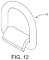
- FIG. 12 is a front perspective view of an embodiment of a connection point included in some embodiments of a present force damper
- FIG. 13 is a side cross sectional view of an embodiment of a present force damper
- FIG. 14 is a front elevational view of an embodiment of a present force damper
- FIG. 15 is a back elevational view of an embodiment of a present force damper
- FIG. 16 is a top perspective view of an embodiment of a present force damper
- FIG. 17 is a side cross sectional view of an embodiment of a present force damper
- FIGS. 18A and 18B are side cross-sectional views of embodiments of a present force damper before ( FIG. 18A ) and after ( FIG. 18B ) application of a force upon a driving member shaft;
- FIG. 19 is a side cross sectional view of an embodiment of a present force damper
- FIG. 20 is a side cross sectional view of an embodiment of a present force damper
- FIGS. 21A and 21B are side cross-sectional views of embodiments of a present force damper before ( FIG. 21A ) and after ( FIG. 21B ) application of a force upon a driving member shaft; and,
- FIGS. 22-24 are graphical representations of results of drop tests of present embodiments of force dampers described herein.
- a device comprising at least one of: a first element; a second element; and, a third element, is intended to be construed as any one of the following structural arrangements: a device comprising a first element; a device comprising a second element; a device comprising a third element; a device comprising a first element and a second element; a device comprising a first element and a third element; a device comprising a first element, a second element and a third element; or, a device comprising a second element and a third element.
- a device comprising a first element, a second element and/or a third element is intended to be construed as any one of the following structural arrangements: a device comprising a first element; a device comprising a second element; a device comprising a third element; a device comprising a first element and a second element; a device comprising a first element and a third element; a device comprising a first element, a second element and a third element; or, a device comprising a second element and a third element.
- the term “substantially” is synonymous with terms such as “nearly,” “very nearly,” “about,” “approximately,” “around,” “bordering on,” “close to,” “essentially,” “in the neighborhood of” “in the vicinity of” etc., and such terms may be used interchangeably as appearing in the specification and claims.
- proximate is synonymous with terms such as “nearby,” “close,” “adjacent,” “neighboring,” “immediate,” “adjoining,” etc., and such terms may be used interchangeably as appearing in the specification and claims.
- the term “approximately” is intended to mean values within ten percent of the specified value.
- non-rotatably connected elements we mean that: the elements are connected so that whenever one of the elements rotate, all the elements rotate; and relative rotation between the elements is not possible. Radial and/or axial movement of non-rotatably connected elements with respect to each other is possible, but not required. Additionally, “plastic deformation” is intended to mean instances when a sufficient load is applied to a material that causes a permanent change in shape to that material.
- the present invention broadly includes force damper 50 arranged to progressively arrest a first force imparted by an object moving in a first direction, i.e., the direction depicted by arrow 51 .
- Force damper 50 comprises housing 52 , driving member 54 and resilient member 56 .
- Housing 52 comprises first end 58 and second end 60 .
- First end 58 includes first surface 62 , second surface 64 opposite first surface 62 and first connection point 66 secured to first surface 62 .
- Second end 60 includes through bore 68 and third surface 70 opposingly disposed relative to second surface 64 .
- Driving member 54 comprises first end 72 , a second end 74 and shaft 76 therebetween.
- First end 72 comprises stop 78 and second end 74 comprises second connection point 80 .
- Resilient member 56 is formed from a material that at least partially undergoes plastic deformation when the first force is arrested. Resilient member 56 is disposed between stop 78 and third surface 70 , and imparts a second force on stop 78 toward second surface 64 and on second end 60 toward third surface 70 , as depicted by bi-directional arrow 82 .
- housing 52 encloses resilient member 56 .
- second end 60 of housing 52 comprises block 84 .
- Block 84 comprises through bore 68 and third surface 70 .
- block 84 is formed from a urethane material.
- block 84 may provide force damping in addition to that of resilient member 56 .
- block 84 may also be formed from a rigid material, e.g., a metal, and in those embodiments block 84 does not provide additional force damping.
- resilient member 56 is a resilient polymer, a leaf spring, a shock absorber, and/or a compression spring, e.g., compression spring 86 .
- resilient member 56 is compression spring 86
- compression spring 86 is formed from a chrome silicon steel material.
- the compression springs described herein are between 4-12′′.
- the compression springs described herein may be formed from elastomeric compounds such as elastomeric plastics, etc.
- force damper 50 further comprises securing line 88 selected from the group of: a rope, a cable, and/or a tether, and securing line 88 may in turn be connected to a harness and/or a belt. Subsequently, the object to be secured, e.g., a worker, a tool, a container, etc., is secured directly to the rope, cable and/or tether, or alternatively, secured directly to the harness and/or belt. It should be appreciated that securing line 88 is depicted as a rope only and that the structure and form of a cable and/or a tether are readily apparent to one having ordinary skill in the art and therefore depiction in the figures is unnecessary.
- securing lines are more suitable for the present force damper, e.g., stretchable and/or shock absorbing ropes, as additional force may be damped by these types of securing lines. However, including such types of securing lines is not required.
- the present invention broadly includes force damper 100 arranged to progressively arrest a first force imparted by an object moving in a first direction, i.e., the direction depicted by arrow 101 .
- Force damper 100 comprises housing 102 , driving member 104 and first and second resilient members 106 and 108 , respectively.
- Housing 102 comprises first end 110 and second end 112 .
- First end 110 includes first surface 114 , second surface 116 opposite first surface 114 and first connection point 118 secured to first surface 114 .
- Second end 112 includes through bore 120 and third surface 122 opposingly disposed relative to second surface 116 .
- Driving member 104 comprises first end 124 , second end 126 and shaft 128 therebetween.
- First end 124 comprises stop 130 and second end 126 comprises second connection point 132 .
- At least one of first and second resilient members 106 and 108 , respectively, is formed from a material that at least partially undergoes plastic deformation when the first force is arrested.
- first and second resilient members 106 and 108 undergoes plastic deformation while arresting the first force.
- one of the resilient members may be arranged to arrest a portion of the force and display visible, permanent deformation while the other resilient member provides force damping while undergoing only elastic deformation, i.e., temporary shape change with restoration to its original shape after damping is complete.
- First and second resilient members 106 and 108 are disposed between stop 130 and third surface 122 , and impart a second force on stop 130 toward second surface 116 and on second end 112 toward third surface 122 , as depicted by bi-directional arrow 134 .
- housing 102 further comprises reinforcement plate 136 arranged between first and second ends 110 and 112 , respectively, of housing 102 .
- housing 102 at least partially encloses first and second resilient members 106 and 108 , respectively. It should be appreciated that “partially encloses” is depicted in the figures in that tubes 138 include open portions 140 which permit the linear actuation of stop 130 as force damper 100 arrests the first force imparted by the object moving in the first direction.
- second end 112 of housing 102 comprises plate 142 .
- Plate 142 comprises through bore 120 .
- force damper 100 further comprises securing line 144 selected from the group of: a rope, a cable, and/or a tether, and securing line 144 may in turn be connected to a harness and/or a belt. Subsequently, the object to be secured, e.g., a worker, a tool, a container, etc., is secured directly to the rope, cable and/or tether, or alternatively, secured directly to the harness and/or belt. It should be appreciated that securing line 144 is depicted as a rope only and that the structure and form of a cable and/or a tether are readily apparent to one having ordinary skill in the art and therefore depiction in the figures is unnecessary.
- securing lines are more suitable for the present force damper, e.g., stretchable and/or shock absorbing ropes, as additional force may be damped by these types of securing lines. However, including such types of securing lines is not required.
- stop 130 extends perpendicularly from shaft 128 towards first and second resilient members 106 and 108 , respectively. As such, it should be appreciated that stop 130 is positioned between first and second resilient members 106 and 108 , respectively, and second surface 116 .
- first and second resilient members 106 and 108 are formed from a resilient polymer, a leaf spring, a shock absorber, and/or a compression spring, e.g., compression spring 146 .
- resilient members 106 and 108 are compression spring 146
- compression spring 146 is formed from a chrome silicon steel material.
- the compression springs described herein are between 4-12′′.
- the compression springs described herein may be formed from elastomeric compounds such as elastomeric plastics, etc.
- force damper 100 may include a variety of additional components and such components are not required in all embodiments. However, it should be appreciated that it is possible to include all or some of the components described below in a single embodiment if desired.
- force damper 100 may include plate 148 , reinforcement plate 136 , plate 142 , tubes 138 , stop 130 , tube 150 , shaft 128 , resilient members 106 and 108 , and connection points 118 and 132 .
- Tubes 138 partially enclose resilient members 106 and 108 .
- Tubes 138 are passed through openings 152 and 154 in plate 148 and subsequently through openings 156 and 158 in reinforcement plate 136 until ends 160 of tubes 138 abut plate 142 .
- Connection point 118 is fixedly secured to plate 148 .
- Stop 130 which is secured to end 124 of shaft 128 , is positioned within openings 140 of tubes 138 and between resilient members 106 and 108 and plate 148 .
- Reinforcement plate 136 may further include opening 162 wherein tube 150 is passed until it abuts plate 142 .
- Tube 150 provides an unrestricted passage for shaft 128 during its linear displacement.
- the combination of reinforcement plate 136 , tube 150 and plate 142 strengthens the overall structure of force damper 100 .
- Plate 142 may include through bore 120 adjacent to the abutment of tube 150 .
- the foregoing arrangement results in a force damper that solves problems presented by regulatory agencies and worker safety concerns, i.e., a force damper in a fall mitigation system should only be used one time.
- the foregoing embodiments provide force damping over a reduced range of travel, e.g., the present force damper travels approximately three to six inches while absorbing the force of a falling object.
- existing force damping systems required far greater distance to damp the force of a falling object, e.g., two and a half to three feet. It should be appreciated that the present force damper system may be configured to travel lesser or greater lengths depending on the needs of the system.
- All the various resilient members described above may provide some elastic deformation, the resilient members are selected for particular falling masses that will always impart plastic deformation on at least one of the resilient members while they arrest a first force imparted by an object moving in a first direction.
- one set of resilient members may be rated for arresting the force created by a falling object ranging from 100 kilograms (kg) to 150 kg, while a different set of resilient members may be rated for falling objects ranging from 150 kg to 200 kg. It is critical that at least one of the resilient members experiences plastic deformation so that single use of each the devices can be ensured.
- the plastic deformation of at least one of the resilient members with no return to its original shape/size provides a readily observable characteristic of the present force damper that ensures a user of the device can determine if it has been previously used for its intended purpose, i.e., arresting the force created by an object moving in a first direction.
- a force damper can include, for example, one or more resilient members used in association with a so-called Belleville washer having a frustoconical shape, driving member shafts including zig-zag-like, sinusoidal-like, or helical-like portions that may be elongated and plastically deformed upon application of a force to thereby attenuate the force applied thereto, or so-called compressible/collapsible/compactible crumple zones configured to be compressed/collapsed/compacted to thereby absorb/attenuate a force applied to the driving member shaft.
- FIGS. 17-24 primarily illustrate embodiments of a force damper comprising a single housing and single driving member, etc., such embodiments comprise can more than a single housing and driving member shaft, and, for example, may comprise so-called dual-housing type embodiments.
- force damper 200 A is arranged to progressively arrest a first force imparted by an object moving in a first direction, i.e., the direction depicted by arrow 202 .
- Force damper 200 A comprises housing 204 , driving member 206 and resilient member 208 .
- Housing 204 comprises first end 216 and second end 218 and may be fabricated from materials such as steel, aluminum, other lightweight metals, fiberglass, carbon fiber, composites, or combinations thereof.
- First end 216 includes first surface 220 , second surface 222 opposite first surface 220 and first connection point 224 connected to housing 204 , for purposes of, for example, securing the force damper to a fixed structure or a fall arrest apparatus.
- Second end 218 includes through bore 226 and third surface 230 opposingly disposed relative to second surface 222 .
- Driving member 206 comprises first end 232 , a second end 234 and driving member shaft 236 therebetween.
- First end 232 comprises driving member stop 238 and second end 234 comprises second connection point 240 for purposes of, for example, securing an object or person thereto by means of a rope, cable, webbing, lanyard, tear-away lanyard, etc. (not shown).
- Resilient member 208 is formed from a material that at least partially undergoes plastic deformation when the first force is arrested.
- Resilient member 208 is disposed between driving member stop 238 and third surface 230 of housing end wall 228 and imparts a second force on driving member stop 238 toward second surface 222 and on second end 218 toward third surface 230 , as depicted by bi-directional arrow 242 .
- housing 204 encloses resilient member 208 .
- one or more of first end 216 and second end 218 of housing 204 can comprise one or more semi-resilient members 212 .
- Semi-resilient members 212 comprise a through bore allowing driving member shaft 236 to pass therethrough.
- semi-resilient members 212 are formed from a urethane material which serves to further attenuate a force applied to the driving member 206 .
- semi-resilient member 212 is composed of 60 durometer urethane, or like compound, having a thickness between 3 ⁇ 8 and 1 ⁇ 2′′.
- semi-resilient members 212 may provide force damping in addition to that of resilient member 208 .
- semi-resilient member 212 e.g. a urethane washer
- a force damper may further include a so-called Belleville washer 214 , which is disposed within housing 204 between driving member stop 238 and end wall 228 of housing 204 .
- Belleville washer 214 has a frustoconical shape and includes a through bore allowing the driving member shaft 236 to pass therethrough.
- Belleville washer 214 can be formed from a plastically deformable material with no return to its original shape/size, such as a metal, plastics, polymers, from sacrificial/fracturable/frangible materials, or combinations thereof so as to provide a readily observable characteristic as to whether the force damper has been subject to prior use.
- housing 204 may include a viewing window or slit proximate the location of Belleville washer 214 so to allow ready inspection thereof.
- FIG. 17 illustrates Belleville washer 214 as being disposed between semi-resilient member 212 and end wall 228 of second end 218 of housing 204 , it may be positioned otherwise within housing 204 and at any position between end wall 228 and driving member stop 238 .
- Belleville washer 214 can be formed of an elastically deformable material that returns to its original shape. Additionally, while FIG. 17 illustrates Belleville washer 214 being positioned such that its concave side is disposed toward end wall 218 , it may be positioned such that its concave side is oppositely positioned toward driving member stop 238 . Also, while only a single Belleville washer 214 is shown in FIG. 17 , more than one Belleville washer 214 may be utilized depending upon the specific application, i.e., the object and/or the amount of force to be attenuated/arrested.
- Belleville washer 214 may be positioned to contact one another in a stacked, or nested-type arrangement, positioned such that they contact one another but do not nest with one another, positioned in such a way that that they do not contact one another, e.g. on opposite ends of housing 204 , or combinations thereof depending upon the specific application.
- resilient member 208 is a resilient polymer, a leaf spring, a shock absorber, and/or a compression spring, e.g., compression spring 210 .
- resilient member 208 is compression spring 210
- compression spring 210 is formed from a chrome silicon steel material.
- the compression springs described herein are between 4-12′′.
- the compression springs described herein may be formed from elastomeric compounds such as elastomeric plastics, etc.
- force damper 220 A further comprises a securing line (not shown) selected from the group of: rope, cable, webbing, tether, lanyard, tear-away lanyard, combinations thereof, etc., and the securing line may in turn be connected to a harness and/or a belt. Subsequently, the object to be secured, e.g., a worker, a tool, a container, etc., is secured directly to the securing line rope, cable and/or tether, or alternatively, secured directly to the harness and/or belt.
- a securing line selected from the group of: rope, cable, webbing, tether, lanyard, tear-away lanyard, combinations thereof, etc.
- securing lines may be more suitable for the present force damper, e.g., stretchable and/or shock absorbing ropes, tear away lanyards, as additional force may be damped by these types of securing lines. However, including such types of securing lines is not required.
- force dampers 200 B- 200 D are substantially similar to force damper 220 A, but are primarily different in that they can include differently configured driving member shafts 236 , which are configured to be elongated upon application of a sufficient force in the first direction 202 . That is, as force dampers 200 A- 200 D include similar structural elements, discussion of such similar structural elements is not re-presented herein, and the following description is substantially limited to a discussion of the differences between embodiments 200 A- 200 D.
- force dampers 200 B- 200 D are generally configured to comprise plastically deformable and elongatable driving member shafts 236 including zig-zag/sinusoidal/helical-like portions 237 positioned between driving member first end 232 and driving member second end 234 .
- the driving member shaft 236 can be formed from a plastically deformable material that does not allow return to its original shape/size, such as a metal or certain polymers, from other sacrificial/non-reusable materials, or combinations thereof so as to provide a readily observable characteristic as to whether the force damper has been subject to prior use.
- housing 204 may include a viewing window or slit proximate location of zig-zag/sinusoidal/helical-like portions 237 so to allow ready inspection thereof (not shown) such that operational state may be readily determined.
- driving member shafts 236 may be elastically deformable such that they substantially return to their original shapes.
- the driving member shafts 236 including zig-zag/sinusoidal/helical-like portions 237 can be formed from a generally flat stock and include zig-zag-like folded/pleated portions 237 in the case of FIGS. 18A and 18B , square sinusoidal-type portions 237 in the case of FIG. 19 , and helical-type portions 237 in the case of FIG. 20 .
- FIGS. 18A-20 in the case of plastically deformable driving member shafts, the driving member shafts 236 including zig-zag/sinusoidal/helical-like portions 237 can be formed from a generally flat stock and include zig-zag-like folded/pleated portions 237 in the case of FIGS. 18A and 18B , square sinusoidal-type portions 237 in the case of FIG. 19 , and helical-type portions 237 in the case of FIG. 20 .
- FIGS. 18A-20 in the case of plastically deformable driving member shafts, the driving member shafts 236 including zig
- zig-zag-like folded/pleated portions 237 are maintained in a so-called start position.
- FIG. 18B upon application of a sufficient force, zig-zag-like folded/pleated portions 237 become elongated and are plastically deformed at the ending position shown by way of example in FIG. 18B .
- driving member shafts 236 including zig-zag-like folded/pleated portions 237 can also be configured to include, for example, markings, colored markings, knurling, etching, etc. along a length thereof, for example, proximate through bore 226 of housing, to show whether the force damper has been previously utilized and the driving member shafts 236 elongated and subject to plastic deformation.
- driving member shafts 236 including zig-zag/sinusoidal/helical-like portions 237 can be formed of stock of varying thickness and/or varying number of folds/pleats/turns based on the particular application and/or object that is secured thereto. In some embodiments, the driving member shafts 236 are formed from 1 ⁇ 8′′ steel. Furthermore, as shown in FIGS.
- force dampers including driving member shafts 236 including zig-zag/sinusoidal/helical-like portions 237 can also optionally include semi-resilient members 212 and/or Belleville washers 214 (as shown by the dashed lines in such figures).
- force damper 200 E may be configured to comprise a so-called collapsible/compressible/compactable crush zone configured to reduce or attenuate the amount of force applied in first direction 202 .
- force damper 200 E can be configured to include driving member 206 having a driving member stop 238 having a tapered shape for purposes of contacting a collapsible/compressible/compactable tapered wall 244 of housing 204 .
- collapsible/compressible/compactable tapered wall 244 can include, for example, channels or interstitial portions 248 disposed between structural portions 244 thereof such that upon action by the tapered driving member stop 238 , such walls may collapse/compress/compact upon themselves and/or may be partially directionally disposed toward second end 218 as shown in FIG. 21B .
- collapsible/compressible/compactable crush zones may be configured to comprise a structural member of the housing, e.g., a wall of the housing itself, or may be configured to comprise a member or zone secured, disposed on, or adhered to an inner wall of housing 204 .
- collapsible/compressible/compactable zone 244 may be formed of metals, polymers, foams, resilient materials, fracturable or frangible materials, or combinations thereof. Additionally, while FIGS. 21A and 21B illustrate a force damper as comprising a so-called collapsible/compressible/compactable crush zone only, such zones may be used in association with one or more of the force damper embodiments or aspects thereof previously discussed herein.
- Walls of the housing and/or tapered wall 244 may also be configured in a stepped fashion, for example, to ensure that a collapsible/compressible/compactable member or zone secured, disposed on, or adhered to an inner wall of housing 204 is not dislodged as a result of the application of a force in the first direction.
- FIGS. 22-24 are graphical illustrations of drop tests performed according ANSI Z359 requirements in order to assess the dampening or attenuation of force provided by force dampers in accordance with the instant disclosure.
- a 282 pound weight was utilized, the weight dropped from a same height free and clear of obstructions, and each force damper included a driving member shaft including a zig-zag-like folded portion as shown, for example, in FIGS. 18A and 18B .
- a Belleville washer and/or one or more urethane semi-resilient members were utilized. As shown in FIG.
- MAF Maximum Arresting Force
- AAF Average Arresting Force
- MAF Maximum Arresting Force
- AAF Average Arresting Force
Landscapes
- Engineering & Computer Science (AREA)
- General Engineering & Computer Science (AREA)
- Health & Medical Sciences (AREA)
- General Health & Medical Sciences (AREA)
- Business, Economics & Management (AREA)
- Emergency Management (AREA)
- Mechanical Engineering (AREA)
- Vibration Dampers (AREA)
Abstract
Description
- 50 Force Damper
- 51 1st Direction/Force
- 52 Housing
- 54 Driving Member
- 56 Resilient Member
- 58 1st End
- 60 2nd End
- 62 1st Surface
- 64 2nd Surface
- 66 1st Connection Point
- 68 Through bore
- 70 3rd Surface
- 72 Driving Member 1st End
- 74
Driving Member 2nd End - 76 Driving Member Shaft
- 78 Driving Member Stop
- 80 2nd Connection Point
- 82 2nd Direction/Force
- 84 Block
- 86 Compression Spring
- 88 Securing Line
- 100 Force Damper
- 101 Direction/Force
- 102 Housing
- 104 Driving Member
- 106 1st Resilient Member
- 108 2nd Resilient Member
- 110
Housing 1st End - 112
Housing 2nd End - 114 1st Surface
- 116 2nd Surface
- 118 1st Connection Point
- 120 Through bore
- 122 3rd Surface
-
124 Driving Member 1st End - 126
Driving Member 2nd End - 128 Driving Member Shaft
- 130 Driving Member Stop
- 132 2nd Connection Point
- 134 2nd Direction/Force
- 136 Reinforcement Plate
- 138 Tube(s)
- 140 Tube Open Portion
- 142 2nd End Plate
- 144 Securing Line
- 146 Compression Spring
- 148 1st End Plate
- 150 Tube
- 152 Opening
- 154 Opening
- 156 Opening
- 158 Opening
-
160 Tube 138 End - 162 Opening
- 200A-200E Force Damper
- 202 1st Direction/Force
- 204 Housing
- 206 Driving Member
- 208 Resilient Member
- 210 Compression Spring
- 212 Semi-Resilient Member (Washer)
- 214 Belleville Washer
- 216 1st End
- 218 2nd End
- 220 1st Surface
- 222 2nd Surface
- 224 1st Connection Point
- 226 Through Bore
- 228 End Wall
- 230 3rd Surface
- 232
Driving Member 1st End - 234
Driving Member 2nd End - 236 Driving Member Shaft
- 237 Zig-zag/Sinusoidal/Helical-like Portion
- 238 Driving Member stop
- 240 2nd Connection Point
- 242 2nd Direction/Force
- 244 Collapsible/Compressible/Compactable Portion
- 246 Structural Portion
- 248 Interstitial Portion
Claims (7)
Priority Applications (4)
| Application Number | Priority Date | Filing Date | Title |
|---|---|---|---|
| US16/784,939 US11090518B2 (en) | 2017-12-27 | 2020-02-07 | Force damper |
| US17/185,071 US20210178202A1 (en) | 2017-12-27 | 2021-02-25 | Force damping system including a force damper, a tear-away lanyard, and a force absorbing harness |
| US17/305,690 US20210339064A1 (en) | 2017-12-27 | 2021-07-13 | Force damper |
| US18/547,797 US20240299784A1 (en) | 2017-12-27 | 2022-02-24 | Force damping system including force damper, reinforced non-flammable bailout lanyard, and force absorbing fireman harness |
Applications Claiming Priority (3)
| Application Number | Priority Date | Filing Date | Title |
|---|---|---|---|
| US201762610786P | 2017-12-27 | 2017-12-27 | |
| US16/113,618 US20190195310A1 (en) | 2017-12-27 | 2018-08-27 | Force damper |
| US16/784,939 US11090518B2 (en) | 2017-12-27 | 2020-02-07 | Force damper |
Related Parent Applications (1)
| Application Number | Title | Priority Date | Filing Date |
|---|---|---|---|
| US16/113,618 Continuation-In-Part US20190195310A1 (en) | 2017-12-27 | 2018-08-27 | Force damper |
Related Child Applications (2)
| Application Number | Title | Priority Date | Filing Date |
|---|---|---|---|
| US17/185,071 Continuation-In-Part US20210178202A1 (en) | 2017-12-27 | 2021-02-25 | Force damping system including a force damper, a tear-away lanyard, and a force absorbing harness |
| US17/305,690 Division US20210339064A1 (en) | 2017-12-27 | 2021-07-13 | Force damper |
Publications (2)
| Publication Number | Publication Date |
|---|---|
| US20200171333A1 US20200171333A1 (en) | 2020-06-04 |
| US11090518B2 true US11090518B2 (en) | 2021-08-17 |
Family
ID=70848943
Family Applications (2)
| Application Number | Title | Priority Date | Filing Date |
|---|---|---|---|
| US16/784,939 Active US11090518B2 (en) | 2017-12-27 | 2020-02-07 | Force damper |
| US17/305,690 Pending US20210339064A1 (en) | 2017-12-27 | 2021-07-13 | Force damper |
Family Applications After (1)
| Application Number | Title | Priority Date | Filing Date |
|---|---|---|---|
| US17/305,690 Pending US20210339064A1 (en) | 2017-12-27 | 2021-07-13 | Force damper |
Country Status (1)
| Country | Link |
|---|---|
| US (2) | US11090518B2 (en) |
Cited By (1)
| Publication number | Priority date | Publication date | Assignee | Title |
|---|---|---|---|---|
| US11448280B2 (en) * | 2016-01-05 | 2022-09-20 | The Hong Kong University Of Science And Technology | Bi-linear energy dissipating and shock absorbing device for cable subjected to tension |
Families Citing this family (4)
| Publication number | Priority date | Publication date | Assignee | Title |
|---|---|---|---|---|
| DE102018005492A1 (en) * | 2018-07-11 | 2020-01-16 | Sumitomo Riko Company Limited | Vibration absorber and method for producing a vibration absorber |
| US10987983B1 (en) * | 2020-10-29 | 2021-04-27 | King Abdulaziz University | Dampening safety device able to attach to a soft towline and methods for use |
| US20250065158A1 (en) * | 2022-07-05 | 2025-02-27 | Deuer Development | Safe access system |
| IT202200022779A1 (en) * | 2022-11-04 | 2024-05-04 | Sidermarine S R L | Fall arrest safety device |
Citations (22)
| Publication number | Priority date | Publication date | Assignee | Title |
|---|---|---|---|---|
| US2421822A (en) * | 1944-04-15 | 1947-06-10 | Gen Spring Corp | Spring device |
| US2678796A (en) * | 1952-04-30 | 1954-05-18 | Waugh Equipment Co | Vibration and shock isolator |
| US3462137A (en) * | 1967-09-15 | 1969-08-19 | Mac Lean Fogg Lock Nut Co | Automatic load binder |
| US3610606A (en) * | 1969-10-08 | 1971-10-05 | Gary E Andrews | Turnbuckle and shock absorber |
| US3637174A (en) * | 1969-09-02 | 1972-01-25 | Stone & Webster Eng Corp | Spring hanger |
| US5240232A (en) * | 1991-12-16 | 1993-08-31 | Abb Impell Corporation | Pipe restraint |
| US5332071A (en) * | 1993-03-09 | 1994-07-26 | Sinco Incorporated | Shock absorber for safety cable system |
| US5358068A (en) * | 1992-10-30 | 1994-10-25 | Whitmer Gerald T | Safety system including cable tensioner and shock absorber |
| US5458214A (en) * | 1992-10-14 | 1995-10-17 | Rose Systems, Inc. | Safety apparatus |
| US6471198B2 (en) * | 2000-06-02 | 2002-10-29 | Lord Corporation | Vibration isolator |
| US20020177906A1 (en) * | 1998-04-10 | 2002-11-28 | Phillips Van L. | Active shock module prosthesis |
| US20040145098A1 (en) * | 2003-01-28 | 2004-07-29 | Ken Thaler | Energy absorber for fall arrest systems |
| DE202008002704U1 (en) | 2008-02-26 | 2008-05-15 | Skylotec Gmbh | absorber |
| US8608142B2 (en) * | 2009-05-05 | 2013-12-17 | Geobrugg Ag | Device for absorbing kinetic energy of a moving body |
| US20160363186A1 (en) * | 2015-05-14 | 2016-12-15 | Barnes Group Inc. | Interference Arrangement for Spring |
| US20170128756A1 (en) * | 2015-11-07 | 2017-05-11 | Alexander Andrew, Inc. Dba Falltech | Energy absorber |
| US20180264297A1 (en) * | 2015-05-05 | 2018-09-20 | Safetylink Pty Ltd | An anchor |
| US20180323489A1 (en) * | 2016-04-05 | 2018-11-08 | Howard R. Vermillion, Jr. | Truss Reinforced Radome Crown Structure Shock Absorbing And Recoiling Sysytem |
| US20190176733A1 (en) * | 2017-12-13 | 2019-06-13 | Ford Global Technologies, Llc | Plastically deformable shock absorber |
| US20190195310A1 (en) | 2017-12-27 | 2019-06-27 | On Top Safety, Inc. | Force damper |
| US20190234480A1 (en) * | 2018-01-31 | 2019-08-01 | Suhder Ind Co., Ltd. | Magnetic suspension shock absorber |
| US10663110B1 (en) * | 2018-12-17 | 2020-05-26 | Divergent Technologies, Inc. | Metrology apparatus to facilitate capture of metrology data |
-
2020
- 2020-02-07 US US16/784,939 patent/US11090518B2/en active Active
-
2021
- 2021-07-13 US US17/305,690 patent/US20210339064A1/en active Pending
Patent Citations (22)
| Publication number | Priority date | Publication date | Assignee | Title |
|---|---|---|---|---|
| US2421822A (en) * | 1944-04-15 | 1947-06-10 | Gen Spring Corp | Spring device |
| US2678796A (en) * | 1952-04-30 | 1954-05-18 | Waugh Equipment Co | Vibration and shock isolator |
| US3462137A (en) * | 1967-09-15 | 1969-08-19 | Mac Lean Fogg Lock Nut Co | Automatic load binder |
| US3637174A (en) * | 1969-09-02 | 1972-01-25 | Stone & Webster Eng Corp | Spring hanger |
| US3610606A (en) * | 1969-10-08 | 1971-10-05 | Gary E Andrews | Turnbuckle and shock absorber |
| US5240232A (en) * | 1991-12-16 | 1993-08-31 | Abb Impell Corporation | Pipe restraint |
| US5458214A (en) * | 1992-10-14 | 1995-10-17 | Rose Systems, Inc. | Safety apparatus |
| US5358068A (en) * | 1992-10-30 | 1994-10-25 | Whitmer Gerald T | Safety system including cable tensioner and shock absorber |
| US5332071A (en) * | 1993-03-09 | 1994-07-26 | Sinco Incorporated | Shock absorber for safety cable system |
| US20020177906A1 (en) * | 1998-04-10 | 2002-11-28 | Phillips Van L. | Active shock module prosthesis |
| US6471198B2 (en) * | 2000-06-02 | 2002-10-29 | Lord Corporation | Vibration isolator |
| US20040145098A1 (en) * | 2003-01-28 | 2004-07-29 | Ken Thaler | Energy absorber for fall arrest systems |
| DE202008002704U1 (en) | 2008-02-26 | 2008-05-15 | Skylotec Gmbh | absorber |
| US8608142B2 (en) * | 2009-05-05 | 2013-12-17 | Geobrugg Ag | Device for absorbing kinetic energy of a moving body |
| US20180264297A1 (en) * | 2015-05-05 | 2018-09-20 | Safetylink Pty Ltd | An anchor |
| US20160363186A1 (en) * | 2015-05-14 | 2016-12-15 | Barnes Group Inc. | Interference Arrangement for Spring |
| US20170128756A1 (en) * | 2015-11-07 | 2017-05-11 | Alexander Andrew, Inc. Dba Falltech | Energy absorber |
| US20180323489A1 (en) * | 2016-04-05 | 2018-11-08 | Howard R. Vermillion, Jr. | Truss Reinforced Radome Crown Structure Shock Absorbing And Recoiling Sysytem |
| US20190176733A1 (en) * | 2017-12-13 | 2019-06-13 | Ford Global Technologies, Llc | Plastically deformable shock absorber |
| US20190195310A1 (en) | 2017-12-27 | 2019-06-27 | On Top Safety, Inc. | Force damper |
| US20190234480A1 (en) * | 2018-01-31 | 2019-08-01 | Suhder Ind Co., Ltd. | Magnetic suspension shock absorber |
| US10663110B1 (en) * | 2018-12-17 | 2020-05-26 | Divergent Technologies, Inc. | Metrology apparatus to facilitate capture of metrology data |
Non-Patent Citations (1)
| Title |
|---|
| Model No. 1340101 PROTM Stretch Shock Absorbing Lanyard manufactured by Protecta®, 3M Protecta Catalog Rev E, Fall 2016. |
Cited By (1)
| Publication number | Priority date | Publication date | Assignee | Title |
|---|---|---|---|---|
| US11448280B2 (en) * | 2016-01-05 | 2022-09-20 | The Hong Kong University Of Science And Technology | Bi-linear energy dissipating and shock absorbing device for cable subjected to tension |
Also Published As
| Publication number | Publication date |
|---|---|
| US20200171333A1 (en) | 2020-06-04 |
| US20210339064A1 (en) | 2021-11-04 |
Similar Documents
| Publication | Publication Date | Title |
|---|---|---|
| US11090518B2 (en) | Force damper | |
| US20190195310A1 (en) | Force damper | |
| US5332071A (en) | Shock absorber for safety cable system | |
| US11633634B2 (en) | Cut-resistant leading edge fall arrest system and method | |
| US20210178202A1 (en) | Force damping system including a force damper, a tear-away lanyard, and a force absorbing harness | |
| US3308908A (en) | Energy absorber | |
| RU2517263C1 (en) | Blast-proof panel | |
| RU2540179C2 (en) | Safety device for explosive facilities | |
| EP3423162A1 (en) | Line retraction device having a damper assembly | |
| JP2020527205A (en) | Energy absorber | |
| DE102015205144A1 (en) | Centrifugal pendulum with spring element as a stop damper | |
| US10267374B2 (en) | Impact attenuation device | |
| EP3862053B1 (en) | Improved force damper | |
| US20240299784A1 (en) | Force damping system including force damper, reinforced non-flammable bailout lanyard, and force absorbing fireman harness | |
| KR19990008351A (en) | Earthquake Pipe Restraint and How to Use | |
| US20090212474A1 (en) | Energy Absorption Apparatus for Fall Protection Systems | |
| RU2582130C1 (en) | Kochetov method for protection of explosive objects | |
| US5697478A (en) | Sacrifical tube shock attenuation | |
| US20160102725A1 (en) | Energy absorber | |
| RU2625079C1 (en) | Emergency situation simulator | |
| RU2520584C1 (en) | Device for protection of internal space of premises against fragments of wall damaged in result of impact from outside | |
| Hernández et al. | Energy dissipating component in fall arrest system | |
| RU2658931C2 (en) | Explosion proof panel with emergency warning system | |
| RU2600243C1 (en) | Kochetov explosion proof panel with emergency warning system | |
| GB2305230A (en) | Safety lifeline shock absorber |
Legal Events
| Date | Code | Title | Description |
|---|---|---|---|
| FEPP | Fee payment procedure |
Free format text: ENTITY STATUS SET TO UNDISCOUNTED (ORIGINAL EVENT CODE: BIG.); ENTITY STATUS OF PATENT OWNER: SMALL ENTITY |
|
| FEPP | Fee payment procedure |
Free format text: ENTITY STATUS SET TO SMALL (ORIGINAL EVENT CODE: SMAL); ENTITY STATUS OF PATENT OWNER: SMALL ENTITY |
|
| STPP | Information on status: patent application and granting procedure in general |
Free format text: RESPONSE TO NON-FINAL OFFICE ACTION ENTERED AND FORWARDED TO EXAMINER |
|
| STPP | Information on status: patent application and granting procedure in general |
Free format text: FINAL REJECTION MAILED |
|
| STPP | Information on status: patent application and granting procedure in general |
Free format text: RESPONSE AFTER FINAL ACTION FORWARDED TO EXAMINER |
|
| STPP | Information on status: patent application and granting procedure in general |
Free format text: NOTICE OF ALLOWANCE MAILED -- APPLICATION RECEIVED IN OFFICE OF PUBLICATIONS |
|
| STPP | Information on status: patent application and granting procedure in general |
Free format text: PUBLICATIONS -- ISSUE FEE PAYMENT RECEIVED |
|
| STPP | Information on status: patent application and granting procedure in general |
Free format text: PUBLICATIONS -- ISSUE FEE PAYMENT VERIFIED |
|
| STCF | Information on status: patent grant |
Free format text: PATENTED CASE |
|
| AS | Assignment |
Owner name: ON TOP SAFETY EQUIPMENT, LLC, NEW YORK Free format text: ASSIGNMENT OF ASSIGNORS INTEREST;ASSIGNOR:ON TOP SAFETY, INC.;REEL/FRAME:066108/0069 Effective date: 20240111 Owner name: ON TOP SAFETY EQUIPMENT, LLC, NEW YORK Free format text: ASSIGNMENT OF ASSIGNOR'S INTEREST;ASSIGNOR:ON TOP SAFETY, INC.;REEL/FRAME:066108/0069 Effective date: 20240111 |
|
| MAFP | Maintenance fee payment |
Free format text: PAYMENT OF MAINTENANCE FEE, 4TH YR, SMALL ENTITY (ORIGINAL EVENT CODE: M2551); ENTITY STATUS OF PATENT OWNER: SMALL ENTITY Year of fee payment: 4 |