US10470886B2 - Method of a rig - Google Patents
Method of a rig Download PDFInfo
- Publication number
- US10470886B2 US10470886B2 US15/324,437 US201515324437A US10470886B2 US 10470886 B2 US10470886 B2 US 10470886B2 US 201515324437 A US201515324437 A US 201515324437A US 10470886 B2 US10470886 B2 US 10470886B2
- Authority
- US
- United States
- Prior art keywords
- rig
- bone
- virtual
- circular
- cartilage
- Prior art date
- Legal status (The legal status is an assumption and is not a legal conclusion. Google has not performed a legal analysis and makes no representation as to the accuracy of the status listed.)
- Active, expires
Links
Images


Classifications
-
- A—HUMAN NECESSITIES
- A61—MEDICAL OR VETERINARY SCIENCE; HYGIENE
- A61F—FILTERS IMPLANTABLE INTO BLOOD VESSELS; PROSTHESES; DEVICES PROVIDING PATENCY TO, OR PREVENTING COLLAPSING OF, TUBULAR STRUCTURES OF THE BODY, e.g. STENTS; ORTHOPAEDIC, NURSING OR CONTRACEPTIVE DEVICES; FOMENTATION; TREATMENT OR PROTECTION OF EYES OR EARS; BANDAGES, DRESSINGS OR ABSORBENT PADS; FIRST-AID KITS
- A61F2/00—Filters implantable into blood vessels; Prostheses, i.e. artificial substitutes or replacements for parts of the body; Appliances for connecting them with the body; Devices providing patency to, or preventing collapsing of, tubular structures of the body, e.g. stents
- A61F2/02—Prostheses implantable into the body
- A61F2/30—Joints
-
- A—HUMAN NECESSITIES
- A61—MEDICAL OR VETERINARY SCIENCE; HYGIENE
- A61B—DIAGNOSIS; SURGERY; IDENTIFICATION
- A61B17/00—Surgical instruments, devices or methods
- A61B17/14—Surgical saws
- A61B17/15—Guides therefor
-
- A—HUMAN NECESSITIES
- A61—MEDICAL OR VETERINARY SCIENCE; HYGIENE
- A61B—DIAGNOSIS; SURGERY; IDENTIFICATION
- A61B17/00—Surgical instruments, devices or methods
- A61B17/14—Surgical saws
- A61B17/15—Guides therefor
- A61B17/154—Guides therefor for preparing bone for knee prosthesis
-
- A—HUMAN NECESSITIES
- A61—MEDICAL OR VETERINARY SCIENCE; HYGIENE
- A61B—DIAGNOSIS; SURGERY; IDENTIFICATION
- A61B17/00—Surgical instruments, devices or methods
- A61B17/16—Instruments for performing osteoclasis; Drills or chisels for bones; Trepans
- A61B17/17—Guides or aligning means for drills, mills, pins or wires
- A61B17/1739—Guides or aligning means for drills, mills, pins or wires specially adapted for particular parts of the body
- A61B17/1764—Guides or aligning means for drills, mills, pins or wires specially adapted for particular parts of the body for the knee
- A61B17/1767—Guides or aligning means for drills, mills, pins or wires specially adapted for particular parts of the body for the knee for the patella
-
- A—HUMAN NECESSITIES
- A61—MEDICAL OR VETERINARY SCIENCE; HYGIENE
- A61B—DIAGNOSIS; SURGERY; IDENTIFICATION
- A61B34/00—Computer-aided surgery; Manipulators or robots specially adapted for use in surgery
- A61B34/10—Computer-aided planning, simulation or modelling of surgical operations
-
- A—HUMAN NECESSITIES
- A61—MEDICAL OR VETERINARY SCIENCE; HYGIENE
- A61F—FILTERS IMPLANTABLE INTO BLOOD VESSELS; PROSTHESES; DEVICES PROVIDING PATENCY TO, OR PREVENTING COLLAPSING OF, TUBULAR STRUCTURES OF THE BODY, e.g. STENTS; ORTHOPAEDIC, NURSING OR CONTRACEPTIVE DEVICES; FOMENTATION; TREATMENT OR PROTECTION OF EYES OR EARS; BANDAGES, DRESSINGS OR ABSORBENT PADS; FIRST-AID KITS
- A61F2/00—Filters implantable into blood vessels; Prostheses, i.e. artificial substitutes or replacements for parts of the body; Appliances for connecting them with the body; Devices providing patency to, or preventing collapsing of, tubular structures of the body, e.g. stents
- A61F2/02—Prostheses implantable into the body
- A61F2/30—Joints
- A61F2/30756—Cartilage endoprostheses
-
- A—HUMAN NECESSITIES
- A61—MEDICAL OR VETERINARY SCIENCE; HYGIENE
- A61F—FILTERS IMPLANTABLE INTO BLOOD VESSELS; PROSTHESES; DEVICES PROVIDING PATENCY TO, OR PREVENTING COLLAPSING OF, TUBULAR STRUCTURES OF THE BODY, e.g. STENTS; ORTHOPAEDIC, NURSING OR CONTRACEPTIVE DEVICES; FOMENTATION; TREATMENT OR PROTECTION OF EYES OR EARS; BANDAGES, DRESSINGS OR ABSORBENT PADS; FIRST-AID KITS
- A61F2/00—Filters implantable into blood vessels; Prostheses, i.e. artificial substitutes or replacements for parts of the body; Appliances for connecting them with the body; Devices providing patency to, or preventing collapsing of, tubular structures of the body, e.g. stents
- A61F2/02—Prostheses implantable into the body
- A61F2/30—Joints
- A61F2/32—Joints for the hip
- A61F2/36—Femoral heads ; Femoral endoprostheses
-
- A—HUMAN NECESSITIES
- A61—MEDICAL OR VETERINARY SCIENCE; HYGIENE
- A61F—FILTERS IMPLANTABLE INTO BLOOD VESSELS; PROSTHESES; DEVICES PROVIDING PATENCY TO, OR PREVENTING COLLAPSING OF, TUBULAR STRUCTURES OF THE BODY, e.g. STENTS; ORTHOPAEDIC, NURSING OR CONTRACEPTIVE DEVICES; FOMENTATION; TREATMENT OR PROTECTION OF EYES OR EARS; BANDAGES, DRESSINGS OR ABSORBENT PADS; FIRST-AID KITS
- A61F2/00—Filters implantable into blood vessels; Prostheses, i.e. artificial substitutes or replacements for parts of the body; Appliances for connecting them with the body; Devices providing patency to, or preventing collapsing of, tubular structures of the body, e.g. stents
- A61F2/02—Prostheses implantable into the body
- A61F2/30—Joints
- A61F2/38—Joints for elbows or knees
-
- A—HUMAN NECESSITIES
- A61—MEDICAL OR VETERINARY SCIENCE; HYGIENE
- A61F—FILTERS IMPLANTABLE INTO BLOOD VESSELS; PROSTHESES; DEVICES PROVIDING PATENCY TO, OR PREVENTING COLLAPSING OF, TUBULAR STRUCTURES OF THE BODY, e.g. STENTS; ORTHOPAEDIC, NURSING OR CONTRACEPTIVE DEVICES; FOMENTATION; TREATMENT OR PROTECTION OF EYES OR EARS; BANDAGES, DRESSINGS OR ABSORBENT PADS; FIRST-AID KITS
- A61F2/00—Filters implantable into blood vessels; Prostheses, i.e. artificial substitutes or replacements for parts of the body; Appliances for connecting them with the body; Devices providing patency to, or preventing collapsing of, tubular structures of the body, e.g. stents
- A61F2/02—Prostheses implantable into the body
- A61F2/30—Joints
- A61F2/46—Special tools for implanting artificial joints
- A61F2/4657—Measuring instruments used for implanting artificial joints
-
- A—HUMAN NECESSITIES
- A61—MEDICAL OR VETERINARY SCIENCE; HYGIENE
- A61B—DIAGNOSIS; SURGERY; IDENTIFICATION
- A61B34/00—Computer-aided surgery; Manipulators or robots specially adapted for use in surgery
- A61B34/10—Computer-aided planning, simulation or modelling of surgical operations
- A61B2034/108—Computer aided selection or customisation of medical implants or cutting guides
-
- A—HUMAN NECESSITIES
- A61—MEDICAL OR VETERINARY SCIENCE; HYGIENE
- A61F—FILTERS IMPLANTABLE INTO BLOOD VESSELS; PROSTHESES; DEVICES PROVIDING PATENCY TO, OR PREVENTING COLLAPSING OF, TUBULAR STRUCTURES OF THE BODY, e.g. STENTS; ORTHOPAEDIC, NURSING OR CONTRACEPTIVE DEVICES; FOMENTATION; TREATMENT OR PROTECTION OF EYES OR EARS; BANDAGES, DRESSINGS OR ABSORBENT PADS; FIRST-AID KITS
- A61F2/00—Filters implantable into blood vessels; Prostheses, i.e. artificial substitutes or replacements for parts of the body; Appliances for connecting them with the body; Devices providing patency to, or preventing collapsing of, tubular structures of the body, e.g. stents
- A61F2/02—Prostheses implantable into the body
- A61F2/30—Joints
- A61F2002/30001—Additional features of subject-matter classified in A61F2/28, A61F2/30 and subgroups thereof
- A61F2002/30108—Shapes
- A61F2002/3011—Cross-sections or two-dimensional shapes
- A61F2002/30112—Rounded shapes, e.g. with rounded corners
- A61F2002/3013—Rounded shapes, e.g. with rounded corners figure-"8"- or hourglass-shaped
-
- A—HUMAN NECESSITIES
- A61—MEDICAL OR VETERINARY SCIENCE; HYGIENE
- A61F—FILTERS IMPLANTABLE INTO BLOOD VESSELS; PROSTHESES; DEVICES PROVIDING PATENCY TO, OR PREVENTING COLLAPSING OF, TUBULAR STRUCTURES OF THE BODY, e.g. STENTS; ORTHOPAEDIC, NURSING OR CONTRACEPTIVE DEVICES; FOMENTATION; TREATMENT OR PROTECTION OF EYES OR EARS; BANDAGES, DRESSINGS OR ABSORBENT PADS; FIRST-AID KITS
- A61F2/00—Filters implantable into blood vessels; Prostheses, i.e. artificial substitutes or replacements for parts of the body; Appliances for connecting them with the body; Devices providing patency to, or preventing collapsing of, tubular structures of the body, e.g. stents
- A61F2/02—Prostheses implantable into the body
- A61F2/30—Joints
- A61F2002/30001—Additional features of subject-matter classified in A61F2/28, A61F2/30 and subgroups thereof
- A61F2002/30316—The prosthesis having different structural features at different locations within the same prosthesis; Connections between prosthetic parts; Special structural features of bone or joint prostheses not otherwise provided for
- A61F2002/30329—Connections or couplings between prosthetic parts, e.g. between modular parts; Connecting elements
- A61F2002/30331—Connections or couplings between prosthetic parts, e.g. between modular parts; Connecting elements made by longitudinally pushing a protrusion into a complementarily-shaped recess, e.g. held by friction fit
-
- A—HUMAN NECESSITIES
- A61—MEDICAL OR VETERINARY SCIENCE; HYGIENE
- A61F—FILTERS IMPLANTABLE INTO BLOOD VESSELS; PROSTHESES; DEVICES PROVIDING PATENCY TO, OR PREVENTING COLLAPSING OF, TUBULAR STRUCTURES OF THE BODY, e.g. STENTS; ORTHOPAEDIC, NURSING OR CONTRACEPTIVE DEVICES; FOMENTATION; TREATMENT OR PROTECTION OF EYES OR EARS; BANDAGES, DRESSINGS OR ABSORBENT PADS; FIRST-AID KITS
- A61F2/00—Filters implantable into blood vessels; Prostheses, i.e. artificial substitutes or replacements for parts of the body; Appliances for connecting them with the body; Devices providing patency to, or preventing collapsing of, tubular structures of the body, e.g. stents
- A61F2/02—Prostheses implantable into the body
- A61F2/30—Joints
- A61F2/30767—Special external or bone-contacting surface, e.g. coating for improving bone ingrowth
- A61F2/30771—Special external or bone-contacting surface, e.g. coating for improving bone ingrowth applied in original prostheses, e.g. holes or grooves
- A61F2002/30878—Special external or bone-contacting surface, e.g. coating for improving bone ingrowth applied in original prostheses, e.g. holes or grooves with non-sharp protrusions, for instance contacting the bone for anchoring, e.g. keels, pegs, pins, posts, shanks, stems, struts
- A61F2002/30891—Plurality of protrusions
- A61F2002/30892—Plurality of protrusions parallel
-
- A—HUMAN NECESSITIES
- A61—MEDICAL OR VETERINARY SCIENCE; HYGIENE
- A61F—FILTERS IMPLANTABLE INTO BLOOD VESSELS; PROSTHESES; DEVICES PROVIDING PATENCY TO, OR PREVENTING COLLAPSING OF, TUBULAR STRUCTURES OF THE BODY, e.g. STENTS; ORTHOPAEDIC, NURSING OR CONTRACEPTIVE DEVICES; FOMENTATION; TREATMENT OR PROTECTION OF EYES OR EARS; BANDAGES, DRESSINGS OR ABSORBENT PADS; FIRST-AID KITS
- A61F2/00—Filters implantable into blood vessels; Prostheses, i.e. artificial substitutes or replacements for parts of the body; Appliances for connecting them with the body; Devices providing patency to, or preventing collapsing of, tubular structures of the body, e.g. stents
- A61F2/02—Prostheses implantable into the body
- A61F2/30—Joints
- A61F2/30767—Special external or bone-contacting surface, e.g. coating for improving bone ingrowth
- A61F2/30771—Special external or bone-contacting surface, e.g. coating for improving bone ingrowth applied in original prostheses, e.g. holes or grooves
- A61F2002/30878—Special external or bone-contacting surface, e.g. coating for improving bone ingrowth applied in original prostheses, e.g. holes or grooves with non-sharp protrusions, for instance contacting the bone for anchoring, e.g. keels, pegs, pins, posts, shanks, stems, struts
- A61F2002/30897—Stepped protrusions, i.e. having discrete diameter changes
Definitions
- Embodiments herein relates in general to the field of orthopedic surgery and to cartilage and/or bone resurfacing.
- Embodiments herein relates to a rig intended for guiding replacement of a part of a bone and/or cartilage portion and to a design method of such a rig.
- Further embodiments herein also relates to a design method of an implant, surgery kits, kits of tools and a method for replacing a portion of an articular surface of a joint.
- the implant In the surgical operation of implanting small implants it is critical that the implant is positioned in a precise manner. If the implant is offset from its intended position it may cause increased wear or load on the joint. For example, if the implant is tilted this may result in an edge that projects above the cartilage surface and causes wear on the opposing cartilage in the joint. Another example is when the implant is placed in a position with the surface of the implant projecting above the surface of the cartilage causing the joint to articulate in an uneven manner and increasing the load on an opposing point of the joint. For the patient, also small misplacements or deviations from an ideal position may result in pain, longer time for convalescence or even a surgical operation being done in vain and making it more difficult to repair the damage in the joint.
- a large burden is therefore placed on the surgeon not to misplace or misfit the implant.
- a guide or rig which can guide the surgeon to place the implant in a precise manner and also which can guide the removal of damaged tissue.
- a rig which is designed to fit various damages and still give reproducible and precise placement each time even if the placement of the damage varies.
- EP 2 389 905 shows a design method for designing an implant and a tool kit.
- WO208098061 and US20120271417 disclose an implant for replacing a portion of an articular surface, wherein the implant comprises a first, second and third segment, wherein the first and the second segment partially overlap and the third and the second segment partially overlap.
- the implant is inserted by a guide system wherein reaming of the articulate surface is guided by using a guide pin.
- a drill guide may be used to establish the axes of the guide pin with respect to the articular surface.
- U.S. Pat. No. 8,062,302 discloses a guide comprising a block having a patient-specific surface and first and second drilling holes.
- US20110152869 discloses a trochlea repair system having two working axes displaced from each other, wherein the two working axes are used to create two partially overlapping sockets.
- WO2010099357 discloses a system for repair of a defect in an articulate surface, comprising a guide block which may comprise an opening configured to allow the cutter to pass through the guide block.
- the general object of embodiments herein is to solve the problem of providing a design method for a rig which enables precision in the insertion and positioning of an implant at an articular surface of a joint.
- the object of embodiments herein is also to provide a rig and an implant and a design method of an implant.
- rig channel shapes may be built individually depending on cartilage damage and location of damage in the joint and by selecting from different sizes of circular shapes 303 or substantially circular shapes, partly overlapping each other in combinations which may be individually selected for one patient, allows the surgeon to choose an implant which fits the size and shape of the bone and/or cartilage damage or defect and gives the surgeon an easy to use design method and a tool set for making the excisions needed.
- the design method according to embodiments herein allows for producing a rig and an implant which is easy to fit to an individual damage and an individual patient.
- the design build up in this method comprising choosing size and at least two circular shapes and choosing thickness, surface shape, articular surface etc. for each implant, makes this solution unique and easy to individualize but still suitable for large scale industrial manufacturing.
- the circular shape build-up of the rig channels makes the rig also easy to use and gives an exact fit of each implant in every patient.
- the area of the joint damage may not be easily covered by a single circular implant if the damaged area is elongate or is irregular or large in shape.
- the design method of the surgical implant and the rig according to embodiments herein provides a solution which also utilizes a single rig anchored in place for the entire pre-drilling and drilling operation.
- the same double-drill, the same pre drilling guide socket and the same depth adjustment socket is used for all drillings. This is made possible by a rig which permits shifting of the guide socket or adjustment socket from one side to the other side or the other sides of the hollow shell interior between drillings.
- a movable interior arcuate wall insert can also be inserted in each position to provide a complete circular cylinder for holding the pre-drilling guide socket for each drilling.
- the socket may also be adjustable.
- the movable insert is not arcuate but is a cylinder. In another embodiment no insert at all is used. Other similar embodiments are of course also possible.
- this will create two identical peg holes and an exactly excavated cavity to fit an implant in the form of two intersecting circles of the same diameter.
- Merely removing the insert wall in the cylindrical interior then creates a shell, already securely rigged in location, for a rig for the oblong implant 1 with two pegs 23 and 23 ′.
- a handled gauge in the shape of the implant is inserted after drilling to check that the proper drilling depth has been reached. After all drillings have been made and depth checked, the drilling rig is removed.
- the rig comprises a hollow tubular shell, and the interior of the shell defines at least first and second intersecting cylinders.
- Embodiments of the design method comprises identifying a damage area, presenting a 3D view of the identified damage area and generating a 3D model of a virtual rig.
- the generating comprises virtually placing in 3D view a shape covering or partly covering damage area, and creating, based on the position of the virtually placed shape, a position of hollow tubular rig shell of the virtual rig.
- the method further comprises selecting the at least first and second intersecting cylinders of the virtual rig, based on the size and form of the virtually placed shape, and creating a positioning surface of the virtual rig which is a bone and/or cartilage-engaging end of the hollow tubular shell.
- the positioning surface is adapted to follow the surface surrounding the virtually placed shape when the virtual rig is placed in a virtual model of the joint.
- the method comprises producing a rig according to the virtually created rig.
- the design method for a rig ( 600 ) for guiding surgery in a joint wherein said rig ( 600 ) comprises a guide body in the form of a hollow tubular shell ( 510 ) configured to define at least first and second intersecting cylinders, the design method comprises;
- said hollow tubular shell of the guide body of the virtual rig is configured to define said at least first and second intersecting cylinders by a bore for each respective cylinder.
- said hollow tubular shell of the guide body of the virtual rig is configured to define said at least first and second intersecting cylinders by an insert guide having at least one bore for at least one of said cylinders.
- said hollow tubular shell of the guide body of the virtual rig and said insert are configured such that the insert is insertable in the hollow tubular shell in at least two different positions to define one of said at least two intersecting cylinders in each position.
- each of said first and second intersecting cylinders is provided with a circular cross-sectional profile.
- the circular cross-sectional profile of said first intersecting cylinder has a diameter being different from a diameter of the circular cross-sectional profile of said second intersecting cylinder.
- the circular cross-sectional profile of the first intersecting cylinder may have a diameter being equal to a diameter of the circular cross-sectional profile of the second intersecting cylinder.
- the interior of the shell may define first, second and third intersecting cylinders.
- each of the first, second and third intersecting cylinders may have a circular cross-sectional profile, and the diameter of each cylinder may be equal to one another.
- the design method may further comprise designing a movable insert comprising an arcuate wall which is adapted to be selectively insertable into the shell interior to complete the full circumference as desired.
- a movable insert may have a shape of a cylinder.
- said hollow tubular shell of the guide body of the virtual rig and an insert are configured such that the insert is insertable in the hollow tubular shell, and the interior cross-section of the shell and the exterior cross-section of the insert has at least one of:
- the positioning surface of the rig be provided with multiple holes for pins for anchoring the rig securely in place on the surface to be repaired.
- the shape may comprise at least two circular shapes
- the method may further comprise placing at least two points each from where an axis will origin from.
- the points may be placed on the bone surface in the 3D view of the joint in or nearby the area of the bone and/or cartilage damage, or the points may be placed on a simulated bone surface which is a virtually created surface in or nearby the area of the bone and or cartilage damage.
- the method may further comprise selecting axe-distance and selecting diameter of the at least two circular shapes.
- the diameter of the circular shapes may be selected between 10-30 mm or for example 15-25 mm.
- the method may further comprise selecting coverage of the implant area over the cartilage and/or bone damage. The coverage may be between 50-100%.
- the method may further comprise selecting angles of the axes which originate from a point of the simulated bone surface.
- the axes may have an angle of 0-40 degrees in relation to a bone-axis which is normal in relation to a tangential plane of the simulated bone surface in that point.
- each of the at least two circular shapes comprise an axis and wherein an overlap of the circular shapes depends on selection of diameter of the circular shapes in combination of selection of closeness of an axis of one circular shape in relation to another axis of another circular shape in combination with selection of desired coverage for the implant of the cartilage and/or bone damage.
- each of the at least two circular shapes comprise an axis and an overlap of the circular shapes may depend on selection of diameter of between 1-3 cm of the circular shapes in combination with selection of an axe-distance of between 6 mm to 32 mm of one axis of one circular shape in relation to another axis of another circular shape in combination with selection of 50-100% of coverage for the implant body over the cartilage and/or bone damage.
- identifying a cartilage and or bone area in a patient be performed by taking CT, CBCT, MRI images or the like of a joint of a patient and using these images to create a 3D view of the bone and or cartilage area and the bone and or cartilage damage using for example a software program useful for virtual 3D animation.
- the circular shapes may be in the size having a diameter of between 0.5-4 cm.
- may virtually placing at least two circular shapes comprise virtually placing at least two points each from where an axis will origin from.
- the points may be placed on the bone surface of the joint in or nearby the area of the bone and or cartilage damage or the points may be placed on a simulated bone surface which is a virtually created surface in or nearby the area of the bone and or cartilage damage.
- the simulated bone surface may be a surface which preferably corresponds to a three dimensional, 3D, image of a bone surface in a healthy joint and wherein the points are in the center of the circular shapes.
- the circular shapes may partly overlap each other, and the axes may be placed so that the combined area spread of the circular shapes covers or partly covers the identified bone and or cartilage damage.
- each circular shape may have an axis which is 90° in relation to the surface of the circular shape.
- the area of the placed circular shapes may include a surrounding area for letting an adjustment socket be inserted that will comprise the created hollow space in the rig.
- At least three circular shapes be virtually placed in a row or other symmetry wherein at least one circular shape overlaps with at least two other circular shapes.
- each circular shape may have an axis at a point, and the axis may be 90° in relation to the normal of a tangent in a point on the virtual bone contact surface.
- creating a virtual model of a rig further comprise creating a simulated bone surface in the 3D view, which mimics a non-damaged bone surface in a healthy patient and using the simulated bone surface as a base when creating the virtual model of the rig.
- a rig designed according to any the design method herein is provided.
- a method for placement of an implant in a bone and or cartilage area in a joint using the rig designed according to any of the methods herein is provided.
- a tool module system for replacing a portion of an articular surface of a joint.
- the tool module system comprises a rig with at least a first and a second guide channel and an insert guide stop, wherein the insert guide stop is adapted to support instruments used in one of the guide channels of the guide tool and is configured to fit inside a part of the volume inside at least one of the guide channels.
- FIG. 600 is directed to a design method for design of an individually customized rig 600 , the rig 600 having a hollow tubular shell 510 open at both ends, wherein the interior of the shell defines at least first and second intersecting circular cylinders and wherein the design method for the rig 600 comprises;
- FIG. 600 Other embodiments herein comprises a design method for design of an individually customized rig 600 wherein the interior of the shell defines first, second intersecting circular cylinders of equal diameter.
- FIG. 600 depicts a design method for design of an individually customized rig 600 wherein the interior of the shell defines first, second and third intersecting circular cylinders of equal diameter
- FIG. 600 comprises a design method for designing an individually customized rig 600 to any of wherein a design step is added designing an arcuate wall which is adapted to be selectively insertable into the shell interior to complete the full circumference as desired.
- FIG. 600 Other embodiments herein comprises a design method for design of an individually customized rig 600 , wherein the positioning surface 560 of the rig 600 is provided with multiple holes 61 , 161 for pins anchoring the rig securely in place on the surface to be repaired.
- a design method for design of an individually customized rig 600 wherein a first selection step further comprises;
- each circular shape 303 comprises an axis 15 and wherein the overlap 301 of the circular shapes 303 depends on selection of diameter 302 of the circular shapes 303 in combination of selection of closeness of an axis 15 of one circular shape 303 in relation to another axis 15 ′ of another circular shape 303 in combination with selection of desired coverage for the implant of the cartilage and/or bone damage 5 ,
- each circular shape 303 comprises an axis 15 and wherein the overlap 301 of the circular shapes 303 depends on selection of diameter 302 of between 1-3 cm of the circular shapes 303 in combination of selection axe-distance 53 of between 6 mm to 32 mm of one axis 15 of one circular shape 303 in relation to another axis 15 ′ of another circular shape 303 ′ in combination with selection of 50-100% of coverage for the implant body over the cartilage and/or bone damage 5 ,
- FIG. 600 depicts a design method for design of an individually customized rig 600 , wherein identifying a cartilage and/or bone area 4 in a patient is performed by taking CT, CBCT, MRI images or the like of a joint of a patient and using these images to create a 3D view 9 of the bone and/or cartilage area 4 and the bone and/or cartilage damage 5 using for example a software program useful for virtual 3D animation.
- FIG. 3 Another embodiment herein comprises a design method for design of an individually customized rig 600 , wherein the circular shapes 303 are in the size having a diameter of between 0.5-4 cm.
- FIG. 600 comprises a design method for design of an individually customized rig 600 , comprises virtually placing two circular shapes 303 wherein the two circular shapes overlap each other.
- inventions herein comprises a method for placement of an implant in a bone and/or cartilage area in a joint using the rig described in the specification.
- a tool module system for replacing a portion of an articular surface 6 of a joint
- the tool module system comprises a rig 600 with at least a first and a second guide channel and an insert guide stop wherein the insert guide stop is adapted to support instruments used in one of the guide channels of the guide tool and configured to fit inside a part of the volume inside at least one of the guide channels.
- a guide tool of the guide system comprising at least two guide holes or guide channels or openings to allow an in insert tool, for example a cutter or drill or rotary cutter, to pass through.
- a tool module system for guiding surgery in a joint comprising:
- inventions herein comprises a tool module system, wherein said hollow tubular shell of the guide body of the rig is configured to define said at least first and second intersecting cylinders by a bore for each respective cylinder.
- inventions herein comprises a tool module system, wherein said hollow tubular shell of the guide body of the rig is configured to define said at least first and second intersecting cylinders by an insert guide having at least one bore for at least one of said cylinders.
- inventions herein comprises a tool module system, wherein said hollow tubular shell of the guide body of the rig and said insert are configured such that the insert is insertable in the hollow tubular shell in at least two different positions to define one of said at least two intersecting cylinders in each position.
- inventions herein comprises a tool module system, wherein each of said first and second intersecting cylinders is provided with a circular cross-sectional profile.
- inventions herein comprises a tool module system, wherein said shell is configured to define a first, a second and a third intersecting cylinders.
- inventions herein comprises a tool module system, wherein each of said first, second and third intersecting cylinders have a circular cross-sectional profile, and wherein the diameter of each cylinder is equal.
- inventions herein comprises a tool module system, further comprising designing an insert guide adapted to be selectively insertable into the interior of said shell to configure the guide to define said intersecting cylinders.
- inventions herein comprises a tool module system, wherein said hollow tubular shell of the guide body of the virtual rig and an insert are configured such that the insert is insertable in the hollow tubular shell, and the interior cross-section of the shell and the exterior cross-section of the insert has at least one of:
- FIG. 3 Another embodiment herein comprises a tool module system, wherein cross-sections of at least three circular shapes ( 303 ) are configured to partly overlap, covering or partly covering said cartilage and or bone damage ( 5 ).
- FIG. 1 Another embodiment herein comprises a tool module system, wherein cross-sections of 2-5 cylinders are placed partly overlapping, covering said bone and or cartilage damage ( 5 ).
- a tool module system further being configured to define at least three cylinders in a row or other symmetry wherein the cross-section of at least one cylinder overlaps with the cross-section of at least two other cylinders.
- FIG. 1 is an exemplified embodiment according to embodiments herein, not limiting of the scope of embodiments herein, disclosing a view of a 3D view of a patients' knee joint comprising a cartilage damage, the 3D view is created from MR data images or the like.
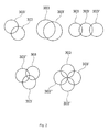
- FIG. 2 is an exemplified embodiment according to embodiments herein, not limiting of the scope of embodiments herein and shows different examples of placement of the circular shapes in the first step of the design method in relation to each other.
- FIG. 3 is an exemplified embodiment according to embodiments herein, not limiting of the scope of embodiments herein and shows an virtual implant placed in a knee.
- FIG. 4 a shows a pre-drilling guide socket.
- FIG. 4 b shows a drilling depth adjustment socket.
- FIG. 5 is an exemplified embodiment according to embodiments herein, not limiting of the scope of embodiments herein and shows an example where the circular shapes have varying diameters.
- FIG. 6 is an exemplified embodiment according to embodiments herein, not limiting of the scope of embodiments herein and showing a view after placement of the circular shapes and design of circular shapes with non-parallel axes.
- FIG. 7 is an exemplified embodiment according to embodiments herein, not limiting of the scope of embodiments herein and shows two circular shapes covering the bone and/or cartilage damage.
- FIGS. 8 a and 8 b is an exemplified embodiment according to embodiments herein, not limiting of the scope of embodiments herein and showing the virtual model of the implant placed at the implantation site and comprising a simulated cartilage surface 6 of the implant 1 which simulates the cartilage surface before the cartilage damage.
- FIG. 8 a is a view from one side and FIG. 8 b is virtual implant from above.
- FIG. 9 is an exemplified embodiment according to embodiments herein, not limiting of the scope of embodiments herein and showing a bone and cartilage damage wherein a simulated repair surface 16 is created which is a surface which preferably corresponds to a three dimensional 3D image of a simulated healthy cartilage surface.
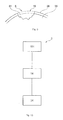
- FIG. 10 is an exemplifying flow chart of a method according to embodiments herein.
- FIG. 11A is an exemplified embodiment according to embodiments herein, not limiting of the scope of embodiments herein and showing placement of axes of two circular shapes in a joint with a cartilage and bone damage.
- FIG. 11B is an exemplified embodiment according to embodiments herein, not limiting of the scope showing the placement of the axes in relation to each other with an axe-distance and in relation to a simulated bone surface wherein the axes originate from a point of the simulated bone surface.
- a simulated cartilage surface for placement of the axes.
- FIG. 12 shows a two-pegged implant.
- FIG. 13 shows a rig according to one embodiment of embodiments herein for a two peg-implant.
- the rig is mounted in place.
- FIG. 14 a shows one embodiment of a three-pegged implant having the form of three identical intersecting circles.
- FIG. 14 b shows one embodiment of a rig with wall insert for a three-peg implant, seen from above.
- FIG. 15 shows an example of a double drill for use with the drilling rig according to embodiments herein.
- FIGS. 16A-16C show examples of cross-sections of a rig with inserts in accordance with embodiments herein.
- FIG. 16D shows an example of contours of cross-sections as defined by the rig and insert of FIG. 16B .
- Embodiments herein relates to a design method for design of an individually customized rig 600
- the rig 600 designed by the method according to embodiments herein is to be used for cartilage repair in a joint of a human or animal.
- the design method for design of an individually customized rig according to embodiments herein is described below.
- the rig comprises a hollow tubular shell, and the interior of the shell defines at least first and second intersecting cylinders.
- the design method comprises identifying a damage area, presenting a 3D view of the identified damage area and generating a 3D model of a virtual rig.
- the generating comprises virtually placing in 3D view a shape covering or partly covering damage area, and creating, based on the position of the virtually placed shape, a position of hollow tubular rig shell of the virtual rig.
- the method further comprises selecting the at least first and second intersecting cylinders of the virtual rig, based on the size and form of the virtually placed shape, and creating a positioning surface of the virtual rig which is a bone and/or cartilage-engaging end of the hollow tubular shell.
- the positioning surface is adapted to follow the surface surrounding the virtually placed shape when the virtual rig is placed in a virtual model of the joint.
- the method comprises producing a rig according to the virtually created rig.
- the design method for design of an individually customized rig 600 the rig 600 having a hollow tubular shell 510 open at both ends, characterized in that the interior of the shell defines at least first and second intersecting circular cylinders and wherein the design method for the rig 600 comprises the steps;
- Figure shows the design method according to embodiments herein comprising three general steps; A first damage identification step 101 , a second virtual model making step 14 , a third production step 34 ,
- the design method according to embodiments herein allows for producing a rig which is easy to fit to repair an individual damage in a patient.
- the circular shape build-up of the implant makes the rig also easy to place by drilling and/or reaming giving an exact fit of each implant in every patient.
- a first damage identification step 101 comprises identifying a bone and/or cartilage area 4 in a joint of a patient comprising a bone and/or cartilage damage 5 and presentation of a 3D view 9 of the identified area using a software program.
- the first damage identification step 101 in the design method according to embodiments herein is to identify the bone and/or cartilage area 4 in a joint of a specific patient whom is in need of bone and/or cartilage repair. This is done from 2D images such as MR images.
- a 3D view 9 of a joint comprising a bone and/or cartilage area 4 and/or comprising the bone and/or cartilage damage 5 is created by taking 2D images of the joint and converting them into a 3D view 9 .
- the bone and/or cartilage damage 5 can for example be identified in the 2D images which then are converted into a 3D view 9 ,
- Useful imaging techniques are for example Computed Tomography CT, Cone Beam Computed Tomography CBCT, Magnetic resonance imaging MM or other suitable techniques such as delayed Gadolinium-enhanced MRI of cartilage dGEMRIC techniques or the like,
- the taken 2D images of the joint are used to create a 3D model or view 9 of the patient's bone and/or cartilage and using for example a software program, for example a CAD animation program for example a radiography software program or the like is useful for 3D animation.
- a joint representation-CAD animation model is created which is a 3D view 9 comprising the bone and/or cartilage area 4 based on images from the joint. This model is further comprising the bone and/or cartilage damage 5 ,
- a damage-representation CAD animation model which shows the bone and/or cartilage damage 5 may be created manually from 2D images by manually marking out damaged area pixels in each 2D image and from that create a 3D view 9 or the damage-representation CAD animation model may be a combination of the marked up 2D images.
- a computer program for example a radiography software program, could be adapted to scan the images for predetermined characteristics of an area and/or spread, curvature and/or a location of bone and/or cartilage damage 2 in the image data and combine the automatically marked 2D images into a 3D view 9 also called the damage representation CAD animation model.
- a virtual 3D view 9 is a joint representation CAD animation model which can be selected to show the bone and/or cartilage area 4 , the bone and/or cartilage damage 5 , placement of virtual rig or virtual implant etc.
- a first damage identification step 101 of the design method according to embodiments herein comprises identifying a bone and/or cartilage area 4 in a patient by taking images of the injury or damage in the joint of a patient and then use these images of the individual patient's bone and/or cartilage area 4 to create a joint representation CAD animation model.
- FIG. 1 shows a 3D view 9 of a patient's knee joint comprising a bone and/or cartilage damage 5 wherein the borders around the bone and/or cartilage damage 18 are marked-up.
- Joints in a human or animal which may be repaired by using the rig designed according to the design method according to embodiments herein can be selected from for example any of a knee, hip, shoulder, toe or finger joint.
- FIG. 9 shows a 3D view 9 wherein a bone and/or cartilage damage is marked 5 and wherein a simulated cartilage repair surface 16 is marked out and wherein a simulated bone surface 51 is marked out and wherein the figure further comprises surrounding cartilage surface 36 and surrounding bone 35 .
- the second step 14 in the method according to embodiments herein comprises a first step of selecting a surface comprising at least two circular shapes 301 which decides upon how much the combined area 20 of the circular shapes 301 cover or partly cover the identified bone and/or cartilage damage 5 .
- This positioning data of the circular shapes 301 is used to create the position and interior of the hollow tubular rig shell 510 of the virtual rig which is open at both ends and wherein selection of at least first and second intersecting circular cylinders rig is based on the selected sizes of the circular shapes 303 , or slightly larger, and wherein a positioning surface 560 of the virtual rig is created which is a bone and/or cartilage-engaging end of the hollow tubular shell 510 and wherein the positioning surface 560 is adapted to face and align to the surface structure surrounding the hollow circular shapes of the rig when the rig is placed in a virtual model of the joint.
- the second step 14 in the method according to embodiments herein comprises virtually placing at least two points 19 each from where an axis 15 will origin, the points 19 are placed on the bone surface 50 of the joint in or nearby the area of the bone and/or cartilage damage 5 or the points 19 are placed on a simulated bone surface 51 which is a virtually created surface and covering the area of the bone and/or cartilage damage 5 ,
- the simulated bone surface 51 is a surface which preferably corresponds to a three dimensional 3D image of a bone surface in a healthy joint.
- the points 19 are surrounded by selected circular shapes 303 .
- the points 19 are centered in the circular shapes 301 , the circular shapes 303 , partly overlapping each other, and wherein the points 19 with the axes 15 are placed so that the combined area spread 20 of the circular shapes 303 covers or partly covers the identified bone and/or cartilage damage 5 .
- the axes 15 are placed with a selected axe-distance 53 from each other.
- the second step 14 in the method according to embodiments herein comprises a first selection of diameters 302 of the circular shapes 303 , selection of how much the circular shapes 303 should cover of the bone and/or cartilage damage 5 , selection of placement of axes 15 by selection of points 19 of intersection of the axes 15 on a simulated bone surface 51 or placement directly on a bone surface 50 in a 3D view of a joint.
- the diameter 302 of the circular shapes are selected simultaneously as the placement of the points 19 are made.
- Different types of selections may be comprised in the second virtual model making step 14 and are in one embodiment according to the design method according to embodiments herein selected in the following order. In other embodiments the first, second and third selections can be made in any order or can be made simultaneously;
- the first selections made in the second virtual model making step 14 according to embodiments herein can be made in any order or can be made simultaneously: and comprise
- FIG. 11A shows an exemplified embodiment according to embodiments herein, not limiting for the scope of embodiments herein, showing placement of axes of two circular shapes in a joint with a cartilage and bone damage
- the placement of the axes 15 and 15 ′ is shown in relation to each other with an axe-distance 53 See FIG. 11B and in relation to a simulated bone surface 51 wherein the axes 15 and 15 ′ originate from a point 19 of the simulated bone surface 51 and wherein the axes 15 and 15 ′ have an angle 25 , 25 ′ in relation to an bone-axis 60 which is normal in relation to an tangential plane 28 , 28 ′ of the simulated bone surface in the point 19
- FIGS. 11A and B further comprises cartilage 36 , bone 35 , bone surface 50 ,
- the height 710 of the hollow tubular rig shell 510 of the virtual rig is decided.
- the height of the hollow tubular shell 510 is selected depending on surrounding tissue and place of cartilage damage in order for ease of placement of the rig 600 during surgery and in order to have to make as little surgical intervention as possible.
- the height might be decided depending on where the implant is being placed.
- the height may vary depending on whether the implant is on for example the condylea or trochlea of a knee, being at least between 20-30 mm on the first and between at least 25-45 mm on the second. However a total variation of the height 710 between 10-90 mm is foreseen.
- the spread of an individually customized positioning surface 560 is also selected.
- the positioning surface 560 of the virtual rig is created which is a bone and/or cartilage-engaging end of the hollow tubular shell 510 and wherein the positioning surface 560 is adapted to face and align to the surface structure surrounding the hollow circular shapes of the rig when the rig is placed in a virtual model of the joint.
- the spread of the positioning surface 560 is selected depending on surrounding tissue and place of cartilage damage in order for ease of placement of the rig 600 during surgery and in order to have to make as little surgical intervention as possible.
- the spread is selected to cover an area in the joint with a curvature to guide the surgeon so that the rig 600 only can be placed in one way in the joint and thereby minimizing non-correct placement.
- the positioning surface 560 protrudes around the hollow tubular shell 510 so that the positioning surface gives the rig support during usage.
- the hollow tubular rig shell 510 of the virtually created rig should preferably have a height 710 of in between 10-90 mm, especially 20-30 mm for condylea and 25-45 mm for trochlea of a knee.
- the height of the hollow tubular rig shell 510 is decided upon by using the surfaces of the circular shapes 303 placed on a simulated bone surface 51 to create a cylindrical sphere presenting an elongation of a virtual view of the side wall of the circular shapes.
- the axe-distance 53 is between 6-32 or for example 7-20 or for example 7-12 mm.
- the axe-distance 53 is larger than 8 mm. In one embodiment according to embodiments herein the axe-distance 53 is 8 mm.
- the placements of the points 19 and/or axes 15 and/or the selection of diameters 302 of the circular shapes 303 are done manually by an operator using a software program or automatically by a software program.
- at least two axes 15 are parallel in relation to each other. However even if the two axes are parallel the angle between the surface of the cartilage and the axes is in this embodiment not 90 grades because of the curvature of the cartilage. In other embodiments the axes 15 have different angles in relation to each other and also in relation to a simulated bone surface 51 .
- FIG. 6 See for example FIG. 6 for an example according to embodiments herein wherein two circular shapes 303 are placed on a bone surface, with an overlap 301 and with non-parallel axes 15 and 15 ′ and also showing the surface 301 of the circular shapes 303 and 303 ′.
- the design method for design of an individually customized rig 600 comprises virtually placing at least two circular shapes 303 is performed by placing two circular shapes 303 so that the diameter of the circular shapes 303 has a 20-90% or 40-70% overlap 301 in relation to the diameter of each circle.
- the second virtual model making step 14 in the method according to one embodiment of embodiments herein comprises virtually placing at least two circular shapes 303 , partly overlapping, covering or partly covering the identified bone and/or cartilage damage 5 .
- FIG. 7 illustrates an example according to embodiments herein of the second virtual model making step 14 and comprises two virtually placed circular shapes 303 spread out over an implant area 20 covering the identified cartilage and/or bone damage 5 in a 3D view 9 .
- the second virtual model making step 14 in the design method according to embodiments herein comprises;
- Axis 15 has an angle 25 of 0-40 degrees in relation to a bone axis 60 which is normal in relation to a tangential plane 28 of the simulated bone surface 51 or in relation to the bone surface 51 in the point 19
- Axis 15 ′ has an angle 25 ′ of 0-40 degrees in relation to a bone-axis 60 ′ which is normal in relation to a tangential plane 28 of the simulated bone surface 51 in the point 19 ′ in a 3D view 9 of a virtually repaired articulate cartilage surface.
- the different axes 15 and 15 ′ of the circular shapes 303 have directions that are parallel to each other. In one embodiment the different axes 15 of the circular shapes 303 have different directions in relation to each other.
- the second step 14 in the method according to embodiments herein comprises of virtually placing at least two circular shapes 303 , partly overlapping, covering the identified bone and/or cartilage damage 5 ,
- the second step 14 in the method according to embodiments herein comprises of virtually placing at least two circular shapes 303 , partly overlapping, covering the identified bone and/or cartilage damage 5 and wherein all the circular shapes 303 have identical or approximately the same diameter.
- the second virtual model making step 14 in the method according to embodiments herein comprises of virtually placing at least two circular shapes 303 , partly overlapping, covering the identified bone and/or cartilage damage 5 and wherein the different circular shapes 303 have diameters in varying sizes, for example one with smaller diameter than another. See for example FIG. 5 wherein one circular shape 303 has one diameter 302 and another circular shape 303 ′ has a smaller diameter 302 ′ and wherein the both circular shapes has an overlap 301 .
- the second virtual model making step 14 in the method according to embodiments herein comprises of virtually placing at least two circular shapes 303 , partly overlapping, covering a part or covering the complete bone and/or cartilage damage 5 identified in images and presented in the 3D model of the bone and/or cartilage area 4 in the joint identified in the first step 101 of the design method according to embodiments herein.
- the combined area 20 of the overlapping circular shapes 303 together with a surrounding area giving space to the drilling socket will together define the area 20 of the implant body 30 to be produced.
- the area or cross section of the inside of the hollow tubular shell 510 means the sum of the spread of the shapes of the circular shapes 303 .
- the placement of the circular shapes 303 in relation to each other may be placement in a row or in symmetric groups or for example in an asymmetric order. For different examples of placement patterns of the circular shapes 303 see FIG. 2 .
- the placement pattern is selected depending on for example the placement of the bone and/or cartilage damage 5 , and/or the size of the bone and/or cartilage damage 5 and/or the spread of the bone and/or cartilage damage 5 and/or the depth of the bone and/or cartilage damage 5 .
- the overlap 301 of the circular shapes 303 is in one embodiment of embodiments herein performed so that the diameter of the circular shapes 303 has a 20-90% overlap 301 or for example 30-80% or for example 40-70% in relation to the diameter 302 of each overlapping circle.
- the overlap 301 of the circular shapes 303 is in one embodiment of embodiments herein performed so that the diameter of the circular shapes 303 has at least 40% overlap 301 in relation to the diameter of each overlapping circle.
- the diameters of the circular shapes 303 303 according to embodiments herein are between 5-30 mm or between 10-25 mm or for example between 15-25 mm.
- FIG. 3 shows one exemplified embodiment of embodiments herein
- FIG. 3 shows a virtual implant 42 placed in a knee and wherein the virtual implant 42 comprises two circular shapes 303 placed so that they have an overlap and further the axes 15 , 15 ′ of the circular shapes 303 , 303 ′ of the implant is parallel in this example.
- This implant is placed with help of the rig designed by the design method according to embodiments herein,
- FIGS. 8 a and 8 b shown exemplified embodiment according to embodiments herein, not limiting for the scope of embodiments herein, showing the virtual model of the implant 42 placed at the implantation site and comprising a simulated cartilage surface 41 of the virtual model of the implant 42 which mimics the cartilage surface before a cartilage damage.
- the virtual implant model 42 in the example in FIG. 8 a comprises a virtual implant body 30 and two extending post 23 , see FIG. 8 a.
- FIG. 8 a is a view from one side and FIG. 8 b is a view of a virtual model of the implant 42 from above and wherein the area 20 of the implant to be produced is shown.
- the rig according to embodiments herein may further comprise a wall insert 610 .
- the guide tool of the guide system according to embodiments herein comprises at least two guide holes or guide channels or openings to allow a in insert tool, for example a cutter or drill or rotary cutter, to pass through.
- the design of the wall insert 610 is in one embodiment a part of the design method according to embodiments herein, The wall insert 610 is used in order to support the insert tools so that the channel inside the hollow tubular shell 510 of the rig 600 supports the insert tools during usage of the rig.
- the insert tools are in one embodiment supported by parts of the walls of the guide channel inside the hollow tubular shell 510 in combination with a part of the sidewall of an wall insert 610 ,
- the wall insert 610 is a module which fits inside the guide channels by mimicking parts of the pattern of the guide channel inside area of the rig.
- the combination of parts of inside guide channel walls and part of sidewall of a wall insert 610 forms a round or cylindrical shaped guide hole, hereby called the active guide hole or guide channel.
- the active guide channel is a guide channel that may be used for insertion of insert tools at that time.
- the active guide channel is changed by moving around the wall insert 610 in the inside area of the guide channels. By moving around the wall insert 610 to guide or support another guide channel in the guide tool, new active guide channels are formed. It is also possible to use several inserts of different sizes in parallel instead of adjusting the insert during the work.
- the movable insert is not arcuate but is a cylinder.
- the wall insert 610 when placed in the rig channel, efficiently blocks guide channels not in use and the wall insert 610 forms, together with the inside walls of the active guide channel, a cylinder shaped wall around an active guide channel of the rig 600 ,
- Embodiments herein may comprise a design method for a rig and a wall insert 610 which together make the surgeon drill or cutter used inside the guide forming excision sites which correspond to an implant structure.
- the guide channels in the guide are adapted so that the formed excision sites are partially overlapping each other.
- implant shapes may be build selecting from different sizes of circular shapes 303 partly overlapping each other in combinations allows the surgeon to choose an implant which fits the size and shape of the cartilage damage or defect and gives the surgeon easy to use tool set for making the excisions needed.
- the design method according to embodiments herein involves a third production step 34 of producing a rig 600 .
- the third production step 34 comprises producing a rig 600 having the shape and volume as the virtual rig planned and created in first damage identification step 101 and the second virtual model making step 14 ,
- Polyamide rigs produced with selective laser sintering SLS are especially useful. Other production techniques and other materials are also possible. Other similar polymers such as polypropylene, polyethylene, polystyrene, poly-methylmetaacrylate PMMA, acrylonitrile butadiene styrene ABS and similar compounds can be used.
- the rig can also comprise any metal or metal alloy used for structural applications in the human or animal body, such as stainless steel, cobalt-based alloys, chrome-based alloys, titanium-based alloys, pure titanium, zirconium-based alloys, tantalum, niobium and precious metals and their alloys. If a ceramic is used, it can be a biocompatible ceramic such as aluminium oxide, silicon nitride or yttria-stabilized zirconia.
- the rig may contain parts that are made of other materials as well.
- FIG. 13 shows an example of one embodiment of a rig according to embodiments herein which is used for all of the hole preparation.
- the rig comprises an elongated hollow shell 510 having the form of two intersecting overlapping circular cylinders 52 , 53 of the same diameter and the hollow tubular rig shell 510 has a height 710 between 10-90 mm.
- the rig 600 can be formed to conform to the shape of the bone and cartilage area of the patient to be repaired or can be a standard rig.
- the rig is held securely in place on the condylar surface in this case by individually customized the positioning surface 560 and with pins not shown driven in through holes 61 , to hold the rig securely in place throughout the entire drilling process.
- the cutting and drilling process can begin, with a wall insert 610 inserted in one end of the hollow shell, leaving an entire first circular cylinder 52 at one end of the hollow tubular shell.
- the surgeon may insert into the first circular cylinder a depth adjustment socket 505 FIG. 4 b and then a sharp cylindrical hand knife, sized exactly to the interior of the adjustment socket 505 , makes a preliminary circular sharp edged cut through the cartilage down to the bone. A circular bare bone area is left after this cartilage removal.
- the surgeon uses a 17/4 mm double drill as shown schematically in FIG. 15 . It has a central narrow 4 mm diameter bit 401 , and a wider 17 mm diameter cutting bit 402 ,
- the outer lateral surface 403 of the double drill conforms to the circular cylinder, which securely holds the double drill to drill, in the same operation, a central 4 mm hole for the first peg 23 and a much shallower surrounding bore 17 mm in diameter in this example.
- a pre-drilling of the initial part of the peg hole in the bone can according to one embodiment be made using a guide socket 501 FIG. 4 a , This improves the exact placement of the simultaneous drilling of the peg hole and the circular bare-bone area with the double drill FIG. 15 , After removing the drill, and flushing out organic matter, the surgeon then slides the wall insert 610 out and inserts it in on the other side of the hollow shell, creating a complete circular cylindrical guide hole on the opposite side of the hollow shell.
- the in this embodiment 17/4 mm double drill is then used again first with the guide socket 501 to pre-drill the peg hole and then with the adjustment socket 505 to double-drill the peg hole to its full depth and create the bare-bone circle, i.e. the 4 mm hole for the second peg and a second surrounding shallow bore which is of course also 17 mm in diameter.
- the first, slightly thicker peg, is tapped down into its hole while the second peg, slightly narrower, slides easily into its hole.
- the larger diameter part of the 17/4 mm drill in this example has a rim to excavate a peripheral slot slightly deeper than the 17 mm shallow cavity, to accommodate the peripheral ridge 47 of the implant, helping to hold the implant securely in place during healing and subsequent loading during use.
- the rig which can be form-fitted to the shape of the individual patient's cartilage surface in this example, is placed over the damaged area of the condyle and is anchored securely in place, in this particular non-limiting example, by driving in four pins not shown into holes 61 in the condyle shaped lower end of the rig 600 , It is now securely in place for the entire drilling operation, which be simplified greatly and made much more exact and less dependent on the artistry of the surgeon, which may vary from day to day.
- the pins are pulled out and the rig is removed from the site, for implantation of the implant and reconstitution of the joint with the new implant.
- the rig as claimed can be supplemented with an insert sleeve to make one of the circular cylinders of a small diameter, e.g. from 17 to mm in diameter, to accommodate an implant having the form of two intersecting circles of slightly different diameters, for example +17 millimeters.
- a small diameter e.g. from 17 to mm in diameter
- an implant having the form of two intersecting circles of slightly different diameters for example +17 millimeters.
- rigs with a specific predecided fixed diameter may be prepared.
- an implant in the form of three, or more, intersecting circles to cover bone damage of more irregular shape.
- One such three-circle implant 101 is shown from below in FIG. 14 a showing three pegs 148 , 149 and 150 ,
- peg 148 has an interference fit diameter in relation to the common nominal diameter of all three pegs and the other two pegs 149 and 150 have clearance fit diameters in relation to the common nominal diameter.
- the rig for this three-circle implant is shown from above in FIG. 14 b .
- the rig is held in place on the bone by pins not shown inserted through holes 161 ,
- the wall insert 610 completes the first circular cylinder 152 covering the remaining portions of the other two circular cylinders.
- the wall insert 610 is pulled out, rotated 120 degrees and is inserted again to provide a drill guide for the next circle drilling with the same double drill, which in one embodiment can be the same 17/4 drill used together with the two-circle rig.
- a three pegged implant is inserted.
- this insert has one peg which is of interference fit dimension in relation to its nominal diameter in this case 4 mm and the other two pegs are of clearance fit.
- FIG. 15 shows an exemplary 4/17 double drill for use with the multiple circle rigs described above or with a previously known single circle rig,
- the double drill has a 4 mm central bit 401 for creating the hole for the peg and a wider cutting surface 402 for creating the 17 mm shallow hole.
- One of the advantages of embodiments herein is that the same double drill can be used for single, double or triple or more intersecting circle shaped implants, used twice or three times as the case may be for the two embodiments shown here. According to the example in FIG. 17 the hole is more shallow then the peg. According to other examples it could also be deeper than the peg.
- FIGS. 16A-16C show examples of cross-sections of a rig with inserts in accordance with embodiments described herein.
- FIG. 16A-16C show examples of a cross-section of an embodiment of the hollow tubular shell 510 of a rig with an insert 610 configured to define a cylinder having a cross-section 152 .
- the insert 610 defines the first cylinder.
- the insert 610 is taken out, turned 180 degrees and inserted again in the shell 510 it defines the second cylinder.
- the interior cross-section of the shell and the cross-section of the insert are elliptic. In FIG.
- the cross-section of the cylinders is defined by a bore in the insert 610 .
- a segment of the cross-section of the cylinder defining bore is part of the shell 510 and the other segment is part of the insert 610 .
- the interior cross-section of the shell 510 and the cross-section of the insert are rectangular.
- other cross-sections preferably are provided or conceivable, e.g. symmetrical, partly symmetrical or non-symmetrical cross-sections.
- FIG. 16D shows an example of contours of cross-sections as defined by the rig and insert of FIG. 16B .
- FIG. 12 shows an exemplified embodiment of an implant 1 according to embodiments herein, having two circular shapes, having two extending posts 23 , 23 ′ or pegs and a protruding edge 47 surrounding the implant body 30 ,
- This example is directed to an example wherein the two circular shapes have the same diameters.
Landscapes
- Health & Medical Sciences (AREA)
- Life Sciences & Earth Sciences (AREA)
- Surgery (AREA)
- Engineering & Computer Science (AREA)
- Orthopedic Medicine & Surgery (AREA)
- Veterinary Medicine (AREA)
- Animal Behavior & Ethology (AREA)
- Public Health (AREA)
- General Health & Medical Sciences (AREA)
- Biomedical Technology (AREA)
- Heart & Thoracic Surgery (AREA)
- Oral & Maxillofacial Surgery (AREA)
- Transplantation (AREA)
- Nuclear Medicine, Radiotherapy & Molecular Imaging (AREA)
- Medical Informatics (AREA)
- Molecular Biology (AREA)
- Cardiology (AREA)
- Vascular Medicine (AREA)
- Dentistry (AREA)
- Physical Education & Sports Medicine (AREA)
- Robotics (AREA)
- Rheumatology (AREA)
- Biophysics (AREA)
- Prostheses (AREA)
- Surgical Instruments (AREA)
Abstract
Description
-
- Providing a method for cartilage replacement wherein an implant is firmly attached in the joint and is well integrated into the surface structure of the joint, in order to generate optimal repair of damaged tissue and cause minimum damage to the surrounding tissue.
- Providing a design method for a rig to be used for positioning of an implant to be implanted in the joint, improving the positioning of the implant in order to generate optimal repair of damaged tissue and cause minimum damage to the surrounding tissue and aiding the surgeon in that positioning.
- Providing an individual design of a rig.
-
- identifying (101) a damage area (4) in said joint;
- presenting a 3D view (9) of said identified damage area (4) in a virtual model of the joint;
- generating a 3D model of a virtual rig, wherein the generating comprises virtually placing in said 3D view (9) a shape (303) at least partly covering said damage area (4) in said virtual model of the joint;
- creating, based on the position of the virtually placed shape (303), a position of said hollow tubular shell (510) of the virtual rig;
- selecting the at least first and second intersecting cylinders of the virtual rig, based on the size and form of the virtually placed shape (303);
- creating a positioning surface (560) of the virtual rig as a bone and/or cartilage engaging end of said hollow tubular shell (510) and which positioning surface (560) is adapted to follow the surface of the joint surrounding the virtually placed shape when the virtual rig is placed in the virtual model of the joint;
- producing a rig (600) according to the virtual rig.
-
- a circular cross-section;
- an elliptic cross-section;
- a rectangular cross section;
- a triangular cross-section;
and/or other symmetric, partially symmetric or non-symmetric cross-section.
-
- A first
damage identification step 101 comprising identifying a bone and/or cartilage area 4 in a patient comprising a bone and/orcartilage damage 5 and presentation of a 3D view 9 of the identified area using a software program - A second virtual
model making step 14 comprising making a 3D model of a virtual rig comprising a step of virtually placing in the 3D view 9 at least twocircular shapes 303, wherein eachcircular shape 303 partly overlaps at least one othercircular shape 303′, and wherein the combinedarea 20 of the circular shapes covers or partly covers the identified bone and/orcartilage damage 5 and wherein positioning data is used to create the position and interior of the hollowtubular rig shell 510 of the virtual rig which is open at both ends and wherein selection of at least first and second intersecting circular cylinder rig is based on the selected sizes of thecircular shapes 303, or slightly larger, and wherein apositioning surface 560 of the virtual rig is created which is a bone and/or cartilage-engaging end of the hollowtubular shell 510 and wherein thepositioning surface 560 is adapted to face and align to the surface structure surrounding the hollow circular shapes of the rig when the rig is placed in a virtual model of the joint. - A
third production step 34 comprising producing arig 600 according to the virtually created rig which is adapted to mimic the volume and shape according to the created virtual model of the rig.
- A first
-
- placing at least two
points 19 each from where anaxis 15 will origin from, thepoints 19 are placed on thebone surface 50 in the 3D view 9 of the joint in or nearby the area of the bone and/orcartilage damage 5 or thepoints 19 are placed on a simulated bone surface which is a virtually created surface in or nearby the area of the bone and/orcartilage damage 5 - selecting axe-
distance 53 - selecting diameter of circular shapes, the
diameter 302 of thecircular shapes 303 are selected between 10-30 mm or for example 15-25 mm - selecting coverage of the
implant area 20 over the cartilage and/orbone damage 5, wherein the coverage may be between 50-100% and wherein a second selection step comprises; - Selection of the
angles 25 of theaxes 15 which originate from apoint 19 of thesimulated bone surface 51 and wherein theaxes angle 25 0-40 degrees in relation to a bone-axis 60 which is normal in relation to atangential plane 28 of the simulated bone surface in thatpoint 19,
- placing at least two
-
- a rig (600) having a guide body in the form of a hollow tubular shell (510) configured to define at least first and second intersecting cylinders;
- a positioning surface (560) of the virtual rig being a bone and/or cartilage engaging end of said hollow tubular shell (510) and which positioning surface (560) is adapted to follow the surface of the joint surrounding an identified damage area in said joint.
-
- a circular cross-section;
- an elliptic cross-section;
- a rectangular cross section;
- a triangular cross-section;
and/or other symmetric, partially symmetric or non-symmetric cross-section.
-
- the diameters (302) of the cylinders are selected between 10-30 mm or for example 15-25 mm; and/or
- a coverage, by the cross-section of said intersecting, cylinders of an implant area (20) over a cartilage and/or bone damage (5) is between 50-100%, and/or
- axes (15) and (15′) of said cylinders have an angle (25) 0-40 degrees in relation to a bone-axis (60) which is normal in relation to a tangential plane (28) of the bone surface.
-
- A first
damage identification step 101 comprising identifying a bone and/or cartilage area 4 in a patient comprising a bone and/orcartilage damage 5 and presentation of a 3D view 9 of the identified area using a software program - A second virtual
model making step 14 comprising making a 3D model of a virtual rig comprising a step of virtually placing in the 3D view 9 at least twocircular shapes 303, wherein eachcircular shape 303 partly overlapping at least one othercircular shape 303′, and wherein the combinedarea 20 of the circular shapes cover or partly cover the identified bone and/orcartilage damage 5 and wherein these positioning data is used to create the position and interior of the hollowtubular rig shell 510 of the virtual rig which is open at both ends and wherein selection of least first and second intersecting circular cylinders rig is based on the selected sizes of thecircular shapes 303, or slightly larger, and wherein apositioning surface 560 of the virtual rig is created which is a bone and/or cartilage-engaging end of the hollowtubular shell 510 and wherein thepositioning surface 560 is adapted to face and align to the surface structure surrounding the hollow circular shapes of the rig when the rig is placed in a virtual model of the joint. - A
third production step 34 comprising producing arig 600 according to the created virtually created rig which is adapted to mimic the volume and shape according to the created virtual model of the rig.
- A first
-
- placing at least two
points 19 each from where anaxis 15 will origin from, thepoints 19 are placed on thebone surface 50 of the joint in or nearby the area of the bone and/orcartilage damage 5 or thepoints 19 are placed on asimulated bone surface 51 which is a virtually created surface and covering the area of the bone and/orcartilage damage 5 - selecting diameter of circular shapes, the
diameter 302 of thecircular shapes 303 are selected between 10-30 mm or for example 15-25 mm; - wherein the axe-
distance 53 between thepoints 19 is for example between 6-32 mm or 7-20 mm or 7-12 mm; - selecting coverage of the implant area 7 over the cartilage and/or
bone damage 5. The coverage is preferably 100% but may be between 50-100%.
Second Selections; - Selection of the
angles 25 of theaxes 15.Angles 25 in relation tosimulated bone surface
- placing at least two
-
- virtually placing at least two
circular shapes 303, partly overlapping, covering or partly covering the identified cartilage and/orbone damage 5 and - virtually creating at least two directions of at least two
circular shapes 303 in relation to the identified cartilage and/or bone area 4.
- virtually placing at least two
Claims (17)
Applications Claiming Priority (4)
| Application Number | Priority Date | Filing Date | Title |
|---|---|---|---|
| WOPCT/EP2014/064760 | 2014-07-09 | ||
| PCT/EP2014/064760 WO2016004992A1 (en) | 2014-07-09 | 2014-07-09 | A surgical joint implant and a bone-mountable rig |
| EPPCT/EP2014/064760 | 2014-07-09 | ||
| PCT/EP2015/065780 WO2016005541A1 (en) | 2014-07-09 | 2015-07-09 | Design method of a rig |
Publications (2)
| Publication Number | Publication Date |
|---|---|
| US20170156890A1 US20170156890A1 (en) | 2017-06-08 |
| US10470886B2 true US10470886B2 (en) | 2019-11-12 |
Family
ID=51205363
Family Applications (2)
| Application Number | Title | Priority Date | Filing Date |
|---|---|---|---|
| US15/324,379 Abandoned US20170172744A1 (en) | 2014-07-09 | 2014-07-09 | Surgical joint implant and a bone-mountable rig |
| US15/324,437 Active 2036-04-10 US10470886B2 (en) | 2014-07-09 | 2015-07-09 | Method of a rig |
Family Applications Before (1)
| Application Number | Title | Priority Date | Filing Date |
|---|---|---|---|
| US15/324,379 Abandoned US20170172744A1 (en) | 2014-07-09 | 2014-07-09 | Surgical joint implant and a bone-mountable rig |
Country Status (8)
| Country | Link |
|---|---|
| US (2) | US20170172744A1 (en) |
| EP (3) | EP3166540B1 (en) |
| JP (1) | JP6523424B2 (en) |
| CN (2) | CN106714736B (en) |
| AU (1) | AU2015286600B2 (en) |
| CA (1) | CA2954353C (en) |
| ES (1) | ES2846759T3 (en) |
| WO (2) | WO2016004992A1 (en) |
Families Citing this family (15)
| Publication number | Priority date | Publication date | Assignee | Title |
|---|---|---|---|---|
| US10603049B2 (en) | 2011-09-02 | 2020-03-31 | Episurf Ip-Management Ab | Implant specific drill bit in surgical kit for cartilage repair |
| US11000387B2 (en) | 2011-09-02 | 2021-05-11 | Episurf Ip-Management Ab | Implant for cartilage repair |
| ES2902455T3 (en) | 2013-04-15 | 2022-03-28 | Episurf Ip Man Ab | Implant comprising a positioning mark |
| US20190231538A1 (en) * | 2013-04-15 | 2019-08-01 | Episurf Ip-Management Ab | Method of designing and positioning a medical implant and an implant comprising a positioning mark |
| WO2016004991A1 (en) | 2014-07-09 | 2016-01-14 | Episurf Ip-Management Ab | Customized implant for cartilage repair and corresponding method of design |
| US20170172744A1 (en) | 2014-07-09 | 2017-06-22 | Episurf Ip-Management Ab | Surgical joint implant and a bone-mountable rig |
| DK3181050T3 (en) | 2015-12-18 | 2020-05-11 | Episurf Ip Man Ab | System and method for forming a decision support material indicating damage to an anatomical joint |
| US11526988B2 (en) | 2015-12-18 | 2022-12-13 | Episurf Ip-Management Ab | System and method for creating a decision support material indicating damage to an anatomical joint |
| US11250561B2 (en) | 2017-06-16 | 2022-02-15 | Episurf Ip-Management Ab | Determination and visualization of damage to an anatomical joint |
| CN109966029A (en) * | 2017-12-28 | 2019-07-05 | 财团法人工业技术研究院 | Cartilage repair carrier, matched surgical instrument set and cartilage repair system |
| US10786370B2 (en) | 2017-12-28 | 2020-09-29 | Industrial Technology Research Institute | Cartilage repair implant, auxiliary surgical tool kit and cartilage repair system |
| WO2019245854A2 (en) | 2018-06-19 | 2019-12-26 | Tornier, Inc. | Extended reality visualization of range of motion |
| US11645749B2 (en) | 2018-12-14 | 2023-05-09 | Episurf Ip-Management Ab | Determination and visualization of damage to an anatomical joint |
| EP4076257A1 (en) | 2019-12-18 | 2022-10-26 | Howmedica Osteonics Corporation | Surgical guidance for surgical tools |
| SE2151181A1 (en) * | 2021-09-27 | 2023-03-28 | Metatarsal implant |
Citations (99)
| Publication number | Priority date | Publication date | Assignee | Title |
|---|---|---|---|---|
| US4180910A (en) | 1977-10-31 | 1980-01-01 | Institut Straumann Ag | Implant for an artificial tooth |
| US4197645A (en) | 1976-07-06 | 1980-04-15 | Scheicher Hans M F | Drill head and bone drill |
| US4964865A (en) | 1988-02-03 | 1990-10-23 | Intermedics Orthopedics, Inc. | Glenoid prosthesis and method of use |
| WO1994009730A1 (en) | 1992-10-27 | 1994-05-11 | Smith & Nephew Richards Inc. | Orthopaedic cutting instrument and prosthetic device |
| US5520692A (en) | 1995-02-28 | 1996-05-28 | Wright Medical Technology, Inc. | Adjustable depth patella recessing guide and method |
| WO1996024302A1 (en) | 1995-02-07 | 1996-08-15 | Matrix Biotechnologies, Inc. | Surgical implantation of cartilage repair unit |
| US5716360A (en) | 1995-06-30 | 1998-02-10 | U.S. Medical Products | Patella recession instrument and method for anatomically-shaped patellar prostheses |
| US5743916A (en) | 1990-07-13 | 1998-04-28 | Human Factors Industrial Design, Inc. | Drill guide with removable ferrules |
| JPH10504217A (en) | 1995-02-07 | 1998-04-28 | マトリックス・バイオテクノロジーズ・インコーポレイテッド | Surgical implantation of a cartilage repair unit |
| US5976147A (en) | 1997-07-11 | 1999-11-02 | Johnson & Johnson Professional, Inc | Modular instrumentation for bone preparation and implant trial reduction of orthopedic implants |
| US6063091A (en) | 1998-10-13 | 2000-05-16 | Stryker Technologies Corporation | Methods and tools for tibial intermedullary revision surgery and associated tibial components |
| US6165177A (en) | 1998-12-24 | 2000-12-26 | Depuy Orthopaedics, Inc. | Alignment guide for insertion of stem prosthesis |
| US6251143B1 (en) | 1999-06-04 | 2001-06-26 | Depuy Orthopaedics, Inc. | Cartilage repair unit |
| US6306142B1 (en) | 1998-07-17 | 2001-10-23 | Johnson & Johnson | Method and apparatus for harvesting and implanting bone plugs |
| US20020095214A1 (en) | 2001-01-16 | 2002-07-18 | Hyde Edward R. | Transosseous core approach and instrumentation for joint replacement and repair |
| US20020116006A1 (en) | 2001-02-21 | 2002-08-22 | Herb Cohen | Instrumentation and method for implant insertion |
| US20030018337A1 (en) | 2001-07-17 | 2003-01-23 | Davis Reginald J. | Bone drill and tap combination |
| US6520964B2 (en) | 2000-05-01 | 2003-02-18 | Std Manufacturing, Inc. | System and method for joint resurface repair |
| US20030100947A1 (en) | 1999-12-15 | 2003-05-29 | Daniel Nadler | Preparation for repairing cartilage defects or cartilage/bone defects in human or animal joints |
| US20030144741A1 (en) | 2002-01-28 | 2003-07-31 | Richard King | Composite prosthetic bearing having a crosslinked articulating surface and method for making the same |
| US20030216669A1 (en) | 2001-05-25 | 2003-11-20 | Imaging Therapeutics, Inc. | Methods and compositions for articular repair |
| US20040098133A1 (en) * | 2000-03-17 | 2004-05-20 | Roger Carignan | Custom replacement device for resurfacing a femur and method of making the same |
| US20040147927A1 (en) * | 2002-11-07 | 2004-07-29 | Imaging Therapeutics, Inc. | Methods for determining meniscal size and shape and for devising treatment |
| US6799066B2 (en) | 2000-09-14 | 2004-09-28 | The Board Of Trustees Of The Leland Stanford Junior University | Technique for manipulating medical images |
| US20040215203A1 (en) | 1996-07-31 | 2004-10-28 | Michelson Gary K. | Bone removal device |
| US20050209694A1 (en) | 2004-03-12 | 2005-09-22 | Loeb Marvin P | Artificial spinal joints and method of use |
| US20050234467A1 (en) | 2004-03-08 | 2005-10-20 | James Rains | Screw guide |
| WO2006091686A2 (en) | 2005-02-22 | 2006-08-31 | Arthrosurface, Inc. | Articular surface implant |
| EP1698307A1 (en) | 2005-03-03 | 2006-09-06 | Karl Storz GmbH & Co. KG | Medical instrument for autologous chondrocyte transplantation |
| US20060206208A1 (en) | 1999-05-05 | 2006-09-14 | Sdgi Holdings, Inc. | Push-in interbody spinal fusion implant with multi-lock for locking opposed screws and method for use thereof |
| US20060235539A1 (en) | 2003-02-03 | 2006-10-19 | Gordon Blunn | Surgical kit for hemiarthroplasty hip replacement |
| US20060247790A1 (en) | 2005-04-30 | 2006-11-02 | Mckay William F | Shaped osteochondral grafts and methods of using same |
| US20070021838A1 (en) | 2005-07-22 | 2007-01-25 | Dugas Jeffrey R | Site specific minimally invasive joint implants |
| US20070100459A1 (en) | 2005-10-27 | 2007-05-03 | Rhodes James M | Method of repairing a knee joint |
| US20070159487A1 (en) | 2003-07-21 | 2007-07-12 | Felt Adam C | Processing image data |
| US20070233150A1 (en) | 2006-03-30 | 2007-10-04 | Jason Blain | Drill guide with rotating handle |
| EP1753365B1 (en) | 2004-05-04 | 2007-10-17 | OBL (Société Anonyme) | Custom-fit implantable surgical guide and associated milling tool, method for the production of the same |
| US20070276501A1 (en) | 2006-05-25 | 2007-11-29 | Spinemedica Corp. | Patient-specific spinal implants and related systems and methods |
| EP1864629A2 (en) | 2006-06-07 | 2007-12-12 | Howmedica Osteonics Corp. | Flexible joint implant |
| US20080051793A1 (en) | 2006-08-04 | 2008-02-28 | David Erickson | Drill-tap tool |
| WO2008098061A2 (en) | 2007-02-06 | 2008-08-14 | Arthrosurface Incorporated | System and method for joint resurface repair |
| WO2008101090A2 (en) | 2007-02-14 | 2008-08-21 | Conformis, Inc. | Implant device and method for manufacture |
| US20080243127A1 (en) | 2001-05-25 | 2008-10-02 | Conformis, Inc. | Surgical Tools for Arthroplasty |
| WO2008138137A1 (en) | 2007-05-14 | 2008-11-20 | Queen's University At Kingston | Patient-specific surgical guidance tool and method of use |
| US20090209962A1 (en) * | 2008-02-12 | 2009-08-20 | Amir Jamali | Device and method for allograft and tissue engineered osteochondral graft surface matching, preparation, and implantation |
| WO2009108591A1 (en) | 2008-02-28 | 2009-09-03 | Schwartz Biomedical, Llc | Partial joint resurfacing implant, instrumentation, and method |
| WO2009111626A2 (en) | 2008-03-05 | 2009-09-11 | Conformis, Inc. | Implants for altering wear patterns of articular surfaces |
| US20090270868A1 (en) | 2008-04-29 | 2009-10-29 | Otismed Corporation | Generation of a computerized bone model representative of a pre-degenerated state and useable in the design and manufacture of arthroplasty devices |
| US20090318927A1 (en) | 2008-06-23 | 2009-12-24 | Martin Troy D | Adjustable drill guide |
| US7658879B2 (en) | 2003-02-20 | 2010-02-09 | Medtronic, Inc. | Trajectory guide with angled or patterned guide lumens or height adjustment |
| US7713305B2 (en) | 2000-05-01 | 2010-05-11 | Arthrosurface, Inc. | Articular surface implant |
| US20100185201A1 (en) | 2007-09-12 | 2010-07-22 | Imagnosis Inc. | Implant erecting drill toll, hand-piece, adaptor for the hand-piece, and surgical guide |
| WO2010099357A1 (en) | 2009-02-25 | 2010-09-02 | Arthrosurface Incorporated | Trochlear resurfacing system and method |
| US20100234850A1 (en) | 2005-02-01 | 2010-09-16 | Smith And Nephew, Inc. | Lockable Orientation Instrument Assembly |
| US7867234B2 (en) | 2003-10-06 | 2011-01-11 | Howmedica Osteonics Corp. | Reamer bushing |
| US20110029093A1 (en) | 2001-05-25 | 2011-02-03 | Ray Bojarski | Patient-adapted and improved articular implants, designs and related guide tools |
| US20110054483A1 (en) | 2009-08-28 | 2011-03-03 | Zimmer Dental, Inc. | Device for limiting the drilling depth of a drill |
| US20110087332A1 (en) | 2001-05-25 | 2011-04-14 | Ray Bojarski | Patient-adapted and improved articular implants, designs and related guide tools |
| WO2011063257A1 (en) | 2009-11-20 | 2011-05-26 | Knee Creations, Llc | Instruments for targeting a joint defect |
| CN102083374A (en) | 2008-03-31 | 2011-06-01 | 奥利克拉奈尔有限公司 | Intramedullary device assembly and associated method |
| US20110152869A1 (en) | 2000-05-01 | 2011-06-23 | Arthrosurface, Inc. | Bone Resurfacing System and Method |
| US20110166661A1 (en) | 2007-01-30 | 2011-07-07 | Tornier Sas | Apparatus for fitting a shoulder prosthesis |
| US7981122B2 (en) | 2006-07-24 | 2011-07-19 | Vanderbilt University | Adjustable surgical platform and surgical instrument using same |
| US20110238071A1 (en) | 2010-03-24 | 2011-09-29 | Alain Fernandez-Scoma | Drill assistance kit for implant hole in a bone structure |
| US8066708B2 (en) | 2001-05-25 | 2011-11-29 | Conformis, Inc. | Patient selectable joint arthroplasty devices and surgical tools |
| EP2389905A1 (en) | 2010-05-24 | 2011-11-30 | Episurf Medical AB | Method of designing a surgical kit for cartilage repair in a joint |
| EP2389899A1 (en) | 2010-05-24 | 2011-11-30 | Episurf Medical AB | System of manufacturing a surgical kit for cartilage repair in a joint |
| US20120053588A1 (en) | 2010-08-31 | 2012-03-01 | Lozier Antony J | Drill bit for osteochondral drilling with guiding element and uses thereof |
| US20120150030A1 (en) | 2009-07-15 | 2012-06-14 | Accelerated Orthopedic Technologies, Inc. | Instruments, Methods and Systems for Harvesting and Implanting Cartilage Material |
| US20120209394A1 (en) | 1997-01-08 | 2012-08-16 | Conformis, Inc. | Patient-Adapted and Improved Articular Implants, Designs and Related Guide Tools |
| WO2012129018A1 (en) | 2011-03-18 | 2012-09-27 | Depuy Products, Inc. | Combination reamer/drill bit for shoulder arthroplasty |
| US20120271417A1 (en) | 2000-05-01 | 2012-10-25 | Arthrosurface Incorporated | System and Method for Joint Resurface Repair |
| WO2012143531A1 (en) | 2011-04-21 | 2012-10-26 | Episurf Medical Ab | Guide tool for cartilage repair |
| US20120316565A1 (en) | 2008-02-27 | 2012-12-13 | Ilion Medical Llc | Tools for performing less invasive orthopedic joint procedures |
| US20120330317A1 (en) * | 2011-06-27 | 2012-12-27 | Biomet Sports Medicine, Llc | Method for Repairing Bone Defects |
| US20120330316A1 (en) | 2011-06-27 | 2012-12-27 | Biomet Sports Medicine, Llc | Apparatus for Repairing Bone Defects |
| WO2013030371A9 (en) | 2011-09-02 | 2013-05-23 | Episurf Medical Ab | Implant specific drill bit |
| US20130165939A1 (en) | 2011-02-14 | 2013-06-27 | Imds Corporation | Patient Specific Implants and Instrumentation For Patellar Prostheses |
| US20130172891A1 (en) * | 2010-05-24 | 2013-07-04 | Episurf Medical Ab | Surgical kit for cartilage repair comprising implant and a set of tools |
| US20130184820A1 (en) | 2008-02-28 | 2013-07-18 | Biopoly, Llc | Partial joint resurfacing implant, instrumentation, and method |
| US20130211410A1 (en) | 2012-02-07 | 2013-08-15 | Conformis, Inc. | Patella Resection Instrument Guide Having Optional Patient-Specific Features |
| US20130211531A1 (en) | 2001-05-25 | 2013-08-15 | Conformis, Inc. | Patient-adapted and improved articular implants, designs and related guide tools |
| US8641721B2 (en) | 2011-06-30 | 2014-02-04 | DePuy Synthes Products, LLC | Customized patient-specific orthopaedic pin guides |
| US20140208578A1 (en) * | 2011-08-15 | 2014-07-31 | Conformis, Inc. | Revision Systems, Tools and Methods for Revising Joint Arthroplasty Implants |
| US20140277522A1 (en) | 2013-03-15 | 2014-09-18 | Imds Corporation | Humeral arthroplasty |
| US8882818B1 (en) | 2012-09-24 | 2014-11-11 | Vg Innovations, Llc | Method for deploying a fusion device for sacroiliac joint fusion |
| US8945135B2 (en) * | 2011-02-14 | 2015-02-03 | Michael D. Ries | Patellar prostheses and instrumentation |
| US20150190151A1 (en) | 2012-04-04 | 2015-07-09 | Smith & Nephew, Inc. | Surgical guide with intraoperative depth feedback |
| US20150230874A1 (en) | 2010-08-25 | 2015-08-20 | Suraj Ravi Musuvathy | Personalized orthopedic implant cad model generation |
| US20150320429A1 (en) | 2006-02-27 | 2015-11-12 | Biomet Manufacturing, Llc | Patient-Specific Elbow Guides And Associated Methods |
| US9216089B2 (en) | 2013-03-13 | 2015-12-22 | Depuy (Ireland) | Method of surgically preparing a patient's tibia |
| US20160089159A1 (en) | 2014-09-30 | 2016-03-31 | Medos International Sàrl | Surgical Guide for Use in Ligament Repair Procedures |
| US20160100847A1 (en) * | 2014-10-13 | 2016-04-14 | Biomet Sports Medicine, Llc | Patello-Femoral With Reusable Instruments |
| US20160151076A1 (en) | 2011-09-02 | 2016-06-02 | Episurf Ip-Management Ab | Implant specific drill bit in surgical kit for cartilage repair |
| US9386999B2 (en) | 2013-03-13 | 2016-07-12 | Depuy (Ireland) | Tibial orthopaedic surgical instruments for setting offset |
| US20160199075A1 (en) | 2013-06-28 | 2016-07-14 | Episurf Ip-Management Ab | Guide tool for bone and/or cartilage repair or joint remodeling |
| US20170100253A1 (en) | 2011-09-02 | 2017-04-13 | Episurf Ip-Management Ab | Design of an implant for cartilage repair |
| US20170172747A1 (en) | 2014-07-09 | 2017-06-22 | Episurf Ip-Management Ab | Surgical kit for cartilage repair comprising implant and a set of tools |
| US20170172744A1 (en) | 2014-07-09 | 2017-06-22 | Episurf Ip-Management Ab | Surgical joint implant and a bone-mountable rig |
Family Cites Families (1)
| Publication number | Priority date | Publication date | Assignee | Title |
|---|---|---|---|---|
| GB0803514D0 (en) * | 2008-02-27 | 2008-04-02 | Depuy Int Ltd | Customised surgical apparatus |
-
2014
- 2014-07-09 US US15/324,379 patent/US20170172744A1/en not_active Abandoned
- 2014-07-09 WO PCT/EP2014/064760 patent/WO2016004992A1/en not_active Ceased
- 2014-07-09 EP EP14739390.4A patent/EP3166540B1/en not_active Not-in-force
-
2015
- 2015-07-09 CN CN201580048028.5A patent/CN106714736B/en active Active
- 2015-07-09 JP JP2017500881A patent/JP6523424B2/en active Active
- 2015-07-09 ES ES18189755T patent/ES2846759T3/en active Active
- 2015-07-09 EP EP15738045.2A patent/EP3166542B1/en not_active Not-in-force
- 2015-07-09 CA CA2954353A patent/CA2954353C/en active Active
- 2015-07-09 CN CN201811312968.2A patent/CN109363805B/en active Active
- 2015-07-09 US US15/324,437 patent/US10470886B2/en active Active
- 2015-07-09 WO PCT/EP2015/065780 patent/WO2016005541A1/en not_active Ceased
- 2015-07-09 EP EP18189755.4A patent/EP3427699B1/en active Active
- 2015-07-09 AU AU2015286600A patent/AU2015286600B2/en active Active
Patent Citations (121)
| Publication number | Priority date | Publication date | Assignee | Title |
|---|---|---|---|---|
| US4197645A (en) | 1976-07-06 | 1980-04-15 | Scheicher Hans M F | Drill head and bone drill |
| US4180910A (en) | 1977-10-31 | 1980-01-01 | Institut Straumann Ag | Implant for an artificial tooth |
| US4964865A (en) | 1988-02-03 | 1990-10-23 | Intermedics Orthopedics, Inc. | Glenoid prosthesis and method of use |
| US5743916A (en) | 1990-07-13 | 1998-04-28 | Human Factors Industrial Design, Inc. | Drill guide with removable ferrules |
| WO1994009730A1 (en) | 1992-10-27 | 1994-05-11 | Smith & Nephew Richards Inc. | Orthopaedic cutting instrument and prosthetic device |
| JPH08502681A (en) | 1992-10-27 | 1996-03-26 | スミス アンド ネフュー リチャーズ インコーポレーテッド | Orthopedic cutting device and prosthesis |
| WO1996024302A1 (en) | 1995-02-07 | 1996-08-15 | Matrix Biotechnologies, Inc. | Surgical implantation of cartilage repair unit |
| JPH10504217A (en) | 1995-02-07 | 1998-04-28 | マトリックス・バイオテクノロジーズ・インコーポレイテッド | Surgical implantation of a cartilage repair unit |
| US5520692A (en) | 1995-02-28 | 1996-05-28 | Wright Medical Technology, Inc. | Adjustable depth patella recessing guide and method |
| US5716360A (en) | 1995-06-30 | 1998-02-10 | U.S. Medical Products | Patella recession instrument and method for anatomically-shaped patellar prostheses |
| US20040215203A1 (en) | 1996-07-31 | 2004-10-28 | Michelson Gary K. | Bone removal device |
| US20120209394A1 (en) | 1997-01-08 | 2012-08-16 | Conformis, Inc. | Patient-Adapted and Improved Articular Implants, Designs and Related Guide Tools |
| US5976147A (en) | 1997-07-11 | 1999-11-02 | Johnson & Johnson Professional, Inc | Modular instrumentation for bone preparation and implant trial reduction of orthopedic implants |
| US6306142B1 (en) | 1998-07-17 | 2001-10-23 | Johnson & Johnson | Method and apparatus for harvesting and implanting bone plugs |
| US6063091A (en) | 1998-10-13 | 2000-05-16 | Stryker Technologies Corporation | Methods and tools for tibial intermedullary revision surgery and associated tibial components |
| US6165177A (en) | 1998-12-24 | 2000-12-26 | Depuy Orthopaedics, Inc. | Alignment guide for insertion of stem prosthesis |
| US20060206208A1 (en) | 1999-05-05 | 2006-09-14 | Sdgi Holdings, Inc. | Push-in interbody spinal fusion implant with multi-lock for locking opposed screws and method for use thereof |
| US6251143B1 (en) | 1999-06-04 | 2001-06-26 | Depuy Orthopaedics, Inc. | Cartilage repair unit |
| US20030100947A1 (en) | 1999-12-15 | 2003-05-29 | Daniel Nadler | Preparation for repairing cartilage defects or cartilage/bone defects in human or animal joints |
| US20040098133A1 (en) * | 2000-03-17 | 2004-05-20 | Roger Carignan | Custom replacement device for resurfacing a femur and method of making the same |
| US20110152869A1 (en) | 2000-05-01 | 2011-06-23 | Arthrosurface, Inc. | Bone Resurfacing System and Method |
| US7713305B2 (en) | 2000-05-01 | 2010-05-11 | Arthrosurface, Inc. | Articular surface implant |
| US6520964B2 (en) | 2000-05-01 | 2003-02-18 | Std Manufacturing, Inc. | System and method for joint resurface repair |
| US20120271417A1 (en) | 2000-05-01 | 2012-10-25 | Arthrosurface Incorporated | System and Method for Joint Resurface Repair |
| US6799066B2 (en) | 2000-09-14 | 2004-09-28 | The Board Of Trustees Of The Leland Stanford Junior University | Technique for manipulating medical images |
| US20020095214A1 (en) | 2001-01-16 | 2002-07-18 | Hyde Edward R. | Transosseous core approach and instrumentation for joint replacement and repair |
| US20020116006A1 (en) | 2001-02-21 | 2002-08-22 | Herb Cohen | Instrumentation and method for implant insertion |
| US20110087332A1 (en) | 2001-05-25 | 2011-04-14 | Ray Bojarski | Patient-adapted and improved articular implants, designs and related guide tools |
| US8460304B2 (en) | 2001-05-25 | 2013-06-11 | Conformis, Inc. | Joint arthroplasty devices and surgical tools |
| US20080281328A1 (en) | 2001-05-25 | 2008-11-13 | Conformis, Inc. | Surgical Tools for Arthroplasty |
| US20130211531A1 (en) | 2001-05-25 | 2013-08-15 | Conformis, Inc. | Patient-adapted and improved articular implants, designs and related guide tools |
| US20030216669A1 (en) | 2001-05-25 | 2003-11-20 | Imaging Therapeutics, Inc. | Methods and compositions for articular repair |
| US20080243127A1 (en) | 2001-05-25 | 2008-10-02 | Conformis, Inc. | Surgical Tools for Arthroplasty |
| US8083745B2 (en) | 2001-05-25 | 2011-12-27 | Conformis, Inc. | Surgical tools for arthroplasty |
| US20110029093A1 (en) | 2001-05-25 | 2011-02-03 | Ray Bojarski | Patient-adapted and improved articular implants, designs and related guide tools |
| US8062302B2 (en) | 2001-05-25 | 2011-11-22 | Conformis, Inc. | Surgical tools for arthroplasty |
| US8105330B2 (en) | 2001-05-25 | 2012-01-31 | Conformis, Inc. | Patient selectable joint arthroplasty devices and surgical tools |
| US8066708B2 (en) | 2001-05-25 | 2011-11-29 | Conformis, Inc. | Patient selectable joint arthroplasty devices and surgical tools |
| US20030018337A1 (en) | 2001-07-17 | 2003-01-23 | Davis Reginald J. | Bone drill and tap combination |
| US20030144741A1 (en) | 2002-01-28 | 2003-07-31 | Richard King | Composite prosthetic bearing having a crosslinked articulating surface and method for making the same |
| US20040147927A1 (en) * | 2002-11-07 | 2004-07-29 | Imaging Therapeutics, Inc. | Methods for determining meniscal size and shape and for devising treatment |
| US20060235539A1 (en) | 2003-02-03 | 2006-10-19 | Gordon Blunn | Surgical kit for hemiarthroplasty hip replacement |
| US7658879B2 (en) | 2003-02-20 | 2010-02-09 | Medtronic, Inc. | Trajectory guide with angled or patterned guide lumens or height adjustment |
| US20070159487A1 (en) | 2003-07-21 | 2007-07-12 | Felt Adam C | Processing image data |
| US7867234B2 (en) | 2003-10-06 | 2011-01-11 | Howmedica Osteonics Corp. | Reamer bushing |
| US20050234467A1 (en) | 2004-03-08 | 2005-10-20 | James Rains | Screw guide |
| US20050209694A1 (en) | 2004-03-12 | 2005-09-22 | Loeb Marvin P | Artificial spinal joints and method of use |
| EP1753365B1 (en) | 2004-05-04 | 2007-10-17 | OBL (Société Anonyme) | Custom-fit implantable surgical guide and associated milling tool, method for the production of the same |
| US7824181B2 (en) | 2004-05-04 | 2010-11-02 | Materialise Dental Nv | Custom-fit implant surgery guide and associated milling cutter, method for their production, and their use |
| US20100234850A1 (en) | 2005-02-01 | 2010-09-16 | Smith And Nephew, Inc. | Lockable Orientation Instrument Assembly |
| WO2006091686A2 (en) | 2005-02-22 | 2006-08-31 | Arthrosurface, Inc. | Articular surface implant |
| EP1698307A1 (en) | 2005-03-03 | 2006-09-06 | Karl Storz GmbH & Co. KG | Medical instrument for autologous chondrocyte transplantation |
| US20060198877A1 (en) | 2005-03-03 | 2006-09-07 | Karl Storz Gmbh & Co. Kg Germany | Medical instrument for autologous chondrocyte transplantation |
| JP2008539814A (en) | 2005-04-30 | 2008-11-20 | ウォーソー・オーソペディック・インコーポレーテッド | Molded osteochondral graft |
| US20060247790A1 (en) | 2005-04-30 | 2006-11-02 | Mckay William F | Shaped osteochondral grafts and methods of using same |
| US20070021838A1 (en) | 2005-07-22 | 2007-01-25 | Dugas Jeffrey R | Site specific minimally invasive joint implants |
| WO2007014164A2 (en) | 2005-07-22 | 2007-02-01 | Ortho Ventions, Llc | Site specific minimally invasive joint implants |
| US20070100459A1 (en) | 2005-10-27 | 2007-05-03 | Rhodes James M | Method of repairing a knee joint |
| US20150320429A1 (en) | 2006-02-27 | 2015-11-12 | Biomet Manufacturing, Llc | Patient-Specific Elbow Guides And Associated Methods |
| US20070233150A1 (en) | 2006-03-30 | 2007-10-04 | Jason Blain | Drill guide with rotating handle |
| US20070276501A1 (en) | 2006-05-25 | 2007-11-29 | Spinemedica Corp. | Patient-specific spinal implants and related systems and methods |
| EP1864629A2 (en) | 2006-06-07 | 2007-12-12 | Howmedica Osteonics Corp. | Flexible joint implant |
| US7981122B2 (en) | 2006-07-24 | 2011-07-19 | Vanderbilt University | Adjustable surgical platform and surgical instrument using same |
| US20080051793A1 (en) | 2006-08-04 | 2008-02-28 | David Erickson | Drill-tap tool |
| US20110166661A1 (en) | 2007-01-30 | 2011-07-07 | Tornier Sas | Apparatus for fitting a shoulder prosthesis |
| WO2008098061A2 (en) | 2007-02-06 | 2008-08-14 | Arthrosurface Incorporated | System and method for joint resurface repair |
| WO2008101090A2 (en) | 2007-02-14 | 2008-08-21 | Conformis, Inc. | Implant device and method for manufacture |
| WO2008138137A1 (en) | 2007-05-14 | 2008-11-20 | Queen's University At Kingston | Patient-specific surgical guidance tool and method of use |
| US20100185201A1 (en) | 2007-09-12 | 2010-07-22 | Imagnosis Inc. | Implant erecting drill toll, hand-piece, adaptor for the hand-piece, and surgical guide |
| US20090209962A1 (en) * | 2008-02-12 | 2009-08-20 | Amir Jamali | Device and method for allograft and tissue engineered osteochondral graft surface matching, preparation, and implantation |
| US20120316565A1 (en) | 2008-02-27 | 2012-12-13 | Ilion Medical Llc | Tools for performing less invasive orthopedic joint procedures |
| US20130184820A1 (en) | 2008-02-28 | 2013-07-18 | Biopoly, Llc | Partial joint resurfacing implant, instrumentation, and method |
| WO2009108591A1 (en) | 2008-02-28 | 2009-09-03 | Schwartz Biomedical, Llc | Partial joint resurfacing implant, instrumentation, and method |
| WO2009111626A2 (en) | 2008-03-05 | 2009-09-11 | Conformis, Inc. | Implants for altering wear patterns of articular surfaces |
| CN102083374A (en) | 2008-03-31 | 2011-06-01 | 奥利克拉奈尔有限公司 | Intramedullary device assembly and associated method |
| US20090270868A1 (en) | 2008-04-29 | 2009-10-29 | Otismed Corporation | Generation of a computerized bone model representative of a pre-degenerated state and useable in the design and manufacture of arthroplasty devices |
| EP2138110A2 (en) | 2008-06-23 | 2009-12-30 | DePuy Products, Inc. | Adjustable orthopaedic drill guide |
| US20090318927A1 (en) | 2008-06-23 | 2009-12-24 | Martin Troy D | Adjustable drill guide |
| WO2010099357A1 (en) | 2009-02-25 | 2010-09-02 | Arthrosurface Incorporated | Trochlear resurfacing system and method |
| US20120150030A1 (en) | 2009-07-15 | 2012-06-14 | Accelerated Orthopedic Technologies, Inc. | Instruments, Methods and Systems for Harvesting and Implanting Cartilage Material |
| US20110054483A1 (en) | 2009-08-28 | 2011-03-03 | Zimmer Dental, Inc. | Device for limiting the drilling depth of a drill |
| WO2011063257A1 (en) | 2009-11-20 | 2011-05-26 | Knee Creations, Llc | Instruments for targeting a joint defect |
| US20110238071A1 (en) | 2010-03-24 | 2011-09-29 | Alain Fernandez-Scoma | Drill assistance kit for implant hole in a bone structure |
| US20130185927A1 (en) | 2010-05-24 | 2013-07-25 | Episurf Medical Ab | System of manufacturing a surgical kit for cartilage repair in a joint |
| US20130173228A1 (en) | 2010-05-24 | 2013-07-04 | Episurf Medical Ab | Method of designing a surgical kit for cartilage repair in a joint |
| EP2389899A1 (en) | 2010-05-24 | 2011-11-30 | Episurf Medical AB | System of manufacturing a surgical kit for cartilage repair in a joint |
| EP2389905A1 (en) | 2010-05-24 | 2011-11-30 | Episurf Medical AB | Method of designing a surgical kit for cartilage repair in a joint |
| EP2389905B1 (en) | 2010-05-24 | 2012-05-23 | Episurf Medical AB | Method of designing a surgical kit for cartilage repair in a joint |
| US20130172891A1 (en) * | 2010-05-24 | 2013-07-04 | Episurf Medical Ab | Surgical kit for cartilage repair comprising implant and a set of tools |
| US20150230874A1 (en) | 2010-08-25 | 2015-08-20 | Suraj Ravi Musuvathy | Personalized orthopedic implant cad model generation |
| US20120053588A1 (en) | 2010-08-31 | 2012-03-01 | Lozier Antony J | Drill bit for osteochondral drilling with guiding element and uses thereof |
| US20130165939A1 (en) | 2011-02-14 | 2013-06-27 | Imds Corporation | Patient Specific Implants and Instrumentation For Patellar Prostheses |
| US8945135B2 (en) * | 2011-02-14 | 2015-02-03 | Michael D. Ries | Patellar prostheses and instrumentation |
| WO2012129018A1 (en) | 2011-03-18 | 2012-09-27 | Depuy Products, Inc. | Combination reamer/drill bit for shoulder arthroplasty |
| EP2685905A1 (en) | 2011-03-18 | 2014-01-22 | DePuy Synthes Products, LLC | Combination reamer/drill bit for shoulder arthroplasty |
| WO2012143531A1 (en) | 2011-04-21 | 2012-10-26 | Episurf Medical Ab | Guide tool for cartilage repair |
| US20140142643A1 (en) | 2011-04-21 | 2014-05-22 | Episurf Ip Management Ab | Guide tool for cartilage repair |
| US20120330316A1 (en) | 2011-06-27 | 2012-12-27 | Biomet Sports Medicine, Llc | Apparatus for Repairing Bone Defects |
| US20120330317A1 (en) * | 2011-06-27 | 2012-12-27 | Biomet Sports Medicine, Llc | Method for Repairing Bone Defects |
| US8641721B2 (en) | 2011-06-30 | 2014-02-04 | DePuy Synthes Products, LLC | Customized patient-specific orthopaedic pin guides |
| US20140208578A1 (en) * | 2011-08-15 | 2014-07-31 | Conformis, Inc. | Revision Systems, Tools and Methods for Revising Joint Arthroplasty Implants |
| US9009012B2 (en) | 2011-09-02 | 2015-04-14 | Episure IP Management AB | Modular surgical kit for cartilage repair |
| US9254196B2 (en) | 2011-09-02 | 2016-02-09 | Episurf Ip-Management Ab | Implant specific drill bit |
| US20140243836A1 (en) | 2011-09-02 | 2014-08-28 | Episurf Ip Management Ab | Surgical kit for cartilage repair |
| US20160151076A1 (en) | 2011-09-02 | 2016-06-02 | Episurf Ip-Management Ab | Implant specific drill bit in surgical kit for cartilage repair |
| US20170100253A1 (en) | 2011-09-02 | 2017-04-13 | Episurf Ip-Management Ab | Design of an implant for cartilage repair |
| US9826993B2 (en) | 2011-09-02 | 2017-11-28 | Episurf Ip-Management Ab | Surgical kit for cartilage repair |
| US20140249781A1 (en) | 2011-09-02 | 2014-09-04 | Episurf Ip Management Ab | Modular surgical kit for cartilage repair |
| WO2013030371A9 (en) | 2011-09-02 | 2013-05-23 | Episurf Medical Ab | Implant specific drill bit |
| US20140224070A1 (en) | 2011-09-02 | 2014-08-14 | Episurf Ip Management Ab | Implant specific drill bit |
| US20130211410A1 (en) | 2012-02-07 | 2013-08-15 | Conformis, Inc. | Patella Resection Instrument Guide Having Optional Patient-Specific Features |
| US20150190151A1 (en) | 2012-04-04 | 2015-07-09 | Smith & Nephew, Inc. | Surgical guide with intraoperative depth feedback |
| US8882818B1 (en) | 2012-09-24 | 2014-11-11 | Vg Innovations, Llc | Method for deploying a fusion device for sacroiliac joint fusion |
| US9216089B2 (en) | 2013-03-13 | 2015-12-22 | Depuy (Ireland) | Method of surgically preparing a patient's tibia |
| US9386999B2 (en) | 2013-03-13 | 2016-07-12 | Depuy (Ireland) | Tibial orthopaedic surgical instruments for setting offset |
| US20140277522A1 (en) | 2013-03-15 | 2014-09-18 | Imds Corporation | Humeral arthroplasty |
| US20160199075A1 (en) | 2013-06-28 | 2016-07-14 | Episurf Ip-Management Ab | Guide tool for bone and/or cartilage repair or joint remodeling |
| US20170172747A1 (en) | 2014-07-09 | 2017-06-22 | Episurf Ip-Management Ab | Surgical kit for cartilage repair comprising implant and a set of tools |
| US20170172744A1 (en) | 2014-07-09 | 2017-06-22 | Episurf Ip-Management Ab | Surgical joint implant and a bone-mountable rig |
| US20160089159A1 (en) | 2014-09-30 | 2016-03-31 | Medos International Sàrl | Surgical Guide for Use in Ligament Repair Procedures |
| US20160100847A1 (en) * | 2014-10-13 | 2016-04-14 | Biomet Sports Medicine, Llc | Patello-Femoral With Reusable Instruments |
Non-Patent Citations (7)
| Title |
|---|
| Extended European Search Report dated Dec. 17, 2018 in European Patent Application No. 18189755.4. |
| Extended European Search Report dated Jun. 13, 2017 in European Patent Application No. 17155242.5. |
| Notice of Rejection dated Feb. 19, 2018 issued in corresponding Japanese patent application No. 2017-500889 (2 pages) and its English-language translation thereof (3 pages). |
| Notification of Reasons for Refusal dated Mar. 29, 2018 issued in corresponding Japanese patent application No. 2017-500881 (4 pages) and English-language translation thereof (5 pages). |
| Notification of Reasons for Refusal dated Sep. 20, 2018 issued in Japanese patent application No. 2017-500889 (2 pages) and its English-language translation thereof (3 pages). |
| Office Action dated Jan. 25, 2018 issued in U.S. Appl. No. 15/324,351 with double-patenting rejections on p. 2-5. |
| Office Action dated May 13, 2015 issued in corresponding European patent application No. 12 755 990.4 (6 pages). |
Also Published As
| Publication number | Publication date |
|---|---|
| ES2846759T3 (en) | 2021-07-29 |
| EP3166542B1 (en) | 2018-11-07 |
| WO2016005541A1 (en) | 2016-01-14 |
| US20170172744A1 (en) | 2017-06-22 |
| CA2954353C (en) | 2019-08-20 |
| EP3166540A1 (en) | 2017-05-17 |
| EP3427699B1 (en) | 2020-10-21 |
| EP3166540B1 (en) | 2019-06-19 |
| US20170156890A1 (en) | 2017-06-08 |
| JP2017519600A (en) | 2017-07-20 |
| JP6523424B2 (en) | 2019-05-29 |
| EP3427699A1 (en) | 2019-01-16 |
| CN109363805A (en) | 2019-02-22 |
| EP3166542A1 (en) | 2017-05-17 |
| CA2954353A1 (en) | 2016-01-14 |
| CN106714736A (en) | 2017-05-24 |
| CN106714736B (en) | 2019-01-04 |
| WO2016004992A1 (en) | 2016-01-14 |
| AU2015286600B2 (en) | 2018-07-26 |
| AU2015286600A1 (en) | 2017-03-02 |
| CN109363805B (en) | 2021-06-29 |
Similar Documents
| Publication | Publication Date | Title |
|---|---|---|
| US10470886B2 (en) | Method of a rig | |
| EP3166537B1 (en) | Method for designing an individually customized implant | |
| JP5360451B2 (en) | Method of manufacturing a surgical kit for cartilage repair of a joint | |
| US8998909B2 (en) | Devices and methods for hip replacement | |
| US9211128B2 (en) | Devices and methods for hip replacement | |
| JP2019069253A (en) | Patient-specific glenoid depth control | |
| US10376384B2 (en) | Devices and methods for hip replacement | |
| WO2016004993A1 (en) | Design method of a rig | |
| HK40000894A (en) | Design method of a rig | |
| HK40000894B (en) | Design method of a rig | |
| EP3763337A1 (en) | Mandrel comprising positioning mark |
Legal Events
| Date | Code | Title | Description |
|---|---|---|---|
| AS | Assignment |
Owner name: EPISURF IP-MANAGEMENT AB, SWEDEN Free format text: ASSIGNMENT OF ASSIGNORS INTEREST;ASSIGNORS:BAKE, NINA;LILLIESTRALE, RICHARD;SIGNING DATES FROM 20170503 TO 20170511;REEL/FRAME:042421/0727 |
|
| AS | Assignment |
Owner name: EPISURF IP-MANAGEMENT AB, SWEDEN Free format text: CHANGE OF ADDRESS;ASSIGNOR:EPISURF IP-MANAGEMENT AB;REEL/FRAME:047570/0208 Effective date: 20170216 |
|
| STPP | Information on status: patent application and granting procedure in general |
Free format text: RESPONSE TO NON-FINAL OFFICE ACTION ENTERED AND FORWARDED TO EXAMINER |
|
| STPP | Information on status: patent application and granting procedure in general |
Free format text: NON FINAL ACTION MAILED |
|
| STPP | Information on status: patent application and granting procedure in general |
Free format text: RESPONSE TO NON-FINAL OFFICE ACTION ENTERED AND FORWARDED TO EXAMINER |
|
| STPP | Information on status: patent application and granting procedure in general |
Free format text: FINAL REJECTION MAILED |
|
| STPP | Information on status: patent application and granting procedure in general |
Free format text: NOTICE OF ALLOWANCE MAILED -- APPLICATION RECEIVED IN OFFICE OF PUBLICATIONS |
|
| STPP | Information on status: patent application and granting procedure in general |
Free format text: PUBLICATIONS -- ISSUE FEE PAYMENT VERIFIED |
|
| STCF | Information on status: patent grant |
Free format text: PATENTED CASE |
|
| MAFP | Maintenance fee payment |
Free format text: PAYMENT OF MAINTENANCE FEE, 4TH YR, SMALL ENTITY (ORIGINAL EVENT CODE: M2551); ENTITY STATUS OF PATENT OWNER: SMALL ENTITY Year of fee payment: 4 |