US10291051B2 - Methods and systems for recharging a battery - Google Patents
Methods and systems for recharging a battery Download PDFInfo
- Publication number
- US10291051B2 US10291051B2 US14/759,666 US201414759666A US10291051B2 US 10291051 B2 US10291051 B2 US 10291051B2 US 201414759666 A US201414759666 A US 201414759666A US 10291051 B2 US10291051 B2 US 10291051B2
- Authority
- US
- United States
- Prior art keywords
- battery
- voltage
- less
- charging
- charge
- Prior art date
- Legal status (The legal status is an assumption and is not a legal conclusion. Google has not performed a legal analysis and makes no representation as to the accuracy of the status listed.)
- Active, expires
Links
- 238000000034 method Methods 0.000 title claims abstract description 394
- 230000010287 polarization Effects 0.000 claims description 39
- 230000003213 activating effect Effects 0.000 claims description 31
- 230000000284 resting effect Effects 0.000 claims description 6
- 238000012544 monitoring process Methods 0.000 claims 1
- BSWGGJHLVUUXTL-UHFFFAOYSA-N silver zinc Chemical compound [Zn].[Ag] BSWGGJHLVUUXTL-UHFFFAOYSA-N 0.000 abstract description 72
- 239000000463 material Substances 0.000 abstract description 16
- 230000001105 regulatory effect Effects 0.000 abstract 1
- 210000004027 cell Anatomy 0.000 description 239
- BQCADISMDOOEFD-UHFFFAOYSA-N Silver Chemical compound [Ag] BQCADISMDOOEFD-UHFFFAOYSA-N 0.000 description 27
- 229910052709 silver Inorganic materials 0.000 description 26
- 239000004332 silver Substances 0.000 description 24
- 229910000108 silver(I,III) oxide Inorganic materials 0.000 description 23
- 239000003792 electrolyte Substances 0.000 description 19
- 239000002585 base Substances 0.000 description 18
- 238000001514 detection method Methods 0.000 description 16
- HEMHJVSKTPXQMS-UHFFFAOYSA-M Sodium hydroxide Chemical compound [OH-].[Na+] HEMHJVSKTPXQMS-UHFFFAOYSA-M 0.000 description 15
- 229910052725 zinc Inorganic materials 0.000 description 15
- 239000011701 zinc Substances 0.000 description 15
- HCHKCACWOHOZIP-UHFFFAOYSA-N Zinc Chemical compound [Zn] HCHKCACWOHOZIP-UHFFFAOYSA-N 0.000 description 14
- 238000010586 diagram Methods 0.000 description 14
- KWYUFKZDYYNOTN-UHFFFAOYSA-M Potassium hydroxide Chemical compound [OH-].[K+] KWYUFKZDYYNOTN-UHFFFAOYSA-M 0.000 description 13
- 238000011084 recovery Methods 0.000 description 13
- 210000001787 dendrite Anatomy 0.000 description 12
- 230000008569 process Effects 0.000 description 12
- 230000000007 visual effect Effects 0.000 description 12
- 238000007599 discharging Methods 0.000 description 11
- 239000011149 active material Substances 0.000 description 8
- 238000009529 body temperature measurement Methods 0.000 description 8
- 238000013461 design Methods 0.000 description 8
- WMFOQBRAJBCJND-UHFFFAOYSA-M Lithium hydroxide Chemical compound [Li+].[OH-] WMFOQBRAJBCJND-UHFFFAOYSA-M 0.000 description 7
- 230000008859 change Effects 0.000 description 7
- NDVLTYZPCACLMA-UHFFFAOYSA-N silver oxide Chemical compound [O-2].[Ag+].[Ag+] NDVLTYZPCACLMA-UHFFFAOYSA-N 0.000 description 7
- 238000012360 testing method Methods 0.000 description 7
- -1 AgMnO2) Chemical compound 0.000 description 6
- CPRMKOQKXYSDML-UHFFFAOYSA-M rubidium hydroxide Chemical compound [OH-].[Rb+] CPRMKOQKXYSDML-UHFFFAOYSA-M 0.000 description 6
- GNFTZDOKVXKIBK-UHFFFAOYSA-N 3-(2-methoxyethoxy)benzohydrazide Chemical compound COCCOC1=CC=CC(C(=O)NN)=C1 GNFTZDOKVXKIBK-UHFFFAOYSA-N 0.000 description 5
- 239000010405 anode material Substances 0.000 description 5
- HUCVOHYBFXVBRW-UHFFFAOYSA-M caesium hydroxide Chemical compound [OH-].[Cs+] HUCVOHYBFXVBRW-UHFFFAOYSA-M 0.000 description 5
- 239000010406 cathode material Substances 0.000 description 5
- 230000003647 oxidation Effects 0.000 description 5
- 238000007254 oxidation reaction Methods 0.000 description 5
- 229910001923 silver oxide Inorganic materials 0.000 description 5
- 239000000126 substance Substances 0.000 description 5
- 239000003795 chemical substances by application Substances 0.000 description 4
- 150000004677 hydrates Chemical class 0.000 description 4
- 230000005236 sound signal Effects 0.000 description 4
- 229910052783 alkali metal Inorganic materials 0.000 description 3
- 150000001340 alkali metals Chemical class 0.000 description 3
- 239000000872 buffer Substances 0.000 description 3
- 238000000576 coating method Methods 0.000 description 3
- 230000001419 dependent effect Effects 0.000 description 3
- 239000002019 doping agent Substances 0.000 description 3
- XLYOFNOQVPJJNP-UHFFFAOYSA-M hydroxide Chemical compound [OH-] XLYOFNOQVPJJNP-UHFFFAOYSA-M 0.000 description 3
- 239000002184 metal Substances 0.000 description 3
- 229910044991 metal oxide Inorganic materials 0.000 description 3
- 239000000203 mixture Substances 0.000 description 3
- 238000012546 transfer Methods 0.000 description 3
- XLYOFNOQVPJJNP-UHFFFAOYSA-N water Substances O XLYOFNOQVPJJNP-UHFFFAOYSA-N 0.000 description 3
- 239000011787 zinc oxide Substances 0.000 description 3
- BTBUEUYNUDRHOZ-UHFFFAOYSA-N Borate Chemical compound [O-]B([O-])[O-] BTBUEUYNUDRHOZ-UHFFFAOYSA-N 0.000 description 2
- 206010014418 Electrolyte imbalance Diseases 0.000 description 2
- 229910019142 PO4 Inorganic materials 0.000 description 2
- XLOMVQKBTHCTTD-UHFFFAOYSA-N Zinc monoxide Chemical compound [Zn]=O XLOMVQKBTHCTTD-UHFFFAOYSA-N 0.000 description 2
- 239000000654 additive Substances 0.000 description 2
- 230000032683 aging Effects 0.000 description 2
- 239000007864 aqueous solution Substances 0.000 description 2
- 230000004888 barrier function Effects 0.000 description 2
- 238000004364 calculation method Methods 0.000 description 2
- 150000001768 cations Chemical class 0.000 description 2
- 238000006243 chemical reaction Methods 0.000 description 2
- 239000003638 chemical reducing agent Substances 0.000 description 2
- 239000002131 composite material Substances 0.000 description 2
- 230000003111 delayed effect Effects 0.000 description 2
- GNTDGMZSJNCJKK-UHFFFAOYSA-N divanadium pentaoxide Chemical compound O=[V](=O)O[V](=O)=O GNTDGMZSJNCJKK-UHFFFAOYSA-N 0.000 description 2
- 230000000694 effects Effects 0.000 description 2
- SZVJSHCCFOBDDC-UHFFFAOYSA-N ferrosoferric oxide Chemical compound O=[Fe]O[Fe]O[Fe]=O SZVJSHCCFOBDDC-UHFFFAOYSA-N 0.000 description 2
- 230000004907 flux Effects 0.000 description 2
- 230000014509 gene expression Effects 0.000 description 2
- 150000004679 hydroxides Chemical class 0.000 description 2
- AMWRITDGCCNYAT-UHFFFAOYSA-L hydroxy(oxo)manganese;manganese Chemical compound [Mn].O[Mn]=O.O[Mn]=O AMWRITDGCCNYAT-UHFFFAOYSA-L 0.000 description 2
- 230000001965 increasing effect Effects 0.000 description 2
- NUJOXMJBOLGQSY-UHFFFAOYSA-N manganese dioxide Chemical compound O=[Mn]=O NUJOXMJBOLGQSY-UHFFFAOYSA-N 0.000 description 2
- 229910052751 metal Inorganic materials 0.000 description 2
- 239000002905 metal composite material Substances 0.000 description 2
- 229910001092 metal group alloy Inorganic materials 0.000 description 2
- 150000004706 metal oxides Chemical class 0.000 description 2
- 150000002739 metals Chemical class 0.000 description 2
- OTCVAHKKMMUFAY-UHFFFAOYSA-N oxosilver Chemical class [Ag]=O OTCVAHKKMMUFAY-UHFFFAOYSA-N 0.000 description 2
- NBIIXXVUZAFLBC-UHFFFAOYSA-K phosphate Chemical compound [O-]P([O-])([O-])=O NBIIXXVUZAFLBC-UHFFFAOYSA-K 0.000 description 2
- 239000010452 phosphate Substances 0.000 description 2
- 238000006722 reduction reaction Methods 0.000 description 2
- 150000003839 salts Chemical class 0.000 description 2
- 239000004065 semiconductor Substances 0.000 description 2
- 150000003378 silver Chemical group 0.000 description 2
- 239000007787 solid Substances 0.000 description 2
- 230000000087 stabilizing effect Effects 0.000 description 2
- 230000007704 transition Effects 0.000 description 2
- MFGOFGRYDNHJTA-UHFFFAOYSA-N 2-amino-1-(2-fluorophenyl)ethanol Chemical compound NCC(O)C1=CC=CC=C1F MFGOFGRYDNHJTA-UHFFFAOYSA-N 0.000 description 1
- FGUUSXIOTUKUDN-IBGZPJMESA-N C1(=CC=CC=C1)N1C2=C(NC([C@H](C1)NC=1OC(=NN=1)C1=CC=CC=C1)=O)C=CC=C2 Chemical compound C1(=CC=CC=C1)N1C2=C(NC([C@H](C1)NC=1OC(=NN=1)C1=CC=CC=C1)=O)C=CC=C2 FGUUSXIOTUKUDN-IBGZPJMESA-N 0.000 description 1
- QPLDLSVMHZLSFG-UHFFFAOYSA-N CuO Inorganic materials [Cu]=O QPLDLSVMHZLSFG-UHFFFAOYSA-N 0.000 description 1
- 229910001367 Li3V2(PO4)3 Inorganic materials 0.000 description 1
- 229910013458 LiC6 Inorganic materials 0.000 description 1
- 229910032387 LiCoO2 Inorganic materials 0.000 description 1
- 229910052493 LiFePO4 Inorganic materials 0.000 description 1
- 229910003005 LiNiO2 Inorganic materials 0.000 description 1
- HBBGRARXTFLTSG-UHFFFAOYSA-N Lithium ion Chemical compound [Li+] HBBGRARXTFLTSG-UHFFFAOYSA-N 0.000 description 1
- 229910002097 Lithium manganese(III,IV) oxide Inorganic materials 0.000 description 1
- 229910002640 NiOOH Inorganic materials 0.000 description 1
- FUQJNDYDRODJDT-UHFFFAOYSA-N [Ag+].[O-2].[Mn+2] Chemical compound [Ag+].[O-2].[Mn+2] FUQJNDYDRODJDT-UHFFFAOYSA-N 0.000 description 1
- YMNYEGHKTKRZDQ-UHFFFAOYSA-N [O-2].[Fe+2].[Ag+] Chemical compound [O-2].[Fe+2].[Ag+] YMNYEGHKTKRZDQ-UHFFFAOYSA-N 0.000 description 1
- FQIRQSFRGRZFDS-UHFFFAOYSA-N [O-2].[Ti+4].[Ag+] Chemical compound [O-2].[Ti+4].[Ag+] FQIRQSFRGRZFDS-UHFFFAOYSA-N 0.000 description 1
- 229910045601 alloy Inorganic materials 0.000 description 1
- 239000000956 alloy Substances 0.000 description 1
- 229910052782 aluminium Inorganic materials 0.000 description 1
- 239000006183 anode active material Substances 0.000 description 1
- 229910052787 antimony Inorganic materials 0.000 description 1
- 238000013459 approach Methods 0.000 description 1
- 230000008901 benefit Effects 0.000 description 1
- 229910052797 bismuth Inorganic materials 0.000 description 1
- 239000013590 bulk material Substances 0.000 description 1
- 229910052793 cadmium Inorganic materials 0.000 description 1
- CXKCTMHTOKXKQT-UHFFFAOYSA-N cadmium oxide Inorganic materials [Cd]=O CXKCTMHTOKXKQT-UHFFFAOYSA-N 0.000 description 1
- AXCZMVOFGPJBDE-UHFFFAOYSA-L calcium dihydroxide Chemical compound [OH-].[OH-].[Ca+2] AXCZMVOFGPJBDE-UHFFFAOYSA-L 0.000 description 1
- 239000000920 calcium hydroxide Substances 0.000 description 1
- 229910001861 calcium hydroxide Inorganic materials 0.000 description 1
- 239000006182 cathode active material Substances 0.000 description 1
- 230000032677 cell aging Effects 0.000 description 1
- 230000022131 cell cycle Effects 0.000 description 1
- 230000001413 cellular effect Effects 0.000 description 1
- 239000011248 coating agent Substances 0.000 description 1
- KVRXQOCZXUAPSN-UHFFFAOYSA-N cobalt;oxosilver Chemical compound [Co].[Ag]=O KVRXQOCZXUAPSN-UHFFFAOYSA-N 0.000 description 1
- 238000004891 communication Methods 0.000 description 1
- 230000000052 comparative effect Effects 0.000 description 1
- 239000004020 conductor Substances 0.000 description 1
- 229910052802 copper Inorganic materials 0.000 description 1
- WZSWPMDIARCYDN-UHFFFAOYSA-N copper;oxosilver Chemical compound [Ag].[Cu]=O WZSWPMDIARCYDN-UHFFFAOYSA-N 0.000 description 1
- 230000001351 cycling effect Effects 0.000 description 1
- 230000007423 decrease Effects 0.000 description 1
- 238000011161 development Methods 0.000 description 1
- 230000018109 developmental process Effects 0.000 description 1
- 238000011847 diagnostic investigation Methods 0.000 description 1
- 239000007772 electrode material Substances 0.000 description 1
- 230000005672 electromagnetic field Effects 0.000 description 1
- 230000002349 favourable effect Effects 0.000 description 1
- 230000035876 healing Effects 0.000 description 1
- 230000001976 improved effect Effects 0.000 description 1
- 230000001939 inductive effect Effects 0.000 description 1
- 230000002452 interceptive effect Effects 0.000 description 1
- 229910052742 iron Inorganic materials 0.000 description 1
- JEIPFZHSYJVQDO-UHFFFAOYSA-N iron(III) oxide Inorganic materials O=[Fe]O[Fe]=O JEIPFZHSYJVQDO-UHFFFAOYSA-N 0.000 description 1
- 229910052745 lead Inorganic materials 0.000 description 1
- YADSGOSSYOOKMP-UHFFFAOYSA-N lead dioxide Inorganic materials O=[Pb]=O YADSGOSSYOOKMP-UHFFFAOYSA-N 0.000 description 1
- 239000007788 liquid Substances 0.000 description 1
- 229910052744 lithium Inorganic materials 0.000 description 1
- 229910001416 lithium ion Inorganic materials 0.000 description 1
- 229910052749 magnesium Inorganic materials 0.000 description 1
- 238000005259 measurement Methods 0.000 description 1
- 229910052753 mercury Inorganic materials 0.000 description 1
- RPZHFKHTXCZXQV-UHFFFAOYSA-N mercury(I) oxide Inorganic materials O1[Hg][Hg]1 RPZHFKHTXCZXQV-UHFFFAOYSA-N 0.000 description 1
- UKWHYYKOEPRTIC-UHFFFAOYSA-N mercury(II) oxide Inorganic materials [Hg]=O UKWHYYKOEPRTIC-UHFFFAOYSA-N 0.000 description 1
- 229910052987 metal hydride Inorganic materials 0.000 description 1
- 238000012986 modification Methods 0.000 description 1
- 230000004048 modification Effects 0.000 description 1
- 229910052759 nickel Inorganic materials 0.000 description 1
- 230000006911 nucleation Effects 0.000 description 1
- 238000010899 nucleation Methods 0.000 description 1
- 125000004430 oxygen atom Chemical group O* 0.000 description 1
- 239000002245 particle Substances 0.000 description 1
- 239000002798 polar solvent Substances 0.000 description 1
- 229920000642 polymer Polymers 0.000 description 1
- 239000000843 powder Substances 0.000 description 1
- 238000009877 rendering Methods 0.000 description 1
- 229910052710 silicon Inorganic materials 0.000 description 1
- SQYZRRJMTQSHBX-UHFFFAOYSA-N silver chromium(3+) oxygen(2-) Chemical compound [O--].[O--].[Cr+3].[Ag+] SQYZRRJMTQSHBX-UHFFFAOYSA-N 0.000 description 1
- 229940100890 silver compound Drugs 0.000 description 1
- 150000003379 silver compounds Chemical class 0.000 description 1
- KNWDUQRCUHITMF-UHFFFAOYSA-N silver oxygen(2-) scandium(3+) Chemical compound [O-2].[Sc+3].[Ag+].[O-2] KNWDUQRCUHITMF-UHFFFAOYSA-N 0.000 description 1
- RAVDHKVWJUPFPT-UHFFFAOYSA-N silver;oxido(dioxo)vanadium Chemical compound [Ag+].[O-][V](=O)=O RAVDHKVWJUPFPT-UHFFFAOYSA-N 0.000 description 1
- 238000006467 substitution reaction Methods 0.000 description 1
- JBQYATWDVHIOAR-UHFFFAOYSA-N tellanylidenegermanium Chemical compound [Te]=[Ge] JBQYATWDVHIOAR-UHFFFAOYSA-N 0.000 description 1
- 229910052718 tin Inorganic materials 0.000 description 1
- 229910052719 titanium Inorganic materials 0.000 description 1
- 229910052723 transition metal Inorganic materials 0.000 description 1
- 150000003624 transition metals Chemical class 0.000 description 1
- 229910052726 zirconium Inorganic materials 0.000 description 1
Images


Classifications
-
- H—ELECTRICITY
- H02—GENERATION; CONVERSION OR DISTRIBUTION OF ELECTRIC POWER
- H02J—CIRCUIT ARRANGEMENTS OR SYSTEMS FOR SUPPLYING OR DISTRIBUTING ELECTRIC POWER; SYSTEMS FOR STORING ELECTRIC ENERGY
- H02J7/00—Circuit arrangements for charging or depolarising batteries or for supplying loads from batteries
- H02J7/007—Regulation of charging or discharging current or voltage
- H02J7/00712—Regulation of charging or discharging current or voltage the cycle being controlled or terminated in response to electric parameters
-
- H02J7/0081—
-
- H—ELECTRICITY
- H01—ELECTRIC ELEMENTS
- H01M—PROCESSES OR MEANS, e.g. BATTERIES, FOR THE DIRECT CONVERSION OF CHEMICAL ENERGY INTO ELECTRICAL ENERGY
- H01M10/00—Secondary cells; Manufacture thereof
- H01M10/42—Methods or arrangements for servicing or maintenance of secondary cells or secondary half-cells
- H01M10/44—Methods for charging or discharging
-
- H—ELECTRICITY
- H02—GENERATION; CONVERSION OR DISTRIBUTION OF ELECTRIC POWER
- H02J—CIRCUIT ARRANGEMENTS OR SYSTEMS FOR SUPPLYING OR DISTRIBUTING ELECTRIC POWER; SYSTEMS FOR STORING ELECTRIC ENERGY
- H02J7/00—Circuit arrangements for charging or depolarising batteries or for supplying loads from batteries
- H02J7/0047—Circuit arrangements for charging or depolarising batteries or for supplying loads from batteries with monitoring or indicating devices or circuits
-
- H—ELECTRICITY
- H02—GENERATION; CONVERSION OR DISTRIBUTION OF ELECTRIC POWER
- H02J—CIRCUIT ARRANGEMENTS OR SYSTEMS FOR SUPPLYING OR DISTRIBUTING ELECTRIC POWER; SYSTEMS FOR STORING ELECTRIC ENERGY
- H02J7/00—Circuit arrangements for charging or depolarising batteries or for supplying loads from batteries
- H02J7/007—Regulation of charging or discharging current or voltage
- H02J7/0071—Regulation of charging or discharging current or voltage with a programmable schedule
-
- H—ELECTRICITY
- H02—GENERATION; CONVERSION OR DISTRIBUTION OF ELECTRIC POWER
- H02J—CIRCUIT ARRANGEMENTS OR SYSTEMS FOR SUPPLYING OR DISTRIBUTING ELECTRIC POWER; SYSTEMS FOR STORING ELECTRIC ENERGY
- H02J7/00—Circuit arrangements for charging or depolarising batteries or for supplying loads from batteries
- H02J7/007—Regulation of charging or discharging current or voltage
- H02J7/00712—Regulation of charging or discharging current or voltage the cycle being controlled or terminated in response to electric parameters
- H02J7/007182—Regulation of charging or discharging current or voltage the cycle being controlled or terminated in response to electric parameters in response to battery voltage
- H02J7/007184—Regulation of charging or discharging current or voltage the cycle being controlled or terminated in response to electric parameters in response to battery voltage in response to battery voltage gradient
-
- H02J7/0073—
-
- H02J7/0077—
-
- H02J7/0086—
-
- H—ELECTRICITY
- H01—ELECTRIC ELEMENTS
- H01M—PROCESSES OR MEANS, e.g. BATTERIES, FOR THE DIRECT CONVERSION OF CHEMICAL ENERGY INTO ELECTRICAL ENERGY
- H01M10/00—Secondary cells; Manufacture thereof
- H01M10/24—Alkaline accumulators
- H01M10/32—Silver accumulators
-
- Y—GENERAL TAGGING OF NEW TECHNOLOGICAL DEVELOPMENTS; GENERAL TAGGING OF CROSS-SECTIONAL TECHNOLOGIES SPANNING OVER SEVERAL SECTIONS OF THE IPC; TECHNICAL SUBJECTS COVERED BY FORMER USPC CROSS-REFERENCE ART COLLECTIONS [XRACs] AND DIGESTS
- Y02—TECHNOLOGIES OR APPLICATIONS FOR MITIGATION OR ADAPTATION AGAINST CLIMATE CHANGE
- Y02E—REDUCTION OF GREENHOUSE GAS [GHG] EMISSIONS, RELATED TO ENERGY GENERATION, TRANSMISSION OR DISTRIBUTION
- Y02E60/00—Enabling technologies; Technologies with a potential or indirect contribution to GHG emissions mitigation
- Y02E60/10—Energy storage using batteries
Definitions
- the disclosure relates to systems, apparatuses, and methods for recharging a battery. Specifically, the methods and apparatus of the present invention are useful for recharging silver-zinc batteries.
- Rechargeable batteries are known in the art and commonly used, for example, in portable electronic devices. Although conventional rechargeable batteries are useful, the systems and methods used to recharge the batteries are nevertheless susceptible to improvements that may enhance or improve their service life, shelf life, and/or performance.
- the present invention provides a novel method for charging rechargeable batteries. Methods of the present invention reduce capacity fade that is typically observed when rechargeable silver-zinc batteries are subject to asymmetric cycling during usage.
- the method of the present invention may be used for charging a battery (e.g., a silver-zinc battery) wherein the charge profile of the battery comprises one or more voltage plateaus that are separated by one or more polarization peaks, such as those profiles observed for silver-zinc rechargeable batteries.
- One aspect of the present invention provides a method of charging a rechargeable battery having multiple voltage plateaus wherein the battery has a voltage, V Batt , that is less than its highest voltage plateau comprising charging the battery with a charging current, I 1 , wherein the charging current, I 1 , is applied until the battery is charged to a voltage, V 1 ; and controlling the charging current, I 1 , when the voltage of the battery is V 1 , so that the voltage of the battery is maintained at V 1 with a deviation of no more than about ⁇ 20% of V 1 until the battery is charged with charging current, I 1 , for a maximum period of time (e.g., from about 6 to about 12 hrs), or the battery is charged to a SOC of greater than about 50% (e.g., more than about 75%, more than about 80%, more than about 90%, more than about 95% or more than about 99%), as indicated by reduced battery impedance or other model for determining charge capacity of a secondary silver-zinc battery.
- the shortest period of time
- the invention provides a method of charging a rechargeable battery or cell having multiple voltage plateaus wherein the battery has a voltage, V Batt , that is less than its highest voltage plateau comprising: a1) charging the battery with a charging current, I 1 , wherein the charging current, I 1 , is applied until the battery is charged to a first voltage, V 1 ; b1) controlling the charging current, I 1 , when the voltage of the battery is V 1 , so that the voltage of the battery is maintained at V 1 with a deviation of no more than about ⁇ 20% (e.g., no more than about ⁇ 10%) of V 1 ; and c1) arresting the charging current, I 1 , at the first of the following occurrences 1) the battery has been charged with charging current, I 1 , for a period of 9 hrs ⁇ 3 hrs; 2) the battery has been charged with a target capacity C T by the charging current, I 1 ; or 3) the charging current, I 1 , has an amperage of about 15% or less of its highest
- m is from about 0.1 to about 1.
- m is from about 0.15 to about 0.45.
- C min is from about 10 to about 200.
- C min is from about 5 to about 20. In other examples, C min is from about 13 to about 17.
- C R is at least about 20 mAh.
- C R is from about 25 mAh to about 150 mAh.
- I 1 is substantially constant until the battery is charged to voltage V 1 .
- charging current, I 1 is sufficient to charge the battery to voltage V 1 in a period of from about 1 min to about 300 min when the battery's initial SOC is less than about 40% of its rated capacity.
- charging current, I 1 is sufficient to charge the battery to voltage V 1 in a period of from about 5 min to about 240 min when the battery's initial SOC is less than about 40% of its rated capacity.
- charging current, I 1 has a maximum amperage, I max , of at least about 3 mA (e.g., at least about 4 mA, at least about 4.5 mA, at least about 5 mA, or at least about 5.5 mA).
- charging current, I 1 has a maximum amperage, I max , of from about 3 mA to about 10 mA (e.g., from about 4 mA to about 8 mA).
- charging current, I 1 has a maximum amperage, I max , of from about 4 mA to about 7 mA.
- charging current, I 1 has a minimum amperage, I min , of from about 0.25 mA to about 0.60 mA.
- charging current, I 1 has a minimum amperage, I min , of 0.5 mA ⁇ 10%.
- V 1 is greater than about 1.80 V.
- V 1 is from about 1.85 V to about 2.05 V.
- charging current, I 1 is maintained at V 1 with a deviation of no more than about ⁇ 10% of V 1 .
- Some implementations further comprise step d5): arresting the charging current I 1 , if the battery has not been charged to a voltage of at least about 75% of V 1 after a period of from about 20 min to about 60 min.
- Some implementations further comprise step e5): activating an alert if the battery has not been charged to a voltage of at least about 75% of V 1 after a period of from about 20 min to about 60 min.
- Some implementations further comprise step d6): arresting the charging current I 1 , if the charging current, I 1 , is not at least I max ⁇ 10% after a period, T 1 , of from about 60 min to about 240 min, and the OCV of the battery is less than about 93% of V 1 after a resting period of at least about 2.0 min.
- Some implementations further comprise step e6): activating an alert if the charging current, I 1 , is not at least I max ⁇ 10% after a period, T 1 , of from about 60 min to about 240 min, and the OCV of the battery is less than about 93% of V 1 after a resting period of at least about 2.0 min.
- Some implementations further comprise step g) activating an alert when the charging current, I 1 , has an amperage that is about 20% or less of its highest amperage, I max , after the battery is charged with I 1 for a period, T 1 , of from about 60 min to about 240 min.
- Some implementations further comprise step g) activating an alert when the charging current, I 1 , has an amperage that is about 15% or less of its highest amperage, I max , after the battery is charged with I 1 for a period, T 1 , of from about 60 min to about 240 min (e.g., from about 60 min to about 80 min).
- Some implementations further comprise step g) activating an alert when the charging current, I 1 , has an amperage that is about 11% or less of its highest amperage, I max , after the battery is charged with I 1 for a period, T 1 , of from about 65 min to about 75 min.
- Some implementations further comprise step g) activating an alert when the charging current, I 1 , is 0.5 mA ⁇ 0.1 mA after the battery is charged with I 1 for a period of at least about 70 min.
- Some implementations further comprise step h) activating an alert when the voltage of the battery, V Batt , is less than about 98% of V 1 for a continuous period of more than about 1.5 min and the charging current, I 1 , has an amperage that is at least about 70% of its highest amperage, I max , during this continuous period.
- Some implementations further comprise step h) activating an alert when the voltage of the battery, V Batt , is less than about 96% of V 1 for a continuous period of more than about 1.5 min, and the charging current, I 1 , has an amperage that is at least about 80% of its highest amperage, I max , during this continuous period.
- Some implementations further comprise step h) activating an alert when the voltage of the battery, V Batt , is less than about 1.95 V for a continuous period of from about 1.5 min to about 5 min and the charging current, I 1 , is greater than about 80% of its highest value during this continuous period.
- Some implementations further comprise step i) activating an alert when the voltage of the battery, V Batt , is less than about 1.0 V for a continuous period of about 5 seconds or more when the battery is charged with charging current I 1 .
- Another aspect of the present invention provides a method of charging a rechargeable battery having multiple voltage plateaus wherein the battery has a voltage, V Batt , that is less than its highest voltage plateau comprising: a2) charging the battery with a charging current, I 1 , wherein the charging current, I 1 , is applied until the battery is charged to a first voltage, V 1 ; b2) controlling the charging current, I 1 , when the voltage of the battery is V 1 , so that the voltage of the battery is maintained at V 1 with a deviation of no more than about ⁇ 20% of V 1 ; and c2) arresting the charging current, I 1 , at the first of the following occurrences: 1) the battery has been charged with at least 98% of its C R ; or 2) the charging current, I 1 , is 0.5 mA ⁇ 0.1 mA after the battery is charged with I 1 for a period, T 1 , of from about 60 min to about 240 min (e.g., from about 60 min to about 80 min), wherein C R is the
- Another aspect of the present invention provides a method of charging a rechargeable battery having multiple voltage plateaus wherein the battery has a voltage, V Batt , that is greater than its lowest voltage plateau comprising: a3) charging the battery with a charging current, I 1 , having a maximum amperage of I max , wherein the charging current, I 1 , is applied for at least a period, t 3 , of from about 5 min to about 15 min; b3) controlling the charging current, I 1 , so that the voltage of the battery is maintained at V 1 with a deviation of no more than about ⁇ 20% of V 1 ; c3) measuring the ambient temperature; and d3) arresting the charging current, I 1 , at the first of the following occurrences 1) the battery has been charged with charging current, I 1 , for a period of 5 hrs ⁇ 3 hrs; 2) the battery has been charged with a target capacity C T by the charging current, I 1 ; or 3) the charging current, I 1 , reduces to I end for a continuous period of from
- FIG. 1 is a circuit diagram for battery charging circuitry that is capable of performing an exemplary method for charging a rechargeable battery or button cell according to one embodiment of the present invention.
- FIG. 2 is a plot of a charge curve of a rechargeable battery having at least one voltage plateau, wherein the battery voltage, V Batt , and charging current are plotted as the battery is charged with a first charge current, I 1 , and a second charge current, I 2 , according to one method of the present invention.
- FIG. 3A is an exemplary plot of a charge curve of a rechargeable battery having multiple voltage plateaus, wherein the battery voltage is plotted as the battery is charged with an unclamped charging current to illustrate the natural polarization peaks of the battery, V PP1 and V PP2 , and the voltage plateaus, V P1 , V P2 , and V P3 , observed during charging.
- FIG. 3B is a magnified view of one voltage plateau shown in FIG. 3A showing a representation of the relationships between the voltage plateau voltage, V P1 , the voltage, V 1 , and the voltage of the natural polarization peak, V PP1 .
- FIG. 4 is a plot of a charge curve for a rechargeable battery having at least one voltage plateau, wherein the battery voltage and charging current are plotted as the battery is charged until the charge current, I 2 , reaches a terminal charge current, I ter , according to one method of the present invention where V Batt >V 1 >V P1 .
- FIG. 5 is a plot of a charge curve for a rechargeable battery having at least one voltage plateau, wherein the battery is charged according to a multiple zone charging method of the present invention wherein the battery is charged to a first voltage V 1 with charge current I 1 , then battery is charged to voltage V 2 with charge current I 2 , and voltage V 1 is about equal to voltage V 2 .
- FIG. 6 is a plot of a charge curve of a rechargeable battery having at least one voltage plateau, wherein the battery is charged according to a multiple zone charging method of the present invention wherein the battery is charged from a low SOC with a recovery charge current, I recov , until the voltage of the battery reaches a recovery voltage, V recov , then the battery is charged with a first charge current, I 1 , until the voltage reaches V 1 , and finally the battery is charged with a second charge current, I 2 , until the second charge current reaches I ter .
- FIG. 7A is a plot of a charge curve for recharging a battery in accordance with an exemplary embodiment of the invention.
- FIG. 7B is a plot of a charge curve for recharging a battery experiencing a soft-short in accordance with an exemplary embodiment of the invention.
- FIG. 8A is a step-diagram representing one exemplary method for recharging a rechargeable battery having at least one voltage plateau according to one embodiment of the invention.
- FIG. 8B is a step-diagram representing another exemplary method for recharging a rechargeable battery having at least one voltage plateau according to one embodiment of the invention.
- FIG. 8C is a step-diagram representing another exemplary method for recharging a rechargeable battery having at least one voltage plateau according to one embodiment of the invention.
- FIG. 8D is a step-diagram representing another exemplary method for recharging a rechargeable battery having at least one voltage plateau according to one embodiment of the invention.
- FIG. 9 is a step-diagram representing another exemplary method for recharging a rechargeable battery having at least one voltage plateau according to one embodiment of the invention.
- FIG. 10 is a plot of a charge curve for a battery being charged with a multi-zone charge method in accordance with an exemplary embodiment of the invention.
- FIG. 11 is a plot of a charge curve for a battery being charged with a multi-zone charge method in accordance with an exemplary embodiment of the invention.
- FIG. 12 is a plot of a charge curve for a battery being charged with a multi-zone charge method in accordance with an exemplary embodiment of the invention.
- FIG. 13 is a plot of a charge curve for a battery having an SOC of about 50% or more being charged in accordance with an exemplary embodiment of the invention.
- FIG. 14 is a plot of a charge curve for a battery having an SOC of about 50% or more being charged in accordance with an exemplary embodiment of the invention.
- FIG. 15 is a plot of a charge curve for a battery having an SOC of about 50% or more being charged in accordance with an exemplary embodiment of the invention.
- FIG. 16 is a plot of a charge curve for a battery having an SOC of about 50% or more being charged in accordance with an exemplary embodiment of the invention.
- FIG. 17 is a plot of a charge curve for a battery having an OCV of about 1.25 V or less being charged in accordance with an exemplary embodiment of the invention.
- FIG. 18 is a plot of a charge-discharge curve for a battery being discharged to an SOC of less than about 40% and then being charged with a substantially constant charge current that does not clamp the battery's voltage until the battery voltage reaches the polarization peak, and then being charged according to a method of the present invention.
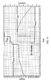
- FIG. 19 is a plot of SOC as a function of t 0 for several XR41 secondary test cells that were charged with a given charge current, I 1 , of 5 mA at temperatures of 20° C., 25° C., 30° C., and 35° C.
- FIG. 20 is a plot of SOC as a function of t 0 for several XR41 secondary test cells that were charged with a given charge current, I 1 , of 5 mA at temperatures of 20° C., 25° C., 30° C., and 35° C.
- FIG. 21A is a step-diagram representing another exemplary method for recharging a rechargeable battery having at least one voltage plateau according to one embodiment of the invention.
- FIG. 21B is a step-diagram representing another exemplary method for recharging a rechargeable battery having at least one voltage plateau according to one embodiment of the invention.
- FIG. 21C is a step-diagram representing another exemplary method for recharging a rechargeable battery having at least one voltage plateau according to one embodiment of the invention.
- FIG. 21D is a step-diagram representing another exemplary method for recharging a rechargeable battery having at least one voltage plateau according to one embodiment of the invention.
- FIG. 21E is a step-diagram representing another exemplary method for recharging a rechargeable battery having at least one voltage plateau according to one embodiment of the invention.
- FIG. 21F is a step-diagram representing another exemplary method for recharging a rechargeable battery having at least one voltage plateau according to one embodiment of the invention.
- FIG. 22 is a plot of a charge curve for a rechargeable battery, wherein the battery is charged according to an exemplary embodiment of the present invention that includes a secondary chemistry detection step.
- polarization peak or “natural polarization peak” refers to a peak voltage value or a sharp spike in battery voltage that precedes a voltage plateau, which is observed when a rechargeable battery having a plurality of voltage plateaus, e.g., at least 2 voltage plateaus, is charged from a voltage of a first plateau to a voltage of a higher plateau with a charge current that is not controlled to clamp the battery's voltage.
- Exemplary voltage plateaus are illustrated in FIG. 2 , as V P , and FIGS. 3A and 3B , as V P1 , V P2 , and V P3 .
- Exemplary polarization peaks are illustrated in FIG. 2 , as V PP , in FIGS.
- the exemplary polarization peaks are observed when the charging current is substantially constant and unclamped. Without limiting the scope of the present invention, it is believed that the polarization peak occurs when the state of flux in the internal chemistry (e.g., the oxidation state of the cathode material, the anode material, or both) of a rechargeable battery is maximized while the battery is being charged with an uncontrolled current. This phenomenon is observed for silver-zinc batteries and others when a voltage plot is generated for a recharging battery when the charge current is substantially constant but not controlled to clamp the battery voltage.
- the internal chemistry e.g., the oxidation state of the cathode material, the anode material, or both
- FIG. 18 An example of this voltage plot is provided in FIG. 18 , wherein the polarization peak is identified in the charge section of the plot. Note that when a rechargeable battery is charged according some methods of the present invention, one or more polarization peaks will not be observed because the one or more charging currents (e.g., the first charge current, the second charge current, or both) is controlled to clamp the battery's voltage.
- the one or more charging currents e.g., the first charge current, the second charge current, or both
- voltage plateau refers to a range of battery capacities wherein the battery's voltage remains substantially unchanged, e.g., having a variance of ⁇ 10% or less or having a variance of ⁇ 5% or less, when the battery is being charged with a substantially constant charge current.
- the voltage range for a voltage plateau is generally narrow, e.g., having a variance of ⁇ 10% or less or having a variance of ⁇ 5% or less
- voltage plateaus are characterized or identified by the lowest voltage on the plateau, e.g., V P . This is exemplified in FIG. 2 , as V P , and in FIGS. 3A and 3B , as V P1 and V P2 .
- voltage plateaus occur when the internal chemistry (e.g., oxidation state of the cathode or anode or both) of a battery's electrochemical cell or cells stabilizes during charging and the modest variance in the battery's voltage along the plateau is governed by kinetic effects rather than nucleation, which is believed to be prominent at voltages between plateaus.
- the voltage plateau phenomenon may be observed when a voltage plot is generated for a recharging battery.
- control means controlling, lowering, or maintaining a charge current so that the voltage of the rechargeable battery being charged is restricted or “clamped”.
- rechargeable battery battery
- battery battery
- electrochemical cell battery
- cell battery having one electrochemical cell.
- depth of discharge and “DOD” are used interchangeably to refer to the measure of how much energy has been withdrawn from a battery or cell, often expressed as a percentage of capacity, e.g., rated capacity. For example, a 100 Ah battery from which 30 Ah has been withdrawn has undergone a 30% depth of discharge (DOD).
- DOD depth of discharge
- state of charge and “SOC” and used interchangeably to refer to the available capacity remaining in a battery, expressed as a percentage of the cell or battery's rated capacity.
- a battery's “initial SOC” refers to the state of charge of the battery before the battery undergoes charging or recharging.
- the terms “silver” or “silver material” refer to any silver compound such as Ag, AgO, Ag 2 O, Ag 2 O 3 , AgOH, AgOOH, AgONa, AgCuO 2 , AgFeO 2 , AgMnO 2 , Ag(OH) 2 , hydrates thereof, or any combination thereof. Note that ‘hydrates’ of silver include hydroxides of silver.
- silver or silver material encompass any of these silver oxides and hydrates (e.g., hydroxides).
- Terms ‘silver’ or ‘silver material’ also includes any of the abovementioned species that are doped and/or coated with dopants and/or coatings that enhance one or more properties of the silver. Exemplary dopants and coatings are provided below.
- silver or silver material includes a silver oxide further comprising a first row transition metal dopant or coating.
- silver includes silver-copper-oxide, silver-iron-oxide, silver-manganese-oxide (e.g., AgMnO 2 ), silver-chromium-oxide, silver-scandium-oxide, silver-cobalt-oxide, silver-titanium-oxide, silver-vanadium-oxide, hydrates thereof, or any combination thereof.
- oxide used herein does not, in each instance, describe the number of oxygen atoms present in the silver or silver material.
- a silver oxide may have a chemical formula of AgO, Ag 2 O 3 , or a combination thereof.
- silver can comprise a bulk material or silver can comprise a powder having any suitable mean particle diameter.
- an “electrolyte” refers to a substance that behaves as an electrically conductive medium.
- the electrolyte facilitates the mobilization of electrons and cations in the cell.
- Electrolytes include mixtures of materials such as aqueous solutions of alkaline agents. Some electrolytes also comprise additives such as buffers.
- an electrolyte comprises a buffer comprising a borate or a phosphate.
- Exemplary electrolytes include, without limitation, aqueous KOH, aqueous NaOH, or the liquid mixture of KOH in a polymer.
- alkaline agent refers to a base or ionic salt of an alkali metal (e.g., an aqueous hydroxide of an alkali metal). Furthermore, an alkaline agent forms hydroxide ions when dissolved in water or other polar solvents.
- alkaline electrolytes include without limitation LiOH, NaOH, KOH, CsOH, RbOH, or combinations thereof. Electrolytes can optionally include other salts to modify the total ionic strength of the electrolyte, for example KF or Ca(OH) 2 .
- Ah refers to Ampere (Amp) Hour and is a scientific unit for the capacity of a battery or electrochemical cell.
- a derivative unit, “mAh” represents a milliamp hour and is 1/1000 of an Ah.
- maximum voltage or “rated voltage” refers to the maximum voltage an electrochemical cell can be charged without interfering with the cell's intended utility.
- the maximum voltage is less than about 2.3 V or less, or about 2.0 V.
- the maximum voltage is less than about 15.0 V (e.g., less than about 13.0 V, or about 12.6 V or less).
- the maximum voltage for a battery can vary depending on the number of charge cycles constituting the battery's useful life, the shelf-life of the battery, the power demands of the battery, the configuration of the electrodes in the battery, and the amount of active materials used in the battery.
- an “anode” is an electrode through which (positive) electric current flows into a polarized electrical device.
- the anode is the negative electrode from which electrons flow during the discharging phase in the battery.
- the anode is also the electrode that undergoes chemical oxidation during the discharging phase.
- the anode is the electrode that undergoes chemical reduction during the cell's charging phase.
- Anodes are formed from electrically conductive or semiconductive materials, e.g., metals, metal oxides, metal alloys, metal composites, semiconductors, or the like. Common anode materials include Si, Sn, Al, Ti, Mg, Fe, Bi, Zn, Sb, Ni, Pb, Li, Zr, Hg, Cd, Cu, LiC 6 , mischmetals, alloys thereof, oxides thereof, or composites thereof.
- Anode materials such as zinc may even be sintered.
- Anodes may have many configurations.
- an anode may be configured from a conductive mesh or grid that is coated with one or more anode materials.
- an anode may be a solid sheet or bar of anode material.
- a “cathode” is an electrode from which (positive) electric current flows out of a polarized electrical device.
- the cathode In a battery or galvanic cell, the cathode is the positive electrode into which electrons flow during the discharging phase in the battery.
- the cathode is also the electrode that undergoes chemical reduction during the discharging phase.
- the cathode is the electrode that undergoes chemical oxidation during the cell's charging phase.
- Cathodes are formed from electrically conductive or semiconductive materials, e.g., metals, metal oxides, metal alloys, metal composites, semiconductors, or the like.
- cathode materials include Ag, AgO, Ag 2 O 3 , Ag 2 O, HgO, Hg 2 O, CuO, CdO, NiOOH, Pb 2 O 4 , PbO 2 , LiFePO 4 , Li 3 V 2 (PO 4 ) 3 , V 6 O 13 , V 2 O 5 , Fe 3 O 4 , Fe 2 O 3 , MnO 2 , LiCoO 2 , LiNiO 2 , LiMn 2 O 4 , or composites thereof.
- Cathode materials such as Ag, AgO, Ag 2 O 3 may even be sintered.
- Cathodes may also have many configurations.
- a cathode may be configured from a conductive mesh that is coated with one or more cathode materials.
- a cathode may be a solid sheet or bar of cathode material.
- a zinc-silver battery comprises an anode comprising zinc and a cathode comprising a silver powder (e.g., Ag 2 O 3 ). Nonetheless, more than one species is present at a battery electrode under most conditions.
- a zinc electrode generally comprises zinc metal and zinc oxide (except when fully charged), and a silver powder electrode usually comprises AgO, Ag 2 O 3 and/or Ag 2 O and silver metal (except when fully discharged).
- oxide applied to alkaline batteries and alkaline battery electrodes encompasses corresponding “hydroxide” species, which are typically present, at least under some conditions.
- resistivity or “impedance” refers to the internal resistance of a cathode in an electrochemical cell. This property is typically expressed in units of Ohms or micro-Ohms.
- first and/or “second” do not refer to order or denote relative positions in space or time, but these terms are used to distinguish between two different elements or components.
- a first separator does not necessarily proceed a second separator in time or space; however, the first separator is not the second separator and vice versa.
- a first separator does not necessarily proceed a second separator in time or space; however, the first separator is not the second separator and vice versa.
- a first separator does not necessarily proceed a second separator in time or space; however, the first separator is not the second separator and vice versa.
- a second separator precedes a first separator in space or time.
- the term “capacity” refers to the mathematical product of a cell's discharge current and the time (in hours) during which the current is discharged until the cell reaches a terminal voltage.
- the terms “actual capacity” or “theoretical capacity” refer to the capacity that a battery or electrochemical cell should theoretically discharge at 100% SOC based on the amounts of electrode materials present in the cell, the amount of electrolyte present in the cell, and the surface area of the electrodes.
- the capacity of a cell/battery is the amount of charge available expressed in ampere-hours (Ah) or milliampere-hours (mAh).
- An ampere is the unit of measurement used for electrical current and is defined as a Coulomb of charge passing through an electrical conductor in one second.
- the capacity of a cell or battery is related to the quantity of active materials present, the amount of electrolyte present, and the surface area of the electrodes.
- the capacity of a battery/cell can be measured by discharging at a constant current until it reaches its terminal voltage, which depends on the cell's intended usage.
- a cell's “rated capacity” is the average capacity delivered by a cell or battery on a specified load and temperature to a voltage cutoff point, as designated by the manufacturer for the cell's intended usage. For many types of cells, industry standards establish a cell's rated capacity, which is based on the cell's intended usage. It is noted that silver-zinc cells typically have a rated capacity that is about 70% or less (e.g., about 50% or less) of the cell's actual capacity.
- a and “Amps” are used interchangeably and refer to a unit of electrical current, e.g., charge current.
- s As used herein, “s”, “sec” and “seconds” are used interchangeably and refer to a unit of time.
- min and “minutes” are used interchangeably and refer to a unit of time, i.e., 60 seconds.
- time As used herein, “hr” and “hour” are used interchangeably and refer to a unit of time, i.e., 60 min.
- one aspect of the present invention provides a method of charging a rechargeable battery having multiple voltage plateaus wherein the battery has a voltage, V Batt , that is less than its highest voltage plateau comprising:
- V 1 Controlling/Modulating the first charging current, I 1 , when the voltage of the battery is V 1 , so that the voltage of the battery is maintained at V 1 with a deviation of no more than about ⁇ 20% (e.g., ⁇ 10%, ⁇ 5%) of V 1 , wherein voltage, V 1 , is less than the voltage of a natural polarization peak, V PP , associated with a voltage plateau, V P , that is higher than V Batt , and V 1 is greater than the voltage plateau, V P .
- Several methods optionally comprise terminating the charging current, I 2 , when I 2 is controlled to be about 95% or less of the charge current during the period when the battery was being charged to V 2 .
- charge current I 1 is substantially constant during the period wherein V Batt is less than or equal to V 1 .
- charge current I 2 is substantially constant during the period wherein V Batt is less than or equal to V 2 .
- charge current I 1 is greater than or equal to charge current I 2 before the battery is charged to V 1 .
- I 1 is greater than charge current I 2 before the battery is charged to V 1 .
- I 1 is equal to charge current I 2 before the battery is charged to V 1 .
- the second charging current, I 2 is applied at least until the battery is charged to a SOC of from about 80% to about 150% (e.g., from about 80% to about 110%) of the battery's rated capacity.
- the first charging current, I 1 is sufficient to charge the battery to voltage, V 1 , in a period of from about 1 min to about 300 min (e.g., from about 5 min to about 300 min, from about 5 min to about 240 min, or from about 10 min to about 90 min) when the battery's initial SOC is less than 40% (e.g., less than 30%) of its rated capacity.
- the first charging current, I 1 is sufficient to charge the battery to a voltage of V 1 in a period of from about 10 min to about 260 min (e.g., about 10 min to about 180 min), when the battery's initial SOC is less than 40% (e.g., less than 30%) of its rated capacity.
- the first charging current, I 1 is sufficient to charge the battery to voltage, V 1 , in a period of about 75 min or less (e.g., from about 5 min to about 75 min or from about 15 min to about 75 min) when the battery's initial SOC is less than 40% (e.g., less than 30%) of its rated capacity.
- the first charging current, I 1 is sufficient to charge the battery from a SOC of less than 30% (e.g., less than 20%) of its rated capacity to a SOC of from about 30% to about 40% of its rated capacity in about 240 min or less (e.g., about 180 min or less).
- the first charging current, I 1 is sufficient to charge the battery from a SOC of less than 30% (e.g., less than 20%) of its rated capacity to a SOC of about 40% its rated capacity in less than about 240 min (e.g., less than about 180 min).
- the first charging current, I 1 is controlled when the voltage of the battery is V 1 , so that the voltage of the battery is maintained at V 1 with a deviation of no more than about ⁇ 20% of V 1 , for a period of from about 1 s to about 1500 s (e.g., from about 6 s to about 1500 s, from about 6 s to about 1200 s, or from about 6 s to about 900 s).
- some methods include controlling the first charging current, I 1 , when the voltage of the battery reaches a voltage, V 1 , so that the voltage of the battery is maintained at V 1 with a deviation of no more than about ⁇ 10% of V 1 for a period of from about 6 s to about 1200 s (e.g., from about 6 s to about 900 s).
- Other examples include controlling the first charging current, I 1 , when the voltage of the battery reaches V 1 , so that the voltage of the battery is maintained at V 1 with a deviation of no more than about ⁇ 10% of V 1 for a period of from about 6 s to about 600 s.
- Some methods further comprise:
- V 1 is greater than or equal to V 2 .
- V 1 is greater than V 2 .
- V 1 is equal to V 2 .
- V Batt is from about 50% to about 87% of the voltage, V 1 .
- I 1 is about 500 Amps or less.
- I 1 is from about 100 mA to about 500 Amps.
- I 2 is about 500 Amps or less.
- I 2 is from about 100 mA to about 500 Amps.
- the battery has a rated capacity of from about 1 Ah to about 1000 Ah.
- I 1 is about 500 mA or less.
- I 1 is from about 20 mA to about 500 mA.
- I 2 is about 500 mA or less.
- I 2 is from about 20 mA to about 500 mA.
- the battery has a rated capacity of from about 200 mAh to about 1 Ah.
- I 1 is about 50 mA or less.
- I 1 is from about 5 mA to about 50 mA.
- I 2 is about 50 mA or less.
- I 2 is from about 5 mA to about 50 mA.
- the battery has a rated capacity of from about 50 mAh to about 200 mAh.
- I 1 is about 25 mA or less.
- I 1 is from about 400 ⁇ A to about 25 mA.
- I 2 is about 25 mA or less.
- I 2 is from about 400 ⁇ A to about 25 mA.
- the battery has a rated capacity of from about 4 mAh to about 50 mAh.
- I 1 is about 2 mA or less.
- I 1 is from about 10 ⁇ A to about 2 mA.
- I 2 is about 2 mA or less.
- I 2 is from about 10 ⁇ A to about 2 mA.
- the battery has a rated capacity of from about 1 mAh to about 4 mAh.
- I 1 is about 50 mA or less.
- I 1 is from about 500 mA to greater than 8 mA.
- I 1 is from about 5 mA to about 500 mA.
- I 2 is less than 500 mA.
- I 2 is from less than about 500 mA to about 1 mA.
- the battery has a rated capacity of from about 1 Ah to about 4 Ah.
- I 1 is about 1 Amp or less.
- I 1 is from about 1 Amps to greater than 10 mA.
- I 1 is from about 10 mA to about 1 A (e.g., from about 10 mA to about 0.99 A).
- I 2 is less than 1 Amp.
- I 2 is less than 1 Amp to about 10 mA.
- I 2 is from about 10 mA to about 0.99 A.
- the battery has a rated capacity of from about 100 mAh to about 1000 mAh.
- I 1 is about 100 mA or less.
- I 1 is from about 100 mA to about greater than 1.0 mA.
- I 1 is from about 1.0 mA to about 99.99 mA.
- I 2 is less than 100 mA (e.g., less than 75 mA).
- I 2 is from less than 75 mA to about 5 mA.
- I 2 is from about 5 mA to about 99.99 mA.
- the battery has a rated capacity of from about 15 mAh to about 150 mAh (e.g., from about 50 mAh to about 100 mAh).
- I 1 is about 150 mA or less.
- I 1 is from about 0.3 mA to about 60 mA.
- I 2 is less than about 150 mA.
- I 2 is from about 0.2 mA to about 149.99 mA.
- the battery has a rated capacity of from about 4 mAh to about 150 mAh.
- I 1 is about 25 mA or less.
- I 1 is from about 25 mA to greater than 0.4 mA.
- I 2 is less than 25 mA.
- I 2 is from less than 25 mA to about 0.2 mA.
- the battery has a rated capacity of from about 4 mAh to about 50 mAh.
- I 1 is about 15 mA or less.
- I 1 is from about 15 mA to greater than 0.1 mA.
- I 2 is less than 15 mA.
- I 2 is from less than 15 mA to about 0.1 mA.
- the battery has a rated capacity of from about 1.0 mAh to about 15 mAh.
- I 1 is from about 3.0 mA to about 3.5 mA.
- the battery has a theoretical capacity of from about 40 mAh to about 50 mAh (e.g., about 44 mAh). In others, the battery has a rated capacity of from about 15 mAh to about 20 mAh (e.g., about 18 mAh). And, in some embodiments, the battery stores from about 25 mWh to about 30 mWh (e.g., about 29 mWh).
- I 1 is from about 4.7 mA to about 5.6 mA.
- the battery has a theoretical capacity of from about 50 mAh to about 60 mAh (e.g., about 57 mAh). In others, the battery has a rated capacity of from about 20 mAh to about 30 mAh (e.g., about 28 mAh). And, in some embodiments, the battery stores from about 40 mWh to about 50 mWh (e.g., about 45 mWh).
- I 1 is from about 5.4 mA to about 6.4 mA.
- the battery has a theoretical capacity of from about 60 mAh to about 80 mAh (e.g., about 70 mA to about 80 mA or about 78 mAh). In others, the battery has a rated capacity of from about 30 mAh to about 40 mAh (e.g., about 32 mAh). And, in some embodiments, the battery stores from about 50 mWh to about 60 mWh (e.g., about 51 mWh).
- I 1 is from about 15 mA to about 24 mA.
- the battery has a theoretical capacity of from about 250 mAh to about 275 mAh (e.g., about 269 mAh).
- the battery has a rated capacity of from about 100 mAh to about 140 mAh (e.g., about 120 mAh).
- the battery stores from about 175 mWh to about 225 mWh (e.g., about 192 mWh).
- the voltage, V 2 is from about 85% to about 100% (e.g., from about 90% to about 100% or from about 90% to about 99%) of V 1 .
- the voltage, V 2 is from about 96% to about 99.5% of V 1 .
- V 1 is about 2.04 V or less.
- V 1 is from about 1.96 V to about 2.04 V. In other examples, V 1 is from about 1.96 V to about 1.99 V.
- V 2 is about 2.03 V or less.
- V 2 is from about 1.93 V to about 2.03 V. In other examples, V 2 is from about 1.93 V to about 1.98 V.
- Another aspect of the present invention provides a method of charging a rechargeable battery having multiple voltage plateaus, wherein the battery has a voltage, V Batt , that is less than its highest voltage plateau comprising: charging the battery with a first charging current, I 1 , wherein the first charging current, I 1 , is substantially constant until the battery is charged to a voltage, V 1 ; and controlling the first charging current, I 1 , when the voltage of the battery is V 1 , so that the voltage of the battery is maintained at V 1 with a deviation of no more than about ⁇ 20% of V 1 for a period of from about 6 s to about 1200 s (e.g., from about 6 s to about 900 s), wherein voltage, V 1 , is less than the voltage of the natural polarization peak, V PP , for a voltage plateau, V P , that is higher than V Batt , and V 1 is greater than the voltage plateau, V P .
- Some methods further comprise charging the battery with a second charging current, I 2 , that is less than or equal to the first charging current, I 1 , when the battery has a voltage of less than V 1 , wherein the second charging current, I 2 , is substantially constant until the battery voltage reaches a voltage, V 2 , wherein the voltage, V 2 , is less than or equal to the voltage, V 1 , and greater than V Batt , and controlling the second charging current, I 2 , when the voltage of the battery reaches the voltage, V 2 , so that the voltage of the battery is maintained at V 2 with a deviation of no more than about ⁇ 20% of V 2 .
- some methods also comprise terminating the second charging current, I 2 , after a period of about 10 min or less (e.g., about 5 min or less) from the point when the battery is charged to a SOC of from about 80% to about 150% (e.g., from about 80% to about 110%) of the battery's rated capacity.
- the first charging current, I 1 is sufficient to charge the battery to voltage, V 1 , in a period of from about 5 min to about 240 min when the battery's initial SOC is less than 40% (e.g., less than 30%) of its rated capacity. In other methods, the first charging current, I 1 , is sufficient to charge the battery to a voltage of V 1 in a period of from about 10 min to about 180 min, when the battery's initial SOC is less than 40% (e.g., less than 30%) of its rated capacity.
- the first charging current, I 1 is sufficient to charge the battery to a voltage of V 1 in a period of from about 15 min to about 75 min, when the battery's initial SOC is less than 40% (e.g., less than 30%) of its rated capacity.
- the first charging current, I 1 is sufficient to charge the battery from a SOC of less than 30% (e.g., less than 20%) of its rated capacity to a SOC of from about 30% to about 40% of its rated capacity in about 240 min or less (e.g., about 180 min or less).
- the first charging current, I 1 is sufficient to charge the battery from a SOC of less than 40% (e.g., less than 30%) of its rated capacity to a SOC of about 40% its rated capacity in less than about 240 min.
- the first charging current, I 1 is sufficient to charge the battery to a voltage of V 1 in a period of about 75 min or less, when the battery's initial SOC is less than 40% (e.g., less than 30%) of its rated capacity.
- V Batt is from about 50% to about 87% of the voltage, V 1 .
- Other methods further comprise controlling the first charging current, I 1 , when the voltage of the battery reaches a voltage, V 1 , so that the voltage of the battery is maintained at V 1 with a deviation of no more than about ⁇ 10% of V 1 for a period of from about 6 s to about 1200 s (e.g., from about 6 s to about 900 s or from about 550 s to about 650 s).
- some of these methods further comprise generating an electrical signal that indicates a soft short in the battery if V Batt is lower than V P (e.g. 1.90 V) for a period of more than 1 second after the battery has been charged to a voltage of V 2 .
- V P e.g. 1.90 V
- some of these methods further comprise charging the battery with a diagnostic charge current, I Diag , to determine whether the battery is compatible with some steps of the present charging method.
- One embodiment comprises charging the battery with a diagnostic charge current, I Diag , for a period of less than about 30 s, detecting the voltage of the battery, V Batt , and terminating charging of the battery if V Batt is about 1.65 V or less (e.g., less than about 1.65 V).
- I Diag is greater than or equal to I 1 .
- I Diag is from about 5% to about 200% greater than I 1 .
- I Diag is from about 30% to about 100% greater than I 1 .
- I Diag is about equal to I 1 .
- Other embodiments comprise charging the battery with a diagnostic charge current, I Diag that is about 10% to about 200% higher than I 1 for a period of less than about 10 s, detecting the voltage of the battery, V Batt , and terminating charging of the battery if V Batt is about 1.60 V or less.
- Some methods comprise charging the battery with a diagnostic charge current, I Diag that is about 30% to about 100% higher than I 1 for a period of less than about 5 s, detecting the voltage of the battery, V Batt , and terminating charging of the battery if V Batt is about 1.55 V or less.
- the voltage, V 2 is from about 90% to about 100% of V 1 .
- the voltage, V 2 is from about 96% to about 99.5% of V 1 .
- V 1 is about 2.04 V or less.
- V 1 is from about 2.04 V to about 1.96 V.
- V 1 is from about 1.99 V to about 1.96 V.
- V 2 is about 2.03 V or less.
- V 2 is from about 2.03 V to about 1.93 V.
- V 2 is from about 1.93 V to about 1.98 V.
- One aspect of the present invention provides a method of detecting a rechargeable silver-zinc battery comprising charging the battery with a diagnostic charge current, I Diag , for a period of less than about 60 s, detecting the voltage of the battery, V Batt , and terminating charging of the battery if V Batt is about 1.60 V or less (e.g., about 1.55 V or less); wherein I Diag is about 25 mA or less.
- the battery is charged with I Diag for a period of about 7 s or less, detecting the voltage of the battery, V Batt , and generating an electrical signal if V Batt is about 1.60 V or less, wherein I Diag is from about 20 mA to about 25 mA or about 10 mA or less.
- the electrical signal activates an audio alarm, a visual alarm, a vibrational alarm, or any combination thereof.
- another aspect of the present invention provides a method of charging a rechargeable battery having multiple voltage plateaus wherein the battery has a voltage, V Batt , that is less than about 80% (e.g., less than about 70%) of the voltage of a first sequential voltage plateau, V P1 , comprising:
- I recov a recovery charging current, that is substantially constant for a period of no more than about 120 min (e.g., no more than 30 min, no more than about 20 min, or no more than about 15 min) after the voltage of charging battery reaches the first sequential voltage plateau, V P1 that is greater than V Batt ;
- V 1 is less than the voltage of the natural polarization peak, V PP , for a voltage plateau, V P , that is higher than V P1 , and V 1 is greater than the voltage plateau, V P .
- I recov is from about 5% to about 90% of I 1 .
- I recov is from about 10% to about 30% of I 1 .
- Some methods further comprise:
- Some methods further comprise generating an electrical signal that indicates that the battery is experiencing a short (e.g., a soft short or a hard short) if the voltage of the battery, V Batt , fails to reach the first sequential voltage plateau, V P1 , that is greater than V Batt after being charged with I recov for a period of from about 15 minutes to 2 hours (e.g., from about 30 min to about 120 min).
- a short e.g., a soft short or a hard short
- Some methods of this aspect also exclude counting Coulombs to assess the capacity that is charged to a battery.
- the rechargeable battery comprises an anode comprising a zinc material.
- the rechargeable battery comprises a cathode comprising a silver material.
- Exemplary batteries that may be recharged using methods of the present invention include button cells, coin cells, cylinder cells, or prismatic cells.
- the methods above may optionally include additional steps such as generating an electrical signal when the second charging current, I 2 , terminates. Some methods further include activating a visual signal, activating an audio signal, activating a vibrational signal, or any combination thereof when the second charging current, I 2 , terminates.
- another aspect of the present invention provides a method of charging a rechargeable button cell having multiple voltage plateaus wherein the cell has a voltage greater than about 1.10 V and less than about 1.70 V (e.g., greater than 1.20 V and 1.70 V) comprising:
- Some methods further comprise:
- the first charging current, I 1 is sufficient to charge the battery to the voltage, V 1 , in a period of from about 1 min to about 180 min (e.g., from about 30 min to about 180 min).
- Other methods further comprise controlling the first charging current, I 1 , when the voltage of the cell reaches the voltage, V 1 , so that the voltage of the battery is maintained at V 1 with a deviation of no more than about ⁇ 10% of V 1 for a period of from about 550 s to about 650 s.
- the voltage, V 2 is from about 90% to about 100% of V 1 .
- the voltage, V 2 is from about 96% to about 99.5% of V 1 .
- I 1 is about 1 Amp or less.
- I 1 is from about 1 Amps to greater than 80 mA.
- I 1 is from about 80 mA to about 1 A (e.g., from about 8 mA to about 0.99 A).
- I 2 is less than 1 Amp.
- I 2 is less than 1 Amp to about 80 mA.
- I 2 is from about 80 mA to about 0.99 A.
- the battery has a rated capacity of from about 100 mAh to about 1000 mAh.
- I 1 is about 300 mA or less.
- I 1 is from about 250 mA to about greater than 8 mA.
- I 1 is from about 8 mA to about 299.99 mA.
- I 2 is less than 300 mA (e.g., less than 250 mA).
- I 2 is from less than 250 mA to about 4 mA.
- I 2 is from about 4 mA to about 299.99 mA.
- the battery has a rated capacity of from about 15 mAh to about 150 mAh (e.g., from about 50 mAh to about 100 mAh).
- the voltage, V 2 is from about 1.93 V to about 1.98 V.
- I 1 is about 25 mA or less.
- I 1 is from about 25 mA to greater than 4 mA.
- I 2 is less than 25 mA.
- I 2 is from less than 25 mA to about 2 mA.
- the battery has a rated capacity of from about 4 mAh to about 50 mAh.
- I 1 is about 15 mA or less.
- I 1 is from about 15 mA to greater than 0.1 mA.
- I 2 is less than 15 mA.
- I 2 is from less than 15 mA to about 0.1 mA.
- I 1 is from about 3.0 mA to about 3.5 mA.
- the battery has a theoretical capacity of from about 40 mAh to about 50 mAh (e.g., about 44 mAh). In others, the battery has a rated capacity of from about 15 mAh to about 20 mAh (e.g., about 18 mAh). And, in some embodiments, the battery stores from about 25 mWh to about 30 mWh (e.g., about 29 mWh).
- I 1 is from about 4.7 mA to about 5.6 mA.
- the battery has a theoretical capacity of from about 50 mAh to about 60 mAh (e.g., about 57 mAh). In others, the battery has a rated capacity of from about 20 mAh to about 30 mAh (e.g., about 28 mAh). And, in some embodiments, the battery stores from about 40 mWh to about 50 mWh (e.g., about 45 mWh).
- I 1 is from about 5.4 mA to about 6.4 mA.
- the battery has a theoretical capacity of from about 70 mAh to about 80 mAh (e.g., about 78 mAh).
- the battery has a rated capacity of from about 30 mAh to about 40 mAh (e.g., about 32 mAh).
- the battery stores from about 50 mWh to about 60 mWh (e.g., about 51 mWh).
- I 1 is from about 15 mA to about 24 mA.
- the battery has a theoretical capacity of from about 250 mAh to about 275 mAh (e.g., about 269 mAh).
- the battery has a rated capacity of from about 100 mAh to about 140 mAh (e.g., about 120 mAh).
- the battery stores from about 175 mWh to about 225 mWh (e.g., about 192 mWh).
- the voltage, V 2 is from about 90% to about 100% of V 1 .
- the voltage, V 2 is from about 96% to about 99.5% of V 1 .
- the voltage, V 1 is from about 1.95 V to about 1.99 V.
- the first charging current, I 1 is modulated for a period of about 550 s to about 650 s.
- the voltage, V 2 is from about 1.93 V to about 1.98 V.
- the battery comprises an anode comprising a zinc material.
- the battery comprises a cathode comprising a silver material.
- Some methods further comprise generating an electrical signal when the second charging current, I 2 , is terminated. And, other methods further comprise activating a signal or alert (e.g., a visual signal, an audio signal, a vibrational signal, or any combination thereof) when the second charging current, I 2 , is terminated.
- a signal or alert e.g., a visual signal, an audio signal, a vibrational signal, or any combination thereof
- the present invention provides a method of charging a rechargeable battery having multiple voltage plateaus and an initial SOC of greater than 50% of its rated capacity, wherein the battery has a voltage, V Batt , that is less than or equal to its highest voltage plateau comprising:
- V 2 is greater than or equal the voltage of a voltage plateau, V P , that is less than the voltage of a natural polarization peak, V PP .
- Some methods further comprise:
- V 2 is about 2.0 V or less.
- I 2 is about 6 mA. In other methods, I ter is about 4.5 mA.
- FIGS. 8A-8D Examples of additional methods of the present invention are presented in the FIGS. 8A-8D .
- One method includes the following steps:
- Step 1 Measuring the SOC of the cell.
- Step 2A If the SOC of the cell is greater than about 0.0% and less than or equal to about 40% (e.g., the open circuit voltage (OCV) is greater than about 1.2 V and less than or equal to about 1.7 V), then charging the cell according to a multi-stage charge process (starting at step 3A, below).
- OCV open circuit voltage
- Step 2B If the SOC is greater than about 50% (e.g., the OCV is greater than about 1.7 V (e.g., about 1.85 V or greater)), then charging the cell according to a single stage charge process (starting at step 3B, below).
- the SOC is greater than about 50% (e.g., the OCV is greater than about 1.7 V (e.g., about 1.85 V or greater)
- Step 2C If the SOC is less than 30% (e.g., the OCV is about 1.2 V or less), then charging the cell according to an over-discharge recovery process (starting at step 3C, below).
- 30% e.g., the OCV is about 1.2 V or less
- Step 3A (Zone 1 of Multi-zone Charge Process): Charging the cell with a substantially constant charge current, I 1 , having sufficient amperage to charge the cell to a SOC of from about less than 30% to about 40% of its rated capacity within about 1 hour of charging, wherein the charge current, I 1 , is controlled such that the cell is charged to a voltage, V 1 , that is less than its natural polarization peak voltage, V PP , for a period of time ending from about 6 s to about 1500 s (e.g., from about 6 s to about 1200 s, from about 6 s to about 900 s, or from about 6 s to about 600 s) after the cell is charged to a voltage of V 1 , then charging the cell according to stage 2 of the multi-zone charge process.
- V 1 voltage
- V PP natural polarization peak voltage
- Step 4A (Zone 2 of Multi-zone Charge Process): Charging the cell with a substantially constant charge current, I 2 , wherein the charge current is controlled such that the voltage of the cell does not rise above a maximum voltage, V 2 that is less than its natural polarization peak voltage, V PP ; and greater than the voltage of the voltage plateau; clocking the time that the cell is charged with a charge current of I 2 , and terminating the charge current about 60 s after the battery is charged to an SOC of 85% or higher (e.g., from about 85% to about 150% or from about 85% to about 130%) of its rated capacity.
- Step 3B Charging the cell with a charge current, I 2 , wherein the charge current is controlled such that the voltage of the cell does not rise above a maximum voltage, V 2 that is less than its natural polarization peak voltage, V PP ; and greater than the voltage of the voltage plateau; clocking the time that the cell is charged with a charge current of I 2 to a voltage of V 2 , and terminating the charge current about 60 s after the cell is charged to an SOC of 85% or higher (e.g., from about 80% to about 150% or from about 80% to about 110%) of its rated capacity.
- Step 3C Charging the cell with a constant charge current, I recov , until the cell is charged to a voltage, V P1 , of the first sequential voltage plateau (e.g., an SOC of about less than about 30% or an SOC of less than about 5% of the cell's rated capacity), followed by charging the cell according to the multi-stage charge method described above.
- a constant charge current, I recov e.g., an SOC of about less than about 30% or an SOC of less than about 5% of the cell's rated capacity
- FIGS. 2, 4, 5, 6, and 8A-8D Each of the abovementioned charging methods (e.g., the multi-stage charge process, the single-stage charge process, or the over-discharge recovery charge process) is exemplified in FIGS. 2, 4, 5, 6, and 8A-8D .
- the charge curve includes two corresponding curves, which are plotted against time and read left-to-right.
- the first curve starting at about 1.65 V, is the voltage of the silver-zinc cell after charging has commenced, and, in an embodiment, the second curve, starting at about 8.5 mA is the charge current of the silver-zinc cell.
- recharging management circuitry such as the circuitry illustrated in FIG. 1 , useful for practicing the method of the present invention may be located within a charging base, which may be described as a current-limited voltage source.
- the management circuitry may be split between the charging base, the battery, an electronic device powered by the battery, or any combination thereof.
- the recharging management circuitry may include the hardware for implementing the charge method and cause the charging base to deliver the first charge current, I 1 , when the SOC of the silver-zinc cell is less than about 40%, wherein the first charge current, I 1 , is controlled so that the voltage of the battery does not exceed V 1 .
- the recharging management circuitry may cause the charging base to deliver a second charge current, I 2 , wherein the second charge current is controlled so that the cell is not charged above a second maximum voltage level, V 2 , wherein V 2 is less than or equal to V 1 .
- the charging method for charging of the silver-zinc cell may be terminated when the controlled charge current, I 2 , is less than or equal to a minimum charge current, I ter , for a period of about 60 s (e.g., from about 30 s to about 90 s, or from about 50 s to about 70 s).
- the charge voltage accuracy may be within about ⁇ 2 mV between 1.900-2.000 V. In an embodiment, the voltage accuracy may be within about ⁇ 25 mV between 1.900-1.200 V. Further, in an embodiment, the charge current accuracy may be within about ⁇ 0.1 mA. Further, in an embodiment, the temperature measurement accuracy may be within about ⁇ 5° C. (e.g., ⁇ 2° C.) and be a measure of the ambient temperature; further, in an embodiment, the temperature measurement does not have to measure the cell case temperature.
- the following limits may also be considered in the design of one or more of the silver-zinc cell, system, and charge methods.
- the voltage of the silver-zinc cell may not exceed 2.00 V for more than one (1) second continuously.
- any voltage excursion above the 2.00 V limit may result from a charge voltage/current transition while the charging base is stabilizing the charge voltage on the silver-zinc cell.
- the charge current, I 2 or I ter may not fall below a “trickle” charge level of about 1 mA for more than thirty (30) minutes continuously.
- the maximum charge time (at about room temperature) of a silver-zinc cell may be about six (6) hours.
- a silver-zinc cell may be charged when ambient temperature conditions are between about approximately about 0° C. and about approximately about 40° C. Further, in an embodiment, the cell current may be integrated during charging and may not exceed 27 mAh in a single charge.
- a discharge warning signal triggers a Coulomb count terminated cycle.
- FIGS. 10-17 another aspect of the present invention provides a method of charging a rechargeable battery having multiple voltage plateaus comprising:
- I max is the maximum current charged to the battery
- T Chg is the cell time constant
- the voltages have a deviation of ⁇ 0.5%
- the current amperages have deviations of ⁇ 2%
- clocked times have a deviation of ⁇ 2%. This calculation is discussed in detail below.
- I end is I 1end . In others, I end is I 2end .
- the charge current is arrested when the charge current, I 1 , has an amperage less than or equal to I end for a continuous period of from about 30 s to about 90 s (e.g., 60 s).
- the charge current is arrested when the cell experiences a hard short.
- the charge current is arrested when the cell is determined to be other than a silver zinc cell.
- V max is 2.03 V or 2.0 V.
- the charge current has a maximum amperage, I max , of about 10 mA or less (e.g., about 6 mA or less).
- the charge current has a maximum amperage, I max , of 5.5 mA or less.
- some methods include measuring the temperature, wherein the temperature measurement accuracy has a deviation of ⁇ 5° C.
- Another aspect of the present invention provides a method of charging a rechargeable battery having multiple voltage plateaus comprising:
- Some embodiments further comprise arresting charge current I 2 when the amperage of I 2 is below I 2end for a period of from about 30 to about 90 (e.g., about 60) continuous seconds.
- Some embodiments further comprise arresting charge current I 2 once the battery is charged to an SOC of about 50%, if the lowest amperage of I 2 , I 2low , is less than the amperage of charge current I 2 after 20 minutes has been clocked, wherein the SOC of the battery is determined by integrating the charge current while time is being clocked.
- Some embodiments further comprise arresting charge current I 1 when the amperage of I 1 is below I 1min , e.g., 1.0 V, for a period of about 5 min or less.
- I 1min e.g., 1.0 V
- the voltages have a deviation of ⁇ 0.5%; the charge current amperages have deviations of ⁇ 2%; and clocked time has a deviation of ⁇ 2%.
- Another aspect of the present invention provides a method of charging a 2.0 V rechargeable battery comprising:
- I 2 Arresting charge current I 2 when the amperage of I 2 is below I 2end for a period of 60 continuous seconds if the amperage of I 2 is I max for a period of 5 or more continuous seconds when time is being clocked, wherein I 2end is the temperature dependent minimum charge current necessary to maintain a voltage of 2.0 V in the battery when the battery is charged to an SOC of about 100% of its rated capacity; or
- Some methods further comprise charging the battery with a second modulated charge current I 2 , wherein the second charge current I 2 is modulated so that the voltage of the battery is restricted to 2.0 V or less, and the charge current amperage is restricted to a maximum amperage, I max , of 5.0 mA; clocking time when the voltage of the battery is 1.9 V; and continuously charging the battery with charge current I 2 until 20 minutes has been clocked.
- the battery being charged is a size 10, 13, 312, or 675 rechargeable silver-zinc button cell.
- Another aspect of the present invention provides a method of charging a rechargeable 2.0 V silver-zinc battery comprising charging the battery with a charge current, I 2 , having a maximum amperage, I max , of about 10 mA or less (e.g., about 6 mA or less) wherein the charge current I 2 is modulated so that the voltage of the battery is restricted to about 2.03 V or less; clocking time 60 seconds after charging with second charge current, I 2 , begins; measuring the lowest amperage, I low , of charge current I 2 when time is being clocked; and arresting charge current I 2 once the battery is charged with from about 40% to about 60% (e.g., about 50%) of its rated capacity with charge current, I 2 , wherein the capacity charged to the battery is determined by integrating the charge current, I 2 , while time is being clocked; and the voltages have a deviation of ⁇ 0.5%, the current amperages have deviations of ⁇ 2%, and clocked times have a deviation of ⁇ 2%.
- the battery has an OCV of greater than about 1.6 V (e.g., greater than about 1.65 V or greater than about 1.7 V) in its discharged state, i.e., immediately before charging.
- Another aspect of the present invention provides a method of charging a rechargeable 2.0 V silver-zinc battery comprising charging the battery with a charge current, I 2 , having a maximum amperage, I max , of about 10 mA or less (e.g., about 6 mA or less) wherein the charge current I 2 is modulated so that the voltage of the battery is restricted to about 2.03 V or less; clocking time 60 seconds after charging with second charge current, I 2 , begins; measuring the lowest amperage, I low , of charge current I 2 when time is being clocked; and arresting charge current I 2 when the amperage of I 2 is below I end for a period of 60 continuous seconds if the amperage of I 2 is I max for a period of 2 continuous seconds while time is being clocked; or arresting charge current I 2 once the battery is charged with from about 40% to about 60% (e.g., about 50%) of its rated capacity with charge current I 2 , if I low is less than the amperage of charge current I 2 after 20
- the battery has an OCV of greater than about 1.6 V (e.g., greater than about 1.65 V or greater than about 1.7 V) in its discharged state.
- Some embodiments further comprise measuring the temperature, wherein the temperature measurement has accuracy of about ⁇ 5° C. (e.g., ⁇ 2° C.).
- Another aspect of the present invention provides a method of charging a rechargeable 2.0 V silver-zinc battery comprising charging the battery with first charge current, I 1 , having a maximum amperage, I max , of about 10 mA or less (e.g., about 6 mA or less); clocking time once the battery is charged to a voltage of 1.90 V; modulating the first charge current, I 1 , so that the voltage of the battery is restricted to about 2.03 V or less; arresting the first charge current, I 1 , once from between about 10 min to about 30 min (e.g., about 20 min) has been clocked; charging the battery with second charge current, I 2 , having a maximum amperage, I max , of about 10 mA or less (e.g., about 6 mA or less) wherein the second charge current I 2 is modulated so that the voltage of the battery is restricted to about 2.0 V or less; clocking time 60 seconds after charging with second charge current, I 2 , begins; measuring the lowest amperage, I low
- Some of these methods further comprise measuring the temperature, wherein the temperature measurement has an accuracy of about ⁇ 5° C. (e.g., ⁇ 2° C.).
- the maximum amperage, I max is about 6 mA or less.
- I max is about 5.5 mA or less.
- the battery has an OCV of less than about 1.70 V (e.g., about 1.65 V or less) in its discharged state.
- the OCV of the battery is greater than 1.25 V prior to charging.
- the OCV of the battery is less than 1.25 V prior to charging.
- Some embodiments further comprise charging the battery with a recovery charge current of 1.0 mA for a period of at least 20 minutes (e.g., at least 30 minutes); and arresting the recovery charge current when the battery is charged to a voltage of about 1.50 V or more (e.g., about 1.6 V).
- FIGS. 8A-9 Other exemplary methods are provided, as a step-diagrams, in FIGS. 8A-9 .
- the battery charger is a current limited voltage source.
- the charger delivers maximum allowed current as set by the charge method.
- cell voltage rises to the maximum allowed voltage, and the charge current is modulated, i.e., reduced, to maintain the battery's voltage at the maximum allowed voltage.
- the charge voltage accuracy has a deviation of ⁇ 0.5% (e.g., ⁇ 10 mV between 1.200-2.000 V).
- the charge current accuracy has a deviation of ⁇ 2% (e.g., ⁇ 0.1 mA between 1-5 mA).
- time is measured or clocked with an accuracy of ⁇ 2% (e.g., for a 5 hour time period, the accuracy is ⁇ 0.1 hours).
- the temperature measurement accuracy has a deviation of ⁇ 5° C. (e.g., ⁇ 2° C.). The temperature measurement does not have to measure the cell case temperature, only the ambient temperature.
- the cell voltage does not exceed 2.00 V for more than 1 second continuously. Voltage excursions above this voltage limit should be due to a charge voltage/current transition while the charger is stabilizing the charge voltage on the cell.
- V max the maximum charge voltage for the cell is labeled as V max . Voltage ripple is allowed in these charge methods, but the peak should not exceed 2.0V.
- V max is 1.98 V.
- the cell charge current does not fall below a minimum level, I min for more than 5 minutes continuously.
- the maximum charge current for the cell is I max .
- Current ripple is allowed but the voltage peak should not exceed 2.0 V.
- I min is 1.0 mA.
- I max is 5.0 mA (e.g., I max is 5.0 mA when the rated capacity of the battery is 31 mAh).
- I max is 5.5 mA (e.g., I max is 5.5 mA when the rated capacity of the battery is 35 mAh).
- Another aspect of the present invention provides a method of charging a rechargeable 2.0 V silver-zinc battery having an voltage (e.g., OCV) of less than 1.7 V comprising:
- zone 1 includes the steps of the charge method starting from the initial steps through the steps charging the battery to a voltage, V max , that is less than the natural polarization peak.
- Zone 2 includes the steps of the charge method starting from about 30 s to about 90 s after the battery is charged to V max (e.g., at the end of T 1 in FIG. 11 ) and continues until the charge current is terminated. Charging is terminated when the charge current drops to a termination current level in Zone 2. The termination current level depends on which zone the cell started charging.
- the battery voltage e.g., OCV
- the cell is deeply discharged, typically to a SOC of less than 50% of its rated capacity. If allowed to settle, the battery's open circuit voltage (OCV) will settle at 1.60 V.
- I max e.g., 5.0 mA or 5.5 mA
- V max e.g., 1.98 V or 2.0 V.
- T 1 a Polarization Peak timer
- the Polarization Peak timer clocks about 20 minutes of time (e.g., from 60-240 minutes).
- Zone 2 is entered when T 1 timer is complete, i.e., the timer has clocked 20 minutes.
- the charge set points are maintained at V max (e.g., 1.98 V or 2.0 V) and I max (e.g., 5.0 mA or 5.5 mA).
- V max e.g., 1.98 V or 2.0 V
- I max e.g., 5.0 mA or 5.5 mA.
- the charge current continues until the charge current is less than I end for 60 seconds continuously.
- I end is the calculated charge termination current in mA, which compensates for state of charge, cell aging, and ambient temperature.
- I end I Chg +I Temp (1)
- I Chg is the charge compensation current, in mA
- I Temp is the temperature compensation current in mA that are provided in Tables 1A and 1B:
- I Chg is a calculated value based on a constant current timer, T 2 , the measured length of time the cell is charged under constant current in Zone 2, e.g., when I 2 is substantially constant.
- T 1 When timer T 1 starts, timer T 2 also starts. Timer T 2 ends when charge current falls below I max after T 1 ends. The minimum value for T 2 is T 1 .
- a battery that is in its early stages of cycle life will have a lower impedance and will accept charge more easily, which results in a longer measured T 2 .
- a longer T 2 results in a larger I Chg which terminates charge sooner while the charge current is higher.
- a battery that is in its later stages of life will have a higher impedance and more difficulty in accepting charge, which results in a shorter T 2 .
- a shorter T 2 results in a smaller I Chg which terminates charge later when the charge current is lower.
- the value for maximum charge time may be modified to compensate for the effect temperature has on conductivity.
- Tables 1A and 1B detail the offsets to use with the maximum charge time based on ambient temperature. For temperatures in between the specific values indicated below, scale the offset proportionally. Regardless of temperature, the minimum charge current value remains the lowest acceptable charge current.
- Some methods of the present invention further comprise measuring the temperature, wherein the temperature measurement accuracy has a deviation of ⁇ 5° C. (e.g., ⁇ 2° C.).
- one or more of the methods may also take into account a “soft short,” which is an internal short circuit caused by a zinc dendrite that momentarily pierces the separator stack but is burned back by the short circuit current.
- a charge curve that does not include a soft short is shown in FIG. 7A whereas a charge curve including a soft short is shown in FIG. 7B . It is noted that soft shorts are an expected failure mode for silver-zinc batteries.
- Soft shorts typically occur during charging in the upper plateau at the highest voltage level across the electrodes. After each burn-back event, the zinc dendrite grows larger and is able to carry more short circuit current until the dendrite vaporizes or dissolves. A soft short progressively gets worse until it ultimately forms a “hard short,” which is described in greater detail below.
- soft shorts will occur in one charge cycle and not reappear until several cycles later as it takes time for the dendrite to grow back. Initially, the soft shorts will slightly reduce the rated charge capacity of the silver-zinc cell, and, as the zinc dendrite is able to carry more current, the rated charge capacity of the silver-zinc cell will be even further reduced. Accordingly, early detection of soft shorts may allow one or more of the methods associated with the system to communicate to the user that the silver-zinc battery may have to be replaced at some point in the future.
- some methods of the present invention optionally comprise generating an electrical signal if the voltage of the battery is lower than V P for a period of 2 seconds or more (e.g., 2 to 10 seconds), which may be indicative of a soft short in the battery.
- a soft short first appears in the Zone 2 charging step since the potential is highest and is most favorable to drawing current through the dendrite. If the charge voltage in Zone 2 is less than or equal to the voltage plateau, V P , (e.g., 1.90 V) for a period of more than 1 second, (e.g., about 2 seconds or more) continuously, once the battery has been charged to a voltage of V 2 , the soft short diagnostic may be confirmed. Some methods of the present invention include generating an electrical signal when the soft short is confirmed.
- one or more of the methods may also take into account a “hard short,” which renders the silver-zinc cell as being inoperable as a result of the hard short completely discharging the silver-zinc cell, causing the voltage of the cell to drop to nearly 0.00V.
- hard shorts are caused by dendrite shorts through the separators, which are internal structures that compromise the insulating barrier between the can and lid resulting in zinc dendrite growth under or around the gasket and external conductive bridges from can to lid.
- Separators are typically designed to withstand dendrite growth, but at the end of life of the battery, the separators will become weaker and eventually may allow dendrites to grow through, causing a ‘hard short’.
- a silver-zinc cell with a hard short can be distinguished from an over-discharged silver-zinc cell during an over-discharge recovery event (see, e.g., steps S. 302 , S. 303 ′ of the charge method 300 ).
- the charge method 300 may determine that the silver-zinc cell has a hard short and may be advanced from step S. 302 to step S. 303 ′.
- the charge method 300 may consider a minimum OCV detection level of about 0.100V to about 0.300V.
- a hard short renders the cell inoperable due to its completely discharging the cell and causing the cell voltage to drop to nearly zero (0) V.
- Hard shorts are caused by dendrite shorts through the separators, internal mechanical issues that compromise the insulating barrier between the can and lid, zinc dendrites that grow under or around the gasket, and external conductive bridges from can to lid.
- a cell with a hard short can be distinguished from an over-discharged cell during the Over-Discharge Recovery charge. If the cell voltage does not reach the V recov within the specified time limit, i.e., 1 hr, the cell has a hard short.
- a high impedance cell has difficulty getting the charge capacity back into electrodes.
- a cell with this condition gradually requires more time to become fully charged. This results in longer charge times and lower current thresholds.
- the impedance rises the cell will no longer charge to full capacity within 6 hours at room temperature. The capacity tends to gradually drop with each successive cycle when less charge is put back into the cell.
- High impedance cells are caused by the zinc anode gradually densifying and becoming more difficult to charge, aging of the cell which affects how efficiently the electrodes accept charge and electrolyte imbalance which can occur when the separators are blocked and do not allow water transfer to efficiently occur.
- one or more of the methods may also take into account a silver-zinc cell having a relatively high impedance, which may result in the silver-zinc cell having difficulty in getting the charge back into electrodes.
- a high impedance silver-zinc cell is usually caused by the zinc anode gradually densifying and becoming more difficult to charge, thereby aging silver-zinc cell, which may affect (a) how efficiently the electrodes accept charge, and (b) electrolyte imbalance, which may occur when the separators are blocked and do not allow water transfer to efficiently occur.
- the high impedance/capacity fade diagnostic when I min terminates charge, the high impedance/capacity fade diagnostic is confirmed. Multiple high impedance/capacity fade warnings may be confirmed before warning the user.
- the methods of recharging batteries according to the present invention are not compatible for all types of batteries. It is appreciated that many cells having a non-silver-zinc chemistry may share the same casing geometry as that of the silver-zinc cell; as such, when designing the one or more methods, the different chemistries should be kept in mind and considered in order to prevent a user from attempting to recharge a cell having a non-compliant chemistry.
- similar cell casing may not include a silver-zinc chemistry, but rather, for example: zinc-air (ZnO 2 ), nickel-metal hydride (NiMH) or the like.
- Zinc-air batteries or manganese-oxide batteries may undergo gassing or explode when some charging methods of this invention are applied to the cell.
- some charging methods of the present invention further comprise a step or series of steps that assess the chemistry of the battery being charged, and if battery is assessed to have incompatible charging characteristics, the charge method is terminated. These steps may occur upon charging the battery or upon discharging the battery.
- Zinc-air and NiMH cells tend to have a slower charge voltage rise than AgZn when charged at I Diag .
- the rise in charge voltage can be measured and the zinc-air and NiMH cells identified. If the cell voltage before charge is between about 1.20 V and about 1.60 V and the cell voltage has not exceeded 1.55 V after 3 seconds of being charged at I Diag , the cell is zinc-air or NiMH.
- the over-discharge recovery method is used for detection. Over-discharged zinc-air and NiMH cells will not reach V recov when charged at I recov for 1 hour.
- I Diag values for two batteries are provided in Table 4:
- a partially discharged Ag 2 O or silver-oxide cell looks nearly identical to AgZn during charge because the anode and cathode are the same chemistry.
- the Ag 2 O cell may be charged up to V 1 .
- V 1 the charge current in an Ag 2 O cell will drop similar to AgZn.
- the differentiator is that the charge current for Ag 2 O typically drops below 1.0 mA and never recovers to a higher level.
- the AgZn cell also has a charge current drop when V 1 is reached, but the charge current drop is only momentary before the current rises back up again before the polarization peak timer is complete. The inflection point of the charge current is used to identify AgZn.
- An inflection is defined as a rise of 0.5 mA or more.
- a fully discharged Ag 2 O cell has a fairly slow voltage rise during charge. This is detected by measuring the voltage rise after the charge voltage has exceeded 1.80 V.
- the AgZn cell will reach V 1 within 5 minutes after reaching 1.80 V, but the Ag 2 O cell will take much longer.
- the silver-oxide chemistry may take as long as 1 hour to detect but the cell is not damaged and will take charge during this time.
- a deeply discharged alkaline cell also has a slower charge voltage rise than AgZn and can be detected similar to zinc-air and NiMH.
- a fresh alkaline cell has an open circuit voltage closer to AgZn and Ag 2 O. As a result, it may be charged up to V 1 and then the charge current may be monitored like Ag 2 O during the polarization peak timer.
- One method of the present invention includes steps for detecting AgZn cells and charging them according to the methods of the present invention.
- the chemistry detect algorithm should be applied.
- the cell OCV is recorded as V d0 .
- the cell is charged for about 10 seconds or less (e.g., about 5 seconds or less, or about 2 seconds) at I Diag and the cell voltage, V d1 , recorded at the end of this time period.
- Some methods of the present invention further comprise secondary detection steps for the detection of AgZn cells. Once the voltage passes the polarization peak (or 1.98 V) after 20 min (after polarization peak timer) if the current returns to I max the cell identified as AgZn. However, if the current does not return to I max due to low temperature or high impedance, the secondary chemistry detection method is implemented and charging pauses for 2 minutes. If the OCV falls below 1.85 V during this 2 minute detection window, the cell is not AgZn. If the OCV stays at 1.85 V or higher during this 2 minute detection window, the cell is AgZn and should resume normal charging.
- the charging method 400 includes several branches, each including a different outcome in determining if charging of a cell interfaced with/connected to the system should or should not proceed.
- the reason may include any of the following, such as, for example: (a) an attempt to charge a cell having a non-compliant chemistry, or, for example: (b) the cell includes a compliant chemistry, but, for example, includes an impermissibly high impedance.
- the method 400 may be advanced from step S. 401 to step S. 402 (i.e., at step S. 402 , the method 400 may be advanced to one of the “multi-stage charge mode” at step S. 102 ′ or the “single-stage charge mode” at step S. 202 ).
- an appropriate OCV criteria e.g., the OCV, or voltage of the battery, at the outset of the charging period is greater than or equal to about, for example, 1.7 V
- the method 400 may be advanced from step S. 401 to step S. 402 (i.e., at step S. 402 , the method 400 may be advanced to one of the “multi-stage charge mode” at step S. 102 ′ or the “single-stage charge mode” at step S. 202 ).
- the method 400 may be advanced from step S. 401 to step S. 402 ′ in order to further investigate the OCV of the cell to be charged by the charging system.
- an appropriate OCV criteria e.g., the OCV, or voltage of the battery, at the outset of the charging period is less than 1.7 V
- the method determines if the OCV of the cell is greater than or equal to about approximately 1.2 V and less than or equal to about approximately 1.45 V. If the above condition at step S. 402 ′ is true, the method 400 is advanced from step S. 402 ′ to step S. 403 ′ where the cell is charged at 8 mA until the voltage of the cell is equal to about approximately 1.55 V or the time of charging is about equal to three (3) seconds. The method 400 is then advanced from step S. 403 ′ to step S. 404 ′ to determine if the voltage of the cell is less than 1.55V within three (3) seconds of being charged at 8 mA. If the above condition at step S.
- step S. 405 ′ where charging is ceased due to the cell potentially having a non-compliant chemistry of one of ZnO 2 , NiMH, alkaline or the like. If, however, the condition at step S. 404 ′ is true, then the method 400 is advanced from step S. 404 ′ to step S. 404 ′′, which is discussed in greater detail in the foregoing disclosure.
- step S. 402 ′ it may be determined that the condition is not true (i.e., the OCV may be greater than or equal to 1.2 V but less than or equal to 1.45 V), and, as such, the method 400 is advanced from step S. 402 ′ to S. 403 ′′.
- step S. 403 ′′ for example, the method 400 determines if the OCV of the cell is greater than about approximately 1.45 V and less than about approximately 1.65 V.
- step S. 403 ′′ the method 400 is advanced from step S. 403 ′′ to step S. 404 ′′ where the cell is charged at 8 mA until the voltage of the cell is equal to about approximately 1.98 V or until the charge current, I, drops.
- the method 400 is then advanced from step S. 404 ′′ to S. 405 ′′ where it is determined if the cell reaches V max within five (5) minutes in reference to period of time when the cell voltage was 1.8 V.
- step S. 405 ′′ If the above condition at step S. 405 ′′ is true, then the method 400 is advanced from step S. 405 ′′ to step S. 406 ′′ to determine if the charge current, I, is less than 1 mA during the polarization peak timer, T 1 . If the above condition at step S. 405 ′′ is true, then the method 400 is advanced from step S. 406 ′′ to step S. 407 ′′ where charging is ceased due to the cell potentially having a non-compliant chemistry (e.g., the cell is an alkaline cell) or the cell includes a compliant chemistry (e.g., Ag 2 O/AgZn), but, however, includes an impermissibly high impedance. Similarly, if the condition at step S.
- a non-compliant chemistry e.g., the cell is an alkaline cell
- a compliant chemistry e.g., Ag 2 O/AgZn
- step S. 407 ′′ where charging is ceased. Further, if the condition at step S. 406 ′′ is not true, then the method is advanced from step S. 406 ′′ to step S. 407 ′′′, which is discussed in greater detail in the foregoing disclosure.
- an Ag 2 O or “silver I oxide” cell behaves nearly identical to an AgZn or “silver I 1 oxide” cell during charging because the anode and cathode are the same chemistry; as a result, the Ag 2 O cell may be charged up to V max ; when V max is reached, the charge current in an Ag 2 O cell will drop similarly with respect to an AgZn cell.
- the differentiator is that the charge current for an Ag 2 O cell typically drops below 1 mA and usually does not recover to a higher level.
- the AgZn cell also has a charge current drop when V max is reached, but, however, the charge current drop is only momentary before the current rises back up again before the polarization peak timer is complete. Yet, even further, an empty Ag 2 O cell has a fairly slow voltage rise during charge, which may be detected by measuring the voltage rise after the charge voltage has exceeded 1.8 V. Further, an AgZn cell will quickly reach V max after reaching 1.8 V, but, however, the Ag 2 O cell will take much longer.
- step S. 402 ′ it may be determined that the condition is not true (i.e., the OCV may be less than 1.2 V or greater than 1.45 V), and, as such, the method 400 is advanced from step S. 402 ′ to S. 403 ′′.
- step S. 403 ′′ for example, the method 400 determines if the OCV of the cell is greater than about approximately 1.45 V and less than about approximately 1.65 V.
- step S. 403 ′′ it may be determined that the condition is not true (i.e., the OCV may be less than 1.2 V), and, as such, the method 400 is advanced from step S. 403 ′′ to S. 403 ′′′.
- step S. 403 ′′′ the cell is charged 1 mA until the cell reaches 1.6 V.
- the method 400 is then advanced from step S. 403 ′′′ to S. 404 ′′′ where it is determined if the voltage of the cell reaches 1.6 V within one (1) hour. If the above condition at step S. 404 ′′′ is not true, then the method 400 is advanced to step S. 405 ′′′ where charging is ceased due to the cell potentially having a non-compliant chemistry of one of ZnO 2 , NiMH, alkaline or the like. If, however, the condition at step S. 404 ′′′ is true, the method is advanced to step S. 404 ′′, which has been discussed above and is not repeated here for brevity purposes.
- Step S. 407 ′′′ is arrived at if the condition described above at step S. 406 ′′ is not true.
- the method 400 determines if the charge current, I, exhibits an inflection (i.e., an inflection is defined as a rise of 0.5 mA or more) during the polarization peak timer, T 1 . If the above condition at step S. 407 ′′′ is true, the inflection may indicate that the cell is a silver-zinc cell and that the silver-state of the silver zinc cell is AgZn or “silver I 1 oxide”; as such, the method 400 is advanced from step S. 407 ′′′ to step S.
- the method 400 may be advanced to one of the “multi-stage charge mode” at step S. 102 ′ or the “single-stage charge mode” at step S. 202 ). Conversely, if, however, the condition at step S. 407 ′′′ is not true, the method 400 is advanced from S. 407 ′′′ to step S. 407 ′′ where charging is ceased.
- the battery assessment occurs during charging and comprises charging the battery with a charge current for a set period of time and determining whether the initial voltage rise rate meets a threshold value, and if the voltage rise rate fails to meet the threshold value, charging is terminated.
- a threshold value e.g., about 1.65 V
- any of the charging methods above further comprise charging a battery with a diagnostic charge current, I Diag , of about 8 mA for a period of less than about 7 seconds (e.g., less than about 5 seconds, or about 3 seconds), and if V Batt is less than or equal to about 1.65 V (e.g., less than or equal to about 1.55 V), then terminating the charge method.
- I Diag diagnostic charge current
- any of the charging methods above further comprise charging a battery with a diagnostic charge current, I Diag , of about 8 mA for a period of less than about 7 seconds (e.g., less than about 5 seconds, or about 3 seconds), and if the increase in SOC of the battery is not at least 0.02%, then terminating the charge method.
- I Diag diagnostic charge current
- the assessment occurs upon discharge of the battery. For instance, at the end of discharging the battery, the change in the average battery voltage per unit time is measured when V Batt is between 1.4 V and 1.15 V (e.g., between 1.4 V and 1.2 V), and if the change is not greater than or equal to 60 mV during a period of 30 minutes or less (e.g., 15 minutes or less, 10 minutes or less, or 5 minutes or less), then an electrical signal is generated that alerts the user that the battery should not be charged according to the methods of the present invention.
- V Batt is between 1.4 V and 1.15 V (e.g., between 1.4 V and 1.2 V)
- 60 mV e.g., 15 minutes or less, 10 minutes or less, or 5 minutes or less
- One embodiment comprises determining the change in the average battery voltage per unit capacity at the end of discharging a battery, e.g., when DOD is about 70% or less, when DOD is about 90% or less, or when DOD is about 95% or less, and if the change in battery voltage per unit time is not greater than or equal to 60 mV over a 3% change in the DOD, then generating a signal, e.g., an audio signal, a visual signal, a vibration signal, or any combination thereof, that alerts the user that the battery should not be recharged according to the present invention.
- a signal e.g., an audio signal, a visual signal, a vibration signal, or any combination thereof
- a signal e.g., an audio signal, a visual signal, a vibration signal, or any combination thereof, that alerts the user that the battery should be recharged according to the present invention.
- Other embodiments comprise generating a signal that communicates with the charge management system and enables or disables the charging of the battery according to the methods of the present invention depending on the results of the assessment.
- Capacity ⁇ 0 T cc ⁇ I cc ⁇ ⁇ dT + ⁇ T cc T final ⁇ I cv ⁇ ( T ) ⁇ ⁇ dT ( 3 )
- T CC constant current time
- I CC is the substantially constant current
- I CV is the controlled current, which maintains a constant voltage in the battery
- T final is the time at which the charging terminates.
- the capacity may be approximated using mathematical approximation methods to determine the capacities of each of the integrals in equation (3).
- Coulomb counting may be used to determine capacity of electrical energy that is charged to a rechargeable battery.
- I ter I 2 .
- One way of determining Y and m is to test a population of batteries of the same general design as the batteries intended to be charged using the present method using various values for m and Y (e.g., Y is 1, Y is between 0.25 and 4.0, or Y is between 0.3 and 3) and selecting the m and Y values from batteries that demonstrate the longest cycle life.
- One way to determine I comp is to test a population of batteries of the same general design as the batteries intended to be charged using the present method using various values for I comp at several temperatures and choose the value I comp at each temperature such that shorting of the cell does not occur.
- I comp is typically a current that would fully charge a cell from 0% SOC to 100% SOC in a time period of between 5 to 200 hours (e.g. I comp is 1 mA, I comp is 10 mA to 0.01 mA, I comp is 7 mA to 0.1 mA at a temperature of 23° C.). In some examples, such as for some button cells, I comp is 1 mA at a temperature of about 23° C., m is 1 mA/hour and Y is 1.
- the controlled I 2 charge current is terminated when I 2 equals I ter , which occurs when the battery is charged to a SOC of 80% or more (e.g., 90% or more, 95% or more, 99% or more, or about 100%) of its rated capacity.
- Another exemplary method of approximating a battery's capacity or determining when a battery is charged to a SOC of about 80% or more of its rated capacity for a battery that is charged to V 1 and V 2 is to measure the time required for the voltage of the battery to reach V 2 from the voltage V 1 for the current charge cycle and the time to reach V 2 and V 1 from previous charge cycles. These times are then used to determine I ter by use of a piece-wise continuous equation similar in form to the equation (5), below:
- I comp is the minimum charge current for a given temperature
- T V2 ⁇ T V1 represents the amount of time required for the battery to charge from V 1 to V 2
- One way of determining Y and m is to test a population of batteries of the same general design as the batteries intended to be charged using the present method using various values for m and Y (e.g., Y is 1, Y is between 0.25 and 4.0, or Y is between 0.3 and 3) and selecting the m and Y values from batteries that demonstrate the longest cycle life.
- One way to determine I comp is to test a population of batteries of the same general design as the batteries intended to be charged using the present method using various values for I comp at several temperatures and choose the value I comp at each temperature such that shorting of the cell does not occur.
- I comp is typically a current that would fully charge a cell from 0% SOC to 100% SOC in a time period of between 5 to 200 hours (e.g.
- I comp is 1 mA
- I comp is 10 mA to 0.01 mA
- I comp is 7 mA to 0.1 mA at a temperature of 23° C.).
- I comp is 1 mA at a temperature of about 23° C.
- m is 1 mA/hour
- Y is 1.
- One way of determining Y i and m i is to test a population of batteries of the same general design as the batteries intended to be charged using the present method using various values for m i and Y i (e.g., Y i is 1, Y i is between 0.0 and 4.0, or Y i is between 0.3 and 3) and selecting the m i and Y i values from batteries that demonstrate the longest cycle life.
- the sum in equation (5) could also be replaced by a term that is a function of the time derivative or difference of (T V2 ⁇ T V1 ), i.e., equation (6), where A denotes the difference operation and x denotes the first, second, or third difference.
- SOC 80% or more (e.g., 90% or more, 95% or more, 99% or more, or about 100%) of its rated capacity.
- Another exemplary method of approximating a battery's capacity or determining when a battery is charged to a SOC of about 80% or more of its rated capacity for a battery that is charged to V 1 and V 2 according to several methods of the present invention is to measure the time required for the voltage of the battery to reach V 2 from the voltage V 1 for the current charge cycle and the time to reach V 2 and V 1 from previous charge cycles. These times are then used to determine I ter by use of any of the known delayed feedback control methods or extended time-delay autosynchronization methods.
- the charge parameters V 1 , V 2 , I 1 , I 2 and I ter are not necessarily constant from cycle to cycle but can be modulated to optimize various performance characteristics. Examples of these performance characteristics are: providing constant discharge capacity over a number of cycles, maintaining constant charge time over the life of the battery, increasing the number of cycles to a minimum capacity, healing soft shorts, and recovering performance after an over discharge event.
- the charge parameters, V 1 , V 2 , I 1 , I 2 and I ter can be modulated by use of any of the known delayed feedback control methods or extended time-delay autosynchronization methods such as those described in I. Kiss, Z. Kazsu and V.
- Another aspect of the present invention provides additional methods for charging secondary cells (e.g., 2.0 V silver-zinc rechargeable batteries) at an ambient temperature of from about 7° C. to about 43° C. These methods, or portions thereof, may be combined with any of the methods or any portion thereof, described herein.
- secondary cells e.g., 2.0 V silver-zinc rechargeable batteries
- Some methods provide for charging a rechargeable battery having an SOC of less than about 50% (about 45% or less, or about 40% or less). In some instances, an SOC of less than about 50% is indicated when the voltage of the battery, V Batt , is less than about 90% (e.g., about 87.5% or less or about 85% or less) of the battery's rated voltage.
- some methods of charging a rechargeable battery having multiple voltage plateaus wherein the battery has a voltage, V Batt , that is less than its highest voltage plateau comprise:
- V 1 is less than the voltage of a natural polarization peak, V PP ;
- V PP is associated with a voltage plateau, V P , wherein V P is greater than V Batt , and V 1 is greater than V P ;
- C T is calculated according to equation (7) and inequality (8)
- C T mt 0 +C min and (7)
- t 0 is the time required to charge the battery from a voltage of V Batt to V 1
- m is from about 0.01 to about 10
- C min is from about 5 to about 200.
- constants, m and C min are empirically determined by fitting an equation of a line or curve to a plot of battery SOC as a function of to for a given charge current, e.g., 5 mA, wherein all of the plotted data points fall either on or above the fitted line or fitted curve.
- the batteries from which SOC and t 0 data was plotted are similar in rated capacities and configurations to the battery being recharged. For example, if the battery being recharged is a XR41 silver-zinc button cell, the SOC and t 0 data was derived from one or more similar XR41 silver-zinc button cells.
- the constant, m is the slope of the line, for straight lines, or the slope of the tangent for curves.
- C min is the y-intercept of the line, for straight lines, or the y-intercept of the tangent for curves.
- C min ( C Batt ⁇ b ) (10b) wherein C Batt is the rated capacity of the battery, and b is the y-intercept of the plot of battery SOC as a function of t 0 for a given charge current, I 1 .
- m is from about 0.01 to about 10 (e.g., from about 0.1 to about 1 (e.g., about 0.3)).
- C min is from about 5 to about 200 (e.g., from about 10 to about 200, or from about 5 to about 20 (e.g., about 15)).
- C R is at least about 20 mAh (e.g., C R is from about 25 mAh to about 150 mAh or C R is from about 30 mAh to about 125 mAh).
- C T is at least about 20 mAh.
- C T is from about 25 mAh to about 35 mAh.
- I 1 is substantially constant until the battery is charged to voltage V 1 .
- the charging current, I 1 has a maximum amperage, I max , of at least about 3 mA (e.g., from about 3 mA to about 10 mA or from about 3.5 mA to about 7 mA).
- the charging current, I 1 has a minimum amperage, I min , of less than about 1 mA (e.g., less than 0.75 mA or from about 0.3 mA to about 0.6 mA).
- charging current, I 1 is sufficient to charge the battery from a SOC of less than 30% (e.g., less than 20%) of its rated capacity to a SOC of from about 30% to about 40% of its rated capacity in about 240 min or less (e.g., about 180 min or less).
- the charging current, I 1 is sufficient to charge the battery from a SOC of less than 30% (e.g., less than 20%) of its rated capacity to a SOC of about 40% its rated capacity in less than about 240 min (e.g., less than about 180 min).
- I 1 is about 500 Amps or less.
- I 1 is from about 100 mA to about 500 Amps.
- the battery has a rated capacity of from about 1 Ah to about 1000 Ah.
- I 1 is about 500 mA or less.
- I 1 is from about 20 mA to about 500 mA.
- the battery has a rated capacity of from about 200 mAh to about 1 Ah.
- I 1 is about 50 mA or less.
- I 1 is from about 5 mA to about 50 mA.
- the battery has a rated capacity of from about 50 mAh to about 200 mAh.
- I 1 is about 25 mA or less.
- I 1 is from about 400 ⁇ A to about 25 mA.
- the battery has a rated capacity of from about 4 mAh to about 50 mAh.
- I 1 is about 2 mA or less.
- I 1 is from about 10 ⁇ A to about 2 mA.
- the battery has a rated capacity of from about 1 mAh to about 4 mAh.
- I 1 is about 50 mA or less.
- I 1 is from about 500 mA to greater than 8 mA.
- I 1 is from about 5 mA to about 500 mA.
- the battery has a rated capacity of from about 1 Ah to about 4 Ah.
- I 1 is about 1 Amp or less.
- I 1 is from about 1 Amps to greater than 10 mA.
- I 1 is from about 10 mA to about 1 A (e.g., from about 10 mA to about 0.99 A).
- the battery has a rated capacity of from about 100 mAh to about 1000 mAh.
- I 1 is about 100 mA or less.
- I 1 is from about 100 mA to about greater than 1.0 mA.
- I 1 is from about 1.0 mA to about 99.99 mA.
- the battery has a rated capacity of from about 15 mAh to about 150 mAh (e.g., from about 50 mAh to about 100 mAh).
- I 1 is about 150 mA or less.
- I 1 is from about 0.3 mA to about 60 mA.
- the battery has a rated capacity of from about 4 mAh to about 150 mAh.
- I 1 is about 25 mA or less.
- I 1 is from about 25 mA to greater than 0.4 mA.
- the battery has a rated capacity of from about 4 mAh to about 50 mAh.
- I 1 is about 15 mA or less.
- I 1 is from about 15 mA to greater than 0.1 mA.
- the battery has a rated capacity of from about 1.0 mAh to about 15 mAh.
- I 1 is from about 3.0 mA to about 3.5 mA.
- the battery has a theoretical capacity of from about 40 mAh to about 50 mAh (e.g., about 44 mAh). In others, the battery has a rated capacity of from about 15 mAh to about 20 mAh (e.g., about 18 mAh). And, in some embodiments, the battery stores from about 25 mWh to about 30 mWh (e.g., about 29 mWh).
- I 1 is from about 4.7 mA to about 5.6 mA.
- the battery has a theoretical capacity of from about 50 mAh to about 60 mAh (e.g., about 57 mAh). In others, the battery has a rated capacity of from about 20 mAh to about 30 mAh (e.g., about 28 mAh). And, in some embodiments, the battery stores from about 40 mWh to about 50 mWh (e.g., about 45 mWh).
- I 1 is from about 5.4 mA to about 6.4 mA.
- the battery has a theoretical capacity of from about 60 mAh to about 80 mAh (e.g., about 70 mA to about 80 mA or about 78 mAh). In others, the battery has a rated capacity of from about 30 mAh to about 40 mAh (e.g., about 32 mAh). And, in some embodiments, the battery stores from about 50 mWh to about 60 mWh (e.g., about 51 mWh).
- I 1 is from about 15 mA to about 24 mA.
- the battery has a theoretical capacity of from about 250 mAh to about 275 mAh (e.g., about 269 mAh).
- the battery has a rated capacity of from about 100 mAh to about 140 mAh (e.g., about 120 mAh).
- the battery stores from about 175 mWh to about 225 mWh (e.g., about 192 mWh).
- the method further comprises measuring a time interval, to, wherein t 0 is the time required to charge the battery from a voltage of V Batt to V 1 .
- the first charging current, I 1 is sufficient to charge the battery to voltage V 1 in a period of from about 1 min to about 300 min when the battery's initial SOC is less than about 50% (e.g., less than about 40%) of its rated capacity.
- the first charging current, I 1 is sufficient to charge the battery to voltage V 1 in a period of from about 5 min to about 240 min, when the battery's initial SOC is less than about 50% (e.g., less than about 40%) of its rated capacity.
- the first charging current, I 1 is sufficient to charge the battery to voltage V 1 in a period of from about 10 min to about 90 min, when the battery's initial SOC is less than about 50% (e.g., less than about 40%) of its rated capacity.
- the first charging current, I 1 is sufficient to charge the battery to voltage V 1 in a period of about 75 min or less, when the battery's initial SOC is less than about 50% (e.g., less than about 40%) of its rated capacity.
- the first charging current, I 1 is sufficient to charge the battery from a SOC of less than 30% of its rated capacity to an SOC of from about 30% to about 40% of its rated capacity in about 240 min or less.
- the first charging current, I 1 is sufficient to charge the battery from an SOC of less than about 30% of its rated capacity to a SOC of about 40% its rated capacity in less than about 240 min.
- the first charging current, I 1 is controlled when the voltage of the battery is V 1 , so that the voltage of the battery is maintained at V 1 with a deviation of no more than about ⁇ 20% of V 1 , for a period of from about 6 s to about 1500 s.
- I 1 is from about 1 mA to about 100 mA (e.g., from about 2 mA to about 10 mA (e.g., about 5 mA)).
- V 1 is from about 1 V to about 10 V, e.g. from about 1.5 V to about 2.5 V, e.g. about 2 V.
- Some methods further comprise terminating the charging current, I 1 , after the voltage of the battery is maintained at V 1 with a deviation of no more than about ⁇ 20% of V 1 for a period of from about 6 s to about 900 s.
- the voltage of the battery is maintained at V 1 with a deviation of no more than about ⁇ 10% of V 1 for a period of from about 60 s to about 600 s.
- FIG. 21D One example of this charge method is provided in FIG. 21D .
- Another aspect of the present invention provides a method of charging a rechargeable silver-zinc battery that has been over-discharged (e.g., the battery has a voltage that is less than about 65% (e.g. less than about 62%) of the battery's rated voltage).
- a rechargeable silver-zinc battery that has been over-discharged (e.g., the battery has a voltage that is less than about 65% (e.g. less than about 62%) of the battery's rated voltage).
- an over-discharged 2.0 V silver-zinc battery may have an OCV of about 1.2 V or less.
- C R is the rated capacity of the battery.
- FIG. 21G Additional examples of these methods are provided in FIG. 21G .
- Some methods provide for charging a rechargeable battery having an SOC of greater than about 50%.
- an SOC of greater than about 50% is indicated when the voltage of the battery, V Batt , is from about 85% to about 100% (e.g., from about 85% to about 99.9%) of the battery's rated voltage.
- Some methods of charging a rechargeable battery having multiple voltage plateaus wherein the battery has a voltage, V Batt , that is less than its highest voltage plateau comprise:
- V 1 is less than the voltage of a natural polarization peak, V PP ;
- V PP is associated with a voltage plateau, V P , wherein V P is greater than V Batt , and V 1 is greater than V P ;
- C T is from about 10 mAh to about 25 mAh
- I end m 2 ⁇ T+b x (12b)
- m 2 is from about 0.10 to about 0.14;
- T is the ambient temperature in degrees Celsius
- b x is from about 0.75 to about 1.25 if charge current I 1 was at least 5 mA ⁇ 1.5 mA for at least 80% of period t 3 ;
- b x is from about 0.25 to about 0.75 if charge current I 1 was at least 5 mA ⁇ 1.5 mA for less than 80% of period t 3 .
- FIG. 21E One example of this method is provided in FIG. 21E .
- b x is either b 1 in step S. 5003 or b 2 in step S. 5003 ′.
- steps a1)-c1), steps a2)-c2) or steps a3)-d3), above are preceded by one or more steps for detecting batteries that have active materials (e.g., cathode active material and/or anode active material) that are not compatible with this charging method.
- active materials e.g., cathode active material and/or anode active material
- FIGS. 21A and 21B Examples of these steps (e.g. steps S. 1001 , S. 1002 ′, and S. 2001 -S. 2008 ) are provided in FIGS. 21A and 21B .
- some methods further comprise:
- I Diag diagnostic charge current
- V d0 is the OCV of the battery prior to being charged with I Diag ; and V d1 is the voltage of the battery after it is charged with I Diag .
- I Diag is any diagnostic charge current described herein.
- I Diag is from about 2 mA to about 20 mA (e.g., from about 5 mA to about 15 mA, or from about 7.5 mA to about 12.5 mA). Additional examples of I Diag are provided above in Table 4, above.
- m d and b d are as defined above and may have any of the values described above, e.g., the values provided in Table 5.
- the cell is charged with diagnostic charge current, I Diag , for about 5 seconds or less (e.g., about 3 seconds or less, from about 1 s to about 3 s, or about 2 seconds).
- the battery being recharged is not compatible with these recharging methods and steps a1)-c1), steps a2)-c2) or steps a3)-d3) are not performed (e.g., S. 2006 ).
- this inequality is not satisfied, the battery is compatible with these recharging methods (e.g., S. 2002 ), and steps a1)-c1), steps a2)-c2) or steps a3)-d3) may be performed.
- Some implementations (e.g., when the inequality, ⁇ V ⁇ m d ⁇ V d0 +b d , is satisfied) further comprise step f): activating an alert (e.g., a visual alert, an audio alert, a vibrational alert, or the like) that indicates that the battery has incompatible active materials for the recharging method (e.g., S. 2006 ).
- an alert e.g., a visual alert, an audio alert, a vibrational alert, or the like
- some cells having active materials that are not compatible with this charging method may go undetected by the primary chemistry detection described above. Accordingly, some methods of the present invention comprise secondary steps for detecting batteries that are not compatible with the charging method.
- some methods further comprise step d5): arresting the charging current I 1 , if the battery has not been charged to a voltage of at least about 75% of V 1 after a period of from about 20 min to about 60 min (e.g., from about 20 min to about 40 min or from about 25 min to about 35 min).
- step e5) activating an alert (e.g., a visual alert, an audio alert, a vibrational alert, or the like) that indicates that the battery has incompatible active materials for the charging method.
- an alert e.g., a visual alert, an audio alert, a vibrational alert, or the like
- some methods further comprise step d6): arresting the charging current I 1 , if the charging current I 1 , does not reach I max ⁇ 10% after a period, T 1 , of from about 60 min to about 240 min and the OCV of the battery is less than about 93% (e.g., less than about of 90% or less than about 88%) of V 1 after a resting period of at least about 1.75 min (e.g., at least about 2 min or from about 2 min to about 60 min). Note that during the resting period, the cell is not charged with a charging current (e.g., charging current I 1 ).
- a charging current e.g., charging current I 1
- step e6 activating an alert (e.g., a visual alert, an audio alert, a vibrational alert, or the like) that indicates that the battery has incompatible active materials for the charging method.
- an alert e.g., a visual alert, an audio alert, a vibrational alert, or the like
- high impedance and/or capacity fade is indicated when the charge current, I 1 , reduces to a minimum current threshold after the cell has been charged with I 1 for a period, T 1 , of from about 60 min to about 80 min., e.g., I 1 , reduces to 0.5 mA ⁇ 0.1 mA or I min .
- High impedance and/or capacity fade is also indicated when the rechargeable battery is not charged to its target capacity, C T , before the expiration of about 9 hrs ⁇ 3 hrs.
- some implementations further comprise step g): activating an alert (e.g., a visual alert, audio alert, vibration alert, or the like) when the charging current, I 1 , is 0.5 mA ⁇ 0.1 mA after the battery is charged with I 1 for a period of at least about 70 min.
- an alert e.g., a visual alert, audio alert, vibration alert, or the like
- multiple indications of high impedance/capacity fade may be confirmed before an alert is activated.
- Example of this method are provided in FIG. 21E , steps S. 5004 and S. 5005 , and FIG. 21F , steps S. 6004 and S. 6005 .
- V Batt the voltage of the battery
- I 1 the charging current
- a soft short is indicated when the voltage of the battery, V Batt , is less than about 1.95 V (e.g., less than about 1.9 V) for more than about 1.5 min (e.g., from about 1 min to about 3 min, from about 1.5 min to about 2.5 min, or about 2 min) and the charging current, I 1 , is greater than about 4 mA (e.g., greater than about 4.5 mA, greater than about 5 mA, from about 4.5 mA to about 6.5 mA, or from 4.75 mA to about 5.75 mA) when charging current, I 1 , is arrested.
- some methods further comprise step h): activating an alert (e.g., a visual alert, audio alert, vibration alert, or the like) when the voltage of the battery, V Batt , is less than about 98% (e.g., less than about 96%) of V 1 for more than about 1.5 min (e.g., from about 1 min to about 3 min, or from about 1.5 min to about 2.5 min) and the charging current, I 1 , is greater than about 4 mA (e.g., greater than about 4.5 mA, greater than about 5 mA, from about 4.5 mA to about 6.5 mA, or from 4.75 mA to about 5.75 mA) when charging current, I 1 , is arrested.
- an alert e.g., a visual alert, audio alert, vibration alert, or the like
- Some implementations comprise step h): activating an alert (e.g., a visual alert, audio alert, vibration alert, or the like) when the voltage of the battery, V Batt , is less than about 1.95 V (e.g., less than about 1.9 V) for more than about 1.5 min (e.g., from about 1 min to about 3 min, from about 1.5 min to about 2.5 min, or about 2 min) and the charging current, I 1 , is greater than about 4 mA (e.g., greater than about 4.5 mA, greater than about 5 mA, from about 4.5 mA to about 6.5 mA, or from 4.75 mA to about 5.75 mA) when charging current, I 1 , is arrested.
- an alert e.g., a visual alert, audio alert, vibration alert, or the like
- FIG. 21F An example of this method is provided in FIG. 21F , steps S. 6001 -S. 6003 .
- V Batt the voltage of the battery
- V Batt the voltage of the battery
- V Batt is less than about 1 V (e.g., less than about 900 mV, less than about 850 mV, or less than about 800 mV) for a continuous period of about 5 seconds or more (e.g., about 7.5 s or more, or about 10 s or more) when the battery is charged with charging current I 1 .
- some methods further comprise step i): activating an alert (e.g., a visual alert, audio alert, vibration alert, or the like) when the voltage of the battery, V Batt , is less than about 1.0 V (e.g., less than about 900 mV, less than about 850 mV, or less than about 800 mV) for a continuous period of about 5 seconds or more (e.g., about 7.5 s or more, or about 10 s or more) when the battery is charged with charging current I 1 .
- an alert e.g., a visual alert, audio alert, vibration alert, or the like
- a rechargeable battery is coupled to a host device (e.g., an electronic device such as a cell phone, PDA, laptop computer, flashlight, portable audio device, and/or portable video device) that comprises a charging management system (e.g., hardware, firmware, and/or software).
- a charging management system e.g., hardware, firmware, and/or software
- the rechargeable battery comprises a charging management system, wherein the rechargeable battery couples to a host device, such as a cellular phone, laptop computer, portable audio device (e.g., mp3 player), or the like, that includes the battery charging management system.
- a host device such as a cellular phone, laptop computer, portable audio device (e.g., mp3 player), or the like, that includes the battery charging management system.
- the charging management system or circuitry is divided among the host device (e.g., electronic device powered by the battery), the battery itself, a charging base, or any combination thereof.
- the host device e.g., electronic device powered by the battery
- the battery itself
- a charging base or any combination thereof.
- the battery has a rated charge capacity of about 50% or less of the cell's actual capacity.
- the cell has a SOC of about 100% of the battery's rated capacity.
- the SOC of the battery decreases.
- a rechargeable battery is recharged when electrical energy is delivered to the rechargeable battery. One or more methods for recharging the rechargeable battery is described above and shown generally at 100 , 200 , 300 and 400 in FIGS. 8A-8D , respectively.
- the system may include, for example, a charging dock or charging base such as the charging dock or base described in U.S. Pat. No. 6,337,557.
- the system may include recharging hardware comprising a circuit, as depicted in FIG. 1 .
- the rechargeable battery may be directly docked with or otherwise placed upon a charging base such that the charging base is able to directly or indirectly recharge the battery.
- the battery may be coupled to the electronic device, and, in an embodiment, the electronic device may be directly docked with or otherwise placed upon the charging base such that charging base is able to directly or indirectly recharge the rechargeable battery.
- the charging base may be connected to a mains power system, which is shown generally at AC, in order to permit the rechargeable battery to be recharged.
- a “direct” charging method may include, for example, a “direct wired contact” including, for example, one or more electrical contacts/leads extending from, for example, one or more of the rechargeable battery, electrical device, and charging base such that the electrical contacts/leads permit power to be delivered from, for example, the mains power system to the rechargeable battery.
- an “indirect” charging method may include, for example, “inductive charging” such that an electromagnetic field may transfer energy from, for example, the charging base that is connected to the main power system, and one or more of the rechargeable battery and electronic device.
- the rechargeable battery is a button battery; however, other embodiments of the present invention comprise a rechargeable battery comprising a plurality of electrochemical cells that are arranged electrically in series, and methods of charging such batteries.
- Other rechargeable batteries useful in the present invention also include cylindrical cells and prismatic cells.
- the rechargeable battery comprises two electrodes (i.e., an anode and a cathode) and an electrolyte (i.e., a substance that behaves as an electrically-conductive medium for facilitating mobilization of electrons and cations).
- Electrolytes may include mixtures of materials such as, for example, aqueous solutions of alkaline agents (e.g., aqueous NaOH, aqueous KOH, or a combination thereof). Some electrolytes may also comprise additives, such as buffers including a borate, phosphate, or the like.
- Some exemplary cathodes in batteries of the present invention comprise a silver material.
- some exemplary anodes in batteries of the present invention comprise zinc.
- the cathode of the rechargeable battery comprises a silver material.
- the anode of the rechargeable battery may comprise zinc (Zn). Accordingly, in view of the potential chemistry of electrodes of the rechargeable electrochemical battery described above, the rechargeable electrochemical battery may be referred to as a “silver-zinc battery.”
- the silver-zinc battery includes an alkaline electrolyte comprising an aqueous hydroxide of an alkali metal.
- the electrolyte may comprise lithium hydroxide (LiOH), sodium hydroxide (NaOH), potassium hydroxide (KOH), cesium hydroxide (CsOH), rubidium hydroxide (RbOH), or any combination thereof.
- LiOH lithium hydroxide
- NaOH sodium hydroxide
- KOH potassium hydroxide
- CsOH cesium hydroxide
- RbOH rubidium hydroxide
- the silver-zinc battery may be recharged in a controlled manner.
- the system for recharging the silver-zinc battery may include recharging management circuitry that is illustrated as a circuit diagram in FIG. 1 .
- the recharging management circuitry permits recharging of the silver-zinc battery in a controlled manner.
- the recharging management circuitry may be included within one or more of the silver-zinc battery, such as the battery described in U.S. Pat. No. 7,375,494, the electronic device and the charging base.
- the recharging management circuitry may be provided as a processor, logic circuitry or a combination thereof.
- the recharging management circuitry permits recharging of the silver-zinc battery in a controlled manner.
- the recharging management circuitry may be included within one or more of the silver-zinc battery, the electronic device and the charging base.
- the recharging management circuitry may be provided as a processor, logic circuitry or a combination thereof.
- the charge methods 100 - 400 which may be accomplished by the recharging management circuitry for the rechargeable battery may employ one or more modulated charge currents (e.g., I 1 and/or I 2 ) that, in some embodiments, is described as constant-current, constant-voltage (CC-CV) charge currents.
- I 1 and/or I 2 modulated charge currents
- the controlled charge currents employed in the charge methods 100 - 400 charge the battery with a maximum charge current up to a charge current ceiling (e.g., I max or I 2max ) until the battery is charged to a maximum voltage (e.g., V 1 or V 2 ) at which point the charge current is continued at the maximum current or reduced, so that the voltage of the charging battery does not rise above the maximum voltage. And, when the voltage of the battery drops below the maximum voltage, the charge current is increased up to a maximum charge current until the voltage of the battery reaches the maximum voltage, the charge current is arrested, or the charging process/method enters another zone, such as in the multi-stage charge process.
- a charge current ceiling e.g., I max or I 2max
- V 1 or V 2 maximum voltage
- V 1 or V 2 maximum voltage
- the charge current is arrested, or the charging process/method enters another zone, such as in the multi-stage charge process.
- one of, or, a communication of two or more of the charge methods 100 - 400 which may be provided by the recharging management circuitry, for battery may include at least two different modes of charging, which may be dependent upon, for example, the capacity of the silver-zinc battery.
- the modes of charging comprise a multi-stage charge mode (see, e.g., method 100 ) and a single-stage charge mode (see, e.g., method 200 ).
- Other embodiments further comprise an optional “over-discharge recovery charge mode” (see, e.g., method 300 ) and/or a “battery diagnostic investigation charge mode” (see, e.g., method 400 ).
- an embodiment of a maximum charge time of the silver-zinc battery may be about six (6) hours.
- the user may be permitted to recharge the silver-zinc battery to about full capacity in about six (6) hours when, for example, the user is not using the electronic device and may, for example, be sleeping.
- a six (6) hour charging period may be referred to as an embodiment of the above-mentioned single stage charge mode.
- the silver-zinc battery may have to be quickly recharged in order to input electrical capacity into the battery and render the electronic device operable for at least a shortened period.
- the recharging of the silver-zinc battery may have to be expedited in a manner such that the battery's SOC is at least partially restored over an abbreviated charging time; thereby, rendering the electronic device operable for a period of time.
- one or more of the charging methods 100 - 400 may also be designed in a manner that charges a battery having an SOC of less than 40% to a SOC of about 40% within about 1 hour of charging.
- a one hour charging period may be referred to as an embodiment of the above-mentioned multi-stage charge mode.
Landscapes
- Engineering & Computer Science (AREA)
- Power Engineering (AREA)
- Manufacturing & Machinery (AREA)
- Chemical & Material Sciences (AREA)
- Chemical Kinetics & Catalysis (AREA)
- Electrochemistry (AREA)
- General Chemical & Material Sciences (AREA)
- Secondary Cells (AREA)
- Charge And Discharge Circuits For Batteries Or The Like (AREA)
- Battery Electrode And Active Subsutance (AREA)
Abstract
Description
C T =m×t 0 +C min and (7)
C T ≤C R (8)
wherein t0 is the time required to charge the battery from a voltage of VBatt to V1, m is from about 0.01 to about 10, Cmin is from about 5 to about 200, and CR is the rated capacity of the battery.
C rem =C T−(I 1 ×t 0)/60 (10a).
ΔV=V d1 −V d0 (11);
0.1≤m d≤0.99 (12a);
0.75≤b d≤0.95 (13);
IDiag is from about 2 mA to about 20 mA, Vd0 is the voltage of the battery prior to being charged with IDiag; and Vd1 is the voltage of the battery after it is charged with IDiag.
ΔV=V d1 −V d0 (11);
0.1≤m d≤0.99 (12a);
0.75≤b d≤0.95 (13);
IDiag is from about 2 mA to about 20 mA, Vd0 is the voltage of the battery prior to being charged with IDiag; and Vd1 is the voltage of the battery after it is charged with IDiag.
I end =m 2 ×T+b x (12b)
wherein m2 is from about 0.10 to about 0.14; T is the ambient temperature in degrees Celsius; and bx is from about 0.75 to about 1.25 if charge current I1 was 5 mA±1.5 mA for at least 80% of period t3; or bx is from about 0.25 to about 0.75 if charge current I1 was 5 mA±1.5 mA for less than 80% of period t3.
ΔV=V d1 −V d0 (11);
0.1≤m d≤0.99 (12a);
0.75≤b d≤0.95 (13);
IDiag is from about 2 mA to about 20 mA, Vd0 is the voltage of the battery prior to being charged with IDiag; and Vd1 is the voltage of the battery after it is charged with IDiag.
I end =I Chg +I Temp ,I Chg=(T 2 ×I max)/T Chg, wherein
ITemp is the temperature compensation current, T2 is the time necessary to charge the battery from a voltage of from about 87% to about 96% (e.g., about 95.9%) of Vmax, prior to the polarization peak, to a voltage of Vmax (e.g., from 1.9 V to a voltage of about 2.05 V or about 2.03 V in a 2 V battery) after the polarization peak. Imax is the maximum current charged to the battery, and TChg is the cell time constant; and the voltages have a deviation of ±0.5%, the current amperages have deviations of ±2%, and clocked times have a deviation of ±2%. This calculation is discussed in detail below.
I end =I Chg +I Temp (1)
where IChg is the charge compensation current, in mA, and ITemp is the temperature compensation current in mA that are provided in Tables 1A and 1B:
| TABLE 1A |
| TTemp and Iend values for 31 mAh capacity batteries. |
| Maximum Charge | |||||
| Temperature | Time | ITemp | I2end | ||
| T ≥ 25° C. | 0.0 hr | 0.6 | 4.0 | ||
| 15° C. ≤ T < 25° C. | +1.0 hr | 0.4 | 3.5 | ||
| 5° C. ≤ T < 15° C. | +2.0 hr | 0.2 | 3.0 | ||
| 0° C. ≤ T < 5° C. | +2.5 hr | 0.0 | 2.5 | ||
| TABLE 1B |
| TTemp and Iend values for 35 mAh capacity batteries |
| Maximum | |||||
| Temperature | Charge Time | ITemp | I2end | ||
| T ≥ 25° C. | 0.0 hr | 1.0 | 4.5 | ||
| 15° C. ≤ T < 25° C. | +1.0 hr | 0.6 | 4.0 | ||
| 5° C. ≤ T < 15° C. | +2.0 hr | 0.3 | 3.5 | ||
| 0° C. ≤ T < 5° C. | +2.5 hr | 0.0 | 3.0 | ||
I Chg=(T 2 ×I max)/T Chg (2)
where TChg is the cell time constant in hours. Note that TChg is empirically determined for a specific cell design such as the 31 mAh button cell or the 35 mAh button cell. Some values for TChg for 31 and 35 mAh button cells above are provided in Table 2:
| TABLE 2 |
| TChg values for two types of rechargeable button cells. |
| | T | chg | |
| 31 mAh | 5.0 |
||
| 35 mAh | 5.5 hours | ||
| TABLE 4 |
| IDiag values for 2 batteries. |
| Capacity | IDiag | ||
| 31 |
8 |
||
| 35 |
10 mA | ||
| TABLE 5 |
| bd values for 2 batteries. |
| Capacity | md | bd |
| 31 mAh | 0.5 | 0.85 |
| 35 mAh | 0.5 | 0.88 |
wherein TCC is constant current time, ICC is the substantially constant current, ICV is the controlled current, which maintains a constant voltage in the battery, and Tfinal is the time at which the charging terminates. The capacity may be approximated using mathematical approximation methods to determine the capacities of each of the integrals in equation (3).
I ter =I comp +m(T V
where Icomp is the minimum charge current for a given temperature, the term (TV2−TV1) represents the amount of time required for the battery to charge from V1 to V2, and m and Y are constants. If equation (4) gives a value for Iter that is less than I2 then, Iter=I2. One way of determining Y and m is to test a population of batteries of the same general design as the batteries intended to be charged using the present method using various values for m and Y (e.g., Y is 1, Y is between 0.25 and 4.0, or Y is between 0.3 and 3) and selecting the m and Y values from batteries that demonstrate the longest cycle life. One way to determine Icomp is to test a population of batteries of the same general design as the batteries intended to be charged using the present method using various values for Icomp at several temperatures and choose the value Icomp at each temperature such that shorting of the cell does not occur. Icomp is typically a current that would fully charge a cell from 0% SOC to 100% SOC in a time period of between 5 to 200 hours (e.g. Icomp is 1 mA, Icomp is 10 mA to 0.01 mA, Icomp is 7 mA to 0.1 mA at a temperature of 23° C.). In some examples, such as for some button cells, Icomp is 1 mA at a temperature of about 23° C., m is 1 mA/hour and Y is 1.
where Icomp is the minimum charge current for a given temperature, the term (TV2−TV1) represents the amount of time required for the battery to charge from V1 to V2, and m and Y are constants. If equation (5) gives a value for Iter that is less than I2, then Iter=I2. One way of determining Y and m is to test a population of batteries of the same general design as the batteries intended to be charged using the present method using various values for m and Y (e.g., Y is 1, Y is between 0.25 and 4.0, or Y is between 0.3 and 3) and selecting the m and Y values from batteries that demonstrate the longest cycle life. One way to determine Icomp is to test a population of batteries of the same general design as the batteries intended to be charged using the present method using various values for Icomp at several temperatures and choose the value Icomp at each temperature such that shorting of the cell does not occur. Icomp is typically a current that would fully charge a cell from 0% SOC to 100% SOC in a time period of between 5 to 200 hours (e.g. Icomp is 1 mA, Icomp is 10 mA to 0.01 mA, Icomp is 7 mA to 0.1 mA at a temperature of 23° C.). In some examples, such as for some button cells, Icomp is 1 mA at a temperature of about 23° C., m is 1 mA/hour and Y is 1. The subscript, i, in the sum of equation (5) ranges from the previous cycle to the present one, i=1, and i=n, a number further previous to the current cycle. The number n is typically less that 10 or less than 5. One way of determining Yi and mi is to test a population of batteries of the same general design as the batteries intended to be charged using the present method using various values for mi and Yi (e.g., Yi is 1, Yi is between 0.0 and 4.0, or Yi is between 0.3 and 3) and selecting the mi and Yi values from batteries that demonstrate the longest cycle life. The sum in equation (5) could also be replaced by a term that is a function of the time derivative or difference of (TV2−TV1), i.e., equation (6), where A denotes the difference operation and x denotes the first, second, or third difference.
when the battery is charged to V2 and the charge current I2 is controlled, the controlled I2 charge current is terminated when I2 equals Iter, which occurs when the battery is charged to a SOC of 80% or more (e.g., 90% or more, 95% or more, 99% or more, or about 100%) of its rated capacity.
-
- 1) the battery has been charged with charging current, I1, for a period of 5 hrs±3 hrs (tmax);
- 2) the battery has been charged with a target capacity CT by the charging current, I1; or
- 3) the charging current, I1, is 0.5 mA±0.1 mA (e.g., Imin) after the battery is charged with I1 for a period, T1, of from about 60 min to about 240 min (e.g., from about 60 min to about 80 min),
C T =mt 0 +C min and (7)
C T ≤C R (8)
wherein t0 is the time required to charge the battery from a voltage of VBatt to V1, m is from about 0.01 to about 10, and Cmin is from about 5 to about 200.
mt 0 +C min ≤C R (9)
| TABLE 6 |
| Empirically determined m and Cmin constants. |
| m (slope of | Cmin (y-intercept for line or | |
| FIG. No. | line or tangent) | tangent) |
| 19 | 0.3 | 15.5 |
| 20 | 0.5 | 17 |
| 0.28 | 15.25 | |
| 0.067 | 6.67 | |
C min=(C Batt −b) (10b)
wherein CBatt is the rated capacity of the battery, and b is the y-intercept of the plot of battery SOC as a function of t0 for a given charge current, I1.
C rem =C T−(I 1 ×t 0)/60 (10a)
wherein Crem is the charge capacity target minus the charge capacity already charged into the cell during the polarization time interval, t0.
-
- 1) the battery has been charged with at least 98% (e.g., at least about 99%) of its CR; or
- 2) the charging current, I1, is 0.5 mA±0.1 mA (e.g., Imin) after the battery is charged with I1 for a period, T1, of from about 60 min to about 240 min (e.g., from about 60 min to about 80 min),
-
- 1) the battery has been charged with charging current, I1, for a period of 9 hrs±3 hrs;
- 2) the battery has been charged with a target capacity CT by the charging current, I1; or
- 3) the charging current, I1, reduces to Iend for a continuous period of from about 50 seconds to about 70 seconds after the battery has been charged with I1 during period t3,
I end =m 2 ×T+b x (12b)
ΔV=V d1 −V d0 (11);
0.1≤m d≤0.99 (12a);
0.75≤b d≤0.95 (13);
Claims (30)
C T =m×t 0 +C min and (7)
C T ≤C R (8)
C rem =C T−(I 1 ×t 0)/60 (10a).
ΔV=V d1 −V d0 (11);
0.1≤m d≤0.99 (12a);
0.75≤b d≤0.95 (13);
Priority Applications (1)
| Application Number | Priority Date | Filing Date | Title |
|---|---|---|---|
| US14/759,666 US10291051B2 (en) | 2013-01-11 | 2014-01-13 | Methods and systems for recharging a battery |
Applications Claiming Priority (3)
| Application Number | Priority Date | Filing Date | Title |
|---|---|---|---|
| US201361751566P | 2013-01-11 | 2013-01-11 | |
| PCT/US2014/011214 WO2014110477A2 (en) | 2013-01-11 | 2014-01-13 | Methods and systems for recharging a battery |
| US14/759,666 US10291051B2 (en) | 2013-01-11 | 2014-01-13 | Methods and systems for recharging a battery |
Related Parent Applications (1)
| Application Number | Title | Priority Date | Filing Date |
|---|---|---|---|
| PCT/US2014/011214 A-371-Of-International WO2014110477A2 (en) | 2013-01-11 | 2014-01-13 | Methods and systems for recharging a battery |
Related Child Applications (1)
| Application Number | Title | Priority Date | Filing Date |
|---|---|---|---|
| US16/365,368 Division US11735940B2 (en) | 2013-01-11 | 2019-03-26 | Methods and systems for recharging a battery |
Publications (2)
| Publication Number | Publication Date |
|---|---|
| US20150357859A1 US20150357859A1 (en) | 2015-12-10 |
| US10291051B2 true US10291051B2 (en) | 2019-05-14 |
Family
ID=50030528
Family Applications (2)
| Application Number | Title | Priority Date | Filing Date |
|---|---|---|---|
| US14/759,666 Active 2035-11-26 US10291051B2 (en) | 2013-01-11 | 2014-01-13 | Methods and systems for recharging a battery |
| US16/365,368 Active 2036-09-06 US11735940B2 (en) | 2013-01-11 | 2019-03-26 | Methods and systems for recharging a battery |
Family Applications After (1)
| Application Number | Title | Priority Date | Filing Date |
|---|---|---|---|
| US16/365,368 Active 2036-09-06 US11735940B2 (en) | 2013-01-11 | 2019-03-26 | Methods and systems for recharging a battery |
Country Status (6)
| Country | Link |
|---|---|
| US (2) | US10291051B2 (en) |
| EP (1) | EP2944007A2 (en) |
| CN (1) | CN105027381B (en) |
| AU (1) | AU2014205149C1 (en) |
| CA (1) | CA2897054A1 (en) |
| WO (1) | WO2014110477A2 (en) |
Cited By (5)
| Publication number | Priority date | Publication date | Assignee | Title |
|---|---|---|---|---|
| US20180316206A1 (en) * | 2017-04-28 | 2018-11-01 | Contemporary Amperex Technology Co., Limited | Method, apparatus and device for charging a battery |
| US10547189B2 (en) | 2015-04-29 | 2020-01-28 | Zpower, Llc | Temperature dependent charge algorithm |
| US20220285967A1 (en) * | 2019-10-28 | 2022-09-08 | Zhijie Li | Charging method, electronic device and storage medium |
| US11735940B2 (en) | 2013-01-11 | 2023-08-22 | Riot Energy Inc. | Methods and systems for recharging a battery |
| US11777330B2 (en) * | 2020-07-22 | 2023-10-03 | Microsoft Technology Licensing, Llc | Common charge controller for electronic devices with multiple batteries |
Families Citing this family (19)
| Publication number | Priority date | Publication date | Assignee | Title |
|---|---|---|---|---|
| TWI536702B (en) | 2010-07-15 | 2016-06-01 | Z動力能源有限責任公司 | Method and apparatus for recharging a battery |
| US9806612B2 (en) * | 2014-01-17 | 2017-10-31 | Grenotek Integrated, Inc. | Systems and methods of energy saving in a battery charging system |
| CA2933517A1 (en) * | 2014-01-31 | 2015-08-06 | Societe Des Anciens Etablissements Lucien Geismar | Method of powering high frequency tool and high frequency power pack therefore |
| US9455582B2 (en) | 2014-03-07 | 2016-09-27 | Apple Inc. | Electronic device and charging device for electronic device |
| EP3158618A1 (en) | 2014-06-18 | 2017-04-26 | ZPower, LLC | Voltage regulator and control circuit for silver-zinc batteries in hearing instruments |
| US9917335B2 (en) | 2014-08-28 | 2018-03-13 | Apple Inc. | Methods for determining and controlling battery expansion |
| US20160064961A1 (en) * | 2014-09-02 | 2016-03-03 | Apple Inc. | User-behavior-driven battery charging |
| JP6281532B2 (en) | 2015-07-13 | 2018-02-21 | トヨタ自動車株式会社 | Electrolyte for metal-air battery and metal-air battery |
| JP6281544B2 (en) * | 2015-09-10 | 2018-02-21 | トヨタ自動車株式会社 | Electrolyte for metal-air battery and metal-air battery |
| US10162401B1 (en) * | 2015-09-29 | 2018-12-25 | Amazon Technologies, Inc. | Measuring battery degradation |
| US11159029B2 (en) * | 2016-03-18 | 2021-10-26 | Intel Corporation | Battery powered system with interleaved discharge of batteries |
| DE102016205374A1 (en) * | 2016-03-31 | 2017-10-05 | Siemens Aktiengesellschaft | Method and device for charging a battery |
| WO2018226571A1 (en) * | 2017-06-05 | 2018-12-13 | Zpower, Llc | Battery charging method and system depending on ambient temperature |
| CN109638901B (en) * | 2017-10-05 | 2023-09-12 | 约翰森工业公司 | battery training device |
| US10448137B1 (en) | 2018-06-21 | 2019-10-15 | Bose Corporation | Dual zone discharge of rechargeable batteries |
| CN114399013B (en) | 2019-04-17 | 2024-11-29 | 苹果公司 | Wireless locatable tag |
| CN111497681B (en) * | 2020-04-29 | 2022-04-08 | 重庆金康动力新能源有限公司 | Variable SOC charging system and method for electric automobile |
| CN113746166B (en) * | 2021-08-27 | 2024-08-13 | 贵州梅岭电源有限公司 | Multi-cycle use charging control method for zinc-silver storage battery |
| CN115832480A (en) * | 2022-11-28 | 2023-03-21 | 贵州梅岭电源有限公司 | Charging control method for high-power zinc-silver storage battery |
Citations (136)
| Publication number | Priority date | Publication date | Assignee | Title |
|---|---|---|---|---|
| GB892954A (en) | 1959-03-05 | 1962-04-04 | Nat Res Dev | Automatic battery charger |
| US3708738A (en) | 1970-12-22 | 1973-01-02 | Frezzolini Electronics Inc | Battery charging and discharging apparatus |
| US3733534A (en) | 1971-08-25 | 1973-05-15 | Espey Mfg & Electronics Corp | Battery charging device |
| US4113921A (en) | 1976-07-12 | 1978-09-12 | Goldstein Jonathan R | Secondary cells |
| US4288733A (en) | 1979-10-17 | 1981-09-08 | Black & Decker Inc. | Battery charger system and method adapted for use in a sterilized environment |
| US4313078A (en) | 1979-12-05 | 1982-01-26 | Rca Corporation | Battery charging system |
| US4388582A (en) | 1978-05-31 | 1983-06-14 | Black & Decker Inc. | Apparatus and method for charging batteries |
| US4392101A (en) | 1978-05-31 | 1983-07-05 | Black & Decker Inc. | Method of charging batteries and apparatus therefor |
| US4609816A (en) | 1983-04-14 | 1986-09-02 | U.S. Philips Corporation | Position sensor having at least two layers of light conductors |
| US4609861A (en) | 1984-08-31 | 1986-09-02 | Hitachi Koki Company, Limited | Circuit arrangement for rapidly charging a battery |
| GB2178608A (en) | 1985-06-14 | 1987-02-11 | Yu Zhiwei | Recharging dry cell batteries |
| US4719401A (en) | 1985-12-04 | 1988-01-12 | Powerplex Technologies, Inc. | Zener diode looping element for protecting a battery cell |
| US4745349A (en) | 1986-10-16 | 1988-05-17 | Allied Corporation | Apparatus and method for charging and testing batteries |
| EP0323539A1 (en) | 1988-01-08 | 1989-07-12 | RAMOT UNIVERSITY, AUTHORITY FOR APPLIED RESEARCH & INDUSTRIAL DEVELOPMENT LTD. | Method for determining the state-of-charge of batteries, particularly lithium batteries |
| US5049803A (en) | 1989-05-10 | 1991-09-17 | Allied-Signal Inc. | Method and apparatus for charging and testing batteries |
| US5089765A (en) | 1989-08-11 | 1992-02-18 | Ryobi Limited | Battery charger and charging method |
| US5160880A (en) | 1989-05-10 | 1992-11-03 | Allied-Signal Inc. | Method and apparatus for charging and testing batteries |
| US5166596A (en) | 1991-08-29 | 1992-11-24 | Motorola, Inc. | Battery charger having variable-magnitude charging current source |
| US5204611A (en) | 1991-03-13 | 1993-04-20 | Norvik Technologies Inc. | Charging circuits for rechargeable batteries and cells |
| FR2683093A1 (en) | 1991-10-24 | 1993-04-30 | Accumulateurs Fixes | Rapid-charging method for batteries |
| US5229706A (en) * | 1991-05-30 | 1993-07-20 | Brother Kogyo Kabushiki Kaisha | Electronic equipment having automatic power-off function |
| US5235232A (en) | 1989-03-03 | 1993-08-10 | E. F. Johnson Company | Adjustable-output electrical energy source using light-emitting polymer |
| US5237257A (en) | 1989-04-21 | 1993-08-17 | Motorola, Inc. | Method and apparatus for determining battery type and modifying operating characteristics |
| US5248928A (en) | 1990-09-18 | 1993-09-28 | Black & Decker Inc. | Timed battery charger |
| US5254931A (en) | 1990-04-05 | 1993-10-19 | Nokia Mobile Phones Ltd. | Battery charging apparatus in a portable electronic apparatus |
| US5270635A (en) | 1989-04-11 | 1993-12-14 | Solid State Chargers, Inc. | Universal battery charger |
| US5307000A (en) | 1992-01-22 | 1994-04-26 | Electronic Power Technology, Inc. | Method and apparatus for charging, thawing, and formatting a battery |
| US5356732A (en) | 1992-05-29 | 1994-10-18 | Sanyo Electric Co., Ltd. | Alkaline storage cell activation method |
| US5387857A (en) | 1991-02-08 | 1995-02-07 | Honda Giken Kogyo Kabushiki Kaisha | Battery charging apparauts |
| US5396163A (en) | 1991-03-13 | 1995-03-07 | Inco Limited | Battery charger |
| US5408173A (en) | 1992-10-01 | 1995-04-18 | Kronos Incorporated | Manual-adjustment-free controlled-voltage and current-limited D.C. voltage supply |
| WO1995012916A1 (en) | 1993-10-30 | 1995-05-11 | Robert Bosch Gmbh | Remote power supply unit |
| US5438250A (en) | 1992-09-22 | 1995-08-01 | Mentzer Electronic Gmbh | Process and apparatus for charging a multi-cell battery |
| US5508598A (en) | 1991-06-05 | 1996-04-16 | Al-Abassy; Issam | Method for quick charging of rechargeable batteries |
| US5514947A (en) | 1995-01-31 | 1996-05-07 | National Semiconductor Corporation | Phase lead compensation circuit for an integrated switching regulator |
| US5621306A (en) | 1993-11-18 | 1997-04-15 | Sharp Kabushiki Kaisha | Temperature compensation voltage-generating circuit |
| US5642031A (en) | 1994-02-28 | 1997-06-24 | Black & Decker Inc. | Battery recharging system with state of charge detection that initially detects whether a battery to be charged is already at or near full charge to prevent overcharging |
| US5661814A (en) | 1993-11-10 | 1997-08-26 | Phonak Ag | Hearing aid apparatus |
| US5721688A (en) | 1996-09-06 | 1998-02-24 | Madill Technologies, Inc. | Apparatus and method for electrical system measurements including battery condition, resistance of wires and connections, total electrical system quality and current flow |
| US5747964A (en) | 1994-02-22 | 1998-05-05 | Packard Bell Nec | Rechargeable battery and charging system |
| US5795679A (en) | 1994-10-19 | 1998-08-18 | Canon Kabushiki Kaisha | Lithium secondary cell with an alloyed metallic powder containing electrode |
| US5796238A (en) * | 1992-10-13 | 1998-08-18 | Sony Corporation | Battery pack |
| US5889385A (en) | 1997-08-19 | 1999-03-30 | Advanced Charger Technology, Inc. | Equalization of series-connected cells of a battery using controlled charging and discharging pulses |
| WO1999017418A1 (en) | 1997-09-30 | 1999-04-08 | Chartec Laboratories A/S | Method and apparatus for charging a rechargeable battery |
| US5896024A (en) | 1998-03-24 | 1999-04-20 | Black & Decker, Inc. | Method and apparatus for manually selecting battery charging process |
| USD411166S (en) | 1997-11-21 | 1999-06-22 | Sanyo Electric Co., Ltd. | Charger |
| US5982144A (en) | 1997-07-14 | 1999-11-09 | Johnson Research & Development Company, Inc. | Rechargeable battery power supply overcharge protection circuit |
| US5982151A (en) | 1997-02-03 | 1999-11-09 | Sony Corporation | Battery charger and battery charging method |
| USD417430S (en) | 1999-01-05 | 1999-12-07 | Senao International Co., Ltd. | Battery charger |
| JP2000014035A (en) | 1998-06-22 | 2000-01-14 | Sony Corp | Charging method and charging equipment |
| US6025696A (en) | 1998-03-27 | 2000-02-15 | Space Systems/Loral, Inc. | Battery cell bypass module |
| US6037750A (en) | 1998-09-17 | 2000-03-14 | Qualcomm Incorporated | Battery pack controller |
| US6037751A (en) | 1998-07-01 | 2000-03-14 | Gnb Technologies, Inc. | Method and apparatus for charging batteries |
| WO2000014848A1 (en) | 1998-09-03 | 2000-03-16 | Simmonds S Neil | Battery charger |
| US6078251A (en) | 1996-03-27 | 2000-06-20 | Intermec Ip Corporation | Integrated multi-meter and wireless communication link |
| US6091229A (en) | 1999-03-30 | 2000-07-18 | Motorola, Inc. | Sub-miniature high efficiency battery charger system and method |
| US6094034A (en) | 1997-02-26 | 2000-07-25 | Fuji Photo Film Co., Ltd. | Method of charging a secondary battery and apparatus for the same |
| US6097172A (en) | 1996-08-15 | 2000-08-01 | Advanced Charger Technology, Inc. | Method and apparatus for determining when to terminate charging of a battery |
| US6104167A (en) | 1997-11-03 | 2000-08-15 | Midtronics, Inc. | Method and apparatus for charging a battery |
| US6124700A (en) | 1995-08-10 | 2000-09-26 | Sony Corporation | Charging method, charging equipment, and integrated circuit |
| US6137268A (en) | 1997-06-30 | 2000-10-24 | Compaq Computer Corporation | System with limited long-time-averaged battery charging rate |
| US6157552A (en) | 1999-12-20 | 2000-12-05 | General Electric Company | Sub-harmonic detection and control system |
| EP1076397A1 (en) | 1999-08-10 | 2001-02-14 | GNB Technologies, Inc. | Method and apparatus for charging batteries |
| US6215291B1 (en) | 1999-01-21 | 2001-04-10 | National Semiconductor Incorporated | Reference voltage circuit |
| US6215312B1 (en) | 1999-11-09 | 2001-04-10 | Steven Hoenig | Method and apparatus for analyzing an AgZn battery |
| US6218806B1 (en) | 1998-06-03 | 2001-04-17 | Black & Decker Inc. | Method and apparatus for obtaining product use information |
| US6218819B1 (en) | 1998-09-30 | 2001-04-17 | Stmicroelectronics S.A. | Voltage regulation device having a differential amplifier coupled to a switching transistor |
| US6222343B1 (en) | 1998-08-14 | 2001-04-24 | Milwaukee Electric Tool Corporation | Battery charger, a method for charging a battery, and a software program for operating the battery charger |
| US6232750B1 (en) | 1999-06-08 | 2001-05-15 | Enrey Corporation | Battery charger with enhanced charging and charge measurement processes |
| US6252373B1 (en) | 1999-04-26 | 2001-06-26 | Ion Control Solutions | Apparatus for rapidly charging and reconditioning a battery |
| US20010011883A1 (en) | 2000-02-07 | 2001-08-09 | Nec Mobile Energy Corporation | Battery pack |
| US6304467B1 (en) | 1999-06-25 | 2001-10-16 | The Procter & Gamble Company | Progressive start-up circuit for activating a charge pump |
| US6342774B1 (en) | 2001-03-27 | 2002-01-29 | Motorola, Inc. | Battery having user charge capacity control |
| US20020060554A1 (en) | 2000-04-26 | 2002-05-23 | International Business Machines Corporation | Battery charging system and charge control apparatus |
| US6427072B1 (en) | 1998-12-30 | 2002-07-30 | Ericsson Inc. | Reserve power system for any battery operated device |
| US6459243B1 (en) | 2001-12-14 | 2002-10-01 | Zinc Matrix Power, Inc. | Multiple plateau battery charging method and system to fully charge the first plateau |
| JP2002305038A (en) | 2001-04-05 | 2002-10-18 | Japan Storage Battery Co Ltd | Defect determining method of lead-acid battery and charging method of lead-acid battery |
| US20020196957A1 (en) | 2000-01-07 | 2002-12-26 | Widex A/S | Digital hearing aid with a voltage converter for supplying a reduced operation voltage |
| US20020199131A1 (en) | 2001-06-21 | 2002-12-26 | Kocin Michael J. | Voltage conditioner with embedded battery backup |
| US6522102B1 (en) | 2001-12-14 | 2003-02-18 | Zinc Matrix Power, Inc. | Multiple plateau battery charging method and system to charge to the second plateau |
| US20030111979A1 (en) | 2001-12-16 | 2003-06-19 | Michael Cheiky | Battery charging system |
| TW542915B (en) | 1999-11-19 | 2003-07-21 | Mitac Technology Corp | Automatic battery inspection method and its apparatus |
| US6691049B1 (en) | 2000-03-29 | 2004-02-10 | Hewlett-Packard Development Company, L.P. | Method and apparatus to detect that the battery gauge is out of calibration |
| US6743548B2 (en) | 2001-04-19 | 2004-06-01 | Zinc Matrix Power, Inc. | Silver-zinc alkaline rechargeable battery (stacking order) |
| US20050111679A1 (en) | 2003-09-24 | 2005-05-26 | Kunibert Husung | Hearing aid device and operating method for automatically switching voltage supply to a connected external device |
| US20050134218A1 (en) | 2003-12-17 | 2005-06-23 | Austin Diversified Products | Portable mobile phone charger |
| US20050259838A1 (en) | 2004-05-21 | 2005-11-24 | Siemens Audiologische Technik Gmbh | Hearing aid and hearing aid system |
| US20050266301A1 (en) | 2004-05-28 | 2005-12-01 | Advanced Neuromodulation Systems, Inc. | Systems and methods used to reserve a constant battery capacity |
| US20050280398A1 (en) | 2004-06-21 | 2005-12-22 | Artrang Co., Ltd | Mobile charger |
| US7005213B2 (en) | 2001-05-24 | 2006-02-28 | Rayovac Corporation | Ionically conductive additive for zinc-based anode in alkaline electrochemical cells |
| WO2006075740A1 (en) | 2005-01-17 | 2006-07-20 | Gs Yuasa Corporation | Method and apparatus for judging conformity of lead storage battery |
| US20060216596A1 (en) | 2005-03-25 | 2006-09-28 | Michael Cheiky | PTFE copolymer and binding for coating cathode particles |
| US20070126402A1 (en) | 2005-12-02 | 2007-06-07 | Premier Image Technology Corporation | Battery detection system and related method |
| US20070170893A1 (en) | 2006-01-23 | 2007-07-26 | William Kao | Method and system for measuring remaining capacity of a battery with open circuit voltage detection |
| US20070202370A1 (en) | 2004-03-18 | 2007-08-30 | Masaaki Kuranuki | Power System And Management Method Thereof |
| US7274168B2 (en) | 2002-09-19 | 2007-09-25 | Quallion Llc | Battery charging system distinguishing primary and secondary batteries |
| US20070264535A1 (en) | 2005-11-28 | 2007-11-15 | Lg Chem, Ltd. | Small battery pack employing pcm on side sealing part |
| US7315626B2 (en) | 2001-09-21 | 2008-01-01 | Microsound A/S | Hearing aid with performance-optimized power consumption for variable clock, supply voltage and DSP processing parameters |
| US20080042618A1 (en) | 2006-08-15 | 2008-02-21 | Lenovo (Singapore) Pte., Ltd. | Power supply methods and arrangements |
| US7349549B2 (en) | 2003-03-25 | 2008-03-25 | Phonak Ag | Method to log data in a hearing device as well as a hearing device |
| TW200822484A (en) | 2006-09-29 | 2008-05-16 | O2Micro Inc | Method for battery pack protection |
| US7382270B2 (en) | 1999-01-26 | 2008-06-03 | Telefonaktiebolaget L M Ericsson (Publ) | Method and apparatus for communication between an electronic device and a connected battery |
| WO2008117218A2 (en) | 2007-03-26 | 2008-10-02 | The Gillette Company | Adaptive charger device and method |
| US20090010462A1 (en) | 2007-07-02 | 2009-01-08 | Front Edge Technology, Inc. | Compact rechargeable thin film battery system for hearing aid |
| WO2009051843A1 (en) | 2007-10-19 | 2009-04-23 | Zpower, Inc. | Charger and method for charging for silver zinc batteries |
| US20090189572A1 (en) | 2006-02-28 | 2009-07-30 | Tomohiko Kamatani | Charge control circuit, charging device, and connection checking method |
| US20090218990A1 (en) | 2008-02-29 | 2009-09-03 | Johnson Thomas F | Thermal Runaway Protection System for a Battery Charger |
| US20090257610A1 (en) | 2008-04-09 | 2009-10-15 | Zounds, Inc. | Quasi-permanent battery for hearing aids |
| USD608277S1 (en) | 2007-04-04 | 2010-01-19 | Gn Resound A/S | Hearing aid charger |
| US20100081037A1 (en) | 2008-09-30 | 2010-04-01 | Lenovo (Singapore) Pte. Ltd. | Battery management for optimizing battery and service life |
| US20100079113A1 (en) | 2008-09-30 | 2010-04-01 | Lenovo (Singapore) Pte. Ltd. | Battery management for optimizing battery and service life |
| US20100083008A1 (en) | 2008-09-30 | 2010-04-01 | Lenovo (Singapore) Pte. Ltd. | Battery management for optimizing battery and service life |
| TW201018046A (en) | 2008-10-23 | 2010-05-01 | Wistron Corp | Charging system and charging method |
| USD615491S1 (en) | 2008-02-06 | 2010-05-11 | Wahl Gmbh | Charging stand for hair cutting machine |
| USD623641S1 (en) | 2009-12-19 | 2010-09-14 | Cisco Technology, Inc. | Cradle device |
| US7925909B1 (en) | 2007-08-03 | 2011-04-12 | At&T Intellectual Property I, L.P. | Emergency mobile device power source |
| WO2012009652A2 (en) | 2010-07-15 | 2012-01-19 | Zpower, Llc | Method and apparatus for recharging a battery |
| USD668218S1 (en) | 2009-12-30 | 2012-10-02 | Inventec Appliances (Shanghai) Co., Ltd. | Charging cradle |
| US20120268059A1 (en) * | 2011-04-22 | 2012-10-25 | Toru Nishikawa | Charge stop point detecting method, charge stop point detecting device, and a battery pack |
| US20120306455A1 (en) * | 2011-05-31 | 2012-12-06 | Standard Microsystems Corporation | Method and system for determining whether a portable device is charging |
| USD677219S1 (en) | 2010-06-14 | 2013-03-05 | Sony Computer Entertainment Inc. | Supporting base |
| US20130234644A1 (en) | 2012-03-09 | 2013-09-12 | T. Shane Weeks | Rechargeable battery set integrated into pants belt |
| US20130259278A1 (en) | 2012-03-27 | 2013-10-03 | Howard Kill | Automatic reconfiguration of a hearing assistance device based on battery characteristics |
| US20130272556A1 (en) | 2010-11-08 | 2013-10-17 | Advanced Bionics Ag | Hearing instrument and method of operating the same |
| US20130329925A1 (en) | 2012-06-06 | 2013-12-12 | Siemens Aktiengesellschaft | Hearing instrument system with a rechargeable battery |
| USD696193S1 (en) | 2013-04-02 | 2013-12-24 | Nitto Denko Corporation | Hearing aid charger |
| WO2014008317A1 (en) | 2012-07-02 | 2014-01-09 | Resonate Industries, Inc. | Miniature low-power remote battery charging systems and methods |
| US20140225622A1 (en) | 2011-09-08 | 2014-08-14 | Hitachi Vehicle Energy, Ltd. | Battery system monitoring device |
| USD722958S1 (en) | 2013-05-13 | 2015-02-24 | Aitico Oy | Charging station with tablets |
| WO2015195731A1 (en) | 2014-06-18 | 2015-12-23 | Zpower, Llc | Voltage regulator and control circuit for silver-zinc batteries in hearing instruments |
| USD760648S1 (en) | 2014-10-21 | 2016-07-05 | Lg Electronics Inc. | Wireless charger for headset |
| USD762571S1 (en) | 2014-10-21 | 2016-08-02 | Lg Electronics Inc. | Wireless charger for headset |
| WO2016176236A1 (en) | 2015-04-29 | 2016-11-03 | Zpower, Llc | Temperature dependent charge algorithm |
| EP3113316A1 (en) | 2014-02-24 | 2017-01-04 | Nitto Denko Corporation | Power source device for portable apparatus, portable apparatus, and charging device |
| USD789884S1 (en) | 2015-06-16 | 2017-06-20 | Zpower, Llc | Hearing aid battery charging base |
| US9712925B2 (en) | 2014-01-22 | 2017-07-18 | Siemens Aktiengesellschaft | Dual antenna system and method for charging one or more hearing aids |
Family Cites Families (22)
| Publication number | Priority date | Publication date | Assignee | Title |
|---|---|---|---|---|
| DE19646511C1 (en) | 1996-11-12 | 1998-05-14 | Marco Systemanalyse Entw | Piezo actuator drive or adjustment element |
| US6040684A (en) | 1997-06-30 | 2000-03-21 | Compaq Computer Corporation | Lithium ion fast pulse charger |
| JPH11149946A (en) | 1997-11-14 | 1999-06-02 | Nec Saitama Ltd | Lithium ion secondary battery pack, charging apparatus for the battery pack, charging method for the battery pack, and charging system for the battery pack |
| US6191552B1 (en) | 1999-01-25 | 2001-02-20 | Dell Usa, L.P. | External universal battery charging apparatus and method |
| JP2001186683A (en) * | 1999-12-27 | 2001-07-06 | Sanyo Electric Co Ltd | Method of quickly charging battery |
| US6215276B1 (en) | 2000-02-18 | 2001-04-10 | Charles P. Smith | Portable self contained battery charger and radio |
| JP2001285439A (en) | 2000-03-29 | 2001-10-12 | Rohm Co Ltd | Portable telephone and battery charger |
| ATE489757T1 (en) * | 2001-05-29 | 2010-12-15 | Canon Kk | METHOD, DEVICE AND PROGRAM FOR COLLECTING INTERNAL INFORMATION OF A RECHARGEABLE BATTERY AND DEVICE CONTAINING THIS DETECTION DEVICE |
| US20030040255A1 (en) | 2001-08-23 | 2003-02-27 | The Step2 Company | Charging system for easily recharging batteries for toys |
| US7018737B2 (en) | 2003-02-10 | 2006-03-28 | Leapfrog Enterprises, Inc. | Battery pack including rechargeable batteries |
| US20050029989A1 (en) | 2003-08-06 | 2005-02-10 | Recchia Christopher A. | Battery recharger with timer |
| GB2420659B (en) | 2004-11-25 | 2006-10-11 | Simon Richard Daniel | Collapsible rechargeable battery assembly with integral connector |
| US7615969B2 (en) | 2006-07-27 | 2009-11-10 | Dell Products L.P. | Systems and methods for temperature-dependent battery charging |
| US8163410B2 (en) | 2007-09-14 | 2012-04-24 | A123 Systems, Inc. | Lithium rechargeable cell with reference electrode for state of health monitoring |
| US8344700B2 (en) | 2008-03-03 | 2013-01-01 | Panasonic Corporation | Charging method and charger |
| JP2011050143A (en) | 2009-08-26 | 2011-03-10 | Panasonic Corp | Overcharge protection circuit, battery package, and charging system |
| US8189305B2 (en) | 2010-07-19 | 2012-05-29 | Robert Charles Newman | Auxiliary battery system |
| US9337683B2 (en) | 2012-12-20 | 2016-05-10 | Powergenix Systems, Inc. | Controlling battery states of charge in systems having separate power sources |
| AU2014205149C1 (en) | 2013-01-11 | 2018-08-16 | Riot Energy, Inc. | Methods and systems for recharging a battery |
| US9510283B2 (en) | 2014-01-24 | 2016-11-29 | Starkey Laboratories, Inc. | Systems and methods for managing power consumption in a wireless network |
| US10797361B2 (en) | 2015-06-16 | 2020-10-06 | Hewlett Packard Enterprise Development Lp | Battery charge voltage based on ambient temperature |
| WO2018226571A1 (en) | 2017-06-05 | 2018-12-13 | Zpower, Llc | Battery charging method and system depending on ambient temperature |
-
2014
- 2014-01-13 AU AU2014205149A patent/AU2014205149C1/en not_active Ceased
- 2014-01-13 CN CN201480012825.3A patent/CN105027381B/en not_active Expired - Fee Related
- 2014-01-13 US US14/759,666 patent/US10291051B2/en active Active
- 2014-01-13 CA CA2897054A patent/CA2897054A1/en not_active Abandoned
- 2014-01-13 WO PCT/US2014/011214 patent/WO2014110477A2/en active Application Filing
- 2014-01-13 EP EP14702150.5A patent/EP2944007A2/en not_active Ceased
-
2019
- 2019-03-26 US US16/365,368 patent/US11735940B2/en active Active
Patent Citations (161)
| Publication number | Priority date | Publication date | Assignee | Title |
|---|---|---|---|---|
| GB892954A (en) | 1959-03-05 | 1962-04-04 | Nat Res Dev | Automatic battery charger |
| US3708738A (en) | 1970-12-22 | 1973-01-02 | Frezzolini Electronics Inc | Battery charging and discharging apparatus |
| US3733534A (en) | 1971-08-25 | 1973-05-15 | Espey Mfg & Electronics Corp | Battery charging device |
| US4113921A (en) | 1976-07-12 | 1978-09-12 | Goldstein Jonathan R | Secondary cells |
| US4388582A (en) | 1978-05-31 | 1983-06-14 | Black & Decker Inc. | Apparatus and method for charging batteries |
| US4392101A (en) | 1978-05-31 | 1983-07-05 | Black & Decker Inc. | Method of charging batteries and apparatus therefor |
| US4288733A (en) | 1979-10-17 | 1981-09-08 | Black & Decker Inc. | Battery charger system and method adapted for use in a sterilized environment |
| US4313078A (en) | 1979-12-05 | 1982-01-26 | Rca Corporation | Battery charging system |
| US4609816A (en) | 1983-04-14 | 1986-09-02 | U.S. Philips Corporation | Position sensor having at least two layers of light conductors |
| US4609861A (en) | 1984-08-31 | 1986-09-02 | Hitachi Koki Company, Limited | Circuit arrangement for rapidly charging a battery |
| GB2178608A (en) | 1985-06-14 | 1987-02-11 | Yu Zhiwei | Recharging dry cell batteries |
| US4719401A (en) | 1985-12-04 | 1988-01-12 | Powerplex Technologies, Inc. | Zener diode looping element for protecting a battery cell |
| US4745349A (en) | 1986-10-16 | 1988-05-17 | Allied Corporation | Apparatus and method for charging and testing batteries |
| EP0323539A1 (en) | 1988-01-08 | 1989-07-12 | RAMOT UNIVERSITY, AUTHORITY FOR APPLIED RESEARCH & INDUSTRIAL DEVELOPMENT LTD. | Method for determining the state-of-charge of batteries, particularly lithium batteries |
| US5235232A (en) | 1989-03-03 | 1993-08-10 | E. F. Johnson Company | Adjustable-output electrical energy source using light-emitting polymer |
| US5270635A (en) | 1989-04-11 | 1993-12-14 | Solid State Chargers, Inc. | Universal battery charger |
| EP0394074B1 (en) | 1989-04-21 | 1997-07-23 | Motorola, Inc. | Apparatus for determining battery type and modifying operating characteristics |
| US5237257A (en) | 1989-04-21 | 1993-08-17 | Motorola, Inc. | Method and apparatus for determining battery type and modifying operating characteristics |
| US5049803A (en) | 1989-05-10 | 1991-09-17 | Allied-Signal Inc. | Method and apparatus for charging and testing batteries |
| US5160880A (en) | 1989-05-10 | 1992-11-03 | Allied-Signal Inc. | Method and apparatus for charging and testing batteries |
| US5089765A (en) | 1989-08-11 | 1992-02-18 | Ryobi Limited | Battery charger and charging method |
| US5254931A (en) | 1990-04-05 | 1993-10-19 | Nokia Mobile Phones Ltd. | Battery charging apparatus in a portable electronic apparatus |
| US5248928A (en) | 1990-09-18 | 1993-09-28 | Black & Decker Inc. | Timed battery charger |
| US5387857A (en) | 1991-02-08 | 1995-02-07 | Honda Giken Kogyo Kabushiki Kaisha | Battery charging apparauts |
| US5204611A (en) | 1991-03-13 | 1993-04-20 | Norvik Technologies Inc. | Charging circuits for rechargeable batteries and cells |
| US5396163A (en) | 1991-03-13 | 1995-03-07 | Inco Limited | Battery charger |
| US5229706A (en) * | 1991-05-30 | 1993-07-20 | Brother Kogyo Kabushiki Kaisha | Electronic equipment having automatic power-off function |
| US5508598A (en) | 1991-06-05 | 1996-04-16 | Al-Abassy; Issam | Method for quick charging of rechargeable batteries |
| US5166596A (en) | 1991-08-29 | 1992-11-24 | Motorola, Inc. | Battery charger having variable-magnitude charging current source |
| FR2683093A1 (en) | 1991-10-24 | 1993-04-30 | Accumulateurs Fixes | Rapid-charging method for batteries |
| US5307000A (en) | 1992-01-22 | 1994-04-26 | Electronic Power Technology, Inc. | Method and apparatus for charging, thawing, and formatting a battery |
| US5356732A (en) | 1992-05-29 | 1994-10-18 | Sanyo Electric Co., Ltd. | Alkaline storage cell activation method |
| US5438250A (en) | 1992-09-22 | 1995-08-01 | Mentzer Electronic Gmbh | Process and apparatus for charging a multi-cell battery |
| US5408173A (en) | 1992-10-01 | 1995-04-18 | Kronos Incorporated | Manual-adjustment-free controlled-voltage and current-limited D.C. voltage supply |
| US5796238A (en) * | 1992-10-13 | 1998-08-18 | Sony Corporation | Battery pack |
| WO1995012916A1 (en) | 1993-10-30 | 1995-05-11 | Robert Bosch Gmbh | Remote power supply unit |
| US5661814A (en) | 1993-11-10 | 1997-08-26 | Phonak Ag | Hearing aid apparatus |
| US5621306A (en) | 1993-11-18 | 1997-04-15 | Sharp Kabushiki Kaisha | Temperature compensation voltage-generating circuit |
| US5821733A (en) | 1994-02-22 | 1998-10-13 | Packard Bell Nec | Multiple cell and serially connected rechargeable batteries and charging system |
| US5747964A (en) | 1994-02-22 | 1998-05-05 | Packard Bell Nec | Rechargeable battery and charging system |
| US5642031A (en) | 1994-02-28 | 1997-06-24 | Black & Decker Inc. | Battery recharging system with state of charge detection that initially detects whether a battery to be charged is already at or near full charge to prevent overcharging |
| US5795679A (en) | 1994-10-19 | 1998-08-18 | Canon Kabushiki Kaisha | Lithium secondary cell with an alloyed metallic powder containing electrode |
| US5514947A (en) | 1995-01-31 | 1996-05-07 | National Semiconductor Corporation | Phase lead compensation circuit for an integrated switching regulator |
| US6124700A (en) | 1995-08-10 | 2000-09-26 | Sony Corporation | Charging method, charging equipment, and integrated circuit |
| US6078251A (en) | 1996-03-27 | 2000-06-20 | Intermec Ip Corporation | Integrated multi-meter and wireless communication link |
| US6097172A (en) | 1996-08-15 | 2000-08-01 | Advanced Charger Technology, Inc. | Method and apparatus for determining when to terminate charging of a battery |
| US5721688A (en) | 1996-09-06 | 1998-02-24 | Madill Technologies, Inc. | Apparatus and method for electrical system measurements including battery condition, resistance of wires and connections, total electrical system quality and current flow |
| US5982151A (en) | 1997-02-03 | 1999-11-09 | Sony Corporation | Battery charger and battery charging method |
| US6094034A (en) | 1997-02-26 | 2000-07-25 | Fuji Photo Film Co., Ltd. | Method of charging a secondary battery and apparatus for the same |
| US6137268A (en) | 1997-06-30 | 2000-10-24 | Compaq Computer Corporation | System with limited long-time-averaged battery charging rate |
| US5982144A (en) | 1997-07-14 | 1999-11-09 | Johnson Research & Development Company, Inc. | Rechargeable battery power supply overcharge protection circuit |
| US5889385A (en) | 1997-08-19 | 1999-03-30 | Advanced Charger Technology, Inc. | Equalization of series-connected cells of a battery using controlled charging and discharging pulses |
| US5994878A (en) | 1997-09-30 | 1999-11-30 | Chartec Laboratories A/S | Method and apparatus for charging a rechargeable battery |
| WO1999017418A1 (en) | 1997-09-30 | 1999-04-08 | Chartec Laboratories A/S | Method and apparatus for charging a rechargeable battery |
| US6104167A (en) | 1997-11-03 | 2000-08-15 | Midtronics, Inc. | Method and apparatus for charging a battery |
| USD411166S (en) | 1997-11-21 | 1999-06-22 | Sanyo Electric Co., Ltd. | Charger |
| US5896024A (en) | 1998-03-24 | 1999-04-20 | Black & Decker, Inc. | Method and apparatus for manually selecting battery charging process |
| US6025696A (en) | 1998-03-27 | 2000-02-15 | Space Systems/Loral, Inc. | Battery cell bypass module |
| US6218806B1 (en) | 1998-06-03 | 2001-04-17 | Black & Decker Inc. | Method and apparatus for obtaining product use information |
| JP2000014035A (en) | 1998-06-22 | 2000-01-14 | Sony Corp | Charging method and charging equipment |
| US6037751A (en) | 1998-07-01 | 2000-03-14 | Gnb Technologies, Inc. | Method and apparatus for charging batteries |
| US6222343B1 (en) | 1998-08-14 | 2001-04-24 | Milwaukee Electric Tool Corporation | Battery charger, a method for charging a battery, and a software program for operating the battery charger |
| WO2000014848A1 (en) | 1998-09-03 | 2000-03-16 | Simmonds S Neil | Battery charger |
| US6476585B1 (en) | 1998-09-03 | 2002-11-05 | Neil S. Simmonds | Battery charger |
| US6037750A (en) | 1998-09-17 | 2000-03-14 | Qualcomm Incorporated | Battery pack controller |
| US6218819B1 (en) | 1998-09-30 | 2001-04-17 | Stmicroelectronics S.A. | Voltage regulation device having a differential amplifier coupled to a switching transistor |
| US6427072B1 (en) | 1998-12-30 | 2002-07-30 | Ericsson Inc. | Reserve power system for any battery operated device |
| USD417430S (en) | 1999-01-05 | 1999-12-07 | Senao International Co., Ltd. | Battery charger |
| US6215291B1 (en) | 1999-01-21 | 2001-04-10 | National Semiconductor Incorporated | Reference voltage circuit |
| US7382270B2 (en) | 1999-01-26 | 2008-06-03 | Telefonaktiebolaget L M Ericsson (Publ) | Method and apparatus for communication between an electronic device and a connected battery |
| US6091229A (en) | 1999-03-30 | 2000-07-18 | Motorola, Inc. | Sub-miniature high efficiency battery charger system and method |
| US6252373B1 (en) | 1999-04-26 | 2001-06-26 | Ion Control Solutions | Apparatus for rapidly charging and reconditioning a battery |
| US6232750B1 (en) | 1999-06-08 | 2001-05-15 | Enrey Corporation | Battery charger with enhanced charging and charge measurement processes |
| US6304467B1 (en) | 1999-06-25 | 2001-10-16 | The Procter & Gamble Company | Progressive start-up circuit for activating a charge pump |
| EP1076397A1 (en) | 1999-08-10 | 2001-02-14 | GNB Technologies, Inc. | Method and apparatus for charging batteries |
| US6215312B1 (en) | 1999-11-09 | 2001-04-10 | Steven Hoenig | Method and apparatus for analyzing an AgZn battery |
| TW542915B (en) | 1999-11-19 | 2003-07-21 | Mitac Technology Corp | Automatic battery inspection method and its apparatus |
| WO2001047086A1 (en) | 1999-12-20 | 2001-06-28 | General Electric Company | Sub-harmonic detection and control system |
| US6157552A (en) | 1999-12-20 | 2000-12-05 | General Electric Company | Sub-harmonic detection and control system |
| US20020196957A1 (en) | 2000-01-07 | 2002-12-26 | Widex A/S | Digital hearing aid with a voltage converter for supplying a reduced operation voltage |
| US20010011883A1 (en) | 2000-02-07 | 2001-08-09 | Nec Mobile Energy Corporation | Battery pack |
| US6691049B1 (en) | 2000-03-29 | 2004-02-10 | Hewlett-Packard Development Company, L.P. | Method and apparatus to detect that the battery gauge is out of calibration |
| US20020060554A1 (en) | 2000-04-26 | 2002-05-23 | International Business Machines Corporation | Battery charging system and charge control apparatus |
| US6342774B1 (en) | 2001-03-27 | 2002-01-29 | Motorola, Inc. | Battery having user charge capacity control |
| JP2002305038A (en) | 2001-04-05 | 2002-10-18 | Japan Storage Battery Co Ltd | Defect determining method of lead-acid battery and charging method of lead-acid battery |
| US6743548B2 (en) | 2001-04-19 | 2004-06-01 | Zinc Matrix Power, Inc. | Silver-zinc alkaline rechargeable battery (stacking order) |
| US7005213B2 (en) | 2001-05-24 | 2006-02-28 | Rayovac Corporation | Ionically conductive additive for zinc-based anode in alkaline electrochemical cells |
| US6865690B2 (en) | 2001-06-21 | 2005-03-08 | Northrop Grumman Corporation | Voltage conditioner with embedded battery backup |
| US20020199131A1 (en) | 2001-06-21 | 2002-12-26 | Kocin Michael J. | Voltage conditioner with embedded battery backup |
| US7315626B2 (en) | 2001-09-21 | 2008-01-01 | Microsound A/S | Hearing aid with performance-optimized power consumption for variable clock, supply voltage and DSP processing parameters |
| WO2003052859A1 (en) | 2001-12-14 | 2003-06-26 | Zinc Matrix Power, Inc. | Multiple plateau battery charging method and system to charge to the second plateau |
| US6459243B1 (en) | 2001-12-14 | 2002-10-01 | Zinc Matrix Power, Inc. | Multiple plateau battery charging method and system to fully charge the first plateau |
| US6522102B1 (en) | 2001-12-14 | 2003-02-18 | Zinc Matrix Power, Inc. | Multiple plateau battery charging method and system to charge to the second plateau |
| WO2003061052A1 (en) | 2001-12-14 | 2003-07-24 | Zinc Matrix Power, Inc. | Multiple plateau battery charging method and system to fully charge the first plateau |
| US7218076B2 (en) | 2001-12-16 | 2007-05-15 | Zinc Matrix Power, Inc. | Battery charging system |
| US20040217738A1 (en) | 2001-12-16 | 2004-11-04 | Michael Cheiky | Battery charging system |
| US20030111979A1 (en) | 2001-12-16 | 2003-06-19 | Michael Cheiky | Battery charging system |
| US6943530B2 (en) | 2001-12-16 | 2005-09-13 | Zinc Matrix Power, Inc. | Battery charging system |
| US6943529B2 (en) | 2001-12-16 | 2005-09-13 | Zinc Matrix Power, Inc. | Battery charging system |
| WO2003052899A1 (en) | 2001-12-16 | 2003-06-26 | Zinc Matric Power, Inc. | Battery charging system |
| US20040178772A1 (en) | 2001-12-16 | 2004-09-16 | Michael Cheiky | Battery charging system |
| US7274168B2 (en) | 2002-09-19 | 2007-09-25 | Quallion Llc | Battery charging system distinguishing primary and secondary batteries |
| US7349549B2 (en) | 2003-03-25 | 2008-03-25 | Phonak Ag | Method to log data in a hearing device as well as a hearing device |
| US20050111679A1 (en) | 2003-09-24 | 2005-05-26 | Kunibert Husung | Hearing aid device and operating method for automatically switching voltage supply to a connected external device |
| US20050134218A1 (en) | 2003-12-17 | 2005-06-23 | Austin Diversified Products | Portable mobile phone charger |
| US20070202370A1 (en) | 2004-03-18 | 2007-08-30 | Masaaki Kuranuki | Power System And Management Method Thereof |
| US20050259838A1 (en) | 2004-05-21 | 2005-11-24 | Siemens Audiologische Technik Gmbh | Hearing aid and hearing aid system |
| US20050266301A1 (en) | 2004-05-28 | 2005-12-01 | Advanced Neuromodulation Systems, Inc. | Systems and methods used to reserve a constant battery capacity |
| US20050280398A1 (en) | 2004-06-21 | 2005-12-22 | Artrang Co., Ltd | Mobile charger |
| WO2006075740A1 (en) | 2005-01-17 | 2006-07-20 | Gs Yuasa Corporation | Method and apparatus for judging conformity of lead storage battery |
| US20060216596A1 (en) | 2005-03-25 | 2006-09-28 | Michael Cheiky | PTFE copolymer and binding for coating cathode particles |
| US20070264535A1 (en) | 2005-11-28 | 2007-11-15 | Lg Chem, Ltd. | Small battery pack employing pcm on side sealing part |
| US20070126402A1 (en) | 2005-12-02 | 2007-06-07 | Premier Image Technology Corporation | Battery detection system and related method |
| US20070170893A1 (en) | 2006-01-23 | 2007-07-26 | William Kao | Method and system for measuring remaining capacity of a battery with open circuit voltage detection |
| US7557540B2 (en) | 2006-01-23 | 2009-07-07 | O2Micro International Ltd. | Capacity measurement system for a battery with open circuit voltage detection |
| US20090189572A1 (en) | 2006-02-28 | 2009-07-30 | Tomohiko Kamatani | Charge control circuit, charging device, and connection checking method |
| US20080042618A1 (en) | 2006-08-15 | 2008-02-21 | Lenovo (Singapore) Pte., Ltd. | Power supply methods and arrangements |
| TW200822484A (en) | 2006-09-29 | 2008-05-16 | O2Micro Inc | Method for battery pack protection |
| WO2008117218A2 (en) | 2007-03-26 | 2008-10-02 | The Gillette Company | Adaptive charger device and method |
| USD608277S1 (en) | 2007-04-04 | 2010-01-19 | Gn Resound A/S | Hearing aid charger |
| US20090010462A1 (en) | 2007-07-02 | 2009-01-08 | Front Edge Technology, Inc. | Compact rechargeable thin film battery system for hearing aid |
| US7925909B1 (en) | 2007-08-03 | 2011-04-12 | At&T Intellectual Property I, L.P. | Emergency mobile device power source |
| WO2009051843A1 (en) | 2007-10-19 | 2009-04-23 | Zpower, Inc. | Charger and method for charging for silver zinc batteries |
| US20110175571A1 (en) | 2007-10-19 | 2011-07-21 | Troy Renken | Charger and method for charging for silver zinc batteries |
| USD615491S1 (en) | 2008-02-06 | 2010-05-11 | Wahl Gmbh | Charging stand for hair cutting machine |
| US20090218990A1 (en) | 2008-02-29 | 2009-09-03 | Johnson Thomas F | Thermal Runaway Protection System for a Battery Charger |
| US20090257610A1 (en) | 2008-04-09 | 2009-10-15 | Zounds, Inc. | Quasi-permanent battery for hearing aids |
| US20100083008A1 (en) | 2008-09-30 | 2010-04-01 | Lenovo (Singapore) Pte. Ltd. | Battery management for optimizing battery and service life |
| US20100079113A1 (en) | 2008-09-30 | 2010-04-01 | Lenovo (Singapore) Pte. Ltd. | Battery management for optimizing battery and service life |
| US20100081037A1 (en) | 2008-09-30 | 2010-04-01 | Lenovo (Singapore) Pte. Ltd. | Battery management for optimizing battery and service life |
| US8030899B2 (en) | 2008-09-30 | 2011-10-04 | Lenovo (Singapore) Pte. Ltd. | Battery management for optimizing battery and service life |
| US8244312B2 (en) | 2008-09-30 | 2012-08-14 | Lenovo (Singapore) Pte. Ltd. | Battery management for optimizing battery and service life |
| US8481186B2 (en) | 2008-09-30 | 2013-07-09 | Lenovo (Singapore) Pte. Ltd. | Battery management for optimizing battery and service life |
| TW201018046A (en) | 2008-10-23 | 2010-05-01 | Wistron Corp | Charging system and charging method |
| USD623641S1 (en) | 2009-12-19 | 2010-09-14 | Cisco Technology, Inc. | Cradle device |
| USD668218S1 (en) | 2009-12-30 | 2012-10-02 | Inventec Appliances (Shanghai) Co., Ltd. | Charging cradle |
| USD677219S1 (en) | 2010-06-14 | 2013-03-05 | Sony Computer Entertainment Inc. | Supporting base |
| US9240696B2 (en) | 2010-07-15 | 2016-01-19 | Zpower, Llc | Method and apparatus for recharging a battery |
| US20130207618A1 (en) | 2010-07-15 | 2013-08-15 | Zpower, Llc | Method and apparatus for recharging a battery |
| WO2012009652A2 (en) | 2010-07-15 | 2012-01-19 | Zpower, Llc | Method and apparatus for recharging a battery |
| US20130272556A1 (en) | 2010-11-08 | 2013-10-17 | Advanced Bionics Ag | Hearing instrument and method of operating the same |
| US20120268059A1 (en) * | 2011-04-22 | 2012-10-25 | Toru Nishikawa | Charge stop point detecting method, charge stop point detecting device, and a battery pack |
| US20120306455A1 (en) * | 2011-05-31 | 2012-12-06 | Standard Microsystems Corporation | Method and system for determining whether a portable device is charging |
| US20140225622A1 (en) | 2011-09-08 | 2014-08-14 | Hitachi Vehicle Energy, Ltd. | Battery system monitoring device |
| US20130234644A1 (en) | 2012-03-09 | 2013-09-12 | T. Shane Weeks | Rechargeable battery set integrated into pants belt |
| US20130259278A1 (en) | 2012-03-27 | 2013-10-03 | Howard Kill | Automatic reconfiguration of a hearing assistance device based on battery characteristics |
| US9113276B2 (en) | 2012-03-27 | 2015-08-18 | Starkey Laboratories, Inc. | Automatic reconfiguration of a hearing assistance device based on battery characteristics |
| US20160073205A1 (en) | 2012-03-27 | 2016-03-10 | Starkey Laboratories, Inc. | Automatic reconfiguration of a hearing assistance device based on battery characteristics |
| US20130329925A1 (en) | 2012-06-06 | 2013-12-12 | Siemens Aktiengesellschaft | Hearing instrument system with a rechargeable battery |
| WO2014008317A1 (en) | 2012-07-02 | 2014-01-09 | Resonate Industries, Inc. | Miniature low-power remote battery charging systems and methods |
| USD696193S1 (en) | 2013-04-02 | 2013-12-24 | Nitto Denko Corporation | Hearing aid charger |
| USD722958S1 (en) | 2013-05-13 | 2015-02-24 | Aitico Oy | Charging station with tablets |
| US9712925B2 (en) | 2014-01-22 | 2017-07-18 | Siemens Aktiengesellschaft | Dual antenna system and method for charging one or more hearing aids |
| EP3113316A1 (en) | 2014-02-24 | 2017-01-04 | Nitto Denko Corporation | Power source device for portable apparatus, portable apparatus, and charging device |
| WO2015195731A1 (en) | 2014-06-18 | 2015-12-23 | Zpower, Llc | Voltage regulator and control circuit for silver-zinc batteries in hearing instruments |
| US20170118558A1 (en) | 2014-06-18 | 2017-04-27 | Zpower, Llc | Voltage regulator and control circuit for silver-zinc batteries in hearing instruments |
| USD760648S1 (en) | 2014-10-21 | 2016-07-05 | Lg Electronics Inc. | Wireless charger for headset |
| USD762571S1 (en) | 2014-10-21 | 2016-08-02 | Lg Electronics Inc. | Wireless charger for headset |
| WO2016176236A1 (en) | 2015-04-29 | 2016-11-03 | Zpower, Llc | Temperature dependent charge algorithm |
| US20180123369A1 (en) | 2015-04-29 | 2018-05-03 | Zpower, Llc | Temperature dependent charge algorithm |
| USD789884S1 (en) | 2015-06-16 | 2017-06-20 | Zpower, Llc | Hearing aid battery charging base |
Non-Patent Citations (16)
| Title |
|---|
| European Application Patent No. 13161446.3 Extended Search Report dated Feb. 18, 2015. |
| International Preliminary Report on Patentability for PCT/US2015/036119 dated Dec. 29, 2016. |
| International Preliminary Report on Patentability for PCT/US2016/029414 dated Nov. 9, 2017. |
| International Search Report for PCT/US2002/038934 dated May 14, 2003. |
| International Search Report for PCT/US2002/039153 dated Apr. 10, 2003. |
| International Search Report for PCT/US2002/039154 dated Apr. 10, 2003. |
| International Search Report for PCT/US2008/011950 dated Nov. 2, 2009. |
| International Search Report for PCT/US2011/044212 dated Aug. 7, 2012. |
| International Search Report for PCT/US2014/011214 dated Feb. 6, 2015. |
| International Search Report for PCT/US2015/036119 dated Sep. 10, 2015. |
| International Search Report for PCT/US2016/029414 dated Jul. 12, 2016. |
| International Search Report for PCT/US2017/034392 dated Sep. 7, 2017. |
| Singh, Harmohan et al., "Advanced State of Charge Measurement Technique for Silver-Zinc Batteries", The Fifteenth Annual Battery Conference on Applications and Advances, Long Beach, CA, USA, Jan. 11-14, 2000, pp. 157-163. |
| Written Opinion of the ISA for PCT/US2015/036119 dated Sep. 10, 2015. |
| Written Opinion of the ISA for PCT/US2016/029414 dated Jul. 12, 2016. |
| Written Opinion of the ISA for PCT/US2017/034392 dated Sep. 7, 2017. |
Cited By (6)
| Publication number | Priority date | Publication date | Assignee | Title |
|---|---|---|---|---|
| US11735940B2 (en) | 2013-01-11 | 2023-08-22 | Riot Energy Inc. | Methods and systems for recharging a battery |
| US10547189B2 (en) | 2015-04-29 | 2020-01-28 | Zpower, Llc | Temperature dependent charge algorithm |
| US20180316206A1 (en) * | 2017-04-28 | 2018-11-01 | Contemporary Amperex Technology Co., Limited | Method, apparatus and device for charging a battery |
| US10886766B2 (en) * | 2017-04-28 | 2021-01-05 | Contemporary Amperex Technology Co., Limited | Method and device for multi-stage battery charging |
| US20220285967A1 (en) * | 2019-10-28 | 2022-09-08 | Zhijie Li | Charging method, electronic device and storage medium |
| US11777330B2 (en) * | 2020-07-22 | 2023-10-03 | Microsoft Technology Licensing, Llc | Common charge controller for electronic devices with multiple batteries |
Also Published As
| Publication number | Publication date |
|---|---|
| AU2014205149C1 (en) | 2018-08-16 |
| WO2014110477A2 (en) | 2014-07-17 |
| CN105027381A (en) | 2015-11-04 |
| US11735940B2 (en) | 2023-08-22 |
| AU2014205149B2 (en) | 2018-02-01 |
| US20190222051A1 (en) | 2019-07-18 |
| WO2014110477A3 (en) | 2015-04-16 |
| CA2897054A1 (en) | 2014-07-17 |
| EP2944007A2 (en) | 2015-11-18 |
| AU2014205149A1 (en) | 2015-07-23 |
| CN105027381B (en) | 2019-11-15 |
| US20150357859A1 (en) | 2015-12-10 |
Similar Documents
| Publication | Publication Date | Title |
|---|---|---|
| US11735940B2 (en) | Methods and systems for recharging a battery | |
| US9240696B2 (en) | Method and apparatus for recharging a battery | |
| JP5281843B2 (en) | Battery pack and charging method thereof | |
| US6366056B1 (en) | Battery charger for lithium based batteries | |
| US6137265A (en) | Adaptive fast charging of lithium-ion batteries | |
| CN102138248B (en) | Nonaqueous electrolyte secondary battery charging method and charging device | |
| US11418047B2 (en) | Battery charging method and system depending on ambient temperature | |
| CN104662730B (en) | Alkaline battery operational methodology | |
| TW201743497A (en) | Trickle charging power supply system | |
| EP0921620B1 (en) | Method for temperature dependent charging of a back-up power source which is subject to self-discharging | |
| US11063458B1 (en) | Systems and methods for dynamic pulse charging | |
| WO2024045956A1 (en) | Energy storage system and power-source control method and apparatus therefor, and storage medium | |
| JP2000150000A (en) | Backup power supply control method | |
| KR101078146B1 (en) | Apparatus and method for charging a battery cell | |
| Barsukov | Battery selection, safety, and monitoring in mobile applications | |
| CN117674340A (en) | Energy storage system, power supply control method and device thereof, and storage medium |
Legal Events
| Date | Code | Title | Description |
|---|---|---|---|
| AS | Assignment |
Owner name: ZPOWER, LLC, CALIFORNIA Free format text: ASSIGNMENT OF ASSIGNORS INTEREST;ASSIGNORS:POURDARVISH, REZA;RENKEN, TROY W.;POWERS, TIMOTHY W.;REEL/FRAME:032146/0397 Effective date: 20140114 |
|
| AS | Assignment |
Owner name: ZPOWER, LLC, CALIFORNIA Free format text: ASSIGNMENT OF ASSIGNORS INTEREST;ASSIGNORS:POURDARVISH, REZA;RENKEN, TROY W.;POWERS, TIMOTHY W.;REEL/FRAME:036531/0956 Effective date: 20140114 |
|
| AS | Assignment |
Owner name: MIDCAP FINANCIAL TRUST, AS AGENT, MARYLAND Free format text: SECURITY INTEREST;ASSIGNOR:ZPOWER, LLC;REEL/FRAME:044684/0631 Effective date: 20180118 |
|
| STPP | Information on status: patent application and granting procedure in general |
Free format text: PUBLICATIONS -- ISSUE FEE PAYMENT VERIFIED |
|
| STCF | Information on status: patent grant |
Free format text: PATENTED CASE |
|
| AS | Assignment |
Owner name: MIDCAP FINANCIAL TRUST, AS AGENT, MARYLAND Free format text: SECURITY INTEREST;ASSIGNOR:ZPOWER, LLC;REEL/FRAME:049771/0358 Effective date: 20190715 |
|
| AS | Assignment |
Owner name: Z BATTERY DIP LENDERS, LLC, ARIZONA Free format text: ASSIGNMENT OF INTELLECTUAL PROPERTY SECURITY AGREEMENT;ASSIGNOR:MIDCAP FINANCIAL TRUST;REEL/FRAME:052768/0010 Effective date: 20200521 |
|
| AS | Assignment |
Owner name: RIOT ENERGY, INC., CALIFORNIA Free format text: ASSIGNMENT OF ASSIGNORS INTEREST;ASSIGNOR:ZPOWER, LLC;REEL/FRAME:056868/0403 Effective date: 20210517 |
|
| MAFP | Maintenance fee payment |
Free format text: PAYMENT OF MAINTENANCE FEE, 4TH YR, SMALL ENTITY (ORIGINAL EVENT CODE: M2551); ENTITY STATUS OF PATENT OWNER: SMALL ENTITY Year of fee payment: 4 |