TWI809306B - Optical imaging system and portable electronic device - Google Patents
Optical imaging system and portable electronic device Download PDFInfo
- Publication number
- TWI809306B TWI809306B TW109129607A TW109129607A TWI809306B TW I809306 B TWI809306 B TW I809306B TW 109129607 A TW109129607 A TW 109129607A TW 109129607 A TW109129607 A TW 109129607A TW I809306 B TWI809306 B TW I809306B
- Authority
- TW
- Taiwan
- Prior art keywords
- lens
- imaging system
- optical imaging
- image
- optical
- Prior art date
Links
- 238000012634 optical imaging Methods 0.000 title claims abstract description 192
- 238000003384 imaging method Methods 0.000 claims abstract description 22
- 230000003287 optical effect Effects 0.000 claims description 101
- 102100036966 Dipeptidyl aminopeptidase-like protein 6 Human genes 0.000 claims description 6
- 101000804935 Homo sapiens Dipeptidyl aminopeptidase-like protein 6 Proteins 0.000 claims description 6
- 230000004075 alteration Effects 0.000 description 22
- 230000014509 gene expression Effects 0.000 description 21
- 238000000034 method Methods 0.000 description 4
- 101150091285 spx2 gene Proteins 0.000 description 4
- 239000000463 material Substances 0.000 description 3
- 102100021885 Speedy protein A Human genes 0.000 description 2
- 101710151560 Speedy protein A Proteins 0.000 description 2
- 238000004519 manufacturing process Methods 0.000 description 2
- 238000012986 modification Methods 0.000 description 2
- 230000004048 modification Effects 0.000 description 2
- 101150056821 spx1 gene Proteins 0.000 description 2
- 244000003416 Asparagus officinalis Species 0.000 description 1
- 235000005340 Asparagus officinalis Nutrition 0.000 description 1
- 206010036790 Productive cough Diseases 0.000 description 1
- 230000015572 biosynthetic process Effects 0.000 description 1
- 238000010276 construction Methods 0.000 description 1
- 210000003298 dental enamel Anatomy 0.000 description 1
- 239000011521 glass Substances 0.000 description 1
- 210000003802 sputum Anatomy 0.000 description 1
- 208000024794 sputum Diseases 0.000 description 1
- 239000000758 substrate Substances 0.000 description 1
Images


Classifications
-
- G—PHYSICS
- G02—OPTICS
- G02B—OPTICAL ELEMENTS, SYSTEMS OR APPARATUS
- G02B13/00—Optical objectives specially designed for the purposes specified below
- G02B13/001—Miniaturised objectives for electronic devices, e.g. portable telephones, webcams, PDAs, small digital cameras
- G02B13/0015—Miniaturised objectives for electronic devices, e.g. portable telephones, webcams, PDAs, small digital cameras characterised by the lens design
- G02B13/002—Miniaturised objectives for electronic devices, e.g. portable telephones, webcams, PDAs, small digital cameras characterised by the lens design having at least one aspherical surface
- G02B13/0045—Miniaturised objectives for electronic devices, e.g. portable telephones, webcams, PDAs, small digital cameras characterised by the lens design having at least one aspherical surface having five or more lenses
-
- G—PHYSICS
- G02—OPTICS
- G02B—OPTICAL ELEMENTS, SYSTEMS OR APPARATUS
- G02B13/00—Optical objectives specially designed for the purposes specified below
- G02B13/001—Miniaturised objectives for electronic devices, e.g. portable telephones, webcams, PDAs, small digital cameras
- G02B13/0055—Miniaturised objectives for electronic devices, e.g. portable telephones, webcams, PDAs, small digital cameras employing a special optical element
- G02B13/0065—Miniaturised objectives for electronic devices, e.g. portable telephones, webcams, PDAs, small digital cameras employing a special optical element having a beam-folding prism or mirror
-
- G—PHYSICS
- G02—OPTICS
- G02B—OPTICAL ELEMENTS, SYSTEMS OR APPARATUS
- G02B26/00—Optical devices or arrangements for the control of light using movable or deformable optical elements
- G02B26/08—Optical devices or arrangements for the control of light using movable or deformable optical elements for controlling the direction of light
- G02B26/0875—Optical devices or arrangements for the control of light using movable or deformable optical elements for controlling the direction of light by means of one or more refracting elements
- G02B26/0883—Optical devices or arrangements for the control of light using movable or deformable optical elements for controlling the direction of light by means of one or more refracting elements the refracting element being a prism
-
- G—PHYSICS
- G02—OPTICS
- G02B—OPTICAL ELEMENTS, SYSTEMS OR APPARATUS
- G02B7/00—Mountings, adjusting means, or light-tight connections, for optical elements
- G02B7/02—Mountings, adjusting means, or light-tight connections, for optical elements for lenses
- G02B7/021—Mountings, adjusting means, or light-tight connections, for optical elements for lenses for more than one lens
-
- G—PHYSICS
- G02—OPTICS
- G02B—OPTICAL ELEMENTS, SYSTEMS OR APPARATUS
- G02B9/00—Optical objectives characterised both by the number of the components and their arrangements according to their sign, i.e. + or -
- G02B9/62—Optical objectives characterised both by the number of the components and their arrangements according to their sign, i.e. + or - having six components only
-
- G—PHYSICS
- G03—PHOTOGRAPHY; CINEMATOGRAPHY; ANALOGOUS TECHNIQUES USING WAVES OTHER THAN OPTICAL WAVES; ELECTROGRAPHY; HOLOGRAPHY
- G03B—APPARATUS OR ARRANGEMENTS FOR TAKING PHOTOGRAPHS OR FOR PROJECTING OR VIEWING THEM; APPARATUS OR ARRANGEMENTS EMPLOYING ANALOGOUS TECHNIQUES USING WAVES OTHER THAN OPTICAL WAVES; ACCESSORIES THEREFOR
- G03B17/00—Details of cameras or camera bodies; Accessories therefor
- G03B17/02—Bodies
- G03B17/12—Bodies with means for supporting objectives, supplementary lenses, filters, masks, or turrets
-
- G—PHYSICS
- G03—PHOTOGRAPHY; CINEMATOGRAPHY; ANALOGOUS TECHNIQUES USING WAVES OTHER THAN OPTICAL WAVES; ELECTROGRAPHY; HOLOGRAPHY
- G03B—APPARATUS OR ARRANGEMENTS FOR TAKING PHOTOGRAPHS OR FOR PROJECTING OR VIEWING THEM; APPARATUS OR ARRANGEMENTS EMPLOYING ANALOGOUS TECHNIQUES USING WAVES OTHER THAN OPTICAL WAVES; ACCESSORIES THEREFOR
- G03B30/00—Camera modules comprising integrated lens units and imaging units, specially adapted for being embedded in other devices, e.g. mobile phones or vehicles
-
- H—ELECTRICITY
- H04—ELECTRIC COMMUNICATION TECHNIQUE
- H04N—PICTORIAL COMMUNICATION, e.g. TELEVISION
- H04N23/00—Cameras or camera modules comprising electronic image sensors; Control thereof
- H04N23/50—Constructional details
- H04N23/55—Optical parts specially adapted for electronic image sensors; Mounting thereof
Landscapes
- Physics & Mathematics (AREA)
- General Physics & Mathematics (AREA)
- Optics & Photonics (AREA)
- Engineering & Computer Science (AREA)
- Multimedia (AREA)
- Signal Processing (AREA)
- Lenses (AREA)
- Cameras In General (AREA)
- Facsimile Scanning Arrangements (AREA)
- Transforming Light Signals Into Electric Signals (AREA)
Abstract
Description
本申請案是有關於一種被配置成折疊光學路徑(optical path)的光學成像系統。 The present application relates to an optical imaging system configured to fold an optical path.
在其中多個透鏡設置成一列的可伸縮成像系統(retractable imaging system)中,光學成像系統的總長度隨著透鏡數目的增加而增加。舉例而言,使包括五個透鏡的光學成像系統小型化可能較使包括三個透鏡的光學成像系統小型化更困難。出於此種原因,在具有低厚度的可攜式終端中安裝可伸縮光學成像系統存在限制。 In a retractable imaging system in which a plurality of lenses are arranged in a row, the total length of the optical imaging system increases as the number of lenses increases. For example, miniaturizing an optical imaging system that includes five lenses may be more difficult than miniaturizing an optical imaging system that includes three lenses. For this reason, there is a limitation in installing a retractable optical imaging system in a portable terminal having a low thickness.
提供此發明內容是為了以簡化形式介紹下文在實施方式中所進一步闡述的一系列概念。此發明內容並不旨在辨識所主張標的的關鍵特徵或本質特徵,亦非旨在用於幫助確定所主張標的的範圍。 This summary is provided to introduce a selection of concepts in a simplified form that are further explained below in the detailed description. This Summary is not intended to identify key features or essential characteristics of the claimed subject matter, nor is it intended to be used as an aid in determining the scope of the claimed subject matter.
一種可在具有長的焦距的同時安裝於薄化的小型終端中的光學成像系統。 An optical imaging system that can be mounted in a thinned and compact terminal while having a long focal length.
在一個一般態樣中,一種光學成像系統包括:第一透鏡、第二透鏡、第三透鏡、第四透鏡及第五透鏡,自物側依序設置,其中所述第一透鏡具有凸的像側表面,所述第二透鏡具有凹的物側表面。所述光學成像系統滿足4.8<f/IMG_HT<9.0,其中f是所述光學成像系統的焦距,且IMG_HT是影像感測器的成像表面的對角線長度的一半。 In a general aspect, an optical imaging system includes: a first lens, a second lens, a third lens, a fourth lens, and a fifth lens, arranged sequentially from the object side, wherein the first lens has a convex image The second lens has a concave object-side surface. The optical imaging system satisfies 4.8<f/IMG_HT<9.0, wherein f is the focal length of the optical imaging system, and IMG_HT is half of the diagonal length of the imaging surface of the image sensor.
所述光學成像系統可包括:第六透鏡,設置於所述第五透鏡的像側上。 The optical imaging system may include: a sixth lens disposed on an image side of the fifth lens.
所述第六透鏡的像側表面可為凸的。 An image-side surface of the sixth lens may be convex.
所述光學成像系統可包括:稜鏡,設置於所述第一透鏡的物側上。 The optical imaging system may include: a lens arranged on the object side of the first lens.
所述光學成像系統可滿足0.04毫米<DPL1<1.2毫米,其中DPL1是自所述稜鏡的像側表面至所述第一透鏡的物側表面的距離。 The optical imaging system can satisfy 0.04mm<DPL1<1.2mm, wherein DPL1 is the distance from the image-side surface of the lens to the object-side surface of the first lens.
所述光學成像系統可滿足0.02<AL1/(PTTL)2<0.07,其中AL1是所述第一透鏡的有效直徑投影至成像平面上的面積,且PTTL是自所述稜鏡的反射表面至所述成像平面的距離。 The optical imaging system can satisfy 0.02<AL1/(PTTL) 2 <0.07, wherein AL1 is the area of the effective diameter of the first lens projected onto the imaging plane, and PTTL is the area from the reflective surface of the lens to the distance to the imaging plane.
所述光學成像系統可滿足1.0<PTTL/f<1.3,其中PTTL是自所述稜鏡的反射表面至成像平面的距離。 The optical imaging system may satisfy 1.0<PTTL/f<1.3, wherein PTTL is the distance from the reflective surface of the cannon to the imaging plane.
所述第三透鏡的物側表面可為凹的。 An object-side surface of the third lens may be concave.
所述第四透鏡的物側表面可為凸的。 An object-side surface of the fourth lens may be convex.
所述光學成像系統可包括:稜鏡,設置於所述第五透鏡 與成像平面之間。 The optical imaging system may include: a lens mounted on the fifth lens and the imaging plane.
在另一一般態樣中,一種光學成像系統包括:第一稜鏡、第一透鏡、第二透鏡、第三透鏡、第四透鏡及第五透鏡,自物側依序設置。所述光學成像系統滿足0.02<AL1/(PTTL)2<0.07,其中AL1是所述第一透鏡的有效直徑投影至成像平面上的面積,且PTTL是自所述第一稜鏡的反射表面至所述成像平面的距離。 In another general aspect, an optical imaging system includes: a first lens, a first lens, a second lens, a third lens, a fourth lens and a fifth lens, which are sequentially arranged from the object side. The optical imaging system satisfies 0.02<AL1/(PTTL) 2 <0.07, wherein AL1 is the area of the effective diameter of the first lens projected onto the imaging plane, and PTTL is the area from the reflective surface of the first lens to the The distance to the imaging plane.
一種可攜式電子裝置可包括三或更多個照相機模組,其中第一照相機模組的光軸形成於與第二照相機模組的光軸及第三照相機模組的光軸不同的方向上,且所述影像感測器可被配置成將藉由所述第一透鏡至所述第五透鏡入射的光轉換成電性訊號。 A portable electronic device may include three or more camera modules, wherein an optical axis of a first camera module is formed in a direction different from an optical axis of a second camera module and an optical axis of a third camera module , and the image sensor may be configured to convert light incident through the first lens to the fifth lens into electrical signals.
所述第一照相機模組可具有最窄的視角及最長的焦距,所述第三照相機模組可具有最寬的視角及最短的焦距,且所述第二照相機模組可具有較所述第一照相機模組寬的視角及較所述第三照相機模組窄的視角。 The first camera module may have the narrowest viewing angle and the longest focal length, the third camera module may have the widest viewing angle and the shortest focal length, and the second camera module may have a wider viewing angle than the first camera module. A camera module has a wider viewing angle and a narrower viewing angle than the third camera module.
藉由閱讀以下詳細說明、圖式及申請專利範圍,其他特徵及態樣將顯而易見。 Other features and aspects will be apparent by reading the following detailed description, drawings and claims.
2θ:角度 2θ: angle
10:小終端 10: small terminal
20、30、40、50、100、200、300、400、500、600、700、800、900、1000、1100:光學成像系統 20, 30, 40, 50, 100, 200, 300, 400, 500, 600, 700, 800, 900, 1000, 1100: optical imaging system
110、210、310、410、510、610、710、810、910、1010、1110、L1:第一透鏡 110, 210, 310, 410, 510, 610, 710, 810, 910, 1010, 1110, L1: first lens
120、220、320、420、520、620、720、820、920、1020、1120:第二透鏡 120, 220, 320, 420, 520, 620, 720, 820, 920, 1020, 1120: second lens
130、230、330、430、530、630、730、830、930、1030、1130:第三透鏡 130, 230, 330, 430, 530, 630, 730, 830, 930, 1030, 1130: third lens
140、240、340、440、540、640、740、840、940、1040、1140:第四透鏡 140, 240, 340, 440, 540, 640, 740, 840, 940, 1040, 1140: the fourth lens
150、250、350、450、550、650、750、850、950、1050、1150:第五透鏡 150, 250, 350, 450, 550, 650, 750, 850, 950, 1050, 1150: fifth lens
160、260、360、460、560、1160:第六透鏡 160, 260, 360, 460, 560, 1160: sixth lens
170、270、370、470、570、670、770、870、970、1070、1170:濾光片 170, 270, 370, 470, 570, 670, 770, 870, 970, 1070, 1170: filter
180、280、380、480、580、680、780、880、980、1080、1180:影像感測器 180, 280, 380, 480, 580, 680, 780, 880, 980, 1080, 1180: image sensor
C1:第一光軸 C1: the first optical axis
C2:第二光軸/光軸中心 C2: Second optical axis/center of optical axis
IMG_HT:對角線長度的一半 IMG_HT: Half the length of the diagonal
L1Slel:有效半徑/長軸有效半徑 L1Slel: effective radius/major axis effective radius
L1S1es:有效半徑/短軸有效半徑 L1S1es: effective radius/minor axis effective radius
M:反射構件 M: reflection member
P:稜鏡 P: 稜鏡
SP:間隙維持構件 SP: gap maintaining member
SPX1、SPX2、SPY1、SPY2:長度 SPX1, SPX2, SPY1, SPY2: Length
ST:光闌 ST: aperture
圖1示出根據第一實例的光學成像系統的配置。 FIG. 1 shows the configuration of an optical imaging system according to a first example.
圖2示出包括圖1中的稜鏡的光學成像系統的配置。 FIG. 2 shows the configuration of an optical imaging system including the 稜鏡 in FIG. 1 .
圖3是圖1中所示光學成像系統的像差曲線(aberration curve)。 FIG. 3 is an aberration curve of the optical imaging system shown in FIG. 1 .
圖4示出根據第二實例的光學成像系統的配置。 Fig. 4 shows the configuration of an optical imaging system according to a second example.
圖5示出包括圖4中的稜鏡的光學成像系統的配置。 FIG. 5 shows the configuration of an optical imaging system including the 稜 in FIG. 4 .
圖6是圖4中所示光學成像系統的像差曲線。 FIG. 6 is an aberration curve of the optical imaging system shown in FIG. 4 .
圖7示出根據第三實例的光學成像系統的配置。 Fig. 7 shows the configuration of an optical imaging system according to a third example.
圖8示出包括圖7中的稜鏡的光學成像系統的配置。 FIG. 8 shows the configuration of an optical imaging system including the 稜鏡 in FIG. 7 .
圖9是圖7中所示光學成像系統的像差曲線。 FIG. 9 is an aberration curve of the optical imaging system shown in FIG. 7 .
圖10示出根據第四實例的光學成像系統的配置。 Fig. 10 shows the configuration of an optical imaging system according to a fourth example.
圖11示出包括圖10中的稜鏡的光學成像系統的配置。 FIG. 11 shows the configuration of an optical imaging system including the 稜鏡 in FIG. 10 .
圖12是圖10中所示光學成像系統的像差曲線。 FIG. 12 is an aberration curve of the optical imaging system shown in FIG. 10 .
圖13示出根據第五實例的光學成像系統的配置。 Fig. 13 shows the configuration of an optical imaging system according to a fifth example.
圖14示出包括圖13中的稜鏡的光學成像系統的配置。 FIG. 14 shows the configuration of an optical imaging system including the 稜鏡 in FIG. 13 .
圖15是圖13中所示光學成像系統的像差曲線。 FIG. 15 is an aberration curve of the optical imaging system shown in FIG. 13 .
圖16示出根據第六實例的光學成像系統的配置。 Fig. 16 shows the configuration of an optical imaging system according to a sixth example.
圖17示出包括圖16中的稜鏡的光學成像系統的配置。 FIG. 17 shows the configuration of an optical imaging system including the 稜鏡 in FIG. 16 .
圖18是圖16中所示光學成像系統的像差曲線。 FIG. 18 is an aberration curve of the optical imaging system shown in FIG. 16 .
圖19示出根據第七實例的光學成像系統的配置。 Fig. 19 shows the configuration of an optical imaging system according to a seventh example.
圖20示出包括圖19中的稜鏡的光學成像系統的配置。 FIG. 20 shows the configuration of an optical imaging system including the 稜鏡 in FIG. 19 .
圖21是圖19中所示光學成像系統的像差曲線。 FIG. 21 is an aberration curve of the optical imaging system shown in FIG. 19 .
圖22示出根據第八實例的光學成像系統的配置。 Fig. 22 shows the configuration of an optical imaging system according to an eighth example.
圖23示出包括圖22中的稜鏡的光學成像系統的配置。 FIG. 23 shows the configuration of an optical imaging system including the 稜鏡 in FIG. 22 .
圖24是圖22中所示光學成像系統的像差曲線。 FIG. 24 is an aberration curve of the optical imaging system shown in FIG. 22 .
圖25示出根據第九實例的光學成像系統的配置。 Fig. 25 shows the configuration of an optical imaging system according to a ninth example.
圖26示出包括圖25中的稜鏡的光學成像系統的配置。 FIG. 26 shows the configuration of an optical imaging system including the 稜 in FIG. 25 .
圖27是圖25中所示光學成像系統的像差曲線。 FIG. 27 is an aberration curve of the optical imaging system shown in FIG. 25 .
圖28示出根據第十實例的光學成像系統的配置。 Fig. 28 shows the configuration of an optical imaging system according to a tenth example.
圖29示出包括圖28中的稜鏡的光學成像系統的配置。 FIG. 29 shows the configuration of an optical imaging system including the 稜 in FIG. 28 .
圖30是圖28中所示光學成像系統的像差曲線。 FIG. 30 is an aberration curve of the optical imaging system shown in FIG. 28 .
圖31示出根據第十一實例的光學成像系統的配置。 Fig. 31 shows the configuration of an optical imaging system according to an eleventh example.
圖32示出包括圖31中的稜鏡的光學成像系統的配置。 FIG. 32 shows the configuration of an optical imaging system including the 稜 in FIG. 31 .
圖33是圖31中所示光學成像系統的像差曲線。 FIG. 33 is an aberration curve of the optical imaging system shown in FIG. 31 .
圖34是根據實例的第一透鏡的平面圖。 Fig. 34 is a plan view of a first lens according to an example.
圖35是根據實例的設置於光學成像系統的第一透鏡與第二透鏡之間的間隙維持構件的平面圖。 35 is a plan view of a gap maintaining member disposed between a first lens and a second lens of an optical imaging system according to an example.
圖36、圖37、圖38及圖39是其中安裝有根據實例的光學成像系統的可攜式終端的後視圖。 36 , 37 , 38 and 39 are rear views of a portable terminal in which an optical imaging system according to an example is installed.
在所有圖式中且在詳細說明通篇中,相同的參考編號指代相同的元件。圖式可能並非按比例繪製,且為清晰、例示及方便起見,可誇大圖式中的元件的相對尺寸、比例及繪示。 Like reference numbers refer to like elements throughout the drawings and throughout the Detailed Description. The drawings may not be drawn to scale, and the relative size, proportion and presentation of elements in the drawings may be exaggerated for clarity, illustration and convenience.
提供以下詳細說明以幫助讀者獲得對本文中所述方法、設備及/或系統的全面理解。然而,對於此項技術中具有通常知識者而言,本文中所述方法、設備及/或系統的各種改變、潤飾及等效形式將顯而易見。本文中所述的操作順序僅為實例,且不旨在限於本文中所述操作順序,而是如對於此項技術中具有通常知識者而言將顯而易見,除必需以特定次序進行的操作以外,亦可有所改 變。此外,為提高清晰性及簡潔性,可省略對將為此項技術中具有通常知識者眾所習知的功能及構造的說明。 The following detailed description is provided to assist the reader in gaining a comprehensive understanding of the methods, devices and/or systems described herein. However, various changes, modifications, and equivalents of the methods, apparatus, and/or systems described herein will be apparent to those having ordinary skill in the art. The order of operations described herein are examples only and are not intended to be limiting, but as will be apparent to one of ordinary skill in the art, except for operations that must be performed in a particular order, can also be changed Change. Also, descriptions of functions and constructions that will be well known to one having ordinary skill in the art may be omitted for increased clarity and conciseness.
本文中所述特徵可以不同形式實施,且不被理解為限於本文中所述實例。確切而言,提供本文中所述實例是為了使此揭露內容將透徹及完整,並將向此項技術中具有通常知識者充分傳達本揭露內容的範圍。 The features described herein may be implemented in different forms and should not be construed as limited to the examples described herein. Rather, the examples described herein are provided so that this disclosure will be thorough and complete, and will fully convey the scope of the disclosure to those of ordinary skill in the art.
注意,在本文中,關於實例或實施例使用用語「可」(例如,關於實例或實施例可包括或實施什麼)意指存在其中包括或實施此種特徵的至少一個實例或實施例,而所有實例及實施例並非僅限於此。 Note that use of the word "may" herein with respect to an example or embodiment (eg, with respect to what an example or embodiment may include or implement) means that there is at least one instance or embodiment in which such a feature is included or implemented, and all The examples and embodiments are not limited thereto.
在說明書通篇中,當例如層、區域或基板等元件被闡述為位於另一元件「上」、「連接至」或「耦合至」另一元件時,所述元件可直接位於所述另一元件「上」、直接「連接至」或直接「耦合至」所述另一元件,或者可存在介於其間的一或多個其他元件。反之,當一元件被闡述為「直接位於」另一元件「上」、「直接連接至」或「直接耦合至」另一元件時,則可不存在介於其間的其他元件。 Throughout the specification, when an element such as a layer, region, or substrate is stated to be "on," "connected to," or "coupled to" another element, the element may be directly on the other element. An element is "on," directly "connected to," or directly "coupled to" another element, or one or more other elements may be present therebetween. Conversely, when an element is referred to as being "directly on," "directly connected to" or "directly coupled to" another element, there may be no intervening elements present.
本文中所使用的用語「及/或」包括相關列出項中的任意一項或者相關列出項中的任意兩項或更多項的任意組合。 The term "and/or" used herein includes any one of the relevant listed items or any combination of any two or more of the relevant listed items.
儘管本文中可能使用例如「第一(first)」、「第二(second)」及「第三(third)」等用語來闡述各種構件、組件、區域、層或區段,然而該些構件、組件、區域、層或區段不受該些用語限制。確 切而言,該些用語僅用於區分各個構件、組件、區域、層或區段。因此,在不背離實例的教示內容的條件下,本文中所述實例中所提及的第一構件、組件、區域、層或區段亦可被稱為第二構件、組件、區域、層或區段。 Although terms such as "first (first)", "second (second)" and "third (third)" may be used herein to describe various components, components, regions, layers or sections, these components, Components, regions, layers or sections are not limited by these terms. exactly Rather, these terms are only used to distinguish the various components, components, regions, layers or sections. Therefore, the first component, component, region, layer or section mentioned in the examples herein may also be referred to as the second component, component, region, layer or section without departing from the teaching content of the example. segment.
在本文中,為易於說明,可使用例如「上方」、「上部的」、「下方」及「下部的」等空間相對性用語來闡述圖中所示的一個元件相對於另一元件的關係。此種空間相對性用語旨在除圖中所繪示定向以外亦囊括裝置在使用或操作中的不同定向。舉例而言,若翻轉圖中的裝置,則被闡述為相對於另一元件位於「上方」或「上部」的元件此時將相對於所述另一元件位於「下方」或「下部」。因此,用語「上方」同時囊括視裝置空間定向而定的上方與下方兩種定向。所述裝置亦可以其他方式定向(例如,旋轉90度或處於其他定向),且本文中所使用的空間相對性用語要相應地進行解釋。 Herein, for ease of description, spatially relative terms such as "above", "upper", "below" and "lower" may be used to describe the relationship of one element with respect to another element shown in the drawings. Such spatially relative terms are intended to encompass different orientations of the device in use or operation in addition to the orientation depicted in the figures. For example, if the device in the figures is turned over, elements described as "above" or "upper" relative to other elements would then be oriented "below" or "lower" relative to the other elements. Thus, the term "above" encompasses both an orientation above and below, depending on the spatial orientation of the device. The device may be otherwise oriented (eg, rotated 90 degrees or at other orientations) and the spatially relative terms used herein interpreted accordingly.
本文中所使用的術語僅是為了闡述各種實例,而並非用於限制本揭露。除非上下文另外清楚地指示,否則冠詞「一(a、an)」及「所述(the)」旨在亦包括複數形式。用語「包括(comprises)」、「包含(includes)」及「具有(has)」規定所陳述的特徵、數目、操作、構件、元件及/或其組合的存在,但不排除一或多個其他特徵、數目、操作、構件、元件及/或其組合的存在或添加。 The terminology used herein is to illustrate various examples only, and not to limit the present disclosure. The articles "a, an" and "the" are intended to include the plural forms as well, unless the context clearly dictates otherwise. The terms "comprises", "includes" and "has" specify the existence of stated features, numbers, operations, members, elements and/or combinations thereof, but do not exclude one or more other Existence or addition of features, numbers, operations, members, elements and/or combinations thereof.
由於製造技術及/或容差,圖式中所示形狀可能發生變化。因此,本文中所述實例不限於圖式中所示的特定形狀,而是包括在製造期間發生的形狀變化。 Due to manufacturing techniques and/or tolerances, the shapes shown in the drawings may vary. Thus, the examples described herein are not limited to the particular shapes shown in the drawings but include variations in shapes that occur during manufacture.
如將在理解本申請案的揭露內容之後顯而易見,本文中所述實例的特徵可以各種方式加以組合。此外,如將在理解本申請案的揭露內容之後顯而易見,儘管本文中所述實例具有多種配置,然而可能存在其他配置。 As will be apparent upon understanding the disclosure of this application, the features of the examples described herein can be combined in various ways. Furthermore, while the examples described herein have various configurations, other configurations are possible, as will be apparent upon understanding the disclosure of this application.
在實例中,第一透鏡指代最鄰近物體的透鏡,且第五透鏡或第六透鏡指代最鄰近像側表面(或影像感測器)的透鏡。在實例中,曲率半徑、厚度、自第一透鏡的物側表面至像側表面的距離(TTL)、像側表面的對角線長度的一半(IMG HT)及焦距的單位以毫米(mm)指示。透鏡的厚度、透鏡之間的間隙及TTL指代透鏡在光軸方向上測得的距離。此外,在對透鏡的形狀的說明中,其中一個表面是凸的配置指示所述表面的近軸區域是凸的,且其中一個表面是凹的配置指示所述表面的近軸區域是凹的。因此,即使當透鏡的一個表面被闡述為凸的時,透鏡的邊緣亦可為凹的。相似地,即使當透鏡的一個表面被闡述為凹的時,透鏡的邊緣亦可為凸的。 In an example, the first lens refers to the lens closest to the object, and the fifth lens or the sixth lens refers to the lens closest to the image-side surface (or image sensor). In the examples, the units of the radius of curvature, the thickness, the distance (TTL) from the object-side surface of the first lens to the image-side surface, half the length of the diagonal (IMG HT) of the image-side surface, and the focal length are in millimeters (mm) instruct. The thickness of the lens, the gap between the lenses, and the TTL refer to the distance of the lens measured in the direction of the optical axis. Furthermore, in the description of the shape of the lens, a configuration in which one surface is convex indicates that the paraxial region of the surface is convex, and a configuration in which one surface is concave indicates that the paraxial region of the surface is concave. Thus, even when one surface of the lens is stated to be convex, the edges of the lens may be concave. Similarly, even when one surface of the lens is stated to be concave, the edges of the lens may be convex.
一種光學成像系統包括包含多個透鏡的光學系統。舉例而言,所述光學成像系統的光學系統可包括具有折射力(refractive power)的透鏡。然而,所述光學成像系統不限於僅包括具有折射力的透鏡。舉例而言,所述光學成像系統可包括折射入射光的稜鏡及用於控制光量的光闌。另外,所述光學成像系統可包括用於截止紅外光的紅外截止濾光片(infrared cut-off filter)。所述光學成像系統可更包括用於將藉由光學系統入射至其上的對象的影像轉換 成電性訊號的影像感測器(例如,成像裝置)。所述光學成像系統可更包括用於調節透鏡之間的間隙的間隙維持構件。 An optical imaging system includes an optical system including a plurality of lenses. For example, the optical system of the optical imaging system may include a lens with refractive power. However, the optical imaging system is not limited to include only lenses having refractive power. For example, the optical imaging system may include a diaphragm for refracting incident light and a stop for controlling the amount of light. In addition, the optical imaging system may include an infrared cut-off filter for cutting infrared light. The optical imaging system may further include converting an image of an object incident thereon through the optical system Image sensors (eg, imaging devices) for electrogenic signals. The optical imaging system may further include a gap maintaining member for adjusting a gap between lenses.
所述透鏡由具有與空氣的折射率(refractive index)不同的折射率的材料形成。舉例而言,所述透鏡由塑膠或玻璃形成。所述透鏡中的至少一者具有非球面形狀。所述透鏡中的每一者的非球面表面由方程式1表示:

在方程式1中,c表示對應透鏡的曲率半徑的倒數,k表示圓錐常數,r表示自透鏡的非球面表面上的某一點至光軸的距離,A至J表示非球面常數,且Z(或SAG)表示在光軸方向上自非球面表面上的某一點至非球面表面的頂點的高度。
In
所述光學成像系統包括五或更多個透鏡。舉例而言,所述光學成像系統包括自物側依序排列的第一透鏡、第二透鏡、第三透鏡、第四透鏡及第五透鏡。必要時,所述光學成像系統可更包括第六透鏡。 The optical imaging system includes five or more lenses. For example, the optical imaging system includes a first lens, a second lens, a third lens, a fourth lens and a fifth lens arranged in sequence from the object side. If necessary, the optical imaging system may further include a sixth lens.
第一透鏡至第五透鏡/第六透鏡可被設置成與鄰近透鏡相間隔。舉例而言,第一透鏡的像側表面不與第二透鏡的物側表面接觸,且第二透鏡的像側表面不與第三透鏡的物側表面接觸。 The first to fifth/sixth lenses may be disposed spaced apart from adjacent lenses. For example, the image-side surface of the first lens is not in contact with the object-side surface of the second lens, and the image-side surface of the second lens is not in contact with the object-side surface of the third lens.
第一透鏡具有預先確定的折射力。舉例而言,第一透鏡可具有正的折射力。第一透鏡具有至少一個表面為凸的形狀。舉例而言,第一透鏡的物側表面及像側表面可為凸的。第一透鏡具有預 先確定的折射率。舉例而言,第一透鏡可具有為1.2或大於1.2至156或小於1.56的折射率。第一透鏡具有預先確定的焦距。舉例而言,第一透鏡的焦距可被確定在3.0毫米至8.0毫米範圍內。 The first lens has a predetermined refractive power. For example, the first lens may have positive refractive power. The first lens has a shape in which at least one surface is convex. For example, the object-side and image-side surfaces of the first lens may be convex. The first lens has a pre- First determine the refractive index. For example, the first lens may have a refractive index of 1.2 or more to 156 or less than 1.56. The first lens has a predetermined focal length. For example, the focal length of the first lens can be determined to be within a range of 3.0 mm to 8.0 mm.
第二透鏡具有預先確定的折射力。舉例而言,第二透鏡可具有正的折射力或負的折射力。第二透鏡具有一個表面為凸的或者兩個表面均為凹的形狀。舉例而言,第二透鏡可具有像側表面為凸的或者物側表面及像側表面均為凹的形狀。第二透鏡具有預先確定的折射率。舉例而言,第二透鏡可具有為1.6或大於1.6至2.0或小於2.0的折射率。 The second lens has a predetermined refractive power. For example, the second lens can have positive or negative refractive power. The second lens has a shape in which one surface is convex or both surfaces are concave. For example, the second lens may have a shape in which the image-side surface is convex, or both the object-side surface and the image-side surface are concave. The second lens has a predetermined refractive index. For example, the second lens may have a refractive index of 1.6 or more to 2.0 or less.
第三透鏡具有預先確定的折射力。舉例而言,第三透鏡可具有負的折射力。第三透鏡具有至少一個表面為凹的形狀。舉例而言,第三透鏡可具有所述第三透鏡的物側表面及像側表面為凹的形狀。第三透鏡具有預先確定的折射率。舉例而言,第三透鏡可具有為1.5或大於1.5至1.8或小於1.8的折射率。第三透鏡具有預先確定的焦距。舉例而言,第三透鏡的焦距可被確定在-20.0毫米至-2.0毫米範圍內。 The third lens has a predetermined refractive power. For example, the third lens can have negative refractive power. The third lens has a shape in which at least one surface is concave. For example, the third lens may have a shape in which an object-side surface and an image-side surface of the third lens are concave. The third lens has a predetermined refractive index. For example, the third lens may have a refractive index of 1.5 or more to 1.8 or less. The third lens has a predetermined focal length. For example, the focal length of the third lens can be determined to be in the range of -20.0 mm to -2.0 mm.
第四透鏡具有預先確定的折射力。舉例而言,第四透鏡可具有正的折射力或負的折射力。第四透鏡具有一個表面為凸的形狀。舉例而言,第四透鏡可具有物側表面為凸的形狀。第四透鏡具有預先確定的折射率。舉例而言,第四透鏡可具有為1.6或大於1.6至2.0或小於2.0的折射率。 The fourth lens has a predetermined refractive power. For example, the fourth lens can have positive or negative refractive power. The fourth lens has a convex shape. For example, the fourth lens may have a convex shape on the object side surface. The fourth lens has a predetermined refractive index. For example, the fourth lens may have a refractive index of 1.6 or more to 2.0 or less.
第五透鏡具有預先確定的折射力。舉例而言,第五透鏡 可具有正的折射力或負的折射力。第五透鏡具有凹的形狀。舉例而言,第五透鏡可在物側表面或像側表面上具有凹的形狀。第五透鏡具有預先確定的折射率。舉例而言,第五透鏡可具有為1.5或大於1.5至1.8或小於1.8的折射率。 The fifth lens has a predetermined refractive power. For example, the fifth lens Can have positive or negative refractive power. The fifth lens has a concave shape. For example, the fifth lens may have a concave shape on an object-side surface or an image-side surface. The fifth lens has a predetermined refractive index. For example, the fifth lens may have a refractive index of 1.5 or more to 1.8 or less.
第六透鏡具有預先確定的折射力。舉例而言,第六透鏡可具有正的折射力或負的折射力。第六透鏡具有一個表面為凸的形狀。舉例而言,第六透鏡可具有像側表面為凸的形狀。第六透鏡具有預先確定的折射率。舉例而言,第五透鏡可具有為1.5或大於1.5至1.8或小於1.8的折射率。 The sixth lens has a predetermined refractive power. For example, the sixth lens may have positive refractive power or negative refractive power. The sixth lens has a convex shape. For example, the sixth lens may have a convex image-side surface. The sixth lens has a predetermined refractive index. For example, the fifth lens may have a refractive index of 1.5 or more to 1.8 or less.
第一透鏡至第六透鏡中的至少一者可具有在與光軸相交的第一方向上的有效直徑與在第二方向上的有效直徑彼此不同的形狀。舉例而言,第一透鏡在水平方向上的有效直徑可不同於第一透鏡在垂直方向上的有效直徑。 At least one of the first to sixth lenses may have a shape in which an effective diameter in a first direction intersecting the optical axis and an effective diameter in a second direction are different from each other. For example, the effective diameter of the first lens in the horizontal direction may be different from the effective diameter of the first lens in the vertical direction.
所述光學成像系統包括由塑膠形成的透鏡。舉例而言,構成所述光學成像系統的透鏡組的所述五或更多個透鏡中的至少一者可由塑膠形成。 The optical imaging system includes lenses formed of plastic. For example, at least one of the five or more lenses constituting the lens group of the optical imaging system may be formed of plastic.
所述光學成像系統包括非球面透鏡。舉例而言,構成所述光學成像系統的透鏡組的五或更多個透鏡中的至少一者可為非球面透鏡。 The optical imaging system includes an aspheric lens. For example, at least one of the five or more lenses constituting the lens group of the optical imaging system may be an aspheric lens.
所述光學成像系統包括被配置成折疊或折射光學路徑的構件。舉例而言,所述光學成像系統可包括稜鏡。所述稜鏡設置於第一透鏡的物側表面上。所述稜鏡可一般由具有低的阿貝數 (Abbe number)的材料形成。舉例而言,所述稜鏡可自各自具有為30或小於30的阿貝數的材料選擇。 The optical imaging system includes components configured to fold or refract an optical path. By way of example, the optical imaging system may include an optical imaging system. The enamel is disposed on the object-side surface of the first lens. The sputum can generally be formed by having a low Abbe number (Abbe number) material formation. For example, the asparagus may be selected from materials each having an Abbe number of 30 or less.
所述光學成像系統包括濾光片、光闌及影像感測器。 The optical imaging system includes a filter, a diaphragm and an image sensor.
濾光片設置於最靠近成像平面設置的透鏡與影像感測器之間。濾光片可截止來自入射光的部分波長,以改善所述光學成像系統的解析度。舉例而言,濾光片可截止入射光的紅外波長。光闌設置於稜鏡與第四透鏡組或第五透鏡組之間。 The optical filter is disposed between the lens disposed closest to the imaging plane and the image sensor. The optical filter can cut off part of the wavelengths from the incident light to improve the resolution of the optical imaging system. For example, a filter can cut off infrared wavelengths of incident light. The diaphragm is arranged between the aperture and the fourth lens group or the fifth lens group.
所述光學成像系統包括間隙維持構件。 The optical imaging system includes a gap maintaining member.
間隙維持構件可設置於一個透鏡與另一透鏡之間。舉例而言,間隙維持構件可設置於第一透鏡與第二透鏡之間。在間隙維持構件的中心中形成有孔。所述孔可具有擁有長軸及短軸的形狀。舉例而言,所述孔可具有橢圓形形狀、帶有修圓隅角的矩形形狀或類似形狀。相較於所述孔在長軸方向上的長度而言,所述孔在短軸方向上的長度可具有為0.7或大於0.7至小於1.0的尺寸。 A gap maintaining member may be disposed between one lens and another lens. For example, a gap maintaining member may be disposed between the first lens and the second lens. A hole is formed in the center of the gap maintaining member. The hole may have a shape with a major axis and a minor axis. For example, the hole may have an oval shape, a rectangular shape with rounded corners, or the like. The length of the hole in the direction of the minor axis may have a dimension of 0.7 or more to less than 1.0 compared to the length of the hole in the direction of the major axis.
所述光學成像系統可滿足條件表達式中的一或多個條件表達式。 The optical imaging system may satisfy one or more conditional expressions in the conditional expressions.
條件表達式:0.65<L1S1es/L1S1el<1.0 Conditional expression: 0.65<L1S1es/L1S1el<1.0
條件表達式:0.65<L1S2es/L1S2el<1.0 Conditional expression: 0.65<L1S2es/L1S2el<1.0
條件表達式:0.65<L2S1es/L2S1el<1.0 Conditional expression: 0.65<L2S1es/L2S1el<1.0
條件表達式:0.65<L2S2es/L2S2el<1.0 Conditional expression: 0.65<L2S2es/L2S2el<1.0
條件表達式:0.04毫米<DPL1<1.2毫米 Conditional expression: 0.04mm<DPL1<1.2mm
條件表達式:12毫米<PTTL<28毫米 Conditional expression: 12mm<PTTL<28mm
條件表達式:0.65<SPY2/SPX2<1.0 Conditional expression: 0.65<SPY2/SPX2<1.0
條件表達式:0.7<L1S1el/IMG_HT<1.6 Conditional expression: 0.7<L1S1el/IMG_HT<1.6
條件表達式:0.09<L1S1el/PTTL<0.16 Conditional expression: 0.09<L1S1el/PTTL<0.16
條件表達式:0.06<L1S1es/PTTL<0.12 Conditional expression: 0.06<L1S1es/PTTL<0.12
條件表達式:0.07<L2S1el/PTTL<0.14 Conditional expression: 0.07<L2S1el/PTTL<0.14
條件表達式:0.05<L2S1es/PTTL<0.10 Conditional expression: 0.05<L2S1es/PTTL<0.10
條件表達式:0.02<AL1/(PTTL)2<0.07 Conditional expression: 0.02<AL1/(PTTL) 2 <0.07
條件表達式:80°<2θ<92° Conditional expression: 80°<2θ<92°
條件表達式:3.0<2θ/FOV<8.0 Conditional expression: 3.0<2θ/FOV<8.0
條件表達式:0.1<BFL/2IMG_HT<3.0 Conditional expression: 0.1<BFL/2IMG_HT<3.0
在以上條件表達式中,L1S1es表示第一透鏡的物側表面的短軸有效半徑,L1S1el表示第一透鏡的物側表面的長軸有效半徑,L1S2es表示第一透鏡的像側表面的短軸有效半徑,且L1S2el表示第一透鏡的像側表面的長軸有效半徑,L2S1es表示第二透鏡的物側表面的短軸有效半徑,L2S1el表示第二透鏡的物側表面的長軸有效半徑,且L2S2es表示第二透鏡的像側表面的短軸有效半徑,L2S2el表示第二透鏡的像側表面的長軸有效半徑,DPL1表示自稜鏡的像側表面至第一透鏡的物側表面的距離,PTTL表示自稜鏡的反射表面至影像表面的距離,SPY2表示形成於間隙維持構件中的孔在短軸方向上的長度,SPX2表示形成於間隙維持構件中的孔在長軸方向上的長度,AL1表示第一透鏡(物側表面)的有效直徑投影至成像平面上的面積,2θ表示由透鏡的光軸的中心與透鏡 的有效直徑的線性部分的兩端形成的角度,FOV表示所述光學成像系統的總視角,且BFL表示自最靠近成像平面的透鏡的像側表面至成像平面的距離。IMG HT是影像感測器的成像表面的對角線長度的一半。 In the above conditional expressions, L1S1es represents the minor-axis effective radius of the object-side surface of the first lens, L1S1el represents the major-axis effective radius of the object-side surface of the first lens, and L1S2es represents the minor-axis effective radius of the image-side surface of the first lens Radius, and L1S2el represents the long-axis effective radius of the image-side surface of the first lens, L2S1es represents the short-axis effective radius of the object-side surface of the second lens, L2S1el represents the long-axis effective radius of the object-side surface of the second lens, and L2S2es Indicates the short-axis effective radius of the image-side surface of the second lens, L2S2el indicates the long-axis effective radius of the image-side surface of the second lens, DPL1 indicates the distance from the image-side surface of the second lens to the object-side surface of the first lens, PTTL Indicates the distance from the reflective surface to the image surface, SPY2 indicates the length of the hole formed in the gap maintaining member in the minor axis direction, SPX2 indicates the length of the hole formed in the gap maintaining member in the major axis direction, AL1 Indicates the projected area of the effective diameter of the first lens (object-side surface) onto the imaging plane, and 2θ represents the distance between the center of the optical axis of the lens and the lens The angle formed by the two ends of the linear part of the effective diameter of , FOV represents the total viewing angle of the optical imaging system, and BFL represents the distance from the image-side surface of the lens closest to the imaging plane to the imaging plane. IMG HT is half the length of the diagonal of the imaging surface of the image sensor.
在下文中,將闡述根據各種實例的光學成像系統。 Hereinafter, optical imaging systems according to various examples will be explained.
將參照圖1及圖2闡述根據第一實例的光學成像系統。 An optical imaging system according to a first example will be explained with reference to FIGS. 1 and 2 .
光學成像系統100包括稜鏡P、第一透鏡110、第二透鏡120、第三透鏡130、第四透鏡140、第五透鏡150及第六透鏡160。
The
第一透鏡110具有正的折射力。第一透鏡110具有物側表面為凸的且像側表面為凸的形狀。第二透鏡120具有負的折射力。第二透鏡120具有物側表面為凹的且像側表面為凸的形狀。第三透鏡130具有負的折射力。第三透鏡130具有物側表面為凹的且像側表面為凹的形狀。第四透鏡140具有負的折射力。第四透鏡140具有物側表面為凸的且像側表面為凹的形狀。第五透鏡150具有負的折射力。第五透鏡150具有物側表面為凸的且像側表面為凹的形狀。第六透鏡160具有正的折射力。第六透鏡160具有物側表面為凸的且像側表面為凸的形狀。
The
光學成像系統100包括稜鏡P、光闌ST、濾光片170及影像感測器180。
The
如圖2中所示,所述光學成像系統包括稜鏡P作為用於折疊或折射光學路徑的工具。稜鏡P將在第一光軸C1上入射的光
折疊於第二光軸C2的方向上。由稜鏡P折疊的第二光軸C2可與第一光軸C1實質上成直角。稜鏡P設置於第一透鏡110的物側上。上述稜鏡P將自物體(對象)反射的光折射至影像感測器180。
As shown in FIG. 2, the optical imaging system includes a P-P as a tool for folding or refracting the optical path. The incident light on the first optical axis C1 will be
Fold in the direction of the second optical axis C2. The second optical axis C2 folded by the P may be substantially at right angles to the first optical axis C1. The P is disposed on the object side of the
濾光片170設置於影像感測器180前方,以截止入射光中所包含的紅外線或類似物。影像感測器180包括多個光學感測器。以上配置的影像感測器180被配置成將光學訊號轉換成電性訊號。
The
表1示出根據此實例的光學成像系統的透鏡特性,且表2示出根據此實例的光學成像系統的非球面值。圖3是以上配置的光學成像系統100的像差曲線。
Table 1 shows lens characteristics of the optical imaging system according to this example, and Table 2 shows aspheric surface values of the optical imaging system according to this example. FIG. 3 is an aberration curve of the


將參照圖4及圖5闡述根據第二實例的光學成像系統。 An optical imaging system according to a second example will be explained with reference to FIGS. 4 and 5 .
光學成像系統200包括稜鏡P、第一透鏡210、第二透鏡220、第三透鏡230、第四透鏡240、第五透鏡250及第六透鏡260。
The
第一透鏡210具有正的折射力。第一透鏡210具有物側表面為凸的且像側表面為凸的形狀。第二透鏡220具有負的折射力。第二透鏡220具有物側表面為凹的且像側表面為凸的形狀。第三透鏡230具有負的折射力。第三透鏡230具有物側表面為凹的且像側表面為凹的形狀。第四透鏡240具有負的折射力。第四透鏡240具有物側表面為凸的且像側表面為凹的形狀。第五透鏡250具有負的折射力。第五透鏡250具有物側表面為凸的且像側表面為凹的形狀。第六透鏡260具有正的折射力。第六透鏡260具有物側表面為凸的且像側表面為凸的形狀。
The
光學成像系統200包括稜鏡P、光闌ST、濾光片270及影像感測器280。
The
所述光學成像系統包括稜鏡P作為用於折疊或折射光學路徑的工具。稜鏡P將在第一光軸C1上入射的光折疊於第二光軸C2的方向上。由稜鏡P折疊的第二光軸C2可與第一光軸C1實質上成直角。稜鏡P設置於第一透鏡210的物側上。上述稜鏡P將
自物體(對象)反射的光折射至影像感測器280。
The optical imaging system includes the FRP as a means for folding or refracting the optical path. The light P folds the light incident on the first optical axis C1 in the direction of the second optical axis C2. The second optical axis C2 folded by the P may be substantially at right angles to the first optical axis C1. The P is disposed on the object side of the
濾光片270設置於影像感測器280前方,以截止入射光中所包含的紅外線或類似物。影像感測器280包括多個光學感測器。以上配置的影像感測器280被配置成將光學訊號轉換成電性訊號。
The
表3示出根據此實例的光學成像系統的透鏡特性,且表4示出根據此實例的光學成像系統的非球面值。圖6是以上配置的光學成像系統200的像差曲線。
Table 3 shows lens characteristics of the optical imaging system according to this example, and Table 4 shows aspheric surface values of the optical imaging system according to this example. FIG. 6 is an aberration curve of the


將參照圖7及圖8闡述根據第三實例的光學成像系統。 An optical imaging system according to a third example will be explained with reference to FIGS. 7 and 8 .
光學成像系統300包括稜鏡P、第一透鏡310、第二透鏡320、第三透鏡330、第四透鏡340、第五透鏡350及第六透鏡360。
The
第一透鏡310具有正的折射力。第一透鏡310具有物側表面為凸的且像側表面為凸的形狀。第二透鏡320具有負的折射力。第二透鏡320具有物側表面為凹的且像側表面為凸的形狀。第三透鏡330具有負的折射力。第三透鏡330具有物側表面為凹的且像側表面為凹的形狀。第四透鏡340具有正的折射力。第四透鏡340具有物側表面為凸的且像側表面為凸的形狀。第五透鏡350具有負的折射力。第五透鏡350具有物側表面為凹的且像側表面為凹的形狀。第六透鏡360具有正的折射力。第六透鏡360具有物側表面為凹的且像側表面為凸的形狀。
The
光學成像系統300包括稜鏡P、光闌ST、濾光片370及影像感測器380。
The
所述光學成像系統包括稜鏡P作為用於折疊或折射光學路徑的工具。稜鏡P將在第一光軸C1的方向上入射的光折疊於第二光軸C2的方向上。由稜鏡P折疊的第二光軸C2可與第一光軸C1實質上成直角。稜鏡P設置於第一透鏡310的物側上。以上配
置的稜鏡P將自物體(對象)反射的光折射至影像感測器380。
The optical imaging system includes the FRP as a means for folding or refracting the optical path. The light P folds the light incident in the direction of the first optical axis C1 in the direction of the second optical axis C2. The second optical axis C2 folded by the P may be substantially at right angles to the first optical axis C1. The P is disposed on the object side of the
濾光片370設置於影像感測器380前方,以截止入射光中所包含的紅外線或類似物。影像感測器380包括多個光學感測器。以上配置的影像感測器380被配置成將光學訊號轉換成電性訊號。
The
表5示出根據此實例的光學成像系統的透鏡特性,且表6示出根據此實例的光學成像系統的非球面值。圖9是以上配置的光學成像系統300的像差曲線。
Table 5 shows lens characteristics of the optical imaging system according to this example, and Table 6 shows aspheric surface values of the optical imaging system according to this example. FIG. 9 is an aberration curve of the


將參照圖10及圖11闡述根據第四實例的光學成像系統。 An optical imaging system according to a fourth example will be explained with reference to FIGS. 10 and 11 .
光學成像系統400包括稜鏡P、第一透鏡410、第二透鏡420、第三透鏡430、第四透鏡440、第五透鏡450及第六透鏡460。
The
第一透鏡410具有正的折射力。第一透鏡410具有物側表面為凸的且像側表面為凸的形狀。第二透鏡420具有正的折射力。第二透鏡420具有物側表面為凹的且像側表面為凸的形狀。第三透鏡430具有負的折射力。第三透鏡430具有物側表面為凹的且像側表面為凹的形狀。第四透鏡440具有正的折射力。第四透鏡440具有物側表面為凸的且像側表面為凸的形狀。第五透鏡450具有負的折射力。第五透鏡450具有物側表面為凹的且像側表面為凹的形狀。第六透鏡460具有正的折射力。第六透鏡460具有物側表面為凹的且像側表面為凸的形狀。
The
光學成像系統400包括稜鏡P、光闌ST、濾光片470及影像感測器480。
The
所述光學成像系統包括稜鏡P作為用於折疊或折射光學路徑的工具。稜鏡P將在第一光軸C1的方向上入射的光折疊於第二光軸C2的方向上。由稜鏡P折疊的第二光軸C2可與第一光軸C1實質上成直角。稜鏡P設置於第一透鏡410的物側上。以上配置的稜鏡P將自物體(對象)反射的光折射至影像感測器480。
The optical imaging system includes the FRP as a means for folding or refracting the optical path. The light P folds the light incident in the direction of the first optical axis C1 in the direction of the second optical axis C2. The second optical axis C2 folded by the P may be substantially at right angles to the first optical axis C1. The P is disposed on the object side of the
濾光片470設置於影像感測器480前方,以截止入射光中所包含的紅外線或類似物。影像感測器480包括多個光學感測器。以上配置的影像感測器480被配置成將光學訊號轉換成電性訊號。
The
表7示出根據此實例的光學成像系統的透鏡特性,且表8示出根據此實例的光學成像系統的非球面值。圖12是以上配置的光學成像系統400的像差曲線。
Table 7 shows lens characteristics of the optical imaging system according to this example, and Table 8 shows aspheric surface values of the optical imaging system according to this example. FIG. 12 is an aberration curve of the


將參照圖13及圖14闡述根據第五實例的光學成像系統。 An optical imaging system according to a fifth example will be explained with reference to FIGS. 13 and 14 .
光學成像系統500包括稜鏡P、第一透鏡510、第二透鏡520、第三透鏡530、第四透鏡540、第五透鏡550及第六透鏡560。
The
第一透鏡510具有正的折射力。第一透鏡510具有物側表面為凸的且像側表面為凸的形狀。第二透鏡520具有正的折射力。第二透鏡520具有物側表面為凹的且像側表面為凸的形狀。第三透鏡530具有負的折射力。第三透鏡530具有物側表面為凹
的且像側表面為凹的形狀。第四透鏡540具有負的折射力。第四透鏡540具有物側表面為凸的且像側表面為凹的形狀。第五透鏡550具有正的折射力。第五透鏡550具有物側表面為凸的且像側表面為凸的形狀。第六透鏡560具有負的折射力。第六透鏡560具有物側表面為凹的且像側表面為凸的形狀。
The
光學成像系統500包括稜鏡P、光闌ST、濾光片570及影像感測器580。
The
所述光學成像系統包括稜鏡P作為用於折疊或折射光學路徑的工具。稜鏡P將在第一光軸C1的方向上入射的光折疊於第二光軸C2的方向上。由稜鏡P折疊的第二光軸C2可與第一光軸C1實質上成直角。稜鏡P設置於第一透鏡510的物側上。以上配置的稜鏡P將自物體(對象)反射的光折射至影像感測器580。
The optical imaging system includes the FRP as a means for folding or refracting the optical path. The light P folds the light incident in the direction of the first optical axis C1 in the direction of the second optical axis C2. The second optical axis C2 folded by the P may be substantially at right angles to the first optical axis C1. The P is disposed on the object side of the
濾光片570設置於影像感測器580前方,以截止入射光中所包含的紅外線或類似物。影像感測器580包括多個光學感測器。以上配置的影像感測器580被配置成將光學訊號轉換成電性訊號。
The
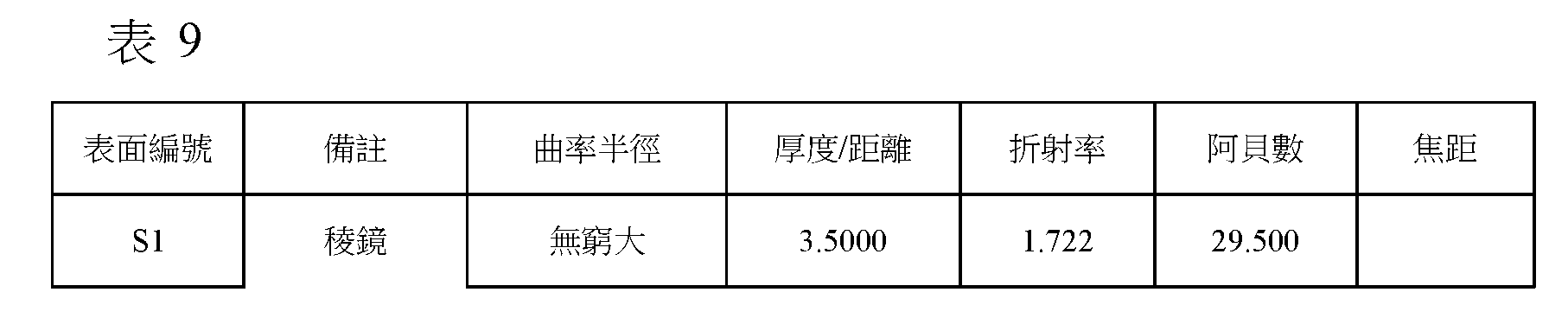
表9示出根據此實例的光學成像系統的透鏡特性,且表10示出根據此實例的光學成像系統的非球面值。圖15是以上配置的光學成像系統500的像差曲線。
Table 9 shows lens characteristics of the optical imaging system according to this example, and Table 10 shows aspheric surface values of the optical imaging system according to this example. FIG. 15 is an aberration curve of the


將參照圖16及圖17闡述根據第六實例的光學成像系統。 An optical imaging system according to a sixth example will be explained with reference to FIGS. 16 and 17 .
光學成像系統600包括稜鏡P、第一透鏡610、第二透鏡620、第三透鏡630、第四透鏡640及第五透鏡650。
The
第一透鏡610具有正的折射力。第一透鏡610具有物側表面為凸的且像側表面為凸的形狀。第二透鏡620具有正的折射力。第二透鏡620具有物側表面為凹的且像側表面為凸的形狀。第三透鏡630具有負的折射力。第三透鏡630具有物側表面為凹的且像側表面為凹的形狀。第四透鏡640具有正的折射力。第四
透鏡640具有物側表面為凸的且像側表面為凸的形狀。第五透鏡650具有負的折射力。第五透鏡650具有物側表面為凹的且像側表面為凸的形狀。
The
光學成像系統600包括稜鏡P、光闌ST、濾光片670及影像感測器680。
The
所述光學成像系統包括稜鏡P作為用於折疊或折射光學路徑的工具。稜鏡P將在第一光軸C1的方向上入射的光折疊於第二光軸C2的方向上。由稜鏡P折疊的第二光軸C2可與第一光軸C1實質上成直角。稜鏡P設置於第一透鏡610的物側上。以上配置的稜鏡P將自物體(對象)反射的光折射至影像感測器680。
The optical imaging system includes the FRP as a means for folding or refracting the optical path. The light P folds the light incident in the direction of the first optical axis C1 in the direction of the second optical axis C2. The second optical axis C2 folded by the P may be substantially at right angles to the first optical axis C1. The P is disposed on the object side of the
濾光片670設置於影像感測器680前方,以截止入射光中所包含的紅外線或類似物。影像感測器680包括多個光學感測器。以上配置的影像感測器680被配置成將光學訊號轉換成電性訊號。
The
表11示出根據此實例的光學成像系統的透鏡特性,且表12示出根據此實例的光學成像系統的非球面值。圖18是以上配置的光學成像系統600的像差曲線。
Table 11 shows lens characteristics of the optical imaging system according to this example, and Table 12 shows aspheric surface values of the optical imaging system according to this example. FIG. 18 is an aberration curve of the


將參照圖19及圖20闡述根據第七實例的光學成像系統。 An optical imaging system according to a seventh example will be explained with reference to FIGS. 19 and 20 .
光學成像系統700包括稜鏡P、第一透鏡710、第二透鏡720、第三透鏡730、第四透鏡740及第五透鏡750。
The
第一透鏡710具有正的折射力。第一透鏡710具有物側表面為凸的且像側表面為凸的形狀。第二透鏡720具有正的折射力。第二透鏡720具有物側表面為凸的且像側表面為凸的形狀。第三透鏡730具有負的折射力。第三透鏡730具有物側表面為凹的且像側表面為凹的形狀。第四透鏡740具有正的折射力。第四透鏡740具有物側表面為凸的且像側表面為凸的形狀。第五透鏡750具有負的折射力。第五透鏡750具有物側表面為凹的且像側表面為凸的形狀。
The
光學成像系統700包括稜鏡P、光闌ST、濾光片770及影像感測器780。
The
所述光學成像系統包括稜鏡P作為用於折疊或折射光學路徑的工具。稜鏡P將在第一光軸C1的方向上入射的光折疊於第二光軸C2的方向上。由稜鏡P折疊的第二光軸C2可與第一光軸C1實質上成直角。稜鏡P設置於第一透鏡710的物側上。以上配置的稜鏡P將自物體(對象)反射的光折射至影像感測器780。
The optical imaging system includes the FRP as a means for folding or refracting the optical path. The light P folds the light incident in the direction of the first optical axis C1 in the direction of the second optical axis C2. The second optical axis C2 folded by the P may be substantially at right angles to the first optical axis C1. The P is disposed on the object side of the
濾光片770設置於影像感測器780前方,以截止入射光中所包含的紅外線或類似物。影像感測器780包括多個光學感測器。以上配置的影像感測器780被配置成將光學訊號轉換成電性訊號。
The
表13示出根據此實例的光學成像系統的透鏡特性,且表14示出根據此實例的光學成像系統的非球面值。圖21是以上配置的光學成像系統700的像差曲線。
Table 13 shows lens characteristics of the optical imaging system according to this example, and Table 14 shows aspheric surface values of the optical imaging system according to this example. FIG. 21 is an aberration curve of the


將參照圖22及圖23闡述根據第八實例的光學成像系統。 An optical imaging system according to an eighth example will be explained with reference to FIGS. 22 and 23 .
光學成像系統800包括稜鏡P、第一透鏡810、第二透鏡820、第三透鏡830、第四透鏡840及第五透鏡850。
The
第一透鏡810具有正的折射力。第一透鏡810具有物側表面為凸的且像側表面為凸的形狀。第二透鏡820具有負的折射力。第二透鏡820具有物側表面為凹的且像側表面為凹的形狀。第三透鏡830具有負的折射力。第三透鏡830具有物側表面為凹的且像側表面為凹的形狀。第四透鏡840具有正的折射力。第四透鏡840具有物側表面為凸的且像側表面為凸的形狀。第五透鏡850具有負的折射力。第五透鏡850具有物側表面為凹的且像側表面為凸的形狀。
The
光學成像系統800包括稜鏡P、光闌ST、濾光片870及影像感測器880。
The
所述光學成像系統包括稜鏡P作為用於折疊或折射光學路徑的工具。稜鏡P將在第一光軸C1的方向上入射的光折疊於第
二光軸C2的方向上。由稜鏡P折疊的第二光軸C2可與第一光軸C1實質上成直角。稜鏡P設置於第一透鏡810的物側上。以上配置的稜鏡P將自物體(對象)反射的光折射至影像感測器880。
The optical imaging system includes the FRP as a means for folding or refracting the optical path.稜鏡P folds the incident light in the direction of the first optical axis C1 on the second
In the direction of the second optical axis C2. The second optical axis C2 folded by the P may be substantially at right angles to the first optical axis C1. The P is disposed on the object side of the
濾光片870設置於影像感測器880前方,以截止入射光中所包含的紅外線或類似物。影像感測器880包括多個光學感測器。以上配置的影像感測器880被配置成將光學訊號轉換成電性訊號。
The
表15示出根據此實例的光學成像系統的透鏡特性,且表16示出根據此實例的光學成像系統的非球面值。圖24是以上配置的光學成像系統800的像差曲線。
Table 15 shows lens characteristics of the optical imaging system according to this example, and Table 16 shows aspheric surface values of the optical imaging system according to this example. FIG. 24 is an aberration curve of the


將參照圖25及圖26闡述根據第九實例的光學成像系 統。 An optical imaging system according to a ninth example will be described with reference to FIGS. 25 and 26 system.
光學成像系統900包括稜鏡P、第一透鏡910、第二透鏡920、第三透鏡930、第四透鏡940及第五透鏡950。
The
第一透鏡910具有正的折射力。第一透鏡910具有物側表面為凸的且像側表面為凸的形狀。第二透鏡920具有負的折射力。第二透鏡920具有物側表面為凹的且像側表面為凸的形狀。第三透鏡930具有負的折射力。第三透鏡930具有物側表面為凹的且像側表面為凹的形狀。第四透鏡940具有正的折射力。第四透鏡940具有物側表面為凸的且像側表面為凸的形狀。第五透鏡950具有負的折射力。第五透鏡950具有物側表面為凹的且像側表面為凸的形狀。
The
光學成像系統900包括稜鏡P、光闌ST、濾光片970及影像感測器980。
The
所述光學成像系統包括稜鏡P作為用於折疊或折射光學路徑的工具。稜鏡P將在第一光軸C1的方向上入射的光折疊於第二光軸C2的方向上。由稜鏡P折疊的第二光軸C2可與第一光軸C1實質上成直角。稜鏡P設置於第一透鏡910的物側上。以上配置的稜鏡P將自物體(對象)反射的光折射至影像感測器980。
The optical imaging system includes the FRP as a means for folding or refracting the optical path. The light P folds the light incident in the direction of the first optical axis C1 in the direction of the second optical axis C2. The second optical axis C2 folded by the P may be substantially at right angles to the first optical axis C1. The P is disposed on the object side of the
濾光片970設置於影像感測器980前方,以截止入射光中所包含的紅外線或類似物。影像感測器980包括多個光學感測器。以上配置的影像感測器980被配置成將光學訊號轉換成電性訊號。
The
表17示出根據此實例的光學成像系統的透鏡特性,且表18示出根據此實例的光學成像系統的非球面值。圖27是以上配置的光學成像系統900的像差曲線。
Table 17 shows lens characteristics of the optical imaging system according to this example, and Table 18 shows aspheric surface values of the optical imaging system according to this example. FIG. 27 is an aberration curve of the


將參照圖28及圖29闡述根據第十實例的光學成像系統。 An optical imaging system according to a tenth example will be explained with reference to FIGS. 28 and 29 .
光學成像系統1000包括稜鏡P、第一透鏡1010、第二透鏡1020、第三透鏡1030、第四透鏡1040及第五透鏡1050。
The
第一透鏡1010具有正的折射力。第一透鏡1010具有物側表面為凸的且像側表面為凸的形狀。第二透鏡1020具有負的折射力。第二透鏡1020具有物側表面為凹的且像側表面為凸的形狀。第三透鏡1030具有負的折射力。第三透鏡1030具有物側表面為凹的且像側表面為凹的形狀。第四透鏡1040具有正的折射力。第
四透鏡1040具有物側表面為凸的且像側表面為凸的形狀。第五透鏡1050具有負的折射力。第五透鏡1050具有物側表面為凹的且像側表面為凸的形狀。
The
光學成像系統1000包括稜鏡P、光闌ST、濾光片1070、反射構件M及影像感測器1080。
The
所述光學成像系統包括稜鏡P作為用於折疊或折射光學路徑的工具。稜鏡P將在第一光軸C1的方向上入射的光折疊於第二光軸C2的方向上。由稜鏡P折疊的第二光軸C2可與第一光軸C1實質上成直角。稜鏡P設置於第一透鏡1010的物側上。以上配置的稜鏡P將自物體(對象)反射的光折射至反射構件M。反射構件M將藉由稜鏡P入射的光反射或折射至影像感測器1080。
The optical imaging system includes the FRP as a means for folding or refracting the optical path. The light P folds the light incident in the direction of the first optical axis C1 in the direction of the second optical axis C2. The second optical axis C2 folded by the P may be substantially at right angles to the first optical axis C1. The P is disposed on the object side of the
濾光片1070設置於影像感測器1080前方,以截止入射光中所包含的紅外線或類似物。影像感測器1080包括多個光學感測器。以上配置的影像感測器1080被配置成將光學訊號轉換成電性訊號。
The
表19示出根據此實例的光學成像系統的透鏡特性,且表20示出根據此實例的光學成像系統的非球面值。圖30是以上配置的光學成像系統1000的像差曲線。
Table 19 shows lens characteristics of the optical imaging system according to this example, and Table 20 shows aspheric surface values of the optical imaging system according to this example. FIG. 30 is an aberration curve of the


將參照圖31及圖32闡述根據第十一實例的光學成像系統。 An optical imaging system according to an eleventh example will be explained with reference to FIGS. 31 and 32 .
光學成像系統1100包括稜鏡P、第一透鏡1110、第二透鏡1120、第三透鏡1130、第四透鏡1140、第五透鏡1150及第六透鏡1160。
The
第一透鏡1110具有正的折射力。第一透鏡1110具有物側表面為凸的且像側表面為凸的形狀。第二透鏡1120具有負的折
射力。第二透鏡1120具有物側表面為凹的且像側表面為凹的形狀。第三透鏡1130具有負的折射力。第三透鏡1130具有物側表面為凹的且像側表面為凹的形狀。第四透鏡1140具有負的折射力。第四透鏡1140具有物側表面為凸的且像側表面為凹的形狀。第五透鏡1150具有正的折射力。第五透鏡1150具有物側表面為凸的且像側表面為凹的形狀。第六透鏡1160具有負的折射力。第六透鏡1160具有物側表面為凹的且像側表面為凸的形狀。
The
光學成像系統1100包括稜鏡P1、光闌ST、濾光片1170、反射構件M及影像感測器1180。
The
所述光學成像系統包括稜鏡P作為用於折疊或折射光學路徑的工具。稜鏡P將在第一光軸C1的方向上入射的光折疊於第二光軸C2的方向上。由稜鏡P折疊的第二光軸C2可與第一光軸C1實質上成直角。稜鏡P設置於第一透鏡1110的物側上。以上配置的稜鏡P將自物體(對象)反射的光折射至反射構件M。反射構件M將藉由稜鏡P入射的光反射或折射至影像感測器1180。
The optical imaging system includes the FRP as a means for folding or refracting the optical path. The light P folds the light incident in the direction of the first optical axis C1 in the direction of the second optical axis C2. The second optical axis C2 folded by the P may be substantially at right angles to the first optical axis C1. The P is disposed on the object side of the
濾光片1170設置於影像感測器1180前方,以截止入射光中所包含的紅外線或類似物。影像感測器1180包括多個光學感測器。以上配置的影像感測器1180被配置成將光學訊號轉換成電性訊號。
The
表21示出根據此實例的光學成像系統的透鏡特性,且表22示出根據此實例的光學成像系統的非球面值。圖33是以上配置的光學成像系統1100的像差曲線。
Table 21 shows lens characteristics of the optical imaging system according to this example, and Table 22 shows aspheric surface values of the optical imaging system according to this example. FIG. 33 is an aberration curve of the


表23示出根據第一實例至第十一實例的所述光學成像系統的光學特性。 Table 23 shows the optical characteristics of the optical imaging systems according to the first to eleventh examples.


表24示出根據相應實例的透鏡的有效長軸半徑[毫米],且表25示出根據相應實例的透鏡的有效短軸半徑[毫米]。 Table 24 shows the effective major-axis radius [mm] of the lens according to the corresponding example, and Table 25 shows the effective minor-axis radius [mm] of the lens according to the corresponding example.

表25

表26及表27示出根據第一實例至第十一實例的所述光學成像系統的條件表達式值。如可自表26及表27看出,根據第一實例至第十一實例的所述光學成像系統滿足上述條件表達式中的所有者。 Table 26 and Table 27 show conditional expression values of the optical imaging systems according to the first to eleventh examples. As can be seen from Table 26 and Table 27, the optical imaging systems according to the first to eleventh examples satisfy the owner in the above conditional expressions.


根據各種實例的所述光學成像系統包括具有圖34及圖35中所示形狀的透鏡以及間隙維持構件。作為參考,在圖34中僅示出第一透鏡的形狀,但應注意,第二透鏡至第七透鏡亦可被配置成具有在圖34中示出的形狀。 The optical imaging system according to various examples includes a lens having the shape shown in FIGS. 34 and 35 and a gap maintaining member. For reference, only the shape of the first lens is shown in FIG. 34 , but it should be noted that the second to seventh lenses may also be configured to have the shapes shown in FIG. 34 .
第一透鏡L1可被配置成在與光軸交叉的第一方向及第二方向上具有不同的長度。舉例而言,在第一透鏡L1中,第一方向上的有效半徑(下文中稱為長軸有效半徑)L1S1el可大於第二方向上的有效半徑(下文中稱為短軸有效半徑)L1S1es。第一透鏡L1的一個表面可以直線形式形成。舉例而言,如圖34中所示,平 行於第一透鏡L1的長軸有效半徑的兩個側表面可以直線形成。在第一透鏡L1中線性形成的範圍可被限制至預先確定的尺寸。舉例而言,在光軸中心C2與第一透鏡L1的線性部分的兩端二者之間形成的角度2θ可在10度至92度範圍內選擇。 The first lens L1 may be configured to have different lengths in a first direction crossing the optical axis and a second direction. For example, in the first lens L1, the effective radius in the first direction (hereinafter referred to as the major-axis effective radius) L1S1el may be greater than the effective radius in the second direction (hereinafter referred to as the minor-axis effective radius) L1S1es. One surface of the first lens L1 may be formed in a straight line. For example, as shown in Figure 34, the flat Both side surfaces running along the long-axis effective radius of first lens L1 may be formed in a straight line. A range linearly formed in the first lens L1 may be limited to a predetermined size. For example, the angle 2θ formed between the optical axis center C2 and both ends of the linear portion of the first lens L1 can be selected within a range of 10 degrees to 92 degrees.
如圖35中所示,間隙維持構件SP可以實質上矩形的形狀形成。舉例而言,間隙維持構件SP在第一方向上的長度SPX1可大於間隙維持構件SP在第二方向上的長度SPY1。間隙維持構件SP的孔在透鏡的有效直徑的形式上可實質上相同或相似。如圖35中所示,根據此實例的間隙維持構件SP的孔可具有一對直的平行線及一對曲線。在間隙維持構件SP的孔中,第一方向上的長度SPX2可大於第二方向上的長度SPY2。 As shown in FIG. 35 , the gap maintaining member SP may be formed in a substantially rectangular shape. For example, the length SPX1 of the gap maintaining member SP in the first direction may be greater than the length SPY1 of the gap maintaining member SP in the second direction. The apertures of the gap maintaining member SP may be substantially the same or similar in terms of the effective diameter of the lens. As shown in FIG. 35 , the hole of the gap maintaining member SP according to this example may have a pair of straight parallel lines and a pair of curved lines. In the hole of the gap maintaining member SP, the length SPX2 in the first direction may be greater than the length SPY2 in the second direction.
根據各種實例的光學成像系統20可安裝於小終端中。舉例而言,如圖36至圖39中所示,根據上述實例的所述光學成像系統中的至少一者可安裝於小終端10的後表面或前表面上。
The
小終端10可包括多個光學成像系統20、30、40及50。作為實例,如圖36中所示,小終端10可包括用於捕獲長距離景象的光學成像系統20及用於捕獲短距離景象的光學成像系統30。作為另一實例,如圖37及圖39中所示,小終端10可包括用於捕獲長距離景象的光學成像系統20及用於捕獲短距離景象的兩個光學成像系統30及40。作為另一實例,小終端10可包括用於捕獲長距離景象的光學成像系統20及彼此具有不同焦距的光學成像系統30、40及50。
The
如圖36至圖39中所示,光學成像系統20、30、40及50的排列形式可被以各種方式修改。
As shown in FIGS. 36 to 39, the arrangement form of the
如上所述,可實施一種可在具有長的焦距的同時安裝於薄化的小型終端中的光學成像系統。 As described above, it is possible to implement an optical imaging system that can be installed in a thinned and compact terminal while having a long focal length.
儘管本揭露包括具體實例,然而將在理解本申請案的揭露內容之後顯而易見,在不背離申請專利範圍及其等效範圍的精神及範圍的條件下,可對該些實例作出形式及細節上的各種改變。本文中所闡述的實例欲被視為僅為闡述性的,而非用於限制目的。對每一實例中的特徵或態樣的說明欲被視為適用於其他實例中的相似特徵或態樣。若所闡述的技術被以不同的次序執行,及/或若所闡述的系統、架構、裝置或電路中的組件被以不同的方式組合及/或被其他組件或其等效物替換或補充,則可達成適合的結果。因此,本揭露的範圍不由詳細說明界定,而是由申請專利範圍及其等效範圍界定,且申請專利範圍的範圍及其等效範圍內的所有變型均欲被理解為包括於本揭露中。 Although this disclosure includes specific examples, it will be apparent upon reading the disclosure of this application that changes in form and details may be made to these examples without departing from the spirit and scope of claims and equivalents thereof. Various changes. The examples set forth herein are intended to be considered as illustrative only and not for purposes of limitation. Descriptions of features or aspects within each example are intended to apply to similar features or aspects in the other examples. If the described techniques are performed in a different order, and/or if components of the described system, architecture, device, or circuit are combined in a different manner and/or are replaced or supplemented by other components or their equivalents, suitable results can be achieved. Therefore, the scope of the present disclosure is defined not by the detailed description but by the scope of the patent claims and its equivalents, and all modifications within the scope of the patent claims and their equivalents are intended to be included in the present disclosure.
100:光學成像系統 100: Optical imaging system
110:第一透鏡 110: first lens
120:第二透鏡 120: second lens
130:第三透鏡 130: third lens
140:第四透鏡 140: Fourth lens
150:第五透鏡 150: fifth lens
160:第六透鏡 160: sixth lens
170:濾光片 170: filter
180:影像感測器 180: image sensor
ST:光闌 ST: aperture
Claims (16)
Applications Claiming Priority (2)
| Application Number | Priority Date | Filing Date | Title |
|---|---|---|---|
| KR20190107270 | 2019-08-30 | ||
| KR10-2019-0107270 | 2019-08-30 |
Publications (2)
| Publication Number | Publication Date |
|---|---|
| TW202119079A TW202119079A (en) | 2021-05-16 |
| TWI809306B true TWI809306B (en) | 2023-07-21 |
Family
ID=74682674
Family Applications (2)
| Application Number | Title | Priority Date | Filing Date |
|---|---|---|---|
| TW112123375A TWI861953B (en) | 2019-08-30 | 2020-08-28 | Optical imaging system and portable electronic device |
| TW109129607A TWI809306B (en) | 2019-08-30 | 2020-08-28 | Optical imaging system and portable electronic device |
Family Applications Before (1)
| Application Number | Title | Priority Date | Filing Date |
|---|---|---|---|
| TW112123375A TWI861953B (en) | 2019-08-30 | 2020-08-28 | Optical imaging system and portable electronic device |
Country Status (4)
| Country | Link |
|---|---|
| US (2) | US11940599B2 (en) |
| KR (2) | KR102513955B1 (en) |
| CN (3) | CN112444949B (en) |
| TW (2) | TWI861953B (en) |
Families Citing this family (4)
| Publication number | Priority date | Publication date | Assignee | Title |
|---|---|---|---|---|
| JP6905650B1 (en) * | 2021-03-24 | 2021-07-21 | ジョウシュウシ レイテック オプトロニクス カンパニーリミテッド | Imaging lens |
| KR20230031735A (en) * | 2021-08-27 | 2023-03-07 | 엘지이노텍 주식회사 | Optical module |
| TWI837954B (en) * | 2022-11-18 | 2024-04-01 | 大立光電股份有限公司 | Photographing system lens assembly, image capturing unit and electronic device |
| TW202429156A (en) * | 2022-12-11 | 2024-07-16 | 以色列商核心光電有限公司 | Refractive and hybrid lenses for compact folded tele cameras |
Citations (4)
| Publication number | Priority date | Publication date | Assignee | Title |
|---|---|---|---|---|
| TW201736898A (en) * | 2016-04-15 | 2017-10-16 | 大立光電股份有限公司 | Optical imaging lens assembly, image capturing device and electronic device |
| US20180081152A1 (en) * | 2015-06-09 | 2018-03-22 | Zhejiang Sunny Optics Co., Ltd. | Imaging Lens Assembly |
| TW201819974A (en) * | 2016-11-24 | 2018-06-01 | 大立光電股份有限公司 | Photographing lens assembly, image capturing unit and electronic device |
| TW201830082A (en) * | 2017-02-08 | 2018-08-16 | 大立光電股份有限公司 | Photographing optical lens assembly, image capturing unit and electronic device |
Family Cites Families (21)
| Publication number | Priority date | Publication date | Assignee | Title |
|---|---|---|---|---|
| US1584271A (en) * | 1923-01-13 | 1926-05-11 | Bertele Ludwig | Photographic lens |
| JP4197994B2 (en) * | 2003-06-19 | 2008-12-17 | コニカミノルタオプト株式会社 | Imaging device |
| KR100800811B1 (en) | 2006-06-23 | 2008-02-01 | 삼성전자주식회사 | Zoom lens system |
| CN101771816A (en) * | 2008-12-27 | 2010-07-07 | 鸿富锦精密工业(深圳)有限公司 | Portable electronic device and imaging method |
| CN101923204A (en) * | 2009-06-16 | 2010-12-22 | 鸿富锦精密工业(深圳)有限公司 | Projection lens |
| CN103430074B (en) * | 2011-03-18 | 2016-01-20 | 富士胶片株式会社 | Imaging lens and imaging device |
| US9274311B2 (en) * | 2014-01-13 | 2016-03-01 | Genius Electronic Optical Co., Ltd. | Compact narrow field of view lenses for mobile devices |
| TWI531815B (en) | 2014-12-30 | 2016-05-01 | 大立光電股份有限公司 | Photographing optical lens assembly, image capturing device and electronic device |
| JP5843374B2 (en) * | 2015-06-24 | 2016-01-13 | 日立マクセル株式会社 | Imaging lens system |
| US10523854B2 (en) * | 2015-06-25 | 2019-12-31 | Intel Corporation | Array imaging system having discrete camera modules and method for manufacturing the same |
| JP2017097185A (en) * | 2015-11-25 | 2017-06-01 | 奇景光電股▲分▼有限公司 | Array lens system |
| TWI618944B (en) | 2016-04-29 | 2018-03-21 | 大立光電股份有限公司 | Optical image system, image capturing device and electronic device |
| JP6758971B2 (en) | 2016-07-19 | 2020-09-23 | キヤノン株式会社 | Zoom lens and imaging device with it |
| TWI607238B (en) * | 2016-08-22 | 2017-12-01 | 大立光電股份有限公司 | Optical camera system group, image capturing device and electronic device |
| US10802251B2 (en) * | 2016-08-23 | 2020-10-13 | Largan Precision Co., Ltd. | Photographing optical lens assembly, image capturing apparatus and electronic device |
| KR102483092B1 (en) | 2016-12-28 | 2022-12-30 | 삼성전기주식회사 | Optical system |
| KR101901701B1 (en) * | 2016-12-28 | 2018-09-27 | 삼성전기 주식회사 | Optical system |
| TWI629503B (en) | 2017-06-14 | 2018-07-11 | 大立光電股份有限公司 | Image capturing lens system, image capturing unit and electronic device |
| TWI629531B (en) * | 2017-10-25 | 2018-07-11 | 大立光電股份有限公司 | Imaging lens assembly, imaging apparatus and electronic device |
| CN109960005A (en) | 2017-12-22 | 2019-07-02 | 南昌欧菲光电技术有限公司 | Pick-up lens and electronic device |
| CN110109236B (en) | 2019-06-13 | 2024-04-09 | 浙江舜宇光学有限公司 | Optical imaging lens and electronic device |
-
2020
- 2020-08-27 US US17/004,317 patent/US11940599B2/en active Active
- 2020-08-28 TW TW112123375A patent/TWI861953B/en active
- 2020-08-28 TW TW109129607A patent/TWI809306B/en active
- 2020-08-28 KR KR1020200109412A patent/KR102513955B1/en active IP Right Grant
- 2020-08-31 CN CN202010892779.8A patent/CN112444949B/en active Active
- 2020-08-31 CN CN202021863056.7U patent/CN214097942U/en active Active
- 2020-08-31 CN CN202210544346.2A patent/CN114721131A/en active Pending
-
2023
- 2023-03-17 KR KR1020230035066A patent/KR102748962B1/en active IP Right Grant
-
2024
- 2024-02-06 US US18/433,886 patent/US20240176111A1/en active Pending
Patent Citations (4)
| Publication number | Priority date | Publication date | Assignee | Title |
|---|---|---|---|---|
| US20180081152A1 (en) * | 2015-06-09 | 2018-03-22 | Zhejiang Sunny Optics Co., Ltd. | Imaging Lens Assembly |
| TW201736898A (en) * | 2016-04-15 | 2017-10-16 | 大立光電股份有限公司 | Optical imaging lens assembly, image capturing device and electronic device |
| TW201819974A (en) * | 2016-11-24 | 2018-06-01 | 大立光電股份有限公司 | Photographing lens assembly, image capturing unit and electronic device |
| TW201830082A (en) * | 2017-02-08 | 2018-08-16 | 大立光電股份有限公司 | Photographing optical lens assembly, image capturing unit and electronic device |
Also Published As
| Publication number | Publication date |
|---|---|
| TW202119079A (en) | 2021-05-16 |
| US11940599B2 (en) | 2024-03-26 |
| CN112444949B (en) | 2022-12-27 |
| TWI861953B (en) | 2024-11-11 |
| CN214097942U (en) | 2021-08-31 |
| US20240176111A1 (en) | 2024-05-30 |
| CN112444949A (en) | 2021-03-05 |
| CN114721131A (en) | 2022-07-08 |
| KR20210027183A (en) | 2021-03-10 |
| KR102513955B1 (en) | 2023-03-27 |
| TW202343062A (en) | 2023-11-01 |
| KR102748962B1 (en) | 2025-01-03 |
| US20210063701A1 (en) | 2021-03-04 |
| KR20230041994A (en) | 2023-03-27 |
Similar Documents
| Publication | Publication Date | Title |
|---|---|---|
| TWI797763B (en) | Optical imaging system and portable electronic device | |
| TWI809306B (en) | Optical imaging system and portable electronic device | |
| TWI795061B (en) | Optical imaging system | |
| TWI752609B (en) | Optical imaging system and portable electronic device | |
| CN111856721B (en) | Optical imaging system | |
| CN206532023U (en) | Optical imaging system | |
| CN110501804A (en) | optical imaging system | |
| TWI794651B (en) | Camera module and terminal device | |
| TWI804264B (en) | Optical imaging system | |
| KR102609152B1 (en) | Optical Imaging System | |
| TWM651054U (en) | Optical imaging system | |
| TW202503350A (en) | Optical imaging system | |
| TW202503345A (en) | Optical imaging system and portable electronic device |