TWM651054U - Optical imaging system - Google Patents
Optical imaging system Download PDFInfo
- Publication number
- TWM651054U TWM651054U TW112208314U TW112208314U TWM651054U TW M651054 U TWM651054 U TW M651054U TW 112208314 U TW112208314 U TW 112208314U TW 112208314 U TW112208314 U TW 112208314U TW M651054 U TWM651054 U TW M651054U
- Authority
- TW
- Taiwan
- Prior art keywords
- lens
- imaging system
- optical imaging
- object side
- convex
- Prior art date
Links
- 238000012634 optical imaging Methods 0.000 title claims abstract description 156
- 239000000463 material Substances 0.000 claims description 67
- 230000003287 optical effect Effects 0.000 claims description 30
- 239000011521 glass Substances 0.000 claims description 17
- 238000003384 imaging method Methods 0.000 claims description 17
- 230000005499 meniscus Effects 0.000 description 25
- 230000004075 alteration Effects 0.000 description 14
- 238000010586 diagram Methods 0.000 description 12
- 238000000034 method Methods 0.000 description 5
- 238000012986 modification Methods 0.000 description 3
- 230000004048 modification Effects 0.000 description 3
- 238000004519 manufacturing process Methods 0.000 description 2
- 230000000903 blocking effect Effects 0.000 description 1
- 238000010276 construction Methods 0.000 description 1
- 239000000758 substrate Substances 0.000 description 1
Images


Classifications
-
- G—PHYSICS
- G03—PHOTOGRAPHY; CINEMATOGRAPHY; ANALOGOUS TECHNIQUES USING WAVES OTHER THAN OPTICAL WAVES; ELECTROGRAPHY; HOLOGRAPHY
- G03B—APPARATUS OR ARRANGEMENTS FOR TAKING PHOTOGRAPHS OR FOR PROJECTING OR VIEWING THEM; APPARATUS OR ARRANGEMENTS EMPLOYING ANALOGOUS TECHNIQUES USING WAVES OTHER THAN OPTICAL WAVES; ACCESSORIES THEREFOR
- G03B17/00—Details of cameras or camera bodies; Accessories therefor
- G03B17/02—Bodies
- G03B17/17—Bodies with reflectors arranged in beam forming the photographic image, e.g. for reducing dimensions of camera
-
- G—PHYSICS
- G02—OPTICS
- G02B—OPTICAL ELEMENTS, SYSTEMS OR APPARATUS
- G02B13/00—Optical objectives specially designed for the purposes specified below
- G02B13/001—Miniaturised objectives for electronic devices, e.g. portable telephones, webcams, PDAs, small digital cameras
- G02B13/0015—Miniaturised objectives for electronic devices, e.g. portable telephones, webcams, PDAs, small digital cameras characterised by the lens design
- G02B13/002—Miniaturised objectives for electronic devices, e.g. portable telephones, webcams, PDAs, small digital cameras characterised by the lens design having at least one aspherical surface
- G02B13/0035—Miniaturised objectives for electronic devices, e.g. portable telephones, webcams, PDAs, small digital cameras characterised by the lens design having at least one aspherical surface having three lenses
-
- G—PHYSICS
- G02—OPTICS
- G02B—OPTICAL ELEMENTS, SYSTEMS OR APPARATUS
- G02B13/00—Optical objectives specially designed for the purposes specified below
- G02B13/001—Miniaturised objectives for electronic devices, e.g. portable telephones, webcams, PDAs, small digital cameras
- G02B13/0055—Miniaturised objectives for electronic devices, e.g. portable telephones, webcams, PDAs, small digital cameras employing a special optical element
- G02B13/0065—Miniaturised objectives for electronic devices, e.g. portable telephones, webcams, PDAs, small digital cameras employing a special optical element having a beam-folding prism or mirror
-
- G—PHYSICS
- G02—OPTICS
- G02B—OPTICAL ELEMENTS, SYSTEMS OR APPARATUS
- G02B9/00—Optical objectives characterised both by the number of the components and their arrangements according to their sign, i.e. + or -
- G02B9/12—Optical objectives characterised both by the number of the components and their arrangements according to their sign, i.e. + or - having three components only
Landscapes
- Physics & Mathematics (AREA)
- General Physics & Mathematics (AREA)
- Optics & Photonics (AREA)
- Lenses (AREA)
- Cameras In General (AREA)
Abstract
Description
[相關申請案的交叉參考] [Cross-reference to related applications]
本申請案主張於2022年11月9日在韓國智慧財產局提出申請的韓國專利申請案第10-2022-0148695號以及於2023年3月17日在韓國智慧財產局提出申請的韓國專利申請案第10-2023-0035167號的優先權權益,所述韓國專利申請案的全部揭露內容出於所有目的併入本案供參考。 This application claims Korean Patent Application No. 10-2022-0148695 filed with the Korean Intellectual Property Office on November 9, 2022, and Korean Patent Application No. 10-2022-0148695 filed with the Korean Intellectual Property Office on March 17, 2023 No. 10-2023-0035167, the entire disclosure of the Korean patent application is hereby incorporated by reference for all purposes.
以下說明是有關於一種光學成像系統。 The following description is about an optical imaging system.
在可攜式終端中已安裝了各種類型的相機模組,並且具體而言,對應用了具有長焦距的望遠透鏡的折疊式相機模組的需求正在增加。由於望遠透鏡具有長焦距,因此必須確保足夠的後焦距(back focal length,BFL)。然而,為獲得較長的BFL,相機模組的大小不可避免地增加,此為不利的。 Various types of camera modules have been installed in portable terminals, and specifically, demand for foldable camera modules applying a telephoto lens with a long focal length is increasing. Since the telephoto lens has a long focal length, it must ensure sufficient back focal length (BFL). However, to obtain a longer BFL, the size of the camera module inevitably increases, which is disadvantageous.
提供此新型內容是為了以簡化形式介紹下文在實施方式中所進一步闡述的一系列概念。此新型內容並不旨在辨識所請求保護的標的物的關鍵特徵或本質特徵,亦非旨在用於幫助確定所 請求保護的標的物的範圍。 This new content is provided to introduce a selection of concepts in a simplified form that are further discussed below in the Detailed Description. This novel content is not intended to identify key features or essential characteristics of the claimed subject matter, nor is it intended to be used to assist in determining the claimed subject matter. The scope of the subject matter claimed.
在一個一般態樣中,一種光學成像系統包括自物體側依序排列的第一透鏡、第二透鏡、第三透鏡、反射構件及影像感測器。反射構件包括至少兩個反射表面,所述至少兩個反射表面被配置成將穿過第一透鏡至第三透鏡並且入射於反射構件上的光的路徑改變至少兩次。 In a general aspect, an optical imaging system includes a first lens, a second lens, a third lens, a reflective component and an image sensor arranged in sequence from an object side. The reflective member includes at least two reflective surfaces configured to change a path of light passing through the first lens to the third lens and incident on the reflective member at least twice.
反射構件可為平行四邊形形狀的稜鏡。 The reflective member may be a parallelogram-shaped mirror.
第一透鏡及第二透鏡可各自具有正的折射力,並且第三透鏡可具有正的折射力或負的折射力。 The first lens and the second lens may each have positive refractive power, and the third lens may have positive refractive power or negative refractive power.
第一透鏡至第三透鏡中的至少一者可由塑膠材料製成。 At least one of the first lens to the third lens may be made of plastic material.
第一透鏡至第三透鏡中的任意一個透鏡可由塑膠材料製成,另一個透鏡可由玻璃材料製成,且其餘透鏡可由玻璃材料或塑膠材料製成。 Any one of the first lens to the third lens may be made of plastic material, another lens may be made of glass material, and the remaining lenses may be made of glass material or plastic material.
所述光學成像系統可滿足50<v1<90,其中v1是第一透鏡的阿貝數。 The optical imaging system can satisfy 50<v1<90, where v1 is the Abbe number of the first lens.
所述光學成像系統可滿足1<TTL/f<1.4,其中TTL是自第一透鏡的物體側表面至影像感測器的成像表面的距離,且f是所述光學成像系統的焦距。 The optical imaging system can satisfy 1<TTL/f<1.4, where TTL is the distance from the object side surface of the first lens to the imaging surface of the image sensor, and f is the focal length of the optical imaging system.
所述光學成像系統可滿足0.1<LL/PL<0.4,其中LL是自第一透鏡的物體側表面至第三透鏡的影像側表面的距離,且PL是光在反射構件中的路徑的長度。 The optical imaging system can satisfy 0.1<LL/PL<0.4, where LL is the distance from the object side surface of the first lens to the image side surface of the third lens, and PL is the length of the path of light in the reflective member.
第一透鏡的物體側表面及第三透鏡的物體側表面中的至 少一者可為凸的。 The object-side surface of the first lens and the object-side surface of the third lens One less can be convex.
第二透鏡的影像側表面及第三透鏡的影像側表面中的至少一者可為凹的。 At least one of the image-side surface of the second lens and the image-side surface of the third lens may be concave.
在另一一般態樣中,一種光學成像系統包括:多個透鏡,包括第一透鏡、第二透鏡及第三透鏡;影像感測器,具有成像表面;以及稜鏡,設置於所述多個透鏡與影像感測器之間並且包括多個反射表面,所述多個反射表面各自被配置成對光進行反射,其中0.1<LL/PL<0.4,其中LL是自第一透鏡的物體側表面至第三透鏡的影像側表面的距離,且PL是光在稜鏡中的路徑的長度。 In another general aspect, an optical imaging system includes: a plurality of lenses, including a first lens, a second lens, and a third lens; an image sensor having an imaging surface; and a sensor disposed on the plurality of lenses. between the lens and the image sensor and includes a plurality of reflective surfaces, each of the plurality of reflective surfaces is configured to reflect light, where 0.1<LL/PL<0.4, where LL is the object side surface from the first lens The distance to the image side surface of the third lens, and PL is the length of the path of light in the lens.
稜鏡可具有包含第一反射表面及第二反射表面的平行四邊形形狀。 The lens may have a parallelogram shape including a first reflective surface and a second reflective surface.
第一透鏡可具有正的折射力,並且第一透鏡的物體側表面可為凸的。 The first lens may have positive refractive power, and the object-side surface of the first lens may be convex.
所述光學成像系統可滿足50<v1<90,其中v1是第一透鏡的阿貝數。 The optical imaging system can satisfy 50<v1<90, where v1 is the Abbe number of the first lens.
所述光學成像系統可滿足0
所述光學成像系統可滿足0.02<BFL/f<1.0,其中BFL是在光軸上自第三透鏡的影像側表面至影像感測器的成像表面的距離,且f是光學成像系統的焦距。 The optical imaging system can satisfy 0.02<BFL/f<1.0, where BFL is the distance on the optical axis from the image side surface of the third lens to the imaging surface of the image sensor, and f is the focal length of the optical imaging system.
藉由閱讀以下詳細說明、圖式及申請專利範圍,其他特徵及態樣將顯而易見。 Other features and aspects will become apparent by reading the following detailed description, drawings and patent claims.
100、200、300、400、500、600、700、800、900、1000、1100、1200、1300、1400:光學成像系統 100, 200, 300, 400, 500, 600, 700, 800, 900, 1000, 1100, 1200, 1300, 1400: Optical imaging system
110、210、310、410、510、610、710、810、910、1010、1110、1210、1310、1410:第一透鏡 110, 210, 310, 410, 510, 610, 710, 810, 910, 1010, 1110, 1210, 1310, 1410: first lens
120、220、320、420、520、620、720、820、920、1020、1120、1220、1320、1420:第二透鏡 120, 220, 320, 420, 520, 620, 720, 820, 920, 1020, 1120, 1220, 1320, 1420: Second lens
130、230、330、430、530、630、730、830、930、1030、1130、1230、1330、1430:第三透鏡 130, 230, 330, 430, 530, 630, 730, 830, 930, 1030, 1130, 1230, 1330, 1430: third lens
140、240、340、440、540、640、740、840、940、1040、1140、1240、1340、1440:紅外截止濾光器 140, 240, 340, 440, 540, 640, 740, 840, 940, 1040, 1140, 1240, 1340, 1440: Infrared cut filter
150、250、350、450、550、650、750、850、950、1050、1150、1250、1350、1450:影像感測器 150, 250, 350, 450, 550, 650, 750, 850, 950, 1050, 1150, 1250, 1350, 1450: Image sensor
P:稜鏡 P:稜鏡
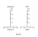
圖1是示出根據第一實例的光學成像系統的圖式。 FIG. 1 is a diagram showing an optical imaging system according to a first example.
圖2示出圖1所示光學成像系統的像差曲線。 FIG. 2 shows the aberration curve of the optical imaging system shown in FIG. 1 .
圖3是示出根據第二實例的光學成像系統的圖式。 3 is a diagram showing an optical imaging system according to a second example.
圖4示出圖3所示光學成像系統的像差曲線。 FIG. 4 shows the aberration curve of the optical imaging system shown in FIG. 3 .
圖5是示出根據第三實例的光學成像系統的圖式。 FIG. 5 is a diagram showing an optical imaging system according to a third example.
圖6示出圖5所示光學成像系統的像差曲線。 FIG. 6 shows the aberration curve of the optical imaging system shown in FIG. 5 .
圖7是示出根據第四實例的光學成像系統的圖式。 7 is a diagram showing an optical imaging system according to a fourth example.
圖8示出圖7所示光學成像系統的像差曲線。 FIG. 8 shows the aberration curve of the optical imaging system shown in FIG. 7 .
圖9是示出根據第五實例的光學成像系統的圖式。 FIG. 9 is a diagram showing an optical imaging system according to a fifth example.
圖10示出圖9所示光學成像系統的像差曲線。 FIG. 10 shows the aberration curve of the optical imaging system shown in FIG. 9 .
圖11是示出根據第六實例的光學成像系統的圖式。 FIG. 11 is a diagram showing an optical imaging system according to a sixth example.
圖12示出圖11所示光學成像系統的像差曲線。 FIG. 12 shows the aberration curve of the optical imaging system shown in FIG. 11 .
圖13是示出根據第七實例的光學成像系統的圖式。 FIG. 13 is a diagram showing an optical imaging system according to a seventh example.
圖14示出圖13所示光學成像系統的像差曲線。 FIG. 14 shows the aberration curve of the optical imaging system shown in FIG. 13 .
圖15是示出根據第八實例的光學成像系統的圖式。 FIG. 15 is a diagram showing an optical imaging system according to an eighth example.
圖16示出圖15所示光學成像系統的像差曲線。 FIG. 16 shows the aberration curve of the optical imaging system shown in FIG. 15 .
圖17是示出根據第九實例的光學成像系統的圖式。 FIG. 17 is a diagram showing an optical imaging system according to a ninth example.
圖18示出圖17所示光學成像系統的像差曲線。 FIG. 18 shows the aberration curve of the optical imaging system shown in FIG. 17 .
圖19是示出根據第十實例的光學成像系統的視圖。 FIG. 19 is a view showing an optical imaging system according to a tenth example.
圖20示出圖19所示光學成像系統的像差曲線。 FIG. 20 shows the aberration curve of the optical imaging system shown in FIG. 19 .
圖21是示出根據第十一實例的光學成像系統的圖式。 FIG. 21 is a diagram showing an optical imaging system according to an eleventh example.
圖22示出圖21所示光學成像系統的像差曲線。 FIG. 22 shows the aberration curve of the optical imaging system shown in FIG. 21 .
圖23是示出根據第十二實例的光學成像系統的圖式。 FIG. 23 is a diagram showing an optical imaging system according to a twelfth example.
圖24示出圖23所示光學成像系統的像差曲線。 FIG. 24 shows an aberration curve of the optical imaging system shown in FIG. 23 .
圖25是示出根據第十三實例的光學成像系統的視圖。 FIG. 25 is a view showing an optical imaging system according to a thirteenth example.
圖26示出圖25所示光學成像系統的像差曲線。 Figure 26 shows the aberration curve of the optical imaging system shown in Figure 25.
圖27是示出根據第十四實例的光學成像系統的圖式。 FIG. 27 is a diagram showing an optical imaging system according to a fourteenth example.
圖28示出圖27所示光學成像系統的像差曲線。 Figure 28 shows the aberration curve of the optical imaging system shown in Figure 27.
在圖式及詳細說明通篇中,相同的參考編號指代相同的元件。圖式可能並非按比例繪製,並且為清晰、例示及方便起見,可誇大圖式中的元件的相對大小、比例及繪示。 Throughout the drawings and detailed description, the same reference numbers refer to the same elements. The drawings may not be drawn to scale, and the relative sizes, proportions, and illustrations of elements in the drawings may be exaggerated for clarity, illustration, and convenience.
提供以下詳細說明以幫助讀者獲得對本文中所述方法、設備及/或系統的全面理解。然而,對於此項技術中具有通常知識者而言,本文中所述方法、設備及/或系統的各種改變、潤飾及等效形式將顯而易見。本文中所述的操作順序僅為實例,且不旨在限於本文中所陳述的操作順序,而是如對於此項技術中具有通常知識者而言將顯而易見,除必需以特定次序進行的操作以外,亦可有所改變。此外,為提高清晰性及簡潔性,對將為此項技術中具有通常知識者眾所習知的功能及構造的說明可不再予以贅述。 The following detailed description is provided to assist the reader in obtaining a comprehensive understanding of the methods, apparatus, and/or systems described herein. However, various modifications, modifications, and equivalents of the methods, apparatus, and/or systems described herein will be apparent to those of ordinary skill in the art. The order of operations set forth herein is an example only, and is not intended to be limited to the order of operations set forth herein, but as will be apparent to one of ordinary skill in the art, except for operations that must be performed in a specific order. , may also be changed. In addition, in order to enhance clarity and conciseness, descriptions of functions and constructions that would be well known to those of ordinary skill in the art may not be described again.
本文中所述特徵可以不同形式實施,且不被解釋為限於本文中所述實例。確切而言,提供本文中所述實例是為了使此揭露 內容將透徹及完整,並將向此項技術中具有通常知識者充分傳達本揭露內容的範圍。 Features described herein may be implemented in different forms and are not to be construed as limited to the examples set forth herein. Rather, the examples described in this article are provided to enable this disclosure The content will be thorough and complete, and will fully convey the scope of the disclosure to a person of ordinary skill in the art.
注意,在本文中,關於實例或實施例使用用語「可」(例如,關於實例或實施例可包括或實施何物)意指存在其中包括或實施此種特徵的至少一個實例或實施例,而所有實例及實施例並非僅限於此。 Note that herein, use of the word "may" with respect to an example or embodiment (eg, with respect to what the example or embodiment may include or implement) means that there is at least one example or embodiment in which such a feature is included or implemented, and All examples and embodiments are not limited thereto.
在說明書通篇中,當例如層、區或基板等元件被闡述為位於另一元件「上」、「連接至」或「耦合至」另一元件時,所述元件可直接位於所述另一元件「上」、直接「連接至」或直接「耦合至」所述另一元件,或者可存在介於其間的一或多個其他元件。反之,當一元件被闡述為「直接位於」另一元件「上」、「直接連接至」或「直接耦合至」另一元件時,則可不存在介於其間的其他元件。 Throughout this specification, when an element such as a layer, region, or substrate is referred to as being "on," "connected to" or "coupled to" another element, the element can be directly located on the other element. An element may be "on," directly "connected to," or directly "coupled to" another element, or there may be one or more other elements intervening therebetween. In contrast, when an element is referred to as being "directly on," "directly connected to" or "directly coupled to" another element, there may be no intervening elements present.
本文中所用的用語「及/或」包括相關聯列出項中的任一者及任意二或更多者的任意組合。 As used herein, the term "and/or" includes any one and any combination of two or more of the associated listed items.
儘管本文中可能使用例如「第一(first)」、「第二(second)」及「第三(third)」等用語來闡述各種構件、組件、區、層或區段,然而該些構件、組件、區、層或區段不受該些用語的限制。確切而言,該些用語僅用於區分各個構件、組件、區、層或區段。因此,在不背離實例的教示內容的條件下,本文中所述實例中所提及的第一構件、組件、區、層或區段亦可被稱為第二構件、組件、區、層或區段。 Although terms such as "first," "second," and "third" may be used herein to describe various components, components, regions, layers or sections, these components, A component, area, layer or section is not limited by these terms. Rather, these terms are only used to distinguish between various components, components, regions, layers or sections. Therefore, a first member, component, region, layer or section mentioned in the examples described herein could also be termed a second member, component, region, layer or section without departing from the teachings of the examples. section.
為易於說明,在本文中可使用例如「上方」、「上部的」、 「下方」及「下部的」等空間相對性用語來闡述圖中所示的一個元件相對於另一元件的關係。此種空間相對性用語旨在除圖中所繪示定向以外亦囊括裝置在使用或操作中的不同定向。舉例而言,若翻轉圖中的裝置,則被闡述為相對於另一元件位於「上方」或「上部」的元件此時將相對於所述另一元件位於「下方」或「下部」。因此,視裝置的空間定向而定,用語「上方」同時囊括上方與下方兩種定向。所述裝置亦可以其他方式定向(例如,旋轉90度或處於其他定向),且本文中所使用的空間相對性用語要相應地進行解釋。 For ease of explanation, terms such as “above”, “upper”, Spatially relative terms such as "below" and "lower" are used to describe the relationship of one element to another in the figures. These spatially relative terms are intended to encompass different orientations of the device in use or operation in addition to the orientation depicted in the figures. For example, if the device in the figures is turned over, then one element described as "above" or "upper" relative to another element would then be "below" or "lower" relative to the other element. Therefore, the term "above" encompasses both upper and lower orientations, depending on the spatial orientation of the device. The device may be otherwise oriented (e.g., rotated 90 degrees or at other orientations) and the spatially relative terms used herein interpreted accordingly.
本文中所使用的術語僅是為了闡述各種實例,而並非用於限制本揭露。除非上下文另外清楚地指示,否則冠詞「一(a、an)」及「所述(the)」旨在亦包括複數形式。用語「包括(comprises)」、「包含(includes)」及「具有(has)」規定所陳述的特徵、數目、操作、構件、元件及/或其組合的存在,但不排除一或多個其他特徵、數目、操作、構件、元件及/或其組合的存在或添加。 The terminology used herein is for the purpose of describing various examples only and is not intended to limit the disclosure. The articles "a, an" and "the" are intended to include the plural form as well, unless the context clearly indicates otherwise. The terms "comprises", "includes" and "has" specify the presence of stated features, numbers, operations, components, elements and/or combinations thereof, but do not exclude one or more other The presence or addition of features, numbers, operations, components, elements and/or combinations thereof.
由於製造技術及/或公差,圖中所示的形狀可能發生變化。因此,在本文中所述的實例並非僅限於圖式中所示的具體形狀,而是包括在製造期間發生的形狀變化。 Due to manufacturing techniques and/or tolerances, shapes shown may vary. Accordingly, the examples described herein are not limited to the specific shapes shown in the drawings but include changes in shapes that occur during manufacturing.
如在理解本申請案的揭露內容之後將顯而易見,本文中所述的實例的特徵可以各種方式組合。此外,儘管本文中所述的實例具有多種配置,然而如在理解本申請案的揭露內容之後將顯而易見,其他配置亦為可能的。 As will be apparent upon understanding the disclosure of this application, features of the examples described herein may be combined in various ways. Furthermore, although the examples described herein have various configurations, other configurations are possible, as will be apparent upon understanding the disclosure of this application.
在附圖中,為了便於闡釋,透鏡的厚度、大小及形狀已被略微誇大。具體而言,附圖中所示的球面表面或非球面表面的形狀是以實例方式示出的。亦即,球面表面或非球面表面的形狀並非僅限於在附圖中所示的形狀。 In the drawings, the thickness, size and shape of the lenses have been slightly exaggerated for ease of explanation. In particular, the shapes of spherical surfaces or aspherical surfaces shown in the drawings are shown by way of example. That is, the shape of the spherical surface or the aspherical surface is not limited to the shape shown in the drawings.
根據在本文中所揭露的各種實例的光學成像系統可包括沿著光軸排列的三個透鏡。舉例而言,光學成像系統可包括自物體側依序排列的第一透鏡、第二透鏡及第三透鏡。 An optical imaging system according to various examples disclosed herein may include three lenses arranged along an optical axis. For example, the optical imaging system may include a first lens, a second lens and a third lens arranged in sequence from the object side.
在各種實例中,第一透鏡指代最靠近物體(或對象)的透鏡,而第三透鏡指代最靠近成像表面(或影像感測器)的透鏡。 In various examples, the first lens refers to the lens closest to the object (or object), and the third lens refers to the lens closest to the imaging surface (or image sensor).
此外,每一透鏡的第一表面指代靠近物體側的表面(或物體側表面),而每一透鏡的第二表面指代靠近影像側的表面(或影像側表面)。 Furthermore, the first surface of each lens refers to the surface near the object side (or object-side surface), and the second surface of each lens refers to the surface near the image side (or image-side surface).
在各種實例中,透鏡的曲率半徑及厚度、TTL(自第一透鏡的物體側表面至成像表面的距離)、LL(自第一透鏡的物體側表面至第三透鏡的影像側表面的距離)、PL(光在稜鏡中的路徑的長度)、f(焦距)及IMH(成像表面的對角線長度的一半)皆由毫米(mm)表示。 In various examples, the radius of curvature and thickness of the lens, TTL (distance from the object side surface of the first lens to the imaging surface), LL (distance from the object side surface of the first lens to the image side surface of the third lens) , PL (the length of the path of light in the lens), f (focal length) and IMH (half the diagonal length of the imaging surface) are all expressed in millimeters (mm).
此外,在對各種實例的每一透鏡的說明中,透鏡的一個表面是凸的的含義為對應表面的近軸區(光軸附近的極小的區)是凸的,且透鏡的一個表面是凹的的含義為對應表面的近軸區是凹的。因此,即使在闡述透鏡的一個表面是凸的的情形中,透鏡的邊緣部分亦可為凹的。同樣,即使在闡述透鏡的一個表面是凹的的情形 中,透鏡的邊緣部分亦可為凸的。 Furthermore, in the description of each lens of various examples, one surface of the lens is convex means that the paraxial area (a very small area near the optical axis) of the corresponding surface is convex, and one surface of the lens is concave. The meaning of is that the paraxial region of the corresponding surface is concave. Therefore, even in the case where one surface of the lens is described as convex, the edge portion of the lens may be concave. Likewise, even in stating the case where one surface of the lens is concave , the edge portion of the lens can also be convex.
根據各種實例的光學成像系統可包括對入射光進行折射的光路徑改變單元。舉例而言,光路徑改變單元可為稜鏡,並且可設置於影像側上。舉例而言,稜鏡可設置於第三透鏡的後面(或者設置於第三透鏡的影像側上)。 The optical imaging system according to various examples may include a light path changing unit that refracts incident light. For example, the light path changing unit may be a lens, and may be disposed on the image side. For example, the lens may be disposed behind the third lens (or on the image side of the third lens).
此外,根據各種實例的光學成像系統可包括用於將經由光學系統入射的對象的影像轉換成電性訊號的影像感測器(或成像元件)、以及用於阻擋紅外線的紅外截止濾光器(infrared cut-off filter)。紅外截止濾光器可設置於稜鏡與影像感測器之間。 In addition, the optical imaging system according to various examples may include an image sensor (or imaging element) for converting an image of an object incident through the optical system into an electrical signal, and an infrared cut filter (or infrared cut filter) for blocking infrared rays. infrared cut-off filter). The infrared cut filter can be disposed between the camera and the image sensor.
此外,根據各種實例的光學成像系統可包括用於調節光量的光闌(stop)。舉例而言,光闌可設置於第一透鏡的物體側上或者設置於第二透鏡與第三透鏡之間。 Additionally, optical imaging systems according to various examples may include a stop for adjusting the amount of light. For example, the diaphragm may be provided on the object side of the first lens or between the second and third lenses.
根據各種實例,所述多個透鏡可由折射率不同於空氣的折射率的材料形成。舉例而言,第一透鏡至第三透鏡可由塑膠材料或玻璃材料形成。此外,根據各種實例的光學成像系統可包括由塑膠材料形成的透鏡,並且可視情況包括由玻璃材料形成的透鏡。 According to various examples, the plurality of lenses may be formed from a material with a refractive index different from that of air. For example, the first lens to the third lens may be formed of plastic material or glass material. Additionally, optical imaging systems according to various examples may include lenses formed from plastic materials and, optionally, glass materials.
所述多個透鏡中的至少一者可具有非球面表面。舉例而言,第一透鏡至第三透鏡中的至少一者可具有非球面表面。作為另外一種選擇,第一透鏡至第三透鏡中的每一者的第一表面或第二表面中的至少一者可為非球面的。第一透鏡至第三透鏡中的每一者的非球面表面可由以下方程式1表示。 At least one of the plurality of lenses may have an aspherical surface. For example, at least one of the first to third lenses may have an aspherical surface. Alternatively, at least one of the first surface or the second surface of each of the first through third lenses may be aspherical. The aspheric surface of each of the first to third lenses may be expressed by Equation 1 below.
[方程式1]

在方程式1中,c是透鏡的曲率半徑的倒數,K是圓錐常數,Y是自透鏡的非球面表面上的某一點至光軸的距離,A至J是四階非球面常數(fourth-order aspherical constant)至二十階非球面常數,且Z(或SAG)是在光軸方向上自透鏡的非球面表面上的某一點至透鏡的非球面表面的頂點的距離。 In Equation 1, c is the reciprocal of the radius of curvature of the lens, K is the conic constant, Y is the distance from a point on the aspheric surface of the lens to the optical axis, and A to J are the fourth-order aspheric constants. aspherical constant) to the twentieth-order aspherical constant, and Z (or SAG) is the distance from a point on the aspherical surface of the lens to the vertex of the aspherical surface of the lens in the direction of the optical axis.
根據各種實例的光學成像系統中所包括的第一透鏡至第三透鏡可自物體側依序具有正的折射力/負的折射力/正的或負的折射力。此外,第一透鏡至第三透鏡中的至少一者可由塑膠材料形成,並且可視情況由玻璃材料形成。根據各種實例的光學成像系統可包括具有至少兩個反射表面的反射構件。舉例而言,反射構件可為平行四邊形形狀的稜鏡,並且所述稜鏡可設置於第三透鏡的影像側上,換言之設置於第三透鏡與影像感測器(或紅外截止濾光器)之間。 The first lens to the third lens included in the optical imaging system according to various examples may have positive refractive power/negative refractive power/positive or negative refractive power in order from the object side. In addition, at least one of the first lens to the third lens may be formed of a plastic material, and optionally a glass material. Optical imaging systems according to various examples may include a reflective member having at least two reflective surfaces. For example, the reflective member may be a parallelogram-shaped lens, and the lens may be disposed on the image side of the third lens, in other words, between the third lens and the image sensor (or infrared cut filter) between.
根據各種實例的光學成像系統可滿足以下條件表達式1至條件表達式9中的至少一者。 The optical imaging system according to various examples may satisfy at least one of the following Conditional Expression 1 to Conditional Expression 9.
[條件表達式1]1<TTL/f<1.4 [Conditional expression 1]1<TTL/f<1.4
[條件表達式2]50<v1<90 [Conditional expression 2]50<v1<90
[條件表達式3]0.1<LL/PL<0.4 [Conditional expression 3]0.1<LL/PL<0.4
[條件表達式4]0.2<f1/f<0.8 [Conditional expression 4]0.2<f1/f<0.8
[條件表達式5]-20<f2/f<-0.3 [Conditional expression 5]-20<f2/f<-0.3
[條件表達式6]-3.5<f3/f<6.2 [Conditional expression 6]-3.5<f3/f<6.2
[條件表達式7]0
[條件表達式8]0.80
[條件表達式9]0.02<BFL/f<1.0 [Conditional expression 9]0.02<BFL/f<1.0
在上述條件表達式中,TTL是自第一透鏡的物體側表面至成像表面的距離,f是光學成像系統的焦距,v1是第一透鏡的阿貝數,且LL是自第一透鏡的物體側表面至第三透鏡的影像側表面的距離,PL是光在稜鏡中的路徑的長度,且BFL是自第三透鏡的影像側表面至成像表面的距離。 In the above conditional expression, TTL is the distance from the object side surface of the first lens to the imaging surface, f is the focal length of the optical imaging system, v1 is the Abbe number of the first lens, and LL is the object from the first lens The distance from the side surface to the image side surface of the third lens, PL is the length of the path of light in the lens, and BFL is the distance from the image side surface of the third lens to the imaging surface.
根據各種實例,稜鏡可具有平行四邊形形狀,並且包括供光入射於其上的入射表面、改變光的路徑的第一反射表面及第二反射表面、以及自其發射光的發射表面。PL可為在光軸上入射表面與第一反射表面之間的距離、在光軸上第一反射表面與第二反射表面之間的距離、以及在光軸上第二反射表面與發射表面之間的距離之和。此外,TTL可為在光軸上第一透鏡的物體側表面與第一反射表面之間的距離、在光軸上第一反射表面與第二反射表面之間的距離、以及在光軸上第二反射表面與成像表面之間的距離之和,且BFL可為在光軸上第三透鏡的影像側表面與第一反射表面之間的距離、在光軸上第一反射表面與第二反射表面之間的距離、以及在光軸上第二反射表面與成像表面之間的距離之和。 According to various examples, the frame may have a parallelogram shape and include an incident surface for light to be incident thereon, first and second reflective surfaces that change the path of the light, and an emission surface from which light is emitted. PL may be the distance between the incident surface and the first reflective surface on the optical axis, the distance between the first reflective surface and the second reflective surface on the optical axis, and the distance between the second reflective surface and the emitting surface on the optical axis. The sum of the distances between them. In addition, TTL may be a distance between the object side surface of the first lens and the first reflective surface on the optical axis, a distance between the first reflective surface and the second reflective surface on the optical axis, and a third reflective surface on the optical axis. The sum of the distances between the two reflective surfaces and the imaging surface, and BFL can be the distance between the image side surface of the third lens and the first reflective surface on the optical axis, the distance between the first reflective surface and the second reflective surface on the optical axis The sum of the distance between the surfaces and the distance on the optical axis between the second reflective surface and the imaging surface.
在下文中,將闡述根據各種示例性實例的光學成像系統。 In the following, optical imaging systems according to various illustrative examples will be explained.
首先,將參照圖1及圖2來闡述根據第一實例的光學成像系統。 First, the optical imaging system according to the first example will be explained with reference to FIGS. 1 and 2 .
根據第一實例的光學成像系統100可包括自物體側依序排列的第一透鏡110、第二透鏡120及第三透鏡130。
The
第一透鏡110可具有正的折射力,並且第一透鏡110的兩個表面皆可為凸的。舉例而言,第一透鏡110的第一表面及第二表面在近軸區中可為凸的。第二透鏡120可具有負的折射力,並且可具有朝向物體側凸出的彎月形狀。舉例而言,第二透鏡120的第一表面在近軸區中可為凸的,而第二透鏡120的第二表面在近軸區中可為凹的。第三透鏡130可具有正的折射力,並且可具有朝向物體側凸出的彎月形狀。舉例而言,第三透鏡130的第一表面在近軸區中可為凸的,而第三透鏡130的第二表面在近軸區中可為凹的。
The
光學成像系統100可包括由塑膠材料形成的透鏡。舉例而言,第一透鏡110、第二透鏡120及第三透鏡130皆可由塑膠材料形成。此外,第一透鏡110、第二透鏡120及第三透鏡130可由具有不同光學特性的塑膠材料形成。舉例而言,第一透鏡110、第二透鏡120及第三透鏡130的阿貝數可彼此不同。
此外,光學成像系統100可包括光闌(圖中未示出)、稜鏡P、紅外截止濾光器140及影像感測器150。舉例而言,光闌可設置於第一透鏡110的物體側上。稜鏡P可設置於第三透鏡130與紅外截止濾光器140之間,且入射於稜鏡P上的光的路徑可總共改變兩次。
In addition, the
下表1示出光學成像系統100的特性,且表2示出光學
成像系統100的非球面表面的值。
Table 1 below shows the characteristics of the


接下來,將參照圖3及圖4來闡述根據第二實例的光學成像系統。 Next, the optical imaging system according to the second example will be explained with reference to FIGS. 3 and 4 .
根據第二實例的光學成像系統200可包括自物體側依序排列的第一透鏡210、第二透鏡220及第三透鏡230。
The
第一透鏡210可具有正的折射力,並且第一透鏡210的兩個表面皆可為凸的。舉例而言,第一透鏡210的第一表面及第二表面在近軸區中可為凸的。第二透鏡220可具有負的折射力,並且第二透鏡220的兩個表面皆可為凹的。舉例而言,第二透鏡220的第一表面及第二表面在近軸區中可為凹的。第三透鏡230可具有負的折射力,並且可具有朝向物體側凸出的彎月形狀。舉例而言,第三透鏡230的第一表面在近軸區中可為凸的,而第三透鏡230的第二表面在近軸區中可為凹的。
The
光學成像系統200可包括由塑膠材料形成的透鏡。舉例而言,第一透鏡210、第二透鏡220及第三透鏡230皆可由塑膠材料形成。此外,根據第二實例,第一透鏡210、第二透鏡220及第
三透鏡230中的至少一些透鏡可由具有不同光學特性的塑膠材料形成。舉例而言,第三透鏡230的阿貝數可不同於第一透鏡210的阿貝數及第二透鏡220的阿貝數。
此外,光學成像系統200可包括光闌(圖中未示出)、稜鏡P、紅外截止濾光器240及影像感測器250。舉例而言,光闌可設置於第一透鏡210的物體側上。稜鏡P可設置於第三透鏡230與紅外截止濾光器240之間,且入射於稜鏡P上的光的路徑可總共改變兩次。
In addition, the
下表3示出光學成像系統200的特性,且表4示出光學成像系統200的非球面表面的值。
Table 3 below shows the characteristics of the


將參照圖5及圖6來闡述根據第三實例的光學成像系統。 The optical imaging system according to the third example will be explained with reference to FIGS. 5 and 6 .
根據第三實例的光學成像系統300可包括自物體側依序排列的第一透鏡310、第二透鏡320及第三透鏡330。
The
第一透鏡310可具有正的折射力,並且可具有朝向物體側凸出的彎月形狀。舉例而言,第一透鏡310的第一表面在近軸區中可為凸的,而第一透鏡310的第二表面在近軸區中可為凹的。第二透鏡320可具有負的折射力,並且可具有朝向物體側凸出的
彎月形狀。舉例而言,第二透鏡320的第一表面在近軸區中可為凸的,而第二透鏡320的第二表面在近軸區中可為凹的。第三透鏡330可具有正的折射力,並且可具有朝向物體側凸出的彎月形狀。舉例而言,第三透鏡330的第一表面在近軸區中可為凸的,而第三透鏡330的第二表面在近軸區中可為凹的。
The
光學成像系統300可包括由塑膠材料形成的透鏡。舉例而言,第一透鏡310及第二透鏡320可由塑膠材料形成,且第三透鏡330可由玻璃材料形成。此外,根據第三實例,第一透鏡310與第二透鏡320可由具有不同光學特性的塑膠材料形成。舉例而言,第一透鏡310的阿貝數與第二透鏡320的阿貝數可彼此不同。
此外,光學成像系統300可包括光闌(圖中未示出)、稜鏡P、紅外截止濾光器340及影像感測器350。舉例而言,光闌可設置於第二透鏡320的影像側上。稜鏡P可設置於第三透鏡330與紅外截止濾光器340之間,且入射於稜鏡P上的光的路徑可總共改變兩次。
In addition, the
下表5示出光學成像系統300的特性,且表6示出光學成像系統300的非球面表面的值。
Table 5 below shows the characteristics of the


將參照圖7及圖8來闡述根據第四實例的光學成像系統。 The optical imaging system according to the fourth example will be explained with reference to FIGS. 7 and 8 .
根據第四實例的光學成像系統400可包括自物體側依序排列的第一透鏡410、第二透鏡420及第三透鏡430。
The
第一透鏡410可具有正的折射力,並且可具有朝向物體側凸出的彎月形狀。舉例而言,第一透鏡410的第一表面在近軸區中可為凸的,而第一透鏡410的第二表面在近軸區中可為凹的。第二透鏡420可具有負的折射力,並且可具有朝向物體側凸出的彎月形狀。舉例而言,第二透鏡420的第一表面在近軸區中可為凸的,而第二透鏡420的第二表面在近軸區中可為凹的。第三透鏡430可具有正的折射力,並且可具有朝向物體側凸出的彎月形狀。舉例而言,第三透鏡430的第一表面在近軸區中可為凸的,而第三透鏡430的第二表面在近軸區中可為凹的。
The
光學成像系統400可包括由塑膠材料形成的透鏡。舉例而言,第一透鏡410可由玻璃材料形成,且第二透鏡420及第三透鏡430可由塑膠材料形成。此外,根據第四實例,第二透鏡420與第三透鏡430可由具有不同光學特性的塑膠材料形成。舉例而言,第二透鏡420的阿貝數與第三透鏡430的阿貝數可彼此不同。
此外,光學成像系統400可包括光闌(圖中未示出)、稜鏡P、紅外截止濾光器440及影像感測器450。舉例而言,光闌可設置於第一透鏡410的物體側上。稜鏡P可設置於第三透鏡430與紅外截止濾光器440之間,且入射於稜鏡P上的光的路徑可總共改變兩次。
In addition, the
下表7示出光學成像系統400的特性,且表8示出光學成像系統400的非球面表面的值。
Table 7 below shows the characteristics of the


將參照圖9及圖10來闡述根據第五實例的光學成像系統。 The optical imaging system according to the fifth example will be explained with reference to FIGS. 9 and 10 .
根據第五實例的光學成像系統500可包括自物體側依序排列的第一透鏡510、第二透鏡520及第三透鏡530。
The
第一透鏡510可具有正的折射力,並且第一透鏡510的兩個表面皆可為凸的。舉例而言,第一透鏡510的第一表面及第二表面在近軸區中可為凸的。第二透鏡520可具有負的折射力,並且可具有朝向物體側凸出的彎月形狀。舉例而言,第二透鏡520的第一表面在近軸區中可為凸的,而第二透鏡520的第二表面在近軸區中可為凹的。第三透鏡530可具有負的折射力,並且可具有朝向物體側凸出的彎月形狀。舉例而言,第三透鏡530的第一表面在近軸區中可為凸的,而第三透鏡530的第二表面在近軸區中可為凹的。
The
光學成像系統500可包括由塑膠材料形成的透鏡。舉例而言,第一透鏡510及第二透鏡520可由玻璃材料形成,且第三
透鏡530可由塑膠材料形成。
此外,光學成像系統500可包括光闌(圖中未示出)、稜鏡P、紅外截止濾光器540及影像感測器550。舉例而言,光闌可設置於第一透鏡510的物體側上。稜鏡P可設置於第三透鏡530與紅外截止濾光器540之間,且入射於稜鏡P上的光的路徑可總共改變兩次。
In addition, the
下表9示出光學成像系統500的特性,且表10示出光學成像系統500的非球面表面的值。
Table 9 below shows the characteristics of the


接下來,將參照圖11及圖12來闡述根據第六實例的光學成像系統。 Next, an optical imaging system according to a sixth example will be explained with reference to FIGS. 11 and 12 .
根據第六實例的光學成像系統600可包括自物體側依序排列的第一透鏡610、第二透鏡620及第三透鏡630。
The
第一透鏡610可具有正的折射力,並且第一透鏡610的兩個表面皆可為凸的。舉例而言,第一透鏡610的第一表面及第二表面在近軸區中可為凸的。第二透鏡620可具有負的折射力,並且可具有彎月形狀,第二透鏡620以所述彎月形狀朝向影像凸
出。舉例而言,第二透鏡620的第一表面在近軸區中可為凹的,而第二透鏡620的第二表面在近軸區中可為凸的。第三透鏡630可具有負的折射力,並且可具有朝向物體側凸出的彎月形狀。舉例而言,第三透鏡630的第一表面在近軸區中可為凸的,而第三透鏡630的第二表面在近軸區中可為凹的。
The
光學成像系統600可包括由塑膠材料形成的透鏡。舉例而言,第一透鏡610可由塑膠材料形成,且第二透鏡620及第三透鏡630可由玻璃材料形成。
此外,光學成像系統600可包括光闌(圖中未示出)、稜鏡P、紅外截止濾光器640及影像感測器650。舉例而言,光闌可設置於第一透鏡610的物體側上。稜鏡P可設置於第三透鏡630與紅外截止濾光器640之間,且入射於稜鏡P上的光的路徑可總共改變兩次。
In addition, the
下表11示出光學成像系統600的特性,且表12示出光學成像系統600的非球面表面的值。
Table 11 below shows the characteristics of the


接下來,將參照圖13及圖14來闡述根據第七實例的光 學成像系統。 Next, the optical method according to the seventh example will be explained with reference to FIGS. 13 and 14 imaging system.
根據第七實例的光學成像系統700可包括自物體側依序排列的第一透鏡710、第二透鏡720及第三透鏡730。
The
第一透鏡710可具有正的折射力,並且第一透鏡710的兩個表面皆可為凸的。舉例而言,第一透鏡710的第一表面及第二表面在近軸區中可為凸的。第二透鏡720可具有負的折射力,並且可具有朝向影像凸出的彎月形狀。舉例而言,第二透鏡720的第一表面在近軸區中可為凹的,而第二透鏡720的第二表面在近軸區中可為凸的。第三透鏡730可具有負的折射力,並且第三透鏡730的兩個表面皆可為凹的。舉例而言,第三透鏡730的第一表面及第二表面在近軸區中可為凹的。
The
光學成像系統700可包括由塑膠材料形成的透鏡。舉例而言,第一透鏡710、第二透鏡720及第三透鏡730皆可由塑膠材料形成。此外,根據第七實例,第一透鏡710、第二透鏡720及第三透鏡730中的至少一些透鏡可由具有不同光學特性的塑膠材料形成。舉例而言,第一透鏡710的阿貝數可不同於第二透鏡720的阿貝數及第三透鏡730的阿貝數。
此外,光學成像系統700可包括光闌(圖中未示出)、稜鏡P、紅外截止濾光器740及影像感測器750。舉例而言,光闌可設置於第一透鏡710的物體側上。稜鏡P可設置於第三透鏡730與紅外截止濾光器740之間,且入射於稜鏡P上的光的路徑可總共改變兩次。
In addition, the
下表13示出光學成像系統700的特性,且表14示出光學成像系統700的非球面表面的值。
Table 13 below shows the characteristics of the


將參照圖15及圖16來闡述根據第八實例的光學成像系統。 The optical imaging system according to the eighth example will be explained with reference to FIGS. 15 and 16 .
根據第八實例的光學成像系統800可包括自物體側依序排列的第一透鏡810、第二透鏡820及第三透鏡830。
The
第一透鏡810可具有正的折射力,並且第一透鏡810的兩個表面皆可為凸的。舉例而言,第一透鏡810的第一表面及第二表面在近軸區中可為凸的。第二透鏡820可具有負的折射力,並且第二透鏡820的兩個表面皆可為凹的。舉例而言,第二透鏡820的第一表面及第二表面在近軸區中可為凹的。第三透鏡830可具有負的折射力,並且可具有朝向物體側凸出的彎月形狀。舉例而言,第三透鏡830的第一表面在近軸區中可為凸的,而第三透鏡830的第二表面在近軸區中可為凹的。
The
光學成像系統800可包括由塑膠材料形成的透鏡。舉例而言,第一透鏡810、第二透鏡820及第三透鏡830皆可由塑膠材料形成。此外,根據第八實例,第一透鏡810、第二透鏡820及第
三透鏡830中的至少一些透鏡可由具有不同光學特性的塑膠材料形成。舉例而言,第三透鏡830的阿貝數可不同於第一透鏡810的阿貝數及第二透鏡820的阿貝數。
此外,光學成像系統800可包括光闌(圖中未示出)、稜鏡P、紅外截止濾光器840及影像感測器850。舉例而言,光闌可設置於第三透鏡830的物體側上。稜鏡P可設置於第三透鏡830與紅外截止濾光器840之間,且入射於稜鏡P上的光的路徑可總共改變兩次。
In addition, the
下表15示出光學成像系統800的特性,且表16示出光學成像系統800的非球面表面的值。
Table 15 below shows the characteristics of the


將參照圖17及圖18來闡述根據第九實例的光學成像系統。 The optical imaging system according to the ninth example will be explained with reference to FIGS. 17 and 18 .
根據第九實例的光學成像系統900可包括自物體側依序排列的第一透鏡910、第二透鏡920及第三透鏡930。
The
第一透鏡910可具有正的折射力,並且第一透鏡910的兩個表面皆可為凸的。舉例而言,第一透鏡910的第一表面及第二表面在近軸區中可為凸的。第二透鏡920可具有負的折射力,
並且可具有朝向物體側凸出的彎月形狀。舉例而言,第二透鏡920的第一表面在近軸區中可為凸的,而第二透鏡920的第二表面在近軸區中可為凹的。第三透鏡930可具有負的折射力,並且可具有朝向物體側凸出的彎月形狀。舉例而言,第三透鏡930的第一表面在近軸區中可為凸的,而第三透鏡930的第二表面在近軸區中可為凹的。
The
光學成像系統900可包括由塑膠材料形成的透鏡。舉例而言,第一透鏡910可由玻璃材料形成,且第二透鏡920及第三透鏡930可由塑膠材料形成。此外,根據第九實例,第二透鏡920與第三透鏡930可由具有不同光學特性的塑膠材料形成。舉例而言,第二透鏡920的阿貝數與第三透鏡930的阿貝數可彼此不同。
此外,光學成像系統900可包括光闌(圖中未示出)、稜鏡P、紅外截止濾光器940及影像感測器950。舉例而言,光闌可設置於第二透鏡920的影像側上。稜鏡P可設置於第三透鏡930與紅外截止濾光器940之間,且入射於稜鏡P上的光的路徑可總共改變兩次。
In addition, the
下表17示出光學成像系統900的特性,且表18示出光學成像系統900的非球面表面的值。
Table 17 below shows the characteristics of the


將參照圖19及圖20來闡述根據第十實例的光學成像系統。 An optical imaging system according to a tenth example will be explained with reference to FIGS. 19 and 20 .
根據第十實例的光學成像系統1000可包括自物體側依序排列的第一透鏡1010、第二透鏡1020及第三透鏡1030。
The
第一透鏡1010可具有正的折射力,並且第一透鏡1010的兩個表面皆可為凸的。舉例而言,第一透鏡1010的第一表面及第二表面在近軸區中可為凸的。第二透鏡1020可具有負的折射力,並且第二透鏡1020的兩個表面皆可為凹的。舉例而言,第二透鏡1020的第一表面及第二表面在近軸區中可為凹的。第三透鏡1030可具有正的折射力,並且可具有朝向物體側凸出的彎月形狀。舉例而言,第三透鏡1030的第一表面在近軸區中可為凸的,而第三透鏡1030的第二表面在近軸區中可為凹的。
The
光學成像系統1000可包括由塑膠材料形成的透鏡。舉例而言,第一透鏡1010及第二透鏡1020可由塑膠材料形成,且第三透鏡1030可由玻璃材料形成。此外,根據第十實例,第一透鏡1010與第二透鏡1020可由具有不同光學特性的塑膠材料形成。舉例而言,第一透鏡1010的阿貝數與第二透鏡1020的阿貝數可彼此不同。
此外,光學成像系統1000可包括光闌(圖中未示出)、稜鏡P、紅外截止濾光器1040及影像感測器1050。舉例而言,光
闌可設置於第一透鏡1010的物體側上。稜鏡P可設置於第三透鏡1030與紅外截止濾光器1040之間,且入射於稜鏡P上的光的路徑可總共改變兩次。
In addition, the
下表19示出光學成像系統1000的特性,且表20示出光學成像系統1000的非球面表面的值。
Table 19 below shows the characteristics of the

[表20]

接下來,將參照圖21及圖22來闡述根據第十一實例的光學成像系統。 Next, an optical imaging system according to an eleventh example will be explained with reference to FIGS. 21 and 22 .
根據第十一實例的光學成像系統1100可包括自物體側依序排列的第一透鏡1110、第二透鏡1120及第三透鏡1130。
The
第一透鏡1110可具有正的折射力,並且第一透鏡1110的兩個表面皆可為凸的。舉例而言,第一透鏡1110的第一表面及第二表面在近軸區中可為凸的。第二透鏡1120可具有負的折射力,並且可具有彎月形狀,第二透鏡1120以所述彎月形狀朝向影像凸出。舉例而言,第二透鏡1120的第一表面在近軸區中可為凹的,而第二透鏡1120的第二表面在近軸區中可為凸的。第三透鏡1130可具有負的折射力,並且可具有朝向物體側凸出的彎月形狀。舉例而言,第三透鏡1130的第一表面在近軸區中可為凸的,而第三透
鏡1130的第二表面在近軸區中可為凹的。
The
光學成像系統1100可包括由塑膠材料形成的透鏡。舉例而言,第一透鏡1110可由玻璃材料形成,且第二透鏡1120及第三透鏡1130可由塑膠材料形成。此外,根據第十一實例,第二透鏡1120與第三透鏡1130可由具有不同光學特性的塑膠材料形成。舉例而言,第二透鏡1120的阿貝數與第三透鏡1130的阿貝數可彼此不同。
此外,光學成像系統1100可包括光闌(圖中未示出)、稜鏡P、紅外截止濾光器1140及影像感測器1150。舉例而言,光闌可設置於第一透鏡1110的物體側上。稜鏡P可設置於第三透鏡1130與紅外截止濾光器1140之間,且入射於稜鏡P上的光的路徑可總共改變兩次。
In addition, the
下表21示出光學成像系統1100的特性,且表22示出光學成像系統1100的非球面表面的值。
Table 21 below shows the characteristics of the


接下來,將參照圖23及圖24來闡述根據第十二實例的光學成像系統。 Next, an optical imaging system according to a twelfth example will be explained with reference to FIGS. 23 and 24 .
根據第十二實例的光學成像系統1200可包括自物體側
依序排列的第一透鏡1210、第二透鏡1220及第三透鏡1230。
The
第一透鏡1210可具有正的折射力,並且第一透鏡1210的兩個表面皆可為凸的。舉例而言,第一透鏡1210的第一表面及第二表面在近軸區中可為凸的。第二透鏡1220可具有負的折射力,並且第二透鏡1220的兩個表面皆可為凹的。舉例而言,第二透鏡1220的第一表面及第二表面在近軸區中可為凹的。第三透鏡1230可具有負的折射力,並且可具有朝向物體側凸出的彎月形狀。舉例而言,第三透鏡1230的第一表面在近軸區中可為凸的,而第三透鏡1230的第二表面在近軸區中可為凹的。
The
光學成像系統1200可包括由塑膠材料形成的透鏡。舉例而言,第一透鏡1210可由玻璃材料形成,且第二透鏡1220及第三透鏡1230可由塑膠材料形成。此外,根據第十二實例,第二透鏡1220與第三透鏡1230可由具有不同光學特性的塑膠材料形成。舉例而言,第二透鏡1220的阿貝數與第三透鏡1230的阿貝數可彼此不同。
此外,光學成像系統1200可包括光闌(圖中未示出)、稜鏡P、紅外截止濾光器1240及影像感測器1250。舉例而言,光闌可設置於第一透鏡1210的物體側上。稜鏡P可設置於第三透鏡1230與紅外截止濾光器1240之間,且入射於稜鏡P上的光的路徑可總共改變兩次。
In addition, the
下表23示出光學成像系統1200的特性,且表24示出光學成像系統1200的非球面表面的值。
Table 23 below shows the characteristics of the


將參照圖25及圖26來闡述根據第十三實例的光學成像系統。 The optical imaging system according to the thirteenth example will be explained with reference to FIGS. 25 and 26 .
根據第十三實例的光學成像系統1300可包括自物體側依序排列的第一透鏡1310、第二透鏡1320及第三透鏡1330。
The
第一透鏡1310可具有正的折射力,並且第一透鏡1310的兩個表面皆可為凸的。舉例而言,第一透鏡1310的第一表面及第二表面在近軸區中可為凸的。第二透鏡1320可具有負的折射力,並且可具有朝向物體側凸出的彎月形狀。舉例而言,第二透鏡1320的第一表面在近軸區中可為凸的,而第二透鏡1320的第二表面在近軸區中可為凹的。第三透鏡1330可具有負的折射力,並且可具有朝向物體側凸出的彎月形狀。舉例而言,第三透鏡1330的第一表面在近軸區中可為凸的,而第三透鏡1330的第二表面在近軸區中可為凹的。
The
光學成像系統1300可包括由塑膠材料形成的透鏡。舉例而言,第一透鏡1310、第二透鏡1320及第三透鏡1330皆可由塑膠材料形成。此外,根據第十三實例,第一透鏡1310、第二透鏡1320及第三透鏡1330中的至少一些透鏡可由具有不同光學特
性的塑膠材料形成。舉例而言,第三透鏡1330的阿貝數可不同於第一透鏡1310的阿貝數及第二透鏡1320的阿貝數。
此外,光學成像系統1300可包括光闌(圖中未示出)、稜鏡P、紅外截止濾光器1340及影像感測器1350。舉例而言,光闌可設置於第一透鏡1310的物體側上。稜鏡P可設置於第三透鏡1330與紅外截止濾光器1340之間,且入射於稜鏡P上的光的路徑可總共改變兩次。
In addition, the
下表25示出光學成像系統1300的特性,且表26示出光學成像系統1300的非球面表面的值。
Table 25 below shows the characteristics of the


將參照圖27及圖28來闡述根據第十四實例的光學成像系統。 The optical imaging system according to the fourteenth example will be explained with reference to FIGS. 27 and 28 .
根據第十四實例的光學成像系統1400可包括自物體側依序排列的第一透鏡1410、第二透鏡1420及第三透鏡1430。
The
第一透鏡1410可具有正的折射力,並且可具有朝向物體側凸出的彎月形狀。舉例而言,第一透鏡1410的第一表面在近軸區中可為凸的,而第一透鏡1410的第二表面在近軸區中可為凹
的。第二透鏡1420可具有負的折射力,並且可具有朝向物體側凸出的彎月形狀。舉例而言,第二透鏡1420的第一表面在近軸區中可為凸的,而第二透鏡1420的第二表面在近軸區中可為凹的。第三透鏡1430可具有正的折射力,並且可具有朝向物體側凸出的彎月形狀。舉例而言,第三透鏡1430的第一表面在近軸區中可為凸的,而第三透鏡1430的第二表面在近軸區中可為凹的。
The
光學成像系統1400可包括由塑膠材料形成的透鏡。舉例而言,第一透鏡1410可由玻璃材料形成,且第二透鏡1420及第三透鏡1430可由塑膠材料形成。此外,根據第十四實例,第二透鏡1420與第三透鏡1430可由具有不同光學特性的塑膠材料形成。舉例而言,第二透鏡1420的阿貝數與第三透鏡1430的阿貝數可彼此不同。
此外,光學成像系統1400可包括光闌(圖中未示出)、稜鏡P、紅外截止濾光器1440及影像感測器1450。舉例而言,光闌可設置於第二透鏡1420的影像側上。稜鏡P可設置於第三透鏡1430與紅外截止濾光器1440之間,且入射於稜鏡P上的光的路徑可總共改變兩次。
In addition, the
下表27示出光學成像系統1400的特性,且表28示出光學成像系統1400的非球面表面的值。
Table 27 below shows the characteristics of the


下表29示出根據第一實例至第十四實例的光學成像系統的特性。 Table 29 below shows characteristics of the optical imaging systems according to the first to fourteenth examples.

如上所述,根據各種實例的光學成像系統可具有小的尺寸(小的厚度),同時具有長的焦距。 As described above, an optical imaging system according to various examples can have a small size (small thickness) while having a long focal length.
儘管本揭露包括具體實例,但對此項技術中具有通常知 識者而言將顯而易見的是,在不背離申請專利範圍及其等效範圍的精神及範圍的情況下,可在該些實例中作出形式及細節上的各種改變。本文中所闡述的實例應被視為僅為闡述性的,而非用於限制目的。對每一實例中的特徵或態樣的說明應被視為適用於其他實例中的相似特徵或態樣。若所闡述的技術被實行成具有不同的次序、及/或若所闡述的系統、架構、裝置或電路中的組件被以不同的方式組合及/或被其他組件或其等同物替換或補充,則可達成適合的結果。因此,本揭露的範圍不由詳細說明界定,而是由申請專利範圍及其等效範圍界定,且申請專利範圍及其等效範圍的範圍內的所有變型均應被解釋為包括於本揭露中。 Although this disclosure includes specific examples, it is generally known in the art that It will be apparent to those skilled in the art that various changes in form and details may be made in these examples without departing from the spirit and scope of the patent claims and its equivalents. The examples set forth herein should be considered illustrative only and not for purposes of limitation. Descriptions of features or aspects in each instance should be deemed to apply to similar features or aspects in other instances. If the illustrated techniques are performed in a different order, and/or if components of the illustrated systems, architectures, devices, or circuits are combined differently and/or replaced or supplemented by other components or their equivalents, Suitable results can be achieved. Therefore, the scope of the disclosure is defined not by the detailed description but by the patented scope and its equivalent range, and all modifications within the scope of the patented scope and its equivalent scope should be construed as being included in the present disclosure.
100:光學成像系統 100: Optical imaging system
110:第一透鏡 110:First lens
120:第二透鏡 120: Second lens
130:第三透鏡 130:Third lens
140:紅外截止濾光器 140: Infrared cut filter
150:影像感測器 150:Image sensor
P:稜鏡 P:稜鏡
Claims (16)
Applications Claiming Priority (4)
| Application Number | Priority Date | Filing Date | Title |
|---|---|---|---|
| KR20220148695 | 2022-11-09 | ||
| KR10-2022-0148695 | 2022-11-09 | ||
| KR1020230035167A KR20240067779A (en) | 2022-11-09 | 2023-03-17 | Optical Imaging System |
| KR10-2023-0035167 | 2023-03-17 |
Publications (1)
| Publication Number | Publication Date |
|---|---|
| TWM651054U true TWM651054U (en) | 2024-02-01 |
Family
ID=90823446
Family Applications (1)
| Application Number | Title | Priority Date | Filing Date |
|---|---|---|---|
| TW112208314U TWM651054U (en) | 2022-11-09 | 2023-08-07 | Optical imaging system |
Country Status (2)
| Country | Link |
|---|---|
| US (1) | US20240152037A1 (en) |
| TW (1) | TWM651054U (en) |
Family Cites Families (12)
| Publication number | Priority date | Publication date | Assignee | Title |
|---|---|---|---|---|
| US20220294945A1 (en) * | 2019-09-18 | 2022-09-15 | Ningbo Sunny Opotech Co., Ltd | Periscopic camera module and electronic device |
| CN112532813B (en) * | 2019-09-18 | 2022-08-09 | 宁波舜宇光电信息有限公司 | Periscopic camera module and corresponding electronic equipment |
| TWI719659B (en) * | 2019-10-03 | 2021-02-21 | 大立光電股份有限公司 | Imaging optical system, imaging apparatus and electronic device |
| US20220214527A1 (en) * | 2020-03-16 | 2022-07-07 | Jiangxi Jingchao Optical Co., Ltd. | Lens system, imaging module, and electronic device |
| CN111929859B (en) * | 2020-09-22 | 2021-04-02 | 江西联益光学有限公司 | Telephoto lens and mobile terminal |
| US11762174B2 (en) * | 2020-09-24 | 2023-09-19 | Apple Inc. | Optical system including lenses and prism for telephoto cameras |
| CN113484976A (en) * | 2020-11-04 | 2021-10-08 | 浙江舜宇光学有限公司 | Camera lens |
| US20220163706A1 (en) * | 2020-11-20 | 2022-05-26 | Apple Inc. | Single Element Light Folding Prism |
| TW202314313A (en) * | 2021-09-16 | 2023-04-01 | 南韓商三星電機股份有限公司 | Imaging lens system |
| US12192606B2 (en) * | 2021-10-07 | 2025-01-07 | Samsung Electro-Mechanics Co., Ltd. | Imaging lens system and camera module |
| US20230113899A1 (en) * | 2021-10-12 | 2023-04-13 | Samsung Electro-Mechanics Co., Ltd. | Optical imaging system |
| US12038622B2 (en) * | 2022-11-11 | 2024-07-16 | Samsung Electro-Mechanics Co., Ltd. | Optical imaging system |
-
2023
- 2023-07-27 US US18/360,266 patent/US20240152037A1/en active Pending
- 2023-08-07 TW TW112208314U patent/TWM651054U/en unknown
Also Published As
| Publication number | Publication date |
|---|---|
| TW202419928A (en) | 2024-05-16 |
| US20240152037A1 (en) | 2024-05-09 |
Similar Documents
| Publication | Publication Date | Title |
|---|---|---|
| TWI733016B (en) | Optical imaging system | |
| TWI684042B (en) | Optical imaging system | |
| TWI795061B (en) | Optical imaging system | |
| TWI752609B (en) | Optical imaging system and portable electronic device | |
| TWI810515B (en) | Optical imaging system, camera module, and mobile terminal device | |
| TWI776386B (en) | Optical imaging system | |
| TWI776385B (en) | Optical imaging system | |
| TWI751905B (en) | Imaging lens system | |
| TWI782412B (en) | Optical imaging system | |
| CN108802968A (en) | Optical imaging system | |
| TW202223524A (en) | Optical imaging system | |
| TW202146972A (en) | Optical imaging system | |
| TW202234110A (en) | Optical imaging system | |
| TWI797758B (en) | Optical imaging system | |
| TWI789759B (en) | Optical imaging system | |
| TWI804264B (en) | Optical imaging system | |
| TW202229965A (en) | Lens and optical imaging system | |
| TWM642445U (en) | Optical imaging system | |
| TWI769714B (en) | Optical imaging system | |
| TWI805241B (en) | Optical imaging system | |
| TWI775415B (en) | Optical imaging system | |
| TWI834077B (en) | Imaging lens system | |
| TWM651054U (en) | Optical imaging system | |
| TWI869964B (en) | Optical imaging system | |
| TWI795234B (en) | Imaging lens system |