TWI781241B - Apparatus and methods for assembling a display area - Google Patents
Apparatus and methods for assembling a display area Download PDFInfo
- Publication number
- TWI781241B TWI781241B TW107138272A TW107138272A TWI781241B TW I781241 B TWI781241 B TW I781241B TW 107138272 A TW107138272 A TW 107138272A TW 107138272 A TW107138272 A TW 107138272A TW I781241 B TWI781241 B TW I781241B
- Authority
- TW
- Taiwan
- Prior art keywords
- tiles
- tile
- predetermined parameter
- value
- display area
- Prior art date
Links
Images


Classifications
-
- H—ELECTRICITY
- H10—SEMICONDUCTOR DEVICES; ELECTRIC SOLID-STATE DEVICES NOT OTHERWISE PROVIDED FOR
- H10H—INORGANIC LIGHT-EMITTING SEMICONDUCTOR DEVICES HAVING POTENTIAL BARRIERS
- H10H29/00—Integrated devices, or assemblies of multiple devices, comprising at least one light-emitting semiconductor element covered by group H10H20/00
- H10H29/10—Integrated devices comprising at least one light-emitting semiconductor component covered by group H10H20/00
- H10H29/14—Integrated devices comprising at least one light-emitting semiconductor component covered by group H10H20/00 comprising multiple light-emitting semiconductor components
- H10H29/142—Two-dimensional arrangements, e.g. asymmetric LED layout
-
- H10W90/00—
-
- H—ELECTRICITY
- H10—SEMICONDUCTOR DEVICES; ELECTRIC SOLID-STATE DEVICES NOT OTHERWISE PROVIDED FOR
- H10H—INORGANIC LIGHT-EMITTING SEMICONDUCTOR DEVICES HAVING POTENTIAL BARRIERS
- H10H20/00—Individual inorganic light-emitting semiconductor devices having potential barriers, e.g. light-emitting diodes [LED]
- H10H20/01—Manufacture or treatment
-
- H—ELECTRICITY
- H10—SEMICONDUCTOR DEVICES; ELECTRIC SOLID-STATE DEVICES NOT OTHERWISE PROVIDED FOR
- H10H—INORGANIC LIGHT-EMITTING SEMICONDUCTOR DEVICES HAVING POTENTIAL BARRIERS
- H10H20/00—Individual inorganic light-emitting semiconductor devices having potential barriers, e.g. light-emitting diodes [LED]
- H10H20/80—Constructional details
- H10H20/85—Packages
- H10H20/857—Interconnections, e.g. lead-frames, bond wires or solder balls
-
- H—ELECTRICITY
- H10—SEMICONDUCTOR DEVICES; ELECTRIC SOLID-STATE DEVICES NOT OTHERWISE PROVIDED FOR
- H10H—INORGANIC LIGHT-EMITTING SEMICONDUCTOR DEVICES HAVING POTENTIAL BARRIERS
- H10H20/00—Individual inorganic light-emitting semiconductor devices having potential barriers, e.g. light-emitting diodes [LED]
- H10H20/01—Manufacture or treatment
- H10H20/036—Manufacture or treatment of packages
- H10H20/0364—Manufacture or treatment of packages of interconnections
Landscapes
- Devices For Indicating Variable Information By Combining Individual Elements (AREA)
- Engineering & Computer Science (AREA)
- Microelectronics & Electronic Packaging (AREA)
- Power Engineering (AREA)
- Physics & Mathematics (AREA)
- Condensed Matter Physics & Semiconductors (AREA)
- General Physics & Mathematics (AREA)
- Computer Hardware Design (AREA)
- Led Device Packages (AREA)
- Liquid Crystal (AREA)
Abstract
Description
此申請案主張於2017年11月8日所提出的第62/583,020號美國臨時專利申請案的優先權權益,該申請案的整體內容在本文中如同在下文中被完全闡述般地以引用方式依附及併入本文中。This application claims the benefit of priority to U.S. Provisional Patent Application No. 62/583,020, filed November 8, 2017, which is hereby incorporated by reference in its entirety as if fully set forth below and incorporated into this article.
本揭示內容大致與用於組裝顯示設備的顯示區域的方法及裝置相關,且更詳細而言是與用於將複數個磚片(tile)定位到界定顯示區域的至少一部分的陣列中的方法及裝置相關。The present disclosure relates generally to methods and apparatus for assembling a display area of a display device, and more particularly to methods and apparatus for positioning a plurality of tiles in an array defining at least a portion of a display area. Device dependent.
已知要將複數個磚片定位到界定顯示設備的顯示區域的至少一部分的陣列中。It is known to position a plurality of tiles into an array defining at least a portion of a display area of a display device.
下文呈現了本揭示內容的簡化概要,以提供詳細說明中所述的一些示例性實施例的基本瞭解。The following presents a simplified summary of the disclosure in order to provide a basic understanding of some example embodiments described in the detailed description.
在一些實施例中,一種組裝顯示區域的方法可包括以下步驟:從複數個磚片選擇第一磚片。該複數個磚片中的每個磚片可包括預定參數及界定複數個像素的複數個微LED。選擇該第一磚片的該步驟可基於該第一磚片的預定參數的值。該方法可包括以下步驟:從該複數個磚片選擇第二磚片,選擇該第二磚片的該步驟基於該第二磚片的該預定參數的值。該方法可包括以下步驟:將該第一磚片及該第二磚片定位到界定該顯示區域的至少一部分的陣列中。該第一磚片的第一邊緣可面向該第二磚片的第二邊緣。In some embodiments, a method of assembling a display area may include the step of selecting a first tile from a plurality of tiles. Each tile of the plurality of tiles may include predetermined parameters and a plurality of micro LEDs defining a plurality of pixels. The step of selecting the first tile may be based on the value of a predetermined parameter of the first tile. The method may comprise the step of selecting a second tile from the plurality of tiles, the step of selecting the second tile being based on the value of the predetermined parameter of the second tile. The method may include the step of positioning the first tile and the second tile in an array defining at least a portion of the display area. The first edge of the first tile may face the second edge of the second tile.
在一些實施例中,該第一磚片的該預定參數的該值可大於該預定參數的標稱值,且該第二磚片的該預定參數的該值可小於該預定參數的該標稱值。In some embodiments, the value of the predetermined parameter of the first tile may be greater than the nominal value of the predetermined parameter, and the value of the predetermined parameter of the second tile may be less than the nominal value of the predetermined parameter value.
在一些實施例中,該第一磚片的該預定參數的該值可相對於該預定參數的標稱值界定該複數個磚片的該等預定參數的最大值,且該第二磚片的該預定參數的該值可相對於該預定參數的該標稱值界定該複數個磚片的該等預定參數的最小值。In some embodiments, the value of the predetermined parameter of the first tile may define the maximum value of the predetermined parameters of the plurality of tiles relative to the nominal value of the predetermined parameter, and the value of the second tile The value of the predetermined parameter may define a minimum value of the predetermined parameters of the plurality of tiles relative to the nominal value of the predetermined parameter.
在一些實施例中,該方法可更包括以下步驟:基於該複數個磚片的該預定參數的各別值來分類該複數個磚片。In some embodiments, the method may further include the step of: sorting the plurality of tiles based on respective values of the predetermined parameter of the plurality of tiles.
在一些實施例中,該分類步驟可包括以下步驟:識別第一組磚片及第二組磚片。該第一組磚片中的每個磚片的該預定參數的該各別值可大於該預定參數的標稱值,且該第二組磚片中的每個磚片的該預定參數的該各別值可小於該預定參數的該標稱值。In some embodiments, the classifying step may include the step of: identifying the first set of tiles and the second set of tiles. The individual value of the predetermined parameter for each tile of the first set of tiles may be greater than the nominal value of the predetermined parameter, and the individual value of the predetermined parameter for each tile of the second set of tiles The respective value may be less than the nominal value of the predetermined parameter.
在一些實施例中,該方法可更包括以下步驟:基於該第一組磚片中的每個磚片的該預定參數的該各別值來用遞升次序或遞降次序排序該第一組磚片,及基於該第二組磚片中的每個磚片的該預定參數的該各別值來用遞升次序或遞降次序排序該第二組磚片。In some embodiments, the method may further comprise the step of sorting the first set of tiles in ascending order or descending order based on the individual value of the predetermined parameter for each tile in the first set of tiles , and sorting the second set of tiles in ascending order or descending order based on the individual value of the predetermined parameter for each tile in the second set of tiles.
在一些實施例中,可從該第一組磚片選擇該第一磚片,且可從該第二組磚片選擇該第二磚片。In some embodiments, the first tile can be selected from the first set of tiles and the second tile can be selected from the second set of tiles.
在一些實施例中,該第一磚片的該預定參數的該值可相對於該預定參數的該標稱值界定該第一組磚片的該等預定參數的最大值,且該第二磚片的該預定參數的該值可相對於該預定參數的該標稱值界定該第二組磚片的該等預定參數的最小值。In some embodiments, the value of the predetermined parameter of the first tile may define a maximum value of the predetermined parameter of the first set of tiles relative to the nominal value of the predetermined parameter, and the second tile The value of the predetermined parameter of the tile may define a minimum value of the predetermined parameter of the tiles of the second group relative to the nominal value of the predetermined parameter.
在一些實施例中,該方法可更包括以下步驟:基於至少一個額外磚片的該預定參數的值來從該複數個磚片選擇該至少一個額外磚片,及將該至少一個額外磚片定位到該陣列中。In some embodiments, the method may further include the steps of: selecting at least one additional tile from the plurality of tiles based on the value of the predetermined parameter of at least one additional tile, and positioning the at least one additional tile into this array.
在一些實施例中,該複數個磚片中的每個磚片的該預定參數可包括以下項目中的至少一者:該複數個磚片中的每個磚片的各別側向尺度、該複數個磚片中的每個磚片的各別邊緣直度及該複數個磚片中的每個磚片的各別方正度。In some embodiments, the predetermined parameter of each tile of the plurality of tiles may include at least one of: a respective lateral dimension of each tile of the plurality of tiles, the A respective edge straightness of each tile of the plurality of tiles and a respective squareness of each tile of the plurality of tiles.
在一些實施例中,一種顯示設備可包括如藉由該方法來組裝的顯示區域,且該複數個像素中的緊鄰像素之間的側向距離可界定像素間距。該第一磚片的與該第一磚片的該第一邊緣隔開的至少一個第一外像素與該第二磚片的與該第二磚片的該第二邊緣隔開的至少一個外像素之間的側向距離可界定配準間距,且該配準間距可小於或等於該像素間距的約1.5倍。In some embodiments, a display device may include a display region as assembled by the method, and a lateral distance between immediately adjacent pixels of the plurality of pixels may define a pixel pitch. At least one first outer pixel of the first tile spaced from the first edge of the first tile and at least one outer pixel of the second tile spaced from the second edge of the second tile The lateral distance between pixels can define a registration pitch, and the registration pitch can be less than or equal to about 1.5 times the pixel pitch.
在一些實施例中,配準間距可小於或等於該像素間距的約1.1倍。In some embodiments, the registration pitch may be less than or equal to about 1.1 times the pixel pitch.
在一些實施例中,配準間距可小於或等於該像素間距的約1.01倍。In some embodiments, the registration pitch may be less than or equal to about 1.01 times the pixel pitch.
在一些實施例中,該像素間距可從約100微米到約500微米。In some embodiments, the pixel pitch can be from about 100 microns to about 500 microns.
在一些實施例中,一種組裝顯示區域的方法可包括以下步驟:從複數個磚片選擇複數對磚片。該複數個磚片中的每個磚片可包括預定參數及界定複數個像素的複數個微LED。選擇該複數對磚片的該步驟可基於該複數個磚片中的每個磚片的該預定參數的各別值。每對磚片可包括第一磚片及第二磚片,每對磚片中的該第一磚片的該預定參數的該各別值可大於每對磚片中的該第二磚片的該預定參數的該各別值。該方法可更包括以下步驟:將該複數對磚片定位到界定該顯示區域的至少一部分的陣列中。每對磚片中的該第一磚片的各別的第一邊緣可面向每對磚片中的該第二磚片的各別的第二邊緣。In some embodiments, a method of assembling a display area may include the step of selecting a plurality of pairs of tiles from a plurality of tiles. Each tile of the plurality of tiles may include predetermined parameters and a plurality of micro LEDs defining a plurality of pixels. The step of selecting the plurality of pairs of tiles may be based on individual values of the predetermined parameter for each tile of the plurality of tiles. Each pair of tiles may include a first tile and a second tile, and the respective value of the predetermined parameter of the first tile of each pair of tiles may be greater than that of the second tile of each pair of tiles. the respective value of the predetermined parameter. The method may further include the step of positioning the plurality of pairs of tiles in an array defining at least a portion of the display area. The respective first edge of the first tile of each pair may face the respective second edge of the second tile of each pair.
在一些實施例中,每對磚片中的該第一磚片的該預定參數的該各別值可大於該預定參數的標稱值,且每對磚片中的該第二磚片的該預定參數的該各別值可小於該預定參數的該標稱值。In some embodiments, the individual value of the predetermined parameter of the first tile of each pair of tiles may be greater than the nominal value of the predetermined parameter, and the individual value of the second tile of each pair of tiles The respective value of the predetermined parameter may be less than the nominal value of the predetermined parameter.
在一些實施例中,該方法可更包括以下步驟:從該複數個磚片識別第一組磚片,及從該複數個磚片識別第二組磚片。該第一組磚片中的每個磚片的該預定參數的該各別值可大於該預定參數的標稱值,且該第二組磚片中的每個磚片的該預定參數的該各別值可小於該預定參數的該標稱值。可從該第一組磚片選擇每對磚片中的該第一磚片,且可從該第二組磚片選擇每對磚片中的該第二磚片。In some embodiments, the method may further include the steps of: identifying a first set of tiles from the plurality of tiles, and identifying a second set of tiles from the plurality of tiles. The individual value of the predetermined parameter for each tile of the first set of tiles may be greater than the nominal value of the predetermined parameter, and the individual value of the predetermined parameter for each tile of the second set of tiles The respective value may be less than the nominal value of the predetermined parameter. The first tile of each pair of tiles may be selected from the first set of tiles, and the second tile of each pair of tiles may be selected from the second set of tiles.
在一些實施例中,該方法可更包括以下步驟:基於該第一組磚片中的每個磚片的該預定參數的該各別值來用遞升次序或遞降次序排序該第一組磚片,及基於該第二組磚片中的每個磚片的該預定參數的該各別值來用遞升次序或遞降次序排序該第二組磚片。可依序從該第一組排序過的磚片選擇每對磚片中的該第一磚片,且可依序從該第二組排序過的磚片選擇每對磚片中的該第二磚片。In some embodiments, the method may further comprise the step of sorting the first set of tiles in ascending order or descending order based on the individual value of the predetermined parameter for each tile in the first set of tiles , and sorting the second set of tiles in ascending order or descending order based on the individual value of the predetermined parameter for each tile in the second set of tiles. The first tile of each pair of tiles can be sequentially selected from the first set of sorted tiles, and the second tile of each pair of tiles can be sequentially selected from the second set of sorted tiles. tiles.
在一些實施例中,該複數個磚片中的每個磚片的該預定參數可包括以下項目中的至少一者:該複數個磚片中的每個磚片的各別側向尺度、該複數個磚片中的每個磚片的各別邊緣直度及該複數個磚片中的每個磚片的各別方正度。In some embodiments, the predetermined parameter of each tile of the plurality of tiles may include at least one of: a respective lateral dimension of each tile of the plurality of tiles, the A respective edge straightness of each tile of the plurality of tiles and a respective squareness of each tile of the plurality of tiles.
在一些實施例中,一種顯示設備可包括如藉由該方法來組裝的顯示區域,且該複數個像素中的緊鄰像素之間的側向距離可界定從約100微米到約500微米的像素間距。In some embodiments, a display device may include a display region as assembled by the method, and the lateral distance between immediately adjacent pixels of the plurality of pixels may define a pixel pitch of from about 100 microns to about 500 microns .
現將在下文中參照附圖來更完整地描述實施例,該等附圖中示出了示例實施例。儘可能地在附圖的任何部分使用了相同的參考標號來指稱相同的或類似的部件。然而,可用許多不同的形式來實現此揭示內容,且此揭示內容不應被視為限於本文中所闡述的實施例。Embodiments will now be described more fully hereinafter with reference to the accompanying drawings, in which example embodiments are shown. Wherever possible, the same reference numbers have been used throughout the drawings to refer to the same or like parts. This disclosure may, however, be implemented in many different forms and should not be construed as limited to the embodiments set forth herein.
要瞭解到,本文中所揭露的具體實施例意欲為示例性的且因此是非限制性的。為了本揭示內容的目的,圖 1
繪示了包括複數個磚片105
的示例性顯示設備100
的示意圖。在一些實施例中,可將該複數個磚片105
定位到界定顯示設備100
的顯示區域101
的陣列(例如n
xm
陣列)中。在一些實施例中,可在一或更多種應用中採用顯示設備100
,該一或更多種應用包括但不限於行動設備、可穿載式設備(例如手錶)、電視、汽車顯示器、透明顯示器、標誌、電腦、平板電腦及其他顯示監視器,在該等顯示監視器處,使用者可檢視顯示設備100
的顯示區域101
及/或與該顯示區域互動(例如觸控、接觸)。此外,在一些實施例中,可在直視型顯示器(例如微LED顯示器)中採用顯示設備100
。並且,在一些實施例中,可將顯示設備100
整合到顯示器(例如LCD顯示器)中及採用為背光單元。It is to be understood that the specific embodiments disclosed herein are intended to be illustrative and thus non-limiting. For purposes of this disclosure, FIG. 1 depicts a schematic diagram of an
此外,儘管繪示為包括5 x 5的(n
xm
)陣列的平坦、矩形的顯示區域101
,但在不脫離本揭示內容的範圍的情況下,在一些實施例中,顯示區域101
可在界定平坦或非平坦的顯示區域101
的任何數量的n
xm
陣列中包括各種形狀、尺寸及平坦度,包括但不限於圓形、橢圓形及其他幾何及多邊形形狀。在一些實施例中,顯示區域101
可包括藉由依據本揭示內容的實施例的一或更多種鋪磚方法來達成的對稱或不對稱的以及規則或不規則的形狀。同樣地,儘管繪示為平坦、矩形的磚片,但在不脫離本揭示內容的範圍的情況下,在一些實施例中,該複數個磚片105
中的一或更多個磚片可包括各種形狀、尺寸及平坦度,包括但不限於任何尺寸(例如尺度)的三角形、及其他幾何及多邊形形狀,包括對稱或不對稱的磚片以及界定平坦或非平坦磚片的規則或不規則的形狀。Furthermore, while shown as comprising a 5x5 ( nxm ) array of flat,
在一些實施例中,藉由用該複數個磚片105
組裝顯示區域101
,如果決定該複數個磚片105
中的一或更多個磚片是有缺陷的(例如錯誤的電氣佈線、斷裂、故障),則可從n
xm
陣列移除該一或更多個有缺陷的磚片,及修理及/或替換該一或更多個有缺陷的磚片。或者,若是相較於複數個相對較小的磚片而言將顯示區域101
提供為單個、相對較大的磚片,則如果決定該單個、相對較大的磚片是有缺陷的,則整個顯示器會是有缺陷的。因此,在一些實施例中,藉由將顯示區域101
提供為組裝到n
xm
陣列中的複數個磚片105
,則可減少與提供顯示設備100
的顯示區域101
相關聯的成本、時間及廢料,且可更高效地執行顯示區域101
的組裝。In some embodiments, by assembling the
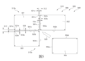
圖 2
繪示如由圖 1
的視野2
所示的該複數個磚片105
中的磚片105ij
的放大圖,其中磚片105ij
可表示被定位到界定顯示設備100
的顯示區域101
的(n
xm
)陣列中的該複數個磚片105
中的一或更多個個別的磚片。標稱磚片200
(用虛線的輪廓線示出)可表示磚片105ij
的標稱的(例如所需、所要的)輪廓。此外,如圖 2
中所繪示且如下文所更完整論述的,在一些實施例中,磚片105ij
的特徵可至少基於用來切割磚片105ij
的技術(包括切割技術的準確度、精確度及容差)而偏離標稱磚片200
的特徵。若切割技術可以可靠地將標稱磚片200
的特徵提供給該複數個磚片105
中的每個磚片,則可在不考慮相對於標稱特徵的偏離的情況下完成將該複數個磚片105
定位到n
xm
陣列中的操作。然而,因為至少用來切割磚片105ij
的技術(包括切割技術的準確度、精確度及容差)在一些實施例中可能提供偏離標稱磚片200
的特徵的磚片105ij
特徵,可在一些實施例中在將該複數個磚片105
組裝到n
xm
陣列中時考慮此類偏離。 FIG. 2 shows an enlarged view of a tile 105ij of the plurality of
例如,在一些實施例中,磚片105ij 可包括預定的參數,包括磚片105ij 的各別側向尺度、磚片105ij 的各別邊緣直度及磚片105ij 的各別方正度中的至少一者。在一些實施例中,預定參數可以基於磚片105ij 的特徵的直接測量結果、磚片105ij 的預定參數的數值分佈及統計上類似的磚片的預定參數的數值分佈中的一或更多者。此外,在一些實施例中,預定參數可以基於相對於標稱值的預定範圍,其中例如可選擇包括在標稱值的六標準差(6-sigma)或三標準差(3-sigma)內的預定參數的一或更多個磚片。For example, in some embodiments, tiles 105ij may include predetermined parameters including at least one of a respective lateral dimension of tile 105ij , a respective edge straightness of tile 105ij , and a respective squareness of tile 105ij . By. In some embodiments, the predetermined parameter may be based on one or more of a direct measurement of a characteristic of the tile 105ij , a distribution of values of the predetermined parameter of the tile 105ij , and a distribution of values of the predetermined parameter of statistically similar tiles. Furthermore, in some embodiments, the predetermined parameter may be based on a predetermined range relative to a nominal value, where, for example, a value within six standard deviations (6-sigma) or three standard deviations (3-sigma) of the nominal value may be selected. One or more tiles of predetermined parameters.
在一些實施例中,磚片105ij
的預定參數的值可包括磚片105ij
的第一邊緣201
與磚片105ij
的相反的第二邊緣202
之間的第一側向尺度D1
(例如平均側向尺度)。同樣地,在一些實施例中,磚片105ij
的預定參數的值可包括磚片105ij
的第三邊緣203
與磚片105ij
的相反的第四邊緣204
之間的第二側向尺度D2
(例如平均側向尺度)。在一些實施例中,磚片105ij
的預定參數的值可包括磚片105ij
的第一邊緣201
的第一直度D5
,該第一直度界定在第一邊緣201
相對於第一側向尺度D1
的最大限度位置201a
與第一邊緣201
相對於第一側向尺度D1
的最小限度位置201b
之間。在一些實施例中,磚片105ij
的預定參數的值可包括磚片105ij
的第二邊緣202
的第二直度D6
,該第二直度界定在第二邊緣202
相對於第一側向尺度D1
的最大限度位置202a
與第二邊緣202
相對於第一側向尺度D1
的最小限度位置202b
之間。在一些實施例中,磚片105ij
的預定參數的值可包括磚片105ij
的第三邊緣203
的第三直度D7
,該第三直度界定在第三邊緣203
相對於第二側向尺度D2
的最大限度位置203a
與第三邊緣203
相對於第二側向尺度D2
的最小限度位置203b
之間。同樣地,在一些實施例中,磚片105ij
的預定參數的值可包括磚片105ij
的第四邊緣204
的第四直度D8
,該第四直度界定在第四邊緣204
相對於第二側向尺度D2
的最大限度位置204a
與第四邊緣204
相對於第二側向尺度D2
的最小限度位置204b
之間。In some embodiments, the value of the predetermined parameter of the tile 105ij may include a first lateral dimension D1 (eg, an average lateral dimension ). Likewise, in some embodiments, the value of the predetermined parameter of the tile 105ij may include a second lateral dimension D2 (eg , average lateral scale). In some embodiments, the value of the predetermined parameter of the tile 105ij may include a first straightness D5 of the
此外,在一些實施例中,磚片105ij
的預定參數的值可包括磚片105ij
的方正度,該方正度被界定為磚片105ij
的第一對角尺度D3
與磚片105ij
的第二對角尺度D4
之間的差異。在一些實施例中,可將第一對角尺度D3
界定為磚片105ij
定位在第一邊緣201
與第三邊緣203
的交接點處的第一轉角205
與磚片105ij
定位在第二邊緣202
與第四邊緣204
的交接點處的第二轉角206
之間的距離。同樣地,在一些實施例中,可將第二對角尺度D4
界定為磚片105ij
定位在第二邊緣202
與第三邊緣203
的交接點處的第三轉角207
與磚片105ij
定位在第一邊緣201
與第四邊緣204
的交接點處的第四轉角208
之間的距離。在一些實施例中,可將方正度參數界定為如何將磚片105ij
的一或更多個轉角與標稱磚片200
的一或更多個各別轉角進行比較的計量單位。例如,在一些實施例中,標稱磚片200
的一或更多個轉角可包括90度的角度(例如矩形),而方正度參數可比較磚片105ij
的一或更多個轉角的各別角度跟90度的角度比較起來如何。此外,在一些實施例中,標稱磚片200
的一或更多個轉角可包括非90度的角度,而方正度參數可比較磚片105ij
的一或更多個轉角的各別角度跟非90度角度比較起來如何。Additionally, in some embodiments, the value of the predetermined parameter of the tile 105ij may include a squareness of the tile 105ij defined as the dimension D3 of the first diagonal of the tile 105ij and the second diagonal of the tile 105ij Difference between scale D4 . In some embodiments, the first diagonal dimension D3 may be defined as the
圖 3
繪示如由圖 2
的視野3
所示的磚片105ij
的一部分的放大圖,該部分包括界定複數個像素305
的複數個微米尺寸的發光二極體(微LED)300
。為了明確起見,圖 3
中並未繪示玻璃或膜401
(參照圖 4
)及基板402
(參照圖 4
)。在一些實施例中,該複數個像素305
中的緊鄰的像素之間的側向距離「px
」及/或「py
」可界定像素間距。在一些實施例中,px
可等於py
,而在一些實施例中,px
可與py
不同。在一些實施例中,像素間距(px
、py
)中的至少一者可以從約50微米到約1000微米,包括其間的所有範圍及子範圍。例如,在一些實施例中,像素間距(px
、py
)中的至少一者可以從約100微米到約200微米、從約100 微米到約300微米、從約100 微米到約400微米、從約100 微米到約500微米、從約500 微米到約600微米、從約600 微米到約700微米、從約700 微米到約800微米、從約800 微米到約900微米、從約900 微米到約1000微米。在一些實施例中,像素間距(px
、py
)中的至少一者可小於50微米(例如從約0微米到約50微米,包括其間的所有範圍及子範圍)或大於1000微米(例如從約1毫米到約3毫米,包括其間的所有範圍及子範圍)。 FIG. 3 shows an enlarged view of a portion of tile 105ij comprising a plurality of micron-sized light emitting diodes (micro LEDs) 300 defining a plurality of
在一些實施例中,標稱磚片200
可包括在從約10 mm到約100 cm的範圍(包括其間的所有範圍及子範圍)內的第一側向尺度D1
及在從約10 mm到約100 cm的範圍(包括其間的所有範圍及子範圍)內的第二側向尺度D2
。在一些實施例中,可基於可採用包括顯示區域的顯示設備的特定應用來選擇第一側向尺度D1
及第二側向尺度D2
。例如,回到圖 2
,在一個示例性的實施例中,如表格 1
中所提供的,標稱磚片200
可包括約100.44 mm的第一側向尺度D1
及約178.56 mm的第二側向尺度D2
。此外,針對標稱磚片,D3
可等於D4
,而方正度(D3
-D4
)可因此等於零。同樣地,針對標稱磚片200
,邊緣直度(D5
、D6
、D7
、D8
)可等於零。
此外,表格 2
針對標稱磚片200
針對所指示的從50微米到500微米的像素間距(其中px
等於py
)提供了每一個磚片的各別的像素數量,該標稱磚片包括約100.44 mm的第一側向尺度D1
及約178.56 mm的第二側向尺度D2
。
並且,回到圖 1
,對於包括約100.44 mm的第一側向尺度D1
及約178.56 mm的第二側向尺度D2
的標稱磚片200
而言,表格 3
針對n
xm
陣列提供了顯示區域101
的標稱(n
)尺度、標稱(m
)尺度及對應的對角尺度。
圖 4
示出該複數個像素350
中沿著圖 3
的線4-4
所截取的像素305xy
的橫截面圖,其中像素305xy
可表示包括該複數個微LED300
的該複數個像素350
中的一或更多個個別像素。在一些實施例中,像素305xy
可包括界定像素305xy
的三個微LED(例如第一微LED405a
、第二微LED405b
、第三微LED405c
)。例如,在一些實施例中,微LED中的一者(例如第一微LED405a
)可包括紅色微LED,微LED中的另一者(例如第二微LED405b
)可包括綠色微LED,而微LED中的另一者(例如第三微LED405c
)可包括藍色微LED。此外,在一些實施例中,第一微LED405a
可包括第一電極403a
以控制第一微LED405a
的操作,第二微LED405b
可包括第二電極403b
以控制第二微LED405b
的操作,而第三微LED405c
可包括第三電極403c
以控制第三微LED405c
的操作。在一些實施例中,像素305xy
可包括額外的構件及元件(例如薄膜電晶體)以供電氣地控制及操作微LED405a
、405b
、405c
。在一些實施例中,每個微LED405a
、405b
、405c
可包括界定發光區域的從約10微米到約200微米(包括其間的所有範圍及子範圍)的尺度。例如,在一些實施例中,每個微LED405a
、405b
、405c
可包括界定發光區域的從約10微米到約20微米、從約10微米到約50 微米、從約50微米到約100 微米、從約100微米到約200微米的尺度。 4 shows a cross-sectional view of a pixel 305xy of the plurality of
並且,在一些實施例中,可將第一微LED405a
、第二微LED405b
、第三微LED405c
、及各別的第一電極403a
、第二電極403b
、及第三電極403c
連接到基板402
。在一些實施例中,可與基板402
相反地將玻璃或膜401
提供為具有微LED405a
、405b
、405c
、及定位在玻璃或膜401
與基板402
之間的電極403a
、403b
、403c
。在一些實施例中,藉由用各別的電極403a
、403b
、403c
控制例如供應到各別的紅色、綠色及藍色微LED405a
、405b
、405c
中的每一者的電流,像素305xy
可基於添加式混色來提供大範圍的可見光色譜。在一些實施例中,像素305xy
可包括用於單色發射的單個微LED,其中可通過色彩轉換來達成色彩顯示。同樣地,在一些實施例中,在不脫離本揭示案的範圍的情況下,像素305xy可包括被提供為多色LED的單個微LED、被提供為具有濾色器的一或更多個藍色或白色LED、或被提供為微尺寸二極體以依據本揭示內容的實施例來發光的其他半導體光源。此外,在一些實施例中,微LED相對於例如標準發光二極體(LED)及液晶顯示器(LCD)而言可提供較低的電力消耗及較高的對比度以及相對於例如有機發光二極體(OLED)而言提供較長的壽命可操作性。Also, in some embodiments, the first micro-LED 405a , the second micro-LED 405b , the third micro-LED 405c , and the respective
回到圖 2 及參照表格 4-23 ,複數個磚片是使用四種不同的切割技術基於表格 1 的標稱尺度來切割的。此外,測量及記錄了每個磚片的對應預定參數(例如D1-D8)。在一些實施例中,可將預定參數的測量值相對於預定參數的標稱值的偏離歸因於每個各別的切割技術的準確度、精確度及容差。此外,在一些實施例中,可採用二或更多種不同的切割技術來切割該複數個磚片中的每個磚片的一或更多個邊緣。Returning to Figure 2 and referring to Table 4-23 , a plurality of tiles were cut based on the nominal dimensions of Table 1 using four different cutting techniques. In addition, the corresponding predetermined parameters (eg D1-D8) of each tile are measured and recorded. In some embodiments, the deviation of the measured value of the predetermined parameter from the nominal value of the predetermined parameter can be attributed to the accuracy, precision and tolerance of each respective cutting technique. Additionally, in some embodiments, two or more different cutting techniques may be used to cut one or more edges of each tile of the plurality of tiles.
例如,採用了使用標準半導體切粒鋸來切割56個磚片的第一切割技術(切割技術1)。表格 4-8
提供了藉由切割技術1來切割的每個磚片的預定參數的測量值及對應次數。在磚片總數與使用切割技術1來切割的56個磚片不同的一些實施例中,要瞭解到,至少基於誤差或差值(discrepancy),可忽略特定的測量結果,其中此類忽略被認為並未變更測量值的統計顯著性。詳細而言,表格 4
提供了用切割技術1來切割的該複數個磚片的第一側向尺度D1
的測量值及該等測量值的對應次數。
表格 5
提供了用切割技術1來切割的該複數個磚片的第二側向尺度D2
的測量值及該等測量值的對應次數。
表格 6
提供了用切割技術1來切割的該複數個磚片的方正度(D3
-D4
)的測量值及該等測量值的對應次數。表格 6 Table 6 provides the measured values of the squareness ( D3 - D4 ) of the plurality of tiles cut by cutting
表格 7
提供了用切割技術1來切割的該複數個磚片相對於第一側向尺度D1
的直度(D5
、D6
)的測量值及該等測量值的對應次數。表格 7 Table 7 provides the measurements of the straightness ( D5 , D6 ) of the plurality of tiles cut with cutting
表格 8
提供了用切割技術1來切割的該複數個磚片相對於第二側向尺度D2
的直度(D7
、D8
)的測量值及該等測量值的對應次數。表格 8 Table 8 provides the measured values of the straightness ( D7 , D8 ) of the plurality of tiles cut with cutting
採用了使用由MDI Advanced Processing公司所製造的MP500精確度機械劃線來切割52個磚片的第二切割技術(切割技術2)。表格 9-13
提供了藉由切割技術2來切割的每個磚片的預定參數的測量值。在磚片總數與使用切割技術2來切割的52個磚片不同的一些實施例中,要瞭解到,至少基於誤差或差值(discrepancy),可忽略特定的測量結果,其中此類忽略被認為並未變更測量值的統計顯著性。詳細而言,表格 9
提供了用切割技術2來切割的該複數個磚片的第一側向尺度D1
的測量值及該等測量值的對應次數。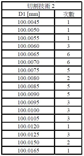
表格 10
提供了用切割技術2來切割的該複數個磚片的第二側向尺度D2
的測量值及該等測量值的對應次數。
表格 11
提供了用切割技術2來切割的該複數個磚片的方正度(D3
-D4
)的測量值及該等測量值的對應次數。表格 11 Table 11 provides the measured values of the squareness ( D3 - D4 ) of the plurality of tiles cut by cutting
表格 12
提供了用切割技術2來切割的該複數個磚片相對於第一側向尺度D1
的直度(D5
、D6
)的測量值及該等測量值的對應次數。表格 12 Table 12 provides the measurements of the straightness ( D5 , D6 ) of the plurality of tiles cut with cutting
表格 13
提供了用切割技術2來切割的該複數個磚片相對於第二側向尺度D2
的直度(D7
、D8
)的測量值及該等測量值的對應次數。
採用了使用非繞射射束CLT雷射切割過程來切割41個磚片的第三切割技術(切割技術3)。表格 14-18
提供了藉由切割技術3來切割的每個磚片的預定參數的測量值。在磚片總數與使用切割技術3來切割的41個磚片不同的一些實施例中,要瞭解到,至少基於誤差或差值(discrepancy),可忽略特定的測量結果,其中此類忽略被認為並未變更測量值的統計顯著性。詳細而言,表格 14
提供了用切割技術3來切割的該複數個磚片的第一側向尺度D1
的測量值及該等測量值的對應次數。
表格 15
提供了用切割技術3來切割的該複數個磚片的第二側向尺度D2
的測量值及該等測量值的對應次數。
表格 16
提供了用切割技術3來切割的該複數個磚片的方正度(D3
-D4
)的測量值及該等測量值的對應次數。表格 16 Table 16 provides the measured values of the squareness ( D3 - D4 ) of the plurality of tiles cut by cutting
表格 17
提供了用切割技術3來切割的該複數個磚片相對於第一側向尺度D1
的直度(D5
、D6
)的測量值及該等測量值的對應次數。表格 17 Table 17 provides the measurements of the straightness ( D5 , D6 ) of the plurality of tiles cut with cutting
表格 18
提供了用切割技術3來切割的該複數個磚片相對於第二側向尺度D2
的直度(D7
、D8
)的測量值及該等測量值的對應次數。
採用了使用TLC International公司的Phoenix牌(例如Gen-3、Gen-5)機械玻璃切割機工具的第四切割技術(切割技術4),該工具採用精確劃線及斷裂過程來切割48個磚片。表格 19-23
提供了藉由切割技術4來切割的每個磚片的預定參數的測量值。在磚片總數與使用切割技術4來切割的48個磚片不同的一些實施例中,要瞭解到,至少基於誤差或差值(discrepancy),可忽略特定的測量結果,其中此類忽略被認為並未變更測量值的統計顯著性。詳細而言,表格 19
提供了用切割技術4來切割的該複數個磚片的第一側向尺度D1
的測量值及該等測量值的對應次數。
表格 20
提供了用切割技術4來切割的該複數個磚片的第二側向尺度D2
的測量值及該等測量值的對應次數。
表格 21
提供了用切割技術4來切割的該複數個磚片的方正度(D3
-D4
)的測量值及該等測量值的對應次數。表格 21 Table 21 provides the measured values of the squareness ( D3 - D4 ) of the plurality of tiles cut by cutting
表格 22
提供了用切割技術4來切割的該複數個磚片相對於第一側向尺度D1
的直度(D5
、D6
)的測量值及該等測量值的對應次數。表格 22 Table 22 provides the measurements of the straightness ( D5 , D6 ) of the plurality of tiles cut with cutting
表格 23
提供了用切割技術4來切割的該複數個磚片相對於第二側向尺度D2
的直度(D7
、D8
)的測量值及該等測量值的對應次數。
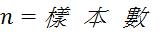
在採用表格 4-23
的測量值的情況下,實施了電腦模擬以隨機產生複數個磚片,其中每個隨機產生的磚片包括統計上表示測量值的預定參數(D1
-D8
)。例如,藉由採用測量值,在不實體切割及生產統計上大量的磚片的情況下,電腦模擬可隨機產生統計上大量的磚片(例如100,000個磚片、250,000個磚片、500,000個磚片、1,000,000個磚片、10,000,000個磚片、100,000,000個磚片等等),該等隨機產生的磚片準確地表示了會由實體切割磚片所生產的統計上大量的磚片的預定參數。在一些實施例中,可將每種切割技術(例如切割技術1-4)的每個預定參數(例如第一側向尺度D1
、第二側向尺度D2
、方正度(D3
–D4
)、D1
直度(D5
、D6
)及D2
直度(D7
、D8
))的測量值與一種統計分佈數值地契合,可從該統計分佈隨機產生統計上大量的磚片的預定參數的值。詳細而言,等式 1
提供了常態(高斯)分佈及相關聯的變數,藉由該常態分佈及相關聯的變數,可基於測量值來決定統計上大量的磚片的預定參數中的一些: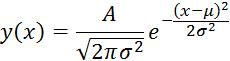


類似地,等式 2
提供了組合的常態(高斯)分佈及相關聯的變數,藉由該組合的常態分佈及相關聯的變數,可基於測量值來決定統計上大量的磚片的預定參數中的一些:


同樣地,等式 3
提供了對數常態分佈及相關聯的變數,藉由該對數常態分佈及相關聯的變數,可基於測量值來決定統計上大量的磚片的預定參數中的一些: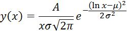


因此,在一些實施例中,取決於資料的分佈,與藉由切割技術1-4中的每一者來切割的磚片的預定參數(D1
-D8
)中的每一者的測量值結合而採用等式 1-3
中的一者,以針對統計上大量的磚片中的每個磚片隨機產生預定參數。例如,表格 24-43
提供了計算過的變數,該等變數是基於表格 4-23
的測量值來決定的且與等式 1-3
中的一者一起結合使用來針對切割技術1-4的統計上大量隨機產生的磚片中的每個磚片計算預定參數。為了計算的目的,假設磚片的所有邊緣具有相同的分佈;然而,在一些實施例中,磚片的一或更多個邊緣可具有不同的分佈且可以是由一或更多種不同的切割技術或邊緣處理技術(例如研磨、拋光)所提供的。詳細而言,對於基於等式 1
來隨機產生的預定參數而言,在示出基於測量值及對應的常態分佈來計算的各別變數及相關聯的變數的表格中列出了用語「(常態)」。同樣地,對於基於等式 2
來隨機產生的預定參數而言,在示出基於測量值及對應的組合常態分佈來計算的各別變數及相關聯的變數的表格中列出了用語「(組合)」。類似地,對於基於等式 3
來隨機產生的預定參數而言,在示出基於測量值及對應的對數常態分佈來計算的各別變數及相關聯的變數的表格中列出了用語「(ln)」。Thus, in some embodiments, depending on the profile of the data, combined with measurements of each of the predetermined parameters ( D1 - D8 ) of the tiles cut by each of the cutting techniques 1-4, One of Equations 1-3 is employed to randomly generate predetermined parameters for each tile in a statistically large number of tiles. For example, Tables 24-43 provide calculated variables that were determined based on the measurements in Table 4-23 and used in conjunction with one of Equations 1-3 for Cutting Techniques 1-4. A predetermined parameter is calculated for each of the statistically large number of randomly generated tiles. For calculation purposes, it is assumed that all edges of a tile have the same distribution; however, in some embodiments, one or more edges of a tile may have a different distribution and may be formed by one or more different cuts. technology or edge treatment techniques (e.g. grinding, polishing) provided. In detail, for predetermined parameters randomly generated based on
詳細而言,表格 24-28
提供了計算過的變數,該等變數分別是基於表格 4-8
的測量值(例如第一側向尺度D1
、第二側向尺度D2
、方正度(D3
–D4
)、D1
直度(D5
、D6
)及D2
直度(D7
、D8
))來決定的且與等式 1-3
(如所標識的)中的一者一起結合使用來針對切割技術1的統計上大量的磚片中的每個磚片隨機產生預定參數。
此外,表格 29-33
提供了計算過的變數,該等變數分別是基於表格 9-13
的測量值(例如第一側向尺度D1
、第二側向尺度D2
、方正度(D3
–D4
)、D1
直度(D5
、D6
)及D2
直度(D7
、D8
))來決定的且與等式 1-3
(如所標識的)中的一者一起結合使用來針對切割技術2的統計上大量的磚片中的每個磚片隨機產生預定參數。
此外,表格 34-38
提供了計算過的變數,該等變數分別是基於表格 14-18
的測量值(例如第一側向尺度D1
、第二側向尺度D2
、方正度(D3
–D4
)、D1
直度(D5
、D6
)及D2
直度(D7
、D8
))來決定的且與等式 1-3
(如所標識的)中的一者一起結合使用來針對切割技術3的統計上大量的磚片中的每個磚片隨機產生預定參數。
此外,表格 39-43
提供了計算過的變數,該等變數分別是基於表格 19-23
的測量值(例如第一側向尺度D1
、第二側向尺度D2
、方正度(D3
–D4
)、D1
直度(D5
、D6
)及D2
直度(D7
、D8
))來決定的且與等式 1-3
(如所標識的)中的一者一起結合使用來針對切割技術4的統計上大量的磚片中的每個磚片隨機產生預定參數。
並且,在一些實施例中,可實施另外的電腦模擬以將包括隨機產生的預定參數D1 -D8 的模擬統計上大量的磚片組裝到各種尺寸的(n xm )陣列中的操作。在一些實施例中,可基於藉由電腦模擬來獲得的資訊用一或更多種策略來採用組裝顯示區域的實際方法。如下文更完整地論述的,在一些實施例中,相對於在不採用該一或更多種策略的情況下可能原本不能達到的將該複數個磚片組裝及定位到陣列中的操作而言,採用該一或更多種策略可提供一或更多個優勢。Also, in some embodiments, additional computer simulations may be performed to assemble a simulated statistically large number of tiles comprising randomly generated predetermined parameters D1 - D8 into arrays of various sizes ( n x m ). In some embodiments, the actual method of assembling the display area may be employed with one or more strategies based on information obtained through computer simulations. As discussed more fully below, in some embodiments, with respect to the operation of assembling and positioning the plurality of tiles into an array that might otherwise not be achievable without employing the one or more strategies , employing the one or more strategies may provide one or more advantages.
例如,在一些實施例中,電腦模擬可模擬將隨機產生的磚片中的每一者組裝到各種陣列中的一者中的操作。在一些實施例中,可基於全域位置法來將每個磚片定位到陣列中,在使用該全域位置法的情況下,磚片的定位基於預定的全域空間坐標而不考慮其他磚片的相對位置。或者,在一些實施例中,可基於相對位置法來將每個磚片定位到陣列中,在使用該相對位置法的情況下,磚片的定位基於緊鄰磚片(亦即彼此緊鄰定位且沒有其他磚片在其間的一或更多個磚片)的相對位置而不考慮磚片的全域空間坐標。並且,在一些實施例中,無論是否與全域位置法或相對位置法一起採用,在模擬期間,若磚片是相對於一或更多個緊鄰的磚片用重疊的關係來定位的,則模擬可選擇性地調整磚片相對於該一或更多個緊鄰磚片的位置,使得磚片相對於該一或更多個緊鄰磚片而言是用非重疊關係定位到陣列中的。For example, in some embodiments, an in silico simulation may simulate the act of assembling each of the randomly generated tiles into one of the various arrays. In some embodiments, each tile can be positioned into the array based on a global position method, where the positioning of the tiles is based on predetermined global space coordinates without regard to the relative position of other tiles. Location. Alternatively, in some embodiments, each tile may be positioned into the array based on a relative position method, in which case the tiles are positioned based on immediately adjacent tiles (i.e., positioned in close proximity to each other and without The relative position of one or more tiles between other tiles) regardless of the global space coordinates of the tiles. Also, in some embodiments, whether used with the global position method or the relative position method, during simulation, if a tile is positioned in an overlapping relationship with respect to one or more immediately adjacent tiles, the simulated The position of the tile relative to the one or more immediately adjacent tiles may be selectively adjusted such that the tile is positioned in the array in a non-overlapping relationship relative to the one or more immediately adjacent tiles.
回到圖 5
,在瞭解到可獨立提供或與顯示區域510
及顯示設備500
的一或更多個特徵一起結合來提供顯示區域101
及顯示設備100
的一或更多個特徵的情況下,現將描述組裝顯示設備500
的顯示區域510
的方法。要瞭解到,可將組裝顯示區域510
的方法採用作電腦模擬及/或採用作組裝要採用在依據本揭示內容的實施例的一或更多個顯示設備500
中的顯示區域510
的實際方法。Returning to FIG. 5 , knowing that one or more features of the
在一些實施例中,該方法可包括以下步驟:在瞭解到複數個磚片505
中的每個磚片501
、502
、503
、504
可包括該複數個磚片105
中的磚片105ij
的一或更多個特徵(包括一或更多個預定參數(參照圖 2
的預定參數D1
-D8
))及界定複數個像素的複數個微LED(參照圖3的複數個像素305
、複數個微LED300
、及圖 5
的微LED405a
、405b
、405c
)的情況下,提供該複數個磚片505
(例如第一磚片501
、第二磚片502
、第三磚片503
及第四磚片504
)。此外,儘管繪示了四個磚片501
、502
、503
、504
,但要瞭解到,在一些實施例中,該複數個磚片505
可包括多於四個的磚片。例如,在一些實施例中,在不脫離本揭示內容的範圍的情況下,該複數個磚片505
可包括要組裝到界定顯示區域510
的5 x 5陣列中的25個磚片、要組裝到界定顯示區域510
的6 x 6陣列中的36個磚片、要組裝到界定顯示區域510
的7 x 7陣列中的49個磚片、要組裝到界定顯示區域510
的8 x 8陣列中的64個磚片、要組裝到界定顯示區域510
的9 x 9陣列中的81個磚片、要組裝到界定顯示區域510
的10 x 10陣列中的100個磚片、或要組裝到n
xm
陣列(參照圖 1
)中的任何其他數量的磚片。在一些實施例中,n
可等於m
(例如5 x 5陣列、6 x 6陣列、7 x 7陣列等等),且在一些實施例中,n
及m
可以是不同的(例如5 x 6陣列、6 x 8陣列、7 x 10陣列等等)。In some embodiments, the method may include the following steps: After knowing that each
回到圖 5
,在一些實施例中,第一磚片501
的與第一磚片501
的第一邊緣501a
隔開的至少一個第一外像素521a
與第二磚片502
的與第二磚片502
的第二邊緣502a
隔開的至少一個第二外像素522a
之間的側向距離512
可界定配準間距512
。同樣地,在一些實施例中,第一磚片501
的與第一磚片501
的第二邊緣501b
隔開的至少一個第一外像素521b
與第三磚片503
的與第三磚片503
的第二邊緣503b
隔開的至少一個第二外像素523b
之間的側向距離513
可界定配準間距513
。在一些實施例中,可基於該至少一個第一外像素521a
相對於第一磚片501
的第一邊緣501a
的第一側向偏位531a
、該至少一個第二外像素522a
相對於第二磚片502
的第二邊緣502a
的第二側向偏位532a
、及第一磚片501
的第一邊緣501a
與第二磚片502
的第二邊緣502a
之間的間隔(例如間隙534
),來界定配準間距512
。同樣地,在一些實施例中,可基於該至少一個第一外像素521b
相對於第一磚片501
的第二邊緣501b
的第一側向偏位531b
、該至少一個第二外像素523b
相對於第三磚片503
的第二邊緣503b
的第二側向偏位533b
、及第一磚片501
的第二邊緣501b
與第三磚片503
的第二邊緣503b
之間的間隔(例如間隙535
),來界定配準間距513
。在一些實施例中,可將側向偏位531a
、532a
、531b
及533b
界定為從各別外像素的中心到磚片的切割邊緣的最近位置的各別距離,該等側向偏位被選擇為使得切割邊緣不干擾各別的外像素的電子操作。並且,在將額外的磚片組裝到陣列中時,可在額外磚片的緊鄰磚片的緊鄰外像素之間界定各別的配準間距。Returning to FIG. 5 , in some embodiments, at least one first
在一些實施例中,可將間隙534
、535
選擇為防止磚片501
、502
、503
的緊鄰邊緣(邊緣501a
與邊緣502a
、邊緣501b
與邊緣503b
)之間的接觸。在一些實施例中,防止磚片501
、502
、503
的緊鄰邊緣之間的接觸可防止緊鄰邊緣的切屑、破裂、斷裂及其他損傷,若該等緊鄰邊緣是要接觸的,則該等損傷原本可能是會發生的。例如,在一些實施例中,間隙534
、535
可以從約5微米到約200微米,包括其間的所有範圍及子範圍。例如,在一些實施例中,間隙534
、535
可以從約5微米到約50微米、從約50微米到約100微米、從約100微米到約200微米。並且,在一些實施例中,間隙534
、535
可基於預定參數(例如第一側向尺度D1
、第二側向尺度D2
、方正度(D3
–D4
)、D1
直度(D5
、D6
)及D2
直度(D7
、D8
))的至少一個值相對於標稱磚片200
(參照圖 2
)的對應值的偏離,沿著磚片501
、502
、503
的各別的緊鄰邊緣(邊緣501a
及邊緣502a
、邊緣501b
及邊緣503b
)而變化。In some embodiments,
在一些實施例中,可在每個磚片501
、502
、503
上提供側向偏位531a
、532a
、531b
、533b ,
使得包括相關聯的電子設備(例如薄膜電晶體、佈線)及微LED的該至少一個外像素521a
、522a
、521b
、523b
與磚片501
、502
、503
的各別邊緣501a
、502a
、501b
、503b
分隔一定距離,以例如保護微LED免於電氣或機械損傷,若包括相關聯的電子設備及微LED的該至少一個外像素521a
、522a
、521b
、523b
與磚片501
、502
、503
的各別邊緣501a
、502a
、501b
、503b
齊平,則該電氣或機械損傷可能原本會發生。在一些實施例中,側向偏位531a
、532a
、531b
、533b
可以是在從約0.02 mm到約0.6 mm的範圍中,包括其間的所有範圍及子範圍。例如,在一些實施例中,側向偏位531a
、532a
、531b
、533b
可以從約0.02 mm到約0.05 mm、從約0.05 mm到約0.1 mm、從約0.1 mm到約0.2 mm、從約0.2 mm到約0.3 mm、從約0.3 mm到約0.4 mm、從約0.4 mm到約0.5 mm、從約0.5 mm到約0.6 mm。In some embodiments, a lateral offset 531a , 532a , 531b , 533b can be provided on each
在一些實施例中,針對組裝到界定顯示設備的顯示區域的陣列中的所有緊鄰磚片界定預定的配準間距可提供一個準則,在該準則下,例如可將等於或小於預定配準間距的配準間距視為可接受的,而可將大於預定配準間距的配準間距視為不可接受的。在一些實施例中,可接受的配準間距可與一個視覺上均勻、無縫的顯示區域對應,在該顯示區域處,組裝到陣列中的所有緊鄰的個別磚片的邊界及之間的邊界對於檢視界定顯示區域的該複數個像素的人眼來說在視覺上不是可辨別的。或者,在一些實施例中,不可接受的配準間距可與一個顯示區域對應,在該顯示區域處,組裝到陣列中的一或更多個緊鄰的個別磚片的邊界及之間的邊界對於檢視界定顯示區域的該複數個像素的人眼來說在視覺上是可辨別的。In some embodiments, defining a predetermined registration spacing for all immediately adjacent tiles assembled into an array bounding a display area of a display device may provide a criterion under which, for example, tiles equal to or smaller than the predetermined registration spacing may be Registration distances are considered acceptable, while registration distances greater than a predetermined registration distance may be considered unacceptable. In some embodiments, acceptable registration spacing may correspond to a visually uniform, seamless display area where the boundaries between and between all immediately adjacent individual tiles assembled into the array It is not visually discernible to the human eye viewing the plurality of pixels defining the display area. Alternatively, in some embodiments, an unacceptable registration spacing may correspond to a display area where the boundaries between and between one or more immediately adjacent individual tiles assembled into an array are relatively It is visually discernible to the human eye viewing the plurality of pixels defining the display area.
例如,在一些實施例中,可將不可接受的顯示區域陣列界定為包括緊鄰磚片的一或更多個緊鄰外像素的陣列,該一或更多個緊鄰外像素隔開大於預定配準間距的側向距離。同樣地,在一些實施例中,可將可接受的顯示區域陣列界定為一個陣列,在該陣列處,緊鄰磚片的所有緊鄰外像素隔開小於或等於預定配準間距的側向距離。在一些實施例中,可將失敗(例如在模擬將磚片組裝到陣列中的操作的電腦模擬期間)界定為不可接受的顯示區域的模擬事件。同樣地,在一些實施例中,可將失敗率(例如在模擬將磚片組裝到陣列中的操作的電腦模擬期間)界定為不可接受的顯示區域的模擬事件相對於可接受的顯示區域的模擬事件的比率。例如,在一些實施例中,針對模擬將磚片組裝到陣列中的操作的電腦模擬,100%的失敗率可與所有模擬的陣列都包括不可接受的顯示區域的模擬對應,而0%的失敗率可與所有模擬的陣列都包括可接受的顯示區域的模擬對應。For example, in some embodiments, an array of unacceptable display areas may be defined as an array comprising one or more immediately outer pixels of a tile that are separated by more than a predetermined registration pitch the lateral distance. Likewise, in some embodiments, an acceptable display area array may be defined as an array at which all immediately outer pixels of an adjacent tile are separated by a lateral distance less than or equal to a predetermined registration pitch. In some embodiments, a failure (eg, during an in silico simulation simulating the operation of assembling tiles into an array) may be defined as a simulated event of an unacceptable display area. Likewise, in some embodiments, a failure rate (such as during an in silico simulation simulating the operation of assembling tiles into an array) may be defined as a simulation of simulated events of unacceptable display area versus acceptable display area rate of events. For example, in some embodiments, for an in silico simulation simulating the operation of assembling tiles into an array, a 100% failure rate may correspond to a simulation in which all simulated arrays include unacceptable display areas, while a 0% failure rate The rate may correspond to a simulation in which all simulated arrays include an acceptable display area.
在一些實施例中,配準間距512
、513
可小於或等於像素間距(參照圖 3
的像素間距px
、py
)的約1.5倍。此外,在一些實施例中,配準間距512
、513
可小於或等於像素間距px
、py
的約1.4倍、小於或等於像素間距px
、py
的約1.3倍、小於或等於像素間距px
、py
的約1.25倍、小於或等於像素間距px
、py
的約1.2倍、或小於或等於像素間距px
、py
的約1.1倍。並且,在一些實施例中,配準間距512
、513
可小於或等於像素間距px
、py
的約1.01倍、或小於或等於像素間距px
、py
。在一些實施例中,配準間距512
可與配準間距513
不同。同樣地,在一些實施例中,配準間距512
可基於像素間距px
及像素間距py
中的至少一者,而配準間距513
可基於像素間距px
及像素間距py
中的至少一者。在一些實施例中,配準間距512
可相對於配準間距513
呈相同或不同比例地基於像素間距px
、py
中的至少一者。在一些實施例中,可基於一或更多個額外因素來選擇配準間距512
、513
,包括但不限於採用顯示區域的應用。在一些實施例中,基於像素間距px
、py
來界定配準間距512
、513
可提供人眼看起來像是均勻、無縫的像素陣列的對應顯示區域,該像素陣列提供了要採用在依據本揭示內容的實施例的一或更多個顯示設備中的高品質、視覺上優美的顯像。In some embodiments, the
針對圖 6 、圖 7 、表格 44 及表格 45 ,採用了示例性電腦模擬以比較切割技術1-4之間的差異。詳細而言,電腦模擬模擬了將包括隨機產生的預定參數D1 -D8 值的統計上大量的磚片組裝到界定多個各別的顯示陣列的多個陣列中的操作。在電腦模擬中,採用了相對位置法,其中針對大於對應的像素間距px 、py 1.1倍的配準間距界定了失敗準則。For Figures 6 , 7 , Table 44 , and Table 45 , exemplary computer simulations were used to compare the differences between cutting techniques 1-4. In detail, computer simulations simulated the operation of assembling a statistically large number of tiles comprising randomly generated values of predetermined parameters D1 - D8 into a plurality of arrays defining a plurality of respective display arrays. In computer simulations, a relative position method was used, in which a failure criterion was defined for a registration spacing greater than 1.1 times the corresponding pixel spacing px , py .
圖 6
繪示依據本揭示內容的實施例的針對每種切割技術1-4的基於包括具有50微米的側向偏位的複數個磚片的顯示區域的模擬組裝的示例性圖表,其中垂直或「Y」軸用百分比(%)表示失敗率,而水平或「X」軸用微米(µm)表示像素間距。此外,表格 44
針範圍從50微米到500微米的對像素間距相對於所界定的失敗準則針對每種切割技術1-4提供了圖 6
中所示的圖表所依據的資料,其中線601a
表示切割技術1的相關聯的失敗率,線602a
表示切割技術2的相關聯的失敗率,線603a
表示切割技術3的相關聯的失敗率,而線604a
表示切割技術4的相關聯的失敗率。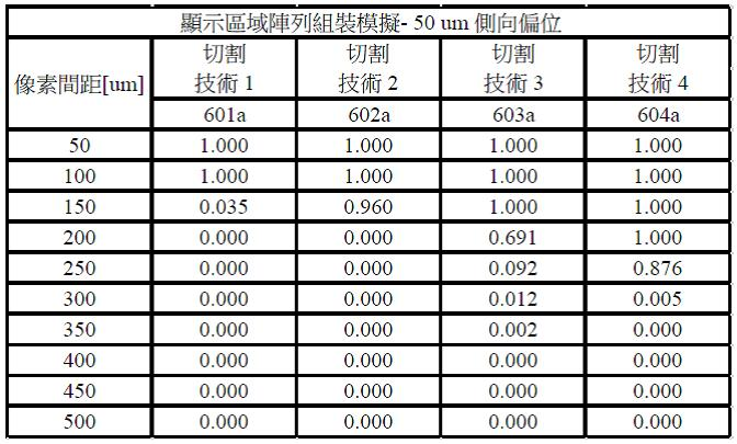
如從圖 6
及表格 44
可見的,基於電腦模擬,在一些實施例中,藉由採用切割技術1,可針對包括具有約150微米或更大的像素間距的複數個陣列化磚片的顯示區域達成約10%或更少的失敗率。同樣地,藉由採用切割技術2,可針對包括具有約200微米或更大的像素間距的複數個陣列化磚片的顯示區域達成約10%或更少的失敗率,藉由採用切割技術3,可針對包括具有約250微米或更大的像素間距的複數個陣列化磚片的顯示區域達成約10%或更少的失敗率,及藉由採用切割技術4,可針對包括具有約300微米或更大的像素間距的複數個陣列化磚片的顯示區域達成約10%或更少的失敗率。As can be seen from FIG. 6 and Table 44 , based on computer simulations, in some embodiments, by employing
圖 7
繪示依據本揭示內容的實施例的針對每種切割技術1-4的基於包括具有100微米的側向偏位的複數個磚片的顯示區域的模擬組裝的示例性圖表,其中垂直或「Y」軸用百分比(%)表示失敗率,而水平或「X」軸用微米(µm)表示像素間距。此外,表格 45
針範圍從50微米到500微米的對像素間距相對於所界定的失敗準則針對每種切割技術1-4提供了圖 7
中所示的圖表所依據的資料,其中線601b
表示切割技術1的相關聯的失敗率,線602b
表示切割技術2的相關聯的失敗率,線603b
表示切割技術3的相關聯的失敗率,而線604b
表示切割技術4的相關聯的失敗率。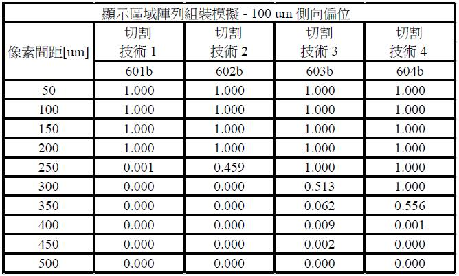
如從圖 7
及表格 45
可見的,基於電腦模擬,在一些實施例中,藉由採用切割技術1,可針對包括具有約250微米或更大的像素間距的複數個陣列化磚片的顯示區域達成約10%或更少的失敗率。同樣地,藉由採用切割技術2,可針對包括具有約300微米或更大的像素間距的複數個陣列化磚片的顯示區域達成約10%或更少的失敗率,藉由採用切割技術3,可針對包括具有約350微米或更大的像素間距的複數個陣列化磚片的顯示區域達成約10%或更少的失敗率,及藉由採用切割技術4,可針對包括具有約400微米或更大的像素間距的複數個陣列化磚片的顯示區域達成約10%或更少的失敗率。As can be seen from FIG. 7 and Table 45 , based on computer simulations, in some embodiments, by employing
因此,基於圖 6
及圖 7
中所示的電腦模擬的結果,吾人可基於可接受的失敗率及預定的像素間距來選擇特定的切割技術(例如切割技術1-4)以切割該複數個磚片。在一些實施例中,可在選擇要採用的切割技術時考慮切割技術的各別成本及將該成本充當因素。例如,在一些實施例中,可選擇切割技術1來切割要在高品質的顯示區域(例如行動顯示器、電視顯示器)中採用的磚片;而可選擇切割技術4來切割要在相對較低品質的顯示區域(例如戶外標誌)中採用的磚片。在一些實施例中,相對於例如切割技術4而言,採用切割技術1可以是相對更昂貴的及/或耗時的 因此,可藉由基於從圖 6
及圖 7
中所提供的電腦模擬所獲得的資訊來選擇切割技術1-4中的一者來獲得相當大的優勢。Therefore, based on the results of computer simulations shown in FIGS. 6 and 7 , one can select a specific cutting technique (such as cutting techniques 1-4) to cut the plurality of bricks based on an acceptable failure rate and a predetermined pixel pitch piece. In some embodiments, the individual cost of the dicing technique may be considered and factored into the selection of the dicing technique to employ. For example, in some embodiments, cutting
並且,如針對圖 8-11
及表格 46-57
所描述的,針對與切割技術3對應的統計上大量的磚片基於隨機產生的預定參數D1
-D8
值採用了另外的電腦模擬,其中對於50微米及100微米的側向偏位(參照圖 5
的側向偏位531a
、532a
、531b
、533b
)而言,預定的像素間距(px
、py
)為372微米,其中px
等於py
。模擬磚片中的每一者(包括隨機產生的預定參數D1
-D8
值)是採用全域定位法及相對定位法來組裝到複數個(n
xm
)陣列中的。此外,模擬了像素間距的1.5倍、像素間距的1.1倍及像素間距的1.01倍的配準間距。針對每個模擬情境重複1,000,000次模擬,以提供可從以形成代表性趨勢及結論的統計樣本。並且,要瞭解到,考慮到圖 6
、圖 7
、表格 44
及表格 45
中所提供的比較資料,基於切割技術3的電腦模擬(圖 8-11
及表格 46-57
)所觀察到的趨勢相對於切割技術1、切割技術2及切割技術4而言可提供同等相關的結論。And, as described with respect to FIGS. 8-11 and Tables 46-57 , additional computer simulations were employed based on randomly generated predetermined parameter D1 - D8 values for a statistically large number of tiles corresponding to cutting
此外,模擬了三種不同的鋪磚策略,且記錄了顯示區域的各別失敗率。第一鋪磚策略可包括以下步驟:隨機選擇要組裝到陣列中的每個磚片。例如,在一些實施例中,針對第一鋪磚策略,電腦模擬在不考慮隨機產生的預定參數D1 -D8 值的情況下隨機選擇包括隨機產生的預定參數D1 -D8 值的每個磚片,及依據本揭示內容的實施例將磚片組裝到各種陣列中。Furthermore, three different tiling strategies were simulated and the respective failure rates of the displayed areas were recorded. The first tiling strategy may include the step of randomly selecting each tile to be assembled into the array. For example, in some embodiments, for the first tiling strategy, computer simulations randomly select each tile comprising a randomly generated value for the predetermined parameter D1 - D8 without regard to the value of the randomly generated predetermined parameter D1 - D8 , and assemble tiles into various arrays according to embodiments of the present disclosure.
表格 46
提供了針對採用全域定位法的50微米側向偏位磚片採用第一鋪磚策略的電腦模擬的失敗率,該全域定位法將磚片定位到5 x 5陣列、6 x 6陣列、7 x 7陣列、8 x 8陣列、9 x 9陣列及10 x 10陣列中,其中配準間距為像素間距的1.5倍、為像素間距的1.1倍及為像素間距的1.01倍。
此外,圖 8
基於表格 46
的第一鋪磚策略的模擬組裝來繪示示例性圖表,其中垂直或「Y」軸用百分比(%)表示失敗率,而水平或「X」軸用陣列(n x m)中的磚片數量表示顯示區域尺寸。詳細而言,線701a
針對用採用第一鋪磚策略的全域定位法組裝的50微米偏位磚片針對為像素間距的1.1倍的配準間距表示各種陣列的各別失敗率,而線701b
針對用採用第一鋪磚策略的全域定位法組裝的50微米偏位磚片針對為像素間距的1.01倍的配準間距表示各種陣列的各別失敗率。Additionally, FIG. 8 depicts an exemplary graph based on a simulated assembly of the first tiling strategy of Table 46 , wherein the vertical or "Y" axis represents failure rate in percent (%) and the horizontal or "X" axis in array (nxm The number of tiles in ) indicates the size of the display area. In detail,
表格 47
提供了針對採用相對定位法的50微米側向偏位磚片採用第一鋪磚策略的電腦模擬的失敗率,該相對定位法將磚片定位到5 x 5陣列、6 x 6陣列、7 x 7陣列、8 x 8陣列、9 x 9陣列及10 x 10陣列中,其中配準間距為像素間距的1.5倍、為像素間距的1.1倍及為像素間距的1.01倍。
此外,圖 9
基於表格 47
的第一鋪磚策略的模擬組裝來繪示示例性圖表,其中垂直或「Y」軸用百分比(%)表示失敗率,而水平或「X」軸用陣列(n x m)中的磚片數量表示顯示區域尺寸。詳細而言,線701c
針對用採用第一鋪磚策略的相對定位法組裝的50微米偏位磚片針對為像素間距的1.1倍的配準間距表示各種陣列的各別失敗率,而線701d
針對用採用第一鋪磚策略的相對定位法組裝的50微米偏位磚片針對為像素間距的1.01倍的配準間距表示各種陣列的各別失敗率。Additionally, FIG. 9 depicts an exemplary graph based on a simulated assembly of the first tiling strategy of Table 47 , wherein the vertical or "Y" axis represents failure rate in percent (%) and the horizontal or "X" axis in array (nxm The number of tiles in ) indicates the size of the display area. In detail,
表格 48 提供了針對採用全域定位法的100微米側向偏位磚片採用第一鋪磚策略的電腦模擬的失敗率,該全域定位法將磚片定位到5 x 5陣列、6 x 6陣列、7 x 7陣列、8 x 8陣列、9 x 9陣列及10 x 10陣列中,其中配準間距為像素間距的1.5倍、為像素間距的1.1倍及為像素間距的1.01倍。表格 48 Table 48 provides computer simulated failure rates for the first tiling strategy for 100 micron laterally offset tiles using global positioning to position tiles in 5 x 5 arrays, 6 x 6 arrays, In 7 x 7 arrays, 8 x 8 arrays, 9 x 9 arrays and 10 x 10 arrays, the registration pitch is 1.5 times the pixel pitch, 1.1 times the pixel pitch, and 1.01 times the pixel pitch. Form 48
此外,圖 10
基於表格 48
的第一鋪磚策略的模擬組裝來繪示示例性圖表,其中垂直或「Y」軸用百分比(%)表示失敗率,而水平或「X」軸用陣列(n x m)中的磚片數量表示顯示區域尺寸。詳細而言,線704a
針對用採用第一鋪磚策略的全域定位法組裝的100微米偏位磚片針對為像素間距的1.1倍的配準間距表示各種陣列的各別失敗率,而線704b
針對用採用第一鋪磚策略的全域定位法組裝的100微米偏位磚片針對為像素間距的1.01倍的配準間距表示各種陣列的各別失敗率。Additionally, FIG. 10 depicts an exemplary graph based on a simulated assembly of the first tiling strategy of Table 48 , wherein the vertical or "Y" axis represents failure rate in percent (%) and the horizontal or "X" axis in array (nxm The number of tiles in ) indicates the size of the display area. In detail,
表格 49
提供了針對採用相對定位法的100微米側向偏位磚片採用第一鋪磚策略的電腦模擬的失敗率,該相對定位法將磚片定位到5 x 5陣列、6 x 6陣列、7 x 7陣列、8 x 8陣列、9 x 9陣列及10 x 10陣列中,其中配準間距為像素間距的1.5倍、為像素間距的1.1倍及為像素間距的1.01倍。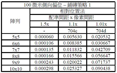
此外,圖 11
基於表格 49
的第一鋪磚策略的模擬組裝來繪示示例性圖表,其中垂直或「Y」軸用百分比(%)表示失敗率,而水平或「X」軸用陣列(n x m)中的磚片數量表示顯示區域尺寸。詳細而言,線704c
針對用採用第一鋪磚策略的相對定位法組裝的100微米偏位磚片針對為像素間距的1.1倍的配準間距表示各種陣列的各別失敗率,而線704d
針對用採用第一鋪磚策略的相對定位法組裝的100微米偏位磚片針對為像素間距的1.01倍的配準間距表示各種陣列的各別失敗率。Additionally, FIG. 11 depicts an exemplary graph based on a simulated assembly of the first tiling strategy of Table 49 , wherein the vertical or "Y" axis represents failure rate in percent (%) and the horizontal or "X" axis in array (nxm The number of tiles in ) indicates the size of the display area. In detail,
第二鋪磚策略可包括以下步驟:選擇要組裝到陣列的外周邊中的特定磚片及選擇要組裝到陣列的內部中的其他磚片。例如,在一些實施例中,針對第二鋪磚策略,電腦模擬依據本揭示內容的實施例選擇具有界定相對於各別標稱值的第一偏離的隨機產生的預定參數D1 -D8 值的複數個磚片及圍繞各種陣列的外周邊而定位彼等磚片。此外,在一些實施例中,針對第二鋪磚策略,電腦模擬依據本揭示內容的實施例選擇具有界定相對於各別標稱值的第二偏離的隨機產生的預定參數D1 -D8 值的複數個磚片及將彼等磚片定位在各種陣列的內部中。在一些實施例中,外磚片的第一偏離大於內磚片的第二偏離。The second tiling strategy may include the steps of selecting specific tiles to be assembled into the outer perimeter of the array and selecting other tiles to be assembled into the interior of the array. For example, in some embodiments, for the second tiling strategy, in silico selects a complex of randomly generated predetermined parameter D1 - D8 values defining a first deviation from the respective nominal values in accordance with embodiments of the present disclosure. tiles and position those tiles around the outer perimeter of the various arrays. Furthermore, in some embodiments, for a second tiling strategy, computer simulations select complex values having randomly generated predetermined parameter D1 - D8 values defining second deviations from respective nominal values in accordance with embodiments of the present disclosure. tiles and position those tiles in the interior of the various arrays. In some embodiments, the first offset of the outer tile is greater than the second offset of the inner tile.
表格 50
提供了針對採用全域定位法的50微米側向偏位磚片採用第二鋪磚策略的電腦模擬的失敗率,該全域定位法將磚片定位到5 x 5陣列、6 x 6陣列、7 x 7陣列、8 x 8陣列、9 x 9陣列及10 x 10陣列中,其中配準間距為像素間距的1.5倍、為像素間距的1.1倍及為像素間距的1.01倍。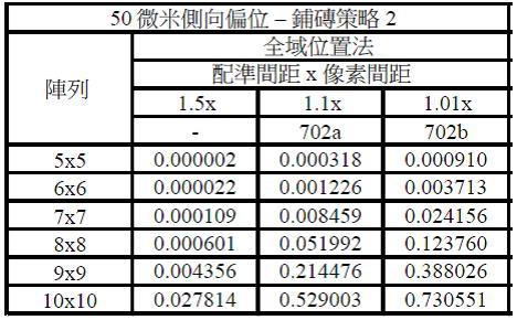
此外,圖 8
基於表格 50
的第二鋪磚策略的模擬組裝繪示了示例性圖表。詳細而言,線702a
針對用採用第二鋪磚策略的全域定位法組裝的50微米偏位磚片針對為像素間距的1.1倍的配準間距表示各種陣列的各別失敗率,而線702b
針對用採用第二鋪磚策略的全域定位法組裝的50微米偏位磚片針對為像素間距的1.01倍的配準間距表示各種陣列的各別失敗率。Additionally, FIG. 8 depicts an exemplary diagram based on simulated assembly of the second tiling strategy of Table 50 . In detail,
表格 51
提供了針對採用相對定位法的50微米側向偏位磚片採用第二鋪磚策略的電腦模擬的失敗率,該相對定位法將磚片定位到5 x 5陣列、6 x 6陣列、7 x 7陣列、8 x 8陣列、9 x 9陣列及10 x 10陣列中,其中配準間距為像素間距的1.5倍、為像素間距的1.1倍及為像素間距的1.01倍。
此外,圖 9
基於表格 51
的第二鋪磚策略的模擬組裝繪示了示例性圖表。詳細而言,線702c
針對用採用第二鋪磚策略的相對定位法組裝的50微米偏位磚片針對為像素間距的1.1倍的配準間距表示各種陣列的各別失敗率,而線702d
針對用採用第二鋪磚策略的相對定位法組裝的50微米偏位磚片針對為像素間距的1.01倍的配準間距表示各種陣列的各別失敗率。In addition, FIG. 9 depicts an exemplary diagram based on the simulated assembly of the second tiling strategy of Table 51 . In detail,
表格 52
提供了針對採用全域定位法的100微米側向偏位磚片採用第二鋪磚策略的電腦模擬的失敗率,該全域定位法將磚片定位到5 x 5陣列、6 x 6陣列、7 x 7陣列、8 x 8陣列、9 x 9陣列及10 x 10陣列中,其中配準間距為像素間距的1.5倍、為像素間距的1.1倍及為像素間距的1.01倍。
此外,圖 10
基於表格 52
的第二鋪磚策略的模擬組裝繪示了示例性圖表。詳細而言,線705a
針對用採用第二鋪磚策略的全域定位法組裝的100微米偏位磚片針對為像素間距的1.1倍的配準間距表示各種陣列的各別失敗率,而線705b
針對用採用第二鋪磚策略的全域定位法組裝的100微米偏位磚片針對為像素間距的1.01倍的配準間距表示各種陣列的各別失敗率。In addition, FIG. 10 depicts an exemplary graph based on the simulated assembly of the second tiling strategy of Table 52 . In detail,
表格 53
提供了針對採用相對定位法的100微米側向偏位磚片採用第二鋪磚策略的電腦模擬的失敗率,該相對定位法將磚片定位到5 x 5陣列、6 x 6陣列、7 x 7陣列、8 x 8陣列、9 x 9陣列及10 x 10陣列中,其中配準間距為像素間距的1.5倍、為像素間距的1.1倍及為像素間距的1.01倍。
此外,圖 11
基於表格 53
的第二鋪磚策略的模擬組裝繪示了示例性圖表。詳細而言,線705c
針對用採用第二鋪磚策略的相對定位法組裝的100微米偏位磚片針對為像素間距的1.1倍的配準間距表示各種陣列的各別失敗率,而線705d
針對用採用第二鋪磚策略的相對定位法組裝的100微米偏位磚片針對為像素間距的1.01倍的配準間距表示各種陣列的各別失敗率。In addition, FIG. 11 depicts an exemplary diagram based on the simulated assembly of the second tiling strategy of Table 53 . In detail,
針對第二鋪磚策略,是假設相對於第一鋪磚策略,可藉由採用第二鋪磚策略來減少顯示區域的失敗率。然而,如圖 8-11
中所提供的,可看見的是,相對於第一鋪磚策略(例如線701a
、701b
、701c
、701d
,及線704a
、704b
、704c
、704d
),第二鋪磚策略的各別失敗率(例如線702a
、702b
、702c
、702d
,及線705a
、705b
、705c
、705d
)增加了。因此,在一些實施例中,第二鋪磚策略相較於第一鋪磚策略可能產生較高的失敗率。For the second tiling strategy, it is assumed that compared with the first tiling strategy, the failure rate of the display area can be reduced by adopting the second tiling strategy. However, as provided in Figures 8-11 , it can be seen that relative to the first tiling strategy (eg,
回到圖 5
,第三鋪磚策略可包括以下步驟:基於該複數個磚片505
中的第一磚片501
的預定參數D1
-D8
的值來選擇第一磚片501
,及基於該複數個磚片505
中的第二磚片502
的預定參數D1
-D8
的值來選擇第二磚片502
。在一些實施例中,該方法可包括以下步驟:將第一磚片501
及第二磚片502
定位到界定顯示區域510
的至少一部分的陣列506
中。在一些實施例中,第一磚片501
的第一邊緣501a
可面向第二磚片502
的第二邊緣502a
。Returning to Fig. 5 , the third tiling strategy may include the steps of: selecting the
在一些實施例中,第一磚片501
的預定參數D1
-D8
的值可大於預定參數D1
-D8
的標稱值,而第二磚片502
的預定參數D1
-D8
的值可小於預定參數D1
-D8
的標稱值。在一些實施例中,第一磚片501
的預定參數D1
-D8
的值可相對於預定參數D1
-D8
的標稱值界定該複數個磚片505
的預定參數D1
-D8
的最大值,而第二磚片502
的預定參數D1
-D8
的值可相對於預定參數D1
-D8
的標稱值界定該複數個磚片505
的預定參數D1
-D8
的最小值。In some embodiments, the values of the predetermined parameters D1 - D8 of the
例如,在一些實施例中,藉由選擇具有大於預定參數D1
-D8
的標稱值的預定參數D1
-D8
值的第一磚片501
及具有小於預定參數D1
-D8
的標稱值的預定參數D1
-D8
值的第二磚片502
,第一磚片501
及第二磚片502
相對於標稱磚片的各別偏離可彼此補償(例如抵消)。因此,在一些實施例中,所假設的是,藉由基於預定參數D1
-D8
的值來選擇磚片及用磚片相對於標稱磚片的偏離可彼此抵消的方式來組裝磚片,會獲得對應顯示器的失敗率的減少。For example, in some embodiments, by selecting a
在一些實施例中,該方法可更包括以下步驟:基於該複數個磚片505
的各別的預定參數D1
-D8
值來分類該複數個磚片505
。在一些實施例中,該分類步驟可包括以下步驟:識別第一組磚片及第二組磚片。同樣地,在一些實施例中,該分類步驟可包括以下步驟:基於該複數個磚片505
的各別的預定參數D1
-D8
值來識別複數組磚片(例如多於兩組磚片)。在一些實施例中,第一組磚片中的每個磚片的各別的預定參數D1
-D8
值可大於預定參數D1
-D8
的標稱值,而第二組磚片中的每個磚片的各別的預定參數D1
-D8
值可小於預定參數D1
-D8
的標稱值。在一些實施例中,該方法可更包括以下步驟:基於第一組磚片中的每個磚片的各別的預定參數D1
-D8
值,來用遞升次序或遞降次序來排序第一組磚片,及基於第二組磚片中的每個磚片的各別的預定參數D1
-D8
值,來用遞升次序或遞降次序排序第二組磚片。在一些實施例中,可從第一組磚片選擇第一磚片501
,且可從第二組磚片選擇第二磚片502
。In some embodiments, the method may further include the step of: sorting the plurality of
在一些實施例中,第一磚片501
的預定參數D1
-D8
的值可相對於預定參數D1
-D8
的標稱值界定第一組磚片的預定參數D1
-D8
的最大值,而第二磚片502
的預定參數D1
-D8
的值可相對於預定參數D1
-D8
的標稱值界定第二組磚片的預定參數D1
-D8
的最小值。In some embodiments, the values of the predetermined parameters D1 - D8 of the
在一些實施例中,該方法可更包括以下步驟:基於該複數個磚片505
中的至少一個額外磚片(例如第三磚片503
、第四磚片504
)的預定參數D1
-D8
值,來選擇該至少一個額外磚片503
、504
,及將該至少一個額外磚片503
、504
定位到陣列506
中。例如,在一些實施例中,可將第三磚片503
定位到陣列506
中,其中第三磚片503
的第二邊緣503b
面向第一磚片501
的第二邊緣501b
。同樣地,如由箭頭525
所表示的,在一些實施例中,可將第四磚片504
定位到陣列506
中,其中第四磚片504
的第一邊緣504a
面向第三磚片503
的第一邊緣503a
,而第四磚片504
的第二邊緣504b
面向第二磚片502
的第二邊緣502b
。在一些實施例中,可藉由基於該複數個磚片505
中的至少一個額外磚片的預定參數D1
-D8
的值來選擇該至少一個額外磚片及將該至少一個額外磚片定位到陣列506
中,來重複該方法複數次,直到顯示區域510
包括預定數量的磚片為止。In some embodiments, the method may further comprise the step of: based on the predetermined parameter D1 - D8 values of at least one additional tile (eg
附加性或替代性地,在一些實施例中,組裝顯示區域510
的該方法可包括以下步驟:基於每個磚片的各別的預定參數D1
-D8
值來選擇複數對磚片。在一些實施例中,每對磚片可包括第一磚片及第二磚片。例如,第一對磚片515a
可包括第一磚片501
及第二磚片502
,而第二對磚片515b
可包括第三磚片503
及第四磚片504
。在一些實施例中,每對515a
、515b
中的第一磚片(例如磚片501
、磚片503
)的各別的預定參數D1
-D8
值可大於每對515a
、515b
中的第二磚片(例如磚片502
、磚片504
)的各別的預定參數D1
-D8
值。該方法可更包括以下步驟:將該複數對磚片515a
、515b
定位到界定顯示區域510
的至少一部分的陣列506
中。在一些實施例中,每對515a
、515b
中的第一磚片(例如磚片501
、磚片503
)的各別的第一邊緣501a
、503a
可面向每對515a
、515b中的第二磚片(例如磚片502
、磚片504
)的各別的第二邊緣502a
、504a
。Additionally or alternatively, in some embodiments, the method of assembling
在一些實施例中,每對515a
、515b
中的第一磚片(例如磚片501
、磚片503
)的各別的預定參數D1
-D8
值可大於預定參數D1
-D8
的標稱值,而每對515a
、515b
中的第二磚片(例如磚片502
、磚片504
)的各別的預定參數D1
-D8
值可小於預定參數D1
-D8
的標稱值。In some embodiments, the respective predetermined parameters D1 - D8 values of the first tiles in each
在一些實施例中,該方法可更包括以下步驟:識別第一組磚片及第二組磚片。第一組磚片中的每個磚片的各別的預定參數D1
-D8
值可大於預定參數D1
-D8
的標稱值,而第二組磚片中的每個磚片的各別的預定參數D1
-D8
值可小於預定參數D1
-D8
的標稱值。在一些實施例中,可從第一組磚片選擇每對磚片515a
、515b
中的第一磚片(例如磚片501
、磚片503
),且可從第二組磚片選擇每對磚片515a
、515b
中的第二磚片(例如磚片502
、磚片504
)。In some embodiments, the method may further include the step of: identifying the first set of tiles and the second set of tiles. The respective predetermined parameter D1 - D8 values of each tile in the first group of tiles may be greater than the nominal value of the predetermined parameters D1 - D8 , while the respective predetermined parameters of each tile in the second group of tiles The values of the parameters D1 - D8 may be less than the nominal values of the predetermined parameters D1 - D8 . In some embodiments, the first tile in each pair of
在一些實施例中,該方法可更包括以下步驟:基於第一組磚片中的每個磚片的各別的預定參數D1
-D8
值,來用遞升次序或遞降次序來排序第一組磚片,及基於第二組磚片中的每個磚片的各別的預定參數D1
-D8
值,來用遞升次序或遞降次序排序第二組磚片。可依序從第一組排序過的磚片選擇每對磚片515a
、515b
中的第一磚片(例如磚片501
、磚片503
),且可依序從第二組排序過的磚片選擇每對磚片515a
、515b
中的第二磚片(例如磚片502
、磚片504
)。In some embodiments, the method may further comprise the step of sorting the first set of tiles in ascending order or descending order based on the respective predetermined parameter D1 - D8 values of each tile in the first set of tiles slices, and sort the second set of tiles in ascending order or descending order based on the respective predetermined parameter D1 - D8 values of each tile in the second set of tiles. The first tile in each pair of
電腦模擬是藉由依據本揭示內容的方法基於預定參數D2 的值依據第三鋪磚策略選擇磚片來執行的。例如,磚片是基於各別的預定參數D2 值來選擇的,其中磚片相對於標稱磚片的偏離可彼此抵消。同樣地,在一些實施例中,可基於各別的二或更多個預定參數D1 -D8 值來選擇一或更多個磚片,其中該一或更多個磚片的該二或更多個預定參數D1 -D8 相對於標稱磚片的偏離可彼此抵消。The computer simulation is performed by selecting tiles according to the method according to the present disclosure according to the third tiling strategy based on the value of the predetermined parameter D2 . For example, the tiles are selected based on respective values of predetermined parameters D2 , wherein the deviations of the tiles from the nominal tile can cancel each other out. Likewise, in some embodiments, one or more tiles may be selected based on respective values of two or more predetermined parameters D1 - D8 , wherein the two or more Deviations of the predetermined parameters D1 - D8 relative to the nominal tile can cancel each other out.
表格 54
提供了針對採用全域定位法的50微米側向偏位磚片採用第三鋪磚策略的電腦模擬的失敗率,該全域定位法將磚片定位到5 x 5陣列、6 x 6陣列、7 x 7陣列、8 x 8陣列、9 x 9陣列及10 x 10陣列中,其中配準間距為像素間距的1.5倍、為像素間距的1.1倍及為像素間距的1.01倍。
此外,圖 8
基於表格 54
的第三鋪磚策略的模擬組裝繪示了示例性圖表。詳細而言,線703a
針對用採用第三鋪磚策略的全域定位法組裝的50微米偏位磚片針對為像素間距的1.1倍的配準間距表示各種陣列的各別失敗率,而線703b
針對用採用第三鋪磚策略的全域定位法組裝的50微米偏位磚片針對為像素間距的1.01倍的配準間距表示各種陣列的各別失敗率。In addition, FIG. 8 depicts an exemplary graph based on simulated assembly of the third tiling strategy of Table 54 . In detail,
表格 55
提供了針對採用相對定位法的50微米側向偏位磚片採用第一鋪磚策略的電腦模擬的失敗率,該相對定位法將磚片定位到5 x 5陣列、6 x 6陣列、7 x 7陣列、8 x 8陣列、9 x 9陣列及10 x 10陣列中,其中配準間距為像素間距的1.5倍、為像素間距的1.1倍及為像素間距的1.01倍。
此外,圖 9
基於表格 55
的第三鋪磚策略的模擬組裝繪示了示例性圖表。詳細而言,線703c
針對用採用第三鋪磚策略的相對定位法組裝的50微米偏位磚片針對為像素間距的1.1倍的配準間距表示各種陣列的各別失敗率,而線703d
針對用採用第三鋪磚策略的相對定位法組裝的50微米偏位磚片針對為像素間距的1.01倍的配準間距表示各種陣列的各別失敗率。In addition, FIG. 9 depicts an exemplary diagram based on the simulated assembly of the third tiling strategy of Table 55 . In detail,
表格 56
提供了針對採用全域定位法的100微米側向偏位磚片採用第三鋪磚策略的電腦模擬的失敗率,該全域定位法將磚片定位到5 x 5陣列、6 x 6陣列、7 x 7陣列、8 x 8陣列、9 x 9陣列及10 x 10陣列中,其中配準間距為像素間距的1.5倍、為像素間距的1.1倍及為像素間距的1.01倍。
此外,圖 10
基於表格 56
的第三鋪磚策略的模擬組裝繪示了示例性圖表。詳細而言,線706a
針對用採用第三鋪磚策略的全域定位法組裝的100微米偏位磚片針對為像素間距的1.1倍的配準間距表示各種陣列的各別失敗率,而線706b
針對用採用第三鋪磚策略的全域定位法組裝的100微米偏位磚片針對為像素間距的1.01倍的配準間距表示各種陣列的各別失敗率。Additionally, FIG. 10 depicts an exemplary graph based on a simulated assembly of the third tiling strategy of Table 56 . In detail,
表格 57 提供了針對採用相對定位法的100微米側向偏位磚片採用第一鋪磚策略的電腦模擬的失敗率,該相對定位法將磚片定位到5 x 5陣列、6 x 6陣列、7 x 7陣列、8 x 8陣列、9 x 9陣列及10 x 10陣列中,其中配準間距為像素間距的1.5倍、為像素間距的1.1倍及為像素間距的1.01倍。表格 57 Table 57 provides computer simulated failure rates for the first tiling strategy for 100 micron laterally offset tiles using the relative positioning method for positioning tiles in 5 x 5 arrays, 6 x 6 arrays, In 7 x 7 arrays, 8 x 8 arrays, 9 x 9 arrays and 10 x 10 arrays, the registration pitch is 1.5 times the pixel pitch, 1.1 times the pixel pitch, and 1.01 times the pixel pitch. Form 57
此外,圖 11
基於表格 57
的第三鋪磚策略的模擬組裝繪示了示例性圖表。詳細而言,線706c
針對用採用第三鋪磚策略的相對定位法組裝的100微米偏位磚片針對為像素間距的1.1倍的配準間距表示各種陣列的各別失敗率,而線706d
針對用採用第三鋪磚策略的相對定位法組裝的100微米偏位磚片針對為像素間距的1.01倍的配準間距表示各種陣列的各別失敗率。In addition, FIG. 11 depicts an exemplary diagram based on the simulated assembly of the third tiling strategy of Table 57 . In detail,
針對第三鋪磚策略,如所述,是假設相對於第一鋪磚策略,可藉由採用第三鋪磚策略來減少顯示區域的失敗率。此外,可採用第三鋪磚策略以將複數個磚片定位在整個顯示區域上以及將複數個磚片定位在顯示區域的一或更多個預定區域(例如周邊、轉角、中心區域)中。如圖 8-11
中所提供的,可看見的是,相對於第一鋪磚策略(例如線701a
、701b
、701c
、701d
,及線704a
、704b
、704c
、704d
),第三鋪磚策略的各別失敗率(例如線703a
、703b
、703c
、703d
,及線706a
、706b
、706c
、706d
)減少了。因此,在一些實施例中,第三鋪磚策略相較於第一鋪磚策略可產生較低的失敗率。因此,在一些實施例中,依據本揭示內容的實施例來組裝包括複數個磚片的顯示區域在減少顯示設備的顯示區域的失敗率的方面可提供數個優勢,該複數個磚片包括界定複數個像素的複數個微LED。For the third tiling strategy, as mentioned, it is assumed that the failure rate of the display area can be reduced by adopting the third tiling strategy compared to the first tiling strategy. Additionally, a third tiling strategy may be employed to position the tiles across the entire display area and in one or more predetermined areas (eg, perimeter, corners, central areas) of the display area. As provided in Figures 8-11 , it can be seen that relative to the first tiling strategy (eg,
並且,在一些實施例中,第一、第二或第三鋪磚策略中的一或更多者的示例性變體可包括以下步驟:藉由例如從該複數個磚片移除不在預定參數D1 -D8 的值的數值分佈的預定標準差(例如六標準差、三標準差)內的一或更多個磚片,來更改(例如截去)該複數個磚片。因此,在一些實施例中,在移除該一或更多個磚片之後,在不脫離本揭示內容的範圍的情況下,可依據第一、第二或第三鋪磚策略中的一或更多者從更改過的該複數個磚片選擇磚片。同樣地,在一些實施例中,基於預定參數D1 -D8 的值來選擇磚片的操作可以基於單個預定參數、或一或更多個預定參數D1 -D8 的組合。Also, in some embodiments, an exemplary variation of one or more of the first, second, or third tiling strategy may include the step of removing a predetermined parameter by, for example, removing from the plurality of tiles One or more tiles within a predetermined standard deviation (such as six standard deviations, three standard deviations) of the numerical distribution of the values of D1 - D8 , to change (for example, truncate) the plurality of tiles. Thus, in some embodiments, after removal of the one or more tiles, one or more of the first, second or third tiling strategies may be used without departing from the scope of the present disclosure. Furthermore, a tile is selected from the changed plurality of tiles. Likewise, in some embodiments, selecting tiles based on the values of the predetermined parameters D1 - D8 may be based on a single predetermined parameter, or a combination of one or more predetermined parameters D1 - D8 .
應瞭解到,儘管已針對各種實施例的某些說明性及具體的實施例詳細描述了該等實施例,但不應將本揭示內容視為受限於此,因為在不脫離以下請求項的範圍的情況下,所揭露的特徵的許多更改及組合是可能的。It should be appreciated that while the various embodiments have been described in detail with respect to certain illustrative and specific embodiments, the disclosure should not be considered so limited since, without departing from the claims below Many modifications and combinations of the disclosed features are possible within the given scope.
100‧‧‧顯示設備 101‧‧‧顯示區域 105‧‧‧磚片 105ij‧‧‧磚片 200‧‧‧標稱磚片 201‧‧‧第一邊緣 201a‧‧‧最大限度位置 201b‧‧‧最小限度位置 202‧‧‧第二邊緣 202a‧‧‧最大限度位置 202b‧‧‧最小限度位置 203‧‧‧第三邊緣 203a‧‧‧最大限度位置 203b‧‧‧最小限度位置 204‧‧‧第四邊緣 204a‧‧‧最大限度位置 204b‧‧‧最小限度位置 205‧‧‧第一轉角 206‧‧‧第二轉角 207‧‧‧第三轉角 208‧‧‧第四轉角 300‧‧‧微LED 305‧‧‧像素 305xy‧‧‧像素 401‧‧‧玻璃或膜 402‧‧‧基板 403a‧‧‧像素間距 403b‧‧‧第二電極 403c‧‧‧第三電極 405a‧‧‧第一微LED 405b‧‧‧第二微LED 405c‧‧‧第三微LED 500‧‧‧顯示設備 501‧‧‧第一磚片 501a‧‧‧第一邊緣 501b‧‧‧第二邊緣 502‧‧‧第二磚片 502a‧‧‧第二邊緣 502b‧‧‧第二邊緣 503‧‧‧第三磚片 503a‧‧‧第一邊緣 503b‧‧‧第二邊緣 504‧‧‧第四磚片 504a‧‧‧第一邊緣 504b‧‧‧第二邊緣 505‧‧‧磚片 506‧‧‧陣列 510‧‧‧顯示區域 512‧‧‧配準間距 513‧‧‧配準間距 515a‧‧‧第一對磚片 515b‧‧‧第二對磚片 521a‧‧‧外像素 521b‧‧‧外像素 522a‧‧‧外像素 523b‧‧‧外像素 525‧‧‧箭頭 531a‧‧‧側向偏位 531b‧‧‧側向偏位 532a‧‧‧側向偏位 533b‧‧‧側向偏位 534‧‧‧間隙 535‧‧‧間隙 601a‧‧‧線 601b‧‧‧線 602a‧‧‧線 602b‧‧‧線 603a‧‧‧線 603b‧‧‧線 604a‧‧‧線 604b‧‧‧線 701a‧‧‧線 701b‧‧‧線 701c‧‧‧線 701d‧‧‧線 702a‧‧‧線 702b‧‧‧線 702c‧‧‧線 702d‧‧‧線 703a‧‧‧線 703b‧‧‧線 703c‧‧‧線 703d‧‧‧線 704a‧‧‧線 704b‧‧‧線 704c‧‧‧線 704d‧‧‧線 705a‧‧‧線 705b‧‧‧線 705c‧‧‧線 705d‧‧‧線 706a‧‧‧線 706b‧‧‧線 706c‧‧‧線 706d‧‧‧線 D1‧‧‧第一側向尺度 D2‧‧‧第二側向尺度 D3‧‧‧第一對角尺度 D4‧‧‧第二對角尺度 D5‧‧‧第一直度 D6‧‧‧第二直度 D7‧‧‧第三直度 D8‧‧‧第四直度 px‧‧‧像素間距 py‧‧‧像素間距100‧‧‧display equipment 101‧‧‧display area 105‧‧‧Bricks 105ij‧‧‧Bricks 200‧‧‧nominal tiles 201‧‧‧First Edge 201a‧‧‧maximum position 201b‧‧‧minimum position 202‧‧‧Second Edge 202a‧‧‧maximum position 202b‧‧‧minimum position 203‧‧‧The third edge 203a‧‧‧maximum position 203b‧‧‧minimum position 204‧‧‧The fourth edge 204a‧‧‧maximum position 204b‧‧‧minimum position 205‧‧‧First corner 206‧‧‧The second corner 207‧‧‧The third corner 208‧‧‧4th corner 300‧‧‧micro LED 305‧‧‧pixels 305xy‧‧‧pixels 401‧‧‧Glass or film 402‧‧‧substrate 403a‧‧‧Pixel pitch 403b‧‧‧Second electrode 403c‧‧‧The third electrode 405a‧‧‧The first micro LED 405b‧‧‧The second micro LED 405c‧‧‧The third micro LED 500‧‧‧display equipment 501‧‧‧The first brick 501a‧‧‧First Edge 501b‧‧‧Second Edge 502‧‧‧The second brick 502a‧‧‧Second Edge 502b‧‧‧Second Edge 503‧‧‧The third brick 503a‧‧‧First Edge 503b‧‧‧Second Edge 504‧‧‧4th brick 504a‧‧‧First Edge 504b‧‧‧Second Edge 505‧‧‧Bricks 506‧‧‧array 510‧‧‧display area 512‧‧‧Registration distance 513‧‧‧Registration distance 515a‧‧‧The first pair of bricks 515b‧‧‧The second pair of bricks 521a‧‧‧outside pixels 521b‧‧‧outside pixels 522a‧‧‧outside pixels 523b‧‧‧outside pixels 525‧‧‧arrow 531a‧‧‧lateral deviation 531b‧‧‧lateral deviation 532a‧‧‧lateral deviation 533b‧‧‧lateral deviation 534‧‧‧Gap 535‧‧‧Gap 601a‧‧‧Line 601b‧‧‧Line 602a‧‧‧Line 602b‧‧‧Line 603a‧‧‧Line 603b‧‧‧Line 604a‧‧‧Line 604b‧‧‧Line 701a‧‧‧Line 701b‧‧‧Line 701c‧‧‧Line 701d‧‧‧Line 702a‧‧‧Line 702b‧‧‧Line 702c‧‧‧Line 702d‧‧‧Line 703a‧‧‧Line 703b‧‧‧Line 703c‧‧‧Line 703d‧‧‧Line 704a‧‧‧Line 704b‧‧‧Line 704c‧‧‧Line 704d‧‧‧Line 705a‧‧‧Line 705b‧‧‧Line 705c‧‧‧Line 705d‧‧‧Line 706a‧‧‧Line 706b‧‧‧Line 706c‧‧‧Line 706d‧‧‧Line D1‧‧‧first lateral dimension D2‧‧‧Second Lateral Dimension D3‧‧‧First Diagonal Scale D4‧‧‧Second Diagonal Scale D5‧‧‧first straightness D6‧‧‧Second straightness D7‧‧‧Third Straightness D8‧‧‧4th straightness px‧‧‧pixel pitch py‧‧‧pixel pitch
在參照附圖閱讀以下的詳細說明時,會更佳地瞭解該等及其他的特徵、實施例及優點,在該等附圖中:These and other features, embodiments and advantages will be better understood when read with the following detailed description when read with reference to the accompanying drawings, in which:
圖 1 繪示依據本揭示內容的實施例的包括顯示區域的顯示設備的示例性實施例的示意圖,該顯示區域包括複數個磚片; 1 is a schematic diagram of an exemplary embodiment of a display device including a display area including a plurality of tiles according to an embodiment of the present disclosure;
圖 2
繪示依據本揭示內容的實施例的如由圖 1
的視野2
所示的顯示區域的該複數個磚片中的一個磚片的放大圖; FIG. 2 illustrates an enlarged view of one of the plurality of tiles of the display area as shown by field of
圖 3
繪示依據本揭示內容的實施例的如由圖 2
的視野3
所示的磚片的一部分的放大圖,該部分包括界定複數個像素的複數個微LED; 3 illustrates an enlarged view of a portion of a tile including a plurality of micro LEDs defining a plurality of pixels, as shown by field of
圖 4 示出依據本揭示內容的實施例的該複數個像素中的一個像素的沿著圖 3 的線4-4 截取的橫截面圖,該像素包括該複數個微LED中的至少一個微LED; 4 illustrates a cross-sectional view of a pixel of the plurality of pixels including at least one micro-LED of the plurality of micro-LEDs taken along line 4-4 of FIG. 3 in accordance with an embodiment of the disclosure ;
圖 5 繪示依據本揭示內容的實施例的組裝顯示區域的示例性方法; FIG. 5 illustrates an exemplary method of assembling a display area according to an embodiment of the present disclosure;
圖 6 繪示依據本揭示內容的實施例的針對不同的磚片切割技術的基於顯示區域的模擬組裝的示例性圖表,該顯示區域包括複數個50微米偏位的磚片,其中垂直或「Y」軸用百分比(%)表示失敗率,而水平或「X」軸用微米(µm)表示像素間距; 6 depicts an exemplary graph of simulated assembly based on a display area comprising a plurality of 50 micron offset tiles where the vertical or "Y" for different tile cutting techniques according to an embodiment of the disclosure. ” axis represents failure rate in percent (%), while the horizontal or “X” axis represents pixel pitch in microns (µm);
圖 7 繪示依據本揭示內容的實施例的針對不同的磚片切割技術的基於顯示區域的模擬組裝的示例性圖表,該顯示區域包括複數個100微米偏位的磚片,其中垂直或「Y」軸用百分比(%)表示失敗率,而水平或「X」軸用微米(µm)表示像素間距; 7 depicts an exemplary graph of simulated assembly based on a display area comprising a plurality of 100 micron offset tiles where the vertical or "Y" for different tile cutting techniques according to an embodiment of the present disclosure. ” axis represents failure rate in percent (%), while the horizontal or “X” axis represents pixel pitch in microns (µm);
圖 8 繪示示例性圖表,該圖表基於依據本揭示內容的實施例的針對不同配準間距及定位策略使用全域定位容差的包括複數個50微米偏位的磚片的顯示區域的模擬組裝,其中垂直或「Y」軸用百分比(%)表示失敗率,而水平或「X」軸用陣列(n x m)中的磚片數量表示顯示區域尺寸; 8 depicts exemplary graphs based on a simulated assembly of a display area comprising a plurality of 50 micron offset tiles using global positioning tolerances for different registration pitches and positioning strategies in accordance with embodiments of the present disclosure, Where the vertical or "Y" axis represents the failure rate in percentage (%), while the horizontal or "X" axis represents the display area size with the number of tiles in the array (nxm);
圖 9 繪示示例性圖表,該圖表基於依據本揭示內容的實施例的針對不同配準間距及定位策略使用相對定位容差的包括複數個50微米偏位的磚片的顯示區域的模擬組裝,其中垂直或「Y」軸用百分比(%)表示失敗率,而水平或「X」軸用陣列(n x m)中的磚片數量表示顯示區域尺寸; 9 depicts an exemplary graph based on a simulated assembly of a display area comprising a plurality of 50 micron offset tiles using relative positioning tolerances for different registration pitches and positioning strategies in accordance with an embodiment of the present disclosure, The vertical or "Y" axis represents the failure rate in percentage (%), while the horizontal or "X" axis represents the display area size with the number of tiles in the array (nxm);
圖 10 繪示示例性圖表,該圖表基於依據本揭示內容的實施例的針對不同配準間距及定位策略使用相對定位容差的包括複數個100微米偏位的磚片的顯示區域的模擬組裝,其中垂直或「Y」軸用百分比(%)表示失敗率,而水平或「X」軸用陣列(n x m)中的磚片數量表示顯示區域尺寸;及 10 depicts exemplary graphs based on simulated assembly of a display area comprising a plurality of 100 micron offset tiles using relative positioning tolerances for different registration pitches and positioning strategies in accordance with embodiments of the present disclosure, where the vertical or "Y" axis represents the failure rate in percent (%), and the horizontal or "X" axis represents the display area size in terms of the number of tiles in the array (nxm); and
圖 11 繪示示例性圖表,該圖表基於依據本揭示內容的實施例的針對不同配準間距及定位策略使用相對定位容差的包括複數個100微米偏位的磚片的顯示區域的模擬組裝,其中垂直或「Y」軸用百分比(%)表示失敗率,而水平或「X」軸用陣列(n x m)中的磚片數量表示顯示區域尺寸。 11 depicts an exemplary graph based on a simulated assembly of a display area comprising a plurality of 100 micron offset tiles using relative positioning tolerances for different registration pitches and positioning strategies in accordance with embodiments of the present disclosure, Where the vertical or "Y" axis represents the failure rate in percent (%), while the horizontal or "X" axis represents the display area size in terms of the number of tiles in the array (nxm).
國內寄存資訊 (請依寄存機構、日期、號碼順序註記) 無Domestic deposit information (please note in order of depositor, date, and number) none
國外寄存資訊 (請依寄存國家、機構、日期、號碼順序註記) 無Overseas storage information (please note in order of storage country, organization, date, and number) none
100‧‧‧顯示設備 100‧‧‧display equipment
101‧‧‧顯示區域 101‧‧‧display area
105‧‧‧磚片 105‧‧‧Bricks
105ij‧‧‧磚片 105ij‧‧‧Bricks
Claims (10)
Applications Claiming Priority (2)
| Application Number | Priority Date | Filing Date | Title |
|---|---|---|---|
| US201762583020P | 2017-11-08 | 2017-11-08 | |
| US62/583,020 | 2017-11-08 |
Publications (2)
| Publication Number | Publication Date |
|---|---|
| TW201924041A TW201924041A (en) | 2019-06-16 |
| TWI781241B true TWI781241B (en) | 2022-10-21 |
Family
ID=66438600
Family Applications (1)
| Application Number | Title | Priority Date | Filing Date |
|---|---|---|---|
| TW107138272A TWI781241B (en) | 2017-11-08 | 2018-10-30 | Apparatus and methods for assembling a display area |
Country Status (6)
| Country | Link |
|---|---|
| US (3) | US11374053B2 (en) |
| JP (1) | JP7474695B2 (en) |
| KR (1) | KR102651535B1 (en) |
| CN (1) | CN111480232B (en) |
| TW (1) | TWI781241B (en) |
| WO (1) | WO2019094344A1 (en) |
Families Citing this family (5)
| Publication number | Priority date | Publication date | Assignee | Title |
|---|---|---|---|---|
| JP6875643B2 (en) * | 2016-07-01 | 2021-05-26 | 株式会社ソシオネクスト | Semiconductor integrated circuit equipment |
| KR20220036444A (en) * | 2020-09-15 | 2022-03-23 | 삼성디스플레이 주식회사 | Tiling display device |
| JP7546474B2 (en) * | 2020-12-22 | 2024-09-06 | 日本放送協会 | Multi-Display |
| US12237316B2 (en) | 2021-06-25 | 2025-02-25 | Boe Technology Group Co., Ltd. | Display substrate, tiled display panel and display device |
| US12424600B1 (en) | 2022-11-07 | 2025-09-23 | Meta Platforms Technologies, Llc | Tiled display system for field of view expansion |
Citations (4)
| Publication number | Priority date | Publication date | Assignee | Title |
|---|---|---|---|---|
| US20050140569A1 (en) * | 2001-03-28 | 2005-06-30 | Sundahl Robert C. | Displays with multiple tiled display elements |
| TW200538834A (en) * | 2004-02-24 | 2005-12-01 | Eastman Kodak Co | Method for manufacturing a tiled display and tiled display comprising faceplate |
| US20150379182A1 (en) * | 2006-10-07 | 2015-12-31 | Active-Semi, Inc. | Method and System for the Modular Design and Layout of Integrated Circuits |
| US20160365026A1 (en) * | 2015-06-09 | 2016-12-15 | X-Celeprint Limited | Distributed charge-pump power-supply system |
Family Cites Families (49)
| Publication number | Priority date | Publication date | Assignee | Title |
|---|---|---|---|---|
| US5198054A (en) | 1991-08-12 | 1993-03-30 | Xerox Corporation | Method of making compensated collinear reading or writing bar arrays assembled from subunits |
| US5889568A (en) * | 1995-12-12 | 1999-03-30 | Rainbow Displays Inc. | Tiled flat panel displays |
| US5903328A (en) * | 1997-06-16 | 1999-05-11 | Rainbow Displays, Inc. | Tiled flat-panel display with tile edges cut at an angle and tiles vertically shifted |
| US6897855B1 (en) * | 1998-02-17 | 2005-05-24 | Sarnoff Corporation | Tiled electronic display structure |
| JP4009923B2 (en) | 1999-09-30 | 2007-11-21 | セイコーエプソン株式会社 | EL panel |
| US6614171B2 (en) * | 2001-01-10 | 2003-09-02 | Eastman Kodak Company | Light-producing display having spaced apart tiles |
| US6853411B2 (en) | 2001-02-20 | 2005-02-08 | Eastman Kodak Company | Light-producing high aperture ratio display having aligned tiles |
| US6509941B2 (en) | 2001-03-22 | 2003-01-21 | Eastman Kodak Company | Light-producing display having high aperture ratio pixels |
| JP4182661B2 (en) * | 2001-10-31 | 2008-11-19 | ソニー株式会社 | Image display device and manufacturing method thereof |
| JP3870807B2 (en) * | 2001-12-20 | 2007-01-24 | ソニー株式会社 | Image display device and manufacturing method thereof |
| JP4082400B2 (en) | 2004-02-19 | 2008-04-30 | セイコーエプソン株式会社 | Electro-optical device manufacturing method, electro-optical device, and electronic apparatus |
| KR101157425B1 (en) | 2004-12-23 | 2012-06-22 | 엘지디스플레이 주식회사 | Large size display device of tiled method |
| KR101217554B1 (en) | 2006-05-09 | 2013-01-02 | 삼성전자주식회사 | seamless foldable display device |
| US8223087B2 (en) | 2006-09-25 | 2012-07-17 | Samsung Electronics Co., Ltd. | Multi-display apparatus and method of manufacturing the same |
| WO2008126250A1 (en) | 2007-03-30 | 2008-10-23 | Pioneer Corporation | Light emitting device |
| JP2008281662A (en) * | 2007-05-09 | 2008-11-20 | Tanimoto Jitsugyo Kk | Big screen display panel and panel unit used for the same |
| US9013367B2 (en) * | 2008-01-04 | 2015-04-21 | Nanolumens Acquisition Inc. | Flexible display |
| US8537302B2 (en) * | 2008-06-11 | 2013-09-17 | Manufacturing Resources International, Inc. | Liquid crystal display assembly comprising an LED backlight assembly and a movable element placed behind the LED backlight assembly having a hinge to allow access to a rear portion of the LED backlight assembly |
| CN101673009B (en) | 2008-09-12 | 2011-01-26 | 欧睿控股股份有限公司 | Seamlessly joined display and manufacturing method thereof |
| KR101018784B1 (en) | 2008-11-10 | 2011-03-03 | 주식회사 토비스 | Liquid crystal display device comprising a plurality of liquid crystal display module |
| WO2011093713A2 (en) | 2010-01-29 | 2011-08-04 | Nederlandse Organisatie Voor Toegepast-Natuurwetenschappelijk Onderzoek Tno | Assembly, component for an assembly and method of manufacturing an assembly |
| KR101127960B1 (en) * | 2010-02-12 | 2012-03-23 | 디스플레이솔루션스(주) | Large screen display device using a tiling technology and a fabricating method thereof |
| US8917231B2 (en) * | 2010-12-17 | 2014-12-23 | Atmel Corporation | Regulation of gamma characteristic in a display |
| US8823841B2 (en) | 2012-06-20 | 2014-09-02 | Omnivision Technologies, Inc. | Method and apparatus for correcting for vignetting in an imaging system |
| CN103515410B (en) | 2012-06-29 | 2016-08-03 | 乐金显示有限公司 | Organic light-emitting display device and manufacture method thereof |
| JP5993648B2 (en) * | 2012-07-26 | 2016-09-14 | シャープ株式会社 | Method for determining position of display device |
| CN102832230B (en) * | 2012-09-11 | 2015-09-02 | 广东威创视讯科技股份有限公司 | A kind of OLED display module and the OLED mosaic display screen with this OLED display module |
| CN103907190B (en) | 2012-10-16 | 2017-05-17 | 深圳市柔宇科技有限公司 | A kind of OLED splicing display screen and its manufacturing method |
| WO2014174773A1 (en) | 2013-04-25 | 2014-10-30 | パナソニック株式会社 | Passive-matrix display and tiling display |
| JP2015092529A (en) * | 2013-10-01 | 2015-05-14 | ソニー株式会社 | Light-emitting device, light-emitting unit, display device, electronic apparatus, and light-emitting element |
| JP2015184542A (en) * | 2014-03-25 | 2015-10-22 | ソニー株式会社 | Display panel, and method of manufacturing display panel |
| JP2015197544A (en) * | 2014-03-31 | 2015-11-09 | ソニー株式会社 | Mounting board and electronic equipment |
| CN113035850B (en) | 2014-06-18 | 2022-12-06 | 艾克斯展示公司技术有限公司 | Micro-assembly LED display |
| GB201413578D0 (en) * | 2014-07-31 | 2014-09-17 | Infiniled Ltd | A colour iled display on silicon |
| US9772655B1 (en) * | 2014-08-25 | 2017-09-26 | Anthem Displays, Llc | LED module housing |
| US9799719B2 (en) * | 2014-09-25 | 2017-10-24 | X-Celeprint Limited | Active-matrix touchscreen |
| WO2016115040A1 (en) * | 2015-01-12 | 2016-07-21 | Dolby Laboratories Licensing Corporation | Pixel tile structures and layouts |
| KR102377794B1 (en) * | 2015-07-06 | 2022-03-23 | 엘지전자 주식회사 | Display device using semiconductor light emitting device and method for manufacturing |
| US10483253B1 (en) * | 2015-09-24 | 2019-11-19 | Apple Inc. | Display with embedded pixel driver chips |
| JP2017125952A (en) * | 2016-01-14 | 2017-07-20 | Necディスプレイソリューションズ株式会社 | Display position determination device, liquid crystal display device, remote controller, and display position determination method |
| JP2019533184A (en) * | 2016-08-22 | 2019-11-14 | コーニング インコーポレイテッド | Laser welding sealed display module and modular display |
| CN111983850B (en) * | 2016-11-02 | 2023-11-07 | 群创光电股份有限公司 | display device |
| US10459289B2 (en) * | 2016-11-02 | 2019-10-29 | Innolux Corporation | Display device |
| TWI788380B (en) * | 2017-07-11 | 2023-01-01 | 美商康寧公司 | Tiled displays and methods of manufacturing the same |
| US10546913B2 (en) * | 2017-08-01 | 2020-01-28 | Innolux Corporation | Tile display devices and display devices |
| CN111108469B (en) * | 2017-09-20 | 2024-07-12 | 图像影院国际有限公司 | Illuminated display with tiles and data processing |
| US10909914B2 (en) * | 2017-10-12 | 2021-02-02 | Innolux Corporation | Display device and driving method thereof having a display area in a peripheral region |
| TWI790297B (en) * | 2017-10-16 | 2023-01-21 | 美商康寧公司 | Bezel-free display tile with edge-wrapped conductors and methods of manufacture |
| CN111697111B (en) * | 2019-03-13 | 2026-01-20 | 晶元光电股份有限公司 | Fabrication methods for light-emitting elements and systems and devices utilizing them |
-
2018
- 2018-10-30 TW TW107138272A patent/TWI781241B/en active
- 2018-11-06 CN CN201880080784.XA patent/CN111480232B/en active Active
- 2018-11-06 US US16/761,085 patent/US11374053B2/en active Active
- 2018-11-06 KR KR1020207016336A patent/KR102651535B1/en active Active
- 2018-11-06 JP JP2020525853A patent/JP7474695B2/en active Active
- 2018-11-06 WO PCT/US2018/059300 patent/WO2019094344A1/en not_active Ceased
-
2022
- 2022-05-23 US US17/750,852 patent/US11881501B2/en active Active
-
2023
- 2023-11-29 US US18/522,502 patent/US12100729B2/en active Active
Patent Citations (4)
| Publication number | Priority date | Publication date | Assignee | Title |
|---|---|---|---|---|
| US20050140569A1 (en) * | 2001-03-28 | 2005-06-30 | Sundahl Robert C. | Displays with multiple tiled display elements |
| TW200538834A (en) * | 2004-02-24 | 2005-12-01 | Eastman Kodak Co | Method for manufacturing a tiled display and tiled display comprising faceplate |
| US20150379182A1 (en) * | 2006-10-07 | 2015-12-31 | Active-Semi, Inc. | Method and System for the Modular Design and Layout of Integrated Circuits |
| US20160365026A1 (en) * | 2015-06-09 | 2016-12-15 | X-Celeprint Limited | Distributed charge-pump power-supply system |
Also Published As
| Publication number | Publication date |
|---|---|
| US11374053B2 (en) | 2022-06-28 |
| US11881501B2 (en) | 2024-01-23 |
| JP2021502598A (en) | 2021-01-28 |
| CN111480232B (en) | 2023-12-05 |
| CN111480232A (en) | 2020-07-31 |
| US20200357845A1 (en) | 2020-11-12 |
| US12100729B2 (en) | 2024-09-24 |
| US20240136390A1 (en) | 2024-04-25 |
| TW201924041A (en) | 2019-06-16 |
| JP7474695B2 (en) | 2024-04-25 |
| KR20200070418A (en) | 2020-06-17 |
| WO2019094344A1 (en) | 2019-05-16 |
| KR102651535B1 (en) | 2024-03-28 |
| US20220285431A1 (en) | 2022-09-08 |
Similar Documents
| Publication | Publication Date | Title |
|---|---|---|
| TWI781241B (en) | Apparatus and methods for assembling a display area | |
| US11425826B2 (en) | Tiled displays and methods of manufacturing the same | |
| EP1457953B1 (en) | Image display apparatus and manufacturing method thereof | |
| US9454033B2 (en) | Liquid crystal display device | |
| KR20150044369A (en) | Elastic support plate, breaking apparatus and dividing method | |
| KR101286847B1 (en) | Scribing method and scribing wheel | |
| KR20150044368A (en) | Expander, breaking apparatus and dividing method | |
| WO2018195132A1 (en) | Substrate edge test apparatus, system, and method | |
| US20250174160A1 (en) | Display panel adapted to spherical display device and configuration method thereof | |
| US11433487B2 (en) | Method of processing workpiece | |
| CN104215212B (en) | Method for measuring the flatness of chamfering platform | |
| TWI880692B (en) | Arc display device | |
| JP2016064959A (en) | Panel and production method thereof, and glass substrate and production method thereof | |
| EP3828917A1 (en) | Determination device and chip installation apparatus equipped with same | |
| KR20170038435A (en) | Display panel and method of manufacturing the same | |
| KR101023070B1 (en) | Substrate Cutting Method | |
| KR20170034990A (en) | Mother panel for liquid crystal display device and manufacturing method of liquid crystal display device | |
| TW202213480A (en) | Device transfer method, device transfer machine, target object transfer method, and target object transfer machine | |
| US20190275700A1 (en) | Chuck table and processing apparatus including the same | |
| KR20110058202A (en) | Board Inspection Table |
Legal Events
| Date | Code | Title | Description |
|---|---|---|---|
| GD4A | Issue of patent certificate for granted invention patent |