[go: up one dir, main page]

TW202238198A - Thermal design for rack mount systems including optical communication modules - Google Patents

Thermal design for rack mount systems including optical communication modules Download PDF

Info

Publication number
TW202238198A
TW202238198A TW110143254A TW110143254A TW202238198A TW 202238198 A TW202238198 A TW 202238198A TW 110143254 A TW110143254 A TW 110143254A TW 110143254 A TW110143254 A TW 110143254A TW 202238198 A TW202238198 A TW 202238198A
Authority
TW
Taiwan
Prior art keywords
optical
circuit board
substrate
front panel
electrical
Prior art date
Application number
TW110143254A
Other languages
Chinese (zh)
Inventor
布雷特 邁克爾 鄧恩 索耶
龍 張
彼得 詹姆斯 普帕萊基斯
彼得 約翰尼斯 溫澤
克林頓 蘭迪 吉爾斯
瓦利庫特 吉爾翰 德
Original Assignee
美商紐比斯通訊股份有限公司
Priority date (The priority date is an assumption and is not a legal conclusion. Google has not performed a legal analysis and makes no representation as to the accuracy of the date listed.)
Filing date
Publication date
Application filed by 美商紐比斯通訊股份有限公司 filed Critical 美商紐比斯通訊股份有限公司
Publication of TW202238198A publication Critical patent/TW202238198A/en

Links

Images

Classifications

    • HELECTRICITY
    • H05ELECTRIC TECHNIQUES NOT OTHERWISE PROVIDED FOR
    • H05KPRINTED CIRCUITS; CASINGS OR CONSTRUCTIONAL DETAILS OF ELECTRIC APPARATUS; MANUFACTURE OF ASSEMBLAGES OF ELECTRICAL COMPONENTS
    • H05K7/00Constructional details common to different types of electric apparatus
    • H05K7/14Mounting supporting structure in casing or on frame or rack
    • H05K7/1485Servers; Data center rooms, e.g. 19-inch computer racks
    • H05K7/1488Cabinets therefor, e.g. chassis or racks or mechanical interfaces between blades and support structures
    • H05K7/1492Cabinets therefor, e.g. chassis or racks or mechanical interfaces between blades and support structures having electrical distribution arrangements, e.g. power supply or data communications
    • GPHYSICS
    • G02OPTICS
    • G02BOPTICAL ELEMENTS, SYSTEMS OR APPARATUS
    • G02B6/00Light guides; Structural details of arrangements comprising light guides and other optical elements, e.g. couplings
    • G02B6/24Coupling light guides
    • G02B6/42Coupling light guides with opto-electronic elements
    • G02B6/4201Packages, e.g. shape, construction, internal or external details
    • G02B6/4274Electrical aspects
    • G02B6/4278Electrical aspects related to pluggable or demountable opto-electronic or electronic elements
    • GPHYSICS
    • G02OPTICS
    • G02BOPTICAL ELEMENTS, SYSTEMS OR APPARATUS
    • G02B6/00Light guides; Structural details of arrangements comprising light guides and other optical elements, e.g. couplings
    • G02B6/24Coupling light guides
    • G02B6/42Coupling light guides with opto-electronic elements
    • G02B6/4201Packages, e.g. shape, construction, internal or external details
    • G02B6/4274Electrical aspects
    • G02B6/428Electrical aspects containing printed circuit boards [PCB]
    • GPHYSICS
    • G02OPTICS
    • G02BOPTICAL ELEMENTS, SYSTEMS OR APPARATUS
    • G02B6/00Light guides; Structural details of arrangements comprising light guides and other optical elements, e.g. couplings
    • G02B6/24Coupling light guides
    • G02B6/42Coupling light guides with opto-electronic elements
    • G02B6/43Arrangements comprising a plurality of opto-electronic elements and associated optical interconnections
    • GPHYSICS
    • G06COMPUTING OR CALCULATING; COUNTING
    • G06FELECTRIC DIGITAL DATA PROCESSING
    • G06F1/00Details not covered by groups G06F3/00 - G06F13/00 and G06F21/00
    • G06F1/16Constructional details or arrangements
    • G06F1/18Packaging or power distribution
    • G06F1/181Enclosures
    • GPHYSICS
    • G06COMPUTING OR CALCULATING; COUNTING
    • G06FELECTRIC DIGITAL DATA PROCESSING
    • G06F1/00Details not covered by groups G06F3/00 - G06F13/00 and G06F21/00
    • G06F1/16Constructional details or arrangements
    • G06F1/18Packaging or power distribution
    • G06F1/183Internal mounting support structures, e.g. for printed circuit boards, internal connecting means
    • GPHYSICS
    • G06COMPUTING OR CALCULATING; COUNTING
    • G06FELECTRIC DIGITAL DATA PROCESSING
    • G06F1/00Details not covered by groups G06F3/00 - G06F13/00 and G06F21/00
    • G06F1/16Constructional details or arrangements
    • G06F1/20Cooling means
    • HELECTRICITY
    • H05ELECTRIC TECHNIQUES NOT OTHERWISE PROVIDED FOR
    • H05KPRINTED CIRCUITS; CASINGS OR CONSTRUCTIONAL DETAILS OF ELECTRIC APPARATUS; MANUFACTURE OF ASSEMBLAGES OF ELECTRICAL COMPONENTS
    • H05K7/00Constructional details common to different types of electric apparatus
    • H05K7/14Mounting supporting structure in casing or on frame or rack
    • H05K7/1422Printed circuit boards receptacles, e.g. stacked structures, electronic circuit modules or box like frames
    • H05K7/1424Card cages
    • H05K7/1425Card cages of standardised dimensions, e.g. 19"-subrack
    • HELECTRICITY
    • H05ELECTRIC TECHNIQUES NOT OTHERWISE PROVIDED FOR
    • H05KPRINTED CIRCUITS; CASINGS OR CONSTRUCTIONAL DETAILS OF ELECTRIC APPARATUS; MANUFACTURE OF ASSEMBLAGES OF ELECTRICAL COMPONENTS
    • H05K7/00Constructional details common to different types of electric apparatus
    • H05K7/14Mounting supporting structure in casing or on frame or rack
    • H05K7/1485Servers; Data center rooms, e.g. 19-inch computer racks
    • H05K7/1487Blade assemblies, e.g. blade cases or inner arrangements within a blade
    • HELECTRICITY
    • H05ELECTRIC TECHNIQUES NOT OTHERWISE PROVIDED FOR
    • H05KPRINTED CIRCUITS; CASINGS OR CONSTRUCTIONAL DETAILS OF ELECTRIC APPARATUS; MANUFACTURE OF ASSEMBLAGES OF ELECTRICAL COMPONENTS
    • H05K7/00Constructional details common to different types of electric apparatus
    • H05K7/14Mounting supporting structure in casing or on frame or rack
    • H05K7/1485Servers; Data center rooms, e.g. 19-inch computer racks
    • H05K7/1488Cabinets therefor, e.g. chassis or racks or mechanical interfaces between blades and support structures
    • H05K7/1489Cabinets therefor, e.g. chassis or racks or mechanical interfaces between blades and support structures characterized by the mounting of blades therein, e.g. brackets, rails, trays
    • HELECTRICITY
    • H05ELECTRIC TECHNIQUES NOT OTHERWISE PROVIDED FOR
    • H05KPRINTED CIRCUITS; CASINGS OR CONSTRUCTIONAL DETAILS OF ELECTRIC APPARATUS; MANUFACTURE OF ASSEMBLAGES OF ELECTRICAL COMPONENTS
    • H05K7/00Constructional details common to different types of electric apparatus
    • H05K7/20Modifications to facilitate cooling, ventilating, or heating
    • H05K7/20009Modifications to facilitate cooling, ventilating, or heating using a gaseous coolant in electronic enclosures
    • H05K7/20136Forced ventilation, e.g. by fans
    • H05K7/20181Filters; Louvers
    • HELECTRICITY
    • H05ELECTRIC TECHNIQUES NOT OTHERWISE PROVIDED FOR
    • H05KPRINTED CIRCUITS; CASINGS OR CONSTRUCTIONAL DETAILS OF ELECTRIC APPARATUS; MANUFACTURE OF ASSEMBLAGES OF ELECTRICAL COMPONENTS
    • H05K7/00Constructional details common to different types of electric apparatus
    • H05K7/20Modifications to facilitate cooling, ventilating, or heating
    • H05K7/20709Modifications to facilitate cooling, ventilating, or heating for server racks or cabinets; for data centers, e.g. 19-inch computer racks
    • H05K7/20718Forced ventilation of a gaseous coolant
    • H05K7/20727Forced ventilation of a gaseous coolant within server blades for removing heat from heat source
    • GPHYSICS
    • G02OPTICS
    • G02BOPTICAL ELEMENTS, SYSTEMS OR APPARATUS
    • G02B6/00Light guides; Structural details of arrangements comprising light guides and other optical elements, e.g. couplings
    • G02B6/24Coupling light guides
    • G02B6/42Coupling light guides with opto-electronic elements
    • G02B6/4201Packages, e.g. shape, construction, internal or external details
    • G02B6/4216Packages, e.g. shape, construction, internal or external details incorporating polarisation-maintaining fibres
    • GPHYSICS
    • G02OPTICS
    • G02BOPTICAL ELEMENTS, SYSTEMS OR APPARATUS
    • G02B6/00Light guides; Structural details of arrangements comprising light guides and other optical elements, e.g. couplings
    • G02B6/24Coupling light guides
    • G02B6/42Coupling light guides with opto-electronic elements
    • G02B6/4201Packages, e.g. shape, construction, internal or external details
    • G02B6/4249Packages, e.g. shape, construction, internal or external details comprising arrays of active devices and fibres
    • H10W40/43

Landscapes

  • Engineering & Computer Science (AREA)
  • Physics & Mathematics (AREA)
  • Microelectronics & Electronic Packaging (AREA)
  • General Engineering & Computer Science (AREA)
  • Computer Hardware Design (AREA)
  • Theoretical Computer Science (AREA)
  • General Physics & Mathematics (AREA)
  • Optics & Photonics (AREA)
  • Human Computer Interaction (AREA)
  • Thermal Sciences (AREA)
  • Power Engineering (AREA)
  • Cooling Or The Like Of Electrical Apparatus (AREA)
  • Optical Communication System (AREA)

Abstract

An apparatus includes a rackmount device, in which the rackmount device includes a housing configured to be installed in a server rack, in which the housing has a width in a range from 16 to 20 inches and a height in a range from 1 to 12 inches, the housing includes a front panel, a rear panel, and a bottom surface. The rackmount device includes a first circuit board or substrate having a first surface that defines a length and a width of the first circuit board or substrate, in which the first circuit board or substrate is positioned relative to the housing such that the first surface of the first circuit board or substrate is at an angle relative to the bottom surface of the housing, and the angle is in a range from 45DEG to 90DEG. At least one of (i) the front panel of the housing is formed at least in part by the first circuit board or substrate, (ii) the first circuit board or substrate is attached to the front panel of the housing, or (iii) the first circuit board or substrate is substantially parallel to the front panel of the housing. The rackmount device includes at least one data processor electrically coupled to the first circuit board or substrate and configured to process data; and at least one optical/electrical communication interface coupled to the first circuit board or substrate and configured to convert received optical signals to electrical signals that are provide to the at least one data processor. The rackmount device includes at least one of (i) at least one inlet fan attached to the front panel of the housing, or (ii) at least one fan positioned near the front panel in which at least a portion of a fan blade of the at least one fan is within a first distance from the front panel for at least some time period during operation of the at least one fan, and the first distance is less than one-fourth of a second distance between the front panel and the rear panel.

Description

用於具有光通訊模組之機架安裝系統的熱設計Thermal Design for Rack Mount Systems with Optical Communication Modules

本文件描述了包括光通訊模組的資料處理系統。This document describes a data processing system including optical communication modules.

本節介紹可幫助更好地理解本揭露。因此,應從這個角度閱讀本節的陳述,這些陳述不應被理解為承認現有技術中的內容或非現有技術中的內容。This section presents a better understanding of the present disclosure. Accordingly, the statements in this section should be read in this light, and should not be construed as admissions of what is prior art or what is not prior art.

隨著電子處理晶片的輸入/輸出 (I/O)容量增加,電訊號可能無法在實際可行的電子晶片封裝的有限尺寸上提供足夠的輸入/輸出容量。例如,一些資料中心包括資料處理伺服器的機架(例如,交換伺服器)並使用光纖在資料處理伺服器之間傳輸光訊號。每一資料處理伺服器接收來自光纖電纜的第一光訊號,將第一光訊號轉換為第一電訊號,對第一電訊號執行操作(例如,切換操作)以生成第二電訊號,將第二電訊號轉換為第二光訊號,並透過光纖電纜輸出第二光訊號。由於資料處理伺服器中的資料處理晶片會產生大量的熱,因此提供一種有效的方法來去除資料處理晶片產生的熱是有用的。As the input/output (I/O) capacity of electronic processing chips increases, electrical signals may not provide sufficient I/O capacity within the finite size of a practical electronic chip package. For example, some data centers include racks of data processing servers (eg, switching servers) and use optical fibers to transmit light signals between the data processing servers. Each data processing server receives a first optical signal from an optical fiber cable, converts the first optical signal into a first electrical signal, performs an operation (for example, a switching operation) on the first electrical signal to generate a second electrical signal, converts the first electrical signal The second electrical signal is converted into a second optical signal, and the second optical signal is output through the optical fiber cable. Since data processing chips in data processing servers generate significant amounts of heat, it would be useful to provide an efficient method for removing the heat generated by the data processing chips.

在一般方面,一種系統包括:一殼體,包括一前面板、一後面板和一底面板,其中上述前面板包括一插入部分,上述插入部分以相對於上述前面板的其他部分的一插入距離朝向後插入;一第一電路板或一基板,附接到上述前面板的上述插入部分,其中上述第一電路板或基板具有限定上述第一電路板或基板的一長度和一寬度的一第一表面,上述第一電路板或基板相對於上述殼體被定位,使得上述第一電路板或基板的上述第一表面與上述殼體的上述底面板成一角度,上述角度在45°至90°的範圍內;至少一個資料處理器,電耦合到上述第一電路板或基板並被配置為處理資料;至少一散熱器,熱耦合至上述至少一資料處理器且配置以在上述至少一資料處理器的操作期間從上述至少一資料處理器移除熱;至少一共同封裝光模組,耦合到上述第一電路板或基板,其中每個共同封裝光模組被配置為將從一對應的光纖電纜接收的光訊號轉換為提供給上述至少一個資料處理器的電訊號;以及以下至少一個:(i) 至少一入口風扇,附接到除了上述插入部分之外的上述前面板的一部分,或 (ii) 位於上述前面板附近的至少一風扇,其中在上述至少一風扇的操作期間內,上述至少一風扇的一風扇葉片的至少一部分在距上述前面板的一第一距離內至少一段時間,上述第一距離小於上述前面板和上述後面板之間的一第二距離的四分之一,且上述至少一風扇用以使空氣朝向上述至少一散熱片被吹出。與具有零的上述插入距離相比,上述插入距離是一非零值,被配置為提高上述至少一散熱器從上述至少一資料處理器去除熱的效率。In a general aspect, a system includes: a housing including a front panel, a rear panel and a bottom panel, wherein the front panel includes an insertion portion at an insertion distance relative to other portions of the front panel Inserting towards the rear; a first circuit board or a base plate attached to the above-mentioned insertion portion of the above-mentioned front panel, wherein the first circuit board or base plate has a first circuit board or a base plate that defines a length and a width of the first circuit board or base plate One surface, the first circuit board or substrate is positioned relative to the housing such that the first surface of the first circuit board or substrate forms an angle with the bottom panel of the housing, the angle being between 45° and 90° Within the scope of: at least one data processor, electrically coupled to the above-mentioned first circuit board or substrate and configured to process data; at least one heat sink, thermally coupled to the above-mentioned at least one data processor and configured to process the above-mentioned at least one data processor removing heat from said at least one data processor during operation of said at least one data processor; at least one co-packaged optical module coupled to said first circuit board or substrate, wherein each co-packaged optical module is configured to transmit from a corresponding optical fiber an optical signal received by the cable is converted into an electrical signal provided to said at least one data processor; and at least one of: (i) at least one inlet fan attached to a portion of said front panel other than said insert portion, or ( ii) at least one fan located near said front panel, wherein at least a portion of a fan blade of said at least one fan is within a first distance from said front panel for at least a period of time during operation of said at least one fan, said The first distance is less than a quarter of a second distance between the front panel and the rear panel, and the at least one fan is used to blow air toward the at least one cooling fin. The insertion distance is a non-zero value configured to increase the efficiency with which the at least one heat sink removes heat from the at least one data processor compared to the insertion distance having zero.

在另一一般方面,一種系統包括:一殼體,包括一前面板、一後面板和一底面板,其中上述前面板包括一插入部分,上述插入部分以相對於上述前面板的其他部分的一插入距離朝向後插入;一第一電路板或一基板,相對於上述前面板的上述插入部分處於一凹陷位置,其中上述第一電路板或基板與上述前面板的上述插入部分間隔開小於12英吋的距離,上述第一電路板或基板具有限定上述第一電路板或基板的一長度和一寬度的一第一表面,上述第一電路板或基板相對於上述殼體被定位,使得上述第一電路板或基板的上述第一表面相對於上述殼體的一底面板成一角度,上述角度在45°到90°的範圍內;至少一資料處理器,電耦合到上述第一電路板或基板並被配置為處理資料;至少一散熱器,熱耦合至上述至少一資料處理器且配置以在上述至少一資料處理器的操作期間從上述至少一資料處理器移除熱;至少一共同封裝光模組,耦合到上述第一電路板或基板,其中每個共同封裝光模組被配置為將從一對應的光纖電纜接收的光訊號轉換為提供給上述至少一個資料處理器的電訊號;以及以下至少一個:(i) 至少一入口風扇,附接到除了上述插入部分之外的上述前面板的一部分,或 (ii) 位於上述前面板附近的至少一風扇,其中在上述至少一風扇的操作期間內,上述至少一風扇的一風扇葉片的至少一部分在距上述前面板的一第一距離內至少一段時間,上述第一距離小於上述前面板和上述後面板之間的一第二距離的四分之一。與具有零的上述插入距離相比,上述插入距離是一非零值,被配置為提高上述至少一散熱器從上述至少一資料處理器去除熱的效率。至少一光纖連接器部件安裝在上述前面板的上述插入部分上,每一光纖連接器部件透過一光連接路徑光耦合到一對應的共同封裝光模組,並且上述光纖連接器部件被配置為光耦合到一外部光纖電纜。上述前面板的上述插入部分被配置在上述系統的操作期間關閉並在維護期間打開以使使用者能夠存取上述至少一共同封裝光模組。In another general aspect, a system includes: a housing including a front panel, a rear panel, and a bottom panel, wherein the front panel includes an insert portion in a Insertion Distance Inserted towards the rear; a first circuit board or base plate in a recessed position relative to said insert portion of said front panel, wherein said first circuit board or base plate is spaced less than 12 inches from said insert portion of said front panel inches, the first circuit board or substrate has a first surface defining a length and a width of the first circuit board or substrate, the first circuit board or substrate is positioned relative to the housing such that the first circuit board or substrate said first surface of a circuit board or substrate is at an angle with respect to a bottom panel of said housing, said angle being in the range of 45° to 90°; at least one data processor electrically coupled to said first circuit board or substrate and configured to process data; at least one heat sink thermally coupled to said at least one data processor and configured to remove heat from said at least one data processor during operation of said at least one data processor; at least one co-packaged optical modules coupled to said first circuit board or substrate, wherein each co-packaged optical module is configured to convert optical signals received from a corresponding fiber optic cable into electrical signals provided to said at least one data processor; and At least one of: (i) at least one inlet fan attached to a portion of said front panel other than said insert portion, or (ii) at least one fan located near said front panel, wherein during operation of said at least one fan during which at least a portion of a fan blade of said at least one fan is within a first distance from said front panel for at least a period of time, said first distance being less than four times a second distance between said front panel and said rear panel one-third. The insertion distance is a non-zero value configured to increase the efficiency with which the at least one heat sink removes heat from the at least one data processor compared to the insertion distance having zero. At least one fiber optic connector part is installed on the above-mentioned insertion part of the above-mentioned front panel, each fiber optic connector part is optically coupled to a corresponding common packaged optical module through an optical connection path, and the above-mentioned fiber optic connector part is configured as an optical coupled to an external fiber optic cable. The insertion portion of the front panel is configured to be closed during operation of the system and open during maintenance to enable a user to access the at least one co-packaged optical module.

在另一一般方面,一種裝置包括一機架式設備。上述機架式設備包括:一殼體,配置安裝在一伺服器機架中,其中上述殼體具有16至20英吋範圍內的一寬度和1至12英吋範圍內的一高度,上述殼體包括一前面板、一後面板和一底表面;一第一電路板或一基板,具有限定上述第一電路板或基板的一長度和一寬度的一第一表面,其中上述第一電路板或基板相對於上述殼體被定位,使得上述第一電路板或基板的上述第一表面相對於上述殼體的上述底面板成一角度,上述角度在45°至90°的範圍內。具有以下至少一個:(i) 上述殼體的上述前面板至少部分地由上述第一電路板或基板形成,(ii) 上述第一電路板或基板附接到上述殼體的上述前面板,或(iii) 上述第一電路板或基板實質上平行於上述殼體的上述前面板。上述機架式設備包括至少一資料處理器,電耦合到上述第一電路板或基板並被配置為處理資料;至少一光/電通訊介面,耦合到上述第一電路板或基板,並被配置為將接收到的光訊號轉換為電訊號,上述電訊號被提供給上述至少一資料處理器;以及以下至少一個:(i) 至少一入口風扇,附接到上述殼體的上述前面板,或 (ii) 至少一風扇,位於上述前面板附近,其中在上述至少一風扇的操作期間,上述至少一風扇的一風扇葉片的至少一部分在至少一段時間距上述前面板的一第一距離內,且上述第一距離小於上述前面板和上述後面板之間的一第二距離的四分之一。In another general aspect, an apparatus includes a rack-mountable device. The rack-mounted device includes: a housing configured to be installed in a server rack, wherein the housing has a width in the range of 16 to 20 inches and a height in the range of 1 to 12 inches, the housing The body includes a front panel, a rear panel and a bottom surface; a first circuit board or a substrate having a first surface defining a length and a width of the first circuit board or substrate, wherein the first circuit board Or the substrate is positioned relative to the housing such that the first circuit board or the first surface of the substrate forms an angle in the range of 45° to 90° relative to the bottom panel of the housing. having at least one of: (i) said front panel of said housing formed at least in part from said first circuit board or substrate, (ii) said first circuit board or substrate attached to said front panel of said housing, or (iii) The first circuit board or substrate is substantially parallel to the front panel of the housing. The rack-mounted equipment includes at least one data processor, electrically coupled to the above-mentioned first circuit board or substrate and configured to process data; at least one optical/electrical communication interface, coupled to the above-mentioned first circuit board or substrate, and configured for converting received optical signals into electrical signals, said electrical signals being provided to said at least one data processor; and at least one of: (i) at least one inlet fan attached to said front panel of said housing, or (ii) at least one fan located adjacent to said front panel, wherein at least a portion of a fan blade of said at least one fan is within a first distance from said front panel for at least a period of time during operation of said at least one fan, and The first distance is less than a quarter of a second distance between the front panel and the rear panel.

在另一一般方面,一種系統包括一伺服器機架;以及安裝在上述伺服器機架中的複數機架式伺服器。每一機架式伺服器包括:一殼體,具有在18至20英吋範圍內的一寬度,在1至8英吋範圍內的一高度,其中上述殼體包括一前面板、一後面板和一底表面;一第一電路板或基板,具有限定上述第一電路板或基板的一長度和一寬度的一第一表面,其中上述第一電路板或基板相對於上述殼體被定位,使得上述第一電路板或基板的上述第一表面相對於上述殼體的上述底面成一角度,上述角度在45°至90°的範圍內。以下至少一個:(i)上述殼體的上述前面板至少部分地由上述第一電路板或基板形成;(ii) 上述第一電路板或基板附接到上述殼體的上述前面板,或(iii) 上述第一電路板或基板實質上平行於上述殼體的上述前面板。上述機架式伺服器包括:至少一資料處理器,電耦合到上述第一電路板或基板並被配置為處理資料;至少一光/電通訊介面,耦合到上述第一電路板或基板,其中每一第一光/電通訊介面被配置為光耦合到一外部光纖並且被配置為轉換從上述外部光纖接收到的光訊號至提供給至少一資料處理器的電訊號;以及以下至少一個:(i) 附接到上述殼體的上述前面板的至少一入口風扇,或 (ii)位於上述前面板附近的至少一風扇,其中上述至少一風扇的一風扇葉片的至少一部分在上述至少一風扇的操作期間的至少一段時間內在距上述前面板的一第一距離內,並且上述第一距離小於上述前面板和上述後面板之間的一第二距離的四分之一。In another general aspect, a system includes a server rack; and a plurality of rack servers mounted in the server rack. Each rack server includes: a housing having a width in the range of 18 to 20 inches and a height in the range of 1 to 8 inches, wherein the housing includes a front panel, a rear panel and a bottom surface; a first circuit board or substrate having a first surface defining a length and a width of said first circuit board or substrate, wherein said first circuit board or substrate is positioned relative to said housing, The above-mentioned first surface of the above-mentioned first circuit board or substrate forms an angle with respect to the above-mentioned bottom surface of the above-mentioned housing, and the above-mentioned angle is in the range of 45° to 90°. at least one of: (i) said front panel of said housing is at least partially formed by said first circuit board or substrate; (ii) said first circuit board or substrate is attached to said front panel of said housing, or ( iii) The first circuit board or substrate is substantially parallel to the front panel of the housing. The above-mentioned rack server includes: at least one data processor, electrically coupled to the above-mentioned first circuit board or substrate and configured to process data; at least one optical/electrical communication interface, coupled to the above-mentioned first circuit board or substrate, wherein Each first optical/electrical communication interface is configured to be optically coupled to an external optical fiber and configured to convert an optical signal received from said external optical fiber to an electrical signal provided to at least one data processor; and at least one of: ( i) at least one inlet fan attached to said front panel of said housing, or (ii) at least one fan located near said front panel, wherein at least a portion of a fan blade of said at least one fan is within the Within a first distance from the front panel for at least a period of time during operation, and the first distance is less than a quarter of a second distance between the front panel and the rear panel.

在另一一般方面,一種裝置包括一光互連模組,其中上述光互連模組包括:一光輸入埠口,用於接收光訊號;一光子積體電路,被配置為基於接收到的上述光訊號生成一第一串行電訊號;一第一串行器/解串器,用於根據上述第一串行電訊號生成一第一平行電訊號組,並對上述電訊號進行調節;以及一第二串行器/解串器,被配置為基於上述第一平行電訊號組生成一第二串行電訊號。上述裝置包括一殼體,被配置為安裝在一伺服器機架中,其中上述殼體包括一前面板、一後面板和一底表面;一電路板或基板,具有限定上述電路板或基板的一長度和一寬度的一第一表面,其中上述電路板或基板相對於上述殼體被定位,使得上述電路板或基板的上述第一表面相對於上述殼體的上述底表面成一角度,上述角度介於45°至90°的範圍之間,其中上述光互連模組耦接至上述電路板或基板。具有以下至少一個:(i)上述殼體的上述前面板至少部分地由上述電路板或基板形成,(ii) 上述電路板或基板附接到上述殼體的上述前面板,或(iii) 上述電路板或基板實質上平行於上述殼體的上述前面板。上述裝置包括至少一資料處理器,電耦合到上述電路板或基板並被配置為處理從上述第二串行電訊號導出的資料;以及以下至少一個:(i) 附接到上述殼體的上述前面板的至少一入口風扇,或 (ii)位於上述前面板附近的至少一風扇,其中上述至少一風扇的一風扇葉片的至少一部分在上述至少一風扇的操作期間的至少一段時間內在距上述前面板的一第一距離內,並且上述第一距離小於上述前面板和上述後面板之間的一第二距離的四分之一。In another general aspect, an apparatus includes an optical interconnect module, wherein the optical interconnect module includes: an optical input port for receiving optical signals; a photonic integrated circuit configured to The optical signal generates a first serial electrical signal; a first serializer/deserializer is used to generate a first parallel electrical signal group according to the first serial electrical signal, and adjust the electrical signal; and a second serializer/deserializer configured to generate a second serial electrical signal based on the first parallel electrical signal group. The apparatus includes a housing configured to be mounted in a server rack, wherein the housing includes a front panel, a rear panel, and a bottom surface; a circuit board or substrate having a a first surface of a length and a width, wherein said circuit board or substrate is positioned relative to said housing such that said first surface of said circuit board or substrate is at an angle relative to said bottom surface of said housing, said angle Between 45° and 90°, wherein the above-mentioned optical interconnection module is coupled to the above-mentioned circuit board or substrate. having at least one of: (i) the aforementioned front panel of the aforementioned housing formed at least in part from the aforementioned circuit board or substrate, (ii) the aforementioned circuit board or substrate attached to the aforementioned front panel of the aforementioned housing, or (iii) the aforementioned The circuit board or substrate is substantially parallel to the aforementioned front panel of the aforementioned housing. The apparatus includes at least one data processor electrically coupled to the circuit board or substrate and configured to process data derived from the second serial electrical signal; and at least one of: (i) the aforementioned housing attached to the aforementioned housing. at least one inlet fan of the front panel, or (ii) at least one fan located adjacent to said front panel, wherein at least a portion of a fan blade of said at least one fan is within a distance from said front panel for at least a period of time during operation of said at least one fan The panel is within a first distance, and the first distance is less than a quarter of a second distance between the front panel and the rear panel.

在另一一般方面,一種裝置包括一光互連模組,其中上述光互連模組包括:一光輸入埠口,用於接收複數通道的光訊號;一光子積體電路,用於處理光訊號並產生複數第一串行電訊號,其中每一第一串行電訊號是基於上述通道的光訊號中的一個所產生;一第一解串器,用於將上述複數第一串行電訊號轉換為複數第一平行電訊號組,並對上述電訊號進行調節,其中將每個第一串行電訊號轉換為一對應的第一平行電訊號組;以及一第一串行器,用於將上述複數第一平行電訊號組轉換為複數第二串行電訊號,其中每一第一平行電訊號組被轉換為一對應的第二串行電訊號。上述裝置包括一殼體,被配置為安裝在一伺服器機架中,其中上述殼體包括一前面板、一後面板和一底表面;一印刷電路板或基板,具有限定上述電路板的一長度和一寬度的一第一表面,其中上述印刷電路板或基板相對於上述殼體被定位,使得上述印刷電路板或基板的上述第一表面相對於上述殼體的上述底表面成一角度,上述角度介於45°至90°的範圍之間,其中上述光互連模組耦接至上述印刷電路板或基板。具有以下至少一個:(i)上述殼體的上述前面板至少部分地由上述印刷電路板或基板形成,(ii) 上述印刷電路板或基板附接到上述殼體的上述前面板,或(iii) 上述印刷電路板或基板實質上平行於上述殼體的上述前面板。上述裝置包括至少一資料處理器,電耦合到上述印刷電路板或基板並被配置為處理從上述第二串行電訊號導出的資料;以及以下至少一個:(i) 附接到上述殼體的上述前面板的至少一入口風扇,或 (ii)位於上述前面板附近的至少一風扇,其中上述至少一風扇的一風扇葉片的至少一部分在上述至少一風扇的操作期間的至少一段時間內在距上述前面板的一第一距離內,並且上述第一距離小於上述前面板和上述後面板之間的一第二距離的四分之一。In another general aspect, an apparatus includes an optical interconnection module, wherein the optical interconnection module includes: an optical input port for receiving a plurality of channels of optical signals; a photonic integrated circuit for processing optical signal and generate a plurality of first serial electrical signals, wherein each first serial electrical signal is generated based on one of the optical signals of the above-mentioned channels; a first deserializer is used to convert the above-mentioned plurality of first serial electrical signals Convert the signal into a plurality of first parallel electrical signal groups, and adjust the above electrical signals, wherein each first serial electrical signal is converted into a corresponding first parallel electrical signal group; and a first serializer, used and converting the plurality of first parallel electrical signal groups into a plurality of second serial electrical signals, wherein each first parallel electrical signal group is converted into a corresponding second serial electrical signal. The apparatus includes a housing configured to be mounted in a server rack, wherein the housing includes a front panel, a rear panel, and a bottom surface; a printed circuit board or substrate having a a length and a width of a first surface, wherein said printed circuit board or substrate is positioned relative to said housing such that said first surface of said printed circuit board or substrate is at an angle relative to said bottom surface of said housing, said The angle ranges from 45° to 90°, wherein the optical interconnection module is coupled to the printed circuit board or substrate. having at least one of: (i) said front panel of said housing formed at least in part from said printed circuit board or substrate, (ii) said printed circuit board or substrate attached to said front panel of said housing, or (iii ) said printed circuit board or substrate is substantially parallel to said front panel of said housing. The device includes at least one data processor electrically coupled to the printed circuit board or substrate and configured to process data derived from the second serial electrical signal; and at least one of: (i) a at least one inlet fan of said front panel, or (ii) at least one fan located near said front panel, wherein at least a portion of a fan blade of said at least one fan is within a distance from said within a first distance from the front panel, and the first distance is less than a quarter of a second distance between the front panel and the rear panel.

在另一一般方面,一種裝置包括:一光互連模組,其中上述光互連模組包括:一光輸入埠口,用於接收光訊號;一光子積體電路,被配置為基於接收到的上述光訊號生成一第一串行電訊號;一第一解串器,被配置為基於上述第一串行電訊號生成一第一平行電訊號組,並對上述電訊號進行調節;以及一第一串行器,被配置為基於上述第一平行電訊號組生成一第二串行電訊號。上述裝置包括一殼體,被配置為安裝在一伺服器機架中,其中上述殼體包括一前面板、一後面板和一底表面;一印刷電路板或基板,具有限定上述電路板或基板的一長度和一寬度的一第一表面,其中上述印刷電路板或基板相對於上述殼體被定位,使得上述印刷電路板或基板的上述第一表面與上述殼體的上述底表面成一角度,上述角度在45°至90°的範圍內,其中上述光互連模組耦接至上述印刷電路板或基板。以下至少一個:(i)上述殼體的上述前面板至少部分地由上述印刷電路板或基板形成,(ii) 上述印刷電路板或基板附接到上述殼體的上述前面板,或(iii) 上述印刷電路板或基板實質上平行於上述殼體的上述前面板。上述裝置包括至少一資料處理器,電耦合到上述印刷電路板或基板並被配置為處理從上述第二串行電訊號導出的資料;以及以下至少一個:(i) 耦接到上述殼體的上述前面板的至少一入口風扇,或 (ii)位於上述前面板附近的至少一風扇,其中上述至少一風扇的一風扇葉片的至少一部分在上述至少一風扇的操作期間的至少一段時間內在距上述前面板的一第一距離內,並且上述第一距離小於上述前面板和上述後面板之間的一第二距離的四分之一。In another general aspect, an apparatus includes: an optical interconnection module, wherein the optical interconnection module includes: an optical input port for receiving an optical signal; a photonic integrated circuit configured to The aforementioned optical signal generates a first serial electrical signal; a first deserializer configured to generate a first parallel electrical signal group based on the aforementioned first serial electrical signal, and condition the aforementioned electrical signal; and a The first serializer is configured to generate a second serial electrical signal based on the first parallel electrical signal group. The apparatus includes a housing configured to be mounted in a server rack, wherein the housing includes a front panel, a rear panel, and a bottom surface; a printed circuit board or substrate having a a length and a width of a first surface, wherein said printed circuit board or substrate is positioned relative to said housing such that said first surface of said printed circuit board or substrate is at an angle to said bottom surface of said housing, The above-mentioned angle is in the range of 45° to 90°, wherein the above-mentioned optical interconnection module is coupled to the above-mentioned printed circuit board or substrate. at least one of: (i) the aforementioned front panel of the aforementioned housing is at least partially formed from the aforementioned printed circuit board or substrate, (ii) the aforementioned printed circuit board or substrate is attached to the aforementioned front panel of the aforementioned housing, or (iii) The printed circuit board or substrate is substantially parallel to the front panel of the housing. The apparatus includes at least one data processor electrically coupled to the printed circuit board or substrate and configured to process data derived from the second serial electrical signal; and at least one of: (i) coupled to the housing at least one inlet fan of said front panel, or (ii) at least one fan located near said front panel, wherein at least a portion of a fan blade of said at least one fan is within a distance from said within a first distance from the front panel, and the first distance is less than a quarter of a second distance between the front panel and the rear panel.

在另一一般方面,一種裝置包括一光互連模組,其中上述光互連模組包括:一第一解串器,用於接收複數第一串行電訊號,並根據上述複數第一串行電訊號生成複數第一平行電訊號組,其中每一第一平行電訊號組是根據一對應的第一串行電訊號生成的;一第一串行器,用於根據上述複數第一平行訊號組產生複數第二串行電訊號,其中每一第二串行電訊號是根據一對應的第一平行電訊號組產生的;一光子積體電路,被配置為基於上述複數第二串行電訊號生成複數通道的光訊號;以及一光輸出埠口,用於輸出上述複數通道的光訊號。上述裝置包括一殼體,被配置為安裝在一伺服器機架中,其中上述外殼包括一前面板、一後面板和一底表面;一印刷電路板或基板,具有限定上述電路板或基板的一長度和一寬度的一第一表面,其中上述印刷電路板或基板相對於上述殼體被定位,使得上述印刷電路板或基板的上述第一表面與上述殼體的上述底表面成一角度,上述角度在45°至90°的範圍內,其中上述光互連模組耦接至上述印刷電路板或基板。以下至少一個:(i)上述殼體的上述前面板至少部分地由上述印刷電路板或基板形成,(ii) 上述印刷電路板或基板附接到上述殼體的上述前面板,或(iii) 上述印刷電路板或基板實質上平行於上述殼體的上述前面板。上述裝置包括至少一資料處理器,電耦合到上述印刷電路板或基板並被配置為處理資料並產生一輸出訊號,其中上述複數第一串行電訊號是從來自上述至少一資料處理器的上述輸出訊號被導出;以及以下至少一個:(i)安裝在上述殼體的上述前面板的至少一入口風扇,或 (ii) 位於上述前面板附近的至少一風扇,其中上述至少一風扇的一風扇葉片的至少一部分在上述至少一風扇的操作期間的至少一段時間內在距上述前面板的一第一距離內,並且上述第一距離小於上述前面板和上述後面板之間的一第二距離的四分之一。In another general aspect, an apparatus includes an optical interconnection module, wherein the optical interconnection module includes: a first deserializer for receiving a plurality of first serial electrical signals, and The row electric signal generates a plurality of first parallel electric signal groups, wherein each first parallel electric signal group is generated according to a corresponding first serial electric signal; a first serializer is used for The signal group generates a plurality of second serial electrical signals, wherein each second serial electrical signal is generated according to a corresponding first parallel electrical signal group; a photonic integrated circuit is configured to be based on the plurality of second serial electrical signals The electrical signal generates optical signals of multiple channels; and an optical output port is used for outputting the optical signals of the multiple channels. The apparatus includes a housing configured to be mounted in a server rack, wherein the housing includes a front panel, a rear panel, and a bottom surface; a printed circuit board or substrate having a a first surface of a length and a width, wherein said printed circuit board or substrate is positioned relative to said housing such that said first surface of said printed circuit board or substrate is at an angle to said bottom surface of said housing, said The angle is in the range of 45° to 90°, wherein the above-mentioned optical interconnection module is coupled to the above-mentioned printed circuit board or substrate. at least one of: (i) the aforementioned front panel of the aforementioned housing is at least partially formed from the aforementioned printed circuit board or substrate, (ii) the aforementioned printed circuit board or substrate is attached to the aforementioned front panel of the aforementioned housing, or (iii) The printed circuit board or substrate is substantially parallel to the front panel of the housing. The apparatus includes at least one data processor electrically coupled to the printed circuit board or substrate and configured to process data and generate an output signal, wherein the plurality of first serial electrical signals are derived from the and at least one of: (i) at least one inlet fan mounted on said front panel of said housing, or (ii) at least one fan located near said front panel, wherein a fan of said at least one fan at least a portion of the blade is within a first distance from the front panel for at least a period of time during operation of the at least one fan, and the first distance is less than four times a second distance between the front panel and the rear panel one-third.

在另一一般方面,一種裝置包括:一光互連模組,其中上述光互連模組包括:一第一電路板或基板,具有一長度、一寬度和一厚度,其中上述長度至少是上述厚度的兩倍,並且上述寬度至少是上述厚度的兩倍,上述第一電路板或基板具有由上述長度和上述寬度定義的一第一表面;一光輸入埠口,用於接收複數光訊號通道;一光子積體電路,耦合到上述第一電路板或基板,並被配置為基於接收到的上述光訊號生成複數第一串行電訊號;以及一第一電端子陣列,設置在上述第一電路板或上述基板的上述第一表面上,其中上述第一電端子陣列包括沿上述長度方向分佈的至少兩個電端子和沿上述寬度方向分佈的至少兩個電端子,上述第一電端子用於輸出上述第一串行電訊號。上述裝置包括一殼體,被配置為安裝在一伺服器機架中,其中上述殼體包括一前面板、一後面板和一底表面;一第二印刷電路板或基板,具有限定上述第二印刷電路板或基板的一長度和一寬度的一第一表面,其中上述第二印刷電路板或基板相對於上述殼體被定位,使得上述第二印刷電路板或基板的上述第一表面相對於上述殼體的上述底表面成一角度,上述角度在45°至90°的範圍內,其中上述光互連模組耦接至上述第二印刷電路板或基板。以下至少一個:(i)上述殼體的上述前面板至少部分地由上述第二印刷電路板或基板形成,(ii) 上述第二印刷電路板或基板附接到上述殼體的上述前面板,或(iii) 上述第二印刷電路板或基板實質上平行於上述殼體的上述前面板。上述裝置包括至少一資料處理器,電耦合到上述印刷電路板或基板並被配置為處理從上述第一串行電訊號導出的資料;以及以下至少一個:(i)耦接在上述殼體的上述前面板的至少一入口風扇,或 (ii) 位於上述前面板附近的至少一風扇,其中上述至少一風扇的一風扇葉片的至少一部分在上述至少一風扇的操作期間的至少一段時間內在距上述前面板的一第一距離內,並且上述第一距離小於上述前面板和上述後面板之間的一第二距離的四分之一。In another general aspect, an apparatus includes: an optical interconnect module, wherein the optical interconnect module includes: a first circuit board or substrate having a length, a width, and a thickness, wherein the length is at least the twice the thickness, and the aforementioned width is at least twice the aforementioned thickness, the aforementioned first circuit board or substrate has a first surface defined by the aforementioned length and the aforementioned width; an optical input port for receiving a plurality of optical signal channels ; a photonic integrated circuit, coupled to the first circuit board or substrate, and configured to generate a plurality of first serial electrical signals based on the received optical signals; and a first electrical terminal array, disposed on the first On the above-mentioned first surface of the circuit board or the above-mentioned substrate, wherein the above-mentioned first electric terminal array includes at least two electric terminals distributed along the above-mentioned length direction and at least two electric terminals distributed along the above-mentioned width direction, and the above-mentioned first electric terminal is used for outputting the above-mentioned first serial electrical signal. The apparatus includes a housing configured to be mounted in a server rack, wherein the housing includes a front panel, a rear panel, and a bottom surface; a second printed circuit board or substrate defining the second a length and a width of a first surface of a printed circuit board or substrate, wherein said second printed circuit board or substrate is positioned relative to said housing such that said first surface of said second printed circuit board or substrate is relative to The bottom surface of the housing forms an angle, the angle is in the range of 45° to 90°, wherein the optical interconnection module is coupled to the second printed circuit board or substrate. at least one of: (i) said front panel of said housing being at least partially formed by said second printed circuit board or substrate, (ii) said second printed circuit board or substrate being attached to said front panel of said housing, or (iii) the second printed circuit board or substrate is substantially parallel to the front panel of the housing. The device includes at least one data processor electrically coupled to the printed circuit board or substrate and configured to process data derived from the first serial electrical signal; and at least one of: (i) coupled to the housing at least one inlet fan of said front panel, or (ii) at least one fan located near said front panel, wherein at least a portion of a fan blade of said at least one fan is within a distance from said within a first distance from the front panel, and the first distance is less than a quarter of a second distance between the front panel and the rear panel.

在另一一般方面,一種系統,包括:一殼體,包括一底表面和一前面板;一第一電路板或基板,包括相對於上述殼體的上述底表面成一角度的一第一表面,其中上述角度在30°到150°的範圍內;至少一資料處理器,電耦合到上述第一電路板或基板;至少一光互連模組,耦合到上述第一電路板或基板的上述第一表面,其中每個光互連模組包括被配置為連接到一外部光鏈路的一第一光連接器,每個光互連模組包括被配置為基於從上述第一光連接器接收的一光訊號產生一第一串行電訊號。上述至少一個資料處理器用於處理上述第一串行電訊號中承載的資料。上述系統包括以下至少一個:(i)耦接至上述殼體的上述前面板的至少一入口風扇,或 (ii) 位於上述前面板附近的至少一風扇,其中上述至少一風扇的一風扇葉片的至少一部分在上述至少一風扇的操作期間的至少一段時間內在距上述前面板的一第一距離內,並且上述第一距離小於上述前面板和上述後面板之間的一第二距離的四分之一。In another general aspect, a system comprising: a housing including a bottom surface and a front panel; a first circuit board or substrate including a first surface at an angle relative to said bottom surface of said housing, Wherein the above-mentioned angle is in the range of 30° to 150°; at least one data processor is electrically coupled to the above-mentioned first circuit board or substrate; at least one optical interconnection module is coupled to the above-mentioned first circuit board or the above-mentioned substrate A surface, wherein each optical interconnection module includes a first optical connector configured to connect to an external optical link, each optical interconnection module includes a first optical connector configured based on receiving from the first optical connector An optical signal of generates a first serial electrical signal. The at least one data processor is used for processing the data carried in the first serial electrical signal. The system includes at least one of: (i) at least one inlet fan coupled to the front panel of the housing, or (ii) at least one fan located near the front panel, wherein a fan blade of the at least one fan at least a portion of which is within a first distance from said front panel for at least a period of time during operation of said at least one fan, and said first distance is less than one quarter of a second distance between said front panel and said rear panel one.

在另一一般方面,一種系統包括:一殼體,包括一前面板,其中上述前面板包括一第一電路板或基板;至少一資料處理器電,耦合到上述第一電路板或基板;至少一光/電通訊介面,耦合到上述第一電路板或基板;以及至少一入口風扇,安裝在上述殼體的上述前面板上。In another general aspect, a system includes: a housing including a front panel, wherein the front panel includes a first circuit board or substrate; at least one data processor circuit coupled to the first circuit board or substrate; at least an optical/electrical communication interface coupled to the first circuit board or substrate; and at least one inlet fan mounted on the front panel of the housing.

在另一一般方面,一種系統包括:複數機架安裝系統,每一機架安裝系統包括:一殼體,包括一前面板,其中上述前面板包括一第一電路板或基板;至少一資料處理器,電耦合到上述第一電路板或基板;至少一光/電通訊介面,耦合到上述第一電路板或基板;以及至少一入口風扇,安裝在上述殼體的上述前面板上。In another general aspect, a system includes: a plurality of rack mount systems, each rack mount system includes: an enclosure including a front panel, wherein the front panel includes a first circuit board or substrate; at least one data processing a device electrically coupled to the first circuit board or substrate; at least one optical/electrical communication interface coupled to the first circuit board or substrate; and at least one inlet fan mounted on the front panel of the housing.

在另一一般方面,一種系統包括:一殼體,包括一前面板;一第一電路板或基板,相對於上述前面板以一第一角度定向,其中上述第一角度在-30°至30°的範圍內;至少一資料處理器,電耦合到上述第一電路板或基板;至少一光/電通訊介面,耦合到上述第一電路板或基板;以及至少一入口風扇,安裝在上述殼體的上述前面板上。In another general aspect, a system includes: a housing including a front panel; a first circuit board or substrate oriented at a first angle relative to the front panel, wherein the first angle is between -30° and 30° °; at least one data processor, electrically coupled to the above-mentioned first circuit board or substrate; at least one optical/electrical communication interface, coupled to the above-mentioned first circuit board or substrate; and at least one inlet fan, installed in the above-mentioned shell body above the front panel.

在另一一般方面,一種系統包括:複數機架安裝系統,每一機架安裝系統包括:一殼體,包括一前面板;一第一電路板或基板,相對於上述前面板以一第一角度被定向,其中上述第一角度在-30°至30°的範圍內;至少一資料處理器,電耦合到上述第一電路板或基板;至少一光/電通訊介面,耦合到上述第一電路板或基板;以及至少一入口風扇,安裝在上述殼體的上述前面板上。In another general aspect, a system includes: a plurality of rack mount systems, each rack mount system includes: a housing including a front panel; a first circuit board or baseplate with a first The angle is oriented, wherein the above-mentioned first angle is in the range of -30° to 30°; at least one data processor is electrically coupled to the above-mentioned first circuit board or substrate; at least one optical/electrical communication interface is coupled to the above-mentioned first a circuit board or substrate; and at least one inlet fan mounted on the front panel of the housing.

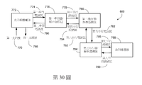
在另一一般方面,一種系統包括:一第一光互連模組,包括:一第一光輸入/輸出埠口,被配置為以下中的至少一個:(i)從第一複數光纖接收複數通道的第一光訊號,或(ii)將複數通道的第二光訊號傳輸到上述第一複數光纖;一第一光子積體電路,被配置為以下中的至少一個:(i)基於上述第一光訊號產生複數第一串行電訊號,或(ii)基於複數第二串行電訊號產生上述第二光訊號。上述第一光互連模組包括複數第一串行器/解串器被配置為以下中的至少一個:(i)基於上述複數第一串行電訊號生成複數第三平行電訊號組,並調節上述電訊號,其中每一第三平行電訊號組基於一對應的第一串行電訊號而生成,或(ii)基於複數第四平行電訊號組生成上述複數第二串行電訊號,其中每一第二串行電訊號基於一對應的第四平行電訊號組而產生。上述第一光互連模組包括複數第二串行器/解串器被配置為以下至少之一:(i)基於上述複數第三平行電訊號組生成複數第五串行電訊號,其中每一第五串行電訊號係基於一對應的第三平行電訊號組而產生,或(ii)基於複數第六串行電訊號生成上述複數第四平行電訊號組,其中每一第四平行電訊號組係基於一對應的第六串行訊號而產生。上述系統包括複數第三串行器/解串器被配置為以下中的至少一個:(i)基於上述複數第五串行電訊號生成複數第七平行電訊號組,並且調節上述電訊號,其中每一第七平行電訊號組係基於一對應的第五串行電訊號而產生,或(ii)基於複數第八平行電訊號組生成上述複數第六串行電訊號,其中每一第六串行電訊號係基於一對應的第八平行電訊號組而產生。上述系統包括一資料處理器,被配置為以下中的至少一個:(i)處理上述複數第七平行電訊號組,或(ii)輸出上述複數第八平行電訊號組。一殼體,被配置為安裝在一伺服器機架中,其中上述殼體包括一前面板、一後面板和一底表面;一印刷電路板或基板,具有限定上述電路板或基板的一長度和一寬度的一第一表面,其中上述印刷電路板或基板相對於上述殼體被定位,使得上述印刷電路板或基板的上述第一表面與上述殼體的上述底表面成一角度,上述角度在45°至90°的範圍內,其中上述第一光互連模組、上述複數第三串行器/解串器和上述資料處理器耦合到上述印刷電路板或基板。至少以下一個:(i) 上述殼體的上述前面板至少部分地由上述印刷電路板或基板形成,(ii) 上述印刷電路板或基板附接到上述殼體的上述前面板,或(iii) 上述印刷電路板或基板實質上平行於上述殼體的上述前面板。上述系統包括至少一入口風扇,安裝在上述殼體的上述前面板上。In another general aspect, a system includes: a first optical interconnect module including: a first optical input/output port configured to at least one of: (i) receive a plurality of optical fibers from a first plurality of optical fibers; the first optical signal of the channel, or (ii) transmit the second optical signal of the plurality of channels to the above-mentioned first complex optical fiber; a first photonic integrated circuit configured as at least one of the following: (i) based on the above-mentioned first optical signal An optical signal generates a plurality of first serial electrical signals, or (ii) generates the above-mentioned second optical signal based on a plurality of second serial electrical signals. The first optical interconnect module includes a plurality of first serializers/deserializers configured to at least one of the following: (i) generate a plurality of third parallel electrical signal groups based on the plurality of first serial electrical signals, and conditioning the electrical signals, wherein each third parallel electrical signal set is generated based on a corresponding first serial electrical signal, or (ii) generating the aforementioned plurality of second serial electrical signals based on a plurality of fourth parallel electrical signal sets, wherein Each second serial electrical signal is generated based on a corresponding fourth parallel electrical signal group. The first optical interconnection module includes a plurality of second serializers/deserializers configured as at least one of the following: (i) generating a plurality of fifth serial electrical signals based on the plurality of third parallel electrical signal groups, wherein each A fifth serial electrical signal is generated based on a corresponding third parallel electrical signal set, or (ii) the plurality of fourth parallel electrical signal sets are generated based on the plurality of sixth serial electrical signals, wherein each fourth parallel electrical signal set The number group is generated based on a corresponding sixth serial signal. The system includes a plurality of third serializers/deserializers configured to at least one of: (i) generate a plurality of seventh parallel sets of electrical signals based on the plurality of fifth serial electrical signals, and condition the electrical signals, wherein Each seventh parallel electrical signal group is generated based on a corresponding fifth serial electrical signal, or (ii) the plurality of sixth serial electrical signals are generated based on a plurality of eighth parallel electrical signal groups, wherein each sixth serial electrical signal The electrical signals are generated based on a corresponding eighth parallel electrical signal group. The above system includes a data processor configured to at least one of: (i) process the plurality of seventh parallel electrical signal groups, or (ii) output the aforementioned plurality of eighth parallel electrical signal groups. A housing configured to be mounted in a server rack, wherein said housing includes a front panel, a rear panel and a bottom surface; a printed circuit board or substrate having a length defining said circuit board or substrate and a first surface of a width, wherein said printed circuit board or substrate is positioned relative to said housing such that said first surface of said printed circuit board or substrate forms an angle with said bottom surface of said housing at In the range of 45° to 90°, wherein the first optical interconnection module, the plurality of third serializers/deserializers and the data processor are coupled to the printed circuit board or substrate. At least one of: (i) said front panel of said housing is formed at least in part from said printed circuit board or substrate, (ii) said printed circuit board or substrate is attached to said front panel of said housing, or (iii) The printed circuit board or substrate is substantially parallel to the front panel of the housing. The system includes at least one inlet fan mounted on the front panel of the housing.

在另一一般方面,一種裝置包括一第一基板,其中上述第一基板包括:一第一主表面和一第二主表面;一第一電觸點陣列,佈置在上述第一主表面上並且在觸點之間具有一第一最小間距;一第二電觸點陣列,佈置在上述第二主表面上並且在觸點之間具有一第二最小間距,其中上述第一最小間距大於上述第二最小間距;以及上述第一電觸點陣列和上述第二電觸點陣列之間的電連接。上述裝置包括具有上述第一主表面和上述第二主表面的一光子積體電路;一第一光連接器部件,被配置為將光耦合到上述光子積體電路的上述第一主表面;一電子積體電路,具有一第一主表面,上述第一主表面具有一第一部分和一第二部分,其中上述第一主表面的上述第一部分電耦合到上述光子積體電路的上述第二主表面,並且上述第一主表面的上述第二部分電耦合到佈置在上述第一基板的上述第二主表面上的上述第二電觸點陣列;一殼體,被配置為安裝在一伺服器機架中,其中上述殼體包括一前面板、一後面板和一底表面;一印刷電路板或一第二基板,具有限定上述電路板或上述第二基板的一長度和一寬度的一第一表面,其中上述印刷電路板或上述第二基板相對於上述殼體被定位,使得上述印刷電路板或上述第二基板的上述第一表面與上述殼體的上述底表面成一角度,上述角度範圍為45°至90°,其中上述第一基板、上述光子積體電路、上述第一光連接器部件及上述電子積體電路耦接至上述印刷電路板或上述第二基板。以下至少一個:(i)上述殼體的上述前面板至少部分地由上述印刷電路板或上述第二基板形成,(ii) 上述印刷電路板或上述第二基板附接到上述殼體的上述前面板,或(iii) 上述印刷電路板或上述第二基板實質上平行於上述殼體的上述前面板。上述裝置包括以下至少一個:(i)安裝在上述殼體的上述前面板的至少一入口風扇,或 (ii)位於上述前面板附近的至少一風扇,其中上述至少一風扇的一風扇葉片的至少一部分在上述至少一風扇的操作期間的至少一段時間內在距上述前面板的一第一距離內,並且上述第一距離小於上述前面板和上述後面板之間的一第二距離的四分之一,並且上述至少一風扇被配置為使空氣吹向上述電子積體電路或熱耦合到上述電子積體電路的一散熱裝置。In another general aspect, an apparatus includes a first substrate, wherein the first substrate includes: a first major surface and a second major surface; a first array of electrical contacts disposed on the first major surface and a first minimum spacing between contacts; a second array of electrical contacts disposed on said second major surface and having a second minimum spacing between contacts, wherein said first minimum spacing is greater than said first minimum spacing two minimum pitches; and an electrical connection between said first array of electrical contacts and said second array of electrical contacts. The device includes a photonic integrated circuit having the first major surface and the second major surface; a first optical connector component configured to couple light to the first major surface of the photonic integrated circuit; Electronic integrated circuit having a first major surface, said first major surface having a first portion and a second portion, wherein said first portion of said first major surface is electrically coupled to said second major surface of said photonic integrated circuit surface, and the second portion of the first major surface is electrically coupled to the second array of electrical contacts disposed on the second major surface of the first substrate; a housing configured to be mounted on a server In the rack, wherein the housing includes a front panel, a rear panel and a bottom surface; a printed circuit board or a second substrate having a first length and a width defining the circuit board or the second substrate A surface, wherein the printed circuit board or the second substrate is positioned relative to the housing such that the first surface of the printed circuit board or the second substrate forms an angle with the bottom surface of the housing, the angle range 45° to 90°, wherein the first substrate, the photonic integrated circuit, the first optical connector component and the electronic integrated circuit are coupled to the printed circuit board or the second substrate. At least one of: (i) the aforementioned front panel of the aforementioned housing is at least partially formed by the aforementioned printed circuit board or the aforementioned second substrate, (ii) the aforementioned printed circuit board or the aforementioned second substrate is attached to the aforementioned front panel of the aforementioned housing The panel, or (iii) the above-mentioned printed circuit board or the above-mentioned second substrate is substantially parallel to the above-mentioned front panel of the above-mentioned casing. Said device comprises at least one of the following: (i) at least one inlet fan mounted on said front panel of said housing, or (ii) at least one fan located near said front panel, wherein at least one fan blade of said at least one fan a portion within a first distance from the front panel for at least a period of time during operation of the at least one fan, and the first distance is less than one quarter of a second distance between the front panel and the rear panel , and the at least one fan is configured to blow air toward the electronic integrated circuit or a heat sink thermally coupled to the electronic integrated circuit.

在另一一般方面,一種裝置,包括:具有一第一主表面和一第二主表面的一印刷電路板;以及一基板。上述基板包括:一第一主表面和一第二主表面;一第一電觸點陣列,佈置在上述第一主表面上並且在上述觸點之間具有一第一最小間距;一第二電觸點陣列,佈置在上述第二主表面上並且在上述觸點之間具有一第二最小間距,其中上述第一最小間距大於上述第二最小間距;以及在上述第一電觸點陣列和上述第二電觸點陣列之間的電連接。上述基板的上述第一主表面被配置為可拆卸地連接到上述印刷電路板的上述第二主表面。上述裝置包括一光子積體電路,具有一第二主表面;一第一光連接器部件,光耦合到上述光子積體電路的上述第二主表面;一電子積體電路,電耦合到上述光子積體電路的上述第二主表面和佈置在上述基板的上述第二主表面上的上述第二電觸點陣列;一殼體,被配置為安裝在一伺服器機架中,其中上述殼體包括一前面板、一後面板和一底表面。上述印刷電路板相對於上述殼體被定位,使得上述印刷電路板的上述表面與上述殼體的上述底表面成一角度,上述角度在45°至90°的範圍內。以下至少一個:(i) 上述殼體的上述前面板至少部分地由上述印刷電路板形成,(ii) 上述印刷電路板附接到上述殼體的上述前面板,或(iii) 上述印刷電路中實質上平行於上述殼體的上述前面板。上述裝置包括至少一入口風扇,安裝在上述殼體的上述前面板上。In another general aspect, an apparatus includes: a printed circuit board having a first major surface and a second major surface; and a substrate. The substrate includes: a first major surface and a second major surface; a first array of electrical contacts disposed on the first major surface and having a first minimum spacing between the contacts; a second electrical contact array an array of contacts disposed on said second major surface and having a second minimum spacing between said contacts, wherein said first minimum spacing is greater than said second minimum spacing; and between said first array of electrical contacts and said An electrical connection between the second array of electrical contacts. The first major surface of the substrate is configured to be detachably connected to the second major surface of the printed circuit board. Said device comprises a photonic integrated circuit having a second major surface; a first optical connector component optically coupled to said second major surface of said photonic integrated circuit; an electronic integrated circuit electrically coupled to said photonic integrated circuit said second major surface of an integrated circuit and said second array of electrical contacts disposed on said second major surface of said substrate; a housing configured to be mounted in a server rack, wherein said housing It includes a front panel, a rear panel and a bottom surface. The printed circuit board is positioned relative to the housing such that the surface of the printed circuit board forms an angle with the bottom surface of the housing, the angle being in the range of 45° to 90°. At least one of: (i) said front panel of said housing formed at least in part by said printed circuit board, (ii) said printed circuit board attached to said front panel of said housing, or (iii) said printed circuit board substantially parallel to the aforementioned front panel of the aforementioned housing. The above-mentioned device includes at least one inlet fan installed on the above-mentioned front panel of the above-mentioned housing.

在另一一般方面,一種裝置包括:複數串行器單元;複數解串器單元;一匯流排處理單元,電耦合到上述串行器單元和上述解串器單元。上述匯流排處理單元被配置為能夠切換上述串行器單元和上述解串行器單元處的訊號。上述裝置包括一殼體,被配置為安裝在一伺服器機架中,其中上述殼體包括一前面板、一後面板和一底表面;一印刷電路板,相對於上述殼體被定位成使得上述印刷電路板的上述表面相對於上述殼體的上述底表面成一角度,並且上述角度在45°到90°的範圍內,其中上述複數串行器單元、上述複數解串器單元以及上述匯流排處理單元耦接上述印刷電路板。以下至少一個:(i) 上述殼體的上述前面板至少部分地由上述印刷電路板形成,(ii) 上述印刷電路板附接到上述殼體的上述前面板,或(iii) 上述印刷電路實質上平行於上述殼體的上述前面板。上述裝置包括至少一入口風扇,安裝在上述殼體的上述前面板上。In another general aspect, an apparatus includes: a plurality of serializer units; a plurality of deserializer units; a bus processing unit electrically coupled to the serializer unit and the deserializer unit. The bus processing unit is configured to switch signals at the serializer unit and the deserializer unit. The apparatus includes a housing configured to be mounted in a server rack, wherein the housing includes a front panel, a rear panel, and a bottom surface; a printed circuit board positioned relative to the housing such that The above-mentioned surface of the above-mentioned printed circuit board forms an angle with respect to the above-mentioned bottom surface of the above-mentioned housing, and the above-mentioned angle is in the range of 45° to 90°, wherein the above-mentioned complex serializer unit, the above-mentioned complex deserializer unit and the above-mentioned bus bar The processing unit is coupled to the printed circuit board. At least one of: (i) said front panel of said housing is formed at least in part from said printed circuit board, (ii) said printed circuit board is attached to said front panel of said housing, or (iii) said printed circuit is substantially above the above-mentioned front panel parallel to the above-mentioned housing. The above-mentioned device includes at least one inlet fan installed on the above-mentioned front panel of the above-mentioned housing.

在另一一般方面,一種裝置包括:一第一串行器/解串器陣列,被配置為將一個或多個第一串行訊號轉換為一或多個平行訊號組;一第二串行器/解串器陣列,被配置為將一個或多個平行訊號組轉換為一個或多個第二串行訊號;一匯流排處理單元,電耦合到上述第一串行器/解串器陣列和上述第二串行器/解串器陣列,其中上述匯流排處理單元被配置為處理上述一或多個平行訊號組,並發送一或多個處理後的平行訊號組到上述第二串行器/解串器陣列;一殼體,被配置為安裝在一伺服器機架中,其中上述殼體包括一前面板、一後面板和一底表面;一印刷電路板,相對於上述殼體被定位,使得上述印刷電路板的上述表面相對於上述殼體的上述底表面成一角度,並且上述角度在45°到90°的範圍內,其中上述第一串行器/解串器陣列、上述第二串行器/解串器陣列以及上述匯流排處理單元耦合到上述印刷電路板。以下至少一個:(i)上述殼體的上述前面板至少部分地由上述印刷電路板形成,(ii)上述印刷電路板附接到上述殼體的上述前面板,或(iii)上述印刷電路板中實質上平行於上述殼體的上述前面板。上述裝置包括至少一入口風扇,安裝在上述殼體的上述前面板上。In another general aspect, an apparatus includes: a first serializer/deserializer array configured to convert one or more first serial signals into one or more sets of parallel signals; a second serial A device/deserializer array configured to convert one or more parallel signal groups into one or more second serial signals; a bus processing unit electrically coupled to the first serializer/deserializer array and the second serializer/deserializer array, wherein the bus processing unit is configured to process the one or more parallel signal groups and send the one or more processed parallel signal groups to the second serial A device/deserializer array; a housing configured to be installed in a server rack, wherein the housing includes a front panel, a rear panel and a bottom surface; a printed circuit board, relative to the housing positioned such that said surface of said printed circuit board is at an angle with respect to said bottom surface of said housing, and said angle is in the range of 45° to 90°, wherein said first serializer/deserializer array, said A second serializer/deserializer array and the bus processing unit are coupled to the printed circuit board. At least one of: (i) said front panel of said housing is at least partially formed by said printed circuit board, (ii) said printed circuit board is attached to said front panel of said housing, or (iii) said printed circuit board The center is substantially parallel to the above-mentioned front panel of the above-mentioned housing. The above-mentioned device includes at least one inlet fan installed on the above-mentioned front panel of the above-mentioned housing.

在另一一般方面,一種裝置包括:一印刷電路板,具有一第一主表面和第二主表面;以及一基板。上述基板包括:一第一主表面和一第二主表面;一第一電觸點陣列,佈置在上述第一主表面上並且在上述觸點之間具有一第一最小間距;一第二電觸點陣列,佈置在上述第二主表面上並且在上述觸點之間具有一第二最小間距,其中上述第一最小間距大於上述第二最小間距;一第三電觸點陣列,佈置在上述第一主表面上;在上述第一電觸點陣列和上述第二電觸點陣列的一第一子集之間的第一電連接;以及在上述第三電觸點陣列和上述第二電觸點陣列的一第二子集之間的第二電連接。上述基板的上述第一主表面被配置為可拆卸地連接到上述印刷電路板的上述第二主表面。上述裝置包括一電子積體電路,電耦合到佈置在上述基板的上述第二主表面上的上述第二電觸點陣列;一光子積體電路,具有一第二主表面和佈置在上述第二主表面上的電觸點,上述電觸點電耦合到佈置在上述基板的上述第一主表面上的上述第三電觸點陣列;一第一光連接器部件,光耦合到上述光子積體電路;一殼體,被配置為安裝在一伺服器機架中,其中上述殼體包括一前面板、一後面板和一底表面。上述印刷電路板相對於上述殼體被定位,使得上述印刷電路板的上述第一主表面相對於上述殼體的上述底表面成一角度,上述角度在45°至90°的範圍內。至少一個:(i) 上述殼體的上述前面板至少部分地由上述印刷電路板形成,(ii) 上述印刷電路板附接到上述殼體的上述前面板,或(iii) 上述印刷電路實質上平行於上述殼體的上述前面板。上述裝置包括至少一入口風扇,安裝在上述殼體的上述前面板上。In another general aspect, an apparatus includes: a printed circuit board having a first major surface and a second major surface; and a substrate. The substrate includes: a first major surface and a second major surface; a first array of electrical contacts disposed on the first major surface and having a first minimum spacing between the contacts; a second electrical contact array an array of contacts disposed on said second major surface and having a second minimum spacing between said contacts, wherein said first minimum spacing is greater than said second minimum spacing; a third array of electrical contacts disposed on said on the first major surface; a first electrical connection between said first array of electrical contacts and a first subset of said second array of electrical contacts; and between said third array of electrical contacts and said second array of electrical contacts A second electrical connection between a second subset of the contact array. The first major surface of the substrate is configured to be detachably connected to the second major surface of the printed circuit board. Said device comprises an electronic integrated circuit electrically coupled to said second array of electrical contacts disposed on said second major surface of said substrate; a photonic integrated circuit having a second major surface and disposed on said second major surface. electrical contacts on a major surface electrically coupled to said third array of electrical contacts disposed on said first major surface of said substrate; a first optical connector component optically coupled to said photonic integrated body The circuit; a housing configured to be mounted in a server rack, wherein the housing includes a front panel, a rear panel and a bottom surface. The printed circuit board is positioned relative to the housing such that the first major surface of the printed circuit board is at an angle in the range of 45° to 90° relative to the bottom surface of the housing. At least one of: (i) said front panel of said housing is at least partially formed by said printed circuit board, (ii) said printed circuit board is attached to said front panel of said housing, or (iii) said printed circuit is substantially parallel to the aforementioned front panel of the aforementioned housing. The above-mentioned device includes at least one inlet fan installed on the above-mentioned front panel of the above-mentioned housing.

在另一一般方面,一種方法,包括:從複數光纖接收複數通道的第一光訊號;基於接收到的上述光訊號產生複數第一串行電訊號,其中每一第一串行電訊號是基於上述複數通道的第一光訊號中的一個通道產生的;基於上述複數第一串行電訊號產生複數第一平行電訊號組,並調節上述電訊號,其中每一第一平行電訊號組是基於一對應的第一串行電訊號產生的;根據上述複數第一平行電訊號組產生複數第二串行電訊號,其中每一第二串行電訊號是根據一對應的第一平行電訊號組產生的;以及去除由被配置為處理上述複數第二串行電訊號或從上述複數第二串行電訊號導出的電訊號的至少一資料處理器產生的熱,其中去除熱包括使用以下至少一個:(i)至少一入口風扇,耦接到上述殼體的上述前面板,上述殼體容納上述至少一資料處理器以增加上述殼體中的氣流,或 (ii) 至少一入口風扇,位於上述前面板附近,其中在上述至少一入口風扇的操作期間,上述至少一入口風扇的一風扇葉片的至少一部分在至少一段時間距容納上述至少一資料處理器的一殼體的一前面板的一第一距離內,上述第一距離小於上述殼體的上述前面板和一後面板之間的一第二距離的三分之一,以增加上述殼體中的空氣流動。In another general aspect, a method includes: receiving a plurality of channels of first optical signals from a plurality of optical fibers; generating a plurality of first serial electrical signals based on the received optical signals, wherein each first serial electrical signal is based on Generated by one channel of the first optical signal of the plurality of channels; generate a plurality of first parallel electrical signal groups based on the aforementioned plurality of first serial electrical signals, and adjust the aforementioned electrical signals, wherein each first parallel electrical signal group is based on Generated by a corresponding first serial electrical signal; generating a plurality of second serial electrical signals according to the plurality of first parallel electrical signal groups, wherein each second serial electrical signal is based on a corresponding first parallel electrical signal group generated; and removing heat generated by at least one data processor configured to process said plurality of second serial electrical signals or electrical signals derived from said plurality of second serial electrical signals, wherein removing heat comprises using at least one of (i) at least one inlet fan coupled to said front panel of said housing housing said at least one data processor to increase airflow in said housing, or (ii) at least one inlet fan located in said Adjacent to the front panel, wherein during operation of the at least one inlet fan, at least a portion of a fan blade of the at least one inlet fan is separated for at least a period of time from a first section of a front panel of a housing housing the at least one data processor Within a distance, the first distance is less than one-third of a second distance between the front panel and a rear panel of the housing to increase air flow in the housing.

在另一一般方面,一種裝置包括:一電路板;一第一結構,附接到上述電路板,其中上述第一結構被配置為使一光模組能夠可拆卸地耦合到上述第一結構,並且上述光模組被配置為使一光纖連接器能夠可拆卸地耦合到上述光模組;一殼體,被配置為安裝在一伺服器機架中,其中上述殼體包括一前面板、一後面板和一底表面。上述電路板相對於上述殼體被定位,使得上述電路板的一表面相對於上述殼體的上述底表面成一角度,上述角度在45°至90°的範圍內。至少以下一個:(i) 上述殼體的上述前面板至少部分地由上述電路板形成,(ii) 上述電路板附接到上述殼體的上述前面板,或(iii) 上述電路板實質上是平行於上述殼體的上述前面板;以及至少一入口風扇,安裝在上述殼體的上述前面板上。In another general aspect, an apparatus includes: a circuit board; a first structure attached to the circuit board, wherein the first structure is configured to enable an optical module to be detachably coupled to the first structure, And the above-mentioned optical module is configured so that an optical fiber connector can be detachably coupled to the above-mentioned optical module; a casing is configured to be installed in a server rack, wherein the above-mentioned casing includes a front panel, a rear panel and a bottom surface. The circuit board is positioned relative to the housing such that a surface of the circuit board is at an angle with respect to the bottom surface of the housing, the angle being in the range of 45° to 90°. at least one of: (i) said front panel of said housing is at least partially formed by said circuit board, (ii) said circuit board is attached to said front panel of said housing, or (iii) said circuit board is substantially Parallel to the above-mentioned front panel of the above-mentioned casing; and at least one inlet fan installed on the above-mentioned front panel of the above-mentioned casing.

在另一一般方面,一種裝置包括:一光模組,被配置為可移除地耦合到附接到一電路板的一第一結構,其中上述光模組包括一光子積體電路,上述光模組被配置為在上述光模組被耦合至上述第一結構時將上述光子積體電路保持在適當位置,並使得來自上述光子積體電路的電訊號能夠傳輸至上述電路板。上述光模組被配置為使一光纖連接器能夠可拆卸地耦合到上述光模組,其中上述光模組被配置為使來自上述光纖連接器的光訊號能夠傳輸到上述光子積體電路。上述裝置包括一殼體,被配置為安裝在一伺服器機架中,其中上述殼體包括一前面板、一後面板和一底表面。上述電路板相對於上述殼體被定位,使得上述電路板的一表面相對於上述殼體的上述底表面成一角度,上述角度在45°至90°的範圍內。以下至少一個:(i) 上述殼體的上述前面板至少部分地由上述電路板形成,(ii) 上述電路板附接到上述殼體的上述前面板,或(iii) 上述電路板實質上平行於上述殼體的上述前面板。上述裝置包括至少一入口風扇,安裝在上述殼體的上述前面板上。In another general aspect, an apparatus includes: an optical module configured to be removably coupled to a first structure attached to a circuit board, wherein the optical module includes a photonic integrated circuit, the optical The module is configured to hold the photonic integrated circuit in place when the optical module is coupled to the first structure and to enable transmission of electrical signals from the photonic integrated circuit to the circuit board. The optical module is configured to allow a fiber optic connector to be detachably coupled to the optical module, wherein the optical module is configured to transmit optical signals from the optical fiber connector to the photonic integrated circuit. The apparatus includes a housing configured to be installed in a server rack, wherein the housing includes a front panel, a rear panel and a bottom surface. The circuit board is positioned relative to the housing such that a surface of the circuit board is at an angle with respect to the bottom surface of the housing, the angle being in the range of 45° to 90°. At least one of: (i) said front panel of said housing is at least partially formed by said circuit board, (ii) said circuit board is attached to said front panel of said housing, or (iii) said circuit boards are substantially parallel on the above-mentioned front panel of the above-mentioned casing. The above-mentioned device includes at least one inlet fan installed on the above-mentioned front panel of the above-mentioned housing.

在另一一般方面,一種裝置包括:一機架式設備,其中上述機架式設備包括:一殼體,被配置為安裝在一伺服器機架中,其中上述殼體包括一前面板、一後面板、一底面板和一頂面板;一第一電路板,具有限定上述第一電路板的一長度和一寬度的一第一表面,其中上述第一電路板相對於上述殼體被定位,使得上述第一電路板的上述第一表面相對於上述殼體的上述底面板成一角度,上述角度在45°至90°的範圍內。以下至少一個:(i)上述殼體的上述前面板至少部分地由上述第一電路板形成,(ii) 上述第一電路板附接到上述殼體的上述前面板,(iii) 上述第一電路板實質上平行於上述殼體的上述前面板,或(iv) 上述第一電路板與上述前面板間隔開且上述第一電路板與上述前面板之間的一距離不超過12英吋。上述機架式設備包括至少一資料處理器,安裝在上述第一電路板上,用於處理資料;一散熱模組,熱耦合到上述至少一資料處理器;用於上述至少一資料處理器的至少一通訊介面,其中上述至少一通訊介面耦合到上述第一電路板;以及一主動氣流控制模組,用於將進氣引導至上述散熱模組,其中上述主動氣流控制模組包括一入口風扇和一出口風扇,上述入口風扇位於上述殼體的一前半部,上述出口風扇位於位於上述殼體的一後半部。In another general aspect, an apparatus includes: a rack-mountable device, wherein the rack-mountable device includes: a housing configured to be mounted in a server rack, wherein the housing includes a front panel, a a rear panel, a bottom panel and a top panel; a first circuit board having a first surface defining a length and a width of said first circuit board, wherein said first circuit board is positioned relative to said housing, The first surface of the first circuit board forms an angle with respect to the bottom panel of the casing, and the angle is within a range of 45° to 90°. at least one of: (i) said front panel of said housing is at least partially formed by said first circuit board, (ii) said first circuit board is attached to said front panel of said housing, (iii) said first The circuit board is substantially parallel to the front panel of the housing, or (iv) the first circuit board is spaced apart from the front panel with a distance between the first circuit board and the front panel not exceeding 12 inches. The above-mentioned rack-mounted equipment includes at least one data processor installed on the above-mentioned first circuit board for processing data; a heat dissipation module thermally coupled to the above-mentioned at least one data processor; at least one communication interface, wherein the at least one communication interface is coupled to the first circuit board; and an active airflow control module for guiding the air intake to the heat dissipation module, wherein the active airflow control module includes an inlet fan and an outlet fan, the inlet fan is located at a front half of the casing, and the outlet fan is located at a rear half of the casing.

在另一一般方面,一種系統,包括:一伺服器機架;複數機架式伺服器,安裝在上述伺服器機架中。每個機架式伺服器包括:一殼體,具有在16至20英吋範圍內的一寬度,在1至12英吋範圍內的一高度,其中上述殼體包括一前面板、一後面板和一底表面;一第一電路板,具有限定上述第一電路板的一長度和一寬度的一第一表面,其中上述第一電路板相對於上述殼體被定位,使得上述第一電路板的上述第一表面相對於上述殼體的上述底表面成一角度,上述角度在45°到90°的範圍內。以下至少一個:(i) 上述殼體的上述前面板至少部分地由上述第一電路板形成,(ii) 上述第一電路板附接到上述殼體的上述前面板,(iii) 上述第一電路板實質上平行於上述殼體的上述前面板,或(iv) 上述第一電路板與上述前面板間隔開且上述第一電路板與上述前面板之間的一距離不超過12英吋;上述機架式伺服器包括至少一資料處理器,安裝在上述第一電路板上,用於處理資料;至少一通訊介面,耦接至上述第一電路板,其中每一通訊介面用以耦接一外部線纜;以及至少一入口風扇,安裝在上述殼體的一前半部中,上述入口風扇具有相對於上述前面板的一平面成一角度θ的一旋轉軸,上述角度θ是沿平行於上述底面板的一平面所測量,並且θ ≤ 45°。In another general aspect, a system includes: a server rack; a plurality of rack-mounted servers mounted in the server rack. Each rack server includes: a housing having a width in the range of 16 to 20 inches and a height in the range of 1 to 12 inches, wherein the housing includes a front panel, a rear panel and a bottom surface; a first circuit board having a first surface defining a length and a width of the first circuit board, wherein the first circuit board is positioned relative to the housing such that the first circuit board The above-mentioned first surface of the above-mentioned housing forms an angle with respect to the above-mentioned bottom surface of the above-mentioned housing, and the above-mentioned angle is in the range of 45° to 90°. At least one of: (i) said front panel of said housing is at least partially formed by said first circuit board, (ii) said first circuit board is attached to said front panel of said housing, (iii) said first the circuit board is substantially parallel to said front panel of said housing, or (iv) said first circuit board is spaced apart from said front panel with a distance between said first circuit board and said front panel not exceeding 12 inches; The rack-mounted server includes at least one data processor mounted on the first circuit board for processing data; at least one communication interface coupled to the first circuit board, wherein each communication interface is used for coupling an external cable; and at least one inlet fan mounted in a front half of said housing, said inlet fan having an axis of rotation at an angle θ with respect to a plane of said front panel, said angle θ being along a direction parallel to said Measured in one plane of the bottom panel, and θ ≤ 45°.

在另一一般方面,一種裝置包括:一機架式設備,包括:一殼體,被配置為安裝在一伺服器機架中,其中上述殼體包括一前面板、一後面板、一底面板、一頂面板和側面板,其中複數光連接器安裝在上述前面板上,每個光連接器被配置為光耦合到一光纖互連電纜;以及一主動氣流控制模組,被配置為主動控制在上述殼體內上述前面板後面12英吋內的一第一區域中的氣流,以最佳化來自位於上述第一區域中的一資料處理器的散熱。In another general aspect, an apparatus includes: a rack-mountable device including: a housing configured to be mounted in a server rack, wherein the housing includes a front panel, a rear panel, and a bottom panel , a top panel and side panels, wherein a plurality of optical connectors are mounted on the aforementioned front panel, each optical connector configured to be optically coupled to an optical fiber interconnection cable; and an active airflow control module configured to actively control Airflow in a first area within the enclosure within 12 inches behind the front panel to optimize heat dissipation from a data processor located in the first area.

其他方面包括上述特徵和其他特徵的其他組合,以方法、裝置、系統、程序產品和其他方式表示。Other aspects include other combinations of the above features and other features, expressed in methods, apparatus, systems, program products, and otherwise.

使用光訊號互連電子晶片封裝可以具有這樣的優點:與電輸入/輸出相比,光訊號可以以每單位面積更高的輸入/輸出容量來傳遞。The use of optical signals to interconnect electronic chip packages can have the advantage that optical signals can be transferred with a higher I/O capacity per unit area than electrical I/O.

本說明書中描述主題的特定實施例可以被實施以實現以下一或多個的優點。該資料處理系統具有高功率效率、低建設成本、低營運成本、重新配置光網路連接的高度靈活性。本文中描述的散熱解決方案允許有效消散由資料處理器處理由光纖電纜承載大量資料所產生的熱。Particular embodiments of the subject matter described in this specification can be implemented to realize one or more of the following advantages. The data processing system has high power efficiency, low construction cost, low operating cost, and high flexibility for reconfiguring optical network connections. The thermal solution described herein allows for efficient dissipation of heat generated by data processors processing large amounts of data carried by fiber optic cables.

將在下面的附圖和說明中闡述在本說明書中描述的主題的一個或多個實施例的細節。主題的其它特徵、方面和優勢從說明、附圖和請求項將變得顯而易見。The details of one or more embodiments of the subject matter described in this specification are set forth in the accompanying drawings and the description below. Other features, aspects and advantages of the subject matter will become apparent from the description, drawings and claims.

除另有所指外,本文所用的所有技術和科學術語與本發明所屬領域技術人員所理解的具有相同意義。在與透過引用併入本文的專利申請或專利申請公開衝突的情況下,將以包括定義在內的本說明書為準。Unless defined otherwise, all technical and scientific terms used herein have the same meaning as commonly understood by one of ordinary skill in the art to which this invention belongs. In case of conflict with a patent application or patent application publication incorporated herein by reference, the present specification, including definitions, will control.

本文描述了一種用於高頻寬資料處理的新型系統,包括用於將光纖束耦合到資料處理積體電路(例如,網路交換機、中央處理單元、圖形處理器單元、張量處理單元、數位訊號處理器和/或其他特定應用積體電路(ASIC))的新型輸入/輸出介面模組,處理透過光纖傳輸的資料。在一些實施方式中,資料處理積體電路安裝在靠近輸入/輸出介面模組定位的電路板上經過電路板上相對短的電訊號路徑。輸入/輸出介面模組包括允許使用者方便地將輸入/輸出介面模組連接到電路板或從電路板斷開的第一連接器。輸入/輸出介面模組包括允許使用者方便地將光纖束連接到輸入/輸出介面模組或從輸入/輸出介面模組斷開的第二連接器。在一些實施方式中,提供了具有前面板的機架安裝系統,其中電路板(其支撐輸入/輸出介面模組和資料處理積體電路)垂直安裝在與前面板基本平行並位於其附近的方向上。前面板。在一些示例中,電路板用作前面板或前面板的一部分。輸入/輸出介面模組的第二連接器面向機架安裝系統的正面,以允許使用者方便地將光纖束連接到系統或從系統斷開。This paper describes a novel system for high-bandwidth data processing, including methods for coupling fiber optic bundles to data-processing integrated circuits (e.g., network switches, central processing units, graphics processor units, tensor processing units, digital signal processing devices and/or other application-specific integrated circuits (ASICs)) to process data transmitted over fiber optics. In some embodiments, the data processing integrated circuit is mounted on a circuit board positioned adjacent to the I/O interface module via relatively short electrical signal paths on the circuit board. The I/O interface module includes a first connector allowing the user to conveniently connect or disconnect the I/O interface module to or from the circuit board. The I/O interface module includes a second connector that allows a user to conveniently connect or disconnect the fiber optic bundle to and from the I/O interface module. In some embodiments, a rack mount system having a front panel is provided, wherein the circuit board (which supports the input/output interface modules and the data processing IC) is vertically mounted in an orientation substantially parallel to and adjacent to the front panel superior. front panel. In some examples, the circuit board is used as a front panel or as part of a front panel. The second connector of the I/O interface module faces the front of the rack mount system to allow the user to conveniently connect or disconnect the fiber optic bundle to or from the system.

在一些實施方式中,高頻寬資料處理系統的一個特點是,透過將支持輸入/輸出介面模組和資料處理積體電路的電路板垂直安裝在前面板附近,或者將電路板配置為前面板或前面板的一部分,光訊號可以從光纖透過輸入/輸出介面模組透過相對較短的電訊號路徑路由到資料處理積體電路。這允許傳輸到資料處理積體電路的訊號具有高位元率(例如,超過50 Gbps),同時保持低串音、低失真和低噪音,從而降低資料處理系統的功耗和佔用空間。In some embodiments, a high bandwidth data processing system is characterized by mounting a circuit board supporting an input/output interface module and a data processing integrated circuit vertically near the front panel, or by configuring the circuit board as a front panel or front panel The part of the panel where optical signals can be routed from the optical fiber through the I/O interface module to the data processing IC through a relatively short electrical signal path. This allows signals transmitted to data processing ICs to have high bit rates (eg, over 50 Gbps) while maintaining low crosstalk, low distortion, and low noise, thereby reducing the power consumption and footprint of data processing systems.

在一些實施方式中,高頻寬資料處理系統的一個特徵是維護和維修的成本與傳統系統相比可以更低。例如,輸入/輸出介面模組和光纖電纜被配置為可拆卸的,有缺陷的輸入/輸出介面模組可以在不拆開資料處理系統並且不必重新路由任何光纖的情況下更換。高頻寬資料處理系統的另一個特點是,由於使用者可以由機架安裝系統的前面板輕鬆地將光纖束連接或斷開輸入/輸出介面模組,因此透過光纖到各種資料處理積體電路的高位元率訊號路由設定不但具有彈性且易於修改。例如,將數百根光纖束連接到機架安裝系統的光連接器幾乎就像將USB電纜插入USB埠口一樣簡單。高頻寬資料處理系統的另一個特點是輸入/輸出介面模組可以使用相對標準、低成本和節能的組件來製作,因此輸入/輸出介面模組的初始硬體成本和後續營運成本與傳統系統相比相對較低。In some embodiments, a feature of high bandwidth data processing systems is that maintenance and repair costs can be lower compared to conventional systems. For example, the I/O interface modules and fiber optic cables are configured to be removable, and a defective I/O interface module can be replaced without dismantling the data processing system and without rerouting any optical fibers. Another feature of the high-bandwidth data processing system is that since the user can easily connect or disconnect the optical fiber bundle from the front panel of the rack-mounted system to the input/output interface module, through the optical fiber to the high-level of various data processing integrated circuits The meta-rate signal routing settings are not only flexible but also easy to modify. For example, connecting hundreds of fiber optic bundles to the optical connectors of a rack-mount system is almost as simple as plugging a USB cable into a USB port. Another characteristic of high-bandwidth data processing systems is that I/O interface modules can be fabricated using relatively standard, low-cost, and energy-efficient components, so the initial hardware cost and subsequent operating costs of I/O interface modules are compared with traditional systems relatively low.

在一些實施方式中,光互連可以將光轉發器與電子處理晶片共同封裝和/或共同集成。對於電子處理晶片封裝而言,這種消耗相對低功率且能充分穩健的抗顯著溫度變化的轉發器解決方案是有用的。在一些實施方式中,高速和/或高頻寬資料處理系統可以包括大規模空間平行的光互連解決方案,其將訊息多路復用到相對較少的波長上並且使用相對大量的平行空間路徑進行晶片至晶片互連。例如,相對大量的平行空間路徑可以使用連接器結構佈置在二維陣列中,例如在2020年3月11日提交的美國專利申請16/816,171中公開的那些,並且透過引用將其整體併入本文。In some embodiments, an optical interconnect may co-package and/or co-integrate an optical transponder with an electronic processing die. Such transponder solutions that consume relatively low power and are sufficiently robust against significant temperature variations are useful for electronic processing chip packages. In some embodiments, a high-speed and/or high-bandwidth data processing system may include a massively spatially parallel optical interconnect solution that multiplexes information onto a relatively small number of wavelengths and uses a relatively large number of parallel spatial paths. Die-to-die interconnects. For example, a relatively large number of parallel spatial pathways can be arranged in a two-dimensional array using connector structures, such as those disclosed in U.S. Patent Application 16/816,171, filed March 11, 2020, and incorporated herein by reference in its entirety .

第1圖示出了通訊系統100的框圖,該通訊系統100結合了本文檔中描述的一個或多個新穎特徵。在一些實施方式中,系統100包括節點101_1到101_6(統稱為101),在一些實施例中,每個節點可以包括以下中的一個或多個:光通訊設備、電子和/或光交換設備、電子和/或光學路徑由設備、網路控制設​​備、流量控制設備、同步設備、計算設備和資料儲存設備。節點101_1到101_6可以透過光纖鏈路102_1到102_12(統稱為102)適當地互連,在節點內的通訊設備之間建立通訊路徑。光纖鏈路102可以包括在2020年3月18日提交的美國專利申請16/822,103中描述的光纖電纜,本文完整引用該專利申請。系統100還可以包括一個或多個光電源供應器模組103,產生一個或多個光輸出,每個光輸出包括一個或多個連續波(CW)光場和/或者用於節點101_1至101_6的一個或多個光通訊設備中的一個或多個光脈衝序列。為了說明的目的,圖1中僅示出了一個這樣的光電源供應器模組103。本領域普通技術人員可理解,一些實施例可具有多於一個的光電源供應器模組103,其適當地分佈在系統100上,且這樣的多個電源模組可以同步,例如,使用一些在2020年4月14日提交的美國專利申請16/847,705所公開的技術,並於本文完整引用。Figure 1 shows a block diagram of a communication system 100 that incorporates one or more of the novel features described in this document. In some implementations, the system 100 includes nodes 101_1 to 101_6 (collectively referred to as 101), and in some embodiments, each node may include one or more of the following: optical communication equipment, electronic and/or optical switching equipment, Electronic and/or optical paths consist of equipment, network control equipment, flow control equipment, synchronization equipment, computing equipment, and data storage equipment. Nodes 101_1 to 101_6 may be suitably interconnected via optical fiber links 102_1 to 102_12 (collectively referred to as 102 ) to establish communication paths between communication devices within the nodes. Fiber optic link 102 may comprise a fiber optic cable as described in US Patent Application 16/822,103, filed March 18, 2020, which is incorporated herein by reference in its entirety. System 100 may also include one or more optical power supply modules 103 that generate one or more optical outputs, each optical output comprising one or more continuous wave (CW) optical fields and/or for nodes 101_1 to 101_6 One or more optical pulse sequences in one or more optical communication devices. For illustrative purposes, only one such optical power supply module 103 is shown in FIG. 1 . Those of ordinary skill in the art will understand that some embodiments may have more than one optical power supply module 103, suitably distributed over the system 100, and such multiple power supply modules may be synchronized, for example, using some Technology disclosed in U.S. Patent Application 16/847,705, filed April 14, 2020, and incorporated herein by reference in its entirety.

一些終端間通訊路徑可經由光電源供應器模組103(例如,參見節點101_2和101_6之間的通訊路徑)。例如,節點101_2和101_6之間的通訊路徑可以由光纖鏈路102_7和102_8共同建立,由此來自光電源供應器模組103的光被多路復用到光纖鏈路102_7和102_8上。Some inter-terminal communication paths may pass through the optical power supply module 103 (for example, refer to the communication path between nodes 101_2 and 101_6). For example, the communication path between the nodes 101_2 and 101_6 can be jointly established by the fiber optic links 102_7 and 102_8, whereby the light from the optical power supply module 103 is multiplexed on the fiber optic links 102_7 and 102_8.

一些終端間通訊路徑可以透過一個或多個光多工單元104(例如,參見節點101_2和101_6之間的通訊路徑)。例如,節點101_2和101_6之間的通訊路徑可以由光纖鏈路102_10和102_11共同建立。光多工單元104還藉由鏈路102_9連接以接收來自光電源供應器模組103的光,且因此可將上述接收到的光多路復用至光纖鏈路102_10和102_11上。Some of the inter-terminal communication paths may pass through one or more optical multiplexing units 104 (eg, see the communication path between nodes 101_2 and 101_6). For example, the communication path between nodes 101_2 and 101_6 can be jointly established by optical fiber links 102_10 and 102_11. The optical multiplexing unit 104 is also connected by the link 102_9 to receive the light from the optical power supply module 103, and thus can multiplex the received light onto the optical fiber links 102_10 and 102_11.

一些終端間通訊路徑可以透過一個或多個光交換單元105(例如,參見節點101_1和101_4之間的通訊路徑)。例如,節點101_1和101_4之間的通訊路徑可以由光纖鏈路102_3和102_12共同建立,由此來自光纖鏈路102_3和102_4的光被靜態或動態地引導到光纖鏈路102_12。Some inter-terminal communication paths may pass through one or more optical switching units 105 (for example, see the communication paths between nodes 101_1 and 101_4). For example, a communication path between nodes 101_1 and 101_4 may be jointly established by fiber optic links 102_3 and 102_12, whereby light from fiber optic links 102_3 and 102_4 is statically or dynamically directed to fiber optic link 102_12.

如本文所用,術語「網路元件」指代在系統100內產生、調變、處理或接收用於通訊目的的光的任何元件。示例網路元件包括節點101、光電源供應器模組103、光多工單元104和光交換單元105。As used herein, the term "network element" refers to any element within system 100 that generates, modulates, processes, or receives light for communication purposes. Example network elements include node 101 , optical power supply module 103 , optical multiplexing unit 104 and optical switching unit 105 .

一些光分佈路徑可以透過一個或多個網路元件。例如,光電源供應器模組103可以透過光纖鏈路102_7、102_4和102_12向節點101_4提供光,讓光通過網路元件101_2和105。Some light distribution paths may pass through one or more network elements. For example, the optical power supply module 103 can provide light to the node 101_4 through the optical fiber links 102_7 , 102_4 and 102_12 , allowing the light to pass through the network elements 101_2 and 105 .

通訊系統100的各種元件可受益於光互連的使用,其可以使用包含光電設備的光子積體電路,與包括積體電路的電子晶片共同封裝和/或共同集成。Various components of the communication system 100 may benefit from the use of optical interconnects, which may be co-packaged and/or co-integrated with an electronic die including the integrated circuits using photonic integrated circuits including optoelectronic devices.

如本文所用,術語「光子積體電路」(或PIC)應解釋為涵蓋平面光波電路(PLC)、積體光電設備、基板上的晶圓級產品、單個光子晶片和管芯以及混合設備。基板可由如一種或多種陶瓷材料或有機「高密度積層(HDBU)」製成。可用於製造各種光子積體電路的示例材料系統可包括但不限於III-V半導體材料、矽光子學、矽基矽產品、基於矽玻璃的平面光波電路、聚合物積體平台、鋰鈮酸鹽及其衍生物、非線性光學材料等。封裝設備(例如,鏈路和/或封裝晶片)和未封裝設備(例如,管芯)都可以稱為平面光波電路。As used herein, the term "photonic integrated circuit" (or PIC) should be construed to encompass planar lightwave circuits (PLCs), integrated optoelectronic devices, wafer-scale products on substrates, individual photonic wafers and dies, and hybrid devices. The substrate can be made of, for example, one or more ceramic materials or organic "high density build-up (HDBU)". Example material systems that can be used to fabricate various photonic integrated circuits may include, but are not limited to, III-V semiconductor materials, silicon photonics, silicon-on-silicon products, silicon-glass-based planar lightwave circuits, polymeric integrated platforms, lithium niobate And its derivatives, nonlinear optical materials, etc. Both packaged devices (eg, links and/or packaged dies) and unpackaged devices (eg, dies) can be referred to as planar lightwave circuits.

光子積體電路用於電信、儀器控制和訊號處理領域的各種應用。在一些實現中,光子積體電路使用光波導來實現和/或互連各種電路組件,例如光交換機、耦合器、路由器、分路器、多路多工器/解多路多工器、濾波器、調變器、分相器、雷射、放大器、波長轉換器、光電(O/E)和電光(E/O)訊號轉換器等。例如,光子積體電路中的波導可以是晶片上固態光導體,因波導芯和包層之間的折射率對比而可以導引光。光子積體電路可以包括平面基板,光電設備通過增材製造工藝生長在該基板上和/或光電設備透過減材製造工藝蝕刻到該基板上,例如,使用光刻和化學處理步驟的多步驟序列。Photonic integrated circuits are used in a variety of applications in telecommunications, instrument control and signal processing. In some implementations, photonic integrated circuits use optical waveguides to implement and/or interconnect various circuit components, such as optical switches, couplers, routers, splitters, multiplexers/demultiplexers, filtering Devices, modulators, phase splitters, lasers, amplifiers, wavelength converters, photoelectric (O/E) and electro-optic (E/O) signal converters, etc. For example, a waveguide in a photonic integrated circuit can be a solid-state photoconductor on a wafer that guides light due to the refractive index contrast between the waveguide core and cladding. Photonic integrated circuits may include planar substrates on which optoelectronic devices are grown by additive manufacturing processes and/or where optoelectronic devices are etched by subtractive manufacturing processes, for example, using a multi-step sequence of photolithographic and chemical processing steps .

在一些實施方式中,「光電設備」可以在光和電流(或電壓)上運行,並且可以包括以下中的一個或多個構件:(i)電驅動光源,例如雷射二極管;(ii)光放大器;(iii)光電轉換器,例如光電二極管;(iv)可以控制光的傳播和/或某些特性(例如,幅度、相位、偏振)的光電組件,例如光調變器或交換機。對應的光電電路可以另外包括一個或多個光學元件和/或一個或多個電子組件,其使得能夠以與電路的預期功能一致的方式使用電路的光電設備。一些光電設備可以使用一個或多個光子積體電路來實現。In some embodiments, an "optoelectronic device" can operate on light and current (or voltage), and can include one or more of the following components: (i) an electrically driven light source, such as a laser diode; (ii) an optical Amplifiers; (iii) optoelectronic converters, such as photodiodes; (iv) optoelectronic components that can control the propagation and/or certain characteristics (eg, amplitude, phase, polarization) of light, such as optical modulators or switches. A corresponding optoelectronic circuit may additionally comprise one or more optical elements and/or one or more electronic components which enable the use of the optoelectronic device of the circuit in a manner consistent with the intended function of the circuit. Some optoelectronic devices can be realized using one or more photonic integrated circuits.

本文所用術語「積體電路」(IC)應被解釋為包括非封裝管芯和封裝管芯兩者。在典型的積體電路製造工藝中,管芯(晶片)是使用矽晶圓或其他合適材料以相對較大的批量生產的。可以使用光刻和化學處理步驟等多步驟序列在晶圓上逐漸創建電路和光學電路,然後將每個晶圓切割(「切塊」)成許多塊(晶片、管芯),每塊都包含正在製造的電路的相應副本。每個單獨的管芯可以在併入更大的電路之前進行適當的封裝,或者不進行封裝。The term "integrated circuit" (IC) as used herein should be construed to include both unpackaged and packaged die. In a typical integrated circuit manufacturing process, dies (wafers) are produced in relatively large batches using silicon wafers or other suitable materials. Electrical and optical circuits can be incrementally created on the wafer using a multi-step sequence of photolithographic and chemical processing steps, and each wafer is then diced (“diced”) into many pieces (wafers, dies), each containing A corresponding copy of the circuit being fabricated. Each individual die may be properly packaged or not packaged before being incorporated into a larger circuit.

術語「混合電路(hybrid circuit)」可以指由多個單片積體電路以及可能的一些離散電路組件構成的多組件電路,所有這些組件都彼此附接並通電安裝在公共基座、載體或基板上。代表性混合電路可以包括(i)一個或多個封裝或非封裝管芯,其中一些或所有管芯包括光學、光電和/或半導體設備,以及(ii)一個或多個可選離散元件,例如連接器、電阻、電容和電感。積體電路、管芯和離散元件之間的電連接可以示例性的使用圖案化的導電(例如金屬)層、球柵陣列、焊料凸塊、引線鍵合等。電連接是可拆卸的,例如,透過使用平面網格陣列和/或壓縮插入器。個別的積體電路可以包括一個或多個相應基板、一個或多個再分佈層(RDL)、一個或多個中介層、一個或多個層壓板等的任何組合。The term "hybrid circuit" may refer to a multi-component circuit consisting of multiple monolithic integrated circuits and possibly some discrete circuit components, all attached to each other and electrically mounted on a common base, carrier or substrate superior. A representative hybrid circuit may include (i) one or more packaged or unpackaged die, some or all of which include optical, optoelectronic and/or semiconductor devices, and (ii) one or more optional discrete components such as Connectors, resistors, capacitors and inductors. Electrical connections between integrated circuits, dies, and discrete components may illustratively use patterned conductive (eg, metal) layers, ball grid arrays, solder bumps, wire bonds, and the like. Electrical connections are detachable, for example, through the use of planar grid arrays and/or compression interposers. An individual integrated circuit may include any combination of one or more corresponding substrates, one or more redistribution layers (RDLs), one or more interposers, one or more laminates, and the like.

在一些實施例中,可以堆疊個別晶片。如本文所用,術語「堆疊」是指有序排列的封裝或非封裝管芯,其中堆疊管芯的主平面實質上彼此平行。堆疊通常可以以堆疊管芯的主平面彼此平行和/或與載體的主平面平行的方向安裝在載體上。In some embodiments, individual wafers may be stacked. As used herein, the term "stack" refers to an ordered arrangement of packaged or unpackaged die, wherein the principal planes of the stacked die are substantially parallel to each other. The stack may generally be mounted on the carrier with the main planes of the stacked dies parallel to each other and/or to the main plane of the carrier.

諸如管芯、光子積體電路、基板或積體電路之類的物體的「主平面」平行於其實質上平坦的表面,其在該物體的所有外表面中具有最大的尺寸,例如長度和寬度。這個實質上平坦的表面可以被稱為主表面。具有一種相對較大的尺寸(例如長度)和一種相對較小的尺寸(例如高度)的物體的外表面通常被稱為物體的邊緣。The "principal plane" of an object, such as a die, photonic integrated circuit, substrate, or integrated circuit, parallel to its substantially planar surface, has the largest dimension, such as length and width, of all external surfaces of the object . This substantially planar surface may be referred to as the main surface. An outer surface of an object that has one relatively large dimension (eg, length) and one relatively small dimension (eg, height) is often referred to as an edge of the object.

第2圖是資料處理系統200的示意性截面圖,其包括集成光通訊設備210(也稱為光互連模組)、光纖連接器組件220、封裝基板230和電子處理器積體電路240。資料處理系統200可用於如圖1實施例的設備101_1至101_6中的一個或多個。第3圖示出了集成光通訊設備210的放大截面圖。FIG. 2 is a schematic cross-sectional view of a data processing system 200 , which includes an integrated optical communication device 210 (also called an optical interconnection module), a fiber optic connector assembly 220 , a packaging substrate 230 and an electronic processor IC 240 . The data processing system 200 can be used for one or more of the devices 101_1 to 101_6 in the embodiment of FIG. 1 . FIG. 3 shows an enlarged cross-sectional view of the integrated optical communication device 210 .

參照第2圖和第3圖,集成光通訊設備210包括基板211,其具有第一主表面211_1和第二主表面211_2。主表面211_1和211_2分別包括電觸點212_1和212_2陣列。在一些實施例中,電觸點212_1陣列內的任意兩個觸點之間的最小間距d 1大於電觸點212_2陣列內的任意兩個觸點之間的最小間距d 2。在一些實施例中,電觸點212_2陣列內的任何兩個電觸點之間的最小間距在40和200微米之間。在一些實施例中,電觸點212_1陣列內的任何兩個電觸點之間的最小間距在200微米和1毫米之間。至少一些觸點212_1透過基板211與至少一些電觸點212_2電連接。在一些實施例中,觸點212_1可以永久地附接到封裝基板230上的相應電觸點232_1陣列。在一些實施例中,觸點212_1可以包括允許設備210可拆卸地連接到封裝基板230的機構,如雙箭頭233所示。例如,系統可以包括機械機構(例如,一個或多個卡扣式或旋入式機構)以將各種模組保持在適當位置。在一些實施例中,觸點212_1、212_2和/或232_1可以包括焊球、金屬柱和/或金屬焊盤等中的一種或多種。在一些實施例中,觸點212_1和/或232_1可以包括一種或多種更多的彈簧加載元件、壓縮中介層和/或平面網格陣列。 Referring to FIG. 2 and FIG. 3 , the integrated optical communication device 210 includes a substrate 211 having a first main surface 211_1 and a second main surface 211_2 . The main surfaces 211_1 and 211_2 include arrays of electrical contacts 212_1 and 212_2, respectively. In some embodiments, the minimum distance d 1 between any two contacts in the array of electrical contacts 212_1 is greater than the minimum distance d 2 between any two contacts in the array of electrical contacts 212_2 . In some embodiments, the minimum spacing between any two electrical contacts within the array of electrical contacts 212_2 is between 40 and 200 microns. In some embodiments, the minimum spacing between any two electrical contacts within the array of electrical contacts 212_1 is between 200 microns and 1 mm. At least some of the contacts 212_1 are electrically connected to at least some of the electrical contacts 212_2 through the substrate 211 . In some embodiments, the contacts 212_1 may be permanently attached to a corresponding array of electrical contacts 232_1 on the package substrate 230 . In some embodiments, the contact 212_1 may include a mechanism allowing the device 210 to be detachably connected to the package substrate 230 , as indicated by the double arrow 233 . For example, the system may include mechanical mechanisms (eg, one or more snap-on or screw-in mechanisms) to hold the various modules in place. In some embodiments, the contacts 212_1 , 212_2 and/or 232_1 may include one or more of solder balls, metal pillars and/or metal pads, and the like. In some embodiments, contacts 212_1 and/or 232_1 may include one or more of more spring loaded elements, compression interposers, and/or planar grid arrays.

在一些實施例中,集成光通訊設備210可以使用嵌入在封裝基板230的一個或多個層中的跡線231連接到電子處理器積體電路240。在一些實施例中,處理器積體電路240可以包括單片嵌入其中的串行器/解串器(SerDes)陣列247,該陣列電耦合至跡線231。在一些實施例中,處理器積體電路240可以包括電子交換電路、電子路由電路、網路控制電路、流量控制電路、計算電路、同步電路、時間沖壓電路和資料儲存電路。在一些實施方式中,處理器積體電路240可以是網路交換機、中央處理單元、圖形處理器單元、張量處理單元、數位訊號處理器或特定應用積體電路(ASIC)。In some embodiments, integrated optical communication device 210 may be connected to electronic processor IC 240 using traces 231 embedded in one or more layers of packaging substrate 230 . In some embodiments, processor integrated circuit 240 may include a serializer/deserializer (SerDes) array 247 monolithically embedded therein, electrically coupled to trace 231 . In some embodiments, the processor integrated circuit 240 may include electronic switching circuits, electronic routing circuits, network control circuits, flow control circuits, calculation circuits, synchronization circuits, time stamping circuits, and data storage circuits. In some embodiments, the processor integrated circuit 240 may be a network switch, a central processing unit, a graphics processor unit, a tensor processing unit, a digital signal processor, or an application specific integrated circuit (ASIC).

因為電子處理器積體電路240和集成通訊設備210都安裝在封裝基板230上,所以與將電子處理器積體電路240和集成通訊設備210安裝在單獨的電路板上相比,安裝在封裝基板230上可以使電連接器或跡線231更短。更短的電連接器或跡線231可以傳輸具有更高資料速率、更低噪音、更低失真和/或更低串音的訊號。Because both the electronic processor integrated circuit 240 and the integrated communication device 210 are mounted on the package substrate 230, compared with installing the electronic processor integrated circuit 240 and the integrated communication device 210 on separate circuit boards, the package substrate Electrical connectors or traces 231 can be made shorter on 230 . Shorter electrical connectors or traces 231 can transmit signals with higher data rates, lower noise, lower distortion, and/or lower crosstalk.

在一些實施方式中,電連接器或跡線可以被配置為傳輸線的差分對,例如,接地-訊號-接地-訊號-接地配置。在一些示例中,這種訊號線的速度可以是10 Gbps以上;56 Gbps以上;112 Gbps以上;或224 Gbps以上。In some implementations, electrical connectors or traces may be configured as differential pairs of transmission lines, eg, a ground-signal-ground-signal-ground configuration. In some examples, the speed of such a signal line may be above 10 Gbps; above 56 Gbps; above 112 Gbps; or above 224 Gbps.

在一些實施方式中,集成光通訊設備210還包括具有第一表面213_1和第二表面213_2的第一光連接器部件213。連接器部件213負責接收光纖連接器組件220的第二光連接器部件223,第二光連接器部件223透過表面213_1和表面223_2光耦合到連接器部件213。在一些實施例中,連接器部件213可拆卸地附接到連接器部件223,如雙箭頭234所示,例如透過封裝基板230中的孔235。在一些實施例中,連接器部件213可以永久附接到連接器部件223。在一些實施例中,連接器部件213和223可以實現為結合連接器部件213和223兩者功能的單一連接器元件。In some embodiments, the integrated optical communication device 210 further includes a first optical connector part 213 having a first surface 213_1 and a second surface 213_2. The connector part 213 is responsible for receiving the second optical connector part 223 of the fiber optic connector assembly 220, which is optically coupled to the connector part 213 through the surface 213_1 and the surface 223_2. In some embodiments, connector part 213 is detachably attached to connector part 223 , as indicated by double arrow 234 , for example through a hole 235 in packaging substrate 230 . In some embodiments, connector component 213 may be permanently attached to connector component 223 . In some embodiments, connector parts 213 and 223 may be implemented as a single connector element that combines the functions of both connector parts 213 and 223 .

在一些實施方式中,光連接器部件223附接到光纖226陣列。在一些實施例中,光纖陣列可以包括以下中的一個或多個:單模光纖、多模光纖、多模光纖、芯光纖、保偏光纖、色散補償光纖、空芯光纖或光子晶體光纖。在一些實施例中,光纖226陣列可以是線性(1D)陣列。在一些其他實施例中,光纖226陣列可以是二維(2D)陣列。例如,光纖226陣列可包括2根或更多根光纖、4根或更多根光纖、10根或更多根光纖、100根或更多根光纖、500根或更多根光纖、或1000根或更多根光纖。每個光纖可以包括例如2個或更多個芯,或者10個或更多個芯,其中每個芯提供不同的光學路徑。每個光學路徑可以包括例如2個或更多、4個或更多、8個或更多、或16個或更多串行光訊號的多路復用,例如,透過使用波分多路復用通道、偏振多路復用通道、相干正交多路復用渠道。連接器部件213和223被配置為建立透過基板211的第一主表面211_1的光學路徑。例如,光纖226陣列可以包括n1條光纖,每條光纖可以包括n2芯,並且連接器部件213和223可以建立透過基板211的第一主表面211_1的n1×n2光學路徑。每個光學路徑可以包括n3串行光訊號的複用,導致總共n1×n2×n3個通過連接器部件213和223的串行光訊號。在一些實施例中,可以實施連接器部件213和223,例如,如美國專利申請16/816,171中所公開的。In some embodiments, the optical connector assembly 223 is attached to an array of optical fibers 226 . In some embodiments, the fiber array may include one or more of: single mode fiber, multimode fiber, multimode fiber, core fiber, polarization maintaining fiber, dispersion compensating fiber, hollow core fiber, or photonic crystal fiber. In some embodiments, the array of optical fibers 226 may be a linear (1D) array. In some other embodiments, the array of optical fibers 226 may be a two-dimensional (2D) array. For example, the array of optical fibers 226 may include 2 or more optical fibers, 4 or more optical fibers, 10 or more optical fibers, 100 or more optical fibers, 500 or more optical fibers, or 1000 optical fibers or more fibers. Each optical fiber may comprise, for example, 2 or more cores, or 10 or more cores, where each core provides a different optical path. Each optical path may comprise, for example, the multiplexing of 2 or more, 4 or more, 8 or more, or 16 or more serial optical signals, for example, by using wavelength division multiplexing channel, polarization multiplexing channel, coherent orthogonal multiplexing channel. The connector parts 213 and 223 are configured to establish an optical path through the first main surface 211_1 of the substrate 211 . For example, the array of optical fibers 226 may include n1 optical fibers, each optical fiber may include n2 cores, and the connector parts 213 and 223 may establish n1×n2 optical paths through the first main surface 211_1 of the substrate 211 . Each optical path may include the multiplexing of n3 serial optical signals, resulting in a total of n1×n2×n3 serial optical signals passing through connector components 213 and 223 . In some embodiments, connector components 213 and 223 may be implemented, eg, as disclosed in US Patent Application 16/816,171.

在一些實施方式中,集成光通訊設備210還包括具有第一主表面214_1和第二主表面214_2的光子積體電路214。光子積體電路214透過其第一主表面214_1光耦合到連接器部件213,例如,如美國專利申請16/816,171中所公開的。例如,連接器部件213可以被配置為使用光耦合介面(例如,垂直光柵耦合器或轉向鏡)將光光耦合到光子積體電路214。在上面的例子中,總共n1×n2×n3串行光訊號可以透過連接器部件213和223耦合到光子積體電路214。每個串行光訊號被光子積體電路214轉換成串行電訊號,並且每個串行電訊號從光子積體電路214傳輸到解串器單元或串行器/解串器單元,如下所述。In some embodiments, the integrated optical communication device 210 further comprises a photonic integrated circuit 214 having a first main surface 214_1 and a second main surface 214_2. The photonic integrated circuit 214 is optically coupled to the connector part 213 through its first major surface 214_1 , eg as disclosed in US patent application 16/816,171. For example, connector component 213 may be configured to optically couple light to photonic integrated circuit 214 using an optical coupling interface (eg, a vertical grating coupler or a turning mirror). In the above example, a total of n1×n2×n3 serial optical signals can be coupled to the photonic integrated circuit 214 through the connector components 213 and 223 . Each serial optical signal is converted into a serial electrical signal by the photonic integrated circuit 214, and each serial electrical signal is transmitted from the photonic integrated circuit 214 to a deserializer unit or a serializer/deserializer unit, as follows stated.

在一些實施例中,連接器部件213可以機械連接(例如,膠合)到光子積體電路214。光子積體電路214可以包含活化和/或被動光學和/或光電組件,包括光學調變器、光學檢測器、光分相器、光功率分路器、光波長分路器、光偏振分路器、濾光器、光波導或雷射光器。在一些實施例中,光子積體電路214還可以包括單片集成的活化或被動電子元件,例如電阻器、電容器、電感器、加熱器或晶體管。In some embodiments, connector component 213 may be mechanically connected (eg, glued) to photonic integrated circuit 214 . Photonic integrated circuits 214 may contain active and/or passive optical and/or optoelectronic components, including optical modulators, optical detectors, optical phase splitters, optical power splitters, optical wavelength splitters, optical polarization splitters filters, optical waveguides, or lasers. In some embodiments, photonic integrated circuit 214 may also include monolithically integrated active or passive electronic components, such as resistors, capacitors, inductors, heaters, or transistors.

在一些實施方式中,集成光通訊設備210還包括電子通訊積體電路215,其被配置為促進光纖226陣列和電子處理器積體電路240之間的通訊。電子通訊積體電路215的第一主表面215_1是例如,透過焊料凸塊、銅柱等電耦合到光子積體電路214的第二主表面214_2。電子通訊積體電路215的第一主表面215_1進一步透過電觸點212_2陣列電連接到基板211的第二主表面211_2。在一些實施例中,電子通訊積體電路215可以包括分別電耦合到光子積體電路214內的光電探測器和調變器的電前置放大器和/或電驅動放大器(也參見第14圖)。在一些實施例中,電子通訊積體電路215可以包括:第一串行器/解串器(SerDes)陣列216(也稱為串行器/解串器模組)其串行輸入/輸出電連接到光子積體電路214的光電探測器和調變器,以及第二串行器/解串器陣列217,其串行輸入/輸出透過基板211電耦合到電觸點212_1。串行器/解串器陣列216的平行輸入可以透過匯流排處理單元218連接到串行器/解串器陣列217的平行輸出,反之亦然,匯流排處理單元218可以是例如電道的平行匯流排、交叉連接裝置或重新映射裝置(齒輪箱)。例如,匯流排處理單元218可以被配置為啟用訊號的切換,從而允許重新映射訊號的路由。例如,Nx50Gbps電道(lane)可以重新映射到N/2x100Gbps電道,N是正偶數。匯流排處理單元218的示例示於第40A圖。In some embodiments, the integrated optical communication device 210 also includes an electronic communication integrated circuit 215 configured to facilitate communication between the array of optical fibers 226 and the electronic processor integrated circuit 240 . The first main surface 215_1 of the electronic communication integrated circuit 215 is electrically coupled to the second main surface 214_2 of the photonic integrated circuit 214 , for example, through solder bumps, copper pillars, or the like. The first main surface 215_1 of the electronic communication integrated circuit 215 is further electrically connected to the second main surface 211_2 of the substrate 211 through an array of electrical contacts 212_2 . In some embodiments, electronic communication IC 215 may include electrical preamplifiers and/or electrical driver amplifiers electrically coupled to photodetectors and modulators, respectively, within photonic IC 214 (see also FIG. 14 ). . In some embodiments, the electronic communication integrated circuit 215 may include: a first serializer/deserializer (SerDes) array 216 (also referred to as a serializer/deserializer module) whose serial input/output circuits The photodetectors and modulators connected to the photonic IC 214 , and the second serializer/deserializer array 217 , whose serial input/output is electrically coupled to the electrical contact 212_1 through the substrate 211 . The parallel inputs of the serializer/deserializer array 216 can be connected to the parallel outputs of the serializer/deserializer array 217, and vice versa, through the bus processing unit 218, which can be, for example, a parallel array of circuits. Bus bars, cross-connects or remapping devices (gearboxes). For example, bus processing unit 218 may be configured to enable switching of signals, thereby allowing remapping of signal routing. For example, Nx50Gbps lanes can be remapped to N/2x100Gbps lanes, where N is a positive even number. An example of a bus processing unit 218 is shown in FIG. 40A.

例如,電子通訊積體電路215包括:包括多個串行器單元和多個解串器單元的第一串行器/解串器模組,以及包括多個串行器單元和多個解串器單元的第二串行器/解串器模組。第一串行器/解串器模組包括第一串行器/解串器陣列216。第二串行器/解串器模組包括第二串行器/解串器陣列217。For example, the electronic communication integrated circuit 215 includes: a first serializer/deserializer module including a plurality of serializer units and a plurality of deserializer units, and a first serializer/deserializer module including a plurality of serializer units and a plurality of deserializer units the second serializer/deserializer module of the device unit. The first Serializer/Deserializer module includes a first Serializer/Deserializer array 216 . The second Serializer/Deserializer module includes a second Serializer/Deserializer array 217 .

在一些實施方式中,第一和第二串行器/解串器模組具有硬鏈路的功能單元,使得哪些單元用作串行器以及哪些單元用作解串器是固定的。在一些實施方式中,功能單元可以是可配置的。例如,第一串行器/解串器模組能夠在接收到第一控制訊號時作為串行器單元運行,並且在接收到第二控制訊號時作為解串器單元運行。同樣,第二串行器/解串器模組能夠在接收到第一控制訊號時作為串行器單元操作,並且在接收到第二控制訊號時作為解串器單元操作。In some embodiments, the first and second Serializer/Deserializer modules have hard-linked functional units such that which units are used as serializers and which units are used as deserializers is fixed. In some embodiments, a functional unit may be configurable. For example, the first Serializer/Deserializer module can operate as a serializer unit when receiving a first control signal and as a deserializer unit when receiving a second control signal. Likewise, the second Serializer/Deserializer module can operate as a serializer unit when receiving the first control signal and as a deserializer unit when receiving the second control signal.

訊號可以在光纖226和電子處理器積體電路240之間傳輸。例如,訊號可以從光纖226傳輸到光子積體電路214、第一串行器/解串器陣列216、第二串行器/解串器陣列217和電子處理器積體電路240。類似地,訊號可以從電子處理器積體電路240傳輸到第二串行器/解串器陣列217、第一串行器/解串器陣列216、光子積體電路214和光纖226。Signals may be transmitted between optical fiber 226 and electronic processor integrated circuit 240 . For example, signals may be transmitted from optical fiber 226 to photonic integrated circuit 214 , first serializer/deserializer array 216 , second serializer/deserializer array 217 , and electronic processor integrated circuit 240 . Similarly, signals may be transmitted from the electronic processor IC 240 to the second Serializer/Deserializer array 217 , the first Serializer/Deserializer array 216 , the photonic IC 214 and the optical fiber 226 .

在一些實施方式中,電子通訊積體電路215被實施為彼此電耦合的第一積體電路和第二積體電路。例如,第一積體電路包括串行器/解串器陣列216,第二積體電路包括串行器/解串器陣列217。In some embodiments, the electronic communication integrated circuit 215 is implemented as a first integrated circuit and a second integrated circuit electrically coupled to each other. For example, the first integrated circuit includes a serializer/deserializer array 216 and the second integrated circuit includes a serializer/deserializer array 217 .

在一些實施方式中,集成光通訊設備210被配置為從光纖226陣列接收光訊號,基於光訊號生成電訊號,並將電訊號傳輸到電子處理器積體電路240以進行處理。在一些示例中,訊號還可以從電子處理器積體電路240流向集成光通訊設備210。例如,電子處理器積體電路240可以將電子訊號傳輸到集成光通訊設備210,集成光通訊設備210基於接收到的電訊號生成光訊號,並將光訊號傳輸到光纖226陣列。In some embodiments, the integrated optical communication device 210 is configured to receive optical signals from the array of optical fibers 226, generate electrical signals based on the optical signals, and transmit the electrical signals to the electronic processor integrated circuit 240 for processing. In some examples, signals may also flow from the electronic processor integrated circuit 240 to the integrated optical communication device 210 . For example, the electronic processor integrated circuit 240 may transmit electronic signals to the integrated optical communication device 210 , which generates optical signals based on the received electrical signals and transmits the optical signals to the array of optical fibers 226 .

在一些實施方式中,光子積體電路214的光電探測器將在光纖226中傳輸的光訊號轉換成電訊號。在一些示例中,光子積體電路214可以包括用於放大由光電探測器產生的電流的跨阻放大器,以及用於驅動輸出電路(例如,驅動光調變器)的驅動器。在一些示例中,跨阻放大器和驅動器與電子通訊積體電路215集成。例如,每個光纖226中的光訊號可以被轉換成一個或多個串行電訊號。例如,一根光纖可以透過使用波分複用來承載多個訊號。光訊號(和串行電訊號)可以具有高資料速率,例如 50Gbps、100Gbps或更高。第一串行器/解串器模組216將串行電訊號轉換為平行電訊號組。例如,可以將每個串行電訊號轉換為一組N個平行電訊號,其中N可以是例如2、4、8、16或更多。第一串行器/解串器模組216在將串行電訊號轉換成平行電訊號集時對其進行調節,其中訊號調節可以包括例如時鐘和資料恢復以及訊號等化中的一個或多個。第一串行器/解串器模組216將平行電訊號組透過匯流排處理單元218發送到第二串行器/解串器模組217。第二串行器/解串器模組217將平行電訊號組轉換為高速串行電訊號,其被輸出到電觸點212_2和212_1。In some embodiments, the photodetectors of the photonic integrated circuits 214 convert the optical signals transmitted in the optical fibers 226 into electrical signals. In some examples, the photonic integrated circuit 214 may include a transimpedance amplifier for amplifying the current generated by the photodetector, and a driver for driving an output circuit (eg, driving an optical modulator). In some examples, the transimpedance amplifier and driver are integrated with the IC 215 . For example, the optical signal in each optical fiber 226 can be converted into one or more serial electrical signals. For example, a single fiber can carry multiple signals by using wavelength division multiplexing. Optical signals (and serial electrical signals) can have high data rates, such as 50Gbps, 100Gbps or higher. The first serializer/deserializer module 216 converts the serial electrical signal into a set of parallel electrical signals. For example, each serial electrical signal can be converted into a set of N parallel electrical signals, where N can be eg 2, 4, 8, 16 or more. The first SerDes module 216 conditions the serial electrical signal as it converts it into a set of parallel electrical signals, where signal conditioning may include, for example, one or more of clock and data recovery and signal equalization . The first Serializer/Deserializer module 216 sends the parallel electrical signal group to the second Serializer/Deserializer module 217 through the bus processing unit 218 . The second serializer/deserializer module 217 converts the parallel electrical signal group into a high-speed serial electrical signal, which is output to the electrical contacts 212_2 and 212_1 .

串行器/解串器模組(例如,216、217)可以對串行訊號執行諸如固定或自適應訊號預失真之類的功能。此外,平行到串行映射可以使用不同於N的串行化因子M,例如,第一串行器/解串器模組216的輸入處的50 Gbps在平行匯流排上可以變為 50x1 Gbps,並且來自總共有100×1Gbps的兩個串行器/解串器模組216的兩個這樣的平行匯流排可以被串行器/解串器模組217映射到單個100Gbps串行訊號。用於執行這種映射的匯流排處理單元218的示例在第40B圖中示出。此外,串行側的高速調變可以不同,例如,串行器/解串器模組216可以使用50Gbps不歸零(NRZ)調變,而串行器/解串器模組217可以使用100 Gbps脈衝-幅度調變4 級(PAM4)調變。在一些實施方式中,可以在匯流排處理單元218處執行編碼(線路編碼或糾錯編碼)。第一和第二串行器/解串器模組216和217可以是商業上可獲得的高質量、低功率串行器/解串器,其可以是以低價批量購買。SerDes modules (eg, 216, 217) can perform functions such as fixed or adaptive signal predistortion on the serial signal. Furthermore, the parallel-to-serial mapping may use a serialization factor M different from N, for example, 50 Gbps at the input of the first Serializer/Deserializer module 216 may become 50x1 Gbps on the parallel bus, And two such parallel buses from the two SerDes modules 216 for a total of 100 x 1 Gbps can be mapped by the SerDes module 217 to a single 100 Gbps serial signal. An example of a bus processing unit 218 for performing such mapping is shown in Figure 40B. In addition, the high-speed modulation on the serial side can be different, for example, the Serializer/Deserializer module 216 can use 50Gbps non-return-to-zero (NRZ) modulation, while the Serializer/Deserializer module 217 can use 100Gbps Gbps pulse-amplitude modulation level 4 (PAM4) modulation. In some implementations, encoding (either line encoding or error correction encoding) may be performed at the bus processing unit 218 . The first and second Serializer/Deserializer modules 216 and 217 may be commercially available high quality, low power Serializer/Deserializers, which may be purchased in bulk at low prices.

在一些實施方式中,封裝基板230可以包括在底側上的連接器,其將封裝基板230連接到另一電路板,例如主機板。該連接可以使用,例如,固定的(例如,透過使用焊接連接)或可拆卸的(例如,透過使用一個或多個卡扣式或旋入式機構)。在一些示例中,可以在電子處理器積體電路240和封裝基板230之間提供另一個基板。In some implementations, the package substrate 230 may include connectors on the bottom side that connect the package substrate 230 to another circuit board, such as a motherboard. The connection may be, for example, fixed (eg, by using a welded connection) or removable (eg, by using one or more snap-on or screw-in mechanisms). In some examples, another substrate may be provided between electronic processor integrated circuit 240 and packaging substrate 230 .

如第4圖所示,在一些實施方式中,資料處理系統250包括集成光通訊設備252(也稱為光互連模組)、光纖連接器組件220、封裝基板230和電子處理器積體電路240。資料處理系統250可用於例如實現第1圖的設備101_1至101_6中的一個或多個。集成光通訊設備252用於接收光訊號,根據光訊號產生電訊號,並將電訊號傳輸給電子處理器積體電路240進行處理。在一些示例中,訊號還可以從電子處理器積體電路240流向集成光通訊設備252。例如,電子處理器積體電路240可以將電子訊號傳輸到集成光通訊設備252,集成光通訊設備252基於接收到的電訊號生成光訊號,並將光訊號傳輸到光纖陣列226。As shown in FIG. 4, in some embodiments, data processing system 250 includes integrated optical communication device 252 (also referred to as an optical interconnect module), fiber optic connector assembly 220, packaging substrate 230, and an electronic processor integrated circuit 240. The data processing system 250 may be used, for example, to implement one or more of the devices 101_1 to 101_6 of FIG. 1 . The integrated optical communication device 252 is used to receive optical signals, generate electrical signals according to the optical signals, and transmit the electrical signals to the electronic processor integrated circuit 240 for processing. In some examples, signals may also flow from the electronic processor integrated circuit 240 to the integrated optical communication device 252 . For example, electronic processor integrated circuit 240 may transmit electronic signals to integrated optical communication device 252 , which generates optical signals based on received electrical signals and transmits the optical signals to fiber optic array 226 .

系統250類似於第2圖的資料處理系統200,其不同之處在於,在系統250中,在圖的橫截面方向上,光子積體電路214的頂面的一部分254沒有被第一串行器/解串器模組216和第二串行器/解串器模組217所覆蓋。例如,部分254可用於從底部(如第4圖所示)或從頂部(如第6圖所示)耦合到其他電子元件、光學元件或電光元件。在一些示例中,第一串行器/解串器模組216在操作期間可能具有高溫。部分254沒有被第一串行器/解串器模組216覆蓋並且可以較少熱耦合到第一串行器/解串器模組216。在一些示例中,光子積體電路214可以包括調變器,其透過修改來調變光訊號的相位波導的溫度,從而改變波導的折射率。在這樣的設備中,使用第4圖的示例中所示的設計可以讓調變器在更熱穩定的環境中運行。System 250 is similar to data processing system 200 of FIG. 2, except that in system 250, in the cross-sectional direction of the figure, a portion 254 of the top surface of photonic integrated circuit 214 is not covered by the first serializer. /deserializer module 216 and a second serializer/deserializer module 217. For example, portion 254 may be used to couple to other electronic, optical or electro-optical components from the bottom (as shown in FIG. 4 ) or from the top (as shown in FIG. 6 ). In some examples, the first SerDes module 216 may have a high temperature during operation. Portion 254 is not covered by first SerDes module 216 and may be less thermally coupled to first SerDes module 216 . In some examples, photonic integrated circuit 214 may include a modulator that modulates the temperature of the phase waveguide of the optical signal by modifying, thereby changing the refractive index of the waveguide. In such a device, using the design shown in the example in Figure 4 allows the modulator to operate in a more thermally stable environment.

第5圖示出了集成光通訊裝置252的放大截面圖。在一些實施方式中,基板211包括第一板256和第二板258。第一板256提供電源連接器以扇出電觸點,並且第二板258提供到封裝基板230的可拆卸連接。第一板256包括佈置在頂表面上的第一組觸點和佈置在底表面上的第二組觸點,其中第一組觸點具有細間距,第二組觸點具有粗間距。第二組觸點中的觸點之間的最小距離大於第一組觸點中的觸點之間的最小距離。第二板258可以包括例如彈簧加載觸點259。FIG. 5 shows an enlarged cross-sectional view of the integrated optical communication device 252 . In some embodiments, the substrate 211 includes a first plate 256 and a second plate 258 . The first board 256 provides power connectors to fan out the electrical contacts, and the second board 258 provides a detachable connection to the packaging substrate 230 . The first board 256 includes a first set of contacts arranged on a top surface and a second set of contacts arranged on a bottom surface, wherein the first set of contacts has a fine pitch and the second set of contacts has a coarse pitch. The minimum distance between contacts in the second set of contacts is greater than the minimum distance between contacts in the first set of contacts. The second board 258 may include, for example, spring loaded contacts 259 .

如第6圖所示,在一些實施方式中,資料處理系統260包括集成光通訊設備262(也稱為光互連模組)、光纖連接器組件270、封裝基板230和電子處理器積體電路240。資料處理系統260可用於例如實現圖1的設備101_1至101_6中的一個或多個。集成光通訊設備262包括光子積體電路264。光子積體電路264可以包括執行類似於第2-5圖的光子積體電路214的功能的組件。集成光通訊設備262還包括第一光連接器部件266,其被配置為承接光纖連接器組件270的第二光連接器部件268。例如,可以使用卡扣式或旋入式機構來保持第一和第二光連接器部件266和268在一起。As shown in FIG. 6, in some embodiments, data processing system 260 includes an integrated optical communication device 262 (also referred to as an optical interconnect module), a fiber optic connector assembly 270, a package substrate 230, and an electronic processor integrated circuit 240. The data processing system 260 may be used, for example, to implement one or more of the devices 101_1 to 101_6 of FIG. 1 . The integrated optical communication device 262 includes a photonic integrated circuit 264 . Photonic integrated circuit 264 may include components that perform functions similar to photonic integrated circuit 214 of FIGS. 2-5. The integrated optical communication device 262 also includes a first optical connector component 266 configured to receive a second optical connector component 268 of the fiber optic connector assembly 270 . For example, a snap-in or screw-in mechanism may be used to hold the first and second optical connector components 266 and 268 together.

連接器部件266和268可以分​​別類似於第4圖的連接器部件213和223。在一些示例中,光連接器部件268附接到光纖272陣列,其可以類似於第4圖的光纖226。Connector components 266 and 268 may be similar to connector components 213 and 223 of FIG. 4, respectively. In some examples, optical connector assembly 268 is attached to an array of optical fibers 272, which may be similar to optical fibers 226 of FIG. 4 .

光子積體電路264具有頂部主表面和底部主表面。術語「頂部」和「底部」指的是圖中所示的方向。可以理解,本文描述的設備可以以任何方向定位,例如,設備的「頂表面」可以朝下或側向,設備的「底表面」可以朝上或側身。光子積體電路264和光子積體電路214(第4圖)之間的區別在於光子積體電路264透過頂部主表面光耦合到連接器部件268,而光子積體電路214透過底部主表面光耦合到連接器部件268。例如,連接器部件266可以被配置為使用例如垂直光柵耦合器或轉向鏡的光耦合介面將光耦合到光子積體電路214,其方式類似於連接器部件213將光光耦合到光子積體電路214。Photonic integrated circuit 264 has a top major surface and a bottom major surface. The terms "top" and "bottom" refer to the orientation shown in the drawings. It will be appreciated that the devices described herein may be oriented in any orientation, for example, the "top surface" of the device may be facing downward or sideways, and the "bottom surface" of the device may be facing upward or sideways. The difference between photonic integrated circuit 264 and photonic integrated circuit 214 (FIG. 4) is that photonic integrated circuit 264 is optically coupled to connector member 268 through the top major surface, while photonic integrated circuit 214 is optically coupled to connector assembly 268 through the bottom major surface. Component 268. For example, connector component 266 may be configured to optically couple light to photonic integrated circuit 214 using an optical coupling interface, such as a vertical grating coupler or a turning mirror, in a manner similar to how connector component 213 optically couples light to photonic integrated circuit 214.

集成光通訊設備252(第4圖)和262(第6圖)在資料處理系統的設計中提供了靈活性,允許光纖連接器組件220或270定位在封裝基板230的任一側。Integrated optical communication devices 252 ( FIG. 4 ) and 262 ( FIG. 6 ) provide flexibility in the design of the data processing system, allowing fiber optic connector assemblies 220 or 270 to be positioned on either side of package substrate 230 .

如第7圖所示,在一些實施方式中,資料處理系統280包括集成光通訊設備282(也稱為光互連模組)、光纖連接器組件270、封裝基板230和電子處理器積體電路240。資料處理系統280可用於例如實現第1圖的設備101_1至101_6中的一個或多個。As shown in FIG. 7, in some embodiments, a data processing system 280 includes an integrated optical communication device 282 (also referred to as an optical interconnect module), a fiber optic connector assembly 270, a packaging substrate 230, and an electronic processor integrated circuit 240. The data processing system 280 may be used, for example, to implement one or more of the devices 101_1 to 101_6 of FIG. 1 .

集成光通訊設備282包括光子積體電路284、電路板286、第一串行器/解串器模組216、第二串行器/解串器模組217和控制電路287。光子積體電路284可以包括執行功能類似於光子積體電路214(第2-5圖)和264(第6圖)的功能的元件。控制電路287控制光子積體電路284的操作。例如,控制電路287可以基於控制電路287可以從光子積體電路284接收的一個或多個感測器電壓,靜態或自適應地控制一個或多個光電探測器和/或調變器偏置電壓、加熱器電壓等。集成光通訊設備282還包括第一光連接器部件288,其被配置為承接光纖連接器組件270的第二光連接器部件268。光連接器部件268附接到光纖272陣列。The integrated optical communication device 282 includes a photonic integrated circuit 284 , a circuit board 286 , a first serializer/deserializer module 216 , a second serializer/deserializer module 217 and a control circuit 287 . Photonic integrated circuit 284 may include elements that perform functions similar to those of photonic integrated circuit 214 (FIGS. 2-5) and 264 (FIG. 6). The control circuit 287 controls the operation of the photonic integrated circuit 284 . For example, control circuit 287 may statically or adaptively control one or more photodetector and/or modulator bias voltages based on one or more sensor voltages that control circuit 287 may receive from photonic integrated circuit 284 , heater voltage, etc. The integrated optical communication device 282 also includes a first optical connector component 288 configured to receive the second optical connector component 268 of the fiber optic connector assembly 270 . Optical connector assembly 268 is attached to an array of optical fibers 272 .

電路板286具有頂部主表面290和底部主表面292。光子積體電路284具有頂部主表面294和底部主表面296。第一和第二串行器/解串器模組216、217安裝在頂部電路板286的主表面290。光子積體電路284的頂部主表面294具有電連接到電路板286的底部主表面292上的對應電端子的電端子。在該示例中,光子積體電路284安裝在電路板286的一側上,其與電路板286的安裝有第一和第二串行器/解串器模組216、217的一側相對。光子積體電路284透過沿厚度方向穿過電路板286的電連接器300電耦合到第一串行器/解串器216。在一些實施例中,電連接器300可以實現為通孔。Circuit board 286 has a top major surface 290 and a bottom major surface 292 . Photonic integrated circuit 284 has a top major surface 294 and a bottom major surface 296 . First and second SerDes modules 216 , 217 are mounted on a major surface 290 of the top circuit board 286 . A top major surface 294 of photonic integrated circuit 284 has electrical terminals that are electrically connected to corresponding electrical terminals on bottom major surface 292 of circuit board 286 . In this example, photonic integrated circuit 284 is mounted on a side of circuit board 286 that is opposite the side of circuit board 286 on which first and second Serializer/Deserializer modules 216 , 217 are mounted. The photonic integrated circuit 284 is electrically coupled to the first serializer/deserializer 216 through the electrical connector 300 passing through the circuit board 286 in the thickness direction. In some embodiments, electrical connector 300 may be implemented as a through-hole.

連接器部件288的尺寸被配置為使得光纖連接器組件270可以耦合到連接器部件288而不撞到集成光通訊設備282的其他部件。連接器部件288可以被配置為使用例如垂直光柵耦合器或轉向鏡的光耦合介面將光耦合到光子積體電路284,其方式類似於連接器部件213或266分別將光光耦合到光子積體電路214或264。The dimensions of the connector component 288 are configured such that the fiber optic connector assembly 270 can be coupled to the connector component 288 without bumping into other components of the integrated optical communication device 282 . Connector component 288 may be configured to couple light to photonic integrated circuit 284 using an optical coupling interface, such as a vertical grating coupler or a turning mirror, in a manner similar to how connector components 213 or 266 optically couple light to photonic integrated circuit 284, respectively. circuit 214 or 264.

當集成光通訊裝置282耦合到封裝基板230時,光子積體電路284和控制電路287位於電路板286和封裝基板230之間。集成光通訊裝置282包括觸點陣列298,其佈置在電路板286的底部主表面292上。觸點陣列298被配置為使得在電路板286耦合到封裝基板230之後,觸點陣列298在電路板286和封裝基板230之間保持厚度d3,其中厚度d3略大於光子積體電路284和控制電路287的厚度。When the integrated optical communication device 282 is coupled to the package substrate 230 , the photonic integrated circuit 284 and the control circuit 287 are located between the circuit board 286 and the package substrate 230 . The integrated optical communication device 282 includes an array of contacts 298 disposed on the bottom major surface 292 of the circuit board 286 . The contact array 298 is configured such that after the circuit board 286 is coupled to the packaging substrate 230, the contact array 298 maintains a thickness d3 between the circuit board 286 and the packaging substrate 230, wherein the thickness d3 is slightly greater than the photonic integrated circuit 284 and the control circuit 287 thickness.

第8圖是第7圖的集成光通訊裝置282的分解透視圖。光子積體電路284包括光耦合組件310的陣列,例如,如美國專利申請16/816,171中所公開的垂直光柵耦合器或轉向鏡,其被配置為將來自光連接器部件288的光光耦合到光子積體電路214。光耦合組件310密集封裝並具有細間距,使得來自許多光纖的光訊號可以耦合到光子積體電路284。例如,相鄰光耦合組件310之間的最小距離可以是小至例如5µm、10µm、50µm或100µm。FIG. 8 is an exploded perspective view of the integrated optical communication device 282 of FIG. 7 . Photonic integrated circuit 284 includes an array of optical coupling components 310, such as vertical grating couplers or turning mirrors as disclosed in U.S. Patent Application 16/816,171, which are configured to optically couple light from optical connector assembly 288 to Photonic Integrated Circuit 214 . The optical coupling device 310 is densely packed and has a fine pitch so that optical signals from many optical fibers can be coupled to the photonic integrated circuit 284 . For example, the minimum distance between adjacent optical coupling components 310 may be as small as, for example, 5 µm, 10 µm, 50 µm, or 100 µm.

佈置在光子積體電路284的頂部主表面294上的電端子陣列312電耦合到佈置在電路板286的底部主表面292上的電端子陣列314。電端子陣列312和電端子陣列314具有細間距,其中兩個相鄰電端子之間的最小距離可以小到例如10μm、40μm或100μm。佈置在第一串行器/解串器216的底部主表面上的電端子陣列316電耦合到佈置在電路板286的頂部主表面290上的電端子陣列318。電端子陣列320佈置在電路板286的頂部主表面290上。第二串行器/解串器模組217的底部主表面電耦合佈置在電路板286的頂部主表面290上的電端子陣列322。Array of electrical terminals 312 disposed on top major surface 294 of photonic integrated circuit 284 is electrically coupled to array of electrical terminals 314 disposed on bottom major surface 292 of circuit board 286 . The electrical terminal array 312 and the electrical terminal array 314 have a fine pitch, wherein the minimum distance between two adjacent electrical terminals may be as small as, for example, 10 μm, 40 μm or 100 μm. The array of electrical terminals 316 arranged on the bottom major surface of the first serializer/deserializer 216 is electrically coupled to the array of electrical terminals 318 arranged on the top major surface 290 of the circuit board 286 . An array of electrical terminals 320 is disposed on the top major surface 290 of the circuit board 286 . The bottom major surface of the second Serializer/Deserializer module 217 is electrically coupled to the array of electrical terminals 322 arranged on the top major surface 290 of the circuit board 286 .

例如,電端子陣列312、314、316、318、320和322的具有一個細間距(或數個細間距)。為了描述簡單起見,在第8圖的例子中,對於每個電端子陣列312、314、316、318、320和322,相鄰端子之間的最小距離為d2,其可以在例如10μm至200μm的範圍內。在一些示例中,對於不同的電端子陣列,相鄰端子之間的最小距離可以不同。例如,電端子陣列314(其佈置在電路板286的底表面上)的相鄰端子之間的最小距離可以不同於佈置在電路板286頂表面上的電端子陣列318的相鄰端子之間的最小距離。第一串行器/解串器216的電端子陣列316的相鄰端子之間的最小距離可以不同於第二串行器/解串器模組217的電端子陣列320的相鄰端子之間的最小距離。For example, the electrical terminal arrays 312, 314, 316, 318, 320, and 322 have a fine pitch (or several fine pitches). For simplicity of description, in the example of FIG. 8, for each electrical terminal array 312, 314, 316, 318, 320, and 322, the minimum distance between adjacent terminals is d2, which can be in the range of, for example, 10 μm to 200 μm In the range. In some examples, the minimum distance between adjacent terminals may be different for different arrays of electrical terminals. For example, the minimum distance between adjacent terminals of electrical terminal array 314 (which is disposed on the bottom surface of circuit board 286) may be different than the minimum distance between adjacent terminals of electrical terminal array 318 disposed on the top surface of circuit board 286. shortest distance. The minimum distance between adjacent terminals of the electrical terminal array 316 of the first serializer/deserializer module 216 may be different from that between adjacent terminals of the electrical terminal array 320 of the second serializer/deserializer module 217 the minimum distance.

佈置在電路板286的底部主表面上的電端子陣列324電耦合到觸點陣列298。電端子陣列324可以具有粗間距。例如,相鄰電端子之間的最小距離為d1,其可以在例如200μm至1mm的範圍內。觸點陣列298可以被配置為一模組,其在集成光通訊裝置282耦合到封裝基板230之後,在集成光通訊裝置282與封裝基板230之間維持一距離略大於光子積體電路284和控制電路287(第8圖中未示出)的厚度。觸點陣列298可以包括例如具有嵌入式彈簧加載連接器的基板。Electrical terminal array 324 disposed on the bottom major surface of circuit board 286 is electrically coupled to contact array 298 . The electrical terminal array 324 may have a coarse pitch. For example, the minimum distance between adjacent electrical terminals is d1, which may be in the range of eg 200 μm to 1 mm. The contact array 298 can be configured as a module, which maintains a distance between the integrated optical communication device 282 and the packaging substrate 230 after the integrated optical communication device 282 is coupled to the packaging substrate 230 slightly larger than the photonic integrated circuit 284 and the control. The thickness of the circuit 287 (not shown in Figure 8). Contact array 298 may include, for example, a substrate with embedded spring-loaded connectors.

第9圖是第7圖和第8圖的集成光通訊設備282的光和電端子的示例佈局設計的圖。第9圖示出了當從設備282的頂側或底側觀察時光和電端子的佈局。在該示例中,光子積體電路284具有大約5mm的寬度和大約2.2mm至18mm的長度。對於光子積體電路284的長度大約為2.2mm的示例,提供給光子積體電路284的光訊號可以具有大約1.6Tbps的總頻寬。對於光子積體電路的長度大約為18mm的示例,提供給光子積體電路的光訊號可以具有大約12.8 Tbps的總頻寬。集成光通訊裝置282的寬度可以是大約8mm。FIG. 9 is a diagram of an example layout design of the optical and electrical terminals of the integrated optical communication device 282 of FIGS. 7 and 8 . FIG. 9 shows the layout of the optical and electrical terminals when viewed from the top or bottom side of the device 282 . In this example, photonic integrated circuit 284 has a width of about 5 mm and a length of about 2.2 mm to 18 mm. For an example where the length of the photonic integrated circuit 284 is about 2.2 mm, the optical signal provided to the photonic integrated circuit 284 may have a total bandwidth of about 1.6 Tbps. For an example where the length of the photonic integrated circuit is about 18 mm, the optical signal provided to the photonic integrated circuit may have a total bandwidth of about 12.8 Tbps. The width of the integrated optical communication device 282 may be about 8mm.

提供光耦合組件310的陣列330以允許將光訊號平行地提供給光子積體電路284。第一串行器/解串器216包括佈置在第一串行器/解串器216的底面上的電端子316的陣列332。第二串行器/解串器模組217包括佈置在第二串行器/解串器模組217的底面上的電端子320的陣列334。電端子316、320的陣列332和334具有細間距,並且相鄰端子之間的最小距離可以在例如40μm到200μm的範圍內。電端子324的陣列336佈置在電路板286的底部主表面上。電端子324的陣列336具有粗間距,並且相鄰端子之間的最小距離可以在例如200μm至1 mm的範圍內。例如,電端子324的陣列336可以是在端子之間具有約400μm間距的壓縮插入件的一部分。An array 330 of optical coupling elements 310 is provided to allow optical signals to be provided to photonic integrated circuits 284 in parallel. The first serializer/deserializer 216 includes an array 332 of electrical terminals 316 arranged on a bottom surface of the first serializer/deserializer 216 . The second Serializer/Deserializer module 217 includes an array 334 of electrical terminals 320 arranged on a bottom surface of the second Serializer/Deserializer module 217 . The arrays 332 and 334 of electrical terminals 316, 320 have a fine pitch, and the minimum distance between adjacent terminals may be in the range of, for example, 40 μm to 200 μm. Array 336 of electrical terminals 324 is disposed on the bottom major surface of circuit board 286 . The array 336 of electrical terminals 324 has a coarse pitch, and the minimum distance between adjacent terminals may be in the range of, for example, 200 μm to 1 mm. For example, array 336 of electrical terminals 324 may be part of a compression insert with about 400 μm spacing between the terminals.

第10圖是第2圖的集成光通訊設備210的光和電端子的示例佈局設計的圖。第10圖示出了當從設備210的頂側或底側觀察時光和電端子的佈局。在該實施例中,光子積體電路214被實現為單晶片。在一些實施例中,光子積體電路214可以平鋪在多個晶片上。同樣地,在本實施例中,電子通訊積體電路215被實現為單晶片。在一些實施例中,電子通訊積體電路215可以跨多個晶片平鋪。在該實施例中,電子通訊積體電路215實現為16個串行器/解串器塊216_1到216_16其電連接到光子積體電路214及16個串行器/解串器塊217_1到217_16,其以沿厚度方向穿過基板211的電連接器電連接到觸點陣列212_1。16個串行器/解串器塊216_1到216_16分別透過匯流排處理單元218_1到218_16電耦合到16個串行器/解串器塊217_1到217_16。在這個實施例中,每個串行器/解串器塊(216或217)使用8個串行差分發送器(TX)和8個串行差分接收器(RX)來實現。為了將電訊號從串行器/解串器塊217傳輸到ASIC 240,除了8x17x2=272個接地(GND)觸點212_1之外,總共可以有8x16x2=256個電差分訊號觸點212_1使用。如本領域技術人員將理解的,也可以使用有益地減少串音的其他接觸佈置,例如,在每對TX和RX接觸之間放置接地接觸。發射器觸點統稱為 340,接收器觸點統稱為342,接地觸點統稱為344。FIG. 10 is a diagram of an example layout design of the optical and electrical terminals of the integrated optical communication device 210 of FIG. 2 . FIG. 10 shows the layout of the optical and electrical terminals when viewed from the top or bottom side of the device 210 . In this embodiment, photonic integrated circuit 214 is implemented as a single die. In some embodiments, photonic integrated circuits 214 may be tiled across multiple wafers. Likewise, in this embodiment, the electronic communication integrated circuit 215 is implemented as a single chip. In some embodiments, the electronic communication integrated circuit 215 may be tiled across multiple dies. In this embodiment, the electronic communication integrated circuit 215 is implemented as 16 serializer/deserializer blocks 216_1 to 216_16 which are electrically connected to the photonic integrated circuit 214 and 16 serializer/deserializer blocks 217_1 to 217_16 , which are electrically connected to the contact array 212_1 with electrical connectors passing through the substrate 211 in the thickness direction. The 16 serializer/deserializer blocks 216_1 to 216_16 are electrically coupled to the 16 strings through the bus processing units 218_1 to 218_16, respectively. The serializer/deserializer blocks 217_1 to 217_16. In this embodiment, each SerDes block (216 or 217) is implemented using 8 serial differential transmitters (TX) and 8 serial differential receivers (RX). In order to transmit electrical signals from the SerDes block 217 to the ASIC 240 , in addition to 8x17x2 = 272 ground (GND) contacts 212_1 , a total of 8x16x2 = 256 electrical differential signal contacts 212_1 can be used. As will be appreciated by those skilled in the art, other contact arrangements that beneficially reduce crosstalk may also be used, eg, placing a ground contact between each pair of TX and RX contacts. The transmitter contacts are collectively referred to as 340 , the receiver contacts are collectively referred to as 342 , and the ground contacts are collectively referred to as 344 .

串行器/解串器塊216_1到216_12和217_1到217_12的電觸點具有細間距,並且相鄰端子之間的最小距離可以在例如40μm到200μm的範圍內。電觸點212_1具有粗間距,並且相鄰端子之間的最小距離可以在例如200μm至1mm的範圍內。The electrical contacts of the serializer/deserializer blocks 216_1 to 216_12 and 217_1 to 217_12 have a fine pitch, and the minimum distance between adjacent terminals may be in the range of, for example, 40 μm to 200 μm. The electrical contacts 212_1 have a coarse pitch, and the minimum distance between adjacent terminals may be in the range of, for example, 200 μm to 1 mm.

第11圖是示例資料處理系統350的示意性側視圖,其包括集成光通訊裝置374、封裝基板230和主機特定應用積體電路240。集成光通訊裝置374和主機特定應用積體電路集成光通訊設備374安裝在封裝基板230的頂面上。集成光通訊設備374包括第一光連接器356,其允許在光纖中傳輸的光訊號耦合到集成光通訊設備374,其中光通訊設備374的一部分連接到第一光連接器356的光纖位於面向封裝基板230底側的區域。FIG. 11 is a schematic side view of an example data processing system 350 including an integrated optical communication device 374 , package substrate 230 and host ASIC 240 . The integrated optical communication device 374 and the host ASIC integrated optical communication device 374 are mounted on the top surface of the packaging substrate 230 . The integrated optical communication device 374 includes a first optical connector 356, which allows the optical signal transmitted in the optical fiber to be coupled to the integrated optical communication device 374, wherein a part of the optical communication device 374 is connected to the optical fiber of the first optical connector 356 located facing the package The area on the bottom side of the substrate 230 .

集成光通訊設備374包括光子積體電路352、驅動器和跨阻放大器(D/T)354的組合、第一串行器/解串器模組216、第二串行器/解串器模組217、第一光連接器356、控制模組358和基板360。主機特定應用積體電路240包括嵌入式第三串行器/解串器模組247。The integrated optical communication device 374 includes a photonic integrated circuit 352, a combination of a driver and a transimpedance amplifier (D/T) 354, a first serializer/deserializer module 216, a second serializer/deserializer module 217 . The first optical connector 356 , the control module 358 and the substrate 360 . The host ASIC 240 includes an embedded third Serializer/Deserializer module 247 .

在該示例中,光子積體電路352、驅動器和跨阻放大器354、第一串行器/解串器模組216和第二串行器/解串器模組217安裝在基板360的頂側。在一些實施例中,驅動器跨阻放大器354、第一串行器/解串器模組216和第二串行器/解串器模組217可以單片集成到單個電子晶片中。第一光連接器356光耦合到光子積體電路352的底側。控制模組358電耦合到佈置在基板360底側上的電端子,而光子積體電路352連接到電端子控制模組358佈置在基板360的頂側。控制模組358透過沿厚度方向穿過基板360的電連接器362電耦合到光子積體電路352。在一些實施例中,基板360可以可拆卸地連接到封裝基板230,例如,使用壓縮插入器或平面網格陣列。In this example, photonic integrated circuit 352 , driver and transimpedance amplifier 354 , first serializer/deserializer module 216 and second serializer/deserializer module 217 are mounted on the top side of substrate 360 . In some embodiments, the driver transimpedance amplifier 354, the first SerDes module 216, and the second SerDes module 217 may be monolithically integrated into a single electronic die. The first optical connector 356 is optically coupled to the bottom side of the photonic integrated circuit 352 . The control module 358 is electrically coupled to electrical terminals arranged on the bottom side of the substrate 360 , while the photonic integrated circuit 352 is connected to the electrical terminals. The control module 358 is arranged on the top side of the substrate 360 . The control module 358 is electrically coupled to the photonic integrated circuit 352 through the electrical connector 362 passing through the substrate 360 along the thickness direction. In some embodiments, substrate 360 may be removably attached to package substrate 230, for example, using a compression interposer or planar grid array.

光子積體電路352透過基板360上或中的電連接器364電耦合到驅動器和跨阻放大器354。驅動器和跨阻放大器354透過基板360上或中的電連接器366電耦合到第一串行器/解串器模組216。第二串行器/解串器模組216在底側具有電端子370,其透過電連接器368電耦合到佈置在基板360底側的電端子366,電連接器368在厚度方向上穿過基板360。電端子370具有細間距,而電端子366具有粗間距。電端子366透過封裝基板230上或封裝基板230中的電連接器或跡線372電耦合到第三串行器/解串器模組247。Photonic integrated circuit 352 is electrically coupled to driver and transimpedance amplifier 354 through electrical connector 364 on or in substrate 360 . The driver and transimpedance amplifier 354 are electrically coupled to the first Serializer/Deserializer module 216 through electrical connectors 366 on or in the substrate 360 . The second serializer/deserializer module 216 has electrical terminals 370 on the bottom side, which are electrically coupled to electrical terminals 366 arranged on the bottom side of the substrate 360 through electrical connectors 368 that pass through in the thickness direction. Substrate 360 . Electrical terminals 370 have a fine pitch, while electrical terminals 366 have a coarse pitch. The electrical terminals 366 are electrically coupled to the third Serializer/Deserializer module 247 through electrical connectors or traces 372 on or in the packaging substrate 230 .

在一些實施方式中,光訊號由光子積體電路352轉換為電訊號,電訊號由第一串行器/解串器模組216(或第二串行器/解串器模組217)調節,並由主機特定應用積體電路240處理。主機特定應用積體電路240產生由光子積體電路352轉換成光訊號的電訊號。In some embodiments, the optical signal is converted to an electrical signal by the photonic integrated circuit 352, and the electrical signal is conditioned by the first serializer/deserializer module 216 (or the second serializer/deserializer module 217) , and processed by the host specific application integrated circuit 240 . Host ASIC 240 generates electrical signals that are converted into optical signals by photonic IC 352 .

第12圖是示例資料處理系統380的示意性側視圖,其包括集成光通訊設備382、封裝基板230和主機特定應用積體電路240。集成光通訊設備382類似於集成光通訊裝置374(第11圖),除了跨阻放大器和驅動器是在與容納串行器/解串器模組216和217的晶片分開的晶片384中實現的。FIG. 12 is a schematic side view of an example data processing system 380 including an integrated optical communication device 382 , packaging substrate 230 and host ASIC 240 . The integrated optical communication device 382 is similar to the integrated optical communication device 374 (FIG. 11), except that the transimpedance amplifier and driver are implemented on a die 384 separate from the die housing the Serializer/Deserializer modules 216 and 217.

第13圖是示例資料處理系統390的示意性側視圖,其包括集成光通訊設備402、封裝基板230和主機特定應用積體電路(圖中未示出)。集成光通訊設備402包括光子積體電路392、第一串行器/解串器模組394、第二串行器/解串器模組396、第三串行器/解串器模組398和第四串行器/解串器模組400,其係安裝在基板410上。光子積體電路392可以包括跨阻放大器和驅動器,或者這樣的放大器和/或驅動器可以包括在串行器/解串器模組394和398中。第一串行器/解串器模組394和第二串行器/解串器模組396是位於光子積體電路392的右側。第三串行器/解串器模組398和第四串行器/解串器模組400位於光子積體電路392的左側。這裡,術語「左」和「右」指的是圖中所示的相對位置。可以理解,系統390可以定位在任何方向,使得第一串行器/解串器模組394和第二串行器/解串器模組396不一定在光子積體電路392的右側,並且第三串行器/解串器模組392模組398和第四串行器/解串器模組400不一定在光子積體電路392的左側。FIG. 13 is a schematic side view of an example data processing system 390 that includes an integrated optical communication device 402, a packaging substrate 230, and a host ASIC (not shown). The integrated optical communication device 402 includes a photonic integrated circuit 392, a first serializer/deserializer module 394, a second serializer/deserializer module 396, and a third serializer/deserializer module 398 and a fourth serializer/deserializer module 400 mounted on the substrate 410 . Photonic integrated circuits 392 may include transimpedance amplifiers and drivers, or such amplifiers and/or drivers may be included in serializer/deserializer modules 394 and 398 . The first serializer/deserializer module 394 and the second serializer/deserializer module 396 are located on the right side of the photonic integrated circuit 392 . The third Serializer/Deserializer module 398 and the fourth Serializer/Deserializer module 400 are located on the left side of the photonic integrated circuit 392 . Here, the terms "left" and "right" refer to relative positions shown in the drawings. It will be appreciated that the system 390 may be oriented in any orientation such that the first Serializer/Deserializer module 394 and the second Serializer/Deserializer module 396 are not necessarily to the right of the photonic integrated circuit 392, and the second The third Serializer/Deserializer module 392 module 398 and the fourth Serializer/Deserializer module 400 are not necessarily on the left side of the photonic integrated circuit 392 .

光子積體電路392從第一光連接器404接收光訊號,基於光訊號產生串行電訊號,將串行電訊號發送到第一和第二串行器/解串器模組394和398。第一和第二串行器/解串器模組394和398基於接收到的串行電訊號產生平行電訊號,並將平行電訊號分別發送到第三和第四串行器/解串器模組396和400。第三和第四串行器/解串器模組396和400基於接收到的平行電訊號產生串行電訊號,並將串行電訊號分別發送到佈置在基板410底側的電端子406和408。The photonic integrated circuit 392 receives the optical signal from the first optical connector 404 , generates a serial electrical signal based on the optical signal, and sends the serial electrical signal to the first and second serializer/deserializer modules 394 and 398 . The first and second serializer/deserializer modules 394 and 398 generate parallel electrical signals based on the received serial electrical signals, and send the parallel electrical signals to the third and fourth serializer/deserializers, respectively Modules 396 and 400. The third and fourth serializer/deserializer modules 396 and 400 generate serial electrical signals based on the received parallel electrical signals, and send the serial electrical signals to the electrical terminals 406 and 406 arranged on the bottom side of the substrate 410, respectively. 408.

第一光連接器404光耦合到光子積體電路392的底側。在一些實施例中,光連接器404也可以放置在光子積體電路392的頂部並且將光耦合到光子積體電路的頂側積體電路392(圖中未示出)。第一光連接器404光學耦合到第二光連接器,第二光連接器又光耦合到多個光纖。如圖13所示,第一光連接器404、第二光連接器和/或光纖穿過封裝基板230中的開口412。電端子406佈置在第一光連接器404的右側,電端子408佈置在第一光連接器404的左側。電端子406和408被配置為使得基板410可以可拆卸地耦合到封裝基板230。The first optical connector 404 is optically coupled to the bottom side of the photonic integrated circuit 392 . In some embodiments, an optical connector 404 may also be placed on top of the photonic integrated circuit 392 and couple light to the top side integrated circuit 392 of the photonic integrated circuit (not shown). The first optical connector 404 is optically coupled to a second optical connector, which in turn is optically coupled to a plurality of optical fibers. As shown in FIG. 13 , the first optical connector 404 , the second optical connector and/or the optical fiber pass through the opening 412 in the package substrate 230 . The electrical terminal 406 is arranged on the right side of the first optical connector 404 , and the electrical terminal 408 is arranged on the left side of the first optical connector 404 . Electrical terminals 406 and 408 are configured such that substrate 410 may be detachably coupled to package substrate 230 .

第14圖是示例資料處理系統420的示意性側視圖,其包括集成光通訊設備428、封裝基板230和主機特定應用積體電路(圖中未示出)。集成光通訊設備428包括光子積體電路422(其不包括跨阻放大器和驅動器)、第一串行器/解串器模組394、第二串行器/解串器模組396、第三串行器/解串器模組398和第四串行器/解串器模組400,其係安裝在基板410上。集成光通訊設備428包括位於光子積體電路422右側的第一組跨阻放大器和驅動器電路424,以及位於光子積體電路422的左側的第二組跨阻放大器和驅動器電路426。第一組跨阻放大器和驅動器電路424位於光子積體電路422和第一串行器/解串器模組394之間。第二組跨阻放大器和驅動器電路424位於光子積體電路422和第三串行器/解串器模組398之間。FIG. 14 is a schematic side view of an example data processing system 420 that includes an integrated optical communication device 428, a packaging substrate 230, and a host ASIC (not shown). The integrated optical communication device 428 includes a photonic integrated circuit 422 (which does not include a transimpedance amplifier and driver), a first serializer/deserializer module 394, a second serializer/deserializer module 396, a third The Serializer/Deserializer module 398 and the fourth Serializer/Deserializer module 400 are mounted on the substrate 410 . The integrated optical communication device 428 includes a first set of transimpedance amplifier and driver circuits 424 on the right side of the photonic integrated circuit 422 , and a second set of transimpedance amplifier and driver circuits 426 on the left side of the photonic integrated circuit 422 . A first set of transimpedance amplifier and driver circuits 424 is located between the photonic integrated circuit 422 and the first serializer/deserializer module 394 . The second set of transimpedance amplifier and driver circuits 424 is located between the photonic integrated circuit 422 and the third serializer/deserializer module 398 .

在一些實施方式中,可以修改集成光通訊設備402(或408),使得第一光連接器404將光訊號耦合到光子積體電路392(或422)的頂側。In some embodiments, the integrated optical communication device 402 (or 408 ) can be modified such that the first optical connector 404 couples an optical signal to the top side of the photonic integrated circuit 392 (or 422 ).

第32圖是示例資料處理系統510的示意性側視圖,其包括集成光通訊設備512、封裝基板230和主機特定應用積體電路(圖中未示出)。集成光通訊設備512包括基板514,基板514包括第一板516和第二板518。第一板516提供電源連接器以扇出電觸點。第一板516包括佈置在頂表面上的第一組觸點和佈置在底表面上的第二組觸點,其中第一組觸點具有細間距並且第二組觸點具有粗間距。第二板518提供到封裝基板230的可拆卸連接。光子積體電路524安裝在第一板516的底側。第一光連接器520穿過基板514中的開口並將光訊號耦合到光子積體電路524的頂面。FIG. 32 is a schematic side view of an example data processing system 510 that includes an integrated optical communication device 512, a packaging substrate 230, and a host ASIC (not shown). The integrated optical communication device 512 includes a substrate 514 including a first board 516 and a second board 518 . The first board 516 provides power connectors to fan out electrical contacts. The first board 516 includes a first set of contacts arranged on a top surface and a second set of contacts arranged on a bottom surface, wherein the first set of contacts has a fine pitch and the second set of contacts has a coarse pitch. The second plate 518 provides a detachable connection to the packaging substrate 230 . A photonic integrated circuit 524 is mounted on the bottom side of the first board 516 . The first optical connector 520 passes through the opening in the substrate 514 and couples an optical signal to the top surface of the photonic integrated circuit 524 .

第一串行器/解串器模組394、第二串行器/解串器模組396、第三串行器/解串器模組398和第四串行器/解串器模組400安裝在第一板516的頂側。光子積體電路524是透過沿厚度方向穿過基板514的電連接器522電耦合到第一和第三串行器/解串器模組394和398。例如,電連接器522可以實現為通孔。在一些示例中,驅動器和跨阻放大器可以集成在光子積體電路524中,或者集成在串行器/解串器模組394和398中。在一些示例中,驅動器和跨阻放大器可以在位於光子積體電路524和串行器/解串器模組394和398之間的單獨的晶片中實現(圖中未示出),類似於第14圖中的示例。可以提供控制晶片(圖中未示出)來控制光子積體電路512的操作。First Serializer/Deserializer Module 394, Second Serializer/Deserializer Module 396, Third Serializer/Deserializer Module 398, and Fourth Serializer/Deserializer Module 400 is mounted on the top side of the first board 516 . The photonic integrated circuit 524 is electrically coupled to the first and third Serializer/Deserializer modules 394 and 398 through the electrical connector 522 passing through the substrate 514 in the thickness direction. For example, electrical connector 522 may be implemented as a through-hole. In some examples, the driver and transimpedance amplifier may be integrated in photonic integrated circuit 524 , or in serializer/deserializer modules 394 and 398 . In some examples, the driver and transimpedance amplifier may be implemented in a separate die (not shown) between the photonic integrated circuit 524 and the serializer/deserializer modules 394 and 398, similar to Example in Figure 14. A control chip (not shown) may be provided to control the operation of the photonic integrated circuit 512 .

第15圖是第14圖的集成光通訊裝置428的示例的仰視圖。光子積體電路422在縱向方向的中心線432的兩側包括調變器和光電檢測器塊。光子積體電路422包括佈置在光子積體電路392的底側或光子積體電路的頂側(見第32圖)的光纖耦合區430,其中光纖耦合區430包括多個光耦合元件310,例如接收器光耦合元件(RX)、發射器光耦合元件(TX)和遠程光電源供應器(例如,第1圖中的103)光耦合元件(PS)。FIG. 15 is a bottom view of an example of the integrated optical communication device 428 of FIG. 14 . The photonic integrated circuit 422 includes modulator and photodetector blocks on both sides of a centerline 432 in the longitudinal direction. The photonic integrated circuit 422 includes a fiber coupling region 430 disposed on the bottom side of the photonic integrated circuit 392 or the top side of the photonic integrated circuit (see FIG. 32 ), wherein the fiber coupling region 430 includes a plurality of optical coupling elements 310, such as Receiver optocoupler (RX), transmitter optocoupler (TX), and remote opto-power supply (eg, 103 in Figure 1) optocoupler (PS).

互補金屬氧化物半導體(CMOS)跨阻放大器(TIA)和驅動器塊424佈置在光子積體電路424的右側,CMOS跨阻放大器和驅動器塊426佈置在光子積體電路424的左側。第一串行器/解串器模組394和第二串行器/解串器模組396佈置在CMOS跨阻放大器和驅動器塊424的右側。第三串行器/解串器模組398和第四串行器/解串器模組400佈置在CMOS跨阻放大器和驅動器塊426左側。A complementary metal oxide semiconductor (CMOS) transimpedance amplifier (TIA) and driver block 424 is arranged on the right side of the photonic integrated circuit 424 , and a CMOS transimpedance amplifier and driver block 426 is arranged on the left side of the photonic integrated circuit 424 . The first Serializer/Deserializer module 394 and the second Serializer/Deserializer module 396 are arranged to the right of the CMOS transimpedance amplifier and driver block 424 . The third Serializer/Deserializer module 398 and the fourth Serializer/Deserializer module 400 are arranged to the left of the CMOS transimpedance amplifier and driver block 426 .

在該示例中,第一、第二、第三和第四串行器/解串器模組394、396、398、400中的每一個包括8個串行差分發送器塊和8個串行差分接收器塊。集成光通訊裝置428具有大約3.5mm的寬度和略大於大約3.6mm的長度。In this example, each of the first, second, third and fourth Serializer/Deserializer modules 394, 396, 398, 400 includes 8 serial differential transmitter blocks and 8 serial Differential receiver block. The integrated optical communication device 428 has a width of about 3.5 mm and a length slightly greater than about 3.6 mm.

第16圖是第14圖的集成光通訊設備428的示例的仰視圖,其中還示出了電端子406和408。如圖所示,電端子406和408具有粗間距,電端子406或408陣列中的端子之間的最小距離遠大於第一、第二、第三和第四串行器/解串器模組394、396、398和400的電端子陣列中端子之間的最小距離。例如,電端子406和408的陣列可以是在端子之間具有約400μm間距的壓縮插入器的一部分。Figure 16 is a bottom view of the example of the integrated optical communication device 428 of Figure 14, also showing electrical terminals 406 and 408. As shown, the electrical terminals 406 and 408 have a coarse pitch, and the minimum distance between terminals in the array of electrical terminals 406 or 408 is much greater than that of the first, second, third, and fourth serializer/deserializer modules The minimum distance between terminals in the 394, 396, 398 and 400 electrical terminal arrays. For example, the array of electrical terminals 406 and 408 may be part of a compression interposer with about 400 μm spacing between the terminals.

在一些實施方式中,電端子(例如,406和408)可以佈置成如第66圖所示的配置。第66圖示出了焊盤圖1020,其示出了從封裝底部觀察到的各種接觸焊盤的位置。接觸焊盤佔據約9.8毫米×9.8毫米的面積,其中使用了400µm間距的焊盤。In some embodiments, the electrical terminals (eg, 406 and 408 ) can be arranged in the configuration shown in FIG. 66 . Figure 66 shows a pad map 1020 showing the locations of various contact pads as viewed from the bottom of the package. The contact pads occupy an area of approximately 9.8mm x 9.8mm, where 400µm pitch pads are used.

中間矩形1022是將光子積體電路連接到從模組頂部離開的光學設備的切口。較大的矩形1024代表光子積體電路。兩個灰色矩形1026a、1026b代表串行器/解串器晶片1028a中的電路。兩個灰色矩形1026c、1026d代表另一個串行器/解串器晶片1028b中的電路。串行器/解串器晶片位於封裝頂部,光子積體電路位於封裝底部。光子積體電路和串行器/解串器晶片1028a、1028b之間的重疊設計使得過孔(圖中未示出)可以透過封裝直接連接這些積體電路。在一些實施方式中,串行器/解串器晶片1028a、1028b和/或其他電子積體電路可被放置在光連接器(由矩形1022表示)的三個或四個側面周圍,類似於第168和170圖中所示的示例。The middle rectangle 1022 is the cutout connecting the photonic IC to the optics exiting from the top of the module. The larger rectangle 1024 represents a photonic integrated circuit. The two gray rectangles 1026a, 1026b represent circuitry in the SerDes die 1028a. The two gray rectangles 1026c, 1026d represent circuitry in the other SerDes die 1028b. The serializer/deserializer die is on the top of the package, and the photonic integrated circuit is on the bottom of the package. The overlapping design between the photonic ICs and the SerDes dies 1028a, 1028b allows vias (not shown) to directly connect these ICs through the package. In some embodiments, serializer/deserializer die 1028a, 1028b and/or other electronic integrated circuits may be placed around three or four sides of the optical connector (represented by rectangle 1022), similar to the first Examples shown in Figures 168 and 170.

在第2-8、11-14和32圖所示的資料處理系統的例子中,集成光通訊設備(例如,210、252、262、282、374、382、402、428、512,其包括光子積體電路和串行器/解串器模組)安裝在與電子處理器積體電路(或主機特定應用積體電路)240相同的一側(在圖中所示的示例中為頂側)的封裝基板230上。資料處理系統也可以被修改,使得集成的光通訊裝置安裝在封裝基板230上與電子處理器積體電路(或主機特定應用積體電路)240相對的一側。例如,電子處理器積體電路240可以安裝在封裝基板230的頂側,而如第2-8、11-14和32圖公開形式的一個或多個集成光通訊設備可以安裝在封裝基板230的底側。In the examples of data processing systems shown in FIGS. IC and Serializer/Deserializer module) mounted on the same side (top side in the example shown in the figure) as the electronic processor IC (or host application specific IC) 240 on the packaging substrate 230. The data processing system can also be modified such that the integrated optical communication device is mounted on the side of the packaging substrate 230 opposite the electronic processor IC (or host ASIC) 240 . For example, electronic processor integrated circuit 240 may be mounted on the top side of packaging substrate 230, and one or more integrated optical communication devices of the form disclosed in FIGS. bottom side.

第17圖是示出可以在資料處理系統440中使用的四種類型的集成光通訊設備的圖。在這些示例中,集成光通訊設備不包括串行器/解串器模組。至少一些訊號調節由數位特定應用積體電路中的串行器/解串器模組執行。集成光通訊裝置安裝在印刷電路板的與安裝數位特定應用積體電路的一側相對的一側,從而允許連接器短接。FIG. 17 is a diagram illustrating four types of integrated optical communication devices that may be used in data processing system 440 . In these examples, the integrated optical communication device does not include a Serializer/Deserializer module. At least some of the signal conditioning is performed by the serializer/deserializer module in the DASIC. The integrated optical communication device is mounted on the side of the printed circuit board opposite to the side on which the DASIC is mounted, allowing shorting of the connectors.

在第一示例中,資料處理系統包括安裝在基板442頂側的數位特定應用積體電路444,以及安裝在第一電路板底側的集成光通訊設備448。在一些實施方式中,集成光通訊設備448包括光子積體電路450和安裝在基板454(例如,第二電路板)底側的一組跨阻放大器和驅動器452。光子積體電路450的頂側電耦合到基板454的底側。第一光連接器部件456光學耦合到光子積體電路450的底側。第一光連接器部件456被配置為光耦合到第二光連接器部件458,第二光連接器部件458光耦合到多根光纖(圖中未示出)。電端子陣列460佈置在基板454的頂側上並且被配置為使集成光通訊設備448能夠可拆卸地耦合到基板442。In a first example, the data processing system includes a DASIC 444 mounted on the top side of a substrate 442, and an integrated optical communication device 448 mounted on the bottom side of a first circuit board. In some embodiments, the integrated optical communication device 448 includes a photonic integrated circuit 450 and a set of transimpedance amplifiers and drivers 452 mounted on the bottom side of a substrate 454 (eg, a second circuit board). The top side of photonic integrated circuit 450 is electrically coupled to the bottom side of substrate 454 . The first optical connector component 456 is optically coupled to the bottom side of the photonic integrated circuit 450 . The first optical connector part 456 is configured to be optically coupled to a second optical connector part 458, which is optically coupled to a plurality of optical fibers (not shown). Electrical terminal array 460 is arranged on the top side of substrate 454 and is configured to enable detachable coupling of integrated optical communication device 448 to substrate 442 .

來自光纖的光訊號由光子積體電路450處理,光子積體電路450基於光訊號產生串行電訊號。串行電訊號由一組跨阻放大器和驅動器452放大,驅動器452驅動輸出訊號,該輸出訊號被發送到嵌入在數位特定應用積體電路444中的串行器/解串器模組446。The optical signal from the optical fiber is processed by the photonic integrated circuit 450, which generates serial electrical signals based on the optical signal. The serial electrical signal is amplified by a set of transimpedance amplifiers and a driver 452 that drives an output signal that is sent to a serializer/deserializer module 446 embedded in the DASIC 444 .

在第二示例中,集成光通訊設備462可以安裝在基板442的底側,以在光纖和數位特定應用積體電路444之間提供光/電通訊介面。集成光通訊設備462包括光子積體電路464,其安裝在基板454(例如,第二電路板)的底側。光子積體電路464的頂面電耦合到基板454的底面。第一光連接器部件456光耦合到光子積體電路450的底面。電端子460的陣列佈置在基板454的頂側並且被配置為使集成光通訊設備462能夠可拆卸地耦合到基板442。集成光通訊設備462類似於集成光通訊設備448,除了光子積體電路464或者串行器/解串器模組446包括一組跨阻放大器和驅動電路。在一些示例中,串行器/解串器模組446被配置為直接接受從光子積體電路464出現的電訊號,例如,透過具有足夠高的接收器輸入阻抗,以將光子積體電路464內產生的光電流轉換為合適的電壓擺幅以供進一步的電氣處理。例如,串行器/解串器模組446被配置為具有低發射器輸出阻抗,並提供允許直接驅動嵌入光子積體電路464內的光調變器的輸出電壓擺幅。In a second example, an integrated optical communication device 462 may be mounted on the bottom side of the substrate 442 to provide an optical/electrical communication interface between the optical fiber and the DASIC 444 . The integrated optical communication device 462 includes a photonic integrated circuit 464 mounted on the bottom side of the substrate 454 (eg, the second circuit board). The top surface of photonic integrated circuit 464 is electrically coupled to the bottom surface of substrate 454 . The first optical connector component 456 is optically coupled to the bottom surface of the photonic integrated circuit 450 . An array of electrical terminals 460 is arranged on the top side of substrate 454 and is configured to enable removably coupling of integrated optical communication device 462 to substrate 442 . The integrated optical communication device 462 is similar to the integrated optical communication device 448, except that the photonic integrated circuit 464 or the serializer/deserializer module 446 includes a set of transimpedance amplifiers and driver circuits. In some examples, Serializer/Deserializer module 446 is configured to directly accept electrical signals emerging from Photonic Integrated Circuit 464 , for example, by having a receiver input impedance high enough that Photonic Integrated Circuit 464 The generated photocurrent is converted into a suitable voltage swing for further electrical processing. For example, Serializer/Deserializer module 446 is configured to have a low transmitter output impedance and provide an output voltage swing that allows direct drive of an optical modulator embedded within Photonic Integrated Circuit 464 .

在第三示例中,集成光通訊設備466可以安裝在基板442的底側,以在光纖和數位特定應用積體電路444之間提供光/電通訊介面。集成光通訊設備466包括光子積體電路468,其安裝在基板470(例如,第二電路板)的頂面上。光子積體電路468的底面電耦合到基板470的頂面。第一光連接器部件456光耦合到光子積體電路468的底面。電端子460的陣列佈置在基板470的頂側並且被配置為使集成光通訊設備466能夠可拆卸地耦合到基板442。在一些示例中,光子積體電路468或串行器/解串器模組446包括一組跨阻放大器和驅動電路。在一些示例中,串行器/解串器模組446被配置為直接接受從光子積體電路464出現的電訊號。In a third example, an integrated optical communication device 466 may be mounted on the bottom side of the substrate 442 to provide an optical/electrical communication interface between the optical fiber and the DASIC 444 . The integrated optical communication device 466 includes a photonic integrated circuit 468 mounted on a top surface of a substrate 470 (eg, a second circuit board). The bottom surface of photonic integrated circuit 468 is electrically coupled to the top surface of substrate 470 . The first optical connector component 456 is optically coupled to the bottom surface of the photonic integrated circuit 468 . An array of electrical terminals 460 is arranged on the top side of substrate 470 and is configured to enable detachable coupling of integrated optical communication device 466 to substrate 442 . In some examples, photonic integrated circuit 468 or serializer/deserializer module 446 includes a set of transimpedance amplifiers and driver circuits. In some examples, Serializer/Deserializer module 446 is configured to directly accept electrical signals emerging from Photonic Integrated Circuit 464 .

在第四示例中,集成光通訊設備472可以安裝在基板442的底側,以在光纖和數位特定應用積體電路444之間提供光/電通訊介面。集成光通訊設備472包括光子積體電路474和一組跨阻放大器和驅動器476,它們安裝在基板470(例如,第二電路板)的頂面上。光子積體電路474的底面電耦合到基板470的頂面。第一光連接器部件456光耦合到光子積體電路468的底面。電端子460的陣列佈置在基板470的頂側並且被配置為使集成光通訊設備466能夠可拆卸地耦合到基板442。集成光通訊設備472類似於集成光通訊設備466,除了光子積體電路464和串行器/解串器模組446都不包括一組跨阻放大器和驅動器電路,並且該組跨阻放大器和驅動器476被實現為單獨的積體電路。In a fourth example, an integrated optical communication device 472 may be mounted on the bottom side of the substrate 442 to provide an optical/electrical communication interface between the optical fiber and the DASIC 444 . The integrated optical communication device 472 includes a photonic integrated circuit 474 and a set of transimpedance amplifiers and drivers 476 mounted on the top surface of a substrate 470 (eg, a second circuit board). The bottom surface of photonic integrated circuit 474 is electrically coupled to the top surface of substrate 470 . The first optical connector component 456 is optically coupled to the bottom surface of the photonic integrated circuit 468 . An array of electrical terminals 460 is arranged on the top side of substrate 470 and is configured to enable detachable coupling of integrated optical communication device 466 to substrate 442 . Integrated optical communication device 472 is similar to integrated optical communication device 466, except that neither photonic integrated circuit 464 nor serializer/deserializer module 446 includes a set of transimpedance amplifier and driver circuits, and the set of transimpedance amplifier and driver circuits The 476 is implemented as a single integrated circuit.

第18圖是包括8個串行差分發送器(TX)482和8個串行差分接收器(RX)484的示例的八進制串行器/解串器塊480的圖。每個串行差分接收器484接收串行差分訊號,基於串行差分訊號生成平行訊號,並在平行匯流排488上提供平行訊號。每個串行差分發送器482從平行匯流排488接收平行訊號,基於平行訊號生成串行差分訊號,並在輸出電端子490上提供串行差分訊號。串行器/解串器塊480透過平行匯流排介面492輸出和/或接收平行訊號。FIG. 18 is a diagram of an example octal SerDes block 480 including 8 serial differential transmitters (TX) 482 and 8 serial differential receivers (RX) 484 . Each serial differential receiver 484 receives a serial differential signal, generates a parallel signal based on the serial differential signal, and provides the parallel signal on a parallel bus 488 . Each serial differential transmitter 482 receives a parallel signal from parallel bus 488 , generates a serial differential signal based on the parallel signal, and provides the serial differential signal on output electrical terminal 490 . The SerDes block 480 outputs and/or receives parallel signals through the parallel bus interface 492 .

在上述示例中,例如第2-14圖中所示的示例,集成光通訊設備(例如,210、252、262、282、374、382、402、428)包括第一串行器/解串器模組(例如,216、394、398)和第二串行器/解串器模組(例如,217、396、400)。第一串行器/解串器模組與光子積體電路串行介面,第二串行器/解串器模組與電子處理器積體電路或主機特定應用積體電路(例如,240)串行介面。在一些實施方式中,電子通訊積體電路215包括串行器/解串器陣列,其可以被邏輯劃分為串行器/解串器的第一子陣列和串行器/解串器的第二子陣列。串行器/解串器的第一子陣列對應於串行器/解串器模組(例如,216、394、398),而串行器/解串器的第二子陣列對應於第二串行器/解串器模組(例如,217、396、400)。In the above examples, such as those shown in FIGS. module (eg, 216, 394, 398) and a second Serializer/Deserializer module (eg, 217, 396, 400). Serial interface between the first SerDes module and a photonic IC, the second SerDes module and an electronic processor IC or a host application specific IC (e.g., 240) serial interface. In some embodiments, the electronic communication integrated circuit 215 includes a serializer/deserializer array, which can be logically divided into a first sub-array of serializers/deserializers and a second sub-array of serializers/deserializers. Second subarray. The first subarray of Serializers/Deserializers corresponds to the Serializer/Deserializer modules (for example, 216, 394, 398), while the second subarray of Serializers/Deserializers corresponds to the second Serializer/Deserializer modules (for example, 217, 396, 400).

第38圖是耦合到匯流排處理單元218的示例八進制串行器/解串器塊480的圖。八進制串行器/解串器塊480包括8個串行差分發送器(TX1到TX8)482和8個串行差分接收器(RX1到RX4)484。在一些實施方式中,發送器和接收器被劃分成使得發送器TX1、TX2、TX3、TX4和接收器RX1、RX2、RX3、RX4形成第一串行器/解串器模組840,並且發送器TX5、TX6、TX7、TX8和接收器RX5、RX6、RX7、RX8形成第二串行器/解串器模組842。在接收器RX1、RX2、RX3、RX4處接收的串行電訊號被轉換為平行電訊號並由匯流排處理單元218路由到發送器TX5、TX6、TX7、TX8,將平行電訊號轉換為串行電訊號。例如,光子積體電路可以向接收器RX1、RX2、RX3、RX4發送串行電訊號,發送器TX5、TX6、TX7、TX8可以向電子處理器積體電路或主機特定應用積體電路發送串行電訊號。FIG. 38 is a diagram of an example octal serializer/deserializer block 480 coupled to the bus processing unit 218 . Octal Serializer/Deserializer block 480 includes 8 serial differential transmitters (TX1 to TX8 ) 482 and 8 serial differential receivers (RX1 to RX4 ) 484 . In some embodiments, the transmitters and receivers are divided such that transmitters TX1, TX2, TX3, TX4 and receivers RX1, RX2, RX3, RX4 form a first serializer/deserializer module 840, and transmit Transmitters TX5 , TX6 , TX7 , TX8 and receivers RX5 , RX6 , RX7 , RX8 form a second Serializer/Deserializer module 842 . The serial electrical signals received at the receivers RX1, RX2, RX3, RX4 are converted to parallel electrical signals and routed by the bus processing unit 218 to the transmitters TX5, TX6, TX7, TX8, which convert the parallel electrical signals to serial electrical signal. For example, photonic ICs can send serial electrical signals to receivers RX1, RX2, RX3, RX4, and transmitters TX5, TX6, TX7, TX8 can send serial electrical signals to electronic processor ICs or host specific application ICs. electrical signal.

例如,匯流排處理單元218可以重新映射訊號的通道(lane)並對訊號進行編碼,使得從發送器TX5、TX6、TX7、TX8輸出的串行訊號的位元率和/或調變格式可以是不同於在接收器RX1、RX2、RX3、RX4處接收的串行訊號的位元率和/或調變格式。例如,接收器RX1、RX2、RX3、RX4接收到的4個T Gbps NRZ串行訊號通道可以重新編碼並路由到發送器TX5、TX6,以輸出2個2×T Gbps PAM4串行訊號通道。For example, the bus processing unit 218 can remap the lanes of the signal and encode the signal so that the bit rate and/or modulation format of the serial signal output from the transmitters TX5, TX6, TX7, TX8 can be Different from the bit rate and/or modulation format of the serial signal received at the receivers RX1, RX2, RX3, RX4. For example, 4 T Gbps NRZ serial signal lanes received by receivers RX1, RX2, RX3, RX4 can be re-encoded and routed to transmitters TX5, TX6 to output 2 x T Gbps PAM4 serial signal lanes.

類似地,在接收器RX5、RX6、RX7、RX8處接收的串行電訊號被轉換為平行電訊號並由匯流排處理單元218路由到發送器TX1、TX2、TX3、TX4,其將平行電訊號轉換為串行電訊號。例如,電子處理器積體電路或主機特定應用積體電路可以向接收器RX5、RX6、RX7、RX8發送串行電訊號,並且發送器TX1、TX2、TX3、TX4可以向光子積體電路發送串行電訊號。Similarly, serial electrical signals received at receivers RX5, RX6, RX7, RX8 are converted to parallel electrical signals and routed by bus processing unit 218 to transmitters TX1, TX2, TX3, TX4, which convert the parallel electrical signals to Convert to serial electrical signal. For example, an electronic processor IC or a host specific application IC can send serial electrical signals to receivers RX5, RX6, RX7, RX8, and transmitters TX1, TX2, TX3, TX4 can send serial electrical signals to photonic ICs. Line signal.

例如,匯流排處理單元218可以重新映射訊號的通道(lane)並對訊號進行編碼,使得從發送器TX1、TX2、TX3、TX4輸出的串行訊號的位元率和/或調變格式可以是不同於在接收器RX5、RX6、RX7、RX8處接收的串行訊號的位元率和/或調變格式。例如,接收器RX5、RX6接收到的2個2×T Gbps PAM4串行訊號通道可以重新編碼並路由到發送器TX5、TX6、TX7、TX8,以輸出4個T Gbps NRZ串行訊號通道。For example, the bus processing unit 218 can remap the lanes of the signal and encode the signal so that the bit rate and/or modulation format of the serial signal output from the transmitters TX1, TX2, TX3, TX4 can be Different from the bit rate and/or modulation format of the serial signal received at the receivers RX5, RX6, RX7, RX8. For example, 2 lanes of 2×T Gbps PAM4 serial signal received by receivers RX5, RX6 can be re-encoded and routed to transmitters TX5, TX6, TX7, TX8 to output 4 lanes of T Gbps NRZ serial signal.

第39圖是耦合到匯流排處理單元218的另一個示例八進制串行器/解串器塊480的圖,其中發送器和接收器被劃分成使得發送器TX1、TX2、TX5、TX6和接收器RX1、RX2、RX5、RX6形成第一串行器/解串器模組850,以及發送器TX3、TX4、TX7、TX8和接收器RX3、RX4、RX7、RX8形成第二串行器/解串器模組852。在接收器RX1、RX2、RX5、RX6處接收的串行電訊號被轉換為平行電訊號並由匯流排處理單元218路由到發送器TX3、TX4、TX7、TX8,發送器將平行電訊號轉換為串行電訊號。例如,光子積體電路可以向接收器RX1、RX2、RX5、RX6發送串行電訊號,發送器TX3、TX4、TX7、TX8可以向電子處理器積體電路或主機特定應用積體電路發送串行電訊號。FIG. 39 is a diagram of another example octal serializer/deserializer block 480 coupled to the bus processing unit 218, wherein the transmitters and receivers are partitioned such that transmitters TX1, TX2, TX5, TX6 and receivers RX1, RX2, RX5, RX6 form a first serializer/deserializer module 850, and transmitters TX3, TX4, TX7, TX8 and receivers RX3, RX4, RX7, RX8 form a second serializer/deserializer Device module 852. The serial electrical signals received at the receivers RX1, RX2, RX5, RX6 are converted to parallel electrical signals and routed by the bus processing unit 218 to the transmitters TX3, TX4, TX7, TX8, which convert the parallel electrical signals into serial electrical signal. For example, photonic ICs can send serial electrical signals to receivers RX1, RX2, RX5, RX6, and transmitters TX3, TX4, TX7, TX8 can send serial electrical signals to electronic processor ICs or host specific application ICs. electrical signal.

類似地,在接收器RX3、RX4、RX7、RX8處接收的串行電訊號被轉換為平行電訊號並由匯流排處理單元218路由到發送器TX1、TX2、TX5、TX6,其將平行電訊號轉換為串行電訊號。例如,電子處理器積體電路或主機特定應用積體電路可以向接收器RX3、RX4、RX7、RX8發送串行電訊號,而發送器TX1、TX2、TX5、TX6可以向光子積體電路發送串行電訊號。Similarly, serial electrical signals received at receivers RX3, RX4, RX7, RX8 are converted to parallel electrical signals and routed by bus processing unit 218 to transmitters TX1, TX2, TX5, TX6, which convert the parallel electrical signals Convert to serial electrical signal. For example, an electronic processor IC or a host specific application IC can send serial electrical signals to receivers RX3, RX4, RX7, RX8, while transmitters TX1, TX2, TX5, TX6 can send serial electrical signals to photonic ICs. Line signal.

在一些實施方式中,匯流排處理單元218可以重新映射訊號通道並對訊號執行編碼,使得從發送器TX3、TX4、TX7、TX8輸出的串行訊號的位元率和/或調變格式可以與在接收器 RX1、RX2、RX5、RX6接收的串行訊號的位元率和/或調變格式不同。類似地,匯流排處理單元218可以重新映射訊號通道並對訊號執行編碼,使得從發送器TX1、TX2、TX5、TX6輸出的串行訊號的位元率和/或調變格式可以不同於在接收器RX4、RX4、RX7、RX8接收到的串行訊號的位元率和/或調變格式。In some implementations, the bus processing unit 218 can remap the signal lanes and perform encoding on the signal such that the bit rate and/or modulation format of the serial signal output from the transmitters TX3, TX4, TX7, TX8 can be compared with The bit rates and/or modulation formats of the serial signals received at the receivers RX1 , RX2 , RX5 , RX6 are different. Similarly, the bus processing unit 218 can remap the signal lanes and perform encoding on the signal so that the bit rate and/or modulation format of the serial signal output from the transmitters TX1, TX2, TX5, TX6 can be different from that at the receiver The bit rate and/or modulation format of the serial signal received by the converters RX4, RX4, RX7, RX8.

第38和39圖示出了接收器和發送器如何被劃分以形成第一串行器/解串器模組和第二串行器/解串器模組的兩個示例。劃分可以根據應用任意確定,並不限於第38和39圖所示的示例。劃分可以是可編程的並且可以由系統動態改變。Figures 38 and 39 show two examples of how the receiver and transmitter are divided to form the first and second Serializer/Deserializer modules. The division can be determined arbitrarily according to the application, and is not limited to the examples shown in Figs. 38 and 39 . The division can be programmable and can be changed dynamically by the system.

第19圖是包括電耦合到第二八進制串行器/解串器塊484的第一八進制串行器/解串器塊482的示例電子通訊積體電路480的圖。例如,電子通訊積體電路480可以被使用作為圖2和3的電子通訊積體電路215。第一八進制串行器/解串器塊482可以用作第一串行器/解串器模組216,第二八進制串行器/解串器塊484可以用作第二串行器/解串器模組217。例如,第一八進制串行器/解串器塊482可以透過例如設置在塊底部的電端子接收8個串行差分訊號,並基於8個串行差分訊號產生8個平行訊號組,其中每一平行訊號組是基於相應的串行差分訊號生成。第一八進制串行器/解串器塊482可以在轉換成8個平行訊號組時調節串行電訊號,例如執行時鐘和資料恢復,和/或訊號等化。第一八進制串行器/解串器塊482透過平行匯流排485和平行匯流排486將8個平行訊號組傳輸到第二八進制串行器/解串器塊484。第二八進制串行器/解串器塊484可以基於8個平行訊號組生成8個串行差分訊號,其中每個串行差分訊號是根據對應的一個平行訊號組產生的。第二八進制串行器/解串器塊484可以透過例如佈置在塊底側的電端子輸出8個串行差分訊號。FIG. 19 is a diagram of an example electronic communication integrated circuit 480 including a first octal serializer/deserializer block 482 electrically coupled to a second octal serializer/deserializer block 484 . For example, ICIC 480 may be used as ICIC 215 of FIGS. 2 and 3 . The first octal serializer/deserializer block 482 can be used as the first serializer/deserializer module 216, and the second octal serializer/deserializer block 484 can be used as the second serializer parallelizer/deserializer module 217. For example, the first octal serializer/deserializer block 482 may receive 8 serial differential signals through, for example, electrical terminals disposed at the bottom of the block, and generate 8 parallel signal groups based on the 8 serial differential signals, wherein Each parallel signal group is generated based on the corresponding serial differential signal. The first Octal Serializer/Deserializer block 482 may condition the serial electrical signal when converting to groups of 8 parallel signals, eg perform clock and data recovery, and/or signal equalization. The first Octal Serializer/Deserializer block 482 transmits the 8 parallel signal groups to the second Octal Serializer/Deserializer block 484 through parallel bus 485 and parallel bus 486 . The second octal serializer/deserializer block 484 can generate 8 serial differential signals based on 8 parallel signal groups, wherein each serial differential signal is generated according to a corresponding parallel signal group. The second octal serializer/deserializer block 484 can output 8 serial differential signals through, for example, electrical terminals arranged on the bottom side of the block.

多個串行器/解串器塊可以透過匯流排處理單元電耦合到多個串行器/解串器塊,該匯流排處理單元可以是例如電氣通道的平行匯流排、靜態或動態可重新配置的交叉連接設備或重新映射設備(變速箱)。如圖。第33圖是示例電子通訊積體電路530的圖,其包括透過匯流排處理單元538電耦合到第三八進制串行器/解串器塊536的第一八進制串行器/解串器塊532和第二八進制串行器/解串器塊534。在該示例中,匯流排處理單元538被配置為啟用訊號的切換,允許重新映射訊號的路由,其中​​使用NRZ調變並串行介面到第一和第二八進制串行器/解串器塊532和534的8x50 Gbps串行電訊號被重新路由或組合成使用PAM4調變並串行介面到第三八進制串行器/解串器塊536的8×100Gbps串行電訊號。匯流排處理單元538的示例在第41A圖中示出。在一些示例中,匯流排處理單元538使得T Gbps串行電訊號的N個通道能夠被重新映射到M×T Gbps串行電訊號的N/M個通道,N和M是正整數,T是實數值,其中上述N串行介面的電訊號可以使用第一調變格式進行調變,而串行介面的電訊號可以使用第二調變格式進行調變。Multiple Serializer/Deserializer blocks may be electrically coupled to multiple Serializer/Deserializer blocks through a bus processing unit, which may be, for example, a parallel bus of electrical channels, static or dynamically reconfigurable Configured cross-connect devices or remap devices (gearboxes). As shown in the picture. FIG. 33 is a diagram of an example electronic communication integrated circuit 530 including a first octal serializer/deserializer electrically coupled to a third octal serializer/deserializer block 536 through a bus processing unit 538. A serializer block 532 and a second octal serializer/deserializer block 534 . In this example, bus processing unit 538 is configured to enable signal switching, allowing remapping of signal routing, which uses NRZ modulation and serial interface to first and second octal serializers/decoders The 8x50 Gbps serial electrical signals of the serializer blocks 532 and 534 are re-routed or combined into 8x100 Gbps serial electrical signals using PAM4 modulation and serial interface to the third octal SerDes block 536 . An example of a bus processing unit 538 is shown in Figure 41A. In some examples, the bus processing unit 538 enables N lanes of a T Gbps serial electrical signal to be remapped to N/M lanes of an M×T Gbps serial electrical signal, where N and M are positive integers and T is a real Values, wherein the electrical signal of the above-mentioned N serial interface can be modulated using the first modulation format, and the electrical signal of the serial interface can be modulated using the second modulation format.

在一些其他示例中,匯流排處理單元538可以允許冗餘以增加可靠性。例如,第一和第二串行器/解串器塊532和534可以被聯合配置為串行介面到 T × N/(N-k)Gbps電訊號的總共 N條通道,而第三串行器/解串器塊536可以是配置為串行介面到T Gbps 電訊號的 N個通道。匯流排處理單元538可以被配置為將串行介面到第一和第二串行器/解串器塊532和534的 N個通道當中的 N-k個通道的資料(攜帶總位元( N-kT× N/( N-k)= T × N),重新映射到第三串行器/解串器塊536。這樣,匯流排處理單元538允許到第一和第二串行器/解串器塊532和534的 N個串行介面電鏈路中的k個發生故障時,同時仍保持與第三串行器/解串器塊536串行介面的 T × NGbps資料的總位元。數字 k是正整數。在一些實施例中, k可以是 N的大約1%。在一些其他實施例中, k可以是 N的大約10%。在一些實施例中,可以基於由串行器/解串器塊532和534從串行介面訊號中提取的訊號完整性和訊號性能資訊來動態地選擇使用匯流排處理單元538選擇 N個到第一和第二串行器/解串器塊532和534的串行介面電鏈路中的 N-k個重新映射到第三串行器/解串器塊536。匯流排處理單元538的示例在第41B圖中示出,其中N=16,k=2,T=50Gbps。 In some other examples, bus processing unit 538 may allow for redundancy for increased reliability. For example, the first and second serializer/deserializer blocks 532 and 534 may be jointly configured to serially interface to a total of N lanes of T × N/(Nk) Gbps electrical signals, while the third serializer/deserializer block The deserializer block 536 may be N lanes configured as a serial interface to a T Gbps electrical signal. The bus processing unit 538 may be configured to serially interface data ( carrying total bits ( N ) × T × N /( Nk ) = T × N ), remapped to the third Serializer/Deserializer block 536 . In this way, the bus processing unit 538 allows k of the N serial interface electrical links to the first and second serializer/deserializer blocks 532 and 534 to fail while still maintaining communication with the third serial interface. T x N Gbps data total bits of the serial interface of the serializer/deserializer block 536 . The number k is a positive integer. In some embodiments, k may be about 1% of N. In some other embodiments, k may be about 10% of N. In some embodiments, bus processing unit 538 may be used to select the Nth through th bus processing unit 538 dynamically based on signal integrity and signal performance information extracted from the serial interface signal by SerDes blocks 532 and 534. Nk of the serial interface electrical links of the first and second Serializer/Deserializer blocks 532 and 534 are remapped to the third Serializer/Deserializer block 536 . An example of a bus processing unit 538 is shown in Figure 41B, where N=16, k=2, T=50Gbps.

在一些實例中,使用上面討論的冗餘技術,匯流排處理單元538使N通道的 T×N/(N-K)Gbps被重新映射到 N/M通道的 M×TGbps串行電訊號。匯流排處理單元538讓 N個串行介面電鏈路中的 k個失敗,同時仍保持與第三串行器/解串器塊536串行介面的 T×NGbps資料的總位元。 In some examples, bus processing unit 538 causes N lanes of T×N/(NK) Gbps to be remapped to N/M lanes of M×T Gbps serial electrical signals using the redundancy techniques discussed above. The bus processing unit 538 fails k of the N serial interface electrical links while still maintaining the total bits of T×N Gbps data serially interfaced with the third Serializer/Deserializer block 536 .

第20圖係為資料處理系統200示例的功能方塊圖,其可用於實現如第1圖中設備101_1至101_6中的一個或多個。在無隱含限制的情況下,出於說明目的,資料處理系統200被示為節點101_1的一部分。資料處理系統200可以是系統100中任何其他網路元件的一部分。資料處理系統200包括集成通訊設備210、光纖連接器組件220、封裝基板230和電子處理器積體電路240。FIG. 20 is an exemplary functional block diagram of a data processing system 200, which can be used to implement one or more of the devices 101_1 to 101_6 in FIG. 1 . Without implied limitation, data processing system 200 is shown as part of node 101_1 for illustrative purposes. Data processing system 200 may be part of any other network element in system 100 . The data processing system 200 includes an integrated communication device 210 , an optical fiber connector assembly 220 , a packaging substrate 230 and an electronic processor integrated circuit 240 .

連接器組件220包括連接器223和光纖陣列226。連接器223可以包括多個單獨的光纖連接器423_i(i屬於{R1…R M;S1…S K;T1…T N},其中 KMN為正整數)。在一些實施例中,一些或所有單獨的連接器423_i可以形成單個物理實體。在一些實施例中,一些或所有單獨的連接器423_i中可以是分離的物理實體。當作為系統100中網路元件101_1的一部分操作時,(i)連接器423_S1到423_SK可以連接到光電源供應器103,例如透過光纖鏈路102_6,以接收供應光;(ii)連接器423_R1至423_RM可以連接到節點101_2的發射器,例如透過通訊路徑102_1,以接收來自節點101_2的光通訊訊號;(iii)連接器423_T1至423_TN可以連接到節點101_2的接收器,例如透過通訊路徑102_1,以向節點101_2傳輸光通訊訊號。 The connector assembly 220 includes a connector 223 and an optical fiber array 226 . The connector 223 may include a plurality of individual fiber optic connectors 423_i (i belongs to {R1... RM ; S1...S K ; T1...T N }, where K , M and N are positive integers). In some embodiments, some or all of the individual connectors 423_i may form a single physical entity. In some embodiments, some or all of the individual connectors 423_i may be separate physical entities. When operating as part of the network element 101_1 in the system 100, (i) the connectors 423_S1 to 423_SK can be connected to the optical power supply 103, for example through the optical fiber link 102_6, to receive the supplied light; (ii) the connectors 423_R1 to 423_SK 423_RM can be connected to the transmitter of node 101_2, such as through communication path 102_1, to receive optical communication signals from node 101_2; (iii) connectors 423_T1 to 423_TN can be connected to the receiver of node 101_2, such as through communication path 102_1, to The optical communication signal is transmitted to the node 101_2.

在一些實施方式中,通訊設備210包括電子通訊積體電路215、光子積體電路214、連接器部件213和基板211。連接器部件213可以包括到光子積體電路214(i屬於{R1…R M;S1…S K;T1…T N}其中 KMN為正整數)。在一些實施例中,一些或所有單獨的連接器413_i可以形成單個物理實體。在一些實施例中,一些或所有單獨的連接器413_i可以是分離的物理實體。如美國專利申請號16/816,171中所公開的,光連接器413_i被配置為透過光耦合介面414(例如,垂直光柵耦合器、轉向鏡等)將光光耦合到光子積體電路214。 In some embodiments, the communication device 210 includes an electronic communication integrated circuit 215 , a photonic integrated circuit 214 , a connector component 213 and a substrate 211 . Connector part 213 may include to photonic integrated circuit 214 (i belongs to {R1...R M ; S1...S K ; T1...T N } where K , M and N are positive integers). In some embodiments, some or all of the individual connectors 413_i may form a single physical entity. In some embodiments, some or all of the individual connectors 413_i may be separate physical entities. As disclosed in US Patent Application No. 16/816,171, the optical connectors 413_i are configured to optically couple light to the photonic integrated circuit 214 through an optical coupling interface 414 (eg, vertical grating coupler, turning mirror, etc.).

在操作中,透過耦合介面414_S1到414_SK從光纖鏈路102_6進入光子積體電路214的光可以使用分光器415進行分光。分光器415可以是光功率分路器、光偏振分路器、光波長解多工器、或其任何組合或串聯,例如,如在2020年6月1日提交的美國專利申請號16/847,705和美國專利申請號16/888,890中所公開的,其全部內容透過引用將其整體併入本文。在一些實施例中,分路器415的一個或多個分路功能可以集成到光耦合介面414和/或光連接器413中。例如,在一些實施例中,偏振分集垂直光柵耦合器可以被配置為同時充當偏振分光器415和光耦合介面414的一部分。在一些其他實施例中,包括偏振分集佈置的光連接器可以同時充當光連接器413並且作為偏振分離器415。In operation, the light entering the photonic integrated circuit 214 from the fiber link 102_6 through the coupling interfaces 414_S1 to 414_SK can be split using the optical splitter 415 . Optical splitter 415 may be an optical power splitter, an optical polarization splitter, an optical wavelength demultiplexer, or any combination or series thereof, e.g., as in U.S. Patent Application No. 16/847,705 filed June 1, 2020 and US Patent Application No. 16/888,890, the entire contents of which are incorporated herein by reference in their entirety. In some embodiments, one or more of the splitting functions of splitter 415 may be integrated into optical coupling interface 414 and/or optical connector 413 . For example, in some embodiments, a polarization-diversity vertical grating coupler may be configured to serve as part of both polarization splitter 415 and optical coupling interface 414 . In some other embodiments, an optical connector comprising a polarization diversity arrangement may serve both as optical connector 413 and as polarization splitter 415 .

在一些實施例中,可以使用接收器416來檢測分路器415的一個或多個輸出處的光以提取如美國專利申請號16/847,705中所公開的同步訊息。在各種實施例中,接收器416可以包括一個或多個PIN光電二極管、一個或多個雪崩光電二極管、一個或多個自同調接收器、或一個或多個類比(外差/零差)或數位(內差)同調接收器。在一些實施例中,一個或多個光電調變器417可用於在分路器415資料的一個或多個輸出處調變到光上,用於與其他網路元件通訊。In some embodiments, receiver 416 may be used to detect light at one or more outputs of splitter 415 to extract synchronization information as disclosed in US Patent Application No. 16/847,705. In various embodiments, receiver 416 may include one or more PIN photodiodes, one or more avalanche photodiodes, one or more autocoherent receivers, or one or more analog (heterodyne/homodyne) or Digital (internal difference) coherent receiver. In some embodiments, one or more optical modulators 417 may be used to modulate onto the light at one or more outputs of the splitter 415 data for communication with other network elements.

在透過光耦合介面414_T1至414_TN離開光子積體電路214之前,調變器417的輸出處的調變光可以使用多工器(MUX)418透過偏振或波長方式進行多路復用。在一些實施例中,不使用多工器418,即每個調變器417的輸出可直接耦合到對應的光耦合介面414。The modulated light at the output of the modulator 417 may be multiplexed by polarization or wavelength using a multiplexer (MUX) 418 before exiting the photonic IC 214 through the optical coupling interfaces 414_T1 to 414_TN. In some embodiments, the multiplexer 418 is not used, that is, the output of each modulator 417 can be directly coupled to the corresponding optical coupling interface 414 .

在接收器端,從例如通訊路徑101_2透過耦合介面414_R1到414_RM進入光子積體電路214的光可以先使用光解多工器419在偏振和/或波長上解復用。然後使用接收器(RX)421單獨檢測解多工器419的輸出。在一些實施例中,不使用解多工器419,即每個耦合介面414_R1到414_RM的輸出可直接耦合到對應的接收器421。在各種實施例中,接收器421可以包括一個一個或多個PIN光電二極管、一個或多個雪崩光電二極管、一個或多個自同調接收器或一個或多個類比(外差/零差)或數位(內差)同調接收器。At the receiver end, light entering the photonic integrated circuit 214 from eg the communication path 101_2 through the coupling interfaces 414_R1 to 414_RM may first be demultiplexed in polarization and/or wavelength using the optical demultiplexer 419 . The output of the demultiplexer 419 is then individually detected using a receiver (RX) 421 . In some embodiments, the demultiplexer 419 is not used, that is, the output of each coupling interface 414_R1 to 414_RM can be directly coupled to the corresponding receiver 421 . In various embodiments, receiver 421 may comprise one or more PIN photodiodes, one or more avalanche photodiodes, one or more self-coherent receivers, or one or more analog (heterodyne/homodyne) or Digital (internal difference) coherent receiver.

光子積體電路214電耦合到積體電路215。在一些實施方式中,光子積體電路214向第一串行器/解串器模組216提供複數個串行電訊號。第一串行器/解串器模組216基於串行電訊號生成多個平行電訊號組,其中每個平行電訊號係基於對應的串行電訊號所生成。第一串行器/解串器模組216調節串行電訊號,將它們解復用成多個平行電訊號組,並透過匯流排處理單元218將多個平行電訊號組發送到第二串行器/解串器模組217。在一些實施方式中,匯流排處理單元218實現訊號的切換並執行線路編碼和/或糾錯編碼功能。匯流排處理單元218的示例在第42圖中示出。Photonic integrated circuit 214 is electrically coupled to integrated circuit 215 . In some embodiments, the photonic integrated circuit 214 provides a plurality of serial electrical signals to the first serializer/deserializer module 216 . The first serializer/deserializer module 216 generates a plurality of parallel electrical signal groups based on the serial electrical signal, wherein each parallel electrical signal is generated based on a corresponding serial electrical signal. The first serializer/deserializer module 216 conditions the serial electrical signals, demultiplexes them into a plurality of parallel electrical signal groups, and sends the plurality of parallel electrical signal groups to the second string through the bus processing unit 218 parallelizer/deserializer module 217. In some embodiments, the bus processing unit 218 implements signal switching and performs line coding and/or error correction coding functions. An example of a bus processing unit 218 is shown in FIG. 42 .

第二串行器/解串器模組217基於平行電訊號組生成複數個串行電訊號,其中每個串行電訊號係基於對應的一個平行電訊號組所生成。第二串行器/解串器模組217將串行電訊號透過沿厚度方向穿過基板211的電連接器發送到佈置在基板211的底表面上的電端子陣列500。例如,電端子500被配置為使集成通訊設備210能夠容易地耦合到封裝基板230或從封裝基板230拆卸。The second serializer/deserializer module 217 generates a plurality of serial electrical signals based on a set of parallel electrical signals, wherein each serial electrical signal is generated based on a corresponding set of parallel electrical signals. The second serializer/deserializer module 217 transmits the serial electrical signal to the electrical terminal array 500 disposed on the bottom surface of the substrate 211 through the electrical connector passing through the substrate 211 in the thickness direction. For example, the electrical terminals 500 are configured to enable the integrated communication device 210 to be easily coupled to or detached from the packaging substrate 230 .

在一些實施方式中,電子處理器積體電路240包括資料處理器502和嵌入式第三串行器/解串器模組504。第三串行器/解串器模組504從第二串行器/解串器模組217接收串行電訊號,並基於串行電訊號生成平行電訊號組,其中每個平行電訊號係基於對應的串行電訊號所生成。資料處理器502處理由第三串行器/解串器模組504生成的平行訊號集。In some embodiments, the electronic processor integrated circuit 240 includes a data processor 502 and an embedded third serializer/deserializer module 504 . The third serializer/deserializer module 504 receives the serial electrical signal from the second serializer/deserializer module 217, and generates parallel electrical signal groups based on the serial electrical signal, wherein each parallel electrical signal is Generated based on the corresponding serial electrical signal. The data processor 502 processes the set of parallel signals generated by the third Serializer/Deserializer module 504 .

在一些實施方式中,資料處理器502生成平行電訊號組,第三串行器/解串器模組504基於平行電訊號組生成串行電訊號,其中每個串行電訊號係基於對應的一個平行電訊號組所生成。串行電訊號被發送到第二串行器/解串器模組217,第二串行器/解串器模組217基於該串行電訊號生成平行電訊號組,其中每一平行電訊號組係基於對應的串行電訊號所生成。第二串行器/解串器模組217將平行電訊號組透過匯流排處理單元218發送到第一串行器/解串器模組216。第一串行器/解串器模組216基於平行電訊號組生成串行電訊號,在其中每個串行電訊號是基於對應的一平行電訊號組所生成。第一串行器/解串器模組216將串行電訊號發送到光子積體電路214。光電調變器(Mod.)417基於串行電訊號調變光訊號,調變後的光訊號透過光耦合介面414_T1至414_TN從光子積體電路214輸出。In some embodiments, the data processor 502 generates sets of parallel electrical signals, and the third serializer/deserializer module 504 generates serial electrical signals based on the sets of parallel electrical signals, wherein each serial electrical signal is based on a corresponding A group of parallel electrical signals is generated. The serial electrical signal is sent to the second serializer/deserializer module 217, and the second serializer/deserializer module 217 generates parallel electrical signal groups based on the serial electrical signal, wherein each parallel electrical signal Groups are generated based on corresponding serial electrical signals. The second Serializer/Deserializer module 217 sends the parallel electrical signal group to the first Serializer/Deserializer module 216 through the bus processing unit 218 . The first serializer/deserializer module 216 generates serial electrical signals based on sets of parallel electrical signals, wherein each serial electrical signal is generated based on a corresponding set of parallel electrical signals. The first serializer/deserializer module 216 sends the serial electrical signal to the photonic integrated circuit 214 . The photoelectric modulator (Mod.) 417 modulates the optical signal based on the serial electrical signal, and the modulated optical signal is output from the photonic integrated circuit 214 through the optical coupling interfaces 414_T1 to 414_TN.

在一些實施例中,來自光電源供應器103的供應光包括光脈衝串,並且由接收器(RX)416提取的同步訊息可以被串行器/解串器模組216用來對齊串行器/解串器模組216的電輸出訊號以及調變器417中分離器415中輸出處的對應光脈衝串的各個副本。例如,光脈衝串可以用作光調變器處的光電源供應器。在一些這樣的實施方式中,第一串行器/解串器模組216可以包括內插器或其他電相位調整元件。In some embodiments, the supplied light from the optical power supply 103 comprises a train of optical pulses, and the synchronization information extracted by the receiver (RX) 416 can be used by the serializer/deserializer module 216 to align the serializer The electrical output signal from/deserializer module 216 and the respective copies of the corresponding optical pulse train at the output of splitter 415 in modulator 417 . For example, a train of optical pulses can be used as an optical power supply at an optical modulator. In some such implementations, the first SerDes module 216 may include interposers or other electrical phase adjustment elements.

請參考第21圖。如第21圖所示,在一些實施方式中,資料處理系統540包括外殼或殼體542,外殼或殼體542具有前面板544、底面板546、側面板548和550、後面板552和頂面板(圖中未示出)。系統540包括實質上平行於底面板546延伸方向的印刷電路板(PCB)558。資料處理晶片554安裝在印刷電路板558上,其中晶片554可以是諸如網路交換機、中央處理器單元、圖形處理器單元、張量處理單元、神經網路處理器、人工智能加速器、數位訊號處理器、微控制器或特定應用積體電路(ASIC)。Please refer to Figure 21. As shown in FIG. 21, in some embodiments, data processing system 540 includes housing or housing 542 having front panel 544, bottom panel 546, side panels 548 and 550, rear panel 552, and top panel. (not shown in the figure). System 540 includes a printed circuit board (PCB) 558 substantially parallel to the direction in which bottom panel 546 extends. A data processing chip 554 is mounted on a printed circuit board 558, wherein the chip 554 may be, for example, a network switch, a central processing unit, a graphics processing unit, a tensor processing unit, a neural network processor, an artificial intelligence accelerator, a digital signal processing controllers, microcontrollers, or application-specific integrated circuits (ASICs).

在前面板544是可插入的輸入/輸出介面556,其允許資料處理晶片554與其他系統和設備通訊。例如,輸入/輸出介面556可以接收來自系統540外部的光訊號,並將光訊號轉換為電訊號以供資料處理晶片554處理。輸入/輸出介面556可以接收來自資料處理的電訊號晶片554並將電訊號轉換為傳輸到其他系統或設備的光訊號。例如,輸入/輸出介面556可以包括一種或多種小型可插拔(SFP)、SFP+、SFP28、QSFP、QSFP28或QSFP56收發器。來自收發器輸出的電訊號透過印刷電路板558上或中的電連接器路由到資料處理晶片554。On the front panel 544 is a pluggable input/output interface 556 that allows the data processing chip 554 to communicate with other systems and devices. For example, the input/output interface 556 can receive optical signals from outside the system 540 and convert the optical signals into electrical signals for processing by the data processing chip 554 . The input/output interface 556 can receive electrical signals from the data processing chip 554 and convert the electrical signals into optical signals for transmission to other systems or devices. For example, input/output interface 556 may include one or more small form-factor pluggable (SFP), SFP+, SFP28, QSFP, QSFP28, or QSFP56 transceivers. Electrical signals from the transceiver output are routed to the data processing chip 554 through electrical connectors on or in the printed circuit board 558 .

如第21圖和第29B圖中示例69A、70、71A、72、72A、74A、75A、75C、76、77A、77B、78、96至98、100、110、112、113、115、117至122、125A至127、129、136至149、159和160所示,各種實施例可以具有各種形狀尺寸,例如,在一些實施例中,可以使頂面板和底面板546具有最大的面積;在其他實施例中,可以使側面板548和550具有最大的面積;並且在其他實施例中,可以使前面板544和後面板552具有最大面積。在各種實施例中,可以使印刷電路板558實質上平行於兩個側面板,例如,如第21圖所示的資料處理系統540。在正常操作期間可以站立在其側面板之一上(使得側面板550位於底部,而底面板546位於側部)。在各種實施例中,資料處理系統540可以包括兩個或更多個印刷電路板,其中一些可以實質上平行於底面板且其中一些可以實質上平行於側面板。例如,在一些用於機器學習/人工智能應用的計算機系統中使用垂直電路板插入系統。如本文所用,「前」和「後」之間的區別是基於大多數輸入/輸出介面556所在的位置所出的,而不是使用者可能認為之資料處理系統540的前或後。Examples 69A, 70, 71A, 72, 72A, 74A, 75A, 75C, 76, 77A, 77B, 78, 96 to 98, 100, 110, 112, 113, 115, 117 to 122, 125A to 127, 129, 136 to 149, 159, and 160, various embodiments may have various shapes and sizes, for example, in some embodiments, the top and bottom panels 546 may have the largest area; In an embodiment, the side panels 548 and 550 may have the largest area; and in other embodiments, the front panel 544 and the rear panel 552 may have the largest area. In various embodiments, printed circuit board 558 may be made substantially parallel to the two side panels, eg, data processing system 540 as shown in FIG. 21 . It can stand on one of its side panels (such that side panel 550 is on the bottom and bottom panel 546 is on the side) during normal operation. In various embodiments, data processing system 540 may include two or more printed circuit boards, some of which may be substantially parallel to the bottom panel and some of which may be substantially parallel to the side panels. For example, vertical circuit board insertion systems are used in some computer systems for machine learning/artificial intelligence applications. As used herein, the distinction between "front" and "rear" is based on where most of the input/output interfaces 556 are located, rather than what a user might think of as front or rear of data processing system 540 .

第22圖是示例資料處理系統560的俯視圖,其包括具有側面板564和566的殼體562以及後面板568。系統560包括垂直安裝的印刷電路板570其也可以作為前面板。印刷電路板570的表面實質上垂直於殼體562的底面板。術語「實質上垂直」是指考慮到製造和組裝公差,因此如果第一表面垂直於第二表面,第一表面相對於第二表面的夾角範圍為85°至95°。在印刷電路板570上安裝有資料處理晶片572和集成通訊設備574。在一些示例中,資料處理晶片572和集成通訊設備574安裝在基板(例如陶瓷基板)上,並且基板附接(例如電耦合)到印刷電路板570。資料處理晶片572可以是諸如網路交換機、中央處理器單元、圖形處理器單元、張量處理單元、神經網路處理器、人工智能加速器、數位訊號處理器、微控制器或特定應用積體電路(ASIC)。散熱器576設置在資料處理晶片572上。FIG. 22 is a top view of an example data processing system 560 including a housing 562 having side panels 564 and 566 and a rear panel 568 . System 560 includes a vertically mounted printed circuit board 570 which may also serve as the front panel. The surface of the printed circuit board 570 is substantially perpendicular to the bottom panel of the housing 562 . The term "substantially perpendicular" refers to considering manufacturing and assembly tolerances, so if the first surface is perpendicular to the second surface, the angle between the first surface and the second surface is in the range of 85° to 95°. On the printed circuit board 570 are mounted a data processing chip 572 and an integrated communication device 574 . In some examples, data processing die 572 and integrated communication device 574 are mounted on a substrate (eg, a ceramic substrate), and the substrate is attached (eg, electrically coupled) to printed circuit board 570 . The data processing chip 572 may be, for example, a network switch, a central processing unit, a graphics processing unit, a tensor processing unit, a neural network processor, an artificial intelligence accelerator, a digital signal processor, a microcontroller, or an application-specific integrated circuit (ASIC). A heat sink 576 is disposed on the data processing die 572 .

在一些實施方式中,集成通訊設備574包括安裝在基板594上的光子積體電路586和電子通訊積體電路588。電子通訊積體電路588包括第一串行器/解串器模組590和第二串行器/解串器模組592。印刷電路板570可以類似於封裝基板230(如第2、4、11至14圖),資料處理晶片572可以類似於電子處理器積體電路或特定應用積體電路240,且集成通訊設備574可以類似於集成通訊設備210、252、374、382、402、428。在一些實施例中,集成通訊設備574被焊接到印刷電路板570上。在一些其他實施例中,集成通訊設備574可拆卸地連接到印刷電路板570上,例如,透過平面網格陣列或壓縮插入器。圖中未顯示相關的固定裝置,包括卡扣式或旋入式機構。In some embodiments, the integrated communication device 574 includes a photonic integrated circuit 586 and an electronic communication integrated circuit 588 mounted on a substrate 594 . The electronic communication integrated circuit 588 includes a first serializer/deserializer module 590 and a second serializer/deserializer module 592 . The printed circuit board 570 can be similar to the packaging substrate 230 (as shown in FIGS. 2, 4, 11-14), the data processing chip 572 can be similar to the electronic processor integrated circuit or application specific integrated circuit 240, and the integrated communication device 574 can be Similar to the integrated communication devices 210 , 252 , 374 , 382 , 402 , 428 . In some embodiments, integrated communication device 574 is soldered to printed circuit board 570 . In some other embodiments, the integrated communication device 574 is removably attached to the printed circuit board 570, for example, through a planar grid array or a compression interposer. Associated fixings, including snap-on or screw-in mechanisms, are not shown.

在一些示例中,集成通訊設備574不包括串行器/解串器模組的光子積體電路,並且單獨提供驅動器/跨阻放大器(TIA)。在一些示例中,集成通訊設備574包括光子積體電路和驅動器/跨阻放大器,但不包括串行器/解串器模組。In some examples, the integrated communication device 574 does not include the photonic IC of the serializer/deserializer module, and the driver/transimpedance amplifier (TIA) is provided separately. In some examples, the integrated communication device 574 includes a photonic integrated circuit and a driver/transimpedance amplifier, but does not include a serializer/deserializer module.

集成通訊設備574包括第一光連接器578,其被配置為接收耦合到第二光連接器580的光纖束582。集成通訊設備574透過印刷電路板570上或中的電連接器或跡線584電連接到資料處理晶片572。因為資料處理晶片572和集成通訊設備574都安裝在印刷電路板570上,所以與將收發器556電耦合到第21圖中資料處理晶片554的電連接器相比,電連接器或跡線584可以做得更短。使用更短的電連接器或跡線584允許訊號具有更高的資料速率、更低的噪音、更低的失真和/或更低的串音。將印刷電路板570垂直於殼體的底面板地安裝使得集成通訊設備574更容易被觸及,即集成通訊設備574可以諸如被拆卸和重新連接,而無須從機架上卸下殼體。The integrated communication device 574 includes a first optical connector 578 configured to receive a fiber optic bundle 582 coupled to a second optical connector 580 . Integrated communication device 574 is electrically connected to data processing die 572 through electrical connectors or traces 584 on or in printed circuit board 570 . Because both data processing die 572 and integrated communication device 574 are mounted on printed circuit board 570, electrical connectors or traces 584 are less common than the electrical connectors that electrically couple transceiver 556 to data processing die 554 in FIG. Can be made shorter. Using shorter electrical connectors or traces 584 allows signals with higher data rates, lower noise, lower distortion, and/or lower crosstalk. Mounting the printed circuit board 570 perpendicular to the bottom panel of the housing allows for easier access to the integrated communication device 574, ie the integrated communication device 574 can, for example, be detached and reconnected without removing the housing from the rack.

在一些示例中,光纖束582可以牢固地附接到光子積體電路586而不使用第一和第二光連接器578、580。In some examples, the fiber optic bundle 582 can be securely attached to the photonic integrated circuit 586 without using the first and second optical connectors 578 , 580 .

印刷電路板570可以使用諸如支架、螺釘、夾子和/或其他類型的緊固機構固定到側面板564和566以及外殼的底部和頂部面板。印刷電路板570的表面可以垂直於殼體的底面板方向,或相對於垂直方向(垂直方向垂直於底面板)成一角度(例如,在-60°至60°之間)。印刷電路板570可以具有多個層,其中最外層(即面向使用者的層)具有美觀的外表面構造。Printed circuit board 570 may be secured to side panels 564 and 566 and the bottom and top panels of the housing using such as brackets, screws, clips, and/or other types of fastening mechanisms. The surface of the printed circuit board 570 may be perpendicular to the bottom panel direction of the case, or at an angle (eg, between -60° to 60°) relative to the vertical direction (the vertical direction is perpendicular to the bottom panel). The printed circuit board 570 may have multiple layers, where the outermost layer (ie, the layer facing the user) has an aesthetically pleasing outer surface configuration.

第一光連接器578、第二光連接器580和光纖束582可以與第2、4及11-16圖類似。如上所述,光纖束582可以包括10根或更多根光纖、100根或更多根光纖、500根或更多根光纖、或1000根或更多根光纖。提供給光子積體電路586的光訊號可以具有高的總頻寬,例如,大約1.6Tbps或大約12.8Tbps或更多。The first optical connector 578, the second optical connector 580, and the fiber optic bundle 582 may be similar to those of FIGS. 2, 4, and 11-16. As noted above, fiber optic bundle 582 may include 10 or more fibers, 100 or more fibers, 500 or more fibers, or 1000 or more fibers. The optical signal provided to the photonic integrated circuit 586 may have a high overall bandwidth, eg, about 1.6 Tbps or about 12.8 Tbps or more.

雖然第22圖示出了一個集成通訊設備574,但是可以存在附加的集成通訊設備574其電耦合到資料處理晶片572。資料處理系統560可以包括平行於殼體562底面板的第二印刷電路板(圖中未示出)。第二印刷電路板可以支撐其他光學和/或電子設備,例如儲存設備、儲存器晶片、控制器、電源模組、風扇和其他冷卻設備。Although one integrated communication device 574 is shown in FIG. 22 , there may be additional integrated communication devices 574 electrically coupled to the data processing chip 572 . Data processing system 560 may include a second printed circuit board (not shown) parallel to the bottom panel of housing 562 . The second printed circuit board may support other optical and/or electronic devices, such as storage devices, memory chips, controllers, power modules, fans, and other cooling devices.

在資料處理系統540(如第21圖所示)的一些示例中,收發器556可以包括對訊號和/或訊號中包含的資料執行某種類型處理的電路(例如積體電路)。從收發器556輸出的訊號需要透過較長的訊號路徑路由到資料處理晶片554,進而限制了資料速率。在一些資料處理系統中,資料處理晶片554輸出處理後的資料,這些資料被路由到一個收發器並被傳輸到另一個系統或設備。同樣,從資料處理晶片554輸出的訊號需要透過更長的訊號路徑路由到收發器556,進而限制了資料速率。相比之下,在資料處理系統560(如第22圖所示)中,集成通訊設備574和資料處理晶片572之間電訊號傳輸的訊號路徑更短,從而支持更高的資料速率。In some examples of data processing system 540 (shown in FIG. 21 ), transceiver 556 may include circuitry (eg, an integrated circuit) that performs some type of processing on the signal and/or data contained in the signal. The output signal from the transceiver 556 needs to be routed to the data processing chip 554 through a long signal path, thereby limiting the data rate. In some data processing systems, data processing chip 554 outputs processed data, which is routed to a transceiver and transmitted to another system or device. Likewise, the output signal from the data processing chip 554 needs to be routed through a longer signal path to the transceiver 556, thereby limiting the data rate. In contrast, in data processing system 560 (shown in FIG. 22 ), the signal path for electrical signal transmission between integrated communication device 574 and data processing chip 572 is shorter, thereby supporting higher data rates.

第23圖係為資料處理系統600示例的俯視圖,其包括具有側面板604和606的殼體602以及後面板608。系統600包括作前面板使用的垂直安裝之印刷電路板610。印刷電路板610的表面實質上垂直於殼體602的底面板。資料處理晶片572安裝在印刷電路板610的內側,集成通訊設備612安裝在外側。在一些示例中,資料處理晶片572安裝在基板(例如陶瓷基板)上,並且基板附接到印刷電路板610。在一些實施例中,集成通訊設備612被焊接到印刷電路板610。在一些其他實施例中,集成通訊設備612可拆卸地連接到印刷電路板610,例如,透過平面網格陣列或壓縮中介層。圖中未顯示相關的固定裝置,包括卡扣式或旋入式機構。散熱器576設置在資料處理晶片572上。FIG. 23 is a top view of an example data processing system 600 including a housing 602 having side panels 604 and 606 and a rear panel 608 . System 600 includes a vertically mounted printed circuit board 610 for use as a front panel. The surface of the printed circuit board 610 is substantially perpendicular to the bottom panel of the housing 602 . The data processing chip 572 is installed on the inner side of the printed circuit board 610, and the integrated communication device 612 is installed on the outer side. In some examples, data processing die 572 is mounted on a substrate, such as a ceramic substrate, and the substrate is attached to printed circuit board 610 . In some embodiments, integrated communication device 612 is soldered to printed circuit board 610 . In some other embodiments, the integrated communication device 612 is detachably connected to the printed circuit board 610, for example, through a planar grid array or a compression interposer. Associated fixings, including snap-on or screw-in mechanisms, are not shown. A heat sink 576 is disposed on the data processing die 572 .

在一些實施方式中,集成通訊設備612包括安裝在基板618上的光子積體電路614和電子通訊積體電路588。電子通訊積體電路588包括第一串行器/解串器模組590和第二串行器/解串器模組592。集成的通訊設備612包括第一光連接器578,其被配置為接收被耦合到光纖582的第二光連接器580。集成通訊設備612透過電連接器或在厚度方向上穿過印刷電路板610的跡線616被電耦合到電連接器處理晶片572。由於資料處理晶片572和集成通訊設備612都安裝在印刷電路板610上,因此可以將電連接器或跡線616做得更短,從而使訊號具有更高的資料速率、更低的噪音、更低的失真、和/或更低的串音。將集成通訊設備612安裝在垂直於殼體底面板之印刷電路板610的外部可以從殼體外部觸及,使得集成通訊設備612更容易被觸及,即諸如拆卸和重新連接,而無須機架上卸下殼體。In some embodiments, the integrated communication device 612 includes a photonic integrated circuit 614 and an electronic communication integrated circuit 588 mounted on a substrate 618 . The electronic communication integrated circuit 588 includes a first serializer/deserializer module 590 and a second serializer/deserializer module 592 . Integrated communication device 612 includes first optical connector 578 configured to receive second optical connector 580 coupled to optical fiber 582 . The integrated communication device 612 is electrically coupled to the electrical connector processing die 572 through an electrical connector or a trace 616 through the thickness of the printed circuit board 610 . Since the data processing chip 572 and the integrated communication device 612 are mounted on the printed circuit board 610, the electrical connectors or traces 616 can be made shorter, allowing the signals to have higher data rates, lower noise, and more Low distortion, and/or low crosstalk. Installing the integrated communication device 612 on the outside of the printed circuit board 610 perpendicular to the bottom panel of the housing can be accessed from the outside of the housing, so that the integrated communication device 612 can be easily accessed, such as disassembly and reconnection, without having to be removed from the rack. Lower shell.

在一些示例中,集成通訊設備612的光子積體電路不包括串行器/解串器模組,並且驅動器和跨阻放大器(TIA)被分別提供。在一些示例中,集成通訊設備612包括光子積體電路和驅動器/跨阻放大器,但沒有串行器/解串器模組。在一些示例中,光纖束582可以牢固地附接到光子積體電路614而不使用第一和第二光連接器578、580。In some examples, the photonic integrated circuit of the integrated communication device 612 does not include a serializer/deserializer module, and a driver and a transimpedance amplifier (TIA) are provided separately. In some examples, the integrated communication device 612 includes a photonic integrated circuit and a driver/transimpedance amplifier, but no serializer/deserializer module. In some examples, fiber optic bundle 582 may be securely attached to photonic integrated circuit 614 without using first and second optical connectors 578 , 580 .

在一些示例中,資料處理晶片572安裝在基板的背面,而集成通訊設備612可拆卸地附接到基板的正面,其中基板提供資料處理晶片572以及集成通訊設備612之間的高速連接。例如,基板可以附接到印刷電路板的正面,其中印刷電路板包括允許資料處理晶片572安裝在背面的開口。印刷電路板可以從主機板向基板提供電源(進而向資料處理晶片572和集成通訊設備612提供電源),並允許資料處理晶片572和集成通訊設備612使用低速電鏈路連接到主機板。In some examples, data processing die 572 is mounted on the back of the substrate and integrated communication device 612 is removably attached to the front of the substrate, where the substrate provides a high speed connection between data processing die 572 and integrated communication device 612 . For example, the substrate may be attached to the front side of a printed circuit board that includes openings that allow data processing die 572 to be mounted on the back side. The printed circuit board can provide power from the motherboard to the substrate (and thus to the data processing chip 572 and the integrated communication device 612 ) and allow the data processing chip 572 and the integrated communication device 612 to connect to the motherboard using a low speed electrical link.

印刷電路板610可以使用諸如支架、螺釘、夾子和/或其他類型的緊固機構固定到側面板604和606以及殼體的底面板和頂面板。印刷電路板610的表面可以垂直於殼體的底面板,或相對於垂直方向(垂直方向垂直於底面板)成一角度(例如,在-60°至60°之間)。印刷電路板610可以具有多個層,其中最外層(即面向使用者的層)未被集成通訊設備612覆蓋的部分具有美觀的外表面構造。The printed circuit board 610 may be secured to the side panels 604 and 606 and the bottom and top panels of the housing using such as brackets, screws, clips, and/or other types of fastening mechanisms. The surface of the printed circuit board 610 may be perpendicular to the bottom panel of the case, or at an angle (eg, between -60° to 60°) relative to the vertical (the vertical direction is perpendicular to the bottom panel). The printed circuit board 610 may have multiple layers, wherein the portion of the outermost layer (ie, the user-facing layer) not covered by the integrated communication device 612 has an aesthetically pleasing outer surface configuration.

第24至27圖以下說明了四種一般設計,其中資料處理晶片位於輸入/輸出通訊介面附近。第24圖係為資料處理系統630的示例的俯視圖,其中資料處理晶片640安裝在光/電通訊介面644附近以實現介於資料處理晶片640和光/電通訊介面644之間的高頻寬資料路徑(例如,每條資料路徑每秒1、10或更多千兆位元)。在這個示例中,資料處理晶片640和光/電通訊介面644安裝在電路板642上,電路板642作為系統630中外殼632的前面板,因此允許光纖容易地耦合到光/電通訊介面644。在一些示例中,資料處理晶片640安裝在基板(例如陶瓷基板)上,且基板附接到電路板642。Figures 24-27 below illustrate four general designs in which the data processing chip is located near the I/O communication interface. FIG. 24 is a top view of an example of a data processing system 630 in which a data processing chip 640 is mounted adjacent to an optical/electrical communication interface 644 to enable a high bandwidth data path between the data processing chip 640 and the optical/electrical communication interface 644 (e.g. , 1, 10 or more gigabits per second per data path). In this example, the data processing chip 640 and the optical/electrical communication interface 644 are mounted on a circuit board 642 which serves as the front panel of the housing 632 in the system 630, thus allowing optical fibers to be easily coupled to the optical/electrical communication interface 644. In some examples, data processing die 640 is mounted on a substrate, such as a ceramic substrate, and the substrate is attached to circuit board 642 .

外殼632具有側面板634和636、後面板638、頂面板和底面板。在一些示例中,電路板642垂直於底面板。在一些示例中,電路板642相對於底面板垂直方向的角度介於-60°至60°的範圍內。電路板642面向使用者的一側具有美觀的外表面。The housing 632 has side panels 634 and 636, a rear panel 638, a top panel and a bottom panel. In some examples, circuit board 642 is perpendicular to the bottom panel. In some examples, the angle of the circuit board 642 with respect to the vertical direction of the bottom panel is in the range of -60° to 60°. The side of the circuit board 642 facing the user has an aesthetically pleasing exterior surface.

光/電通訊介面644透過電路板642上或中的電連接器或跡線646電耦合到資料處理晶片640。電路板642可以具有一層或多層的印刷電路板。電連接器或跡線646可以是印刷在印刷電路板642的一層或多層上的訊號線,並在資料處理晶片640和資料處理晶片640之間實現高頻寬資料路徑(例如,每條資料路徑每秒一個或多個千兆位元)。Optical/electrical communication interface 644 is electrically coupled to data processing die 640 through electrical connectors or traces 646 on or in circuit board 642 . The circuit board 642 may have one or more layers of printed circuit boards. Electrical connectors or traces 646 may be signal lines that are printed on one or more layers of printed circuit board 642 and enable high bandwidth data paths (e.g., 1,000 GHz per data path per second) between data processing die 640 and data processing die 640. one or more gigabits).

在第一示例中,資料處理晶片640從光/電通訊介面644接收電訊號但不向光/電通訊介面644發送電訊號。在第二示例中,資料處理晶片640從光/電通訊介面644接收電訊號,並向光/電通訊介面644發送電訊號。在第一示例中,光/電通訊介面644接收來自光纖的光訊號,根據光訊號產生電訊號,並將電訊號發送到資料處理晶片640。在第二示例中,光/電通訊介面644還接收來自資料處理晶片的電訊號,根據電訊號產生光訊號,並將光訊號發送到光纖。In the first example, the data processing chip 640 receives electrical signals from the optical/electrical communication interface 644 but does not send electrical signals to the optical/electrical communication interface 644 . In the second example, the data processing chip 640 receives electrical signals from the optical/electrical communication interface 644 and sends electrical signals to the optical/electrical communication interface 644 . In the first example, the optical/electrical communication interface 644 receives the optical signal from the optical fiber, generates an electrical signal according to the optical signal, and sends the electrical signal to the data processing chip 640 . In the second example, the optical/electrical communication interface 644 also receives electrical signals from the data processing chip, generates optical signals according to the electrical signals, and sends the optical signals to optical fibers.

光連接器648用來將來自光纖的光訊號耦合到光/電通訊介面644。在這個示例中,光連接器648穿過電路板642中的開口。在一些示例中,光連接器648是牢固地固定到光/電通訊介面644。在一些示例中,光連接器648被可拆卸地配置為耦合到光/電通訊介面644,例如,透過使用可插入和可鬆開的機構,其可以包括一個或多個卡扣式或旋入式機構。在一些其他示例中,10個或更多的光纖陣列牢固地或固定地附接到光連接器648。The optical connector 648 is used to couple the optical signal from the optical fiber to the optical/electrical communication interface 644 . In this example, optical connector 648 passes through an opening in circuit board 642 . In some examples, the optical connector 648 is fixedly fixed to the optical/electrical communication interface 644 . In some examples, optical connector 648 is removably configured to couple to optical/electrical communication interface 644, for example, through the use of an insertable and releasable mechanism, which may include one or more snap-in or screw-in type organization. In some other examples, an array of 10 or more optical fibers is firmly or fixedly attached to optical connector 648 .

光/電通訊介面644可以類似於諸如集成通訊設備210(第2圖)、252(第4圖)、374(第11圖)、382(第12圖)、402(第13圖)和428(第14圖)。在一些示例中,光/電通訊介面644可以類似於集成光通訊設備448、462、466、472(第17圖),除了光/電通訊介面644在電路板642安裝在與資料處理晶片640的同一側以外。光連接器648可以類似諸如第一光連接器部件213(第2、4圖)、第一光連接器356(第11、12圖)、第一光連接器404(第13、14圖)和第一光連接器部件456(第17圖)。在一些示例中,光連接器648的一部分可以是光/電通訊介面644的一部分。在一些示例中,光連接器648還可以包括第二光連接器部件223(第2、4圖)、458(第17圖)光耦合到光纖。第24圖示出了光連接器648穿過電路板642。在一些示例中,光連接器648可以很短,使得光纖全部或部分穿過電路板642。在一些示例中,光連接器不垂直地附接到作為光/電通訊介面644的一部分的光子積體電路,而是可以使用諸如V形槽光纖附件、錐形或非錐形光纖邊緣耦合等方式同平面地附接到光子積體電路,後隨將與光子積體電路介面的光引導到實質上垂直於光子積體電路的方向的機制,例如一個或多個實質上90度的轉向鏡、一個或多個實質上90度的可撓曲光纖等。任何這樣的解決方案在概念上都包括在第24圖至第27圖所示意性地可視化的垂直光耦合附件中。Optical/electrical communication interface 644 can be similar to such as integrated communication device 210 (Fig. 2), 252 (Fig. 4), 374 (Fig. 11), 382 (Fig. 12), 402 (Fig. 13) and 428 ( Figure 14). In some examples, optical/electrical communication interface 644 may be similar to integrated optical communication devices 448, 462, 466, 472 (FIG. other than the same side. Optical connector 648 may be similar to components such as first optical connector component 213 (Figs. 2, 4), first optical connector 356 (Figs. 11, 12), first optical connector 404 (Figs. 13, 14) and The first optical connector part 456 (FIG. 17). In some examples, a portion of optical connector 648 may be a portion of optical/electrical communication interface 644 . In some examples, the optical connector 648 may also include a second optical connector component 223 (FIGS. 2, 4), 458 (FIG. 17) optically coupled to the optical fiber. FIG. 24 shows the optical connector 648 passing through the circuit board 642 . In some examples, optical connector 648 may be short such that all or part of the optical fiber passes through circuit board 642 . In some examples, the optical connector is not attached vertically to the photonic integrated circuit that is part of the optical/electrical communication interface 644, but instead may use a V-groove fiber optic attachment, tapered or untapered fiber edge coupling, etc. means coplanarly attached to the photonic integrated circuit, followed by a mechanism for directing light interfacing with the photonic integrated circuit in a direction substantially perpendicular to the photonic integrated circuit, such as one or more substantially 90-degree turning mirrors , one or more substantially 90 degree bendable optical fibers, and the like. Any such solution is conceptually included in the vertical optical coupling attachments schematically visualized in FIGS. 24-27.

第25圖係為資料處理系統650的示例的俯視圖,其中資料處理晶片670安裝在光/電通訊介面652附近以在資料處理晶片670和光/電通訊介面652之間實現高頻寬資料路徑(例如,每條資料路徑每秒1、10或更多千兆位元)。在這個示例中,資料處理晶片670和光/電通訊介面652安裝在電路板654上,電路板654位於靠近系統630中外殼658之前面板656的位置,因此使得光纖容易地耦合到光/電通訊介面652。在一些示例中,資料處理晶片670安裝在基板(例如陶瓷基板)上,並且基板附接到電路板654。FIG. 25 is a top view of an example of a data processing system 650 in which a data processing chip 670 is mounted near the optical/electrical communication interface 652 to enable a high bandwidth data path between the data processing chip 670 and the optical/electrical communication interface 652 (e.g., every data paths of 1, 10 or more gigabits per second). In this example, the data processing chip 670 and the optical/electrical communication interface 652 are mounted on a circuit board 654 that is located near the front panel 656 of the housing 658 in the system 630, thus allowing easy coupling of optical fibers to the optical/electrical communication interface 652. In some examples, data processing die 670 is mounted on a substrate, such as a ceramic substrate, and the substrate is attached to circuit board 654 .

外殼658具有側面板660和662、後面板664、頂面板和底面板。在一些示例中,電路板654和前面板656垂直於底面板。在一些示例中,電路板654和前面板656相對於底面板垂直方向的角度介於-60°至60°的範圍內。在一些示例中,電路板654實質上平行於前面板656,例如,電路板654的表面與前面板656的表面之間的角度可以介於-5°至5°的範圍內。在一些示例中,電路板654相對於前面板656成一角度,其中該角度介於-45°至45°的範圍內。The housing 658 has side panels 660 and 662, a rear panel 664, a top panel and a bottom panel. In some examples, circuit board 654 and front panel 656 are perpendicular to the bottom panel. In some examples, the angle of the circuit board 654 and the front panel 656 relative to the vertical direction of the bottom panel is in the range of -60° to 60°. In some examples, the circuit board 654 is substantially parallel to the front panel 656, eg, the angle between the surface of the circuit board 654 and the surface of the front panel 656 may be in the range of -5° to 5°. In some examples, circuit board 654 is angled relative to front panel 656, wherein the angle is in the range of -45° to 45°.

光/電通訊介面652透過電路板654上或中的電連接器或跡線666電耦合到資料處理晶片670。與系統630類似,介於資料處理晶片670和光/電通訊介面652的訊號路徑可以是單向或雙向的。Optical/electrical communication interface 652 is electrically coupled to data processing die 670 through electrical connectors or traces 666 on or in circuit board 654 . Similar to system 630, the signal path between data processing chip 670 and optical/electrical communication interface 652 may be unidirectional or bidirectional.

與系統630類似,光連接器668用來將來自光纖的光訊號耦合到光/電通訊介面652。在這個示例中,光連接器668穿過前面板656中的開口以及電路板654中的開口。光連接器668可以牢固地固定或可鬆開地連接到光/電通訊介面652。Similar to the system 630 , the optical connector 668 is used to couple the optical signal from the optical fiber to the optical/electrical communication interface 652 . In this example, optical connector 668 passes through an opening in front panel 656 and an opening in circuit board 654 . The optical connector 668 can be firmly fixed or releasably connected to the optical/electrical communication interface 652 .

光/電通訊介面652可以類似於諸如集成通訊設備210(第2圖)、252(第4圖)、374(第11圖)、382(第12圖)、402(第13圖)和428(第14圖)。在一些示例中,光/電通訊介面652可以類似於集成光通訊設備448、462、466、472(第17圖),除了光/電通訊介面652在電路板654上安裝在與資料處理晶片640的同一側以外。光連接器668可以類似於諸如第一學連接器部件213(第2、4圖)、第一光連接器356(第11、12圖)、第一光連接器404(第13、14圖)和第一光連接器部件456(第17圖)。在一些示例中,光連接器不垂直地附接到作為光/電通訊介面652的一部分的光子積體電路,而是可以使用諸如V形槽光纖附件、錐形或非錐形光纖邊緣耦合等方式同平面地附接到光子積體電路,後隨將與光子積體電路介面的光引導到實質上垂直於光子積體電路的方向的機制,例如一個或多個實質上90度的轉向鏡、一個或多個實質上90度的可撓曲光纖等。在一些示例中,光連接器668的一部分可以是光/電通訊介面652的一部分。在一些示例中,光連接器668還可以包括第二光連接器部件223(第2、4圖)、458(第17圖),其光耦合到光纖。第25圖示出了光連接器668穿過前面板656和電路板654。在一些示例中,光連接器668可以很短,使得光纖全部或部分穿過前面板656。光纖也可以全部或部分穿過電路板654。Optical/electrical communication interface 652 may be similar to, for example, integrated communication devices 210 (FIG. 2), 252 (FIG. 4), 374 (FIG. 11), 382 (FIG. 12), 402 (FIG. 13), and 428 ( Figure 14). In some examples, optical/electrical communication interface 652 may be similar to integrated optical communication devices 448, 462, 466, 472 (FIG. 17), except that optical/electrical communication interface 652 is mounted on circuit board 654 with data processing chip 640 other than on the same side. The optical connector 668 may be similar to, for example, the first optical connector component 213 (Figs. 2, 4), the first optical connector 356 (Figs. 11, 12), the first optical connector 404 (Figs. 13, 14) and a first optical connector component 456 (FIG. 17). In some examples, the optical connector is not attached vertically to the photonic integrated circuit that is part of the optical/electrical communication interface 652, but instead may use a V-groove fiber optic attachment, tapered or untapered fiber edge coupling, etc. means coplanarly attached to the photonic integrated circuit, followed by a mechanism for directing light interfacing with the photonic integrated circuit in a direction substantially perpendicular to the photonic integrated circuit, such as one or more substantially 90-degree turning mirrors , one or more substantially 90 degree bendable optical fibers, and the like. In some examples, a portion of optical connector 668 may be a portion of optical/electrical communication interface 652 . In some examples, the optical connector 668 may also include a second optical connector component 223 (Figs. 2, 4), 458 (Fig. 17), which is optically coupled to the optical fiber. FIG. 25 shows the optical connector 668 passing through the front panel 656 and the circuit board 654 . In some examples, optical connector 668 may be short such that all or part of the optical fiber passes through front panel 656 . Optical fibers may also pass through circuit board 654 in whole or in part.

在第24圖和第25圖的例子中,僅示出了一個光/電通訊介面(544、652)。系統630、650可以理解為可包括多個光/電通訊介面,它們安裝在與資料處理晶片相同的電路板上以在資料處理晶片和每個光/電通訊介面之間實現高頻寬資料路徑(例如,每條資料路徑每秒1、10或更多千兆位元)。In the examples of Figures 24 and 25, only one optical/electrical communication interface (544, 652) is shown. The systems 630, 650 can be understood to include multiple optical/electrical communication interfaces mounted on the same circuit board as the data processing chip to implement a high bandwidth data path between the data processing chip and each optical/electrical communication interface (e.g. , 1, 10 or more gigabits per second per data path).

第26A圖係為資料處理系統680的示例的俯視圖,其中資料處理晶片681安裝在光/電通訊介面682a、682b、682c(統稱為682)附近以在資料處理晶片681和每個光/電通訊介面682之間實現高頻寬資料路徑(例如,每條資料路徑每秒1、10或更多千兆位元)。資料處理晶片681安裝在電路板683的第一側以作為系統680中外殼684前面板。在一些示例中,資料處理晶片681安裝在基板(例如陶瓷基板)上,並且基板附接到電路板683。光/電通訊介面682安裝在電路板683的第二側,其中第二側面向外殼684的外部。在這個示例中,光/電通訊介面682安裝在外殼685的外側,使得光纖可以容易地耦合到光/電通訊介面682。FIG. 26A is a top view of an example of a data processing system 680, wherein a data processing chip 681 is installed near the optical/electrical communication interfaces 682a, 682b, 682c (collectively referred to as 682) to communicate between the data processing chip 681 and each optical/electrical communication interface. High bandwidth data paths (eg, 1, 10 or more gigabits per second per data path) are implemented between interfaces 682 . The data processing chip 681 is mounted on the first side of the circuit board 683 as the front panel of the housing 684 in the system 680 . In some examples, data processing die 681 is mounted on a substrate, such as a ceramic substrate, and the substrate is attached to circuit board 683 . The optical/electrical communication interface 682 is installed on the second side of the circuit board 683 , wherein the second side faces the outside of the housing 684 . In this example, the optical/electrical communication interface 682 is installed outside the housing 685 so that the optical fiber can be easily coupled to the optical/electrical communication interface 682 .

外殼684具有側面板685和686、後面板687、頂面板和底面板。在一些示例中,電路板683垂直於底面板。在一些示例中,電路板683相對於底面板垂直方向的角度介於-60°至60°(或-30°至30°、-10°至10°或-1°至1°)的範圍內。The housing 684 has side panels 685 and 686, a rear panel 687, a top panel and a bottom panel. In some examples, circuit board 683 is perpendicular to the bottom panel. In some examples, the angle of the circuit board 683 relative to the vertical direction of the bottom panel is in the range of -60° to 60° (or -30° to 30°, -10° to 10°, or -1° to 1°) .

每個光/電通訊介面682透過沿厚度方向穿過電路板683的電連接器或跡線688電耦合到資料處理晶片681。例如,電連接器或跡線688可以配置為電路板683的通孔。與系統630和650類似,資料處理晶片681和每個光/電通訊介面682之間的訊號路徑可以是單向或雙向的。Each optical/electrical communication interface 682 is electrically coupled to the data processing chip 681 through an electrical connector or trace 688 passing through the circuit board 683 in the thickness direction. For example, electrical connectors or traces 688 may be configured as through-holes of circuit board 683 . Similar to systems 630 and 650, the signal path between data processing chip 681 and each optical/electrical communication interface 682 can be unidirectional or bidirectional.

舉例來說,系統680可以被配置為訊號在資料處理晶片681和光/電通訊介面682中之一個之間進行單向傳輸,且訊號在資料處理晶片681和另一個光/電通訊介面682之間進行雙向傳輸。例如,系統680可以被配置為使得訊號從光/電通訊介面682a單向傳輸到資料處理晶片681,並且從資料處理晶片單向傳輸到光/電通訊介面682b和/或光/電通訊介面682c。For example, the system 680 can be configured such that signals are transmitted unidirectionally between the data processing chip 681 and one of the optical/electrical communication interfaces 682, and signals are transmitted between the data processing chip 681 and another optical/electrical communication interface 682 For bidirectional transmission. For example, system 680 may be configured such that signals are unidirectionally transmitted from optical/electrical communication interface 682a to data processing chip 681, and unidirectionally transmitted from the data processing chip to optical/electrical communication interface 682b and/or optical/electrical communication interface 682c .

光連接器689a、689b、689c(統稱為689)用來將來自光纖的光訊號分別耦合到光/電通訊介面682a、682b、682c。與系統630和650類似,光連接器689可以牢固地固定或可拆卸地連接到光/電通訊介面682。Optical connectors 689a, 689b, 689c (collectively referred to as 689) are used to couple optical signals from optical fibers to optical/electrical communication interfaces 682a, 682b, 682c respectively. Similar to systems 630 and 650 , optical connector 689 may be fixedly fixed or detachably connected to optical/electrical communication interface 682 .

光/電通訊介面682可以類似於諸如集成通訊設備210(第2圖)、252(第4圖)、374(第11圖)、382(第12圖)、402(第13圖)、428(第14圖)和512(第32圖)的結構,除了光/電通訊介面682安裝在電路板683上與資料處理晶片681相反的一側以外。在一些示例中,光/電通訊介面682可以類似於集成光通訊設備448、462、466、472(第17圖)。光連接器689可以類似於諸如第一光連接器部件213(第2、4圖)、第一光連接器356(第11、12圖)、第一光連接器404(第13、14圖)、第一光連接器部件456(第17圖)和第一光連接器部件520(第32圖)。在一些示例中,光連接器不垂直地附接到作為光/電通訊介面682的一部分之光子積體電路,而是可以使用例如V形槽光纖附件、錐形或非錐形光纖邊緣耦合等方式同平面地附接到光子積體電路,後隨將與光子積體電路介面的光引導到實質上垂直於光子積體電路的方向的機制,例如一個或多個實質上90度的轉向鏡,一個或多個實質上90度的可撓曲光纖等。在一些示例中,光連接器689的一部分可以是光/電通訊介面682的一部分。在一些示例中,光連接器689還可以包括第二光連接器部件223(第2、4圖)、458(第17圖),其光耦合到光纖。Optical/electrical communication interface 682 can be similar to such as integrated communication device 210 (Fig. 2), 252 (Fig. 4), 374 (Fig. 11), 382 (Fig. 12), 402 (Fig. 13), 428 ( 14) and 512 (Fig. 32), except that the optical/electrical communication interface 682 is installed on the circuit board 683 on the opposite side of the data processing chip 681. In some examples, the optical/electrical communication interface 682 can be similar to the integrated optical communication devices 448, 462, 466, 472 (FIG. 17). The optical connector 689 may be similar to, for example, the first optical connector component 213 (Figs. 2, 4), the first optical connector 356 (Figs. 11, 12), the first optical connector 404 (Figs. 13, 14) , the first optical connector part 456 (FIG. 17) and the first optical connector part 520 (FIG. 32). In some examples, the optical connector is not attached vertically to the photonic integrated circuit as part of the optical/electrical communication interface 682, but instead may use, for example, a V-groove fiber optic attachment, tapered or untapered fiber edge coupling, etc. means coplanarly attached to the photonic integrated circuit, followed by a mechanism for directing light interfacing with the photonic integrated circuit in a direction substantially perpendicular to the photonic integrated circuit, such as one or more substantially 90-degree turning mirrors , one or more substantially 90-degree bendable optical fibers, and the like. In some examples, a portion of optical connector 689 may be a portion of optical/electrical communication interface 682 . In some examples, the optical connector 689 may also include a second optical connector component 223 (FIGS. 2, 4), 458 (FIG. 17), which is optically coupled to the optical fiber.

在一些示例中,光/電通訊介面682被牢固地固定(例如透過焊接)到電路板683。在一些示例中,光/電通訊介面682可拆卸地連接到電路板683,例如,透過使用諸如一個或多個卡扣式或旋入式機構的機械機構。系統680的優點是在光/電通訊介面682之一發生故障的情況下,可以在不打開外殼684的情況下更換有故障的光/電通訊介面682。In some examples, the optical/electrical communication interface 682 is firmly fixed (eg, by soldering) to the circuit board 683 . In some examples, the optical/electrical communication interface 682 is removably connected to the circuit board 683, for example, through the use of mechanical mechanisms such as one or more snap-on or screw-in mechanisms. An advantage of the system 680 is that in case one of the optical/electrical communication interfaces 682 fails, the faulty optical/electrical communication interface 682 can be replaced without opening the housing 684 .

第26B圖係為資料處理系統690b的示例的俯視圖,其中資料處理晶片691b安裝在光/電通訊介面692a、692b、692c(統稱為692)附近以在資料處理晶片691b和每個光/電通訊介面692之間實現高頻寬資料路徑(例如,每條資料路徑每秒1、10或更多千兆位元)。資料處理晶片691安裝電路板693b的第一側以在作為系統690b中外殼694b的前面板。在這個示例中,光/電通訊介面692a安裝在電路板693b的第一側,光/電通訊介面692b和692c安裝在電路板693b的第二側,其中第二側面向外殼694b的外部。在這個示例中,光/電通訊介面692b和692c安裝在外殼694b的外側,使得光纖連接到外殼694b的前部,而光/電通訊介面692a位於外殼694b內部,例如,使得光纖連接到外殼694b的後部。在一些示例中,兩個或更多個光/電通訊介面692可以位於外殼694b的內部並且連接光纖到外殼694b的後部。FIG. 26B is a top view of an example of a data processing system 690b, wherein a data processing chip 691b is mounted near the optical/electrical communication interfaces 692a, 692b, 692c (collectively 692) to communicate between the data processing chip 691b and each optical/electrical communication interface. High bandwidth data paths (eg, 1, 10 or more gigabits per second per data path) are implemented between interfaces 692 . Data processing chip 691 is mounted on the first side of circuit board 693b to serve as the front panel of housing 694b in system 690b. In this example, the optical/electrical communication interface 692a is mounted on a first side of the circuit board 693b, and the optical/electrical communication interfaces 692b and 692c are mounted on a second side of the circuit board 693b, wherein the second side faces the outside of the housing 694b. In this example, optical/electrical communication interfaces 692b and 692c are mounted on the outside of housing 694b such that optical fibers are connected to the front of housing 694b, while optical/electrical communication interfaces 692a are located inside housing 694b such that optical fibers are connected to housing 694b of the rear. In some examples, two or more optical/electrical communication interfaces 692 may be located inside the housing 694b and connect optical fibers to the rear of the housing 694b.

外殼694b具有側面板695b和696b、後面板697b、頂面板和底面板。在一些示例中,電路板693b垂直於底面板。在一些示例中,電路板693b相對於底面板垂直方向的角度介於-60°至60°(或-30°至30°、-10°至10°或-1°至1°)的範圍內。The housing 694b has side panels 695b and 696b, a rear panel 697b, a top panel and a bottom panel. In some examples, circuit board 693b is perpendicular to the bottom panel. In some examples, the angle of the circuit board 693b relative to the vertical direction of the bottom panel is in the range of -60° to 60° (or -30° to 30°, -10° to 10°, or -1° to 1°) .

每個光/電通訊介面692透過沿厚度方向穿過電路板693b的電連接器或跡線698b電耦合到資料處理晶片691b。例如,電連接器或跡線698b可以配置為電路板693b的通孔。在這個示例中,電連接器或跡線698b延伸到電路板693b的兩側(例如,用於位於內部的光/電通訊介面692與外殼694b外部相連接)。與系統630、650和680類似,資料處理晶片691b和每個光/電通訊介面692之間的訊號路徑可以是單向或雙向的。Each optical/electrical communication interface 692 is electrically coupled to the data processing chip 691b through an electrical connector or trace 698b passing through the circuit board 693b in the thickness direction. For example, electrical connectors or traces 698b may be configured as through-holes of circuit board 693b. In this example, electrical connectors or traces 698b extend to both sides of the circuit board 693b (eg, for the optical/electrical communication interface 692 located on the inside to connect to the outside of the housing 694b). Similar to systems 630, 650 and 680, the signal path between data processing chip 691b and each optical/electrical communication interface 692 can be unidirectional or bidirectional.

舉例來說,系統690b可以被配置為訊號在資料處理晶片691b和光/電通訊介面692中之一個之間進行單向傳輸,且訊號在資料處理晶片691b和另一個光/電通訊介面692之間進行雙向傳輸。例如,系統690b可以被配置為使得訊號從光/電通訊介面692a單向傳輸到資料處理晶片691b,並且從資料處理晶片691b單向傳輸到光/電通訊介面692b和/或光/電通訊介面692c。For example, the system 690b can be configured such that signals are transmitted unidirectionally between the data processing chip 691b and one of the optical/electrical communication interfaces 692, and signals are transmitted between the data processing chip 691b and the other optical/electrical communication interface 692 For bidirectional transmission. For example, system 690b may be configured such that signals are unidirectionally transmitted from optical/electrical communication interface 692a to data processing chip 691b, and unidirectionally transmitted from data processing chip 691b to optical/electrical communication interface 692b and/or optical/electrical communication interface 692c.

光連接器699a、699b、699c(統稱為699)用來將來自光纖的光訊號分別耦合到光/電通訊介面692a、692b、692c。與系統630、650和680類似,光連接器699可以牢固地固定或可拆卸地連接到光/電通訊介面692。在這個示例中,光連接器699b和光連接器699c可以連接到外殼694b前部的光纖,且光連接器699a可以連接到外殼694b後部的光纖。在這個示例中,光連接器699a可以連接到後面板介面1001b(例如背板等)的光纖1000b進而連接到外殼694b後部的光纖,其中後面板介面1001b安裝在後面板697b的後部。在一些示例中,光連接器699可以牢固地或固定地附接到通訊介面692。在一些示例中,光連接器699可以牢固地或固定地附接到光纖陣列。Optical connectors 699a, 699b, 699c (collectively referred to as 699) are used to couple optical signals from optical fibers to optical/electrical communication interfaces 692a, 692b, 692c respectively. Similar to systems 630 , 650 and 680 , optical connector 699 may be fixedly fixed or detachably connected to optical/electrical communication interface 692 . In this example, optical connector 699b and optical connector 699c may connect to optical fibers at the front of housing 694b, and optical connector 699a may connect to optical fibers at the rear of housing 694b. In this example, optical connector 699a may connect to optical fiber 1000b of rear panel interface 1001b (eg, backplane, etc.) mounted to the rear of rear panel 697b to optical fiber 1000b at the rear of housing 694b. In some examples, optical connector 699 may be firmly or fixedly attached to communication interface 692 . In some examples, the optical connector 699 can be firmly or fixedly attached to the fiber optic array.

光/電通訊介面692可以類似於例如集成通訊設備210(第2圖)、252(第4圖)、374(第11圖)、382(第12圖)、402(第13圖)、428(第14圖)和512(第32圖)的結構,除了光/電通訊介面692b和692c安裝在電路板693b的與資料處理晶片691b相反的一側以外。在一些示例中,光/電通訊介面692可以類似於集成光通訊設備448、462、466、472(第17圖)。光連接器699可以類似於諸如第一光連接器部件213(第2、4圖)、第一光連接器356(第11、12圖)、第一光連接器404(第13、14圖)、第一光連接器部件456(第17圖)和第一光連接器部件520(第32圖)。在一些示例中,光連接器不垂直地附接到作為光/電通訊介面692的一部分的光子積體電路,而是可以使用例如V形槽光纖附件、錐形或非錐形光纖邊緣耦合等方式同平面地附接到光子積體電路,後隨將與光子積體電路介面的光引導到實質上垂直於光子積體電路的方向的機制,例如一個或多個實質上90度的轉向鏡、一個或多個實質上90度的可撓曲光纖等。在一些示例中,光連接器699的一部分可以是光/電通訊介面692的一部分。在一些示例中,光連接器699還可以包括第二光連接器部件223(第2、4圖)、458(第17圖),其光耦合到光纖。Optical/electrical communication interface 692 may be similar to, for example, integrated communication device 210 (FIG. 2), 252 (FIG. 4), 374 (FIG. 11), 382 (FIG. 12), 402 (FIG. 13), 428 ( Figure 14) and 512 (Figure 32), except that the optical/electrical communication interfaces 692b and 692c are mounted on the opposite side of the circuit board 693b from the data processing chip 691b. In some examples, the optical/electrical communication interface 692 may be similar to the integrated optical communication devices 448, 462, 466, 472 (FIG. 17). The optical connector 699 may be similar to, for example, the first optical connector component 213 (Figs. 2, 4), the first optical connector 356 (Figs. 11, 12), the first optical connector 404 (Figs. 13, 14) , the first optical connector part 456 (FIG. 17) and the first optical connector part 520 (FIG. 32). In some examples, the optical connector is not attached vertically to the photonic integrated circuit as part of the optical/electrical communication interface 692, but instead may use, for example, a V-groove fiber optic attachment, tapered or untapered fiber edge coupling, etc. means coplanarly attached to the photonic integrated circuit, followed by a mechanism for directing light interfacing with the photonic integrated circuit in a direction substantially perpendicular to the photonic integrated circuit, such as one or more substantially 90-degree turning mirrors , one or more substantially 90 degree bendable optical fibers, and the like. In some examples, a portion of optical connector 699 may be a portion of optical/electrical communication interface 692 . In some examples, the optical connector 699 may also include a second optical connector component 223 (FIGS. 2, 4), 458 (FIG. 17) that is optically coupled to an optical fiber.

在一些示例中,光/電通訊介面692被牢固地固定(例如透過焊接)到電路板693b。在一些示例中,光/電通訊介面692可拆卸地連接到電路板693b,例如,透過使用諸如一個或多個卡扣式或旋入式機構的機械機構。系統690b的優點是在光/電通訊介面692之一發生故障的情況下,可以在不打開外殼694b的情況下更換有故障的光/電通訊介面692。In some examples, the optical/electrical communication interface 692 is firmly fixed (eg, by soldering) to the circuit board 693b. In some examples, the optical/electrical communication interface 692 is removably connected to the circuit board 693b, for example, through the use of mechanical mechanisms such as one or more snap-on or screw-in mechanisms. An advantage of the system 690b is that in the event that one of the optical/electrical communication interfaces 692 fails, the faulty optical/electrical communication interface 692 can be replaced without opening the housing 694b.

第26C圖係為資料處理系統690c的示例的俯視圖,其中資料處理晶片691c安裝在光/電通訊介面692d、692e、692f(統稱為692)附近以在資料處理晶片691c和每個光/電通訊介面692之間實現高頻寬資料路徑(例如,每條資料路徑每秒1、10或更多千兆位元)。資料處理晶片691c安裝在電路板693c的第一側以作為系統690c中外殼694c的前面板。在這個示例中,光/電通訊介面692d安裝在電路板693c的第一側,光/電通訊介面692e和692f安裝在電路板693c的第二側,其中第二側面向外殼694c的外部。在這個示例中,光/電通訊介面692e和692f安裝在外殼694c的外側,使得光纖連接到外殼694c的前部,而光/電通訊介面692d位於外殼694c內部。例如,使得光纖連接到外殼694c的後部。在一些示例中,兩個或更多個光/電通訊介面692可以位於外殼694c的內部並且連接光纖到外殼694c的後部。FIG. 26C is a top view of an example of a data processing system 690c, wherein a data processing chip 691c is mounted near the optical/electrical communication interfaces 692d, 692e, 692f (collectively 692) to communicate between the data processing chip 691c and each optical/electrical communication interface. High bandwidth data paths (eg, 1, 10 or more gigabits per second per data path) are implemented between interfaces 692 . Data processing chip 691c is mounted on a first side of circuit board 693c as the front panel of housing 694c in system 690c. In this example, optical/electrical communication interface 692d is mounted on a first side of circuit board 693c, and optical/electrical communication interfaces 692e and 692f are mounted on a second side of circuit board 693c, wherein the second side faces the exterior of housing 694c. In this example, optical/electrical communication interfaces 692e and 692f are mounted on the outside of housing 694c such that optical fibers are connected to the front of housing 694c, while optical/electrical communication interface 692d is located inside housing 694c. For example, having an optical fiber connect to the rear of housing 694c. In some examples, two or more optical/electrical communication interfaces 692 may be located inside the housing 694c and connect optical fibers to the rear of the housing 694c.

外殼694c具有側面板695c和696c、後面板697c、頂面板和底面板。在一些示例中,電路板693c垂直於底面板。在一些示例中,電路板693C相對於底面板垂直方向的角度介於-60°至60°(或-30°至30°、-10°至10°或-1°至1°)的範圍內。The housing 694c has side panels 695c and 696c, a rear panel 697c, a top panel and a bottom panel. In some examples, circuit board 693c is perpendicular to the bottom panel. In some examples, the angle of the circuit board 693C relative to the vertical direction of the bottom panel is in the range of -60° to 60° (or -30° to 30°, -10° to 10°, or -1° to 1°) .

每個光/電通訊介面692透過沿厚度方向穿過電路板693c的電連接器或跡線698c電耦合到資料處理晶片691c。例如,電連接器或跡線698c可以配置為電路板693c的通孔。在這個示例中,電連接器或跡線698c延伸到電路板693b的兩側(例如,用於位於內部的光/電通訊介面692與外殼694b外部的連接)。與系統630、650和680類似,資料處理晶片691c和每個光/電通訊介面692之間的訊號路徑可以是單向或雙向的。Each optical/electrical communication interface 692 is electrically coupled to the data processing chip 691c through an electrical connector or trace 698c that passes through the circuit board 693c in the thickness direction. For example, electrical connectors or traces 698c may be configured as through-holes of circuit board 693c. In this example, electrical connectors or traces 698c extend to both sides of the circuit board 693b (eg, for connection of the optical/electrical communication interface 692 located on the inside to the outside of the housing 694b). Similar to systems 630, 650 and 680, the signal path between data processing chip 691c and each optical/electrical communication interface 692 may be unidirectional or bidirectional.

舉例來說,系統690c可以被配置為訊號在資料處理晶片691c和光/電通訊介面692中之一個之間進行單向傳輸,且訊號在資料處理晶片691c和另一個光/電通訊介面692之間進行雙向傳輸。例如,系統690c可以被配置為使得訊號從光/電通訊介面692d單向傳輸到資料處理晶片691c,並且從資料處理晶片691c單向傳輸到光/電通訊介面692e和/或光/電通訊介面692f。For example, the system 690c can be configured such that signals are transmitted unidirectionally between the data processing chip 691c and one of the optical/electrical communication interfaces 692, and signals are transmitted between the data processing chip 691c and the other optical/electrical communication interface 692 For bidirectional transmission. For example, system 690c may be configured such that signals are unidirectionally transmitted from optical/electrical communication interface 692d to data processing chip 691c, and from data processing chip 691c to optical/electrical communication interface 692e and/or optical/electrical communication interface 692f.

光連接器699d、699e、699f(統稱為699)用來將來自光纖的光訊號分別耦合到光/電通訊介面692d、692e、692f。與系統630、650和680類似,光連接器699可以牢固地固定或可拆卸地連接到光/電通訊介面692。在這個示例中,光/電通訊介面692d和光連接器699d與第26B圖的光/電通訊介面692a和光連接器699a相比,其定向不同。這裡的方向變化係指逆時針旋轉90度。其他類型的定向改變(例如,旋轉、俯仰、傾斜等)也是可以被實現。同時也可以採用位置改變(例如,平移)和其他類型的位置改變。在這個示例中,光連接器699e和光連接器699f可以連接到外殼694c前部的光纖,並且光連接器699d可以連接到外殼694c後部的光纖。在這個示例中,光連接器699d可以連接到後面板介面1001c(例如背板等)的光纖1000c進而連接到外殼694c後部的光纖,其中後面板介面1001c安裝在後面板697c的後部。Optical connectors 699d, 699e, 699f (collectively referred to as 699) are used to couple optical signals from optical fibers to optical/electrical communication interfaces 692d, 692e, 692f respectively. Similar to systems 630 , 650 and 680 , optical connector 699 may be fixedly fixed or detachably connected to optical/electrical communication interface 692 . In this example, the optical/electrical communication interface 692d and optical connector 699d are oriented differently than the optical/electrical communication interface 692a and optical connector 699a of FIG. 26B. A change in direction here means a 90 degree counterclockwise rotation. Other types of orientation changes (eg, rotation, pitch, tilt, etc.) may also be implemented. While position changes (eg, translations) and other types of position changes may also be employed. In this example, optical connector 699e and optical connector 699f can be connected to optical fibers at the front of housing 694c, and optical connector 699d can be connected to optical fibers at the rear of housing 694c. In this example, the optical connector 699d may connect to an optical fiber 1000c of a rear panel interface 1001c (eg, backplane, etc.) mounted on the rear of a rear panel 697c to an optical fiber at the rear of the housing 694c.

光/電通訊介面692可以類似於諸如集成通訊設備210(第2圖)、252(第4圖)、374(第11圖)、382(第12圖)、402(第13圖)、428(第14圖)和512(第32圖)的結構,除了光/電通訊介面692e和692f安裝在電路板693c的與資料處理晶片691c相反的一側以外。在一些示例中,光/電通訊介面692可以類似於集成光通訊設備448、462、466、472(第17圖)。光連接器699可以類似於諸如第一光連接器部件213(第2、4圖)、第一光連接器356(第11、12圖)、第一光連接器404(第13、14圖)、第一光連接器部件456(第17圖)和第一光連接器部件520(第32圖)。在一些示例中,光連接器不垂直地附接到作為光/電通訊介面692的一部分的光子積體電路,而是可以使用例如V形槽光纖附件、錐形或非錐形光纖邊緣耦合等方式同平面地附接到光子積體電路,後隨將與光子積體電路介面的光引導到實質上垂直於光子積體電路的方向的機制,例如一個或多個實質上90度的轉向鏡、一個或多個實質上90度的可撓曲光纖等。在一些示例中,光連接器699的一部分可以是光/電通訊介面692的一部分。在一些示例中,光連接器699還可以包括第二光連接器部件223(第2、4圖)、458(第17圖),其光耦合到光纖。Optical/electrical communication interface 692 can be similar to such as integrated communication device 210 (Fig. 2), 252 (Fig. 4), 374 (Fig. 11), 382 (Fig. 12), 402 (Fig. 13), 428 ( Figure 14) and 512 (Figure 32), except that the optical/electrical communication interfaces 692e and 692f are mounted on the opposite side of the circuit board 693c from the data processing chip 691c. In some examples, the optical/electrical communication interface 692 may be similar to the integrated optical communication devices 448, 462, 466, 472 (FIG. 17). The optical connector 699 may be similar to, for example, the first optical connector component 213 (Figs. 2, 4), the first optical connector 356 (Figs. 11, 12), the first optical connector 404 (Figs. 13, 14) , the first optical connector part 456 (FIG. 17) and the first optical connector part 520 (FIG. 32). In some examples, the optical connector is not attached vertically to the photonic integrated circuit as part of the optical/electrical communication interface 692, but instead may use, for example, a V-groove fiber optic attachment, tapered or untapered fiber edge coupling, etc. means coplanarly attached to the photonic integrated circuit, followed by a mechanism for directing light interfacing with the photonic integrated circuit in a direction substantially perpendicular to the photonic integrated circuit, such as one or more substantially 90-degree turning mirrors , one or more substantially 90 degree bendable optical fibers, and the like. In some examples, a portion of optical connector 699 may be a portion of optical/electrical communication interface 692 . In some examples, the optical connector 699 may also include a second optical connector component 223 (FIGS. 2, 4), 458 (FIG. 17) that is optically coupled to an optical fiber.

在一些示例中,光/電通訊介面692被牢固地固定(例如透過焊接)到電路板693c。在一些示例中,光/電通訊介面692可拆卸地連接到電路板693c,例如,透過使用諸如一個或多個卡扣式或旋入式機構的機械機構。系統690c的優點是在光/電通訊介面692之一發生故障的情況下,可以在不打開外殼694c的情況下更換有故障的光/電通訊介面692。In some examples, the optical/electrical communication interface 692 is firmly fixed (eg, by soldering) to the circuit board 693c. In some examples, the optical/electrical communication interface 692 is removably connected to the circuit board 693c, for example, through the use of mechanical mechanisms such as one or more snap-on or screw-in mechanisms. An advantage of the system 690c is that in the event that one of the optical/electrical communication interfaces 692 fails, the faulty optical/electrical communication interface 692 can be replaced without opening the housing 694c.

第27圖係為資料處理系統700的示例的俯視圖,其中資料處理晶片702安裝在光/電通訊介面704a、704b、704c(統稱為704)附近以在資料處理晶片702和每個光/電通訊介面704之間實現高頻寬資料路徑(例如,每條資料路徑每秒1、10或更多千兆位元)。與系統650類似(第25圖),資料處理晶片702安裝電路板706的第一側以作為系統700中外殼710的前面板。在一些示例中,資料處理晶片702安裝在基板(例如陶瓷基板)上,並且基板附接到電路板706。光/電通訊介面704安裝在電路板708的第二側。在這個示例中,光/電通訊介面704穿過前面板708的開口,使得光纖容易地耦合到光/電通訊介面704FIG. 27 is a top view of an example of a data processing system 700, in which a data processing chip 702 is mounted near optical/electrical communication interfaces 704a, 704b, 704c (collectively 704) for communication between the data processing chip 702 and each optical/electrical communication interface. High bandwidth data paths (eg, 1, 10 or more gigabits per second per data path) are implemented between interfaces 704 . Similar to system 650 ( FIG. 25 ), data processing chip 702 is mounted on the first side of circuit board 706 as the front panel of housing 710 in system 700 . In some examples, data processing die 702 is mounted on a substrate, such as a ceramic substrate, and the substrate is attached to circuit board 706 . The optical/electrical communication interface 704 is installed on the second side of the circuit board 708 . In this example, the optical/electrical communication interface 704 passes through the opening of the front panel 708, so that the optical fiber is easily coupled to the optical/electrical communication interface 704

外殼710具有側面板712和714、後面板716、頂面板和底面板。在一些示例中,電路板706和前面板708相對於底面板垂直方向的角度介於-60°至60°的範圍內。在一些示例中,電路板706實質上平行於前面板708,例如,電路板706的表面與前面板708的表面之間的角度可以介於-5°至5°的範圍內。在一些示例中,電路板706相對於前面板708成一角度,其中該角度介於-45°至45°的範圍Housing 710 has side panels 712 and 714, a rear panel 716, a top panel and a bottom panel. In some examples, the angle of the circuit board 706 and the front panel 708 relative to the vertical direction of the bottom panel is in the range of -60° to 60°. In some examples, the circuit board 706 is substantially parallel to the front panel 708, eg, the angle between the surface of the circuit board 706 and the surface of the front panel 708 may be in the range of -5° to 5°. In some examples, the circuit board 706 is angled relative to the front panel 708, wherein the angle is in the range of -45° to 45°

舉例來說,角度可以指圍繞與前面板的較大尺寸平行的軸(例如,典型的1U、2U或4U機架安裝設備中的寬度尺寸)的旋轉,或圍繞平行於前面板的較短尺寸(例如,1U、2U或4U機架安裝設備中的高度尺寸)。角度也可以指沿任何其他方向圍繞軸的旋轉。例如,電路板706相對於前面板定位,使得安裝在或附接到電路板706上的諸如互連模組(包括光模組或光子積體電路)之類的組件可以透過前側觸及,或者透過前面板中的一個或多個開口,或打開前面板以暴露組件,而無需將頂面板或側面板與底部面板分開。電路板(或其上安裝有資料處理模組的基板)相對於前面板的這種取向也適用於第21至26、28B至29B、69A、70、71A、72、72A、74A、75A、75C、76、77A、77B、78、96至98、100、110、112、113、115、117至122,125A至127、129、136至149、159和160圖的示例。For example, angle can refer to rotation about an axis parallel to the larger dimension of the front panel (such as the width dimension in a typical 1U, 2U, or 4U rack-mount equipment), or about a shorter dimension parallel to the front panel (for example, height dimensions in 1U, 2U, or 4U rack-mount equipment). Angle may also refer to rotation about an axis in any other direction. For example, circuit board 706 is positioned relative to the front panel such that components such as interconnect modules (including optical modules or photonic integrated circuits) mounted or attached to circuit board 706 are accessible through the front side, or through One or more openings in a front panel, or opening a front panel to expose components without separating the top or side panels from the bottom panel. This orientation of the circuit board (or the substrate on which the data processing module is mounted) relative to the front panel also applies to pages 21 to 26, 28B to 29B, 69A, 70, 71A, 72, 72A, 74A, 75A, 75C , 76, 77A, 77B, 78, 96 to 98, 100, 110, 112, 113, 115, 117 to 122, 125A to 127, 129, 136 to 149, 159 and 160 Figures are examples.

與系統680(第26圖)類似,每個光/電通訊介面704透過沿厚度方向穿過電路板706的電連接器或跡線718電耦合到資料處理晶片702。與系統630(第24圖)、650(第25圖)和680(圖26)類似,資料處理晶片702和每個光/電通訊介面704之間的訊號路徑可以是單向或雙向的。Similar to system 680 (FIG. 26), each optical/electrical communication interface 704 is electrically coupled to data processing chip 702 through electrical connectors or traces 718 through the thickness of circuit board 706. Similar to systems 630 (FIG. 24), 650 (FIG. 25) and 680 (FIG. 26), the signal path between data processing chip 702 and each optical/electrical communication interface 704 can be unidirectional or bidirectional.

光連接器716a、716b、716c(統稱為716)用來將來自光纖的光訊號分別耦合到光/電通訊介面704a、704b、704c。與系統630、650和680類似,光連接器716可以牢固地固定或可拆卸地連接到光/電通訊介面704。The optical connectors 716a, 716b, 716c (collectively referred to as 716) are used to couple the optical signal from the optical fiber to the optical/electrical communication interface 704a, 704b, 704c respectively. Similar to systems 630 , 650 and 680 , optical connector 716 may be fixedly fixed or removably connected to optical/electrical communication interface 704 .

光/電通訊介面704可以類似於諸如集成通訊設備210(第2圖)、252(第4圖)、374(第11圖)、382(第12圖)、402(第13圖)、428(第14圖)和512(第32圖)的結構,除了光/電通訊介面704安裝在電路板706的與資料處理晶片702相反的一側以外。在一些示例中,光/電通訊介面704可以類似於集成光通訊設備448、462、466、472(第17圖)。光連接器716可以類似於諸如第一光連接器部件213(第2、4圖)、第一光連接器356(第11、12圖)、第一光連接器404(第13、14圖)、第一光連接器部件456(第17圖)和第一光連接器部件520(第32圖)。在一些示例中,光連接器不垂直地附接到作為光/電通訊介面704的一部分的光子積體電路,而是可以使用諸如V形槽光纖附件、錐形或非錐形光纖邊緣耦合等方式同平面地附接到光子積體電路,後隨將與光子積體電路介面的光引導到實質上垂直於光子積體電路的方向的機制,例如一個或多個實質上90度的轉向鏡、一個或多個實質上90度的可撓曲光纖。在一些示例中,光連接器716的一部分可以是光/電通訊介面704的一部分。在一些示例中,光連接器716還可以包括第二光連接器部件223(第2、4圖)、458(第17圖),其光耦合到光纖。Optical/electrical communication interface 704 can be similar to such as integrated communication device 210 (Fig. 2), 252 (Fig. 4), 374 (Fig. 11), 382 (Fig. 12), 402 (Fig. 13), 428 ( 14) and 512 (FIG. 32), except that the optical/electrical communication interface 704 is mounted on the opposite side of the circuit board 706 from the data processing chip 702. In some examples, the optical/electrical communication interface 704 may be similar to the integrated optical communication devices 448, 462, 466, 472 (FIG. 17). The optical connector 716 may be similar to, for example, the first optical connector component 213 (Figs. 2, 4), the first optical connector 356 (Figs. 11, 12), the first optical connector 404 (Figs. 13, 14) , the first optical connector part 456 (FIG. 17) and the first optical connector part 520 (FIG. 32). In some examples, the optical connector is not attached vertically to the photonic integrated circuit that is part of the optical/electrical communication interface 704, but instead may use a V-groove fiber optic attachment, tapered or untapered fiber edge coupling, etc. means coplanarly attached to the photonic integrated circuit, followed by a mechanism for directing light interfacing with the photonic integrated circuit in a direction substantially perpendicular to the photonic integrated circuit, such as one or more substantially 90-degree turning mirrors , one or more substantially 90 degree bendable optical fibers. In some examples, a portion of optical connector 716 may be a portion of optical/electrical communication interface 704 . In some examples, the optical connector 716 may also include a second optical connector component 223 (FIGS. 2, 4), 458 (FIG. 17) that is optically coupled to the optical fiber.

在一些示例中,光/電通訊介面704被牢固地固定(例如透過焊接)到電路板706。在一些示例中,光/電通訊介面704可拆卸地連接到電路板706,例如,透過使用諸如一個或多個卡扣式或旋入式機構的機械機構。系統700的優點是在光/電通訊介面704之一發生故障的情況下,可以在不打開外殼710的情況下從電路板706上拔下或斷開有故障的光/電通訊介面704。In some examples, the optical/electrical communication interface 704 is fixedly fixed (eg, by soldering) to the circuit board 706 . In some examples, optical/electrical communication interface 704 is removably connected to circuit board 706, eg, through the use of mechanical mechanisms such as one or more snap-on or screw-in mechanisms. An advantage of the system 700 is that in the event that one of the optical/electrical communication interfaces 704 fails, the faulty optical/electrical communication interface 704 can be unplugged or disconnected from the circuit board 706 without opening the housing 710 .

在一些實施方式中,光/電通訊介面704不透過前面板708中的開口突出。例如,與第77A、77B、78、125A、125B、129和159圖中示例類似,每個光/電通訊介面704可以在前面板708後面一定距離處,並且光纖跳線或尾纖可以將光/電通訊介面704連接到前面板708上的光連接器。在一些示例中,與於第77A、125A和159圖示例類似,前面板708被配置為可拆卸或能夠打開以使得通訊介面704可進行維修。In some embodiments, the optical/electrical communication interface 704 does not protrude through the opening in the front panel 708 . For example, similar to the examples in Figures 77A, 77B, 78, 125A, 125B, 129, and 159, each optical/electrical communication interface 704 can be at a distance behind the front panel 708, and fiber optic jumpers or pigtails can connect the optical The electrical/communication interface 704 is connected to an optical connector on the front panel 708 . In some examples, similar to the examples in FIGS. 77A, 125A, and 159, the front panel 708 is configured to be removable or openable to allow the communication interface 704 to be serviced.

第28A圖係為資料處理系統720的示例的俯視圖,其中資料處理晶片722安裝在光/電通訊介面724附近以在資料處理晶片720和光/電通訊介面724之間實現高頻寬資料路徑(例如,每條資料路徑每秒1、10或更多千兆位元)。資料處理晶片722安裝在電路板730的第一側以作為系統720的外殼732的前面板。在一些示例中,資料處理晶片722安裝在基板(例如陶瓷基板)上,並且基板附接到電路板730上。光/電通訊介面724安裝在電路板730的第二側,其中第二側面向外殼732的外部。在這個示例中,光/電通訊介面724安裝在外殼732的外側,使得光纖734可以容易地耦合到外殼732的外部的光/電通訊介面724。28A is a top view of an example of a data processing system 720 in which a data processing chip 722 is mounted adjacent to an optical/electrical communication interface 724 to enable a high bandwidth data path between the data processing chip 720 and the optical/electrical communication interface 724 (e.g., every data paths of 1, 10 or more gigabits per second). The data processing chip 722 is mounted on the first side of the circuit board 730 as the front panel of the housing 732 of the system 720 . In some examples, data processing die 722 is mounted on a substrate, such as a ceramic substrate, and the substrate is attached to circuit board 730 . The optical/electrical communication interface 724 is installed on the second side of the circuit board 730 , wherein the second side faces the outside of the housing 732 . In this example, the optical/electrical communication interface 724 is installed outside the housing 732 so that the optical fiber 734 can be easily coupled to the optical/electrical communication interface 724 outside the housing 732 .

外殼732具有側面板736和738、後面板740、頂面板和底面板。在一些示例中,電路板730垂直於底面板。在一些示例中,電路板730相對於底面板垂直方向的角度介於-60°至60°的範圍內。The housing 732 has side panels 736 and 738, a rear panel 740, a top panel and a bottom panel. In some examples, circuit board 730 is perpendicular to the bottom panel. In some examples, the angle of the circuit board 730 relative to the vertical direction of the bottom panel is in the range of -60° to 60°.

光/電通訊介面724包括安裝在基板728上的光子積體電路726,該基板728電耦合到電路板730。光/電通訊介面724透過沿厚度方向穿過電路板730的電連接器或跡線742電耦合到資料處理晶片722。例如,電連接器或跡線742可以配置為電路板730的通孔。與系統630、650、680和700類似,資料處理晶片722和光/電通訊介面724之間的訊號路徑可以是單向或雙向的。The optical/electrical communication interface 724 includes a photonic integrated circuit 726 mounted on a substrate 728 electrically coupled to a circuit board 730 . The optical/electrical communication interface 724 is electrically coupled to the data processing chip 722 through an electrical connector or trace 742 passing through the circuit board 730 in the thickness direction. For example, electrical connectors or traces 742 may be configured as through-holes of circuit board 730 . Similar to systems 630, 650, 680, and 700, the signal path between data processing chip 722 and optical/electrical communication interface 724 may be unidirectional or bidirectional.

光連接器744用來將來自光纖734的光訊號耦合到光/電通訊介面724。與系統630、650、680和700類似,光連接器744可以牢固地固定或可拆卸地連接到光/電通訊介面744。The optical connector 744 is used to couple the optical signal from the optical fiber 734 to the optical/electrical communication interface 724 . Similar to systems 630 , 650 , 680 and 700 , optical connector 744 can be fixedly fixed or removably connected to optical/electrical communication interface 744 .

在一些實施方式中,光/電通訊介面724可以類似於例如第17圖的集成通訊設備448、462、466和472。來自光纖的光訊號由光子積體電路726處理,光子積體電路726基於光訊號產生串行電訊號。例如,串行電訊號由一組跨阻放大器和驅動器(可以是光子積體電路726的一部分或資料處理晶片722中的串行器/解串器模組)放大,驅動輸出訊號被傳輸到嵌入在資料處理晶片722中的串行器/解串器模組。In some embodiments, the optical/electrical communication interface 724 can be similar to, for example, the integrated communication devices 448 , 462 , 466 and 472 of FIG. 17 . The optical signal from the optical fiber is processed by the photonic integrated circuit 726, which generates a serial electrical signal based on the optical signal. For example, the serial electrical signal is amplified by a set of transimpedance amplifiers and drivers (which may be part of the photonic integrated circuit 726 or a serializer/deserializer module in the data processing chip 722), and the driver output signal is transmitted to the embedded The Serializer/Deserializer module in the data processing chip 722 .

光連接器744包括第一光連接器746和第二光連接器748,其中第二學連接器748光耦合到光纖734。第一光連接器746可以類似於例如第一光連接器部件213(第2、4圖)、第一光連接器356(第11、12圖)、第一光連接器404(第13、14圖)、第一光連接器部件456(第17圖)、第一光連接器部件520(第32圖)。第二光連接器748可以類似於第二光連接器部件223(第2、4圖)和458(第17圖)。在一些示例中,光連接器746和748可以形成單件,使得光/電通訊介面724牢固地或固定地附接到光纖束。在一些示例中,光連接器不垂直附接到光子積體電路726,而是可以使用諸如V形槽光纖附接、錐形或非錐形光纖邊緣耦合等方式同平面內附接到光子積體電路,後隨將與光子積體電路介面的光引導到實質上垂直於光子積體電路的方向的機制,例如一個或多個實質上90度的轉向鏡、一個或多個實質上90度的可撓曲光纖等。The optical connectors 744 include a first optical connector 746 and a second optical connector 748 , wherein the second optical connector 748 is optically coupled to the optical fiber 734 . The first optical connector 746 may be similar to, for example, the first optical connector component 213 (Figs. 2, 4), the first optical connector 356 (Figs. 11, 12), the first optical connector 404 (Figs. ), the first optical connector part 456 (Fig. 17), and the first optical connector part 520 (Fig. 32). The second optical connector 748 may be similar to the second optical connector components 223 (Figs. 2, 4) and 458 (Fig. 17). In some examples, optical connectors 746 and 748 may be formed as a single piece such that optical/electrical communication interface 724 is firmly or fixedly attached to the fiber optic bundle. In some examples, the optical connectors are not attached vertically to the photonic integrated circuit 726, but can be attached in-plane to the photonic integrated circuit 726 using means such as V-groove fiber attachment, tapered or untapered fiber edge coupling, etc. A bulk circuit followed by a mechanism for directing light interfacing with the photonic integrated circuit in a direction substantially perpendicular to the photonic integrated circuit, such as one or more substantially 90-degree turning mirrors, one or more substantially 90-degree flexible optical fiber, etc.

在一些示例中,光/電通訊介面724被牢固地固定(例如透過焊接)到電路板730。在一些示例中,光/電通訊介面724可拆卸地連接到電路板730,例如一個或多個卡扣式或旋入式機構的機械機構。系統720的優點是在光/電通訊介面724發生故障的情況下,可以在不打開外殼732的情況下更換有故障的光/電通訊介面724。In some examples, the optical/electrical communication interface 724 is firmly fixed (eg, by soldering) to the circuit board 730 . In some examples, the optical/electrical communication interface 724 is detachably connected to the circuit board 730 , such as one or more mechanical mechanisms such as snap-on or screw-in mechanisms. The advantage of the system 720 is that in the event of a failure of the optical/electrical communication interface 724 , the faulty optical/electrical communication interface 724 can be replaced without opening the housing 732 .

第28B圖係為資料處理系統2800的示例的俯視圖,其與第28A圖系統720類似,除了電路板730從系統2800的外殼732的前面板2802凹入以外,如第28A圖所示。光子積體電路726透過光纖跳線或尾纖2804光耦合到附接在前面板2802內側的第一光連接器2806。第一光連接器2806光耦合到第二光連接器2808,第二光連接器2808附接到前面板2802的外側。第二光連接器2808光耦合到外部光纖734。FIG. 28B is a top view of an example of a data processing system 2800, which is similar to system 720 of FIG. 28A, except that circuit board 730 is recessed from front panel 2802 of housing 732 of system 2800, as shown in FIG. 28A. The photonic integrated circuit 726 is optically coupled through a fiber optic jumper or pigtail 2804 to a first optical connector 2806 attached inside the front panel 2802 . First optical connector 2806 is optically coupled to second optical connector 2808 , which is attached to the outside of front panel 2802 . The second optical connector 2808 is optically coupled to the external optical fiber 734 .

使用光纖跳線或尾纖將光子積體電路光耦合到附接在前面板內側的光連接器的技術也可以應用於第27圖的資料處理系統700。例如,修改後的系統可以具有凹入的基板或電路板、安裝在資料處理晶片702相對於基板或電路板的相對側的多個共同封裝光模組(例如704),以及光纖跳線(例如2804)將共同封裝光模組光耦合到前面板。The technique of using fiber optic jumpers or pigtails to optically couple photonic integrated circuits to optical connectors attached inside the front panel can also be applied to the data processing system 700 of FIG. 27 . For example, a modified system may have a recessed substrate or circuit board, multiple co-packaged optical modules (e.g., 704) mounted on the opposite side of the data processing die 702 relative to the substrate or circuit board, and fiber optic jumpers (e.g., 2804) Optically coupling the co-packaged optical module to the front panel.

在第28A和28B圖所示的示例中,與第150圖所示的示例類似,資料處理晶片722可以安裝在與電路板730電耦合的基板上。In the example shown in FIGS. 28A and 28B , similar to the example shown in FIG. 150 , data processing die 722 may be mounted on a substrate electrically coupled to circuit board 730 .

如第24、25、26、27和28圖的示例所示,光/電通訊介面644、652、684、704和724可以分別使用電耦合到電路板642、654、686、706和730。包括一個或多個彈簧加載元件、壓縮中介層和/或平面網格陣列的觸點。As shown in the examples of FIGS. 24, 25, 26, 27, and 28, optical/electrical communication interfaces 644, 652, 684, 704, and 724 may be electrically coupled to circuit boards 642, 654, 686, 706, and 730, respectively. Contacts comprising one or more spring loaded elements, compression interposers and/or planar grid arrays.

第29A圖是包括垂直安裝電路板752的資料處理系統750的示例的圖,電路板752實現介於資料處理晶片758和光/電之間的高頻寬資料路徑(例如,每條資料路徑每秒1、10或更多千兆位元)通訊介面760。資料處理晶片758和光/電通訊介面760安裝在電路板752上,其中每個資料處理晶片758電耦合到對應的光/電通訊介面760。資料處理晶片758它們透過電連接器(例如,電路板752的一層或多層上的電訊號線)彼此電耦合。FIG. 29A is a diagram of an example of a data processing system 750 that includes a vertically mounted circuit board 752 that implements high bandwidth data paths between a data processing die 758 and optical/electrical (e.g., 1,000,000,000 per second per data path). 10 or more Gigabit) communication interface 760. Data processing chips 758 and optical/electrical communication interfaces 760 are mounted on circuit board 752 , wherein each data processing chip 758 is electrically coupled to a corresponding optical/electrical communication interface 760 . The data processing chips 758 are electrically coupled to each other through electrical connectors (eg, electrical signal lines on one or more layers of the circuit board 752 ).

資料處理晶片758可以類似於諸如電子處理器積體電路、資料處理晶片或主機特定應用積體電路240(第2、4、6、7、11、12圖)、數位特定應用積體電路444(圖17圖)、資料處理器502(第20圖)、資料處理晶片572(第22、23圖)、640(第24圖)、670(第25圖)、681(第26圖)、702(第27圖)和722(第28圖)。每個資料處理晶片758可以是例如網路交換機、中央處理器單元、圖形處理器單元、張量處理單元、神經網路處理器、人工智能加速器、數位訊號處理器、微控制器或特定應用積體電路(ASIC)。The data processing die 758 may be similar to, for example, an electronic processor IC, a data processing die, or a host ASIC 240 (FIGS. 2, 4, 6, 7, 11, 12), a DASIC 444 ( Fig. 17 Fig), data processor 502 (Fig. 20), data processing chip 572 (Fig. 22, 23), 640 (Fig. 24), 670 (Fig. 25), 681 (Fig. 26), 702 (Fig. Fig. 27) and 722 (Fig. 28). Each data processing chip 758 can be, for example, a network switch, a central processing unit, a graphics processing unit, a tensor processing unit, a neural network processor, an artificial intelligence accelerator, a digital signal processor, a microcontroller, or an application-specific product. body circuit (ASIC).

雖然圖中顯示了光/電通訊介面760安裝在電路板752面向前面板754的一側,但光/電通訊介面760也可以安裝在電路板752面向外殼756內部的一側。光/電通訊介面760可以類似於諸如集成通訊設備210(第2、3、10圖)、252(第4、5圖)、262(第6圖)、集成光通訊設備282(圖7-9圖)、374(第11圖)、382(第12圖)、390(第13圖)、428(第14圖)、402(第15、16圖)、448、462、466、472(第17圖),集成通訊設備574(第22圖)、612(第23圖),以及光/電通訊介面644(第24圖)、652(第25圖)、684(第26圖)、704(第27圖)。Although it is shown that the optical/electrical communication interface 760 is installed on the side of the circuit board 752 facing the front panel 754 , the optical/electrical communication interface 760 can also be installed on the side of the circuit board 752 facing the inside of the housing 756 . Optical/electrical communication interface 760 can be similar to such as integrated communication device 210 (the 2nd, 3, 10 figure), 252 (the 4th, 5 figure), 262 (the 6th figure), the integrated optical communication device 282 (figure 7-9 Figure), 374 (Figure 11), 382 (Figure 12), 390 (Figure 13), 428 (Figure 14), 402 (Figure 15, 16), 448, 462, 466, 472 (Figure 17 Fig.), integrated communication equipment 574 (Fig. 22), 612 (Fig. 23), and optical/electrical communication interface 644 (Fig. 24), 652 (Fig. 25), 684 (Fig. 26), 704 (Fig. 27 Fig.).

電路板752位於外殼756的前面板754附近,並且光訊號透過穿過前面板754中的開口的光學路徑耦合到光/電通訊介面760。這使得使用者方便地可拆卸地連接光纖電纜762連接到輸入/輸出介面760。電路板752相對於外殼756的位置和方向可以類似於諸如電路板654(第25圖)和706(第27圖)的位置和方向。Circuit board 752 is located adjacent front panel 754 of housing 756 and optical signals are coupled to optical/electrical communication interface 760 through optical paths through openings in front panel 754 . This allows the user to detachably connect the fiber optic cable 762 to the I/O interface 760 conveniently. The position and orientation of circuit board 752 relative to housing 756 may be similar to those of, for example, circuit boards 654 (FIG. 25) and 706 (FIG. 27).

在一些實施方式中,資料處理系統750可以包括多種類型的光/電通訊介面760。例如,一些光/電通訊介面760可以與對應的資料處理晶片758安裝在電路板752的同一側,並且一些光/電通訊介面760可以與對應的資料處理晶片758安裝在電路板752的相對側。與第2-8、11-14、20、22和23圖中示例類似,一些光/電通訊介面760可以包括第一和第二串行器/解串器模組,並且對應的資料處理晶片758可以包括第三串行器/解串器模組。與第17圖中示例類似,一些光/電通訊介面760可以不包括串行器/解串器模組,並且對應的資料處理晶片758可以包括串行器/解串器模組。一些光/電通訊介面760可以包括多組跨阻放大器和驅動器,它們或者嵌入在光子積體電路中或者在光子積體電路外部的分離晶片中。一些光/電通訊介面760不包括跨阻放大器和驅動器,其中多組跨阻放大器和驅動器包括在相應的資料處理晶片758中。資料處理系統750還可以包括與電介面連接的電通訊介面。電纜,例如高速PCIe電纜、以太網電纜或Thunderbolt TM電纜。電通訊介面可以包括執行各種功能的模組,例如通訊協定的轉換和/或訊號的調節。In some embodiments, the data processing system 750 may include various types of optical/electrical communication interfaces 760 . For example, some optical/electrical communication interfaces 760 may be installed on the same side of the circuit board 752 as the corresponding data processing chip 758, and some optical/electrical communication interfaces 760 may be installed on the opposite side of the circuit board 752 as the corresponding data processing chip 758 . Similar to the examples in Figures 2-8, 11-14, 20, 22, and 23, some optical/electrical communication interfaces 760 may include first and second serializer/deserializer modules, and corresponding data processing chips 758 may include a third Serializer/Deserializer module. Similar to the example in FIG. 17, some optical/electrical communication interfaces 760 may not include a Serializer/Deserializer module, and the corresponding data processing chip 758 may include a Serializer/Deserializer module. Some optical/electrical communication interfaces 760 may include multiple sets of transimpedance amplifiers and drivers, either embedded in the photonic integrated circuit or in a separate die external to the photonic integrated circuit. Some optical/electrical communication interfaces 760 do not include transimpedance amplifiers and drivers, wherein multiple sets of transimpedance amplifiers and drivers are included in the corresponding data processing chip 758 . Data processing system 750 may also include an electrical communication interface connected to the electrical interface. A cable, such as a high-speed PCIe cable, an Ethernet cable, or a Thunderbolt TM cable. The electrical communication interface may include modules that perform various functions, such as communication protocol conversion and/or signal conditioning.

電路板752與包括在外殼756中的其他相關聯的板還可以存在其他類型的連接。舉例來說,可以連接兩個或更多個電路板(例如垂直安裝的電路板),其可以包括也可以不包括電路板752。例如,至少一個其他電路板(例如垂直安裝在外殼756中)連接到電路板752的情況,可以採用一種或多種連接技術。例如,光/電通訊介面(例如,類似於光/電通訊介面760)可用於將資料處理晶片758連接到其他電路板。用於這種連接的介面可以安裝在電路板752處理晶片758的同一側。在一些實施方式中,介面可以位於電路板的另一部分(例如安裝在與處理晶片758相對側)。連接可以利用電路板752的其他部分和/或存在於外殼756中的一個或多個其他電路板。例如,介面可以位於一個或多個板的邊緣(例如垂直安裝的電路板),並且該介面可以與一個或多個其他介面(例如光/電通訊介面760、另一個邊緣安裝介面等)連接。透過這樣的連接,兩個或多個電路板可以連接、接收和發送訊號等。There may also be other types of connections between the circuit board 752 and other associated boards included in the housing 756 . For example, two or more circuit boards (eg, vertically mounted circuit boards) may be connected, which may or may not include circuit board 752 . For example, where at least one other circuit board (eg, vertically mounted in housing 756) is connected to circuit board 752, one or more connection techniques may be employed. For example, an optical/electrical communication interface (eg, similar to optical/electrical communication interface 760 ) may be used to connect data processing chip 758 to other circuit boards. The interface for this connection may be mounted on the same side of the circuit board 752 as the wafer 758 is processed. In some implementations, the interface may be located on another portion of the circuit board (eg, mounted on the opposite side from the handle die 758). Connections may utilize other portions of circuit board 752 and/or one or more other circuit boards present in housing 756 . For example, an interface may be located on the edge of one or more boards (eg, a vertically mounted circuit board), and the interface may be connected to one or more other interfaces (eg, optical/electrical communication interface 760, another edge-mounted interface, etc.). Through such connections, two or more circuit boards can connect, receive and send signals, etc.

如第29A圖所示的例子中,電路板752放置在前面板754附近。在一些示例中,與第22至24、26和28圖中示例類似,電路板752也可以作為前面板。In the example shown in FIG. 29A , a circuit board 752 is placed adjacent to a front panel 754 . In some examples, similar to the examples in FIGS. 22-24, 26, and 28, circuit board 752 may also serve as a front panel.

第29B圖係為資料處理系統2000的示例的圖,其示出了關於第26A至26C、26、29A圖描述的一些配置以及其他功能。系統2000包括垂直安裝的印刷電路板2002(或例如基板),其上安裝有資料處理晶片2004(例如ASIC),並且散熱器2006熱耦合到資料處理晶片2004。光/電通訊介面安裝在印刷電路板2002的兩側。具體來說,光/電通訊介面2008與資料處理晶片2004安裝在印刷電路板2002的同一側。在這個示例中,光/電通訊介面2010、2012和2014安裝在印刷電路板2002的相對側。為了發送和接收訊號(例如與其他光/電通訊介面),每個光/電通訊介面2010、2012和2014分別連接到光纖2016、2018、2020。例如,電連接插座/連接器也可以安裝到印刷電路板2002的一側或多側,用於發送和接收電訊號。在這個示例中,兩個電連接插座/連接器2022和2024安裝到印刷電路板2002的安裝資料處理晶片2004的同一側,兩個​​電連接插座/連接器2026和2028安裝到印刷電路板2002的相對側。在這個示例中,電連接插座/連接器2028連接(或包括)定時模組2030,定時模組2030提供各種功能(例如,重新生成資料、重新定時資料、保持訊號完整性等)。為了發送和接收電訊號,每個電連接插座/連接器2022至2028分別連接到電連接電纜2032、2034、2036、2038。連接電纜的實施方式有可以一種或多種類型,例如,可以採用跨接電纜連接到一個或多個電連接插座/連接器2022至2028。Figure 29B is a diagram of an example of a data processing system 2000 showing some of the configurations described with respect to Figures 26A-26C, 26, 29A, as well as other functionality. System 2000 includes a vertically mounted printed circuit board 2002 (or, for example, a substrate) with data processing die 2004 (eg, ASIC) mounted thereon, and heat sink 2006 thermally coupled to data processing die 2004 . The optical/electrical communication interface is mounted on both sides of the printed circuit board 2002 . Specifically, the optical/electrical communication interface 2008 and the data processing chip 2004 are mounted on the same side of the printed circuit board 2002 . In this example, the optical/electrical communication interfaces 2010 , 2012 and 2014 are mounted on opposite sides of the printed circuit board 2002 . Each of the optical/electrical communication interfaces 2010, 2012 and 2014 is connected to an optical fiber 2016, 2018, 2020 for sending and receiving signals (eg with other optical/electrical communication interfaces). For example, electrical connection sockets/connectors may also be mounted to one or more sides of the printed circuit board 2002 for sending and receiving electrical signals. In this example, two electrical connection sockets/connectors 2022 and 2024 are mounted to the same side of the printed circuit board 2002 as the data processing die 2004 is mounted, and two electrical connection sockets/connectors 2026 and 2028 are mounted to the printed circuit board Opposite side of 2002. In this example, electrical connection receptacle/connector 2028 connects to (or includes) timing module 2030, which provides various functions (eg, regenerates data, retimes data, maintains signal integrity, etc.). To send and receive electrical signals, each electrical connection socket/connector 2022 to 2028 is connected to an electrical connection cable 2032, 2034, 2036, 2038, respectively. The connection cables may be of one or more types, for example jumper cables may be used to connect to one or more of the electrical connection sockets/connectors 2022-2028.

在這個示例中,系統2000包括垂直安裝的線卡(Line card)2040、2042、2044。在這個特定示例中,線卡2040包括連接到電纜2036的電連接插座/連接器2046,並且線卡2042包括連接到電纜2032的電連接插座/連接器2048。線卡2044包括電連接插座/連接器2050。每一個線卡2040、2042、2044包括可以實現各種介面技術的可插拔光模組2052、2054、2056(例如,QSFP、QSFP-DD、XFP、SFP、CFP)。In this example, system 2000 includes vertically mounted line cards (Line cards) 2040 , 2042 , 2044 . In this particular example, line card 2040 includes an electrical connection receptacle/connector 2046 that connects to cable 2036 , and line card 2042 includes an electrical connection receptacle/connector 2048 that connects to cable 2032 . Line card 2044 includes electrical connection receptacle/connector 2050 . Each line card 2040, 2042, 2044 includes a pluggable optical module 2052, 2054, 2056 (eg, QSFP, QSFP-DD, XFP, SFP, CFP) that can implement various interface technologies.

在這個特定示例中,印刷電路板2002近似於系統2000的前面板2058;然而,印刷電路板2002可以位於系統2000內的其他位置。多個印刷電路板也可以包括在系統2000中。例如,第二印刷電路板2060(例如背板)被包括在系統2000中,且系統2000位於近似於後面板2062的位置。透過將印刷電路板2060朝向後部定位,訊號(例如資料訊號)可以被發送到諸如位於與系統2000相同的交換機機架後部或其他位置的其他系統(例如另一個交換機盒)並從其接收。在這個示例中,資料處理晶片2064安裝到印刷電路板2060上,可以執行各種操作(例如,資料處理、準備傳輸資料等)。與位於系統2000前方的印刷電路板2002類似,印刷電路板2060包括光/電通訊介面2066(與資料處理晶片2004位於印刷電路板2002的同一側),其用來透過光纖2068與光/電通訊介面2008通訊。印刷電路板2060包括電連接插座/連接器2070,其使用電連接電纜2034向電連接插座/連接器2024發送電訊號和從電連接插座/連接器2024接收電訊號。印刷電路板2060還可以與系統2000的其他組件通訊,例如,一個或多個線卡。如圖所示,位於印刷電路板2060上的電連接插座/連接器2072使用電連接電纜2074向線卡2044的電連接插座/連接器2050發送電訊號和/或從其接收電訊號。與印刷電路板2002類似,系統2000的其他部分可以包括定時模組。例如,線卡2040、2042和2044可以包括定時模組(分別用符號“*”、“**”和“***”標識)。類似地,第二電路板2060可以包括定時模組,例如定時模組2076和2078,用於重新生成資料、重新定時資料、保持訊號完整性等。In this particular example, printed circuit board 2002 approximates front panel 2058 of system 2000 ; however, printed circuit board 2002 may be located elsewhere within system 2000 . Multiple printed circuit boards may also be included in system 2000 . For example, a second printed circuit board 2060 (eg, a backplane) is included in the system 2000 and the system 2000 is positioned approximately to the rear panel 2062 . By positioning printed circuit board 2060 toward the rear, signals (eg, data signals) can be sent to and received from other systems, such as located at the rear of the same switch rack as system 2000 or elsewhere (eg, another switch box). In this example, data processing chip 2064 is mounted on printed circuit board 2060 and may perform various operations (eg, data processing, preparing data for transmission, etc.). Similar to the printed circuit board 2002 located at the front of the system 2000, the printed circuit board 2060 includes an optical/electrical communication interface 2066 (located on the same side of the printed circuit board 2002 as the data processing chip 2004) for optical/electrical communication via an optical fiber 2068 Interface 2008 Communication. The printed circuit board 2060 includes an electrical connection receptacle/connector 2070 that sends electrical signals to and receives electrical signals from the electrical connection receptacle/connector 2024 using the electrical connection cable 2034 . Printed circuit board 2060 may also communicate with other components of system 2000, such as one or more line cards. As shown, electrical connection receptacle/connector 2072 on printed circuit board 2060 sends electrical signals to and/or receives electrical signals from electrical connection receptacle/connector 2050 of line card 2044 using electrical connection cable 2074 . Similar to printed circuit board 2002, other portions of system 2000 may include timing modules. For example, line cards 2040, 2042 and 2044 may include timing modules (identified by the symbols "*", "**" and "***", respectively). Similarly, the second circuit board 2060 may include timing modules, such as timing modules 2076 and 2078, for regenerating data, retiming data, maintaining signal integrity, and the like.

本文中描述的一些系統的一個特點是系統的主要資料處理模組,例如交換伺服器中的交換晶片,以及支持主要資料處理模組的通訊介面模組,配置使得使用者方便地觸及。在第21至29B、69A、70、71A、72、72A、74A、75A、75C、76、77A、77B、78、96至98、100、110、112、113、115、117至122、125A至127、129、136至149、159和160圖所示的示例中,主資料處理模組和通訊介面模組位於前面板、後面板或兩者附近,並使得使用者透過前/後面板輕鬆觸及。然而,其亦有可以根據系統在環境中的擺放而定,包括機架安裝設備的多個機架(例如第76圖或第86圖)中,在每個機架安裝設備的通訊介面(例如共同封裝光模組)可以很方便地觸及並打開殼體以暴露內部組件而不需要從除去機架安裝設備。A feature of some of the systems described in this paper is that the main data processing modules of the system, such as switching chips in the switching server, and the communication interface modules supporting the main data processing modules are arranged so that they are easily accessible to the user. 21st to 29B, 69A, 70, 71A, 72, 72A, 74A, 75A, 75C, 76, 77A, 77B, 78, 96 to 98, 100, 110, 112, 113, 115, 117 to 122, 125A to Figures 127, 129, 136 to 149, 159, and 160 show examples where the main data processing module and the communication interface module are located near the front panel, rear panel, or both, and are easily accessible by the user through the front/rear panel . However, it may also be possible, depending on the placement of the system in the environment, to include rack-mounted equipment in multiple racks (eg, Figure 76 or Figure 86), with communication interfaces ( For example, co-packaged optical modules) can be easily accessed and opened to expose the internal components without removing the rack-mounted equipment.

在一些實施方式中,對於在機架的前、後、左側和右側具有開放空間的機架式伺服器的單個機架,在每個機架式伺服器中,可以放置第一主資料處理模組及通訊介面模組,用來支撐靠近前面板的第一主資料處理模組;放置第二主資料處理模組和通訊介面模組,用來支撐靠近左面板的第二主資料處理模組;放置第三主資料處理模組和通訊介面模組,用來支撐靠近右側面板的第三主資料處理模組;放置第四主資料處理模組和通訊介面模組,用來支撐靠近後面板的第四主資料處理模組。散熱解決方案,包括風扇和散熱裝置的放置,以及主要資料處理模組和通訊介面模組周圍的氣流配置,隨之相應調整。In some embodiments, for a single rack of rack servers with open space at the front, rear, left and right sides of the rack, in each rack server, a first master data processing module may be placed Group and communication interface module, used to support the first main data processing module near the front panel; place the second main data processing module and communication interface module, used to support the second main data processing module near the left panel ; place the third main data processing module and communication interface module, used to support the third main data processing module near the right panel; place the fourth main data processing module and communication interface module, used to support near the rear panel The fourth master data processing module. Thermal solutions, including placement of fans and heat sinks, and airflow configurations around the main data processing modules and communication interface modules, were adjusted accordingly.

舉例來說,如果資料處理伺服器安裝在房間或車輛的天花板上,則主資料處理模組和通訊介面模組可以放置在底面板附近以便於觸及。例如,如果資料處理伺服器安裝在房間或車輛的地板下方,則主資料處理模組和通訊介面模組可以放置在頂面板附近以便於觸及。資料處理系統的殼體不必是盒子形狀。例如,殼體可以具有彎曲的壁,形狀像地球,或者任意的三維形狀。For example, if the data processing server is mounted on the ceiling of a room or vehicle, the main data processing module and communication interface module can be placed near the bottom panel for easy access. For example, if the data processing server is installed under the floor of a room or vehicle, the main data processing module and communication interface module can be placed near the top panel for easy access. The housing of the data processing system need not be box-shaped. For example, the shell may have curved walls, be shaped like a globe, or any three-dimensional shape.

第30圖係為資料處理系統800示例的方塊圖,其可以類似於上面描述的系統200(第2、20圖)、250(第4圖)、260(第6圖)、280(第7圖)、350(第11圖)、380(第12圖)、390(第13圖)、420​​(第14圖)、560(第22圖)、600(第23圖)、630(第24圖)以及650(第25圖)。第一光訊號770從光纖傳輸到光子積體電路772,光子積體電路772基於第一光訊號生成第一串行電訊號774。第一串行電訊號774用來提供給第一串行器/解串器模組776將第一串行電訊號774轉換為第三平行訊號組778。第一串行器/解串器模組776在將串行電訊號轉換成串行電訊號時進行調節,其中訊號調節方式可以包括諸如時鐘和資料恢復以及訊號等化中的一種或多種。第三平行訊號組778用來提供給第二串行器/解串器模組780,以基於第三平行訊號組778產生第五串行電訊號782。第五串行電訊號782用來提供給第三串行器/解串器模組784,以產生用來提供給資料處理器788的第七平行訊號組786。FIG. 30 is a block diagram of an example data processing system 800, which may be similar to systems 200 (FIGS. 2, 20), 250 (FIG. 4), 260 (FIG. 6), 280 (FIG. 7) described above. ), 350 (Figure 11), 380 (Figure 12), 390 (Figure 13), 420 (Figure 14), 560 (Figure 22), 600 (Figure 23), 630 (Figure 24 Figure) and 650 (Figure 25). The first optical signal 770 is transmitted from the optical fiber to the photonic integrated circuit 772 , and the photonic integrated circuit 772 generates a first serial electrical signal 774 based on the first optical signal. The first serial electrical signal 774 is provided to the first serializer/deserializer module 776 to convert the first serial electrical signal 774 into a third parallel signal group 778 . The first serializer/deserializer module 776 performs conditioning when converting the serial electrical signal into a serial electrical signal, wherein the signal conditioning may include one or more of clock and data recovery and signal equalization. The third parallel signal group 778 is provided to the second serializer/deserializer module 780 to generate a fifth serial electrical signal 782 based on the third parallel signal group 778 . The fifth serial electrical signal 782 is used to provide the third serializer/deserializer module 784 to generate the seventh parallel signal group 786 which is provided to the data processor 788 .

在一些實施方式中,光子積體電路772、第一串行器/解串器模組776和第二串行器/解串器模組780可以安裝在集成通訊設備、光/電通訊介面或輸入/輸出的基板上介面模組。第一串行器/解串器模組776和第二串行器/解串器模組780可以在單晶片中實現。在一些實施方式中,第三串行器/解串器模組784可以嵌入在資料處理器788中,或者第三串行器/解串器模組784可以與資料處理器788相分離。In some embodiments, the photonic integrated circuit 772, the first serializer/deserializer module 776 and the second serializer/deserializer module 780 can be installed in an integrated communication device, an optical/electrical communication interface or I/O base board interface module. The first Serializer/Deserializer module 776 and the second Serializer/Deserializer module 780 may be implemented in a single chip. In some implementations, the third SerDes module 784 can be embedded in the data processor 788 , or the third SerDes module 784 can be separate from the data processor 788 .

資料處理器788產生第八平行訊號組790,第八平行訊號組790被發送到第三串行器/解串器模組784,第三串行器/解串器模組784基於第八平行訊號組790生成第六串行電訊號792。第六串行電訊號792用來提供給第二串行器/解串器模組780基於第六串行電訊號792產生第四平行訊號組794。第二串行器/解串器模組780可以在轉換成第四平行電訊號組794時調節串行電訊號792。第四平行訊號組794用來提供給第一串行器/解串器模組780,第一串行器/解串器模組780基於第四平行訊號組794產生第二串行電訊號796並發送給光子積體電路772。積體電路772基於第二串行電訊號796產生第二光訊號798,並發送第二光訊號798到光纖。第一和第二光訊號770、798可以在相同或不同的光纖上傳播。The data processor 788 generates an eighth parallel signal group 790, the eighth parallel signal group 790 is sent to the third serializer/deserializer module 784, the third serializer/deserializer module 784 is based on the eighth parallel signal group The signal group 790 generates a sixth serial electrical signal 792 . The sixth serial electrical signal 792 is used to provide the second serializer/deserializer module 780 to generate a fourth parallel signal group 794 based on the sixth serial electrical signal 792 . The second Serializer/Deserializer module 780 can condition the serial electrical signal 792 when converting to the fourth parallel electrical signal set 794 . The fourth parallel signal group 794 is used to provide the first serializer/deserializer module 780, and the first serializer/deserializer module 780 generates a second serial electrical signal 796 based on the fourth parallel signal group 794 And send to the photonic integrated circuit 772. The integrated circuit 772 generates a second optical signal 798 based on the second serial electrical signal 796 and sends the second optical signal 798 to the optical fiber. The first and second optical signals 770, 798 may travel on the same or different optical fibers.

系統800的一個特徵是由第一、第五、第六和第二串行電訊號774、782、792、796經過的電訊號路徑很短(例如小於5英吋),使得第一、第五、第六和第二串行電訊號782、792具有高資料速率(例如高達50Gbps)。A feature of the system 800 is that the electrical signal paths traveled by the first, fifth, sixth, and second serial electrical signals 774, 782, 792, 796 are very short (eg, less than 5 inches), so that the first, fifth The sixth and second serial electrical signals 782, 792 have a high data rate (eg, up to 50Gbps).

第31圖係為高頻寬資料處理系統810方塊圖,與諸如上述系統680(第26圖)、700(第27圖)和750(第29圖)類似。系統810包括資料處理器812,用來從多個光子積體電路接收訊號以及向多個光子積體電路發送訊號。系統810包括第二光子積體電路814、第四串行器/解串器模組816、第五串行器/解串器模組818以及第六串行器/解串器模組820。第二光子積體電路814、第四串行器/解串器模組的操作。解串器模組816、第五串行器/解串器模組818以及第六串行器/解串器模組820可以類似於第一光子積體電路772、第一串行器/解串器模組776、第二串行器/解串器模組780和第三串行器/解串器模組784。第三串行器/解串器模組784和第六串行器/解串器模組820可以嵌入在資料處理器812中,或者實現在分離的晶片中。FIG. 31 is a block diagram of a high bandwidth data processing system 810 similar to systems 680 (FIG. 26), 700 (FIG. 27), and 750 (FIG. 29) described above. System 810 includes a data processor 812 for receiving signals from and sending signals to a plurality of photonic integrated circuits. The system 810 includes a second photonic integrated circuit 814 , a fourth SerDes module 816 , a fifth SerDes module 818 , and a sixth SerDes module 820 . Operations of the second photonic integrated circuit 814 and the fourth serializer/deserializer module. The deserializer module 816, the fifth serializer/deserializer module 818, and the sixth serializer/deserializer module 820 may be similar to the first photonic integrated circuit 772, the first serializer/deserializer module A serializer module 776 , a second serializer/deserializer module 780 and a third serializer/deserializer module 784 . The third SerDes module 784 and the sixth SerDes module 820 may be embedded in the data processor 812 or implemented in separate chips.

在一些示例中,資料處理器812處理在第一光子積體電路772處接收之第一光訊號中所攜帶的第一資料,並生成在第二光子積體電路814輸出之第四光訊號所攜帶的第二資料。In some examples, data processor 812 processes the first data carried in the first optical signal received at first photonic integrated circuit 772 and generates a fourth optical signal output at second photonic integrated circuit 814 The second information carried.

第30和31圖中的示例中,介於光子積體電路和資料處理器之間包括了三個串行器/解串器模組,一般人可以理解,相同的原理可以適用於在光子積體電路和資料處理器之間只有一個串行器/解串器模組的系統。In the example in Figures 30 and 31, three serializer/deserializer modules are included between the photonic integrated circuit and the data processor. It is generally understood that the same principle can be applied to the photonic integrated circuit. A system in which there is only one Serializer/Deserializer module between the circuit and the data processor.

在一些實施方式中,訊號從光子積體電路772單向地傳輸到資料處理器788(第30圖)。在這種情況下,第一串行器/解串器模組776可以用串並轉換器代替,第二串行器/解串器模組780可以用並串轉換器代替,以及第三串行器/解串器模組784可以用串並轉換器代替。在一些實施方式中,訊號從資料處理器812(第31圖)單向地傳輸到第二光子積體電路814。在這種情況下,第六串行器/解串器模組820可以用平行到串行轉換器代替,即第五串行器/解串器模組818可以用串並轉換器代替,第四串行器/解串器模組816可以用並串轉換器代替。In some embodiments, signals are transmitted unidirectionally from photonic integrated circuit 772 to data processor 788 (FIG. 30). In this case, the first Serializer/Deserializer module 776 can be replaced by a serializer, the second serializer/deserializer module 780 can be replaced by a parallelizer, and the third serializer module 780 can be replaced by a serializer. The parallelizer/deserializer module 784 can be replaced by a serial-to-parallel converter. In some embodiments, signals are transmitted unidirectionally from the data processor 812 ( FIG. 31 ) to the second photonic integrated circuit 814 . In this case, the sixth serializer/deserializer module 820 can be replaced by a parallel-to-serial converter, that is, the fifth serializer/deserializer module 818 can be replaced by a serial-to-parallel converter. The quad Serializer/Deserializer module 816 can be replaced by a parallel-to-serial converter.

本領域普通技術人員應當理解,本文中描述來自一根或多根光纖,例如226(第2和4圖)或272(第6和7圖)至光子積體電路,例如214(第2和4圖)、264(第6圖)或296(第7圖)的光耦合之各種實施例,將同樣可將來自光子積體電路的光耦合到一根或多根光纖。這種耦合方向的可逆性是本文描述至少一些實施例的一般特徵,包括使用極化分集方法的一些實施例。Those of ordinary skill in the art will understand that the description herein is from one or more optical fibers, such as 226 (Figs. 2 and 4) or 272 (Figs. 6 and 7) to a photonic integrated circuit, such as 214 (Figs. The various embodiments of the optical coupling of Fig. ), 264 (Fig. 6) or 296 (Fig. 7) will likewise couple light from the photonic integrated circuit to one or more optical fibers. This reversibility of coupling direction is a general feature of at least some embodiments described herein, including some that use polarization diversity methods.

本文公開的光學系統示例應僅被視為可用來執行偏振解復用和獨立陣列圖案縮放、陣列幾何重新排列、光斑尺寸縮放、使用繞射、折射、反射和極化相依的入射角適應的相關光學元件、3D波導以及3D打印光學元件中許多可能的一些實施例。本公開的精神還涵蓋了實現相同功能的其他實現方式。The examples of optical systems disclosed herein should only be considered as useful for performing polarization demultiplexing and independent array pattern scaling, array geometry rearrangement, spot size scaling, correlation using diffraction, refraction, reflection, and polarization-dependent angle-of-incidence adaptation. Some of the many possible embodiments of optical elements, 3D waveguides, and 3D printed optical elements. The spirit of the present disclosure also covers other implementations for achieving the same function.

舉例來說,光纖可以耦合到光子積體電路的邊緣,例如使用光纖邊緣耦合器。也可以對串行訊號、平行訊號或兩者執行訊號調節(例如,時間和資料恢復、訊號等化或編碼)。訊號調節還可以在從串行訊號到平行訊號的轉換期間執行。For example, an optical fiber can be coupled to the edge of a photonic integrated circuit, for example using a fiber edge coupler. Signal conditioning (for example, time and data recovery, signal equalization, or encoding) can also be performed on serial signals, parallel signals, or both. Signal conditioning can also be performed during conversion from serial to parallel signals.

在一些實施方式中,上述資料處理系統可用於諸如資料中心交換系統、超級電腦、網際協定(IP)路由器、以太網交換系統、圖形處理工作站和應用人工智能算法的系統。In some embodiments, the above-mentioned data processing system can be used in systems such as data center switching systems, supercomputers, Internet Protocol (IP) routers, Ethernet switching systems, graphics processing workstations, and artificial intelligence algorithms.

在上面描述的示例中,其中附圖示出了與第二串行器/解串器模組(例如217)相鄰放置的第一串行器/解串器模組(例如216),可以理解,匯流排處理單元218可以位於第一和第二串行器/解串器模組之間並執行例如上述的切換、重新路由和/或編碼功能。In the example described above, where the figure shows a first SerDes module (eg, 216) placed adjacent to a second SerDes module (eg, 217), one could It is understood that the bus processing unit 218 may be located between the first and second Serializer/Deserializer modules and perform switching, rerouting and/or encoding functions such as those described above.

在一些實施方式中,上述資料處理系統包括多個資料生成器,這些資料生成器生成大量資料,這些資料透過光纖發送到資料處理器進行處理。舉例來說,自動駕駛車輛(例如,汽車、卡車、火車、船、輪船、潛水艇、直升機、無人機、飛機、太空漫遊車或太空船)或機器人(例如,工業機器人、輔助機器人、醫療手術機器人、商品配送機器人、教學機器人、清潔機器人、烹飪機器人、建築機器人或娛樂機器人)可以包括多個高解析度的攝影機和其他感測器(例如,LIDAR(光探測和測距)、雷達)用來生成具有高資料速率的影像和其他資料。攝影機和/或感測器可以透過光纖將視頻資料和/或感測器資料發送到一個或多個資料處理模組。一個或多個資料處理模組可以使用人工智能技術(例如使用一個或多個神經網路)來識別個體對象、對象集合、場景、個體聲音、聲音集合和/或車輛環境中的情況並快速決定控制車輛或機器人的適當動作。In some embodiments, the above data processing system includes a plurality of data generators, these data generators generate a large amount of data, and these data are sent to the data processor through the optical fiber for processing. For example, autonomous vehicles (e.g., cars, trucks, trains, boats, ships, submarines, helicopters, drones, airplanes, space rovers, or spacecraft) or robots (e.g., industrial robots, assistive robots, medical surgical robots, delivery robots, teaching robots, cleaning robots, cooking robots, construction robots, or entertainment robots) can include multiple high-resolution cameras and other sensors (e.g., LIDAR (light detection and ranging), radar) for to generate imagery and other data at high data rates. The camera and/or sensor can send video data and/or sensor data to one or more data processing modules via optical fiber. One or more data processing modules may use artificial intelligence techniques (e.g., using one or more neural networks) to recognize individual objects, collections of objects, scenes, individual sounds, collections of sounds, and/or situations in the vehicle environment and make rapid decisions Control the appropriate actions of the vehicle or robot.

第34圖係為處理高頻寬資料的示例過程的流程圖。過程830包括832從複數個光纖接收複數通道的第一光訊號。過程830包括834基於接收到的光訊號生成複數個第一串行電訊號,其中每個第一串行電訊號是基於複數通道第一光訊號的其中之一所生成。過程830包括836基於複數個第一串行電訊號產生複數組第一平行電訊號,以及調節電訊號,其中基於對應的第一串行電訊號產生每組第一平行電訊號。過程830包括838基於複數第一平行電訊號組產生複數個第二串行電訊號,其中每個第二串行電訊號是基於對應第一平行電訊號組而生成。Fig. 34 is a flowchart of an example process for processing high bandwidth data. The process 830 includes 832 receiving a plurality of channels of first optical signals from a plurality of optical fibers. The process 830 includes 834 generating a plurality of first serial electrical signals based on the received optical signal, wherein each first serial electrical signal is generated based on one of the plurality of channels of the first optical signal. The process 830 includes 836 generating a plurality of sets of first parallel electrical signals based on the plurality of first serial electrical signals, and conditioning the electrical signals, wherein each set of first parallel electrical signals is generated based on a corresponding first serial electrical signal. The process 830 includes 838 generating a plurality of second serial electrical signals based on the plurality of first parallel electrical signal sets, wherein each second serial electrical signal is generated based on a corresponding first parallel electrical signal set.

在一些實施方式中,資料中心包括多個系統,其中每個系統併入第22至29圖中相應描述的公開技術。每個系統包括垂直安裝的印刷電路板,例如,570(第22圖)、610(第23圖)、642(第24圖)、654(第25圖)、686(第26圖)、706(第27圖)、730(第28圖)、752(第29圖)用來作為殼體的前面板或實質上平行於前面板。印刷電路板上安裝有至少一個資料處理晶片和至少一個集成通訊裝置或光/電通訊介面。集成通訊設備或光/電通訊介面可以結合第2至22和30至34圖中相應描述的公開技術。每個集成通訊設備或光/電通訊介面包括接收光訊號並基於光訊號產生電訊號的光子積體電路。光訊號透過一個或多個光學路徑(或空間路徑)傳遞給光子積體電路,該光學路徑由(例如光纖電纜的芯)提供,其可以結合美國專利申請號16/822,103中描述的技術。此外可以使用連接器結構將大量平行光學路徑(或空間路徑)佈置在二維陣列中,該連接器結構可以結合美國專利申請號16/816,171中描述的技術。In some embodiments, a data center includes a plurality of systems, each of which incorporates the disclosed technology described in FIGS. 22-29, respectively. Each system includes a vertically mounted printed circuit board, for example, 570 (Fig. 22), 610 (Fig. 23), 642 (Fig. 24), 654 (Fig. 25), 686 (Fig. 26), 706 (Fig. Fig. 27), 730 (Fig. 28), 752 (Fig. 29) are used as the front panel of the housing or substantially parallel to the front panel. At least one data processing chip and at least one integrated communication device or optical/electrical communication interface are mounted on the printed circuit board. The integrated communication device or the optical/electrical communication interface can combine the disclosed technologies described in Figs. 2 to 22 and 30 to 34 correspondingly. Each integrated communication device or optical/electrical communication interface includes a photonic integrated circuit that receives optical signals and generates electrical signals based on the optical signals. The optical signal is delivered to the photonic integrated circuit through one or more optical paths (or spatial paths) provided by (eg, the core of a fiber optic cable), which may incorporate techniques described in US Patent Application No. 16/822,103. Furthermore, a large number of parallel optical paths (or spatial paths) can be arranged in a two-dimensional array using a connector structure that can incorporate the techniques described in US Patent Application No. 16/816,171.

第35A圖示出了在第一晶片1252和第二晶片1254之間提供高速通訊的光通訊系統1250。與第2-5和17圖類似,光通訊系統1250使用了共同封裝光(co-packaged optical,CPO)互連模組1258。第一和第二晶片1252、1254都可以是高容量晶片,例如高頻寬以太網交換晶片。第一和第二晶片1252、1254透過包括複數根光纖的光纖互連電纜1734相互通訊。在一些實施方式中,光纖互連電纜1734可以包括在第一和第二晶片802、804之間傳輸資料和控制訊號的光纖芯。光纖互連電纜1734還包括一個或多個傳輸光電源的光纖芯,用來傳送光電源供應器或光子供應到光子積體電路,該光子積體電路用來提供第一和第二晶片1252、1254的光電介面。光纖互連電纜1734可以包括單芯光纖或多芯光纖。每個單芯光纖包括一個包層和一個纖芯,通常由不同折射率的玻璃製成,這樣包層的折射率低於纖芯的折射率,以建立一個介電光波導。每個多芯光纖包括一個包層和多個纖芯,通常由不同折射率的玻璃製成,使得包層的折射率低於纖芯的折射率。此外,可以使用更複雜的折射率分佈,例如折射率溝槽、多折射率分佈或梯度變化的折射率分佈。也可以使用更複雜的幾何結構,例如非圓形芯或包層、光子晶體結構、光子帶隙結構或嵌套反諧振無節點空心芯結構。FIG. 35A shows an optical communication system 1250 providing high speed communication between a first die 1252 and a second die 1254 . Similar to FIGS. 2-5 and 17 , the optical communication system 1250 uses a co-packaged optical (CPO) interconnection module 1258 . Both the first and second chips 1252, 1254 may be high capacity chips, such as high bandwidth Ethernet switch chips. The first and second chips 1252, 1254 communicate with each other via a fiber optic interconnection cable 1734 comprising a plurality of optical fibers. In some embodiments, the fiber optic interconnect cable 1734 may include a fiber optic core that transmits data and control signals between the first and second die 802 , 804 . Fiber optic interconnection cable 1734 also includes one or more optical fiber cores for delivering optical power supplies or photonic supplies to photonic integrated circuits that provide first and second die 1252, 1254 optical interface. Fiber optic interconnection cable 1734 may include single-core optical fibers or multi-core optical fibers. Each single-core fiber consists of a cladding and a core, usually made of glass with a different refractive index such that the cladding has a lower refractive index than the core to create a dielectric optical waveguide. Each multi-core fiber consists of a cladding and multiple cores, usually made of glass with different refractive indices such that the cladding has a lower refractive index than the core. In addition, more complex refractive index profiles may be used, such as refractive index grooves, multiple refractive index profiles, or graded refractive index profiles. More complex geometries such as non-circular cores or cladding, photonic crystal structures, photonic bandgap structures, or nested antiresonant nodeless hollow core structures can also be used.

第35A圖的示例示出了交換機到交換機的使用情況。外部光電源供應器或光子供應器1256提供光電源訊號,其可以是諸如連續波光、一列或多列週期性光脈衝或一列或多列非週期性光脈衝。電源光分別透過光纖1730和1732從光子供應器1256提供給共同封裝光(co-packaged optical,CPO)互連模組1258。例如,如美國專利申請號16/847,705中所述,光電源供應器1256可以提供連續波光或脈衝光兩者用來資料調變和同步。這使得第一晶片1252與第二晶片1254同步。The example of Figure 35A shows a switch-to-switch usage. An external optical power supply or photon supply 1256 provides an optical power signal, which can be, for example, continuous wave light, one or more trains of periodic light pulses, or one or more trains of aperiodic light pulses. The power light is provided from the photon supplier 1256 to the co-packaged optical (CPO) interconnection module 1258 through the optical fibers 1730 and 1732 respectively. For example, as described in US Patent Application Serial No. 16/847,705, optical power supply 1256 can provide both continuous wave light or pulsed light for data modulation and synchronization. This synchronizes the first wafer 1252 with the second wafer 1254 .

舉例來說,光子供應器1256可以對應於第1圖的光電源供應器103。來自光子供應器1256的脈衝光可以提供給第20圖中資料處理系統200的光纖鏈路102_6。在一些實施方式中,光子供應器1256可以提供一系列光學幀模板,其中每個光學幀模板包括各自的幀頭和各自的幀體,並且幀體包括各自的光脈衝序列。調變器417可以將資料加載到相應的幀體中,以將光學幀模板序列轉換為透過光纖鏈路102_1輸出的對應的加載光學幀序列。For example, the photon supply 1256 may correspond to the photonic power supply 103 in FIG. 1 . The pulsed light from the photon supplier 1256 can be provided to the fiber optic link 102_6 of the data processing system 200 in FIG. 20 . In some embodiments, the photon supplier 1256 can provide a series of optical frame templates, wherein each optical frame template includes a respective frame header and a respective frame body, and the frame body includes a respective sequence of optical pulses. The modulator 417 can load data into a corresponding frame body to convert the optical frame template sequence into a corresponding loaded optical frame sequence output through the optical fiber link 102_1 .

如第35A圖中所示的實現方式使用對應於第35圖的封裝方案,因此與第17圖相反,圖17中並未使用基板454和460,且光子積體電路464直接附接到串行器/解串器模組446。第35C圖示出了類似於第5圖的實現方式,其中光子積體電路464直接附接到串行器/解串器216。The implementation as shown in FIG. 35A uses the packaging scheme corresponding to FIG. 35, so in contrast to FIG. 17, substrates 454 and 460 are not used in FIG. Deserializer/deserializer module 446. FIG. 35C shows an implementation similar to FIG. 5 , where the photonic integrated circuit 464 is directly attached to the serializer/deserializer 216 .

第36圖示出了光通訊系統1260的示例,其使用類似於第35A圖中示出的光電共同封裝互連模組1258,可在高容量晶片1262(例如以太網交換機晶片)和多個低容量晶片1264a、1264b、1264c(例如連接到計算機伺服器的多個網路介面卡(NIC))之間提供高速通訊。高容量晶片1262透過高容量光纖互連電纜1740與低容量晶片1264a、1264b、1264c通訊,該高容量光纖互連電纜1740隨後分支成若干低容量光纖互連電纜1742a、1742b、1742c,分別連接到低容量晶片1264a、1264b、1264c。此示例說明了交換機至伺服器的示例。FIG. 36 shows an example of an optical communication system 1260 that uses an optoelectronic co-package interconnect module 1258 similar to that shown in FIG. High-speed communication is provided between capacity chips 1264a, 1264b, 1264c, such as multiple network interface cards (NICs) connected to a computer server. The high capacity chip 1262 communicates with the low capacity chips 1264a, 1264b, 1264c through the high capacity fiber optic interconnection cable 1740, which is then branched into several low capacity fiber optic interconnection cables 1742a, 1742b, 1742c, respectively connected to Low volume wafers 1264a, 1264b, 1264c. This example illustrates a switch to server example.

外部光電源供應器或光子供應器1266提供光電源供應器訊號,其可以是諸如連續波光、一列或多列週期性光脈衝或一列或多列非週期性光脈衝。電源供應器光分別透過光纖1744、1746a、1746b、1746c從光子供應1266提供給光互連模組1258。例如,光電源供應器1266可以用來資料調變和同步的脈衝光,如美國專利申請號16/847,705中所述。這使得高容量晶片1262與低容量晶片1264a、1264b和1264c可以同步。An external optical power supply or photon supply 1266 provides an optical power supply signal, which can be, for example, continuous wave light, one or more trains of periodic light pulses, or one or more trains of aperiodic light pulses. Power supply light is provided from photon supply 1266 to optical interconnect module 1258 through optical fibers 1744, 1746a, 1746b, 1746c, respectively. For example, optical power supply 1266 may be used to data modulate and synchronize pulsed light as described in US Patent Application Serial No. 16/847,705. This allows high volume wafer 1262 to be synchronized with low volume wafers 1264a, 1264b, and 1264c.

第37圖示出了光通訊系統1270的示例,其使用類似第35圖中示出的共同封裝光互連模組1258並混合了傳統的可插拔光互連模組1272,可在高容量晶片1262(例如以太網交換機晶片)和多個低容量晶片1264a、1264b(例如連接到計算機伺服器的多個網路介面卡(NIC))之間提供高速通訊。FIG. 37 shows an example of an optical communication system 1270 that uses a co-packaged optical interconnect module 1258 similar to that shown in FIG. High speed communication is provided between a chip 1262 (eg, an Ethernet switch chip) and multiple low capacity chips 1264a, 1264b (eg, multiple network interface cards (NICs) connected to a computer server).

外部光電源供應器或光子供應器1274提供光電源供應器訊號,其可以是諸如連續波光、一列或多列週期性光脈衝或一列或多列非週期性光脈衝。例如,光電源供應器1274可以用來資料調變和同步的脈衝光,如美國專利申請號16/847,705中所述。這使得高容量晶片1262與低容量晶片1264a和1264b可以同步。An external optical power supply or photon supply 1274 provides an optical power supply signal, which can be, for example, continuous wave light, one or more trains of periodic light pulses, or one or more trains of aperiodic light pulses. For example, optical power supply 1274 may be used to data modulate and synchronize pulsed light as described in US Patent Application Serial No. 16/847,705. This allows high volume wafer 1262 to be synchronized with low volume wafers 1264a and 1264b.

系統1250、1260和1270的一些方面結合第79至84B圖以更詳細地描述。Some aspects of systems 1250, 1260, and 1270 are described in more detail in connection with Figures 79-84B.

第43圖示出了資料處理系統的前置模組860的示例的分解圖,其包括垂直安裝的印刷電路板862(或由例如有機或陶瓷材料製成的基板)、安裝在電路板862背面的主機特定應用積體電路864以及散熱器866。在一些示例中,主機特定應用積體電路864安裝在基板(例如陶瓷基板)上,並且基板附接到電路板862。前置模組860可以是資料處理系統外殼的前面板(與第26A、28A圖所示配置類似)或位於殼體的前面板附近(與第27、28B圖中所示的配置類似)。圖中顯示了三個具有連接器的光模組,例如868a、868b、868c,統稱為868。也可以使用帶有連接器的附加光模組。資料處理系統可以類似於諸如資料處理系統680(第26A圖)或700(第27圖)。印刷電路板862可以類似於諸如印刷電路板683(第26圖)或708(第27圖)。特定應用積體電路864可以類似於諸如特定應用積體電路681(第26圖)或702(第27圖)。散熱器866可以類似於諸如散熱器576(第23圖)。具有連接器868的光模組各自包括光模組880(參見第44、45圖)和機械連接器結構900(參見第46、47圖)。光模組880可以類似於諸如光/電通訊介面682(第26圖)或704(第27圖), 或第32圖的集成光通訊設備512。Figure 43 shows an exploded view of an example of a front module 860 of a data processing system, which includes a vertically mounted printed circuit board 862 (or a substrate made of, for example, an organic or ceramic material), mounted on the back of the circuit board 862. The host specific application integrated circuit 864 and heat sink 866 . In some examples, host application specific integrated circuit 864 is mounted on a substrate (eg, a ceramic substrate), and the substrate is attached to circuit board 862 . Front module 860 may be the front panel of the data processing system housing (similar to the arrangement shown in Figures 26A and 28A) or located near the front panel of the housing (similar to the arrangement shown in Figures 27 and 28B). The figure shows three optical modules with connectors, such as 868a, 868b, 868c, collectively referred to as 868. Additional light modules with connectors can also be used. The data processing system may be similar to, for example, data processing system 680 (FIG. 26A) or 700 (FIG. 27). Printed circuit board 862 may be similar to, for example, printed circuit board 683 (FIG. 26) or 708 (FIG. 27). ASIC 864 may be similar to, for example, ASIC 681 (FIG. 26) or 702 (FIG. 27). Heat sink 866 may be similar to, for example, heat sink 576 (FIG. 23). The optical modules with connectors 868 each include an optical module 880 (see Figures 44, 45) and a mechanical connector structure 900 (see Figures 46, 47). Optical module 880 may be similar to optical/electrical communication interface 682 (FIG. 26) or 704 (FIG. 27), or integrated optical communication device 512 in FIG. 32, for example.

具有連接器868的光模組可以插入到第一網格結構870中,其可以用作(i)散熱裝置/散熱器和(ii)用於具有連接器868的光模組的機械固定裝置。第一網格結構870包括接收器陣列,每個接收器可以接收具有連接器868的光模組。當組裝時,第一網格結構870連接到印刷電路板862。其透過將印刷電路板862夾在第一網格結構870和位於印刷電路板862的相對側的第二結構872(例如第二網格結構)之間,並且透過印刷電路板862(例如透過使用螺釘)連接第一網格結構870,可以將第一網格結構870相對於印刷電路板862牢固地保持在適當的位置。第一網格結構870和第二結構872之間的散熱通孔可以將熱量從印刷電路板862的正面傳導到印刷電路板862背面上的散熱器866。額外的散熱器也可以是直接安裝在第一格柵結構870上以在前面提供冷卻。The optical modules with connectors 868 can be plugged into the first grid structure 870 , which can serve as (i) a heat sink/sink and (ii) a mechanical fixture for the optical modules with connectors 868 . The first grid structure 870 includes an array of receivers, each of which can receive an optical module having a connector 868 . When assembled, the first grid structure 870 is connected to the printed circuit board 862 . This is achieved by sandwiching the printed circuit board 862 between a first grid structure 870 and a second structure 872 (eg, a second grid structure) on the opposite side of the printed circuit board 862, and through the printed circuit board 862 (eg, by using Screws) connect the first grid structure 870, which can firmly hold the first grid structure 870 in place relative to the printed circuit board 862. Thermal vias between the first mesh structure 870 and the second structure 872 can conduct heat from the front side of the printed circuit board 862 to the heat sink 866 on the back side of the printed circuit board 862 . Additional radiators may also be mounted directly on the first grid structure 870 to provide cooling at the front.

印刷電路板862包括電觸點876,電觸點876用來當帶有連接器868的可拆卸光模組插入第一網格結構870時與帶有連接器的可拆卸光模組868電連接。第一網格結構870可以包括開口874,位於主機特定應用積體電路864安裝在印刷電路板862的另一側的位置,以使得諸如穩壓器、濾波器及/或去耦電容器之類的組件可以安裝在印刷電路板862上緊鄰主機特定應用積體電路864的橫向附近。The printed circuit board 862 includes electrical contacts 876 for electrically connecting the detachable optical module with connector 868 when inserted into the first grid structure 870 . The first grid structure 870 may include openings 874 at locations where the host-specific application integrated circuit 864 is mounted on the other side of the printed circuit board 862, so that components such as voltage regulators, filters, and/or decoupling capacitors Components may be mounted on printed circuit board 862 in close lateral proximity to host ASIC 864 .

在一些示例中,主機特定應用積體電路864安裝在一基板(例如,陶瓷基板)上,並且基板附接到電路板862,類似於第136至159圖中所示的示例。 基板可類似於第136至159圖的基板13602,第二網格結構872可以類似於後格子結構13626,電路板862可以類似於印刷電路板13604,主機特定應用積體電路864可以類似於資料處理晶片12312, 並且散熱器866可以類似於散熱裝置13610。除了第一網格結構870包括用於耦合到具有連接器868的可移除光模組的機構之外,第一網格結構870可以具有類似第136至159圖的前格子結構13606的整體形狀。In some examples, the host application specific integrated circuit 864 is mounted on a substrate (eg, a ceramic substrate), and the substrate is attached to the circuit board 862, similar to the examples shown in FIGS. 136-159. The substrate can be similar to the substrate 13602 of FIGS. 136-159, the second grid structure 872 can be similar to the rear lattice structure 13626, the circuit board 862 can be similar to the printed circuit board 13604, and the host specific application integrated circuit 864 can be similar to the data processing Die 12312, and heat sink 866 may be similar to heat sink 13610. The first grid structure 870 may have an overall shape similar to the front grid structure 13606 of FIGS. .

第44圖和第45圖分別示出了一光模組880示例的分解圖和組裝圖,其可以與第32圖中集成光通訊設備512類似。光模組880包括光連接器部件882(其可以與第32圖中第一光連接器520類似),其可以直接或透過(例如幾何上更寬的)上連接器部件884接收來自嵌入在第二光連接器部件(第44、45圖中未示出)光纖的光中,其可以與諸如第6圖和第7圖的光連接器部件268類似。在第44、45圖所示的示例中,光纖矩陣,例如2×18光纖,可以光耦合到光連接器部件882。光纖矩陣可具有其他配置,例如3×12、1×12、3×12、6×12、12×12、16×16或32×32的光纖陣列。例如,光連接器部件882可以具有類似於第15圖光纖耦合區域430的配置,用來與2x18光纖或任何其他數量的光纖耦合。上連接器部件884還可以包括對準結構886(例如,孔、凹槽、柱)以接收第二光連接器部件的對應配合結構。FIG. 44 and FIG. 45 respectively show an exploded view and an assembled view of an example of an optical module 880 , which may be similar to the integrated optical communication device 512 in FIG. 32 . The optical module 880 includes an optical connector component 882 (which may be similar to the first optical connector 520 in FIG. Two optical connector components (not shown in Figures 44, 45) for the optical fiber, which may be similar to, for example, the optical connector component 268 of Figures 6 and 7 . In the example shown in FIGS. 44 and 45 , a matrix of optical fibers, such as 2×18 optical fibers, may be optically coupled to an optical connector assembly 882 . The fiber matrix may have other configurations, such as 3x12, 1x12, 3x12, 6x12, 12x12, 16x16 or 32x32 fiber arrays. For example, optical connector assembly 882 may have a configuration similar to fiber coupling region 430 of FIG. 15 for coupling to 2x18 optical fibers or any other number of optical fibers. The upper connector component 884 may also include alignment structures 886 (eg, holes, grooves, posts) to receive corresponding mating structures of the second optical connector component.

光模組880可以具有任何各種的配置,包括包含矽光子集成光學器件、磷化銦集成光學器件、一個或多個垂直腔面射型雷射器(vertical-cavity surface-emitting lasers,VCSEL)、一個或多個直接檢測的光接收器,或一個或多個同調光接收器。光模組880可以包括任何光模組、共同封裝光模組、集成光通訊設備(例如,第17圖的448、462、466或472,或第20圖的210)、集成通訊設備( 例如,第23圖的612),或在本說明書和透過引用併入的文件中描述的光/電通訊介面(例如,第26圖的684、第28圖的724或第29圖的760)。Optical module 880 may have any of various configurations, including silicon photonics integrated optics, indium phosphide integrated optics, one or more vertical-cavity surface-emitting lasers (VCSELs), One or more direct detecting optical receivers, or one or more coherent optical receivers. Optical module 880 may include any optical module, co-packaged optical module, integrated optical communication device (for example, 448, 462, 466 or 472 in FIG. 17, or 210 in FIG. 20), integrated communication device (for example, 612 of FIG. 23), or an optical/electrical communication interface described in this specification and documents incorporated by reference (eg, 684 of FIG. 26, 724 of FIG. 28, or 760 of FIG. 29).

光連接器部件882透過基板890的開口888插入並光耦合到安裝在基板890下側的光子積體電路896。基板890可以與第32圖的基板514類似。光子積體電路896可以與光子積體電路524類似。第一串行器/解串器晶片892和第二串行器/解串器晶片894安裝在基板890上,其中晶片892位於光連接器部件882的同一側,而晶片894則位於光連接器部件882的另一側。第一串行器/解串器晶片892可以包括類似第32圖中諸如第三串行器/解串器模組398和第四串行器/解串器模組400的電路。第二串行器/解串器晶片894可以包括類似諸如第一串行器/解串器模組394和第二串行器/解串器模組396的電路。第二板898(其可以與第32圖中第二板518類似)。可以設置在基板890的下側以提供到封裝基板(例如230)的可拆卸連接。The optical connector part 882 is inserted through the opening 888 of the substrate 890 and is optically coupled to a photonic integrated circuit 896 mounted on the underside of the substrate 890 . Substrate 890 may be similar to substrate 514 of FIG. 32 . Photonic integrated circuit 896 may be similar to photonic integrated circuit 524 . A first serializer/deserializer die 892 and a second serializer/deserializer die 894 are mounted on a substrate 890, with die 892 on the same side of the optical connector assembly 882 and die 894 on the optical connector The other side of part 882. The first Serializer/Deserializer chip 892 may include circuitry similar to that of FIG. 32 such as the third Serializer/Deserializer module 398 and the fourth Serializer/Deserializer module 400 . The second SerDes die 894 may include similar circuitry such as the first SerDes module 394 and the second SerDes module 396 . Second plate 898 (which may be similar to second plate 518 in FIG. 32). Can be provided on the underside of the substrate 890 to provide a detachable connection to the packaging substrate (eg, 230).

第46和47圖分別示出了圍繞第44和45圖中功能性光模組880建構的機械連接器結構900的分解圖和組裝圖。在這個示範實施例中,機械連接器結構900包括下部機械部件902和上部機械部件904,用來一起接收光模組880。下部機械連接器部件902和上部機械連接器部件904都可以由熱製成-導電和剛性材料構成,例如金屬。Figures 46 and 47 show exploded and assembled views of a mechanical connector structure 900 constructed around the functional optical module 880 of Figures 44 and 45, respectively. In the exemplary embodiment, mechanical connector structure 900 includes a lower mechanical part 902 and an upper mechanical part 904 for receiving optical module 880 together. Both the lower mechanical connector part 902 and the upper mechanical connector part 904 may be made of a thermally-conductive and rigid material, such as metal.

在一些實施方式中,上部機械部件904在其下側與第一串行器/解串器晶片892和第二串行器/解串器晶片894熱接觸。上部機械部件904也與下部機械部件902熱接觸。下部機械部件902包括可拆卸的閂鎖機構,例如,可以向內彈性彎曲的兩個翼部906(翼部906的運動由第47圖中的雙箭頭908表示),並且每個翼部906在外側包括舌部910。In some implementations, the upper mechanical component 904 is in thermal contact with the first SerDes die 892 and the second SerDes die 894 on its underside. The upper mechanical part 904 is also in thermal contact with the lower mechanical part 902 . The lower mechanical part 902 includes a detachable latch mechanism, for example, two wings 906 that can flex elastically inwardly (the movement of the wings 906 is indicated by the double arrow 908 in Fig. 47), and each wing 906 is The outer side includes a tongue 910 .

第48圖係為第一網格結構870和電路板862的一部分的示意圖。在一些示例中,可以使用一基板(例如,陶瓷基板)來代替電路板862。凹槽920設置在第一網格結構870的壁上。如圖所示,印刷電路板862(或基板)具有電觸點876,其可以被電耦合到光模組880的第二板898上的電觸點。例如,電觸點876可以包括具有至少四列和四行電觸點的電觸點陣列。 例如,電觸點陣列可以具有十或更多列或行的電觸點。電觸點876可以以任何二維圖案佈置,並且無須佈置成列和行。電路板862(或基板)也可以具有三維特徵,例如在突出元件或凹入元件上,並且電觸點可以設置在三維特徵上。具有連接器868的光模組可以有具有電觸點的三維特徵,上述電觸點具有與電路板862(或基板)上電觸點對應的三維特徵相匹配。FIG. 48 is a schematic diagram of the first grid structure 870 and a portion of the circuit board 862 . In some examples, a substrate (eg, ceramic substrate) may be used instead of circuit board 862 . The groove 920 is disposed on the wall of the first grid structure 870 . As shown, printed circuit board 862 (or substrate) has electrical contacts 876 that can be electrically coupled to electrical contacts on second board 898 of optical module 880 . For example, electrical contacts 876 may include an array of electrical contacts having at least four columns and rows of electrical contacts. For example, an array of electrical contacts may have ten or more columns or rows of electrical contacts. The electrical contacts 876 may be arranged in any two-dimensional pattern, and need not be arranged in columns and rows. The circuit board 862 (or substrate) may also have three-dimensional features, such as on protruding elements or recessed elements, and electrical contacts may be provided on the three-dimensional features. An optical module having connector 868 may have three-dimensional features having electrical contacts having three-dimensional features that match corresponding three-dimensional features of electrical contacts on circuit board 862 (or substrate).

請參考第49圖,當下部機械部件902插入第一網格結構870時,舌部910(在下部機械部件902的翼部906上)可以卡入第一網格結構870內的對應凹槽920中以機械地保持光模組880的位置。選擇翼部906上舌部910的位置以使得當機械連接器結構900和光模組880插入第一網格結構870時,第二板898底部的電連接器電耦合到印刷電路板862(或基板)上的電觸點876。舉例來說,第二板898可以包括與觸點876配合的彈簧加載觸點。Referring to FIG. 49, when the lower mechanical part 902 is inserted into the first grid structure 870, the tongues 910 (on the wings 906 of the lower mechanical part 902) can snap into corresponding grooves 920 in the first grid structure 870 In order to mechanically maintain the position of the optical module 880. The position of tongue 910 on wing 906 is chosen such that when mechanical connector structure 900 and optical module 880 are inserted into first grid structure 870, the electrical connectors on the bottom of second board 898 are electrically coupled to printed circuit board 862 (or substrate ) on the electrical contacts 876. For example, second plate 898 may include spring loaded contacts that mate with contacts 876 .

第50圖示出了組裝的前模組860的前視圖。具有連接器的三個光模組(例如,868a、868b、868c)被插入到第一網格結構870中。在一些實施例中,光模組880被佈置成棋盤圖案,其中相鄰的光模組880和對應的機械連接器結構900呈90度旋轉,而使得任何兩個翼不接觸。這有助於拆卸單個模組。在這示例中,具有連接器868a的光模組相對於具有連接器868b、868c的光模組呈90度旋轉。Figure 50 shows a front view of the assembled front module 860. Three optical modules (eg, 868a, 868b, 868c) with connectors are inserted into the first grid structure 870 . In some embodiments, optical module groups 880 are arranged in a checkerboard pattern, wherein adjacent optical module groups 880 and corresponding mechanical connector structures 900 are rotated 90 degrees such that no two wings are in contact. This helps disassemble individual mods. In this example, the light module with connector 868a is rotated 90 degrees relative to the light module with connectors 868b, 868c.

第51A圖示出了機械連接器結構900的第一側視圖。第51B圖示出了機械連接器結構900沿第51A圖中平面930的截面圖。在一些示例中,與可移除模組相反,壓縮插入件(例如,彈簧加載觸點)可以是接收結構(例如,安裝在電路板或基板上)的一部件。A first side view of the mechanical connector structure 900 is shown in FIG. 51A. Figure 51B shows a cross-sectional view of mechanical connector structure 900 along plane 930 in Figure 51A. In some examples, compression inserts (eg, spring-loaded contacts) may be part of a receiving structure (eg, mounted on a circuit board or substrate) as opposed to a removable die set.

第52A圖示出了安裝在第一網格結構870內的機械連接器結構900的第一側視圖。第52B圖示出了安裝在第一網格結構870內的機械連接器結構900沿第52A圖中平面940的截面圖。FIG. 52A shows a first side view of the mechanical connector structure 900 installed within the first grid structure 870 . Figure 52B shows a cross-sectional view of the mechanical connector structure 900 installed within the first grid structure 870 along plane 940 in Figure 52A.

第53圖係為包括光纖電纜956的組件958示例的圖,光纖電纜956包括複數根光纖、光纖連接器950、機械連接器模組900和第一網格結構870。光纖連接器950可以插入機械連接器模組900,其可進一步插入第一網格結構870。印刷電路板862(或基板)附接到第一網格結構870,其中電觸點876面對第二板898底側上的電觸點954光模組880。FIG. 53 is a diagram illustrating an example of an assembly 958 including a fiber optic cable 956 including a plurality of optical fibers, a fiber optic connector 950 , a mechanical connector module 900 and a first mesh structure 870 . The fiber optic connector 950 can be inserted into the mechanical connector module 900 , which can further be inserted into the first grid structure 870 . The printed circuit board 862 (or substrate) is attached to the first grid structure 870 with the electrical contacts 876 facing the electrical contacts 954 on the bottom side of the second board 898 to the optical module 880 .

第53圖顯示了連接之前的各個組件。而第54圖示出各種組件連接後的圖。光纖連接器950包括鎖定機構952,鎖定機構952阻止機械連接器模組900的卡入機構從而將機械連接器結構900和光模組880鎖定到位。在這個示範實施例中,鎖定機構952包括插入在翼部906和機械連接器模組900中上部機械部件904之間的光纖連接器950上的螺柱,因此阻止翼部906彈性地向內彎曲並因此將機械連接器結構900和光模組880固定。此外,機械連接器結構900包括用於將光纖連接器950保持在適當位置的機構,例如圖中所示的球形定位機構。當光纖連接器950插入機械連接器結構900時,光纖連接器950上的彈簧加載球962與機械連接器結構900的翼部906中的制動器964接合。彈簧將球962推靠在制動器964上並將光纖連接器950固定。Figure 53 shows the individual components prior to connection. And Fig. 54 shows the diagram after various components are connected. Fiber optic connector 950 includes a locking mechanism 952 that prevents the snap-in mechanism of mechanical connector module 900 to lock mechanical connector structure 900 and optical module 880 in place. In this exemplary embodiment, locking mechanism 952 comprises a stud on fiber optic connector 950 that is inserted between wing 906 and upper mechanical component 904 in mechanical connector module 900, thus preventing wings 906 from flexing elastically inwardly. And thus fix the mechanical connector structure 900 and the optical module 880 . Additionally, the mechanical connector structure 900 includes a mechanism for holding the fiber optic connector 950 in place, such as the ball detent mechanism shown in the figures. When fiber optic connector 950 is inserted into mechanical connector structure 900 , spring loaded ball 962 on fiber optic connector 950 engages detent 964 in wing 906 of mechanical connector structure 900 . The spring pushes ball 962 against detent 964 and secures fiber optic connector 950 .

為了從第一網格結構870拆卸光模組880,使用者可以拉動光纖連接器950並使球962從制動器964脫離。然後使用者可以向內彎曲翼部906使得舌部910脫離第一網格結構870的壁上的凹槽920。To detach optical module 880 from first grid structure 870 , a user may pull on fiber optic connector 950 and disengage ball 962 from detent 964 . The user may then bend the wings 906 inwardly so that the tongue 910 disengages from the groove 920 in the wall of the first grid structure 870 .

第55A和55B圖示出了在將光纖連接器插入機械連接器結構之前第53和54圖所示機構的透視圖。如第55B圖所示,光連接器950的下側包括對準結構960,對準結構960與光模組880的上連接器部件884上的對準結構886(第44圖)配合。第55B圖還示出了光子積體電路896及包括電觸點(例如彈簧加載電觸點)的第二板898。Figures 55A and 55B show perspective views of the mechanism shown in Figures 53 and 54 prior to insertion of the fiber optic connector into the mechanical connector structure. As shown in FIG. 55B , the underside of optical connector 950 includes alignment features 960 that mate with alignment features 886 on upper connector component 884 of optical module 880 ( FIG. 44 ). FIG. 55B also shows a photonic integrated circuit 896 and a second board 898 including electrical contacts, such as spring loaded electrical contacts.

第56圖係顯示將光模組880和機械連接器結構900插入第一網格結構870的透視圖,其中光纖連接器950還與機械連接器結構900相分離。FIG. 56 is a perspective view showing the insertion of the optical module 880 and the mechanical connector structure 900 into the first grid structure 870 , wherein the fiber optic connector 950 is also separated from the mechanical connector structure 900 .

第57圖係顯示光纖連接器950與機械連接器結構900配合的立體圖,其將光模組880鎖定在機械連接器結構900內。FIG. 57 is a perspective view showing the mating of the fiber optic connector 950 with the mechanical connector structure 900 , which locks the optical module 880 in the mechanical connector structure 900 .

第58A至58D圖示出了替代實施例,其中具有連接器970的光模組包括閂鎖機構972,該閂鎖機構972用來當作機械緊固件以連接光模組880與將第一網格結構870作為支撐的印刷電路板862(或基板)。第58A和58B圖示出了具有包括閂鎖機構972的連接器970的光模組的各種視圖。第58C和58D圖示出了具有耦合到印刷電路板862(或基板)和第一網格結構870的連接器970的光模組的各種視圖。例如,使用者可以透過按壓啟動閂鎖機構972的槓桿974來容易地附接或拆卸具有連接器970的光模組。槓桿974的構建方式不會阻塞光纖(圖中未示出)從帶有連接器970的光模組中取出。或者,可以使用外部工具作為可拆卸槓桿。Figures 58A to 58D show an alternative embodiment in which the optical module with connector 970 includes a latch mechanism 972 that acts as a mechanical fastener to connect the optical module 880 to the first mesh. The grid structure 870 acts as a supporting printed circuit board 862 (or substrate). Various views of an optical module having a connector 970 including a latch mechanism 972 are shown in FIGS. 58A and 58B. FIGS. 58C and 58D show various views of an optical module having a connector 970 coupled to the printed circuit board 862 (or substrate) and the first mesh structure 870 . For example, a user can easily attach or detach the optical module with the connector 970 by pressing the lever 974 that activates the latch mechanism 972 . Lever 974 is constructed in such a way that it does not block the removal of optical fibers (not shown) from the optical module with connector 970 . Alternatively, an external tool can be used as a removable lever.

第59圖是包括具有光學引擎的一光模組1030示例的示意圖,該光學引擎具有閂鎖機構,該閂鎖機構用於實現該光學引擎到印刷電路板的壓縮和附接。模組1030與第58B圖所示的示例類似,但沒有使用壓縮插入器。第60A和60B圖顯示如何使用閂鎖機構來固定(以足夠的壓縮力)和拆卸光學引擎。FIG. 59 is a schematic diagram including an example of an optical module 1030 having an optical engine with a latch mechanism for enabling compression and attachment of the optical engine to a printed circuit board. Module 1030 is similar to the example shown in Figure 58B, but without the compression inserter. Figures 60A and 60B show how to use the latch mechanism to secure (with sufficient compressive force) and disassemble the optical engine.

第60A和60B圖示出了光模組1030中槓桿974和閂鎖機構972的示例性實施方式。第60A示出了一個示例,其中槓桿974被向下推,導致閂鎖機構972閂鎖至支撐結構976,該支撐結構976可以是第一網格結構870的一部分。第60B圖示出了槓桿974被向上拉的示例,導致閂鎖機構972從支撐結構976釋放。Figures 60A and 60B illustrate an exemplary implementation of the lever 974 and the latch mechanism 972 in the optical module 1030 . Figure 60A shows an example where the lever 974 is pushed down causing the latch mechanism 972 to latch to a support structure 976 which may be part of the first grid structure 870 . FIG. 60B shows an example where the lever 974 is pulled upward, causing the latch mechanism 972 to be released from the support structure 976 .

第61圖是包括嵌套光纖電纜和共同封裝光模組連接的光纖電纜連接設計980的示例圖。在這個設計中,共同封裝光模組982可拆卸地耦合到形成在諸如第一網格結構870的支撐結構中的共同封裝光埠口1000,並且光纖連接器983可拆卸地耦合到共同封裝光模組982。光纖連接器983耦合到包括複數根光纖的光纖電纜996。光纖電纜連接可以設計為例如與多光纖端接推入式/多光纖推入式(Multi-fiber Termination Push-on / Multi-fiber Push On,MTP/MPO)兼容,或與出現的新標準兼容。多纖推入式(Multi-fiber push on,MPO)連接器通常用於端接室內環境中的多纖帶(multi-fiber ribbon)連接,符合IEC-61754-7;EIA/TIA-604-5(FOCIS 5)標準。FIG. 61 is an example diagram of a fiber optic cable connection design 980 including nested fiber optic cables and co-packaged optical module connections. In this design, co-packaged optical modules 982 are detachably coupled to co-packaged optical ports 1000 formed in a support structure such as first grid structure 870, and fiber optic connectors 983 are detachably coupled to co-packaged optical ports 1000. Module 982. The fiber optic connector 983 is coupled to a fiber optic cable 996 that includes a plurality of optical fibers. Fiber optic cable connections can be designed, for example, to be compatible with Multi-fiber Termination Push-on/Multi-fiber Push On (MTP/MPO), or with emerging standards. Multi-fiber push on (MPO) connectors are commonly used to terminate multi-fiber ribbon connections in indoor environments and comply with IEC-61754-7; EIA/TIA-604-5 (FOCIS 5) standard.

在一些實施方式中,共同封裝光模組982包括機械連接器結構984和智能光學組件986。智能光學組件986包括例如光子積體電路(例如第44圖中的896)和用於光子積體電路之前的導光、功率分配、偏振管理、光學過濾和其他光束管理。這些組件可以包括例如光耦合器、波導、偏振光學設備、濾光片和/或透鏡。可以包括在共同封裝光模組982中組件的其他示例在美國專利申請16/816,171中描述。機械連接器結構984包括一個或多個光纖連接器閂鎖988和一個或多個共同封裝光模組閂鎖990。機械連接器結構984可插入共同封裝光埠口1000(例如形成在第一網格結構870中),其中共同封裝光模組閂鎖990接合第一網格結構870的壁中的凹槽992,從而將共同封裝光模組982固定到共同封裝光埠口1000上,使得共同封裝光埠口1000的智能光學組件986上的電觸點電耦合到印刷電路板862(或基板)上的電觸點876。當光纖連接器983插入機械連接器結構984中時,光纖連接器閂鎖988接合光纖連接器983中的凹槽994,因此將光纖連接器983固定到共同封裝光模組982,並使光纖電纜996光耦合到智能光學組件986,例如透過光纖連接器983中的所有光學路徑。In some embodiments, the co-packaged optical module 982 includes a mechanical connector structure 984 and a smart optical assembly 986 . Smart optics components 986 include, for example, photonic integrated circuits (eg, 896 in FIG. 44 ) and for light guiding, power distribution, polarization management, optical filtering, and other beam management prior to photonic integrated circuits. These components may include, for example, optical couplers, waveguides, polarizing optics, filters and/or lenses. Other examples of components that may be included in the co-packaged optical module 982 are described in US patent application Ser. No. 16/816,171. The mechanical connector structure 984 includes one or more fiber optic connector latches 988 and one or more co-packaged optical module latches 990 . The mechanical connector structure 984 is insertable into the co-package optical port 1000 (eg, formed in the first grid structure 870 ), wherein the co-package optical module latches 990 engage the grooves 992 in the walls of the first grid structure 870 , The co-packaged optical module 982 is thereby secured to the co-packaged optical port 1000 such that the electrical contacts on the smart optical assembly 986 of the co-packaged optical port 1000 are electrically coupled to the electrical contacts on the printed circuit board 862 (or substrate). Point 876. When the fiber optic connector 983 is inserted into the mechanical connector structure 984, the fiber optic connector latch 988 engages the groove 994 in the fiber optic connector 983, thereby securing the fiber optic connector 983 to the co-packaged optical module 982 and enabling the fiber optic cable 996 is optically coupled to smart optics assembly 986, for example through all optical paths in fiber optic connector 983.

在一些示例中,光纖連接器983包括引導引腳998,引導引腳998插入智能光學組件986中的孔中以改進光纖連接器983中的光學部件(例如,波導和/或透鏡)與智能光學組件986中光學部件(例如,光耦合器和/或波導)之間的對齊。在一些示例中,引導引腳998可以是倒角形狀,或減少磨損的橢圓形狀。In some examples, fiber optic connector 983 includes guide pins 998 that are inserted into holes in smart optics assembly 986 to improve communication between optical components (e.g., waveguides and/or lenses) in fiber optic connector 983 and the smart optics. Alignment between optical components (eg, optical couplers and/or waveguides) in assembly 986 . In some examples, guide pin 998 may be a chamfered shape, or an oval shape to reduce wear.

在一些實施方式中,在將光纖連接器983安裝在共同封裝光模組982中之後,光纖連接器983防止共同封裝光模組閂鎖990向內彎曲,從而防止共同封裝光模組982插入或從共同封裝光埠口1000釋放。為了將光纖電纜996耦合到資料處理系統,首先將共同封裝光模組982不透過光纖連接器983插入共同封裝光埠口1000中,然後光纖連接器983插入機械連接器結構984。為了從資料處理系統中拆卸光纖電纜996,光纖連接器983可以從機械連接器結構984拆卸,同時共同封裝光模組982仍然耦合到共同封裝光埠口1000。In some embodiments, after the fiber optic connector 983 is installed in the co-packaged optical module 982, the fiber optic connector 983 prevents the co-packaged optical module latch 990 from bending inwardly, thereby preventing the co-packaged optical module 982 from being inserted or Released from common package optical port 1000. To couple fiber optic cable 996 to a data processing system, copackaged optical module 982 is first inserted into copackaged optical port 1000 without fiber optic connector 983 , and then fiber optic connector 983 is inserted into mechanical connector structure 984 . To detach fiber optic cable 996 from the data processing system, fiber optic connector 983 may be detached from mechanical connector structure 984 while co-packaged optical module 982 remains coupled to co-packaged optical port 1000 .

在一些實施方式中,嵌套連接閂鎖可設計成當光纖電纜連接到共同封裝光模組982時允許共同封裝光模組982插入共同封裝光學埠口1000或從共同封裝光學埠口1000拆卸。In some embodiments, nested connection latches can be designed to allow the co-packaged optical module 982 to be inserted into or removed from the co-packaged optical port 1000 when the fiber optic cable is connected to the co-packaged optical module 982 .

第62和63圖係顯示包括嵌套光纖電纜和共同封裝光模組連接的光纖電纜連接設計1010的示例的截面視角的圖。第62圖示出了光纖連接器1012可拆卸地耦合到共同封裝光模組1014的示例。第63圖示出了光纖連接器1012與共同封裝光模組1014分離的示例。62 and 63 are diagrams showing cross-sectional views of examples of fiber optic cable connection designs 1010 including nested fiber optic cables and co-packaged optical module connections. FIG. 62 shows an example of a fiber optic connector 1012 removably coupled to a co-packaged optical module 1014 . Figure 63 shows an example where the fiber optic connector 1012 is separated from the co-packaged optical module 1014.

第64和65圖係顯示光纖電纜連接設計1010的附加橫截面視角的圖。橫截面是沿著垂直切過第62和63圖所示組件中間的平面製成的。第64圖示出了光纖連接器1012可拆卸地耦合到共同封裝光模組1014的示例。第65圖示出了光纖連接器1012與共同封裝光模組1014分離的示例。64 and 65 are diagrams showing additional cross-sectional views of the fiber optic cable connection design 1010 . The cross section is taken along a plane perpendicular to the middle of the assembly shown in Figures 62 and 63. FIG. 64 shows an example of a fiber optic connector 1012 removably coupled to a co-packaged optical module 1014 . Figure 65 shows an example where the fiber optic connector 1012 is separated from the co-packaged optical module 1014.

以下描述了用於機架式系統的機架單元熱架構(例如,第22圖的560、第23圖的600、第24圖的630、第26圖的680、第28的720圖、第29的750圖、第43圖的860)包括安裝在垂直方向電路板上的資料處理晶片(例如,第22、23圖的572、第24圖的640、第26圖的681、第28圖的722、第29圖的758、第43的864圖),該電路板與系統外殼或殼體的底表面實質上垂直。在一些實施方式中,機架單元熱架構使用空氣冷卻來去除由資料處理晶片產生的熱量。在這些系統中,發熱的資料處理晶片位於輸入/輸出介面附近,輸入/輸出介面可以包括諸如第17圖的集成光通訊設備448、462、466或472中的一個或多個、第22圖或第23圖的集成通訊設備574、第24、26、28或29圖中的光/電通訊介面644、684、724或760或是具有第43圖中連接器868的光模組。它們位於前面板或前面板附近,以使使用者能夠方便地將光收發器連接到機架安裝系統/從機架安裝系統斷開。本說明書中描述的機架單元熱架構包括用於增加穿過資料處理晶片或熱耦合到資料處理晶片的散熱器表面的氣流的機制,並考慮到前面板的大部分表面積殼體需要分配給輸入/輸出介面。Rack unit thermal architectures for rackmount systems are described below (e.g., 560 of Figure 22, 600 of Figure 23, 630 of Figure 24, 680 of Figure 26, 720 of Figure 28, Figure 29 Figure 750 of Figure 43, Figure 860 of Figure 43) includes a data processing chip mounted on a vertical circuit board (for example, 572 of Figures 22 and 23, 640 of Figure 24, 681 of Figure 26, 722 of Figure 28 , Figure 758 of Figure 29, Figure 864 of Figure 43), the circuit board is substantially perpendicular to the bottom surface of the system housing or case. In some embodiments, the rack unit thermal architecture uses air cooling to remove the heat generated by the data processing chips. In these systems, the heat-generating data processing chip is located adjacent to the input/output interface, which may include one or more of the integrated optical communication devices 448, 462, 466 or 472 of FIG. 17, FIG. 22 or The integrated communication device 574 in FIG. 23, the optical/electrical communication interface 644, 684, 724 or 760 in FIG. 24, 26, 28 or 29 or the optical module with the connector 868 in FIG. 43. They are located on or near the front panel to allow the user to easily connect/disconnect the optical transceiver to/from the rack mount system. The rack unit thermal architecture described in this specification includes mechanisms for increasing airflow across the data processing die or heat sink surfaces thermally coupled to the data processing die, and takes into account that most of the front panel surface area of the enclosure needs to be allocated to the input /output interface.

本文件中描述的機架安裝系統和機架安裝設備可以包括但不限於例如機架安裝電腦伺服器、機架安裝網路交換機、機架安裝控制器和機架安裝訊號處理器。Rack-mount systems and rack-mount devices described in this document may include, but are not limited to, for example, rack-mount computer servers, rack-mount network switches, rack-mount controllers, and rack-mount signal processors.

請參考第67圖,適合安裝在標準伺服器機架中的資料伺服器1140可以包括殼體1042,殼體1042具有前面板1034、後面板1036、底面板1038、頂面板和側面板1040。舉例來說,殼體1042可以具有2個機架單元(rack unit,RU)的外形尺寸,寬度約為482.6毫米(19英吋),高度為2個機架單元。一個機架單元約為44.45毫米(約1.75英吋)。印刷電路板1042安裝在底面板1038上,並且至少一個資料處理晶片1044電耦合到印刷電路板1042。微控制器單元1046來來控制各種模組,例如電源供應器1048和排氣風扇1050。在這個示例中,排氣風扇1050安裝在後面板1036處。例如,單模光連接器1052設置在前面板1034處用於連接到外部光纖電纜。光互連電纜1036介於單模光連接器1052和至少一個資料處理晶片1044之間以傳輸訊號。安裝在後面板1036上的排氣風扇1050使空氣從殼體1042的前側流到後側空氣流動的方向由箭頭1058表示。殼體1042內的熱空氣透過後面板1036處的排氣風扇1050排出殼體1042。在這個示例中,前面板1034不包括任何風扇,從而能最大化用於單模光連接器1052的面積。Referring to FIG. 67, a data server 1140 suitable for installation in a standard server rack may include a housing 1042 having a front panel 1034, a rear panel 1036, a bottom panel 1038, a top panel and side panels 1040. For example, the housing 1042 may have a dimension of 2 rack units (RU), with a width of about 482.6 mm (19 inches), and a height of 2 rack units. One rack unit is approximately 44.45 mm (approximately 1.75 inches). A printed circuit board 1042 is mounted on bottom panel 1038 and at least one data processing die 1044 is electrically coupled to printed circuit board 1042 . The microcontroller unit 1046 is used to control various modules, such as a power supply 1048 and an exhaust fan 1050 . In this example, exhaust fan 1050 is mounted at rear panel 1036 . For example, a single mode optical connector 1052 is provided at the front panel 1034 for connection to an external fiber optic cable. Optical interconnection cable 1036 is interposed between single-mode optical connector 1052 and at least one data processing chip 1044 to transmit signals. An exhaust fan 1050 mounted on the rear panel 1036 causes air to flow from the front side of the housing 1042 to the rear side. The direction of air flow is indicated by arrow 1058 . The hot air in the casing 1042 is exhausted from the casing 1042 through the exhaust fan 1050 at the rear panel 1036 . In this example, the front panel 1034 does not include any fans, thereby maximizing the area for single-mode optical connectors 1052 .

舉例來說,資料伺服器1300可以是網路交換伺服器,並且至少一個資料處理晶片1044可以包括至少一個交換晶片,被配置為處理具有例如大約51.2Tbps的總頻寬的資料。至少一個交換機晶片1044可以安裝在尺寸為例如大約100mm×100mm的基板1054上,並且共同封裝光模組(CPO)1056可以安裝在基板1054的邊緣附近。共同封裝光模組1056把從光互連電纜1036接收的輸入光訊號轉換成提供給至少一個交換機晶片1044的輸入電訊號,並且將來自該至少一個交換機晶片1044的輸出電訊號轉換成輸出光訊號以提供給光互連電纜1036。當任何共同封裝光模組1056發生故障時,使用者需要將網路交換伺服器1030從伺服器機架中拆卸並打開殼體1042以修復或更換有故障的共同封裝光模組1056。For example, data server 1300 may be a network switching server, and at least one data processing chip 1044 may include at least one switching chip configured to process data having a total bandwidth of, for example, approximately 51.2 Tbps. At least one switch die 1044 may be mounted on a substrate 1054 having dimensions, eg, approximately 100 mm x 100 mm, and a co-packaged optical module (CPO) 1056 may be mounted near an edge of the substrate 1054 . The co-packaged optical module 1056 converts the input optical signal received from the optical interconnection cable 1036 into an input electrical signal provided to the at least one switch die 1044, and converts the output electrical signal from the at least one switch die 1044 into an output optical signal To provide the optical interconnection cable 1036. When any co-packaged optical module 1056 fails, the user needs to disassemble the network switching server 1030 from the server rack and open the housing 1042 to repair or replace the failed co-packaged optical module 1056 .

請參考第68A和68B圖,在一些實施方式中,機架式伺服器1060包括具有前面板1064(或面盤)、後面板1036、底面板1038、頂面板和側面板1040的外殼或殼體1062。例如,殼體1062可以具有1RU、2RU、3RU或4RU的形狀尺寸,具有大約482.6毫米(19英吋)的寬度和1、2、3或4個機架單元的高度。第一印刷電路板1066安裝在底面板1038上,微控制器單元1046電耦合到第一印刷電路板1066,用來控制各種模組,例如電源供應器1048和排氣風扇1050。Referring to Figures 68A and 68B, in some embodiments, a rack server 1060 includes a housing or housing having a front panel 1064 (or panel), a rear panel 1036, a bottom panel 1038, a top panel, and side panels 1040 1062. For example, housing 1062 may have a 1RU, 2RU, 3RU or 4RU form factor with a width of approximately 482.6 mm (19 inches) and a height of 1, 2, 3 or 4 rack units. The first printed circuit board 1066 is mounted on the bottom panel 1038 and the microcontroller unit 1046 is electrically coupled to the first printed circuit board 1066 for controlling various modules such as the power supply 1048 and the exhaust fan 1050 .

在一些實施方式中,前面板1064包括第二印刷電路板1068,該第二印刷電路板1068定向在垂直方向上,例如,實質上垂直於第一電路板1066和底面板1038。在下文中,第二印刷電路板1068是被稱為垂直印刷電路板1068。圖中顯示第二印刷電路板1066形成前面板1064的一部分,但在一些示例中,第二印刷電路板1066也可以附接到前面板1064,其中前面板1064包括使得輸入/輸出連接器可以通過的開口。第二印刷電路板1066包括相對於殼體1062面向前方向的第一側與相對於殼體1062面向後方向的第二側。至少一個資料處理晶片1070電耦合到垂直的第二側印刷電路板1068,並且散熱裝置或散熱器1072熱耦合到至少一個資料處理晶片1070。在一些示例中,至少一個資料處理晶片1070安裝在基板(例如陶瓷基板)上,並且基板附接到印刷電路板1068。第68C圖是散熱裝置或散熱器1072示例的透視圖。例如,散熱裝置1072可以包括熱耦合到散熱片的均熱板。安裝在後面板1036上的排氣風扇1050使空氣從殼體1042的前側流向後側。空氣流動的方向由箭頭1078表示。透過在後面板1036處的排氣風扇1050將殼體1042內的熱空氣從殼體1042中排出。In some embodiments, the front panel 1064 includes a second printed circuit board 1068 oriented in a vertical direction, eg, substantially perpendicular to the first circuit board 1066 and the bottom panel 1038 . Hereinafter, the second printed circuit board 1068 is referred to as a vertical printed circuit board 1068 . The second printed circuit board 1066 is shown forming part of the front panel 1064, but in some examples the second printed circuit board 1066 may also be attached to the front panel 1064, wherein the front panel 1064 includes a opening. The second printed circuit board 1066 includes a first side facing a forward direction relative to the housing 1062 and a second side facing a rearward direction relative to the housing 1062 . At least one data processing die 1070 is electrically coupled to vertical second side printed circuit board 1068 and a heat sink or heat sink 1072 is thermally coupled to at least one data processing die 1070 . In some examples, at least one data processing die 1070 is mounted on a substrate (eg, a ceramic substrate), and the substrate is attached to printed circuit board 1068 . FIG. 68C is a perspective view of an example of a heat sink or heat sink 1072 . For example, heat sink 1072 may include a vapor chamber thermally coupled to a heat sink. An exhaust fan 1050 mounted on the rear panel 1036 flows air from the front side to the rear side of the housing 1042 . The direction of air flow is indicated by arrow 1078 . The hot air inside the housing 1042 is exhausted from the housing 1042 through the exhaust fan 1050 at the rear panel 1036 .

共同封裝光模組1074(也稱為光/電通訊介面)附接到垂直印刷電路板1068的第一側(即面向外殼1062的前外部的一側),用於連接外部光纖電纜1076。每個光纖電纜1076可以包括光纖陣列。透過將共同封裝光模組1074放置在前面板1064的外側,使用者可以在需要時方便地維護(例如,修理或更換)共同封裝光模組1074。每個共同封裝光模組1074用來將從外部光纖電纜1076接收的輸入光訊號並轉換為輸入電訊號,該輸入電訊號透過垂直印刷電路板1068中或上的訊號線傳輸到至少一個資料處理晶片1070。共同封裝光模組1074還將來自至少一個資料處理晶片1070的輸出電訊號轉換成輸出光訊號以提供給外部光纖電纜1076。透過安裝在後面板1036上的排氣風扇1050將殼體1062內的熱空氣從殼體1062排出。A co-packaged optical module 1074 (also referred to as an optical/electrical communication interface) is attached to a first side of the vertical printed circuit board 1068 (ie, the side facing the front exterior of the housing 1062 ) for connection to an external fiber optic cable 1076 . Each fiber optic cable 1076 may include an array of optical fibers. By placing the co-packaged optical module 1074 outside the front panel 1064, users can conveniently maintain (eg, repair or replace) the co-packaged optical module 1074 when necessary. Each co-packaged optical module 1074 is used to convert the input optical signal received from the external fiber optic cable 1076 into an input electrical signal, which is transmitted to at least one data processing unit through signal lines in or on the vertical printed circuit board 1068 Wafer 1070 . The co-packaged optical module 1074 also converts the output electrical signal from the at least one data processing chip 1070 into an output optical signal to be provided to the external fiber optic cable 1076 . The hot air in the casing 1062 is exhausted from the casing 1062 through the exhaust fan 1050 installed on the rear panel 1036 .

舉例來說,至少一個資料處理晶片1070可以包括網路交換機、中央處理器單元、圖形處理器單元、張量處理單元、神經網路處理器、人工智能加速器、數位訊號處理器、微控制器、或特定應用積體電路(ASIC)。機架式伺服器可以是但不限於例如機架式電腦伺服器、機架式交換機、機架式控制器、機架式訊號處理器、機架式儲存伺服器、機架式多用途處理單元、機架式圖形處理器、 機架式張量處理器、機架式神經網路處理器或機架式人工智能加速器。例如,每個共同封裝光模組1074可以包括類似於第17圖中的集成光學通訊設備448、462、466或472、第20圖中的集成光通訊設備210、第23圖中的集成通訊設備612、第26、28、29圖中的光/電通訊介面684、724、760、第32圖中的集成光通訊設備512或第43圖中具有連接器的光模組868。例如,每根光纖電纜1076可以包括光纖226(第2、4圖)、272(第6、7圖)、582(第22、23圖)或734(第28圖)或光纖電纜762(第762圖)、956(第53圖)或996(第61圖)。For example, at least one data processing chip 1070 may include a network switch, a central processing unit, a graphics processing unit, a tensor processing unit, a neural network processor, an artificial intelligence accelerator, a digital signal processor, a microcontroller, or Application Specific Integrated Circuits (ASICs). Rack-mounted servers can be, but are not limited to, rack-mounted computer servers, rack-mounted switches, rack-mounted controllers, rack-mounted signal processors, rack-mounted storage servers, rack-mounted multi-purpose processing units , rack-mounted graphics processors, rack-mounted tensor processors, rack-mounted neural network processors, or rack-mounted artificial intelligence accelerators. For example, each co-packaged optical module 1074 may include an integrated optical communication device 448, 462, 466, or 472 in FIG. 17, an integrated optical communication device 210 in FIG. 612, the optical/electrical communication interfaces 684, 724, 760 in Figures 26, 28, and 29, the integrated optical communication device 512 in Figure 32, or the optical module 868 with connectors in Figure 43. For example, each fiber optic cable 1076 may include optical fibers 226 (Figs. 2, 4), 272 (Figs. 6, 7), 582 (Figs. 22, 23), or 734 (Fig. Figure), 956 (Figure 53) or 996 (Figure 61).

舉例來說,共同封裝光模組1074可以包括第一光連接器部件(例如,第17圖的456、第22、23圖的578或第28圖的746),用來可拆卸地耦合到附接到外部光纖電纜1076的第二光連接器部件(例如,第17圖的458、第22、23圖的580或第28圖的748)。例如,共同封裝光模組1074包括光耦合到第一光連接器部件的光子積體電路(例如,第17圖的450、464、468或474,第22圖的586,第23圖的618或第28圖的726)。光子積體電路從第一光連接器部件接收輸入光訊號並基於輸入光訊號產生輸入電訊號。至少一部分光子積體電路產生的輸入電訊號透過垂直印刷電路板1068中或上的電訊號線傳輸到至少一個資料處理晶片1070。例如,光子積體電路可以用來接收來自至少一個資料處理晶片1070的輸出電訊號,並根據輸出電訊號產生輸出光訊號。輸出光訊號透過第一和第二光連接器部件傳輸到外部光纖電纜1076。For example, co-packaged optical module 1074 may include a first optical connector component (e.g., 456 of FIG. 17, 578 of FIGS. 22 and 23, or 746 of FIG. To the second optical connector part of the external fiber optic cable 1076 (eg, 458 of FIG. 17, 580 of FIGS. 22, 23, or 748 of FIG. 28). For example, co-packaged optical module 1074 includes a photonic integrated circuit (e.g., 450, 464, 468, or 474 of FIG. 17, 586 of FIG. 22, 618 of FIG. 23 or 726 of Fig. 28). The photonic integrated circuit receives an input optical signal from the first optical connector part and generates an input electrical signal based on the input optical signal. The input electrical signals generated by at least a portion of the photonic integrated circuits are transmitted to at least one data processing chip 1070 through electrical signal lines in or on the vertical printed circuit board 1068 . For example, a photonic integrated circuit can be used to receive an output electrical signal from at least one data processing chip 1070 and generate an output optical signal according to the output electrical signal. The output optical signal is transmitted to the external fiber optic cable 1076 through the first and second optical connector components.

在一些示例中,光纖電纜1076可以包括例如10個或更多個光纖芯,並且第一光連接器部件用來將10個或更多個光訊號通道耦合到光子積體電路。在一些示例中,光纖電纜1076可以包括100個或更多個光纖芯,並且第一光連接器部件用來將100個或更多個光訊號通道耦合到光子積體電路。在一些示例中,光纖電纜1076可以包括500個或更多個光纖芯,並且第一光連接器部件用來將500個或更多個光訊號通道耦合到光子積體電路。在一些示例中,光纖電纜1076可以包括1000個或更多個光纖芯,並且第一光連接器部件用來將1000個或更多個光訊號通道耦合到光子積體電路。In some examples, the fiber optic cable 1076 can include, for example, 10 or more fiber optic cores, and the first optical connector component is used to couple the 10 or more optical signal channels to the photonic integrated circuit. In some examples, the fiber optic cable 1076 can include 100 or more fiber optic cores, and the first optical connector component is used to couple the 100 or more optical signal channels to the photonic integrated circuit. In some examples, the fiber optic cable 1076 can include 500 or more fiber optic cores, and the first optical connector component is used to couple the 500 or more optical signal channels to the photonic integrated circuit. In some examples, the fiber optic cable 1076 can include 1000 or more fiber optic cores, and the first optical connector component is used to couple the 1000 or more optical signal channels to the photonic integrated circuit.

在一些實施方式中,光子積體電路可以用來基於接收到的光訊號生成第一串行電訊號,其中每個第一串行電訊號是基於其中一通道的第一光訊號而生成。每個共同封裝光模組1074可以包括第一串行器/解串器模組,該第一串行器/解串器模組包括串行器單元和解串器單元,其中第一串行器/解串器模組用來基於第一串行電訊號產生多個第一平行電訊號組,並調節電訊號,每一第一平行電訊號組是基於對應的第一串行電訊號而生成。每個共同封裝光模組1074可以包括第二串行器/解串器模組,該第二串行器/解串器模組包括串行器單元和解串器單元,其中第二串行器/解串器模組用來基於第一平行電訊號組產生第二串行電訊號,每個第二串行電訊號是基於對應的一第一平行電訊號組而生成。In some embodiments, the photonic integrated circuit can be used to generate first serial electrical signals based on the received optical signals, wherein each first serial electrical signal is generated based on the first optical signal of one of the channels. Each co-packaged optical module 1074 may include a first serializer/deserializer module including a serializer unit and a deserializer unit, wherein the first serializer The /deserializer module is used to generate a plurality of first parallel electrical signal groups based on the first serial electrical signal, and adjust the electrical signals, and each first parallel electrical signal group is generated based on the corresponding first serial electrical signal . Each co-packaged optical module 1074 may include a second serializer/deserializer module including a serializer unit and a deserializer unit, wherein the second serializer The /deserializer module is used to generate second serial electrical signals based on the first parallel electrical signal group, and each second serial electrical signal is generated based on a corresponding first parallel electrical signal group.

在一些示例中,機架式伺服器1060可以包括4個或更多個共同封裝光模組1074,這些光模組1074用來可拆卸地耦合到與對應光纖電纜1076附接的第二光連接器部件。例如,機架式伺服器1060可以包括16個或更多個共同封裝光模組1074,其用來可拆卸地耦合到與對應光纖電纜1076附接的第二光連接器部件。在一些示例中,每個光纖電纜1076可以包括10個或更多個光纖芯。在一些示例中,每根光纖電纜1076可以包括100個或更多個光纖芯。在一些示例中,每根光纖電纜1076可以包括500個或更多個光纖芯。在一些示例中,每根光纖電纜1076可以包括1000個或更多個光纖芯。每根光纖可以傳輸一個或多個通道的光訊號。例如,至少一個資料處理晶片1070可以包括網路交換機,該網路交換機用來從與第一光訊號通道相關的輸入埠口接收資料,並將資料轉發到與第二光訊號通道相關的輸出埠口之一。In some examples, rack server 1060 may include four or more co-packaged optical modules 1074 for detachable coupling to a second optical connection to which a corresponding fiber optic cable 1076 is attached. device parts. For example, rack server 1060 may include sixteen or more co-packaged optical modules 1074 for detachable coupling to a second optical connector assembly to which a corresponding fiber optic cable 1076 is attached. In some examples, each fiber optic cable 1076 can include 10 or more fiber optic cores. In some examples, each fiber optic cable 1076 can include 100 or more fiber optic cores. In some examples, each fiber optic cable 1076 can include 500 or more fiber optic cores. In some examples, each fiber optic cable 1076 can include 1000 or more fiber optic cores. Each optical fiber can transmit optical signals of one or more channels. For example, at least one data processing chip 1070 can include a network switch configured to receive data from an input port associated with a first optical signal channel and forward the data to an output port associated with a second optical signal channel one of the mouths.

在一些實施方式中,共同封裝光模組1074可拆卸地耦合到垂直印刷電路板1068。例如,共同封裝光模組1074可以使用包括諸如的電觸點電耦合到垂直印刷電路板1068、彈簧加載元件、壓縮中介層或平面網格陣列。In some embodiments, co-packaged optical modules 1074 are detachably coupled to vertical printed circuit board 1068 . For example, co-packaged optical modules 1074 may be electrically coupled to vertical printed circuit board 1068 using electrical contacts including, for example, spring loaded elements, compression interposers, or planar grid arrays.

請參考第69A和69B圖,在一些實施方式中,機架式伺服器1080包括具有前面板1084的殼體1082。機架式伺服器1080類似於第68A圖中的機架式伺服器1060,除了在前面板1084上安裝一個或多個風扇以及在殼體1082中安裝一個或多個空氣窗以將空氣流向散熱裝置以外。舉例來說,機架式伺服器1080可以包括安裝在垂直印刷電路板1068左側的前面板1084上的第一入口風扇1086a,以及安裝在垂直印刷電路板1068右側的前面板1084上的第二入口風扇1086b。術語「右」和「左」是指圖中所示組件的相對位置。可以理解,根據具有第一和第二模組的設備之方向,位於第二模組「左」或「右」的第一模組實際上可以在第二模組的「右」或「左」(或任何其他相對位置)。入口風扇和排氣風扇以推拉方式運行,其中入口風扇1086a和1086b(統稱為1086)將冷空氣拉入殼體1082,而排氣風扇1050將熱空氣推出殼體1082。前面板或面盤1064中的入口風扇1086和機架背面上的排氣風扇1050透過外殼或殼體產生壓力梯度,以與包括背面排氣風扇的標準1RU實施方法相比改善空氣冷卻。Referring to FIGS. 69A and 69B , in some embodiments, a rack server 1080 includes a housing 1082 with a front panel 1084 . Rack server 1080 is similar to rack server 1060 in FIG. 68A, except that one or more fans are mounted on front panel 1084 and one or more louvers are mounted in housing 1082 to direct air flow to heat sinks. outside the device. For example, rack server 1080 may include a first inlet fan 1086a mounted on front panel 1084 on the left side of vertical printed circuit board 1068, and a second inlet fan 1086a mounted on front panel 1084 on the right side of vertical printed circuit board 1068. fan 1086b. The terms "right" and "left" refer to the relative positions of components shown in the drawings. It will be appreciated that a first module located "left" or "right" of the second module may actually be "right" or "left" of the second module depending on the orientation of the device having the first and second modules (or any other relative position). The inlet and exhaust fans operate in a push-pull fashion, with inlet fans 1086a and 1086b (collectively 1086 ) pulling cool air into housing 1082 and exhaust fan 1050 pushing hot air out of housing 1082 . Inlet fans 1086 in the front panel or faceplate 1064 and exhaust fans 1050 on the back of the rack create a pressure gradient across the enclosure or housing to improve air cooling compared to standard 1RU implementations that include rear exhaust fans.

在一些實施方式中,左側空氣百葉窗1088a和右側空氣百葉窗1088b安裝在殼體1082中以將氣流導向散熱裝置1072。空氣百葉窗1088a、1088b(統稱為1088)分隔殼體1082中的空間並且迫使空氣從入口風扇1086a和1086b流動,經過散熱裝置1072的散熱片表面,並流向空氣百葉窗1088的遠端之間的開口1090。入口風扇1086a和1086b附近的空氣流動方向1086b由箭頭1092a和1092b表示。空氣百葉窗1088增加流過散熱片表面的空氣量並提高散熱效率。散熱片被定向成沿著實質上平行於殼體1082底表面1038的平面延伸。舉例來說,空氣百葉窗1088可以具有彎曲的形狀,例如,如圖所示的S形。空氣百葉窗1088的彎曲形狀可以最大化散熱器的效率。在一些示例中,空氣百葉窗1088也可以具有線性形狀。In some embodiments, left air louvers 1088 a and right air louvers 1088 b are mounted in housing 1082 to direct airflow toward heat sink 1072 . Air louvers 1088a, 1088b (collectively 1088) divide the space in housing 1082 and force air to flow from inlet fans 1086a and 1086b, across the fin surface of heat sink 1072, and toward opening 1090 between the distal ends of air louvers 1088. . Air flow direction 1086b near inlet fans 1086a and 1086b is indicated by arrows 1092a and 1092b. Air louvers 1088 increase the amount of air flowing over the surface of the fins and improve cooling efficiency. The fins are oriented to extend along a plane substantially parallel to the bottom surface 1038 of the housing 1082 . For example, air louvers 1088 may have a curved shape, such as an S-shape as shown. The curved shape of the air louvers 1088 can maximize the efficiency of the radiator. In some examples, air louvers 1088 may also have a linear shape.

舉例來說,散熱器可以是板散熱片(plate-fin)式散熱器、引腳散熱片(pin-fin)式散熱器或板-引腳-散熱片(plate-pin-fin)式散熱器。引腳可以具有方形或圓形橫截面。散熱器配置(例如,引腳間距、引腳或散熱片的長度)和通風口配置可以依最佳化散熱器效率而設計。For example, the heat sink can be a plate-fin heat sink, a pin-fin heat sink or a plate-pin-fin heat sink . The pins can have a square or circular cross-section. Heat sink configuration (eg, pin pitch, pin or heat sink length) and vent configuration can be designed to optimize heat sink efficiency.

例如,共同封裝光模組1074可以使用包括諸如彈簧加載元件、壓縮插入件或平面網格陣列的電觸點電耦合到垂直印刷電路板1068。例如,當使用壓縮中介層時,垂直電路板1068可以放置在特定位置成使得共同封裝光模組1074的壓縮中介層的面與面板1064和入口風扇1086共面。For example, co-packaged optical modules 1074 may be electrically coupled to vertical printed circuit board 1068 using electrical contacts including, for example, spring loaded elements, compression inserts, or planar grid arrays. For example, when using a compressive interposer, vertical circuit board 1068 may be positioned such that the face of the compressive interposer that collectively encapsulates optical module 1074 is coplanar with faceplate 1064 and inlet fan 1086 .

請參考第70圖,在一些實施方式中,機架式伺服器1090與第69圖中機架式伺服器1080類似,其中包括安裝在前面板上的入口風扇。與機架式伺服器1080的入口風扇相比,機架式伺服器1090的入口風扇略微旋轉,以提高散熱器的效率。入口風扇的旋轉軸,不是平行於相對於外殼1082的前後方向,而是可以稍微向內旋轉。例如,左入口風扇1092a的旋轉軸可以稍微順時針旋轉,而右入口風扇1092b的旋轉軸可以稍微逆時針旋轉,以增強穿過散熱片表面的氣流,進一步提高散熱效率。Referring to FIG. 70, in some embodiments, rack server 1090 is similar to rack server 1080 in FIG. 69, including an inlet fan mounted on the front panel. Compared to the inlet fan of rack server 1080, the inlet fan of rack server 1090 rotates slightly to improve the efficiency of the heat sink. The axis of rotation of the inlet fan, rather than being parallel to the fore-aft direction relative to the housing 1082, may be rotated slightly inward. For example, the axis of rotation of the left inlet fan 1092a can be rotated slightly clockwise, while the axis of rotation of the right inlet fan 1092b can be rotated slightly counterclockwise to enhance airflow across the surface of the heat sink to further improve heat dissipation efficiency.

在一些實施方式中,可以透過進一步朝向殼體後部地放置垂直電路板1068和散熱裝置1072來提高散熱效率,使得更大量的空氣流過散熱裝置1072散熱片的表面。In some embodiments, cooling efficiency can be improved by placing the vertical circuit board 1068 and the heat sink 1072 further toward the rear of the housing so that a greater amount of air flows over the surface of the heat sink 1072 fins.

請參考第71A至71B圖,機架式伺服器1100包括具有前面板或面盤1104的殼體1102,其中面盤1104提供共同封裝光模組1074的壓縮中介層所在的部分插入,其相對於原始面盤1104距離為d。面盤1104具有凹入部分或插入部分1106,該凹入部分或插入部分1106相對於前面板1104的其他部分(例如,安裝入口風扇1086a和1086b的部分)與殼體1102的後部偏移距離為d(稱為「前面板插入距離」)。插入部分1106被稱為「嵌入式前面板」、「嵌入式面板」、「前面板插入」或「面板插入」。垂直印刷電路板1068附接到插入部分1106,該插入部分1106包括使得共同封裝光模組1074可以穿過的開口。插入部分1106有足夠的面積來容納共同封裝光模組1074。Referring to FIGS. 71A-71B, a rackmount server 1100 includes a housing 1102 having a front panel or face plate 1104, wherein the face plate 1104 provides a portion of the insert where the compression interposer that commonly encapsulates the optical modules 1074 is located relative to The distance of the original dial 1104 is d. Faceplate 1104 has a recessed or inset portion 1106 that is offset from the rear of housing 1102 relative to the rest of front panel 1104 (eg, the portion where inlet fans 1086a and 1086b are mounted) by a distance of d (referred to as "front panel insertion distance"). Insert portion 1106 is referred to as a "recessed front panel", "recessed panel", "front panel insert" or "panel insert". Vertical printed circuit board 1068 is attached to insert portion 1106, which includes an opening through which co-packaged light modules 1074 can pass. The insertion portion 1106 has sufficient area to accommodate the co-packaging optical modules 1074 .

透過在前面板1104中提供插入部分1106,散熱裝置1072的散熱片可以更最佳化地定位以更靠近由入口風扇1086產生的主氣流,同時保持共同封裝光模組的可維護性1074,例如,允許使用者在不打開殼體1102的情況下修理或更換損壞的共同封裝光模組1074。散熱器配置(例如,引腳間距、引腳或散熱片的長度)和通風口配置可以依最佳化散熱器效率而設計。此外,也可以最佳化前面板插入距離d以提高散熱器效率。By providing the insert portion 1106 in the front panel 1104, the cooling fins of the heat sink 1072 can be positioned more optimally closer to the primary airflow generated by the inlet fan 1086 while maintaining the serviceability 1074 of the co-packaged optical modules, e.g. , allowing the user to repair or replace a damaged co-packaged optical module 1074 without opening the housing 1102 . Heat sink configuration (eg, pin pitch, pin or heat sink length) and vent configuration can be designed to optimize heat sink efficiency. In addition, the front panel insertion distance d can also be optimized to improve heat sink efficiency.

請參考第72圖,在一些實施方式中,機架式伺服器1110與第71圖中的機架式伺服器1100類似,除了伺服器1110包括散熱裝置1112以外,其中散熱裝置1112與第71圖相比,散熱片1114a和1114b延伸超出垂直印刷電路板1068的邊緣並且更靠近入口風扇1086a、1086b。可以調整散熱片的配置(例如散熱片的形狀、尺寸和數量)以最大限度地提高散熱效率。Please refer to FIG. 72. In some embodiments, rack server 1110 is similar to rack server 1100 in FIG. In contrast, fins 1114a and 1114b extend beyond the edge of vertical printed circuit board 1068 and are closer to inlet fans 1086a, 1086b. The configuration of the heat sink (such as the shape, size and number of heat sinks) can be adjusted to maximize heat dissipation efficiency.

請參考第73A和73B圖,在一些實施方式中,機架式伺服器1120包括具有前面板1124、後面板1036、底面板1038、頂面板和側面板1040的殼體1122。殼體1122的寬度和高度可以與第68A圖中殼體1062類似。伺服器1120包括平行於底面板1038平面延伸的第一印刷電路板1066,以及垂直於第一印刷電路板1066安裝的一個或多個垂直印刷電路板,例如1126a和1126b(統稱為1126)。伺服器1120包括安裝在前面板1124上的一個或多個入口風扇1086和安裝在後面板1036上的一個或多個排氣風扇1050。殼體1122中的氣流通常是前後方向。氣流的方向由箭頭1134表示。Referring to FIGS. 73A and 73B , in some embodiments, a rack server 1120 includes a housing 1122 having a front panel 1124 , a rear panel 1036 , a bottom panel 1038 , a top panel, and side panels 1040 . Housing 1122 may be similar in width and height to housing 1062 in FIG. 68A. The server 1120 includes a first printed circuit board 1066 extending parallel to the plane of the bottom panel 1038, and one or more vertical printed circuit boards, such as 1126a and 1126b (collectively 1126), mounted perpendicular to the first printed circuit board 1066. The server 1120 includes one or more inlet fans 1086 mounted on the front panel 1124 and one or more exhaust fans 1050 mounted on the rear panel 1036 . Airflow in housing 1122 is generally in a front-to-rear direction. The direction of airflow is indicated by arrow 1134 .

每個垂直印刷電路板1126具有第一表面和第二表面。第一表面限定了垂直印刷電路板1126的長度和寬度。第一和第二表面之間的距離限定了垂直印刷電路板1126的厚度。垂直印刷電路板1126a或1126b被定向成使得第一表面實質上平行於殼體1122的前後方向平面延伸。至少一個資料處理晶片1128a或1128b分別電耦合到垂直印刷電路板1126a或1126b的第一表面。在一些示例中,至少一個資料處理晶片1128a或1128b安裝在基板(例如陶瓷基板)上,並且基板附接到印刷電路板1126a或1126b。散熱裝置1130a或1130b分別熱耦合到至少一個資料處理晶片1128a或1128b。散熱裝置1130包括沿著實質上平行於殼體1122的底面板1038平面延伸的散熱片。散熱器1130a和1130b分別位於入口風扇1086a和1086b的後面,以最大化穿過散熱器1130的散熱片和/或引腳的氣流。Each vertical printed circuit board 1126 has a first surface and a second surface. The first surface defines the length and width of the vertical printed circuit board 1126 . The distance between the first and second surfaces defines the thickness of the vertical printed circuit board 1126 . The vertical printed circuit board 1126a or 1126b is oriented such that the first surface extends substantially parallel to the front-to-rear direction plane of the housing 1122 . At least one data processing die 1128a or 1128b is electrically coupled to a first surface of vertical printed circuit board 1126a or 1126b, respectively. In some examples, at least one data processing die 1128a or 1128b is mounted on a substrate (eg, a ceramic substrate), and the substrate is attached to printed circuit board 1126a or 1126b. Heat sink 1130a or 1130b is thermally coupled to at least one data processing die 1128a or 1128b, respectively. The heat sink 1130 includes fins extending along a plane substantially parallel to the bottom panel 1038 of the housing 1122 . Heat sinks 1130a and 1130b are located behind inlet fans 1086a and 1086b, respectively, to maximize airflow across the fins and/or pins of heat sink 1130 .

至少一個共同封裝光模組1132a或1132b分別安裝在垂直印刷電路板1126a或1126b的第二側。共同封裝光模組1132透過光互連鏈路光耦合到安裝在前面板1124上的光學介面(圖中未示出)。光學介面光耦合到外部光纖電纜。垂直印刷電路板1126和散熱裝置1130散熱片的方向可適當調整以最大化散熱效能。At least one co-packaged optical module group 1132a or 1132b is mounted on the second side of the vertical printed circuit board 1126a or 1126b, respectively. The co-packaged optical module 1132 is optically coupled to an optical interface (not shown) mounted on the front panel 1124 through an optical interconnection link. The optical interface is optically coupled to an external fiber optic cable. The directions of the fins perpendicular to the printed circuit board 1126 and the heat sink 1130 can be properly adjusted to maximize heat dissipation performance.

請參考第74A至74B圖,在一些實施方式中,機架式伺服器1150包括垂直印刷電路板1152a和1152b(統稱為1152),其具有沿著相對於外殼或殼體實質上平行於前後方向平面延伸的表面,類似於第73圖中垂直印刷電路板1126a和1126b。機架式伺服器1150包括殼體1154,殼體1154具有改進過的前面板或面盤1156,前面板或面盤1156具有插入部分1158,用來改進共同封裝光模組1160a和1160b(統稱為1160)的觸及和現場可維護性,它們是分別安裝在垂直印刷電路板1152a和1152b上。插入部分1158被稱為「前面板插入」或「面盤插入」。插入部分1158具有寬度w,該寬度經適度調整以實現共同封裝光模組1160的熱插拔、現場可維護性,從而避免機架式伺服器1150進行維護時需要停止服務。Referring to FIGS. 74A-74B, in some embodiments, a rack-mounted server 1150 includes vertical printed circuit boards 1152a and 1152b (collectively 1152) having a front-to-back direction substantially parallel to the housing or housing. Planarly extending surfaces, similar to vertical printed circuit boards 1126a and 1126b in FIG. 73 . Rackmount server 1150 includes a housing 1154 having a modified front panel or faceplate 1156 with an insert 1158 for retrofitting co-packaged optical modules 1160a and 1160b (collectively referred to as 1160), which are mounted on vertical printed circuit boards 1152a and 1152b, respectively. Insert portion 1158 is referred to as a "front panel insert" or "panel insert". Insertion portion 1158 has a width w that is moderately adjusted to enable hot-swappable, field maintainability of co-packaged optical modules 1160, thereby avoiding out-of-service requirements for rack-mounted servers 1150 for maintenance.

舉例來說,插入部分1158包括第一壁1162、第二壁1164和第三壁1166。第一壁1162實質上平行於第二壁1164,第三壁1166位於第一壁1162和第一壁1162之間。第二壁1164。例如,第一壁1162沿實質上平行於相對於殼體1122的前後方向延伸。垂直印刷電路板1152a附接到插入部分1158的第一壁1162,並且垂直印刷電路板1152b附接到插入部分1158的第一壁1162。第一壁1162包括允許共同封裝光模組1160a穿過的開口,並且第二壁1164包括開口以使共同封裝光模組1160b可以通過。例如,入口風扇1086c可以安裝在第三壁1166上。Insertion portion 1158 includes a first wall 1162 , a second wall 1164 , and a third wall 1166 , for example. The first wall 1162 is substantially parallel to the second wall 1164 , and the third wall 1166 is located between the first wall 1162 and the first wall 1162 . Second wall 1164 . For example, the first wall 1162 extends in a direction substantially parallel to a front-rear direction relative to the housing 1122 . Vertical printed circuit board 1152a is attached to first wall 1162 of insertion portion 1158 , and vertical printed circuit board 1152b is attached to first wall 1162 of insertion portion 1158 . The first wall 1162 includes an opening to allow the co-packaged optical module 1160a to pass through, and the second wall 1164 includes an opening to allow the co-packaged optical module 1160b to pass through. For example, inlet fan 1086c may be mounted on third wall 1166 .

每個垂直印刷電路板1152具有第一表面和第二表面。第一表面限定了垂直印刷電路板1152的長度和寬度。第一和第二表面之間的距離限定了垂直印刷電路板1152的厚度。垂直印刷電路板1152a或1152b被定向成使得第一表面實質上平行於殼體1154的前後方向的平面延伸。至少一個資料處理晶片1170a或1170b分別電耦合到垂直印刷電路板1152a或1152b的第一表面。在一些示例中,至少一個資料處理晶片1170a或1170b安裝在基板(例如陶瓷基板)上,並且基板附接到印刷電路板1152a或1152b。散熱裝置1168a或1168b分別熱耦合到至少一個資料處理晶片1170a或1170b。散熱裝置1168包括沿著實質上平行於殼體1154的底面板1038平面延伸的散熱片。散熱器1168a和1168b分別位於進風風扇1086a和1086b的後面,以最大化穿過散熱器1168a和1168b的散熱片和/或引腳的氣流。Each vertical printed circuit board 1152 has a first surface and a second surface. The first surface defines the length and width of the vertical printed circuit board 1152 . The distance between the first and second surfaces defines the thickness of the vertical printed circuit board 1152 . The vertical printed circuit board 1152a or 1152b is oriented such that the first surface extends substantially parallel to the plane of the front-rear direction of the housing 1154 . At least one data processing die 1170a or 1170b is electrically coupled to a first surface of vertical printed circuit board 1152a or 1152b, respectively. In some examples, at least one data processing die 1170a or 1170b is mounted on a substrate (eg, a ceramic substrate), and the substrate is attached to printed circuit board 1152a or 1152b. Heat sink 1168a or 1168b is thermally coupled to at least one data processing die 1170a or 1170b, respectively. The heat sink 1168 includes fins extending along a plane substantially parallel to the bottom panel 1038 of the housing 1154 . Heat sinks 1168a and 1168b are located behind intake fans 1086a and 1086b, respectively, to maximize airflow across the fins and/or pins of heat sinks 1168a and 1168b.

請參考第75A到75B圖,在一些實施方式中,機架式伺服器1180包括具有前面板1184的殼體1182,前面板1184具有插入部分1186(稱為「前面板插入」或「盤板插入」)。例如,插入部分1186包括第一壁1188和第二壁1190,它們被定向以使使用者更容易將光纖電纜(例如,1076)從伺服器1180或共同封裝光模組1074連接或斷開。例如,第一壁1188可以相對前面板1184的標稱平面1192夾角度θ1,其中0<θ1<90°。第二壁1190可以相對於前面板的標稱平面1192夾角度θ2,其中0<θ2<90°。角度θ1和θ2可以相同或不同。前面板1184的標稱平面1192垂直於側面板1040和底面板。Referring to FIGS. 75A-75B, in some implementations, a rack server 1180 includes a housing 1182 having a front panel 1184 with an insertion portion 1186 (referred to as a "front panel insertion" or "disk insertion"). "). For example, insertion portion 1186 includes first wall 1188 and second wall 1190 oriented to make it easier for a user to connect or disconnect fiber optic cable (eg, 1076 ) from server 1180 or co-packaged optical module 1074 . For example, the first wall 1188 can form an angle θ1 with respect to the nominal plane 1192 of the front panel 1184 , where 0<θ1<90°. The second wall 1190 may form an angle θ2 with respect to the nominal plane 1192 of the front panel, where 0<θ2<90°. Angles θ1 and θ2 may be the same or different. The nominal plane 1192 of the front panel 1184 is perpendicular to the side panels 1040 and the bottom panel.

舉例來說,第一垂直印刷電路板1152a附接到第一壁1188,且第二垂直印刷電路板1152b附接到第二壁1190。與第68A、69A、71圖的機架式伺服器1060、1080、1100相較之下,機架式伺服器1180由於傾斜的前面板插入處而具有更大的前面板面積並且可以連接到更多的光纖電纜。For example, a first vertical printed circuit board 1152a is attached to the first wall 1188 and a second vertical printed circuit board 1152b is attached to the second wall 1190 . Compared to the rack servers 1060, 1080, 1100 of FIGS. 68A, 69A, 71, the rack server 1180 has a larger front panel area due to the sloped front panel insertion and can be connected to more Multiple fiber optic cables.

將第一和第二壁1188、1190定位成相對於前面板的標稱平面在0°和90°之間的角度改善了共同封裝光模組的觸及和現場可維護性。將機架式伺服器1180與第74A圖中的機架式伺服器1150相比,伺服器1180允許使用者更容易地觸及位於離前面板的標稱平面更遠的共同封裝光模組。調整角度θ1和θ2以在增加可連接到伺服器的光纖電纜數量和提供對伺服的所有共同封裝光模組的輕鬆觸及之間取得平衡。前面板插入寬度和角度用來實現熱插拔、現場可維護性,以避免交換機和機架因維護而停止服務。Positioning the first and second walls 1188, 1190 at an angle between 0° and 90° relative to the nominal plane of the front panel improves access and field serviceability of the co-packaged light modules. Comparing rack server 1180 to rack server 1150 in FIG. 74A, server 1180 allows the user to more easily access co-packaged optical modules located further from the nominal plane of the front panel. Angles θ1 and θ2 are adjusted to strike a balance between increasing the number of fiber optic cables that can be connected to the servo and providing easy access to all of the servo's co-packaged optical modules. Front panel insertion width and angle are used for hot-swap, field serviceability to avoid taking switches and racks out of service for maintenance.

舉例來說,入口風扇1086a和1086b可以安裝在前面板1184上。外部空氣由入口風扇1086a、1086b吸入,穿過散熱器1168a、1168b的散熱片和/或引腳的表面,並流動朝向殼體1182的後部。透過入口風扇1186a和1186b進入的空氣的流動方向的示例由箭頭1198a、1198b、1198c和1198d表示。For example, inlet fans 1086a and 1086b may be mounted on front panel 1184 . External air is drawn by the inlet fans 1086a, 1086b, across the surfaces of the fins and/or pins of the heat sinks 1168a, 1168b, and flows towards the rear of the housing 1182. Examples of flow directions of air entering through inlet fans 1186a and 1186b are indicated by arrows 1198a, 1198b, 1198c, and 1198d.

請參考第75B和75C圖,在一些實施方式中,前面板1184包括上通風口1194a和阻流板以引導外部空氣透過上通風口1194a進入後向下和向後流動,使得空氣經過一些散熱片的表面和/或散熱器1186的引腳(例如,包括更靠近散熱器1186頂部的散熱片和/或引腳)然後流向安裝在前面板的遠端或後端處或附近的入口風扇1086c。前面板1184包括下通風口1194b和阻流板以引導外部空氣透過下通風口1194b進入後向上和向後流動,使得空氣經過一些散熱片的表面和/或散熱器1186的引腳(例如,包括更靠近散熱器1186底部的散熱片和/或引腳)然後流向入口風扇1086c。透過上和下通風口1194a、1194b到入口風扇1086c空氣流動的示例由第75C圖中的箭頭1196a、1196b、1196c和1196d表示。Referring to Figures 75B and 75C, in some embodiments, the front panel 1184 includes upper vents 1194a and baffles to guide external air through the upper vents 1194a to flow downward and rearward, allowing the air to pass through some of the heat sinks. The surface and/or pins of heat sink 1186 (eg, including fins and/or pins closer to the top of heat sink 1186) then flow to inlet fan 1086c mounted at or near the distal or rear end of the front panel. The front panel 1184 includes lower vents 1194b and baffles to direct outside air through the lower vents 1194b to flow upwards and rearwards such that the air passes over the surfaces of some of the heat sinks and/or pins of the heat sink 1186 (e.g., including more fins and/or pins near the bottom of heat sink 1186) then flows to inlet fan 1086c. An example of air flow through the upper and lower vents 1194a, 1194b to the inlet fan 1086c is indicated by arrows 1196a, 1196b, 1196c, and 1196d in Figure 75C.

舉例來說,如果入口風扇1086c用來透過入口風扇1086c正前方的開口接收空氣,則連接到共同封裝光模組1074的光纖電纜可能會阻擋入口風扇1086c的空氣流動。透過使用上通風口1194a、下通風口1194b和阻流板來引導如上所述的空氣流動,可以提高系統的散熱效率(與沒有通風口1194和阻流板相比)。For example, if the inlet fan 1086c is used to receive air through an opening directly in front of the inlet fan 1086c, the fiber optic cables connected to the co-packaged optical module 1074 may block the air flow of the inlet fan 1086c. By using the upper vents 1194a, lower vents 1194b and baffles to direct the air flow as described above, the cooling efficiency of the system can be improved (compared to without the vents 1194 and baffles).

請參考第76圖,在一些實施方式中,網路交換機系統1210包括安裝在伺服器機架1214中複數個機架式交換機伺服器1212。​​網路交換機機架包括頂部機架交換機1216,用來由網路交換機系統1210中的交換機伺服器1212之間的資料,並用作網路交換機系統1210和其他網路交換機系統之間的閘道器。網路交換機系統1210中的機架式交換機伺服器1212的配置方式可以與上下文描述的任何機架式伺服器類似。Please refer to FIG. 76 , in some embodiments, a network switch system 1210 includes a plurality of rack switch servers 1212 installed in a server rack 1214 . The network switch rack includes a top rack switch 1216 for switching data between the switch servers 1212 in the network switch system 1210 and as a gateway between the network switch system 1210 and other network switch systems Taoist. The configuration of the rack switch server 1212 in the network switch system 1210 may be similar to any rack server described above and below.

在一些實施方式中,可以透過將垂直印刷電路板定位在前面板後面來修改第68A、69A和70圖中機架式伺服器的示例。共同封裝光模組可以透過短的光學連接路徑(例如光纖跳線)光學連接到安裝在前面板上的光纖連接器部件。In some implementations, the example of rack-mounted servers in Figures 68A, 69A, and 70 can be modified by positioning the vertical printed circuit board behind the front panel. Co-packaged optical modules can be optically connected to fiber optic connector components installed on the front panel through short optical connection paths (such as fiber optic patch cords).

請參考77A和77B圖,在一些實施方式中,機架式伺服器1220包括具有前面板1224、後面板1036、頂面板1226、底面板1038和側面板1040的殼體1222。前面板1224可以打開始使用者在不從機架上拆卸機架式伺服器1220的情況下觸及組件。垂直安裝的印刷電路板1230與前面板1224實質上平行前面板1224並凹進前面板1224,即以小距離(例如,小於12英吋、小於6英吋、或小於3英吋、或小於2英吋)到前面板1224的後部。印刷電路板1230包括相對於殼體1222面向前的第一側和相對於殼體1222面向後方的第二側。至少一個資料處理晶片1070電耦合到垂直印刷電路板1226的第二側,並且散熱裝置或散熱器1072熱耦合到至少一個資料處理晶片1070。在一些示例中,至少一個資料處理晶片1070是安裝在基板(例如陶瓷基板)上,並且基板附接到印刷電路板1226。Referring to FIGS. 77A and 77B , in some embodiments, the rack server 1220 includes a housing 1222 having a front panel 1224 , a rear panel 1036 , a top panel 1226 , a bottom panel 1038 and side panels 1040 . The front panel 1224 can be opened to allow a user to access components without removing the rack server 1220 from the rack. The vertically mounted printed circuit board 1230 is substantially parallel to the front panel 1224 and is recessed into the front panel 1224, i.e., by a small distance (e.g., less than 12 inches, less than 6 inches, or less than 3 inches, or less than 2 inches. inches) to the rear of the front panel 1224. Printed circuit board 1230 includes a first side facing forward with respect to housing 1222 and a second side facing rearward with respect to housing 1222 . At least one data processing die 1070 is electrically coupled to the second side of vertical printed circuit board 1226 and a heat sink or heat sink 1072 is thermally coupled to at least one data processing die 1070 . In some examples, at least one data processing die 1070 is mounted on a substrate (eg, a ceramic substrate), and the substrate is attached to printed circuit board 1226 .

共同封裝光模組1074(也稱為光/電通訊介面)附接到垂直印刷電路板1230的第一側(即面向殼體1222的前外部的一側)。在一些示例中,共同封裝光模組1074安裝在附接到垂直印刷電路板1230的基板上,其中基板上的電觸點電耦合到垂直印刷電路板1230上對應的電觸點。在一些示例中,至少一個資料處理晶片1070安裝在基板的背面,並且共同封裝光模組1074可拆卸地附接到基板的正面,其中基板提供介於至少一個資料處理晶片1070和共同封裝光模組1074之間的高速連接。例如,基板可以附接到印刷電路板1068的正面,其中印刷電路板1068包括一個或多個開口,以將至少一個資料處理晶片1070安裝在基板的背面上。印刷電路板1068可以從主機板向基板(並因此向至少一個資料處理晶片1070和共同封裝光模組1074)提供電源,並使得共同封裝光模組1074使用低速電鏈路連接到主機板。與第69B、71B圖中的示例類似,可以將共同封裝光模組1074的陣列安裝在垂直印刷電路板1230(或基板)上。共同封裝光模組1074和垂直印刷電路板1070(或基板)之間的電連接可以是可拆卸的,例如,透過使用平面網格陣列和/或壓縮插入器。共同封裝光模組1074透過短光纖跳線1234a、1234b(統稱為1234)光學連接到安裝在前面板1224上的第一光纖連接器部件1232。當前面板1224關閉時,使用者可將第二光纖連接器部件1236插入到前面板1224上的第一光纖連接器部件1232中,其中第二光纖連接器部件1236連接到包括光纖陣列的光纖電纜1238。A co-packaged optical module 1074 (also referred to as an optical/electrical communication interface) is attached to the first side of the vertical printed circuit board 1230 (ie, the side facing the front exterior of the housing 1222). In some examples, co-packaged optical modules 1074 are mounted on a substrate attached to vertical printed circuit board 1230 , wherein electrical contacts on the substrate are electrically coupled to corresponding electrical contacts on vertical printed circuit board 1230 . In some examples, at least one data processing die 1070 is mounted on the backside of the substrate, and a co-packaged optical module assembly 1074 is detachably attached to the front side of the substrate, wherein the substrate provides an interface between the at least one data-processing die 1070 and the co-packaged optical module. High-speed connections between groups of 1074. For example, the substrate may be attached to the front side of the printed circuit board 1068, wherein the printed circuit board 1068 includes one or more openings to mount at least one data processing die 1070 on the rear side of the substrate. Printed circuit board 1068 may provide power from the host board to the substrate (and thus to at least one data processing die 1070 and co-packaged optical module 1074) and enable co-packaged optical module 1074 to connect to the host board using a low speed electrical link. Similar to the examples in FIGS. 69B, 71B, the array of co-packaged optical modules 1074 may be mounted on a vertical printed circuit board 1230 (or substrate). The electrical connections between the co-packaged optical modules 1074 and the vertical printed circuit board 1070 (or substrate) may be removable, for example, through the use of planar grid arrays and/or compression interposers. The co-packaged optical module group 1074 is optically connected to the first fiber optic connector assembly 1232 mounted on the front panel 1224 through short fiber jumper cables 1234a, 1234b (collectively 1234). When the front panel 1224 is closed, the user can insert the second fiber optic connector part 1236 into the first fiber optic connector part 1232 on the front panel 1224, wherein the second fiber optic connector part 1236 is connected to a fiber optic cable 1238 comprising an array of optical fibers .

在一些實施方式中,機架式伺服器1220預先裝有共同封裝光模組1074,除非模組需要維護,否則使用者不需要觸及共同封裝光模組1074。在機架式伺服器1220的正常操作期間,使用者主要透過前面板1224上的第一光纖連接器部件1232以連接到光纖電纜1238。In some embodiments, the rack server 1220 is pre-installed with the co-packaged optical module 1074, and the user does not need to touch the co-packaged optical module 1074 unless the module needs maintenance. During normal operation of the rack server 1220 , the user primarily connects to the fiber optic cable 1238 through the first fiber optic connector component 1232 on the front panel 1224 .

一個或多個入口風扇諸如1086a、1086b可以安裝在前面板1224上,類似於第69A、70圖所示的示例。入口風扇1086、散熱器1072和空氣百葉窗1088a、1088b的位置和配置可適當調整以最大化散熱器1072的熱傳遞效率。One or more inlet fans such as 1086a, 1086b may be mounted on the front panel 1224, similar to the examples shown in FIGS. 69A, 70. The location and configuration of the inlet fan 1086, heat sink 1072, and air louvers 1088a, 1088b may be adjusted appropriately to maximize heat transfer efficiency of the heat sink 1072.

機架式伺服器1220可以具有許多優點。透過將垂直印刷電路板1230放置在殼體1222內的凹陷位置,垂直印刷電路板1230能被殼體1222更好地保護,例如,防止使用者意外撞到電路板1230。透過定向垂直印刷電路板板1230與前面板1224實質上平行,並且將共同封裝光模組1074安裝在電路板1230面向前方向的一側,使用者無需拆卸即可觸及共同封裝光模組1074以維護機架式伺服器1220。Rackmount servers 1220 may have many advantages. By placing the vertical printed circuit board 1230 in a recessed position in the housing 1222 , the vertical printed circuit board 1230 can be better protected by the housing 1222 , for example, preventing a user from accidentally hitting the circuit board 1230 . By orienting the vertical printed circuit board 1230 substantially parallel to the front panel 1224, and mounting the co-packaged optical module 1074 on the side of the circuit board 1230 facing the forward direction, the user can access the co-packaged optical module 1074 without disassembly. Rack server 1220 is maintained.

在一些實施方式中,前面板1224使用鉸鏈1228耦合到底面板1038,用來使得前面板1224可以在機架式伺服器1220的正常操作期間被牢固地關閉並且容易地打開以進行維護。例如,如果共同封裝光模組1074發生故障,技術人員可以打開前面板1224並將其向下旋轉到水平位置以觸及共同封裝光模組1074來修復或更換它。例如,前面板1224的移動由雙向箭頭1250表示。在一些實施方式中,不同的光纖跳線1234可以具有不同的長度,這取決於由光纖跳線1234連接的部分之間的距離。例如,共同封裝光模組1074與透過光纖跳線1234a連接的第一光纖連接器部件1232之間的距離小於共同封裝光模組1074和透過光纖跳線1234b連接的第一光纖連接器部件1232之間的距離,因此光纖跳線1234a可以比光纖跳線1234b短。如此一來,透過使用具有適當長度的光纖跳線,可以減少當前面板1224關閉時處於其豎直位置時由殼體1222內部的光纖跳線1234造成的混亂。In some embodiments, the front panel 1224 is coupled to the bottom panel 1038 using hinges 1228 to allow the front panel 1224 to be securely closed during normal operation of the rack server 1220 and easily opened for maintenance. For example, if the co-packaged optical module 1074 fails, a technician can open the front panel 1224 and rotate it down to a horizontal position to access the co-packaged optical module 1074 to repair or replace it. For example, movement of front panel 1224 is represented by double-headed arrow 1250 . In some embodiments, different fiber optic jumpers 1234 can have different lengths depending on the distance between the sections connected by the fiber optic jumpers 1234 . For example, the distance between the co-packaged optical module 1074 and the first optical fiber connector part 1232 connected through the optical fiber jumper 1234a is smaller than the distance between the co-packaged optical module 1074 and the first optical fiber connector part 1232 connected through the optical fiber jumper 1234b Therefore, the fiber jumper 1234a can be shorter than the fiber jumper 1234b. In this way, by using fiber jumpers with appropriate lengths, the clutter caused by the fiber jumpers 1234 inside the housing 1222 can be reduced when the front panel 1224 is in its vertical position when closed.

在一些實施方式中,前面板1224可以被配置為使用提升鉸鏈打開和向上提升。這有助於當機架式伺服器位於機架頂部附近之情況。在一些示例中,前面板1224可以透過使用鉸鏈連接到側面板1040,使得前面板1224可以打開和側向旋轉。在一些示例中,前面板可以包括左前子面板和右前子面板,其中左前子面板透過第一鉸鏈耦合到左側面板1040,且右前子面板透過第二鉸鏈耦合到右側面板1040。左前子面板可以打開並朝左側旋轉,右前子面板可以打開並朝右側旋轉。前面板的這些不同配置能夠保護垂直印刷電路板1230並方便地觸及共同封裝光模組1074。In some embodiments, the front panel 1224 can be configured to open and lift upward using lift hinges. This helps when rack servers are located near the top of the rack. In some examples, the front panel 1224 can be connected to the side panels 1040 through the use of hinges such that the front panel 1224 can be opened and rotated sideways. In some examples, the front panel may include a left front sub-panel coupled to the left side panel 1040 through a first hinge and a right front sub-panel coupled to the right side panel 1040 through a second hinge. The left front subpanel can be opened and swiveled to the left, and the right front subpanel can be opened and swiveled to the right. These different configurations of the front panel can protect the vertical printed circuit board 1230 and provide easy access to the co-packaged optical modules 1074 .

在一些示例中,與第71A圖所示的示例類似,前面板可以具有嵌入部分,其中垂直印刷電路板相對於前面板的插入部分處於凹進位置,即與前面板的插入部分的後部相距小的距離。前面板嵌入距離、垂直印刷電路板與前面板嵌入部分之間的距離以及空氣百葉窗配置可以適當調整,以最大化散熱器效率。In some examples, similar to the example shown in FIG. 71A, the front panel may have an inset portion where the vertical printed circuit board is in a recessed position relative to the insertion portion of the front panel, i.e., at a small distance from the rear of the insertion portion of the front panel. distance. The front panel inset distance, the distance between the vertical printed circuit board and the front panel inset part, and the air louver configuration can be properly adjusted to maximize heat sink efficiency.

請參考第78圖,在一些實施方式中,機架式伺服器1240可以類似於第74A圖中的機架式伺服器1150,除了垂直印刷電路板位於相對於前面板的插入部分的壁的凹進位置以外。舉例來說,垂直印刷電路板1152a相對於嵌入部分1244的第一壁1242a處於凹進位置,即垂直印刷電路板1152a與第一壁1242a向左間隔開一小段距離。垂直印刷電路板1152b相對於嵌入部分1244的第二壁1242b處於凹進位置,即垂直印刷電路板1152b與第二壁1242b向右隔開一小段距離。Referring to FIG. 78, in some embodiments, rack mount server 1240 may be similar to rack mount server 1150 in FIG. out of position. For example, the vertical printed circuit board 1152a is in a recessed position relative to the first wall 1242a of the embedding portion 1244, that is, the vertical printed circuit board 1152a is spaced a small distance to the left from the first wall 1242a. The vertical printed circuit board 1152b is in a recessed position relative to the second wall 1242b of the embedded portion 1244, that is, the vertical printed circuit board 1152b is spaced a small distance to the right from the second wall 1242b.

例如,第一壁1242a可以透過鉸鏈連接到底面板或頂面板,使得第一壁1242a可以在機架式伺服器1240的正常操作期間關閉並且於維護伺服器1240期間打開。第一壁1242a與第二壁1242b之間的距離w2可適當調整為足夠大以使第一壁1242a和第二壁1242b能夠正確打開。這種設計具有類似於第77A、77B圖中機架式伺服器1220的優點。For example, the first wall 1242a may be hinged to the bottom panel or the top panel such that the first wall 1242a may be closed during normal operation of the rack server 1240 and opened during maintenance of the server 1240 . The distance w2 between the first wall 1242a and the second wall 1242b can be properly adjusted to be large enough so that the first wall 1242a and the second wall 1242b can be opened correctly. This design has advantages similar to rack-mounted server 1220 in Figures 77A, 77B.

在一些實施方式中,機架式伺服器可以類似於第75A至75C圖中所示的機架式伺服器1180,除了垂直印刷電路板相對於前面板的插入部分的壁處於凹進位置以外。舉例來說,第一垂直印刷電路板相對於插入部分1186的第一壁1188處於凹進位置,且第二垂直印刷電路板相對於插入部分1186的第二壁1190處於凹進位置。例如,第一壁1188可以透過鉸鏈連接到底面部或頂面板,使得第一壁1188可以在機架式伺服器的正常操作期間關閉並於伺服器維護期間打開。角度θ1和θ2可以適當調整以使第一壁1188和第二壁1190能夠正確打開。這種設計具有類似於第77A、77B圖中機架式伺服器1220的優點。In some embodiments, the rack server may be similar to the rack server 1180 shown in Figures 75A-75C, except that the vertical printed circuit board is in a recessed position relative to the wall of the insert portion of the front panel. For example, a first vertical printed circuit board is in a recessed position relative to a first wall 1188 of the insertion portion 1186 and a second vertical printed circuit board is in a recessed position relative to a second wall 1190 of the insertion portion 1186 . For example, the first wall 1188 may be hinged to the bottom or top panel such that the first wall 1188 may be closed during normal operation of the rack server and opened during server maintenance. The angles θ1 and θ2 can be adjusted appropriately to enable the first wall 1188 and the second wall 1190 to open properly. This design has advantages similar to rack-mounted server 1220 in Figures 77A, 77B.

與常規設計相比,機架安裝單元(例如,第68A圖中的1060、第69A、70圖中的1090、第71A、72圖中的1100、第73圖中的1120、第74圖中的1150、第75A圖中的1180、第77B圖中的1120以及第78圖中1240的機架式伺服器)的共同封裝光模組或光/電通訊介面更具有高的頻寬。例如,每個共同封裝光模組或光/電通訊介面可以耦合到承載大量密集封裝的光纖芯的光纖電纜。第9圖示出了集成光通訊設備282的示例,其中提供給光子積體電路的光訊號可以具有大約12.8Tbps的總頻寬。透過使用具有更高頻寬的共同封裝光模組或光/電通訊介面,減少了機架安裝單元給定總頻寬所需情況下共同封裝光模組或光/電通訊介面的數量,因此可以減少外殼前面板上預留用於連接光纖的面積。從而與傳統設計相比,可以在前面板上添加一個或多個入口風扇以改善熱管理,同時能維持甚至能增加機架安裝單元的總頻寬。Compared to conventional designs, rack mount units (e.g., 1060 in Figure 68A, 1090 in Figures 69A, 70, 1100 in Figures 71A, 72, 1120 in Figure 73, 1150, 1180 in FIG. 75A, 1120 in FIG. 77B and rack-mounted server in 1240 in FIG. 78) the co-packaged optical modules or optical/electrical communication interfaces have higher bandwidth. For example, each co-packaged optical module or optical/electrical communication interface can be coupled to a fiber optic cable carrying a large number of densely packed optical fiber cores. FIG. 9 shows an example of an integrated optical communication device 282, wherein the optical signal provided to the photonic integrated circuit may have a total bandwidth of about 12.8 Tbps. By using co-packaged optical modules or optical/electrical communication interfaces with higher bandwidth, the number of co-packaged optical modules or optical/electrical communication interfaces required for a given total bandwidth of a rack-mounted unit is reduced, thereby reducing The area on the front panel of the housing is reserved for connecting optical fibers. Thus, one or more inlet fans can be added to the front panel to improve thermal management while maintaining or even increasing the overall bandwidth of the rack-mounted unit compared to traditional designs.

在一些實施方式中,如同第72、74A、75A和78圖所示的示例,以及垂直印刷電路板相對於前面板處於凹進位置的變型,殼體每一個頂面部和底面板中的的形狀可以在前部具有插入部分以對應於前面板的插入部分。如此一來可以更方便地觸及共同封裝光模組或安裝在前面板上的光連接器部件,而不受頂面板和底面板的阻礙。在一些實施方式中,伺服器機架(例如,第76圖中的1214)被設計成使得伺服器機架的前支撐結構還具有與安裝在伺服器機架中的機架式伺服器前面板的插入部分相對應的插入部分。例如,定制伺服器機架設計成用來安裝機架式伺服器,這些伺服器都具有與第74A圖中插入部分1158類似的插入部分。例如,定制伺服器機架可以設計成用來安裝機架式伺服器,這些伺服器都具有與第75A圖中插入部分1186類似的插入部分。在這樣的示例中,插入部分從最底部的伺服器沒有任何阻礙地垂直地延伸到最頂部的伺服器,使得使用者更容易觸及到共同封裝光模組或光連接器部件。In some embodiments, as in the examples shown in Figures 72, 74A, 75A, and 78, and variations in which the vertical printed circuit board is in a recessed position relative to the front panel, the shape in each of the top and bottom panels of the housing There may be an insertion portion at the front to correspond to the insertion portion of the front panel. This allows for easier access to co-packaged optical modules or optical connector components mounted on the front panel without being obstructed by the top and bottom panels. In some embodiments, the server rack (e.g., 1214 in Figure 76) is designed such that the front support structure of the server rack also has a rack-mounted server front panel mounted in the server rack. The insert section of the corresponding to the insert section. For example, a custom server rack is designed to mount rack-mounted servers that have an insert similar to insert 1158 in FIG. 74A. For example, a custom server rack can be designed to mount rack-mounted servers having an insert similar to insert 1186 in FIG. 75A. In such an example, the insertion portion extends vertically from the bottommost servo to the topmost servo without any hindrance, making it easier for the user to access the co-packaged optical modules or optical connector components.

在一些實施方式中,對於第72、74A、75A和78圖中所示的示例,以及垂直印刷電路板相對於前面板處於凹進位置的變型,殼體的頂面部和底面板的形狀可以類似於標準機架安裝單元,例如,頂面板和底面板可以具有大致矩形形狀。In some embodiments, for the examples shown in Figures 72, 74A, 75A, and 78, and variations in which the vertical printed circuit board is in a recessed position relative to the front panel, the top and bottom panels of the housing may be similarly shaped. For a standard rack mount unit, for example, the top and bottom panels may have a generally rectangular shape.

第68A、68B、69A至75C和77A至78圖所示的示例中,類似於第43圖中所示的網格結構870的網格結構可以連接到垂直印刷電路板上。網格結構可以作為(i)散熱器/散熱器和(ii)用於共同封裝光模組(例如1074)或光/電通訊介面的機械固定裝置。In the example shown in Figures 68A, 68B, 69A-75C, and 77A-78, a grid structure similar to the grid structure 870 shown in Figure 43 may be attached to a vertical printed circuit board. The grid structure can be used as (i) heat sink/heat spreader and (ii) mechanical fixture for co-packaging optical modules (eg 1074) or optical/electrical communication interfaces.

第96至97B圖係為機架式伺服器1820的示例圖,機架式伺服器1820包括位於機架式伺服器1820前部的垂直定向電路板1822。第96圖示出了機架式伺服器1820的俯視圖。第97A圖示出了機架式伺服器1820的透視圖,而第97A圖示出了機架式伺服器1820的透視圖,以及第97B圖示出了機架式伺服器1820拆卸頂面板的透視圖。機架式伺服器1820具有主動氣流管理系統,該系統用來在機架式伺服器1820的操作期間從資料處理器去除熱。96-97B are exemplary views of a rack server 1820 including a vertically oriented circuit board 1822 located at the front of the rack server 1820 . Figure 96 shows a top view of the rack server 1820. Figure 97A shows a perspective view of rack server 1820, while Figure 97A shows a perspective view of rack server 1820, and Figure 97B shows rack server 1820 with its top panel removed. perspective. Rack server 1820 has an active airflow management system that is used to remove heat from the data processor during operation of rack server 1820 .

請參考第96、97A和97B圖,在一些實施方式中,機架式伺服器1820包括殼體1824,殼體1824具有前面板1826、左側面板1828、右側面板1840、底面板1841、頂面板1843和後面板1842。前面板1826可以類似於第68A、68B、69A至72、77A和77B圖所示示例中的前面板。例如,垂直定向的電路板1822可以是前面板1826的一部分,或者附接到前面板1826,或者定位在前面板1826附近,其中電路板1822和前面板之間的距離1826不大於,例如6英吋。資料處理器1844(其可以是諸如網路交換機、中央處理器單元、圖形處理器單元、張量處理單元、神經網路處理器、人工智能加速器、數位訊號處理器、微控制器或特定應用積體電路)(參照第99圖)安裝在電路板1822上。Referring to Figures 96, 97A and 97B, in some embodiments, the rack server 1820 includes a housing 1824 having a front panel 1826, a left side panel 1828, a right side panel 1840, a bottom panel 1841, and a top panel 1843 and rear panel 1842. The front panel 1826 may be similar to the front panels in the examples shown in Figures 68A, 68B, 69A-72, 77A, and 77B. For example, vertically oriented circuit board 1822 may be part of, or attached to, or positioned near front panel 1826, with distance 1826 between circuit board 1822 and front panel being no greater than, for example, 6 inches. Inches. Data processor 1844 (which may be, for example, a network switch, a central processing unit, a graphics processing unit, a tensor processing unit, a neural network processor, an artificial intelligence accelerator, a digital signal processor, a microcontroller, or an application-specific product Body circuit) (refer to FIG. 99) is mounted on the circuit board 1822.

散熱模組1846(例如,散熱器)熱耦合到資料處理器1844並且用來消散資料處理器1828在操作期間產生的熱量。散熱模組1846可類似於第68A、68C、69A、70和71A中的散熱裝置1072。在一些示例中,為了最佳化散熱效能,散熱模組1846包括具有的散熱表面的散熱散熱片或散熱引腳。在一些示例中,散熱模組1846包括熱耦合到散熱散熱片或散熱引腳的熱導板。機架式伺服器1820可以包括其他組件,例如電源單元、後部出口風扇、一個或多個附加的水平定向電路板、一個或多個安裝在水平定向電路板上的附加資料處理器,以及一個或多個附加空氣百葉窗,其已在機架式伺服器的其他實施例中描述過,在此不再贅述。Thermal module 1846 (eg, a heat sink) is thermally coupled to data processor 1844 and serves to dissipate heat generated by data processor 1828 during operation. The thermal module 1846 can be similar to the thermal device 1072 in FIGS. 68A, 68C, 69A, 70 and 71A. In some examples, to optimize heat dissipation performance, the heat dissipation module 1846 includes heat dissipation fins or heat dissipation pins with a heat dissipation surface. In some examples, thermal module 1846 includes a thermal spreader thermally coupled to a thermal heat sink or thermal pins. Rackmount server 1820 may include other components such as a power supply unit, rear exit fans, one or more additional horizontally oriented circuit boards, one or more additional data processors mounted on horizontally oriented circuit boards, and one or more A plurality of additional air shutters have been described in other embodiments of the rack-mounted server, and will not be repeated here.

在一些實施方式中,主動氣流管理系統包括入口風扇1848,該入口風扇1848位於散熱模組1846的左側並且定向為將進入的空氣向右吹向散熱模組1846。前開口1850提供入口風扇1848進入的空氣。前開口1850可以定位在入口風扇1848的左側。如第96圖所示,電路板1822實質上平行於前面板1826,並且入口風扇1848的旋轉軸實質上平行於電路板1822的平面。入口風扇1848的定向也可以稍微不同。例如,入口風扇1848的旋轉軸可以相對於前面板1826的平面成角度θ,角度θ是沿著平行於底面板1841平面而測量的,其中θ≤45°,或在一些示例中,θ≤25°,或在一些示例中,θ≤5°,或者在一些示例中,θ=0°。In some embodiments, the active airflow management system includes an inlet fan 1848 located on the left side of the thermal module 1846 and oriented to blow incoming air to the right toward the thermal module 1846 . Front opening 1850 provides air intake for inlet fan 1848 . Front opening 1850 may be positioned to the left of inlet fan 1848 . As shown in FIG. 96 , the circuit board 1822 is substantially parallel to the front panel 1826 and the axis of rotation of the inlet fan 1848 is substantially parallel to the plane of the circuit board 1822 . The orientation of the inlet fan 1848 may also be slightly different. For example, the axis of rotation of the inlet fan 1848 may be at an angle θ relative to the plane of the front panel 1826, the angle θ being measured along a plane parallel to the bottom panel 1841, where θ≤45°, or in some examples, θ≤25° °, or in some examples, θ≤5°, or in some examples, θ=0°.

在一些實施方式中,阻流板或空氣百葉窗1852(或內面板或內壁)用來將進入開口1850的空氣朝向入口風扇1848引導。箭頭1854示出了氣流從開口1850到風扇1848的大致方向。在一些示例中,空氣百葉窗1852從殼體1840的左面板1828延伸到入口風扇1848的後邊緣。空氣百葉窗1852可以是直的或彎曲的。在一些示例中,空氣百葉窗1852可以用來引導入口風扇1848朝向散熱模組1846吹出入口空氣。例如,空氣百葉窗1852可以自左側面板1828延伸到散熱模組1846的左邊緣。例如,空氣百葉窗1852可以自左側面板1828延伸到位於或靠近散熱模組1846後部的位置,其中該位置可以是散熱模組1846的左後部到右後部中的任何位置。空氣百葉窗1852可在垂直方向上從底面板1841延伸至頂面板1843。箭頭1856顯示了空氣流過和流出散熱模組1846的大致方向。In some embodiments, baffles or air louvers 1852 (or inner panels or walls) are used to direct air entering opening 1850 toward inlet fan 1848 . Arrow 1854 shows the general direction of airflow from opening 1850 to fan 1848 . In some examples, air louvers 1852 extend from left panel 1828 of housing 1840 to the rear edge of inlet fan 1848 . Air louvers 1852 may be straight or curved. In some examples, air louvers 1852 may be used to direct inlet fan 1848 to blow inlet air toward thermal module 1846 . For example, air louvers 1852 may extend from left side panel 1828 to the left edge of thermal module 1846 . For example, air louvers 1852 may extend from left side panel 1828 to a location at or near the rear of thermal module 1846 , where the location may be anywhere from the left rear to the right rear of thermal module 1846 . The air louvers 1852 may extend from the bottom panel 1841 to the top panel 1843 in a vertical direction. Arrows 1856 show the general direction of air flow through and out of thermal module 1846 .

舉例來說,空氣百葉窗1852、左側面板1828的前部、前面板1826、電路板1822、底面板1841的前部和頂面板1843的前部可以形成空氣引導進入的冷空氣流過散熱模組1846的散熱表面的管道。根據設計,空氣通道可以延伸到散熱​​模組1846的左邊緣、​​散熱模組1846的中間部分或者大約延伸散熱模組1846的整個長度(從左到右)。For example, the air louvers 1852, the front of the left side panel 1828, the front panel 1826, the circuit board 1822, the front of the bottom panel 1841 and the front of the top panel 1843 can form air guides for incoming cool air to flow through the cooling module 1846 pipes on the cooling surface. Depending on the design, the air channels may extend to the left edge of the thermal module 1846, to the middle portion of the thermal module 1846, or approximately the entire length of the thermal module 1846 (from left to right).

入口風扇1848和空氣百葉窗1852被設計成改善穿過散熱模組1846的散熱表面的氣流,以最佳化或最大化從資料處理器1844透過散熱模組1846到環境空氣的散熱。不同的機架式伺服器可以有不同長度的垂直安裝的電路板,可以有不同散熱要求的資料處理器,可以有不同設計的散熱模組。例如,散熱片和/或引腳可以具有不同的配置。入口風扇1848和空氣百葉窗1852也可以具有任何一種配置,以便最佳化或最大化對資料處理器1844的散熱。在第96圖中,入口風扇1848引導空氣大致沿平行於前面板的方向(在這個示例中,從左到右)流過散熱模組1846的散熱表面。在一些實施方式中,前開口可位於前面板的右側,入口風扇可位於散熱模組的右側,引導空氣從右向左流過散熱模組的散熱表面。空氣百葉窗可以相應地修改以最佳化氣流及對資料處理器的散熱。Inlet fan 1848 and air louvers 1852 are designed to improve airflow across the cooling surfaces of thermal module 1846 to optimize or maximize heat dissipation from data processor 1844 through thermal module 1846 to ambient air. Different rack servers may have different lengths of vertically mounted circuit boards, data processors with different heat dissipation requirements, and heat dissipation modules with different designs. For example, heat sinks and/or pins may have different configurations. Inlet fan 1848 and air louvers 1852 may also have any configuration to optimize or maximize cooling of data processor 1844 . In FIG. 96, inlet fan 1848 directs air over the cooling surfaces of cooling module 1846 in a direction generally parallel to the front panel (in this example, from left to right). In some embodiments, the front opening can be located on the right side of the front panel, and the inlet fan can be located on the right side of the heat dissipation module, guiding air from right to left across the heat dissipation surface of the heat dissipation module. The air louvers can be modified accordingly to optimize airflow and cooling of the data processor.

第98圖係為機架式伺服器1820前面部份的圖。阻流板或空氣百葉窗1852、底面板1841的一部分、頂面板1843的一部分和左側面板1828的一部分形成管道,該管道用來將外部空氣引向入口風扇1848。安全機構(圖中未示出),例如保護網,允許空氣大致上自由通過,同時阻擋較大的物體接觸風扇葉片,安全機構可被放置在開口1850上。在一些實施方式中,空氣過濾器可以安裝在入口風扇的前面,以減少機架式伺服器內部的灰塵堆積。FIG. 98 is a diagram of the front part of the rack server 1820. Baffle or air louvers 1852 , a portion of bottom panel 1841 , a portion of top panel 1843 , and a portion of left side panel 1828 form a duct for directing outside air to inlet fan 1848 . A safety mechanism (not shown), such as a protective mesh, which allows air to pass substantially freely while blocking larger objects from contacting the fan blades, may be placed over opening 1850 . In some embodiments, an air filter may be installed in front of the inlet fan to reduce dust accumulation inside the rack server.

在一些示例中,將入口風扇定向為面向側面方向而不是正面方向(如在第69A和71A圖中所示的示例)可以提高操作機架式伺服器1820的使用者的安全性和舒適度。在一些示例中,將入口風扇朝向側面方向而不是正面方向可以避免在散熱模組中存在幾乎沒有氣流的區域。在第71A圖的示例中,左右入口風扇分別將空氣吹向散熱裝置1072的左側和右側區域。由於前部入口風扇和後部出氣風扇產生的氣壓梯度,進入的空氣被朝向散熱模組的後部抽吸。在某些情況下,進入散熱裝置1072左側的進入空氣在到達散熱裝置1072的中間部分之前即被拉向散熱裝置1072的後部。類似地,進入散熱裝置1072右側的進入空氣散熱裝置1072在到達散熱裝置1072的中部之前即被拉向散熱裝置1072的後部。因此,靠近散熱裝置1072的中部或中前部區域可能成為幾乎沒有氣流的區域,而降低了散熱效率。第96至98圖中所示的設計避免或減少了這個問題。In some examples, orienting the inlet fan to face in a sideways direction rather than a frontal direction (as in the example shown in FIGS. 69A and 71A ) can improve safety and comfort for a user operating the rack server 1820 . In some examples, orienting the inlet fan toward the side rather than the front can avoid areas in the thermal module with little or no airflow. In the example of FIG. 71A, the left and right inlet fans blow air to the left and right regions of the heat sink 1072, respectively. Incoming air is drawn towards the rear of the thermal module due to the air pressure gradient created by the front inlet fan and the rear outlet fan. In some cases, incoming air entering the left side of heat sink 1072 is pulled towards the rear of heat sink 1072 before reaching the middle portion of heat sink 1072 . Similarly, incoming air entering the heat sink 1072 to the right of the heat sink 1072 is pulled toward the rear of the heat sink 1072 before reaching the middle of the heat sink 1072 . Therefore, the central or central front area close to the heat sink 1072 may become an area with almost no airflow, thereby reducing heat dissipation efficiency. The design shown in Figures 96-98 avoids or reduces this problem.

前面板1826包括允許機架式伺服器1820耦合到光纖電纜和/或電纜的開口或介面埠口1860。在一些實施方式中,共同封裝光模組1870可以插入到介面埠口1860中,其中共同封裝光模組1870用作資料處理器1844的光/電通訊介面。共同封裝光模組已被描述本文檔的前面部分。Front panel 1826 includes openings or interface ports 1860 that allow rack servers 1820 to be coupled to fiber optic cables and/or cables. In some embodiments, the co-packaged optical module 1870 can be plugged into the interface port 1860 , wherein the co-packaged optical module 1870 is used as an optical/electrical communication interface for the data processor 1844 . Co-packaged optical modules have been described earlier in this document.

第99圖的上圖1880係包括前面板1826示例的透視前視圖,而下圖1882則包括前面板1826示例的的透視後視圖。下圖1882示出安裝在垂直定向電路板1822的背面的資料處理器1844。前面板1826包括開口或介面埠口1860,從而允許插入通訊介面模組,例如共同封裝光模組,以提供資料處理器1844和外部光纖電纜或電纜之間的介面。資料處理器1844和共同封裝光模組之間光學和電訊號的路徑已經在本文中進行了描述。The upper view 1880 of FIG. 99 includes a perspective front view of an example of the front panel 1826, while the lower view 1882 includes a perspective rear view of an example of the front panel 1826. The lower diagram 1882 shows the data processor 1844 mounted on the back of the vertically oriented circuit board 1822. Front panel 1826 includes openings or interface ports 1860 to allow insertion of communication interface modules, such as co-packaged optical modules, to provide an interface between data processor 1844 and external fiber optic cables or cables. The routing of optical and electrical signals between the data processor 1844 and the co-packaged optical module has been described herein.

第100圖係為機架式伺服器1890示例之俯視圖,其包括垂直定向的電路板1822,其位於機架式伺服器1890的前部。資料處理器1844安裝在電路板1822上,且熱散熱模組1846熱耦合到資料處理器1844。機架式伺服器1890具有主動氣流管理系統,用來在操作期間從資料處理器1844去除熱量。機架式伺服器1890包括與機架式伺服器1820(第96圖)類似的組件,在此不再描述。FIG. 100 is a top view of an example rack server 1890 including a vertically oriented circuit board 1822 located on the front of the rack server 1890 . The data processor 1844 is installed on the circuit board 1822 , and the thermal cooling module 1846 is thermally coupled to the data processor 1844 . Rack server 1890 has an active airflow management system to remove heat from data processor 1844 during operation. Rack server 1890 includes components similar to rack server 1820 (FIG. 96), and will not be described here.

在一些實施方式中,主動氣流管理系統包括入口風扇1894,該入口風扇1894位於散熱模組1846的左側並且定向使得入口空氣向右吹向散熱模組1846。前開口1850使進入的空氣可通過入口風扇1894。前開口1850可位於入口風扇1894的左側。例如,入口風扇1894可相對於前面板1826成角度θ的旋轉軸,以其中θ≤45°。在一些示例中,θ≤25°。在一些示例中,θ≤5°。在一些示例中,電路板1822實質上平行於前面板1826,並且入口風扇1894的旋轉軸實質上平行於電路板1822。入口風扇1894,In some embodiments, the active airflow management system includes an inlet fan 1894 located to the left of thermal module 1846 and oriented such that inlet air is blown to the right toward thermal module 1846 . Front opening 1850 allows incoming air to pass through inlet fan 1894 . Front opening 1850 may be located to the left of inlet fan 1894 . For example, the inlet fan 1894 may have an axis of rotation at an angle θ relative to the front panel 1826, where θ≦45°. In some examples, θ≦25°. In some examples, θ≦5°. In some examples, circuit board 1822 is substantially parallel to front panel 1826 , and the axis of rotation of inlet fan 1894 is substantially parallel to circuit board 1822 . Inlet fan 1894,

在一些實施方式中,第一阻流板或空氣百葉窗1892用來引導空氣從開口1850朝向入口風扇1894流動,並從入口風扇1894朝向散熱模組1846流動。提供第二阻流板或空氣百葉窗1908以引導空氣從散熱模組1846的右側部分朝向機架式伺服器1890的後部流動。第一和第二空氣百葉窗1892、1894可以在垂直方向上從底面板延伸到頂面板。In some embodiments, a first baffle or air louver 1892 is used to direct air flow from opening 1850 toward inlet fan 1894 and from inlet fan 1894 toward thermal module 1846 . A second baffle or air louver 1908 is provided to direct air flow from the right side portion of thermal module 1846 towards the rear of rack server 1890 . The first and second air louvers 1892, 1894 may extend in a vertical direction from the bottom panel to the top panel.

箭頭1902示出了自開口1850到入口風扇1894氣流的大致方向。箭頭1904示出了自入口風扇1894通過散熱模組1846的中心部分氣流的大致方向。箭頭1906示出了氣流通過和離開散熱模組1846的右側部分的大致方向。第一空氣百葉窗1892、左側面板的前部、頂面板的前部、底面板的前部、前面板1826、電路板1822以及第二空氣百葉窗1908組合形成引導空氣流過整個散熱模組1846或散熱模組1846的大部分的管道,從而增加對資料處理器1844的散熱效率。Arrow 1902 shows the general direction of airflow from opening 1850 to inlet fan 1894 . Arrow 1904 shows the general direction of airflow from inlet fan 1894 through the central portion of thermal module 1846 . Arrow 1906 shows the general direction of airflow through and out of the right portion of thermal module 1846 . The first air louver 1892, the front of the left side panel, the front of the top panel, the front of the bottom panel, the front panel 1826, the circuit board 1822 and the second air louver 1908 are combined to guide air to flow through the entire heat dissipation module 1846 or dissipate heat. Most of the pipes of the module 1846 increase the heat dissipation efficiency of the data processor 1844 .

在這個示例中,第一空氣百葉窗1892包括左彎曲部分1896、中間直部分1898和右彎曲部分1900。左彎曲部分1896從左側面板延伸到入口風扇1894。左彎曲部分1896引導進入的空氣從沿前後方向流動轉向沿左右方向流動。中間直段1898定位在散熱模組1846的後部並且從入口風扇1894延伸到超過散熱模組1846的中心部分。中間直段1898通常以左-到右方向引導大部分(例如,多於一半)的空氣通過散熱模組1846。右彎曲部分1900和第二空氣百葉窗1908的組合引導空氣從沿左右方向流動轉向沿前後方向流動。第一和第二空氣百葉窗1892、1908的設計可以適當調整以最佳化散熱效率。散熱模組1846可以具有與圖中所示不同的設計,並且第一和第二空氣百葉窗1892、1908也可以相應地修改。In this example, first air louver 1892 includes left curved portion 1896 , middle straight portion 1898 , and right curved portion 1900 . Left curved portion 1896 extends from the left side panel to inlet fan 1894 . The left curved portion 1896 directs incoming air from flowing in a front-to-back direction to flow in a side-to-side direction. Middle straight section 1898 is positioned at the rear of thermal module 1846 and extends from inlet fan 1894 beyond the central portion of thermal module 1846 . The middle straight section 1898 generally directs most (eg, more than half) of the air through the thermal module 1846 in a left-to-right direction. The combination of the right curved portion 1900 and the second air louver 1908 directs air from flowing in a side-to-side direction to flowing in a front-to-back direction. The design of the first and second air louvers 1892, 1908 can be adjusted appropriately to optimize cooling efficiency. The thermal module 1846 may have a different design than that shown, and the first and second air louvers 1892, 1908 may be modified accordingly.

在第100圖的示例中,入口風扇1894引導空氣大致上沿著平行於前面板1826的方向(在這個示例中,從左到右)流過散熱模組1846的散熱表面。在一些實施方式中,前面板開口可位於前面板的右側,進風風扇可位於散熱模組的右側,引導空氣從右向左流過散熱模組的散熱表面。第一和第二空氣百葉窗可以相應地修改以最佳化氣流及對資料處理器的散熱。In the example of FIG. 100 , inlet fan 1894 directs air across the cooling surface of thermal module 1846 in a direction generally parallel to front panel 1826 (in this example, from left to right). In some embodiments, the front panel opening can be located on the right side of the front panel, and the air intake fan can be located on the right side of the heat dissipation module, guiding air to flow from right to left over the heat dissipation surface of the heat dissipation module. The first and second air louvers can be modified accordingly to optimize airflow and cooling of the data processor.

機架安裝設備通常安裝在機架中,使得底面板平行於水平方向,並且前面板具有寬度和高度,其中寬度遠大於高度。例如,具有 2 個機架單元形狀因子的機架安裝設備的殼體可以具有大約482.6毫米(19英吋)的寬度和大約88.9毫米(3.5英吋)的高度。在一些實施方式中,機架安裝設備可以以不同方式定向,例如,殼體可以圍繞平行於前後方向的軸線旋轉90°,使得標稱的頂面板和底面板變得平行於垂直方向,並且標稱的側面板變得平行於水平方向。在一些實施方式中,殼體可以圍繞平行於前後方向的軸轉動任意角度θ,使得標稱底面板相對於水平方向成角度 θ。對於定向使得標稱底面板不平行於水平方向的機架安裝設備,入口風扇、空氣百葉窗和散熱器的設計考慮到熱空氣在向上的方向上升。入口風扇位於比散熱器更低的一位置或更低的多個位置,並將進入的冷空氣向上吹向散熱器。Rack mount equipment is typically mounted in a rack such that the bottom panel is parallel to the horizontal and the front panel has a width and a height, where the width is much greater than the height. For example, an enclosure for a rack-mounted device having a 2 rack unit form factor may have a width of approximately 482.6 millimeters (19 inches) and a height of approximately 88.9 millimeters (3.5 inches). In some embodiments, rack-mounted equipment can be oriented differently, for example, the housing can be rotated 90° about an axis parallel to the front-to-back direction so that the nominal top and bottom panels become parallel to the vertical direction, and the nominal The side panels of the scale become parallel to the horizontal. In some embodiments, the housing can be rotated by any angle θ about an axis parallel to the fore-aft direction such that the nominal bottom panel is at an angle θ with respect to the horizontal. For rack-mounted equipment oriented such that the nominal bottom panel is not parallel to horizontal, the design of the inlet fans, air louvers, and heat sinks allows for hot air to rise in an upward direction. The inlet fan is located one or more places lower than the radiator and blows incoming cool air up toward the radiator.

第172圖是機架式伺服器17200的示例的透視圖,該機架式伺服器17200包括位於機架式伺服器17200的前面部份的垂直定向的電路板和位於安裝在資料處理器上散熱模組或散熱器1846左側的入口風扇,其中入口風扇被定向成將入口空氣向右吹向散熱模組1846,類似於第96-98和100圖的示例。為了進一步提高散熱效率,第二散熱器17202放置在第一散熱器1846後面的殼體中,其中第二散熱器17202透過熱管17204熱耦合到資料處理器,這可包括例如一個或多個蒸汽室。與第一散熱器1846相比,第二散熱器17202可以佔據更大的空間並且可以具有更大的散熱表面積。當空氣沿前後方向吹出時,空氣將熱從第二散熱器17202帶走,其中熱空氣通過後出口風扇離開殼體。第35A至37圖示出了光通訊系統1250、1260、1270的示例,其中在每個系統中,光電源供應器或光子供應器將光電源供應光提供在多個通訊設備主機(例如光轉發器)中的光子積體電路,並且光電源供應器在通訊設備的外部。光電源供應器可以具有其自己的殼體、電源和控制電路,獨立於通訊設備的殼體、電源和控制電路。這使得可以獨立於通訊設備來維護、修理或更換光電源供應器。冗余光電源供應器可以用來以在不使通訊設備離線的情況下修復或更換有缺陷的外部光電源供應器。外部光電源供應器可以放置在具有專用溫度環境的方便集中位置(而不是被塞在可能具有高溫的通訊設備內部)。因為某些通用部件(例如監控電路和熱控制單元)可以分攤到更多的通訊設備上,外部光電源供應器可以比單獨的電源單元更有效地構建。下面描述了用於遠程光電源供應器的光纖佈線的實施方式。Figure 172 is a perspective view of an example of a rack server 17200 that includes a vertically oriented circuit board on the front portion of the rack server 17200 and a heat sink mounted on a data processor. Inlet fan to the left of the module or heat sink 1846, where the inlet fan is oriented to blow inlet air rightward toward the cooling module 1846, similar to the examples of FIGS. 96-98 and 100. To further improve heat dissipation efficiency, a second heat sink 17202 is placed in the housing behind the first heat sink 1846, wherein the second heat sink 17202 is thermally coupled to the data processor through a heat pipe 17204, which may include, for example, one or more vapor chambers . Compared to the first heat sink 1846, the second heat sink 17202 may occupy a larger space and may have a larger heat dissipation surface area. When the air is blown out in the front-to-back direction, the air takes heat away from the second heat sink 17202, where the hot air leaves the housing through the rear outlet fan. Figures 35A to 37 show examples of optical communication systems 1250, 1260, 1270, wherein in each system, an optical power supply or a photon supply provides optical power supply light to multiple communication equipment hosts (such as optical repeaters) device), and the photonic power supply is external to the communication device. The optical power supply may have its own housing, power supply and control circuitry, independent of the housing, power supply and control circuitry of the communication device. This makes it possible to maintain, repair or replace the optical power supply independently of the communication equipment. Redundant optical power supplies can be used to repair or replace defective external optical power supplies without taking the communication device offline. External optical power supplies can be placed in a convenient centralized location with a dedicated temperature environment (instead of being crammed inside communication equipment that may have high temperatures). Because certain common components (such as supervisory circuits and thermal control units) can be spread over more communication devices, external optical power supplies can be built more efficiently than separate power units. Embodiments of fiber optic cabling for remote optical power supplies are described below.

第173圖是使用凹入垂直ASIC平面設計的機架式伺服器17300示例的透視圖,其中一垂直定向電路板1822(參見第99圖)從殼體的前方凹入。 共同封裝光模組面板17302耦合到電路板1822,其中面板17304包括設計成接收共同封裝光模組的連接器或插座17304。 例如,共同封裝光模組面板17302可與底面板17308的前邊緣17306間隔幾英吋。沒有額外的前面板放置在共同封裝光模組面板17302的前面。使用者可直接存取共同封裝光模組面板17302,並逐一安裝或移除共同封裝光模組。Fig. 173 is a perspective view of an example rackmount server 17300 using a recessed vertical ASIC planar design, where a vertically oriented circuit board 1822 (see Fig. 99) is recessed from the front of the housing. A co-packaged optical module panel 17302 is coupled to the circuit board 1822, wherein the panel 17304 includes a connector or receptacle 17304 designed to receive the co-packaged optical module. For example, the co-packaged light module panel 17302 can be spaced several inches from the front edge 17306 of the bottom panel 17308. No additional front panel is placed in front of the co-packaged light module panel 17302. The user can directly access the co-packaged optical module panel 17302, and install or remove the co-packaged optical module one by one.

在該凹入設計中,使用了兩個入口風扇17306a和17306b。入口風扇17306a位於沿CPO面板17302延伸的平面的前面,並被配置為將冷空氣吹向共同封裝光模組。入口風扇17306b位在沿CPO面板17302延伸的平面的後面,並且被配置為將冷空氣吹向熱耦合到資料處理器的散熱器1846(參見第172圖)。在入口風扇17306a和17306b的前面提供有孔的前面板部分17308。In this recessed design, two inlet fans 17306a and 17306b are used. The inlet fan 17306a is located in front of the plane extending along the CPO panel 17302 and is configured to blow cool air towards the co-packaged optical modules. Inlet fan 17306b is located behind a plane extending along CPO panel 17302 and is configured to blow cool air toward heat sink 1846 thermally coupled to the data processor (see FIG. 172 ). A perforated front panel portion 17308 is provided in front of the inlet fans 17306a and 17306b.

第174圖機架式伺服器17400示例的透視圖,其中一面板或前面板17402被使用。伺服器17400類似第15圖的伺服器15900。面板或前面板17402可以是透過鉸鏈連接到底面板17308的鉸接面板。共同封裝光模組15922光連接到第一光纖連接器部件15924,第一光纖連接器部件15924透過光纖尾纖15926光連接到附接到前面板17402背面的一個或多個第二光纖連接器部件15928。第二光纖連接器部件15928可光連接到穿過鉸接前面板15908中開口17404的光纖電纜。使用者可以將光纖電纜一根接一根地安裝或移除到第二光纖連接器部件15928。打開前面板17402後,使用者可從CPO面板17302一個一個地安裝或移除共同封裝光模組。Figure 174 is a perspective view of an example rackmount server 17400 in which a panel or front panel 17402 is used. Server 17400 is similar to server 15900 in FIG. 15 . The panel or front panel 17402 may be a hinged panel connected to the bottom panel 17308 by hinges. Co-packaged optical modules 15922 are optically connected to a first fiber optic connector assembly 15924 that is optically connected through fiber optic pigtails 15926 to one or more second fiber optic connector assemblies attached to the back of front panel 17402 15928. The second fiber optic connector component 15928 is optically connectable to a fiber optic cable that passes through the opening 17404 in the hinged front panel 15908. A user may install or remove fiber optic cables to the second fiber optic connector assembly 15928 one by one. After opening the front panel 17402, the user can install or remove the co-packaged optical modules from the CPO panel 17302 one by one.

第175圖是包括擋板或空氣百葉窗17502的示例機架式伺服器17500的透視圖。入口風扇17306a將空氣吹向耦合到CPO面板17302前側的共同封裝光模組,其中空氣流入如箭頭17504所示的從左到右的方向。空氣百葉窗17502引導空氣沿箭頭17506所示的方向向後流動。空氣百葉窗17502的功能類似於第100圖空氣百葉窗1908的功能。FIG. 175 is a perspective view of an example rack server 17500 including baffles or air louvers 17502. Inlet fan 17306a blows air towards the co-packaged optical modules coupled to the front side of CPO panel 17302, where the air flows in a left to right direction as indicated by arrow 17504. Air louvers 17502 direct air to flow rearwardly in the direction indicated by arrows 17506 . The function of the air shutter 17502 is similar to that of the air shutter 1908 of FIG. 100 .

第79圖係為包括第一通訊轉發器1282和第二通訊轉發器1284的光通訊系統1280示例的系統功能方塊圖。每一個第一和第二通訊轉發器1282、1284可以包括一個或多個上述的共同封裝光模組(CPO)。每個通訊轉發器可以包括例如一個或多個資料處理器諸如網路交換機、中央處理單元、圖形處理器單元、張量處理單元、數位訊號處理器和/或其他特定應用積體電路(ASIC)。在這個示例中,第一通訊轉發器1282透過第一光通訊鏈路1290向第二通訊轉發器1284發送光訊號並從第二通訊轉發器1284接收光訊號。每個通訊轉發器1282、1284中的一個或多個資料處理器處理接收到的資料來自第一光通訊鏈路1290的資料來自第一光通訊鏈路1290並將處理後的資料輸出到第一光通訊鏈路1290。光通訊系統1280可以以包括附加通訊轉發器的方式擴展。光通訊系統1280也可以以包括兩個或多個外部光子供應器之間的附加通訊擴展,以協調供應光的各種要數,例如分別發射的波長或分別發射的光脈衝的相對時間。FIG. 79 is a functional block diagram of an example of an optical communication system 1280 including a first communication repeater 1282 and a second communication repeater 1284 . Each of the first and second telecommunications repeaters 1282, 1284 may include one or more of the co-packaged optical modules (CPOs) described above. Each telecommunications repeater may include, for example, one or more data processors such as network switches, central processing units, graphics processor units, tensor processing units, digital signal processors, and/or other application-specific integrated circuits (ASICs) . In this example, the first communication repeater 1282 sends optical signals to the second communication repeater 1284 and receives optical signals from the second communication repeater 1284 through the first optical communication link 1290 . One or more data processors in each communication repeater 1282, 1284 process the received data from the first optical communication link 1290 and output the processed data to the first optical communication link 1290 Optical communication link 1290. Optical communication system 1280 may be expanded to include additional communication repeaters. The optical communication system 1280 may also be extended to include additional communication between two or more external photonic suppliers to coordinate various elements of the supplied light, such as the wavelengths of the respective emissions or the relative timing of the respective emitted light pulses.

第一外部光子供應器1286透過第一光電源供應器鏈路1292向第一通訊轉發器1282提供光電源供應光,第二外部光子供應器1288透過第二光電源供應器鏈路1294向第二通訊轉發器1284提供光電源供應光。在一個示範實施例中,第一外部光子供應器1286和第二外部光子供應器1288提供相同光波長的連續波雷射(laser)光。在另一個示範實施例中,第一外部光子供應器1286和第二外部光子供應器1288提供不同光波長的連續波雷射。在又一個示範實施例中,第一外部光子供應器1286向第一通訊轉發器1282提供第一光學幀模板序列,且第二外部光子供應器1288向第二通訊轉發器1284提供第二光學幀模板序列。例如,如美國專利號16/847,705中所述,每個光學幀模板可以包括各自的幀頭和各自的幀體,並且幀體包括各自的光脈衝序列。第一通訊轉發器1282從第一外部光子供應器1286接收第一光學幀模板序列,將資料加載到相應的幀體中以將第一光學幀模序列板轉換成第一負載光學幀序列,該第一負載光學幀序列透過第一光通訊鏈路1290傳送到第二通訊轉發器1284。類似地,第二通訊轉發器1284從第二外部光子供應1288接收第二光學幀模板序列,將資料加載到相應的幀體中以將第二光學幀模板序列轉換成第二負載光幀序列,透過第一光通訊鏈路1290傳送到第一通訊轉發器1282。The first external photon supplier 1286 provides optical power supply light to the first communication transponder 1282 through the first optical power supply link 1292, and the second external photon supplier 1288 supplies light to the second communication transponder 1282 through the second optical power supply link 1294. Communication repeater 1284 provides optical power supply light. In an exemplary embodiment, the first external photon supplier 1286 and the second external photon supplier 1288 provide continuous wave laser light of the same optical wavelength. In another exemplary embodiment, the first external photon supplier 1286 and the second external photon supplier 1288 provide continuous wave lasers of different optical wavelengths. In yet another exemplary embodiment, the first external photon provider 1286 provides the first sequence of optical frame templates to the first comm transponder 1282 and the second external photon provider 1288 provides the second optical frame to the second comm transponder 1284 template sequence. For example, as described in US Patent No. 16/847,705, each optical frame template can include a respective frame header and a respective frame body, and the frame body includes a respective sequence of optical pulses. The first communication transponder 1282 receives the first optical frame template sequence from the first external photon supplier 1286, loads the data into the corresponding frame body to convert the first optical frame template sequence board into the first load optical frame sequence, the The first payload optical frame sequence is transmitted to the second communication repeater 1284 through the first optical communication link 1290 . Similarly, the second communication transponder 1284 receives the second sequence of optical frame templates from the second external photon supply 1288, loads the data into the corresponding frame body to convert the second sequence of optical frame templates into a second sequence of loaded optical frames, It is transmitted to the first communication repeater 1282 through the first optical communication link 1290 .

第80A圖是包括一第一交換機盒1302和一第二交換機盒1304光通訊系統1300的示例的圖。交換機盒1302、1304中的每一個可以包括一或多個處理器,例如網路交換機。第一和第二交換機盒1302、1304可以分開大於例如1英尺、3英尺、10英尺、100英尺或1000英尺的距離。該圖顯示了第一交換機盒1302的前面板1306和第二交換機盒1304的前面板1308的示意圖。在該示例中,第一交換機盒1302包括類似第43圖中網格結構870的一垂直ASIC安裝網格結構1310。一共同封裝光(CPO)模組1312附接到網格結構1310的一接收器。第二交換機盒1304包括類似於第43圖中網格結構870的一垂直ASIC安裝網格結構1314。一共同封裝光模組1316附接到網格結構1314的一接收器。第一共同封裝光模組1312透過包括多根光纖的光纖束1318與第二共同封裝光模組1316通訊。可選的光纖連接器1320可沿光纖束1318使用,其中光纖束的較短部分由光纖連接器1320連接。FIG. 80A is a diagram of an example of an optical communication system 1300 including a first switch box 1302 and a second switch box 1304 . Each of switch boxes 1302, 1304 may include one or more processors, such as network switches. The first and second switch boxes 1302, 1304 may be separated by a distance greater than, for example, 1 foot, 3 feet, 10 feet, 100 feet, or 1000 feet. The figure shows a schematic view of a front panel 1306 of a first switch box 1302 and a front panel 1308 of a second switch box 1304 . In this example, the first switch box 1302 includes a vertical ASIC mounting grid structure 1310 similar to the grid structure 870 of FIG. 43 . A commonly packaged optical (CPO) module 1312 is attached to a receiver of the mesh structure 1310 . The second switch box 1304 includes a vertical ASIC mounting grid structure 1314 similar to grid structure 870 in FIG. 43 . A co-packaged optical module group 1316 is attached to a receiver of the mesh structure 1314 . The first co-packaged optical module 1312 communicates with the second co-packaged optical module 1316 through an optical fiber bundle 1318 including a plurality of optical fibers. An optional fiber optic connector 1320 may be used along the fiber optic bundle 1318 , wherein a shorter portion of the fiber optic bundle is connected by the fiber optic connector 1320 .

在一些實施方式中,每一共同封裝光模組(例如,1312、1316)包括一光子積體電路,該光子積體電路被配置為將輸入光訊號轉換為提供給一資料處理器的輸入電訊號,並將來自資料處理器的輸出電訊號轉換為輸出光訊號。共同封裝光模組可以包括一電子積體電路,該電子積體電路被配置為在輸入電訊號被傳輸到資料處理器之前處理來自光子積體電路的輸入電訊號,並且在輸出電訊號被傳輸到光子積體電路之前處理來自資料處理器的輸出電訊號。在一些實施方式中,電子積體電路可以包括複數串行器/解串器,其被配置為處理來自光子積體電路的輸入電訊號,並且處理傳輸到光子積體電路的輸出電訊號。電子積體電路可以包括具有多個串行器單元和解串器單元的一第一串行器/解串器模組,其中第一串行器/解串器模組被配置為基於由光子積體電路提供的複數第一串行電訊號產生複數第一平行電訊號組,並對電訊號進行調節,其中每一第一平行電訊號組是基於一對應的第一串行電訊號所產生。電子積體電路可以包括具有多個串行器單元和解串器單元的一第二串行器/解串器模組,其中第二串行器/解串器模組被配置為基於複數第一平行電訊號組產生複數第二串行電訊號,並且每一第二串行電訊號是基於一對應的第一平行電訊號組所產生。複數第二串行電訊號可以被傳送到資料處理器。In some embodiments, each co-packaged optical module (e.g., 1312, 1316) includes a photonic integrated circuit configured to convert input optical signals into input electrical signals provided to a data processor signal, and convert the output electrical signal from the data processor into an output optical signal. The co-packaged optical module may include an electronic integrated circuit configured to process the input electrical signal from the photonic integrated circuit before the input electrical signal is transmitted to the data processor, and to process the input electrical signal before the output electrical signal is transmitted Process the output electrical signals from the data processor before going to the photonic integrated circuit. In some embodiments, the electronic integrated circuit may include a complex serializer/deserializer configured to process input electrical signals from the photonic integrated circuit and to process output electrical signals transmitted to the photonic integrated circuit. The electronic integrated circuit may include a first serializer/deserializer module having a plurality of serializer units and deserializer units, wherein the first serializer/deserializer module is configured to The plurality of first serial electrical signals provided by the body circuit generates a plurality of first parallel electrical signal groups, and regulates the electrical signals, wherein each first parallel electrical signal group is generated based on a corresponding first serial electrical signal. The electronic integrated circuit may include a second serializer/deserializer module having a plurality of serializer units and deserializer units, wherein the second serializer/deserializer module is configured based on the plurality of first The parallel electrical signal group generates a plurality of second serial electrical signals, and each second serial electrical signal is generated based on a corresponding first parallel electrical signal group. The plurality of second serial electrical signals can be sent to the data processor.

第一交換機盒1302包括透過一光連接器陣列1324提供光電源供應光的一外部光電源供應器(OPS)1322(即,在共同封裝光模組的外部)。在該示例中,光電源供應器1322位於交換機盒1302的殼體內部。光纖1326光耦合到(光連接器陣列1324的)光連接器1328和共同封裝光模組1312。光電源供應器1322透過光連接器1328和光纖1326發送光電源供應光至共同封裝光模組1312。例如,共同封裝光模組1312包括一光子積體電路,該光子積體電路基於由一資料處理器提供的資料調變電源供應光以生成一調變的光訊號,並透過光纖束1318中光纖的其中之一將調變後的光訊號傳輸到共同封裝光模組1316。The first switch box 1302 includes an external optical power supply (OPS) 1322 (ie, external to the co-packaged optical modules) that provides optical power supply light through an optical connector array 1324 . In this example, the optical power supply 1322 is located inside the housing of the switch box 1302 . Optical fibers 1326 are optically coupled to optical connectors 1328 (of optical connector array 1324 ) and to co-packaging optical modules 1312 . The optical power supply 1322 transmits the optical power supply light to the co-packaged optical module 1312 through the optical connector 1328 and the optical fiber 1326 . For example, the co-packaged optical module 1312 includes a photonic integrated circuit that modulates the power supply light based on the data provided by a data processor to generate a modulated optical signal, which is transmitted through the optical fiber in the optical fiber bundle 1318 One of them transmits the modulated optical signal to the co-packaged optical module 1316 .

在一些示例中,光電源供應器1322被配置為在一些光電源供應器模組發生故障的情況下透過具有內置冗餘的多個鏈路向共同封裝光模組1312提供光電源供應光。例如,共同封裝光模組1312可以設計成接收光電源供應光的N個通道(例如,N1個相同或不同光波長的連續波光訊號,或N1個光學幀模板序列),N1為正整數,來自光電源供應器1322。光電源供應器1322向共同封裝光模組1312提供N1+M1通道的光電源供應光,其中M1通道的光電源供應光用於備用,以防N1通道光電源供應光的光學路徑中的一或多個故障,M1為正整數。In some examples, optical power supply 1322 is configured to provide optical power supply light to co-packaged optical modules 1312 through multiple links with built-in redundancy in the event of failure of some optical power supply modules. For example, the co-packaged optical module 1312 can be designed to receive N channels of light supplied by an optical power source (for example, N1 continuous wave optical signals of the same or different optical wavelengths, or N1 optical frame template sequences), where N1 is a positive integer from Light power supply 1322. The optical power supply 1322 provides the optical power supply light of the N1+M1 channel to the common packaging optical module 1312, wherein the optical power supply light of the M1 channel is used for backup, in case one or the other of the optical paths of the N1 channel optical power supply light Multiple faults, M1 is a positive integer.

第二交換機盒1304接收來自一共同位置光電源供應器1330的光電源供應光,該光電源供應器1330例如在第二交換機盒1304外部並且位於第二交換機盒1304附近,例如與資料中心中的第二交換機盒1304位於同一機架中。光電源供應器1330包括光連接器1332的一陣列。光纖1334光耦合到(光連接器1332的)光連接器1336和共同封裝光模組1316。光電源供應器1330發送光電源供應光透過光連接器1336和光纖1334到達共同封裝光模組1316。例如,共同封裝光模組1316包括一光子積體電路,該光子積體電路基於一資料處理器提供的資料調變電源供應光以產生一調變光訊號,並透過光纖束1318中的一根光纖將調變光訊號傳輸到共同封裝光模組1312。The second switch box 1304 receives optical power supply light from a co-located optical power supply 1330, such as external to the second switch box 1304 and located adjacent to the second switch box 1304, such as in a data center. The second switch box 1304 is located in the same rack. Optical power supply 1330 includes an array of optical connectors 1332 . Optical fiber 1334 is optically coupled to optical connector 1336 (of optical connector 1332 ) and to co-packaging optical module 1316 . The optical power supply 1330 transmits the optical power supply light through the optical connector 1336 and the optical fiber 1334 to the co-packaging optical module 1316 . For example, the co-packaged optical module 1316 includes a photonic integrated circuit that modulates the power supply light based on data provided by a data processor to generate a modulated optical signal, which is transmitted through one of the optical fiber bundles 1318 The optical fiber transmits the modulated optical signal to the co-packaged optical module 1312 .

在一些示例中,光電源供應器1330被配置為在一些光電源供應器模組發生故障的情況下,透過具有內置冗餘的多個鏈路向共同封裝光模組1316提供光電源供應光。例如,可將共同封裝光模組1316設計成接收來自光電源供應器1322的N2通道光電源供應光(例如,相同或不同光波長的N2通道連續波光訊號,或N2光學幀模板序列),N2為正整數。光電源供應器1322向共同封裝光模組1312提供N2+M2通道的光電源供應光,其中M2通道光電源供應光用於備用,以防N2通道光電源供應光的一或多個故障,M2為正整數。In some examples, optical power supply 1330 is configured to provide optical power supply light to co-packaged optical modules 1316 through multiple links with built-in redundancy in the event of failure of some optical power supply modules. For example, the co-packaged optical module 1316 can be designed to receive N2 channel optical power supply light from the optical power supply 1322 (for example, N2 channel continuous wave optical signals of the same or different optical wavelengths, or N2 optical frame template sequence), N2 is a positive integer. The optical power supply 1322 provides the optical power supply light of the N2+M2 channel to the co-packaged optical module 1312, wherein the optical power supply light of the M2 channel is used for backup, in case of one or more failures of the optical power supply light of the N2 channel, M2 is a positive integer.

第80B圖為光纖電纜組件1340示例的圖,該光纖電纜組件1340用於使第一共同封裝光模組1312接收來自第一光電源供應器1322的光學電源光、使第二共同封裝光模組1316接收來自第二光電源供應器1330的光電源供應光,並使第一共同封裝光模組1312與第二共同封裝光模組1316通訊。第80C圖是光纖電纜組件1340的放大圖,但沒有一些參考符號以增強圖示的清晰度。FIG. 80B is a diagram of an example of a fiber optic cable assembly 1340 for enabling the first co-packaged optical module group 1312 to receive optical power light from the first optical power supply 1322, and for the second co-packaged optical module group 1316 receives the optical power supply light from the second optical power supply 1330 and enables the first co-packaged optical module group 1312 to communicate with the second co-packaged optical module group 1316 . Fig. 80C is an enlarged view of the fiber optic cable assembly 1340, but without some reference characters to enhance the clarity of the illustration.

光纖電纜組件1340包括一第一光纖連接器1342、一第二光纖連接器1344、一第三光纖連接器1346和一第四光纖連接器1348。一第一光纖連接器1342被設計和配置為光耦合到第一共同封裝光模組1312。例如,第一光纖連接器1342可被配置為與第一共同封裝光模組1312的一連接器部件或與第一共同封裝光模組1312光耦合的一連接器部件匹配。第一、第二、第三和第四光纖連接器1342、1344、1346、1348可以符合限定用於傳輸資料和控制訊號的光纖互連電纜以及光電源供應光之規範的工業標準。The fiber optic cable assembly 1340 includes a first fiber optic connector 1342 , a second fiber optic connector 1344 , a third fiber optic connector 1346 and a fourth fiber optic connector 1348 . A first fiber optic connector 1342 is designed and configured to be optically coupled to the first co-packaged optical module 1312 . For example, the first fiber optic connector 1342 can be configured to mate with a connector part of the first co-packaged optical module 1312 or with a connector part optically coupled with the first co-packaged optical module 1312 . The first, second, third and fourth fiber optic connectors 1342, 1344, 1346, 1348 may conform to industry standards defining specifications for fiber optic interconnection cables for transmitting data and control signals, and for optical power supply light.

第一光纖連接器1342包括光電源供應器(Power Supply,PS)光纖埠口、發射器(TX)光纖埠口和接收器(RX)光纖埠口。光電源供應器光纖埠口向共同封裝光模組1312提供光電源供應光。發射器光纖埠口允許共同封裝光模組1312傳輸輸出光訊號(例如,資料和/或控制訊號),並且接收器光纖埠口允許共同封裝光模組1312接收輸入光訊號(例如,資料和/或控制訊號)。第一光纖連接器1342中的光電源供應器光纖埠口、發射器埠口和接收器埠口的佈置示例在第80D、89和90圖中示出。The first fiber optic connector 1342 includes a power supply (PS) fiber port, a transmitter (TX) fiber port and a receiver (RX) fiber port. The optical power supply fiber port provides optical power supply light to the co-packaged optical module 1312 . The transmitter fiber port allows the co-packaged optical module 1312 to transmit output optical signals (e.g., data and/or control signals), and the receiver fiber port allows the co-packaged optical module 1312 to receive input optical signals (e.g., data and/or control signals) or control signal). Examples of placement of the optical power supply fiber port, transmitter port, and receiver port in the first fiber optic connector 1342 are shown in Figures 80D, 89 and 90.

第80D圖為在第80B圖中上方部份的放大圖,增加了第一光纖連接器1342的光纖埠口1750的映射和第三光纖連接器1346的光纖埠口1752的映射的示例。光纖埠口1750的映射示出了當從方向1754觀察第一光纖連接器1342時,第一光纖連接器1342的發射器光纖埠口(例如,1753)、接收器光纖埠口(例如,1755)和電源供應器光纖埠口(例如,1751)的位置。光纖埠口1752的映射示出了當從方向1756觀察第三光纖連接器1346時,第三光纖連接器1346的電源供應器光纖埠口(例如,1757)的位置。FIG. 80D is an enlarged view of the upper part of FIG. 80B , with an example of the mapping of the fiber port 1750 of the first fiber optic connector 1342 and the mapping of the fiber port 1752 of the third fiber optic connector 1346 added. The map of fiber optic ports 1750 shows the transmitter fiber optic port (e.g., 1753), receiver fiber optic port (e.g., 1755) of the first fiber optic connector 1342 when the first fiber optic connector 1342 is viewed from a direction 1754. and the location of the optical port of the power supply (for example, 1751). The map of fiber optic ports 1752 shows the location of the power supply fiber port (eg, 1757 ) of the third fiber optic connector 1346 when viewing the third fiber optic connector 1346 from direction 1756 .

第二光纖連接器1344被設計和配置為與第二共同封裝光模組1316光耦合。第二光纖連接器1344包括光電源供應器光纖埠口、發射器光纖埠口和接收器光纖埠口。光電源供應器光纖埠口向共同封裝光模組1316提供光電源供應光。發射器光纖埠口允許共同封裝光模組1316傳輸輸出光訊號,接收器光纖埠口允許共同封裝光模組1316接收輸入光訊號。第二光纖連接器1344中的光電源供應器光纖埠口、發射器埠口和接收器埠口的佈置示例在第80E、89和90圖中示出。The second fiber optic connector 1344 is designed and configured to optically couple with the second co-packaged optical module 1316 . The second fiber optic connector 1344 includes an optical power supply fiber port, a transmitter fiber port and a receiver fiber port. The optical power supply fiber port provides optical power supply light to the co-packaged optical module 1316 . The transmitter fiber port allows the co-packaged optical module 1316 to transmit output optical signals, and the receiver fiber port allows the co-packaged optical module 1316 to receive input optical signals. Examples of placement of the optical power supply fiber port, transmitter port, and receiver port in the second fiber optic connector 1344 are shown in Figures 80E, 89 and 90.

第80E圖為在第80B圖中較下方部份的放大圖,增加了第二光纖連接器1344的光纖埠口1760的映射和第四光纖連接器1348的光纖埠口1762的映射的示例。光纖埠口1760的映射示出了當在方向1764觀察第二光纖連接器1344時,第二光纖連接器1344的發射器光纖埠口(例如,1763)、接收器光纖埠口(例如,1765)和電源供應器光纖埠口(例如,1761)的位置。光纖埠口1762的映射示出了當在方向1766上觀察第四光纖連接器1348時,第四光纖連接器1348的電源光纖埠口(例如,1767)的位置。FIG. 80E is an enlarged view of the lower portion of FIG. 80B with an added example of mapping of fiber optic port 1760 of second fiber optic connector 1344 and mapping of fiber optic port 1762 of fourth fiber optic connector 1348 . The map of fiber optic ports 1760 shows the transmitter fiber optic port (e.g., 1763), receiver fiber optic port (e.g., 1765) of the second fiber optic connector 1344 when the second fiber optic connector 1344 is viewed in direction 1764 and the location of the optical port of the power supply (for example, 1761). The map of fiber optic ports 1762 shows the location of the power fiber optic port (eg, 1767 ) of fourth fiber optic connector 1348 when viewing fourth fiber optic connector 1348 in direction 1766 .

第三光連接器1346被設計和配置為光耦合到電源1322。第三光連接器1346包括光電源供應器光纖埠口(例如,1757),電源1322可以透過該光電源供應器光纖埠口輸出光電源供應光。第四光連接器1348被設計和配置為光耦合到電源1330。第四光連接器1348包括光電源供應器光纖埠口(例如,1762),電源1322可以透過該光電源供應器光纖埠口輸出光電源供應光。The third optical connector 1346 is designed and configured to be optically coupled to the power source 1322 . The third optical connector 1346 includes an optical power supply fiber port (for example, 1757 ), through which the power supply 1322 can output the optical power supply light. Fourth optical connector 1348 is designed and configured to be optically coupled to power supply 1330 . The fourth optical connector 1348 includes an optical power supply fiber port (eg, 1762 ) through which the power supply 1322 can output the optical power supply light.

在一些實施方式中,第一和第二光纖連接器1342、1344中的光電源供應器光纖埠口、發射器光纖埠口和接收器光纖埠口被設計為獨立於通訊設備,即,第一光纖連接器1342可以光耦合到第二交換機盒1304,並且第二光纖連接器1344可以光耦合到第一交換機盒1302,而無需重新映射光纖埠口。類似地,第三和第四光纖連接器1346、1348中的光電源供應器光纖埠口被設計為獨立於光電源供應器,即,如果第一光纖連接器1342光耦合到第二交換機盒1304,則第三光纖連接器1346可以光耦合到第二光電源供應器1330。如果第二光纖連接器1344光耦合到第一交換機盒1302,則第四光纖連接器1348可以光耦合到第一光電源供應器1322。In some embodiments, the optical power supply fiber port, the transmitter fiber port and the receiver fiber port in the first and second fiber optic connectors 1342, 1344 are designed to be independent of the communication equipment, i.e., the first Fiber optic connector 1342 can be optically coupled to second switch box 1304, and second fiber optic connector 1344 can be optically coupled to first switch box 1302 without remapping the fiber optic ports. Similarly, the optical power supply fiber ports in the third and fourth fiber optic connectors 1346, 1348 are designed to be independent of the optical power supply, i.e., if the first fiber optic connector 1342 is optically coupled to the second switch box 1304 , then the third optical fiber connector 1346 can be optically coupled to the second optical power supply 1330 . If the second fiber optic connector 1344 is optically coupled to the first switch box 1302 , the fourth fiber optic connector 1348 may be optically coupled to the first optical power supply 1322 .

光纖電纜組件1340包括一第一光纖引導模組1350和第二光纖引導模組1352。根據上下文,光纖引導模組也被稱為光纖耦合器或分路器,因為光纖引導模組組合了多束光纖組合成一束光纖,或將一束光纖分離成多束光纖。第一光纖引導模組1350包括第一埠口1354、第二埠口1356和第三埠口1358。第二光纖引導模組1352包括第一埠口1360、第二埠口1362和第三埠口1364。光纖束1318透過第一光纖引導模組1350的第一埠口1354和第二埠口1356以及第二光纖導引模組1352的第二埠口1362和第一埠口1360從第一光纖連接器1342延伸到第二光纖連接器1344。光纖1326透過第一光纖導引模組1350的第三埠口1358和第一埠口1354從第三光纖連接器1346延伸到第一光纖連接器1342。光纖1334透過第二光纖引導模組1352的第三埠口1364和第一埠口1360從第四光纖連接器1348延伸到第二光纖連接器1344。The fiber optic cable assembly 1340 includes a first fiber guide module 1350 and a second fiber guide module 1352 . Depending on the context, a fiber guide module is also called a fiber coupler or a splitter because a fiber guide module combines multiple bundles of fibers into one bundle, or splits a bundle of fibers into multiple bundles of fibers. The first fiber guiding module 1350 includes a first port 1354 , a second port 1356 and a third port 1358 . The second fiber guiding module 1352 includes a first port 1360 , a second port 1362 and a third port 1364 . The fiber bundle 1318 passes through the first port 1354 and the second port 1356 of the first fiber guiding module 1350 and the second port 1362 and the first port 1360 of the second fiber guiding module 1352 from the first fiber optic connector 1342 extends to a second fiber optic connector 1344 . The optical fiber 1326 extends from the third optical fiber connector 1346 to the first optical fiber connector 1342 through the third port 1358 and the first port 1354 of the first optical fiber guiding module 1350 . The optical fiber 1334 extends from the fourth optical fiber connector 1348 to the second optical fiber connector 1344 through the third port 1364 and the first port 1360 of the second optical fiber guiding module 1352 .

光纖1318的一部分(或片段)和光纖1326的一部分從第一光纖引導模組1350的第一埠口1354延伸到第一光纖連接器1342。光纖1318的一部分從第一光纖引導模組1350的第二埠口1356到第二光纖引導模組1352的第二埠口1362,沿光纖1318的路徑具有可選的光連接器(例如,1320)。光纖的一部分1326從第一光纖連接器1350的第三埠口1358延伸到第三光纖連接器1346。光纖1334的一部分從第二光纖連接器1352的第三埠口1364延伸到第四光纖連接器1348。A portion (or segment) of optical fiber 1318 and a portion of optical fiber 1326 extend from first port 1354 of first optical fiber guide module 1350 to first optical fiber connector 1342 . A portion of fiber 1318 is from second port 1356 of first fiber guide module 1350 to second port 1362 of second fiber guide module 1352 with an optional optical connector (e.g., 1320) along the path of fiber 1318 . A portion 1326 of the optical fiber extends from the third port 1358 of the first fiber optic connector 1350 to the third fiber optic connector 1346 . A portion of the optical fiber 1334 extends from the third port 1364 of the second fiber optic connector 1352 to the fourth fiber optic connector 1348 .

第一光纖引導模組1350被設計成限制光纖的彎曲,使得第一光纖引導模組1350中的任何光纖的彎曲半徑大於光纖製造商指定的最小彎曲半徑,以避免過多的光損失或光纖損壞。例如,最小彎曲半徑可以是2 cm、1 cm、5 mm 或2.5 mm。其他彎曲半徑也是可能的。例如,光纖1318和光纖1326從第一埠口1354沿第一方向向外延伸,光纖1318從第二埠口1356沿第二方向向外延伸,光纖1326從第三埠口1358沿一第三方向向外延伸。第一角度在第一和第二方向之間,第二角度在第一和第三方向之間,第三角度在第二和第三方向之間。第一光纖引導模組1350可以被設計為限制光纖的彎曲,使得第一、第二和第三角度中的每一個在例如30°到180°的範圍內。The first fiber guide module 1350 is designed to limit the bending of the fibers such that any fiber in the first fiber guide module 1350 has a bend radius greater than the minimum bend radius specified by the fiber manufacturer to avoid excessive light loss or fiber damage. For example, the minimum bend radius can be 2 cm, 1 cm, 5 mm or 2.5 mm. Other bend radii are also possible. For example, optical fiber 1318 and optical fiber 1326 extend outward in a first direction from first port 1354, optical fiber 1318 extends outward in a second direction from second port 1356, and optical fiber 1326 extends in a third direction from third port 1358. Extend outward. The first angle is between the first and second directions, the second angle is between the first and third directions, and the third angle is between the second and third directions. The first fiber guiding module 1350 can be designed to limit bending of the optical fiber such that each of the first, second and third angles is in the range of, for example, 30° to 180°.

例如,在第一光纖連接器1342和第一光纖引導模組1350的第一埠口1354之間的光纖1318部分和光纖1326部分可以被第一共同護套1366包圍和保護。在第一光纖引導模組1350的第二埠口1356和第二光纖引導模組1352的第二埠口1362之間的光纖1318可以被第二共同護套1368包圍和保護。在第二光纖連接器1344和第二光纖引導模組1352的第一埠口1360之間的光纖1318的部分和的光纖1334部分可以被第三共同護套1369包圍和保護。在第三光纖連接器1346和第一光纖引導模組1350的第三埠口1358之間的光纖1326可以被第四共同護套1367包圍和保護。在第四光纖連接器1348和第二光纖引導模組1352的第三埠口1364之間的光纖1334可以被第五共同護套1370包圍和保護。每個共同護套可以是橫向柔性的和/或橫向可拉伸的,如在例如,美國專利申請 16/822,103所述。For example, the portion of fiber 1318 and the portion of fiber 1326 between first fiber optic connector 1342 and first port 1354 of first fiber guide module 1350 can be surrounded and protected by a first common jacket 1366 . The optical fiber 1318 between the second port 1356 of the first fiber guide module 1350 and the second port 1362 of the second fiber guide module 1352 can be surrounded and protected by a second common jacket 1368 . The portion of optical fiber 1318 and the portion of optical fiber 1334 between second fiber optic connector 1344 and first port 1360 of second fiber optic guide module 1352 may be surrounded and protected by a third common jacket 1369 . The optical fiber 1326 between the third fiber optic connector 1346 and the third port 1358 of the first fiber guide module 1350 can be surrounded and protected by a fourth common jacket 1367 . The optical fiber 1334 between the fourth fiber optic connector 1348 and the third port 1364 of the second fiber guide module 1352 can be surrounded and protected by a fifth common jacket 1370 . Each common sheath can be laterally flexible and/or laterally stretchable, as described in, e.g., U.S. Patent Application 16/822,103.

本文中描述的一個或多個光纖電纜組件1340(第80B、80C圖)和其他光纖電纜組件(例如,第82B、82C圖的1400、第84B、84C圖的1490)可用於光連接與第80A圖中所示的交換機盒1302、1304相比配置不同的交換機盒。如第80A圖所示,其中交換機盒接收來自一或多個外部光電源供應器的光電源供應光。例如,在一些實施方式中,光纖電纜組件1340可以附接到安裝在光交換機的前面板外側的光纖陣列連接器,而另一光纖電纜將光纖連接器的內側連接到安裝在位於交換機盒殼體內電路板上的共同封裝光模組。共同封裝光模組(其包括例如光子積體電路、像是光電探測器的光電轉換器和像是雷射二極體的電光轉換器)可以與交換機ASIC共同封裝並安裝在可以垂直或水平定向的電路板上。例如,在一些實施方式中,前面板安裝在鉸鏈上,而垂直ASIC安裝凹進其後面。參見第1圖和第3圖中的示例。參考第77A、77B和78圖。光纖電纜組件1340提供用於交換機盒之間通訊的光學路徑,以及用於將電源供應光從一或多個外部光電源供應器傳輸到交換機盒的光學路徑。交換機盒可以具有關於電源供應光和來自光纖連接器的資料和/或控制訊號如何傳輸到光子機體電路或從光子機體電路接收,以及訊號如何在光子機體電路和資料處理器之間傳輸的各種配置中的任何一種。One or more of the fiber optic cable assemblies 1340 described herein (Figs. 80B, 80C) and other fiber optic cable assemblies (e.g., 1400 of Figs. 82B, 82C, 1490 of Figs. 84B, 84C) may be used to optically connect with the 80A The switch boxes 1302, 1304 shown in the figure are configured differently than the switch boxes. As shown in FIG. 80A, the switch box receives optical power supply light from one or more external optical power supplies. For example, in some embodiments, fiber optic cable assembly 1340 may be attached to a fiber optic array connector mounted on the outside of the front panel of an optical switch, while another fiber optic cable connects the inside of the fiber optic connector to a fiber optic connector mounted on the outside of the switch box housing. Co-packaged optical modules on circuit boards. Co-packaged optical modules (which include, for example, photonic integrated circuits, photoelectric converters like photodetectors, and electro-optical converters like laser diodes) can be co-packaged with switch ASICs and mounted in vertically or horizontally oriented on the circuit board. For example, in some embodiments, the front panel is mounted on a hinge, while the vertical ASIC mount is recessed behind it. See pictures 1 and 3 for examples. See Figures 77A, 77B and 78. The fiber optic cable assembly 1340 provides an optical path for communication between the switch boxes, as well as an optical path for transmitting power supply light from one or more external optical power supplies to the switch box. The switch box can have various configurations regarding how the power supply light and data and/or control signals from the fiber optic connectors are transmitted to or received from the photonic body circuit, and how the signals are transferred between the photonic body circuit and the data processor any of the.

本文中描述的一或多個光纖電纜組件1340和其他光纖電纜組件(例如,第82B、82C圖的1400、第84B、84C圖的1490)可用於光連接除交換機盒之外的計算設備。例如,計算設備可以是提供各種服務的伺服器電腦,列舉幾個例子如下:例如雲計算、資料庫處理、音頻/影片託管和串流、電子郵件、資料儲存、網路託管、社群網路、超級計算、科學研究計算、醫療資料處理、金融交易處理、物流管理、天氣預報或模擬。可以使用一個或多個外部光電源供應器來提供計算設備的光電模組所需的光功率光。例如,在一些實施方式中,一個或多個集中管理的外部光電源供應器可以被配置為為資料中心中數百或數千台伺服器電腦提供光電源供應光,並且一或多個光電源供應器和伺服器電腦可以使用本文中描述的光纖電纜組件(例如,1340、1400、1490)和使用本文中所描述原理的光纖電纜組件的變形進行光連接。One or more fiber optic cable assemblies 1340 and other fiber optic cable assemblies described herein (eg, 1400 of FIGS. 82B, 82C, 1490 of FIGS. 84B, 84C) may be used to optically connect computing devices other than switch boxes. For example, a computing device may be a server computer that provides various services, such as cloud computing, database processing, audio/video hosting and streaming, email, data storage, web hosting, social networking, to name a few , supercomputing, scientific research computing, medical data processing, financial transaction processing, logistics management, weather forecasting or simulation. One or more external optical power supplies may be used to provide the optical power required by the optical modules of the computing device. For example, in some embodiments, one or more centrally managed external optical power supplies may be configured to provide optical power supply light to hundreds or thousands of server computers in a data center, and one or more optical power supplies The provider and server computer can be optically connected using the fiber optic cable assemblies described herein (eg, 1340, 1400, 1490) and variations of the fiber optic cable assemblies using the principles described herein.

第81圖是光通訊系統1380的示例的系統功能方塊圖,該系統包括第一通訊轉發器1282和第二通訊轉發器1284,類似於第79圖中的那些元件。第一通訊轉發器1282透過第一光通訊鏈路1290向第二通訊轉發器1284發送光訊號並從第二通訊轉發器1284接收光訊號。光通訊系統1380可以擴展為包括額外的通訊轉發器。FIG. 81 is a system functional block diagram of an example of an optical communication system 1380 including a first communication repeater 1282 and a second communication repeater 1284 similar to those in FIG. 79 . The first communication repeater 1282 sends optical signals to the second communication repeater 1284 and receives optical signals from the second communication repeater 1284 through the first optical communication link 1290 . Optical communication system 1380 can be expanded to include additional communication repeaters.

外部光子供應器1382透過第一光電源供應器鏈路1384向第一通訊轉發器1282提供光電源供應光,並透過第二光電源供應器鏈路1386向第二通訊轉發器1284提供光電源供應光。在一示例中,外部光子供應器1282向第一通訊轉發器1282和第二通訊轉發器1284提供連續波光。在一個示例中,連續波光可以具有相同的光波長。在另一個示例中,連續波光可以處於不同的光波長。在又一個示例中,外部光子供應器1282向第一通訊轉發器1282提供第一光學幀模板序列,並向第二通訊轉發器1284提供第二光學幀模板序列。每個光學幀模板可以包括相應的幀標頭和相應的幀體,並且幀體包括相應的光脈衝串。第一通訊轉發器1282從外部光子供應器1382接收第一光學幀模板序列,將資料加載到相應的幀體中以將第一光學幀模板序列轉換為第一加載光學幀序列,該第一加載光學幀序列透過第一光通訊鏈路1290傳送到第二通訊轉發器1284。類似地,第二通訊轉發器1284從外部光子供應器1382接收第二光學幀模板序列,將資料加載到相應的幀體中以將第二光學幀模板序列轉換為透過第一光通訊鏈路1290傳輸到第一通訊轉發器1282的第二加載光學幀序列。The external photon supplier 1382 provides optical power supply light to the first communication repeater 1282 through the first optical power supply link 1384, and provides optical power supply to the second communication repeater 1284 through the second optical power supply link 1386. Light. In one example, the external photon supplier 1282 provides continuous wave light to the first communication transponder 1282 and the second communication transponder 1284 . In one example, the continuous wave light can have the same wavelength of light. In another example, the continuous wave light can be at a different wavelength of light. In yet another example, the external photon supplier 1282 provides the first sequence of optical frame templates to the first communication repeater 1282 and provides the second sequence of optical frame templates to the second communication repeater 1284 . Each optical frame template may include a corresponding frame header and a corresponding frame body, and the frame body includes a corresponding optical pulse train. The first communication transponder 1282 receives the first optical frame template sequence from the external photon supplier 1382, and loads the data into the corresponding frame body to convert the first optical frame template sequence into a first loading optical frame sequence, the first loading The sequence of optical frames is transmitted to the second communication repeater 1284 through the first optical communication link 1290 . Similarly, the second communication transponder 1284 receives the second optical frame template sequence from the external photon supplier 1382, loads the data into the corresponding frame body to convert the second optical frame template sequence to the first optical communication link 1290 The second loaded optical frame sequence transmitted to the first comm repeater 1282.

第82A圖係為光通訊系統1390示例之圖,其包括與第82A圖中的那些相似的第一交換機盒1302和第二交換機盒1304。第一交換機盒1302包括垂直ASIC安裝網格結構1310,並且共同封裝光模組1312被附接至網格結構1310的一接收器。第二交換機盒1304包括垂直ASIC安裝網格結構1314,並且一共同封裝光模組1316被附接到網格結構1314的一接收器。第一共同封裝光模組1312透過包括多根光纖的光纖束1318與第二共同封裝光模組1316通訊。FIG. 82A is a diagram of an example optical communication system 1390 that includes a first switch box 1302 and a second switch box 1304 similar to those of FIG. 82A. The first switch box 1302 includes a vertical ASIC mounting grid structure 1310 , and a co-packaged optical module group 1312 is attached to a receiver of the grid structure 1310 . The second switch box 1304 includes a vertical ASIC mounting grid structure 1314 and a co-packaged optical module group 1316 is attached to a receiver of the grid structure 1314 . The first co-packaged optical module 1312 communicates with the second co-packaged optical module 1316 through an optical fiber bundle 1318 including a plurality of optical fibers.

如上面結合第80A至80E圖所討論的,第一和第二交換機盒1302、1304可以具有其他配置。例如,可以使用水平安裝的ASIC。附接到前面板的光纖陣列連接器可用於將光纖電纜組件1340光學連接到另一根光纖電纜,該另一根光纖電纜連接到安裝在交換機盒內的電路板上的共同封裝的光模組。前面板可以安裝在鉸鏈上,垂直的ASIC安裝凹進其後面。交換機盒可以更換為其他類型的伺服器電腦。As discussed above in connection with Figures 80A-80E, the first and second switch boxes 1302, 1304 may have other configurations. For example, horizontally mounted ASICs may be used. A fiber optic array connector attached to the front panel may be used to optically connect the fiber optic cable assembly 1340 to another fiber optic cable that is connected to a co-packaged optical module mounted on a circuit board within the switch box . The front panel can be mounted on a hinge, with the vertical ASIC mount recessed behind it. The switch box can be replaced with another type of server computer.

在示例實施例中,第一交換機盒1302包括外部光電源供應器1322,其向第一交換機盒1302中的共同封裝光模組1312和第二交換機盒1304中的共同封裝光模組1316兩者提供光電源供應光。在另一個示例實施例中,光電源供應器可以位於交換機盒1302的外部(參見第80A圖的1330)。光電源供應器1322透過光連接器陣列1324提供光電源供應光。光纖1392光耦合到光連接器1396和共同封裝光模組1312。光電源供應器1322將光電源供應光透過光連接器1396和光纖1392發送到第一交換機盒1302中的共同封裝光模組1312。光纖1394光耦合到光連接器1396和共同封裝光模組1316。光電源供應器1322透過光連接器1396和光纖1394發送光電源供應光至第二交換機盒1304中的共同封裝光模組1316。In an example embodiment, the first switch box 1302 includes an external optical power supply 1322 that supplies both the co-packaged optical module group 1312 in the first switch box 1302 and the co-packaged optical module group 1316 in the second switch box 1304 A light source is provided to supply the light. In another example embodiment, the optical power supply may be located external to the switch box 1302 (see 1330 of FIG. 80A ). The optical power supply 1322 provides optical power to supply light through the optical connector array 1324 . Optical fiber 1392 is optically coupled to optical connector 1396 and co-packaged optical module 1312 . The optical power supply 1322 sends the optical power supply light to the co-packaged optical module group 1312 in the first switch box 1302 through the optical connector 1396 and the optical fiber 1392 . Optical fiber 1394 is optically coupled to optical connector 1396 and co-packaged optical module 1316 . The optical power supply 1322 transmits the optical power supply light to the co-packaged optical module group 1316 in the second switch box 1304 through the optical connector 1396 and the optical fiber 1394 .

第82B圖為光纖電纜組件1400示例的圖,其可用於使第一共同封裝光模組1312能夠從光電源供應器1322接收光電源供應光,使第二共同封裝光模組1316能夠接收來自光電源供應器1322的光電源供應光,並使第一共同封裝光模組1312能夠與第二共同封裝光模組1316通訊。第82C圖是光纖電纜組件1400的放大圖,其沒有一些參考符號以增強圖示的清晰度。FIG. 82B is a diagram of an example of a fiber optic cable assembly 1400 that can be used to enable the first co-packaged optical module 1312 to receive optical power supply light from the optical power supply 1322 and to enable the second co-packaged optical module 1316 to receive light from the optical power supply The optical power of the power supply 1322 supplies light and enables the first co-packaged optical module 1312 to communicate with the second co-packaged optical module 1316 . Fig. 82C is an enlarged view of the fiber optic cable assembly 1400 without some reference characters to enhance clarity of illustration.

光纖電纜組件1400包括第一光纖連接器1402、第二光纖連接器1404和第三光纖連接器1406。第一光纖連接器1402類似於如第80B、80C、80D圖所示的第一光纖連接器1342,並且被設計和配置成光耦合到第一共同封裝光模組1312。第二光纖連接器1404類似於第80B、80C、80E圖所示的第二光纖連接器1344,並且被設計和配置為光耦合到第二共同封裝光模組1316。第三光連接器1406被設計和配置為光耦合到電源供應器1322。第三光連接器1406包括第一光電源供應器光纖埠口(例如,1770,第82D圖)和第二光電源供應器光纖埠口(例如,1772)。電源供應器1322透過第一光電源供應器光纖埠口向光纖1392輸出光電源供應光,並透過第二光電源供應器光纖埠口向光纖1394輸出光電源供應光。第一、第二和第三光纖連接器1402、1404、1406可以符合限定用於傳輸資料和控制訊號的光纖互連電纜以及光電源供應光之規範的工業標準。The fiber optic cable assembly 1400 includes a first fiber optic connector 1402 , a second fiber optic connector 1404 and a third fiber optic connector 1406 . The first fiber optic connector 1402 is similar to the first fiber optic connector 1342 as shown in FIGS. 80B, 80C, 80D and is designed and configured to be optically coupled to the first co-packaged optical module 1312 . The second fiber optic connector 1404 is similar to the second fiber optic connector 1344 shown in FIGS. 80B, 80C, 80E and is designed and configured to be optically coupled to the second co-packaged optical module 1316 . The third optical connector 1406 is designed and configured to be optically coupled to the power supply 1322 . The third optical connector 1406 includes a first optical power supply fiber port (eg, 1770, FIG. 82D) and a second optical power supply fiber port (eg, 1772). The power supply 1322 outputs the optical power supply light to the optical fiber 1392 through the first optical power supply fiber port, and outputs the optical power supply light to the optical fiber 1394 through the second optical power supply fiber port. The first, second and third fiber optic connectors 1402, 1404, 1406 may conform to industry standards defining specifications for fiber optic interconnection cables for transmitting data and control signals, and for optical power supply light.

第82D圖係為在第82B圖中上方部份的放大圖。在圖82B中,增加了第一光纖連接器1402的光纖埠口1774的映射和第三光纖連接器1406的光纖埠口1776的映射的示例。光纖埠口1774的映射示出了當在方向1784觀察第一光纖連接器1402時,第一光纖連接器1402的發射器光纖埠口(例如,1778)、接收器光纖埠口(例如,1780)和電源供應器光纖埠口(例如,1782)的位置。光纖埠口1776的映射示出了當在方向1786觀察第三光纖連接器1406時,第三光纖連接器1406的電源供應器光纖埠口(例如,1770、1772)的位置。在該示例中,第三光纖連接器1406包括8個光電源供應器光纖埠口。Figure 82D is an enlarged view of the upper part of Figure 82B. In FIG. 82B , an example of mapping of fiber optic port 1774 of first fiber optic connector 1402 and mapping of fiber optic port 1776 of third fiber optic connector 1406 has been added. The map of fiber optic ports 1774 shows the transmitter fiber optic port (e.g., 1778), receiver fiber optic port (e.g., 1780) of the first fiber optic connector 1402 when the first fiber optic connector 1402 is viewed in direction 1784. and the location of the power supply fiber port (eg, 1782). The map of fiber optic ports 1776 shows the location of the power supply fiber ports (eg, 1770 , 1772 ) of the third fiber optic connector 1406 when viewing the third fiber optic connector 1406 in direction 1786 . In this example, the third fiber optic connector 1406 includes 8 optical power supply fiber ports.

在一些示例中,光電源供應器1322的光連接器陣列1324可以包括一第一類型光連接器,其接受具有4個光電源供應器光纖埠口的光纖連接器,如第80D圖的示例所示,以及一第二類型光連接器,其接受具有8個光電源供應器光纖埠口的光纖連接器,如第82D圖所示。在一些示例中,如果光電源供應器1322的光連接器陣列1324僅接受具有4個光電源供應器光纖埠口的光纖連接器,則可以使用轉換器電纜來轉換第82D圖的第三光纖連接器1406為兩個光纖連接器,每個光纖連接器具有4個光電源供應器光纖埠口,與光連接器陣列1324兼容。In some examples, the optical connector array 1324 of the optical power supply 1322 can include a first type optical connector that accepts fiber optic connectors having 4 optical power supply fiber ports, as illustrated in the example of FIG. 80D As shown, and a second type of optical connector, which accepts a fiber optic connector with 8 optical power supply fiber ports, as shown in Figure 82D. In some examples, if the optical connector array 1324 of the optical power supply 1322 only accepts fiber optic connectors having 4 optical power supply fiber ports, a converter cable may be used to convert the third fiber optic connection of FIG. 82D The connector 1406 is two fiber optic connectors, each fiber optic connector has 4 optical power supply fiber ports, and is compatible with the optical connector array 1324.

第82E圖為在第82B圖中下方部份的放大圖,增加了第二光纖連接器1404的光纖埠口1790映射的示例。光纖埠口1790的映射示出了當在方向1798觀察到第二光纖連接器1404時,第二光纖連接器1404的發射器光纖埠口(例如,1792)、接收器光纖埠口(例如,1794)以及的電源光纖埠口(例如,1796)的位置。FIG. 82E is an enlarged view of the lower portion of FIG. 82B with an example of fiber port 1790 mapping of the second fiber optic connector 1404 added. The map of fiber optic ports 1790 shows the transmitter fiber optic port (e.g., 1792), receiver fiber optic port (e.g., 1794) of the second fiber optic connector 1404 when the second fiber optic connector 1404 is viewed in direction 1798. ) and the location of the power fiber port (for example, 1796).

如第80D、80E、82D和82E圖所示的光纖連接器的埠口映射僅為示例。與第80D、80E、82D和82E圖所示出的光纖連接器相比,每一光纖連接器可包括更多或更少數量的發射器光纖埠口、更多或更少數量的接收器光纖埠口以及更多或更少數量的光電源供應器光纖埠口。發射器、接收器和光電源供應器光纖埠口相對位置的佈置也可以與第80D、80E、82D和82E圖所示的不同。The port mappings for fiber optic connectors shown in Figures 80D, 80E, 82D and 82E are examples only. Each fiber optic connector may include a greater or lesser number of transmitter fiber ports, a greater or lesser number of receiver fibers than the fiber optic connectors shown in Figures 80D, 80E, 82D, and 82E ports and a greater or lesser number of optical power supply fiber ports. The arrangement of the relative positions of the transmitter, receiver and optical power supply fiber port may also be different from that shown in Figures 80D, 80E, 82D and 82E.

光纖電纜組件1400包括一光纖引導模組1408,光纖引導模組1408包括第一埠口1410、第二埠口1412和第三埠口1414。光纖引導模組1408根據上下文也稱為光纖耦合器(用於將多束光纖組合成一束光纖)或一光纖分路器(用於將一束光纖分成多束光纖)。光纖束1318透過光纖引導模組1408的第一埠口1410和第二埠口1412從第一光纖連接器1402延伸到第二光纖連接器1404。光纖1392透過光纖導引模組1408的第三埠口1414和第一埠口1410從第三光纖連接器1406延伸到第一光纖連接器1402。光纖1394透過光纖引導模組1408的第三埠口1414和第二埠口1412從第三光纖連接器1406延伸到第二光纖連接器1404。The fiber optic cable assembly 1400 includes a fiber guide module 1408 including a first port 1410 , a second port 1412 and a third port 1414 . The fiber guiding module 1408 is also called a fiber coupler (used to combine multiple bundles of fibers into one bundle of fibers) or a fiber splitter (used to split a bundle of fibers into multiple bundles of fibers) according to the context. The fiber optic bundle 1318 extends from the first fiber optic connector 1402 to the second fiber optic connector 1404 through the first port 1410 and the second port 1412 of the fiber guide module 1408 . The optical fiber 1392 extends from the third optical fiber connector 1406 to the first optical fiber connector 1402 through the third port 1414 and the first port 1410 of the optical fiber guiding module 1408 . The optical fiber 1394 extends from the third optical fiber connector 1406 to the second optical fiber connector 1404 through the third port 1414 and the second port 1412 of the optical fiber guide module 1408 .

光纖1318的一部分和光纖1392的一部分從光纖引導模組1408的第一埠口1410延伸到第一光纖連接器1402。光纖1318的一部分和光纖1394的一部分從光纖引導模組1408的第二埠口1412延伸到第二光纖連接器1404。光纖1394的一部分從光纖連接器1408的第三埠口1414延伸到第三光纖連接器1406。A portion of optical fiber 1318 and a portion of optical fiber 1392 extend from first port 1410 of fiber guide module 1408 to first fiber optic connector 1402 . A portion of optical fiber 1318 and a portion of optical fiber 1394 extend from second port 1412 of fiber guide module 1408 to second fiber optic connector 1404 . A portion of optical fiber 1394 extends from third port 1414 of fiber optic connector 1408 to third fiber optic connector 1406 .

光纖引導模組1408被設計成限制光纖的彎曲,使得光纖引導模組1408中的任何光纖的彎曲半徑大於光纖製造商指定的最小彎曲半徑以避免過多的光損失或光纖損壞。例如,光纖1318和光纖1392從第一埠口1410沿第一方向向外延伸,光纖1318和光纖1394從第二埠口1412沿第二方向向外延伸,並且光纖1392光纖1394從第三埠口1414沿第三方向向外延伸。第一角度在第一和第二方向之間,第二角度在第一和第三方向之間,第三角度在第二和第三方向之間。光纖引導模組1408被設計成限制光纖的彎曲,使得第一、第二和第三角度中的每一個在從例如30°到180°的範圍內。The fiber guide module 1408 is designed to limit the bending of the fibers such that any fiber in the fiber guide module 1408 has a bend radius greater than the minimum bend radius specified by the fiber manufacturer to avoid excessive light loss or fiber damage. For example, optical fiber 1318 and optical fiber 1392 extend outward from a first port 1410 in a first direction, optical fiber 1318 and optical fiber 1394 extend outward in a second direction from a second port 1412, and optical fiber 1392 and optical fiber 1394 extend from a third port 1414 extends outwardly in a third direction. The first angle is between the first and second directions, the second angle is between the first and third directions, and the third angle is between the second and third directions. The fiber guiding module 1408 is designed to limit the bending of the fiber such that each of the first, second and third angles are in the range from, for example, 30° to 180°.

例如,在第一光纖連接器1402和光纖引導模組1408的第一埠口1410之間的光纖1318的一部分和光纖1392的一部分可以被第一共同護套1416包圍和保護。在第二光纖連接器1404與光纖引導模組1408的第二埠口1412之間的光纖1318和光纖1394可以被第二共同護套1418包圍和保護。在第三光纖連接器1406和光纖引導模組1408的第三埠口1414之間的光纖1392和光纖1394可以被第三共同護套1420包圍和保護。每個共同護套可以是橫向柔性的和/或橫向可拉伸的。For example, a portion of optical fiber 1318 and a portion of optical fiber 1392 between first fiber optic connector 1402 and first port 1410 of fiber guide module 1408 may be surrounded and protected by first common jacket 1416 . Optical fiber 1318 and optical fiber 1394 between second fiber optic connector 1404 and second port 1412 of fiber guide module 1408 may be surrounded and protected by a second common jacket 1418 . Optical fiber 1392 and optical fiber 1394 between third fiber optic connector 1406 and third port 1414 of fiber guide module 1408 may be surrounded and protected by third common jacket 1420 . Each common sheath may be laterally flexible and/or laterally stretchable.

第83圖是光通訊系統1430的示例的系統功能方塊圖,其包括一第一通訊轉發器1432、一第二通訊轉發器1434、一第三通訊轉發器1436和一第四通訊轉發器1438。通訊轉發器1432、 1434、1436、1438中的每一個可類似於第79圖的通訊轉發器1282、1284。第一通訊轉發器1432透過第一光鏈路1440與第二通訊轉發器1434通訊。第一通訊轉發器1432透過第二光鏈路1442與第三通訊轉發器1436通訊。第一通訊轉發器1432透過第三光鏈路1444與第四通訊轉發器1438通訊。FIG. 83 is a system functional block diagram of an example of an optical communication system 1430 , which includes a first communication repeater 1432 , a second communication repeater 1434 , a third communication repeater 1436 and a fourth communication repeater 1438 . Each of the communication repeaters 1432, 1434, 1436, 1438 may be similar to the communication repeaters 1282, 1284 of FIG. 79 . The first communication repeater 1432 communicates with the second communication repeater 1434 through the first optical link 1440 . The first communication transponder 1432 communicates with the third communication transponder 1436 through the second optical link 1442 . The first communication transponder 1432 communicates with the fourth communication transponder 1438 through the third optical link 1444 .

外部光子供應器1446透過第一光電源供應器鏈路1448向第一通訊轉發器1432提供光電源供應光,透過第二光電源供應器鏈路1450向第二通訊轉發器1434提供光電源供應光,透過第三光電源供應器鏈路1452向第三通訊轉發器1436提供光電源供應光,並透過第四光電源供應器鏈路1454向第四通訊轉發器1438提供光電源供應光。The external photon supplier 1446 provides optical power supply light to the first communication repeater 1432 through the first optical power supply link 1448, and provides optical power supply light to the second communication repeater 1434 through the second optical power supply link 1450. , provide optical power supply light to the third communication repeater 1436 through the third optical power supply link 1452 , and provide optical power supply light to the fourth communication repeater 1438 through the fourth optical power supply link 1454 .

第84A圖是光通訊系統1460的示例的圖,其包括第一交換機盒1462和包括第二交換機盒1464、第三交換機盒1466和第四交換機盒1468的遠程伺服器陣列1470。第一交換機盒1462包括垂直ASIC安裝網格結構1310,且共同封裝光模組1312附接到網格結構1310的接收器。第二交換機盒1464包括共同封裝光模組1472,第三交換機盒1466包括共同封裝光模組1474,第三交換機盒1468包括共同封裝光模組1476。第一共同封裝光模組1312透過隨後分支到共同封裝光模組1472、1474、1476的光纖束1478與共同封裝光模組1472、1474、1476通訊。84A is a diagram of an example of an optical communication system 1460 that includes a first switch box 1462 and a remote server array 1470 that includes a second switch box 1464 , a third switch box 1466 , and a fourth switch box 1468 . The first switch box 1462 includes a vertical ASIC mounting grid structure 1310 and co-packages the receivers of the optical module groups 1312 attached to the grid structure 1310 . The second switch box 1464 includes a co-packaging optical module group 1472 , the third switch box 1466 includes a co-packaging optical module group 1474 , and the third switch box 1468 includes a co-packaging optical module group 1476 . The first co-packaged optical module 1312 communicates with the co-packaged optical modules 1472 , 1474 , 1476 through a fiber optic bundle 1478 that subsequently branches out to the co-packaged optical modules 1472 , 1474 , 1476 .

在一示例實施例中,第一交換機盒1462包括外部光電源供應器1322,其透過光連接器陣列1324提供光電源供應光。在另一示例實施例中,光電源供應器可以位於交換機盒1462的外部(參見第80A圖,1330)。光纖1480光耦合到光連接器1482,並且光電源供應器1322將光電源供應光透過光連接器1482和光纖1480發送到共同封裝光模組1312、1472、1474、1476。In an example embodiment, the first switch box 1462 includes an external optical power supply 1322 that provides optical power supply light through the optical connector array 1324 . In another example embodiment, the optical power supply may be located external to the switch box 1462 (see Figure 80A, 1330). The optical fiber 1480 is optically coupled to the optical connector 1482, and the optical power supply 1322 transmits the optical power supply light through the optical connector 1482 and the optical fiber 1480 to the co-packaging optical modules 1312, 1472, 1474, 1476.

第84B圖示出了光纖電纜組件1490的示例,其可用於使光電源供應器1322能夠向共同封裝光模組1312、1472、1474、1476提供光電源供應光,並使共同封裝光模組1312能與共同封裝光模組1472、1474、1476通訊。光纖電纜組件1490包括第一光纖連接器1492、第二光纖連接器1494、第三光纖連接器1496、第四光纖連接器1498以及第五光纖連接器1500。第一光纖連接器1492被配置為光耦合到共同封裝光模組1312。第二光纖連接器1494被配置為光耦合到共同封裝光模組1472。第三光纖連接器1496被配置為光耦合到共同封裝光模組1474。第四光纖連接器1498被配置為光耦合到共同封裝光模組1476。第五光纖連接器1500被配置為光耦合到光電源供應器1322。第84C圖是光纖電纜組件1490的放大圖。Figure 84B shows an example of a fiber optic cable assembly 1490 that can be used to enable the optical power supply 1322 to provide optical power supply light to the co-packaged optical modules 1312, 1472, 1474, 1476 and to enable the co-packaged optical modules 1312 Capable of communicating with co-packaged optical modules 1472, 1474, 1476. The fiber optic cable assembly 1490 includes a first fiber optic connector 1492 , a second fiber optic connector 1494 , a third fiber optic connector 1496 , a fourth fiber optic connector 1498 , and a fifth fiber optic connector 1500 . The first fiber optic connector 1492 is configured to be optically coupled to the co-packaged optical module 1312 . Second fiber optic connector 1494 is configured to optically couple to co-packaged optical module 1472 . Third fiber optic connector 1496 is configured to optically couple to co-packaged optical module 1474 . Fourth fiber optic connector 1498 is configured to optically couple to co-packaged optical module 1476 . Fifth fiber optic connector 1500 is configured to be optically coupled to optical power supply 1322 . FIG. 84C is an enlarged view of the fiber optic cable assembly 1490 .

光耦合到光纖連接器1500和1492的光纖使光電源供應器1322能夠向共同封裝光模組1312提供光電源供應光。光耦合到光纖連接器1500和1494的光纖使光電源供應器1322能夠將光電源供應光提供給共同封裝光模組1472。光耦合到光纖連接器1500和1496的光纖能使光電源供應器1322將光電源供應光提供給共同封裝光模組1474。光耦合到光纖連接器1500和1498的光纖使光電源供應器1322能夠將光電源供應光提供給共同封裝光模組1476。The optical fibers optically coupled to fiber optic connectors 1500 and 1492 enable optical power supply 1322 to provide optical power supply light to co-packaged optical module 1312 . The optical fibers optically coupled to fiber optic connectors 1500 and 1494 enable optical power supply 1322 to provide optical power supply light to co-packaged optical module 1472 . Optical coupling to optical fibers of fiber optic connectors 1500 and 1496 enables optical power supply 1322 to provide optical power supply light to co-packaged optical module 1474 . The optical fibers optically coupled to fiber optic connectors 1500 and 1498 enable optical power supply 1322 to provide optical power supply light to co-packaged optical module 1476 .

光纖引導模組1502、1504、1506和共同護套被提供來組織光纖,從而可以容易地部署和管理。光纖引導模組1502類似於第82B圖的光纖引導模組1408。光纖引導模組1504、1506類似於第80B圖的光纖引導模組1350。共同護套將光纖聚集成一束,以便於處理,且光纖引導模組引導光纖,使其在各個方向上延伸到需要透過光纖電纜組件1490進行光耦合的設備。光纖引導模組限制光纖的彎曲,使得彎曲半徑大於光纖製造商規定的最小值,以避免過多的光損失或光纖損壞。Fiber guide modules 1502, 1504, 1506 and common jackets are provided to organize the fibers so that they can be easily deployed and managed. Fiber guide module 1502 is similar to fiber guide module 1408 of FIG. 82B. The fiber guide modules 1504, 1506 are similar to the fiber guide module 1350 of Figure 80B. A common jacket gathers the fibers into a bundle for ease of handling, and a fiber guide module guides the fibers in all directions to devices requiring optical coupling through the fiber optic cable assembly 1490 . The fiber guide module limits the bending of the fiber such that the bend radius is greater than the minimum value specified by the fiber manufacturer to avoid excessive light loss or fiber damage.

從包括從光纖1482延伸的光纖1480被共同護套1508包圍和保護。在光纖引導模組1502處,光纖1480分離成第一光纖組1510和第二光纖組1512。第一光纖組1510延伸到第一光纖連接器1492。第二光纖組1512朝著光纖引導模組1504、1506延伸,其一起作為1:3分路器將光纖1512分成一第三光纖組1514、一第四光纖組1516和一第五光纖組1518。光纖組1514延伸到光纖連接器1494,光纖組1516延伸到光纖連接器1496,並且光纖組1518延伸到光纖連接器1498。在一些示例中,代替使用兩個1:2分離光纖導引模組1504、1506,也可以使用具有四個埠口,例如一輸入埠口和三個輸出埠口的1:3分離光纖導引模組。通常,以1:N分離(N 為大於2的整數)來分離光纖可以在一個步驟或多個步驟中進行。Optical fiber 1480 extending from optical fiber 1482 is surrounded and protected by common jacket 1508 . At fiber guiding module 1502 , optical fiber 1480 is separated into first fiber group 1510 and second fiber group 1512 . The first fiber optic group 1510 extends to the first fiber optic connector 1492 . The second fiber group 1512 extends toward the fiber guide modules 1504 , 1506 , which together act as a 1:3 splitter to split the fibers 1512 into a third fiber group 1514 , a fourth fiber group 1516 and a fifth fiber group 1518 . Fiber optic group 1514 extends to fiber optic connector 1494 , fiber optic group 1516 extends to fiber optic connector 1496 , and fiber optic group 1518 extends to fiber optic connector 1498 . In some examples, instead of using two 1:2 split fiber guide modules 1504, 1506, a 1:3 split fiber guide with four ports, such as one input port and three output ports, can also be used mod. Generally, splitting the optical fiber by 1:N splitting (N is an integer greater than 2) can be performed in one step or in multiple steps.

第85圖是包括分佈在K個機架1524上的N個伺服器1522的資料處理系統(例如,資料中心)1520的示例的圖。在這個示例中,有6個機架1524,並且每個機架1524包括15個伺服器1522。伺服器1522直接與層1交換機1526通訊。該圖的左側部分示出了系統1520的一部分1528的放大圖。伺服器1522a透過通訊鏈路1530a直接與層1交換機1526a通訊。類似地,伺服器1522b、1522c分別透過通訊鏈路1530b、1530c直接與層1交換機1526a通訊。伺服器1522a透過通訊鏈路1532a直接與第1層交換機1526b通訊。類似地,伺服器1522b、1522c分別透過通訊鏈路1532b、1532c直接與層1交換機1526b通訊。每個通訊鏈路可以包括一對光纖以允許雙向通訊。系統1520繞過傳統的架頂式交換機並且可以具有更高資料吞吐量的優勢。系統1520包括在每個伺服器1522和每個層1交換機1526之間的點對點連接。在這個示例中,有4個層1交換機1526,並且每個伺服器1522使用4對光纖來與層1交換機1526通訊。每個層1交換機1526連接到N個伺服器,因此有N個光纖對連接到每一層1交換機1526。FIG. 85 is a diagram of an example of a data processing system (eg, data center) 1520 including N servers 1522 distributed across K racks 1524 . In this example, there are 6 racks 1524 and each rack 1524 includes 15 servers 1522 . Server 1522 communicates directly with layer 1 switch 1526 . The left portion of the figure shows an enlarged view of a portion 1528 of the system 1520 . Server 1522a communicates directly with layer 1 switch 1526a via communication link 1530a. Similarly, servers 1522b, 1522c communicate directly with layer 1 switch 1526a via communication links 1530b, 1530c, respectively. Server 1522a communicates directly with layer 1 switch 1526b via communication link 1532a. Similarly, servers 1522b, 1522c communicate directly with layer 1 switch 1526b via communication links 1532b, 1532c, respectively. Each communication link may include a pair of optical fibers to allow bi-directional communication. System 1520 bypasses traditional top-of-rack switches and can take advantage of higher data throughput. System 1520 includes a point-to-point connection between each server 1522 and each layer 1 switch 1526 . In this example, there are four layer 1 switches 1526 and each server 1522 communicates with the layer 1 switches 1526 using 4 pairs of optical fibers. Each layer 1 switch 1526 is connected to N servers, so there are N fiber pairs connected to each layer 1 switch 1526 .

參考第86圖,在一些實施方式中,資料處理系統(例如,資料中心)1540包括共同位於機架1524上且與N個伺服器1522分開的層1交換機1526,N個伺服器1522分佈在K個機架1524上。每個伺服器1522具有到每個層1交換機1526的一直接鏈路。在一些實施方式中,從層1交換機機架1540到K個伺服器機架1524中都具有一光纖電纜1542(或少量<<N/K根光纖電纜)。Referring to FIG. 86, in some embodiments, a data processing system (e.g., a data center) 1540 includes a layer 1 switch 1526 co-located on a rack 1524 and separated from N servers 1522 distributed over K on rack 1524. Each server 1522 has a direct link to each layer 1 switch 1526 . In some embodiments, there is one fiber optic cable 1542 (or a small number << N/K fiber optic cables) from the Tier 1 switch rack 1540 to K server racks 1524 .

第87A圖是包括分佈在K=32的機架1554上的N=1024的伺服器1552的資料處理系統1550的示例的圖,其中每個機架1554包括N/K=1024/32=32個伺服器1552。有4個層1交換機1556和共同位於機架1560中的光電源供應器1558。Figure 87A is a diagram of an example of a data processing system 1550 including N=1024 servers 1552 distributed over K=32 racks 1554, where each rack 1554 includes N/K=1024/32=32 Server 1552. There are four layer 1 switches 1556 and optical power supplies 1558 co-located in a rack 1560 .

光纖將伺服器1552連接到層1交換機1556和光電源供應器1558。在該示例中,一9根光纖束光耦合到伺服器1552的共同封裝光模組1564,其中1根光纖提供光電源供應光,4對(共8根)光纖提供4個雙向通訊通道,每個通道有100Gbps的頻寬,每個方向總共有4×100Gbps的頻寬。因為每個機架1554中有32個伺服器1552,所以總共有256+32=288根光纖從伺服器1552的每一機架1554延伸出,其中32根光纖提供光電源供應光,256根光纖提供128個雙向通訊通道,每一通道具有100 Gbps頻寬。Optical fibers connect the server 1552 to a layer 1 switch 1556 and an optical power supply 1558 . In this example, a bundle of 9 optical fibers is optically coupled to the co-packaged optical module 1564 of the server 1552, wherein 1 optical fiber provides optical power supply light, and 4 pairs (total 8) optical fibers provide 4 bidirectional communication channels, each Each channel has a bandwidth of 100Gbps, and each direction has a bandwidth of 4×100Gbps in total. Because there are 32 servers 1552 in each rack 1554, a total of 256+32=288 optical fibers extend from each rack 1554 of the servers 1552, of which 32 optical fibers provide optical power supply light, and 256 optical fibers Provide 128 bidirectional communication channels, each channel has a bandwidth of 100 Gbps.

例如,在伺服器機架側,光纖1566(連接到機架1554的伺服器1552)在伺服器機架連接器1568處終止。在交換機機架側,光纖1578(連接到交換機盒1556和光電源供應器1558)在交換機機架連接器1576處終止。光纖延長電纜1572光耦合到伺服器機架側和交換機機架側。光纖延長電纜1572包括256+32=288根光纖。光纖延長電纜1572包括第一光纖連接器1570和第二光纖連接器1574。第一光纖連接器1570連接到伺服器機架連接器1568,第二光纖連接器1574連接到交換機機架連接器1576。在交換機機架側,光纖1578包括288根光纖,其中32根光纖1580光耦合到光電源供應器1558。前述256根光纖承載128個雙向通訊通道(每個通道在每個方向上具有100 Gbps頻寬)被分成四組64根光纖,其中每組64根光纖光耦合到交換機盒1556之一中的共同封裝光模組1582。共同封裝光模組1582配置為在每個方向(輸入和輸出)具有32×100 Gbps = 3.2 Tbps的頻寬。每個交換機盒1556透過一對在每個方向上承載100Gbps頻寬的光纖連接到機架1554的每一伺服器1552。For example, on the server rack side, optical fiber 1566 (connected to server 1552 of rack 1554 ) terminates at server rack connector 1568 . On the switch rack side, optical fiber 1578 (connecting to switch box 1556 and optical power supply 1558 ) terminates at switch rack connector 1576 . Fiber optic extension cables 1572 are optically coupled to the server rack side and the switch rack side. The fiber optic extension cable 1572 includes 256+32=288 optical fibers. Fiber optic extension cable 1572 includes a first fiber optic connector 1570 and a second fiber optic connector 1574 . A first fiber optic connector 1570 is connected to a server rack connector 1568 and a second fiber optic connector 1574 is connected to a switch rack connector 1576 . On the switch rack side, the optical fibers 1578 include 288 optical fibers, of which 32 optical fibers 1580 are optically coupled to the optical power supply 1558 . The aforementioned 256 fibers carrying 128 bidirectional communication channels (each channel having a bandwidth of 100 Gbps in each direction) are divided into four groups of 64 fibers, wherein each group of 64 fibers is optically coupled to a common Encapsulate the optical module group 1582 . The co-packaged optical module 1582 is configured to have a bandwidth of 32 x 100 Gbps = 3.2 Tbps in each direction (input and output). Each switch box 1556 is connected to each server 1552 of the rack 1554 through a pair of optical fibers carrying 100 Gbps of bandwidth in each direction.

光電源供應器1558在交換機盒1556處向共同封裝光模組1582提供光電源供應光。在該示例中,光電源供應器1558透過4根光纖向每個共同封裝光模組1582提供光電源供應光,從而總共使用16根光纖來為4個交換機盒1556提供光電源供應光。一光纖束1584光耦合到交換機盒1556的共同封裝光模組1582。光纖束1584包括64+16=80根光纖。在一些示例中,光電源供應器1558可以使用額外的光纖向共同封裝光模組1582提供額外的光電源供應光。例如,光電源供應器1558可以使用具有內置冗餘的32根光纖向共同封裝光模組1582提供光電源供應光。Optical power supply 1558 provides optical power supply light to co-packaged optical modules 1582 at switch box 1556 . In this example, the optical power supply 1558 provides optical power supply light to each co-packaged optical module 1582 through 4 optical fibers, so that a total of 16 optical fibers are used to provide optical power supply light to the 4 switch boxes 1556 . A fiber optic bundle 1584 is optically coupled to the co-packaged optical modules 1582 of the switch box 1556 . Fiber bundle 1584 includes 64+16=80 fibers. In some examples, optical power supply 1558 may provide additional optical power supply light to co-packaged optical module 1582 using additional optical fibers. For example, optical power supply 1558 may provide optical power supply light to co-packaged optical module 1582 using 32 optical fibers with built-in redundancy.

參考第87B圖,資料處理系統1550包括光纖引導模組1590,光纖引導模組1590幫助組織光纖使得其被引導到適當的方向。光纖引導模組1590還將光纖的彎曲限制在指定的限度內,以防止過多的光損失或對光纖的損壞。光纖引導模組1590包括第一埠口1592、第二埠口1594和第三埠口1596。從第一埠口1592向外延伸的光纖光耦合到交換機機架連接器1576。從第二埠口1594向外延伸的光纖光耦合到交換機盒。從第三埠口1596向外延伸的光纖光耦合到光電源供應器1558。Referring to FIG. 87B, the data processing system 1550 includes a fiber guidance module 1590 that helps organize the fibers so that they are guided in the proper direction. The fiber guide module 1590 also limits the bending of the fiber within specified limits to prevent excessive light loss or damage to the fiber. The fiber guiding module 1590 includes a first port 1592 , a second port 1594 and a third port 1596 . A fiber optic extending outward from first port 1592 is optically coupled to switch rack connector 1576 . A fiber optic extending outward from the second port 1594 is optically coupled to the switch box. A fiber optic extending outward from the third port 1596 is optically coupled to the optical power supply 1558 .

第88圖是用於光纖互連電纜1600的連接器埠口映射的示例的圖,其包括第一光纖連接器1602、第二光纖連接器1604、在第一光纖連接器和第二光纖連接器1602、1604之間傳輸資料和/或控制訊號的光纖1606,以及傳輸光電源供應光的光纖1608。每一光纖終止於光纖埠口1610,其可以包括例如用於聚焦進入或離開光纖埠口1610的光的透鏡。第一和第二光纖連接器1602、1604可以是例如第80B、80C圖的光纖連接器1342和1344,第82B、82C圖的光纖連接器1402和1404或第87A圖的光纖連接器1570和1574。用於設計光纖互連電纜1600的原理可用於設計圖第80B、80C圖的光纖電纜組件1340、第82B、82C圖的光纖電纜組件1400和第84B、84C圖的光纖電纜組件1490。FIG. 88 is a diagram of an example of a connector port mapping for a fiber optic interconnect cable 1600 that includes a first fiber optic connector 1602, a second fiber optic connector 1604, An optical fiber 1606 for transmitting data and/or control signals between 1602 and 1604, and an optical fiber 1608 for transmitting light supplied by an optical power supply. Each optical fiber terminates in a fiber optic port 1610 , which may include, for example, a lens for focusing light entering or exiting the fiber optic port 1610 . The first and second fiber optic connectors 1602, 1604 may be, for example, the fiber optic connectors 1342 and 1344 of Figures 80B and 80C, the fiber optic connectors 1402 and 1404 of Figures 82B and 82C or the fiber optic connectors 1570 and 1574 of Figures 87A . The principles used to design fiber optic interconnection cable 1600 can be used to design fiber optic cable assembly 1340 of Figures 80B, 80C, fiber optic cable assembly 1400 of Figures 82B, 82C, and fiber optic cable assembly 1490 of Figures 84B, 84C.

在第88圖的例子中,每一光纖連接器1602或1604包括3列光纖埠口,每列包括12個光纖埠口。每個光纖連接器1602或1604包括連接到光纖1608的4個電源供應器光纖埠口,光纖1608光耦合到一或多個光電源供應器。每個光纖連接器1602或1604包括連接到用於資料傳輸和接收之光纖1606的32個光纖埠口(其中一些是發射器光纖埠口,且其中一些是接收器光纖埠口)。In the example of FIG. 88, each fiber optic connector 1602 or 1604 includes 3 rows of fiber optic ports, each row including 12 fiber optic ports. Each fiber optic connector 1602 or 1604 includes four power supply fiber ports connected to fiber optics 1608, which are optically coupled to one or more optical power supplies. Each fiber optic connector 1602 or 1604 includes 32 fiber optic ports (some of which are transmitter fiber ports and some of which are receiver fiber ports) connected to fiber optics 1606 for data transmission and reception.

在一些實施方式中,光纖連接器1602、1604的光纖埠口的映射被設計成使得互連電纜1600可以具有最普遍的用途,其中光纖連接器1602的每個光纖埠口以1對1映射且無需光纖1606交叉之轉發器特定埠口映射被映射到一對應的光纖連接器1604的光纖埠口。這意味著對於具有與互連電纜1600兼容之光纖連接器的光轉發器而言,光轉發器可以連接到光纖連接器1602或光纖連接器1604。光纖埠口的映射被設計使得光纖連接器1602的每一發射器埠口被映射到光纖連接器1604的一對應接收器埠口,並且光纖連接器1602的每一接收器埠口映射到光纖連接器1604的對應發射器埠口。In some embodiments, the mapping of the fiber optic ports of the fiber optic connectors 1602, 1604 is designed so that the interconnection cable 1600 can have the most general purpose, where each fiber optic port of the fiber optic connector 1602 is mapped 1-to-1 and Transponder-specific port mappings that do not require fiber 1606 crossovers are mapped to a corresponding fiber port of fiber connector 1604 . This means that for optical repeaters with fiber optic connectors compatible with interconnection cable 1600 , the optical repeaters can be connected to either fiber optic connector 1602 or fiber optic connector 1604 . The mapping of fiber optic ports is designed such that each transmitter port of fiber optic connector 1602 is mapped to a corresponding receiver port of fiber optic connector 1604, and each receiver port of fiber optic connector 1602 is mapped to a fiber optic connection The corresponding transmitter port of the transmitter 1604.

第89圖是示出光纖互連電纜1660的光纖埠口映射的一例子,上述光纖互連電纜1660包括一對光纖連接器,即第一光纖連接器1662和第二光纖連接器1664。光纖連接器1662和1664被設計使得第一光纖連接器1662或第二光纖連接器1664可連接到與光纖互連電纜1660兼容的一給定通訊轉發器。該圖顯示了從光纖連接器的外邊緣看進光纖連接器時(即,朝向互連電纜1660中的光纖)的光纖埠口映射。FIG. 89 shows an example of fiber port mapping for a fiber optic interconnection cable 1660 that includes a pair of fiber optic connectors, namely a first fiber optic connector 1662 and a second fiber optic connector 1664 . Fiber optic connectors 1662 and 1664 are designed such that first fiber optic connector 1662 or second fiber optic connector 1664 can be connected to a given communication transponder compatible with fiber optic interconnection cable 1660 . This figure shows the fiber optic port mapping when looking into the fiber optic connector from its outer edge (ie, towards the optical fibers in the interconnection cable 1660).

第一光纖連接器1662包括發射器光纖埠口(例如,1614a、1616a)、接收器光纖埠口(例如,1618a、1620a)和光電源供應器光纖埠口(例如,1622a、1624a)。第二光纖連接器1664包括發射器光纖埠口(例如,1614b、1616b)、接收器光纖埠口(例如,1618b、1620b)和光電源供應器光纖埠口(例如,1622b、1624b)。例如,假設第一光纖連接器1662連接到第一光轉發器,並且第二光纖連接器1664連接到第二光轉發器。第一光轉發器透過第一光纖連接器1662的發射器埠口(例如,1614a、1616a)傳輸第一資料和/或控制訊號,並且第二光轉發器從第二光纖連接器1664的對應接收器光纖埠口(例如,1618b、1620b)接收第一資料和/或控制訊號。發射器埠口1614a、1616a分別透過光纖1628、1630光耦合到對應的接收器光纖埠口1618b、1620b。第二光轉發器透過第二光纖連接器1664的發送器埠口(例如,1614b、1616b)發送第二資料和/或控制訊號,並且第一光轉發器從第一光纖連接器1662的對應接收器光纖埠口(1618a、1620a)接收第二資料和/或控制訊號。發射器埠口1616b透過光纖1632光耦合到對應的接收器光纖埠口1620a。The first fiber optic connectors 1662 include transmitter fiber optic ports (eg, 1614a, 1616a), receiver fiber optic ports (eg, 1618a, 1620a), and optical power supply fiber optic ports (eg, 1622a, 1624a). Second fiber optic connectors 1664 include transmitter fiber optic ports (eg, 1614b, 1616b), receiver fiber optic ports (eg, 1618b, 1620b), and optical power supply fiber optic ports (eg, 1622b, 1624b). For example, assume that first fiber optic connector 1662 is connected to a first optical transponder, and second fiber optic connector 1664 is connected to a second optical transponder. The first optical transponder transmits first data and/or control signals through the transmitter ports (e.g., 1614a, 1616a) of the first fiber optic connector 1662, and the second optical transponder receives corresponding signals from the second optical fiber connector 1664. A fiber optic port (eg, 1618b, 1620b) of the device receives the first data and/or control signal. Transmitter ports 1614a, 1616a are optically coupled to corresponding receiver fiber ports 1618b, 1620b via optical fibers 1628, 1630, respectively. The second optical transponder transmits second data and/or control signals through the transmitter port (e.g., 1614b, 1616b) of the second fiber optic connector 1664, and the first optical transponder receives the corresponding signal from the corresponding port of the first fiber optic connector 1662. The fiber optic ports (1618a, 1620a) of the device receive second data and/or control signals. Transmitter port 1616b is optically coupled to a corresponding receiver fiber port 1620a via optical fiber 1632 .

第一光電源供應器透過第一光纖連接器1662的電源光纖埠口將光電源供應光傳輸到第一光轉發器。第二光電源供應器透過第二光纖連接器1664的電源供應器光纖埠口將光電源供應光傳輸到第二光轉發器。第一和第二電源供應器可以是不同的(例如第80B圖的示例)或相同的(例如第82B圖的示例)。The first optical power supply transmits the optical power supply light to the first optical transponder through the power fiber port of the first optical fiber connector 1662 . The second optical power supply transmits the optical power supply light to the second optical transponder through the power supply fiber port of the second optical fiber connector 1664 . The first and second power supplies may be different (such as the example of FIG. 80B ) or the same (such as the example of FIG. 82B ).

在以下描述中,當參考光纖連接器的光纖埠口的行和列時,最上面的列被稱為第一列,第二上面的列被稱為第二列,依此類推。最左邊的行被稱為第一行,第二左邊的行被稱為第二行,依此類推。In the following description, when referring to the rows and columns of the fiber optic ports of the fiber optic connector, the uppermost column is referred to as the first column, the second upper column is referred to as the second column, and so on. The leftmost row is called the first row, the second left row is called the second row, and so on.

對於具有一對光纖連接器(即,第一光纖連接器和第二光纖連接器)的光纖互連電纜是通用的,即一對光纖連接器中的任何一個都可以連接到給定的光纖轉發器,光纖連接器中發射器光纖埠口、接收器光纖埠口和電源供應器光纖埠口的佈置具有許多特性。這些特性被稱為「通用光纖互連電纜埠口映射特性」。此處的術語「映射」是指在光纖連接器內的特定位置處的發射器光纖埠口、接收器光纖埠口和電源供應器光纖埠口的佈置。第一特性是第一光纖連接器中的發射器、接收器和電源供應器光纖埠口的映射與第二光纖連接器中的發射器、接收器和電源供應器光纖埠口的映射相同(如第89圖的示例)。It is common for fiber optic interconnection cables with a pair of fiber optic connectors (i.e., a first fiber optic connector and a second fiber optic connector), that is, any one of a pair of fiber optic connectors can be connected to a given fiber optic relay In the fiber optic connector, the arrangement of the transmitter fiber port, the receiver fiber port and the power supply fiber port has many characteristics. These features are called "Universal Optical Interconnect Cable Port Mapping Features". The term "mapping" herein refers to the arrangement of transmitter fiber ports, receiver fiber ports, and power supply fiber ports at specific locations within a fiber optic connector. The first characteristic is that the mapping of the transmitter, receiver and power supply fiber ports in the first fiber optic connector is the same as the mapping of the transmitter, receiver and power supply fiber ports in the second fiber optic connector (eg Example of Fig. 89).

在第89圖的例子中,將第一光纖連接器中的發射器、接收器和電源供應器光纖埠口連接到第二光纖連接器中的發射器、接收器和電源供應器光纖埠口的各個光纖彼此平行。In the example in Figure 89, connect the transmitter, receiver and power supply fiber ports in the first fiber optic connector to the transmitter, receiver and power supply fiber ports in the second fiber optic connector The individual fibers are parallel to each other.

在一些實施方式中,每個光纖連接器包括唯一的標記或機械結構,例如,一接腳,其被配置為位於共同封裝光模組上的相同位置,類似於使用「點」​來表示電子模組上的「接腳1」。在一些示例中,例如第89和90圖中所示的示例,從底列(第89、90圖的示例中的第三列)到連接器邊緣的較大距離可以作為「標記(marker)」,以引導使用者將光纖連接器以一致的方式附接到共同封裝光模組連接器上。In some implementations, each fiber optic connector includes a unique marking or mechanical structure, such as a pin, that is configured to reside in the same location on a co-packaged optical module, similar to using a "dot" to represent an electronic "Pin 1" on the module. In some examples, such as the example shown in Figures 89 and 90, a larger distance from the bottom column (third column in the examples of Figures 89, 90) to the edge of the connector can serve as a "marker" , to guide the user in attaching the fiber optic connector to the co-packaged optical module connector in a consistent manner.

「通用光纖互連電纜」的光纖連接器的光纖埠口映射具有第二特性:當鏡像的光纖連接器的埠口映射和在鏡像中用接收器埠口取代每一發射器埠口以及用發射器埠口取代每個接收器埠口時,恢復原始埠口映射。可以相對於任一連接器邊緣的反射軸生成鏡像,並且反射軸可以平行於行方向或列方向。第一光纖連接器的電源供應器光纖埠口為第二光纖連接器的電源供應器光纖埠口的鏡像。The fiber port mapping of the fiber optic connectors of the "Universal Fiber Optic Interconnect Cable" has a second property: when mirroring the port mapping of the fiber optic connectors and replacing each transmitter port in the mirror with a receiver port and When the receiver port replaces each receiver port, the original port mapping is restored. The mirror image can be generated with respect to the reflection axis of either connector edge, and the reflection axis can be parallel to the row or column direction. The power supply fiber port of the first fiber optic connector is a mirror image of the power supply fiber port of the second fiber optic connector.

第一光纖連接器的發射器光纖埠口和第二光纖連接器的接收器光纖埠口是彼此成對的鏡像,即第一光纖連接器的每個發射器光纖埠口鏡像到第二光纖連接器的接收器光纖埠口。第二光纖連接器。第一光纖連接器的接收器光纖埠口和第二光纖連接器的發射器光纖埠口彼此成對鏡像,即第一光纖連接器的每一接收器光纖埠口鏡像到第二光纖連接器的發射器光纖埠口。The transmitter fiber port of the first fiber optic connector and the receiver fiber port of the second fiber optic connector are paired mirror images of each other, that is, each transmitter fiber port of the first fiber optic connector is mirrored to the second fiber optic connection receiver fiber port of the receiver. Second fiber optic connector. The receiver fiber port of the first fiber optic connector and the transmitter fiber port of the second fiber optic connector are mirror images of each other, that is, each receiver fiber port of the first fiber optic connector is mirrored to that of the second fiber optic connector. Transmitter fiber port.

另一種看待第二個特性的方式如下:每個光纖連接器是發射器埠口-接收器埠口(TX-RX)成對對稱和電源供應器埠口(PS)相對於主軸或中心軸之一對稱,這可以平行於列方向或行方向。例如,如果光纖連接器具有偶數行,則光纖連接器可以沿著平行於行方向的中心軸分為左半部分和右半部分。電源供應器光纖埠口相對於主軸對稱,即如果光纖連接器的左半部分具有電源供應器光纖埠口,則在光纖連接器右半部分的鏡像位置也會有電源供應器光纖埠口。發射器光纖埠口和接收器光纖埠口相對於主軸成對對稱,即如果光纖連接器的左半部分有發射器光纖埠口,則在光纖連接器右半部分的鏡像位置會有接收器光纖埠口。同樣,如果在光纖連接器的左半部分有一接收器光纖埠口,那麼在光纖連接器右半部分的鏡像位置將有一發射器光纖埠口。Another way of looking at the second characteristic is as follows: Each fiber optic connector is a transmitter port-receiver port (TX-RX) pair symmetrical and a power supply port (PS) relative to the main axis or central axis. For one symmetry, this can be parallel to the column direction or the row direction. For example, if the fiber optic connectors have an even number of rows, the fiber optic connectors can be divided into left and right halves along a central axis parallel to the row direction. The power supply fiber optic port is symmetrical with respect to the main axis, that is, if the left half of the fiber optic connector has a power supply fiber optic port, there will also be a power supply fiber optic port in the mirror position of the right half of the fiber optic connector. Transmitter fiber ports and receiver fiber ports are paired symmetrically with respect to the main axis, i.e. if there is a transmitter fiber port in the left half of the fiber optic connector, there will be a receiver fiber in the mirror position of the right half of the fiber connector port. Likewise, if there is a receiver fiber port on the left half of the fiber optic connector, there will be a transmitter fiber port in the mirrored position on the right half of the fiber connector.

例如,如果光纖連接器的列數為偶數,則光纖連接器可以沿著平行於列方向的中心軸分為上半部分和下半部分。電源供應器光纖埠口相對於主軸對稱,即如果光纖連接器的上半部分具有電源供應器光纖埠口,則在光纖連接器下半部分的鏡像位置也會具有電源光纖埠口。發射器光纖埠口和接收器光纖埠口相對於主軸成對對稱,即如果光纖連接器的上半部分有發射器光纖埠口,則在在光纖連接器下半部分的鏡像位置會有接收器光纖埠口。同樣,如果光纖連接器的上半部分具有接收器光纖埠口,則光纖連接器下半部分的鏡像位置將有一發射器光纖埠口。For example, if the number of columns of optical fiber connectors is even, the optical fiber connectors can be divided into upper and lower halves along a central axis parallel to the column direction. The power supply fiber port is symmetrical with respect to the main axis, that is, if the upper part of the fiber optic connector has a power supply fiber port, the mirror position of the lower part of the fiber optic connector will also have a power fiber port. Transmitter fiber ports and receiver fiber ports are paired symmetrically with respect to the main axis, i.e. if there is a transmitter fiber port in the top half of the fiber optic connector, there will be a receiver in the mirror image position in the bottom half of the fiber optic connector Fiber port. Likewise, if the top half of the fiber optic connector has a receiver fiber port, the mirrored location on the bottom half of the fiber optic connector will have a transmitter fiber port.

發射器光纖埠口、接收器光纖埠口和電源供應器光纖埠口的映射遵循對稱要求,可概括如下: (i) 鏡像在兩個連接器邊緣其中之一的所有埠口。 (ii) 在鏡像上交換TX(發送器​​)和RX(接收器)功能。 (iii) 將鏡像PS(電源供應器)埠口保留為PS埠口。 (iv) 生成埠口映射與原始映射相同。 本質上,可行的埠口映射是相對於主軸之其中之一的TX-RX成對對稱和PS對稱。 The mapping of transmitter fiber ports, receiver fiber ports and power supply fiber ports follows the symmetrical requirement, which can be summarized as follows: (i) Mirror all ports on one of the two connector edges. (ii) Swap the TX (transmitter) and RX (receiver) functions on the mirror. (iii) Reserve the mirrored PS (power supply) port as the PS port. (iv) The generated port mapping is the same as the original mapping. Essentially, the available port mappings are TX-RX pair symmetric and PS symmetric with respect to one of the spindles.

光纖連接器的光纖埠口映射的特性可以用數學表示如下: ˙具有條目PS = 0、TX = +1、RX = -1的埠口矩陣 M; ˙行鏡像操作

Figure 02_image001
; ˙列鏡像操作
Figure 02_image003
; è一個可行的埠口映射滿足
Figure 02_image005
Figure 02_image007
。 The characteristics of fiber port mapping of fiber optic connectors can be expressed mathematically as follows: ˙Port matrix M with entries PS = 0, TX = +1, RX = -1; ˙Line mirroring operation
Figure 02_image001
; ˙column mirroring operation
Figure 02_image003
; è A feasible port mapping satisfies
Figure 02_image005
or
Figure 02_image007
.

在一些實施方式中,如果在將在鏡像中發射器光纖埠口交換到接收器光纖埠口並將接收器光纖埠口交換到發射器光纖埠口之後,通用光纖互連電纜具有彼此鏡像的第一光纖連接器和第二光纖連接器,且鏡像是相對於與行方向平行的反射軸生成的,如第89圖的示例中所示,則每一光纖連接器應該相對於平行於行方向的中心軸是TX-RX成對對稱和PS對稱。如果在鏡像中交換發射器和接收器光纖埠口之後,通用光纖互連電纜具有彼此鏡像的第一光纖連接器和第二光纖連接器,且鏡像是相對於平行於列方向的反射軸生成的,如第90圖所示,則每一光纖連接器應該相對於平行於列方向的中心軸是TX-RX成對對稱和PS對稱。In some embodiments, if after swapping the transmitter fiber port to the receiver fiber port and swapping the receiver fiber port to the transmitter fiber port in the mirror image, the universal fiber optic interconnection cable has the first One fiber optic connector and a second fiber optic connector, and the mirror image is generated with respect to the reflection axis parallel to the row direction, as shown in the example of Figure 89, then each fiber optic connector should be relative to the reflection axis parallel to the row direction The central axis is TX-RX paired symmetry and PS symmetry. If after swapping the transmitter and receiver fiber ports in the mirror image, the universal fiber optic interconnection cable has a first fiber optic connector and a second fiber optic connector that are mirror images of each other, and the mirror images are generated with respect to the reflection axis parallel to the column direction , as shown in FIG. 90, each optical fiber connector should be TX-RX pairwise symmetric and PS symmetric with respect to the central axis parallel to the column direction.

在一些實施方式中,通用光纖互連電纜: a. 包括n_trx股TX/RX光纖和n_p股電源供應器光纖,其中0≤n_p≤n_trx。 b. n_trx股TX/RX光纖從第一光纖連接器透過光纖電纜1:1映射到第二光纖連接器上的相同埠口位置,即光纖可以直線鋪設,無需任何交叉的纖束。 c. 那些不是透過TX/RX光纖1:1連接的連接器埠口可以透過分支電纜連接到電源供應器光纖。 In some embodiments, the universal fiber optic interconnection cable: a. Including n_trx strands of TX/RX fibers and n_p strands of power supply fibers, where 0≤n_p≤n_trx. b. n_trx strands of TX/RX optical fiber are mapped 1:1 from the first optical fiber connector to the same port position on the second optical fiber connector through the optical fiber cable, that is, the optical fiber can be laid in a straight line without any crossing fiber bundles. c. Those connector ports that are not connected via TX/RX optical 1:1 can be connected to the power supply optical via a breakout cable.

在一些實施方式中,通用光模組連接器具有以下特性: a. 從連接器埠口映射PM0開始。 b. 第一鏡像埠口映射PM0為跨列維度或跨行維度。 c. 可以跨行軸或跨列軸進行鏡像。 d. 用RX埠口替換TX埠口,反之亦然。 e. 如果埠口映射的至少一鏡像和替換版本再次導致開始埠口映射PM0,則該連接器稱為通用光模組連接器。 In some embodiments, the universal optical module connector has the following characteristics: a. Start with connector port map PM0. b. The first mirror port mapping PM0 is a cross-column dimension or a cross-row dimension. c. Mirroring can be done across the row axis or across the column axis. d. Replace the TX port with the RX port and vice versa. e. If at least one mirrored and alternate version of the port mapping again results in the beginning of port mapping PM0, then the connector is called a universal optical module connector.

在第89圖中,第一光纖連接器1662中的發射器、接收器和電源供應器光纖埠口的佈置,以及第二光纖連接器1664中的發射器、接收器和電源供應器光纖埠口的佈置具有上述兩個特性。第一特性:當觀察光纖連接器時(從連接器的外邊緣向內朝向光纖),第一光纖連接器1662中的發射器、接收器和電源供應器光纖埠口的映射與光纖連接器1664中發射器、接收器和電源供應器光纖埠口的映射相同。光纖連接器1662的第一行第一列是電源供應器光纖埠口(1622a),光纖連接器1664的第一行第一列也是電源供應器光纖埠口(1622b)。光纖連接器1662的第一列第三行是發射器光纖埠口(1614a),光纖連接器1664的第一列第三行也是發射器光纖埠口(1614b)。光纖連接器1662的第一列第十行是接收器光纖埠口(1618a),光纖連接器1664的第一列第十行也是接收器光纖埠口(1618b),等等。In Figure 89, the arrangement of the transmitter, receiver and power supply fiber ports in the first fiber optic connector 1662, and the transmitter, receiver and power supply fiber ports in the second fiber optic connector 1664 The arrangement has the above two properties. First property: when looking at the fiber optic connector (inward from the outer edge of the connector towards the fiber), the mapping of the transmitter, receiver and power supply fiber ports in the first fiber optic connector 1662 to that of the fiber optic connector 1664 The mapping of the optical ports of the transmitter, receiver and power supply is the same. The first row and first column of the fiber optic connector 1662 is the power supply fiber port (1622a), and the first row and first column of the fiber optic connector 1664 is also the power supply fiber port (1622b). The first column and third row of fiber optic connectors 1662 are transmitter fiber optic ports (1614a), and the first column and third row of fiber optic connectors 1664 are also transmitter fiber optic ports (1614b). The first column and tenth row of fiber optic connectors 1662 are receiver fiber optic ports (1618a), the first column and tenth row of fiber optic connectors 1664 are also receiver fiber optic ports (1618b), and so on.

光纖連接器1662和1664具有上述第二通用光纖互連電纜埠口映射特性。光纖連接器1662的埠口映射是在將在鏡像中每個發射器埠口交換到接收器埠口並且每個接收器埠口交換到發射器埠口之後光纖連接器1664的埠口映射的鏡像。鏡像是相對於平行於行方向的連接器邊緣處的反射軸1626生成的。光纖連接器1662的電源供應器光纖埠口(例如,1662a、1624a)是光纖連接器1664的電源供應器光纖埠口(例如,1622b、1624b)的鏡像。光纖連接器1662的發射器光纖埠口(例如,1614a、1616a)和光纖連接器1664的接收器光纖埠口(例如1618b、1620b)是彼此成對的鏡像,即光纖連接器1662的每個發射器光纖埠口(例如1614a、1616a)被鏡像到光纖連接器1664的接收器光纖埠口(例如,1618b、1620b)。光纖連接器1662的接收器光纖埠口(例如,1618a、1620a)和光纖連接器1664的發射器光纖埠口(例如,1618b、1620b)是彼此成對的鏡像,即,光纖連接器1662的每個接收器光纖埠口(例如,1618a,1620a)被鏡像到光纖連接器1664的發射器光纖埠口(例如,1618b,1620b)。Fiber optic connectors 1662 and 1664 have the second general fiber optic interconnect cable port mapping feature described above. The port mapping for fiber optic connector 1662 is a mirror image of the port mapping for fiber optic connector 1664 after swapping every transmitter port in the mirror to a receiver port and every receiver port to a transmitter port . The mirror image is generated relative to the reflection axis 1626 at the edge of the connector parallel to the row direction. The power supply fiber ports (eg, 1662a, 1624a) of fiber optic connector 1662 are mirror images of the power supply fiber ports (eg, 1622b, 1624b) of fiber optic connector 1664 . The transmitter fiber ports of fiber optic connector 1662 (e.g., 1614a, 1616a) and the receiver fiber ports of fiber optic connector 1664 (e.g., 1618b, 1620b) are paired mirror images of each other, i.e., each transmit fiber port of fiber optic connector 1662 The receiver fiber ports (eg, 1614a, 1616a) are mirrored to the receiver fiber ports of the fiber optic connector 1664 (eg, 1618b, 1620b). The receiver fiber optic ports (e.g., 1618a, 1620a) of fiber optic connector 1662 and the transmitter fiber optic ports (e.g., 1618b, 1620b) of fiber optic connector 1664 are paired mirror images of each other, i.e., each of the fiber optic connectors 1662 The receiver fiber ports (eg, 1618a, 1620a) are mirrored to the transmitter fiber ports of fiber optic connector 1664 (eg, 1618b, 1620b).

例如,光纖連接器1662第一列第一行的電源供應器光纖埠口1622a是光纖連接器1664的第一列第十二行的電源供應器光纖埠口1624b相對於反射軸1626的鏡像。光纖連接器1662的第一列第十二行的電源供應器光纖埠口1624a是光纖連接器1664的第一列第一行的電源供應器光纖埠口1622b的鏡像。光纖連接器1662的第一列第三行的發射器光纖埠口1614a位於和光纖連接器1604的第一列第十行的接收器光纖埠口1618b是彼此成對的鏡像。光纖連接器1662的第一列第十行的接收器光纖埠口1618a和光纖連接器1664的第一列第三行的發射器光纖埠口1614b是彼此成對的鏡像。光纖連接器1662第三列第三行的發射器光纖埠口1616a和光纖連接器1664的第三列第十行的接收器光纖埠口1620b是彼此成對的鏡像。光纖連接器1662的第三列第十行的接收器光纖埠口1620a和光纖連接器1664的第三列第三行的發射器光纖埠口1616b是彼此成對的鏡像。For example, the power supply fiber port 1622a in the first column and first row of the fiber optic connector 1662 is a mirror image of the power supply fiber port 1624b in the first column and twelfth row of the fiber optic connector 1664 with respect to the reflection axis 1626 . The power supply fiber optic port 1624a in the first column and twelfth row of fiber optic connectors 1662 is a mirror image of the power supply fiber optic port 1622b in the first column and first row of fiber optic connectors 1664 . The transmitter fiber ports 1614a of the first column and third row of fiber optic connectors 1662 and the receiver fiber ports 1618b of the first column and tenth row of fiber optic connectors 1604 are mirror images of each other. The receiver fiber optic ports 1618a of the first column and tenth row of fiber optic connectors 1662 and the transmitter fiber optic ports 1614b of the first column and third row of fiber optic connectors 1664 are paired mirror images of each other. Transmitter fiber optic ports 1616a in the third column and third row of fiber optic connectors 1662 and receiver fiber optic ports 1620b in the third column and tenth row of fiber optic connectors 1664 are paired mirror images of each other. The receiver fiber optic ports 1620a of the third column and tenth row of fiber optic connectors 1662 and the transmitter fiber optic ports 1616b of the third column and third row of fiber optic connectors 1664 are paired mirror images of each other.

此外,作為第二特性的替代圖,每個光纖連接器1662、1664相對於平行於行方向中心軸是TX-RX成對對稱和PS對稱的。以第一光纖連接器1662為例,電源供應器光纖埠口(例如,1622a、1624a)相對於中心軸對稱,即如果在第一光纖連接器1662的左半部分有電源供應器光纖埠口時,則在第一光纖連接器1662的右半部分的鏡像位置也將有一電源供應器光纖埠口。發射器光纖埠口和接收器光纖埠口相對於主軸成對對稱,即,如果在第一光纖連接器1662左半部分具有一發射器光纖埠口,則在第一光纖連接器1662右半部分的鏡像位置處將具有一接收器光纖埠口。同樣,如果在光纖連接器1662左半部分具有一接收器光纖埠口,則在光纖連接器1662右半部分的鏡像位置處將具有一發射器光纖埠口。Also, as an alternative to the second characteristic, each fiber optic connector 1662, 1664 is TX-RX pairwise symmetric and PS symmetric with respect to a central axis parallel to the row direction. Taking the first fiber optic connector 1662 as an example, the power supply fiber port (for example, 1622a, 1624a) is symmetrical with respect to the central axis, that is, if there is a power supply fiber port on the left half of the first fiber optic connector 1662 , then there will also be a power supply fiber optic port at the mirror position of the right half of the first fiber optic connector 1662. The transmitter fiber optic port and the receiver fiber optic port are symmetrically paired with respect to the main axis, i.e., if there is a transmitter fiber optic port on the left half of the first fiber optic connector 1662, then there is a fiber optic port on the right half of the first fiber optic connector 1662. will have a receiver fiber optic port at the mirrored location. Likewise, if there is a receiver fiber port on the left half of fiber optic connector 1662, there will be a transmitter fiber port at the mirror image location on the right half of fiber optic connector 1662.

如果第一光纖連接器1662的埠口映射由項目PS = 0、TX = +1、RX = -1的埠口矩陣表示,則

Figure 02_image005
,其中
Figure 02_image001
表示行鏡像操作,例如,生成相對於反射軸1626的鏡像。 If the port mapping of the first fiber optic connector 1662 is represented by a port matrix with entries PS = 0, TX = +1, RX = -1, then
Figure 02_image005
,in
Figure 02_image001
Indicates a row mirroring operation, eg, generating a mirror image relative to the reflection axis 1626 .

第90圖示出用於光纖互連電纜1670的光纖埠口映射另一示例的圖,其中光纖互連電纜1670包括一對光纖連接器,即第一光纖連接器1672和第二光纖連接器1674。在圖中,第二光纖連接器1674的埠口映射與光纖連接器1672的映射相同。光纖互連電纜1670具有上述兩個通用光纖互連電纜埠口映射特性。Figure 90 is a diagram showing another example of fiber port mapping for a fiber optic interconnection cable 1670 that includes a pair of fiber optic connectors, a first fiber optic connector 1672 and a second fiber optic connector 1674 . In the figure, the port mapping of the second fiber optic connector 1674 is the same as that of the fiber optic connector 1672 . The fiber optic interconnection cable 1670 has the two general fiber optic interconnection cable port mapping characteristics described above.

第一特性:第一光纖連接器1672中的發射器、接收器和電源供應器光纖埠口的映射與第二光纖連接器1674中的發射器、接收器和電源供應器光纖埠口的映射相同。First feature: The mapping of the transmitter, receiver and power supply fiber ports in the first fiber optic connector 1672 is the same as the mapping of the transmitter, receiver and power supply fiber ports in the second fiber optic connector 1674 .

第二特性:第一光纖連接器1672的埠口映射是在將在鏡像中每個發射器埠口交換為接收器埠口並且將每個接收器埠口交換為發射器埠口之後第二光纖連接器1674的埠口映射的鏡像。鏡像是相對於平行於列方向連接器邊緣處的反射軸1640生成的。Second characteristic: the port mapping of the first fiber optic connector 1672 is after swapping every transmitter port in the image for a receiver port and swapping every receiver port for a transmitter port for the second fiber A mirror image of the port mapping for connector 1674. The mirror image is generated relative to a reflection axis 1640 at the edge of the connector parallel to the column direction.

第二特性的替代視圖:第一和第二光纖連接器1672、1674中的每一個相對於平行於列方向中心軸是TX-RX成對對稱和PS對稱的。例如,光纖連接器1672可以沿著平行於列方向的中心軸分成兩半。電源供應器光纖埠口(例如,1678、1680)相對於中心軸對稱。發射器光纖埠口(例如,1682、1684)和接收器光纖埠口(例如,1686、1688)相對於中心軸成對對稱,即,如果第一光纖連接器1672上半部分具有發射器光纖埠口(例如,1682或1684),則在光纖連接器1672下半部分的鏡像位置處將有接收器光纖埠口(例如,1686、1688)。同樣,如果在光纖連接器1672的上半部分有接收器光纖埠口,則在光纖連接器1672的下半部分的鏡像位置處具有發射器光纖埠口。在第90圖的例子中,中間列1690應皆為電源供應器光纖埠口。Alternative view of the second characteristic: each of the first and second fiber optic connectors 1672, 1674 is TX-RX pairwise symmetric and PS symmetric about the central axis parallel to the column direction. For example, fiber optic connectors 1672 may be split in half along a central axis parallel to the column direction. The power supply fiber ports (eg, 1678, 1680) are symmetrical about the central axis. Transmitter fiber ports (eg, 1682, 1684) and receiver fiber ports (eg, 1686, 1688) are symmetrical in pairs about the central axis, i.e., if the first fiber optic connector 1672 top half has a transmitter fiber port port (eg, 1682 or 1684), there will be a receiver fiber port (eg, 1686, 1688) at the mirror position on the bottom half of the fiber optic connector 1672. Likewise, if there is a receiver fiber optic port on the top half of the fiber optic connector 1672, there is a transmitter fiber optic port on the bottom half of the fiber optic connector 1672 at a mirrored location. In the example of FIG. 90, the middle column 1690 should all be power supply fiber optic ports.

一般來說,如果第一光纖連接器的埠口映射是第二光纖連接器的埠口映射在交換了鏡像中發射器埠口和接收器埠口之後的鏡像,則鏡像是相對於平行於列方向的連接器邊緣處的反射軸生成的(如第90圖的示例),並且埠口矩陣中有一奇數列,則中心行應皆為電源供應器光纖埠口。如果第一光纖連接器的埠口映射是第二光纖連接器的埠口映射在交換了鏡像中發射埠口和接收埠口之後的鏡像,則鏡像是相對於平行於行方向的連接器邊緣處的反射軸生成的,且埠口矩陣有一奇數行,則中心列皆為電源供應器光纖埠口。In general, if the port mapping of the first fiber optic connector is a mirror image of the port mapping of the second fiber optic connector after swapping the transmitter and receiver ports in the mirror, the mirror is relative to the parallel column oriented connector edge (as in the example in Figure 90), and there is an odd number of columns in the port matrix, the center row should all be power supply fiber ports. If the port mapping of the first fiber optic connector is a mirror image of the port mapping of the second fiber optic connector after swapping the transmit and receive ports in the mirror image, the mirror image is relative to the edge of the connector parallel to the row direction , and the port matrix has an odd number of rows, then the center column is all fiber ports of the power supply.

第91圖是通用光纖互連電纜的光纖連接器1700的可行埠口映射的示例圖。光纖連接器1700包括電源供應器光纖埠口(例如,1702)、發射器光纖埠口(例如,1704)和接收器光纖埠口(例如,1706)。光纖連接器1700相對於平行於行方向的中心軸是TX-RX成對對稱和PS對稱的。FIG. 91 is an example diagram of possible port mappings for fiber optic connectors 1700 of a universal fiber optic interconnection cable. Fiber optic connector 1700 includes a power supply fiber optic port (eg, 1702 ), a transmitter fiber optic port (eg, 1704 ), and a receiver fiber optic port (eg, 1706 ). The fiber optic connector 1700 is TX-RX pairwise symmetric and PS symmetric about a central axis parallel to the row direction.

第92圖是通用光纖互連電纜的光纖連接器1710的可行埠口映射的示例圖。光纖連接器1710包括電源供應器光纖埠口(例如,1712)、發射器光纖埠口(例如,1714)和接收器光纖埠口(例如,1716)。光纖連接器1710相對於平行於行方向的中心軸是TX-RX成對對稱和PS對稱的。FIG. 92 is an example diagram of possible port mappings for fiber optic connectors 1710 of a universal fiber optic interconnection cable. Fiber optic connectors 1710 include power supply fiber optic ports (eg, 1712 ), transmitter fiber optic ports (eg, 1714 ), and receiver fiber optic ports (eg, 1716 ). The fiber optic connector 1710 is TX-RX pairwise symmetric and PS symmetric with respect to a central axis parallel to the row direction.

第93圖是不適用於通用光纖互連電纜的光纖連接器1720的埠口映射示例的圖。光纖連接器1720包括電源供應器光纖埠口(例如,1722)、發射器光纖埠口(例如,1724)和接收器光纖埠口(例如,1726)。光纖連接器1720關於平行於行方向的中心軸或平行於列方向的中心軸不是TX-RX成對對稱的。FIG. 93 is a diagram of an example port mapping for a fiber optic connector 1720 that is not applicable to a general fiber optic interconnect cable. Fiber optic connectors 1720 include power supply fiber optic ports (eg, 1722 ), transmitter fiber optic ports (eg, 1724 ), and receiver fiber optic ports (eg, 1726 ). The fiber optic connector 1720 is not TX-RX pair-symmetric about a central axis parallel to the row direction or a central axis parallel to the column direction.

第94圖是包括一對光纖連接器,即第一光纖連接器1800和第二光纖連接器1802的通用光纖互連電纜的可行埠口映射的示例的圖。第一光纖連接器1800中的發射器、接收器和電源供應器光纖埠口的映射與第二光纖連接器1802中的發射器、接收器和電源供應器光纖埠口的映射相同。第一光纖連接器1800的埠口映射為在交換鏡像中的發射器和接收器埠口之後第二光纖連接器1802的埠口映射的鏡像。鏡像是相對於平行於行方向的連接器邊緣處的反射軸1804生成的。光纖連接器1800相對於平行於行方向的中心軸1806是TX-RX成對對稱和PS對稱的。FIG. 94 is a diagram of an example of a possible port mapping for a generic fiber optic interconnect cable including a pair of fiber optic connectors, namely a first fiber optic connector 1800 and a second fiber optic connector 1802. The mapping of the transmitter, receiver and power supply fiber ports in the first fiber optic connector 1800 is the same as the mapping of the transmitter, receiver and power supply fiber ports in the second fiber optic connector 1802 . The port mapping of the first fiber optic connector 1800 is a mirror image of the port mapping of the second fiber optic connector 1802 after swapping the transmitter and receiver ports in the image. The mirror image is generated relative to the reflection axis 1804 at the edge of the connector parallel to the row direction. The fiber optic connector 1800 is TX-RX pairwise symmetric and PS symmetric about a central axis 1806 parallel to the row direction.

第95圖是包括一對光纖連接器,即第一光纖連接器1810和第二光纖連接器1812的通用光纖互連電纜的可行埠口映射的示例的圖。第一光纖連接器1810中的發射器、接收器和電源供應器光纖埠口的映射與第二光纖連接器1812中的發射器、接收器和電源供應器光纖埠口的映射相同。第一光纖連接器1810的埠口映射為在交換鏡像中的發射器和接收器埠口之後第二光纖連接器1812的埠口映射的鏡像。鏡像是相對於平行於行方向的連接器邊緣處的反射軸1814生成的。光纖連接器1810關於平行於行方向的中心軸1816是TX-RX成對對稱和PS對稱的。FIG. 95 is a diagram of an example of a possible port mapping for a generic fiber optic interconnect cable including a pair of fiber optic connectors, namely a first fiber optic connector 1810 and a second fiber optic connector 1812. The mapping of the transmitter, receiver and power supply fiber ports in the first fiber optic connector 1810 is the same as the mapping of the transmitter, receiver and power supply fiber ports in the second fiber optic connector 1812 . The port mapping of the first fiber optic connector 1810 is a mirror image of the port mapping of the second fiber optic connector 1812 after swapping the transmitter and receiver ports in the image. The mirror image is generated relative to the reflection axis 1814 at the edge of the connector parallel to the row direction. The fiber optic connector 1810 is TX-RX pairwise symmetric and PS symmetric about a central axis 1816 parallel to the row direction.

在第95圖的例子中,第一、第三和第五列各具有偶數個光纖埠口,而第二和第四行各具有奇數個光纖埠口。一般而言,通用光纖互連電纜的可行埠口映射可以設計為使得光纖連接器包括(i)所有具有偶數個光纖埠口的列,(ii)所有具有奇數個光纖埠口的列,或(iii) 混合了偶數和奇數光纖埠口的列。通用光纖互連電纜的可行埠口映射可以被設計,使得光纖連接器包括(i) 全部具有偶數個光纖埠口的行,(ii) 全部具有奇數個光纖埠口的行,或(iii)混合了偶數和奇數個光纖埠口的行。In the example of FIG. 95, the first, third and fifth columns each have an even number of fiber optic ports, while the second and fourth rows each have an odd number of fiber optic ports. In general, feasible port mappings for common fiber optic interconnect cables can be designed such that fiber optic connectors include (i) all columns with an even number of fiber optic ports, (ii) all columns with an odd number of fiber optic ports, or ( iii) Columns with mixed even and odd fiber ports. Possible port mappings for common fiber optic interconnect cables can be designed such that fiber optic connectors include (i) rows all with an even number of fiber ports, (ii) rows all with an odd number of fiber ports, or (iii) a mix of Rows for even and odd fiber ports.

通用光纖互連電纜的光纖連接器不具有如第89、90、92至95圖示例中所示的矩形形狀。只要在光纖連接器中發射器、接收器和電源供應光纖埠口的佈置具有上述三種通用光纖互連電纜埠口映射特性,光纖連接器還可以具有整體三角形、正方形、五邊形、六邊形、梯形、圓形、橢圓形或n邊多邊形形狀,其中n為大於6的整數。The fiber optic connectors of the Universal Fiber Optic Interconnect Cable do not have a rectangular shape as shown in the examples of Figures 89, 90, 92 to 95. As long as the arrangement of the transmitter, receiver and power supply fiber port in the fiber optic connector has the above three general fiber optic interconnection cable port mapping characteristics, the fiber optic connector can also have an overall triangle, square, pentagon, hexagon , trapezoid, circle, ellipse or n-sided polygon shape, where n is an integer greater than 6.

在第80A、82A、84A和87A圖的例子中,交換機盒(例如,1302、1304)包括透過光纖陣列連接器光耦合到光纖互連電纜或光纖電纜組件(例如,1340、1400、1490)的共同封裝光模組(例如,1312、1316))。例如,光纖陣列連接器可以對應於第20圖中的第一光連接器部件213。光纖電纜組件的光纖連接器(例如,1342、1344、1402、1404、1492、1498)可以對應於第20圖中的第二光連接器部件223。光纖陣列連接器(其光耦合到光子積體電路)的埠口映射(即電源供應器光纖埠口、發射器光纖埠口和接收器光纖埠口的映射)是光纖連接器(其光耦合到光纖互連電纜)的埠口映射的鏡像。光纖陣列連接器的埠口映射是指當從光纖陣列連接器的外邊緣觀察到光纖陣列連接器時電源供應器、發射器和接收器光纖埠口的佈置。In the examples of Figures 80A, 82A, 84A, and 87A, switch boxes (e.g., 1302, 1304) include optically coupled fiber optic interconnect cables or fiber optic cable assemblies (e.g., 1340, 1400, 1490) through fiber optic array connectors. The optical modules are co-packaged (eg, 1312, 1316)). For example, the optical fiber array connector may correspond to the first optical connector part 213 in FIG. 20 . The fiber optic connectors (eg, 1342, 1344, 1402, 1404, 1492, 1498) of the fiber optic cable assembly may correspond to the second optical connector component 223 in FIG. 20 . The port mapping (that is, the mapping of the power supply fiber port, the transmitter fiber port and the receiver fiber port) of the fiber optic array connector (which is optically coupled to the photonic integrated circuit) is the fiber optic connector (which is optically coupled to the photonic integrated circuit). Fiber optic interconnect cable) port mapping mirror image. The port mapping of the fiber array connector refers to the arrangement of the power supply, transmitter and receiver fiber ports when the fiber array connector is viewed from the outer edge of the fiber array connector.

如上所述,通用光纖連接器具有對稱特性,例如,每個光纖連接器相對於主軸或中心軸之一是TX-RX成對對稱和PS對稱,其中主軸或中心軸可以平行於列方向或行方向。光纖陣列連接器也具有相同的對稱特性,例如,每個光纖陣列連接器相對於主軸或中心軸之一是TX-RX成對對稱和PS對稱,其中主軸或中心軸可以平行於列方向或行方向。As mentioned above, common fiber optic connectors have symmetrical characteristics, for example, each fiber optic connector is TX-RX pairwise symmetric and PS symmetric with respect to one of the main or central axis, where the main or central axis can be parallel to the column direction or row direction. Fiber array connectors also have the same symmetrical characteristics, for example, each fiber array connector is TX-RX pairwise symmetric and PS symmetric with respect to one of the main axes or central axes, where the main axes or central axes can be parallel to the column direction or row direction.

在一些實施方式中,可以對光纖電纜組件的光纖連接器的埠口映射施加限制,使得光纖連接器在旋轉180度或在方形連接器的情況下旋轉90度時可以是可插拔的。這導致進一步的埠口映射限制。In some implementations, restrictions may be imposed on the port mapping of the fiber optic connectors of the fiber optic cable assembly such that the fiber optic connectors may be pluggable when rotated 180 degrees or 90 degrees in the case of square connectors. This leads to further port mapping restrictions.

第101圖是光纖連接器1910的示例圖,該光纖連接器1910具有埠口映射1912,其對於180度旋轉是不變的。將光纖連接器1910旋轉180度得到與埠口映射1912相同的埠口映射1914。埠口映射1912還滿足第二通用光纖互鏈路電纜埠口映射特性,例如光纖連接器相對於平行於行方向的中心軸為TX-RX成對對稱和PS對稱。Fig. 101 is an example diagram of a fiber optic connector 1910 having a port mapping 1912 that is invariant for a 180 degree rotation. Rotating the fiber optic connector 1910 by 180 degrees yields the same port mapping 1914 as port mapping 1912 . The port mapping 1912 also satisfies the port mapping characteristics of the second general optical fiber interlink cable, such as TX-RX pairwise symmetry and PS symmetry of the fiber optic connector with respect to the central axis parallel to the row direction.

第102圖是光纖連接器1920的示例圖,該光纖連接器1920具有相對於90度旋轉不變的埠口映射1922。將光纖連接器1920旋轉180度得到與埠口映射1922相同的埠口映射1924。埠口映射1922還滿足第二通用光纖互鏈路電纜埠口映射特性,例如,光纖連接器相對於平行於行方向的中心軸是TX-RX成對對稱和PS對稱。Fig. 102 is an example diagram of a fiber optic connector 1920 having a port mapping 1922 that is invariant to a 90 degree rotation. Rotating the fiber optic connector 1920 by 180 degrees yields the same port mapping 1924 as port mapping 1922 . The port mapping 1922 also satisfies the second general fiber optic interlink cable port mapping characteristics, for example, the fiber optic connectors are TX-RX pairwise symmetric and PS symmetric with respect to the central axis parallel to the row direction.

第103A圖是具有埠口映射1932的光纖連接器1930的示例圖,該埠口映射1932相對於平行於行方向的中心軸是TX-RX成對對稱和PS對稱的。當鏡像埠口映射1932以生成鏡像1934並且用鏡像1934中的接收器埠口替換每個發送器埠口以及用發送器埠口替換每個接收器埠口時,恢復原始埠口映射1932。鏡像1934相對於平行於行方向的連接器邊緣處的反射軸生成。Figure 103A is an example diagram of a fiber optic connector 1930 with a port mapping 1932 that is TX-RX pairwise symmetric and PS symmetric about a central axis parallel to the row direction. The original port mapping 1932 is restored when the port mapping 1932 is mirrored to generate the image 1934 and each sender port is replaced with a receiver port in the image 1934 and each receiver port is replaced with a sender port. The mirror image 1934 is generated with respect to the reflection axis at the edge of the connector parallel to the row direction.

參考第103B圖,光纖連接器1930的埠口映射1932也是相對於平行於列方向的中心軸TX-RX成對對稱和PS對稱的。當鏡像埠口映射1932以生成鏡像1936並在鏡像1936中用接收器埠口替換每個發送器埠口以及用發送器埠口替換每個接收器埠口時,恢復原始埠口映射1932。鏡像1936相對於平行於列方向的連接器邊緣處的反射軸生成。Referring to FIG. 103B, the port mapping 1932 of the fiber optic connector 1930 is also pairwise symmetric and PS symmetric with respect to the central axis TX-RX parallel to the column direction. The original port mapping 1932 is restored when the port mapping 1932 is mirrored to generate an image 1936 and replaces each sender port with a receiver port and each receiver port with a sender port in the image 1936 . The mirror image 1936 is generated with respect to the reflection axis at the edge of the connector parallel to the column direction.

在第69A至78、96至98和100圖的例子中。在圖中,一個或多個風扇(例如,1086、1092、1848、1894)將空氣吹過熱耦合到資料處理器(例如,1844)的散熱器(例如,1072、1114、1130、1168、1846)。共同封裝光模組可以產生熱,其中一些熱可以被引導到散熱器並透過散熱器消散。為了進一步改善共同封裝光模組的散熱,在一些實施方式中,機架安裝系統包括並排放置的兩個風扇,其中第一風扇將空氣吹向安裝在前面且安裝在印刷電路板(例如,1068)的前側的共同封裝光模組,第二風扇將空氣吹向散熱器,該散熱器熱耦合到安裝在印刷電路板後側的資料處理器。In the examples in Figures 69A to 78, 96 to 98 and 100. In the figure, one or more fans (eg, 1086, 1092, 1848, 1894) blow air over a heat sink (eg, 1072, 1114, 1130, 1168, 1846) thermally coupled to a data processor (eg, 1844) . Co-packaging optical modules can generate heat, some of which can be directed to and dissipated through a heat sink. In order to further improve the heat dissipation of the co-packaged optical modules, in some embodiments, the rack mount system includes two fans placed side by side, wherein the first fan blows air to the front mounted on the printed circuit board (for example, 1068 ), the second fan blows air toward a heat sink thermally coupled to the data processor mounted on the back side of the printed circuit board.

在一些實施方式中,一或多個風扇的高度可以小於機架式伺服器(例如,1820)的殼體(例如,1824)的高度。共同封裝光模組(例如,1074)可以佔據印刷電路板(例如,1068)上在高度方向大於一或多個風扇的高度上延伸的一區域。一或多個擋板可以被提供以將冷空氣從一或多個風扇或進氣管道引導至散熱器和共同封裝光模組。一或多個擋板可以被提供以將來自散熱器和共同封裝光模組的暖空氣引導到將空氣導向殼體後面的空氣通道。In some implementations, the height of the one or more fans may be less than the height of the housing (eg, 1824 ) of the rack-mounted server (eg, 1820 ). The co-packaged optical module (eg, 1074 ) may occupy an area on the printed circuit board (eg, 1068 ) that extends in a height direction that is greater than the height of the one or more fans. One or more baffles may be provided to direct cool air from the one or more fans or intake ducts to the heat sink and co-enclose the light modules. One or more baffles may be provided to direct warm air from the heat sink and co-packaged light modules to the air channels that direct air to the rear of the housing.

當一或多個風扇具有小於殼體(例如,1824)的高度的高度時,一或多個風扇上方和/或下方的空間可用於放置一或多個遠程雷射光源。遠程雷射光源可以放置在前面板附近,也可以放置在共同封裝光模組附近。這允許方便地維修遠程雷射光源。When the one or more fans have a height that is less than the height of the housing (eg, 1824 ), the space above and/or below the one or more fans may be used to place one or more remote laser light sources. The remote laser light source can be placed near the front panel or near the co-packaged optical module. This allows for easy servicing of remote laser sources.

第104圖示出了機架安裝設備1940的示例的俯視圖。機架安裝設備1940包括垂直定向的印刷電路板1230,其定位在前面板1224後面一定距離處,前面板1224可以在設備正常操作期間關閉,並且打開以維護該設備,類似於第77A圖機架式伺服器1220的配置。資料處理晶片1070電耦合到垂直印刷電路板1230的背面,並且散熱裝置或散熱器1072熱耦合到資料處理晶片1070。共同封裝光模組1074連接到垂直印刷電路板1230的正面(即,面向殼體1222的前外部的側面)。第一風扇1942被提供以將空氣吹過在印刷電路板1230正面的共同封裝光模組1074。第二風扇1944被提供以將空氣吹過散熱器1072到印刷電路板1230的後面。第一和第二風扇1942、1944位於印刷電路板1230的左側。較冷的空氣(由箭頭1946表示)從第一和第二風扇1942、1944引向散熱器1072和共同封裝光模組1074。較暖的空氣(由箭頭1948表示)從散熱器1072和共同封裝的光模組1074透過位於印刷電路板1230右側的空氣通道1950朝向殼體的後面。FIG. 104 shows a top view of an example of rack mount equipment 1940 . Rack mount equipment 1940 includes a vertically oriented printed circuit board 1230 positioned a distance behind a front panel 1224 that can be closed during normal operation of the equipment and opened for maintenance of the equipment, similar to the rack of FIG. 77A The configuration of the server 1220. Data processing die 1070 is electrically coupled to the backside of vertical printed circuit board 1230 , and heat sink or heat sink 1072 is thermally coupled to data processing die 1070 . Co-packaged optical modules 1074 are attached to the front side of vertical printed circuit board 1230 (ie, the side facing the front exterior of housing 1222). A first fan 1942 is provided to blow air over the co-packaged optical modules 1074 on the front side of the printed circuit board 1230 . A second fan 1944 is provided to blow air across the heat sink 1072 to the back of the printed circuit board 1230 . The first and second fans 1942 , 1944 are located on the left side of the printed circuit board 1230 . Cooler air (represented by arrow 1946) is directed from the first and second fans 1942, 1944 towards the heat sink 1072 and the co-packaged light module 1074. Warmer air (represented by arrow 1948 ) from heat sink 1072 and co-packaged light module 1074 passes through air channel 1950 located on the right side of printed circuit board 1230 towards the rear of the housing.

第105圖示出了當前面板1224被打開以允許存取共同封裝光模組1074時機架安裝設備1940的前視圖。第一和第二風扇1942、1944具有小於由共同封裝光模組1074所佔據區域高度的高度。第一擋板1952將空氣從風扇1942引導到安裝共同封裝光模組1074的區域,並且第二擋板1954將空氣從共同封裝光模組1074所安裝的區域引導到空氣通道1950。Figure 105 shows a front view of rack mount device 1940 with front panel 1224 opened to allow access to co-packaged optical modules 1074 . The first and second fans 1942 , 1944 have a height that is less than the height of the area occupied by the co-packaged light module 1074 . A first baffle 1952 directs air from the fan 1942 to the area where the co-packaged optical modules 1074 are mounted, and a second baffle 1954 directs air from the area where the co-packaged optical modules 1074 are mounted to the air channel 1950 .

在該示例中,第一和第二風扇1942、1944具有小於機架安裝設備1940殼體高度的高度。遠程雷射光源1956可以定位在風扇的上方和下方。遠程雷射光源1956也可以位於空氣通道1950的上方和下方。In this example, the first and second fans 1942 , 1944 have a height that is less than the height of the rack mount device 1940 housing. Remote laser light sources 1956 may be positioned above and below the fan. Remote laser light sources 1956 may also be located above and below the air channel 1950 .

例如,具有51.2 Tbps頻寬的交換機設備可以使用 32個1.6 Tbps共同封裝光模組。可以為每個共同封裝光模組提供兩到四根電源供應器光纖(例如,第80A圖中的1326),並且可以使用總共64到128根電源供應器光纖來為32個共同封裝光模組提供光功率。一或兩個500 mW的雷射光模組各可用於為每個共同封裝光模組提供光功率,32至64個雷射光模組可用於為32個共同封裝的光模組提供光功率。32至64個雷射光模組可以安裝在風扇1942、1944和空氣通道1950上方和下方的空間中。For example, a switch device with 51.2 Tbps bandwidth can use 32 1.6 Tbps co-packaged optical modules. Two to four power supply fibers (eg, 1326 in Figure 80A) can be provided for each co-packaged optical module, and a total of 64 to 128 power supply fibers can be used for 32 co-packaged optical modules provide optical power. One or two 500 mW laser optical modules can be used to provide optical power for each co-packaged optical module, and 32 to 64 laser optical modules can be used to provide optical power for 32 co-packaged optical modules. From 32 to 64 laser light modules can be installed in the space above and below the fans 1942, 1944 and air channels 1950.

例如,風扇1942、1944上方的區域1958a可以具有大約16cm x 5cm的區域(沿平行於前面板的平面測量)並且可以容納大約28個QSFP籠(cages),並且風扇下方的區域1958b可以具有約為16 cm x 5cm的區域,可容納約28 個QSFP籠。在空氣通道1950上方的區域1958c可以具有大約8 cm x 5 cm的區域且可容納大約12個QSFP籠,並且空氣通道1950下方的區域1958d可以具有大約8 cm x 5 cm的區域且可以容納大約12個QSFP籠。每個QSFP籠可以包括一雷射光模組。本例中,風扇和空氣通道上下共可安裝80個QSFP籠,可將80個雷射光模組放置在靠近前面板和共同封裝光模組附近,方便雷射光模組在發生故障或故障時維修。For example, the area 1958a above the fans 1942, 1944 may have an area of approximately 16 cm x 5 cm (measured along a plane parallel to the front panel) and may house approximately 28 QSFP cages, and the area 1958b below the fans may have an area of approximately 16 cm x 5cm area, can accommodate about 28 QSFP cages. The area 1958c above the air channel 1950 can have an area of approximately 8 cm x 5 cm and can accommodate approximately 12 QSFP cages, and the area 1958d below the air channel 1950 can have an area of approximately 8 cm x 5 cm and can accommodate approximately 12 QSFP cages. a QSFP cage. Each QSFP cage can include a laser light module. In this example, a total of 80 QSFP cages can be installed above and below the fan and air channel, and 80 laser optical modules can be placed near the front panel and near the common packaging optical module to facilitate maintenance of the laser optical module when it fails or fails .

參考第106和107圖,光纖電纜組件1960包括第一光纖連接器1962、第二光纖連接器1964和第三光纖連接器1966。第一光纖連接器1962可光連接到共同封裝光模組1074,第二光纖連接器1964可光連接到雷射光模組,並且第三光纖連接器1966可光連接到前面板1224處的光纖連接器部件(例如,第77A圖的1232)。第一光纖連接器1962可以具有類似於第80C,80D圖光纖連接器1342的配置。第二光纖連接器1964可以具有類似於光纖連接器1346的配置。第三光纖連接器1964可以具有類似於第一光纖連接器1962的配置但不具有電源供應器光纖埠口的配置。第一光纖連接器1962和第三光纖連接器1966之間的光纖1968執行第77A圖光纖跳線1234的功能。Referring to FIGS. 106 and 107 , the fiber optic cable assembly 1960 includes a first fiber optic connector 1962 , a second fiber optic connector 1964 and a third fiber optic connector 1966 . A first fiber optic connector 1962 is optically connectable to the co-packaged optical module 1074, a second fiber optic connector 1964 is optically connectable to the laser optical module, and a third fiber optic connector 1966 is optically connectable to the fiber optic connection at the front panel 1224 device component (e.g., 1232 of FIG. 77A). The first fiber optic connector 1962 may have a configuration similar to that of the fiber optic connector 1342 of FIGS. 80C, 80D. Second fiber optic connector 1964 may have a configuration similar to fiber optic connector 1346 . The third fiber optic connector 1964 may have a configuration similar to that of the first fiber optic connector 1962 but without a power supply fiber port configuration. The optical fiber 1968 between the first fiber optic connector 1962 and the third fiber optic connector 1966 performs the function of the fiber optic jumper 1234 of FIG. 77A.

第108圖是類似於第104、105、107圖機架安裝設備1940的機架安裝設備1970的示例的圖,除了雷射光模組1956的光軸以相對於前後方向的角度θ定向,0 < θ < 90°。這可以減少光連接至雷射光模組1956的光纖的彎曲。FIG. 108 is a diagram of an example of a rack-mounted device 1970 similar to the rack-mounted device 1940 of FIGS. 104, 105, and 107, except that the optical axis of the laser light module 1956 is oriented at an angle θ relative to the front-to-back direction, 0 < θ < 90°. This can reduce bending of the optical fiber that is optically connected to the laser light module 1956.

第109圖是示出機架安裝設備1970的前視圖的圖,其中光纖電纜組件1960光連接到機架安裝設備1970的模組。當雷射光模組1956相對於前後方向以角度θ定向時,0 < θ < 90° 時,與第104、105、107圖的示例相比,可以在風扇1942、1944和空氣通道1950上方和下方的空間中放置更少的雷射光模組1956,其中雷射光模組1956的光軸平行於前後方向定向。在第109圖的例子中,總共64個雷射光模組放置在風扇1942、1944和空氣通道1950上方和下方的空間中。FIG. 109 is a diagram showing a front view of a rack-mounted device 1970 with a fiber optic cable assembly 1960 optically connected to a module of the rack-mounted device 1970 . When the laser light module 1956 is oriented at an angle θ with respect to the front-to-back direction, 0 < θ < 90°, compared to the examples of FIGS. Place fewer laser light modules 1956 in a space where the optical axes of the laser light modules 1956 are oriented parallel to the front-to-back direction. In the example of FIG. 109 , a total of 64 laser light modules are placed in the spaces above and below the fans 1942 , 1944 and air channels 1950 .

第110圖是類似於第104、105、107圖機架安裝設備1940的機架安裝設備1980的示例的俯視圖,除了雷射光模組 1956的光軸定向平行於前面板1224之外。這可以減少與雷射光模組1956光連接的光纖的彎曲。110 is a top view of an example of a rack mount device 1980 similar to the rack mount device 1940 of FIGS. This can reduce bending of the fiber optically connected to the laser light module 1956.

第111圖是機架安裝設備1980的前視圖,其中光纖電纜組件1960光連接到機架安裝設備1980的模組。雷射光模組1956a位於風扇1942、1944上方和下方空間的左側。在雷射光模組1956a的右側提供了足夠的空間(例如,1982),以允許使用者方便連接或斷開光纖連接器1964至雷射光模組1956a。雷射光模組1956b位於空氣通道1950的上方和下方。在雷射光模組1956b的左側提供足夠的空間(例如,1984)以允許使用者方便地將光纖連接器1964連接或斷開至雷射光模組1956b。FIG. 111 is a front view of a rack mount device 1980 with a fiber optic cable assembly 1960 optically connected to a module of the rack mount device 1980 . The laser light module 1956a is located to the left of the space above and below the fans 1942,1944. Sufficient space (eg, 1982 ) is provided on the right side of the laser light module 1956a to allow the user to easily connect or disconnect the fiber optic connector 1964 to the laser light module 1956a. Laser light modules 1956b are located above and below the air channel 1950 . Sufficient space (eg, 1984 ) is provided on the left side of laser light module 1956b to allow a user to conveniently connect or disconnect fiber optic connector 1964 to laser light module 1956b.

參考第112圖,表格1990顯示了機架安裝設備1940的示例參數值。Referring to FIG. 112 , a table 1990 shows example parameter values for a rack mount device 1940 .

第113和114圖示出了機架安裝設備2000的另一個示例和示例參數值。Figures 113 and 114 show another example of the rack mount device 2000 and example parameter values.

第115和116圖分別是機架安裝設備2000的俯視圖和前視圖。上擋板2002和下擋板2004被設置來引導空氣從風扇1942、1944流動到散熱器1072和共同封裝光模組1074,並且從散熱器1072和共同封裝光模組1074到空氣通道1950。在該示例中,上和下擋板2002、2004的部分形成空氣通道1950的上壁和下壁的部分。Figures 115 and 116 are top and front views, respectively, of the rack mount device 2000. Upper baffle 2002 and lower baffle 2004 are configured to direct air flow from fans 1942 , 1944 to heat sink 1072 and co-packaged optical module 1074 , and from heat sink 1072 and co-packaged optical module 1074 to air channel 1950 . In this example, portions of the upper and lower baffles 2002 , 2004 form portions of the upper and lower walls of the air channel 1950 .

上擋板2002包括允許光纖2008穿過的切口或開口2006。如第116圖所示,光纖2008從共同封裝光模組1074a向上延伸,穿過上擋板2002中的切口或開口2006,並沿著上擋板2002上方的空間朝向雷射光模組1956延伸。上擋板2002允許光纖2008被更好地組織以減少由光纖2008引起的對氣流阻礙。下擋板2004具有類似的切口或開口以幫助組織光纖,其中上述光纖光連接到位於風扇1942、1944下方的空間的雷射光模組。Upper baffle 2002 includes cutouts or openings 2006 that allow optical fibers 2008 to pass through. As shown in FIG. 116 , optical fiber 2008 extends upwardly from co-packaged optical module 1074a, through cutout or opening 2006 in upper baffle 2002, and along the space above upper baffle 2002 toward laser optical module 1956. The upper baffle 2002 allows the optical fibers 2008 to be better organized to reduce obstruction to airflow caused by the optical fibers 2008 . The lower baffle 2004 has similar cutouts or openings to help organize the optical fibers that connect to the laser light modules located in the space below the fans 1942,1944.

如第117圖是包括前面板11702的系統11700的俯視圖,前面板11702可以透過鉸鏈可旋轉地耦合到下方面板。前面板11702包括進氣網格11704和光纖連接器部件陣列11706。每個光纖連接器部件11706可光耦合到第106圖電纜組件1960的第三光纖連接器1966。在一些實施方式中,鉸接的前面板包括一旦前面板11702打開就關閉遠程雷射光源模組1956或減少遠程雷射光源模組1956功率的機構。這可以防止技術人員受到有害輻射。在該示例中,雷射光源模組1956和用於提供電源供應光的光纖設置在前面板11702的後面。117 is a top view of a system 11700 including a front panel 11702 that may be rotatably coupled to a lower panel via a hinge. The front panel 11702 includes an air intake grid 11704 and an array 11706 of fiber optic connector components. Each fiber optic connector assembly 11706 can be optically coupled to a third fiber optic connector 1966 of the cable assembly 1960 of FIG. 106 . In some embodiments, the hinged front panel includes a mechanism to turn off or reduce power to the remote laser source module 1956 once the front panel 11702 is opened. This protects technicians from harmful radiation. In this example, a laser light source module 1956 and an optical fiber for providing power supply light are arranged behind the front panel 11702 .

第118圖是系統2120的示例的圖,系統2120包括循環冷卻劑2124以將熱從資料處理器2126帶走的循環水箱2122,該資料處理器2126例如可以是交換機積體電路。在該示例中,資料處理器2126浸入冷卻劑2124中,並且入口風扇2128用於將空氣吹過共同封裝光模組2130的表面到熱耦合到共同封裝光模組的散熱裝置。Fig. 118 is a diagram of an example of a system 2120 that includes a circulating water tank 2122 that circulates coolant 2124 to remove heat from a data processor 2126, which may be, for example, a switching IC. In this example, data processor 2126 is submerged in coolant 2124 and inlet fan 2128 is used to blow air across the surface of co-packaged optical module 2130 to a heat sink thermally coupled to the co-packaged optical module.

第119至122圖是為共同封裝光模組提供散熱解決方案的示例,同時考慮了資料中心中「熱通道」的位置。第119圖示出了一環境11900,例如在資料中心中,其中安裝了多個機架式伺服器11902。伺服器11902包括位於前面11906的入口風扇11904和位於後面11910的出口風扇11908。冷空氣從前面11906進入殼體11912,空氣被伺服器11902中的熱產生電子設備加熱,而熱空氣從後面11910吹出至殼體11912。伺服器11902前面資料中心中的通道稱為「冷通道」11914,伺服器11902後面的通道稱為 「熱通道」11916。Figures 119 to 122 are examples of thermal solutions for co-packaged optical modules, taking into account the location of the "hot aisle" in the data center. Figure 119 shows an environment 11900, such as in a data center, in which multiple rack-mounted servers 11902 are installed. The server 11902 includes an inlet fan 11904 at the front 11906 and an outlet fan 11908 at the rear 11910 . Cool air enters the housing 11912 from the front 11906, the air is heated by the heat generating electronics in the servo 11902, and hot air is blown out to the housing 11912 from the rear 11910. The aisle in the data center in front of the server 11902 is called the "cold aisle" 11914, and the aisle behind the server 11902 is called the "hot aisle" 11916.

第120圖是機架式伺服器11902的熱特性的模擬,其中散熱器1846透過熱管17204熱耦合第二散熱器17202(見第172圖)。在這個模擬中,伺服器11902的溫度分佈範圍從大約27°C到大約110.5°C。入口風扇11904所在的區域11920具有大約27°C的溫度,這是在模擬中使用的室溫。資料處理器和散熱器之間的連接點11922 的溫度低於105°C,這表示本示例中使用的熱設計可以為與位於前面板附近的垂直電路板電耦合的資料處理器提供足夠的冷卻。Fig. 120 is a simulation of the thermal characteristics of rack server 11902, where heat sink 1846 is thermally coupled to second heat sink 17202 through heat pipe 17204 (see Fig. 172). In this simulation, the temperature distribution of the servo 11902 ranged from about 27°C to about 110.5°C. The region 11920 where the inlet fan 11904 is located has a temperature of approximately 27°C, which is the room temperature used in the simulation. The junction 11922 between the data processor and the heat sink is less than 105°C, indicating that the thermal design used in this example can provide adequate cooling for the data processor electrically coupled to the vertical circuit board located near the front panel .

參考第121圖,在一些實施方式中,如果希望在機架的後側(熱通道所在的位置)完成光纖佈線,則機架式伺服器12000可以包括位於殼體11912內的管道12002以將冷空氣傳輸到 現在安裝在後側的共同封裝光模組12004。 在該示例中,一個或多個入口風扇12006設置在管道12002的前面,並且一個或多個風扇12088設置在管道12002的後面以將空氣吹向熱耦合到資料處理器的散熱器12010 ,以及共同封裝光模組12004。Referring to FIG. 121, in some embodiments, if it is desired to complete the fiber optic routing on the rear side of the rack (where the hot The air is delivered to the co-packaged light module 12004 now mounted on the rear side. In this example, one or more inlet fans 12006 are positioned in front of the duct 12002, and one or more fans 12088 are positioned behind the duct 12002 to blow air toward the heat sink 12010 thermally coupled to the data processor, and together Package the optical module 12004.

參考第122圖,在一些實施方式中,機架式伺服器12100包括光纖跨接電纜12102,光纖跨接電纜12102連接仍然面向前通道(向冷通道11914)的共同封裝光模組12004以連接到面向熱通道11916的後面板12104。Referring to FIG. 122, in some embodiments, rack mount servers 12100 include fiber optic jumper cables 12102 that connect co-packaged optical modules 12004 still facing the front aisle (towards the cold aisle 11914) to connect to Rear panel 12104 facing thermal aisle 11916.

參考第123圖,在一些實施方式中,垂直安裝的處理器刀片12300可以包括具有第一側12304和第二側12306的基板12302。基板12302可以是例如印刷電路板。電子處理器12308安裝在基板12302的第一側12304上,其中電子處理器12308被配置為處理或儲存資料。例如,電子處理器12308可以是網路交換機、中央處理器單元、圖形處理器單元、張量處理單元、神經網路處理器、人工智能加速器、數位訊號處理器、微控制器或特定應用積體電路(ASIC)。例如,電子處理器12308可以是記憶體設備或儲存設備。在此上下文中,資料處理包括向記憶體或儲存設備寫入資料或從其讀取資料,以及可選地執行糾錯。記憶體設備可以是例如隨機存取記憶體(RAM),其可以包括例如動態RAM(DRAM)或靜態RAM(SRAM)。儲存設備可以包括例如固態記憶體或驅動器,其可以包括例如一或多個非揮發性記憶體(NVM)Express®(NVMe)SSD(固態驅動器)模組,或Intel® Optane™持久記憶體。第123圖的例子示出了一電子處理器12308,也具有安裝在基板12302上的多個電子處理器12308。Referring to FIG. 123 , in some embodiments, a vertically mounted processor blade 12300 can include a base plate 12302 having a first side 12304 and a second side 12306 . Substrate 12302 may be, for example, a printed circuit board. Electronic processor 12308 is mounted on first side 12304 of substrate 12302, wherein electronic processor 12308 is configured to process or store data. For example, the electronic processor 12308 can be a network switch, a central processing unit, a graphics processing unit, a tensor processing unit, a neural network processor, an artificial intelligence accelerator, a digital signal processor, a microcontroller, or an application-specific integrated circuit circuit (ASIC). Electronic processor 12308 may be, for example, a memory device or a storage device. In this context, data processing includes writing data to or reading data from a memory or storage device, and optionally performing error correction. The memory device may be, for example, random access memory (RAM), which may include, for example, dynamic RAM (DRAM) or static RAM (SRAM). Storage devices may include, for example, solid-state memory or drives, which may include, for example, one or more non-volatile memory (NVM) Express® (NVMe) SSD (solid-state drive) modules, or Intel® Optane™ persistent memory. The example of FIG. 123 shows an electronic processor 12308 and also has a plurality of electronic processors 12308 mounted on a substrate 12302.

垂直安裝的處理器刀片12300包括安裝在基板12302的第二側12306上的一或多個光互連模組或共同封裝光模組12310。例如,光互連模組12310包括被配置為接收來自外部光纖電纜的光訊號的光埠口,以及光子積體電路用於根據接收到的光訊號生成電訊號,並將電訊號傳輸到電子處理器12308。光子積體電路還可以用於根據接收來自電子處理器12308的電訊號生成光訊號,並將光訊號傳輸到外部光纖電纜。光互連模組或共同封裝光模組12310可以類似於例如第6圖的積體光通訊設備262;第7-9圖的282;第17圖的462、466、448、472;第23圖的612;第26圖的684;第27圖的704;第28圖的724;第68A、69A、70、71A圖的共同封裝光模組1074;第73A圖的1132;第74A圖的1160;第75A、75B、77A、77B、104、107、109、116圖的1074;第80A、82A、84A的1312;第87A圖的1564、1582。在第123圖的例子中,光互連模組或共同封裝光模組12310無須包括串行器/解串器(SerDes),例如,第2到8和10到12圖的216、217。光互連模組或共同封裝光模組12310可以包括沒有任何串行器/解串器的光子積體電路12314。例如,串行器/解串器可以安裝在與光互連模組或共同封裝光模組12310分開的基板上。Vertically mounted processor blade 12300 includes one or more optical interconnect modules or co-package optical modules 12310 mounted on second side 12306 of substrate 12302 . For example, the optical interconnect module 12310 includes an optical port configured to receive optical signals from an external fiber optic cable, and a photonic integrated circuit is used to generate electrical signals based on the received optical signals and transmit the electrical signals to electronic processing Device 12308. Photonic integrated circuits can also be used to generate optical signals based on electrical signals received from the electronic processor 12308 and transmit the optical signals to external fiber optic cables. The optical interconnect module or co-package optical module 12310 can be similar to, for example, the integrated optical communication device 262 of FIG. 6; 282 of FIGS. 7-9; 462, 466, 448, 472 of FIG. 17; 612 of Figure 26; 684 of Figure 26; 704 of Figure 27; 724 of Figure 28; common packaging optical module 1074 of Figures 68A, 69A, 70, and 71A; 1132 of Figure 73A; 1160 of Figure 74A; 1074 of Figure 75A, 75B, 77A, 77B, 104, 107, 109, 116; 1312 of Figure 80A, 82A, 84A; 1564, 1582 of Figure 87A. In the example of FIG. 123, the optical interconnect module or co-packaged optical module 12310 need not include serializers/deserializers (SerDes), eg, 216, 217 of FIGS. 2-8 and 10-12. The optical interconnect module or co-packaged optical module 12310 may include a photonic integrated circuit 12314 without any serializer/deserializer. For example, the serializer/deserializer may be mounted on a separate substrate from the optical interconnect module or co-packaged optical module 12310.

例如,基板12302可以包括從基板12302的第一側12304延伸到第二側12306的電連接器,其中電連接器在厚度方向上穿過基板12302。例如,電連接器可以包括基板12302的通孔。光互連模組12310透過電連接器電耦合到電子處理器12308。For example, the substrate 12302 can include an electrical connector extending from a first side 12304 to a second side 12306 of the substrate 12302 , wherein the electrical connector passes through the substrate 12302 in a thickness direction. For example, an electrical connector may include through-holes in the substrate 12302 . The optical interconnect module 12310 is electrically coupled to the electronic processor 12308 through an electrical connector.

例如,垂直安裝的處理器刀片12300可以包括可選的光纖連接器12312,用於連接到光纖電纜束。光纖連接器12312可以透過光纖電纜12314光耦合到光互連模組12310。光纖電纜12314可以透過固定連接器(其中光纖電纜12314牢固地固定在光互連模組12310)連接到光互連模組12310或可拆卸連接器,其中光纖電纜12314可以容易地從光互連模組12310分離,例如透過使用如第6圖所示的光連接器部件266。可拆卸連接器可以包括類似於第46、47和51A至57圖機械連接器結構900的結構。For example, a vertically mounted processor blade 12300 may include an optional fiber optic connector 12312 for connecting to a fiber optic cable harness. The fiber optic connector 12312 can be optically coupled to the optical interconnect module 12310 through the fiber optic cable 12314. The fiber optic cable 12314 can be connected to the optical interconnection module 12310 or a detachable connector through a fixed connector (wherein the fiber optic cable 12314 is firmly fixed on the optical interconnection module 12310), wherein the fiber optic cable 12314 can be easily removed from the optical interconnection module Groups 12310 are separated, for example, by using optical connector components 266 as shown in FIG. 6 . The detachable connector may comprise a structure similar to the mechanical connector structure 900 of FIGS. 46, 47 and 51A-57.

例如,基板12302可以位於靠近包括垂直安裝的處理器刀片12300的伺服器殼體的前面板,或者遠離前面板並且位於殼體內的任何地方。例如,基板12302可以平行於殼體的前面板,垂直於前面板,或相對於前面板以任何角度定向。例如,基板12302可以垂直定向以促進熱空氣的流動並改善由電子處理器12308和/或光互連模組12310產生的熱量消散。For example, the base board 12302 may be located near the front panel of a server enclosure that includes the vertically mounted processor blades 12300, or remotely from the front panel and anywhere within the enclosure. For example, the substrate 12302 can be oriented parallel to the front panel of the housing, perpendicular to the front panel, or at any angle relative to the front panel. For example, substrate 12302 may be oriented vertically to facilitate the flow of hot air and improve dissipation of heat generated by electronic processor 12308 and/or optical interconnect module 12310 .

例如,光互連模組或共同封裝的光模組12310可以透過垂直或邊緣耦合接收光訊號。第123圖示出了光纖電纜垂直耦合到光互連模組或共同封裝光模組12310的示例。還可以將光纖電纜連接到光互連模組或共同封裝光模組的邊緣12310。例如,光纖電纜中的光纖可以使用例如V型槽光纖附件、錐形或非錐形光纖邊緣耦合等平面連接到光子積體電路,然後是一機制將與光子積體電路埠口的光引導到與光子積體電路實質上垂直的方向,例如一或多個實質上為90度的轉向鏡、一或多個實質上為90度彎曲的光纖等。For example, optical interconnect modules or co-packaged optical modules 12310 can receive optical signals through vertical or edge coupling. Figure 123 shows an example of a fiber optic cable coupled vertically to an optical interconnect module or co-packaged optical module 12310. Fiber optic cables may also be connected to the edge 12310 of the optical interconnect modules or co-packaged optical modules. For example, the optical fiber in the fiber optic cable can be connected to the photonic integrated circuit using a plane such as V-groove fiber attachment, tapered or untapered fiber edge coupling, etc., and then a mechanism to guide the light with the photonic integrated circuit port to the A direction substantially perpendicular to the photonic integrated circuit, such as one or more substantially 90-degree turning mirrors, one or more substantially 90-degree bent optical fibers, and the like.

例如,光互連模組12310可以從像是第80A圖的1322、第87A圖的1558的光電源供應器接收光功率。例如,光互連模組12310可以包括第20圖的光耦合介面414、解多工器419、分離器415、多工器418、接收器421或調變器417中的一個或多個。For example, optical interconnection module 12310 may receive optical power from an optical power supply such as 1322 of FIG. 80A, 1558 of FIG. 87A. For example, the optical interconnection module 12310 may include one or more of the optical coupling interface 414 , the demultiplexer 419 , the splitter 415 , the multiplexer 418 , the receiver 421 or the modulator 417 in FIG. 20 .

第124圖是包括幾個垂直安裝的處理器刀片12300的機架系統12400示例的俯視圖。垂直安裝的處理器刀片12300可以被定位使得光纖連接器12312靠近機架系統12400的前面(這允許外部光纖電纜光耦合到機架系統12400的前面),或靠近機架系統12400的背面(這允許外部光纖電纜光耦合到機架系統12400的背面)。幾個機架系統12400可以類似第76圖中所示的示例垂直堆疊。其中伺服器機架1214包括垂直堆疊的數個伺服器1212,或是第87A圖所示的示例,其中多台伺服器1552垂直堆疊在機架1554中。例如,光互連模組12310可以從像是第87A圖的1558的光電源供應器接收光功率。。FIG. 124 is a top view of an example rack system 12400 including several processor blades 12300 mounted vertically. Vertically mounted processor blades 12300 can be positioned such that fiber optic connectors 12312 are near the front of rack system 12400 (which allows external fiber optic cables to be optically coupled to the front of rack system 12400), or near the back of rack system 12400 (which allows External fiber optic cables are optically coupled to the back of the Rack System 12400). Several Rack Systems 12400 can be stacked vertically similar to the example shown in Figure 76. The server rack 1214 includes a plurality of servers 1212 stacked vertically, or in the example shown in FIG. 87A , a plurality of servers 1552 are stacked vertically in the rack 1554 . For example, optical interconnect module 12310 may receive optical power from an optical power supply, such as 1558 of FIG. 87A. .

在一些實施方式中,垂直安裝的處理器刀片12300可以包括刀片對,其中每個刀片對包括交換機刀片和處理器刀片。交換機刀片的電子處理器包括一交換機,處理器刀片的電子處理器用於處理交換機提供的資料。例如,處理器刀片的電子處理器被配置為將處理後的資料發送到交換機,該交換機將處理後的資料與其他資料(例如來自其他處理器刀片的資料)交換。In some implementations, vertically mounted processor blades 12300 can include blade pairs, where each blade pair includes a switch blade and a processor blade. The electronic processor of the switch blade includes a switch, and the electronic processor of the processor blade is used for processing data provided by the switch. For example, an electronic processor of a processor blade is configured to send processed data to a switch, which exchanges the processed data with other data, such as data from other processor blades.

在第123和124圖所示的示例中,光互連模組或共同封裝光模組12310安裝在基板12302的第二側上。在一些實施方式中,光互連模組12310或光纖電纜12314延伸穿過或部分穿過基板12302中的開口,類似於第35A至35C圖中所示的示例。光互連模組12310中的光子積體電路電耦合到電子處理器12308或另一電子電路,例如位於基板12302第一側或附近的串行器/解串器模組。光互連模組12310和光纖電纜12314限定了訊號路徑,該訊號路徑允許來自光纖電纜12314的訊號從基板12302的第二側透過開口傳輸到電子處理器12308。訊號由光子積體電路從光訊號轉換為電訊號,並限定了部分訊號路徑。這允許將光纖電纜定位在基板12302的第二側。In the example shown in FIGS. 123 and 124 , an optical interconnect module or co-packaged optical module 12310 is mounted on the second side of the substrate 12302 . In some embodiments, optical interconnect module 12310 or fiber optic cable 12314 extends through or partially through an opening in substrate 12302, similar to the examples shown in Figures 35A-35C. The photonic integrated circuit in optical interconnection module 12310 is electrically coupled to electronic processor 12308 or another electronic circuit, such as a serializer/deserializer module located on or near the first side of substrate 12302 . Optical interconnect module 12310 and fiber optic cable 12314 define a signal path that allows signals from fiber optic cable 12314 to travel from the second side of substrate 12302 through the opening to electronic processor 12308. The signal is converted from an optical signal to an electrical signal by a photonic integrated circuit, and a part of the signal path is limited. This allows the fiber optic cable to be positioned on the second side of the base plate 12302.

在第104圖的例子中,印刷電路板1230位於距前面板1224一短距離處,以改善印刷電路板1230和前面板1224之間的空氣流動,以幫助消散由共同封裝光模組1074產生的熱。下面描述了一機構,其允許使用者使用可插拔模組方便地將共同封裝光模組連接到光纖電纜,該可插拔模組具有跨越共同封裝光模組和前面板之間距離的剛性結構。In the example of FIG. 104, the printed circuit board 1230 is located a short distance from the front panel 1224 to improve air flow between the printed circuit board 1230 and the front panel 1224 to help dissipate hot. A mechanism is described below that allows a user to conveniently connect a co-packaged optical module to a fiber optic cable using a pluggable module having rigidity that spans the distance between the co-packaged optical module and the front panel structure.

參考第125A圖,在一些實施方式中,機架式伺服器12300可以具有鉸鏈安裝的前面板,類似於第77A圖中所示的示例。機架式伺服器12300包括具有頂面板12304、底面板12306和使用鉸鏈12324耦合到底面板12306的前面板12308的殼體12302。垂直安裝的基板12310定位成實質上垂直於底板12306並從前面板12308凹進。基板12310包括相對於殼體12302面向前方的第一側和相對於殼體12302面向後方的第二側。至少一電子處理器或資料處理晶片12312電耦合到垂直基板12310的第二側,並且散熱裝置或散熱器12314熱耦合到至少一資料處理晶片12312。共同封裝光模組12316(或光互連模組)附接到垂直基板12310的第一側。基板12310在共同封裝光模組12316和資料處理晶片12312之間提供高速連接。共同封裝光模組12316光連接到第一光纖連接器部件12318,第一光纖連接器部件12318透過光纖尾纖12320光連接到安裝在前面板12308上的一或多個第二光纖連接器部件12322。Referring to Figure 125A, in some embodiments, the rack server 12300 can have a hinged front panel, similar to the example shown in Figure 77A. Rack server 12300 includes a housing 12302 having a top panel 12304 , a bottom panel 12306 , and a front panel 12308 coupled to the bottom panel 12306 using hinges 12324 . The vertically mounted base plate 12310 is positioned substantially perpendicular to the bottom plate 12306 and is recessed from the front panel 12308. The base plate 12310 includes a first side facing forward with respect to the housing 12302 and a second side facing rearward with respect to the housing 12302 . At least one electronic processor or data processing die 12312 is electrically coupled to the second side of the vertical substrate 12310 , and a heat sink or heat sink 12314 is thermally coupled to the at least one data processing die 12312 . A co-packaged optical module 12316 (or optical interconnect module) is attached to the first side of the vertical substrate 12310. Substrate 12310 provides high speed connections between co-packaged optical modules 12316 and data processing die 12312. The co-packaged optical module 12316 is optically connected to the first optical fiber connector part 12318, and the first optical fiber connector part 12318 is optically connected to one or more second optical fiber connector parts 12322 installed on the front panel 12308 through the optical fiber pigtail 12320 .

在第125A圖的例子中,前面板12308透過鉸鏈12324可旋轉地連接到底面板。在其他示例中,前面板可以可旋轉地連接到頂面板或側面板,以便在打開時向上翻動或側向翻動。In the example of FIG. 125A, the front panel 12308 is rotatably connected to the bottom panel by a hinge 12324. In other examples, the front panel may be rotatably connected to the top or side panels to flip up or sideways when opened.

例如,電子處理器12312可以是網路交換機、中央處理器單元、圖形處理器單元、張量處理單元、神經網路處理器、人工智能加速器、數位訊號處理器、微控制器或特定應用積體電路(ASIC)。例如,電子處理器12312可以是記憶體設備或儲存設備。在此上下文中,資料處理包括向記憶體或儲存設備寫入資料或從其讀取資料,以及可選地執行糾錯。記憶體設備可以是例如隨機存取儲存器(RAM),其可以包括例如動態RAM(DRAM)或靜態RAM(SRAM)。儲存設備可以包括例如固態儲存器或驅動器,其可以包括例如一個或多個非揮發性記憶體(NVM)Express®(NVMe)SSD(固態驅動器)模組,或Intel® Optane™持久記憶體。第125A圖的例子示出了一電子處理器12312,也可以有多個電子處理器12312安裝在基板12310上。在一些示例中,基板12310也可以由電路板代替。For example, the electronic processor 12312 can be a network switch, a central processing unit, a graphics processing unit, a tensor processing unit, a neural network processor, an artificial intelligence accelerator, a digital signal processor, a microcontroller, or an application-specific integrated circuit circuit (ASIC). For example, electronic processor 12312 may be a memory device or a storage device. In this context, data processing includes writing data to or reading data from a memory or storage device, and optionally performing error correction. The memory device may be, for example, random access memory (RAM), which may include, for example, dynamic RAM (DRAM) or static RAM (SRAM). Storage devices may include, for example, solid-state storage or drives, which may include, for example, one or more non-volatile memory (NVM) Express® (NVMe) SSD (solid-state drive) modules, or Intel® Optane™ persistent memory. The example of FIG. 125A shows an electronic processor 12312, but there may be multiple electronic processors 12312 mounted on the substrate 12310. In some examples, the substrate 12310 may also be replaced by a circuit board.

共同封裝光模組(或光互連模組)12316可以類似於例如第6圖的積體光通訊設備262。第7-9圖的282;第17圖的462、466、448、472;第23圖的612;第26圖的684;第27圖的704;第28圖的724;第68A、69A、70、71A圖的共同封裝光模組1074;第73A圖的1132;第74A圖的1160;第75A、75B、77A、77B、104、107、109、116圖的1074;第80A、82A、84A的1312;第87A圖的1564、1582。在第125A圖的例子中,光互連模組或共同封裝光模組12316無須包括串行器/解串器(SerDes),例如,第2到8和10到12圖的216、217。光互連模組或共同封裝光模組12316可以包括沒有任何串行器/解串器的光子積體電路。例如,串行器/解串器可以安裝在與光互連模組或共同封裝光模組12316分開的電路板上。The co-packaged optical module (or optical interconnect module) 12316 may be similar to, for example, the integrated optical communication device 262 of FIG. 6 . 282 in Figure 7-9; 462, 466, 448, 472 in Figure 17; 612 in Figure 23; 684 in Figure 26; 704 in Figure 27; 724 in Figure 28; 68A, 69A, 70 1074 of Figure 71A; 1132 of Figure 73A; 1160 of Figure 74A; 1074 of Figures 75A, 75B, 77A, 77B, 104, 107, 109, and 116; 1074 of Figures 80A, 82A, and 84A 1312; 1564, 1582 of Fig. 87A. In the example of FIG. 125A, the optical interconnect module or co-packaged optical module 12316 need not include serializers/deserializers (SerDes), eg, 216, 217 of FIGS. 2-8 and 10-12. Optical interconnect module or co-packaged optical module 12316 may include photonic integrated circuits without any serializers/deserializers. For example, the serializer/deserializer may be mounted on a separate circuit board from the optical interconnect module or co-packaged optical module 12316.

第159圖是具有鉸鏈安裝的前面板的機架式伺服器15900的示例的側視圖。機架式伺服器15900包括殼體15902,殼體15902具有頂面板15904、底面板15906和使用鉸鏈15910耦合到下方固定前面板15930的上方旋轉前面板15908。在一些示例中,鉸鏈可以附接到側面板,使前面板水平打開。水平安裝的主機印刷電路板15912附接到底面板15906。垂直安裝印刷電路板 15914,例如可以是子網卡,實質上垂直地定位並垂直於底面板 15906,並從前面板15908凹入。封裝基板15916附接到垂直印刷電路板15914的前側。至少一電子處理器或資料處理晶片15918電耦合到封裝基板15916的後側,以及散熱裝置或散熱器15920熱耦合到至少一資料處理晶片15918。共同封裝光模組15922(或光互連模組)可拆卸地附接到封裝基板15916的前側。封裝基板15916提供高速共同封裝光模組15922和資料處理晶片15918之間的連接。共同封裝光模組15922是光連接到第一光纖連接器部件15924,該第一光纖連接器部件15924透過光纖尾纖15926光連接到一或多個附接到前面板15908後側的第二光纖連接器部件15928。第二光纖連接器部件15928可以光連接到穿過鉸接前面板15908中開口的光纖電纜。Figure 159 is a side view of an example of a rack server 15900 with a hinge mounted front panel. Rack server 15900 includes a housing 15902 having a top panel 15904 , a bottom panel 15906 and an upper rotating front panel 15908 coupled to a lower fixed front panel 15930 using hinges 15910 . In some examples, hinges may be attached to the side panels, allowing the front panel to open horizontally. A horizontally mounted host printed circuit board 15912 is attached to the bottom panel 15906. A vertically mounted printed circuit board 15914, such as may be a subnet card, is positioned substantially vertically and perpendicular to the bottom panel 15906 and recessed from the front panel 15908. Packaging substrate 15916 is attached to the front side of vertical printed circuit board 15914 . At least one electronic processor or data processing die 15918 is electrically coupled to the rear side of package substrate 15916 , and a heat sink or heat sink 15920 is thermally coupled to at least one data processing die 15918 . A co-packaged optical module 15922 (or optical interconnect module) is detachably attached to the front side of the packaging substrate 15916. Package substrate 15916 provides the connection between high speed co-packaged optical module 15922 and data processing die 15918. The co-packaged optical module 15922 is optically connected to a first fiber optic connector assembly 15924 which is optically connected through a fiber optic pigtail 15926 to one or more second optical fibers attached to the rear side of the front panel 15908 Connector part 15928. A second fiber optic connector component 15928 can be optically connected to a fiber optic cable that passes through an opening in the hinged front panel 15908.

例如,在更換CPO模組15922期間,光纖連接器15928可以連接到前面板15908的後側。CPO模組15922可以從封裝基板15916上的連接器(例如,LGA插座)拔出,並且與第一光纖連接器部件15924斷開連接。For example, during replacement of a CPO module 15922, a fiber optic connector 15928 may be connected to the rear side of the front panel 15908. The CPO module 15922 can be unplugged from a connector (eg, an LGA receptacle) on the packaging substrate 15916 and disconnected from the first fiber optic connector component 15924 .

例如,一或多排可插拔外部雷射光源(ELS)15932可以採用標準可插拔構成因子從具有後盲插連接器的前面板的下方固定部件15930存取。光纖15934將來自雷射光源15932的電源供應光傳輸到CPO模組15922。外部雷射光源15932電連接到常規(水平)定向的系統印刷電路板或垂直定向的子板。在該示例中,可插拔外部雷射光源15932的列位於資料路徑光學連接下方。可插拔外部雷射光源15932因不具有需接近的高速訊號,而不需要連接到CPO基板。For example, one or more banks of pluggable external laser light sources (ELS) 15932 can be accessed from the lower fixed part 15930 of the front panel with rear blind-mate connectors using standard pluggable form factors. The optical fiber 15934 transmits the power supply light from the laser light source 15932 to the CPO module 15922. The external laser light source 15932 is electrically connected to a conventional (horizontally) oriented system printed circuit board or a vertically oriented daughter board. In this example, a column of pluggable external laser light sources 15932 is located below the data path optical connections. The pluggable external laser light source 15932 does not need to be connected to the CPO board because it does not have high-speed signals that need to be accessed.

在一些實施方式中,如第160圖所示,外部雷射光源可位於鉸接式前面板的後面(使用者不打開門就無法接近),然後可以與類似典型的光學可插拔進行前插接。第160圖是機架式伺服器16000的示例的俯視圖,類似於第159圖的機架式伺服器15900,除了一或多排外部雷射光源16002被放置在殼體15902內之外,與第159圖相同。光纖15934將來自雷射光源16002的電源光傳輸到CPO模組15922。In some embodiments, as shown in Figure 160, an external laser light source can be located behind the hinged front panel (inaccessible to the user without opening the door) and can then be front-docked with similar typical optical pluggables . FIG. 160 is a top view of an example rack server 16000, similar to rack server 15900 of FIG. 159 Figures are the same. The optical fiber 15934 transmits the power light from the laser light source 16002 to the CPO module 15922.

第161圖是將CPO模組15922光耦合到前面板15908處的光纖電纜的光纖電纜15926的示例的圖。光纖電纜15926包括第一多光纖跳線(multi-fiber push on,MPO)連接器16100、雷射光光電源供應器MPO連接器16102、四個資料路徑MPO連接器16104和跨接電纜16106,其中跨接電纜16106包括光連接到MPO連接器的光纖。在此示例中,光纖電纜15926支持 1.6Tb/s的總頻寬,包括16個全雙工400G DR4+訊號(每根光纖 100G)加上4個ELS連接。FIG. 161 is a diagram of an example of a fiber optic cable 15926 optically coupling the CPO module 15922 to the fiber optic cable at the front panel 15908. The fiber optic cable 15926 includes a first multi-fiber push on (MPO) connector 16100, a laser optical power supply MPO connector 16102, four data path MPO connectors 16104 and jumper cables 16106, wherein The patch cable 16106 includes an optical fiber that connects optically to the MPO connector. In this example, fiber optic cable 15926 supports a total bandwidth of 1.6Tb/s, including 16 full-duplex 400G DR4+ signals (100G per fiber) plus 4 ELS connections.

第一MPO連接器16100被光耦合到CPO模組15922和包括,例如,36光纖埠口(例如,3列的光纖埠口,每列具有12個光纖埠口,類似於第80D,80E、82D、82E、89至93圖中所示的光纖埠口。),其中包括4個電源光纖埠口和32個資料光纖埠口。雷射光電源供應器MPO連接器16102光耦合到外部雷射光源,例如15932(第159圖)或16002(第160圖)。資料路徑MPO連接器16104光耦合到外部光纖電纜。例如,每一外部光纖電纜可支援400GBASE-DR4鏈路,因此四個資料路徑MPO連接器16104可支援16個全雙工400G DR4+訊號(每根光纖100G)。跨接電纜16106 將MPO連接器16100扇出到前面板15908上的資料路徑MPO 16104(例如,使用4x1x12 MPO的4 x 400G DR4+或使用2 x 2x12 MPO的2 x 800G DR8+)和雷射光電源供應器MPO 16102。例如,光纖電纜15926可以是DR-16+(例如,1.6Tb/s,每根光纖100G,灰色光學,約2公里範圍)。該架構還支援FR-n(WDM)。The first MPO connector 16100 is optically coupled to the CPO module 15922 and includes, for example, 36 fiber optic ports (e.g., 3 columns of fiber optic ports, each column having 12 fiber optic ports, similar to 80D, 80E, 82D , 82E, 89 to 93 fiber ports shown in the figure.), including 4 power fiber ports and 32 data fiber ports. The laser light power supply MPO connector 16102 is optically coupled to an external laser light source, such as 15932 (FIG. 159) or 16002 (FIG. 160). The data path MPO connector 16104 is optically coupled to an external fiber optic cable. For example, each external fiber cable can support a 400GBASE-DR4 link, so four datapath MPO connectors 16104 can support 16 full-duplex 400G DR4+ signals (100G per fiber). Jumper cable 16106 Fans out MPO connector 16100 to datapath MPO 16104 on front panel 15908 (e.g. 4 x 400G DR4+ using 4x1x12 MPO or 2 x 800G DR8+ using 2 x 2x12 MPO) and laser light power supply MPO 16102. For example, fiber optic cable 15926 may be DR-16+ (eg, 1.6Tb/s, 100G per fiber, gray optics, approximately 2km range). The architecture also supports FR-n (WDM).

在此示例中,CPO模組15922配置為支援4 * 400Gb/s = 1.6Tb/s資料速率。跨接電纜16106包括四(4)根電源供應器光纖15934,其將雷射光供應器MPO連接器16102的四(4)個電源供應器光纖埠口光連接到第一MPO連接器16100的相應電源供應器光纖埠口。跨接電纜16106包括四(4)組八(8)根資料光纖。八(8)根資料光纖16106將每個資料路徑MPO連接器16104的八(8) 根發送或接收光纖埠口光連接到第一MPO連接器16100的相應發送或接收光纖埠口。例如,電源供應器光纖15934可以是保偏光纖。扇出電纜16106可以處理多種功能,包括合併外部雷射光源和資料路徑、在多個CPO模組15922之間分離外部光源以及處理偏振。關於CPO模組連接器的受力要求,光連接器利用MPO類型連接,與標準MPO連接器相比可以具有相似或更小的力。In this example, the CPO module 15922 is configured to support 4 * 400Gb/s = 1.6Tb/s data rate. Jumper cable 16106 includes four (4) power supply fibers 15934 that optically connect the four (4) power supply fiber ports of the laser light supply MPO connector 16102 to the corresponding power supplies of the first MPO connector 16100 Provider fiber port. Jumper cable 16106 includes four (4) sets of eight (8) data fibers. Eight (8) data fibers 16106 optically connect the eight (8) transmit or receive fiber ports of each data path MPO connector 16104 to corresponding transmit or receive fiber ports of the first MPO connector 16100 . For example, power supply fiber 15934 can be a polarization maintaining fiber. The fan-out cable 16106 can handle a variety of functions, including combining external laser light sources and data paths, splitting external light sources among multiple CPO modules 15922, and handling polarization. Regarding the force requirements of CPO module connectors, optical connectors utilize MPO type connections, which can have similar or less force than standard MPO connectors.

參考第125B圖,在一些實施方式中,機架式伺服器12400具有前面板12402(例如可以是固定的)和從前面板12402凹入的垂直安裝基板12310。前面板12402具有允許可插拔模組12404插入的開口。每個可插拔模組12404包括共同封裝光模組12316、一或多個多光纖跳線(MPO)連接器12406、將共同封裝光模組12316機械連接到一或多個MPO連接器12406的光纖引導器12408、將共同封裝光模組12316光連接到一或多個MPO連接器12406的光纖尾纖12410。例如,光纖引導器12408的長度被設計為使得當可插拔模組12404插入到前面板12402的開口中且共同封裝光模組12316電耦合到垂直安裝基板12310,一或多個MPO連接器12406靠近前面板,例如與前面板12402一起齊平或從前面板 12402略微突出,以便使用者可以方便地連接外部光纖電纜。例如,連接器12406的正面可以在前面板12402的前表面的一英吋、半英吋或四分之一英吋之內。Referring to FIG. 125B, in some embodiments, a rack server 12400 has a front panel 12402 (which may be fixed, for example) and a vertical mounting base plate 12310 recessed from the front panel 12402. Front panel 12402 has openings to allow pluggable modules 12404 to be inserted. Each pluggable module 12404 includes a co-packaged optical module 12316, one or more multi-fiber patch cord (MPO) connectors 12406, and mechanically connects the co-packaged optical module 12316 to the one or more MPO connectors 12406 Fiber guide 12408, fiber pigtail 12410 optically connecting co-packaged optical modules 12316 to one or more MPO connectors 12406. For example, the length of the fiber guide 12408 is designed such that when the pluggable module 12404 is inserted into the opening of the front panel 12402 and the co-packaged optical module 12316 is electrically coupled to the vertical mounting substrate 12310, one or more MPO connectors 12406 Close to the front panel, for example flush with the front panel 12402 or slightly protruding from the front panel 12402, so that the user can easily connect external fiber optic cables. For example, the front of the connector 12406 can be within an inch, half an inch, or a quarter of an inch of the front surface of the front panel 12402.

例如,外殼12302可包括幫助引導可插拔模組12404的導軌或引導籠12412,使得共同封裝光模組12316的電連接器與印刷電路板上的電連接器對齊。For example, housing 12302 may include guide rails or guide cages 12412 to help guide pluggable module 12404 such that electrical connectors that co-package optical modules 12316 align with electrical connectors on a printed circuit board.

在一些實施方式中,機架式伺服器12400具有安裝在前面板12402附近的入口風扇,並且在與前面板12402實質上平行的方向上吹氣,類似於第96至98、100、104、105、107至116圖中所示的示例。光纖導向器12408的高度h1(沿垂直於底面板的方向測量)可被設計為小於MPO連接器12406的高度h2使得在相鄰的光纖引導器12408之間(在垂直方向上)具有空間12412以允許空氣在光纖引導器12408之間流動。光纖引導器12408可以是具有足夠大的內部尺寸以容納光纖尾纖12410的中空管。光纖引導器12408可以由金屬或其他導熱材料製成,以幫助消散由共同封裝光模組12316產生的熱量。光纖引導器12408可以具有任意形狀,例如以最佳化熱特性。例如,光纖引導器12408可以具有側開口或網狀結構,以允許空氣流過光纖引導器12408。光纖引導器12408被設計成足夠剛性以使得可插入模組12404在典型使用情況下能夠不變形的多次(例如,數百次、數千次)插入機架式伺服器12400和從機架式伺服器12400拆卸。In some embodiments, the rack server 12400 has an inlet fan mounted near the front panel 12402 and blows air in a direction substantially parallel to the front panel 12402, similar to Nos. 96-98, 100, 104, 105 , 107 to 116 are examples shown in Figures. The height h1 of the fiber guides 12408 (measured in a direction perpendicular to the bottom panel) can be designed to be smaller than the height h2 of the MPO connectors 12406 such that there is a space 12412 between adjacent fiber guides 12408 (in the vertical direction) to Air is allowed to flow between the fiber guides 12408. The fiber guide 12408 may be a hollow tube with an internal dimension large enough to accommodate the fiber pigtail 12410. Fiber guide 12408 may be made of metal or other thermally conductive material to help dissipate heat generated by co-packaging optical modules 12316. The fiber guide 12408 can have any shape, eg, to optimize thermal properties. For example, the fiber guide 12408 may have side openings or a mesh structure to allow air to flow through the fiber guide 12408. The fiber guide 12408 is designed to be sufficiently rigid so that the insertable module 12404 can be inserted into the rack server 12400 and slave rack servers many times (e.g., hundreds, thousands of times) without deformation under typical usage conditions. Server 12400 disassembled.

第126A圖包括機架式伺服器12500的示例的各種視圖,該機架式伺服器12500包括CPO前面板可插拔模組12502。每個可插拔模組12502包括共同封裝光模組12504,其透過光纖尾纖12508光耦合到一或多個陣列連接器,例如MPO推動連接器 12506。在此示例中,每個共同封裝光模組12504光耦合到2個陣列連接器12506。可插拔模組12502包括大致跨越前面板與垂直安裝的印刷電路板之間一距離的剛性光纖引導器12510。FIG. 126A includes various views of an example of a rack server 12500 that includes a CPO front panel pluggable module 12502. Each pluggable module 12502 includes a co-packaged optical module 12504 optically coupled to one or more array connectors, such as MPO push connectors 12506, through fiber pigtails 12508. In this example, each co-packaged optical module 12504 is optically coupled to 2 array connectors 12506. The pluggable module 12502 includes a rigid fiber optic guide 12510 that roughly spans the distance between the front panel and the vertically mounted printed circuit board.

前視圖12512(在第126A圖的右上角)顯示了具有上方陣列連接器組12516、下方陣列連接器組12518、左陣列連接器組12520和右陣列連接器組12522。前視圖12512中的每個矩形代表一陣列連接器12506。在該示例中,每一陣列連接器組12516、12518、12520、12522包括16個陣列連接器12506。Front view 12512 (in the upper right corner of FIG. 126A ) shows an upper array connector set 12516 , a lower array connector set 12518 , a left array connector set 12520 and a right array connector set 12522 . Each rectangle in front view 12512 represents an array connector 12506. In this example, each array connector set 12516 , 12518 , 12520 , 12522 includes 16 array connectors 12506 .

前視圖12524(在第126A圖的中間右側)示出了凹入垂直安裝的印刷電路板12526的示例,其中在特定應用積體電路(ASIC)或資料處理晶片12312被安裝在後側並且未示出在前視圖12524中。印刷電路板12526具有上組電觸點12528、下組電觸點12530、左組電觸點12532和右組電觸點12534。前視圖12524中的每個矩形代表與一共同封裝光模組12504相關聯的電觸點陣列。在該示例中,每組電觸點12528、12530、12532、12534包括8個電觸點陣列,這些電觸點陣列被配置為電耦合到8個共同封裝光模組12504的電觸點。在此示例中,每一共同封裝光模組12504光耦合到兩個陣列連接器12506,因此前視圖12512中顯示的矩形數量是前視圖12524中顯示的正方形數量的兩倍。前面板12514包括允許插入可插拔模組12502的開口。在該示例中,每個開口具有可容納兩個陣列連接器12506的大小。Front view 12524 (middle right in FIG. 126A) shows an example of a recessed vertically mounted printed circuit board 12526, where an application specific integrated circuit (ASIC) or data processing die 12312 is mounted on the rear side and is not shown. Out in front view 12524. The printed circuit board 12526 has an upper set of electrical contacts 12528 , a lower set of electrical contacts 12530 , a left set of electrical contacts 12532 and a right set of electrical contacts 12534 . Each rectangle in front view 12524 represents an array of electrical contacts associated with a co-packaged optical module 12504. In this example, each set of electrical contacts 12528 , 12530 , 12532 , 12534 includes eight electrical contact arrays configured to be electrically coupled to electrical contacts of eight co-packaged optical modules 12504 . In this example, each co-packaged optical module 12504 is optically coupled to two array connectors 12506, so the number of rectangles shown in front view 12512 is twice the number of squares shown in front view 12524. Front panel 12514 includes openings that allow pluggable modules 12502 to be inserted. Each opening is sized to accommodate two array connectors 12506 in this example.

機架式伺服器12500前部的俯視圖12536(在第126A圖的右下方)顯示了可插拔模組12506的俯視圖。在俯視圖12536中,兩個最左側的可插拔模組12538包括共同封裝光模組12504,其電耦合到前視圖12524中所示的左組電觸點12532中的電觸點,並且包括前視圖12512中所示的左組陣列連接器12520中的陣列連接器12506。如前視圖12536所示,兩個最右側的可插拔模組12540包括共同封裝光模組12504,其電耦合到前視圖12524中所示的右組電觸點12534中的電觸點,並且包括在前視圖12512中右組陣列連接器12522中的陣列連接器12506。在俯視圖12536中,四個中間可插拔模組12542包括共同封裝光模組12504,其電耦合到在前視圖12524中示出的上組電觸點12528中的電觸點,並且包括在前視圖12512中示出的上組陣列連接器12516中的陣列連接器12506。Top view 12536 of the front of rack server 12500 (bottom right in FIG. 126A ) shows a top view of pluggable module 12506. In top view 12536, the two leftmost pluggable modules 12538 include a co-packaged optical module 12504 electrically coupled to electrical contacts in the left set of electrical contacts 12532 shown in front view 12524, and includes a front Array connector 12506 in the left set of array connectors 12520 is shown in view 12512 . As shown in front view 12536, the two rightmost pluggable modules 12540 include co-packaged optical modules 12504 electrically coupled to electrical contacts in the right set of electrical contacts 12534 shown in front view 12524, and Array connector 12506 is included in the right set of array connectors 12522 in front view 12512 . In top view 12536, four middle pluggable modules 12542 include a co-packaged optical module 12504 that is electrically coupled to electrical contacts in the upper set of electrical contacts 12528 shown in front view 12524 and includes the front Array connector 12506 in upper set of array connectors 12516 is shown in view 12512 .

前視圖12524(在第126A圖的中間右側)示出了第一入口風扇12544,其將空氣從左到右吹過前面板12514和印刷電路板12526之間的空間。俯視圖12536(在第126A圖下方右側)示出了第一入口風扇12544和第二入口風扇12546。第一入口風扇12544安裝在印刷電路板12526的前側並且將空氣吹過可插拔模組12502以幫助消散由共同封裝光模組12504產生的熱。第二入口風扇12546安裝在印刷電路板12526的後側,並且將空氣吹過資料處理晶片12312和散熱裝置12314。Front view 12524 (middle right in Figure 126A) shows first inlet fan 12544 blowing air from left to right across the space between front panel 12514 and printed circuit board 12526. Top view 12536 (bottom right in FIG. 126A ) shows first inlet fan 12544 and second inlet fan 12546 . A first inlet fan 12544 is mounted on the front side of the printed circuit board 12526 and blows air across the pluggable module 12502 to help dissipate heat generated by the co-packaged optical module 12504. A second inlet fan 12546 is mounted on the rear side of the printed circuit board 12526 and blows air over the data processing die 12312 and the heat sink 12314.

如前視圖12512(在第126A圖的右上方)中所示,前面板12514包括開口12548,該開口12548為前入口風扇12544、12546提供進入空氣。可以在開口12548處提供保護網或網格。As shown in the front view 12512 (upper right in FIG. 126A ), the front panel 12514 includes openings 12548 that provide incoming air to the front inlet fans 12544 , 12546 . A protective mesh or grid may be provided at the opening 12548.

機架式伺服器12500的前部的左側視圖12550(在第126A圖的左邊中間)示出了對應於前視圖12512中的上組陣列連接器12516和在前視圖12524中上組電觸點12528的可插拔模組12552。左側視圖12550還顯示了對應於前視圖12512中的下組陣列連接器12518和前視圖12524中的下組電觸點12530的可插拔模組12554。如左側視圖12550所示,可以提供導軌或引導籠12556來幫助引導可插拔模組12502,使得共同封裝光模組12504的電連接器與印刷電路板12526上的電觸點對齊。可插拔模組12502可以例如使用夾子機構固定在前面板12514處。Left side view 12550 of the front of rack server 12500 (left center in Figure 126A) shows corresponding upper set of array connectors 12516 in front view 12512 and upper set of electrical contacts 12528 in front view 12524 The pluggable module 12552. The left side view 12550 also shows a pluggable module 12554 corresponding to the lower set of array connectors 12518 in the front view 12512 and the lower set of electrical contacts 12530 in the front view 12524 . As shown in left side view 12550 , guide rails or guide cages 12556 may be provided to help guide pluggable module 12502 such that electrical connectors of co-packaging optical modules 12504 align with electrical contacts on printed circuit board 12526 . Pluggable module 12502 may be secured at front panel 12514, eg, using a clip mechanism.

機架式伺服器12500前部的左側視圖12558顯示了對應於前視圖12512中左組陣列連接器12520和前視圖12524中左組電觸點12532的可插拔模組12560。Left side view 12558 of the front of rack server 12500 shows pluggable modules 12560 corresponding to the left set of array connectors 12520 in front view 12512 and the left set of electrical contacts 12532 in front view 12524 .

在該示例中,用於對應於左組和右組陣列連接器12520、12522以及左組和右組電觸點12532、12534的可插拔模組12502的光纖引導器12510被設計為具有較小的高度,使得在垂直方向上具有相鄰光纖導向器12510之間的間隙以允許空氣流過。In this example, the fiber optic guide 12510 for the pluggable module 12502 corresponding to the left and right sets of array connectors 12520, 12522 and the left and right sets of electrical contacts 12532, 12534 is designed to have a smaller The height is such that there is a gap between adjacent fiber guides 12510 in the vertical direction to allow air to flow through.

在一些實施方式中,每一共同封裝光模組可以接收來自大量光纖芯的光訊號,並且每個共同封裝光模組可以通過三個或更多陣列連接器光耦合到外部光纖電纜,其中陣列連接器在前面板佔據的總面積大於印刷電路板上共同封裝光模組所佔據的總面積。In some embodiments, each co-packaged optical module can receive optical signals from a plurality of optical fiber cores, and each co-packaged optical module can be optically coupled to an external fiber optic cable through three or more array connectors, wherein the array The total area occupied by the connectors on the front panel is larger than the total area occupied by the co-packaged optical modules on the printed circuit board.

參考第126B圖,在一些實施方式中,機架式伺服器12600被設計為使用具有空間扇出設計的可插拔模組12602。每個可插拔模組12602包括共同封裝光模組12604,其透過光纖尾纖12606光耦合到一或多個陣列連接器12608,其總面積大於共同封裝光模組12604的面積。該面積是沿與前面板平行的平面測量的。在該示例中,每個共同封裝光模組12604光耦合到4個陣列連接器 12608。可插拔模組12602包括錐形光纖引導器12610,其在共同封裝光模組12604附近較窄而在陣列連接器12608附近較寬。Referring to FIG. 126B, in some embodiments, rack servers 12600 are designed using pluggable modules 12602 with a spatial fan-out design. Each pluggable module 12602 includes a co-packaged optical module 12604, which is optically coupled to one or more array connectors 12608 through a fiber pigtail 12606, and its total area is larger than the area of the co-packaged optical module 12604. The area is measured along a plane parallel to the front panel. In this example, each co-packaged optical module 12604 is optically coupled to 4 array connectors 12608. Pluggable module 12602 includes tapered fiber guide 12610 that is narrower near co-packaged optical module 12604 and wider near array connector 12608 .

前視圖12612(在第126B圖的右上方)示出了前面板12614的示例,其可以容納佈置成16列和8行128個陣列連接器12608的一陣列。凹入式印刷電路板12526的前視圖12524(在圖126B的中間右側)和機架式伺服器12600的前部的俯視圖(在圖126B的右下)類似於第126A圖中的對應視圖。Front view 12612 (upper right in FIG. 126B) shows an example of a front panel 12614 that can accommodate an array of 128 array connectors 12608 arranged in 16 columns and 8 rows. The front view 12524 of the recessed printed circuit board 12526 (middle right in FIG. 126B ) and the top view of the front of the rack server 12600 (bottom right in FIG. 126B ) are similar to the corresponding views in FIG. 126A .

左側視圖12616(在第126B圖的左側中間)示出了具有共同封裝光模組的可插拔模組12602的示例,上述共同封裝光模組連接到印刷電路板12526上的上組和下組電觸點。左側視圖12618(在第126B圖的左下方)示出了具有共同封裝光模組的可插拔模組12602的示例,上述共同封裝光模組連接到印刷電路板12526上的左組電觸點。如第12618圖左側所示,導軌或引導籠12620可以被提供來幫助引導可插拔模組12602,使得共同封裝光模組12604的電觸點與印刷電路板12526上的對應電觸點對齊。Left side view 12616 (middle left in Figure 126B) shows an example of pluggable modules 12602 with co-packaged optical modules connected to upper and lower groups on printed circuit board 12526 electrical contacts. Left side view 12618 (bottom left of Figure 126B) shows an example of a pluggable module 12602 having a co-packaged optical module connected to a left set of electrical contacts on printed circuit board 12526 . As shown on the left side of FIG. 12618, rails or guide cages 12620 may be provided to help guide the pluggable module 12602 so that the electrical contacts of the co-packaged optical module 12604 align with corresponding electrical contacts on the printed circuit board 12526.

例如,機架式伺服器12400、12500、12600可以被提供給具有或不具有可插拔模組的客戶。客戶可以根據需求插入任意數量的可插拔模組。For example, rack servers 12400, 12500, 12600 may be provided to customers with or without pluggable modules. Customers can plug in as many pluggable modules as they want.

參考第127圖,在一些實施方式中,CPO前面板可插拔模組12700可以包括被設計為接收光電源供應光的盲插連接器12702。光纖尾纖12714的一部分光耦合到盲插連接器12702。第127圖包括機架式伺服器12706的側視圖12704,機架式伺服器12706包括向可插拔模組12700中的共同封裝光模組12710提供光電源供應光的雷射光源12708。雷射光源12708透過光纖12712光耦合到光連接器12714,其被配置為與可插拔模組12700上的盲插連接器12702配合。當可插拔模組12700插入機架式伺服器12706中時,共同封裝光模組12710的電觸點接觸在印刷電路板12526上相應的電觸點,盲插連接器12702與光連接器12714配合。這允許共同封裝光模組12710接收來自外部光纖電纜的光訊號和透過光纖尾纖12714的光電源供應光。Referring to FIG. 127, in some embodiments, a CPO front panel pluggable module 12700 can include a blind-mate connector 12702 designed to receive light supplied by an optical power source. A portion of fiber pigtail 12714 is optically coupled to blind mate connector 12702. FIG. 127 includes a side view 12704 of a rack server 12706 including a laser light source 12708 that provides optical power supply light to a co-packaged optical module 12710 in a pluggable module 12700. Laser light source 12708 is optically coupled through optical fiber 12712 to optical connector 12714 configured to mate with blind-mate connector 12702 on pluggable module 12700 . When the pluggable module 12700 is inserted into the rack server 12706, the electrical contacts of the co-packaged optical module 12710 contact the corresponding electrical contacts on the printed circuit board 12526, and the blind mating connector 12702 and the optical connector 12714 Cooperate. This allows the co-packaged optical module 12710 to receive the optical signal from the external fiber optic cable and the optical power supply light through the optical fiber pigtail 12714.

在一些實施方式中,為了防止來自雷射光源12708的光傷害機架式伺服器12706的操作員,提供了安全關閉機構。例如,可以在盲插連接器12702與光連接器12712斷開時提供機械快門。作為另一個示例,可以使用電接觸感測,並且在檢測到盲插連接器12702從光連接器12712斷開時,可以關閉雷射。In some embodiments, to prevent the light from the laser light source 12708 from harming the operator of the rack server 12706, a safety shut-off mechanism is provided. For example, a mechanical shutter may be provided when blind mate connector 12702 is disconnected from optical connector 12712 . As another example, electrical contact sensing could be used, and upon detection of disconnection of the blind mate connector 12702 from the optical connector 12712, the laser could be turned off.

參考第128圖,在一些實施方式中,一或多個光子供應器12800可設置在光纖引導器12408中以透過一或多個電源供應器光纖12802向共同封裝光模組12316提供電源供應光。一或多個光子供應器12800可以被選擇以具有適合於共同封裝光模組12316的波長(或多個波長)和功率水平(或多個功率水平)。每個光子供應器12800可以包括例如具有相同或不同波長的一或多個二極體雷射光。Referring to FIG. 128 , in some embodiments, one or more photonic supplies 12800 can be disposed in the fiber guide 12408 to provide power supply light to the co-packaged optical module 12316 through one or more power supply optical fibers 12802 . One or more photonic supplies 12800 may be selected to have a wavelength (or wavelengths) and power level (or power levels) suitable for co-packaging optical modules 12316 . Each photon supplier 12800 may include, for example, one or more diode laser lights having the same or different wavelengths.

電連接(圖中未示出)可用於向一或多個光子供應器12800提供電力。在一些實施方式中,電連接被配置使得當共同封裝光模組12316從基板12310拆卸時,一或多個光子供應器12800的電力會被關閉。這防止來自一或多個光子供應器12800的光傷害操作員。額外的訊號線(圖中未顯示)可以向光子供應器12800提供控制訊號。在一些實施例中,透過CPO模組12316對系統進行與光子供應器12800的電連接。在一些實施例中,與光子供應器12800的電連接使用光纖引導器12408的部件,在一些實施例中,光纖引導器12408由導電材料製成。在一些實施例中,光纖引導件12408由多個部件製成,其中一些由導電材料製成,而一些由電絕緣材料製成。在一些實施例中,兩個導電部件機械連接但透過電絕緣部分電分離。Electrical connections (not shown) may be used to provide power to one or more photon supplies 12800 . In some embodiments, the electrical connections are configured such that when the co-packaged optical modules 12316 are detached from the substrate 12310, power to the one or more photonic supplies 12800 is turned off. This prevents light from one or more photon suppliers 12800 from harming the operator. Additional signal lines (not shown) can provide control signals to the photon provider 12800. In some embodiments, the system is electrically connected to the photon supply 12800 through the CPO module 12316 . In some embodiments, the electrical connection to the photon supply 12800 uses components of a fiber optic guide 12408, which in some embodiments is made of a conductive material. In some embodiments, fiber optic guide 12408 is made of multiple components, some of which are made of electrically conductive materials and some of which are made of electrically insulating materials. In some embodiments, two conductive components are mechanically connected but electrically separated by an electrically insulating portion.

例如,光子供應器12800熱耦合到光纖引導器 12408,光纖引導器12408可以幫助散發來自光子供應器12800的熱。For example, photon supply 12800 is thermally coupled to fiber guide 12408, which can help dissipate heat from photon supply 12800.

在一些示例中,CPO模組12316耦合到安裝在基板12310上的彈簧加載元件或壓縮插入件。將CPO模組12316壓入彈簧加載元件或壓縮插入件所需的力可能很大。以下描述有助於將CPO模組12361壓入彈簧加載元件或壓縮插入器的機制。In some examples, CPO module 12316 is coupled to a spring loaded element or compression insert mounted on base plate 12310. The force required to press the CPO die set 12316 into the spring loaded element or compression insert can be significant. The mechanism that facilitates pressing the CPO module 12361 into a spring loaded element or compression inserter is described below.

參考第129圖,在一些實施方式中,機架式伺服器包括附接至印刷電路板12906的基板12310,其具有開口以允許資料處理晶片12312透過開口突出或部分突出並附接至基板12310。印刷電路板12906可以具有許多功能,例如為資料處理晶片12312的大量電力連接提供支援。CPO模組12316可以透過CPO安裝件或前格子(lattice)12902安裝在基板12310上。承梁板12914附接到印刷電路板12906的後側。基板12310和印刷電路板12906都夾在CPO安裝件或前格子12902和承梁板12914之間,以提供機械強度,從而使CPO模組12316可以將所需的壓力施加到基板12310上。導軌/籠12900從前面板12904或光纖引導器12408的前部延伸到承梁板12914並且提供CPO安裝件12902和前面板12904或光纖引導器12408的前部之間的剛性連接。Referring to FIG. 129, in some embodiments, a rack server includes a base plate 12310 attached to a printed circuit board 12906 having an opening to allow a data processing die 12312 to protrude or partially protrude through the opening and attach to the base plate 12310. Printed circuit board 12906 may serve many functions, such as providing support for a large number of power connections to data processing chip 12312 . The CPO module 12316 can be mounted on the base plate 12310 through the CPO mount or front lattice 12902 . Bolter plate 12914 is attached to the rear side of printed circuit board 12906 . Both the base plate 12310 and the printed circuit board 12906 are sandwiched between the CPO mount or front grid 12902 and the wall plate 12914 to provide mechanical strength so that the CPO module 12316 can apply the required pressure to the base plate 12310. The rail/cage 12900 extends from the front panel 12904 or the front of the fiber guide 12408 to the wall plate 12914 and provides a rigid connection between the CPO mount 12902 and the front panel 12904 or the front of the fiber guide 12408.

夾緊機構12908,例如螺釘,用於將導軌/籠12900固定到光纖引導器12408的前部。在CPO模組12316最初被壓入彈簧加載元件或壓縮插入器後,螺釘12908被拉緊,其向前拉動導軌/籠12900,從而向前拉動承梁板12914並提供反作用力,該反作用力在CPO模組12316的方向上推動彈簧加載元件或壓縮插入件。彈簧12910可以被提供在導軌12900和光纖引導器12408的前部之間,以在相對於導軌12900光纖引導器12408的前部定位中提供一些容忍。A clamping mechanism 12908, such as a screw, is used to secure the rail/cage 12900 to the front of the fiber guide 12408. After the CPO module 12316 is initially pressed into the spring loaded element or compression inserter, the screw 12908 is tensioned, which pulls the rail/cage 12900 forward, which pulls the wall plate 12914 forward and provides a reaction force that is The spring loaded element or compression insert is pushed in the direction of the CPO module 12316. A spring 12910 may be provided between the rail 12900 and the front of the fiber guide 12408 to provide some tolerance in the positioning of the front of the fiber guide 12408 relative to the rail 12900.

第129圖的右側示出了導軌/籠12900的前視圖。例如,導軌12900可以包括多個桿(例如,四個桿),這些桿以基於光纖引導器12408的前部形狀的配置佈置。如果光纖導向器12408的前部具有一正方形形狀,導軌12900的四個桿可以定位在正方形形狀光纖導向器12408前部的四個角附近。在一些示例中,導軌籠12912可以被提供以包圍導軌12900。導軌12900也可以在沒有導軌籠12912的情況下使用。The right side of Figure 129 shows a front view of the rail/cage 12900. For example, guide rail 12900 may include a plurality of rods (eg, four rods) arranged in a configuration based on the shape of the front of fiber optic guide 12408 . If the front of the fiber optic guide 12408 has a square shape, the four bars of the guide rail 12900 can be positioned near the four corners of the front of the square shaped fiber optic guide 12408. In some examples, rail cage 12912 may be provided to surround rail 12900 . Rail 12900 can also be used without rail cage 12912.

如上所述,在一些示例中,CPO模組12316(第123圖)耦合到安裝在基板12310上的彈簧加載元件或壓縮插入器,以及將CPO模組12316壓入彈簧加載元件或壓縮插入器所需的力可能很大。以下描述了一種壓板插入鎖定(PPIL)技術,該技術可以更輕鬆地連接和拆卸CPO模組。As noted above, in some examples, the CPO module 12316 (FIG. 123) is coupled to a spring-loaded element or compression insert mounted on the base plate 12310, and the CPO module 12316 is pressed into the spring-loaded element or compression interposer. The force required may be great. The following describes a platen insertion lock (PPIL) technique that allows for easier attachment and removal of CPO modules.

參考第130圖,在一些實施方式中,壓縮板13000用於施加力以將CPO模組12316壓靠在壓縮插座13002上,並且U形螺栓13010用於將壓縮板13000緊固到前格子結構13008。壓縮板13000的一個例子在第131圖中示出,U形螺栓的例子如第132圖所示,前格子結構13008的示例在第134和135圖中示出。例如,壓縮插座13002安裝在基板12310上,並且壓縮插座13002包括壓縮插入件。CPO模組12316包括安裝在基板13006上的光子積體電路13004。例如,光子積體電路13004可以類似於光子積體電路214(第2至5圖)、450或464(第17圖),並且基板13006可類似於基板211(第2至5圖)或454(第17圖)。基板13006的底側包括電連接到壓縮插座13002中的電觸點的電觸點。Referring to FIG. 130, in some embodiments, a compression plate 13000 is used to apply force to compress the CPO module 12316 against the compression socket 13002, and U-bolts 13010 are used to secure the compression plate 13000 to the front lattice structure 13008 . An example of a compression plate 13000 is shown in Figure 131, an example of a U-bolt is shown in Figure 132, and an example of a front lattice structure 13008 is shown in Figures 134 and 135. For example, compression socket 13002 is mounted on base plate 12310, and compression socket 13002 includes a compression insert. The CPO module 12316 includes a photonic integrated circuit 13004 mounted on a substrate 13006 . For example, photonic integrated circuit 13004 can be similar to photonic integrated circuit 214 (Figs. 2-5), 450 or 464 (Fig. 17), and substrate 13006 can be similar to substrate 211 (Figs. Figure 17). The bottom side of the base plate 13006 includes electrical contacts that are electrically connected to the electrical contacts in the compression receptacle 13002 .

前格子結構13008附接到基板12310,U形螺栓13010插入前格子結構13008側壁中的孔和壓縮板13000的孔中,以將壓縮板13000相對於前格子結構13008固定在適當位置。在該示例中,前格子結構13008包括第一側壁13008a和第二側壁13008b。第一側壁13008a包括兩個通孔。如第135B圖的例子所示,第二側壁13008b包括兩個不完全穿過第二側壁13008b的局部通孔。這允許將另一CPO模組插入到第二側壁13008b右側的空間中,並允許另一U形螺栓13010b將另一個CPO模組固定到前格子結構13008的側壁上。在該示例中,U形螺栓13010a從第一側壁13008a的左側插入,穿過第一側壁13008a中的兩個通孔,穿過壓縮板13000中的兩個通孔,並進入前格子結構13008第二側壁13008b中的兩個部分通孔。Front lattice structure 13008 is attached to base plate 12310 with U-bolts 13010 inserted into holes in the side walls of front lattice structure 13008 and holes in compression plate 13000 to secure compression plate 13000 in place relative to front lattice structure 13008. In this example, the front lattice structure 13008 includes a first side wall 13008a and a second side wall 13008b. The first side wall 13008a includes two through holes. As shown in the example of FIG. 135B, the second side wall 13008b includes two partial through holes that do not pass completely through the second side wall 13008b. This allows another CPO module to be inserted into the space to the right of the second side wall 13008b, and allows another U-bolt 13010b to secure another CPO module to the side wall of the front lattice structure 13008. In this example, U-shaped bolts 13010a are inserted from the left side of the first side wall 13008a, through two through holes in the first side wall 13008a, through two through holes in the compression plate 13000, and into the front lattice structure 13008 Two partial through holes in the two side walls 13008b.

或者,如第135C圖的示例所示,第二側壁13008b可以包括完整的通孔,並且U形螺栓13010a可以完全穿過第二側壁13008b。可以使用另一個U形螺栓13010b將第二CPO模組插入到第二側壁13008b右側的空間中,以將第二CPO模組固定到前格子結構13008的側壁上。在該示例中,用於固定第二CPO模組的第二側壁13008b中的通孔可以從固定第一CPO模組的第二側壁13008b中的通孔橫向偏移。Alternatively, as shown in the example of FIG. 135C, the second side wall 13008b can include a complete through hole, and the U-bolt 13010a can pass completely through the second side wall 13008b. A second CPO module can be inserted into the space to the right of the second side wall 13008b using another U-bolt 13010b to secure the second CPO module to the side wall of the front lattice structure 13008. In this example, the through holes in the second side wall 13008b for securing the second CPO module can be laterally offset from the through holes in the second side wall 13008b for securing the first CPO module.

在一些實施方式中,波形彈簧13012定位在壓縮板13000和CPO模組12316之間以將壓縮負載分配到CPO模組12316。可以在壓縮板13000的底側上切割凹槽以防止波形彈簧13012在組裝過程中在光子積體電路13004的外殼的頂表面上滑動。波形彈簧13012的一個例子示於第133圖中。波形彈簧13012還可以提供CPO模組12316的定位和尺寸的容忍度。In some embodiments, a wave spring 13012 is positioned between the compression plate 13000 and the CPO die 12316 to distribute the compressive load to the CPO die 12316. A groove may be cut on the bottom side of the compression plate 13000 to prevent the wave spring 13012 from sliding on the top surface of the housing of the photonic integrated circuit 13004 during assembly. An example of a wave spring 13012 is shown in Figure 133. The wave spring 13012 can also provide tolerance in positioning and size of the CPO module 12316.

第131圖是壓縮板13000的示例的示意圖。壓縮板13000可以由剛性材料製成,例如鋼、鈦、銅或黃銅。壓縮板13000限定一開口13100以允許光纖電纜穿過並連接到CPO模組12316。壓縮板13000限定兩個通孔13102a和13102b(統稱為13102),其允許U型螺栓13010的兩個臂穿過。在該圖中,通孔13102未按比例繪製。孔徑被配置成小於面板厚度。壓縮板13000可以做得相對較厚(例如,1mm至5mm)以增強剛性。FIG. 131 is a schematic illustration of an example of a compression plate 13000. Compression plate 13000 may be made of a rigid material such as steel, titanium, copper or brass. Compression plate 13000 defines an opening 13100 to allow fiber optic cables to pass through and connect to CPO module 12316. The compression plate 13000 defines two through holes 13102a and 13102b (collectively 13102) that allow the two arms of the U-bolt 13010 to pass through. In this figure, vias 13102 are not drawn to scale. The aperture is configured to be smaller than the panel thickness. The compression plate 13000 can be made relatively thick (eg, 1 mm to 5 mm) to enhance rigidity.

第132圖是U形螺栓13010的示例圖。U形螺栓13010可以由例如不銹鋼、鈦、銅或黃銅製成,並且包括兩個臂13200a和13200b(統稱為13200),其可插入前格子結構13008的側壁13008a、13008b中的通孔和部分通孔中,以及壓縮板13000中的通孔13102a和13102b中以將壓縮板13000鎖定到位。U形螺栓13010可以具有一體式設計,例如,透過將細長的細桿彎曲成所需形狀而製成。Figure 132 is an illustration of a U-bolt 13010. U-bolt 13010 may be made of, for example, stainless steel, titanium, copper, or brass, and includes two arms 13200a and 13200b (collectively 13200 ) that are insertable through holes and portions in side walls 13008a, 13008b of front lattice structure 13008 through holes, and through holes 13102a and 13102b in the compression plate 13000 to lock the compression plate 13000 in place. The U-bolt 13010 may have a one-piece design, for example, made by bending an elongated thin rod into the desired shape.

第133圖是波形彈簧13012的一示例的圖。波形彈簧13012也可以具有其他配置。FIG. 133 is a diagram of an example of a wave spring 13012. Wave spring 13012 can also have other configurations.

第134圖是前格子結構13008的示例的透視圖。第135圖是前格子結構13008的一部分的俯視圖。在該示例中,前格子結構13008在中心區域附近限定了一較大的開口13400,並且在較大的開口13400周圍限定了幾個較小的開口13402。當前格子結構13008附接如第129圖所示的基板12310,中心開口13400的位置對應於在基板12310的另一側(例如,後側)上資料處理晶片12312的位置。一個或多個組件可以安裝在基板12310的前側以支撐基板12310後側上的資料處理器晶片12312。例如,一或多個組件可以包括一或多個電容器、一或多個濾波器和/或一或多個功率轉換器。一或多個具有一定的厚度並且凸出穿過或部分穿過開口13400的組件。FIG. 134 is a perspective view of an example of a front lattice structure 13008. FIG. 135 is a top view of a portion of the front lattice structure 13008. In this example, the front lattice structure 13008 defines a larger opening 13400 near the central region and defines several smaller openings 13402 around the larger opening 13400 . Now that the lattice structure 13008 is attached to the substrate 12310 as shown in FIG. 129, the location of the central opening 13400 corresponds to the location of the data processing die 12312 on the other side (eg, rear side) of the substrate 12310. One or more components may be mounted on the front side of substrate 12310 to support data processor die 12312 on the back side of substrate 12310 . For example, one or more components may include one or more capacitors, one or more filters, and/or one or more power converters. One or more components have a thickness and protrude through or partially through opening 13400 .

每個開口13402允許CPO模組12316穿過並耦合到相應的壓縮插座13002。如第134圖所示的例子,前格子結構13008限定32個開口13402,其允許插入32個CPO模組12316。這種配置的尺寸支持具有12平方毫米光模組覆蓋區的半寬2U機架。開口13402隔開一定距離以支持XSR通道順應性。Each opening 13402 allows a CPO module 12316 to pass through and couple to a corresponding compression receptacle 13002. In the example shown in FIG. 134, the front lattice structure 13008 defines 32 openings 13402 that allow insertion of 32 CPO modules 12316. This configuration is sized to support a half-width 2U rack with a 12mm2 optical module footprint. The openings 13402 are spaced a distance to support XSR channel compliance.

第134、135A和135B圖顯示了一個示例,其中外部CPO模組使用壓縮板13000a和U形螺栓13010a鎖定到位,內部 CPO模組使用壓縮板13000b和U形螺栓13010b鎖定到位且在螺栓(例如,13010a、13010b)之間沒有橫向偏移,因此在CPO模組之間的格子部分中需要部分通孔。第135C圖示出了一示例,其中在螺栓之間提供橫向偏移並允許螺栓穿過CPO模組之間格子部分中的完整通孔。用語「外CPO模組」是指定位靠近前格子結構13008外邊緣的CPO模組,而術語「內CPO模組」是指定位靠近前格子結構13008內邊緣的CPO模組。Figures 134, 135A and 135B show an example where the outer CPO module is locked in place using a compression plate 13000a and U-bolts 13010a, and the inner CPO module is locked in place using a compression plate 13000b and U-bolts 13010b and the bolts (e.g., 13010a, 13010b) there is no lateral offset between them, so some vias are required in the lattice section between the CPO modules. Figure 135C shows an example where a lateral offset is provided between the bolts and allows the bolts to pass through a full through-hole in the lattice section between the CPO modules. The term "outer CPO module" refers to a CPO module positioned near the outer edge of the front lattice structure 13008, while the term "inner CPO module" refers to a CPO module positioned near the inner edge of the front lattice structure 13008.

在一些實施方式中,代替使用具有穿過前格子結構13008側壁中的孔和壓縮板13000中的孔的臂的螺栓(或夾子),可以使用夾具或螺釘(例如,彈簧加載螺釘)以將壓縮板13000相對於前格子結構13008固定或鎖定到位。In some embodiments, instead of using bolts (or clips) with arms passing through holes in the side walls of the front lattice structure 13008 and holes in the compression plate 13000, clamps or screws (e.g., spring-loaded screws) can be used to compress the The panels 13000 are fixed or locked in place relative to the front lattice structure 13008.

如第136圖是機架安裝系統13630中的組件13600的示例的分解前透視圖。在一些實施方式中,組件13600包括安裝在基板13602上的資料處理晶片12312、印刷電路板13604、前格子結構13606、後格子結構13608和散熱裝置13610。印刷電路板13604位於基板13602和前格子結構13606之間。後格子結構13608位於基板13602和散熱裝置13610之間。組件13600可以放置在機架安裝系統13630的殼體13634中。殼體13634具有一前面板,並且基板13602具有主表面(例如,前表面),其相對於前面板平面的角度範圍為0到45°。在一些示例中,基板13602的主表面相對於前面板的平面實質上平行(例如,在從0到5°的範圍內)。FIG. 136 is an exploded front perspective view of an example of an assembly 13600 in a rack mount system 13630. In some embodiments, assembly 13600 includes data processing die 12312 mounted on substrate 13602 , printed circuit board 13604 , front lattice structure 13606 , rear lattice structure 13608 , and heat sink 13610 . The printed circuit board 13604 is located between the base plate 13602 and the front lattice structure 13606 . Rear lattice structure 13608 is located between substrate 13602 and heat sink 13610 . Assembly 13600 can be placed in housing 13634 of rack mount system 13630 . Housing 13634 has a front panel, and substrate 13602 has a major surface (eg, front surface) that has an angle in the range of 0 to 45° relative to the plane of the front panel. In some examples, the major surface of substrate 13602 is substantially parallel (eg, in the range from 0 to 5°) relative to the plane of the front panel.

如以下結合第151圖更詳細討論,在一替代實施例中,印刷電路板13604可位於基板13602和後格子結構13626之間。As discussed in more detail below in connection with FIG. 151 , in an alternate embodiment, a printed circuit board 13604 may be positioned between the base plate 13602 and the rear lattice structure 13626 .

例如,印刷電路板13604用於促進向資料處理晶片12312提電力、控制訊號和/或資料訊號。基板13602可以是,例如,比相當尺寸印刷電路板更昂貴的陶瓷基板,並且可能難以成本有效地製造足夠大以容納所有必要的連接器的陶瓷基板。基板13602的外部尺寸可以小於印刷電路板13604的外部尺寸。連接器13612可以安裝在印刷電路板13604上用於接收電力、控制訊號和/或資料訊號。連接器13612可以具有足夠大的尺寸以方便操作者操作。例如,連接器13612可以是Molex連接器或其他類型的連接器。基板 13602的前表面具有電觸點13632,其電耦合到印刷電路板13604 後表面上的電觸點。電觸點允許傳輸電力、控制訊號和/或資料訊號由印刷電路板13604透過基板13602傳輸至資料處理晶片12312。在一些示例中,連接器13612被配置為在平行於印刷電路板13604平面的方向上與外部連接器配合。在一些示例中,連接器13612被配置為在垂直於印刷電路板13604平面的方向上與外部連接器配合,並且訊號線向後方向延伸。這可以減少印刷電路板13604的左側和右側需要容納訊號線的空間。連接器13612和連接到連接器13612的訊號線也可以用於將訊號從資料處理晶片12312傳輸到系統的其他部分。For example, printed circuit board 13604 is used to facilitate delivery of power, control signals, and/or data signals to data processing chip 12312 . Substrate 13602 may be, for example, a ceramic substrate that is more expensive than a comparable size printed circuit board, and it may be difficult to cost effectively manufacture a ceramic substrate large enough to accommodate all necessary connectors. The outer dimensions of the substrate 13602 may be smaller than the outer dimensions of the printed circuit board 13604 . Connector 13612 may be mounted on printed circuit board 13604 for receiving power, control signals and/or data signals. Connector 13612 may be of sufficient size to be easily handled by an operator. For example, connector 13612 can be a Molex connector or other type of connector. The front surface of the substrate 13602 has electrical contacts 13632 that are electrically coupled to electrical contacts on the rear surface of the printed circuit board 13604. Electrical contacts allow transmission of power, control signals and/or data signals from printed circuit board 13604 through substrate 13602 to data processing chip 12312 . In some examples, connector 13612 is configured to mate with an external connector in a direction parallel to the plane of printed circuit board 13604 . In some examples, connector 13612 is configured to mate with an external connector in a direction perpendicular to the plane of printed circuit board 13604, and the signal lines extend in a rearward direction. This can reduce the space required to accommodate the signal lines on the left and right sides of the printed circuit board 13604. Connector 13612 and signal lines connected to connector 13612 may also be used to carry signals from data processing chip 12312 to other parts of the system.

這種結構能夠將電源和其他訊號傳輸到系統外部,從而保持ASIC和模組直接連接到封裝基板。可以透過例如連接到印刷電路板13604的封裝基板13602前側上的平面網格陣列、球柵陣列、針柵陣列或插座來實現功率和其他訊號的傳送。印刷電路板13604可以包括任何常見的印刷電路板組件,包括連接器13612。印刷電路板連接器13612能夠透過連接器13612傳遞電力和訊號,然後將其傳送到封裝基板13602。封裝基板13602優選地附接在組裝過程中連接到印刷電路板13604,然後放置在後格子結構組件中。This structure enables power and other signals to be routed outside the system, keeping the ASIC and module directly connected to the package substrate. Delivery of power and other signals may be accomplished through, for example, a planar grid array, ball grid array, pin grid array, or socket on the front side of the package substrate 13602 connected to the printed circuit board 13604 . Printed circuit board 13604 may include any common printed circuit board assembly, including connector 13612 . The printed circuit board connector 13612 can transmit power and signals through the connector 13612 and then transmit them to the packaging substrate 13602 . The packaging substrate 13602 is preferably attached to the printed circuit board 13604 during assembly and then placed in the rear lattice assembly.

前格子結構13606限定了幾個開口13614,這些開口13614允許CPO模組12316穿過並耦合到安裝在基板13602前側上的電觸點或插座13616。印刷電路板13604限定一開口13618以允許CPO模組12316通過。前格子結構13606具有延伸穿過開口13618並附接到基板13602前側的懸垂13700(第137圖)。前格子結構13606可以由例如鋼或銅製成。該圖顯示印刷電路板13604限定一大中央開口13618,類似於「相框」。在其他示例中,也可以將開口13618分成兩個或更多更小的開口。Front lattice structure 13606 defines several openings 13614 that allow CPO modules 12316 to pass through and couple to electrical contacts or receptacles 13616 mounted on the front side of substrate 13602 . The printed circuit board 13604 defines an opening 13618 to allow the CPO module 12316 to pass through. Front lattice structure 13606 has overhang 13700 ( FIG. 137 ) extending through opening 13618 and attached to the front side of base plate 13602 . Front lattice structure 13606 may be made of, for example, steel or copper. This figure shows that the printed circuit board 13604 defines a large central opening 13618, similar to a "picture frame". In other examples, opening 13618 may also be divided into two or more smaller openings.

電子元件可以安裝在第一區域中基板13602的前側,該第一區域佔據與位於基板13600後側資料處理晶片12312大致相同的覆蓋區。電子元件支援資料處理晶片12312和可以包括例如一個或多個電容器、一個或多個濾波器和/或一個或多個功率轉換器。前格子結構13606在中央區域限定了較大的開口13620,其占據比第一區域稍大的覆蓋區。安裝在基板13602的前表面上的電子元件穿過或部分穿過印刷電路板13604中的開口13618。並穿過或部分穿過前格子結構13606中的開口13620。Electronic components may be mounted on the front side of the substrate 13602 in a first region that occupies approximately the same footprint as the data processing die 12312 located on the rear side of the substrate 13600. Electronic components support data processing die 12312 and may include, for example, one or more capacitors, one or more filters, and/or one or more power converters. The front lattice structure 13606 defines a larger opening 13620 in the central region, which occupies a slightly larger footprint than the first region. Electronic components mounted on the front surface of substrate 13602 pass or partially pass through opening 13618 in printed circuit board 13604 . And through or partially through the opening 13620 in the front lattice structure 13606.

在一些實施方式中,前格子結構13606可以具有類似於第134圖的前格子結構13008的配置,且CPO模組12316可透過壓縮板13000壓靠相應的插座13002。U形螺栓13010可用於將壓縮板13000固定到前格子結構13606的側壁上。In some embodiments, the front lattice structure 13606 can have a configuration similar to the front lattice structure 13008 of FIG. U-bolts 13010 may be used to secure the compression plate 13000 to the side walls of the front lattice structure 13606.

後格子結構13608限定了比資料處理晶片12312稍大的中心開口13622。資料處理晶片12312突出穿過或部分穿過開口13622並且熱耦合到散熱裝置13610。後格子結構13608限定了幾個開口13624,其通常對應於前格子結構13606中的開口 13614。電子元件13702(第137圖)可以安裝在基板13602的後側以支撐耦合到前側的CPO模組12316。電子元件13702可以突出穿過或部分穿過後格子結構13608中的開口13624。電子元件13702可以包括,例如,用於電源完整性的電容器、微控制器和/或單獨調節的電源供應器,其可隔離光模組電源域。後格子結構13608可以由例如___製成。Rear lattice structure 13608 defines a central opening 13622 that is slightly larger than data processing wafer 12312 . Data processing die 12312 protrudes through or partially through opening 13622 and is thermally coupled to heat sink 13610 . Rear lattice structure 13608 defines several openings 13624, which generally correspond to openings 13614 in front lattice structure 13606. Electronics 13702 (FIG. 137) may be mounted on the rear side of the substrate 13602 to support the CPO module 12316 coupled to the front side. Electronic components 13702 may protrude through or partially through openings 13624 in rear lattice structure 13608 . Electronic components 13702 may include, for example, capacitors for power integrity, microcontrollers, and/or individually regulated power supplies that may isolate optomodule power domains. Back lattice structure 13608 may be made of, for example, ___.

在一些實施方式中,螺釘13628用於將前格子結構13606、印刷電路板13604、基板13602、後格子結構13608和散熱裝置13610固定在一起。後格子結構13608具有唇部13626,當力被施加以將前格子結構13606、印刷電路板13604、基板13602、後格子結構13608和散熱裝置13610固定在一起時,唇部13626作為一止擋件以防止基板13602和印刷電路板13604之間的介面(例如,平面網格陣列、針柵陣列、球柵陣列、插座或其他電連接器)被壓碎。在該示例中,唇部13626形成在後格子結構13608前側的上邊緣和下邊緣附近。唇部13626也可以形成在後格子結構13608前側的左右邊緣附近,或在後格子結構13608前側的其他位置。In some embodiments, screws 13628 are used to secure front lattice structure 13606, printed circuit board 13604, base plate 13602, rear lattice structure 13608, and heat sink 13610 together. Rear lattice structure 13608 has a lip 13626 that acts as a stop when force is applied to secure front lattice structure 13606, printed circuit board 13604, base plate 13602, rear lattice structure 13608, and heat sink 13610 together. The interface between substrate 13602 and printed circuit board 13604 (eg, planar grid array, pin grid array, ball grid array, socket, or other electrical connector) is prevented from being crushed. In this example, lips 13626 are formed near the upper and lower edges of the front side of rear lattice structure 13608 . Lips 13626 may also be formed near the left and right edges on the front side of rear lattice structure 13608 , or at other locations on the front side of rear lattice structure 13608 .

第137圖是組件13600的示例的分解後透視圖。前格子結構13606具有突出部13700,其延伸穿過印刷電路板13604中的開口13618並附接到基板13602的前側。安裝在基板13602後側的資料處理晶片12312延伸穿過或部分穿過後格子結構13608中的開口13622並且熱耦合到散熱裝置13610。例如,導熱凝膠或墊可以定位在資料處理晶片12312和散熱裝置13610之間。安裝在基板13602後側的電子元件13702延伸穿過或部分穿過後格子結構13608中的開口13624。上唇部13626延伸越過基板13602的上邊緣,並接觸印刷電路板13604的後側,且下唇13626在基板13602的下邊緣下方延伸並接觸印刷電路板13604的後側。FIG. 137 is an exploded rear perspective view of an example of assembly 13600. The front lattice structure 13606 has a protrusion 13700 that extends through an opening 13618 in the printed circuit board 13604 and attaches to the front side of the base plate 13602 . Data processing die 12312 mounted on the rear side of substrate 13602 extends through or partially through opening 13622 in rear lattice structure 13608 and is thermally coupled to heat sink 13610 . For example, a thermally conductive gel or pad may be positioned between data processing die 12312 and heat sink 13610 . Electronic components 13702 mounted on the rear side of substrate 13602 extend through or partially through openings 13624 in rear lattice structure 13608 . Upper lip 13626 extends over the upper edge of substrate 13602 and contacts the rear side of printed circuit board 13604 , and lower lip 13626 extends below the lower edge of substrate 13602 and contacts the rear side of printed circuit board 13604 .

在該示例中,連接器13612包括公Molex連接器,該公Molex連接器被配置為沿平行於印刷電路板13604平面的方向接收母Molex連接器。還可以將連接器13612配置為沿垂直於該印刷電路板13604平面的方向接收連接器使訊號線向後延伸。In this example, connector 13612 comprises a male Molex connector configured to receive a female Molex connector in a direction parallel to the plane of printed circuit board 13604 . The connector 13612 can also be configured to receive the connector along a direction perpendicular to the plane of the printed circuit board 13604 so that the signal lines extend backward.

第138圖是組件13600的示例的分解俯視圖。在該示例中,前格子結構13606的突出部13700的寬度被選擇為略小於印刷電路板13604的開口13618的寬度。印刷電路板13604的寬度可以幾乎與殼體13634內部寬度一樣寬。連接器13612位於靠近印刷電路板13604左右邊緣的位置,以提供足夠的空間來容納訊號線連接到連接器13612。選擇基板13602的寬度和後格子結構13608的寬度,使得其容納在靠近印刷電路板13604左邊緣的連接器 13612和靠近印刷電路板13604右邊緣的連接器13612之間的空間中。FIG. 138 is an exploded top view of an example of assembly 13600. In this example, the width of the protrusion 13700 of the front lattice structure 13606 is selected to be slightly smaller than the width of the opening 13618 of the printed circuit board 13604 . The printed circuit board 13604 can be nearly as wide as the inside width of the housing 13634. The connectors 13612 are located close to the left and right edges of the printed circuit board 13604 to provide enough space for the signal lines to be connected to the connectors 13612 . The width of the substrate 13602 and the width of the rear lattice structure 13608 are selected so that they are accommodated in the space between the connector 13612 near the left edge of the printed circuit board 13604 and the connector 13612 near the right edge of the printed circuit board 13604.

第139圖是組件13600的示例的分解側視圖。在該示例中,前格子結構13606的突出部13700的高度被選擇為略小於印刷電路板13604的開口13618的高度。印刷電路板13604的高度可以幾乎與殼體13634的內部高度一樣高。選擇基板13602的高度使得基板13602容納上唇13626和下唇13626之間的空間。FIG. 139 is an exploded side view of an example of assembly 13600. In this example, the height of the protrusion 13700 of the front lattice structure 13606 is selected to be slightly smaller than the height of the opening 13618 of the printed circuit board 13604 . The height of the printed circuit board 13604 can be almost as high as the interior height of the housing 13634. The height of the base plate 13602 is selected such that the base plate 13602 accommodates the space between the upper lip 13626 and the lower lip 13626 .

第140圖是已緊固在一起的組件13600的示例的前透視圖。前格子結構13606的突出部13700接觸基板13604的前表面,並且支撐資料處理晶片12312的電子元件延伸穿過或部分穿過印刷電路板13604中的開口13618和前格子結構13606的開口13620。前格子結構13606的側壁用作將CPO模組12316對準基板13602前表面上插座13616的引導件。大印刷電路板13604具有更大的表面積來安裝連接器13612,以提供向資料處理晶片12312提電力、控制訊號和/或資料訊號。組件13600垂直安裝,例如,基板13602相對於殼體13634的頂面板或底面板實質上垂直並且實質上平行於殼體13634的前面板。組件13600位於前面板附近,例如距前面板不超過12英吋。前面板可以被打開以允許操作員容易存取CPO模組12316,例如,將CPO模組12316插入插座13616中或從插座13616中取出。Figure 140 is a front perspective view of an example of the assembly 13600 fastened together. Protrusions 13700 of front lattice structure 13606 contact the front surface of substrate 13604 and electronic components supporting data processing die 12312 extend through or partially through openings 13618 in printed circuit board 13604 and openings 13620 of front lattice structure 13606 . The side walls of the front lattice structure 13606 serve as guides for aligning the CPO module 12316 with the receptacles 13616 on the front surface of the substrate 13602. Large printed circuit board 13604 has more surface area to mount connectors 13612 to provide power, control signals and/or data signals to data processing chip 12312. Assembly 13600 is mounted vertically, eg, base plate 13602 is substantially perpendicular to the top or bottom panel of housing 13634 and substantially parallel to the front panel of housing 13634 . Assembly 13600 is located near the front panel, such as within 12 inches from the front panel. The front panel can be opened to allow an operator to easily access the CPO module 12316 , eg, insert or remove the CPO module 12316 into and out of the receptacle 13616 .

第141圖是沒有前格子結構13606的組裝組件13600的示例的前透視圖。印刷電路板13604的形狀類似於「相框」且開口13618被配置為允許CPO模組12316被耦合到插座13616,並提供空間以容納安裝在基板13602前側上的各種電子元件,這些電子元件支撐基板13602後側上的資料處理晶片12312。FIG. 141 is a front perspective view of an example of assembly assembly 13600 without front lattice structure 13606. The printed circuit board 13604 is shaped like a "picture frame" and the opening 13618 is configured to allow the CPO module 12316 to be coupled to the socket 13616 and provide space to accommodate various electronic components mounted on the front side of the base plate 13602 that supports the base plate 13602 Data processing chip 12312 on the rear side.

第142圖是沒有印刷電路板13604和前格子結構13606的組裝組件13600的示例的前透視圖。電觸點或插座13616(每個插座可以包括複數電觸點)被提供在基板13602前側上,其中電觸點或插座13616被配置耦合到CPO模組12316。在該示例中,在基板13602的左右區域提供電觸點13632的陣列。例如,功率轉換器可安裝在印刷電路板13604上以接收具有較高電壓(例如,12V或24V)和較低電流的電力,並輸出具有較低電壓(例如,1.5V)和較高電流的電力。在一些實施方式中,資料處理晶片12312在某些時間期間可能需要超過100A的峰值電流。透過提供大量的電觸點13632,可以使對較高電流的總電阻更小。FIG. 142 is a front perspective view of an example of assembled assembly 13600 without printed circuit board 13604 and front lattice structure 13606. Electrical contacts or sockets 13616 (each socket may include a plurality of electrical contacts) are provided on the front side of the substrate 13602 , wherein the electrical contacts or sockets 13616 are configured to couple to the CPO module 12316 . In this example, an array of electrical contacts 13632 is provided on the left and right regions of the substrate 13602 . For example, a power converter can be mounted on printed circuit board 13604 to receive power with a higher voltage (eg, 12V or 24V) and lower current, and output power with a lower voltage (eg, 1.5V) and higher current electricity. In some embodiments, the data processing die 12312 may require peak currents in excess of 100A during certain times. By providing a large number of electrical contacts 13632, the overall resistance to higher currents can be made smaller.

第143圖是組裝的後格子結構13608和散熱裝置13610的示例的前透視圖。後格子結構13608限定一開口13622以為安裝在基板13602後側的資料處理晶片12312提供空間。後格子結構13608限定一開口13624以為安裝在基板13602後側上的組件13702提供空間,其中組件支撐耦合到基板13602前側上電觸點13616的CPO模組12316。當力被施加以將前格子結構13606、印刷電路板13604、基板13602、後格子結構13608和散熱裝置13610固定在一起時,上唇部和下唇部13626防止基板13602和印刷電路板13604之間的介面(例如,平面網格陣列、針柵陣列、球柵陣列、插座或其他電連接器)被擠壓。FIG. 143 is a front perspective view of an example of an assembled rear lattice structure 13608 and heat sink 13610. Rear lattice structure 13608 defines an opening 13622 to provide space for data processing die 12312 mounted on the rear side of substrate 13602 . Rear lattice structure 13608 defines an opening 13624 to provide space for components 13702 mounted on the rear side of substrate 13602 , wherein the components support CPO module 12316 coupled to electrical contacts 13616 on the front side of substrate 13602 . When force is applied to secure the front lattice structure 13606, the printed circuit board 13604, the base plate 13602, the rear lattice structure 13608, and the heat sink 13610 together, the upper and lower lips 13626 prevent friction between the base plate 13602 and the printed circuit board 13604. Interfaces (eg, planar grid arrays, pin grid arrays, ball grid arrays, sockets, or other electrical connectors) are extruded.

第144圖是散熱裝置13610和螺釘13628的示例的前透視圖。散熱裝置13610可以包括在水平方向上延伸的散熱片。例如,入口風扇(例如,第125圖的12546)將空氣沿水平方向吹過散熱片,以幫助帶走資料處理晶片12312產生的熱。FIG. 144 is a front perspective view of an example of a heat sink 13610 and screws 13628. The heat dissipation device 13610 may include heat dissipation fins extending in a horizontal direction. For example, an inlet fan (eg, 12546 of FIG. 125) blows air horizontally across the heat sink to help remove heat generated by the data processing die 12312.

第145圖是組件13600的示例的後透視圖,其中前格子結構13606、印刷電路板13604、基板13602、後格子結構13608和散熱裝置13610已固定在一起。如圖所示的散熱裝置13610包括水平散熱片,但也可以具有其他配置,例如具有引腳(pin)或柱(post),例如第68C圖中所示的那些配置。散熱裝置13610可包括熱耦合到散熱片或引腳的均熱板。Fig. 145 is a rear perspective view of an example of an assembly 13600 in which the front lattice structure 13606, printed circuit board 13604, substrate 13602, rear lattice structure 13608, and heat sink 13610 have been secured together. The heat sink 13610 is shown as comprising horizontal fins, but may have other configurations, such as with pins or posts, such as those shown in Figure 68C. Heat sink 13610 may include a vapor chamber thermally coupled to heat sinks or pins.

第146圖是沒有後格子結構13608的組件13600的示例的後透視圖。資料處理晶片12312突出穿過或部分穿過後格子結構13608中的開口13622。元件13702突出穿過或部分穿過在後格子結構13608中的開口13624。FIG. 146 is a rear perspective view of an example of an assembly 13600 without a rear lattice structure 13608. Data processing die 12312 protrudes through or partially through opening 13622 in rear lattice structure 13608 . Element 13702 protrudes through or partially through opening 13624 in rear lattice structure 13608 .

第147圖是已經固定在一起的前格子結構13606、印刷電路板13604和基板13602的示例的後透視圖。第148圖是已經固定在一起的前格子結構13606和印刷電路板13604的示例的後透視圖。前格子結構13606的突出部13700延伸到印刷電路板13604中的開口13618中。第149圖是前格子結構13606的示例的後透視圖。Figure 147 is a rear perspective view of an example of the front lattice structure 13606, printed circuit board 13604, and base plate 13602 that have been secured together. Figure 148 is a rear perspective view of an example of the front lattice structure 13606 and printed circuit board 13604 that have been secured together. Protrusion 13700 of front lattice structure 13606 extends into opening 13618 in printed circuit board 13604 . FIG. 149 is a rear perspective view of an example of the front lattice structure 13606.

參考第150圖,在一些實施方式中,資料處理晶片15000安裝在基板(例如,陶瓷基板)15002上,該基板電耦合到印刷電路板15004的第一側。CPO模組15006安裝在基板(例如,陶瓷基板)15008上,其電耦合到印刷電路板15004的第二側。第150圖所是的配置可用於上述任何包括包括與一或多個CPO模組通訊的資料處理晶片的系統或組件中。Referring to FIG. 150 , in some embodiments, a data processing die 15000 is mounted on a substrate (eg, a ceramic substrate) 15002 electrically coupled to a first side of a printed circuit board 15004 . CPO module 15006 is mounted on a substrate (eg, a ceramic substrate) 15008 that is electrically coupled to a second side of printed circuit board 15004 . The configuration shown in FIG. 150 can be used in any of the systems or components described above including a data processing chip in communication with one or more CPO modules.

第151圖在圖的右側部分中示出了適合在機架安裝系統中使用的組件15100的示例的俯視圖,該組件包括定位在封裝基板13602(也稱為CPO基板)和後格子結構13626之間的一垂直印刷電路板13604(例如,一子卡)。封裝基板13602位於印刷電路板13604和前格子結構13606之間。在該示例中,每個CPO模組12316可拆卸地附接到高速LGA插座15104,其安裝在封裝基板 13602的前側。資料處理晶片13612(在本示例中為交換機ASIC)安裝在封裝基板13602的後側。高速LGA插座15104電耦合到封裝基板13602前表面上的高速LGA焊盤15106。封裝基板13602內的高速跡線15102提供CPO模組12316和資料處理晶片13612之間的高速訊號連接。FIG. 151 shows in the right portion of the figure a top view of an example of an assembly 15100 suitable for use in a rack mount system, the assembly comprising A vertical printed circuit board 13604 (eg, a daughter card). Package substrate 13602 is positioned between printed circuit board 13604 and front lattice structure 13606 . In this example, each CPO module 12316 is removably attached to a high-speed LGA socket 15104, which is mounted on the front side of the package substrate 13602. A data processing die 13612 (in this example a switch ASIC) is mounted on the rear side of the package substrate 13602. High-speed LGA socket 15104 is electrically coupled to high-speed LGA pads 15106 on the front surface of package substrate 13602 . High speed traces 15102 within package substrate 13602 provide high speed signal connections between CPO module 12316 and data processing die 13612 .

在該示例中,印刷電路板13604限定了允許資料處理晶片13612穿過以熱耦合到散熱裝置13610的開口。印刷電路板13604是一個帶有用於交換機ASIC 13612切口的「相框」。封裝基板13602在後側具有電源和低速接觸墊15108,用於連接到垂直印刷電路板13604(「相框」子卡),用於從印刷電路板13604接收電力和低速控制訊號。與高速LGA焊盤15106相比,電源和低速接觸墊15108相對較大(例如,大約1mm)。功率和低速接觸墊15108位於CPO基板13602和印刷電路板13604之間,且不影響散熱器13610到資料處理晶片13612的安裝。In this example, printed circuit board 13604 defines openings that allow data processing die 13612 to pass through for thermal coupling to heat sink 13610 . The printed circuit board 13604 is a "picture frame" with cutouts for the switch ASIC 13612. Package substrate 13602 has power and low speed contact pads 15108 on the rear side for connection to vertical printed circuit board 13604 ("picture frame" daughter card) for receiving power and low speed control signals from printed circuit board 13604. The power and low speed contact pads 15108 are relatively large (eg, about 1 mm) compared to the high speed LGA pads 15106 . The power and low speed contact pads 15108 are located between the CPO substrate 13602 and the printed circuit board 13604 and do not interfere with the mounting of the heat sink 13610 to the data processing die 13612 .

在一些實施方式中,印刷電路板13604限定了開口,該開口大到足以容納資料處理器(例如,交換機ASIC)13612和安裝在基板13602後側上的附加組件,其中附加組件支持CPO模組12316。附加組件可以包括例如一個或多個電容器、濾波器、功率轉換器或電壓調節器。在一些示例中,取代具有一個大開口,印刷電路板13604可以限定多個開口,這些開口被定位以允許資料處理器13612和附加組件突出穿過或部分穿過。In some embodiments, the printed circuit board 13604 defines an opening large enough to accommodate a data processor (e.g., switch ASIC) 13612 and additional components mounted on the rear side of the substrate 13602, wherein the additional components support the CPO module 12316 . Additional components may include, for example, one or more capacitors, filters, power converters, or voltage regulators. In some examples, instead of having one large opening, printed circuit board 13604 may define openings positioned to allow data processor 13612 and additional components to protrude or partially pass through.

第151圖在圖的左側部分示出了封裝基板13602、CPO模組12316和壓縮板15110的透視後視圖。如此圖所示,在一些實施方式中,可以存在大量(例如,數百或數千)電源和低速接觸墊15108,以允許將大量電源路由到資料處理晶片13612和CPO模組12316。在該示例中,每個壓縮板15110具有一集成散熱器15112用於散發CPO 模組12316產生的熱。Figure 151 shows a perspective rear view of package substrate 13602, CPO module 12316, and compression plate 15110 in the left portion of the figure. As shown in this figure, in some embodiments there may be a large number (eg, hundreds or thousands) of power and low speed contact pads 15108 to allow routing of large numbers of power to data processing die 13612 and CPO module 12316 . In this example, each compression plate 15110 has an integrated heat sink 15112 for dissipating the heat generated by the CPO module 12316.

參考第152圖,在一些實施方式中,CPO模組12316可容易地從封裝基板13602拆卸以進行更換或維修。例如,光纖連接器附接到CPO模組12316,該模組附接到LGA插座15104,LGA插座15104可拆卸地附接到封裝基板13602。壓縮板15110壓在CPO模組12316上並使用U形螺栓13010和彈簧加載螺釘15200相對於前和後格子結構13606、13626固定。壓縮板15110可以具有用於鎖定光纖連接器12318的閂鎖。如果CPO模組12316發生故障,技術人員拆卸螺釘15200,拆卸U型螺栓13010,將CPO模組12316從LGA插座15104上拆下,或者將LGA插座從封裝基板13602上拆下。Referring to FIG. 152, in some embodiments, the CPO module 12316 can be easily detached from the packaging substrate 13602 for replacement or repair. For example, fiber optic connectors are attached to CPO module 12316 which is attached to LGA socket 15104 which is detachably attached to packaging substrate 13602. The compression plate 15110 is pressed against the CPO module 12316 and secured relative to the front and rear lattice structures 13606, 13626 using U-bolts 13010 and spring loaded screws 15200. Compression plate 15110 may have latches for locking fiber optic connectors 12318. If the CPO module 12316 fails, the technician removes the screw 15200 , removes the U-shaped bolt 13010 , removes the CPO module 12316 from the LGA socket 15104 , or removes the LGA socket from the packaging substrate 13602 .

第153圖示出用於組裝組件15100過程15300的示例的圖。前格子結構13606附接15302到CPO基板13602,並且CPO基板13602附接15304到印刷電路板13604。散熱器13610熱耦合到資料處理晶片13612。該圖顯示了CPO基板13602的正面,資料處理晶片13612安裝在CPO基板13602的另一側且未在圖中示出。圖15306示出了準備CPO模組12316插入的組件15100。圖15308示出了具有壓縮板15110的CPO模組12316,其中壓縮板15110插入到前格子結構13606中,並且在光纖附接之前。Figure 153 shows a diagram of an example of a process 15300 for assembling an assembly 15100. The front lattice structure 13606 is attached 15302 to the CPO substrate 13602 and the CPO substrate 13602 is attached 15304 to the printed circuit board 13604. Heat sink 13610 is thermally coupled to data processing die 13612 . The figure shows the front side of the CPO substrate 13602, the data processing die 13612 is mounted on the other side of the CPO substrate 13602 and is not shown in the figure. Diagram 15306 shows assembly 15100 in preparation for insertion of CPO module 12316. Figure 15308 shows a CPO module 12316 with a compression plate 15110 inserted into the front lattice structure 13606 and prior to fiber attachment.

第154圖示出具有一蓋15400以保護CPO模組12316的CPO模組12316的示例的圖。還示出了具有集成散熱器15112的壓縮板15110。在該示例中,螺釘15402用於將壓縮板15110固定到前格子結構13606和/或封裝基板13602和/或垂直印刷電路板13604和/或後格子結構13626。FIG. 154 shows a diagram of an example of a CPO module 12316 having a cover 15400 to protect the CPO module 12316. Compression plate 15110 with integrated heat sink 15112 is also shown. In this example, screws 15402 are used to secure compression plate 15110 to front lattice structure 13606 and/or packaging substrate 13602 and/or vertical printed circuit board 13604 and/or rear lattice structure 13626.

第155A圖是LGA插座15104、光模組12316和壓縮板15110的示​​例的後透視圖。第155B圖是LGA插座15104、光模組12316和壓縮板15110的示​​例的前透視圖。在第155A和155B圖中,LGA插座15104已插入前格子結構13606,準備光模組12316和壓縮板15110的插入或附接。Figure 155A is a rear perspective view of an example of LGA socket 15104, optical module 12316, and compression plate 15110. Figure 155B is a front perspective view of an example of LGA socket 15104, optical module 12316, and compression plate 15110. In Figures 155A and 155B, the LGA socket 15104 has been inserted into the front lattice structure 13606, ready for the insertion or attachment of the optical module 12316 and the compression plate 15110.

第156圖是安裝在前格子結構13606上的壓縮板15110陣列的示例的前視圖(假設印刷電路板13604垂直安裝在機架式伺服器中)。前格子結構13606包括用於放置組件的開口13400,上述組件用於將支撐基板12310的後側上的資料處理器晶片12312。例如,一或多個組件可以包括一個或多個去耦電容器、一個或多個濾波器和/或一個或多個電壓調節器。一個或多個組件具有一定的厚度並且突出穿過或部分地穿過開口13400。Figure 156 is a front view of an example of an array of compression boards 15110 mounted on a front lattice structure 13606 (assuming printed circuit boards 13604 are mounted vertically in a rack server). Front lattice structure 13606 includes openings 13400 for placing components for data processor die 12312 on the backside of support substrate 12310 . For example, one or more components may include one or more decoupling capacitors, one or more filters, and/or one or more voltage regulators. One or more components have a thickness and protrude through or partially through opening 13400 .

第157圖是組件15100的示例的前透視圖。具有蓋15400的幾個CPO模組12316安裝在封裝基板13602的前側。CPO模組12316透過具有集成散熱器15112的壓縮板15110壓靠在封裝基板13602上。FIG. 157 is a front perspective view of an example of assembly 15100. Several CPO modules 12316 with cover 15400 are mounted on the front side of package substrate 13602. The CPO module 12316 is pressed against the package substrate 13602 through the compression plate 15110 with the integrated heat sink 15112 .

第158圖是組件15100的示例的俯視圖。交換機ASIC 13612安裝在封裝基板13602的後側上。具有蓋15400的幾個CPO模組12316安裝在封裝基板13602的前側。CPO模組12316透過具有集成散熱器15112的壓縮板15110壓靠在封裝基板13602上。FIG. 158 is a top view of an example of assembly 15100. The switch ASIC 13612 is mounted on the rear side of the packaging substrate 13602. Several CPO modules 12316 with cover 15400 are mounted on the front side of package substrate 13602. The CPO module 12316 is pressed against the package substrate 13602 through the compression plate 15110 with the integrated heat sink 15112 .

第156至158圖顯示示出了光纖連接器插座之光模組12316頂部(或前面)的壓縮板15110,壓縮板下方是底板(稱為格子或蜂窩結構),透過系統印刷電路板13602用螺釘安裝到後格子13626或在後側的ASIC散熱器13610。此外,或可替代地,類似於第130至135C圖中所示基於夾子或基於螺栓的設計可用於將壓縮板15110固定到前格子結構13606。Figures 156 to 158 show the compression plate 15110 on top (or front) of the optical module 12316 showing the fiber optic connector receptacle, below the compression plate is the bottom plate (called a lattice or honeycomb structure), through which the system printed circuit board 13602 is screwed Mount to rear grill 13626 or ASIC heat sink 13610 on rear side. Additionally, or alternatively, a clip-based or bolt-based design similar to that shown in FIGS. 130-135C may be used to secure the compression plate 15110 to the front lattice structure 13606.

在第2、4、6、7、12、17、20、22至31、35A至 37、43、68A、69A、70、71A、72、73A、74A、75A、75C、77A至78、99、100、104、108、110、112、113、115、117、118至125B、129、136至153和158至160中所示的示例中,一個或多個資料處理模組安裝在位於前面板(或使用者可存取的任何面板)附近的基板或電路板上,並且諸如共同封裝光模組之類的通訊介面支持一個或多個資料處理模組。每個資料處理模組可以是例如網路交換機、中央處理器單元、圖形處理器單元、張量處理單元、神經網路處理器、人工智能加速器、數位訊號處理器、微控制器、儲存設備、或特定應用積體電路(ASIC)。每個資料處理模組可以包括電子處理器和/或光子處理器。資料處理模組可以使用各種類型的接觸點(例如球柵陣列或插座)安裝在基板或電路板上。資料處理模組也可以安裝在較小的基板或電路板上,這些基板或電路板又安裝在較大的基板或電路板上。下面描述了一個示例,其中通訊介面支持安裝在較小電路板上的記憶體模組,該較小電路板電耦合到位於前面板附近的較大電路板。On days 2, 4, 6, 7, 12, 17, 20, 22 to 31, 35A to 37, 43, 68A, 69A, 70, 71A, 72, 73A, 74A, 75A, 75C, 77A to 78, 99, In the examples shown in 100, 104, 108, 110, 112, 113, 115, 117, 118 to 125B, 129, 136 to 153, and 158 to 160, one or more data processing modules are installed in the front panel ( or any panel accessible by the user) and a communication interface such as a co-packaged optical module supports one or more data processing modules. Each data processing module can be, for example, a network switch, a central processing unit, a graphics processing unit, a tensor processing unit, a neural network processor, an artificial intelligence accelerator, a digital signal processor, a microcontroller, a storage device, or Application Specific Integrated Circuits (ASICs). Each data processing module may include an electronic processor and/or a photonic processor. Data processing modules can be mounted on substrates or circuit boards using various types of contacts such as ball grid arrays or sockets. Data processing modules can also be mounted on smaller substrates or circuit boards which are in turn mounted on larger substrates or circuit boards. An example is described below where the communication interface supports a memory module mounted on a smaller circuit board that is electrically coupled to a larger circuit board located near the front panel.

第162圖示出了系統16200的示例的俯視圖,系統16200包括與前面板16204實質上平行的垂直定向的電路板16202(也稱為載卡)。若干記憶體模組16206,例如,使用插槽,例如DIMM(雙列直插式記憶體模組)插槽,電耦合到電路板16202。每個記憶體模組16202包括電路板16208和一個或多個記憶體積體電路16210,記憶體積體電路16210可以安裝在電路板16208的一側或兩側。一個或多個光介面模組16212(例如,共同封裝光模組)電耦合到電路板16202並且作為記憶體模組16206和一個或多個通訊光纖電纜16214之間的介面。例如,每個光介面模組16214可以支持高達1.6 Tbps的頻寬。當使用N個光介面模組16214(N為正整數)時,總頻寬可達N×1.6Tbps。一個或多個風扇16216可以安裝在前面板16204附近,以幫助去除耦合到電路板 16202各種組件(例如,光介面模組16212和記憶體模組16206)產生的熱。用於實現光介面模組16212和配置風扇16216和用於最佳化散熱的氣流的技術已經在上面描述並且在此不再重複。Figure 162 shows a top view of an example of a system 16200 that includes a vertically oriented circuit board 16202 (also referred to as a carrier card) substantially parallel to a front panel 16204. A number of memory modules 16206 are electrically coupled to the circuit board 16202, eg, using sockets, such as DIMM (Dual Inline Memory Module) sockets. Each memory module 16202 includes a circuit board 16208 and one or more memory volume circuits 16210 , which may be mounted on one or both sides of the circuit board 16208 . One or more optical interface modules 16212 (eg, co-packaged optical modules) are electrically coupled to circuit board 16202 and serve as an interface between memory module 16206 and one or more communication fiber optic cables 16214 . For example, each optical interface module 16214 can support a bandwidth up to 1.6 Tbps. When using N optical interface modules 16214 (N is a positive integer), the total bandwidth can reach N×1.6Tbps. One or more fans 16216 may be mounted near front panel 16204 to help remove heat generated by various components coupled to circuit board 16202 (eg, optical interface module 16212 and memory module 16206). The techniques for implementing the optical interface module 16212 and configuring the fans 16216 and airflow for optimal heat dissipation have been described above and will not be repeated here.

第163圖是載卡16202、光介面模組16212和記憶體模組16206的放大圖。在這個例子中,記憶體模組16206安裝在載卡16202的前側和後側。也可以將記憶體模組16206安裝到載體卡16202的前側和後側。在一些示例中,散熱器熱連接到記憶體晶片16210。Figure 163 is an enlarged view of the carrier card 16202, the optical interface module 16212 and the memory module 16206. In this example, the memory modules 16206 are mounted on the front and back sides of the carrier card 16202 . Memory modules 16206 may also be mounted to the front and rear sides of the carrier card 16202. In some examples, a heat spreader is thermally connected to memory die 16210.

在一些實施方式中,載卡16202上的記憶體模組16206可以作為例如電腦記憶體、分解記憶體或記憶體池。例如,系統16200可提供可由多於一個中央處理單元存取的大型記憶體組或記憶體池。資料處理系統可以被實現為空間共處的解決方案,例如,支持位於公共盒或殼體中的4個處理器的4組記憶體模組16206。資料處理系統也可以實現為空間分離的解決方案,例如,一個裝滿處理器的機架,透過光纖電纜連接到另一個裝滿DIMM(或其他記憶體)的機架。在該示例中,充滿記憶體模組的機架可以包括多個系統16200。例如,系統16200可用於實現記憶體分解,In some embodiments, the memory module 16206 on the carrier card 16202 can serve as, for example, computer memory, split memory, or memory pool. For example, System 16200 can provide a large memory bank or memory pool that can be accessed by more than one central processing unit. The data processing system can be implemented as a spatially co-located solution, eg, 4 banks of memory modules 16206 supporting 4 processors located in a common box or housing. Data processing systems can also be implemented as spatially separated solutions, for example, a rack full of processors connected by fiber optic cables to another rack full of DIMMs (or other memory). In this example, a rack full of memory modules may contain multiple systems 16200 . For example, System 16200 can be used to implement memory decomposition,

以將在初始化時分配給虛擬伺服器(例如,虛擬機或容器或執行器)的物理記憶體與記憶體運行管理分離。解耦允許記憶體使用率高的伺服器使用來自同一物理節點上託管的其他伺服器(節點級記憶體分解)或來自同一集群中的遠程節點(集群級記憶體分解)的空閒記憶體。To decouple the physical memory allocated to virtual servers (e.g. virtual machines or containers or executors) at initialization time from the memory operation management. Decoupling allows memory-heavy servers to use free memory from other servers hosted on the same physical node (node-level memory partitioning) or from remote nodes in the same cluster (cluster-level memory partitioning).

第164圖是載卡16202、光介面模組16212和記憶體模組16206的示例的前視圖。在該示例中,三列記憶體模組16206附接到電路板16202。記憶體模組16206可以根據應用而變化。記憶體模組16206的方向也可以根據系統的配置進行修改。例如,取代將記憶體模組16206定向在第164圖中所示的垂直方向上延伸,記憶體模組16206也可以定向成在水平方向上延伸,或者相對於水平方向以0°至90°之間的角度延伸,以最佳化氣流和散熱。FIG. 164 is a front view of an example of carrier card 16202 , optical interface module 16212 and memory module 16206 . In this example, three ranks of memory modules 16206 are attached to circuit board 16202 . The memory module 16206 can vary depending on the application. The orientation of the memory module 16206 can also be modified according to the configuration of the system. For example, instead of orienting the memory modules 16206 to extend vertically as shown in FIG. The angled extension between them optimizes airflow and cooling.

第165圖具有兩個光介面模組16212和記憶體模組16206的載卡16202的示例的前視圖。第164和165圖以及許多其他圖未按比例繪製。光介面模組16212可以比圖中所示的小得多,並且可以將更多的光介面模組16212附接到電路板16202。例如,光介面模組16212可以定位在四個記憶體模組16206之間的空間16218(以虛線示出)中。在一些示例中,記憶體模組16206可以直接與光介面模組16212連接。FIG. 165 is a front view of an example of a carrier card 16202 with two optical interface modules 16212 and a memory module 16206. Figures 164 and 165 and many others are not drawn to scale. The optical interface module 16212 can be much smaller than shown in the figure, and more optical interface modules 16212 can be attached to the circuit board 16202. For example, optical interface module 16212 may be positioned in space 16218 (shown in dashed lines) between four memory modules 16206 . In some examples, the memory module 16206 can be directly connected to the optical interface module 16212 .

參考第166圖,在一些實施方式中,一個或多個記憶體控制器或交換機16600(例如,計算快速連接(Compute Express Link,CXL)控制器)電耦合到載卡16202並且被配置聚集來自記憶體模組16206的流量。例如,記憶體控制器或交換機16600可以實現為安裝在載卡16202的後側上的積體電路,與光學介面模組16212相對。電跡線設置在電路板16202上面或中間將記憶體模組16206連接到CXL控制器/交換機16600,然後CXL控制器/交換機16600聚集來自記憶體模組16206的流量並將其連接到CPO模組16212。Referring to FIG. 166, in some embodiments, one or more memory controllers or switches 16600 (e.g., Compute Express Link (CXL) controllers) are electrically coupled to the carrier card 16202 and configured to aggregate Flow of phantom group 16206. For example, memory controller or switch 16600 may be implemented as an integrated circuit mounted on the rear side of carrier card 16202 , opposite optical interface module 16212 . Electrical traces are provided on or in the middle of the circuit board 16202 to connect the memory modules 16206 to the CXL controller/switch 16600 which then aggregates the traffic from the memory modules 16206 and connects it to the CPO modules 16212.

載卡16202和記憶體模組16206可以是多種尺寸中的任何一種,這取決於殼體中的可用空間。記憶體模組16206的容量可以根據應用而變化。隨著未來記憶體技術的進步,預計未來記憶體模組16206的容量將會增加。例如,載卡16202的尺寸可以為20cm×20cm,每個記憶體模組16206的尺寸可以為10cm×2cm,每個記憶體模組的容量可以為64GB。記憶體模組16206之間可以設置6mm的間距。記憶體模組16206可以佔據在載卡16202的兩側。在本示例中,載卡16202具有20cm的高度並且可以支持2列記憶體模組16206,每個記憶體模組16206在垂直方向上延伸10公分。載卡寬度為20公分,記憶體模組16206間的間距為6 mm,每列可以有大約32個記憶體模組,載卡16202的每側可以有大約64個記憶體模組。當記憶體模組安裝在載卡16202的兩側時,每個載卡最多可以有共約128個記憶體模組16206。由於每個記憶體模組16206的容量高達64 GB,載卡16202可以在大約1,600 cm 3大小的空間中支持高達約8 TB的記憶體。 Carrier card 16202 and memory module 16206 can be any of a variety of sizes, depending on the space available in the housing. The capacity of the memory module 16206 can vary according to the application. With the advancement of memory technology in the future, it is expected that the capacity of the memory module 16206 will increase in the future. For example, the size of the carrier card 16202 can be 20cm×20cm, the size of each memory module 16206 can be 10cm×2cm, and the capacity of each memory module can be 64GB. A distance of 6mm can be set between the memory modules 16206. The memory module 16206 can occupy both sides of the carrier card 16202 . In this example, the carrier card 16202 has a height of 20 cm and can support 2 columns of memory modules 16206, each memory module 16206 extending 10 cm vertically. The width of the carrier card is 20 cm, the spacing between the memory modules 16206 is 6 mm, each column can have about 32 memory modules, and each side of the carrier card 16202 can have about 64 memory modules. When the memory modules are installed on both sides of the carrier card 16202, each carrier card can have a maximum of about 128 memory modules 16206 in total. With a capacity of up to 64 GB per memory module 16206, the carrier card 16202 can support up to about 8 TB of memory in a space of about 1,600 cm 3 .

在一些實施方式中,在第136至149和151至153圖所示的示例中,印刷電路板13604和前網格結構13606和/或後網格結構13608可以被修改以容納附接到印刷電路板13604的記憶體模組16206。例如,印刷電路板13604的表面區域的一部分可以支撐記憶體模組16206,並且印刷電路板13604的表面區域的另一部分可以與前/後網格結構重疊。在一些示例中,前/後網格結構具有允許印刷電路板13604上的記憶體模組16206透過開口突出的開口。In some embodiments, in the examples shown in Figures 136-149 and 151-153, the printed circuit board 13604 and the front grid structure 13606 and/or the rear grid structure 13608 may be modified to accommodate attachment to the printed circuit Board 13604 memory module 16206. For example, a portion of the surface area of the printed circuit board 13604 can support the memory module 16206 and another portion of the surface area of the printed circuit board 13604 can overlap the front/rear grid structure. In some examples, the front/rear grid structure has openings that allow the memory modules 16206 on the printed circuit board 13604 to protrude through the openings.

在第6和23圖所示的示例中,光纖電纜光耦合到光子積體電路的頂側,並且光子積體電路的底側安裝在基板上。一個或多個電子積體電路,例如串行器/解串行模組,安裝在或部分安裝在鄰近或靠近光纖電纜或連接到光纖電纜的光連接器的光子積體電路上。在第7和32圖所示的示例中,光子積體電路和電子積體電路安裝在基板的相對兩側,其中電子積體電路安裝在鄰近或靠近光纖電纜或連接到光纖電纜的光連接器。在第35A至37圖所示的示例中,光纖電纜光耦合到光子積體電路的底側,電子積體電路耦合到光子積體電路的頂側。這些示例說明如何以適應從光纖電纜到光子積體電路的光學路徑的方式將一個或多個電子積體電路(直接或間接透過基板)垂直堆疊在光子積體電路上。以下描述了用於共同封裝光模組的這種封裝,其中ASIC被放置在垂直光纖連接器鄰近、附近或周圍。In the example shown in Figures 6 and 23, the fiber optic cable is optically coupled to the top side of the photonic integrated circuit, and the bottom side of the photonic integrated circuit is mounted on a substrate. One or more electronic integrated circuits, such as a serializer/deserializer module, are mounted or partially mounted on the photonic integrated circuit adjacent to or near the fiber optic cable or an optical connector connected to the fiber optic cable. In the example shown in Figures 7 and 32, the photonic integrated circuit and the electronic integrated circuit are mounted on opposite sides of the substrate, wherein the electronic integrated circuit is mounted adjacent to or close to the fiber optic cable or an optical connector connected to the fiber optic cable . In the example shown in Figures 35A-37, the fiber optic cable is optically coupled to the bottom side of the photonic integrated circuit and the electronic integrated circuit is coupled to the top side of the photonic integrated circuit. These examples illustrate how one or more electronic ICs (directly or indirectly through a substrate) can be stacked vertically on a PIC in a manner that accommodates the optical path from the fiber optic cable to the PIC. Such a package for co-packaging optical modules is described below, where the ASIC is placed adjacent to, near or around the vertical fiber optic connector.

參考第167圖,共同封裝光模組16700包括基板16702和安裝在基板16702上的光子積體電路16704。透鏡陣列16706和微光連接器16708將光子積體電路16704光耦合到光纖電纜。透鏡陣列16706和微光連接器16708將被稱為光連接器。使用例如銅柱或焊料凸塊將第一組一個或多個積體電路16710(IC1)安裝在光子積體電路16704的頂側。第一組一個或多個積體電路16710定位在鄰近或靠近光連接器。例如,兩個或更多個積體電路16710可以定位在光連接器的兩個或更多個側面上,圍繞或部分圍繞光連接器。第二組積體電路16712(IC2)安裝在基板16702上並電耦合到光子積體電路16704。Referring to FIG. 167 , a co-packaged optical module 16700 includes a substrate 16702 and a photonic integrated circuit 16704 mounted on the substrate 16702 . Lens array 16706 and micro-optical connector 16708 optically couple photonic integrated circuit 16704 to the fiber optic cable. Lens array 16706 and micro-optical connector 16708 will be referred to as an optical connector. A first set of one or more integrated circuits 16710 ( IC1 ) is mounted on the top side of the photonic integrated circuit 16704 using, for example, copper pillars or solder bumps. A first set of one or more integrated circuits 16710 is positioned adjacent or proximate to the optical connector. For example, two or more integrated circuits 16710 can be positioned on two or more sides of the optical connector, surrounding or partially surrounding the optical connector. A second set of integrated circuits 16712 ( IC2 ) is mounted on substrate 16702 and electrically coupled to photonic integrated circuits 16704 .

例如,每個(安裝在光子積體電路16704上)積體電路16710可以包括電驅動放大器或跨阻放大器。每個(安裝在基板上)積體電路16712可以包括SerDes或DSP晶片或SerDes/DSP晶片的組合。For example, each IC 16710 (mounted on Photonic IC 16704) may include an electrically driven amplifier or a transimpedance amplifier. Each (substrate mounted) integrated circuit 16712 may comprise a SerDes or a DSP die or a combination of SerDes/DSP dies.

第168圖示出了共同封裝光模組16700的示例的透視圖。該圖左側的圖示出了基板16702、光子積體電路16704、安裝在光子積體電路16704上的第一組電積體電路16710,以及安裝在基板16702上的第二組電積體電路16712。該圖右側的圖顯示了與左圖相同的組件,但增加了連接到光纖電纜的智能連接器16800,以及電耦合到基板16702底側上電觸點的插座16802。Figure 168 shows a perspective view of an example of a co-packaged light module assembly 16700. The figure on the left side of the figure shows a substrate 16702, a photonic integrated circuit 16704, a first set of electro-integrated circuits 16710 mounted on the photonic integrated circuit 16704, and a second set of electro-integrated circuits 16712 mounted on the substrate 16702 . The figure on the right side of the figure shows the same components as the left figure, but with the addition of a smart connector 16800 connected to a fiber optic cable, and a receptacle 16802 electrically coupled to the electrical contacts on the bottom side of the substrate 16702 .

第169A和169B圖示出了共同封裝光模組16700的透視圖的附加示例。第170圖示出了將電積體電路16710放置在光子積體電路16704上的示例的俯視圖。在該示例中,透鏡陣列16706定位在光子積體電路16704的中心附近,並且電積體電路16710被放置在相對於透鏡陣列16706的北、南、東和西位置。透過將電積體電路16710放置在光子積體電路16704的頂部並圍繞透鏡陣列16706(或任何其他類型的光連接器),可以使共同封裝光模組16700更密實。此外,電子積體電路16710和光子積體電路16704中的活化元件之間的導電跡線可以做得更短,與電訊號必須傳播更遠距離的配置相比,從而產生更好的性能,例如更高的資料速率、更高的訊噪比和傳輸所需的更低功率。169A and 169B show additional examples of perspective views of co-packaged light module assembly 16700. FIG. 170 shows a top view of an example of placing an electro-integrated circuit 16710 on a photonic integrated circuit 16704. In this example, lens array 16706 is positioned near the center of photonic integrated circuit 16704 , and electrical integrated circuit 16710 is placed at north, south, east, and west locations relative to lens array 16706 . The co-packaged optical module 16700 can be made more dense by placing the ELIC 16710 on top of the PIC 16704 and surrounding the lens array 16706 (or any other type of optical connector). In addition, the conductive traces between the active elements in the electronic integrated circuit 16710 and the photonic integrated circuit 16704 can be made shorter, resulting in better performance compared to configurations where electrical signals must travel greater distances, such as Higher data rate, higher signal-to-noise ratio and lower power required for transmission.

為了實現密實、小尺寸和節能的共同封裝光模組,有多種方法可以封裝電子積體電路和光子積體電路。第171A圖示出了光子積體電路16704具有位於光子積體電路16704的頂表面附近的活化層17100的示例。光纖連接17102(其可以包括,例如,聚焦透鏡的二維陣列)被耦合從頂側到光纖連接17102。例如,活化PIC層17100中的光柵耦合器可以位於光纖連接17102下方,以將來自光纖連接17102的光訊號耦合到活化PIC層17100上的光波導中,並從光波導耦合到光纖連接17102。電積體電路16710安裝在光子積體電路16704的頂側並且透過接觸墊和可選的短導電跡線耦合到活化PIC層17100。例如,活化PIC層17100可以包括光電檢測器,該光電檢測器將從光纖連接17102接收的光訊號轉換為電流訊號,該電流訊號被傳輸到電積體電路16710中的驅動器和跨阻放大器。類似地,電積體電路16710可以將電訊號發送到活化PIC層17100中的電光調變器,電光調變器將電訊號轉換為透過光纖連接17102輸出的光訊號。In order to achieve a compact, small size, and energy-efficient co-package of optical modules, there are various ways to package electronic and photonic integrated circuits. Figure 171A shows an example of a photonic integrated circuit 16704 having an active layer 17100 located near the top surface of the photonic integrated circuit 16704. A fiber optic connection 17102 (which may include, for example, a two-dimensional array of focusing lenses) is coupled to the fiber optic connection 17102 from the top side. For example, a grating coupler in the activated PIC layer 17100 can be positioned below the fiber optic connection 17102 to couple an optical signal from the fiber optic connection 17102 into an optical waveguide on the activated PIC layer 17100 and from the optical waveguide to the fiber optic connection 17102. Electronic integrated circuit 16710 is mounted on the top side of photonic integrated circuit 16704 and is coupled to active PIC layer 17100 through contact pads and optional short conductive traces. For example, activated PIC layer 17100 may include a photodetector that converts an optical signal received from fiber optic connection 17102 into a current signal that is transmitted to a driver and a transimpedance amplifier in electro-integrated circuit 16710 . Similarly, electro-integrated circuit 16710 can send electrical signals to electro-optic modulators in active PIC layer 17100 , which convert the electrical signals to optical signals that output through fiber optic connections 17102 .

第171B圖示出了一個示例,其中電積體電路16710耦合到光子積體電路16704的底表面並且使用矽通孔17104電耦合到活化PIC層17100。矽通孔17104在厚度方向上提供穿過光子積體電路16704的矽管芯或基板的訊號傳導路徑。電積體電路16710中的驅動器和跨阻放大器可以直接位於光子積體電路活化組件(例如光電二極管和電光調變器)下方,從而在光子積體電路16704和電積體電路16710之間可以使用最短的電訊號路徑。An example is shown in FIG. 171B in which electro-integrated circuit 16710 is coupled to the bottom surface of photonic integrated circuit 16704 and is electrically coupled to active PIC layer 17100 using TSV 17104 . The TSV 17104 provides a signal conduction path through the silicon die or substrate of the photonic integrated circuit 16704 in the thickness direction. Drivers and transimpedance amplifiers in ELECTRIC 16710 may be located directly below photonic IC active components such as photodiodes and electro-optic modulators, allowing use of The shortest electrical signal path.

第171C圖示出了一示例,其中光纖連接17102透過底側耦合到光子積體電路16704(在稱為「後側照明」的配置中),使得來自光纖連接17102的光訊號在被活化PIC層17100中的光電探測器接收之前通過矽管芯或基板。同樣,活化PIC層17100中的調變器將調變的光訊號透過矽管芯或基板傳輸到光纖連接17102。直接在光纖連接17102上的活化PIC層17100的部分可包括光柵耦合器。光電探測器和調變器與光柵耦合器相距一定距離。電積體電路16710直接定位在光電探測器和調變器的上方或附近,因此在第171C圖的示例中相對於活化PIC層17100的電積體電路16710位置將類似於第171A圖的示例中的那些位置。Figure 171C shows an example where the fiber optic connection 17102 is coupled through the bottom side to the photonic integrated circuit 16704 (in a configuration called "backside illumination") so that the optical signal from the fiber optic connection 17102 is activated after the PIC layer The photodetectors in the 17100 pass through a silicon die or substrate before receiving. Likewise, activating the modulators in the PIC layer 17100 transmits the modulated optical signal through the silicon die or substrate to the fiber optic connection 17102 . The portion of the active PIC layer 17100 directly on the fiber optic connection 17102 may include a grating coupler. The photodetector and modulator are located at a distance from the grating coupler. The electrointegrated circuit 16710 is positioned directly above or near the photodetector and modulator, so the electrointegrated circuit 16710 position relative to the active PIC layer 17100 in the example of FIG. 171C will be similar to that in the example of FIG. 171A those locations.

第171D圖示出了使用後側照明的示例,並且電積體電路16710耦合到光子積體電路16704的底側。電積體電路16710使用矽通孔17104電耦合到活化PIC層17100中的活化組件(例如,光電探測器和電光調變器),類似第171B圖中的示例。FIG. 171D shows an example using backside illumination, and the electro-integrated circuit 16710 is coupled to the bottom side of the photonic integrated circuit 16704. Electrical integrated circuit 16710 is electrically coupled to active components (eg, photodetectors and electro-optic modulators) in active PIC layer 17100 using TSVs 17104, similar to the example in FIG. 171B.

在一些實施方式中,積體電路被配置為圍繞或部分圍繞垂直光纖連接器。例如,積體電路可以具有圍繞垂直光纖連接器兩側(例如,北、東、南和西側中的兩個)的L形。例如,積體電路可以具有圍繞垂直光纖連接器的三個側面(例如,北、東、南和西三個側面)的U形。例如,積體電路可以具有在中心區域的一開口以允許垂直光纖連接器穿過,其中積體電路完全圍繞垂直光纖連接器。積體電路中開口的尺寸可以被選擇以允許光纖連接器穿過以使光纖能夠光耦合到光子積體電路。例如,在中心區域具有開口的積體電路可以在外周具有圓形或多邊形形狀。與垂直光纖連接器安裝在同一表面上的積體電路的一個特點是,它利用了光子積體電路表面上未被垂直光纖連接器佔用的可用空間,使得電積體電路可以放置靠近或在光子積體電路的活化元件(例如,光電探測器和/或調變器)附近。In some embodiments, the integrated circuit is configured to surround or partially surround the vertical fiber optic connector. For example, an integrated circuit may have an L shape surrounding two sides of a vertical fiber optic connector (eg, two of the north, east, south, and west sides). For example, the integrated circuit may have a U-shape surrounding three sides (eg, north, east, south, and west sides) of a vertical fiber optic connector. For example, the integrated circuit may have an opening in the central region to allow the vertical fiber optic connector to pass through, wherein the integrated circuit completely surrounds the vertical fiber optic connector. The size of the opening in the integrated circuit may be selected to allow fiber optic connectors to pass through to enable optical coupling of optical fibers to the photonic integrated circuit. For example, an integrated circuit having an opening in a central region may have a circular or polygonal shape in the periphery. A feature of ICs mounted on the same surface as vertical fiber optic connectors is that it utilizes available space on the photonic IC surface not occupied by vertical fiber optic connectors, allowing electrical ICs to be placed close to or within the photonic Near active components of integrated circuits such as photodetectors and/or modulators.

在一些實施方式中,限定一開口的一積體電路可以透過以下過程製造:In some embodiments, an integrated circuit defining an opening can be fabricated by the following process:

步驟1:使用半導體光刻在半導體晶粒(或晶片或基底)上形成積體電路,其中半導體晶粒的第一內部區域不具有旨在用於最終積體電路的積體電路組件(但可以包含旨在用於其他產品的組件)。Step 1: Forming an integrated circuit on a semiconductor die (or wafer or substrate) using semiconductor lithography, wherein a first interior region of the semiconductor die has no integrated circuit components intended for the final integrated circuit (but can contains components intended for use in other products).

步驟2:使用雷射光(或任何其他合適的切割工具)在半導體晶粒的第一內部區域中切割一開口。Step 2: Using a laser light (or any other suitable cutting tool) to cut an opening in the first inner region of the semiconductor die.

步驟3:將半導體晶粒放置在限定內部區域中的一開口的下模製樹脂上。引線框架或電連接器連接到下模樹脂。Step 3: Placing the semiconductor die on the undermold resin defining an opening in the inner region. Lead frames or electrical connectors are attached to the die resin.

步驟4:將半導體晶粒上的電觸點焊線到引線框架或附接到下模樹脂的電連接器。Step 4: Wire bonding the electrical contacts on the semiconductor die to the lead frame or electrical connector attached to the die resin.

步驟5:將上模樹脂附接到下模樹脂,並將半導體晶粒封裝在下模樹脂和上模樹脂之間。 上模樹脂限定在內部區域中的一開口,其對應在下模樹脂中的開口。 在一些示例中,半導體晶粒的覆蓋區在下/上模樹脂的覆蓋區內,使得半導體晶粒完全封閉在下和上模樹脂內。 在一些示例中,下和/或上模樹脂可具有額外的開口,並且下和/或上製樹脂中的開口可以被配置為暴露半導體晶粒的一個或多個部分。Step 5: Attaching the upper mold resin to the lower mold resin, and encapsulating the semiconductor die between the lower mold resin and the upper mold resin. The upper mold resin defines an opening in the inner region corresponding to the opening in the lower mold resin. In some examples, the footprint of the semiconductor die is within the footprint of the bottom/top mold resins such that the semiconductor die is completely enclosed within the bottom and top mold resins. In some examples, the lower and/or upper mold resin may have additional openings, and the openings in the lower and/or upper mold resin may be configured to expose one or more portions of the semiconductor die.

可以使用類似的過程製造具有L形或U形的積體電路。 例如,在步驟1中,電路以L形或U形覆蓋區形成。 在步驟2中,雷射或切割工具根據L形或U形覆蓋區切割晶粒。在步驟3和5中,使用具有所需L形或U形的下模樹脂和上模樹脂。Integrated circuits with L-shape or U-shape can be fabricated using a similar process. For example, in step 1, the circuit is formed with an L-shaped or U-shaped footprint. In step 2, a laser or dicing tool cuts the die according to an L-shaped or U-shaped footprint. In steps 3 and 5, lower mold resin and upper mold resin with desired L-shape or U-shape are used.

下面描述具有各種熱解決方案的機架式伺服器的示例,以幫助消散從資料處理器和耦合到位於前面板附近的垂直定向電路板或基板的共同封裝光模組產生的熱。Examples of rack mount servers are described below with various thermal solutions to help dissipate heat generated from the data processor and co-packaged optical modules coupled to a vertically oriented circuit board or substrate located near the front panel.

第176圖示出了機架式伺服器17602的俯視圖17600和側視圖17601,其具有鉸接式前面板17604,前面板17604具有前面板光纖連接器15928(參見第159圖)。共同封裝光模組 15922透過光纖尾纖15926光耦合到光纖連接器15928。可插拔外部雷射光源(ELS)15932提供透過光纖15934傳輸到CPO模組 15922的電源供應光。伺服器17602類似於第117圖的伺服器11700,除了進氣網格17608更大,且外部雷射光源15932(或 1956)透過在雷射光源19532後面兩個額外風扇的使用)具有從前到後的氣流冷卻之外。在本示例中,入口風扇17604沿從左到右的方向將空氣吹向CPO模組15922。第二風扇17606a和第三風扇17606b位於雷射光源15932的後面以引導氣流以幫助冷卻雷射光源15932。Figure 176 shows a top view 17600 and a side view 17601 of a rack mount server 17602 having a hinged front panel 17604 with front panel fiber optic connectors 15928 (see Figure 159). Co-packaged optical modules 15922 are optically coupled to fiber optic connectors 15928 through fiber pigtails 15926. A pluggable external laser light source (ELS) 15932 provides the power supply light transmitted to the CPO module 15922 via optical fiber 15934. The server 17602 is similar to the server 11700 of Fig. 117, except that the intake grid 17608 is larger, and the external laser light source 15932 (or 1956) through the use of two additional fans behind the laser light source 19532) has a front-to-back airflow cooling outside. In this example, the inlet fan 17604 blows air towards the CPO module 15922 in a left to right direction. A second fan 17606a and a third fan 17606b are located behind the laser light source 15932 to direct airflow to help cool the laser light source 15932.

第177圖示出機架式伺服器17702示例的俯視圖17700、機架式伺服器17702的VASIC平面前視圖17704和機架式伺服器17702的前面板前視圖17706。在該示例中,前連接的嵌入式遠程雷射光源17708放置在從左到右的風扇17710的後面。入口風扇17710的配置導致單向氣流,如箭頭17712所示。VASIC平面前視圖17704顯示鉸接前面板被打開和降低時的前視圖。前面板前視圖17706顯示進氣網格17714和前面板光纖連接器17716。例如,連接器17716可以包括64個LC連接器(提供1.6 Tbps FR16的頻寬)或128個MPO連接器(提供400 Gbps DR4)。Figure 177 shows a top view 17700 of an example rack server 17702, a VASIC plan front view 17704 of the rack server 17702, and a front panel front view 17706 of the rack server 17702. In this example, the front attached embedded remote laser light source 17708 is placed behind the fan 17710 from left to right. The configuration of the inlet fan 17710 results in unidirectional airflow as indicated by arrow 17712. VASIC Plane Front View 17704 shows the front view with the hinged front panel opened and lowered. Front panel front view 17706 shows air intake grid 17714 and front panel fiber optic connectors 17716. For example, connector 17716 can include 64 LC connectors (providing 1.6 Tbps FR16 bandwidth) or 128 MPO connectors (providing 400 Gbps DR4).

第178圖示出了機架式伺服器17802示例的俯視圖17800,其中外部雷射光源17804安裝在VASIC平面下方且可以從前面板直接存取以便於前面板存取/可維護性。VASIC平面前視圖17804顯示當鉸接前面板被打開和降低時的前視圖。前面板前視圖17806顯示了進氣網格、前面板光纖連接器和外部雷射光源。Figure 178 shows a top view 17800 of an example rack server 17802 with an external laser light source 17804 mounted below the VASIC plane and directly accessible from the front panel for front panel access/serviceability. VASIC Plane Front View 17804 shows the front view when the hinged front panel is opened and lowered. Front Panel Front View 17806 shows the intake grid, front panel fiber optic connectors, and external laser light source.

雖然本揭露包括對說明性實施例的引用,但本說明書不意在被在限制的意義上進行構築。所描述的實施例的各種修改,以及在本公開範圍內的其他實施例,對於本公開所屬領域的技術人員來說是顯而易見的,被認為落入本公開的原理和範圍內,例如,如所表達的在以下請求項中。While this disclosure includes references to illustrative embodiments, this description is not intended to be construed in a limiting sense. Various modifications of the described embodiments, as well as other embodiments within the scope of the disclosure, which will be apparent to those skilled in the art to which the disclosure pertains are deemed to be within the principles and scope of the disclosure, for example, as described Expressed in the request items below.

雖然本揭露包括對說明性實施例的引用,但不希望以限制意義理解本說明書。本發明涉及的所屬領域的技術人員明白的描述的實施例的各種修改以及在本發明的範圍內的其它實施例被認為在本發明的原理及範圍內,例如,如以下請求項所表示的。While this disclosure includes references to illustrative embodiments, this description is not intended to be construed in a limiting sense. Various modifications of the described embodiments, as well as other embodiments within the scope of the invention, which are apparent to those skilled in the art to which the invention pertains are deemed to be within the principle and scope of the invention, for example, as indicated by the following claims.

例如,上述用於改進包括機架式伺服器(參見第76、85至87B圖)系統的操作技術也可以應用於包括刀片伺服器的系統。For example, the operational techniques described above for improving systems that include rack-mounted servers (see Figures 76, 85 to 87B) can also be applied to systems that include blade servers.

一些實施例可以實現為基於電路的過程,包括可能實現在單一積體電路上。Some embodiments may be implemented as a circuit-based process, including possibly on a single integrated circuit.

除非另外明確陳述,否則每一數值及範圍應被解譯為近似於在上述值或範圍之前的單詞「約」或「大約」。Unless expressly stated otherwise, each value and range should be interpreted as being approximately the word "about" or "approximately" preceding the above value or range.

應進一步理解,在不背離例如以下請求項中所表達的本發明的範圍的情況下,可由所屬領域的技術人員作出為了解釋本發明的性質已描述及說明的部件的細節、材料及佈置的各種變化。It is further understood that various changes in details, materials and arrangements of parts which have been described and illustrated in order to explain the nature of the invention may be made by those skilled in the art without departing from the scope of the invention as expressed, for example, in the claims below. Variety.

請求項中的附圖編號和/或附圖標記的使用意在標示出所請求保護主題的一個或多個可能實施例以便促成對請求項的解釋。這樣的使用被不應被理解為必然將那些請求項的範圍限制為相應附圖中所示出的實施例。The use of reference numbers and/or reference signs in the claims is intended to identify one or more possible embodiments of the claimed subject matter in order to facilitate interpretation of the claims. Such usage should not be construed as necessarily limiting the scope of those claims to the embodiments shown in the corresponding figures.

雖然利用對應的標記以特定的順序對隨後的方法請求項中的元素(如果有的話)進行了描述,除非請求項敘述另外隱含著用於實現某些或所有這些元素的特定順序,否則這些元素未必旨在局限於以這種特定的順序來實現。Although elements in subsequent method claims, if any, are described in a particular order with corresponding notation, unless the claim statement otherwise implies a particular order for implementing some or all of these elements, These elements are not necessarily intended to be limited to implementation in this particular order.

這裡對「一實施例」或「實施例」的引用意味著結合上述實施例所描述的特定特徵、結構或特性可以包括在本發明的至少一個實施例之中。在說明書中各處出現的短語「在一實施例中」並非必然全部指代相同的實施例,單獨或可替換實施例也並非必然互相排斥。這同樣應用於術語「實施方式」。Reference herein to "an embodiment" or "an embodiment" means that a particular feature, structure, or characteristic described in connection with the above embodiment may be included in at least one embodiment of the present invention. The appearances of the phrase "in an embodiment" in various places in the specification are not necessarily all referring to the same embodiment, nor are separate or alternative embodiments necessarily mutually exclusive. The same applies to the term "implementation".

如本文所用的,除非另外說明,用於描述共同物件的序數形容詞「第一」、「第二」、「第三」及諸如此類的使用僅表明是指類似物件的不同實例,並不用於暗指如此描述的物件一定是在時間上、空間上、等級上或者以任何其他方式按照給定順序的。As used herein, unless otherwise stated, the use of ordinal adjectives "first," "second," "third," and the like to describe common objects merely indicates that different instances of similar objects are being referred to, and is not intended to imply Objects so described must be in a given order, temporally, spatially, hierarchically, or in any other way.

而且,出於這裡描述的目的,術語「耦合」、「耦合著」、「被耦合」、「連接」、「連接著」或「被連接」指代本領域已知或隨後研發的允許能量在兩個或更多部件之間傳輸的任意方式,並且一個或多個附加部件的介入得以被預期,雖然並非要求如此。相反,術語「直接耦合」、「直接連接」等則暗示沒有這樣的附加部件。Also, for the purposes of the description herein, the terms "coupled," "coupled," "coupled," "connected," "connected," or "connected" refer to a system known in the art or later developed that allows energy to be Any manner of transmission between two or more components, with the intervention of one or more additional components is contemplated, though not required. In contrast, the terms "directly coupled", "directly connected", etc. imply that there are no such additional components.

如本文中關於單元和標準所使用的術語「符合」意思是該單元以由該標準完全地或部分地地規定的方式與其它單元進行通訊,並且由於完全能夠以由該標準規定的方式與其它單元進行通訊,所以將被其它單元識別。該符合的單元不需要在內部以由該標準規定的方式操作。As used herein with respect to a unit and a standard, the term "conforms" means that the unit communicates with other units in the manner specified in whole or in part by the standard, and is fully capable of communicating with other units in the manner specified by the standard The unit communicates so it will be recognized by other units. The compliant unit need not operate internally in the manner prescribed by the standard.

描述的實施方式在所有方面將被認為是示例性的而非限制性的。特別地,本發明的範圍以所附的請求項而不是上述說明來顯示。旨在將在該請求項的含義和範圍內得出的所有變化及其等同項都包含在其中。The described embodiments are to be considered in all respects as illustrative and not restrictive. In particular, the scope of the present invention is shown by the appended claims rather than the above description. All variations and equivalents thereof that come within the meaning and scope of the claimed item are intended to be embraced therein.

說明書和附圖僅僅是舉例說明本發明的原理。因此,應當理解的是,本領域的技術人員將能夠設計各種裝置,該各種裝置雖然在本文沒有明確地描述或示出但是體現本發明的原理並被包括在其精神和範圍內。而且,本文所引用的所有示例主要明確地旨在僅用於教學目的,以説明讀者理解本公開的原理和發明人貢獻的促進技術發展的觀點,並且應當被解釋為不受限於這些具體引用的示例和情況。而且,本文中詳述原理、方面、和本發明的實施例、以及其具體實例的所有陳述,旨在包括其等同物。The description and drawings merely illustrate the principles of the invention. It will thus be appreciated that those skilled in the art will be able to devise various arrangements which, although not explicitly described or shown herein, embody the principles of the invention and are included within its spirit and scope. Moreover, all examples cited herein are expressly intended mainly for teaching purposes only, to illustrate the reader's understanding of the principles of the disclosure and the advances in technology contributed by the inventors, and should be construed as not being limited by these specific citations. examples and situations. Moreover, all statements herein reciting principles, aspects, and embodiments of the invention, as well as specific examples thereof, are intended to encompass equivalents thereof.

附圖中所示的各種元件,包括標記或稱為「處理器」和/或「控制器」的任何功能塊,的功能可以透過使用專用硬體以及能夠執行軟體的硬體和適當軟體的結合來提供。當由處理器提供時,這些功能可以由單一專用處理器、單個共用處理器、或者多個獨立處理器(其中一些可以被共用)提供。另外,術語「處理器」或「控制器」的明確使用不應該被理解為排他地指代能夠執行軟體的硬體,並且可以暗含而非限制地包括數位訊號處理器(DSP)硬體、網路處理器、特定應用積體電路(ASIC)、現場可程式化邏輯閘陣列(FPGA)、用於儲存軟體的唯讀記憶體(ROM)、隨機存取記憶體(RAM)和非揮發性記憶體。還可以包括其它傳統的和/或定制的硬體。類似地,圖中示出的任何交換機只是概念性的。它們的功能可以透過程式邏輯的運行、透過專用邏輯、透過程式控制和專用邏輯的交互、或者甚至手動地來執行,如從上下文更具體地理解的那樣,可以由實施者選擇具體技術。The functions of the various elements shown in the figures, including any functional blocks labeled or referred to as "processors" and/or "controllers," may be implemented through the use of dedicated hardware and a combination of hardware capable of executing software and appropriate software. to provide. When provided by a processor, these functions may be provided by a single dedicated processor, a single shared processor, or multiple independent processors (some of which may be shared). Additionally, explicit use of the terms "processor" or "controller" should not be construed as referring exclusively to hardware capable of executing software and may include, by implication and without limitation, digital signal processor (DSP) hardware, network processors, application-specific integrated circuits (ASICs), field-programmable gate arrays (FPGAs), read-only memory (ROM) for storing software, random-access memory (RAM), and non-volatile memory body. Other conventional and/or custom hardware may also be included. Similarly, any switches shown in the figures are conceptual only. Their function may be carried out through the operation of programmed logic, through dedicated logic, through the interaction of programmed control and dedicated logic, or even manually, the particular technique being selectable by the implementer as more specifically understood from the context.

如在本申請中使用的,術語「電路」可以指以下一項或多項或全部:(a)僅硬體的電路實現(如僅在類比和/或數位電路中的實現);以及(b)電路與軟體的組合,例如(如可使用):(i)類比和/或數位硬體電路與軟體/韌體的組合,以及(ii) 硬體處理器的任何部分與軟體(包括數位訊號處理器)、軟體和記憶體,其協同工作以使設備(例如移動電話或伺服器)執行各種功能);(c) 硬體電路和/或處理器,例如微處理器或微處理器的一部分,需要軟體(例如,韌體)進行操作,但軟體不需要在不需要操作時出現。該電路的限定適用於本申請中,包括在任何請求項中,該術語的所有使用。作為另一個示例,如在本申請中使用的,術語電路還涵蓋僅硬體電路或處理器(或多個處理器)或硬體電路或處理器的一部分及其(或它們的)隨附軟體和/或韌體的實現。例如,如果適用於特定請求項元件,術語電路還涵蓋用於移動設備或伺服器、蜂窩網路設備或其他計算或網路設備中的類似積體電路的基帶積體電路或處理器積體電路。As used in this application, the term "circuitry" may refer to one or more or all of the following: (a) hardware-only circuit implementations (such as implementations in analog and/or digital circuits only); and (b) Combinations of circuitry and software such as (where applicable): (i) combinations of analog and/or digital hardware circuitry and software/firmware, and (ii) any portion of a hardware processor and software (including digital signal processing (c) hardware circuits and/or processors, such as microprocessors or parts of microprocessors, Software (eg, firmware) is required for operation, but software does not need to be present when it is not required for operation. This definition of circuitry applies to all uses of this term in this application, including in any claims. As another example, as used in this application, the term circuitry also covers merely a hardware circuit or processor (or multiple processors) or a portion thereof and (or their) accompanying software and/or firmware implementation. For example, if applicable to a particular claim element, the term circuit also covers baseband ICs or processor ICs used in mobile devices or similar ICs in servers, cellular network equipment, or other computing or networking equipment .

本領域技術人員應當理解,本文的任何方塊圖代表體現本發明的原理的說明性的電路的概念視圖。It should be appreciated by those skilled in the art that any block diagrams herein represent conceptual views of illustrative circuitry embodying the principles of the invention.

100:通訊系統 101,101_1~101_6:節點 102,102_1~102_12:光纖鏈路 103:光電源供應器模組 104:光多工單元 105:光交換單元 200:資料處理系統 210:集成光通訊設備 211:基板 211_1,211_2:主表面 212_1,212_2:電觸點 213:連接器部件 213_1:第一表面 213_2:第二表面 214:光子積體電路 214_1:第一主表面 214_2:第二主表面 215:電子通訊積體電路 215_1:第一主表面 216:第一串行器/解串器(SerDes) 216_1~216_16:串行器/解串器塊 217:第二串行器/解串器 217_1~217_16:串行器/解串器塊 218,218_1~218_16:匯流排處理單元 220:光纖連接器組件 223:連接器部件 226:光纖 230:封裝基板 231:跡線 232_1:電觸點陣列 233、234:雙箭頭 240:電子處理器積體電路 247:第三串行器/解串器(SerDes) 250:資料處理系統 252:集成光通訊設備 254:部分 256:第一板 258:第二板 259:彈簧加載觸點 260:資料處理系統 262:集成光通訊設備 264:光子積體電路 266:連接器部件 268:連接器部件 270:光纖連接器組件 272:光纖 280:資料處理系統 282:集成光通訊設備 284:光子積體電路 286:電路板 287:控制電路 288:連接器部件 290:頂部主表面 292:底部主表面 294:頂部主表面 296:底部主表面 298:觸點陣列 310:光耦合組件 312:電端子陣列 314:電端子陣列 316:電端子陣列 318:電端子陣列 320:電端子陣列 322:電端子陣列 324:電端子陣列 330:陣列 332:陣列 334:陣列 336:陣列 340:發射器觸點 342:接收器觸點 344:接地觸點 350:資料處理系統 352:光子積體電路 354:D/T 356:連接器 358:控制模組 360:基板 362:電連接器 364:電連接器 366:電端子 368:電連接器 370:電端子 374:集成光通訊設備 380:資料處理系統 382:集成光通訊設備 384:晶片 390:資料處理系統 392:光子積體電路 394:第一串行器/解串器模組 396:第二串行器/解串器模組 398:第三串行器/解串器模組 400:第四串行器/解串器模組 402:集成光通訊設備 404:連接器 406:電端子 408:電端子 410:基板 412:開口 413_i:連接器 414,414_S1~414_SK,414_T1~414_TN:光耦合介面 415:分離器 416:接收器 417:調變器 418:多工器 419:解多工器 420:資料處理系統 421:接收器 422:光子積體電路 423_i:連接器 424:D/T 426:D/T 428:集成光通訊設備 430:光纖耦合區 432:中心線 440:資料處理系統 442:基板 444:數位特定應用積體電路 446:串行器/解串器 448:集成光通訊設備 450:光子積體電路 452:跨阻放大器和驅動器 454:基板 456:第一光連接器部件 458:第二光連接器部件 460:電端子 462:集成光通訊設備 464:光子積體電路 466:集成光通訊設備 468:光子積體電路 470:基板 472:集成光通訊設備 474:光子積體電路 476:跨阻放大器和驅動器 480:八進制串行器/解串器塊 482:發送器 484:接收器 486:匯流排 488:匯流排 490:電端子 492:平行匯流排介面 500:電端子 502:資料處理器 504:串行器/解串器 510:資料處理系統 512:集成光通訊設備 514:基板 516:第一板 518:第二板 520:第一光連接器 522:電連接器 524:光子積體電路 530:電子通訊積體電路 532:第一八進制串行器/解串器塊 534:第二八進制串行器/解串器塊 536:第三八進制串行器/解串器塊 538:匯流排處理單元 540:資料處理系統 542:殼體 544:前面板 546:底面板 548:側面板 550:側面板 552:後面板 552:後面板 554:資料處理晶片 556:輸入/輸出介面 558:印刷電路板 560:資料處理系統 562:殼體 564:側面板 566:側面板 568:後面板 570:印刷電路板 572:資料處理晶片 574:集成通訊設備 576:散熱器 578:第一光連接器 580:第二光連接器 582:光纖束 584:電連接器或跡線 586:光子積體電路 588:電子通訊積體電路 590:第一串行器/解串器模組 592:第二串行器/解串器模組 594:基板 600:資料處理系統 602:殼體 604:側面板 606:側面板 608:後面板 610:印刷電路板 612:集成通訊設備 614:光子積體電路 616:電連接器或跡線 618:基板 630:資料處理系統 632:外殼 634:側面板 636:側面板 638:後面板 640:資料處理晶片 642:電路板 644:光/電通訊介面 646:電連接器或跡線 648:光連接器 650:資料處理系統 652:光/電通訊介面 654:電路板 656:前面板 658:外殼 660:側面板 662:側面板 664:後面板 666:電連接器或跡線 668:光連接器 670:資料處理晶片 680:資料處理系統 681:資料處理晶片 682a,682b,682c:光/電通訊介面 683:電路板 684:外殼 685:側面板 686:側面板 687:後面板 688:電連接器或跡線 689a,689b,689c:光連接器 690b,690c:資料處理系統 691b,691c:資料處理晶片 692a~692f:光/電通訊介面 693b,693c:電路板 694b,694c:外殼 695b,695c:側面板 696b,696c:側面板 697b,697c:後面板 698b,698c:電連接器或跡線 699a~699f:光連接器 700:資料處理系統 720:資料處理系統 722:資料處理晶片 724:光/電通訊介面 726:光子積體電路 728:基板 730:電路板 734:光纖 736:側面板 738:側面板 740:後面板 742:電連接器或跡線 744:光連接器 746:第一光連接器 748:第二光連接器 750:資料處理系統 752:電路板 2000:資料處理系統 2002:印刷電路板 2004:資料處理晶片 2006:散熱器 2008:光/電通訊介面 2010,2012,2014:光/電通訊介面 2016,2018,2020:光纖 2022,2024,2026,2028:電連接插座/連接器 2030:定時模組 2032,2034,2036,2038:連接電纜 2040,2042,2044:線卡 2046,2048,2050:電連接插座/連接器 2052,2054,2056:可插拔光模組 2058:前面板 2060:印刷電路板 2062:後面板 2064:資料處理晶片 2066:光/電通訊介面 2068:光纖 2070:電連接插座/連接器 2072:電連接插座/連接器 2074:電連接電纜 2076,2078:定時模組 754:前面板 756:外殼 758:資料處理晶片 760:光/電通訊介面 762:光纖電纜 770:第一光訊號 772:光子積體電路 774:第一串行電訊號 776:第一串行器/解串器模組 778:第三平行訊號組 780:第二串行器/解串器模組 782:第五串行電訊號 784:第三串行器/解串器模組 786:第七平行訊號組 788:資料處理器 790:第八平行訊號組 792:第六串行電訊號 794:第四平行訊號組 796:第二串行電訊號 798:第二光訊號 800:資料處理系統 810:高頻寬資料處理系統 812:資料處理器 814:第二光子積體電路 816:第四串行器/解串器模組 818:第五串行器/解串器模組 820:第六串行器/解串器模組 830:過程 832,834,836,838:步驟 840:第一串行器/解串器模組 842:第二串行器/解串器模組 850:第一串行器/解串器模組 852:第二串行器/解串器模組 860:前置模組 862:電路板 864:主機特定應用積體電路 866:散熱器 868,868a,868b,868c:光模組 870:第一網格結構 872:第二結構 874:開口 876:電觸點 880:光模組 882:光連接器部件 884:上連接器部件 886:對準結構 888:開口 890:基板 892:第一串行器/解串器晶片 894:第二串行器/解串器晶片 896:光子積體電路 898:第二板 900:機械連接器結構 902:下部機械部件 904:上部機械部件 906:翼部 908:雙箭頭 910:舌部 930、940:平面 950:光纖連接器 952:鎖定機構 954:電觸點 956:光纖電纜 958:組件 960:對準結構 962:球 964:制動器 970:連接器 972:閂鎖機構 974:槓桿 976:支撐結構 980:光纖電纜連接設計 982:共同封裝光模組 983:光纖連接器 984:機械連接器結構 986:智能光學組件 988:光纖連接器閂鎖 990:共同封裝光模組閂鎖 992:凹槽 994:凹槽 996:光纖電纜 998:引腳 1000:共同封裝光埠口 1000b,1000c:光纖 1001b,1001c:後面板介面 1010:光纖電纜連接設計 1012:光纖連接器 1014:共同封裝光模組 1020:焊盤圖 1022:矩形 1024:矩形 1026a,1026b,1026c,1026d:灰色矩形 1028a,1028b:串行器/解串器晶片 1030:光模組 1034:前面板 1036:後面板 1038:底面板 1040:側面板 1042:殼體 1044:交換機晶片 1046:微控制器單元 1048:電源供應器 1050:排氣風扇 1052:單模光連接器 1054:基板 1056:共同封裝光模組 1058:箭頭 1060:機架式伺服器 1062:殼體 1064:前面板 1066:第一印刷電路板 1068:第二印刷電路板 1070:資料處理晶片 1072:散熱器 1074:共同封裝光模組 1076:光纖電纜 1078:箭頭 1080:機架式伺服器 1082:殼體 1084:前面板 1086a,1086b,1086c:入口風扇 1088a,1088b:空氣百葉窗 1090:開口 1092a,1092b:箭頭 1100:機架式伺服器 1102:殼體 1104:面盤 1106:插入部分 1110:機架式伺服器 1112:散熱裝置 1114a,1114b:散熱片 1120:機架式伺服器 1122:殼體 1124:前面板 1126a,1126b:垂直印刷電路板 1128a,1128b:資料處理晶片 1130a,1130b:散熱器 1132a,1132b:共同封裝光模組 1134:箭頭 1140:資料伺服器 1142:殼體 1150:機架式伺服器 1152a,1152b:垂直印刷電路板 1154:殼體 1156:面盤 1158:插入部分 1160a,1160b:共同封裝光模組 1162:第一壁 1164:第二壁 1166:第三壁 1168a,1168b:散熱器 1170a,1170b:資料處理晶片 1180:伺服器 1182:殼體 1184:前面板 1186,1186a,1186b:入口風扇 1188:第一壁 1190:第二壁 1192:標稱平面 1194a,1194b:上通風口 1196a,1196b,1196c,1196d:箭頭 1198a,1198b,1198c,1198d:箭頭 1210:網路交換機系統 1212:交換機伺服器 1214:伺服器機架 1216:頂部機架交換機 1220:機架式伺服器 1222:殼體 1224:前面板 1226:頂面板 1228:鉸鏈 1230:印刷電路板 1232:第一光纖連接器部件 1234a,1234b:短光纖跳線 1236:第二光纖連接器部件 1238:光纖電纜 1240:機架式伺服器 1242a:第一壁 1242b:第二壁 1244:嵌入部分 1250:雙向箭頭 1250:光通訊系統 1252:第一晶片 1254:第二晶片 1256:光子供應器 1258:共同封裝光互連模組 1260:光通訊系統 1262:高容量晶片 1264a,1264b,1264c:低容量晶片 1266:外部光子供應器 1270:光通訊系統 1272:可插拔光互連模組 1274:外部光子供應器 1280:光通訊系統 1282:CPO通訊轉發器 1284:CPO通訊轉發器 1286:外部光子供應器 1288:外部光子供應器 1290:第一光通訊鏈路 1292:第一光電源供應器鏈路 1294:第二光電源供應器鏈路 1300:光通訊系統 1302:第一交換機盒 1304:第二交換機盒 1306:前面板 1308:前面板 1310:垂直ASIC安裝網格結構 1312:共同封裝光模組 1314:垂直ASIC安裝網格結構 1316:共同封裝光模組 1318:光纖束 1320:可選的光纖連接器 1322:光電源供應器 1324:光連接器陣列 1326:光纖 1328:光連接器 1330:光電源供應器 1332:光連接器 1334:光纖 1336:光連接器 1340:光纖電纜組件 1342:第一光纖連接器 1344:第二光纖連接器 1346:第三光纖連接器 1348:第四光纖連接器 1350:光纖埠口 1352:第二光纖引導模組 1354:第一埠口 1356:第二埠口 1358:第三埠口 1360:第一埠口 1362:第二埠口 1364:第三埠口 1366:第一共同護套 1367:第四共同護套 1368:第二共同護套 1369:第三共同護套 1370:第五共同護套 1380:光通訊系統 1382:外部光子供應器 1384:第一光電源供應器鏈路 1386:第二光電源供應器鏈路 1390:光通訊系統 1392:光纖 1394:光纖 1396:光連接器 1400:光纖電纜組件 1402:第一光纖連接器 1404:第二光纖連接器 1406:第三光纖連接器 1408:光纖引導模組 1410:第一埠口 1412:第二埠口 1414:第三埠口 1416:第一共同護套 1418:第二共同護套 1420:第三共同護套 1430:光通訊系統 1432:第一通訊轉發器 1434:第二通訊轉發器 1436:第三通訊轉發器 1438:第四通訊轉發器 1440:第一光鏈路 1442:第二光鏈路 1444:第三光鏈路 1446:外部光子供應器 1448:第一光電源供應器鏈路 1450:第二光電源供應器鏈路 1452:第三光電源供應器鏈路 1454:第四光電源供應器鏈路 1460:光通訊系統 1462:第一交換機盒 1464:第二交換機盒 1466:第三交換機盒 1468:第四交換機盒 1470:遠程伺服器陣列 1472,1474,1476:共同封裝光模組 1478:光纖束 1480:光纖 1482:光連接器 1490:光纖電纜組件 1492:第一光纖連接器 1494:第二光纖連接器 1496:第三光纖連接器 1498:第四光纖連接器 1500:第五光纖連接器 1502,1504,1506:光纖引導模組 1508:共同護套 1510:第一光纖組 1512:第二光纖組 1514:第三光纖組 1516:第四光纖組 1518:第五光纖組 1520:資料處理系統 1522,1522a,1522b,1522c:伺服器 1524:機架 1526,1526a, 1526b:交換機 1528:一部分 1530a,1530b,1530c:通訊鏈路 1532a,1532b,1532c:通訊鏈路 1540:資料處理系統 1542:光纖電纜 1550:資料處理系統 1552:伺服器 1554:機架 1556:層1交換機 1558:光電源供應器 1560:機架 1564:同封裝光模組 1566:光纖 1568:伺服器機架連接器 1570:第一光纖連接器 1572:光纖延長電纜 1574:第二光纖連接器 1576:交換機機架連接器 1578:光纖 1580:光纖 1582:共同封裝光模組 1584:光纖束 1590:資料處理系統 1592:第一埠口 1594:第二埠口 1596:第三埠口 1600:光纖互連電纜 1602:第一光纖連接器 1604:第二光纖連接器 1606:光纖 1608:光纖 1610:光纖埠口 1614a,1616a:發射器光纖埠口 1618a,1620a:接收器光纖埠口 1622a,1624a:光電源供應器光纖埠口 1626:反射軸 1628,1630,1632:光纖 1640:反射軸 1660:光纖互連電纜 1662:第一光纖連接器 1664:第二光纖連接器 1670:光纖互連電纜 1672:第一光纖連接器 1674:第二光纖連接器 1678,1680:電源供應器光纖埠口 1682,1684:發射器光纖埠口 1686,1688:接收器光纖埠口 1690:中間列 1700:光纖連接器 1702:電源供應器光纖埠口 1704:發射器光纖埠口 1706:接收器光纖埠口 1710:光纖連接器 1712:電源供應器光纖埠口 1714:發射器光纖埠口 1716:接收器光纖埠口 1720:光纖連接器 1722:電源供應器光纖埠口 1724:發射器光纖埠口 1726:接收器光纖埠口 1730,1732:光纖 1734:光纖互連電纜 1740:高容量光纖互連電纜 1742a,1742b,1742c:低容量光纖互連電纜 1744,1746a,1746b,1746c:光纖 1750:光纖埠口 1751:電源供應器光纖埠口 1752:光纖埠口 1753:發射器光纖埠口 1754:方向 1755:接收器光纖埠口 1756:方向 1757:電源供應器光纖埠口 1760:光纖埠口 1761:電源供應器光纖埠口 1762:光纖埠口 1763:發射器光纖埠口 1764:方向 1765:接收器光纖埠口 1766:方向 1767:電源光纖埠口 1770:第一光電源供應器光纖埠口 1772:第二光電源供應器光纖埠口 1774:光纖埠口 1776:光纖埠口 1778:發射器光纖埠口 1780:接收器光纖埠口 1782:電源供應器光纖埠口 1784:方向 1786:方向 1790:光纖埠口 1792:發射器光纖埠口 1794:接收器光纖埠口 1796:電源光纖埠口 1798:方向 1800:第一光纖連接器 1802:第二光纖連接器 1804:反射軸 1806:中心軸 1810:第一光纖連接器 1812:第二光纖連接器 1814:反射軸 1816:中心軸 1820:機架式伺服器 1822:垂直定向電路板 1824:殼體 1826:前面板 1828:左側面板 1840:右側面板 1841:底面板 1842:後面板 1843:頂面板 1844:資料處理器 1846:散熱模組 1848:入口風扇 1850:前開口 1852:空氣百葉窗 1854:箭頭 1856:箭頭 1860:介面埠口 1870:共同封裝光模組 1880:上圖 1882:下圖 1890:機架式伺服器 1892:空氣百葉窗 1894:入口風扇 1896:左彎曲部分 1898:中間直段 1900:右彎曲部分 1902:箭頭 1904:箭頭 1906:箭頭 1908:第二空氣百葉窗 1910:光纖連接器 1912:埠口映射 1914:埠口映射 1920:光纖連接器 1922:埠口映射 1924:埠口映射 1930:光纖連接器 1932:埠口映射 1934,1936:鏡像 1940:機架安裝設備 1942:第一風扇 1944:第二風扇 1946:箭頭 1948:箭頭 1950:空氣通道 1952:第一擋板 1954:第二擋板 1956:遠程雷射光源 1958a,1958b,1958c,1958d:區域 1960:光纖電纜組件 1962:第一光纖連接器 1964:第二光纖連接器 1966:第三光纖連接器 1968:光纖 1970:機架安裝設備 1980:機架安裝設備 1982:空間 1984:空間 1990:表格 2000:機架安裝設備 2002:上擋板 2004:下擋板 2006:開口 2008:光纖 11700:系統 11702:前面板 11704:進氣網格 11706:光纖連接器部件 2120:系統 2122:循環水箱 2124:冷卻劑 2126:資料處理器 2128:入口風扇 2130:共同封裝光模組 11900:環境 11902:機架式伺服器 11904:入口風扇 11906:前面 11908:出口風扇 11910:後面 11912:殼體 11914:冷通道 11916:熱通道 11920:區域 11922:連接點 12000:機架式伺服器 12002:管道 12004:共同封裝光模組 12006:入口風扇 12008:風扇 12010:散熱器 12100:機架式伺服器 12102:光纖跨接電纜 12104:後面板 2800:資料處理系統 2802:前面板 2804:光纖跳線或尾纖 2806:第一光連接器 2808:第二光連接器 12300:垂直安裝的處理器刀片 12302:基板 12304:第一側 12306:基板 12308:電子處理器 12310:光互連模組 12312:光纖連接器 12314:光纖電纜 12316:共同封裝光模組 12318:第一光纖連接器部件 12320:光纖尾纖 12322:第二光纖連接器部件 12324:鉸鏈 12400:機架系統 12402:前面板 12404:可插拔模組 12406:MPO連接器 12408:光纖引導器 12410:光纖尾纖 12412:導軌或引導籠 12500:機架式伺服器 12502:可插拔模組 12504:共同封裝光模組 12506:MPO推動連接器 12508:光纖尾纖 12510:剛性光纖引導器 12512:前視圖 12514:前面板 12516:上方陣列連接器組 12518:下方陣列連接器組 12520:左陣列連接器組 12522:右陣列連接器組 12524:前視圖 12526:印刷電路板 12528:上組電觸點 12530:下組電觸點 12532:左組電觸點 12534:右組電觸點 12536:印刷電路板 12538:可插拔模組 12540:可插拔模組 12542:可插拔模組 12544:第一入口風扇 12546:第二入口風扇 12548:開口 12550:左側視圖 12552:可插拔模組 12554:可插拔模組 12556:導軌或引導籠 12558:左側視圖 12560:可插拔模組 12600:機架式伺服器 12602:可插拔模組 12604:共同封裝光模組 12606:光纖尾纖 12608:陣列連接器 12610:錐形光纖引導器 12612:前視圖 12614:前面板 12616:左側視圖 12618:左側視圖 12620:導軌或引導籠 12700:CPO前面板可插拔模組 12702:盲插連接器 12704:側視圖 12706:機架式伺服器 12708:雷射光源 12710:共同封裝光模組 12712:光纖 12714:光纖尾纖 12800:光子供應器 12802:電源供應器光纖 12900:導軌/籠 12902:CPO安裝件 12904:前面板 12906:印刷電路板 12908:夾緊機構 12910:彈簧 12912:導軌籠 12914:承梁板 13000:壓縮板 13000a:壓縮板 13000b:壓縮板 13002:壓縮插座 13004:光子積體電路 13006:基板 13008:前格子結構 13008a:第一側壁 13008b:第二側壁 13010,13010a,13010b:U形螺栓 13012:波形彈簧 13100:開口 13102a,13102b:通孔 13200a,13200b:臂 13400:開口 13402:開口 13600:組件 13602:基板 13604:印刷電路板 13606:前格子結構 13608:後格子結構 13610:散熱裝置 13612:連接器 13614:開口 13616:電觸點或插座 13618:開口 13620:開口 13622:開口 13624:開口 13626:後格子結構 13628:螺釘 13630:機架安裝系統 13632:電觸點 13634:殼體 13700:突出部 13702:電子元件 15000:資料處理晶片 15002:基板 15004:印刷電路板 15006:CPO模組 15008:基板 15100:組件 15102:高速跡線 15104:高速LGA插座 15106:高速LGA焊盤 15108:低速接觸墊 15110:壓縮板 15112:集成散熱器 15300:過程 15302:附接 15304:附接 15306:圖 15308:圖 15400:蓋 15402:螺釘 15900:機架式伺服器 15902:殼體 15904:頂面板 15906:底面板 15908:上方旋轉前面板 15910:鉸鏈 15912:主機印刷電路板 15914:垂直安裝印刷電路板 15916:封裝基板 15918:資料處理晶片 15920:散熱裝置或散熱器 15922:共同封裝光模組 15924:第一光纖連接器部件 15926:光纖尾纖 15928:第二光纖連接器部件 15930:下方固定前面板 15932:外部雷射光源 15934:光纖 16000:機架式伺服器 16002:外部雷射光源 16100:MPO連接器 16102:MPO連接器 16104:MPO連接器 16106:跨接電纜 16200:系統 16202:載卡 16204:前面板 16206:記憶體模組 16208:電路板 16210:電路板 16212:光介面模組 16214:通訊光纖電纜 16216:風扇 16600:記憶體控制器或交換機 16700:共同封裝光模組 16702:基板 16704:光子積體電路 16706:微光連接器 16708:透鏡陣列 16710:第一組積體電路 16712:第二組積體電路 16800:智能連接器 17100:活化PIC層 17102:光纖連接 17104:矽通孔 17200:機架式伺服器 17202:第二散熱器 17204:熱管 17300:機架式伺服器 17302:共同封裝光模組面板 17304:連接器或插座 17306:前邊緣 17306a、17306b:入口風扇 17308:底面板 17400:機架式伺服器 17402:面板或前面板 17404:開口 17500:機架式伺服器 17502:空氣百葉窗 17508:箭頭 17510:箭頭 17600:俯視圖 17601:側視圖 17602:機架式伺服器 17604:前面板 17606a:第二風扇 17606b:第三風扇 17608:進氣網格 17700:俯視圖 17702:機架式伺服器 17704:前視圖 17706:前視圖 17708:雷射光源 17710:入口風扇 17712:箭頭 17714:進氣網格 17716:前面板光纖連接器 17800:俯視圖 17802:機架式伺服器 17804:前視圖 17806:前視圖 d 1、d 2:最小間距 d3:厚度 w,w2:距離 θ1,θ2:角度 h1,h2:高度 100: communication system 101, 101_1~101_6: node 102, 102_1~102_12: optical fiber link 103: optical power supply module 104: optical multiplexing unit 105: optical switching unit 200: data processing system 210: integrated optical communication equipment 211: Substrate 211_1, 211_2: main surface 212_1, 212_2: electrical contacts 213: connector part 213_1: first surface 213_2: second surface 214: photonic integrated circuit 214_1: first main surface 214_2: second main surface 215: electronics Communication integrated circuit 215_1: first main surface 216: first serializer/deserializer (SerDes) 216_1-216_16: serializer/deserializer block 217: second serializer/deserializer 217_1-217_16 : serializer/deserializer block 218, 218_1~218_16: bus processing unit 220: optical fiber connector assembly 223: connector part 226: optical fiber 230: packaging substrate 231: trace 232_1: electrical contact array 233, 234: Double arrow 240: electronic processor integrated circuit 247: third serializer/deserializer (SerDes) 250: data processing system 252: integrated optical communication device 254: part 256: first board 258: second board 259: Spring-loaded contact 260: data processing system 262: integrated optical communication equipment 264: photonic integrated circuit 266: connector component 268: connector component 270: fiber optic connector assembly 272: optical fiber 280: data processing system 282: integrated optical communication Device 284: Photonic Integrated Circuit 286: Circuit Board 287: Control Circuit 288: Connector Assembly 290: Top Major Surface 292: Bottom Major Surface 294: Top Major Surface 296: Bottom Major Surface 298: Contact Array 310: Optical Coupling Assembly 312: electrical terminal array 314: electrical terminal array 316: electrical terminal array 318: electrical terminal array 320: electrical terminal array 322: electrical terminal array 324: electrical terminal array 330: array 332: array 334: array 336: array 340: emission Device contact 342: receiver contact 344: ground contact 350: data processing system 352: photonic integrated circuit 354: D/T 356: connector 358: control module 360: substrate 362: electrical connector 364: electrical Connector 366: electrical terminal 368: electrical connector 370: electrical terminal 374: integrated optical communication equipment 380: data processing system 382: integrated optical communication equipment 384: chip 390: data processing system 392: photonic integrated circuit 394: first Serializer/deserializer module 396: second serializer/deserializer module 398: third serializer/deserializer module 400: fourth serializer/deserializer module 402: Integrated optical communication equipment 404: connector 406: electrical terminal 408: electrical terminal 410: substrate 412 : Opening 413_i: Connector 414, 414_S1 ~ 414_SK, 414_T1 ~ 414_TN: Optical coupling interface 415: Splitter 416: Receiver 417: Modulator 418: Multiplexer 419: Demultiplexer 420: Data processing system 421: Receiver Device 422: photonic integrated circuit 423_i: connector 424: D/T 426: D/T 428: integrated optical communication equipment 430: optical fiber coupling area 432: central line 440: data processing system 442: substrate 444: digital specific application area Body Circuit 446: Serializer/Deserializer 448: Integrated Optical Communication Device 450: Photonic Integrated Circuit 452: Transimpedance Amplifier and Driver 454: Substrate 456: First Optical Connector Part 458: Second Optical Connector Part 460 : Electrical terminal 462: Integrated optical communication equipment 464: Photon integrated circuit 466: Integrated optical communication equipment 468: Photon integrated circuit 470: Substrate 472: Integrated optical communication equipment 474: Photon integrated circuit 476: Transimpedance amplifier and driver 480 : Octal Serializer/Deserializer Block 482: Transmitter 484: Receiver 486: Bus 488: Bus 490: Electrical Terminal 492: Parallel Bus Interface 500: Electrical Terminal 502: Data Processor 504: Serializer /deserializer 510: data processing system 512: integrated optical communication equipment 514: substrate 516: first board 518: second board 520: first optical connector 522: electrical connector 524: photonic integrated circuit 530: electronic communication Integrated Circuit 532: First Octal Serializer/Deserializer Block 534: Second Octal Serializer/Deserializer Block 536: Third Octal Serializer/Deserializer Block 538: Bus processing unit 540: data processing system 542: housing 544: front panel 546: bottom panel 548: side panel 550: side panel 552: rear panel 552: rear panel 554: data processing chip 556: input/output interface 558: Printed circuit board 560: data processing system 562: housing 564: side panel 566: side panel 568: rear panel 570: printed circuit board 572: data processing chip 574: integrated communication equipment 576: radiator 578: first optical connector 580: second optical connector 582: fiber optic bundle 584: electrical connector or trace 586: photonic integrated circuit 588: electronic communication integrated circuit 590: first serializer/deserializer module 592: second string Router/deserializer module 594: substrate 600: data processing system 602: housing 604: side panel 606: side panel 608: rear panel 610: printed circuit board 612: integrated communication equipment 614: photonic integrated circuit 616: Electrical connector or trace 618: substrate 630: data processing system 632: housing 634: side panel 636: side panel 638: rear panel 640: data processing chip 642: circuit board 644: optical/electrical communication interface 646: electrical connection Connector or trace 648: optical connector 650: data processing system 652: optical/electrical communication interface 654: circuit board 656: front panel 658: housing 660: side panel 662: side panel 664: rear panel 666: electrical connector Or trace 668: optical connector 670: data processing chip 680: data processing system 681: data processing chip 682a, 682b, 682c: optical/electrical communication interface 683: circuit board 684: housing 685: side panel 686: side panel 687 : Rear panel 688: Electrical connectors or traces 689a, 689b, 689c: Optical connectors 690b, 690c: Data processing systems 691b, 691c: Data processing chips 692a~692f: Optical/electrical communication interfaces 693b, 693c: Circuit board 694b , 694c: shell 695b, 695c: side panel 696b, 696c: side panel 697b, 697c: rear panel 698b, 698c: electrical connector or trace 699a~699f: optical connector 700: data processing system 720: data processing system 722 : data processing chip 724: optical/electrical communication interface 726: photonic integrated circuit 728: substrate 730: circuit board 734: optical fiber 736: side panel 738: side panel 740: rear panel 742: electrical connector or trace 744: optical Connector 746: first optical connector 748: second optical connector 750: data processing system 752: circuit board 2000: data processing system 2002: printed circuit board 2004: data processing chip 2006: radiator 2008: optical/electrical communication Interface 2010, 2012, 2014: optical/electrical communication interface 2016, 2018, 2020: optical fiber 2022, 2024, 2026, 2028: electrical connection socket/connector 2030: timing module 2032, 2034, 2036, 2038: connection cable 2040, 2042, 2044: line card 2046, 2048, 2050: electrical connection socket/connector 2052, 2054, 2056: pluggable optical module 2058: front panel 2060: printed circuit board 2062: rear panel 2064: data processing chip 2066: Optical/electrical communication interface 2068: optical fiber 2070: electrical connection socket/connector 2072: electrical connection socket/connector 2074: electrical connection cable 2076, 2078: timing module 754: front panel 756: shell 758: data processing chip 760: Optical/electrical communication interface 762: fiber optic cable 770: first optical signal 772: photonic integrated circuit 774: first serial electrical signal 776: first serializer/deserializer module 778: third parallel signal group 780 : Second Serializer/Deserializer Module 782: Fifth Serial Electrical Signal 784: Third Serializer/Deserializer Module 786: Seventh Parallel Signal Group 788: Data Processor 790: Eighth Parallel Signal Group 792: Sixth Serial electrical signal 794: fourth parallel signal group 796: second serial electrical signal 798: second optical signal 800: data processing system 810: high bandwidth data processing system 812: data processor 814: second photonic integrated circuit 816 : fourth serializer/deserializer module 818: fifth serializer/deserializer module 820: sixth serializer/deserializer module 830: process 832, 834, 836, 838: step 840: first serial Serializer/deserializer module 842: second serializer/deserializer module 850: first serializer/deserializer module 852: second serializer/deserializer module 860: front Module 862: circuit board 864: host application specific integrated circuit 866: heat sink 868, 868a, 868b, 868c: optical module 870: first grid structure 872: second structure 874: opening 876: electrical contact 880: Optical Module 882: Optical Connector Part 884: Upper Connector Part 886: Alignment Structure 888: Opening 890: Substrate 892: First Serializer/Deserializer Chip 894: Second Serializer/Deserializer Chip 896: photonic integrated circuit 898: second board 900: mechanical connector structure 902: lower mechanical part 904: upper mechanical part 906: wings 908: double arrow 910: tongue 930, 940: plane 950: optical fiber connector 952 : Locking mechanism 954: Electrical contact 956: Fiber optic cable 958: Assembly 960: Alignment structure 962: Ball 964: Stopper 970: Connector 972: Latch mechanism 974: Lever 976: Support structure 980: Fiber optic cable connection design 982: Co-packaged optical module 983: Optical fiber connector 984: Mechanical connector structure 986: Intelligent optical component 988: Optical fiber connector latch 990: Co-packaged optical module latch 992: Groove 994: Groove 996: Optical fiber cable 998 : Pin 1000: Co-packaged optical port 1000b, 1000c: Optical fiber 1001b, 1001c: Rear panel interface 1010: Optical fiber cable connection design 1012: Optical fiber connector 1014: Co-packaged optical module 1020: Soldering pad pattern 1022: Rectangle 1024: Rectangle 1026a, 1026b, 1026c, 1026d: gray rectangle 1028a, 1028b: serializer/deserializer chip 1030: optical module 1034: front panel 1036: rear panel 1038: bottom panel 1040: side panel 1042: housing 1044: Switch chip 1046: Microcontroller unit 1048: Power supply 1050: Exhaust fan 1052: Single-mode optical connector 1054: Substrate 1056: Co-packaged optical module 1058: Arrow 1060: Rack-mounted server 1062: Housing 1064 : Front panel 1066: First printed circuit board 1068: Second printed circuit board 1070: Data processing chip 1072: Heat sink 1074: Commonly packaged optical module 1076 : Fiber Optic Cable 1078: Arrow 1080: Rack Mount Server 1082: Housing 1084: Front Panel 1086a, 1086b, 1086c: Inlet Fan 1088a, 1088b: Air Shutter 1090: Opening 1092a, 1092b: Arrow 1100: Rack Mount Server 1102: Shell 1104: Panel 1106: Insertion part 1110: Rack server 1112: Heat sink 1114a, 1114b: Heat sink 1120: Rack server 1122: Shell 1124: Front panel 1126a, 1126b: Vertical printing Circuit board 1128a, 1128b: data processing chip 1130a, 1130b: heat sink 1132a, 1132b: common packaging optical module 1134: arrow 1140: data server 1142: housing 1150: rack server 1152a, 1152b: vertical printed circuit Board 1154: shell 1156: panel 1158: inserting part 1160a, 1160b: co-encapsulated optical module 1162: first wall 1164: second wall 1166: third wall 1168a, 1168b: radiator 1170a, 1170b: data processing chip 1180: Servo server 1182: Housing 1184: Front panel 1186, 1186a, 1186b: Inlet fan 1188: First wall 1190: Second wall 1192: Nominal plane 1194a, 1194b: Upper vents 1196a, 1196b, 1196c, 1196d: Arrow 1198a, 1198b, 1198c, 1198d: arrow 1210: network switch system 1212: switch server 1214: server rack 1216: top rack switch 1220: rack server 1222: housing 1224: front panel 1226: Top panel 1228: hinge 1230: printed circuit board 1232: first fiber optic connector part 1234a, 1234b: short fiber optic jumper 1236: second fiber optic connector part 1238: fiber optic cable 1240: rackmount server 1242a: first wall 1242b: second wall 1244: embedded part 1250: double arrow 1250: optical communication system 1252: first chip 1254: second chip 1256: photon supplier 1258: co-packaged optical interconnection module 1260: optical communication system 1262: high Capacity chip 1264a, 1264b, 1264c: low capacity chip 1266: external photon supplier 1270: optical communication system 1272: pluggable optical interconnection module 1274: external photon supplier 1280: optical communication system 1282: CPO communication transponder 1284 : CPO communication transponder 1286: external photon supplier 1288: external photon supplier 1290: first optical communication link 1292: first optical power supply link 1294: second optical power supply link 1300: Optical communication system 1302: first switch box 1304: second switch box 1306: front panel 1308: front panel 1310: vertical ASIC mounting grid structure 1312: co-packaging optical modules 1314: vertical ASIC mounting grid structure 1316: co-packaging Optical Module 1318: Optical Fiber Bundle 1320: Optional Optical Fiber Connector 1322: Optical Power Supply 1324: Optical Connector Array 1326: Optical Fiber 1328: Optical Connector 1330: Optical Power Supply 1332: Optical Connector 1334: Optical Fiber 1336 : Optical connector 1340: Optical fiber cable assembly 1342: First optical fiber connector 1344: Second optical fiber connector 1346: Third optical fiber connector 1348: Fourth optical fiber connector 1350: Optical fiber port 1352: Second optical fiber guide module 1354: first port 1356: second port 1358: third port 1360: first port 1362: second port 1364: third port 1366: first common sheath 1367: fourth common sheath 1368: Second Common Sheath 1369: Third Common Sheath 1370: Fifth Common Sheath 1380: Optical Communication System 1382: External Photon Supply 1384: First Optical Power Supply Link 1386: Second Optical Power Supply Link 1390: optical communication system 1392: optical fiber 1394: optical fiber 1396: optical connector 1400: optical fiber cable assembly 1402: first optical fiber connector 1404: second optical fiber connector 1406: third optical fiber connector 1408: optical fiber guide module 1410: first port 1412: second port 1414: third port 1416: first common sheath 1418: second common sheath 1420: third common sheath 1430: optical communication system 1432: first communication forwarding 1434: second communication repeater 1436: third communication repeater 1438: fourth communication repeater 1440: first optical link 1442: second optical link 1444: third optical link 1446: external photon supplier 1448 : first optical power supply link 1450: second optical power supply link 1452: third optical power supply link 1454: fourth optical power supply link 1460: optical communication system 1462: first switch box 1464: second switch box 1466: third switch box 1468: fourth switch box 1470: remote server array 1472, 1474, 1476: common packaging optical module 1478: optical fiber bundle 1480: optical fiber 1482: optical connector 1490: optical fiber Cable assembly 1492: first fiber optic connector 1494: second fiber optic connector 1496: third fiber optic connector 1498: fourth fiber optic connector 1500: fifth fiber optic connector 1502, 1504, 1506: fiber optic guide module 1508: common Sheath 1510: first fiber group 1512: second fiber group 1514: third fiber group 1516: fourth light Fiber group 1518: fifth fiber group 1520: data processing system 1522, 1522a, 1522b, 1522c: server 1524: rack 1526, 1526a, 1526b: switch 1528: part 1530a, 1530b, 1530c: communication link 1532a, 1532b, 1532c: Communication link 1540: Data processing system 1542: Optical fiber cable 1550: Data processing system 1552: Server 1554: Rack 1556: Layer 1 switch 1558: Optical power supply 1560: Rack 1564: Same package optical module 1566 : Optical fiber 1568: Server rack connector 1570: First optical fiber connector 1572: Optical fiber extension cable 1574: Second optical fiber connector 1576: Switch rack connector 1578: Optical fiber 1580: Optical fiber 1582: Co-encapsulated optical module 1584 : Fiber optic bundle 1590: Data processing system 1592: First port 1594: Second port 1596: Third port 1600: Fiber optic interconnection cable 1602: First fiber optic connector 1604: Second fiber optic connector 1606: Fiber optic 1608 : Fiber 1610: Fiber port 1614a, 1616a: Transmitter fiber port 1618a, 1620a: Receiver fiber port 1622a, 1624a: Optical power supply fiber port 1626: Reflection axis 1628, 1630, 1632: Fiber 1640: Reflection Shaft 1660: fiber optic interconnection cable 1662: first fiber optic connector 1664: second fiber optic connector 1670: fiber optic interconnection cable 1672: first fiber optic connector 1674: second fiber optic connector 1678, 1680: power supply fiber port Port 1682, 1684: Transmitter fiber port 1686, 1688: Receiver fiber port 1690: Middle column 1700: Fiber connector 1702: Power supply fiber port 1704: Transmitter fiber port 1706: Receiver fiber port 1710: Fiber optic connector 1712: Power supply fiber optic port 1714: Transmitter fiber optic port 1716: Receiver fiber optic port 1720: Fiber optic connector 1722: Power supply fiber optic port 1724: Transmitter fiber optic port 1726: Receiver Fiber Optic Port 1730, 1732: Fiber Optic 1734: Fiber Optic Interconnect Cable 1740: High Capacity Fiber Optic Interconnect Cable 1742a, 1742b, 1742c: Low Capacity Fiber Optic Interconnect Cable 1744, 1746a, 1746b, 1746c: Fiber Optic 1750: Fiber Optic Port 1751 : Power supply fiber port 1752: Fiber port 1753: Transmitter fiber port 1754: Direction 1755: Receiver fiber port 1756: Direction 1757: Power supply fiber port 1760: Fiber port 1761: Power supply Fiber port 1762: Fiber port 1763: Transmitter fiber port 176 4: Direction 1765: Receiver fiber port 1766: Direction 1767: Power fiber port 1770: First optical power supply fiber port 1772: Second optical power supply fiber port 1774: Fiber port 1776: Fiber port Port 1778: Transmitter Fiber Port 1780: Receiver Fiber Port 1782: Power Supply Fiber Port 1784: Direction 1786: Direction 1790: Fiber Port 1792: Transmitter Fiber Port 1794: Receiver Fiber Port 1796: Power fiber optic port 1798: direction 1800: first fiber optic connector 1802: second fiber optic connector 1804: reflection axis 1806: center axis 1810: first fiber optic connector 1812: second fiber optic connector 1814: reflection axis 1816: center Axis 1820: Rack Servo 1822: Vertically Oriented Circuit Board 1824: Housing 1826: Front Panel 1828: Left Panel 1840: Right Panel 1841: Bottom Panel 1842: Rear Panel 1843: Top Panel 1844: Data Processor 1846: Heat Dissipation Module 1848: Inlet fan 1850: Front opening 1852: Air shutter 1854: Arrow 1856: Arrow 1860: Interface port 1870: Co-packaged optical module 1880: Upper picture 1882: Lower picture 1890: Rack server 1892: Air Shutter 1894: Inlet Fan 1896: Left Curved Section 1898: Middle Straight Section 1900: Right Curved Section 1902: Arrow 1904: Arrow 1906: Arrow 1908: Second Air Shutter 1910: Fiber Optic Connector 1912: Port Mapping 1914: Port Mapping 1920: Fiber Optic Connectors 1922: Port Mapping 1924: Port Mapping 1930: Fiber Optic Connectors 1932: Port Mapping 1934, 1936: Mirroring 1940: Rack Mount Equipment 1942: First Fan 1944: Second Fan 1946: Arrow 1948 : Arrow 1950: Air Channel 1952: First Shutter 1954: Second Shutter 1956: Remote Laser Light Source 1958a, 1958b, 1958c, 1958d: Area 1960: Fiber Optic Cable Assembly 1962: First Fiber Optic Connector 1964: Second Fiber Optic Connector 1966: Third Fiber Connector 1968: Optical Fiber 1970: Rack Mount Equipment 1980: Rack Mount Equipment 1982: Space 1984: Space 1990: Form 2000: Rack Mount Equipment 2002: Upper Bezel 2004: Lower Bezel 2006 : opening 2008: optical fiber 11700: system 11702: front panel 11704: intake grid 11706: optical fiber connector part 2120: system 2122: circulating water tank 2124: coolant 2126: data processor 2128: inlet fan 2130: common packaging optical mode Group 11900: Environment 11902: Rack Server 11904: Inlet Fan 11906: Front Surface 11908: Exit fan 11910: Back 11912: Housing 11914: Cold aisle 11916: Hot aisle 11920: Area 11922: Connection point 12000: Rack server 12002: Duct 12004: Co-encapsulated optical module 12006: Inlet fan 12008: Fan 12010: Radiator 12100: Rack Mount Server 12102: Fiber Optic Jumper Cable 12104: Rear Panel 2800: Data Processing System 2802: Front Panel 2804: Fiber Optic Jumper or Pigtail 2806: First Optical Connector 2808: Second Optical connector 12300: vertically mounted processor blade 12302: substrate 12304: first side 12306: substrate 12308: electronic processor 12310: optical interconnect module 12312: fiber optic connector 12314: fiber optic cable 12316: co-package optical module 12318: First fiber optic connector part 12320: Fiber optic pigtail 12322: Second fiber optic connector part 12324: Hinge 12400: Rack system 12402: Front panel 12404: Pluggable module 12406: MPO connector 12408: Fiber guide 12410: Fiber Pigtail 12412: Guide Rail or Guide Cage 12500: Rack Mount Server 12502: Pluggable Module 12504: Co-packaged Optical Module 12506: MPO Push Connector 12508: Fiber Pigtail 12510: Rigid Fiber Guide 12512 : Front View 12514: Front Panel 12516: Upper Array Connector Set 12518: Lower Array Connector Set 12520: Left Array Connector Set 12522: Right Array Connector Set 12524: Front View 12526: Printed Circuit Board 12528: Upper Set of Electrical Contacts Point 12530: lower group of electrical contacts 12532: left group of electrical contacts 12534: right group of electrical contacts 12536: printed circuit board 12538: pluggable module 12540: pluggable module 12542: pluggable module 12544: First inlet fan 12546: Second inlet fan 12548: Opening 12550: Left side view 12552: Pluggable module 12554: Pluggable module 12556: Guide rail or guide cage 12558: Left side view 12560: Pluggable module 12600: Rack Mount Server 12602: Pluggable Modules 12604: Co-encapsulated Optical Modules 12606: Fiber Pigtails 12608: Array Connectors 12610: Tapered Fiber Guides 12612: Front View 12614: Front Panel 12616: Left Side View 12618: Left side view 12620: Guide rail or guide cage 12700: CPO front panel pluggable module 12702: Blind-mating connector 12704: Side view 12706: Rack-mounted server 12708: Laser light source 12710: Commonly packaged optical module 12712: Optical fiber 12714: Fiber pigtail 12800: Photon supplier 1 2802: Power Supply Optical Fiber 12900: Rail/Cage 12902: CPO Mount 12904: Front Panel 12906: Printed Circuit Board 12908: Clamping Mechanism 12910: Spring 12912: Rail Cage 12914: Wall Plate 13000: Compression Plate 13000a: Compression Plate and 13102b: through hole 13200a, 13200b: arm 13400: opening 13402: opening 13600: assembly 13602: substrate 13604: printed circuit board 13606: front lattice structure 13608: rear lattice structure 13610: heat sink 13612: connector 13614: opening 13616: electrical Contact or socket 13618: opening 13620: opening 13622: opening 13624: opening 13626: rear lattice structure 13628: screw 13630: rack mounting system 13632: electrical contact 13634: housing 13700: protrusion 13702: electronic component 15000: information Process Wafer 15002: Substrate 15004: Printed Circuit Board 15006: CPO Module 15008: Substrate 15100: Component 15102: High Speed Trace 15104: High Speed LGA Socket 15106: High Speed LGA Pad 15108: Low Speed Contact Pad 15110: Compression Board 15112: Integrated Heat Dissipation 15300: Process 15302: Attach 15304: Attach 15306: Figure 15308: Figure 15400: Cover 15402: Screw 15900: Rack Servo 15902: Housing 15904: Top Panel 15906: Bottom Panel 15908: Top Swivel Front Panel 15910 : hinge 15912: host printed circuit board 15914: vertically installed printed circuit board 15916: packaging substrate 15918: data processing chip 15920: heat dissipation device or heat sink 15922: common packaging optical module 15924: first optical fiber connector part 15926: optical fiber tail Fiber 15928: second fiber optic connector part 15930: lower fixed front panel 15932: external laser light source 15934: optical fiber 16000: rack server 16002: external laser light source 16100: MPO connector 16102: MPO connector 16104: MPO Connector 16106: jumper cable 16200: system 16202: carrier card 16204: front panel 16206: memory module 16208: circuit board 16210: circuit board 16212: optical interface module 16214: communication optical fiber cable 16216: fan 16600: memory controller or switch 16700: co-packaged optical module 16702: substrate 16704: photonic integrated circuit 16706: micro-optical connector 16708: lens array 16710: the first group of integrated circuits 16712: the second group of integrated circuits 16800: Smart Connector 17100: Activate PIC Layer 17102: Optical Fiber Connection 17104: TSV 17200: Rack Mount Server 17202: Second Radiator 17204: Heat Pipe 17300: Rack Mount Server 17302: Co-package Optical Module Panel 17304: Connector or receptacle 17306: Front edge 17306a, 17306b: Inlet fan 17308: Bottom panel 17400: Rackmount servo 17402: Panel or front panel 17404: Opening 17500: Rackmount servo 17502: Air shutter 17508: Arrow 17510: Arrow 17600: Top view 17601: Side view 17602: Rack server 17604: Front panel 17606a: Second fan 17606b: Third fan 17608: Air intake grid 17700: Top view 17702: Rack server 17704: Front View 17706: Front View 17708: Laser Light Source 17710: Inlet Fan 17712: Arrow 17714: Inlet Grid 17716: Front Panel Fiber Connector 17800: Top View 17802: Rack Mount Server 17804: Front View 17806: Front View d 1 , d 2 : minimum spacing d3: thickness w, w2: distance θ1, θ2: angle h1, h2: height

當結合附圖閱讀時,從以下詳細描述可以最好地理解本揭露。需要強調的是,根據慣例,附圖的各種特徵不是按比例繪製。為了清楚起見,可任意擴大或縮小各種特徵的尺寸。 第1圖係為一光通訊系統示例的方塊圖。 第2圖係為一資料處理系統示例的示意性側視圖。 第3圖係為一積體光裝置示例的示意性側視圖。 第4圖係為一資料處理系統示例的示意性側視圖。 第5圖係為一積體光裝置示例的示意性側視圖。 第6及7圖係為資料處理系統示例的示意性側視圖。 第8圖係為一集成光通訊裝置示例的示意性側視圖。 第9及10圖係為集成光通訊裝置的光學端和電端子的佈局圖案示例的示意圖。 第11、12、13及14圖係為資料處理系統示例的示意性側視圖。 第15及16圖係為積體光裝置示例的仰視圖。 第17圖係為能夠在資料處理系統中使用的各種集成光通訊裝置的示意圖。 第18圖係為八進制串行器/解串器區塊示例的圖。 第19圖係為一電子通訊積體電路示例的圖。 第20圖係為一資料處理系統示例的功能方塊圖。 第21圖係為一機架安裝資料處理系統示例的圖。 第22、23、24、25、26A、26B、26C、27、28A和28B圖係為結合光互連模組的機架式資料處理系統的示例的俯視圖。 第29A和29B圖係為結合多個光互連模組的機架安裝資料處理系統示例的俯視圖。 第30和31圖係為資料處理系統示例的方塊圖。 第32圖係為一資料處理系統示例的示意性側視圖。 第33圖係為包括八進制串行器/解串器區塊的電子通訊積體電路的圖。 第34圖係為使用資料處理系統處理光和電訊號示例過程的流程圖。 第35A圖係為一光通訊系統的圖。 第35B和35C圖係為共同封裝光互連模組的示意圖。 第36和37圖係為光通訊系統示例的示意圖。 第38和39圖係為串行器/解串器方塊示例的示意圖。 第40A、40B、41A、41B和42圖係為匯流排處理單元示例的示意圖。 第43圖係為資料處理系統的前置模組的示例的分解圖。 第44圖係為光模組內部結構示例的分解圖。 第45圖係為光模組內部的組裝圖。 第46圖係為光模組的分解圖。 第47圖係為光模組的組裝圖。 第48圖係為網格結構和電路板的一部分的示意圖。 第49圖係為在插入網格結構之前較下方機械部份的圖。 第50圖係為一組裝系統一部分填充前視圖示例的圖。 第51A圖係為模組安裝示例的前視圖。 第51B圖係為模組安裝示例的側視圖。 第52A圖係為安裝在網格結構內的機械連接器結構和光模組示例的前視圖。 第52B圖係為安裝在網格結構內的機械連接器結構和光模組示例的側視圖。 第53和54圖係為包括電纜、光纖連接器、機械連接器模組和網格結構的組件示例的圖。 第55A和55B圖係為在將光纖連接器插入機械連接器結構之前第53和54圖所示機構的透視圖。 第56圖係顯示將光模組和機械連接器結構插入網格結構的透視圖。 第57圖係顯示光纖連接器與機械連接器結構配合的立體圖。 第58A至58D圖係為包括一閂鎖機構的示例光模組的圖。 第59圖係為另一示例之光模組的圖。 第60A和60B圖係為在具有連接器的光模組中槓桿和閂鎖機構的示例實施方式的圖。 第61圖係從正面觀察安裝在與連接器的組件中之模組的截面圖。 第62至65圖係顯示光纖電纜連接設計示例的截面視角的圖。 第66圖係為電接觸墊的圖。 第67圖係為機架式伺服器示例的俯視圖。 第68A圖係為機架式伺服器示例的俯視圖。 第68B圖係為機架式伺服器的前面板示例的圖。 第68C圖係為散熱器示例的透視圖。 第69A圖係為機架式伺服器示例的俯視圖。 第69B圖係為機架式伺服器的前面板示例的圖。 第70圖係為機架式伺服器示例的俯視圖。 第71A圖係為機架式伺服器示例的俯視圖。 第71B圖係為機架式伺服器的前視圖。 第72圖係為機架式伺服器示例的俯視圖。 第73A圖係為機架式伺服器示例的俯視圖。 第73B圖係為機架式伺服器示例的前視圖。 第74A圖係為機架式伺服器示例的俯視圖。 第74B圖係為機架式伺服器示例的前視圖。 第75A圖係為機架式伺服器示例的俯視圖。 第75B圖係為機架式伺服器示例的前視圖。 第75C圖係為機架式伺服器示例的前視圖。 第76圖係為包括複數機架式伺服器之網路機架的圖。 第77A圖係為機架式伺服器示例之側視圖。 第77B圖係為機架式伺服器之俯視圖。 第78圖係為機架式伺服器示例之俯視圖。 第79圖係為光通訊系統示例之方塊圖。 第80A圖係為光通訊系統示例的圖。 第80B圖係為在第80A圖光通訊系統中使用光纖電纜組件示例的圖。 第80C圖係為在第80B圖中光纖電纜組件的放大圖。 第80D圖係為在第80B圖中光纖電纜組件上方部份的放大圖。 第80E圖係為在第80B圖中光纖電纜組件下方部份的放大圖。 第81圖係為光通訊系統示例之方塊圖。 第82A圖係為光通訊系統示例之方塊圖。 第82B圖係為光纖電纜組件示例的圖。 第82C圖係為在第82B圖中光纖電纜組件的放大圖。 第82D圖係為在第82B圖中光纖電纜組件上方部份的放大圖。 第82E圖係為在第82B圖中光纖電纜組件下方部份的放大圖。 第83圖係為光通訊系統示例之方塊圖。 第84A圖係為光通訊系統示例之方塊圖。 第84B圖係為光纖電纜組件示例的圖。 第84C圖係為在第84B圖中光纖電纜組件的放大圖。 第85、86、87A、87B圖係為資料處理系統示例的圖。 第88圖係為用於光纖互連電纜連接器埠口映射示例的圖。 第89及90圖係為用於光纖互連電纜連接器埠口映射示例的圖。 第91及92圖係為通用光纖互連電纜之光纖互連電纜連接器可行埠口映射示例的圖。 第93圖係為不適用通用光纖互連電纜的光纖連接器埠口映射示例的圖。 第94及95圖係為通用光纖互連電纜的光纖連接器可行埠口映射示例的圖。 第96圖係為機架式伺服器之俯視圖。 第97A圖係為第96圖機架式伺服器之透視圖。 第97B圖係為第96圖機架式伺服器頂部面板被拆卸之透視圖。 第98圖係為第96圖機架式伺服器前面部份的圖。 第99圖係包括第96圖機架式伺服器前面板的透視前視圖和後視圖。 第100圖係為機架式伺服器示例之俯視圖。 第101、102、103A和103B圖係為光纖連接器的示例圖。 第104和105圖分別是包括共同封裝光模組所安裝在垂直印刷電路板的機架安裝裝置的示例的俯視圖和前視圖。 第106圖係為光纖電纜組件示例的圖。 第107圖係為具有光纖電纜組件的機架安裝裝置的前視圖。 第108圖係為包括共同封裝光模組所安裝在垂直印刷電路板的機架安裝裝置的示例的俯視圖。 第109圖係為具有光纖電纜組件的機架安裝裝置的前視圖。 第110和111圖分別係為機架安裝裝置示例的俯視圖和前視圖。 第112圖係為具有示例參數值的機架安裝裝置示例的圖。 第113和114圖示出了具有示例參數值的機架安裝裝置的另一示例。 第115和116圖分別係為機架安裝裝置示例的俯視圖和前視圖。 第117至122圖係為包括共同封裝的光模組的系統示例的圖。 第123圖係為垂直安裝的處理器片的示例的圖。 第124圖係為包括若干垂直安裝的處理器片的機架系統示例的俯視圖。 第125A圖係為具有鉸接前面板的機架式伺服器示例的側視圖。 第125B圖係為具有可插拔模組的機架式伺服器示例的圖。 第126A、126B、127圖係為具有可插拔模組的機架式伺服器示例的圖。 第128圖係包括一或多個光子供應器的光纖引導器示例的圖。 第129圖係包括導軌/籠以幫助光纖引導器插入的機架式伺服器示例的圖。 第130圖係為具有壓縮板的CPO模組示例的圖。 第131圖係為壓縮板示例的圖。 第132圖係為U形螺栓示例的圖。 第133圖係為波形彈簧示例的圖。 第134和135A至135C圖係為固定在前格子結構上的壓縮板示例的圖。 第136圖係為機架安裝系統中的組件的示例的分解前透視圖,其中機架安裝系統包括基板、印刷電路板、前格子結構、後格子結構和散熱裝置。 第137圖係為第136圖所示的組件的示例的分解後透視圖。 第138圖係為第136圖所示的組件的示例的分解俯視圖。 第139圖係為第136圖所示的組件的示例的分解側視圖。 第140圖係為已經緊固在一起的組件示例的前透視圖。 第141圖係為沒有前格子結構的組裝組件示例的前透視圖。 第142圖係為已固定在一起的基板、後格子結構和散熱裝置示例的前透視圖。 第143圖係為已固定在一起的後格子結構和散熱裝置的示例的前透視圖。 第144圖係為散熱裝置和螺釘的示例的正面立體圖。 第145圖係為已緊固在一起的組件的示例的後透視圖。 第146圖係為沒有後格子結構的組件示例的後透視圖。 第147圖係為已經緊固在一起的前格子結構、印刷電路板和基板的示例的後透視圖。 第148圖係為已經緊固在一起的前格子結構和印刷電路板的示例的後透視圖。 第149圖係為前格子結構的示例的後透視圖。 第150圖係為用於將資料處理晶片連接到CPO模組的配置示例的圖。 第151至153圖係為在機架安裝系統中的組件的示例圖,其中機架安裝系統包括基板、印刷電路板、前格子結構、後格子結構和散熱裝置的機架安裝系統中的組件的示例圖。 第154圖係為CPO模組的示例的圖。 第155A和155B圖係為LGA插座、光模組和壓縮板的示例的透視圖。 第156圖係為壓縮板陣列的示例的前視圖。 第157圖係為包括基板、光模組和壓縮板的組件的示例的前透視圖。 第158圖係為包括基板、資料處理積體電路、光模組和壓縮板的組件的示例的俯視圖。 第159圖係為具有鉸鍊式前面板的機架式伺服器的示例的側視圖。 第160圖係為具有鉸鍊式前面板的機架式伺服器的示例的俯視圖。 第161圖係為光纖電纜的示例的圖。 第162至166圖係為可以提供記憶體組或記憶體池的系統的示例的圖。 第167、168、169A、169B、170、171A、171B、171C、171D圖係為緊湊型共同封裝光模組的封裝配置示例圖。 第172圖係為機架式伺服器示例的透視圖。 第173至175圖係為機架式伺服器示例的透視圖。 第176圖示出了具有鉸接前面板的機架式伺服器的俯視圖和側視圖。 第177圖示出了機架式伺服器的示例的俯視圖、VASIC面板前視圖和前面板前視圖。 第178圖示出了另一機架式伺服器的示例的俯視圖、VASIC面板前視圖和前面板前視圖。 The present disclosure is best understood from the following Detailed Description when read with the accompanying figures. It is emphasized that, according to common practice, the various features of the drawings are not drawn to scale. The dimensions of the various features may be arbitrarily expanded or reduced for clarity. FIG. 1 is a block diagram of an example of an optical communication system. Figure 2 is a schematic side view of an example data processing system. FIG. 3 is a schematic side view of an example of an integrated light device. Figure 4 is a schematic side view of an example data processing system. FIG. 5 is a schematic side view of an example of an integrated light device. Figures 6 and 7 are schematic side views of examples of data processing systems. Fig. 8 is a schematic side view of an example of an integrated optical communication device. FIGS. 9 and 10 are schematic diagrams illustrating examples of layout patterns of optical terminals and electrical terminals of an integrated optical communication device. Figures 11, 12, 13 and 14 are schematic side views of examples of data processing systems. Figures 15 and 16 are bottom views of examples of integrated optical devices. FIG. 17 is a schematic diagram of various integrated optical communication devices that can be used in a data processing system. Figure 18 is a diagram of an example Octal Serializer/Deserializer block. Fig. 19 is a diagram of an example of an electronic communication integrated circuit. FIG. 20 is a functional block diagram of an example data processing system. Figure 21 is a diagram of an example rack mounted data processing system. Figures 22, 23, 24, 25, 26A, 26B, 26C, 27, 28A and 28B are top views of examples of rack-mounted data processing systems incorporating optical interconnection modules. 29A and 29B are top views of an example rack-mounted data processing system incorporating multiple optical interconnection modules. Figures 30 and 31 are block diagrams of exemplary data processing systems. Figure 32 is a schematic side view of an example data processing system. FIG. 33 is a diagram of an electronic communication IC including an octal serializer/deserializer block. FIG. 34 is a flowchart of an example process for processing optical and electrical signals using a data processing system. FIG. 35A is a diagram of an optical communication system. Figures 35B and 35C are schematic diagrams of co-packaged optical interconnection modules. Figures 36 and 37 are schematic diagrams of examples of optical communication systems. Figures 38 and 39 are schematic diagrams of examples of serializer/deserializer blocks. 40A, 40B, 41A, 41B and 42 are schematic diagrams of examples of bus processing units. FIG. 43 is an exploded view of an example of a front-end module of a data processing system. Figure 44 is an exploded view of an example of the internal structure of the optical module. Fig. 45 is an assembly diagram inside the optical module. Figure 46 is an exploded view of the optical module. Figure 47 is an assembly drawing of the optical module. Figure 48 is a schematic diagram of a grid structure and a portion of a circuit board. Figure 49 is a view of the lower mechanical part before insertion into the grid structure. Fig. 50 is an illustration of an example of a partially populated front view of an assembled system. Figure 51A is a front view of an example of module installation. Figure 51B is a side view of an example of module installation. Figure 52A is a front view of an example mechanical connector structure and optical module mounted in a grid structure. Figure 52B is a side view of an example of a mechanical connector structure and an optical module mounted in a grid structure. Figures 53 and 54 are diagrams of examples of assemblies including cables, fiber optic connectors, mechanical connector modules and grid structures. Figures 55A and 55B are perspective views of the mechanism shown in Figures 53 and 54 prior to insertion of the fiber optic connector into the mechanical connector structure. Figure 56 is a perspective view showing the insertion of the optical module and mechanical connector structure into the grid structure. Fig. 57 is a perspective view showing the structural cooperation of the optical fiber connector and the mechanical connector. 58A-58D are diagrams of example optical modules including a latch mechanism. FIG. 59 is a diagram of another example optical module. Figures 60A and 60B are diagrams of example implementations of a lever and latch mechanism in an optical module with a connector. Figure 61 is a cross-sectional view of the module installed in the assembly with the connector viewed from the front. Figures 62 to 65 are diagrams showing cross-sectional views of examples of fiber optic cable connection designs. Figure 66 is a diagram of an electrical contact pad. Figure 67 is a top view of an example rack-mounted server. FIG. 68A is a top view of an example rack-mounted server. FIG. 68B is a diagram of an example front panel of a rack-mounted server. Figure 68C is a perspective view of an example heat sink. FIG. 69A is a top view of an example rack-mounted server. FIG. 69B is a diagram of an example front panel of a rack-mounted server. FIG. 70 is a top view of an example rack-mounted server. FIG. 71A is a top view of an example rack-mounted server. Figure 71B is a front view of the rack server. Figure 72 is a top view of an example rack-mounted server. FIG. 73A is a top view of an example rack-mounted server. Figure 73B is a front view of an example rack server. FIG. 74A is a top view of an example rack-mounted server. Figure 74B is a front view of an example rack server. FIG. 75A is a top view of an example rack-mounted server. Figure 75B is a front view of an example rack server. Figure 75C is a front view of an example rack server. Figure 76 is a diagram of a network rack including a plurality of rack servers. Figure 77A is a side view of an example rack server. Figure 77B is a top view of the rack server. Fig. 78 is a top view of an example rack-mounted server. FIG. 79 is a block diagram of an example of an optical communication system. FIG. 80A is a diagram of an example optical communication system. FIG. 80B is a diagram illustrating an example of a fiber optic cable assembly used in the optical communication system of FIG. 80A. Figure 80C is an enlarged view of the fiber optic cable assembly in Figure 80B. Figure 80D is an enlarged view of the upper portion of the fiber optic cable assembly in Figure 80B. Figure 80E is an enlarged view of the lower portion of the fiber optic cable assembly in Figure 80B. FIG. 81 is a block diagram of an example of an optical communication system. FIG. 82A is a block diagram of an example optical communication system. Figure 82B is a drawing of an example fiber optic cable assembly. Figure 82C is an enlarged view of the fiber optic cable assembly in Figure 82B. Figure 82D is an enlarged view of the upper portion of the fiber optic cable assembly in Figure 82B. Figure 82E is an enlarged view of the lower portion of the fiber optic cable assembly in Figure 82B. FIG. 83 is a block diagram of an example of an optical communication system. FIG. 84A is a block diagram of an example optical communication system. Figure 84B is a drawing of an example fiber optic cable assembly. Figure 84C is an enlarged view of the fiber optic cable assembly in Figure 84B. Figures 85, 86, 87A, 87B are diagrams of examples of data processing systems. Fig. 88 is a diagram for an example port mapping of a fiber optic interconnect cable connector. Figures 89 and 90 are diagrams for example port mapping of fiber optic interconnection cable connectors. Figures 91 and 92 are diagrams illustrating examples of possible port mappings for optical fiber interconnection cable connectors of a general optical fiber interconnection cable. FIG. 93 is a diagram illustrating an example port mapping of a fiber optic connector for which a general fiber optic interconnection cable is not applicable. Figures 94 and 95 are diagrams illustrating examples of possible port mappings for fiber optic connectors of a common fiber optic interconnection cable. Figure 96 is a top view of the rack server. Figure 97A is a perspective view of the rack server in Figure 96. Fig. 97B is a perspective view with the top panel of the rack server shown in Fig. 96 removed. The 98th figure is the figure of the front part of the rack server in the 96th figure. Figure 99 includes perspective front and rear views of the front panel of the rack server of Figure 96. Figure 100 is a top view of an example of a rack server. Figures 101, 102, 103A and 103B are illustrations of fiber optic connectors. Figures 104 and 105 are top and front views, respectively, of an example rack mount assembly including co-packaged optical modules mounted on vertical printed circuit boards. Figure 106 is a diagram of an example fiber optic cable assembly. Figure 107 is a front view of a rack mount device with fiber optic cable assemblies. FIG. 108 is a top view of an example of a rack mount device including co-packaged optical modules mounted on vertical printed circuit boards. Figure 109 is a front view of a rack mount device with fiber optic cable assemblies. Figures 110 and 111 are top and front views, respectively, of an example rack-mounted device. FIG. 112 is a diagram of an example rack-mounted device with example parameter values. Figures 113 and 114 show another example of a rack-mounted device with example parameter values. Figures 115 and 116 are top and front views, respectively, of an example rack-mounted device. 117-122 are diagrams of examples of systems including co-packaged optical modules. Figure 123 is a diagram of an example of a vertically mounted processor slice. Figure 124 is a top view of an example rack system including several vertically mounted processor slices. Figure 125A is a side view of an example rack server with a hinged front panel. FIG. 125B is a diagram of an example rack server with pluggable modules. Figures 126A, 126B, and 127 are diagrams of examples of rack mount servers with pluggable modules. Fig. 128 is a diagram of an example fiber guide including one or more photonic supplies. Fig. 129 is a diagram of an example rackmount server including rails/cages to facilitate fiber optic guide insertion. Figure 130 is a drawing of an example of a CPO module with a compression plate. Figure 131 is a picture of an example of a compression plate. Figure 132 is an example of a U-bolt. Figure 133 is a diagram of an example of a wave spring. Figures 134 and 135A to 135C are illustrations of examples of compression panels secured to the front lattice structure. Figure 136 is an exploded front perspective view of an example of components in a rack mount system including a base plate, a printed circuit board, a front lattice, a rear lattice, and a heat sink. Figure 137 is an exploded perspective view of an example of the assembly shown in Figure 136 . Figure 138 is an exploded top view of an example of the assembly shown in Figure 136 . Figure 139 is an exploded side view of an example of the assembly shown in Figure 136 . Figure 140 is a front perspective view of an example assembly that has been fastened together. Figure 141 is a front perspective view of an example assembled assembly without a front lattice structure. Figure 142 is a front perspective view of an example substrate, rear lattice structure and heat sink secured together. Figure 143 is a front perspective view of an example of the rear lattice structure and heat sink secured together. Figure 144 is a front perspective view of an example of a heat sink and screws. Figure 145 is a rear perspective view of an example of the assembly fastened together. Figure 146 is a rear perspective view of an example assembly without a rear lattice structure. Figure 147 is a rear perspective view of an example of the front lattice structure, printed circuit board and base plate that have been fastened together. Figure 148 is a rear perspective view of an example of the front lattice structure and printed circuit board that have been fastened together. Figure 149 is a rear perspective view of an example of a front lattice structure. FIG. 150 is a diagram of an example configuration for connecting a data processing chip to a CPO module. Figures 151 to 153 are illustrations of components in a rack mount system including a base plate, printed circuit board, front grid, rear grid, and heat sink sample graph. Figure 154 is a diagram of an example of a CPO module. 155A and 155B are perspective views of examples of LGA sockets, optical modules and compression boards. Figure 156 is a front view of an example of a compression plate array. Fig. 157 is a front perspective view of an example of an assembly including a substrate, an optical module, and a compression plate. FIG. 158 is a top view of an example of an assembly including a substrate, a data processing integrated circuit, an optical module, and a compression board. Figure 159 is a side view of an example of a rack server with a hinged front panel. FIG. 160 is a top view of an example rack server with a hinged front panel. Figure 161 is a drawing of an example of a fiber optic cable. Figures 162-166 are diagrams of examples of systems that may provide memory banks or memory pools. Figures 167, 168, 169A, 169B, 170, 171A, 171B, 171C, and 171D are examples of packaging configurations of compact co-packaged optical modules. Figure 172 is a perspective view of an example rack server. 173-175 are perspective views of examples of rack-mounted servers. Figure 176 shows top and side views of a rack-mounted servo with a hinged front panel. Figure 177 shows a top view, a VASIC panel front view, and a front panel front view of an example of a rack mount server. Figure 178 shows a top view, a VASIC panel front view, and a front panel front view of another example of a rack mount server.

none

100:通訊系統 100: Communication system

101,101_1~101_6:節點 101,101_1~101_6: nodes

102,102_1~102_12:光纖鏈路 102,102_1~102_12: fiber optic link

103:光電源供應器模組 103: Optical power supply module

104:光多工單元 104:Optical multiplexing unit

105:光交換單元 105: Optical switching unit

Claims (460)

一種系統,包括: 一殼體,包括一前面板、一後面板和一底面板,其中上述前面板包括一插入部分,上述插入部分以相對於上述前面板的其他部分的一插入距離朝向後插入; 一第一電路板或一基板,附接到上述前面板的上述插入部分,其中上述第一電路板或基板具有限定上述第一電路板或基板的一長度和一寬度的一第一表面,上述第一電路板或基板相對於上述殼體被定位,使得上述第一電路板或基板的上述第一表面與上述殼體的上述底面板成一角度,上述角度在45°至90°的範圍內; 至少一個資料處理器,電耦合到上述第一電路板或基板並被配置為處理資料; 至少一散熱器,熱耦合至上述至少一資料處理器且配置以在上述至少一資料處理器的操作期間從上述至少一資料處理器移除熱; 至少一共同封裝光模組,耦合到上述第一電路板或基板,其中每個共同封裝光模組被配置為將從一對應的光纖電纜接收的光訊號轉換為提供給上述至少一個資料處理器的電訊號;以及 以下至少一個:(i) 至少一入口風扇,附接到除了上述插入部分之外的上述前面板的一部分,或 (ii) 位於上述前面板附近的至少一風扇,其中在上述至少一風扇的操作期間內,上述至少一風扇的一風扇葉片的至少一部分在距上述前面板的一第一距離內至少一段時間,上述第一距離小於上述前面板和上述後面板之間的一第二距離的四分之一,且上述至少一風扇用以使空氣朝向上述至少一散熱片被吹出; 其中,與具有零的上述插入距離相比,上述插入距離是一非零值,被配置為提高上述至少一散熱器從上述至少一資料處理器去除熱的效率。 A system comprising: A casing comprising a front panel, a rear panel and a bottom panel, wherein the front panel includes an insertion portion inserted toward the rear at an insertion distance relative to other portions of the front panel; a first circuit board or a base plate attached to said insertion portion of said front panel, wherein said first circuit board or base plate has a first surface defining a length and a width of said first circuit board or base plate, said a first circuit board or substrate is positioned relative to the housing such that the first surface of the first circuit board or substrate forms an angle with the bottom panel of the housing, the angle being in the range of 45° to 90°; at least one data processor electrically coupled to said first circuit board or substrate and configured to process data; at least one heat sink thermally coupled to the at least one data processor and configured to remove heat from the at least one data processor during operation of the at least one data processor; at least one co-packaged optical module coupled to said first circuit board or substrate, wherein each co-packaged optical module is configured to convert an optical signal received from a corresponding fiber optic cable to said at least one data processor electrical signal; and At least one of: (i) at least one inlet fan attached to a portion of said front panel other than said insert portion, or (ii) at least one fan located near said front panel, wherein during operation of said at least one fan during which at least a portion of a fan blade of said at least one fan is within a first distance from said front panel for at least a period of time, said first distance being less than four times a second distance between said front panel and said rear panel 1/1, and the at least one fan is used to blow the air toward the at least one cooling fin; Wherein, compared to the insertion distance having zero, the insertion distance is a non-zero value configured to increase the efficiency of the at least one heat sink to remove heat from the at least one data processor. 如請求項1之系統,其中上述第一電路板或基板相對於上述殼體被定位,使得上述第一電路板或基板的上述第一表面相對於上述殼體的上述底面板成一角度,並且上述角度在80°到90°的範圍內。The system of claim 1, wherein said first circuit board or substrate is positioned relative to said housing such that said first surface of said first circuit board or substrate is at an angle relative to said bottom panel of said housing, and said The angle is in the range of 80° to 90°. 如請求項1或2之系統,其中,上述第一電路板或基板被定位平行於上述前面板。The system of claim 1 or 2, wherein said first circuit board or substrate is positioned parallel to said front panel. 如請求項1至3中任一項之系統,其中上述插入距離為至少一英吋。The system of any one of claims 1 to 3, wherein said insertion distance is at least one inch. 如請求項1至4中任一項之系統,包括至少一空氣百葉窗,上述至少一空氣百葉窗被定位在距上述至少一入口風扇一距離處並被配置為將氣流引導向上述至少一散熱器。The system of any one of claims 1 to 4, comprising at least one air louver positioned at a distance from said at least one inlet fan and configured to direct airflow towards said at least one radiator. 如請求項5之系統,其中上述至少一空氣百葉窗中的至少一個具有S形。The system of claim 5, wherein at least one of said at least one air louvers has an S shape. 如請求項1至6中任一項之系統,其中上述至少一資料處理器至少包括一網路交換機、一中央處理器單元、一圖形處理器單元、一張量處理單元、一神經網路處理器、一人工智能加速器、一數位訊號處理器、一微控制器、一特定應用積體電路(Application Specific Integrated Circuit,ASIC)或一資料儲存設備。The system according to any one of claims 1 to 6, wherein said at least one data processor includes at least a network switch, a central processing unit, a graphics processing unit, a tensor processing unit, and a neural network processing unit device, an artificial intelligence accelerator, a digital signal processor, a microcontroller, an application specific integrated circuit (Application Specific Integrated Circuit, ASIC) or a data storage device. 如請求項7之系統,其中上述至少一資料處理器能夠以每秒至少25十億位元(gigabit)的速率處理來自上述至少一共同封裝光模組的資料。The system of claim 7, wherein said at least one data processor is capable of processing data from said at least one co-packaged optical module at a rate of at least 25 gigabits per second. 如請求項7或8之系統,其中上述至少一資料處理器包括一積體電路或包括至少一百萬個電晶體的一單晶片系統(System on a chip,SoC)。The system according to claim 7 or 8, wherein the at least one data processor comprises an integrated circuit or a system on a chip (SoC) comprising at least one million transistors. 如請求項7至9中任一項之系統,其中上述至少一資料處理器和上述至少一共同封裝光模組被配置為在操作期間連續至少十分鐘消耗至少100瓦的電力。The system of any one of claims 7 to 9, wherein said at least one data processor and said at least one co-packaged optical module are configured to consume at least 100 watts of power for at least ten consecutive minutes during operation. 如請求項10之系統,上述至少一資料處理器和上述至少一共同封裝光模組被配置為在操作期間連續至少十分鐘消耗至少200瓦的電力。The system of claim 10, said at least one data processor and said at least one co-packaged optical module configured to consume at least 200 watts of power for at least ten consecutive minutes during operation. 如請求項11之系統,上述至少一資料處理器和上述至少一共同封裝光模組被配置為在操作期間連續至少十分鐘消耗至少300瓦的電力。The system of claim 11, said at least one data processor and said at least one co-packaged optical module configured to consume at least 300 watts of power for at least ten consecutive minutes during operation. 如請求項12之系統,上述至少一資料處理器和上述至少一共同封裝光模組被配置為在操作期間連續至少十分鐘消耗至少400瓦的電力。The system of claim 12, said at least one data processor and said at least one co-packaged optical module configured to consume at least 400 watts of power for at least ten consecutive minutes during operation. 如請求項13之系統,上述至少一資料處理器和上述至少一共同封裝光模組被配置為在操作期間連續至少十分鐘消耗至少500瓦的電力。The system of claim 13, said at least one data processor and said at least one co-packaged optical module configured to consume at least 500 watts of power for at least ten consecutive minutes during operation. 如請求項14之系統,上述至少一資料處理器和上述至少一共同封裝光模組被配置為在操作期間連續至少十分鐘消耗至少600瓦的電力。The system of claim 14, said at least one data processor and said at least one co-packaged optical module configured to consume at least 600 watts of power for at least ten consecutive minutes during operation. 如請求項10至15中任一項之系統,其中上述系統被配置為去除由上述至少一資料處理器和上述至少一共同封裝光模組產生的熱,以維持當上述殼體外部的環境溫度在62°F至82°F的範圍內時,上述至少一資料處理器和上述至少一共同封裝光模組的溫度為不超過160°F。The system of any one of claims 10 to 15, wherein said system is configured to remove heat generated by said at least one data processor and said at least one co-packaged optical module to maintain an ambient temperature outside said housing In the range of 62°F to 82°F, the temperature of said at least one data processor and said at least one co-packaged optical module is no more than 160°F. 如請求項10之系統,包括至少一雷射光模組,其被配置為向上述至少一共同封裝光模組提供至少一光源; 其中上述至少一資料處理器、上述至少一共同封裝光模組和上述至少一雷射光模組被配置為在操作期間連續至少十分鐘消耗至少200瓦的電力。 The system according to claim 10, comprising at least one laser optical module configured to provide at least one light source to the at least one co-packaged optical module; Wherein the at least one data processor, the at least one co-packaged optical module, and the at least one laser optical module are configured to consume at least 200 watts of power for at least ten consecutive minutes during operation. 如請求項17之系統,其中,上述至少一資料處理器、上述至少一共同封裝光模組和上述至少一雷射光模組被配置為在操作期間連續至少十分鐘消耗至少300瓦的電力。The system of claim 17, wherein said at least one data processor, said at least one co-packaged optical module, and said at least one laser optical module are configured to consume at least 300 watts of power for at least ten consecutive minutes during operation. 如請求項18之系統,其中,上述至少一資料處理器、上述至少一共同封裝光模組和上述至少一雷射光模組被配置為在操作期間連續至少十分鐘消耗至少400瓦的電力。The system of claim 18, wherein said at least one data processor, said at least one co-packaged optical module, and said at least one laser optical module are configured to consume at least 400 watts of power for at least ten consecutive minutes during operation. 如請求項19之系統,其中,上述至少一資料處理器、上述至少一共同封裝光模組和上述至少一雷射光模組被配置為在操作期間連續至少十分鐘消耗至少500瓦的電力。The system of claim 19, wherein said at least one data processor, said at least one co-packaged optical module, and said at least one laser optical module are configured to consume at least 500 watts of power for at least ten consecutive minutes during operation. 如請求項20之系統,其中,上述至少一資料處理器、上述至少一共同封裝光模組和上述至少一雷射光模組被配置為在操作期間連續至少十分鐘消耗至少600瓦的電力。The system of claim 20, wherein said at least one data processor, said at least one co-packaged optical module, and said at least one laser optical module are configured to consume at least 600 watts of power for at least ten consecutive minutes during operation. 如請求項20之系統,其中,上述至少一資料處理器、上述至少一共同封裝光模組和上述至少一雷射光模組被配置為在操作期間連續至少十分鐘消耗至少700瓦的電力。The system of claim 20, wherein said at least one data processor, said at least one co-packaged optical module, and said at least one laser optical module are configured to consume at least 700 watts of power for at least ten consecutive minutes during operation. 如請求項17至22中任一項之系統,其中上述系統被配置為去除由上述至少一資料處理器、上述至少一共同封裝光模組和上述至少一雷射光模組產生的熱,以維持當上述殼體外部的環境溫度在62°F至82°F的範圍內時,上述至少一資料處理器和上述至少一共同封裝光模組的溫度為不超過160°F。The system of any one of claims 17 to 22, wherein said system is configured to remove heat generated by said at least one data processor, said at least one co-packaged optical module, and said at least one laser optical module to maintain When the ambient temperature outside the housing is in the range of 62°F to 82°F, the temperature of the at least one data processor and the at least one co-packaged optical module is not more than 160°F. 如請求項1至7中任一項之系統,其中上述插入部分包括: 相隔1至16英吋範圍的一第一壁和一第二壁; 一第一共同封裝光模組,穿過上述插入部分的上述第一壁中的一第一開口或位於上述第一開口附近,使得上述第一共同封裝光模組可在不打開上述殼體的情況下接近;以及 一第二共同封裝光模組,穿過上述插入部分的上述第二壁中的一第二開口或位於上述第二開口附近,使得上述第二共同封裝光模組可在不打開上述殼體的情況下接近。 The system according to any one of claims 1 to 7, wherein the above-mentioned insertion part includes: a first wall and a second wall spaced in the range of 1 to 16 inches; A first co-package optical module, passing through a first opening in the first wall of the insertion part or located near the first opening, so that the first co-package optical module can be opened without opening the housing close to the situation; and A second co-package optical module, passing through a second opening in the second wall of the insertion part or located near the second opening, so that the second co-package optical module can be opened without opening the housing case close. 如請求項24之系統,其中上述第一壁實質上平行於上述第二壁,上述第一壁相對於上述第二壁成一角度,並且上述角度在0°到5°的範圍內。The system of claim 24, wherein said first wall is substantially parallel to said second wall, said first wall is at an angle relative to said second wall, and said angle is in the range of 0° to 5°. 如請求項24之系統,其中上述第一壁相對於上述第二壁成一角度,並且上述角度在5°到175°的範圍內。24. The system of claim 24, wherein said first wall is at an angle relative to said second wall, and said angle is in the range of 5° to 175°. 如請求項24至26中任一項之系統,其中上述插入包括在上述第一壁和上述第二壁之間的一第三壁,並且一入口風扇安裝在上述第三壁處。24. The system of any one of claims 24 to 26, wherein said insert includes a third wall between said first wall and said second wall, and an inlet fan is mounted at said third wall. 如請求項27之系統,包括:位於上述至少一共同封裝光模組上方的一上通風口,以使空氣能夠流過位於上述至少一共同封裝光模組上方的一通道到達上述散熱器的部分的表面。The system according to claim 27, comprising: an upper vent located above the at least one co-packaged optical module, so that air can flow through a channel located above the at least one co-packaged optical module to reach the part of the heat sink s surface. 如請求項27或28之系統,包括:位於上述至少一共同封裝光模組下方的一下通風口,以使空氣能夠流過位於上述至少一共同封裝光模組下方的一通道到達上述散熱器的部分的表面。The system according to claim 27 or 28, comprising: a lower air vent located under the at least one co-packaged optical module, so that air can flow through a channel located under the at least one co-packaged optical module to reach the heat sink part of the surface. 如請求項1至27中任一項之系統,其中上述第一電路板或基板的上述第一表面相對於上述殼體面向一前方向,上述第一電路板或基板的上述第二表面相對於上述殼體面向一後方向; 上述至少一共同封裝光模組耦合到上述第一電路板或基板的上述第一表面:以及 上述至少一資料處理器電耦合到上述第一電路板或基板的上述第二表面。 The system according to any one of claims 1 to 27, wherein the first surface of the first circuit board or substrate faces a forward direction relative to the housing, and the second surface of the first circuit board or substrate faces The casing faces a rearward direction; The at least one co-packaged optical module is coupled to the first surface of the first circuit board or substrate: and The at least one data processor is electrically coupled to the first circuit board or the second surface of the substrate. 如請求項1至30中任一項之系統,其中上述至少一共同封裝光模組包括一第一光連接器部件,上述第一光連接器部件被配置為可移除地耦合到一第二光連接器部件,上述第二光連接器部件附接到一第一光纖電纜,上述第一光纖電纜包括一光纖陣列。The system according to any one of claims 1 to 30, wherein said at least one co-packaged optical module comprises a first optical connector part, said first optical connector part being configured to be removably coupled to a second The optical connector part, the second optical connector part is attached to a first fiber optic cable, the first fiber optic cable includes an array of optical fibers. 如請求項31之系統,上述至少一共同封裝光模組包括一光子積體電路,上述光子積體電路光耦合到上述第一光連接器部件,並且被配置為接收來自上述第一光連接器部件的輸入光訊號並基於上述輸入光訊號產生輸入電訊號。As in the system of claim 31, said at least one co-packaged optical module includes a photonic integrated circuit, said photonic integrated circuit is optically coupled to said first optical connector part, and is configured to receive a signal from said first optical connector The input optical signal of the component is used to generate an input electrical signal based on the input optical signal. 如請求項32之系統,其中由上述光子積體電路產生的上述輸入電訊號的至少一部分被傳輸到上述至少一資料處理器。The system of claim 32, wherein at least a portion of said input electrical signal generated by said photonic integrated circuit is transmitted to said at least one data processor. 如請求項31至33中任一項之系統,其中上述光纖電纜包括至少10個光纖芯,並且上述第一光連接器部件被配置為將至少10個光訊號通道耦合到上述光子積體電路。The system of any one of claims 31 to 33, wherein said fiber optic cable includes at least 10 optical fiber cores, and said first optical connector component is configured to couple at least 10 optical signal channels to said photonic integrated circuit. 如請求項34之系統,其中上述光纖電纜包括至少100個光纖芯,並且上述第一光連接器部件被配置為將至少100個光訊號通道耦合到上述光子積體電路。The system of claim 34, wherein said fiber optic cable includes at least 100 fiber optic cores, and said first optical connector component is configured to couple at least 100 optical signal channels to said photonic integrated circuit. 如請求項35之系統,其中上述光纖電纜包括至少500個光纖芯,並且上述第一光連接器部件被配置為將至少500個光訊號通道耦合到上述光子積體電路。The system of claim 35, wherein said fiber optic cable includes at least 500 fiber optic cores, and said first optical connector component is configured to couple at least 500 optical signal channels to said photonic integrated circuit. 如請求項36之系統,其中上述光纖電纜包括至少1000個光纖芯,並且上述第一光連接器部件被配置為將至少1000個光訊號通道耦合到上述光子積體電路。The system of claim 36, wherein said fiber optic cable includes at least 1000 optical fiber cores, and said first optical connector component is configured to couple at least 1000 optical signal channels to said photonic integrated circuit. 如請求項1至37中任一項之系統,其中上述光子積體電路被配置為基於接收到的上述光訊號生成複數第一串行電訊號,其中每個第一串行電訊號是基於上述第一光訊號通道中的一個所產生; 其中,上述至少一共同封裝光模組包括: 一第一串行器/解串器模組,包括多個串行器單元和解串器單元,上述第一串行器/解串器模組被配置為基於上述複數第一串行電訊號生成複數第一平行電訊號組,並對上述電訊號進行調節,以及每一第一平行電訊號組是根據一對應的第一串行電訊號產生的;以及 一第二串行器/解串器模組,包括多個串行器單元和解串器單元,其中上述第二串行器/解串器模組被配置為基於上述複數第一平行電訊號組產生複數第二串行電訊號,且每一第二串行電訊號是基於一對應的第一平行電訊號組所產生。 The system according to any one of claims 1 to 37, wherein said photonic integrated circuit is configured to generate a plurality of first serial electrical signals based on said received optical signal, wherein each first serial electrical signal is based on said generated by one of the first optical signal channels; Wherein, the above-mentioned at least one co-packaged optical module includes: A first serializer/deserializer module, including a plurality of serializer units and deserializer units, the first serializer/deserializer module is configured to generate a plurality of first parallel sets of electrical signals that are conditioned, and each first parallel set of electrical signals is generated based on a corresponding first serial electrical signal; and A second serializer/deserializer module, including a plurality of serializer units and deserializer units, wherein the second serializer/deserializer module is configured based on the plurality of first parallel electrical signal groups A plurality of second serial electrical signals is generated, and each second serial electrical signal is generated based on a corresponding first parallel electrical signal group. 如請求項1至38中任一項之系統,其中上述至少一共同封裝光模組使用包括彈簧加載元件、壓縮插入件或平面網格陣列中的至少一個的電觸點電耦合到上述第一電路板或基板。The system of any one of claims 1 to 38, wherein said at least one co-packaged optical module is electrically coupled to said first optical module using electrical contacts comprising at least one of spring loaded elements, compression inserts, or planar grid arrays circuit board or substrate. 如請求項1至39中任一項之系統,其中上述至少一入口風扇包括一第一入口風扇和一第二入口風扇,上述第一入口風扇位於上述至少一共同封裝光模組的左側,並且上述第二入口風扇位於上述至少一共同封裝光模組的右側。The system according to any one of claims 1 to 39, wherein the at least one inlet fan includes a first inlet fan and a second inlet fan, the first inlet fan is located on the left side of the at least one co-packaged optical module, and The second inlet fan is located on the right side of the at least one co-packaged optical module. 如請求項1至40中任一項之系統,其中上述資料處理器安裝在上述基板上,並且上述基板電耦合到上述第一電路板。The system of any one of claims 1 to 40, wherein said data processor is mounted on said substrate, and said substrate is electrically coupled to said first circuit board. 如請求項1至41中任一項之系統,其中上述共同封裝光模組包括安裝在一基板上的一光子積體電路,並且上述基板電耦合到上述第一電路板。The system of any one of claims 1 to 41, wherein said co-packaged optical module includes a photonic integrated circuit mounted on a substrate, and said substrate is electrically coupled to said first circuit board. 如請求項1至42中任一項之系統,其中上述系統包括一機架式伺服器,上述殼體包括用於上述機架式伺服器的一外殼,並且上述機架式伺服器具有一 n機架單元形狀因子,並且 n為範圍從1到8內的整數。 The system according to any one of claims 1 to 42, wherein said system includes a rack server, said casing includes a housing for said rack server, and said rack server has a n rack unit form factor, and n is an integer ranging from 1 to 8. 如請求項1至43中任一項之系統,包括具有一長度、一寬度和一厚度的一第二電路板,其中上述長度至少是上述厚度的兩倍,上述寬度至少是上述厚度的兩倍,並且至少第二電路板具有由上述長度和上述寬度限定的一第一表面; 其中上述第二電路板的上述第一表面實質上平行於上述底面板或相對於上述底面板成一角度,其中上述角度小於20°,並且上述第二電路板電耦合到上述第一電路板或基板。 A system according to any one of claims 1 to 43, comprising a second circuit board having a length, a width and a thickness, wherein said length is at least twice said thickness and said width is at least twice said thickness , and at least the second circuit board has a first surface defined by the aforementioned length and the aforementioned width; wherein said first surface of said second circuit board is substantially parallel to said bottom panel or at an angle relative to said bottom panel, wherein said angle is less than 20°, and said second circuit board is electrically coupled to said first circuit board or substrate . 如請求項44之系統,其中上述第二電路板包括一主機板,上述第一電路板或基板包括一子卡,並且上述主機板被配置為向上述子卡提供電力。The system of claim 44, wherein said second circuit board includes a motherboard, said first circuit board or substrate includes a daughter card, and said motherboard is configured to provide power to said daughter card. 一種系統,包括: 一殼體,包括一前面板、一後面板和一底面板,其中上述前面板包括一插入部分,上述插入部分以相對於上述前面板的其他部分的一插入距離朝向後插入; 一第一電路板或一基板,相對於上述前面板的上述插入部分處於一凹陷位置,其中上述第一電路板或基板與上述前面板的上述插入部分間隔開小於12英吋的距離,上述第一電路板或基板具有限定上述第一電路板或基板的一長度和一寬度的一第一表面,上述第一電路板或基板相對於上述殼體被定位,使得上述第一電路板或基板的上述第一表面相對於上述殼體的一底面板成一角度,上述角度在45°到90°的範圍內; 至少一資料處理器,電耦合到上述第一電路板或基板並被配置為處理資料; 至少一散熱器,熱耦合至上述至少一資料處理器且配置以在上述至少一資料處理器的操作期間從上述至少一資料處理器移除熱; 至少一共同封裝光模組,耦合到上述第一電路板或基板,其中每個共同封裝光模組被配置為將從一對應的光纖電纜接收的光訊號轉換為提供給上述至少一個資料處理器的電訊號;以及 以下至少一個:(i) 至少一入口風扇,附接到除了上述插入部分之外的上述前面板的一部分,或 (ii) 位於上述前面板附近的至少一風扇,其中在上述至少一風扇的操作期間內,上述至少一風扇的一風扇葉片的至少一部分在距上述前面板的一第一距離內至少一段時間,上述第一距離小於上述前面板和上述後面板之間的一第二距離的四分之一; 其中,與具有零的上述插入距離相比,上述插入距離是一非零值,被配置為提高上述至少一散熱器從上述至少一資料處理器去除熱的效率; 其中,至少一光纖連接器部件安裝在上述前面板的上述插入部分上,每一光纖連接器部件透過一光連接路徑光耦合到一對應的共同封裝光模組,並且上述光纖連接器部件被配置為光耦合到一外部光纖電纜;以及 其中,上述前面板的上述插入部分被配置在上述系統的操作期間關閉並在維護期間打開以使使用者能夠存取上述至少一共同封裝光模組。 A system comprising: A casing comprising a front panel, a rear panel and a bottom panel, wherein the front panel includes an insertion portion inserted toward the rear at an insertion distance relative to other portions of the front panel; a first circuit board or substrate in a recessed position relative to said inset portion of said front panel, wherein said first circuit board or substrate is spaced from said inset portion of said front panel by a distance of less than 12 inches, said first a circuit board or substrate having a first surface defining a length and a width of said first circuit board or substrate, said first circuit board or substrate being positioned relative to said housing such that said first circuit board or substrate The first surface forms an angle with respect to a bottom panel of the housing, and the angle is in the range of 45° to 90°; at least one data processor electrically coupled to said first circuit board or substrate and configured to process data; at least one heat sink thermally coupled to the at least one data processor and configured to remove heat from the at least one data processor during operation of the at least one data processor; at least one co-packaged optical module coupled to said first circuit board or substrate, wherein each co-packaged optical module is configured to convert an optical signal received from a corresponding fiber optic cable to said at least one data processor electrical signal; and At least one of: (i) at least one inlet fan attached to a portion of said front panel other than said insert portion, or (ii) at least one fan located near said front panel, wherein during operation of said at least one fan during which at least a portion of a fan blade of said at least one fan is within a first distance from said front panel for at least a period of time, said first distance being less than four times a second distance between said front panel and said rear panel one-third; wherein said insertion distance is a non-zero value configured to increase the efficiency of said at least one heat sink to remove heat from said at least one data processor compared to said insertion distance having zero; Wherein, at least one fiber optic connector component is installed on the above-mentioned insertion part of the above-mentioned front panel, each fiber optic connector component is optically coupled to a corresponding common packaged optical module through an optical connection path, and the above-mentioned fiber optic connector component is configured for optical coupling to an external fiber optic cable; and Wherein, the insertion portion of the front panel is configured to be closed during operation of the system and opened during maintenance to enable a user to access the at least one co-packaged optical module. 如請求項46之系統,其中在上述光纖連接器部件和上述對應的共同封裝光模組之間的上述光連接路徑包括一光纖跳線。The system of claim 46, wherein said optical connection path between said fiber optic connector component and said corresponding co-packaged optical module comprises a fiber optic jumper. 如請求項46或47之系統,其中上述前面板的上述插入部分透過一鉸鏈連接到上述殼體的上述底面板、一頂面板、一側面板或上述前面板的一部分。The system of claim 46 or 47, wherein said insertion portion of said front panel is connected to said bottom panel, a top panel, a side panel or a part of said front panel of said housing via a hinge. 如請求項48之系統,其中上述至少一共同封裝光模組包括至少一第一共同封裝光模組和一第二共同封裝光模組,上述第一共同封裝光模組光透過一第一光連接路徑耦合到一第一光纖連接器部件,上述第二共同封裝光模組透過一第二光連接路徑光耦合到上述第二光纖連接器部件; 其中,當上述前面板的上述插入部分被打開時,上述第一共同封裝光模組與上述對應的第一光連接器部件之間的一第一距離小於上述第二共同封裝光模組與上述對應的第二光連接器部分之間的一第二距離,且上述第一光連接路徑短於上述第二光連接路徑。 The system according to claim 48, wherein the at least one co-packaged optical module includes at least one first co-packaged optical module and a second co-packaged optical module, and the light of the first co-packaged optical module passes through a first optical module The connection path is coupled to a first optical fiber connector part, and the second co-packaged optical module is optically coupled to the second optical fiber connector part through a second optical connection path; Wherein, when the insertion portion of the front panel is opened, a first distance between the first co-packaged optical module and the corresponding first optical connector component is smaller than the distance between the second co-packaged optical module and the above-mentioned A second distance between the corresponding second optical connector parts, and the first optical connection path is shorter than the second optical connection path. 一種裝置,包括: 一機架式設備,包括: 一殼體,配置安裝在一伺服器機架中,其中上述殼體具有16至20英吋範圍內的一寬度和1至12英吋範圍內的一高度,上述殼體包括一前面板、一後面板和一底表面; 一第一電路板或一基板,具有限定上述第一電路板或基板的一長度和一寬度的一第一表面,其中上述第一電路板或基板相對於上述殼體被定位,使得上述第一電路板或基板的上述第一表面相對於上述殼體的上述底面板成一角度,上述角度在45°至90°的範圍內; 其中,具有以下至少一個:(i) 上述殼體的上述前面板至少部分地由上述第一電路板或基板形成,(ii) 上述第一電路板或基板附接到上述殼體的上述前面板,或(iii) 上述第一電路板或基板實質上平行於上述殼體的上述前面板; 至少一資料處理器,電耦合到上述第一電路板或基板並被配置為處理資料; 至少一光/電通訊介面,耦合到上述第一電路板或基板,並被配置為將接收到的光訊號轉換為電訊號,上述電訊號被提供給上述至少一資料處理器;以及 以下至少一個:(i) 至少一入口風扇,附接到上述殼體的上述前面板,或 (ii) 至少一風扇,位於上述前面板附近,其中在上述至少一風扇的操作期間,上述至少一風扇的一風扇葉片的至少一部分在至少一段時間距上述前面板的一第一距離內,且上述第一距離小於上述前面板和上述後面板之間的一第二距離的四分之一。 A device comprising: A rack-mounted device, including: An enclosure configured for mounting in a server rack, wherein the enclosure has a width in the range of 16 to 20 inches and a height in the range of 1 to 12 inches, the enclosure comprising a front panel, a rear panel and a bottom surface; A first circuit board or substrate having a first surface defining a length and a width of said first circuit board or substrate, wherein said first circuit board or substrate is positioned relative to said housing such that said first The above-mentioned first surface of the circuit board or substrate forms an angle with respect to the above-mentioned bottom panel of the above-mentioned housing, and the above-mentioned angle is in the range of 45° to 90°; wherein at least one of: (i) said front panel of said housing is at least partially formed by said first circuit board or substrate, (ii) said first circuit board or substrate is attached to said front panel of said housing , or (iii) said first circuit board or substrate is substantially parallel to said front panel of said housing; at least one data processor electrically coupled to said first circuit board or substrate and configured to process data; At least one optical/electrical communication interface, coupled to the first circuit board or substrate, and configured to convert the received optical signal into an electrical signal, and the electrical signal is provided to the at least one data processor; and at least one of: (i) at least one inlet fan attached to said front panel of said housing, or (ii) at least one fan located near said front panel, wherein during operation of said at least one fan, said at least one At least a portion of a fan blade of the fan is within a first distance from the front panel at least for a period of time, and the first distance is less than a quarter of a second distance between the front panel and the rear panel. 如請求項50之裝置,其中上述至少一資料處理器至少包括一網路交換機、一中央處理器單元、一圖形處理器單元、一張量處理單元、一神經網路處理器、一人工智能加速器、一數位訊號處理器、一微控制器、一特定應用積體電路(Application Specific Integrated Circuit,ASIC)或一資料儲存設備。The device of claim 50, wherein the at least one data processor includes at least a network switch, a central processing unit, a graphics processing unit, a tensor processing unit, a neural network processor, and an artificial intelligence accelerator , a digital signal processor, a microcontroller, an application specific integrated circuit (Application Specific Integrated Circuit, ASIC) or a data storage device. 如請求項51之裝置,其中上述至少一資料處理器能夠以每秒至少25十億位元(gigabit)的速率處理來自上述至少一光/電通訊介面的資料。The device of claim 51, wherein said at least one data processor is capable of processing data from said at least one optical/electrical communication interface at a rate of at least 25 gigabits per second. 如請求項51或52之裝置,其中上述至少一資料處理器包括一積體電路或包括至少一百萬個電晶體的一單晶片系統(System on a chip,SoC)。The device according to claim 51 or 52, wherein the at least one data processor comprises an integrated circuit or a system on a chip (SoC) comprising at least one million transistors. 如請求項51至53中任一項之裝置,其中上述至少一資料處理器和上述至少一光/電通訊介面被配置為在操作期間連續至少十分鐘消耗至少100瓦的電力。The apparatus of any one of claims 51 to 53, wherein said at least one data processor and said at least one optical/electrical communication interface are configured to consume at least 100 watts of power for at least ten consecutive minutes during operation. 如請求項54之裝置,其中上述至少一資料處理器和上述至少一光/電通訊介面被配置為在操作期間連續至少十分鐘消耗至少200瓦的電力。The device of claim 54, wherein said at least one data processor and said at least one optical/electrical communication interface are configured to consume at least 200 watts of power for at least ten consecutive minutes during operation. 如請求項55之裝置,其中上述至少一資料處理器和上述至少一光/電通訊介面被配置為在操作期間連續至少十分鐘消耗至少300瓦的電力。The device of claim 55, wherein said at least one data processor and said at least one optical/electrical communication interface are configured to consume at least 300 watts of power for at least ten consecutive minutes during operation. 如請求項56之裝置,其中上述至少一資料處理器和上述至少一光/電通訊介面被配置為在操作期間連續至少十分鐘消耗至少400瓦的電力。The device of claim 56, wherein said at least one data processor and said at least one optical/electrical communication interface are configured to consume at least 400 watts of power for at least ten consecutive minutes during operation. 如請求項57之裝置,其中上述至少一資料處理器和上述至少一光/電通訊介面被配置為在操作期間連續至少十分鐘消耗至少500瓦的電力。The device of claim 57, wherein said at least one data processor and said at least one optical/electrical communication interface are configured to consume at least 500 watts of power for at least ten consecutive minutes during operation. 如請求項58之裝置,其中上述至少一資料處理器和上述至少一光/電通訊介面被配置為在操作期間連續至少十分鐘消耗至少600瓦的電力。The device of claim 58, wherein said at least one data processor and said at least one optical/electrical communication interface are configured to consume at least 600 watts of power for at least ten consecutive minutes during operation. 如請求項54至59中任一項之裝置,其中上述系統被配置為去除由上述至少一資料處理器和上述至少一光/電通訊介面產生的熱,以維持當上述殼體外部的環境溫度在62°F至82°F的範圍內時,上述至少一資料處理器和上述至少一光/電通訊介面的溫度為不超過160°F。The device according to any one of claims 54 to 59, wherein said system is configured to remove heat generated by said at least one data processor and said at least one optical/electrical communication interface to maintain an ambient temperature outside said housing In the range of 62°F to 82°F, the temperature of said at least one data processor and said at least one optical/electrical communication interface is not more than 160°F. 如請求項54之裝置,包括至少一雷射光模組,其被配置為向上述至少一光/電通訊介面提供至少一光源; 其中上述至少一資料處理器、上述至少一光/電通訊介面和上述至少一雷射光模組被配置為在操作期間連續至少十分鐘消耗至少200瓦的電力。 The device according to claim 54, comprising at least one laser light module configured to provide at least one light source to the at least one optical/electrical communication interface; Wherein the at least one data processor, the at least one optical/electrical communication interface and the at least one laser light module are configured to consume at least 200 watts of power for at least ten minutes continuously during operation. 如請求項61之裝置,其中,上述至少一資料處理器、上述至少一光/電通訊介面和上述至少一雷射光模組被配置為在操作期間連續至少十分鐘消耗至少300瓦的電力。The device of claim 61, wherein said at least one data processor, said at least one optical/electrical communication interface, and said at least one laser light module are configured to consume at least 300 watts of power for at least ten consecutive minutes during operation. 如請求項62之裝置,其中,上述至少一資料處理器、上述至少一光/電通訊介面和上述至少一雷射光模組被配置為在操作期間連續至少十分鐘消耗至少400瓦的電力。The device of claim 62, wherein said at least one data processor, said at least one optical/electrical communication interface, and said at least one laser light module are configured to consume at least 400 watts of power for at least ten consecutive minutes during operation. 如請求項63之裝置,其中,上述至少一資料處理器、上述至少一光/電通訊介面和上述至少一雷射光模組被配置為在操作期間連續至少十分鐘消耗至少500瓦的電力。The device of claim 63, wherein said at least one data processor, said at least one optical/electrical communication interface, and said at least one laser light module are configured to consume at least 500 watts of power for at least ten consecutive minutes during operation. 如請求項64之裝置,其中,上述至少一資料處理器、上述至少一光/電通訊介面和上述至少一雷射光模組被配置為在操作期間連續至少十分鐘消耗至少600瓦的電力。The device of claim 64, wherein said at least one data processor, said at least one optical/electrical communication interface, and said at least one laser light module are configured to consume at least 600 watts of power for at least ten consecutive minutes during operation. 如請求項65之裝置,其中,上述至少一資料處理器、上述至少一光/電通訊介面和上述至少一雷射光模組被配置為在操作期間連續至少十分鐘消耗至少700瓦的電力。The device of claim 65, wherein said at least one data processor, said at least one optical/electrical communication interface, and said at least one laser light module are configured to consume at least 700 watts of power for at least ten consecutive minutes during operation. 如請求項61至66中任一項之裝置,其中上述系統被配置為去除由上述至少一資料處理器、上述至少一光/電通訊介面和上述至少一雷射光模組產生的熱,以維持當上述殼體外部的環境溫度在62°F至82°F的範圍內時,上述至少一資料處理器和上述至少一光/電通訊介面的溫度為不超過160°F。The device according to any one of claims 61 to 66, wherein said system is configured to remove heat generated by said at least one data processor, said at least one optical/electrical communication interface, and said at least one laser optical module to maintain When the ambient temperature outside the housing is in the range of 62°F to 82°F, the temperature of the at least one data processor and the at least one optical/electrical communication interface is not more than 160°F. 如請求項50至67中任一項之裝置,其中上述第一電路板或基板的上述第一表面相對於上述殼體面向一前方向,上述第一電路板或基板的上述第二表面相對於上述殼體面向一後方向; 上述至少一光/電通訊介面耦合到上述第一電路板或基板的上述第一表面;以及 上述至少一資料處理器電耦合到上述第一的上述第二表面上的電觸點。 The device according to any one of claims 50 to 67, wherein the first surface of the first circuit board or substrate faces a forward direction relative to the housing, and the second surface of the first circuit board or substrate faces The casing faces a rearward direction; The at least one optical/electrical communication interface is coupled to the first surface of the first circuit board or substrate; and The at least one data processor is electrically coupled to electrical contacts on the first and second surfaces. 如請求項50至68中任一項之裝置,其中上述至少一光/電通訊介面包括一第一光連接器部件,上述第一光連接器部件被配置為可移除地耦合到一第二光連接器部件,上述第二光連接器部件附接到一第一光纖電纜,上述第一光纖電纜包括一光纖陣列。The device according to any one of claims 50 to 68, wherein said at least one optical/electrical communication interface comprises a first optical connector part, said first optical connector part is configured to be removably coupled to a second The optical connector part, the second optical connector part is attached to a first fiber optic cable, the first fiber optic cable includes an array of optical fibers. 如請求項69之裝置,其中上述至少一光/電通訊介面包括一光子積體電路,上述光子積體電路光耦合到上述第一光連接器部件,並且被配置為接收來自上述第一光連接器部件的輸入光訊號並基於上述輸入光訊號產生輸入電訊號。The device according to claim 69, wherein said at least one optical/electrical communication interface comprises a photonic integrated circuit, said photonic integrated circuit is optically coupled to said first optical connector part, and is configured to receive data from said first optical connection The input optical signal of the device component is used to generate the input electrical signal based on the input optical signal. 如請求項70之裝置,其中由上述光子積體電路產生的上述輸入電訊號的至少一部分被傳輸到上述至少一資料處理器。The device of claim 70, wherein at least a portion of said input electrical signal generated by said photonic integrated circuit is transmitted to said at least one data processor. 如請求項70或71之系統,其中上述光子積體電路被配置為接收來自上述至少一資料處理器的輸出電訊號並基於上述輸出電訊號產生輸出光訊號,並且上述輸出光訊號透過上述第一和第二光連接器部件連接到上述第一光纖電纜。The system according to claim 70 or 71, wherein the photonic integrated circuit is configured to receive an output electrical signal from the at least one data processor and generate an output optical signal based on the output electrical signal, and the output optical signal is transmitted through the first and a second optical connector part connected to the above-mentioned first fiber optic cable. 如請求項70至72中任一項之裝置,其中,上述光纖電纜包括至少10個光纖芯,並且上述第一光連接器部件被配置為將至少10個光訊號通道耦合到上述光子積體電路。The apparatus of any one of claims 70 to 72, wherein said fiber optic cable comprises at least 10 optical fiber cores, and said first optical connector component is configured to couple at least 10 optical signal channels to said photonic integrated circuit . 如請求項73之裝置,其中上述光纖電纜包括至少100個光纖芯,並且上述第一光連接器部件被配置為將至少100個光訊號通道耦合到上述光子積體電路。The device of claim 73, wherein said fiber optic cable includes at least 100 optical fiber cores, and said first optical connector component is configured to couple at least 100 optical signal channels to said photonic integrated circuit. 如請求項74之裝置,其中上述光纖電纜包括至少500個光纖芯,並且上述第一光連接器部件被配置為將至少500個光訊號通道耦合到上述光子積體電路。The device of claim 74, wherein said fiber optic cable includes at least 500 fiber optic cores, and said first optical connector component is configured to couple at least 500 optical signal channels to said photonic integrated circuit. 如請求項75之裝置,其中上述光纖電纜包括至少1000個光纖芯,並且上述第一光連接器部件被配置為將至少1000個光訊號通道耦合到上述光子積體電路。The device of claim 75, wherein said fiber optic cable includes at least 1000 optical fiber cores, and said first optical connector component is configured to couple at least 1000 optical signal channels to said photonic integrated circuit. 如請求項70至76中任一項之裝置,其中上述光子積體電路被配置為基於接收到的上述光訊號生成複數第一串行電訊號,其中每個第一串行電訊號是基於上述第一光訊號通道中的一個所產生; 其中,上述至少一光/電通訊介面包括: 一第一串行器/解串器模組,包括多個串行器單元和解串器單元,上述第一串行器/解串器模組被配置為基於上述複數第一串行電訊號生成複數第一平行電訊號組,並對上述電訊號進行調節,以及每一第一平行電訊號組是根據一對應的第一串行電訊號產生的;以及 一第二串行器/解串器模組,包括多個串行器單元和解串器單元,其中上述第二串行器/解串器模組被配置為基於上述複數第一平行電訊號組產生複數第二串行電訊號,且每一第二串行電訊號是基於一對應的第一平行電訊號組所產生。 The device according to any one of claims 70 to 76, wherein said photonic integrated circuit is configured to generate a plurality of first serial electrical signals based on said received optical signal, wherein each first serial electrical signal is based on said generated by one of the first optical signal channels; Wherein, the above-mentioned at least one optical/electrical communication interface includes: A first serializer/deserializer module, including a plurality of serializer units and deserializer units, the first serializer/deserializer module is configured to generate a plurality of first parallel sets of electrical signals that are conditioned, and each first parallel set of electrical signals is generated based on a corresponding first serial electrical signal; and A second serializer/deserializer module, including a plurality of serializer units and deserializer units, wherein the second serializer/deserializer module is configured based on the plurality of first parallel electrical signal groups A plurality of second serial electrical signals is generated, and each second serial electrical signal is generated based on a corresponding first parallel electrical signal group. 如請求項50至77中任一項之裝置,其中上述至少一光/電通訊介面可移除地耦合到上述第一電路板或基板。The device according to any one of claims 50 to 77, wherein said at least one optical/electrical communication interface is removably coupled to said first circuit board or substrate. 如請求項78之裝置,其中上述至少一光/電通訊介面使用包括彈簧加載元件、壓縮插入件或平面網格陣列中的至少一個的電觸點電耦合到上述第一電路板或基板。The device of claim 78, wherein said at least one optical/electrical communication interface is electrically coupled to said first circuit board or substrate using electrical contacts comprising at least one of spring loaded elements, compression inserts, or planar grid arrays. 如請求項50至79中任一項之裝置,其中上述機架安裝設備包括熱耦合到上述至少一資料處理器的至少一散熱器。The apparatus of any one of claims 50 to 79, wherein said rack mount equipment includes at least one heat sink thermally coupled to said at least one data processor. 如請求項80之裝置,其中,上述機架安裝設備包括至少一空氣百葉窗,上述至少一空氣百葉窗定位在距上述至少一入口風扇一距離處並且被配置為將氣流引導向上述散熱器。The apparatus of claim 80, wherein said rack mount equipment includes at least one air louver positioned at a distance from said at least one inlet fan and configured to direct airflow toward said heat sink. 如請求項81之裝置,其中上述空氣百葉窗包括一S形。The device of claim 81, wherein said air louvers comprise an S shape. 如請求項82之裝置,其中上述至少一入口風扇和上述至少一空氣百葉窗被配置為引導至少一些空氣以相對於上述前面板的一角度θ流動至少上述第一電路板或基板的上述長度的一半,且上述角度θ在0至45°的範圍內。The apparatus of claim 82, wherein said at least one inlet fan and said at least one air louver are configured to direct at least some air to flow at an angle θ relative to said front panel for at least half of said length of said first circuit board or base plate , and the above-mentioned angle θ is in the range of 0 to 45°. 如請求項82之裝置,其中上述至少一入口風扇和上述至少一空氣百葉窗被配置為引導至少一些空氣以相對於上述前面板的一角度θ流動至少上述第一電路板或基板的上述長度的一半,且上述角度θ在0至15°的範圍內。The apparatus of claim 82, wherein said at least one inlet fan and said at least one air louver are configured to direct at least some air to flow at an angle θ relative to said front panel for at least half of said length of said first circuit board or base plate , and the above-mentioned angle θ is in the range of 0 to 15°. 如請求項80之裝置,其中上述第一電路板或基板實質上垂直定向於上述底表面,上述至少一資料處理器定位成比上述第一電路板或基板的一前側更靠近上述第一電路板或基板的一後側,上述第一電路板或基板位於至少一資料處理器和上述前面板之間; 其中,上述至少一入口風扇包括一第一入口風扇,上述第一入口風扇的一重心位於沿上述第一電路板或基板的一後表面延伸的一平面之後,並且上述第一入口風扇被配置為引導空氣流向上述散熱器,且上述散熱器也位於沿著上述第一電路板或基板的上述後表面延伸的上述平面之後。 The device of claim 80, wherein said first circuit board or substrate is oriented substantially perpendicular to said bottom surface, and said at least one data processor is positioned closer to said first circuit board than a front side of said first circuit board or substrate or a rear side of the substrate, said first circuit board or substrate being located between at least one data processor and said front panel; Wherein, the at least one inlet fan includes a first inlet fan, a center of gravity of the first inlet fan is located behind a plane extending along a rear surface of the first circuit board or substrate, and the first inlet fan is configured as Air is directed towards the heat sink, and the heat sink is also located behind the plane extending along the rear surface of the first circuit board or substrate. 如請求項50至85中任一項之裝置,其中上述前面板包括具有一第一部分的一插入物,上述第一部分被定位成比上述至少一入口風扇的至少一個更靠近上述殼體的上述後面板,上述第一電路板或基板形成上述插入物的上述第一部分的一部分或附接到上述插入物的上述第一部分,並且上述第一電路板或基板比上述至少一入口風扇中的上述至少一個更靠近上述後面板。The apparatus of any one of claims 50 to 85, wherein said front panel includes an insert having a first portion positioned closer to said rear of said housing than at least one of said at least one inlet fan panel, said first circuit board or substrate forms part of or is attached to said first portion of said insert, and said first circuit board or substrate is larger than said at least one of said at least one inlet fan closer to the aforementioned rear panel. 如請求項86之裝置,其中上述至少一入口風扇包括一第一入口風扇和一第二入口風扇,上述入口風扇位於上述至少一第一光/電通訊介面的一左側,上述第二進風口風扇位於上述至少一第一光/電通訊介面的一右側。The device according to claim 86, wherein said at least one inlet fan includes a first inlet fan and a second inlet fan, said inlet fan is located on a left side of said at least one first optical/electrical communication interface, said second air inlet fan Located on a right side of the at least one first optical/electrical communication interface. 如請求項50至80中任一項之裝置,其中上述前面板包括具有一第一部分的一插入物,上述第一部分被定位成比上述至少一入口風扇更靠近上述殼體的上述後面板,上述插入物具有一第一壁和一第二壁,上述第一壁和上述第二壁間距在3到16英吋的範圍內;以及 耦合到上述第一電路板或基板的上述至少一光/電通訊介面穿過上述插入物的上述第一壁或位於上述第一壁附近,使得上述至少一光/電通訊介面可從上述殼體的上述前面板的一外側存取。 The apparatus of any one of claims 50 to 80, wherein said front panel includes an insert having a first portion positioned closer to said rear panel of said housing than said at least one inlet fan, said the insert has a first wall and a second wall spaced apart from each other in the range of 3 to 16 inches; and The at least one optical/electrical communication interface coupled to the first circuit board or substrate passes through the first wall of the insert or is located near the first wall, so that the at least one optical/electrical communication interface can be accessed from the housing An outside access of the above front panel. 如請求項88之裝置,其中上述插入物的上述第一壁實質上平行於上述插入物的上述第二壁,上述第一壁相對於上述第二壁成一第一角度,並且上述第一角度在0°到5°的範圍內。The device of claim 88, wherein said first wall of said insert is substantially parallel to said second wall of said insert, said first wall forms a first angle with respect to said second wall, and said first angle is at in the range of 0° to 5°. 如請求項89之裝置,其中上述第一壁相對於上述殼體的一前後方向成一第二角度,並且上述第二角度在0°到5°的範圍內。The device of claim 89, wherein said first wall forms a second angle with respect to a front-to-back direction of said housing, and said second angle is in the range of 0° to 5°. 如請求項88之裝置,其中上述插入物的上述第一壁沿一第一方向延伸,上述插入物的上述第二壁沿一第二方向延伸,上述第一方向相對於上述第二方向成一第一角度,並且上述第一角度在5°到175°的範圍內。The device of claim 88, wherein said first wall of said insert extends along a first direction, said second wall of said insert extends along a second direction, and said first direction is a first direction relative to said second direction. An angle, and the above-mentioned first angle is in the range of 5° to 175°. 如請求項91之裝置,其中上述第一壁和上述第二壁的前端之間的一第一距離大於上述第一壁和上述第二壁的後端之間的一第二距離。The device of claim 91, wherein a first distance between the front ends of said first wall and said second wall is greater than a second distance between said first wall and the rear ends of said second wall. 如請求項88至92中任一項之裝置,其中上述插入物包括在上述第一壁和上述第二壁之間的一第三壁,並且一入口風扇安裝在上述第三壁。92. The apparatus of any one of claims 88 to 92, wherein said insert includes a third wall between said first wall and said second wall, and an inlet fan is mounted on said third wall. 如請求項50至93中任一項之裝置,其中上述第一電路板或基板相對於上述前面板處於一凹陷位置,上述第一電路板或基板位於上述殼體內部且與上述前面板間隔開小於12 英吋的距離; 其中至少一光纖連接器部件安裝在上述前面板上,每一光纖連接器部件透過一光連接路徑光耦合到一對應的光/電通訊介面,並且上述光纖連接器部件被配置為光耦合到一光纖電纜;以及 其中,上述前面板被配置為在上述裝置的操作期間關閉並且在維護期間打開以使使用者能夠存取上述至少一第一光/電通訊介面。 The device according to any one of claims 50 to 93, wherein said first circuit board or substrate is in a recessed position relative to said front panel, said first circuit board or substrate is located inside said housing and spaced apart from said front panel a distance of less than 12 inches; Wherein at least one fiber optic connector part is mounted on the above-mentioned front panel, each fiber optic connector part is optically coupled to a corresponding optical/electrical communication interface through an optical connection path, and the above-mentioned fiber optic connector part is configured to be optically coupled to a fiber optic cables; and Wherein, the above-mentioned front panel is configured to be closed during the operation of the above-mentioned device and opened during maintenance so that the user can access the above-mentioned at least one first optical/electrical communication interface. 如請求項94之裝置,其中上述光纖連接器部件和上述對應的光/電通訊介面之間的上述光連接路徑包括一光纖跳線。The device according to claim 94, wherein said optical connection path between said optical fiber connector part and said corresponding optical/electrical communication interface comprises an optical fiber jumper. 如請求項94或95之裝置,其中上述前面板的一第一部分透過一鉸鏈耦合到上述殼體的上述底面板、一頂面板、一側面板或上述前面板的一第二部分。The device of claim 94 or 95, wherein a first portion of said front panel is coupled to said bottom panel, a top panel, a side panel or a second portion of said front panel of said housing via a hinge. 如請求項96之裝置,其中上述至少一光/電通訊介面包括至少一第一光/電通訊介面和一第二光/電通訊介面,上述第一光/電通訊介面透過一第一光連接路徑光耦合到一第一光纖連接器部件,上述第二光/電通訊介面透過一第二光連接路徑光耦合到一第二光纖連接器部件; 其中當上述前面板被打開時,在上述第一光/電通訊介面與上述對應的第一光連接器部件之間的一第一距離小於在上述第二光/電通訊介面與上述對應的第二光連接器部件之間的一第二距離,並且上述第一光連接路徑比上述第二光連接路徑短。 The device of claim 96, wherein the at least one optical/electrical communication interface includes at least one first optical/electrical communication interface and a second optical/electrical communication interface, and the first optical/electrical communication interface is connected through a first optical The path is optically coupled to a first optical fiber connector part, and the above-mentioned second optical/electrical communication interface is optically coupled to a second optical fiber connector part through a second optical connection path; Wherein when the above-mentioned front panel is opened, a first distance between the above-mentioned first optical/electrical communication interface and the above-mentioned corresponding first optical connector part is smaller than that between the above-mentioned second optical/electrical communication interface and the above-mentioned corresponding first optical connector part A second distance between the two optical connector components, and the first optical connection path is shorter than the second optical connection path. 如請求項50至97中任一項之裝置,其中上述資料處理器安裝在一基板上,並且上述基板電耦合到上述第一電路板。The device of any one of claims 50 to 97, wherein said data processor is mounted on a substrate, and said substrate is electrically coupled to said first circuit board. 如請求項50至98中任一項之裝置,其中上述光/電通訊介面包括安裝在一基板上的一光子積體電路,並且上述基板電耦合到上述第一電路板。The device according to any one of claims 50 to 98, wherein said optical/electrical communication interface comprises a photonic integrated circuit mounted on a substrate, and said substrate is electrically coupled to said first circuit board. 如請求項50至99中任一項之裝置,其中上述機架安裝設備具有一 n機架單元形狀因子,並且 n為範圍從1到8內的整數。 99. The apparatus of any one of claims 50 to 99, wherein said rack mount device has an n rack unit form factor, and n is an integer ranging from 1 to 8. 如請求項50至100中任一項之裝置,包括具有一長度、一寬度和一厚度的一第二電路板或基板,其中上述長度至少是上述厚度的兩倍,上述寬度至少是上述厚度的兩倍,並且上述第二電路板或基板具有由上述長度和上述寬度限定的一第一表面; 其中上述第二電路板或基板的上述第一表面實質上平行於上述殼體的上述底表面或相對於上述底表面成一角度,其中上述角度小於20°,並且上述第二電路板或基板電耦合至上述第一電路板或基板。 A device according to any one of claims 50 to 100, comprising a second circuit board or substrate having a length, a width and a thickness, wherein said length is at least twice said thickness and said width is at least twice said thickness twice, and said second circuit board or substrate has a first surface defined by said length and said width; wherein said first surface of said second circuit board or substrate is substantially parallel to said bottom surface of said housing or forms an angle with respect to said bottom surface, wherein said angle is less than 20°, and said second circuit board or substrate is electrically coupled to the aforementioned first circuit board or substrate. 如請求項101之裝置,其中上述第二電路板或基板包括一主機板,上述第一電路板或基板包括一子卡,並且上述主機板被配置為向上述子卡提供電力。The device of claim 101, wherein the second circuit board or substrate includes a motherboard, the first circuit board or substrate includes a daughter card, and the motherboard is configured to provide power to the daughter card. 如請求項50至102中任一項之裝置,其中上述至少一入口風扇具有相對於上述前面板成一角度θ的一旋轉軸,並且上述角度θ在0°到45°的範圍內。The device according to any one of claims 50 to 102, wherein said at least one inlet fan has a rotation axis at an angle θ with respect to said front panel, and said angle θ is in the range of 0° to 45°. 如請求項50至102中任一項之裝置,其中上述至少一入口風扇具有相對於上述前面板成一角度θ的一旋轉軸,並且上述角度θ在0°到15°的範圍內。The device according to any one of claims 50 to 102, wherein said at least one inlet fan has a rotation axis at an angle θ with respect to said front panel, and said angle θ is in the range of 0° to 15°. 如請求項50至105中任一項之裝置,其中上述至少一入口風扇包括一第一入口風扇和一第二入口風扇,上述第一入口風扇的一重心位於沿上述第一電路板或基板的一前表面延伸的一平面的前面,以及上述第二入口風扇的一重心位於沿上述第一電路板或基板的一後表面延伸的一平面的後面。The device according to any one of claims 50 to 105, wherein said at least one inlet fan includes a first inlet fan and a second inlet fan, and a center of gravity of said first inlet fan is located along the A front surface extends in front of a plane, and a center of gravity of the second inlet fan is located behind a plane extending along a rear surface of the first circuit board or substrate. 如請求項106之裝置,其中至少一光/電通訊介面耦合到上述第一電路板或基板的一前表面,上述至少一資料處理器電耦合到上述第一電路板或基板的一後表面,上述第一入口風扇被配置為將進氣引向上述至少一光/電通訊介面,並且第二入口風扇被配置為將進氣引向上述至少一資料處理器。The device of claim 106, wherein at least one optical/electrical communication interface is coupled to a front surface of the first circuit board or substrate, and the at least one data processor is electrically coupled to a rear surface of the first circuit board or substrate, The first inlet fan is configured to guide the intake air to the at least one optical/electrical communication interface, and the second inlet fan is configured to guide the intake air to the at least one data processor. 一種系統,包括: 一伺服器機架; 複數機架式伺服器,安裝在上述伺服器機架中,每一機架式伺服器包括: 一殼體,具有在18至20英吋範圍內的一寬度,在1至8英吋範圍內的一高度,其中上述殼體包括一前面板、一後面板和一底表面; 一第一電路板或基板,具有限定上述第一電路板或基板的一長度和一寬度的一第一表面,其中上述第一電路板或基板相對於上述殼體被定位,使得上述第一電路板或基板的上述第一表面相對於上述殼體的上述底面成一角度,上述角度在45°至90°的範圍內; 其中,以下至少一個:(i)上述殼體的上述前面板至少部分地由上述第一電路板或基板形成;(ii) 上述第一電路板或基板附接到上述殼體的上述前面板,或(iii) 上述第一電路板或基板實質上平行於上述殼體的上述前面板; 至少一資料處理器,電耦合到上述第一電路板或基板並被配置為處理資料; 至少一光/電通訊介面,耦合到上述第一電路板或基板,其中每一第一光/電通訊介面被配置為光耦合到一外部光纖並且被配置為轉換從上述外部光纖接收到的光訊號至提供給至少一資料處理器的電訊號;以及 以下至少一個:(i) 附接到上述殼體的上述前面板的至少一入口風扇,或 (ii)位於上述前面板附近的至少一風扇,其中上述至少一風扇的一風扇葉片的至少一部分在上述至少一風扇的操作期間的至少一段時間內在距上述前面板的一第一距離內,並且上述第一距離小於上述前面板和上述後面板之間的一第二距離的四分之一。 A system comprising: a server rack; A plurality of rack-mounted servers installed in the above-mentioned server rack, each rack-mounted server includes: A housing having a width in the range of 18 to 20 inches and a height in the range of 1 to 8 inches, wherein said housing includes a front panel, a rear panel and a bottom surface; a first circuit board or substrate having a first surface defining a length and a width of said first circuit board or substrate, wherein said first circuit board or substrate is positioned relative to said housing such that said first circuit said first surface of the plate or substrate forms an angle with respect to said bottom surface of said housing, said angle being in the range of 45° to 90°; Wherein, at least one of: (i) the above-mentioned front panel of the above-mentioned housing is at least partially formed by the above-mentioned first circuit board or substrate; (ii) the above-mentioned first circuit board or substrate is attached to the above-mentioned front panel of the above-mentioned housing, or (iii) said first circuit board or substrate is substantially parallel to said front panel of said housing; at least one data processor electrically coupled to said first circuit board or substrate and configured to process data; at least one optical/electrical communication interface coupled to said first circuit board or substrate, wherein each first optical/electrical communication interface is configured to be optically coupled to an external optical fiber and configured to convert light received from said external optical fiber signal to an electrical signal provided to at least one data processor; and at least one of: (i) at least one inlet fan attached to said front panel of said housing, or (ii) at least one fan located near said front panel, wherein at least a portion of a fan blade of said at least one fan is on The at least one fan is within a first distance from the front panel for at least a period of time during operation, and the first distance is less than a quarter of a second distance between the front panel and the rear panel. 如請求項107之系統,其中對於至少一些機架式伺服器中的每一個,上述第一電路板或基板相對於上述前面板處於一凹陷位置,上述第一電路板或基板位於上述殼體內部並且與上述前面板間隔開小於12英吋的一距離; 其中,至少一光纖連接器部件安裝在上述前面板上,每個光纖連接器部件透過一光連接路徑光耦合到一對應的光/電通訊介面,並且上述光纖連接器部件被配置為光耦合一外部光纖電纜;以及 其中,上述前面板被配置為在上述裝置的操作期間關閉並且在維護期間打開以使使用者能夠存取上述至少一第一光/電通訊介面。 The system of claim 107, wherein for each of at least some of the rack-mounted servers, said first circuit board or base plate is in a recessed position relative to said front panel, said first circuit board or base plate being located inside said housing and is spaced from said front panel by a distance of less than 12 inches; Wherein, at least one fiber optic connector part is installed on the above-mentioned front panel, and each fiber optic connector part is optically coupled to a corresponding optical/electrical communication interface through an optical connection path, and the above-mentioned fiber optic connector part is configured to optically couple a external fiber optic cables; and Wherein, the above-mentioned front panel is configured to be closed during the operation of the above-mentioned device and opened during maintenance so that the user can access the above-mentioned at least one first optical/electrical communication interface. 如請求項108之系統,其中在上述光纖連接器部件和上述對應的光/電通訊介面之間的在光連接路徑包括一光纖跳線。The system of claim 108, wherein the optical connection path between said optical fiber connector component and said corresponding optical/electrical communication interface includes an optical fiber jumper. 如請求項108或109之系統,其中上述前面板的一第一部分透過一鉸鏈連接到上述殼體的上述底面板、一頂面板、一側面板或上述前面板的一第二部分。The system of claim 108 or 109, wherein a first portion of said front panel is connected by a hinge to said bottom panel, a top panel, a side panel or a second portion of said front panel of said housing. 如請求項110之系統,其中上述至少一光/電通訊介面包括至少一第一光/電通訊介面和一第二光/電通訊介面,上述第一光/電通訊介面光透過一第一光連接路徑耦合到一第一光纖連接器部件,上述第二光/電通訊介面透過一第二光連接路徑光耦合到上述第二光纖連接器部件; 其中當上述前面板被打開時,在上述第一光/電通訊介面與上述對應的第一光連接器部件之間的一第一距離小於在上述第二光/電通訊介面與上述對應的第二光連接器部件之間的一第二距離,並且上述第一光連接路徑比上述第二光連接路徑短。 The system of claim 110, wherein the at least one optical/electrical communication interface includes at least one first optical/electrical communication interface and a second optical/electrical communication interface, and the light of the first optical/electrical communication interface passes through a first light The connection path is coupled to a first optical fiber connector part, and the second optical/electrical communication interface is optically coupled to the second optical fiber connector part through a second optical connection path; Wherein when the above-mentioned front panel is opened, a first distance between the above-mentioned first optical/electrical communication interface and the above-mentioned corresponding first optical connector part is smaller than that between the above-mentioned second optical/electrical communication interface and the above-mentioned corresponding first optical connector part A second distance between the two optical connector components, and the first optical connection path is shorter than the second optical connection path. 一種裝置,包括: 一光互連模組,包括: 一光輸入埠口,用於接收光訊號; 一光子積體電路,被配置為基於接收到的上述光訊號生成一第一串行電訊號; 一第一串行器/解串器,用於根據上述第一串行電訊號生成一第一平行電訊號組,並對上述電訊號進行調節;以及 一第二串行器/解串器,被配置為基於上述第一平行電訊號組生成一第二串行電訊號; 一殼體,被配置為安裝在一伺服器機架中,其中上述殼體包括一前面板、一後面板和一底表面; 一電路板或基板,具有限定上述電路板或基板的一長度和一寬度的一第一表面,其中上述電路板或基板相對於上述殼體被定位,使得上述電路板或基板的上述第一表面相對於上述殼體的上述底表面成一角度,上述角度介於45°至90°的範圍之間,其中上述光互連模組耦接至上述電路板或基板; 其中具有以下至少一個:(i)上述殼體的上述前面板至少部分地由上述電路板或基板形成,(ii) 上述電路板或基板附接到上述殼體的上述前面板,或(iii) 上述電路板或基板實質上平行於上述殼體的上述前面板; 至少一資料處理器,電耦合到上述電路板或基板並被配置為處理從上述第二串行電訊號導出的資料;以及 以下至少一個:(i) 附接到上述殼體的上述前面板的至少一入口風扇,或 (ii)位於上述前面板附近的至少一風扇,其中上述至少一風扇的一風扇葉片的至少一部分在上述至少一風扇的操作期間的至少一段時間內在距上述前面板的一第一距離內,並且上述第一距離小於上述前面板和上述後面板之間的一第二距離的四分之一。 A device comprising: An optical interconnection module, including: an optical input port for receiving optical signals; a photonic integrated circuit configured to generate a first serial electrical signal based on the received optical signal; a first serializer/deserializer, configured to generate a first parallel electrical signal group according to the first serial electrical signal, and condition the electrical signal; and a second serializer/deserializer configured to generate a second serial electrical signal based on the first parallel electrical signal set; a housing configured to be mounted in a server rack, wherein the housing includes a front panel, a rear panel and a bottom surface; A circuit board or substrate having a first surface defining a length and a width of said circuit board or substrate, wherein said circuit board or substrate is positioned relative to said housing such that said first surface of said circuit board or substrate forming an angle with respect to the bottom surface of the housing, the angle is in the range of 45° to 90°, wherein the optical interconnection module is coupled to the circuit board or substrate; wherein at least one of: (i) said front panel of said housing is formed at least in part from said circuit board or substrate, (ii) said circuit board or substrate is attached to said front panel of said housing, or (iii) said circuit board or substrate is substantially parallel to said front panel of said housing; at least one data processor electrically coupled to said circuit board or substrate and configured to process data derived from said second serial electrical signal; and at least one of: (i) at least one inlet fan attached to said front panel of said housing, or (ii) at least one fan located near said front panel, wherein at least a portion of a fan blade of said at least one fan is on The at least one fan is within a first distance from the front panel for at least a period of time during operation, and the first distance is less than a quarter of a second distance between the front panel and the rear panel. 一種裝置,包括: 一光互連模組,包括: 一光輸入埠口,用於接收複數通道的光訊號; 一光子積體電路,用於處理光訊號並產生複數第一串行電訊號,其中每一第一串行電訊號是基於上述通道的光訊號中的一個所產生; 一第一解串器,用於將上述複數第一串行電訊號轉換為複數第一平行電訊號組,並對上述電訊號進行調節,其中將每個第一串行電訊號轉換為一對應的第一平行電訊號組;以及 一第一串行器,用於將上述複數第一平行電訊號組轉換為複數第二串行電訊號,其中每一第一平行電訊號組被轉換為一對應的第二串行電訊號; 一殼體,被配置為安裝在一伺服器機架中,其中上述殼體包括一前面板、一後面板和一底表面; 一印刷電路板或基板,具有限定上述電路板的一長度和一寬度的一第一表面,其中上述印刷電路板或基板相對於上述殼體被定位,使得上述印刷電路板或基板的上述第一表面相對於上述殼體的上述底表面成一角度,上述角度介於45°至90°的範圍之間,其中上述光互連模組耦接至上述印刷電路板或基板; 其中具有以下至少一個:(i)上述殼體的上述前面板至少部分地由上述印刷電路板或基板形成,(ii) 上述印刷電路板或基板附接到上述殼體的上述前面板,或(iii) 上述印刷電路板或基板實質上平行於上述殼體的上述前面板; 至少一資料處理器,電耦合到上述印刷電路板或基板並被配置為處理從上述第二串行電訊號導出的資料;以及 以下至少一個:(i) 附接到上述殼體的上述前面板的至少一入口風扇,或 (ii)位於上述前面板附近的至少一風扇,其中上述至少一風扇的一風扇葉片的至少一部分在上述至少一風扇的操作期間的至少一段時間內在距上述前面板的一第一距離內,並且上述第一距離小於上述前面板和上述後面板之間的一第二距離的四分之一。 A device comprising: An optical interconnection module, including: An optical input port for receiving optical signals of multiple channels; A photonic integrated circuit for processing optical signals and generating a plurality of first serial electrical signals, wherein each first serial electrical signal is generated based on one of the optical signals of the above-mentioned channels; A first deserializer, used to convert the plurality of first serial electrical signals into a plurality of first parallel electrical signal groups, and adjust the electrical signals, wherein each first serial electrical signal is converted into a corresponding the first parallel signal group of ; and a first serializer for converting the plurality of first parallel electrical signal groups into a plurality of second serial electrical signals, wherein each first parallel electrical signal group is converted into a corresponding second serial electrical signal; a housing configured to be mounted in a server rack, wherein the housing includes a front panel, a rear panel and a bottom surface; A printed circuit board or substrate having a first surface defining a length and a width of said circuit board, wherein said printed circuit board or substrate is positioned relative to said housing such that said first the surface is at an angle with respect to the bottom surface of the housing, the angle is in the range of 45° to 90°, wherein the optical interconnection module is coupled to the printed circuit board or substrate; wherein at least one of: (i) said front panel of said housing is formed at least in part from said printed circuit board or substrate, (ii) said printed circuit board or substrate is attached to said front panel of said housing, or ( iii) said printed circuit board or substrate is substantially parallel to said front panel of said housing; at least one data processor electrically coupled to said printed circuit board or substrate and configured to process data derived from said second serial electrical signal; and at least one of: (i) at least one inlet fan attached to said front panel of said housing, or (ii) at least one fan located near said front panel, wherein at least a portion of a fan blade of said at least one fan is on The at least one fan is within a first distance from the front panel for at least a period of time during operation, and the first distance is less than a quarter of a second distance between the front panel and the rear panel. 如請求項113之裝置,包括: 一第二解串器,用於基於上述複數第二串行電訊號產生複數第二平行電訊號,其中每一第二平行電訊號組是基於一對應的第二串行電訊號所產生;以及 一網路交換機、一中央處理器單元、一圖形處理器單元、一張量處理單元、一神經網路處理器、一人工智能加速器、一數位訊號處理器、一微控制器、一特定應用積體電路(ASIC)或一儲存設備中的至少一個,其用於處理上述複數組第二平行電訊號。 Such as the device of claim 113, including: a second deserializer, configured to generate a plurality of second parallel electrical signals based on the plurality of second serial electrical signals, wherein each second parallel electrical signal group is generated based on a corresponding second serial electrical signal; and A network switch, a central processing unit, a graphics processing unit, a tensor processing unit, a neural network processor, an artificial intelligence accelerator, a digital signal processor, a microcontroller, an application-specific product At least one of an ASIC or a storage device, which is used for processing the plurality of second parallel electrical signals. 如請求項113之裝置,其中上述第一解串器被配置為對上述電訊號執行訊號調節,上述訊號調節包括以下至少一個(i)時鐘和資料恢復,或(ii)訊號等化。The device of claim 113, wherein said first deserializer is configured to perform signal conditioning on said electrical signal, said signal conditioning comprising at least one of (i) clock and data recovery, or (ii) signal equalization. 如請求項113之裝置,其中上述光子積體電路包括波導、光電探測器、垂直光柵耦合器或光纖邊緣耦合器中的至少一種。The device according to claim 113, wherein the photonic integrated circuit includes at least one of waveguide, photodetector, vertical grating coupler or fiber edge coupler. 如請求項113之裝置,其中上述第一解串器和上述第一串行器中的每一個包括以下至少一個:(i) 一多工器、(ii) 一解多工器、(iii) 一串行資料埠口、(iv) 一平行資料匯流排、(v) 一等化器、(vi) 一時鐘恢復單元,或(vii) 一資料恢復單元。The device according to claim 113, wherein each of said first deserializer and said first serializer comprises at least one of: (i) a multiplexer, (ii) a demultiplexer, (iii) A serial data port, (iv) a parallel data bus, (v) an equalizer, (vi) a clock recovery unit, or (vii) a data recovery unit. 如請求項113之裝置,包括一匯流排處理模組,被配置為處理從上述第一解串器傳輸到上述第一串行器的訊號,其中上述匯流排處理模組執行以下至少一個:資料的切換、資料的再交換或資料編碼。The device of claim 113, comprising a bus processing module configured to process signals transmitted from the first deserializer to the first serializer, wherein the bus processing module executes at least one of the following: data switching, data re-exchange or data encoding. 如請求項113之裝置,上述光子積體電路用於產生N個串行電訊號,上述第一串行器被配置為基於上述複數第一平行電訊號組產生M個串行電訊號,M和N為正整數,M與N不同。Such as the device of claim 113, the photonic integrated circuit is used to generate N serial electrical signals, the first serializer is configured to generate M serial electrical signals based on the plurality of first parallel electrical signal groups, M and N is a positive integer, and M is different from N. 如請求項119之裝置,其中上述光子積體電路被配置為產生N個道(lane)的P Gbps串行電訊號,上述第二串行器/解串器模組被配置為產生N/Q個道的P*Q Gbps串行電訊號,並且P和Q是正數。The device according to claim 119, wherein the photonic integrated circuit is configured to generate PGbps serial electrical signals of N lanes, and the second serializer/deserializer module is configured to generate N/Q A channel of P*Q Gbps serial electrical signal, and P and Q are positive numbers. 如請求項113之裝置,其中上述第一串行電訊號根據上述第一調變協定進行調變,並且上述第二串行電訊號根據不同於上述第一調變協定的一第二調變協定進行調變。The device according to claim 113, wherein the first serial electrical signal is modulated according to the first modulation protocol, and the second serial electrical signal is modulated according to a second modulation protocol different from the first modulation protocol Make a modulation. 如請求項113之裝置,其中上述光互連模組包括一第一電路板或基板; 其中上述光子積體電路、上述第一解串器和上述第一串行器安裝在上述第一電路板或基板上。 The device according to claim 113, wherein the optical interconnection module includes a first circuit board or substrate; Wherein the photonic integrated circuit, the first deserializer and the first serializer are mounted on the first circuit board or substrate. 如請求項122之裝置,其中上述光互連模組包括佈置在上述第一電路板或基板上的第一電端子,並且上述第一電端子被配置為與佈置在一第二電路板或基板上的第二電端子配合。The device according to claim 122, wherein the optical interconnection module includes first electrical terminals arranged on the first circuit board or substrate, and the first electrical terminals are configured to be arranged on a second circuit board or substrate Cooperate with the second electrical terminal on the 如請求項123之裝置,其中上述第一電端子可移除地耦合到上述第二電路板或基板的上述第二電端子。The device of claim 123, wherein said first electrical terminal is removably coupled to said second electrical terminal of said second circuit board or substrate. 如請求項123之裝置,其中上述第一電端子或上述第二電端子中的至少一個包括彈簧加載連接器、壓縮插入件或平面網格陣列中的至少一個。The device of claim 123, wherein at least one of said first electrical terminal or said second electrical terminal comprises at least one of a spring loaded connector, a compression insert, or a planar grid array. 如請求項123之裝置,其中上述第一電端子佈置在上述第一電路板或基板的一第二側,上述光子積體電路也安裝在上述第一電路板或基板的上述第二側,並且當上述第一電路板或基板的上述第一電端子與上述第二電路板或基板的上述第二電端子配合時,上述光子積體電路的至少一部分位於上述第一電路板或基板與上述第二電路板或基板之間。The device of claim 123, wherein said first electrical terminal is disposed on a second side of said first circuit board or substrate, said photonic integrated circuit is also mounted on said second side of said first circuit board or substrate, and When the first electrical terminal of the first circuit board or substrate cooperates with the second electrical terminal of the second circuit board or substrate, at least a part of the photonic integrated circuit is located between the first circuit board or substrate and the second electrical terminal. Between two circuit boards or substrates. 如請求項123之裝置,其中上述第一串行器透過在上述端子之間具有一第一最小間距的第三電端子電耦合到上述第一電路板或基板,佈置在上述第一電路板或基板上的上述第一電端子具有在端子間的一第二最小間距,且上述第二最小間距大於上述第一最小間距。The device according to claim 123, wherein said first serializer is electrically coupled to said first circuit board or substrate through a third electrical terminal having a first minimum spacing between said terminals, arranged on said first circuit board or The first electrical terminals on the substrate have a second minimum distance between the terminals, and the second minimum distance is larger than the first minimum distance. 如請求項127之裝置,其中上述第二最小間距是上述第一最小間距的至少兩倍。The device according to claim 127, wherein the second minimum distance is at least twice the first minimum distance. 如請求項127之裝置,其中上述第一最小間距小於或等於200μm。The device according to claim 127, wherein the first minimum pitch is less than or equal to 200 μm. 如請求項127之裝置,其中上述第一最小間距小於或等於100μm。The device according to claim 127, wherein the first minimum pitch is less than or equal to 100 μm. 如請求項127之裝置,其中上述第一最小間距小於或等於50μm。The device according to claim 127, wherein the first minimum pitch is less than or equal to 50 μm. 如請求項113之裝置,其中上述光輸入埠口包括一第一光連接器,上述第一光連接器被配置為與耦合到提供複數光學路徑的一光纖電纜的一第二光連接器匹配。The device of claim 113, wherein said optical input port includes a first optical connector configured to mate with a second optical connector coupled to a fiber optic cable providing the plurality of optical paths. 如請求項132之裝置,其中每一光學路徑由上述光纖電纜中的一光纖芯提供。The device of claim 132, wherein each optical path is provided by an optical fiber core in said optical fiber cable. 如請求項132之裝置,其中上述第一光連接器被配置為將沿至少兩條光學路徑傳播的光訊號耦合到上述光子積體電路。The device of claim 132, wherein the first optical connector is configured to couple optical signals propagating along at least two optical paths to the photonic integrated circuit. 如請求項134之裝置,其中上述光子積體電路被配置為處理上述至少兩通道的光訊號並產生至少兩個第一串行電訊號。The device according to claim 134, wherein said photonic integrated circuit is configured to process said at least two channels of optical signals and generate at least two first serial electrical signals. 如請求項135之裝置,其中上述第一串行器/解串器模組被配置為將上述至少兩個第一串行電訊號轉換為至少兩平行電訊號組,並且每一平行電訊號組包括至少兩個平行電訊號。The device according to claim 135, wherein the first serializer/deserializer module is configured to convert the at least two first serial electrical signals into at least two parallel electrical signal groups, and each parallel electrical signal group Include at least two parallel electrical signals. 如請求項136之裝置,其中每一平行電訊號組包括至少四個平行電訊號。The device according to claim 136, wherein each parallel electrical signal group includes at least four parallel electrical signals. 如請求項137之裝置,其中每一平行電訊號組包括至少八個平行電訊號。The device according to claim 137, wherein each parallel electrical signal group includes at least eight parallel electrical signals. 如請求項138之裝置,其中每一平行電訊號組包括至少32個平行電訊號。The device according to claim 138, wherein each parallel electrical signal group includes at least 32 parallel electrical signals. 如請求項139之裝置,其中每一平行電訊號組包括至少64個平行電訊號。The device according to claim 139, wherein each parallel electrical signal group includes at least 64 parallel electrical signals. 如請求項132之裝置,其中上述第一光連接器被配置為將沿至少四個光學路徑傳播的光學訊號耦合到上述光子積體電路。The device of claim 132, wherein said first optical connector is configured to couple optical signals propagating along at least four optical paths to said photonic integrated circuit. 如請求項132之裝置,其中上述第一光連接器被配置為將沿至少八個光學路徑傳播的光學訊號耦合到上述光子積體電路。The device of claim 132, wherein said first optical connector is configured to couple optical signals propagating along at least eight optical paths to said photonic integrated circuit. 如請求項132之裝置,其中上述光纖電纜包括至少10個光纖芯,並且上述第一光連接器被配置為將至少10個通道的光訊號耦合到上述光子積體電路。The device of claim 132, wherein said fiber optic cable includes at least 10 optical fiber cores, and said first optical connector is configured to couple at least 10 channels of optical signals to said photonic integrated circuit. 如請求項143之裝置,其中上述光子積體電路被配置為處理上述至少10個通道的光訊號並產生至少10個第一串行電訊號。The device according to claim 143, wherein the photonic integrated circuit is configured to process the optical signals of the at least 10 channels and generate at least 10 first serial electrical signals. 如請求項144之裝置,其中上述第一串行器/解串器模組用於將上述至少10個第一串行電訊號轉換為至少10平行電訊號組,每一平行電訊號組包括至少兩個平行電訊號。The device according to claim 144, wherein the first serializer/deserializer module is used to convert the at least 10 first serial electrical signals into at least 10 parallel electrical signal groups, and each parallel electrical signal group includes at least Two parallel electrical signals. 如請求項145之裝置,其中每一平行電訊號組包括至少四個平行電訊號。The device according to claim 145, wherein each parallel electrical signal group includes at least four parallel electrical signals. 如請求項146之裝置,其中每一平行電訊號組包括至少八個平行電訊號。The device according to claim 146, wherein each parallel electrical signal group includes at least eight parallel electrical signals. 如請求項132之裝置,其中上述光纖電纜包括至少100個光纖芯,並且上述第一光連接器被配置為將至少100個通道的光訊號耦合到上述光子積體電路。The device of claim 132, wherein said fiber optic cable includes at least 100 optical fiber cores, and said first optical connector is configured to couple at least 100 channels of optical signals to said photonic integrated circuit. 如請求項148之裝置,其中上述光子積體電路被配置為處理上述至少100個通道的光訊號並生成至少100個第一串行電訊號。The device of claim 148, wherein said photonic integrated circuit is configured to process said at least 100 channels of optical signals and generate at least 100 first serial electrical signals. 如請求項149之裝置,其中,上述第一解串器被配置為將上述至少100個第一串行電訊號轉換為至少100平行電訊號組,並且每一平行電訊號組包括至少兩個平行電訊號。The device according to claim 149, wherein the first deserializer is configured to convert the at least 100 first serial electrical signals into at least 100 parallel electrical signal groups, and each parallel electrical signal group includes at least two parallel electrical signal groups electrical signal. 如請求項150之裝置,其中每一平行電訊號組包括至少四個平行電訊號。The device according to claim 150, wherein each group of parallel electrical signals includes at least four parallel electrical signals. 如請求項151之裝置,其中每一平行電訊號組包括至少八個平行電訊號。The device according to claim 151, wherein each parallel electrical signal group includes at least eight parallel electrical signals. 如請求項152之裝置,其中每一平行電訊號組包括至少32個平行電訊號。The device according to claim 152, wherein each parallel electrical signal group includes at least 32 parallel electrical signals. 如請求項153之裝置,其中每一平行電訊號組包括至少64平行電訊號。The device according to claim 153, wherein each parallel electrical signal group includes at least 64 parallel electrical signals. 如請求項148之裝置,其中上述光纖電纜包括至少500根光纖,並且上述第一光連接器被配置為將至少500個通道的光訊號耦合到上述光子積體電路。The device of claim 148, wherein said fiber optic cable includes at least 500 optical fibers, and said first optical connector is configured to couple at least 500 channels of optical signals to said photonic integrated circuit. 如請求項155之裝置,其中上述第一解串器被配置為將上述至少500個第一串行電訊號轉換成至少500個平行電訊號組,並且每一平行電訊號組包括至少兩個平行電訊號。The device according to claim 155, wherein the first deserializer is configured to convert the at least 500 first serial electrical signals into at least 500 parallel electrical signal groups, and each parallel electrical signal group includes at least two parallel electrical signal groups electrical signal. 如請求項155之裝置,其中上述光纖電纜包括至少1000根光纖,並且上述第一光連接器被配置為將至少1000個通道的光訊號耦合到上述光子積體電路。The device of claim 155, wherein said fiber optic cable includes at least 1000 optical fibers, and said first optical connector is configured to couple at least 1000 channels of optical signals to said photonic integrated circuit. 如請求項157之裝置,其中上述第一解串器被配置為將上述至少1000個第一串行電訊號轉換成至少1000個平行電訊號組,並且每一平行電訊號組包括至少兩個平行電訊號。The device according to claim 157, wherein the first deserializer is configured to convert the at least 1000 first serial electrical signals into at least 1000 parallel electrical signal groups, and each parallel electrical signal group includes at least two parallel electrical signal groups electrical signal. 如請求項113之裝置,其中上述光互連模組包括具有一第一側和一第二側的一第一電路板或基板,上述第一串行器具有一第一側和一第二側,上述光互連模組包括佈置在在上述第一電路板或基板的上述第一側,上述光互連模組包括佈置在上述第一串行器的上述第二側上的第二電端子,上述第二電端子電耦合到上述第一電端子,以及 上述光互連模組包括佈置在上述第一電路板或基板的上述第二側上的第三電端子,上述第三電端子被配置為電耦合到佈置在上述第二電路板或基板上的第四電端子。 The device of claim 113, wherein said optical interconnect module includes a first circuit board or substrate having a first side and a second side, said first serializer has a first side and a second side, The optical interconnection module includes a second electrical terminal arranged on the first side of the first circuit board or substrate, the optical interconnection module includes a second electrical terminal arranged on the second side of the first serializer, said second electrical terminal is electrically coupled to said first electrical terminal, and The optical interconnect module includes a third electrical terminal arranged on the second side of the first circuit board or substrate, and the third electrical terminal is configured to be electrically coupled to an electrical connection arranged on the second circuit board or substrate. the fourth electrical terminal. 如請求項159之裝置,其中上述光子積體電路具有一第一側和一第二側,上述光子積體電路包括佈置在上述光子積體電路的上述第一側上的第五電端子,並且上述第五電端子電耦合到上述第一解串器的第六電端子。The device of claim 159, wherein said photonic integrated circuit has a first side and a second side, said photonic integrated circuit includes a fifth electrical terminal disposed on said first side of said photonic integrated circuit, and The fifth electrical terminal is electrically coupled to the sixth electrical terminal of the first deserializer. 如請求項160之裝置,其中佈置在上述光子積體電路的上述第一側上的上述第五電端子直接焊接到上述第一解串器的上述第六電端子。The device of claim 160, wherein said fifth electrical terminal disposed on said first side of said photonic integrated circuit is directly soldered to said sixth electrical terminal of said first deserializer. 如請求項160之裝置,其中上述第一解串器和上述光子積體電路安裝在上述第一電路板或基板的相對側,並且佈置在上述光子積體電路的上述第一側上的上述第五電端子透過穿過上述第一電路板或基板的電連接器電耦合到上述第一解串器的上述第六電端子。The device according to claim 160, wherein said first deserializer and said photonic integrated circuit are mounted on opposite sides of said first circuit board or substrate, and said first second device arranged on said first side of said photonic integrated circuit The five electrical terminals are electrically coupled to the sixth electrical terminal of the first deserializer through an electrical connector passing through the first circuit board or substrate. 如請求項160之裝置,其中上述光輸入埠口包括一第一光連接器,上述第一光連接器被配置為與一第二光連接器匹配,上述第二光連接器耦合到包括複數光纖的一光纖電纜,並且上述第一光連接器光耦合到上述光子積體電路的上述第二側。The device of claim 160, wherein said optical input port includes a first optical connector, said first optical connector is configured to mate with a second optical connector, said second optical connector is coupled to a a fiber optic cable, and said first optical connector is optically coupled to said second side of said photonic integrated circuit. 如請求項163之裝置,其中上述第一電路板或基板限定一開口,以及 上述第一光連接器、上述第二光連接器或上述光纖電纜中的至少一個穿過上述第一電路板或基板中的上述開口。 The device of claim 163, wherein said first circuit board or substrate defines an opening, and At least one of the first optical connector, the second optical connector, or the optical fiber cable passes through the opening in the first circuit board or substrate. 如請求項164之裝置,包括: 一第二電路板或基板, 一第二解串器,被配置為將上述複數通道的第二串行電訊號轉換為複數第二平行電訊號組,其中每個通道的第二串行電訊號被轉換為一第二平行電訊號組;以及 一第三積體電路,被配置為處理上述複數第二平行電訊號組; 其中,上述第三積體電路安裝在上述第二電路板或基板上,上述第二解串器被安裝在上述第二電路板或基板上或被嵌入在上述第三積體電路中。 Such as the device of claim 164, including: a second circuit board or substrate, A second deserializer configured to convert the second serial electrical signal of the plurality of channels into a plurality of second parallel electrical signal groups, wherein the second serial electrical signal of each channel is converted into a second parallel electrical signal number group; and a third integrated circuit configured to process the plurality of second parallel electrical signal groups; Wherein, the third integrated circuit is installed on the second circuit board or substrate, and the second deserializer is installed on the second circuit board or substrate or embedded in the third integrated circuit. 如請求項165之裝置,其中上述第三積體電路至少包括一網路交換機、一中央處理器單元、一圖形處理器單元、一張量處理單元、一神經網路處理器、一人工智能加速器、一數位訊號處理器、一微控制器、一特定應用積體電路(Application Specific Integrated Circuit,ASIC)或一儲存設備。The device of claim 165, wherein the third integrated circuit at least includes a network switch, a central processing unit, a graphics processing unit, a tensor processing unit, a neural network processor, and an artificial intelligence accelerator , a digital signal processor, a microcontroller, an application specific integrated circuit (Application Specific Integrated Circuit, ASIC) or a storage device. 如請求項165之裝置,其中上述第二電路板或基板限定一開口;以及 上述第一光連接器、上述第二光連接器或上述光纖電纜中的至少一個穿過上述第二電路板或基板中的上述開口。 The device of claim 165, wherein said second circuit board or substrate defines an opening; and At least one of the first optical connector, the second optical connector or the optical fiber cable passes through the opening in the second circuit board or substrate. 如請求項113之裝置,包括: 一第二電路板或基板; 一第二解串器,被配置為將上述複數通道的第二串行電訊號轉換為複數第二平行訊號組,其中每一通道的第二串行電訊號被轉換為一第二平行電訊號組;以及 一第三積體電路,被配置為處理上述第二平行電訊號組; 其中,上述第三積體電路被安裝在上述第二電路板或基板上,上述第二解串器被安裝在上述第二電路板或基板上或被嵌入在上述第三積體電路中。 Such as the device of claim 113, including: a second circuit board or substrate; A second deserializer configured to convert the second serial electrical signal of the plurality of channels into a plurality of second parallel signal groups, wherein the second serial electrical signal of each channel is converted into a second parallel electrical signal group; and a third integrated circuit configured to process the second set of parallel electrical signals; Wherein, the above-mentioned third integrated circuit is mounted on the above-mentioned second circuit board or substrate, and the above-mentioned second deserializer is mounted on the above-mentioned second circuit board or substrate or embedded in the above-mentioned third integrated circuit. 如請求項168之裝置,其中上述第三積體電路至少包括一網路交換機、一中央處理器單元、一圖形處理器單元、一張量處理單元、一神經網路處理器、一人工智能加速器、一數位訊號處理器、一微控制器、一特定應用積體電路(Application Specific Integrated Circuit,ASIC)或一儲存設備。The device according to claim 168, wherein the third integrated circuit includes at least a network switch, a central processing unit, a graphics processing unit, a tensor processing unit, a neural network processor, and an artificial intelligence accelerator , a digital signal processor, a microcontroller, an application specific integrated circuit (Application Specific Integrated Circuit, ASIC) or a storage device. 如請求項113之裝置,其中上述光互連模組包括具有一第一側和一第二側的一第一電路板或基板,上述第一解串器安裝在上述第一電路板或基板的上述第一側上,以及上述光子積體電路安裝在上述第一電路板或基板的上述第一側的一凹槽中。The device according to claim 113, wherein said optical interconnection module includes a first circuit board or substrate having a first side and a second side, said first deserializer is mounted on said first circuit board or substrate On the first side, and the photonic integrated circuit is mounted in a groove on the first side of the first circuit board or substrate. 如請求項113之裝置,其中上述光輸入埠口包括一第一光連接器,上述第一光連接器被配置為與一第二光連接器匹配,上述第二光連接器耦合到包括複數光纖的一光纖電纜; 上述光子積體電路具有一第一側和一第二側; 上述第一解串器電耦合到上述光子積體電路的上述第一側;以及 上述第一光連接器光耦合到上述光子積體電路的上述第一側。 The device of claim 113, wherein the optical input port includes a first optical connector, the first optical connector is configured to match a second optical connector, and the second optical connector is coupled to a plurality of optical fibers a fiber optic cable; The photonic integrated circuit has a first side and a second side; said first deserializer electrically coupled to said first side of said photonic integrated circuit; and The first optical connector is optically coupled to the first side of the photonic integrated circuit. 如請求項113之裝置,其中上述光互連模組包括具有一第一側和一第二側的一第一電路板或基板; 上述第一解串器具有第一電端子,上述第一電端子電耦合到佈置在上述第一電路板或基板的上述第一側上的第二電端子; 上述光子積體電路具有一第一側和一第二側,上述光子積體電路具有佈置在上述第一側上的第三電端子,並且上述第三電端子電耦合到佈置在上述第一電路板或基板的上述第二側上的第四電端子; 上述第二電端子透過穿過上述第一電路板或基板的電連接器電耦合到第四電端子; 上述光輸入埠口包括一第一光連接器,上述第一光連接器被配置為與一第二光連接器匹配,上述第二光連接器耦合到包括複數光纖的一光纖電纜;以及 一第一光連接器光耦合到上述光子積體電路的上述第一側。 The device of claim 113, wherein said optical interconnection module includes a first circuit board or substrate having a first side and a second side; said first deserializer having a first electrical terminal electrically coupled to a second electrical terminal disposed on said first side of said first circuit board or substrate; The photonic integrated circuit has a first side and a second side, the photonic integrated circuit has a third electrical terminal arranged on the first side, and the third electrical terminal is electrically coupled to the a fourth electrical terminal on said second side of the board or substrate; The second electrical terminal is electrically coupled to the fourth electrical terminal through an electrical connector passing through the first circuit board or substrate; The optical input port includes a first optical connector configured to mate with a second optical connector coupled to a fiber optic cable including a plurality of optical fibers; and A first optical connector is optically coupled to the first side of the photonic integrated circuit. 如請求項113之裝置,其中上述光輸入埠口包括一第一光連接器,上述第一光連接器被配置為與一第二光連接器匹配,上述第二光連接器耦合到包括複數光纖的一光纖電纜; 上述光子積體電路具有一第一側和一第二側; 上述第一解串器電耦合到上述光子積體電路的上述第一側,以及上述第一光連接器光耦合到上述光子積體電路的上述第二側。 The device of claim 113, wherein the optical input port includes a first optical connector, the first optical connector is configured to match a second optical connector, and the second optical connector is coupled to a plurality of optical fibers a fiber optic cable; The photonic integrated circuit has a first side and a second side; The first deserializer is electrically coupled to the first side of the photonic integrated circuit, and the first optical connector is optically coupled to the second side of the photonic integrated circuit. 如請求項113之裝置,其中上述光互連模組包括具有一第一側和一第二側的一第一電路板或基板; 其中上述光子積體具有一第一側和一第二側,上述光子積體電路包括佈置在上述第二側上的第一電端子,上述第一電端子電耦合到佈置在上述第一電路板或基板的上述第一側上的第二電端子; 上述第一解串器安裝在上述第一電路板或基板的上述第一側;以及 上述光輸入埠口光耦合到上述光子積體電路的上述第二側。 The device of claim 113, wherein said optical interconnection module includes a first circuit board or substrate having a first side and a second side; Wherein the photonic integrated body has a first side and a second side, the photonic integrated circuit includes a first electrical terminal arranged on the second side, and the first electrical terminal is electrically coupled to the first electrical terminal arranged on the first circuit board or a second electrical terminal on said first side of the substrate; The first deserializer is mounted on the first side of the first circuit board or substrate; and The optical input port is optically coupled to the second side of the photonic integrated circuit. 如請求項174之裝置,包括佈置在上述第一電路板或基板的上述第二側上的第三電端子,其中上述第三電端子被配置為與佈置在一第二電路板或基板上的第四電端子相匹配。The device of claim 174, comprising third electrical terminals disposed on said second side of said first circuit board or substrate, wherein said third electrical terminals are configured to communicate with said second electrical terminals disposed on a second circuit board or substrate The fourth electrical terminals match. 如請求項175之裝置,其中上述第三電端子可移除地耦合到上述第四電端子,並且上述第三電端子在不使用焊料的情況下連接到上述第四電端子。The device of claim 175, wherein said third electrical terminal is removably coupled to said fourth electrical terminal, and said third electrical terminal is connected to said fourth electrical terminal without the use of solder. 如請求項113之裝置,其中上述光互連模組包括一第一電路板或基板,上述光子積體電路在上述第一電路板或基板上具有一第一覆蓋區,上述第一解串器在上述第一電路板或基板上具有一第二覆蓋區,且上述第二覆蓋區與上述第一覆蓋區重疊。The device according to claim 113, wherein the optical interconnect module includes a first circuit board or substrate, the photonic integrated circuit has a first footprint on the first circuit board or substrate, and the first deserializer There is a second coverage area on the first circuit board or substrate, and the second coverage area overlaps with the first coverage area. 如請求項177之裝置,其中上述第一覆蓋區完全在上述第二覆蓋區內。The device of claim 177, wherein said first footprint is entirely within said second footprint. 如請求項177之裝置,其中上述第一覆蓋區的一部分不與上述第二覆蓋區重疊。The device of claim 177, wherein a portion of said first coverage area does not overlap with said second coverage area. 如請求項113之裝置,其中提供給上述光子積體電路的上述第一光訊號具有至少1 Tbps的一總位元率。The device of claim 113, wherein said first optical signal provided to said photonic integrated circuit has a total bit rate of at least 1 Tbps. 如請求項113之裝置,其中提供給上述光子積體電路的上述第一光訊號具有至少10 Tbps的一總位元率。The device of claim 113, wherein said first optical signal provided to said photonic integrated circuit has a total bit rate of at least 10 Tbps. 如請求項113之裝置,其中上述光子積體電路包括一光電檢測器,上述光互連模組包括一跨阻放大器,並且上述跨阻放大器被配置為放大從上述光電檢測器輸出的一訊號。The device of claim 113, wherein the photonic integrated circuit includes a photodetector, the optical interconnection module includes a transimpedance amplifier, and the transimpedance amplifier is configured to amplify a signal output from the photodetector. 如請求項113之裝置,其中,上述光互連模組包括一第一電路板或基板; 上述光子積體電路、上述第一解串器和上述第一串行器安裝在上述第一電路板或基板上; 上述光子積體電路具有一頂表面、一底表面、從上述頂表面的一第一邊緣延伸至上述底表面的一第一邊緣的一第一側表面,以及從上述頂表面的一第二邊緣延伸至上述底表面的一第二邊緣的一第二側面; 上述第一解串器的一第一部分設置在上述第一電路板或基板上,比上述光子積體電路的上述第二側表面更靠近上述光子積體電路的上述第一側表面;以及 上述第一解串器的一第二部分設置在上述第一電路板或基板上,比上述光子積體電路的上述第一側表面更靠近上述光子積體電路的上述第二側表面。 The device according to claim 113, wherein the optical interconnection module includes a first circuit board or substrate; The photonic integrated circuit, the first deserializer and the first serializer are mounted on the first circuit board or substrate; The photonic integrated circuit has a top surface, a bottom surface, a first side surface extending from a first edge of the top surface to a first edge of the bottom surface, and a second edge from the top surface a second side extending to a second edge of said bottom surface; A first portion of the first deserializer is disposed on the first circuit board or substrate closer to the first side surface of the photonic integrated circuit than the second side surface of the photonic integrated circuit; and A second part of the first deserializer is disposed on the first circuit board or substrate, closer to the second side surface of the photonic integrated circuit than the first side surface of the photonic integrated circuit. 如請求項183之裝置,其中上述光子積體電路包括佈置在上述底側上的第一電端子,上述第一電端子電耦合到佈置在上述第一電路板或基板上的第二電端子,上述第一電路板或基板上限定一開口,上述光輸入埠口穿過上述第一電路板或基板中的上述開口並光耦合到上述光子積體電路的上述底側。The device of claim 183, wherein said photonic integrated circuit includes a first electrical terminal disposed on said bottom side, said first electrical terminal being electrically coupled to a second electrical terminal disposed on said first circuit board or substrate, An opening is defined in the first circuit board or substrate, and the optical input port passes through the opening in the first circuit board or substrate and is optically coupled to the bottom side of the photonic integrated circuit. 如請求項183之裝置,其中上述第一串行器的一第一部分設置在上述第一解串器的上述第一部分附近的上述第一電路板或基板上,並且上述第一串行器的一第二部分設置在上述第一解串器的上述第二部分附近的上述第一電路板或基板上。The device of claim 183, wherein a first portion of said first serializer is disposed on said first circuit board or substrate near said first portion of said first deserializer, and a first portion of said first serializer The second part is disposed on the first circuit board or substrate near the second part of the first deserializer. 如請求項185之裝置,其中上述第一解串器的上述第一部分設置在上述光子積體電路和上述第一串行器的上述第一部分之間,並且上述第一解串器的上述第二部分設置在上述光子積體電路和上述第一串行器的上述第二部分之間。The device of claim 185, wherein said first portion of said first deserializer is disposed between said photonic integrated circuit and said first portion of said first serializer, and said second portion of said first deserializer The part is disposed between the above-mentioned photonic integrated circuit and the above-mentioned second part of the above-mentioned first serializer. 如請求項185之裝置,其中上述第一電路板或基板包括一頂表面和一底表面,上述第一串行器安裝在上述第一電路板或基板的上述頂表面上; 上述光互連模組包括佈置在上述第一電路板或基板的上述頂表面上的第一電端子和佈置在上述第一電路板或基板的上述底表面上的第二電端子,上述第一電端子在上述端子之間具有一第一間距,上述第二電端子在上述端子之間具有一第二間距,上述第一間距小於上述第二間距; 上述第一電端子被配置為電耦合到佈置在上述第一串行器上的第三電端子;以及 上述第二電端子被配置為電耦合到佈置在一第二電路板或基板上的第四電端子。 The device of claim 185, wherein said first circuit board or substrate includes a top surface and a bottom surface, and said first serializer is mounted on said top surface of said first circuit board or substrate; The optical interconnect module includes a first electrical terminal arranged on the top surface of the first circuit board or substrate and a second electrical terminal arranged on the bottom surface of the first circuit board or substrate, the first The electrical terminals have a first spacing between the terminals, the second electrical terminals have a second spacing between the terminals, and the first spacing is smaller than the second spacing; said first electrical terminal configured to be electrically coupled to a third electrical terminal disposed on said first serializer; and The aforementioned second electrical terminal is configured to be electrically coupled to a fourth electrical terminal arranged on a second circuit board or substrate. 如請求項187之裝置,其中上述第二電端子可移除地耦合到上述第四電端子,並且上述第二電端子或上述第四電端子中的至少一個包括彈簧加載連接器、壓縮插入件或平面網格陣列中的至少一個。The device of claim 187, wherein said second electrical terminal is removably coupled to said fourth electrical terminal, and at least one of said second electrical terminal or said fourth electrical terminal comprises a spring loaded connector, a compression insert or at least one of the planar grid arrays. 如請求項113之裝置,其中上述光互連模組包括一第一電路板或基板和複數跨阻放大器; 上述光子積體電路、上述第一解串器、上述第一串行器和上述跨阻放大器被安裝在上述第一電路板或基板上; 上述光子積體電路具有一頂表面、一底表面、從上述頂表面的一第一邊緣延伸至上述底表面的一第一邊緣的一第一側表面以及從上述頂表面的一第二邊緣延伸至上述底表面的一第二邊緣的一第二側表面; 上述跨阻放大器的一第一子集設置在上述第一電路板或基板上,比上述光子積體電路的上述第二側表面更靠近上述光子積體電路的上述第一側表面;以及 上述跨阻放大器的一第二子集設置在上述第一電路板或基板上,比上述光子積體電路的上述第一側表面更靠近上述光子積體電路的上述第二側表面。 The device according to claim 113, wherein the optical interconnection module includes a first circuit board or substrate and a plurality of transimpedance amplifiers; The above-mentioned photonic integrated circuit, the above-mentioned first deserializer, the above-mentioned first serializer and the above-mentioned transimpedance amplifier are installed on the above-mentioned first circuit board or substrate; The photonic integrated circuit has a top surface, a bottom surface, a first side surface extending from a first edge of the top surface to a first edge of the bottom surface, and a second edge extending from the top surface to a second side surface of a second edge of the bottom surface; a first subset of said transimpedance amplifiers disposed on said first circuit board or substrate closer to said first side surface of said photonic integrated circuit than said second side surface of said photonic integrated circuit; and A second subset of the transimpedance amplifiers is disposed on the first circuit board or substrate closer to the second side surface of the photonic integrated circuit than the first side surface of the photonic integrated circuit. 如請求項189之裝置,其中上述光子積體電路包括佈置在上述底側上的第一電端子,上述第一電端子電耦合到佈置在上述第一電路板或基板上的第二電端子,上述第一電路板或基板限定一開口,並且上述光輸入埠口穿過上述第一電路板或基板中的上述開口並光耦合到上述光子積體電路的上述底側。The device of claim 189, wherein said photonic integrated circuit includes a first electrical terminal disposed on said bottom side, said first electrical terminal being electrically coupled to a second electrical terminal disposed on said first circuit board or substrate, The first circuit board or substrate defines an opening, and the optical input port passes through the opening in the first circuit board or substrate and is optically coupled to the bottom side of the photonic integrated circuit. 如請求項189之裝置,其中上述第一解串器的一第一部分設置在上述跨阻放大器的上述第一子集附近的上述第一電路板或基板上; 上述跨阻放大器的上述第一子集被配置為放大來自上述光子積體電路的上述第一電訊號組; 上述第一解串器的一第二部分設置在上述跨阻放大器的上述第二子集附近的上述第一電路板或基板上;以及 上述跨阻放大器的上述第二子集被配置為放大來自上述光子積體電路的一第二電訊號組。 The device of claim 189, wherein a first portion of said first deserializer is disposed on said first circuit board or substrate adjacent to said first subset of said transimpedance amplifiers; said first subset of said transimpedance amplifiers configured to amplify said first set of electrical signals from said photonic integrated circuit; a second portion of said first deserializer disposed on said first circuit board or substrate adjacent said second subset of said transimpedance amplifiers; and The second subset of the transimpedance amplifiers is configured to amplify a second set of electrical signals from the photonic integrated circuit. 如請求項191之裝置,其中上述跨阻放大器的第一子集設置在上述光子積體電路和上述第一解串器的上述第一部分之間,並且上述跨阻放大器的上述第二子集設置在上述光子積體電路和上述第一解串器的上述第二部分之間。The apparatus of claim 191, wherein said first subset of said transimpedance amplifiers is disposed between said photonic integrated circuit and said first portion of said first deserializer, and said second subset of said transimpedance amplifiers is disposed between the photonic integrated circuit and the second part of the first deserializer. 如請求項191之裝置,其中上述第一串行器的一第一部分設置在上述第一解串器的上述第一部分附近的上述第一電路板或基板上,並且上述第一串行器的一第二部分設置在上述第一解串器的上述第二部分附近的上述第一電路板或基板上。The device according to claim 191, wherein a first part of the first serializer is disposed on the first circuit board or substrate near the first part of the first deserializer, and a first part of the first serializer The second part is disposed on the first circuit board or substrate near the second part of the first deserializer. 如請求項113之裝置,其中上述第一串行器被配置為接收複數第三串行電訊號,並生成複數第二平行電訊號組; 其中上述第一解串器被配置為基於上述複數第二平行電訊號組生成複數第四串行電訊號;以及 其中,上述光子積體電路被配置為基於上述複數第四串行電訊號生成第二光訊號。 The device according to claim 113, wherein the first serializer is configured to receive a plurality of third serial electrical signals and generate a plurality of second parallel electrical signal groups; wherein the first deserializer is configured to generate a plurality of fourth serial electrical signals based on the plurality of second parallel electrical signal groups; and Wherein, the photonic integrated circuit is configured to generate the second optical signal based on the plurality of fourth serial electrical signals. 一種裝置,包括: 一光互連模組,包括: 一光輸入埠口,用於接收光訊號; 一光子積體電路,被配置為基於接收到的上述光訊號生成一第一串行電訊號; 一第一解串器,被配置為基於上述第一串行電訊號生成一第一平行電訊號組,並對上述電訊號進行調節;以及 一第一串行器,被配置為基於上述第一平行電訊號組生成一第二串行電訊號; 一殼體,被配置為安裝在一伺服器機架中,其中上述殼體包括一前面板、一後面板和一底表面; 一印刷電路板或基板,具有限定上述電路板或基板的一長度和一寬度的一第一表面,其中上述印刷電路板或基板相對於上述殼體被定位,使得上述印刷電路板或基板的上述第一表面與上述殼體的上述底表面成一角度,上述角度在45°至90°的範圍內,其中上述光互連模組耦接至上述印刷電路板或基板; 其中以下至少一個:(i)上述殼體的上述前面板至少部分地由上述印刷電路板或基板形成,(ii) 上述印刷電路板或基板附接到上述殼體的上述前面板,或(iii) 上述印刷電路板或基板實質上平行於上述殼體的上述前面板; 至少一資料處理器,電耦合到上述印刷電路板或基板並被配置為處理從上述第二串行電訊號導出的資料;以及 以下至少一個:(i) 耦接到上述殼體的上述前面板的至少一入口風扇,或 (ii)位於上述前面板附近的至少一風扇,其中上述至少一風扇的一風扇葉片的至少一部分在上述至少一風扇的操作期間的至少一段時間內在距上述前面板的一第一距離內,並且上述第一距離小於上述前面板和上述後面板之間的一第二距離的四分之一。 A device comprising: An optical interconnection module, including: an optical input port for receiving optical signals; a photonic integrated circuit configured to generate a first serial electrical signal based on the received optical signal; a first deserializer configured to generate a first parallel electrical signal set based on the first serial electrical signal and condition the electrical signal; and A first serializer configured to generate a second serial electrical signal based on the first parallel electrical signal group; a housing configured to be mounted in a server rack, wherein the housing includes a front panel, a rear panel and a bottom surface; A printed circuit board or substrate having a first surface defining a length and a width of said circuit board or substrate, wherein said printed circuit board or substrate is positioned relative to said housing such that said The first surface forms an angle with the bottom surface of the housing, the angle is in the range of 45° to 90°, wherein the optical interconnection module is coupled to the printed circuit board or substrate; wherein at least one of: (i) said front panel of said housing is formed at least in part from said printed circuit board or substrate, (ii) said printed circuit board or substrate is attached to said front panel of said housing, or (iii ) said printed circuit board or substrate is substantially parallel to said front panel of said housing; at least one data processor electrically coupled to said printed circuit board or substrate and configured to process data derived from said second serial electrical signal; and at least one of: (i) at least one inlet fan coupled to said front panel of said housing, or (ii) at least one fan located near said front panel, wherein at least a portion of a fan blade of said at least one fan is on The at least one fan is within a first distance from the front panel for at least a period of time during operation, and the first distance is less than a quarter of a second distance between the front panel and the rear panel. 如請求項195之裝置,包括: 一第二解串器被配置為基於上述第二串行電訊號生成一第二平行電訊號組;以及 一網路交換機、一中央處理器單元、一圖形處理器單元、一張量處理單元、一神經網路處理器、一人工智能加速器、一數位訊號處理器、一微控制器、一特定應用積體電路(ASIC)或一儲存設備中的至少一個,被配置為處理上述第二平行電訊號組。 Such as the device of claim 195, including: a second deserializer configured to generate a second set of parallel electrical signals based on the second serial electrical signals; and A network switch, a central processing unit, a graphics processing unit, a tensor processing unit, a neural network processor, an artificial intelligence accelerator, a digital signal processor, a microcontroller, an application-specific product At least one of an ASIC or a storage device configured to process the second parallel electrical signal group. 如請求項195之裝置,其中上述第一解串器和上述第一串行器被配置為對上述電訊號執行訊號調節,上述訊號調節包括(i)時鐘和資料恢復,或(ii)訊號等化中的至少一個。The device of claim 195, wherein said first deserializer and said first serializer are configured to perform signal conditioning on said electrical signal, said signal conditioning comprising (i) clock and data recovery, or (ii) signal, etc. at least one of the 如請求項195之裝置,其中上述光子積體電路包括波導、光電檢測器、垂直光柵耦合器或光纖邊緣耦合器中的至少一種。The device according to claim 195, wherein the photonic integrated circuit includes at least one of waveguide, photodetector, vertical grating coupler or fiber edge coupler. 如請求項195之裝置,其中上述第一解串器和上述第一串行器中的每一個包括以下至少一個:(i)一多工器、(ii)一解多工器、(iii)一串行資料埠口、(iv)一平行資料匯流排、(v)一等化器、(vi)一時鐘恢復單元、或(vii)一資料恢復單元。The device according to claim 195, wherein each of said first deserializer and said first serializer comprises at least one of: (i) a multiplexer, (ii) a demultiplexer, (iii) A serial data port, (iv) a parallel data bus, (v) an equalizer, (vi) a clock recovery unit, or (vii) a data recovery unit. 如請求項195之裝置,包括:一匯流排處理模組,被配置為處理從上述第一解串器傳輸到上述第一串行器的訊號,其中上述匯流排處理模組執行資料的切換、資料的再交換或資料編碼中的至少一個。The device of claim 195, comprising: a bus processing module configured to process signals transmitted from the first deserializer to the first serializer, wherein the bus processing module performs data switching, At least one of data re-exchange or data encoding. 一種裝置,包括: 一光互連模組,包括: 一第一解串器,用於接收複數第一串行電訊號,並根據上述複數第一串行電訊號生成複數第一平行電訊號組,其中每一第一平行電訊號組是根據一對應的第一串行電訊號生成的; 一第一串行器,用於根據上述複數第一平行訊號組產生複數第二串行電訊號,其中每一第二串行電訊號是根據一對應的第一平行電訊號組產生的; 一光子積體電路,被配置為基於上述複數第二串行電訊號生成複數通道的光訊號;以及 一光輸出埠口,用於輸出上述複數通道的光訊號; 一殼體,被配置為安裝在一伺服器機架中,其中上述外殼包括一前面板、一後面板和一底表面; 一印刷電路板或基板,具有限定上述電路板或基板的一長度和一寬度的一第一表面,其中上述印刷電路板或基板相對於上述殼體被定位,使得上述印刷電路板或基板的上述第一表面與上述殼體的上述底表面成一角度,上述角度在45°至90°的範圍內,其中上述光互連模組耦接至上述印刷電路板或基板; 其中以下至少一個:(i)上述殼體的上述前面板至少部分地由上述印刷電路板或基板形成,(ii) 上述印刷電路板或基板附接到上述殼體的上述前面板,或(iii) 上述印刷電路板或基板實質上平行於上述殼體的上述前面板; 至少一資料處理器,電耦合到上述印刷電路板或基板並被配置為處理資料並產生一輸出訊號,其中上述複數第一串行電訊號是從來自上述至少一資料處理器的上述輸出訊號被導出;以及 以下至少一個:(i)安裝在上述殼體的上述前面板的至少一入口風扇,或 (ii) 位於上述前面板附近的至少一風扇,其中上述至少一風扇的一風扇葉片的至少一部分在上述至少一風扇的操作期間的至少一段時間內在距上述前面板的一第一距離內,並且上述第一距離小於上述前面板和上述後面板之間的一第二距離的四分之一。 A device comprising: An optical interconnection module, including: A first deserializer, used to receive a plurality of first serial electrical signals, and generate a plurality of first parallel electrical signal groups according to the plurality of first serial electrical signals, wherein each first parallel electrical signal group is based on a corresponding generated by the first serial electrical signal; a first serializer, configured to generate a plurality of second serial electrical signals according to the plurality of first parallel signal groups, wherein each second serial electrical signal is generated according to a corresponding first parallel electrical signal group; A photonic integrated circuit configured to generate a plurality of channels of optical signals based on the plurality of second serial electrical signals; and An optical output port for outputting optical signals of the above-mentioned multiple channels; a housing configured to be mounted in a server rack, wherein the housing includes a front panel, a rear panel and a bottom surface; A printed circuit board or substrate having a first surface defining a length and a width of said circuit board or substrate, wherein said printed circuit board or substrate is positioned relative to said housing such that said The first surface forms an angle with the bottom surface of the housing, the angle is in the range of 45° to 90°, wherein the optical interconnection module is coupled to the printed circuit board or substrate; wherein at least one of: (i) said front panel of said housing is formed at least in part from said printed circuit board or substrate, (ii) said printed circuit board or substrate is attached to said front panel of said housing, or (iii ) said printed circuit board or substrate is substantially parallel to said front panel of said housing; at least one data processor electrically coupled to said printed circuit board or substrate and configured to process data and generate an output signal, wherein said plurality of first serial electrical signals are derived from said output signal from said at least one data processor export; and At least one of: (i) at least one inlet fan mounted on said front panel of said housing, or (ii) at least one fan located near said front panel, wherein at least a portion of a fan blade of said at least one fan is on said At least one fan is within a first distance from the front panel for at least a period of time during operation, and the first distance is less than a quarter of a second distance between the front panel and the rear panel. 如請求項201之裝置,還包括: 一網路交換機、一中央處理器單元、一圖形處理器單元、一張量處理單元、一神經網路處理器、一人工智能加速器、一數位訊號處理器、一微控制器或一特定應用積體電路(ASIC)中的至少一個,被配置為產生複數第二平行電訊號組;以及 一第二串行器,被配置為基於上述複數第二平行電訊號組生成上述第一串行電訊號。 Such as the device of claim 201, further comprising: A network switch, a central processing unit, a graphics processing unit, a tensor processing unit, a neural network processor, an artificial intelligence accelerator, a digital signal processor, a microcontroller or an application-specific product at least one of the bulk circuits (ASICs) configured to generate a plurality of second sets of parallel electrical signals; and A second serializer configured to generate the first serial electrical signal based on the plurality of second parallel electrical signal groups. 一種裝置,包括: 一光互連模組,包括: 一第一電路板或基板,具有一長度、一寬度和一厚度,其中上述長度至少是上述厚度的兩倍,並且上述寬度至少是上述厚度的兩倍,上述第一電路板或基板具有由上述長度和上述寬度定義的一第一表面; 一光輸入埠口,用於接收複數光訊號通道; 一光子積體電路,耦合到上述第一電路板或基板,並被配置為基於接收到的上述光訊號生成複數第一串行電訊號;以及 一第一電端子陣列,設置在上述第一電路板或上述基板的上述第一表面上,其中上述第一電端子陣列包括沿上述長度方向分佈的至少兩個電端子和沿上述寬度方向分佈的至少兩個電端子,上述第一電端子用於輸出上述第一串行電訊號; 一殼體,被配置為安裝在一伺服器機架中,其中上述殼體包括一前面板、一後面板和一底表面; 一第二印刷電路板或基板,具有限定上述第二印刷電路板或基板的一長度和一寬度的一第一表面,其中上述第二印刷電路板或基板相對於上述殼體被定位,使得上述第二印刷電路板或基板的上述第一表面相對於上述殼體的上述底表面成一角度,上述角度在45°至90°的範圍內,其中上述光互連模組耦接至上述第二印刷電路板或基板; 其中以下至少一個:(i)上述殼體的上述前面板至少部分地由上述第二印刷電路板或基板形成,(ii) 上述第二印刷電路板或基板附接到上述殼體的上述前面板,或(iii) 上述第二印刷電路板或基板實質上平行於上述殼體的上述前面板; 至少一資料處理器,電耦合到上述印刷電路板或基板並被配置為處理從上述第一串行電訊號導出的資料;以及 以下至少一個:(i)耦接在上述殼體的上述前面板的至少一入口風扇,或 (ii) 位於上述前面板附近的至少一風扇,其中上述至少一風扇的一風扇葉片的至少一部分在上述至少一風扇的操作期間的至少一段時間內在距上述前面板的一第一距離內,並且上述第一距離小於上述前面板和上述後面板之間的一第二距離的四分之一。 A device comprising: An optical interconnection module, including: A first circuit board or substrate having a length, a width and a thickness, wherein the length is at least twice the thickness and the width is at least twice the thickness, the first circuit board or substrate having the a first surface defined by the length and the aforementioned width; An optical input port for receiving multiple optical signal channels; a photonic integrated circuit coupled to said first circuit board or substrate and configured to generate a plurality of first serial electrical signals based on said received optical signals; and A first electrical terminal array, arranged on the aforementioned first circuit board or the aforementioned first surface of the aforementioned substrate, wherein the aforementioned first electrical terminal array includes at least two electrical terminals distributed along the aforementioned length direction and at least two electrical terminals distributed along the aforementioned width direction At least two electrical terminals, the first electrical terminal is used to output the first serial electrical signal; a housing configured to be mounted in a server rack, wherein the housing includes a front panel, a rear panel and a bottom surface; A second printed circuit board or substrate having a first surface defining a length and a width of said second printed circuit board or substrate, wherein said second printed circuit board or substrate is positioned relative to said housing such that said The above-mentioned first surface of the second printed circuit board or substrate is at an angle with respect to the above-mentioned bottom surface of the above-mentioned housing, and the above-mentioned angle is in the range of 45° to 90°, wherein the above-mentioned optical interconnect module is coupled to the above-mentioned second printed circuit board. circuit board or substrate; wherein at least one of: (i) said front panel of said housing is at least partially formed by said second printed circuit board or substrate, (ii) said second printed circuit board or substrate is attached to said front panel of said housing , or (iii) said second printed circuit board or substrate is substantially parallel to said front panel of said housing; at least one data processor electrically coupled to said printed circuit board or substrate and configured to process data derived from said first serial electrical signal; and at least one of: (i) at least one inlet fan coupled to said front panel of said housing, or (ii) at least one fan located near said front panel, wherein at least a portion of a fan blade of said at least one fan is on The at least one fan is within a first distance from the front panel for at least a period of time during operation, and the first distance is less than a quarter of a second distance between the front panel and the rear panel. 如請求項203之裝置,其中上述第一電端子沿著實質上垂直於上述第一電路板或基板的上述第一表面的方向延伸。The device according to claim 203, wherein said first electrical terminal extends along a direction substantially perpendicular to said first surface of said first circuit board or substrate. 如請求項203之裝置,其中上述第一電端子包括彈簧加載連接器、壓縮插入件或平面網格陣列中的至少一個。The device of claim 203, wherein said first electrical terminal comprises at least one of a spring-loaded connector, a compression insert, or a planar grid array. 如請求項203之裝置,包括: 一第二電路板或基板; 一解串器或串行器/解串器,用於根據上述第一串行電訊號生成複數平行電訊號組,其中每一平行電訊號組是根據一對應的第一串行電訊號生成的;以及 一第二積體電路,安裝在上述第二電路板或基板上,用於處理上述複數平行電訊號組。 Such as the device of claim 203, including: a second circuit board or substrate; A deserializer or serializer/deserializer for generating a plurality of parallel electrical signal groups based on the above-mentioned first serial electrical signal, wherein each parallel electrical signal group is generated based on a corresponding first serial electrical signal ;as well as A second integrated circuit installed on the above-mentioned second circuit board or substrate for processing the above-mentioned plurality of parallel electrical signal groups. 如請求項206之裝置,其中上述第二積體電路包括一網路交換機、一中央處理器單元、一圖形處理器單元、一張量處理單元、一神經網路處理器、一人工智能加速器、一數位訊號處理器、一微控制器、一特定應用積體電路(ASIC)或一儲存設備。The device of claim 206, wherein the second integrated circuit includes a network switch, a central processing unit, a graphics processing unit, a tensor processing unit, a neural network processor, an artificial intelligence accelerator, A digital signal processor, a microcontroller, an application specific integrated circuit (ASIC), or a storage device. 如請求項206之裝置,其中上述解串器或上述串行器/解串器嵌入在上述第二積體電路中。The device according to claim 206, wherein the deserializer or the serializer/deserializer is embedded in the second integrated circuit. 如請求項203之裝置,其中上述光子積體電路安裝在上述第一電路板或基板的上述第一表面上。The device according to claim 203, wherein said photonic integrated circuit is mounted on said first surface of said first circuit board or substrate. 如請求項203之裝置,其中上述第一電路板或基板具有由上述長度和上述寬度限定的一第二表面,上述第二表面與上述第一表面間由上述厚度間隔開; 上述光子積體電路安裝於上述第一電路板或上述基板的上述第二表面; 上述光子積體電路包括第二電端子,上述第二電端子透過沿上述厚度方向穿過上述第一電路板或基板的電連接器電耦合到上述第一電端子。 The device of claim 203, wherein said first circuit board or substrate has a second surface defined by said length and said width, said second surface being spaced apart from said first surface by said thickness; The above-mentioned photonic integrated circuit is installed on the above-mentioned first circuit board or the above-mentioned second surface of the above-mentioned substrate; The photonic integrated circuit includes a second electrical terminal electrically coupled to the first electrical terminal through an electrical connector passing through the first circuit board or substrate along the thickness direction. 如請求項203之裝置,其中上述光互連模組包括一驅動器或一跨阻放大器中的至少一種,上述驅動器配置用於驅動一光調變器,且上述跨阻放大器配置用於放大從一光電探測器輸出的一訊號; 上述第一電路板或基板具有由上述長度和上述寬度限定的一第二表面,上述第二表面與上述第一表面由上述厚度間隔開; 上述光子積體電路與上述驅動器或上述跨阻放大器中的至少一個安裝在上述第一電路板或基板的上述第二表面上; 上述驅動器或上述跨阻放大器中的至少一個具有第二電端子,上述第二電端子透過沿上述厚度方向穿過上述第一電路板或基板的電連接器電耦合到上述第一電端子。 The device according to claim 203, wherein the optical interconnection module includes at least one of a driver or a transimpedance amplifier, the driver is configured to drive an optical modulator, and the transimpedance amplifier is configured to amplify from a a signal output by the photodetector; said first circuit board or substrate has a second surface defined by said length and said width, said second surface being spaced apart from said first surface by said thickness; At least one of the above-mentioned photonic integrated circuit and the above-mentioned driver or the above-mentioned transimpedance amplifier is installed on the above-mentioned second surface of the above-mentioned first circuit board or substrate; At least one of the driver or the transimpedance amplifier has a second electrical terminal electrically coupled to the first electrical terminal through an electrical connector passing through the first circuit board or substrate along the thickness direction. 如請求項203之裝置,其中上述光子積體電路具有一長度、一寬度和一厚度,上述長度至少是上述厚度的兩倍,上述寬度至少是上述厚度的兩倍; 上述光子積體電路具有由上述長度和上述寬度限定的一第一表面; 上述光子積體電路包括設置在上述第一表面上的第二電端子,上述第二電端子電耦合到上述第一電路板或基板上的上述第一電端子;以及 上述光輸入埠口光耦合到上述光子積體電路的上述第一表面。 The device of claim 203, wherein said photonic integrated circuit has a length, a width and a thickness, said length being at least twice said thickness, said width being at least twice said thickness; said photonic integrated circuit having a first surface defined by said length and said width; said photonic integrated circuit includes a second electrical terminal disposed on said first surface, said second electrical terminal being electrically coupled to said first electrical terminal on said first circuit board or substrate; and The optical input port is optically coupled to the first surface of the photonic integrated circuit. 如請求項203之裝置,其中上述光子積體電路具有一長度、一寬度和一厚度,上述長度至少是上述厚度的兩倍,上述寬度至少是上述厚度的兩倍; 上述光子積體電路具有由上述長度和上述寬度限定的一第一表面,上述光子積體電路具有由上述長度和上述寬度限定的一第二表面,上述第二表面與上述第一表面由上述厚度間隔開; 上述光子積體電路包括設置在上述第一表面上的第二電端子,上述第二電端子電耦合到上述第一電路板或基板上的上述第一電端子; 上述光輸入埠口光耦合到上述光子積體電路的上述第二表面。 The device of claim 203, wherein said photonic integrated circuit has a length, a width and a thickness, said length being at least twice said thickness, said width being at least twice said thickness; The photonic integrated circuit has a first surface defined by the length and the width, the photonic integrated circuit has a second surface defined by the length and the width, and the second surface and the first surface are defined by the thickness spaced apart; The photonic integrated circuit includes a second electrical terminal disposed on the first surface, the second electrical terminal being electrically coupled to the first electrical terminal on the first circuit board or substrate; The optical input port is optically coupled to the second surface of the photonic integrated circuit. 如請求項203之裝置,其中上述光互連模組包括一驅動器或一跨阻放大器中的至少一種,上述驅動器用於驅動上述光調變器,上述跨阻放大器用於放大來自一光電檢測器的一電訊號; 上述光子積體電路以及上述驅動器或上述跨阻放大器中的至少一個安裝在上述第一電路板或基板的上述第一表面上;以及 上述驅動器或上述跨阻放大器中的至少一個具有電耦合到上述第一電端子的第二電端子。 The device according to claim 203, wherein the optical interconnection module includes at least one of a driver or a transimpedance amplifier, the driver is used to drive the optical modulator, and the transimpedance amplifier is used to amplify the signal from a photodetector a signal of At least one of the above-mentioned photonic integrated circuit and the above-mentioned driver or the above-mentioned transimpedance amplifier is mounted on the above-mentioned first surface of the above-mentioned first circuit board or substrate; and At least one of the aforementioned driver or the aforementioned transimpedance amplifier has a second electrical terminal electrically coupled to the aforementioned first electrical terminal. 如請求項203之裝置,其中上述光學輸入埠口包括一第一光連接器,上述第一光連接器被配置為與耦合到包括複數光纖的一光纖電纜的一第二光連接器匹配。The device of claim 203, wherein said optical input port includes a first optical connector configured to mate with a second optical connector coupled to a fiber optic cable comprising a plurality of optical fibers. 如請求項215之裝置,其中上述光子積體電路包括垂直耦合元件,其中上述垂直耦合元件被配置為將來自上述光輸入埠口的光耦合到上述光子積體電路。The device of claim 215, wherein said photonic integrated circuit includes a vertical coupling element, wherein said vertical coupling element is configured to couple light from said optical input port to said photonic integrated circuit. 如請求項216之裝置,其中上述第一光連接器包括一個或多個透鏡,上述透鏡被配置為將光投射到上述垂直耦合元件上。The device of claim 216, wherein said first optical connector comprises one or more lenses, said lenses configured to project light onto said vertical coupling element. 如請求項216之裝置,其中上述第一光連接器和上述第二光連接器包括一個或多個光學組件,上述一個或多個光學組件被配置為耦合上述光纖的M個空間路徑和上述光子積體電路的N個垂直耦合元件的一陣列,N是一正整數,M為一正整數,N等於或不同於M。The device of claim 216, wherein said first optical connector and said second optical connector comprise one or more optical components configured to couple M spatial paths of said optical fiber and said photons An array of N vertical coupling elements of the integrated circuit, N is a positive integer, M is a positive integer, and N is equal to or different from M. 如請求項218之裝置,其中上述第一和第二光連接器的上述一個或多個光學組件被配置為實現以下至少一個: (i) 以一第一因子放大或縮小在一光纖端面平面處的光纖的一最小芯到芯間距,以匹配在一耦合平面處的垂直耦合元件之間的一最小間距; (ii) 以一第二因子放大或縮小在一光纖端面平面處的光纖的一最大芯到芯間距,以匹配在一耦合平面處的垂直耦合元件之間的一最大間距; (iii) 以一第三因子放大或縮小在一光纖端面平面處的光纖的一有效芯直徑,以匹配在一耦合平面處的垂直耦合元件的一有效尺寸; (iv) 以一第四因子放大或縮小在一光纖端面平面處的光纖的一有效芯直徑,以在一連接器配合平面處實現與上述光纖端面平面處不同的一有效光束直徑;或 (v) 在一光纖端面平面、一連接器配合平面或一耦合平面中的至少一個改變上述複數空間路徑的一有效橫截面幾何佈局。 The device of claim 218, wherein said one or more optical components of said first and second optical connectors are configured to implement at least one of the following: (i) a minimum core-to-core spacing of the optical fiber at a fiber end face plane is enlarged or reduced by a first factor to match a minimum spacing between vertical coupling elements at a coupling plane; (ii) amplifying or reducing a maximum core-to-core spacing of the optical fiber at a fiber end face plane by a second factor to match a maximum spacing between vertical coupling elements at a coupling plane; (iii) enlarging or reducing an effective core diameter of the fiber at a fiber end face plane by a third factor to match an effective dimension of the vertical coupling element at a coupling plane; (iv) enlarging or reducing an effective core diameter of an optical fiber at a fiber end face plane by a fourth factor to achieve a different effective beam diameter at a connector mating plane than said fiber end face plane; or (v) Altering an effective cross-sectional geometry of said plurality of spatial paths in at least one of an optical fiber end face plane, a connector mating plane, or a coupling plane. 一種系統,包括: 一殼體,包括一底表面和一前面板; 一第一電路板或基板,包括相對於上述殼體的上述底表面成一角度的一第一表面,其中上述角度在30°到150°的範圍內; 至少一資料處理器,電耦合到上述第一電路板或基板; 至少一光互連模組,耦合到上述第一電路板或基板的上述第一表面,其中每個光互連模組包括被配置為連接到一外部光鏈路的一第一光連接器,每個光互連模組包括被配置為基於從上述第一光連接器接收的一光訊號產生一第一串行電訊號; 其中,上述至少一個資料處理器用於處理上述第一串行電訊號中承載的資料;以及 以下至少一個:(i)耦接至上述殼體的上述前面板的至少一入口風扇,或 (ii) 位於上述前面板附近的至少一風扇,其中上述至少一風扇的一風扇葉片的至少一部分在上述至少一風扇的操作期間的至少一段時間內在距上述前面板的一第一距離內,並且上述第一距離小於上述前面板和上述後面板之間的一第二距離的四分之一。 A system comprising: a housing including a bottom surface and a front panel; a first circuit board or substrate comprising a first surface at an angle relative to said bottom surface of said housing, wherein said angle is in the range of 30° to 150°; at least one data processor electrically coupled to the first circuit board or substrate; at least one optical interconnect module coupled to said first surface of said first circuit board or substrate, wherein each optical interconnect module includes a first optical connector configured to connect to an external optical link, Each optical interconnection module is configured to generate a first serial electrical signal based on an optical signal received from the first optical connector; Wherein, the above-mentioned at least one data processor is used to process the data carried in the above-mentioned first serial electrical signal; and at least one of: (i) at least one inlet fan coupled to said front panel of said housing, or (ii) at least one fan located near said front panel, wherein at least a portion of a fan blade of said at least one fan is on The at least one fan is within a first distance from the front panel for at least a period of time during operation, and the first distance is less than a quarter of a second distance between the front panel and the rear panel. 如請求項220之系統,其中上述至少一光互連模組中的至少一個可拆卸地耦合到上述第一電路板或基板。The system of claim 220, wherein at least one of said at least one optical interconnect module is detachably coupled to said first circuit board or substrate. 如請求項220之系統,其中上述至少一光互連模組中的至少一個固定地耦合到上述第一電路板或基板。The system of claim 220, wherein at least one of said at least one optical interconnect module is fixedly coupled to said first circuit board or substrate. 如請求項220之系統,其中上述第一光連接器可拆卸地耦合到上述外部光鏈路。The system of claim 220, wherein said first optical connector is detachably coupled to said external optical link. 如請求項220之系統,其中上述第一光連接器固定地耦合到上述外部光鏈路。The system of claim 220, wherein said first optical connector is fixedly coupled to said external optical link. 如請求項220之系統,其中一根或多根光纖直接附接到上述光子積體電路。The system of claim 220, wherein one or more optical fibers are directly attached to the photonic integrated circuit. 如請求項220之系統,其中一根或多根光纖可移除地附接到上述至少一光互連模組。The system of claim 220, wherein one or more optical fibers are removably attached to the at least one optical interconnection module. 如請求項220之系統,其中上述至少一個資料處理器至少包括一網路交換機、一中央處理器單元、一圖形處理器單元、一張量處理單元、一神經網路處理器、一人工智能加速器、一數位訊號處理器、一微控制器、一特定應用積體電路(ASIC)或一儲存設備。The system of claim 220, wherein the at least one data processor includes at least a network switch, a central processing unit, a graphics processing unit, a tensor processing unit, a neural network processor, and an artificial intelligence accelerator , a digital signal processor, a microcontroller, an application-specific integrated circuit (ASIC), or a storage device. 如請求項220之系統,其中上述殼體包括具有一前表面的一前面板; 上述第一電路板或基板具有一長度、一寬度和一厚度,其中上述長度至少是上述厚度的兩倍,上述寬度至少是上述厚度的兩倍,上述第一電路板或基板具有由上述長度和上述寬度限定的一第一表面;以及 上述第一電路板或基板被定向為使得上述第一表面實質上平行於上述前面板的上述前表面。 The system of claim 220, wherein said housing includes a front panel having a front surface; The above-mentioned first circuit board or substrate has a length, a width and a thickness, wherein the above-mentioned length is at least twice the above-mentioned thickness, and the above-mentioned width is at least twice the above-mentioned thickness, and the above-mentioned first circuit board or substrate has the above-mentioned length and a first surface defined by the aforementioned width; and The first circuit board or substrate is oriented such that the first surface is substantially parallel to the front surface of the front panel. 如請求項228之系統,其中上述至少一資料處理器還安裝在上述第一電路板或基板的上述第一表面上。The system of claim 228, wherein said at least one data processor is also mounted on said first surface of said first circuit board or substrate. 如請求項229之系統,包括通過上述第一電路板或基板的一第一開口和上述前面板的第二開口的一個或多條光學路徑,其中上述一個或多個光學路徑能使來自上述外部光鏈路的一或多個光訊號透過上述第一光連接器耦合到上述光子積體電路。The system of claim 229, comprising one or more optical pathways passing through a first opening of said first circuit board or substrate and a second opening of said front panel, wherein said one or more optical pathways enable One or more optical signals of the optical link are coupled to the photonic integrated circuit through the first optical connector. 如請求項228之系統,其中上述至少一資料處理器安裝在上述第一電路板或基板的一第二表面上,上述第二表面與上述第一表面相對。The system of claim 228, wherein said at least one data processor is mounted on a second surface of said first circuit board or substrate, said second surface being opposite to said first surface. 如請求項231之系統,包括穿過上述前面板的一開口的一個或多個光學路徑,其中上述光學路徑使得來自上述外部光鏈路的一個或多個光訊號能夠透過上述第一光連接器耦合到上述光子積體電路。The system of claim 231, comprising one or more optical pathways passing through an opening in said front panel, wherein said optical pathway enables one or more optical signals from said external optical link to pass through said first optical connector coupled to the aforementioned photonic integrated circuit. 如請求項231之系統,其中上述至少一光互連模組中的至少一個通過上述前面板的一開口。The system according to claim 231, wherein at least one of said at least one optical interconnect module passes through an opening in said front panel. 如請求項220之系統,其中上述第一電路板或基板被配置為上述殼體的一前面板。The system of claim 220, wherein said first circuit board or substrate is configured as a front panel of said housing. 如請求項220之系統,包括一機架安裝模組,其中上述機架安裝模組包括上述殼體、上述第一電路板或基板、上述至少一資料處理器和上述至少一光互連模組; 其中上述第一電路板或基板被配置為上述機架安裝模組的一前面板或被定向為實質上平行於上述機架安裝模組的一前面板。 The system of claim 220, comprising a rack mount module, wherein said rack mount module includes said housing, said first circuit board or substrate, said at least one data processor and said at least one optical interconnection module ; Wherein the first circuit board or substrate is configured as a front panel of the rack mount module or is oriented substantially parallel to a front panel of the rack mount module. 如請求項220之系統,其中上述光互連模組包括: 一第一串行器/解串器,被配置根據上述第一串行電訊號生成一第一平行電訊號組,並對上述電訊號進行調節;以及 一第二串行器/解串器,被配置為基於上述第一平行電訊號組生成一第二串行電訊號; 其中,上述至少一資料處理器被配置為處理在上述第二串行電訊號中承載的資料。 The system according to claim 220, wherein the above-mentioned optical interconnection module includes: a first serializer/deserializer configured to generate a first set of parallel electrical signals based on said first serial electrical signal and to condition said electrical signal; and a second serializer/deserializer configured to generate a second serial electrical signal based on the first parallel electrical signal set; Wherein, the at least one data processor is configured to process the data carried in the second serial electrical signal. 如請求項236之系統,包括一第三串行器/解串器,被配置為基於上述第二串行電訊號生成一第二平行電訊號組; 其中上述至少一資料處理器被配置為處理在上述第二平行電訊號組中承載的資料。 The system of claim 236, comprising a third serializer/deserializer configured to generate a second parallel electrical signal set based on the second serial electrical signal; Wherein the at least one data processor is configured to process the data carried in the second parallel electrical signal group. 如請求項237之系統,其中上述第三串行器/解串器嵌入在上述至少一資料處理器中。The system of claim 237, wherein said third serializer/deserializer is embedded in said at least one data processor. 如請求項220之系統,包括一第一串行器/解串器,其被配置為基於上述第一串行電訊號生成一第一平行電訊號組; 其中上述至少一資料處理器被配置為處理在上述第一平行電訊號組中承載的資料。 The system of claim 220, comprising a first serializer/deserializer configured to generate a first parallel electrical signal set based on the first serial electrical signal; Wherein the at least one data processor is configured to process the data carried in the first parallel electrical signal group. 如請求項239之系統,其中上述第一串行器/解串器嵌入在上述至少一資料處理器中。The system of claim 239, wherein said first serializer/deserializer is embedded in said at least one data processor. 如請求項220之系統,其中上述第一電路板或基板具有一第一表面和一第二表面; 上述電路板或基板的上述第二表面朝向上述殼體的一前側; 上述至少一資料處理器和上述至少一光互連模組安裝在上述第一電路板或基板的上述第一表面上; 上述第一電路板或基板限定一開口,上述光訊號透過穿過上述第一電路板或基板的上述開口的一光學路徑傳輸至上述光子積體電路。 The system of claim 220, wherein said first circuit board or substrate has a first surface and a second surface; The above-mentioned second surface of the above-mentioned circuit board or substrate faces a front side of the above-mentioned casing; The at least one data processor and the at least one optical interconnection module are mounted on the first surface of the first circuit board or substrate; The first circuit board or substrate defines an opening, and the optical signal is transmitted to the photonic integrated circuit through an optical path passing through the opening of the first circuit board or substrate. 如請求項241之系統,其中上述第一電路板或基板用作上述殼體的一前面板。The system of claim 241, wherein said first circuit board or substrate is used as a front panel of said housing. 如請求項241之系統,其中上述殼體包括一前面板,並且上述第一電路板或基板實質上平行於上述前面板。The system of claim 241, wherein said housing includes a front panel, and said first circuit board or substrate is substantially parallel to said front panel. 如請求項243之系統,其中上述第一電路板或基板與上述前面板間隔開,並且上述第一電路板或基板與上述前面板之間的一距離在0.1到6英吋的範圍內。The system of claim 243, wherein said first circuit board or substrate is spaced apart from said front panel, and a distance between said first circuit board or substrate and said front panel is in the range of 0.1 to 6 inches. 如請求項220之系統,其中上述第一電路板或基板具有一第一表面和一第二表面; 上述第一電路板或基板的上述第二表面朝向上述殼體的一前側; 上述至少一資料處理器電耦合到上述第一電路板或基板的上述第一表面;以及 上述至少一光互連模組安裝在上述第一電路板或基板的上述第二表面上,上述至少一光互連模組透過沿上述第一電路板或基板的一厚度方向穿過上述第一電路板或基板的電連接電耦合到上述至少一資料處理器。 The system of claim 220, wherein said first circuit board or substrate has a first surface and a second surface; The second surface of the first circuit board or substrate faces a front side of the housing; said at least one data processor is electrically coupled to said first surface of said first circuit board or substrate; and The at least one optical interconnection module is mounted on the second surface of the first circuit board or substrate, and the at least one optical interconnection module passes through the first Electrical connections of the circuit board or substrate are electrically coupled to the at least one data processor. 如請求項245之系統,其中上述第一電路板或基板用作上述殼體的一前面板。The system of claim 245, wherein said first circuit board or substrate is used as a front panel of said housing. 如請求項245之系統,其中上述殼體包括上述前面板,並且上述第一電路板或基板實質上平行於上述前面板。The system of claim 245, wherein said housing includes said front panel, and said first circuit board or substrate is substantially parallel to said front panel. 如請求項247之系統,其中上述第一電路板或基板與上述前面板間隔開,並且上述第一電路板或基板與上述前面板之間的距離在0.1到6英吋的範圍內。247. The system of claim 247, wherein said first circuit board or substrate is spaced apart from said front panel, and the distance between said first circuit board or substrate and said front panel is in the range of 0.1 to 6 inches. 如請求項220之系統,包括一第二電路板或基板,上述第二電路板或基板包括實質上平行於上述殼體的上述底表面定向的一第二表面,以及電耦合到上述第二電路板或基板的上述第二表面的複數電子元件; 其中上述第一電路板或基板電耦合到上述第二電路板或基板。 The system of claim 220, comprising a second circuit board or substrate comprising a second surface oriented substantially parallel to said bottom surface of said housing and electrically coupled to said second circuit a plurality of electronic components on the above-mentioned second surface of the board or substrate; Wherein the above-mentioned first circuit board or substrate is electrically coupled to the above-mentioned second circuit board or substrate. 如請求項220之系統,其中上述第一光連接器被配置為與耦合到一束光纖的一第二光連接器可釋放地連接。The system of claim 220, wherein said first optical connector is configured to releasably connect with a second optical connector coupled to a bundle of optical fibers. 如請求項250之系統,其中上述第一光連接器被配置為提供至少2條光學路徑以使來自上述光纖束的光訊號能夠被耦合到上述至少一光互連模組。The system of claim 250, wherein the first optical connector is configured to provide at least 2 optical paths to enable optical signals from the optical fiber bundle to be coupled to the at least one optical interconnection module. 如請求項250之系統,其中上述第一光連接器被配置為提供至少4條光學路徑,以使來自上述光纖束的光訊號能夠耦合到至少一個光互連模組。The system of claim 250, wherein the first optical connector is configured to provide at least 4 optical paths, so that optical signals from the optical fiber bundle can be coupled to at least one optical interconnection module. 如請求項250之系統,其中上述第一光連接器被配置為提供至少8條光學路徑,以使來自上述光纖束的光訊號能夠耦合到至少一個光互連模組。The system of claim 250, wherein said first optical connector is configured to provide at least 8 optical paths, so that optical signals from said optical fiber bundle can be coupled to at least one optical interconnection module. 如請求項250之系統,其中上述第一光連接器被配置為提供至少16條光學路徑,以使來自上述光纖束的光訊號能夠耦合到至少一個光互連模組。The system of claim 250, wherein said first optical connector is configured to provide at least 16 optical paths for coupling optical signals from said optical fiber bundle to at least one optical interconnection module. 如請求項250之系統,其中上述第一光連接器被配置為提供至少32條光學路徑,以使來自上述光纖束的光訊號能夠耦合到至少一個光互連模組。The system of claim 250, wherein said first optical connector is configured to provide at least 32 optical paths for coupling optical signals from said optical fiber bundle to at least one optical interconnection module. 如請求項250之系統,其中上述第一光連接器被配置為提供至少64條光學路徑,以使來自上述光纖束的光訊號能夠耦合到至少一個光互連模組。The system of claim 250, wherein said first optical connector is configured to provide at least 64 optical paths for coupling optical signals from said optical fiber bundle to at least one optical interconnection module. 如請求項250之系統,其中上述複數光纖包括至少100個光纖芯。The system of claim 250, wherein said plurality of optical fibers comprises at least 100 optical fiber cores. 如請求項250之系統,其中上述複數光纖包括至少500個光纖芯。The system of claim 250, wherein said plurality of optical fibers comprises at least 500 optical fiber cores. 如請求項250之系統,其中上述複數光纖包括至少1000個光纖芯。The system of claim 250, wherein said plurality of optical fibers comprises at least 1000 optical fiber cores. 一種系統,包括: 一殼體,包括一前面板,其中上述前面板包括一第一電路板或基板; 至少一資料處理器電,耦合到上述第一電路板或基板; 至少一光/電通訊介面,耦合到上述第一電路板或基板;以及 至少一入口風扇,安裝在上述殼體的上述前面板上。 A system comprising: a housing comprising a front panel, wherein said front panel comprises a first circuit board or substrate; at least one data processor electrically coupled to the first circuit board or substrate; At least one optical/electrical communication interface coupled to the above-mentioned first circuit board or substrate; and At least one inlet fan is installed on the above-mentioned front panel of the above-mentioned casing. 如請求項260之系統,其中每一光/電通訊介面包括: 一第一光連接器,被配置為連接到一外部光鏈路;以及 一光子積體電路,被配置為基於從上述第一光連接器接收的一光訊號生成一電訊號。 The system of claim 260, wherein each optical/electrical communication interface includes: a first optical connector configured to connect to an external optical link; and A photonic integrated circuit configured to generate an electrical signal based on an optical signal received from the first optical connector. 如請求項261之系統,其中上述至少一資料處理器中的至少一個和上述至少一光子積體電路中的至少一個耦合到上述第一電路板或基板的同一側。The system of claim 261, wherein at least one of said at least one data processor and at least one of said at least one photonic integrated circuit are coupled to the same side of said first circuit board or substrate. 如請求項261之系統,其中上述至少一資料處理器中的至少一個耦合到上述第一電路板或基板的一第一側,上述至少一光子積體電路中的至少一個耦合到上述第一電路板或基板的一第二側,且上述第二側與上述第一側相對。The system of claim 261, wherein at least one of said at least one data processor is coupled to a first side of said first circuit board or substrate, and at least one of said at least one photonic integrated circuit is coupled to said first circuit A second side of the board or substrate, and the second side is opposite to the first side. 一種系統,包括: 複數機架安裝系統,每一機架安裝系統包括: 一殼體,包括一前面板,其中上述前面板包括一第一電路板或基板; 至少一資料處理器,電耦合到上述第一電路板或基板; 至少一光/電通訊介面,耦合到上述第一電路板或基板;以及 至少一入口風扇,安裝在上述殼體的上述前面板上。 A system comprising: Multiple rack-mount systems, each rack-mount system consisting of: a housing comprising a front panel, wherein said front panel comprises a first circuit board or substrate; at least one data processor electrically coupled to the first circuit board or substrate; At least one optical/electrical communication interface coupled to the above-mentioned first circuit board or substrate; and At least one inlet fan is installed on the above-mentioned front panel of the above-mentioned casing. 如請求項264之系統,其中上述至少一光/電通訊介面被配置為從一外部光鏈路接收一或多個光訊號,並基於上述一個或多個光訊號產生一個或多個電訊號;以及 上述至少一資料處理器用於處理由上述至少一光/電通訊介面提供的上述一個或多個電訊號。 The system of claim 264, wherein the at least one optical/electrical communication interface is configured to receive one or more optical signals from an external optical link, and generate one or more electrical signals based on the one or more optical signals; as well as The at least one data processor is used for processing the one or more electrical signals provided by the at least one optical/electrical communication interface. 一種系統,包括: 一殼體,包括一前面板; 一第一電路板或基板,相對於上述前面板以一第一角度定向,其中上述第一角度在-30°至30°的範圍內; 至少一資料處理器,電耦合到上述第一電路板或基板; 至少一光/電通訊介面,耦合到上述第一電路板或基板;以及 至少一入口風扇,安裝在上述殼體的上述前面板上。 A system comprising: a housing including a front panel; a first circuit board or substrate oriented at a first angle relative to said front panel, wherein said first angle is in the range of -30° to 30°; at least one data processor electrically coupled to the first circuit board or substrate; At least one optical/electrical communication interface coupled to the above-mentioned first circuit board or substrate; and At least one inlet fan is installed on the above-mentioned front panel of the above-mentioned casing. 如請求項266之系統,其中上述第一角度在-5°到5°的範圍內。The system of claim 266, wherein said first angle is in the range of -5° to 5°. 如請求項266之系統,其中上述第一電路板或基板與上述前面板間隔開0.1至6英吋範圍內的一距離。The system of claim 266, wherein said first circuit board or substrate is spaced apart from said front panel by a distance in the range of 0.1 to 6 inches. 如請求項266之系統,其中每一光/電通訊介面包括: 一第一光連接器,被配置為連接到一外部光鏈路;以及 一光子積體電路,被配置為基於從上述第一光連接器接收的一光訊號生成一電訊號。 The system of claim 266, wherein each optical/electrical communication interface includes: a first optical connector configured to connect to an external optical link; and A photonic integrated circuit configured to generate an electrical signal based on an optical signal received from the first optical connector. 如請求項269之系統,其中上述至少一資料處理器中的至少一個和上述至少一光子積體電路中的至少一個耦合到上述第一電路板或基板的同一側。The system of claim 269, wherein at least one of said at least one data processor and at least one of said at least one photonic integrated circuit are coupled to the same side of said first circuit board or substrate. 如請求項269之系統,其中上述至少一資料處理器中的至少一個電耦合到上述第一電路板或基板的一第一側,上述至少一光子積體電路中的至少一個耦合到上述第一電路板或基板的一第二側,上述第二側與上述第一側相對。The system of claim 269, wherein at least one of said at least one data processor is electrically coupled to a first side of said first circuit board or substrate, and at least one of said at least one photonic integrated circuit is coupled to said first A second side of the circuit board or substrate, the second side is opposite to the first side. 一種系統,包括: 複數機架安裝系統,每一機架安裝系統包括: 一殼體,包括一前面板; 一第一電路板或基板,相對於上述前面板以一第一角度被定向,其中上述第一角度在-30°至30°的範圍內; 至少一資料處理器,電耦合到上述第一電路板或基板; 至少一光/電通訊介面,耦合到上述第一電路板或基板;以及 至少一入口風扇,安裝在上述殼體的上述前面板上。 A system comprising: Multiple rack-mount systems, each rack-mount system consisting of: a housing including a front panel; a first circuit board or substrate oriented at a first angle relative to said front panel, wherein said first angle is in the range of -30° to 30°; at least one data processor electrically coupled to the first circuit board or substrate; At least one optical/electrical communication interface coupled to the above-mentioned first circuit board or substrate; and At least one inlet fan is installed on the above-mentioned front panel of the above-mentioned casing. 如請求項272之系統,其中上述至少一光/電通訊介面被配置為從一外部光鏈路接收一個或多個光訊號,並基於上述一個或多個光訊號產生一個或多個電訊號;以及 上述至少一資料處理器配置用於處理由上述至少一光/電通訊介面所提供的一個或多個電訊號。 The system of claim 272, wherein the at least one optical/electrical communication interface is configured to receive one or more optical signals from an external optical link, and generate one or more electrical signals based on the one or more optical signals; as well as The at least one data processor is configured to process one or more electrical signals provided by the at least one optical/electrical communication interface. 一種系統,包括: 一第一光互連模組,包括: 一第一光輸入/輸出埠口,被配置為以下中的至少一個:(i)從第一複數光纖接收複數通道的第一光訊號,或(ii)將複數通道的第二光訊號傳輸到上述第一複數光纖; 一第一光子積體電路,被配置為以下中的至少一個:(i)基於上述第一光訊號產生複數第一串行電訊號,或(ii)基於複數第二串行電訊號產生上述第二光訊號; 複數第一串行器/解串器被配置為以下中的至少一個:(i)基於上述複數第一串行電訊號生成複數第三平行電訊號組,並調節上述電訊號,其中每一第三平行電訊號組基於一對應的第一串行電訊號而生成,或(ii)基於複數第四平行電訊號組生成上述複數第二串行電訊號,其中每一第二串行電訊號基於一對應的第四平行電訊號組而產生;以及 複數第二串行器/解串器被配置為以下至少之一:(i)基於上述複數第三平行電訊號組生成複數第五串行電訊號,其中每一第五串行電訊號係基於一對應的第三平行電訊號組而產生,或(ii)基於複數第六串行電訊號生成上述複數第四平行電訊號組,其中每一第四平行電訊號組係基於一對應的第六串行訊號而產生; 複數第三串行器/解串器被配置為以下中的至少一個:(i)基於上述複數第五串行電訊號生成複數第七平行電訊號組,並且調節上述電訊號,其中每一第七平行電訊號組係基於一對應的第五串行電訊號而產生,或(ii)基於複數第八平行電訊號組生成上述複數第六串行電訊號,其中每一第六串行電訊號係基於一對應的第八平行電訊號組而產生;以及 一資料處理器,被配置為以下中的至少一個:(i)處理上述複數第七平行電訊號組,或(ii)輸出上述複數第八平行電訊號組; 一殼體,被配置為安裝在一伺服器機架中,其中上述殼體包括一前面板、一後面板和一底表面; 一印刷電路板或基板,具有限定上述電路板或基板的一長度和一寬度的一第一表面,其中上述印刷電路板或基板相對於上述殼體被定位,使得上述印刷電路板或基板的上述第一表面與上述殼體的上述底表面成一角度,上述角度在45°至90°的範圍內,其中上述第一光互連模組、上述複數第三串行器/解串器和上述資料處理器耦合到上述印刷電路板或基板; 其中至少以下一個:(i) 上述殼體的上述前面板至少部分地由上述印刷電路板或基板形成,(ii) 上述印刷電路板或基板附接到上述殼體的上述前面板,或(iii) 上述印刷電路板或基板實質上平行於上述殼體的上述前面板;以及 至少一入口風扇,安裝在上述殼體的上述前面板上。 A system comprising: A first optical interconnection module, including: A first optical input/output port configured to at least one of: (i) receive a plurality of channels of first optical signals from the first plurality of optical fibers, or (ii) transmit a plurality of channels of second optical signals to The above-mentioned first plurality of optical fibers; A first photonic integrated circuit configured to at least one of the following: (i) generate a plurality of first serial electrical signals based on the first optical signal, or (ii) generate the first serial electrical signal based on a plurality of second serial electrical signals two-light signal; The plurality of first serializers/deserializers is configured to at least one of the following: (i) generate a plurality of third parallel electrical signal groups based on the plurality of first serial electrical signals, and condition the aforementioned electrical signals, wherein each first Three sets of parallel electrical signals are generated based on a corresponding first serial electrical signal, or (ii) the plurality of second serial electrical signals are generated based on a plurality of fourth parallel electrical signal sets, wherein each second serial electrical signal is based on A corresponding fourth parallel electrical signal group is generated; and The plurality of second serializers/deserializers is configured to at least one of the following: (i) generate a plurality of fifth serial electrical signals based on the plurality of third parallel electrical signal groups, wherein each fifth serial electrical signal is based on A corresponding third parallel electrical signal group is generated, or (ii) the plurality of fourth parallel electrical signal groups is generated based on the plurality of sixth serial electrical signals, wherein each fourth parallel electrical signal group is based on a corresponding sixth Generated by serial signal; The plurality of third serializers/deserializers is configured to at least one of the following: (i) generate a plurality of seventh parallel electrical signal groups based on the aforementioned plurality of fifth serial electrical signals, and condition the aforementioned electrical signals, wherein each first The seven parallel electrical signal groups are generated based on a corresponding fifth serial electrical signal, or (ii) the plurality of sixth serial electrical signals are generated based on the plurality of eighth parallel electrical signal groups, wherein each sixth serial electrical signal is generated based on a corresponding eighth parallel electrical signal group; and A data processor configured to at least one of: (i) process the plurality of seventh parallel electrical signal groups, or (ii) output the aforementioned plurality of eighth parallel electrical signal groups; a housing configured to be mounted in a server rack, wherein the housing includes a front panel, a rear panel and a bottom surface; A printed circuit board or substrate having a first surface defining a length and a width of said circuit board or substrate, wherein said printed circuit board or substrate is positioned relative to said housing such that said The first surface forms an angle with the bottom surface of the housing, the angle is in the range of 45° to 90°, wherein the first optical interconnect module, the plurality of third serializers/deserializers and the above data a processor coupled to the aforementioned printed circuit board or substrate; wherein at least one of: (i) said front panel of said housing is formed at least in part from said printed circuit board or substrate, (ii) said printed circuit board or substrate is attached to said front panel of said housing, or (iii) ) said printed circuit board or substrate is substantially parallel to said front panel of said housing; and At least one inlet fan is installed on the above-mentioned front panel of the above-mentioned casing. 如請求項274之系統,其中上述資料處理器包括一網路交換機,上述網路交換機被配置為將在上述光纖的一第一子集中傳輸的訊號切換到上述光纖的一第二子集。The system of claim 274, wherein said data processor includes a network switch configured to switch signals transmitted on a first subset of said optical fibers to a second subset of said optical fibers. 如請求項274之系統,其中上述複數光纖包括至少100根光纖。The system of claim 274, wherein said plurality of optical fibers comprises at least 100 optical fibers. 如請求項274之系統,其中上述複數光纖包括至少500根光纖。The system of claim 274, wherein said plurality of optical fibers comprises at least 500 optical fibers. 如請求項274之系統,其中上述複數光纖包括至少1000根光纖。The system of claim 274, wherein said plurality of optical fibers comprises at least 1000 optical fibers. 如請求項274之系統,其中上述複數光纖被捆綁在具有一橫截面的一光纖電纜中,對於上述橫截面的至少一部分,上述光纖電纜每平方毫米具有至少4根光纖。The system of claim 274, wherein said plurality of optical fibers are bundled in a fiber optic cable having a cross section, said fiber optic cable having at least 4 fibers per square millimeter for at least a portion of said cross section. 如請求項274之系統,其中上述複數光纖被捆綁在具有一橫截面的一光纖電纜中,對於上述橫截面的至少一部分,上述光纖電纜每平方毫米具有至少8根光纖。The system of claim 274, wherein said plurality of optical fibers are bundled in a fiber optic cable having a cross section, said fiber optic cable having at least 8 fibers per square millimeter for at least a portion of said cross section. 如請求項274之系統,其中上述複數光纖被捆綁在具有一橫截面的一光纖電纜中,對於上述橫截面的至少一部分,上述光纖電纜每平方毫米具有至少16根光纖。The system of claim 274, wherein said plurality of optical fibers are bundled in a fiber optic cable having a cross section, said fiber optic cable having at least 16 fibers per square millimeter for at least a portion of said cross section. 如請求項274之系統,包括一第一電路板或基板和一第二電路板或基板; 其中上述第一光子積體電路、上述第一串行器/解串器和上述第二串行器/解串器安裝在上述第一電路板或基板上,上述第三串行器/解串器和上述資料處理器安裝在上述第二電路板或基板上,並且上述第一電路板或基板電耦合到上述第二電路板或基板。 The system of claim 274, comprising a first circuit board or substrate and a second circuit board or substrate; Wherein the above-mentioned first photonic integrated circuit, the above-mentioned first serializer/deserializer and the above-mentioned second serializer/deserializer are installed on the above-mentioned first circuit board or substrate, and the above-mentioned third serializer/deserializer The processor and the data processor are mounted on the second circuit board or substrate, and the first circuit board or substrate is electrically coupled to the second circuit board or substrate. 如請求項274之系統,其中上述複數第三串行器/解串器嵌入在上述資料處理器中。The system of claim 274, wherein said plurality of third serializers/deserializers are embedded in said data processor. 如請求項274之系統,其中上述資料處理器包括一網路交換機、一中央處理器單元、一圖形處理器單元、一張量處理單元、一神經網路處理器、一人工智能加速器、一數位訊號處理器、一微控制器或一特定應用積體電路(ASIC)中的至少一個。The system of claim 274, wherein the data processor includes a network switch, a central processing unit, a graphics processing unit, a tensor processing unit, a neural network processor, an artificial intelligence accelerator, a digital At least one of a signal processor, a microcontroller, or an application specific integrated circuit (ASIC). 如請求項274之系統,包括一第二光互連模組,上述第二光互連模組包括: 一第二光輸入/輸出埠口被配置為以下至少一個:(i)從第二複數光纖接收複數通道的第三光訊號,或(ii)將複數通道的第四光訊號傳輸到上述第二複數光纖; 一第二光子積體電路被配置為以下至少一個:(i)基於上述第三光訊號產生複數第九串行電訊號,或(ii)基於複數第十串行電訊號產生上述第四光訊號; 複數第四串行器/解串器被配置為以下至少一個:(i)基於上述複數第九串行電訊號產生複數第十一平行電訊號組,並且調節上述電訊號,其中每一第十一平行電訊號組是基於一對應的第九串行電訊號生成,或(ii)基於複數第十二平行電訊號組生成上述上述第十串行電訊號,其中每一第十串行電訊號是基於一對應的第十二平行電訊號組而產生;以及 複數第五串行器/解串器被配置為以下至少一個:(i) 基於上述複數第十一平行電訊號組產生複數第十三串行電訊號,其中每一第十三串行電訊號基於一對應的第十一平行電訊號組而產生,或(ii)基於複數第十四串行電訊號生成上述複數第十二平行電訊號組,其中每一第十二平行電訊號組是基於一對應的第十四串行訊號而產生;以及 上述第六串行器/解串器被配置為以下至少一個:(i)基於上述複數第十三串行電訊號生成複數第十五平行電訊號組,並且調節上述電訊號,其中每一第十五平行電訊號組是基於一對應的第十三串行電訊號而產生,或(ii)基於複數第十六平行電訊號組生成上述複數第十四串行電訊號,其中每一第十四串行電訊號基於一對應的第十六平行電訊號組而產生; 其中,上述資料處理器被配置為以下至少一個:(i)處理上述複數第十五平行電訊號組,或(ii)輸出上述複數第十六平行電訊號組。 Such as the system of claim 274, including a second optical interconnection module, the second optical interconnection module includes: A second optical input/output port is configured to at least one of: (i) receive the third optical signal of the plurality of channels from the second plurality of optical fibers, or (ii) transmit the fourth optical signal of the plurality of channels to the second optical fiber plural optical fibers; A second photonic integrated circuit is configured to at least one of the following: (i) generate a plurality of ninth serial electrical signals based on the above-mentioned third optical signal, or (ii) generate the above-mentioned fourth optical signal based on a plurality of tenth serial electrical signals ; The plurality of fourth serializers/deserializers is configured as at least one of the following: (i) generating a plurality of eleventh parallel electrical signal groups based on the aforementioned plurality of ninth serial electrical signals, and adjusting the aforementioned electrical signals, wherein each tenth A parallel electrical signal group is generated based on a corresponding ninth serial electrical signal, or (ii) the above-mentioned tenth serial electrical signal is generated based on a plurality of twelfth parallel electrical signal groups, wherein each tenth serial electrical signal is generated based on a corresponding twelfth parallel electrical signal group; and The plurality of fifth serializers/deserializers is configured to at least one of: (i) generate a plurality of thirteenth serial electrical signals based on the plurality of eleventh parallel electrical signal groups, wherein each thirteenth serial electrical signal generated based on a corresponding eleventh parallel electrical signal group, or (ii) generating the aforementioned plurality of twelfth parallel electrical signal groups based on a plurality of fourteenth serial electrical signals, wherein each twelfth parallel electrical signal group is based on A corresponding fourteenth serial signal is generated; and The sixth serializer/deserializer is configured as at least one of the following: (i) generating a plurality of fifteenth parallel electrical signal groups based on the plurality of thirteenth serial electrical signals, and conditioning the electrical signals, wherein each of the thirteenth serial electrical signals Fifteen parallel electrical signal groups are generated based on a corresponding thirteenth serial electrical signal, or (ii) the plurality of fourteenth serial electrical signals are generated based on a plurality of sixteenth parallel electrical signal groups, wherein each tenth The four serial electrical signals are generated based on a corresponding sixteenth parallel electrical signal group; Wherein, the data processor is configured to at least one of the following: (i) process the plurality of fifteenth parallel electrical signal groups, or (ii) output the aforementioned plurality of sixteenth parallel electrical signal groups. 一種裝置,包括: 一第一基板,包括: 一第一主表面和一第二主表面; 一第一電觸點陣列,佈置在上述第一主表面上並且在觸點之間具有一第一最小間距; 一第二電觸點陣列,佈置在上述第二主表面上並且在觸點之間具有一第二最小間距,其中上述第一最小間距大於上述第二最小間距;以及 上述第一電觸點陣列和上述第二電觸點陣列之間的電連接; 具有上述第一主表面和上述第二主表面的一光子積體電路; 一第一光連接器部件,被配置為將光耦合到上述光子積體電路的上述第一主表面; 一電子積體電路,具有一第一主表面,上述第一主表面具有一第一部分和一第二部分,其中上述第一主表面的上述第一部分電耦合到上述光子積體電路的上述第二主表面,並且上述第一主表面的上述第二部分電耦合到佈置在上述第一基板的上述第二主表面上的上述第二電觸點陣列; 一殼體,被配置為安裝在一伺服器機架中,其中上述殼體包括一前面板、一後面板和一底表面; 一印刷電路板或一第二基板,具有限定上述電路板或上述第二基板的一長度和一寬度的一第一表面,其中上述印刷電路板或上述第二基板相對於上述殼體被定位,使得上述印刷電路板或上述第二基板的上述第一表面與上述殼體的上述底表面成一角度,上述角度範圍為45°至90°,其中上述第一基板、上述光子積體電路、上述第一光連接器部件及上述電子積體電路耦接至上述印刷電路板或上述第二基板; 其中以下至少一個: (i)上述殼體的上述前面板至少部分地由上述印刷電路板或上述第二基板形成,(ii) 上述印刷電路板或上述第二基板附接到上述殼體的上述前面板,或(iii) 上述印刷電路板或上述第二基板實質上平行於上述殼體的上述前面板;以及 以下至少一個:(i)安裝在上述殼體的上述前面板的至少一入口風扇,或 (ii)位於上述前面板附近的至少一風扇,其中上述至少一風扇的一風扇葉片的至少一部分在上述至少一風扇的操作期間的至少一段時間內在距上述前面板的一第一距離內,並且上述第一距離小於上述前面板和上述後面板之間的一第二距離的四分之一,並且上述至少一風扇被配置為使空氣吹向上述電子積體電路或熱耦合到上述電子積體電路的一散熱裝置。 A device comprising: A first substrate, comprising: a first major surface and a second major surface; a first array of electrical contacts disposed on said first major surface and having a first minimum spacing between the contacts; a second array of electrical contacts disposed on said second major surface and having a second minimum spacing between contacts, wherein said first minimum spacing is greater than said second minimum spacing; and an electrical connection between said first array of electrical contacts and said second array of electrical contacts; a photonic integrated circuit having said first major surface and said second major surface; a first optical connector component configured to couple light to said first major surface of said photonic integrated circuit; An electronic integrated circuit having a first major surface, said first major surface having a first portion and a second portion, wherein said first portion of said first major surface is electrically coupled to said second portion of said photonic integrated circuit a major surface, and said second portion of said first major surface is electrically coupled to said second array of electrical contacts disposed on said second major surface of said first substrate; a housing configured to be mounted in a server rack, wherein the housing includes a front panel, a rear panel and a bottom surface; a printed circuit board or a second substrate having a first surface defining a length and a width of said circuit board or said second substrate, wherein said printed circuit board or said second substrate is positioned relative to said housing, The above-mentioned first surface of the above-mentioned printed circuit board or the above-mentioned second substrate forms an angle with the above-mentioned bottom surface of the above-mentioned housing, and the range of the above-mentioned angle is 45° to 90°, wherein the above-mentioned first substrate, the above-mentioned photonic integrated circuit, and the above-mentioned second an optical connector component and the above-mentioned electronic integrated circuit are coupled to the above-mentioned printed circuit board or the above-mentioned second substrate; wherein at least one of: (i) said front panel of said housing is at least partially formed by said printed circuit board or said second substrate, (ii) said printed circuit board or said second substrate is attached to said a front panel, or (iii) said printed circuit board or said second substrate being substantially parallel to said front panel of said housing; and At least one of: (i) at least one inlet fan mounted on said front panel of said housing, or (ii) at least one fan located near said front panel, wherein at least a portion of a fan blade of said at least one fan is on said at least one fan is within a first distance from said front panel for at least a period of time during operation, and said first distance is less than a quarter of a second distance between said front panel and said rear panel, and said At least one fan is configured to blow air toward the electronic integrated circuit or a heat sink thermally coupled to the electronic integrated circuit. 如請求項286之系統,其中上述第一基板被配置為可移除地連接到上述印刷電路板或上述第二基板。The system of claim 286, wherein said first substrate is configured to be removably connected to said printed circuit board or said second substrate. 如請求項286之系統,還包括一第二光連接器部件,被配置為將來自一光纖陣列的光耦合到上述第一光連接器部件。The system of claim 286, further comprising a second optical connector part configured to couple light from an optical fiber array to said first optical connector part. 如請求項286之系統,其中上述電子積體電路包括一第一串行器/解串器和一第二串行器/解串器; 上述第一串行器/解串器具有電耦合到上述光子積體電路的一串行通訊部分,上述第二串行器/解串器具有電耦合到佈置在上述基板上的電端子的一串行通訊部分;以及 上述第一串行器/解串器具有一平行通訊部分,上述第二串行器/解串器具有一平行通訊部分,並且上述第一串行器/解串器的上述平行通訊部分電耦合到上述第二串行器/解串器的上述平行通訊部分。 The system of claim 286, wherein said electronic integrated circuit includes a first serializer/deserializer and a second serializer/deserializer; The first serializer/deserializer has a serial communication portion electrically coupled to the photonic integrated circuit, and the second serializer/deserializer has a serial communication portion electrically coupled to electrical terminals disposed on the substrate. the serial communication section; and The first serializer/deserializer has a parallel communication section, the second serializer/deserializer has a parallel communication section, and the parallel communication section of the first serializer/deserializer is electrically coupled to the The above-mentioned parallel communication part of the second serializer/deserializer. 如請求項286之系統,還包括一第三串行器/解串器,具有電耦合到上述第二串行器/解串器的上述串行通訊部分的一串行通訊部分。The system of claim 286, further comprising a third serializer/deserializer having a serial communication section electrically coupled to said serial communication section of said second serializer/deserializer. 如請求項286之系統,其中上述光子積體電路被配置為接收和處理從一外部訊號源提供的光訊號,其中上述光訊號由連續波光或脈衝光中的至少一種承載。The system of claim 286, wherein said photonic integrated circuit is configured to receive and process an optical signal provided from an external signal source, wherein said optical signal is carried by at least one of continuous wave light or pulsed light. 如請求項286之系統,還包括一連接器模組,上述連接器模組被配置為將上述基板可移除地附接到一印刷電路板或第二基板。The system of claim 286, further comprising a connector module configured to removably attach the substrate to a printed circuit board or a second substrate. 一種裝置,包括: 具有一第一主表面和一第二主表面的一印刷電路板; 一基板,包括: 一第一主表面和一第二主表面; 一第一電觸點陣列,佈置在上述第一主表面上並且在上述觸點之間具有一第一最小間距; 一第二電觸點陣列,佈置在上述第二主表面上並且在上述觸點之間具有一第二最小間距,其中上述第一最小間距大於上述第二最小間距;以及 在上述第一電觸點陣列和上述第二電觸點陣列之間的電連接; 其中,上述基板的上述第一主表面被配置為可拆卸地連接到上述印刷電路板的上述第二主表面; 一光子積體電路,具有一第二主表面; 一第一光連接器部件,光耦合到上述光子積體電路的上述第二主表面; 一電子積體電路,電耦合到上述光子積體電路的上述第二主表面和佈置在上述基板的上述第二主表面上的上述第二電觸點陣列; 一殼體,被配置為安裝在一伺服器機架中,其中上述殼體包括一前面板、一後面板和一底表面; 其中上述印刷電路板相對於上述殼體被定位,使得上述印刷電路板的上述表面與上述殼體的上述底表面成一角度,上述角度在45°至90°的範圍內; 其中以下至少一個:(i) 上述殼體的上述前面板至少部分地由上述印刷電路板形成,(ii) 上述印刷電路板附接到上述殼體的上述前面板,或(iii) 上述印刷電路中實質上平行於上述殼體的上述前面板;以及 至少一入口風扇,安裝在上述殼體的上述前面板上。 A device comprising: a printed circuit board having a first major surface and a second major surface; A substrate, comprising: a first major surface and a second major surface; a first array of electrical contacts disposed on said first major surface and having a first minimum spacing between said contacts; a second array of electrical contacts disposed on said second major surface and having a second minimum spacing between said contacts, wherein said first minimum spacing is greater than said second minimum spacing; and an electrical connection between said first array of electrical contacts and said second array of electrical contacts; Wherein, the first major surface of the substrate is configured to be detachably connected to the second major surface of the printed circuit board; A photonic integrated circuit having a second major surface; a first optical connector component optically coupled to said second major surface of said photonic integrated circuit; an electronic integrated circuit electrically coupled to said second major surface of said photonic integrated circuit and said second array of electrical contacts disposed on said second major surface of said substrate; a housing configured to be mounted in a server rack, wherein the housing includes a front panel, a rear panel and a bottom surface; wherein said printed circuit board is positioned relative to said housing such that said surface of said printed circuit board forms an angle with said bottom surface of said housing, said angle being in the range of 45° to 90°; wherein at least one of: (i) said front panel of said housing is formed at least in part from said printed circuit board, (ii) said printed circuit board is attached to said front panel of said housing, or (iii) said printed circuit board substantially parallel to said front panel of said housing; and At least one inlet fan is installed on the above-mentioned front panel of the above-mentioned casing. 如請求項293之系統,還包括一第二光連接器部件,光耦合到一光纖陣列並且被配置為將來自上述光纖的光耦合到上述第一光連接器部件。The system of claim 293, further comprising a second optical connector component optically coupled to an array of optical fibers and configured to couple light from said optical fibers to said first optical connector component. 如請求項293之系統,其中上述電子積體電路包括一第一串行器/解串器和一第二串行器/解串器; 上述第一串行器/解串器具有電耦合到上述光子積體電路的一串行通訊部分,上述第二串行器/解串器具有電耦合到佈置在上述基板上的電端子的一串行通訊部分;以及 上述第一串行器/解串器具有一平行通訊部分,上述第二串行器/解串器具有一平行通訊部分,並且上述第一串行器/解串器的上述平行通訊部分電耦合到上述第二串行器/解串器的上述平行通訊部分。 The system of claim 293, wherein said electronic integrated circuit includes a first serializer/deserializer and a second serializer/deserializer; The first serializer/deserializer has a serial communication portion electrically coupled to the photonic integrated circuit, and the second serializer/deserializer has a serial communication portion electrically coupled to electrical terminals disposed on the substrate. the serial communication section; and The first serializer/deserializer has a parallel communication section, the second serializer/deserializer has a parallel communication section, and the parallel communication section of the first serializer/deserializer is electrically coupled to the The above-mentioned parallel communication part of the second serializer/deserializer. 如請求項295之系統,還包括一第三串行器/解串器,具有電耦合到上述第二串行器/解串器的上述串行通訊部分的一串行通訊部分。The system of claim 295, further comprising a third serializer/deserializer having a serial communication section electrically coupled to said serial communication section of said second serializer/deserializer. 如請求項296之系統,還包括電耦合到上述印刷電路板的一數位特定應用積體電路,其中上述第三串行器/解串器嵌入在上述特定應用積體電路中,並且上述第三串行器/解串器的上述串行通訊部分是透過上述印刷電路板上或上述印刷電路板中的電連接電耦合到上述第二串行器/解串器的上述串行通訊部分。The system of claim 296, further comprising a digital application specific integrated circuit electrically coupled to said printed circuit board, wherein said third serializer/deserializer is embedded in said application specific integrated circuit, and said third The serial communication portion of the serializer/deserializer is electrically coupled to the serial communication portion of the second serializer/deserializer through an electrical connection on or in the printed circuit board. 如請求項293之系統,其中上述光子積體電路被配置為接收和處理從一外部訊號源提供的光訊號,其中上述光訊號由連續波光或脈衝光中的至少一種承載。The system of claim 293, wherein said photonic integrated circuit is configured to receive and process an optical signal provided from an external signal source, wherein said optical signal is carried by at least one of continuous wave light or pulsed light. 如請求項293之系統,還包括一連接器模組,上述連接器模組被配置為將上述基板可移除地附接到一印刷電路板。The system of claim 293, further comprising a connector module configured to removably attach the substrate to a printed circuit board. 一種裝置,包括: 複數串行器單元; 複數解串器單元; 一匯流排處理單元,電耦合到上述串行器單元和上述解串器單元; 其中,上述匯流排處理單元被配置為能夠切換上述串行器單元和上述解串行器單元處的訊號; 一殼體,被配置為安裝在一伺服器機架中,其中上述殼體包括一前面板、一後面板和一底表面; 一印刷電路板,相對於上述殼體被定位成使得上述印刷電路板的上述表面相對於上述殼體的上述底表面成一角度,並且上述角度在45°到90°的範圍內,其中上述複數串行器單元、上述複數解串器單元以及上述匯流排處理單元耦接上述印刷電路板; 其中以下至少一個:(i) 上述殼體的上述前面板至少部分地由上述印刷電路板形成,(ii) 上述印刷電路板附接到上述殼體的上述前面板,或(iii) 上述印刷電路實質上平行於上述殼體的上述前面板;以及 至少一入口風扇,安裝在上述殼體的上述前面板上。 A device comprising: complex serializer unit; complex deserializer unit; a bus processing unit electrically coupled to the serializer unit and the deserializer unit; Wherein, the bus processing unit is configured to switch signals at the serializer unit and the deserializer unit; a housing configured to be mounted in a server rack, wherein the housing includes a front panel, a rear panel and a bottom surface; a printed circuit board positioned relative to said housing such that said surface of said printed circuit board is at an angle to said bottom surface of said housing, and said angle is in the range of 45° to 90°, wherein said plurality of strings The liner unit, the complex deserializer unit, and the bus processing unit are coupled to the printed circuit board; wherein at least one of: (i) said front panel of said housing is formed at least in part from said printed circuit board, (ii) said printed circuit board is attached to said front panel of said housing, or (iii) said printed circuit board substantially parallel to said front panel of said housing; and At least one inlet fan is installed on the above-mentioned front panel of the above-mentioned casing. 一種裝置,包括: 一第一串行器/解串器陣列,被配置為將一個或多個第一串行訊號轉換為一個或多個平行訊號組; 一第二串行器/解串器陣列,被配置為將一個或多個平行訊號組轉換為一個或多個第二串行訊號; 一匯流排處理單元,電耦合到上述第一串行器/解串器陣列和上述第二串行器/解串器陣列,其中上述匯流排處理單元被配置為處理上述一或多個平行訊號組,並發送一或多個處理後的平行訊號組到上述第二串行器/解串器陣列; 一殼體,被配置為安裝在一伺服器機架中,其中上述殼體包括一前面板、一後面板和一底表面; 一印刷電路板,相對於上述殼體被定位,使得上述印刷電路板的上述表面相對於上述殼體的上述底表面成一角度,並且上述角度在45°到90°的範圍內,其中上述第一串行器/解串器陣列、上述第二串行器/解串器陣列以及上述匯流排處理單元耦合到上述印刷電路板; 其中以下至少一個:(i)上述殼體的上述前面板至少部分地由上述印刷電路板形成,(ii)上述印刷電路板附接到上述殼體的上述前面板,或(iii)上述印刷電路板中實質上平行於上述殼體的上述前面板;以及 至少一入口風扇,安裝在上述殼體的上述前面板上。 A device comprising: a first serializer/deserializer array configured to convert one or more first serial signals into one or more sets of parallel signals; a second serializer/deserializer array configured to convert one or more sets of parallel signals into one or more second serial signals; a bus processing unit electrically coupled to the first serializer/deserializer array and the second serializer/deserializer array, wherein the bus processing unit is configured to process the one or more parallel signals group, and sending one or more processed parallel signal groups to the above-mentioned second serializer/deserializer array; a housing configured to be mounted in a server rack, wherein the housing includes a front panel, a rear panel and a bottom surface; a printed circuit board positioned relative to said housing such that said surface of said printed circuit board is at an angle with respect to said bottom surface of said housing, and said angle is in the range of 45° to 90°, wherein said first a serializer/deserializer array, said second serializer/deserializer array, and said bus processing unit coupled to said printed circuit board; wherein at least one of: (i) said front panel of said housing is at least partially formed by said printed circuit board, (ii) said printed circuit board is attached to said front panel of said housing, or (iii) said printed circuit board a panel substantially parallel to said front panel of said housing; and At least one inlet fan is installed on the above-mentioned front panel of the above-mentioned casing. 一種裝置,包括: 一印刷電路板,具有一第一主表面和一第二主表面; 一基板,包括: 一第一主表面和一第二主表面; 一第一電觸點陣列,佈置在上述第一主表面上並且在上述觸點之間具有一第一最小間距; 一第二電觸點陣列,佈置在上述第二主表面上並且在上述觸點之間具有一第二最小間距,其中上述第一最小間距大於上述第二最小間距; 一第三電觸點陣列,佈置在上述第一主表面上; 在上述第一電觸點陣列和上述第二電觸點陣列的一第一子集之間的第一電連接;以及 在上述第三電觸點陣列和上述第二電觸點陣列的一第二子集之間的第二電連接; 其中上述基板的上述第一主表面被配置為可拆卸地連接到上述印刷電路板的上述第二主表面; 一電子積體電路,電耦合到佈置在上述基板的上述第二主表面上的上述第二電觸點陣列; 一光子積體電路,具有一第二主表面和佈置在上述第二主表面上的電觸點,上述電觸點電耦合到佈置在上述基板的上述第一主表面上的上述第三電觸點陣列; 一第一光連接器部件,光耦合到上述光子積體電路; 一殼體,被配置為安裝在一伺服器機架中,其中上述殼體包括一前面板、一後面板和一底表面; 其中上述印刷電路板相對於上述殼體被定位,使得上述印刷電路板的上述第一主表面相對於上述殼體的上述底表面成一角度,上述角度在45°至90°的範圍內; 其中至少一個:(i) 上述殼體的上述前面板至少部分地由上述印刷電路板形成,(ii) 上述印刷電路板附接到上述殼體的上述前面板,或(iii) 上述印刷電路實質上平行於上述殼體的上述前面板;以及 至少一入口風扇,安裝在上述殼體的上述前面板上。 A device comprising: a printed circuit board having a first major surface and a second major surface; A substrate, comprising: a first major surface and a second major surface; a first array of electrical contacts disposed on said first major surface and having a first minimum spacing between said contacts; a second array of electrical contacts disposed on said second major surface and having a second minimum spacing between said contacts, wherein said first minimum spacing is greater than said second minimum spacing; a third array of electrical contacts disposed on said first major surface; a first electrical connection between said first array of electrical contacts and a first subset of said second array of electrical contacts; and a second electrical connection between said third array of electrical contacts and a second subset of said second array of electrical contacts; wherein said first major surface of said substrate is configured to be detachably attached to said second major surface of said printed circuit board; an electronic integrated circuit electrically coupled to said second array of electrical contacts disposed on said second major surface of said substrate; A photonic integrated circuit having a second major surface and electrical contacts disposed on said second major surface, said electrical contacts being electrically coupled to said third electrical contacts disposed on said first major surface of said substrate dot array; a first optical connector part optically coupled to the photonic integrated circuit; a housing configured to be mounted in a server rack, wherein the housing includes a front panel, a rear panel and a bottom surface; wherein said printed circuit board is positioned relative to said housing such that said first major surface of said printed circuit board forms an angle with respect to said bottom surface of said housing, said angle being in the range of 45° to 90°; At least one of: (i) said front panel of said housing is formed at least in part from said printed circuit board, (ii) said printed circuit board is attached to said front panel of said housing, or (iii) said printed circuit is substantially upper parallel to said front panel of said housing; and At least one inlet fan is installed on the above-mentioned front panel of the above-mentioned casing. 如請求項302之裝置,其中上述第一光連接器部件光耦合到上述光子積體電路的上述第二主表面。The device of claim 302, wherein said first optical connector component is optically coupled to said second major surface of said photonic integrated circuit. 如請求項302之裝置,還包括一第二光連接器部件,光耦合到一光纖陣列並且被配置為將來自上述光纖的光耦合到上述第一光連接器部件。The apparatus of claim 302, further comprising a second optical connector part optically coupled to an array of optical fibers and configured to couple light from said optical fibers to said first optical connector part. 如請求項302之裝置,其中上述第一光連接器部件光耦合到上述光子積體電路的上述第一主表面。The device of claim 302, wherein said first optical connector component is optically coupled to said first major surface of said photonic integrated circuit. 如請求項302之裝置,其中上述電子積體電路包括一第一串行器/解串器和一第二串行器/解串器; 上述第一串行器/解串器包括電耦合到上述光子積體電路的一串行通訊部分,上述第二串行器/解串器包括電耦合到佈置在上述基板上的電端子的一串行通訊部分;以及 上述第一串行器/解串器包括一平行通訊部分,上述第二串行器/解串器包括一平行通訊部分,並且上述第一串行器/解串器的上述平行通訊部分電耦合到上述第二串行器/解串器的上述平行通訊部分。 The device of claim 302, wherein said electronic integrated circuit includes a first serializer/deserializer and a second serializer/deserializer; The first serializer/deserializer includes a serial communication portion electrically coupled to the photonic integrated circuit, and the second serializer/deserializer includes a serial communication portion electrically coupled to electrical terminals disposed on the substrate. the serial communication section; and The first serializer/deserializer includes a parallel communication part, the second serializer/deserializer includes a parallel communication part, and the parallel communication part of the first serializer/deserializer is electrically coupled to the aforementioned parallel communication section of the aforementioned second Serializer/Deserializer. 如請求項306之裝置,還包括一第三串行器/解串器,包括電耦合到上述第二串行器/解串器的上述串行通訊部分的一串行通訊部分。The apparatus of claim 306, further comprising a third serializer/deserializer including a serial communication section electrically coupled to said serial communication section of said second serializer/deserializer. 如請求項302之裝置,還包括與上述印刷電路板電耦合的一數位特定應用積體電路,其中上述第三串行器/解串器嵌入在上述特定應用積體電路中,上述第三串行器/解串器的上述串行通訊部分是透過上述印刷電路板上或上述印刷電路板中的電連接電耦合到上述第二串行器/解串器的上述串行通訊部分。The device as in claim 302, further comprising a digital application-specific integrated circuit electrically coupled to the above-mentioned printed circuit board, wherein the third serializer/deserializer is embedded in the above-mentioned application-specific integrated circuit, and the third serial The serial communication part of the serializer/deserializer is electrically coupled to the serial communication part of the second serializer/deserializer through an electrical connection on or in the printed circuit board. 如請求項302之裝置,其中上述光子積體電路被配置為接收和處理從一外部訊號源提供的光訊號,其中上述光訊號由連續波光或脈衝光中的至少一種承載。The device of claim 302, wherein the photonic integrated circuit is configured to receive and process an optical signal provided from an external signal source, wherein the optical signal is carried by at least one of continuous wave light or pulsed light. 如請求項302之裝置,還包括一連接器模組,被配置為將上述基板可移除地附接到一印刷電路板。The device of claim 302, further comprising a connector module configured to removably attach the substrate to a printed circuit board. 如請求項302之裝置,還包括被配置為控制上述光子積體電路的控制電路。The device according to claim 302, further comprising a control circuit configured to control the aforementioned photonic integrated circuit. 一種資料中心網路交換系統,包括如請求項1至311中任一項的上述裝置或系統。A data center network switching system, including the above-mentioned device or system according to any one of claims 1 to 311. 一種超級電腦,包括如請求項1至311中任一項的上述裝置或系統。A supercomputer, including the above-mentioned device or system according to any one of claims 1 to 311. 一種自主車輛,包括如請求項1至311中任一項的上述裝置或系統。An autonomous vehicle, comprising the above-mentioned device or system according to any one of Claims 1 to 311. 如請求項314之自主車輛,其中上述車輛包括一汽車、一卡車、一火車、一船、一輪船、一潛艇、一直升機、一無人機、一飛機、一太空漫遊車或一太空船中的至少一個。The autonomous vehicle of claim 314, wherein said vehicle comprises a car, a truck, a train, a ship, a steamer, a submarine, a helicopter, a drone, an airplane, a space rover, or a spaceship at least one. 一種機器人,包括如請求項1至311中任一項的上述裝置或系統。A robot, including the above-mentioned device or system according to any one of Claims 1 to 311. 如請求項314之機器人,其中上述機器人包括一工業機器人、一輔助機器人、一醫療手術機器人、一商品配送機器人、一教學機器人、一清潔機器人、一烹飪機器人、一建築機器人或一娛樂機器人中的至少一種。Such as the robot of claim 314, wherein the robot includes an industrial robot, an auxiliary robot, a medical surgery robot, a commodity distribution robot, a teaching robot, a cleaning robot, a cooking robot, a construction robot or an entertainment robot at least one. 一種方法,包括: 從複數光纖接收複數通道的第一光訊號; 基於接收到的上述光訊號產生複數第一串行電訊號,其中每一第一串行電訊號是基於上述複數通道的第一光訊號中的一個通道產生的; 基於上述複數第一串行電訊號產生複數第一平行電訊號組,並調節上述電訊號,其中每一第一平行電訊號組是基於一對應的第一串行電訊號產生的; 根據上述複數第一平行電訊號組產生複數第二串行電訊號,其中每一第二串行電訊號是根據一對應的第一平行電訊號組產生的;以及 去除由被配置為處理上述複數第二串行電訊號或從上述複數第二串行電訊號導出的電訊號的至少一資料處理器產生的熱,其中去除熱包括使用以下至少一個:(i)至少一入口風扇,耦接到上述殼體的上述前面板,上述殼體容納上述至少一資料處理器以增加上述殼體中的氣流,或 (ii) 至少一入口風扇,位於上述前面板附近,其中在上述至少一入口風扇的操作期間,上述至少一入口風扇的一風扇葉片的至少一部分在至少一段時間距容納上述至少一資料處理器的一殼體的一前面板的一第一距離內,上述第一距離小於上述殼體的上述前面板和一後面板之間的一第二距離的三分之一,以增加上述殼體中的空氣流動。 A method comprising: receiving the first optical signals of the plurality of channels from the plurality of optical fibers; generating a plurality of first serial electrical signals based on the received optical signal, wherein each first serial electrical signal is generated based on one channel of the first optical signal of the plurality of channels; generating a plurality of first parallel electrical signal groups based on the plurality of first serial electrical signals, and adjusting the electrical signals, wherein each first parallel electrical signal group is generated based on a corresponding first serial electrical signal; generating a plurality of second serial electrical signals based on the plurality of first parallel electrical signal groups, wherein each second serial electrical signal is generated based on a corresponding first parallel electrical signal group; and removing heat generated by at least one data processor configured to process said plurality of second serial electrical signals or electrical signals derived therefrom, wherein removing heat comprises using at least one of: (i) at least one inlet fan coupled to said front panel of said housing housing said at least one data processor to increase airflow in said housing, or (ii) at least one inlet fan located adjacent said front panel, wherein during operation of said at least one inlet fan, at least a portion of a fan blade of said at least one inlet fan is within at least a period of time from a front panel of a housing housing said at least one data processor, The first distance is less than one-third of a second distance between the front panel and a rear panel of the housing to increase air flow in the housing. 如請求項318之方法,包括: 根據上述複數第二串行電訊號產生複數第二平行電訊號組,其中每一第二平行電訊號組是根據一對應的第二串行電訊號產生的;以及 對上述複數第二平行電訊號組進行處理,其中上述處理包括切換資料封包、處理圖形資料、處理圖像資料、處理影片資料、處理音頻資料、處理數學計算、處理張量計算、處理矩陣計算、處理模擬、執行神經網路處理、基於人工智能算法處理資料、處理數位訊號或處理控制訊號中的至少一種。 The method of claim 318, comprising: generating a plurality of second parallel electrical signal groups based on the plurality of second serial electrical signals, wherein each second parallel electrical signal group is generated based on a corresponding second serial electrical signal; and Processing the plurality of second parallel electrical signal groups, wherein the above processing includes switching data packets, processing graphics data, processing image data, processing video data, processing audio data, processing mathematical calculations, processing tensor calculations, processing matrix calculations, At least one of processing simulations, performing neural network processing, processing data based on artificial intelligence algorithms, processing digital signals, or processing control signals. 如請求項318之方法,包括對上述電訊號執行訊號調節,上述訊號調節包括(i)時鐘和資料恢復,或(ii)訊號均衡中的至少一個。The method of claim 318, comprising performing signal conditioning on said electrical signal, said signal conditioning comprising at least one of (i) clock and data recovery, or (ii) signal equalization. 如請求項318之方法,包括在生成上述第二串行電訊號之前處理上述第一平行電訊號,上述處理包括資料的切換、資料的再交換或資料編碼中的至少一個。The method of claim 318, comprising processing the first parallel electrical signal before generating the second serial electrical signal, the processing including at least one of data switching, data re-exchange, or data encoding. 如請求項321之方法,其中上述第一串行電訊號包括 N個道(lane)的 T × N/(Nk)Gbps電訊號, Nk為正整數, T為一實數; 上述第二串行電訊號包括 N個道(lane)的T Gbps電訊號;以及 上述方法包括將在上述第一串行電訊號中上述 N個道的 T × N/(Nk)Gbps電訊號的 N-k個映射到上述第二串行訊號中上述 N個道的 TGbps電訊號。 Such as the method of claim 321, wherein the above-mentioned first serial electrical signal includes T × N/(Nk) Gbps electrical signals of N lanes (lanes), N and k are positive integers, and T is a real number; the above-mentioned second serial The line electrical signal includes T Gbps electrical signals of N lanes (lane); and the method includes mapping Nk of the T × N/(Nk) Gbps electrical signals of the N lanes in the first serial electrical signal to T Gbps electrical signals of the N channels in the second serial signal. 如請求項321之方法,其中上述第一串行訊號包括 N個道(lane)的 T × N/(Nk)Gbps電訊號, Nk為正整數, T為一實數; 上述第二串行訊號包括 N/M個道的 M × TGbps電訊號, M不同於 N;以及 上述方法包括將上述第一串行訊號中 N個道的 T × N/(Nk)Gbps電訊號中的 N-k個映射到上述第二串行訊號中上述 N/M個道的 M × TGbps電訊號。 Such as the method of claim 321, wherein the above-mentioned first serial signal includes T × N/(Nk) Gbps electrical signals of N lanes (lanes), N and k are positive integers, and T is a real number; the above-mentioned second serial The signal includes M × T Gbps electrical signals of N/M tracks, M is different from N ; and the above method includes Nk of the T × N/(Nk) Gbps electrical signals of N channels in the first serial signal Mapping to the M × T Gbps electrical signals of the N/M channels in the second serial signal. 如請求項318之方法,其中產生上述複數第一串行電訊號包括產生N個串行電訊號,並且產生上述複數第二串行電訊號包括基於上述複數第一平行電訊號組產生M個串行電訊號,M和N為正整數,且M與N不同。The method of claim 318, wherein generating the plurality of first serial electrical signals includes generating N serial electrical signals, and generating the plurality of second serial electrical signals includes generating M serial electrical signals based on the plurality of first parallel electrical signal groups For electrical signals, M and N are positive integers, and M and N are different. 如請求項324之方法,其中產生上述複數第一串行電訊號包括產生 N個道(lane)的P Gbps串行電訊號,且產生上述複數第二串行電訊號包括產生N/Q個道的P*Q Gbps串行電訊號,且P和Q是正數。 The method of claim 324, wherein generating the plurality of first serial electrical signals includes generating PGbps serial electrical signals of N lanes, and generating the plurality of second serial electrical signals includes generating N/Q lanes The P*Q Gbps serial electrical signal, and P and Q are positive numbers. 如請求項318之方法,其中上述第一串行電訊號根據一第一調變協定進行調變,並且上述第二串行電訊號根據不同於上述第一調變協定的一第二調變協定進行調變。The method of claim 318, wherein said first serial electrical signal is modulated according to a first modulation protocol, and said second serial electrical signal is modulated according to a second modulation protocol different from said first modulation protocol Make a modulation. 如請求項318之方法,還包括: 接收複數第三串行電訊號; 根據上述複數第三串行電訊號產生複數第三平行電訊號組,其中每一第三平行電訊號組是根據一對應的第三串行電訊號產生的; 根據上述複數第三平行訊號組產生複數第四串行電訊號,其中每一第四串行電訊號是根據一對應的第四平行電訊號組產生的; 基於上述複數第四串行電訊號產生複數通道的第二光訊號;以及 輸出上述複數通道的第二光訊號。 The method of claim 318, further comprising: receiving a plurality of third serial electrical signals; generating a plurality of third parallel electrical signal groups based on the plurality of third serial electrical signals, wherein each third parallel electrical signal group is generated based on a corresponding third serial electrical signal; generating a plurality of fourth serial electrical signals according to the plurality of third parallel signal groups, wherein each fourth serial electrical signal is generated according to a corresponding fourth parallel electrical signal group; generating a plurality of channels of second optical signals based on the plurality of fourth serial electrical signals; and Outputting the second optical signal of the plurality of channels. 如請求項327之方法, 一網路交換機、一中央處理器單元、一圖形處理器單元、一張量處理單元、一神經網路處理器、一人工智能加速器、一數位訊號處理器、微控制器或一特定應用積體電路(ASIC)中的至少一個,產生複數第四平行電訊號組;以及 根據上述第四平行電訊號組產生上述第三串行電訊號。 As in the method of claim 327, A network switch, a central processing unit, a graphics processing unit, a tensor processing unit, a neural network processor, an artificial intelligence accelerator, a digital signal processor, a microcontroller or an application-specific integrated circuit at least one of the circuits (ASIC) generating a plurality of fourth parallel sets of electrical signals; and The third serial electrical signal is generated according to the fourth parallel electrical signal group. 如請求項328之方法,其中產生上述第三串行電訊號包括基於上述第四平行電訊號組產生M個串行電訊號;以及 產生複數第四串行電訊號包括基於上述第三平行訊號組產生N個串行電訊號,M和N為正整數,N與M不同。 The method of claim 328, wherein generating the third serial electrical signal includes generating M serial electrical signals based on the fourth parallel electrical signal group; and Generating a plurality of fourth serial electrical signals includes generating N serial electrical signals based on the third parallel signal group, where M and N are positive integers, and N and M are different. 如請求項329之方法,其中產生上述第三串行電訊號包括產生N/Q道(lane)的P*Q Gbps串行電訊號;以及 產生複數第四串行電訊號包括產生N個道的PGbps串行電訊號,且P和Q為正數。 The method of claim 329, wherein generating the third serial electrical signal includes generating a P*Q Gbps serial electrical signal of N/Q lanes; and Generating the plurality of fourth serial electrical signals includes generating PGbps serial electrical signals of N channels, and P and Q are positive numbers. 如請求項327之方法,其中上述第三串行電訊號根據一第一調變協定進行調變,上述第四串行電訊號根據不同於上述第一調變協定的一第二調變協定進行調變。The method of claim 327, wherein the third serial electrical signal is modulated according to a first modulation protocol, and the fourth serial electrical signal is modulated according to a second modulation protocol different from the first modulation protocol modulation. 如請求項327之方法,包括對上述電訊號執行訊號調節,上述訊號調節包括(i)時鐘和資料恢復,或(ii)訊號均衡中的至少一個。The method of claim 327, comprising performing signal conditioning on said electrical signal, said signal conditioning comprising at least one of (i) clock and data recovery, or (ii) signal equalization. 如請求項327之方法,包括對齊多個串行訊號。The method of claim 327, comprising aligning a plurality of serial signals. 如請求項327之方法,包括在產生上述第三平行電訊號組之後且在產生上述第四串行電訊號之前,處理上述電訊號,其中上述處理包括執行以下至少一個:資料的切換、資料的再交換或資料編碼。The method of claim 327, including processing the above-mentioned electric signals after generating the above-mentioned third parallel electric signal group and before generating the above-mentioned fourth serial electric signal, wherein the above-mentioned processing includes performing at least one of the following: switching of data, switching of data Re-exchange or data encoding. 如請求項318之方法,其中接收複數通道的第一光訊號包括接收至少兩個通道的光訊號。The method of claim 318, wherein receiving a plurality of channels of first optical signals comprises receiving at least two channels of optical signals. 如請求項335之方法,其中產生複數第一串行電訊號包括處理上述至少2個通道的光訊號並產生至少2個第一串行電訊號。The method of claim 335, wherein generating a plurality of first serial electrical signals includes processing the optical signals of the at least 2 channels and generating at least 2 first serial electrical signals. 如請求項336之方法,其中產生複數第一平行電訊號包括將上述至少2個第一串行電訊號轉換成至少2個平行電訊號組,並且每一平行電訊號組包括至少兩個平行電訊號。The method of claim 336, wherein generating a plurality of first parallel electrical signals includes converting the at least 2 first serial electrical signals into at least 2 parallel electrical signal groups, and each parallel electrical signal group includes at least two parallel electrical signal groups No. 如請求項337之方法,其中每一平行電訊號組包括至少四個平行電訊號。The method of claim 337, wherein each parallel electrical signal group includes at least four parallel electrical signals. 如請求項338之方法,其中每一平行電訊號組包括至少八個平行電訊號。The method of claim 338, wherein each group of parallel electrical signals comprises at least eight parallel electrical signals. 如請求項339之方法,其中每一平行電訊號組包括至少32個平行電訊號。The method of claim 339, wherein each parallel electrical signal group includes at least 32 parallel electrical signals. 如請求項340之方法,其中每一平行電訊號組包括至少64個平行電訊號。The method of claim 340, wherein each parallel electrical signal group includes at least 64 parallel electrical signals. 如請求項318之方法,其中接收複數通道的第一光訊號包括接收至少4個通道的光訊號。The method of claim 318, wherein receiving the plurality of channels of the first optical signal comprises receiving at least 4 channels of the optical signal. 如請求項318之方法,其中接收複數通道的第一光訊號包括接收至少8個通道的光訊號。The method of claim 318, wherein receiving the plurality of channels of the first optical signal comprises receiving at least 8 channels of the optical signal. 如請求項318之方法,其中接收複數通道的第一光訊號包括接收至少16個通道的光訊號。The method of claim 318, wherein receiving the plurality of channels of the first optical signal comprises receiving at least 16 channels of the optical signal. 如請求項318之方法,其中接收複數通道的第一光訊號包括接收至少32個通道的光訊號。The method of claim 318, wherein receiving the plurality of channels of the first optical signal comprises receiving at least 32 channels of the optical signal. 如請求項318之方法,其中接收複數通道的第一光訊號包括接收至少64個通道的光訊號。The method of claim 318, wherein receiving the plurality of channels of the first optical signal comprises receiving at least 64 channels of the optical signal. 如請求項318之方法,其中接收複數通道的第一光訊號包括接收至少100個通道的光訊號。The method of claim 318, wherein receiving the plurality of channels of the first optical signal comprises receiving at least 100 channels of the optical signal. 如請求項347之方法,其中產生複數第一串行電訊號包括處理上述至少100個通道的光訊號並產生至少100個第一串行電訊號。The method of claim 347, wherein generating a plurality of first serial electrical signals includes processing the above-mentioned at least 100 channels of optical signals and generating at least 100 first serial electrical signals. 如請求項348之方法,其中產生複數第一平行電訊號組包括將上述至少100個第一串行電訊號轉換成至少100個平行電訊號組,並且每一平行電訊號組包括至少兩個平行電訊號。The method of claim 348, wherein generating a plurality of first parallel electrical signal groups includes converting the at least 100 first serial electrical signals into at least 100 parallel electrical signal groups, and each parallel electrical signal group includes at least two parallel electrical signal groups electrical signal. 如請求項349之方法,其中每一平行電訊號組包括至少四個平行電訊號。The method of claim 349, wherein each parallel electrical signal group includes at least four parallel electrical signals. 如請求項350之方法,其中每一平行電訊號組包括至少八個平行電訊號。The method of claim 350, wherein each parallel electrical signal group includes at least eight parallel electrical signals. 如請求項351之方法,其中每一平行電訊號組包括至少32個平行電訊號。The method of claim 351, wherein each parallel electrical signal group includes at least 32 parallel electrical signals. 如請求項352之方法,其中每一平行電訊號組包括至少64個平行電訊號。The method of claim 352, wherein each parallel electrical signal group includes at least 64 parallel electrical signals. 如請求項347之方法,其中產生複數第一串行電訊號包括處理至少500個通道的光訊號和產生至少500個第一串行電訊號。The method of claim 347, wherein generating the plurality of first serial electrical signals comprises processing at least 500 channels of optical signals and generating at least 500 first serial electrical signals. 如請求項354之方法,其中產生複數第一平行電訊號組包括將上述至少500個第一串行電訊號轉換成至少500個平行電訊號組,並且每一平行電訊號組包括至少兩個平行電訊號。The method of claim 354, wherein generating a plurality of first parallel electrical signal groups includes converting the above-mentioned at least 500 first serial electrical signals into at least 500 parallel electrical signal groups, and each parallel electrical signal group includes at least two parallel electrical signal groups electrical signal. 如請求項354之方法,其中產生複數第一串行電訊號包括處理至少1000個通道的光訊號和產生至少1000個第一串行電訊號。The method of claim 354, wherein generating the plurality of first serial electrical signals comprises processing at least 1000 channels of optical signals and generating at least 1000 first serial electrical signals. 如請求項356之方法,其中產生複數第一平行電訊號組包括將上述至少1000個第一串行電訊號轉換成至少1000個平行電訊號組,並且每一平行電訊號組包括至少兩個平行電訊號。The method of claim 356, wherein generating a plurality of first parallel electrical signal groups includes converting the at least 1000 first serial electrical signals into at least 1000 parallel electrical signal groups, and each parallel electrical signal group includes at least two parallel electrical signal groups electrical signal. 如請求項318之方法,其中上述第一光訊號具有至少1 Tbps的總位元率。The method of claim 318, wherein said first optical signal has a total bit rate of at least 1 Tbps. 如請求項318之方法,其中上述第一光訊號具有至少10 Tbps的總位元率。The method of claim 318, wherein said first optical signal has a total bit rate of at least 10 Tbps. 如請求項318之方法,包括接收複數第三串行電訊號;以及 產生複數第二平行電訊號組; 基於上述複數第二平行電訊號組產生複數第四串行電訊號;以及 基於上述複數第四串行電訊號產生第二光訊號。 The method of claim 318, comprising receiving a plurality of third serial electrical signals; and generating a plurality of second parallel electrical signal groups; generating a plurality of fourth serial electrical signals based on the plurality of second parallel electrical signal groups; and The second optical signal is generated based on the plurality of fourth serial electrical signals. 如請求項360之方法,包括對齊多個串行輸出訊號。The method of claim 360, comprising aligning a plurality of serial output signals. 一種方法,包括: 操作一自主車輛,包括執行請求項318至361中任一項所述的方法。 A method comprising: Operating an autonomous vehicle comprises performing the method recited in any one of claims 318-361. 如請求項362之方法,其中上述交通工具包括一汽車、一卡車、一火車、一船、一輪船、一潛艇、一直升機、一無人機、一飛機、一太空漫遊車或一太空船中的至少一種。The method of claim 362, wherein said means of transportation includes a car, a truck, a train, a ship, a steamer, a submarine, a helicopter, a drone, an airplane, a space rover, or a spaceship at least one. 一種方法,包括: 操作一機器人,包括執行如請求項318至361中任一項所述的方法。 A method comprising: Operating a robot includes performing the method as recited in any one of claims 318-361. 如請求項364之方法,其中上述機器人包括一工業機器人、一輔助機器人、一醫療手術機器人、一商品配送機器人、一教學機器人、一清潔機器人、一烹飪機器人、一建築機器人或一娛樂機器人中的至少一種。The method of claim 364, wherein the robot includes an industrial robot, an auxiliary robot, a medical surgery robot, a product delivery robot, a teaching robot, a cleaning robot, a cooking robot, a construction robot or an entertainment robot at least one. 一種裝置,包括: 一電路板; 一第一結構,附接到上述電路板,其中上述第一結構被配置為使一光模組能夠可拆卸地耦合到上述第一結構,並且上述光模組被配置為使一光纖連接器能夠可拆卸地耦合到上述光模組; 一殼體,被配置為安裝在一伺服器機架中,其中上述殼體包括一前面板、一後面板和一底表面; 其中,上述電路板相對於上述殼體被定位,使得上述電路板的一表面相對於上述殼體的上述底表面成一角度,上述角度在45°至90°的範圍內; 其中至少以下一個:(i) 上述殼體的上述前面板至少部分地由上述電路板形成,(ii) 上述電路板附接到上述殼體的上述前面板,或(iii) 上述電路板實質上是平行於上述殼體的上述前面板;以及 至少一入口風扇,安裝在上述殼體的上述前面板上。 A device comprising: a circuit board; A first structure attached to the circuit board, wherein the first structure is configured to enable an optical module to be detachably coupled to the first structure, and the optical module is configured to enable an optical fiber connector to detachably coupled to the above optical module; a housing configured to be mounted in a server rack, wherein the housing includes a front panel, a rear panel and a bottom surface; Wherein, the above-mentioned circuit board is positioned relative to the above-mentioned housing such that a surface of the above-mentioned circuit board forms an angle with respect to the above-mentioned bottom surface of the above-mentioned housing, and the above-mentioned angle is in the range of 45° to 90°; wherein at least one of: (i) said front panel of said housing is at least partially formed by said circuit board, (ii) said circuit board is attached to said front panel of said housing, or (iii) said circuit board is substantially is said front panel parallel to said housing; and At least one inlet fan is installed on the above-mentioned front panel of the above-mentioned casing. 如請求項366之方法,其中上述電路板包括第一電觸點,上述第一結構包括限定一第一開口的壁,上述壁還限定一個或多個保持機構,使得當上述光模組被插入到上述第一開口中時,上述第一結構的上述壁上的上述一個或多個保持機構接合上述光模組上的一個或多個閂鎖機構以將上述光模組固定到上述第一結構,並且上述光模組上的第二電觸點電耦合到上述電路板上的上述第一電觸點。The method of claim 366, wherein said circuit board includes a first electrical contact, said first structure includes a wall defining a first opening, said wall further defining one or more retention mechanisms such that when said optical module is inserted said one or more retaining mechanisms on said wall of said first structure engage one or more latch mechanisms on said optical module to secure said optical module to said first structure when inserted into said first opening , and the second electrical contact on the optical module is electrically coupled to the first electrical contact on the circuit board. 如請求項367之方法,包括至少一光模組,其中上述光模組包括一機械連接器結構,上述機械連接器結構被配置為將上述光模組可拆卸地耦合到上述電路板,以使得從上述光模組輸出的電訊號能夠連接到上述電路板。傳送至上述電路板的上述第一電觸點。The method of claim 367, comprising at least one optical module, wherein said optical module includes a mechanical connector structure configured to detachably couple said optical module to said circuit board such that The electrical signal output from the optical module can be connected to the circuit board. transmitted to the first electrical contact of the circuit board. 如請求項368之方法,其中上述機械連接器結構被配置為容納上述光纖連接器以使得來自上述光纖連接器的光訊號能夠被傳輸到上述光模組。The method of claim 368, wherein said mechanical connector structure is configured to receive said fiber optic connector so that optical signals from said fiber optic connector can be transmitted to said optical module. 如請求項369之方法,包括上述光纖連接器,其中上述光纖連接器光耦合到包括複數光纖的一光纖電纜,並且上述光纖連接器被配置為將在上述光纖中承載的光訊號傳輸到上述光模組。The method of claim 369, comprising said fiber optic connector, wherein said fiber optic connector is optically coupled to a fiber optic cable comprising a plurality of optical fibers, and said fiber optic connector is configured to transmit optical signals carried in said optical fiber to said optical fiber mod. 如請求項366之方法,其中上述第一結構包括限定多個開口的一網格結構,並且每個開口被配置為容納一對應的光模組。The method of claim 366, wherein said first structure comprises a grid structure defining a plurality of openings, and each opening is configured to accommodate a corresponding optical module. 如請求項371之方法,其中上述網格結構被配置為使得當上述光模組被插入到上述網格結構的上述開口中時,上述光模組被定向成使得每個光模組相對於至少一個相鄰的光模組旋轉90度,且上述旋轉軸垂直於上述電路板。The method of claim 371, wherein said grid structure is configured such that when said optical modules are inserted into said openings of said grid structure, said optical modules are oriented such that each optical module is relative to at least An adjacent optical module is rotated by 90 degrees, and the rotation axis is perpendicular to the circuit board. 如請求項366之方法,其中上述第一結構被配置為使得上述光模組能夠以一90度旋轉棋盤方式安裝在上述第一結構上。The method of claim 366, wherein the first structure is configured such that the optical module can be mounted on the first structure in a 90-degree rotating checkerboard manner. 如請求項366之方法,其中上述第一結構被配置為用作一散熱器。The method of claim 366, wherein said first structure is configured to function as a heat sink. 如請求項366之方法,其中上述電路板包括一第一側和一第二側,上述第一結構附接到上述電路板的上述第一側,一特定應用積體電路安裝在上述電路板的上述第二側上,上述第一結構具有一開口,其中上述開口相對於上述電路板位於上述特定應用積體電路對面,離散電路元件安裝在上述電路板的上述第一側,以及上述離散電路元件從上述電路板延伸到上述結構中的上述開口。The method of claim 366, wherein said circuit board includes a first side and a second side, said first structure is attached to said first side of said circuit board, and an application specific integrated circuit is mounted on said circuit board On said second side, said first structure has an opening, wherein said opening is located opposite said application specific integrated circuit with respect to said circuit board, a discrete circuit component is mounted on said first side of said circuit board, and said discrete circuit component Extending from the circuit board to the opening in the structure. 如請求項375之方法,其中上述離散電路元件包括電容器。The method of claim 375, wherein said discrete circuit element comprises a capacitor. 如請求項366或367之方法,其中上述電路板包括一第一側和一第二側,上述第一結構附接到上述電路板的上述第一側,一第二結構附接到上述電路板的上述第二側,以及上述第一結構機械和熱連接到上述第二結構。The method of claim 366 or 367, wherein said circuit board includes a first side and a second side, said first structure is attached to said first side of said circuit board, and a second structure is attached to said circuit board said second side of said first structure, and said first structure is mechanically and thermally connected to said second structure. 如請求項377之方法,其中上述第一結構透過穿過上述印刷電路板的螺釘附接到上述第二結構。The method of claim 377, wherein said first structure is attached to said second structure by screws passing through said printed circuit board. 如請求項377之方法,其中上述第一結構透過散熱通孔(Thermal vias)附接到上述第二結構。The method of claim 377, wherein the first structure is attached to the second structure through thermal vias. 如請求項377之方法,包括附接到上述第一結構或上述第二結構中至少一個的一散熱器。377. The method of claim 377, comprising attaching a heat sink to at least one of said first structure or said second structure. 如請求項366之方法,包括一卡入機構,上述卡入機構被配置為當上述光模組插入到上述第一結構中時固定上述光模組。The method of claim 366, comprising a snap-in mechanism configured to fix the optical module when the optical module is inserted into the first structure. 如請求項381之方法,其中上述卡入機構被配置成當超過一閾值的力被施加到上述光模組時,使得上述光模組能夠被拉離上述第一結構。The method of claim 381, wherein the snap-in mechanism is configured to enable the optical module to be pulled away from the first structure when a force exceeding a threshold is applied to the optical module. 如請求項381之方法,其中上述卡入機構包括形成在上述第一結構的壁上的一個或多個凹槽,上述光模組包括一個或多個彈性翼部,每個彈性翼部包括一舌部(tongue),上述舌部被配置為在上述光模組插入上述第一結構時接合一對應的凹槽。The method of claim 381, wherein the snap-in mechanism includes one or more grooves formed on the wall of the first structure, and the optical module includes one or more elastic wings, each elastic wing includes a A tongue configured to engage a corresponding groove when the optical module is inserted into the first structure. 如請求項381之方法,其中上述卡入機構包括基於槓桿的一閂鎖機構,上述閂鎖機構可在一第一位置和一第二位置之間移動,當處於上述第一位置時,上述閂鎖機構接合上述第一結構上的一支撐結構;當處於上述第二位置時,上述閂鎖機構從上述支撐結構脫離;上述光模組在當上述閂鎖機構處於上述第一位置時被固定到上述第一結構,並當上述閂鎖機構處於上述第二位置時從上述第一結構釋放。The method of claim 381, wherein said snap-in mechanism comprises a lever-based latch mechanism, said latch mechanism being movable between a first position and a second position, wherein said latch a lock mechanism engages a support structure on the first structure; when in the second position, the latch mechanism disengages from the support structure; and the optical module is secured to the latch mechanism when in the first position said first configuration and is released from said first configuration when said latch mechanism is in said second position. 如請求項384之方法,其中一槓桿被設置為上述光模組的一部分,上述槓桿能夠在一第一位置和一第二位置之間移動,上述槓桿被配置為使得將上述槓桿移動到上述第一位置造成上述閂鎖機構移動到第一位置,並且將上述槓桿移動到上述第二位置造成上述閂鎖機構移動到上述第二位置。The method of claim 384, wherein a lever is provided as part of said optical module, said lever is movable between a first position and a second position, said lever is configured such that said lever is moved to said first position A position causes the latch mechanism to move to the first position, and moving the lever to the second position causes the latch mechanism to move to the second position. 如請求項384之方法,其中一槓桿被提供作為一工具的一部分,上述工具用於將上述光模組插入上述第一結構中或從上述第一結構中移除。The method of claim 384, wherein a lever is provided as part of a tool for inserting or removing said optical module into or out of said first structure. 如請求項366至386中任一項之方法,其中上述光模組包括一共同封裝光模組。The method of any one of claims 366 to 386, wherein said optical module group comprises a co-packaged optical module group. 如請求項366之方法,包括上述光模組,其中上述光模組包括一卡入機構,上述卡入機構被配置成使得當上述光纖連接器耦合到上述光模組時,上述光纖連接器將上述卡入機構鎖定就位。The method of claim 366, comprising the optical module, wherein the optical module includes a snap-in mechanism, the snap-in mechanism is configured such that when the optical fiber connector is coupled to the optical module, the optical fiber connector will The snap-in mechanism described above is locked in place. 如請求項388之方法,其中上述光模組包括一機械連接器結構,當上述光纖連接器耦合到上述光模組時,上述光纖連接器卡入至上述機械連接器結構的一部分中以將上述光纖連接器保持在適當位置。The method of claim 388, wherein said optical module includes a mechanical connector structure, and when said optical fiber connector is coupled to said optical module, said optical fiber connector snaps into a portion of said mechanical connector structure to secure said Fiber optic connectors remain in place. 如請求項388之方法,包括上述光纖連接器,其中上述光纖連接器和上述光模組包括一球形定位機構,上述球形定位機構被配置為當上述光纖連接器耦合到上述光模組時將上述光纖連接器保持在適當位置。The method of claim 388, comprising the above-mentioned optical fiber connector, wherein the above-mentioned optical fiber connector and the above-mentioned optical module include a spherical positioning mechanism, and the spherical positioning mechanism is configured to align the above-mentioned Fiber optic connectors remain in place. 一種裝置,包括: 一光模組,被配置為可移除地耦合到附接到一電路板的一第一結構,其中上述光模組包括一光子積體電路,上述光模組被配置為在上述光模組被耦合至上述第一結構時將上述光子積體電路保持在適當位置,並使得來自上述光子積體電路的電訊號能夠傳輸至上述電路板; 其中上述光模組被配置為使一光纖連接器能夠可拆卸地耦合到上述光模組,其中上述光模組被配置為使來自上述光纖連接器的光訊號能夠傳輸到上述光子積體電路; 一殼體,被配置為安裝在一伺服器機架中,其中上述殼體包括一前面板、一後面板和一底表面; 其中,上述電路板相對於上述殼體被定位,使得上述電路板的一表面相對於上述殼體的上述底表面成一角度,上述角度在45°至90°的範圍內。 其中以下至少一個:(i) 上述殼體的上述前面板至少部分地由上述電路板形成,(ii) 上述電路板附接到上述殼體的上述前面板,或(iii) 上述電路板實質上平行於上述殼體的上述前面板;以及 至少一入口風扇,安裝在上述殼體的上述前面板上。 A device comprising: An optical module configured to be removably coupled to a first structure attached to a circuit board, wherein the optical module includes a photonic integrated circuit, the optical module configured to be in the optical module holding said photonic integrated circuit in place when coupled to said first structure and enabling transmission of electrical signals from said photonic integrated circuit to said circuit board; wherein the optical module is configured to enable a fiber optic connector to be detachably coupled to the optical module, wherein the optical module is configured to enable optical signals from the optical fiber connector to be transmitted to the photonic integrated circuit; a housing configured to be mounted in a server rack, wherein the housing includes a front panel, a rear panel and a bottom surface; Wherein, the circuit board is positioned relative to the housing such that a surface of the circuit board forms an angle with respect to the bottom surface of the housing, and the angle is within a range of 45° to 90°. wherein at least one of: (i) said front panel of said housing is at least partially formed by said circuit board, (ii) said circuit board is attached to said front panel of said housing, or (iii) said circuit board is substantially said front panel parallel to said housing; and At least one inlet fan is installed on the above-mentioned front panel of the above-mentioned casing. 如請求項391之裝置,其中上述光模組包括根據請求項1至311中任一項的上述光子積體電路。The device according to claim 391, wherein the above-mentioned optical module includes the above-mentioned photonic integrated circuit according to any one of claims 1-311. 如請求項392之裝置,其中上述光模組包括根據請求項1至311中任一項的上述串行器/解串器模組、上述串行器單元或上述解串器單元中的至少一個。The device according to claim 392, wherein said optical module includes at least one of said serializer/deserializer module, said serializer unit or said deserializer unit according to any one of claims 1 to 311 . 如請求項393之裝置,包括一網路交換機、一中央處理器單元、一圖形處理器單元、一張量處理單元、一神經網路處理器、一人工智能加速器、一數位訊號處理器、一微控制器或一特定應用積體電路(Application Specific Integrated Circuit,ASIC)中的至少一個,其被配置為處理由上述串行器/解串器模組、上述串行器單元或上述解串器單元中的至少一個提供的訊號。Such as the device of claim 393, including a network switch, a central processing unit, a graphics processing unit, a quantum processing unit, a neural network processor, an artificial intelligence accelerator, a digital signal processor, a At least one of a microcontroller or an application specific integrated circuit (Application Specific Integrated Circuit, ASIC), which is configured to process the serializer/deserializer module, the serializer unit or the deserializer signal provided by at least one of the units. 如請求項391之裝置,包括上述第一結構和上述電路板,其中上述電路板附接到上述第一結構的上述第一側,並且上述光模組被配置為從上述第一結構的上述第二側可拆卸地耦合到上述第一結構,且上述第一結構的上述第二側與上述第一結構的上述第一側相對。The device as claimed in claim 391, comprising the first structure and the circuit board, wherein the circuit board is attached to the first side of the first structure, and the optical module is configured to operate from the first side of the first structure Two sides are detachably coupled to the first structure, and the second side of the first structure is opposite to the first side of the first structure. 如請求項395之裝置,包括兩個或多個光模組,上述兩個或多個光模組以一90度旋轉棋盤方式可移除地耦合到上述第一結構。The device of claim 395, comprising two or more optical modules, the two or more optical modules are removably coupled to the first structure in a 90-degree rotating checkerboard manner. 如請求項391之裝置,其中上述第一結構包括一網格結構,上述網格結構使得兩個或更多個光模組能夠可拆卸地耦合到由上述網格結構限定一陣列中的上述第一結構。The device of claim 391, wherein said first structure comprises a grid structure enabling two or more optical modules to be detachably coupled to said first structure in an array defined by said grid structure a structure. 一種系統,包括: 請求項366至397中任一項的上述裝置,其中上述光模組被配置為可移除地耦合到、部分地通過或通過上述殼體的一前面板。 A system comprising: The above device of any one of claims 366 to 397, wherein said optical module is configured to be removably coupled to, partially through or through a front panel of said housing. 如請求項398之系統,其中上述第一結構是上述殼體的上述前面板的一部分。The system of claim 398, wherein said first structure is a portion of said front panel of said housing. 如請求項399之系統,其中上述電路板是上述殼體的上述前面板的一部分。The system of claim 399, wherein said circuit board is part of said front panel of said housing. 如請求項398之系統,其中上述第一結構定位在靠近上述殼體的上述前面板並且與上述前面板隔開。The system of claim 398, wherein said first structure is positioned proximate and spaced from said front panel of said housing. 如請求項401之系統,其中上述第一結構具有一整體結構,其中上述整體結構沿著實質上平行於上述殼體的上述前面板的一平面延伸。The system of claim 401, wherein said first structure has a unitary structure, wherein said unitary structure extends along a plane substantially parallel to said front panel of said housing. 如請求項401或402之系統,其中上述電路板實質上平行於上述殼體的上述前面板。The system according to claim 401 or 402, wherein the circuit board is substantially parallel to the front panel of the housing. 如請求項398至403中任一項之系統,其中上述光模組被配置為使得請求項132至158、163至167、171至173、215至219、250至259、288、294或304中任一項的上述第二光連接器可拆卸地耦合到上述光模組。The system according to any one of claim items 398 to 403, wherein the above-mentioned optical module is configured such that in claim items 132 to 158, 163 to 167, 171 to 173, 215 to 219, 250 to 259, 288, 294 or 304 Any one of the above-mentioned second optical connectors is detachably coupled to the above-mentioned optical module. 如請求項220至292中任一項之系統,包括耦合到上述電路板的一第一結構,上述第一結構被配置成使得包括上述光子積體電路的一光模組能夠可移除地耦合到上述第一結構,上述第一結構被配置成使得當上述光模組耦合到上述第一結構時,上述光子積體電路被保持在適當位置以使來自上述光子積體電路的電訊號能夠傳輸到上述電路板。The system of any one of claims 220 to 292, comprising a first structure coupled to said circuit board, said first structure being configured to enable removably coupling of an optical module comprising said photonic integrated circuit to the above-mentioned first structure, the above-mentioned first structure is configured such that when the above-mentioned optical module is coupled to the above-mentioned first structure, the above-mentioned photonic integrated circuit is held in place to enable the transmission of electrical signals from the above-mentioned photonic integrated circuit to the above board. 如請求項405之系統,其中上述第一結構被配置為使得當上述光模組耦合到上述第一結構時,上述光子積體電路被保持在適當位置以使得來自上述光子積體電路的上述電訊號能夠被傳輸到一網路交換機、一中央處理器單元、一圖形處理器單元、一張量處理單元、一神經網路處理器、一人工智能加速器、一數位訊號處理器、一微控制器、一特定應用積體電路(ASIC)或安裝在上述電路板上的一儲存設備中的至少一個。The system of claim 405, wherein said first structure is configured such that when said optical module is coupled to said first structure, said photonic integrated circuit is held in place such that said telecommunications from said photonic integrated circuit Signals can be transmitted to a network switch, a central processing unit, a graphics processing unit, a tensor processing unit, a neural network processor, an artificial intelligence accelerator, a digital signal processor, a microcontroller , an application-specific integrated circuit (ASIC), or at least one of a storage device mounted on the aforementioned circuit board. 一種裝置,包括: 一機架式設備,包括: 一殼體,被配置為安裝在一伺服器機架中,其中上述殼體包括一前面板、一後面板、一底面板和一頂面板; 一第一電路板,具有限定上述第一電路板的一長度和一寬度的一第一表面,其中上述第一電路板相對於上述殼體被定位,使得上述第一電路板的上述第一表面相對於上述殼體的上述底面板成一角度,上述角度在45°至90°的範圍內; 其中以下至少一個:(i)上述殼體的上述前面板至少部分地由上述第一電路板形成,(ii) 上述第一電路板附接到上述殼體的上述前面板,(iii) 上述第一電路板實質上平行於上述殼體的上述前面板,或(iv) 上述第一電路板與上述前面板間隔開且上述第一電路板與上述前面板之間的一距離不超過12英吋; 至少一資料處理器,安裝在上述第一電路板上,用於處理資料; 一散熱模組,熱耦合到上述至少一資料處理器; 用於上述至少一資料處理器的至少一通訊介面,其中上述至少一通訊介面耦合到上述第一電路板;以及 一主動氣流控制模組,用於將進氣引導至上述散熱模組,上述主動氣流控制模組包括一入口風扇和一出口風扇,上述入口風扇位於上述殼體的一前半部,上述出口風扇位於位於上述殼體的一後半部。 A device comprising: A rack-mounted device, including: a housing configured to be mounted in a server rack, wherein the housing includes a front panel, a rear panel, a bottom panel and a top panel; a first circuit board having a first surface defining a length and a width of the first circuit board, wherein the first circuit board is positioned relative to the housing such that the first surface of the first circuit board being at an angle with respect to said bottom panel of said housing, said angle being in the range of 45° to 90°; wherein at least one of: (i) said front panel of said housing is at least partially formed by said first circuit board, (ii) said first circuit board is attached to said front panel of said housing, (iii) said first circuit board a circuit board substantially parallel to said front panel of said housing, or (iv) said first circuit board spaced apart from said front panel with a distance between said first circuit board and said front panel not exceeding 12 inches ; At least one data processor installed on the above-mentioned first circuit board for processing data; a cooling module thermally coupled to the at least one data processor; at least one communication interface for said at least one data processor, wherein said at least one communication interface is coupled to said first circuit board; and An active airflow control module, used to guide the intake air to the heat dissipation module, the active airflow control module includes an inlet fan and an outlet fan, the inlet fan is located in a front half of the housing, and the outlet fan is located in It is located in the rear half of the above-mentioned housing. 如請求項407之裝置,其中上述入口風扇位於上述前面板的後部,上述入口風扇與上述前面板之間的一距離不超過6英吋。The apparatus of claim 407, wherein said inlet fan is located at the rear of said front panel, a distance between said inlet fan and said front panel being no more than 6 inches. 如請求項407之裝置,其中上述入口風扇具有相對於上述前面板的一平面成一角度θ的一旋轉軸,上述角度θ是沿著平行於上述底面板的一平面測量的,並且θ≤45°。The device according to claim 407, wherein said inlet fan has a rotation axis at an angle θ with respect to a plane of said front panel, said angle θ is measured along a plane parallel to said bottom panel, and θ≤45° . 如請求項409之裝置,其中上述入口風扇被定向為使得上述角度θ≤25°。The device according to claim 409, wherein said inlet fan is oriented such that said angle θ≤25°. 如請求項410之裝置,其中上述入口風扇被定向為使得上述角度θ≤5°。The device according to claim 410, wherein said inlet fan is oriented such that said angle θ≤5°. 如請求項407至411中任一項的裝置,其中上述入口風扇大致從左到右的方向將空氣吹向上述散熱裝置。The device according to any one of claims 407 to 411, wherein said inlet fan blows air toward said heat sink substantially from left to right. 如請求項407至411中任一項的裝置,其中上述入口風扇大致從右到左的方向將空氣吹向上述散熱裝置。The device according to any one of claims 407 to 411, wherein said inlet fan blows air toward said heat sink substantially from right to left. 如請求項407至413中任一項的裝置,包括一第一管道,上述第一管道被配置為將空氣從一前開口引導至上述入口風扇。The apparatus of any one of claims 407 to 413, comprising a first duct configured to direct air from a front opening to the inlet fan. 如請求項414之裝置,其中上述第一管道至少部分地由一空氣百葉窗、上述殼體的一側面板的一前部、上述底面板的一前部和上述頂面板的一前部形成。The apparatus of claim 414, wherein said first duct is at least partially formed by an air louver, a front portion of a side panel of said housing, a front portion of said bottom panel, and a front portion of said top panel. 如請求項407至415中任一項的裝置,包括一第二管道,上述第二管道被配置為引導空氣從上述入口風扇沿與上述電路板的一平面實質上平行的一第一方向流到上述散熱模組。The apparatus of any one of claims 407 to 415, comprising a second duct configured to direct air flow from said inlet fan in a first direction substantially parallel to a plane of said circuit board to The heat dissipation module mentioned above. 如請求項416之裝置,其中上述第二管道至少部分地由一空氣百葉窗、上述底面板的一前部、上述頂面板的一前部和上述前面板形成。The apparatus of claim 416, wherein said second duct is at least partially formed by an air louver, a front portion of said bottom panel, a front portion of said top panel, and said front panel. 如請求項416或417之裝置,其中上述第二管道被配置為在離開上述散熱模組之後重新引導空氣以從上述第一方向流動到實質上平行於一前後方向的一第二方向。The device of claim 416 or 417, wherein said second duct is configured to redirect air after leaving said cooling module to flow from said first direction to a second direction substantially parallel to a front-to-back direction. 如請求項417或418之裝置,其中上述空氣百葉窗包括實質上平行於上述電路板的一平面的一直線部分。The device according to claim 417 or 418, wherein said air louvers comprise a straight line portion substantially parallel to a plane of said circuit board. 如請求項414至419中任一項的裝置,其中上述空氣百葉窗包括一彎曲部分。414. The apparatus of any one of claims 414 to 419, wherein said air louver includes a curved portion. 如請求項414至420中任一項的裝置,其中上述空氣百葉窗被配置為最佳化上述散熱模組的一散熱效率。The device according to any one of claims 414 to 420, wherein the air louvers are configured to optimize a heat dissipation efficiency of the heat dissipation module. 如請求項407至421中任一項的裝置,包括至少一光/電通訊介面,耦合到上述第一電路板並且被配置為將輸入光訊號轉換為提供給上述至少一資料處理器的電訊號,並且轉換來自上述至少一資料處理器的電訊號至輸出光訊號。The device according to any one of claims 407 to 421, comprising at least one optical/electrical communication interface coupled to the first circuit board and configured to convert an input optical signal into an electrical signal provided to the at least one data processor , and converting the electrical signal from the at least one data processor to an output optical signal. 如請求項407至422中任一項的裝置,其中上述至少一資料處理器至少包括一網路交換機、一中央處理器單元、一圖形處理器單元、一張量處理單元、一神經網路處理器、一人工智能加速器、一數位訊號處理器、一微控制器或一特定應用積體電路 (ASIC)。The device according to any one of claims 407 to 422, wherein the at least one data processor includes at least a network switch, a central processing unit, a graphics processing unit, a tensor processing unit, and a neural network processing unit. device, an artificial intelligence accelerator, a digital signal processor, a microcontroller, or an application-specific integrated circuit (ASIC). 如請求項407至423中任一項的裝置,其中上述殼體具有16至20英吋範圍內的一寬度和1至12英吋範圍內的一高度。407. The apparatus of any one of claims 407 to 423, wherein said housing has a width in the range of 16 to 20 inches and a height in the range of 1 to 12 inches. 一種系統,包括: 一伺服器機架; 複數機架式伺服器,安裝在上述伺服器機架中,每個機架式伺服器包括: 一殼體,具有在16至20英吋範圍內的一寬度,在1至12英吋範圍內的一高度,其中上述殼體包括一前面板、一後面板和一底表面; 一第一電路板,具有限定上述第一電路板的一長度和一寬度的一第一表面,其中上述第一電路板相對於上述殼體被定位,使得上述第一電路板的上述第一表面相對於上述殼體的上述底表面成一角度,上述角度在45°到90°的範圍內; 其中以下至少一個:(i) 上述殼體的上述前面板至少部分地由上述第一電路板形成,(ii) 上述第一電路板附接到上述殼體的上述前面板,(iii) 上述第一電路板實質上平行於上述殼體的上述前面板,或(iv) 上述第一電路板與上述前面板間隔開且上述第一電路板與上述前面板之間的一距離不超過12英吋; 至少一資料處理器,安裝在上述第一電路板上,用於處理資料; 至少一通訊介面,耦接至上述第一電路板,其中每一通訊介面用以耦接一外部線纜;以及 至少一入口風扇,安裝在上述殼體的一前半部中,上述入口風扇具有相對於上述前面板的一平面成一角度θ的一旋轉軸,上述角度θ是沿平行於上述底面板的一平面所測量,並且θ ≤ 45°。 A system comprising: a server rack; A plurality of rack-mounted servers installed in the above-mentioned server racks, each rack-mounted server comprising: A housing having a width in the range of 16 to 20 inches and a height in the range of 1 to 12 inches, wherein said housing includes a front panel, a rear panel and a bottom surface; a first circuit board having a first surface defining a length and a width of the first circuit board, wherein the first circuit board is positioned relative to the housing such that the first surface of the first circuit board an angle with respect to said bottom surface of said housing, said angle being in the range of 45° to 90°; wherein at least one of: (i) said front panel of said housing is at least partially formed by said first circuit board, (ii) said first circuit board is attached to said front panel of said housing, (iii) said second a circuit board substantially parallel to said front panel of said housing, or (iv) said first circuit board spaced apart from said front panel with a distance between said first circuit board and said front panel not exceeding 12 inches ; At least one data processor installed on the above-mentioned first circuit board for processing data; at least one communication interface, coupled to the above-mentioned first circuit board, wherein each communication interface is used for coupling an external cable; and at least one inlet fan mounted in a front half of said housing, said inlet fan having an axis of rotation at an angle θ with respect to a plane of said front panel along a plane parallel to said bottom panel measured, and θ ≤ 45°. 如請求項425的系統,其中上述入口風扇被定向為使得上述角度θ≤25°。The system of claim 425, wherein said inlet fan is oriented such that said angle θ≤25°. 如請求項426的系統,其中上述入口風扇被定向為使得上述角度θ≤5°。The system of claim 426, wherein said inlet fan is oriented such that said angle θ < 5°. 如請求項425至427中任一項的系統,包括熱耦合到上述至少一資料處理器的一散熱裝置,其中上述入口風扇大致沿從左到右的方向將空氣吹向上述散熱裝置。The system of any one of claims 425 to 427, comprising a heat sink thermally coupled to said at least one data processor, wherein said inlet fan blows air toward said heat sink in a generally left-to-right direction. 如請求項425至427中任一項的系統,包括熱耦合到上述至少一資料處理器的一散熱裝置,其中上述入口風扇大致沿從右到左的方向將空氣吹向上述散熱裝置。The system of any one of claims 425 to 427, comprising a heat sink thermally coupled to said at least one data processor, wherein said inlet fan blows air toward said heat sink in a generally right-to-left direction. 如請求項425至429中任一項的系統,包括被配置為將空氣從一前開口引導至上述入口風扇的一空氣百葉窗。The system of any one of claims 425 to 429, comprising an air louver configured to direct air from a front opening to said inlet fan. 如請求項425至430中任一項的系統,包括熱耦合到上述至少一資料處理器的一散熱裝置,以及被配置為引導空氣沿一第一方向從上述入口風扇流到上述散熱裝置的一空氣百葉窗,上述第一方向實質上平行於上述電路板的一平面。The system of any one of claims 425 to 430, comprising a heat sink thermally coupled to said at least one data processor, and a heat sink configured to direct air flow in a first direction from said inlet fan to said heat sink In the air shutter, the first direction is substantially parallel to a plane of the circuit board. 如請求項431的系統,其中上述空氣百葉窗被配置為在通過上述散熱模組之後重新引導空氣以從上述第一方向流動到與一前後方向實質上平行的一第二方向。The system of claim 431, wherein said air louvers are configured to redirect air after passing through said cooling module to flow from said first direction to a second direction substantially parallel to a front-to-back direction. 如請求項431或432的系統,其中上述空氣百葉窗包括實質上平行於上述電路板的一平面的一直線部分。The system of claim 431 or 432, wherein said air louvers comprise a line portion substantially parallel to a plane of said circuit board. 如請求項430至433中任一項的系統,其中上述空氣百葉窗被配置為最佳化上述散熱模組的一散熱效率。The system according to any one of claims 430 to 433, wherein the air louvers are configured to optimize a heat dissipation efficiency of the heat dissipation module. 如請求項425至434中任一項的系統,包括至少一光/電通訊介面,耦合到上述第一電路板並且被配置為將輸入光訊號轉換為提供給上述至少一資料處理器的電訊號,並且轉換來自從上述至少一資料處理器的電訊號為輸出光訊號。The system according to any one of claims 425 to 434, comprising at least one optical/electrical communication interface coupled to said first circuit board and configured to convert an input optical signal into an electrical signal provided to said at least one data processor , and converting the electrical signal from the at least one data processor into an output optical signal. 如請求項425至435中任一項的系統,其中上述至少一資料處理器至少包括一網路交換機、一中央處理器單元、一圖形處理器單元、一張量處理單元、一神經網路處理器、一人工智能加速器、一數位訊號處理器、一微控制器或一特定應用積體電路 (ASIC)。The system according to any one of claims 425 to 435, wherein the at least one data processor includes at least a network switch, a central processing unit, a graphics processing unit, a tensor processing unit, a neural network processing device, an artificial intelligence accelerator, a digital signal processor, a microcontroller, or an application-specific integrated circuit (ASIC). 一種裝置,包括: 一機架式設備,包括: 一殼體,被配置為安裝在一伺服器機架中,其中上述殼體包括一前面板、一後面板、一底面板、一頂面板和側面板,其中複數光連接器安裝在上述前面板上,每個光連接器被配置為光耦合到一光纖互連電纜;以及 一主動氣流控制模組,被配置為主動控制在上述殼體內上述前面板後面12英吋內的一第一區域中的氣流,以最佳化來自位於上述第一區域中的一資料處理器的散熱。 A device comprising: A rack-mounted device, including: A housing configured to be mounted in a server rack, wherein said housing includes a front panel, a rear panel, a bottom panel, a top panel and side panels, wherein a plurality of optical connectors are mounted on said front panel , each optical connector is configured to be optically coupled to a fiber optic interconnection cable; and an active airflow control module configured to actively control airflow in a first area within the housing within 12 inches behind the front panel to optimize air flow from a data processor located in the first area Heat dissipation. 如請求項437的裝置,其中上述第一區域在上述前面板後面10英吋內。The device of claim 437, wherein said first area is within 10 inches behind said front panel. 如請求項438的裝置,其中上述第一區域在上述前面板後面8英吋內。The device of claim 438, wherein said first area is within 8 inches behind said front panel. 如請求項439的裝置,其中上述第一區域在上述前面板後面12英吋內。The device of claim 439, wherein said first region is within 12 inches behind said front panel. 如請求項437至440中任一項的裝置,其中上述前面板包括一電路板,並且上述資料處理器安裝在上述電路板上。The device of any one of claims 437 to 440, wherein said front panel includes a circuit board, and said data processor is mounted on said circuit board. 如請求項437至440中任一項的裝置,包括附接到上述前面板的一電路板,並且上述資料處理器安裝在上述電路板上。437. The apparatus of any one of claims 437 to 440, comprising a circuit board attached to said front panel, and said data processor mounted on said circuit board. 如請求項437至440中任一項的裝置,包括位於上述前面板後面並且被定向為實質上平行於上述前面板的一電路板,並且上述資料處理器安裝在上述電路板上。437. The apparatus of any one of claims 437 to 440, comprising a circuit board located behind said front panel and oriented substantially parallel to said front panel, and said data processor mounted on said circuit board. 如請求項441至443中任一項的裝置,其中上述資料處理器安裝在上述電路板的一後側,複數光子積體電路電耦合到上述電路板的一前側,並且每個光子積體電路光耦合到一對應的光連接器。The device of any one of claims 441 to 443, wherein said data processor is mounted on a rear side of said circuit board, a plurality of photonic integrated circuits are electrically coupled to a front side of said circuit board, and each photonic integrated circuit Optically coupled to a corresponding optical connector. 如請求項441至444中任一項的裝置,其中上述主動氣流控制模組包括一個或多個入口風扇,上述入口風扇安裝在上述資料處理器所在的上述第一區域中。The apparatus according to any one of claims 441 to 444, wherein said active airflow control module includes one or more inlet fans, said inlet fans being installed in said first area where said data processor is located. 如請求項445的裝置,其中每個入口風扇被定向成使得上述入口風扇的一旋轉軸相對於一前後方向成一角度θ,上述角度在平行於上述底面板的一平面上被測量,並且θ≤45°。The device of claim 445, wherein each inlet fan is oriented such that an axis of rotation of said inlet fan is at an angle θ with respect to a front-to-back direction, said angle being measured on a plane parallel to said bottom panel, and θ≤ 45°. 如請求項446的裝置,其中θ≤25°。The device of claim 446, wherein θ≤25°. 如請求項447的裝置,其中θ≤5°。The device of claim 447, wherein θ≤5°. 如請求項445的裝置,其中每個入口風扇被定向成使得上述入口風扇的一旋轉軸相對於上述前面板的一平面成一角度θ,上述角度在平行於上述底面板的一平面上被測量,並且θ ≤ 45°。The device of claim 445, wherein each inlet fan is oriented such that an axis of rotation of said inlet fan is at an angle θ with respect to a plane of said front panel, said angle being measured on a plane parallel to said bottom panel, And θ ≤ 45°. 如請求項449的裝置,其中θ≤25°。The device of claim 449, wherein θ≤25°. 如請求項450的裝置,其中θ≤5°。The apparatus of claim 450, wherein θ≤5°. 如請求項445至451中任一項的裝置,包括熱耦合到上述資料處理器的一散熱裝置。The apparatus of any one of claims 445 to 451, comprising a heat sink thermally coupled to said data processor. 如請求項452的裝置,其中上述散熱裝置位於上述第一區域內。The device according to claim 452, wherein the heat dissipation device is located in the first area. 如請求項453的裝置,包括位於上述第一區域後面的一第二散熱裝置,其中上述第二散熱裝置也熱耦合到上述資料處理器。The apparatus of claim 453, comprising a second heat sink located behind said first area, wherein said second heat sink is also thermally coupled to said data processor. 如請求項454的裝置,其中上述第二散熱裝置具有大於上述第一散熱裝置的散熱表面積的一散熱表面積。The device of claim 454, wherein said second heat dissipation device has a heat dissipation surface area greater than a heat dissipation surface area of said first heat dissipation device. 如請求項452至455中任一項的裝置,包括一個或多個空氣百葉窗,其中上述一個或多個入口風扇和上述一個或多個空氣百葉窗將空氣引向上述散熱裝置,以及上述一個或多個入口風扇及上述一個或多個空氣百葉窗的設計用於增強散熱。The apparatus of any one of claims 452 to 455, comprising one or more air louvers, wherein said one or more inlet fans and said one or more air louvers direct air toward said heat sink, and said one or more An inlet fan and one or more air louvers above are designed to enhance heat dissipation. 如請求項445至446中任一項的裝置,其中上述一個或多個入口風扇在上述散熱裝置左側的一第一區域或上述散熱裝置右側的一第二區域中的至少一個處產生一個或多個正氣壓區域。The device according to any one of claims 445 to 446, wherein said one or more inlet fans generate one or more an area of positive pressure. 如請求項445至457中任一項的裝置,包括安裝在上述後面板12英吋內的一第二區域中的一個或多個出口風扇,其中上述一個或多個出口風扇在上述散熱裝置後面產生一個或多個負氣壓區域。The apparatus of any one of claims 445 to 457, including one or more outlet fans mounted in a second area within 12 inches of said rear panel, wherein said one or more outlet fans are behind said heat sink Create one or more regions of negative air pressure. 如請求項458裝置,其中上述一個或多個空氣百葉窗引導空氣沿著穿過上述散熱裝置的一氣流路徑從上述一個或多個正氣壓區域流到上述一個或多個負氣壓區域。The apparatus of claim 458, wherein said one or more air louvers direct air from said one or more regions of positive air pressure to said one or more regions of negative air pressure along an airflow path through said heat sink. 如請求項459的裝置,其中上述氣流路徑在大致平行於上述前面板的一方向上經過上述散熱裝置,並達到上述散熱裝置的上述長度的一半以上。The device according to claim 459, wherein the airflow path passes through the heat dissipation device in a direction substantially parallel to the front panel, and reaches more than half of the length of the heat dissipation device.
TW110143254A 2020-11-20 2021-11-19 Thermal design for rack mount systems including optical communication modules TW202238198A (en)

Applications Claiming Priority (30)

Application Number Priority Date Filing Date Title
US202063116660P 2020-11-20 2020-11-20
US63/116,660 2020-11-20
US202163145368P 2021-02-03 2021-02-03
US63/145,368 2021-02-03
US202163146421P 2021-02-05 2021-02-05
US63/146,421 2021-02-05
US202163159768P 2021-03-11 2021-03-11
US63/159,768 2021-03-11
US202163173253P 2021-04-09 2021-04-09
US63/173,253 2021-04-09
US202163175021P 2021-04-14 2021-04-14
US63/175,021 2021-04-14
US202163178501P 2021-04-22 2021-04-22
US63/178,501 2021-04-22
US202163192852P 2021-05-25 2021-05-25
US63/192,852 2021-05-25
US202163208759P 2021-06-09 2021-06-09
US63/208,759 2021-06-09
US202163210437P 2021-06-14 2021-06-14
US63/210,437 2021-06-14
US202163223685P 2021-07-20 2021-07-20
US63/223,685 2021-07-20
US202163225779P 2021-07-26 2021-07-26
US63/225,779 2021-07-26
US202163245011P 2021-09-16 2021-09-16
US202163245005P 2021-09-16 2021-09-16
US63/245,005 2021-09-16
US63/245,011 2021-09-16
US202163272025P 2021-10-26 2021-10-26
US63/272,025 2021-10-26

Publications (1)

Publication Number Publication Date
TW202238198A true TW202238198A (en) 2022-10-01

Family

ID=81709693

Family Applications (1)

Application Number Title Priority Date Filing Date
TW110143254A TW202238198A (en) 2020-11-20 2021-11-19 Thermal design for rack mount systems including optical communication modules

Country Status (3)

Country Link
US (1) US12520448B2 (en)
TW (1) TW202238198A (en)
WO (1) WO2022109349A1 (en)

Cited By (3)

* Cited by examiner, † Cited by third party
Publication number Priority date Publication date Assignee Title
TWI879509B (en) * 2023-03-28 2025-04-01 大陸商上海曦智科技有限公司 Semiconductor structure and method for manufacturing the same
TWI883788B (en) * 2023-06-20 2025-05-11 台灣積體電路製造股份有限公司 Photonic assembly and method of forming the same
TWI890150B (en) * 2023-09-26 2025-07-11 財團法人工業技術研究院 Semiconductor package and manufacturing method thereof

Families Citing this family (26)

* Cited by examiner, † Cited by third party
Publication number Priority date Publication date Assignee Title
US11163120B2 (en) * 2018-11-16 2021-11-02 Ayar Labs, Inc. Fiber attach enabled wafer level fanout
CA3176056A1 (en) 2020-03-18 2021-09-23 Nubis Communications, Inc. Optical fiber cable and raceway therefor
US11194109B2 (en) 2020-03-18 2021-12-07 Nubis Communications, Inc. Optical fiber cable and raceway therefor
US12250027B2 (en) 2020-06-01 2025-03-11 Nubis Communications, Inc. Polarization-diversity optical power supply
US11621795B2 (en) 2020-06-01 2023-04-04 Nubis Communications, Inc. Polarization-diversity optical power supply
CA3195228A1 (en) 2020-09-18 2022-03-24 Nubis Communications Inc. Data processing systems including optical communication modules
US11988874B2 (en) 2020-10-07 2024-05-21 Nubis Communications, Inc. Data processing systems including optical communication modules
TW202238198A (en) 2020-11-20 2022-10-01 美商紐比斯通訊股份有限公司 Thermal design for rack mount systems including optical communication modules
US11606145B2 (en) * 2021-01-29 2023-03-14 Alpine Optoelectronics, Inc. Silicon photonics based single-wavelength 100 gbit/S PAM4 DWDM transceiver in pluggable form factor
US12066653B2 (en) * 2021-04-22 2024-08-20 Nubis Communications, Inc. Communication systems having optical power supplies
EP4356175A4 (en) 2021-06-17 2025-07-16 Nubis Communications Inc COMMUNICATION SYSTEMS WITH PLUG-IN MODULES
US12461322B2 (en) 2021-06-17 2025-11-04 Nubis Communications, Inc. Communication systems having pluggable modules
US20220413216A1 (en) * 2021-06-25 2022-12-29 Intel Corporation Field-configurable optical switch implementations within multi-chip packages
EP4152065A1 (en) 2021-09-16 2023-03-22 Nubis Communications, Inc. Communication systems having co-packaged optical modules
US12250024B2 (en) 2021-09-16 2025-03-11 Nubis Communications, Inc. Data processing systems including optical communication modules
US11706083B1 (en) * 2022-02-10 2023-07-18 Opnet Technologies Co., Ltd. Telco-grad server/ethernet network switch
US12392976B2 (en) * 2022-03-23 2025-08-19 Mellanox Technologies, Ltd. Optoelectronic component and method of manufacturing an optoelectronic component
US12158627B2 (en) * 2022-03-25 2024-12-03 Arista Networks, Inc. High speed network device with orthogonal pluggable optics modules
US11906800B2 (en) * 2022-03-25 2024-02-20 Arista Networks, Inc. High speed network device with orthogonal pluggable optics modules
US12101904B2 (en) 2022-05-02 2024-09-24 Nubis Communications, Inc. Communication systems having pluggable optical modules
JP2024087984A (en) * 2022-12-20 2024-07-02 東芝テック株式会社 Electronic equipment cooling system
JP2024088005A (en) * 2022-12-20 2024-07-02 東芝テック株式会社 Electronic equipment cooling system
TWI842542B (en) * 2023-05-25 2024-05-11 技嘉科技股份有限公司 Power supply device and power supply unit
TWM649139U (en) * 2023-07-14 2023-12-01 正文科技股份有限公司 Communication assembly and heat dissipation and shielding module thereof
CN116960003B (en) * 2023-09-21 2023-11-24 盛合晶微半导体(江阴)有限公司 Optoelectronic integrated semiconductor packaging structure and preparation method thereof
US12222447B1 (en) * 2023-11-21 2025-02-11 Aurora Operations, Inc. LIDAR sensor system including integrated modulator

Family Cites Families (306)

* Cited by examiner, † Cited by third party
Publication number Priority date Publication date Assignee Title
JPS5713835Y2 (en) * 1976-05-18 1982-03-19
DE2833302A1 (en) 1978-07-28 1980-02-07 Siemens Ag Temporary contacting of elements of electric component - has clamping contacts which consist of metal pins and spring-loaded insulating bolts
US5136410A (en) 1990-01-09 1992-08-04 Ibm Corporation Optical fiber link control safety system
US5229925A (en) 1991-07-19 1993-07-20 Valcom, Inc. Modular front panel and enclosure for electronic apparatus
DE4130355C1 (en) * 1991-09-12 1992-09-10 Schroff Gmbh, 7541 Straubenhardt, De
US5879173A (en) 1995-01-13 1999-03-09 Methode Electronics, Inc. Removable transceiver module and receptacle
US6396990B1 (en) 1998-06-12 2002-05-28 Netrix Technologies, Inc. Multi-purpose communications cabinet
US6392296B1 (en) 1998-08-31 2002-05-21 Micron Technology, Inc. Silicon interposer with optical connections
US6845184B1 (en) 1998-10-09 2005-01-18 Fujitsu Limited Multi-layer opto-electronic substrates with electrical and optical interconnections and methods for making
US6411520B1 (en) 2000-04-18 2002-06-25 Grass Valley Group Modular equipment frame and modules
US6305848B1 (en) 2000-06-19 2001-10-23 Corona Optical Systems, Inc. High density optoelectronic transceiver module
DE60129831T2 (en) 2000-09-25 2008-04-30 Sensovation Ag Apparatus and method for optical measurement
US7042737B1 (en) 2000-12-12 2006-05-09 Lsi Logic Corporation System for efficiently channeling high frequency data signals through sheet metal containment
US6594050B2 (en) 2001-01-03 2003-07-15 Physical Optics Corporation Optical communication switch node
US6910812B2 (en) 2001-05-15 2005-06-28 Peregrine Semiconductor Corporation Small-scale optoelectronic package
US7245632B2 (en) 2001-08-10 2007-07-17 Sun Microsystems, Inc. External storage for modular computer systems
EP1436870A2 (en) 2001-10-09 2004-07-14 Infinera Corporation TRANSMITTER PHOTONIC INTEGRATED CIRCUITS (TxPIC) AND OPTICAL TRANSPORT NETWORKS EMPLOYING TxPICs
US6563696B1 (en) 2001-10-17 2003-05-13 Ciena Corporation Solderless laser assembly
US6675976B2 (en) * 2002-04-01 2004-01-13 White Rock Networks Systems and methods for an extension for a nineteen-inch communications switch component rack
US6796807B2 (en) 2002-05-09 2004-09-28 Honeywell International, Inc. Adapter for surface mount devices to through hole applications
US6769812B1 (en) 2002-07-01 2004-08-03 Nortel Networks, Ltd Method and apparatus for forming an optical module with optical and electrical connections facing one direction
DE10238741A1 (en) 2002-08-19 2004-03-04 Infineon Technologies Ag Planar optical component and coupling device for coupling light between a planar optical component and an optical component
US7149376B2 (en) 2002-08-27 2006-12-12 Ibiden Co., Ltd. Embedded optical coupling in circuit boards
US6822874B1 (en) 2002-11-12 2004-11-23 Wooshcom Corporation Modular high availability electronic product architecture with flexible I/O
US7953074B2 (en) 2003-01-21 2011-05-31 Emulex Design And Manufacturing Corporation Apparatus and method for port polarity initialization in a shared I/O device
US7112131B2 (en) 2003-05-13 2006-09-26 American Power Conversion Corporation Rack enclosure
US6924986B1 (en) 2003-06-27 2005-08-02 Emc Corporation Invertible, pluggable module for variable I/O densities
TWI236336B (en) * 2003-10-21 2005-07-11 Quanta Comp Inc Electronic product having airflow-guiding device
DE10351704B4 (en) 2003-11-03 2008-07-31 Infineon Technologies Ag Optoelectronic transmitting and / or receiving arrangement with an opto-electronic converter module
US7200316B2 (en) 2003-11-26 2007-04-03 Corning Cable Systems Llc Connector housing for a communication network
US7180751B1 (en) 2004-02-19 2007-02-20 Isothermal Systems Research, Inc. Input/output transition board system
US7271461B2 (en) 2004-02-27 2007-09-18 Banpil Photonics Stackable optoelectronics chip-to-chip interconnects and method of manufacturing
US20050207134A1 (en) 2004-03-16 2005-09-22 Belady Christian L Cell board interconnection architecture
JP2006018588A (en) 2004-07-01 2006-01-19 Canon Inc Image forming apparatus, control method therefor, program, and storage medium
JP4395036B2 (en) 2004-09-17 2010-01-06 富士通株式会社 Optical module
US7489849B2 (en) 2004-11-03 2009-02-10 Adc Telecommunications, Inc. Fiber drop terminal
US7348635B2 (en) 2004-12-10 2008-03-25 International Business Machines Corporation Device having enhanced stress state and related methods
WO2006080279A1 (en) 2005-01-28 2006-08-03 Kabushiki Kaisha Route Lamda Optical signal transmission device and optical communication network
CN101147088B (en) 2005-02-16 2011-08-17 应用材料股份有限公司 Optically coupled to the IC chip
US7187552B1 (en) * 2005-03-04 2007-03-06 Sun Microsystems, Inc. Self-installing heat sink
US7239523B1 (en) 2005-03-30 2007-07-03 Ciena Corporation Electronic assembly with modular midplane
US7170749B2 (en) 2005-04-11 2007-01-30 Kabushiki Kaisha Toshiba Electrical apparatus and connector holder for electrical apparatus
US7813143B2 (en) 2005-04-15 2010-10-12 Adc Telecommunications, Inc. Conversion module and chassis arrangement, and related methods
JP4251197B2 (en) * 2005-11-29 2009-04-08 セイコーエプソン株式会社 Robot control apparatus and robot system
US7344318B2 (en) 2006-03-22 2008-03-18 Intel Corporation Optical interconnect with passive optical alignment
JP2009536362A (en) 2006-05-05 2009-10-08 リフレックス フォトニックス インコーポレイテッド Optical effective integrated circuit package
US7633933B2 (en) 2007-01-29 2009-12-15 Ciena Corporation Systems and methods for a hierarchical layer one and layer two cross-connect in a transport and aggregation platform
US7957132B2 (en) 2007-04-16 2011-06-07 Fried Stephen S Efficiently cool data centers and electronic enclosures using loop heat pipes
US20090051558A1 (en) * 2007-08-20 2009-02-26 Tellabs Bedford, Inc. Method and apparatus for providing optical indications about a state of a circuit
US7713767B2 (en) 2007-10-09 2010-05-11 Endicott Interconnect Technologies, Inc. Method of making circuitized substrate with internal optical pathway using photolithography
US8116097B2 (en) 2007-11-02 2012-02-14 Oracle America, Inc. Apparatus for electrically coupling a semiconductor package to a printed circuit board
EP2071861B1 (en) 2007-12-12 2014-10-22 ADVA Optical Networking SE A method and a network for bidirectional transport of data
JP5457656B2 (en) 2008-02-25 2014-04-02 パナソニック株式会社 Photoelectric conversion device
WO2009128115A1 (en) 2008-04-15 2009-10-22 日東電工株式会社 Optical film layered roll and method and device for manufacturing the same
US20100008038A1 (en) 2008-05-15 2010-01-14 Giovanni Coglitore Apparatus and Method for Reliable and Efficient Computing Based on Separating Computing Modules From Components With Moving Parts
US8168939B2 (en) 2008-07-09 2012-05-01 Luxtera, Inc. Method and system for a light source assembly supporting direct coupling to an integrated circuit
US9112616B2 (en) 2008-08-13 2015-08-18 Avago Technologies General Ip (Singapore) Pte. Ltd. Transceiver system on a card for simultaneously transmitting and receiving information at a rate equal to or greater than approximately one terabit per second
US7856166B2 (en) 2008-09-02 2010-12-21 Corning Cable Systems Llc High-density patch-panel assemblies for optical fiber telecommunications
US7903403B2 (en) 2008-10-17 2011-03-08 Cray Inc. Airflow intake systems and associated methods for use with computer cabinets
US8482917B2 (en) 2008-11-05 2013-07-09 Arista Networks, Inc. Network switch cooling system
US8208253B1 (en) 2008-11-18 2012-06-26 Force10 Networks, Inc. Modular chassis arrangement with separately cooled logic and logic power modules
US8985865B2 (en) 2008-11-28 2015-03-24 Us Conec, Ltd. Unitary fiber optic ferrule and adapter therefor
CN102317873A (en) 2008-12-10 2012-01-11 赫勒拉德有限责任公司 The system and method that is used for colored motion holography
US7643292B1 (en) 2008-12-23 2010-01-05 Chenbro Micom Co., Ltd. Adjustable air director
JP5075141B2 (en) 2009-01-30 2012-11-14 古河電気工業株式会社 Optical communication device
US8090230B1 (en) 2009-02-12 2012-01-03 Compass Electro-Optical Systems Method and device for light coupling
US8358508B2 (en) 2009-03-19 2013-01-22 Panduit Corp. Active patch panel
JP2010251620A (en) 2009-04-17 2010-11-04 Sony Corp Electronics
US8477508B2 (en) * 2009-11-17 2013-07-02 Brocade Communications Systems, Inc. Tilted printed circuit board installation
US8712250B2 (en) 2009-12-21 2014-04-29 The Invention Science Fund I, Llc Data center with free-space optical communications
US20110188054A1 (en) 2010-02-02 2011-08-04 Primesense Ltd Integrated photonics module for optical projection
US8593828B2 (en) 2010-02-04 2013-11-26 Corning Cable Systems Llc Communications equipment housings, assemblies, and related alignment features and methods
US8047856B2 (en) 2010-02-24 2011-11-01 Avago Technologies Fiber Ip (Singapore) Pte. Ltd. Array connector for optical transceiver module
US9769016B2 (en) 2010-06-07 2017-09-19 Brocade Communications Systems, Inc. Advanced link tracking for virtual cluster switching
US8488921B2 (en) 2010-07-16 2013-07-16 International Business Machines Corporation Packaged multicore fiber optical transceiver module
US20120120596A1 (en) 2010-11-16 2012-05-17 Arista Networks, Inc. Air cooling architecture for network switch chassis with orthogonal midplane
CN102129274B (en) 2010-12-28 2014-09-17 华为技术有限公司 Server, server subassembly and fan speed control method
US8442401B2 (en) 2011-02-08 2013-05-14 Telefonaktiebolaget L M Ericsson (Publ) Method and device for fiber access physical layer unbundling using multiple uplink cards
EP2681600A1 (en) 2011-02-28 2014-01-08 Corning Cable Systems LLC Mounting devices for optical devices, and related sub- assemblies, apparatuses, and methods
US8467190B2 (en) 2011-04-11 2013-06-18 Avago Technologies General Ip (Singapore) Pte. Ltd. Balanced cooling system and method for high-density stacked cages
CN103562817A (en) * 2011-05-25 2014-02-05 惠普发展公司,有限责任合伙企业 Blade computer system
US9146376B2 (en) 2011-10-07 2015-09-29 Adc Telecommunications, Inc. Rack and chassis for fiber optic sliding adapter modules
US9170615B2 (en) * 2011-10-31 2015-10-27 Radisys Corporation Compact network server or appliance
US9645316B1 (en) 2011-11-29 2017-05-09 Compass Electro Optical Systems Ltd. Parallel optical interconnect
EP2600168A1 (en) 2011-12-01 2013-06-05 Leica Geosystems AG Distance sensor
US8780551B2 (en) 2011-12-21 2014-07-15 Brocade Communications Systems, Inc. Blade and air deflector in a plenum
US9507086B2 (en) 2011-12-30 2016-11-29 Intel Corporation Optical I/O system using planar light-wave integrated circuit
JP5834964B2 (en) 2012-01-27 2015-12-24 日立金属株式会社 Optical module
US20160377821A1 (en) 2012-03-05 2016-12-29 Nanoprecision Products, Inc. Optical connection of optical fibers to grating couplers
KR20130126795A (en) 2012-04-19 2013-11-21 삼성전자주식회사 Server system and method for controlling memory hierarchy in server system
US9874688B2 (en) 2012-04-26 2018-01-23 Acacia Communications, Inc. Co-packaging photonic integrated circuits and application specific integrated circuits
US9461768B2 (en) * 2012-05-23 2016-10-04 Brocade Communications Systems, Inc. Terabit top-of-rack switch
US8773852B2 (en) 2012-06-21 2014-07-08 Breakingpoint Systems, Inc. Air flow management device for use in an electronics system
US9281904B2 (en) 2012-08-15 2016-03-08 Verizon Patent And Licensing Inc. Active backplane designs
US9557478B2 (en) 2012-08-28 2017-01-31 Acacia Communications, Inc. Electronic and optical co-packaging of coherent transceiver
US8964385B2 (en) 2012-10-05 2015-02-24 Cisco Technology, Inc. Air flow system
US9660364B2 (en) 2012-10-17 2017-05-23 Intel Corporation System interconnect for integrated circuits
WO2014062211A1 (en) 2012-10-19 2014-04-24 Massachusetts Institute Of Technology Devices and techniques for integrated optical data communication
JP6028531B2 (en) * 2012-11-09 2016-11-16 日立金属株式会社 Signal transmission device
WO2014084894A1 (en) 2012-11-29 2014-06-05 Massachusetts Institute Of Technology Devices and techniques for integrated optical data communication
JP5416269B2 (en) 2012-12-11 2014-02-12 古河電気工業株式会社 Parallel optical transmission equipment
US10514509B2 (en) 2013-01-10 2019-12-24 The Regents Of The University Of Colorado, A Body Corporate Method and apparatus for optical waveguide-to-semiconductor coupling and optical vias for monolithically integrated electronic and photonic circuits
US9301025B2 (en) 2013-03-07 2016-03-29 Telect, Inc. Removable sensor modules
US10373998B1 (en) 2013-03-14 2019-08-06 Wavefront Research, Inc. Compact annular field imager optical interconnect
US9297971B2 (en) 2013-04-26 2016-03-29 Oracle International Corporation Hybrid-integrated photonic chip package with an interposer
US9250403B2 (en) 2013-04-26 2016-02-02 Oracle International Corporation Hybrid-integrated photonic chip package with an interposer
US9547622B1 (en) 2013-07-02 2017-01-17 Inphi Corporation Monolithically integrated system on chip for silicon photonics
US10606003B2 (en) 2013-08-02 2020-03-31 Luxtera, Inc. Method and system for an optical coupler for silicon photonics devices
CN103402337B (en) 2013-08-02 2016-03-16 无锡路通视信网络股份有限公司 Easy care 1U cabinet
US9250649B2 (en) 2013-09-30 2016-02-02 Dell Products L.P. Displaying recommended placement of information handling systems based on impedance ranking
US20150094897A1 (en) * 2013-09-30 2015-04-02 Ford Global Technologies, Llc Autonomous vehicle entertainment system
US9178618B2 (en) 2013-10-22 2015-11-03 Globalfoundries Inc. Preassembled optoelectronic interconnect structure
US20150125110A1 (en) 2013-11-04 2015-05-07 Cisco Technology, Inc. Passively Placed Vertical Optical Connector
US9203782B2 (en) 2013-11-20 2015-12-01 Ciena Corporation High density networking shelf and system
US9679275B2 (en) 2014-03-12 2017-06-13 RevUp Render, Inc. Case for computer
JP6029115B2 (en) 2014-03-26 2016-11-24 インターナショナル・ビジネス・マシーンズ・コーポレーションInternational Business Machines Corporation Optical device, optical connector assembly, and optical connection method
EP3123572B1 (en) 2014-03-27 2022-07-20 Molex Incorporated Thermally efficient connector system
JP6446815B2 (en) 2014-04-08 2019-01-09 住友電気工業株式会社 Optical connection structure
US9577780B2 (en) 2014-06-26 2017-02-21 Luxtera, Inc. Method and system for a polarization immune wavelength division multiplexing demultiplexer
CA3194265A1 (en) 2014-07-10 2016-01-14 Corning Optical Communications LLC Optical fiber distribution hub with fiber routing structures
EP3168663A4 (en) 2014-07-11 2018-02-21 Furukawa Electric Co., Ltd. Connector with built-in bending optical fibers and method for producing bending optical fibers
AU2015308576A1 (en) 2014-08-29 2017-03-30 Corning Optical Communications LLC Fiber optic solutions for migration between duplex and parallel multi-fiber solutions
US9653124B2 (en) 2014-09-04 2017-05-16 Liqid Inc. Dual-sided rackmount storage assembly
US10209464B2 (en) 2014-10-17 2019-02-19 Cisco Technology, Inc. Direct printed circuit routing to stacked opto-electrical IC packages
JP6417848B2 (en) 2014-10-27 2018-11-07 住友電気工業株式会社 Optical transceiver
US9715795B2 (en) 2014-10-30 2017-07-25 International Business Machines Corporation Indicator module for modular computing units
US10009668B2 (en) 2014-12-01 2018-06-26 The Royal Institution For The Advancement Of Learning / Mcgill University Methods and systems for board level photonic bridges
US9722381B1 (en) 2015-01-05 2017-08-01 Amazon Technologies, Inc. Connection panel and methods for decreasing service time for server rack network devices
US9939598B2 (en) 2015-01-16 2018-04-10 Us Conec, Ltd. Fiber optic connector assembly, apparatus for forming a transceiver interface, and ferrule
WO2016122586A1 (en) 2015-01-30 2016-08-04 Hewlett Packard Enterprise Development Lp Optical modules
US9798099B2 (en) 2015-03-31 2017-10-24 Finisar Corporation Latch for communication module
CN106162386A (en) 2015-04-20 2016-11-23 中兴通讯股份有限公司 A kind of method and apparatus realizing registration
JP6574266B2 (en) 2015-05-04 2019-09-11 モレックス エルエルシー Computer device using bypass assembly
US20160337727A1 (en) 2015-05-12 2016-11-17 Huawei Technologies Co., Ltd. System and Method for Photonic Structure and Switch
WO2016200050A1 (en) 2015-06-11 2016-12-15 Lg Electronics Inc. Refrigerator and control method for refrigerator
US9927575B2 (en) 2015-06-25 2018-03-27 Huawei Technologies Co., Ltd. Optical coupling using polarization beam displacer
US9794195B1 (en) 2015-06-26 2017-10-17 Amazon Technologies, Inc. Communication device with receded ports
US9781546B2 (en) 2015-06-30 2017-10-03 Dell Products L.P. Server information handling system wireless management and topology
EP3125008A1 (en) 2015-07-29 2017-02-01 CCS Technology Inc. Method to manufacture optoelectronic modules
US9786641B2 (en) 2015-08-13 2017-10-10 International Business Machines Corporation Packaging optoelectronic components and CMOS circuitry using silicon-on-insulator substrates for photonics applications
CN110632708A (en) 2015-09-10 2019-12-31 申泰公司 Rack mount equipment with high heat dissipation modules and transceiver sockets with increased cooling
US10498451B2 (en) 2015-10-01 2019-12-03 Hewlett Packard Enterprise Development Lp Removable module
US10135218B2 (en) 2015-10-02 2018-11-20 Ayar Labs, Inc. Multi-wavelength laser system for optical data communication links and associated methods
US20170139145A1 (en) 2015-10-20 2017-05-18 Kaiam Corp. Optical interconnect for switch applications
US9910232B2 (en) 2015-10-21 2018-03-06 Luxtera, Inc. Method and system for a chip-on-wafer-on-substrate assembly
US11217009B2 (en) 2015-11-30 2022-01-04 Photopotech LLC Methods for collecting and processing image information to produce digital assets
US10073230B2 (en) 2015-12-11 2018-09-11 Arista Networks, Inc. Pluggable optical module with heat sink
US9918401B2 (en) * 2015-12-17 2018-03-13 Hewlett Packard Enterprise Development Lp Bay for removable device
US9874708B2 (en) 2015-12-31 2018-01-23 Infinera Corporation Optical module blind mating heat relay system
JP2017134282A (en) 2016-01-28 2017-08-03 ソニー株式会社 Optical connector and optical transmission module
US10732349B2 (en) 2016-02-08 2020-08-04 Skorpios Technologies, Inc. Broadband back mirror for a III-V chip in silicon photonics
US9622388B1 (en) * 2016-02-10 2017-04-11 Ciena Corporation Multi-directional fans in an electronic chassis supporting extended range temperature operation
EP3430454B1 (en) 2016-03-15 2025-08-13 Senko Advanced Components, Inc. Optical alignment of an optical subassembly to an optoelectronic device
US10509925B2 (en) 2016-04-21 2019-12-17 LDA Technologies Ltd. Circuit board enclosure and method for communications applications
US9949409B2 (en) 2016-05-11 2018-04-17 Facebook, Inc. Modular network switches, associated structures, and associated methods of manufacture and use
US20170364295A1 (en) 2016-06-15 2017-12-21 Cnex Labs, Inc Method and Apparatus for Providing Memory Storage Using Small Form-Factor Pluggable ("SFP") Auxiliary Plug
US9864154B1 (en) 2016-06-20 2018-01-09 Mellanox Technologies, Ltd. Field replaceable modular optical interconnect unit with optical module for datacenter switch system
US10215944B2 (en) 2016-06-30 2019-02-26 Panduit Corp. Modular fiber optic tray
TWI683610B (en) 2016-10-07 2020-01-21 美商利魁得股份有限公司 Modular carrier form factors for computing platforms
DE102016221464A1 (en) 2016-11-02 2018-05-03 Karlsruher Institut für Technologie Method of making an optical system and optical system
JP2018074102A (en) * 2016-11-04 2018-05-10 富士通株式会社 Electronic equipment
US10838240B2 (en) 2016-11-23 2020-11-17 Rockley Photonics Limited Electro-absorption modulator
US10178798B1 (en) * 2016-11-23 2019-01-08 Pure Storage, Inc. Electronics enclosure with airflow management
US20180150256A1 (en) 2016-11-29 2018-05-31 Intel Corporation Technologies for data deduplication in disaggregated architectures
US10012811B2 (en) 2016-11-30 2018-07-03 Ciena Corporation Mid-board pluggable optical devices, assemblies, and methods
WO2018127531A1 (en) 2017-01-06 2018-07-12 Rockley Photonics Limited Copackaging of asic and silicon photonics
US10330875B2 (en) 2017-02-01 2019-06-25 Ayar Labs, Inc. Optical module and associated methods
WO2018152166A1 (en) 2017-02-14 2018-08-23 Molex, Llc Break out module system
CN110546539A (en) 2017-03-07 2019-12-06 光纤山公司 connectivity device
US10018787B1 (en) 2017-03-31 2018-07-10 Avago Technologies General Ip (Singapore) Pte. Ltd. Multi-channel optical wavelength division multiplexing/demultiplexing (WDM) assembly and methods
US10143100B2 (en) 2017-04-06 2018-11-27 Dell Products L.P. Modular networking device connection system
US10054749B1 (en) 2017-04-12 2018-08-21 Avago Technologies General Ip (Singapore) Pte. Ltd. Optical chip-scale package for use in a high channel density, high data rate data communications system having optical input/output (I/O) ports
CN114064534B (en) 2017-04-17 2025-03-14 伊姆西Ip控股有限责任公司 Adapter card for storage device
US10365445B2 (en) 2017-04-24 2019-07-30 Mellanox Technologies, Ltd. Optical modules integrated into an IC package of a network switch having electrical connections extend on different planes
US10795842B2 (en) 2017-05-08 2020-10-06 Liqid Inc. Fabric switched graphics modules within storage enclosures
US10641939B2 (en) 2017-05-19 2020-05-05 Ayar Labs, Inc. Beam turning assembly with polarization splitter
US10310206B2 (en) 2017-05-22 2019-06-04 Go!Foton Holdings, Inc. Apparatus for cable routing
US10447013B2 (en) 2017-07-19 2019-10-15 Axalume, Inc. High-power packaged laser array
US10826272B2 (en) 2017-07-19 2020-11-03 Axalume, Inc. Single-pass ring-modulated laser
US10419128B2 (en) 2017-07-19 2019-09-17 Axalume, Inc. Low-Q inductive-peaking optical front-end
US10725254B2 (en) 2017-09-20 2020-07-28 Aayuna Inc. High density opto-electronic interconnection configuration utilizing passive alignment
CN111164476B (en) 2017-09-24 2023-05-02 申泰公司 Optical Transceiver with Universal Positioning
US10849253B2 (en) 2017-09-28 2020-11-24 Hewlett Packard Enterprise Development Lp Interconnected modular server and cooling means
US10973149B2 (en) 2017-10-13 2021-04-06 Quanta Computer Inc. Streamlined air baffle for electronic device
CN107748475A (en) 2017-11-06 2018-03-02 深圳奥比中光科技有限公司 Structured light projection module, depth camera and the method for manufacturing structured light projection module
US20190207342A1 (en) 2017-12-29 2019-07-04 Arista Networks, Inc. Devices with orthogonal connectors
US11039224B2 (en) 2018-01-03 2021-06-15 Infinera Corporation Telecommunication appliance having high density embedded pluggable optics
US10709034B2 (en) 2018-02-21 2020-07-07 Google Llc Supporting rack-mounted computing devices
CN108594454B (en) 2018-03-23 2019-12-13 深圳奥比中光科技有限公司 Structured light projection module and depth camera
US20190312642A1 (en) 2018-04-05 2019-10-10 David Thomas Neilson Reflective optical data modulator
US11573387B2 (en) 2018-04-12 2023-02-07 Rockley Photonics Limited Optical engine
WO2019197896A1 (en) 2018-04-12 2019-10-17 Rockley Photonics Limited Electro-optical package and method of fabrication
US10872854B2 (en) 2018-04-25 2020-12-22 Rockley Photonics Limited Electro-optical package and method of fabrication
US11096314B2 (en) 2018-07-09 2021-08-17 Cisco Technology, Inc. Front accessible fan tray with front-to-back cooling in a modular electronic system
US11675114B2 (en) 2018-07-23 2023-06-13 Ii-Vi Delaware, Inc. Monolithic structured light projector
US10684436B2 (en) * 2018-07-30 2020-06-16 Te Connectivity Corporation Communication system having a panel mount connector assembly
US10568238B1 (en) 2018-08-10 2020-02-18 Facebook, Inc. Modular network switch
US10571635B1 (en) 2018-09-05 2020-02-25 Hewlett Packard Enterprise Development Lp Nested co-blindmate optical, liquid, and electrical connections in a high density switch system
US10582639B1 (en) 2018-09-14 2020-03-03 Cisco Technology, Inc. Liquid cooling distribution in a modular electronic system
US11051422B2 (en) 2018-09-14 2021-06-29 Hewlett Packard Enterprise Development Lp Modular server design
US11525967B1 (en) 2018-09-28 2022-12-13 Apple Inc. Photonics integrated circuit architecture
EP3871027A1 (en) 2018-10-23 2021-09-01 Sicoya GmbH Assembly of network switch asic with optical transceivers
US11510329B2 (en) 2018-11-15 2022-11-22 Hewlett Packard Enterprise Development Lp Scalable-bandwidth aggregation for rack-scale servers
GB2594620A (en) 2018-11-21 2021-11-03 Rockley Photonics Ltd Fan-out package with a groove
US11041999B2 (en) 2018-11-21 2021-06-22 Nokia Solutions And Networks Oy Chip-to-chip optical interconnect
US20200158967A1 (en) 2018-11-21 2020-05-21 Nokia Solutions And Networks Oy Optical fiber connector coupling and package for optically interconnected chips
US11727858B2 (en) 2018-12-10 2023-08-15 Auroratech Company Display driver IC (DDIC) backplane for scanning microLED array
US10725245B2 (en) 2018-12-16 2020-07-28 Hewlett Packard Enterprise Development Lp High-density fabric systems interconnected with multi-port aggregated cables
JP7135871B2 (en) 2019-01-10 2022-09-13 日本電信電話株式会社 optical module
CN114097099A (en) 2019-01-29 2022-02-25 奥斯兰姆奥普托半导体股份有限两合公司 Micro light emitting diode, micro light emitting diode device, display and method thereof
US11271143B2 (en) 2019-01-29 2022-03-08 Osram Opto Semiconductors Gmbh μ-LED, μ-LED device, display and method for the same
US10585827B1 (en) 2019-02-05 2020-03-10 Liqid Inc. PCIe fabric enabled peer-to-peer communications
JP7334424B2 (en) 2019-02-26 2023-08-29 富士通株式会社 electronic device
TWI732491B (en) 2019-03-19 2021-07-01 美商莫仕有限公司 Computing box and its card components
IT201900004197A1 (en) 2019-03-22 2020-09-22 St Microelectronics Srl INTEGRATED ELECTRONIC MODULE FOR 3D DETECTION, AND 3D SCANNING DEVICE INCLUDING THE ELECTRONIC MODULE
US10986423B2 (en) 2019-04-11 2021-04-20 Arista Networks, Inc. Network device with compact chassis
US11736195B2 (en) 2019-04-23 2023-08-22 Ciena Corporation Universal sub slot architecture for networking modules
US11079559B2 (en) 2019-04-23 2021-08-03 Ciena Corporation Universal sub slot architecture for networking modules
US11262644B1 (en) 2019-05-10 2022-03-01 Facebook Technologies, Llc Structured light projector with solid optical spacer element
US10750250B1 (en) 2019-05-21 2020-08-18 Fujitsu Limited Grounding assembly for optical modules
JP7243449B2 (en) 2019-05-24 2023-03-22 富士通オプティカルコンポーネンツ株式会社 optical module
US10905025B1 (en) 2019-06-12 2021-01-26 Facebook, Inc. Interconnection module and server rack
US10866376B1 (en) 2019-06-26 2020-12-15 Ali Ghiasi Method and system for co-packaging photonics integrated circuit with an application specific integrated circuit
US11107770B1 (en) 2019-06-27 2021-08-31 Xilinx, Inc. Integrated electrical/optical interface with two-tiered packaging
US11121776B2 (en) 2019-08-08 2021-09-14 Rockley Photonics Limited Faceplate pluggable remote laser source and system incorporating same
WO2021034371A1 (en) 2019-08-18 2021-02-25 Apple Inc. Force-balanced micromirror with electromagnetic actuation
US20210072473A1 (en) 2019-09-05 2021-03-11 Infinera Corporation Thermal management of pluggable optical transceiver
US11266007B2 (en) 2019-09-18 2022-03-01 Arista Networks, Inc. Linecard system using riser printed circuit boards (PCBS)
US11681019B2 (en) 2019-09-18 2023-06-20 Apple Inc. Optical module with stray light baffle
US11639846B2 (en) 2019-09-27 2023-05-02 Honeywell International Inc. Dual-pattern optical 3D dimensioning
US12543295B2 (en) 2019-10-15 2026-02-03 Ciena Corporation Hybrid air/liquid-cooled network element, coolant distribution manifold box for use in a hybrid air/liquid-cooled network element, and method for converting an air-cooled network element to a hybrid air/liquid-cooled network element
US20210112683A1 (en) 2019-10-15 2021-04-15 Ciena Corporation Liquid cooling high-density pluggable modules for a network element
US11980009B2 (en) 2019-10-15 2024-05-07 Ciena Corporation Liquid cooling high-density pluggable modules for a network element
US11177886B2 (en) 2019-11-01 2021-11-16 Ii-Vi Delaware, Inc. Pluggable optical amplifier for datacenter interconnects
US11464129B1 (en) 2019-11-26 2022-10-04 Seagate Technology Llc Modular edge storage devices with high speed interconnects
US11521543B2 (en) 2019-12-27 2022-12-06 Meta Platforms Technologies, Llc Macro-pixel display backplane
EP4094181A4 (en) 2019-12-29 2024-04-03 Magik Eye Inc. ASSIGNMENT OF THREE-DIMENSIONAL COORDINATES TO TWO-DIMENSIONAL FEATURE POINTS
CN115151945A (en) 2020-01-05 2022-10-04 魔眼公司 Converting coordinate system of three-dimensional camera into incident point of two-dimensional camera
US11276955B2 (en) 2020-01-06 2022-03-15 Ciena Corporation Double-blind mating pluggable-modules holder
US11575437B2 (en) 2020-01-10 2023-02-07 Macom Technology Solutions Holdings, Inc. Optimal equalization partitioning
US11294436B2 (en) 2020-01-30 2022-04-05 Dell Products L.P. Modular removable air mover for dual access
US11372180B2 (en) 2020-01-31 2022-06-28 Ciena Corporation Modular networking hardware platform
US11754767B1 (en) 2020-03-05 2023-09-12 Apple Inc. Display with overlaid waveguide
US11356754B2 (en) 2020-03-08 2022-06-07 Arista Networks, Inc. Network device with integrated optical line system
US11287585B2 (en) 2020-03-11 2022-03-29 Nubis Communications, Inc. Optical fiber-to-chip interconnection
US11194109B2 (en) 2020-03-18 2021-12-07 Nubis Communications, Inc. Optical fiber cable and raceway therefor
CA3176056A1 (en) 2020-03-18 2021-09-23 Nubis Communications, Inc. Optical fiber cable and raceway therefor
US11769710B2 (en) 2020-03-27 2023-09-26 Xilinx, Inc. Heterogeneous integration module comprising thermal management apparatus
US11153670B1 (en) 2020-04-14 2021-10-19 Nubis Communications, Inc. Communication system employing optical frame templates
US11483943B2 (en) 2020-04-30 2022-10-25 Hewlett Packard Enterprise Development Lp Computing device
US11381891B2 (en) 2020-04-30 2022-07-05 Hewlett Packard Enterprise Development Lp Virtual fiber adapter for wavelength-as-a-service communications
US11182096B1 (en) 2020-05-18 2021-11-23 Amazon Technologies, Inc. Data storage system with configurable durability
JP7514655B2 (en) 2020-05-28 2024-07-11 新光電気工業株式会社 Substrate with built-in electronic components and its manufacturing method
KR20230074066A (en) 2020-06-01 2023-05-26 누비스 커뮤니케이션즈, 인크. Polarization Diversity Optical Power Supplies
US11621795B2 (en) 2020-06-01 2023-04-04 Nubis Communications, Inc. Polarization-diversity optical power supply
US11218242B2 (en) 2020-06-05 2022-01-04 Marvell Asia Pte, Ltd. In-packaged multi-channel light engine on single substrate
US11165509B1 (en) 2020-06-05 2021-11-02 Marvell Asia Pte, Ltd. Method for co-packaging light engine chiplets on switch substrate
US11109515B1 (en) 2020-06-05 2021-08-31 Inphi Corporation Heatsink for co-packaged optical switch rack package
US11215773B1 (en) 2020-06-14 2022-01-04 Mellanox Technologies Denmark Aps Pluggable laser module with improved safety
US11373490B2 (en) 2020-07-02 2022-06-28 Cisco Technology, Inc. Temperature indicator for optical module
US11249264B2 (en) 2020-07-02 2022-02-15 Google Llc Thermal optimizations for OSFP optical transceiver modules
US11594854B2 (en) 2020-07-24 2023-02-28 Arista Networks, Inc. Optical communication interface
US11557875B2 (en) 2020-07-24 2023-01-17 Arista Networks, Inc. Network device with optical communication interface
KR102725305B1 (en) 2020-08-06 2024-11-01 셀레스티얼 에이아이 인코포레이티드 Coherent Optical Computing Architecture
US11159238B1 (en) 2020-08-11 2021-10-26 Juniper Networks, Inc. External laser enabled co-packaged optics architectures
US11681443B1 (en) 2020-08-28 2023-06-20 Amazon Technologies, Inc. Durable data storage with snapshot storage space optimization
CA3195228A1 (en) 2020-09-18 2022-03-24 Nubis Communications Inc. Data processing systems including optical communication modules
US11190172B1 (en) 2020-09-24 2021-11-30 Xilinx, Inc. Latch-based level shifter circuit with self-biasing
US11551636B1 (en) 2020-09-28 2023-01-10 Meta Platforms Technologies, Llc Constrained rendering
US11988874B2 (en) 2020-10-07 2024-05-21 Nubis Communications, Inc. Data processing systems including optical communication modules
US12007929B2 (en) 2020-10-09 2024-06-11 Altera Corporation Low-latency optical connection for CXL for a server CPU
US11678466B2 (en) 2020-11-03 2023-06-13 Cisco Technology, Inc. Heat sink for optical module
US11005572B1 (en) 2020-11-09 2021-05-11 Xilinx, Inc. Temperature-locked loop for optical elements having a temperature-dependent response
US11668590B2 (en) 2020-11-11 2023-06-06 Alibaba Group Holding Limited System and method for fiber sensing
US11662081B2 (en) 2020-11-12 2023-05-30 Lumileds Llc LED array with metalens for adaptive lighting
TW202238198A (en) 2020-11-20 2022-10-01 美商紐比斯通訊股份有限公司 Thermal design for rack mount systems including optical communication modules
GB2601172B (en) 2020-11-20 2025-02-05 Toshiba Kk An optical module, a system, a sending unit, a receiving unit, and a quantum communication system
US11415768B2 (en) 2020-12-14 2022-08-16 Quanta Computer Inc. Systematic fiber routing assembly for optical electronics
US12101129B2 (en) 2021-02-03 2024-09-24 Nubis Communications, Inc. Communication systems having optical power supplies
US11531629B2 (en) 2021-03-04 2022-12-20 Liqid Inc. High density peripheral card chassis
WO2022187869A1 (en) 2021-03-05 2022-09-09 Avicenatech Corp. Led chip-to-chip vertically launched optical communications with optical fiber
US11385426B2 (en) 2021-03-09 2022-07-12 Arista Networks, Inc. Pluggable optics module with octal SN or MDC sockets
US11563293B2 (en) 2021-04-08 2023-01-24 Dell Products L.P. Port beacon plug
US11602086B2 (en) 2021-04-20 2023-03-07 Dell Products L.P. Cooling computing modules of a rack-mountable tray
US11665863B2 (en) 2021-04-20 2023-05-30 Dell Products L.P. Liquid immersion cooled computing module
US11665862B2 (en) 2021-04-20 2023-05-30 Dell Products L.P. Cooling computing modules of a rack-mountable tray
US11596073B2 (en) 2021-04-22 2023-02-28 EMC IP Holding Company LLC Electronic equipment that provides multi-function slots
US12066653B2 (en) 2021-04-22 2024-08-20 Nubis Communications, Inc. Communication systems having optical power supplies
US11630261B2 (en) 2021-04-29 2023-04-18 Alibaba Singapore Holding Private Limited Co-packaged optics switch solution based on analog optical engines
CN117957471A (en) 2021-06-17 2024-04-30 努比斯通信公司 Communication system with pluggable modules
US12461322B2 (en) 2021-06-17 2025-11-04 Nubis Communications, Inc. Communication systems having pluggable modules
EP4356175A4 (en) 2021-06-17 2025-07-16 Nubis Communications Inc COMMUNICATION SYSTEMS WITH PLUG-IN MODULES
JP2023006264A (en) 2021-06-30 2023-01-18 住友電気工業株式会社 Terminating unit of optical cable
US11650631B2 (en) 2021-08-09 2023-05-16 Lenovo (Singapore) Pte. Ltd. Stand device and electronic apparatus
US11411643B1 (en) 2021-08-26 2022-08-09 Arista Networks, Inc. Optical self loopback for co-packaged optics
US11719899B2 (en) 2021-09-02 2023-08-08 Dell Products L.P. High-density co-packaged optics networking system
EP4152065A1 (en) 2021-09-16 2023-03-22 Nubis Communications, Inc. Communication systems having co-packaged optical modules
US12250024B2 (en) 2021-09-16 2025-03-11 Nubis Communications, Inc. Data processing systems including optical communication modules
US11720514B2 (en) 2022-01-06 2023-08-08 Dell Products L.P. Provisioning connection information for display on cables used to couple devices
US11716278B1 (en) 2022-01-25 2023-08-01 Bank Of America Corporation System and method for determining the shortest data transfer path in data communication
US11644628B1 (en) 2022-01-28 2023-05-09 Ciena Corporation Micro-optical connector holder with integrated mating system
US20230375793A1 (en) 2022-03-04 2023-11-23 Nubis Communications, Inc. Communication systems having pluggable modules
US11906800B2 (en) 2022-03-25 2024-02-20 Arista Networks, Inc. High speed network device with orthogonal pluggable optics modules
US12158627B2 (en) 2022-03-25 2024-12-03 Arista Networks, Inc. High speed network device with orthogonal pluggable optics modules
US12101904B2 (en) 2022-05-02 2024-09-24 Nubis Communications, Inc. Communication systems having pluggable optical modules
US20240302612A1 (en) 2023-02-15 2024-09-12 Nubis Communications, Inc. Communication systems having pluggable modules

Cited By (3)

* Cited by examiner, † Cited by third party
Publication number Priority date Publication date Assignee Title
TWI879509B (en) * 2023-03-28 2025-04-01 大陸商上海曦智科技有限公司 Semiconductor structure and method for manufacturing the same
TWI883788B (en) * 2023-06-20 2025-05-11 台灣積體電路製造股份有限公司 Photonic assembly and method of forming the same
TWI890150B (en) * 2023-09-26 2025-07-11 財團法人工業技術研究院 Semiconductor package and manufacturing method thereof

Also Published As

Publication number Publication date
WO2022109349A9 (en) 2022-07-07
US20220264759A1 (en) 2022-08-18
WO2022109349A1 (en) 2022-05-27
US12520448B2 (en) 2026-01-06

Similar Documents

Publication Publication Date Title
US12490401B2 (en) Data processing systems including optical communication modules
US12313886B2 (en) Data processing systems including optical communication modules
US12520448B2 (en) Thermal design for rack mount systems including optical communication modules
US12164142B2 (en) Communication systems having optical power supplies
US12250024B2 (en) Data processing systems including optical communication modules
US12055766B2 (en) Communication systems having co-packaged optical modules
TW202246827A (en) Communication systems having optical power supplies
WO2022266376A1 (en) Communication systems having pluggable modules
CN119816766A (en) Communication system with pluggable optical module
CN117957471A (en) Communication system with pluggable modules
CN116917786A (en) Data processing system including optical communication module
EP4327635A1 (en) Communication systems having optical power supplies