RU2658600C1 - Construction of the cartridge working area for carrying out a polymerase chain reaction - Google Patents
Construction of the cartridge working area for carrying out a polymerase chain reaction Download PDFInfo
- Publication number
- RU2658600C1 RU2658600C1 RU2017140266A RU2017140266A RU2658600C1 RU 2658600 C1 RU2658600 C1 RU 2658600C1 RU 2017140266 A RU2017140266 A RU 2017140266A RU 2017140266 A RU2017140266 A RU 2017140266A RU 2658600 C1 RU2658600 C1 RU 2658600C1
- Authority
- RU
- Russia
- Prior art keywords
- plate
- working area
- cartridge
- working
- grooves
- Prior art date
Links
- 238000003752 polymerase chain reaction Methods 0.000 title claims abstract description 23
- 238000010276 construction Methods 0.000 title 1
- 239000000758 substrate Substances 0.000 claims abstract description 15
- 239000003153 chemical reaction reagent Substances 0.000 claims abstract description 10
- 239000012780 transparent material Substances 0.000 claims abstract description 6
- 229920001296 polysiloxane Polymers 0.000 claims description 5
- 238000004026 adhesive bonding Methods 0.000 claims description 3
- 229910052782 aluminium Inorganic materials 0.000 claims description 3
- XAGFODPZIPBFFR-UHFFFAOYSA-N aluminium Chemical compound [Al] XAGFODPZIPBFFR-UHFFFAOYSA-N 0.000 claims description 3
- 239000011888 foil Substances 0.000 claims description 3
- 229920003229 poly(methyl methacrylate) Polymers 0.000 claims description 3
- 239000004926 polymethyl methacrylate Substances 0.000 claims description 3
- 238000007789 sealing Methods 0.000 claims description 3
- 238000010438 heat treatment Methods 0.000 claims 1
- 238000004458 analytical method Methods 0.000 abstract description 6
- 239000000203 mixture Substances 0.000 abstract description 5
- 230000015572 biosynthetic process Effects 0.000 abstract description 4
- 238000005382 thermal cycling Methods 0.000 abstract description 4
- 230000000694 effects Effects 0.000 abstract description 3
- 230000003247 decreasing effect Effects 0.000 abstract 1
- 239000000126 substance Substances 0.000 abstract 1
- 239000007788 liquid Substances 0.000 description 5
- 238000006243 chemical reaction Methods 0.000 description 4
- 239000012530 fluid Substances 0.000 description 3
- 230000003321 amplification Effects 0.000 description 2
- 238000013461 design Methods 0.000 description 2
- 239000003085 diluting agent Substances 0.000 description 2
- 230000008030 elimination Effects 0.000 description 2
- 238000003379 elimination reaction Methods 0.000 description 2
- 238000000034 method Methods 0.000 description 2
- 238000003199 nucleic acid amplification method Methods 0.000 description 2
- 150000007523 nucleic acids Chemical class 0.000 description 2
- 102000039446 nucleic acids Human genes 0.000 description 2
- 108020004707 nucleic acids Proteins 0.000 description 2
- 238000012545 processing Methods 0.000 description 2
- 230000002411 adverse Effects 0.000 description 1
- 230000000739 chaotic effect Effects 0.000 description 1
- 238000004891 communication Methods 0.000 description 1
- 238000001514 detection method Methods 0.000 description 1
- 230000005284 excitation Effects 0.000 description 1
- 238000002474 experimental method Methods 0.000 description 1
- 238000012921 fluorescence analysis Methods 0.000 description 1
- 238000001917 fluorescence detection Methods 0.000 description 1
- 238000005286 illumination Methods 0.000 description 1
- 239000000463 material Substances 0.000 description 1
- 229910052751 metal Inorganic materials 0.000 description 1
- 239000002184 metal Substances 0.000 description 1
- 238000010137 moulding (plastic) Methods 0.000 description 1
- 238000000206 photolithography Methods 0.000 description 1
- 239000004033 plastic Substances 0.000 description 1
- 229920003023 plastic Polymers 0.000 description 1
- 229920000642 polymer Polymers 0.000 description 1
- 238000002360 preparation method Methods 0.000 description 1
- 239000012429 reaction media Substances 0.000 description 1
- 238000003753 real-time PCR Methods 0.000 description 1
- 238000012552 review Methods 0.000 description 1
- 238000012360 testing method Methods 0.000 description 1
Images

Classifications
-
- C—CHEMISTRY; METALLURGY
- C12—BIOCHEMISTRY; BEER; SPIRITS; WINE; VINEGAR; MICROBIOLOGY; ENZYMOLOGY; MUTATION OR GENETIC ENGINEERING
- C12M—APPARATUS FOR ENZYMOLOGY OR MICROBIOLOGY; APPARATUS FOR CULTURING MICROORGANISMS FOR PRODUCING BIOMASS, FOR GROWING CELLS OR FOR OBTAINING FERMENTATION OR METABOLIC PRODUCTS, i.e. BIOREACTORS OR FERMENTERS
- C12M1/00—Apparatus for enzymology or microbiology
Landscapes
- Life Sciences & Earth Sciences (AREA)
- Chemical & Material Sciences (AREA)
- Engineering & Computer Science (AREA)
- Bioinformatics & Cheminformatics (AREA)
- Health & Medical Sciences (AREA)
- Wood Science & Technology (AREA)
- Biotechnology (AREA)
- Organic Chemistry (AREA)
- Zoology (AREA)
- Microbiology (AREA)
- Sustainable Development (AREA)
- Biomedical Technology (AREA)
- Biochemistry (AREA)
- General Engineering & Computer Science (AREA)
- General Health & Medical Sciences (AREA)
- Genetics & Genomics (AREA)
- Medicinal Chemistry (AREA)
- Apparatus Associated With Microorganisms And Enzymes (AREA)
Abstract
Description
Изобретение относится к устройствам для лабораторного анализа в биологии и может быть использовано при проведении полимеразной цепной реакции (ПЦР).The invention relates to devices for laboratory analysis in biology and can be used when carrying out polymerase chain reaction (PCR).
Описаны устройства для проведения ПЦР, в которых подготовка образца и реакционный модуль интегрированы в одноразовый картридж, который состоит из совокупности жидкостных камер, картриджа с реагентами и пневматически активируемого MOVe-клапана, а также модуля анализа (RU 2559541 С2, ИНТЕДЖЕНКС ИНК., 10.08.2015). Устройства для ПЦР функционируют при открытом перемещении жидкостей между ячейками картриджа. Например, реагент может находиться в ячейке, образец - в ячейке для сбора образцов, разбавитель - в ячейке для разбавителей и поверхность захвата может находиться в ячейке для анализа, причем в одном состоянии картриджа ни одна из ячеек не находится в жидкостном сообщении с любой из других ячеек (RU 2628051 С2, ТЕРАНОС ИНК. (US), 14.08.2017).Devices for PCR are described in which the sample preparation and the reaction module are integrated into a disposable cartridge, which consists of a combination of liquid chambers, a reagent cartridge and a pneumatically activated MOVe valve, as well as an analysis module (RU 2559541 C2, INTENGENCES INC., 10.08. 2015). PCR devices operate by openly moving liquids between cartridge cells. For example, the reagent may be in the cell, the sample in the cell for collecting samples, the diluent in the cell for diluents and the capture surface may be in the cell for analysis, and in one state of the cartridge, none of the cells is in fluid communication with any of the other cells (RU 2628051 C2, TERANOS INC. (US), 08/14/2017).
Описаны другие конструкции одноразовых картриджей для осуществления ПЦР (JP 2016192931 (А) - CARTRIDGE FOR NUCLEIC ACID AMPLIFICATION REACTION, AND NUCLEIC ACID AMPLIFICATION APPARATUS, SEIKO EPSON CORP, 17.11.2016).Other designs of disposable cartridges for PCR are described (JP 2016192931 (A) - CARTRIDGE FOR NUCLEIC ACID AMPLIFICATION REACTION, AND NUCLEIC ACID AMPLIFICATION APPARATUS, SEIKO EPSON CORP, 11.17.2016).
В заявке GB 2516672 (A) - System and method for processing fluid in a fluidic cartridge, ATLAS GENETICS LTD, 04.02.2015 отмечается, что недостаточное заполнение камеры ПЦР даже небольшим количеством может привести к образованию воздушных карманов в ПЦР-камере, что, в свою очередь, может привести к нестабильному результату термоциклирования. При этом даже незначительное переполнение камеры ПЦР приводит к необработанной жидкости после камеры ПЦР, которая затем может разбавлять образец обработанной текучей среды, когда она перемещается из камеры ПЦР в камеры анализа.In the application GB 2516672 (A) - System and method for processing fluid in a fluidic cartridge, ATLAS GENETICS LTD, 02/04/2015, it is noted that insufficient filling of the PCR chamber with even a small amount can lead to the formation of air pockets in the PCR chamber, which, in in turn, can lead to an unstable result of thermal cycling. In this case, even a slight overflow of the PCR chamber leads to untreated liquid after the PCR chamber, which can then dilute the sample of the treated fluid when it moves from the PCR chamber to the analysis chambers.
Проточный вариант ПЦР имеет ряд недостатков, а именно образование пузырьков воздуха в микроканалах рабочих зон картриджей, что неблагоприятно влияет на ход ПЦР (Г.Е. Рудницкая, А.А. Евстрапов. МИКРОЧИПОВЫЕ УСТРОЙСТВА ДЛЯ ПОЛИМЕРАЗНОЙ ЦЕПНОЙ РЕАКЦИИ. Ч. 1. ОСНОВНЫЕ ПРИНЦИПЫ ПЦР; КОНСТРУКЦИЯ И МАТЕРИАЛЫ МИКРОЧИПОВ (Обзор). Ж. НАУЧНОЕ ПРИБОРОСТРОЕНИЕ, 2008, том 18, No 3, с. 3-20). Описан ряд технических решений, касающихся формы рабочих зон картриджей. Так, в патенте RU 2497100 С2, КОНИНКЛЕЙКЕ ФИЛИПС ЭЛЕКТРОНИКС Н.В. (NL), 27.10.2013 описана рабочая зона для размещения жидкого образца в форме плоскодонного углубления, связанного каналами для заполнения этого углубления рабочей смесью.Flow-through PCR has several drawbacks, namely, the formation of air bubbles in the microchannels of the working areas of the cartridges, which adversely affects the progress of PCR (G.E. Rudnitskaya, A.A. Evstrapov. MICROCHIP DEVICES FOR POLYMERIC CHAIN REACTION.
Наиболее близким к патентуемому является картридж, описанный в патенте US 7327459 (В2), SAMSUNG ELECTRONICS СО LTD, 05.02.2008 - прототип, который предназначен для проведения флуоресцентного анализа ПЦР в реальном времени. Картридж включает верхнюю подложку 110, имеющую камеру 105, связанную каналами 103 с отверстиями для подачи 106 и выпуска 108 образца, и нижнюю подложку 112. Микронагреватель 102 прикреплен к нижней подложке 112 для регулирования температуры реакции. Подложки 110, 112 могут быть выполнены из силикона, металла или пластмасс, имеющих высокую теплопроводность с использованием фотолитографии, горячего тиснения или пластикового формования. Однако в этом устройстве не рассматриваются средства, обеспечивающие уменьшение влияния пузырьков воздуха, которые оказывают влияние на результаты ПЦР.Closest to patentable is the cartridge described in US 7327459 (B2), SAMSUNG ELECTRONICS CO LTD, 02/05/2008 - a prototype that is designed for fluorescence analysis of real-time PCR. The cartridge includes an upper substrate 110 having a chamber 105 connected by channels 103 with holes for supplying 106 and releasing a sample 108, and a lower substrate 112. A microheater 102 is attached to the lower substrate 112 to control the reaction temperature. Substrates 110, 112 can be made of silicone, metal, or plastic having high thermal conductivity using photolithography, hot stamping, or plastic molding. However, this device does not consider means that reduce the effect of air bubbles that affect the results of PCR.
Настоящее изобретение направлено на решение проблемы усовершенствования рабочей зоны картриджа для проведения ПЦР.The present invention is directed to solving the problem of improving the working area of the cartridge for PCR.
Патентуемый картридж для проведения полимеразной цепной реакции включает пластину из оптически прозрачного материала, образованную в теле пластины рабочую зону, диаметрально расположенные каналы для заполнения реагентами рабочей зоны, подложку, расположенную в нижней части картриджа, выполненную с возможностью нагрева рабочей зоны.A patented cartridge for carrying out a polymerase chain reaction includes a plate of optically transparent material, a working zone formed in the body of the plate, diametrically arranged channels for filling the working zone with reagents, a substrate located at the bottom of the cartridge, configured to heat the working zone.
Отличие состоит в следующем.The difference is as follows.
Рабочая зона имеет форму полого цилиндра с донной выпуклой частью, ограниченной плоским основанием, обращенным к подложке, выпуклая часть образована концентрическими выточками на боковой поверхности, причем диаметры выточек убывают от периферии к центру и лежат в диапазоне от 0,8 до 0,5 D, где D - диаметр цилиндра, а глубина вдоль продольной оси цилиндра между донной частью и плоским основанием составляет от 0,28 до 0,32 Н, при этом каналы для заполнения реагентами выполнены в виде канавок и сообщены с рабочей зоной так, что их донные части удалены от основания полого цилиндра на расстояние не менее 0,3Н, где Н - толщина пластиныThe working area has the form of a hollow cylinder with a convex bottom part, bounded by a flat base facing the substrate, the convex part is formed by concentric recesses on the side surface, and the diameters of the recesses decrease from the periphery to the center and lie in the range from 0.8 to 0.5 D, where D is the cylinder diameter and the depth along the longitudinal axis of the cylinder between the bottom and the flat base is from 0.28 to 0.32 N, while the channels for filling with reagents are made in the form of grooves and communicated with the working area so that their bottom parts removed from the base of the hollow cylinder at a distance of not less than 0.3 N, where N is the plate thickness
Картридж может характеризоваться тем, что пластина имеет удлиненную форму с продольной осью симметрии и параллельными стенками в поперечном направлении, при этом рабочая зона размещена с одного края пластины на расстоянии 0,25-0,3 наибольшей длины пластины, канавки на плоскости пластины имеют несквозные отверстия для размещения силиконовых пробок, а в местах выхода канавок на торцевые поверхности пластины образованы полукруглые фаски.The cartridge can be characterized by the fact that the plate has an elongated shape with a longitudinal axis of symmetry and parallel walls in the transverse direction, while the working area is placed on one edge of the plate at a distance of 0.25-0.3 of the longest plate length, the grooves on the plane of the plate have through holes for placement of silicone plugs, and in the places where the grooves exit onto the end surfaces of the plate, semicircular chamfers are formed.
Картридж может характеризоваться и тем, что пластина имеет длину 55 мм, ширину - 40 мм, толщину - 2 мм, диаметр рабочей зоны - 10 мм, а также и тем, что оптически прозрачный материал представляет собой полиметилметакрилат, а кроме того, тем, что подложка выполнена из алюминиевой фольги и герметично присоединена к поверхности пластины термосваркой или склеиванием.The cartridge can be characterized by the fact that the plate has a length of 55 mm, a width of 40 mm, a thickness of 2 mm, a diameter of the working zone of 10 mm, and the fact that the optically transparent material is polymethyl methacrylate, and in addition, the substrate is made of aluminum foil and is hermetically attached to the surface of the plate by heat sealing or gluing.
Технический результат - исключение образования пузырьков воздуха в рабочей зоне картриджа как при заполнении рабочей смесью, так и в процессе термоциклирования за счет того, что рабочая смесь будет эффективно выталкивать пузырьки воздуха из рабочей зоны, а ступенчатая структура - увеличивать смачиваемость вследствие развитой поверхности рабочей зоны.The technical result is the elimination of the formation of air bubbles in the working area of the cartridge both when filling with the working mixture and during thermal cycling due to the fact that the working mixture will effectively push air bubbles out of the working area, and the step structure will increase the wettability due to the developed surface of the working area.
Существо изобретения поясняется на чертежах, где:The invention is illustrated in the drawings, where:
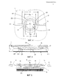
фиг. 1 - пластина со стороны рабочей зоны;FIG. 1 - plate from the side of the working area;
фиг. 2 - то же, что на фиг. 1, вид сбоку;FIG. 2 is the same as in FIG. 1, side view;
фиг. 3 - картридж, вид в изометрии;FIG. 3 - cartridge, isometric view;
фиг. 4 - конфигурация рабочей зоны, вид сверху;FIG. 4 - configuration of the working area, top view;
фиг. 5 - рабочая зона, сечение;FIG. 5 - working area, section;
фиг. 6 - картридж в рабочем состоянии.FIG. 6 - cartridge in working condition.
Картридж для проведения полимеразной цепной реакции включает плоскую пластину 1 из оптически прозрачного материала, рабочую зону 2, образованную в теле пластины 1, каналы 3 для заполнения реагентами рабочей зоны 2. Подложка 4 выполнена из алюминиевой фольги и герметично присоединена к поверхности пластины термосваркой или склеиванием.The polymerase chain reaction cartridge includes a
Рабочая зона 2 имеет форму полого цилиндра 21 диаметром D с выпуклой донной частью 22 в основании 23. Донная часть 22 образована концентрическими выточками 221, 222, 223 на боковой поверхности и ограничена плоским основанием 24. Диаметры выточек 221, 222, 223 убывают от периферии к центру и лежат в диапазоне от 0,8 D до 0,5 D; диаметр плоского основания 24 составляет 0,5 D.The
Соответственно соотношение диаметров выточек удовлетворяет условию: D>D221>D222>D223>D24, где индексы при D соответствуют позициям выточек на фиг. 3-4.Accordingly, the ratio of the diameters of the grooves satisfies the condition: D> D 221 > D 222 > D 223 > D 24 , where the indices at D correspond to the positions of the grooves in FIG. 3-4.
Глубина вдоль продольной оси 210 цилиндра 21 между донной частью 22 и плоским основанием 24 составляет от 0,28 до 0,32 Н, где Н - толщина пластины 1.The depth along the
Каналы 3 для заполнения реагентами размещены в диаметральной плоскости 210 полого цилиндра 21, выполнены в виде канавок 31 и сообщены с рабочей зоной 2 так, что их донные части 311 размещены ниже основания 23, т.е. ближе к тыльной стороне пластины на глубине h не менее 0,3Н.
Пластина 1 имеет удлиненную форму с продольной осью 11 симметрии и параллельными стенками 12 в поперечном направлении. Рабочая зона 2 размещена с одного края пластины 1 на расстоянии S=0,25-0,3 наибольшей длины пластины 1. Канавки 31 на плоскости пластины 1 имеют несквозные отверстия 32 диаметром около 3,5 мм для установки силиконовых пробок, предотвращающих вытекание жидкости из картриджа. В местах выхода канавок 31 на торцевые поверхности 13 параллельных стенок 12 образованы полукруглые фаски 14.The
Пластина 1 в направлении оси 11 имеет длину L=55 мм, ширину W=40 мм, толщину Н=2 мм, диаметр рабочей зоны составляет D=10 мм и может быть выполнена из оптически прозрачного полиметилметакрилата.The
На фиг. 6 схематично показан картридж в рабочем состоянии, где обозначены: ТЦ - поверхность термоциклера, PC - рабочая среда, В - направление подсветки для возбуждения флуресценции, Ф - анализируемый сигнал флуоресценции от рабочей среды.In FIG. Figure 6 schematically shows a cartridge in working condition, where it is indicated: TC - surface of the thermal cycler, PC - working medium, B - illumination direction for excitation of fluorescence, Ф - analyzed fluorescence signal from the working medium.
Картридж заполняют через канавки 31 рабочей средой посредством шприцев, затем в отверстия 32 устанавливают силиконовые пробки. При этом пузырьки воздуха в процессе заполнения рабочей зоны будут удаляться из нее: рабочая смесь будет эффективно выталкивать пузырьки воздуха из рабочей зоны, а ступенчатая структура - увеличивать смачиваемость вследствие развитой поверхности рабочей зоны. Исключение пузырьков воздуха необходимо для исключения их влияния на обработку результата ПЦР, так как их хаотичное перемещение и объединение вносит помехи в сигнал, тем самым искажая сигнал, получаемый при детекции флуоресценции.The cartridge is filled through the
Затем картридж устанавливают в измерительное устройство так, чтобы подложка 4 находилась в тепловом контакте с поверхностью ТЦ. Возбуждение флуоресценции осуществляют подсветкой В с торцевых поверхностей 13 стенок 12, а анализируемый сигнал Ф флуоресценции от рабочей среды PC детектируют с тыльной стороны пластины 1.Then the cartridge is installed in the measuring device so that the
Испытания показали, что технический результат в полном объеме достигается заявленной совокупностью признаков, а именно, в реакционной среде в рабочей зоне картриджа отсутствуют пузырьки воздуха. В то же время модельные эксперименты показали, что в отсутствие ступенчатой формы стенки и нерегламентированной высоты каналов в рабочей зоне образовывались пузыри воздуха, которые хаотично перемещались и укрупнялись, оказывая негативное влияние как на процесс термоциклирования, так и на детектирование флуоресценции во время проведения ПЦР.Tests have shown that the technical result is fully achieved by the claimed combination of features, namely, there are no air bubbles in the reaction medium in the working area of the cartridge. At the same time, model experiments showed that in the absence of a stepwise shape of the wall and an unregulated height of the channels in the working area, air bubbles formed that randomly moved and enlarged, having a negative effect on both the thermal cycling process and the detection of fluorescence during PCR.
Claims (7)
Priority Applications (1)
| Application Number | Priority Date | Filing Date | Title |
|---|---|---|---|
| RU2017140266A RU2658600C1 (en) | 2017-11-20 | 2017-11-20 | Construction of the cartridge working area for carrying out a polymerase chain reaction |
Applications Claiming Priority (1)
| Application Number | Priority Date | Filing Date | Title |
|---|---|---|---|
| RU2017140266A RU2658600C1 (en) | 2017-11-20 | 2017-11-20 | Construction of the cartridge working area for carrying out a polymerase chain reaction |
Publications (1)
| Publication Number | Publication Date |
|---|---|
| RU2658600C1 true RU2658600C1 (en) | 2018-06-21 |
Family
ID=62713573
Family Applications (1)
| Application Number | Title | Priority Date | Filing Date |
|---|---|---|---|
| RU2017140266A RU2658600C1 (en) | 2017-11-20 | 2017-11-20 | Construction of the cartridge working area for carrying out a polymerase chain reaction |
Country Status (1)
| Country | Link |
|---|---|
| RU (1) | RU2658600C1 (en) |
Cited By (2)
| Publication number | Priority date | Publication date | Assignee | Title |
|---|---|---|---|---|
| RU2758719C1 (en) * | 2020-12-22 | 2021-11-01 | Общество с ограниченной ответственностью «Троицкий инженерный центр» (ООО «ТИЦ») | Disposable chip cartridge for nucleic acid amplification |
| RU219829U1 (en) * | 2022-12-22 | 2023-08-09 | Федеральное государственное автономное образовательное учреждение высшего образования "Российский национальный исследовательский медицинский университет имени Н.И. Пирогова" Министерства здравоохранения Российской Федерации (ФГАОУ ВО РНИМУ им. Н.И. Пирогова Минздрава России) | DISPOSABLE MICROFLUID CARTRIDGE ANALYZER |
Citations (5)
| Publication number | Priority date | Publication date | Assignee | Title |
|---|---|---|---|---|
| US7327459B2 (en) * | 2003-12-30 | 2008-02-05 | Samsung Electronics Co., Ltd. | Fluorescence detector for detecting microfluid |
| RU2497100C2 (en) * | 2007-10-29 | 2013-10-27 | Конинклейке Филипс Электроникс Н.В. | Frustrated total internal reflection biosensor container |
| GB2516672A (en) * | 2013-07-29 | 2015-02-04 | Atlas Genetics Ltd | System and method for processing fluid in a fluidic cartridge |
| JP2016192931A (en) * | 2015-04-01 | 2016-11-17 | セイコーエプソン株式会社 | Cartridge for nucleic acid amplification reaction, and nucleic acid amplification apparatus |
| RU2628051C2 (en) * | 2009-10-19 | 2017-08-14 | Теранос, Инк. | Integrated system of collection and analysis health status information |
-
2017
- 2017-11-20 RU RU2017140266A patent/RU2658600C1/en active
Patent Citations (5)
| Publication number | Priority date | Publication date | Assignee | Title |
|---|---|---|---|---|
| US7327459B2 (en) * | 2003-12-30 | 2008-02-05 | Samsung Electronics Co., Ltd. | Fluorescence detector for detecting microfluid |
| RU2497100C2 (en) * | 2007-10-29 | 2013-10-27 | Конинклейке Филипс Электроникс Н.В. | Frustrated total internal reflection biosensor container |
| RU2628051C2 (en) * | 2009-10-19 | 2017-08-14 | Теранос, Инк. | Integrated system of collection and analysis health status information |
| GB2516672A (en) * | 2013-07-29 | 2015-02-04 | Atlas Genetics Ltd | System and method for processing fluid in a fluidic cartridge |
| JP2016192931A (en) * | 2015-04-01 | 2016-11-17 | セイコーエプソン株式会社 | Cartridge for nucleic acid amplification reaction, and nucleic acid amplification apparatus |
Cited By (2)
| Publication number | Priority date | Publication date | Assignee | Title |
|---|---|---|---|---|
| RU2758719C1 (en) * | 2020-12-22 | 2021-11-01 | Общество с ограниченной ответственностью «Троицкий инженерный центр» (ООО «ТИЦ») | Disposable chip cartridge for nucleic acid amplification |
| RU219829U1 (en) * | 2022-12-22 | 2023-08-09 | Федеральное государственное автономное образовательное учреждение высшего образования "Российский национальный исследовательский медицинский университет имени Н.И. Пирогова" Министерства здравоохранения Российской Федерации (ФГАОУ ВО РНИМУ им. Н.И. Пирогова Минздрава России) | DISPOSABLE MICROFLUID CARTRIDGE ANALYZER |
Similar Documents
| Publication | Publication Date | Title |
|---|---|---|
| US20240216915A1 (en) | Sealable microfluidic chip for thermocycling | |
| EP1792655B1 (en) | Microfluidic device comprising a bubble trap | |
| EP2163306A1 (en) | Multi-well plate with tailored chambers | |
| US12017223B2 (en) | Microfluidic device and a method of loading fluid therein | |
| US11203019B2 (en) | Method and system for temperature monitoring of a biochemical reaction vessel | |
| EP1977829A1 (en) | Device for performing multiple analyses in parallel | |
| CN103394380B (en) | A kind of high flux micro liquid sample distributor and using method | |
| US12123870B2 (en) | Fluidic system for performing assays | |
| EP1855114A1 (en) | Microchannel and microfluid chip | |
| CN112322453A (en) | Micro-fluidic chip for nucleic acid extraction, amplification and detection | |
| JP4619224B2 (en) | Rotational analysis device | |
| US20210008550A1 (en) | Microfluidic reaction vessel array with patterned films | |
| RU2658600C1 (en) | Construction of the cartridge working area for carrying out a polymerase chain reaction | |
| JP4680037B2 (en) | Fluid handling device and fluid handling unit used therefor | |
| US20090291025A1 (en) | Microchip And Method Of Using The Same | |
| JP6017793B2 (en) | Microchip | |
| Mark et al. | Aliquoting structure for centrifugal microfluidics based on a new pneumatic valve | |
| JP5070069B2 (en) | Fluid handling unit and fluid handling apparatus using the same | |
| JP6049446B2 (en) | Microchip | |
| US20230256438A1 (en) | Microfluidic cartridge | |
| RU2758719C1 (en) | Disposable chip cartridge for nucleic acid amplification | |
| JP5177514B2 (en) | Microchip | |
| JP2004358348A (en) | Precision structure | |
| CN118416970A (en) | Microfluidic cartridge | |
| JP5294200B2 (en) | Microchip |
Legal Events
| Date | Code | Title | Description |
|---|---|---|---|
| PD4A | Correction of name of patent owner |