RU2573767C1 - Three-dimensional scene scanning device with non-lambert lighting effects - Google Patents
Three-dimensional scene scanning device with non-lambert lighting effects Download PDFInfo
- Publication number
- RU2573767C1 RU2573767C1 RU2014154243/08A RU2014154243A RU2573767C1 RU 2573767 C1 RU2573767 C1 RU 2573767C1 RU 2014154243/08 A RU2014154243/08 A RU 2014154243/08A RU 2014154243 A RU2014154243 A RU 2014154243A RU 2573767 C1 RU2573767 C1 RU 2573767C1
- Authority
- RU
- Russia
- Prior art keywords
- unit
- input
- output
- template
- scene
- Prior art date
Links
- 230000000694 effects Effects 0.000 title claims abstract description 27
- 230000003044 adaptive effect Effects 0.000 claims abstract description 11
- 238000000605 extraction Methods 0.000 claims abstract description 11
- 238000005286 illumination Methods 0.000 claims abstract description 8
- 238000004364 calculation method Methods 0.000 claims description 15
- 239000000126 substance Substances 0.000 abstract description 3
- 238000003384 imaging method Methods 0.000 abstract 1
- 238000000034 method Methods 0.000 description 28
- 230000003287 optical effect Effects 0.000 description 10
- 239000000523 sample Substances 0.000 description 9
- 239000011159 matrix material Substances 0.000 description 6
- 238000012805 post-processing Methods 0.000 description 4
- 230000005855 radiation Effects 0.000 description 4
- 238000004458 analytical method Methods 0.000 description 3
- 238000000576 coating method Methods 0.000 description 3
- 238000002310 reflectometry Methods 0.000 description 3
- 239000011248 coating agent Substances 0.000 description 2
- 238000005259 measurement Methods 0.000 description 2
- 238000012546 transfer Methods 0.000 description 2
- 238000013459 approach Methods 0.000 description 1
- 230000003190 augmentative effect Effects 0.000 description 1
- 238000010276 construction Methods 0.000 description 1
- 238000010586 diagram Methods 0.000 description 1
- 238000006073 displacement reaction Methods 0.000 description 1
- 239000003814 drug Substances 0.000 description 1
- 238000005516 engineering process Methods 0.000 description 1
- 230000014509 gene expression Effects 0.000 description 1
- 238000007689 inspection Methods 0.000 description 1
- 238000012423 maintenance Methods 0.000 description 1
- 238000004519 manufacturing process Methods 0.000 description 1
- 239000000463 material Substances 0.000 description 1
- 230000005693 optoelectronics Effects 0.000 description 1
- 238000001314 profilometry Methods 0.000 description 1
- 238000000926 separation method Methods 0.000 description 1
- 230000002123 temporal effect Effects 0.000 description 1
- 238000012876 topography Methods 0.000 description 1
- 230000009466 transformation Effects 0.000 description 1
Landscapes
- Length Measuring Devices By Optical Means (AREA)
Abstract
Description
Изобретение относится к области вычислительной техники и может быть использовано в цифровых системах получения трехмерных моделей физических объектов, включая: инспекцию промышленных изделий, системы быстрого прототипирования, системы построение трехмерных моделей для виртуальной реальности и медицины.The invention relates to the field of computer technology and can be used in digital systems for obtaining three-dimensional models of physical objects, including: inspection of industrial products, rapid prototyping systems, systems for building three-dimensional models for virtual reality and medicine.
Задача трехмерной реконструкции состоит в построении математического представления геометрической информации о сцене. В большинстве существующих подходов к трехмерной реконструкции явно или неявно предполагается ламбертов закон отражающей способности каждого объекта сцены.The task of three-dimensional reconstruction is to build a mathematical representation of geometric information about the scene. In most existing approaches to three-dimensional reconstruction, the Lambert law of the reflective power of each scene object is explicitly or implicitly assumed.
На практике закон отражающей способности объектов сцены отличается от закона ламберта. Особый интерес представляют объекты с сильно неламбертовым законом рассеяния: полупрозрачные, прозрачные, зеркальные, с подповерхностными эффектами рассеяния. Отклонение от закона ламберта может быть вызвано наличием глобальных эффектов освещения внутри сцены. Яркость каждой точки сцены, воспринятой сенсором, складывается из двух составляющих освещения: прямой и глобальной. Под прямой составляющей освещения понимают свет, отразившийся от сцены лишь один раз. Глобальную составляющую освещения формирует свет, претерпевающий множественные переотражения внутри сцены.In practice, the law of the reflectivity of scene objects is different from the law of Lambert. Of particular interest are objects with a strongly non-Lambertian scattering law: translucent, transparent, mirror, with subsurface scattering effects. Deviation from the Lambert law can be caused by the presence of global lighting effects inside the scene. The brightness of each point in the scene, perceived by the sensor, consists of two components of lighting: direct and global. The direct component of lighting is understood to mean light reflected only once from the scene. The global component of lighting is formed by light undergoing multiple re-reflections within the scene.
Основная решаемая задача - построение трехмерной модели сцены с неламбертовыми эффектами освещения.The main problem to be solved is the construction of a three-dimensional model of the scene with non-Lambert lighting effects.
Решение задачи сканирования сцены с неламбертовыми эффектами освещения может быть обеспечено разделением прямой и глобальной составляющих освещения сцены и использованием шаблонов структурированного света, учитывающих особенности сканируемой сцены.The solution to the task of scanning a scene with non-Lambert lighting effects can be achieved by separating the direct and global components of the scene lighting and using structured light patterns that take into account the features of the scanned scene.
Упрощенно способы трехмерной реконструкции сцен с неламбертовыми эффектами освещения можно разделить на следующие группы:Simplified methods of three-dimensional reconstruction of scenes with non-Lambert lighting effects can be divided into the following groups:
1) способы на основе покрытия объектов с неламбертовой отражающей способностью веществом с диффузным законом отражения;1) methods based on coating objects with non-Lambert reflectivity with a substance with a diffuse reflection law;
2) способы на основе использования шаблонов высокой частоты;2) methods based on the use of high-frequency patterns;
3) способы на основе постобработки полученных данных сканирования.3) methods based on post-processing of the received scan data.
Анализ существующих способов трехмерной реконструкции показывает, что область их использования ограничена, в условиях малого объема информации о сцене. Способы на основе покрытия объектов с неламбертовой отражающей способностью веществом с диффузным законом отражения часто неприменимы ввиду значительного влияния на сканируемый объект. Живые объекты или произведения искусства не могут быть покрыты диффузным веществом без нарушения их целостности. Способы на основе использования шаблонов высокой частоты не позволяют бороться с локальными и глобальными эффектами освещения одновременно. Таким образом, может быть устранено влияние либо локальных эффектов освещения (таких как подповерхностное рассеяние), либо глобальных (вызванных многократным переотражением света внутри сцены). Способы на основе постобработки полученных данных накладывают ограничения на свойства сканируемой сцены и принципиально не позволяют восстановить утраченную в результате влияния неламбертовых эффектов освещения информацию.The analysis of existing methods of three-dimensional reconstruction shows that the scope of their use is limited, in conditions of a small amount of information about the scene. Methods based on coating objects with non-Lambert reflectivity with a substance with a diffuse reflection law are often not applicable due to the significant effect on the scanned object. Living objects or works of art cannot be coated with diffuse matter without violating their integrity. Methods based on the use of high-frequency patterns do not allow to deal with local and global lighting effects at the same time. Thus, the effect of either local lighting effects (such as subsurface scattering) or global effects (caused by multiple re-reflection of light inside the scene) can be eliminated. Methods based on post-processing of the obtained data impose restrictions on the properties of the scanned scene and fundamentally do not allow to restore the information lost as a result of the influence of non-Lambert effects of lighting.
Известен способ использования структурированного света для трехмерной реконструкции объектов, подверженных эффектам глобального освещения (Structured light for 3d shape reconstruction subject to global illumination) [Patent USA № US 8811767 B2 Aug. 19, 2014]. Изобретение относится к области построения трехмерных моделей физических объектов, и в частности к способу и системе сканирования сцен, подверженных глобальным эффектам освещения. Техническим результатом является создание усовершенствованного способа сканирования сцены с использованием структурированного света. Указанный технический результат достигается за счет того, что информация о глубине сцены получается путем проецирования множества шаблонов структурированного света на сцену. Каждый из шаблонов обладает собственной пространственной частотой, что достигается использованием различных функций кодирования; получают набор изображений сцены, содержащий одно изображение для каждой пространственной частоты; значение глубины для каждого пикселя вычисляется путем декодирования полученных наборов изображений; полученные значения глубины каждого пикселя анализируются и сохраняются, если значения глубины для различных шаблонов структурированного света совпадают; в противном случае, значение глубины будет помечено как ошибочное; анализируются ошибки, связанные с различными эффектами глобального освещения; на основе анализа определяются свойства, которыми должен обладать шаблон структурированного света, чтобы быть устойчивым к ошибкам данного рода. Эти свойства влияют на пространственную частоту шаблона, проецируемого на сцену; каждые строка и столбец пикселей проектора кодируется уникальным пространственным или временным кодом, с целью формирования шаблона структурированного света; для каждого пикселя датчика камеры соответствующие строка и столбец проектора определяются посредством декодирования измеренных значений интенсивности; дальномерная информация получается путем триангуляции лучей камеры и проектора.There is a method of using structured light for three-dimensional reconstruction of objects subject to global illumination effects (Structured light for 3d shape reconstruction subject to global illumination) [Patent USA No. US 8811767 B2 Aug. 19, 2014]. The invention relates to the field of constructing three-dimensional models of physical objects, and in particular to a method and system for scanning scenes subject to global lighting effects. The technical result is the creation of an improved method of scanning a scene using structured light. The specified technical result is achieved due to the fact that information about the depth of the scene is obtained by projecting many patterns of structured light onto the scene. Each of the templates has its own spatial frequency, which is achieved using various encoding functions; get a set of scene images containing one image for each spatial frequency; the depth value for each pixel is calculated by decoding the obtained sets of images; the obtained depth values of each pixel are analyzed and stored if the depth values for the different patterns of structured light match; otherwise, the depth value will be marked as erroneous; analyzes errors associated with various effects of global lighting; Based on the analysis, the properties that a structured light pattern must have in order to be resistant to errors of this kind are determined. These properties affect the spatial frequency of the pattern projected onto the scene; each row and column of pixels of the projector is encoded with a unique spatial or temporal code, in order to form a structured light pattern; for each pixel of the camera sensor, the corresponding row and column of the projector are determined by decoding the measured intensity values; rangefinder information is obtained by triangulating the rays of the camera and the projector.
Признаки способа-аналога, совпадающие с признаками заявляемого технического решения, следующие: позволяет построить трехмерную модель сканируемой сцены.The features of the analogue method, which coincide with the features of the claimed technical solution, are as follows: allows you to build a three-dimensional model of the scanned scene.
Недостатками известного способа являются: использование нескольких шаблонов освещения увеличивает общее время сканирования; для правильного декодирования необходимо, чтобы каждый пиксель камеры регистрировал свет лишь от одного пикселя проектора, чего сложно достичь на практике.The disadvantages of this method are: the use of several lighting patterns increases the total scanning time; For correct decoding, it is necessary that each pixel of the camera records light from only one pixel of the projector, which is difficult to achieve in practice.
Известен способ распознавания трехмерной формы объектов [Патент №2491503, МПК G01B 11/24б МПК G02B 27/22]. Способ включает освещение поверхности объекта оптическим излучением, прием и регистрацию яркости отраженного оптического излучения элементов его поверхности, преобразование оптического излучения в электрический сигнал с последующим его запоминанием и анализом. В способе используют освещение поверхности объекта коллимированными пучками оптического излучения с двух взаимно перпендикулярных направлений. Форму объекта определяют по выражениям, включающим величины видеосигналов в изображении элементов поверхности объекта с двух взаимно ортогональных направлений и наблюдении с направления, совпадающего с одним из направлений освещения; номера строк и элементов строки, для которых измеряется третья координата в изображении поверхности объекта, шаг сканирования поверхности объекта соответственно вдоль координат OY и OZ.A known method for recognizing the three-dimensional shape of objects [Patent No. 2491503, IPC G01B 11 / 24b IPC G02B 27/22]. The method includes illuminating the surface of an object with optical radiation, receiving and recording the brightness of the reflected optical radiation of the elements of its surface, converting the optical radiation into an electrical signal, followed by its storage and analysis. The method uses illumination of the surface of an object with collimated beams of optical radiation from two mutually perpendicular directions. The shape of the object is determined by the expressions, including the magnitude of the video signals in the image of the surface elements of the object from two mutually orthogonal directions and observation from a direction that coincides with one of the lighting directions; line numbers and line elements for which the third coordinate is measured in the image of the surface of the object, the scanning step of the surface of the object, respectively, along the coordinates OY and OZ.
Технический результат - устойчивость к различиям типам покрытия за счет распознавания объектов как с диффузным, так и с направленно-рассеивающим покрытием, и расширение информативности каналов оптических и оптико-электронных систем распознавания.EFFECT: resistance to differences in types of coverage due to recognition of objects with both diffuse and directionally scattering coatings, and the extension of the information content of the channels of optical and optoelectronic recognition systems.
Признаки способа-аналога, совпадающие с признаками заявляемого технического решения, следующие: позволяет построить трехмерную модель сканируемой сцены.The features of the analogue method, which coincide with the features of the claimed technical solution, are as follows: allows you to build a three-dimensional model of the scanned scene.
Недостатками известного способа являются: невозможность построения высокодетализованной модели трехмерной сцены; вычислительная сложность.The disadvantages of this method are: the inability to build a highly detailed model of a three-dimensional scene; computational complexity.
Известен способ измерения формы поверхности трехмерного объекта [Патент №2472108, МПК G01B 9/02, G01B 11/03, G01B 5/012].A known method of measuring the surface shape of a three-dimensional object [Patent No. 2472108, IPC G01B 9/02, G01B 11/03, G01B 5/012].
Изобретение относится к измерительной технике, а именно к профилометрии, топографии. Способ измерения формы поверхности трехмерного объекта заключается в использовании матрицы зондов, содержащих в верхней части жестко закрепленные светоотражательные элементы, размещенных в обойме с множеством параллельных направляющих, расположенных в узлах двумерной сетки с известными координатами Xi, Yi точек контакта каждого зонда относительно центра обоймы, позволяющих каждому зонду свободно двигаться вдоль оси Z, перпендикулярной измеряемой поверхности. Предварительно осуществляют калибровку матрицы зондов по высоте путем измерения координат Zi каждого зонда в положении контакта всех зондов с эталонной плоской гладкой поверхностью, нормаль к которой совпадает с Z направлением. При взаимном перемещении исходного трехмерного объекта и обоймы с матрицей зондов в плоскости XY измеряют координаты Xo, Yo центра обоймы и координат Zoi каждого зонда в положении контакта всех зондов с объектом, формы поверхности вычисляют на основании данных о разности указанных выше координат Xo-Xi, Yo-Yi, Zoi-Zi и повторяют измерения при необходимости. Технический результат заключается в обеспечении возможности измерения формы поверхности динамических объектов, в повышении точности измерений высоты трехмерных объектов и в уменьшении времени сканирования.The invention relates to measuring technique, namely to profilometry, topography. The method of measuring the surface shape of a three-dimensional object is to use a matrix of probes containing rigidly reflective elements in the upper part, placed in a holder with many parallel guides located in nodes of a two-dimensional grid with known coordinates X i , Y i of the contact points of each probe relative to the center of the holder, allowing each probe to move freely along the Z axis perpendicular to the measured surface. Preliminary, the probe matrix is calibrated in height by measuring the coordinates Z i of each probe in the contact position of all the probes with a reference flat smooth surface, the normal to which coincides with the Z direction. When mutual displacement starting three-dimensional object and the cage with probes matrix in the XY plane is measured coordinates X o, Y o center ring and the coordinate Z oi each probe in the contact position of the probes with the object, the surface shape is calculated based on data on the coordinate difference above X o -X i , Y o -Y i , Z oi -Z i and repeat the measurements if necessary. The technical result consists in providing the ability to measure the surface shape of dynamic objects, in improving the accuracy of measuring the height of three-dimensional objects and in reducing scan time.
Признаки способа-аналога, совпадающие с признаками заявляемого технического решения, следующие: позволяет построить трехмерную модель сканируемой сцены.The features of the analogue method, which coincide with the features of the claimed technical solution, are as follows: allows you to build a three-dimensional model of the scanned scene.
Недостатками известного способа являются: использование сложной оптической системы приводит к высокой сложности производства и обслуживания устройства; использование жестко закрепленных светоотражательных элементов приводит к невозможности изменения рабочего объема устройства.The disadvantages of this method are: the use of a complex optical system leads to high complexity of production and maintenance of the device; the use of rigidly fixed reflective elements makes it impossible to change the working volume of the device.
Наиболее близким к изобретению является способ и устройство измерения формы объекта с использованием кодированного структурированного света (Optical acquisition of object shape from coded structured light) [Patent EU № ЕР 2372648 А3]. Метод измерения формы объекта с использованием кодированного структурированного света основан на проецировании структурированного света в виде множества измерительных и одной опорной линий на объекты сцены; измерение формы объекта производится по интервалам между точками пересечений; производится захват изображения объекта с проекцией структурированного света, сгенерированного на основе данных шаблона; производится извлечение точек пересечения на захваченном изображении; производится извлечение информации о форме объекта по промежуткам между точками пересечения опорной и измерительных линий.Closest to the invention is a method and apparatus for measuring the shape of an object using coded structured light (Optical acquisition of object shape from coded structured light) [Patent EU No. EP 2372648 A3]. The method of measuring the shape of an object using coded structured light is based on projecting structured light in the form of a plurality of measurement lines and one reference line onto the objects of the scene; measuring the shape of an object is made at intervals between intersection points; capturing an image of an object with a projection of structured light generated based on template data; the intersection points on the captured image are extracted; information is extracted on the shape of the object at the intervals between the points of intersection of the reference and measuring lines.
Признаки способа и устройства его реализующего - прототипа, совпадающие с признаками заявляемого технического решения, следующие: позволяет построить трехмерную модель сканируемой сцены.The features of the method and device implementing it - the prototype, which coincide with the features of the claimed technical solution, are as follows: allows you to build a three-dimensional model of the scanned scene.
Недостатками известного способа и устройства, его реализующего, являются: невозможность работы со сценами с глобальными эффектами освещения; невозможность работы с неламбертовыми сценами: зеркальными, полупрозрачными, испытывающими эффекты подповерхностного рассеяния.The disadvantages of the known method and device that implements it are: the inability to work with scenes with global lighting effects; the impossibility of working with non-Lambert scenes: mirror, translucent, experiencing the effects of subsurface scattering.
Структурная схема устройства, реализующего рассмотренный алгоритм, содержит: блок проецирования световых шаблонов, блок генерации световых шаблонов, блок получения изображений сцены, блок извлечения шаблона из изображения сцены, блок ассоциации шаблонов, блок поиска пересекающихся областей, блок извлечения информации, блок вычисления трехмерной формы.The block diagram of a device that implements the considered algorithm contains: a block for projecting light patterns, a block for generating light patterns, a block for obtaining images of a scene, a block for extracting a pattern from a scene image, a block for associating patterns, a block for searching for overlapping areas, a block for extracting information, and a three-dimensional form calculation unit.
Предлагаемое устройство трехмерного сканирования сцены с неламбертовыми эффектами освещения позволяет получать трехмерные модели сцены в виде облака точек. Устройство реализует следующий алгоритм.The proposed device for three-dimensional scanning of a scene with non-Lambert lighting effects makes it possible to obtain three-dimensional models of the scene in the form of a point cloud. The device implements the following algorithm.
На первом шаге выполняется калибровка системы камера-проектор. Калибровка позволяет учесть искажения вносимые оптикой камеры и проектора. Калибровка камеры сводится к получению внутренних и внешних параметров камеры по имеющимся фотографиям или видео, отснятым ей. Калибровка камеры часто используется на начальном этапе решения многих задач компьютерного зрения и в особенности дополненной реальности. Кроме того, калибровка камеры помогает исправлять дисторсию на фотографиях и видео.The first step is to calibrate the camera-projector system. Calibration allows you to take into account the distortions introduced by the optics of the camera and projector. Camera calibration is reduced to obtaining the internal and external parameters of the camera from the available photos or videos captured by it. Camera calibration is often used at the initial stage of solving many tasks of computer vision and especially augmented reality. In addition, camera calibration helps correct distortion in photos and videos.
Для представления 2D-координат точки на плоскости используется вектор-столбец вида ![]()
![]()
![]()
![]()
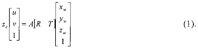
Параметры внутренней калибровкиInternal Calibration Parameters
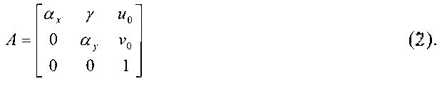
Матрица внутренней калибровки А содержит 5 значимых параметров. Эти параметры соответствуют фокусному расстоянию, углу наклона пикселей и положению принципиальной точки оптической системы. В частности, αх и αy соответствуют фокусному расстоянию, измеренному в ширине и высоте пикселя, u0 и v0 - координатам принципиальной точки, а y=αy*tanφ, где φ - угол наклона пикселя.The internal calibration matrix A contains 5 significant parameters. These parameters correspond to the focal length, the angle of the pixels, and the position of the principal point of the optical system. In particular, α x and α y correspond to the focal length measured in the width and height of the pixel, u 0 and v 0 correspond to the coordinates of the principal point, and y = α y * tanφ, where φ is the angle of the pixel.
Параметры внешней калибровки R, T (где R - вектор 3×1 или матрица 3×3 поворота, Т - вектор 3×1 переноса) - параметры внешней калибровки, определяющие преобразование координат, переводящее координаты точек сцены из мировой системы координат в систему координат, связанную с камерой.External calibration parameters R, T (where R is a 3 × 1 vector or a 3 × 3 rotation matrix, T is a 3 × 1 transfer vector) are the external calibration parameters that determine the coordinate transformation that transfers the coordinates of scene points from the world coordinate system to the coordinate system, associated with the camera.
На втором шаге производится определение оптических свойств сканируемой сцены путем разделения прямой и глобальной компонент освещения с использованием шаблонов высокой частоты. Разделение прямой и глобальной компонент освещения позволяет получить важную информацию о материалах сцены, а также улучшить эффективность методов реконструкции на основе структурированного света. Яркость It(ρ) пикселя ρ∈(x,y) в момент времени t представляет собой комбинацию прямой ![]()
![]()
![]()
![]()
![]()
![]()
![]()
![]()

Здесь st∈{0,1} - значение шаблона, спроецированного на пиксель камеры х. Положение камеры и проектора в пространстве, а также их внутренние параметры калибровки фиксированы и не зависят от геометрии сцены.Here s t ∈ {0,1} is the value of the template projected onto the camera pixel x. The position of the camera and the projector in space, as well as their internal calibration parameters, are fixed and do not depend on the geometry of the scene.
На третьем шаге производится генерация набора шаблонов структурированного света, структура которых зависит от оптических свойств сканируемой сцены. Используется временная кодировка с шаблонами переменной частоты. Двоичная кодировка состоит из последовательности двоичных образов, в которых каждый кадр представляет собой одну из битовых плоскостей двоичного представления целочисленных индексов столбцов проектора.In the third step, a set of patterns of structured light is generated, the structure of which depends on the optical properties of the scanned scene. A time coding with variable frequency patterns is used. The binary encoding consists of a sequence of binary images in which each frame represents one of the bit planes of the binary representation of the integer indices of the projector columns.
На четвертом шаге производится сканирование сцены с использованием сгенерированных шаблонов структурированного света.In the fourth step, the scene is scanned using the generated structured light patterns.
На пятом шаге производится построение трехмерной модели сцены путем триангуляции лучей камеры и проектора.At the fifth step, a three-dimensional model of the scene is constructed by triangulating the rays of the camera and the projector.
Устройство трехмерного сканирования сцены с неламбертовыми эффектами освещения (фиг. 1) содержит блок получения изображения, 1, первый вход которого является информационным входом устройства, выход которого подключен к входу блока вычисления маски глобального освещения 3 и первому входу блока извлечения шаблона 4, выход которого к первому входу блока ассоциации шаблонов 9, второму входу блока получения информации 8 и входу блока поиска пересечений 7, выход подключен к первому входу блока получения информации 8, выход которого подключен к третьему входу блока ассоциации шаблонов 9, выход которого подключен к первому входу блока вычисления трехмерной формы 10, выход которого подключен к первому входу блока хранения 12, выход которого является информационным выходом устройства; первый выход блока управления 2 подключен к второму входу блока получения изображения 1, второй выход блока управления 2 подключен к второму входу блока извлечения шаблона 4 и второму входу блока генерации адаптивных шаблонов 5, третий выход блока управления 2 подключен к второму входу блока вычисления трехмерной формы 10; выход блока вычисления маски глобального освещения 3 подключен к первому входу блока генерации адаптивных шаблонов 5, выход которого подключен к второму входу блока ассоциации шаблонов 9 и входу блока проецирования 6, выход которого подключен к второму входу блока храненения 12; синхронность работы устройства обеспечивается генератором тактовых импульсов 11.The device for three-dimensional scanning of a scene with non-Lambert lighting effects (Fig. 1) contains an image acquisition unit, 1, the first input of which is the information input of the device, the output of which is connected to the input of the global lighting mask calculation unit 3 and the first input of the template extraction unit 4, the output of which the first input of the template association unit 9, the second input of the information receiving unit 8 and the input of the intersection search unit 7, the output is connected to the first input of the information receiving unit 8, the output of which is connected to the network input of the template association unit 9, the output of which is connected to the first input of the three-dimensional shape calculation unit 10, the output of which is connected to the first input of the storage unit 12, the output of which is the information output of the device; the first output of the control unit 2 is connected to the second input of the image acquisition unit 1, the second output of the control unit 2 is connected to the second input of the template extraction unit 4 and the second input of the adaptive template generation unit 5, the third output of the control unit 2 is connected to the second input of the three-dimensional form calculation unit 10 ; the output of the global lighting mask calculation unit 3 is connected to the first input of the adaptive template generation unit 5, the output of which is connected to the second input of the template association unit 9 and the input of the projection unit 6, the output of which is connected to the second input of the storage unit 12; the synchronization of the device is provided by the clock generator 11.
Устройство трехмерной реконструкции сцен с неламбертовыми эффектами освещения работает следующим образом. С помощью блока управления 2 генерируется управляющий сигнал, поступающий на второй вход блока генерации адаптивных шаблонов 5, на выходе которого формируется шаблон для разделения локальной и глобальной составляющих освещения, поступающий на блок проецирования 6. С помощью устройства управления 2 генерируется управляющий сигнал, поступающий на второй вход блока получения изображения 1, на выходе которого формируется изображение сцены с наложенным шаблоном для разделения локальной и глобальной составляющих освещения, который поступает на блок вычисления маски глобального освещения 3, на выходе которого формируется маска глобального освещения, которая поступает на первый вход блока генерации адаптивных шаблонов 5. С помощью блока управления 3 формируется управляющий сигнал, который поступает на вход блока вычисления трехмерной формы 10, второй вход блока извлечения шаблона 4 и второй вход блока генерации адаптивных шаблонов 5. На выходе блока генерации адаптивных шаблонов 5 формируется последовательность шаблонов, полученных на основе маски глобального освещения. Сформированная последовательность шаблонов подается на вход блока проецирования 9. Осуществляется проецирование последовательности шаблонов на сцену. На вход блока получения изображений 1 поступает последовательность изображений сцены с наложенными шаблонами структурированного света. С выхода получения изображений 1 последовательность изображений сцены передается на вход блока извлечения шаблона 4, где происходит извлечение шаблонов, наложенных на сцену. На вход блока поиска пересечений и второй вход блока получения информации 8 подается результат извлечения шаблонов. В блоке поиска пересечений 7 формируется маска пересечений, которая подается на первый вход блока получения информации 8. В блоке получения информации 8 производится извлечение дальномерной информации о сцене, которая подается на третий вход блока ассоциации шаблонов 9. С выхода блока генерации адаптивных шаблонов 5 последовательность сгенерированных шаблонов поступает на второй вход блока ассоциации шаблонов 9. Извлеченные шаблоны с выхода блока извлечения шаблона 4 поступают на первый вход блока ассоциации шаблонов 9, в котором производится постобработка дальномерной информации о сцене. Результат постобработки поступает на первый вход блока вычисления трехмерной формы 10. Данные с выходов блока проецирования 6 и блока вычисления трехмерной формы 10 поступают на входы блока хранения 12, выход которого является информационным выходом устройства. Синхронность работы устройства обеспечивается генератором тактовых импульсов 11.A device for three-dimensional reconstruction of scenes with non-Lambert lighting effects works as follows. Using the control unit 2, a control signal is generated that is transmitted to the second input of the adaptive template generation unit 5, the output of which is used to generate a template for separating the local and global lighting components, which is sent to the projection unit 6. Using the control device 2, a control signal is generated that is sent to the second the input of the image acquisition unit 1, at the output of which an image of the scene with an overlay template is formed to separate the local and global components of the illumination, which is received to the calculation unit of the global lighting mask 3, at the output of which a global lighting mask is generated, which is fed to the first input of the adaptive template generation unit 5. Using the control unit 3, a control signal is generated that is input to the calculation unit of the three-dimensional shape 10, the second input of the extraction unit template 4 and the second input of the adaptive template generation unit 5. At the output of the adaptive template generation unit 5, a sequence of templates is obtained based on the global lighting mask. The generated sequence of patterns is fed to the input of the projection unit 9. The sequence of patterns is projected onto the scene. The input of the image acquisition unit 1 receives a sequence of scene images with superimposed patterns of structured light. From the output of image acquisition 1, the sequence of images of the scene is transmitted to the input of the template extraction unit 4, where the templates superimposed on the scene are extracted. The input of the intersection search block and the second input of the information obtaining unit 8 are provided with the result of the extraction of patterns. In the block of search for intersections 7, an intersection mask is formed, which is fed to the first input of the information obtaining unit 8. In the block of obtaining information 8, distance measuring information about the scene is extracted, which is fed to the third input of the block of association of patterns 9. From the output of the adaptive patterns generation block 5, the sequence of generated of templates is fed to the second input of the template association unit 9. The extracted templates from the output of the template extraction unit 4 are fed to the first input of the template association unit 9, in which GSI postprocessing rangefinder information about the scene. The result of the post-processing is fed to the first input of the three-dimensional form calculation unit 10. The data from the outputs of the projection unit 6 and the three-dimensional form calculation unit 10 are fed to the inputs of the storage unit 12, the output of which is the information output of the device. The synchronization of the device is provided by the clock generator 11.
Технический результат - получение высококачественной модели трехмерной сцены с неламбертовыми эффектами освещения.EFFECT: obtaining a high-quality model of a three-dimensional scene with non-Lambert lighting effects.
Claims (1)
Priority Applications (1)
| Application Number | Priority Date | Filing Date | Title |
|---|---|---|---|
| RU2014154243/08A RU2573767C1 (en) | 2014-12-29 | 2014-12-29 | Three-dimensional scene scanning device with non-lambert lighting effects |
Applications Claiming Priority (1)
| Application Number | Priority Date | Filing Date | Title |
|---|---|---|---|
| RU2014154243/08A RU2573767C1 (en) | 2014-12-29 | 2014-12-29 | Three-dimensional scene scanning device with non-lambert lighting effects |
Publications (1)
| Publication Number | Publication Date |
|---|---|
| RU2573767C1 true RU2573767C1 (en) | 2016-01-27 |
Family
ID=55236981
Family Applications (1)
| Application Number | Title | Priority Date | Filing Date |
|---|---|---|---|
| RU2014154243/08A RU2573767C1 (en) | 2014-12-29 | 2014-12-29 | Three-dimensional scene scanning device with non-lambert lighting effects |
Country Status (1)
| Country | Link |
|---|---|
| RU (1) | RU2573767C1 (en) |
Cited By (3)
| Publication number | Priority date | Publication date | Assignee | Title |
|---|---|---|---|---|
| RU176382U1 (en) * | 2017-08-28 | 2018-01-17 | Общество с ограниченной ответственностью "ТрансИнжКом" | INFORMATION GATHERING UNIT FOR A JOINT REALITY DEVICE |
| RU2651608C1 (en) * | 2016-12-02 | 2018-04-23 | Общество с ограниченной ответственностью "Технология" | Three-dimensional scanning device |
| RU183346U1 (en) * | 2018-03-28 | 2018-09-18 | федеральное государственное автономное образовательное учреждение высшего образования "Самарский национальный исследовательский университет имени академика С.П. Королева" | Laser-photometric device for measuring the geometric parameters of the surface of curved objects |
Citations (3)
| Publication number | Priority date | Publication date | Assignee | Title |
|---|---|---|---|---|
| EP2372648A2 (en) * | 2010-03-10 | 2011-10-05 | Canon Kabushiki Kaisha | Optical acquisition of object shape from coded structured light |
| RU2453922C2 (en) * | 2010-02-12 | 2012-06-20 | Георгий Русланович Вяхирев | Method of displaying original three-dimensional scene based on results of capturing images in two-dimensional projection |
| RU2472108C1 (en) * | 2011-08-23 | 2013-01-10 | Геннадий Николаевич Вишняков | Method of measuring 3d object surface shape |
-
2014
- 2014-12-29 RU RU2014154243/08A patent/RU2573767C1/en not_active IP Right Cessation
Patent Citations (3)
| Publication number | Priority date | Publication date | Assignee | Title |
|---|---|---|---|---|
| RU2453922C2 (en) * | 2010-02-12 | 2012-06-20 | Георгий Русланович Вяхирев | Method of displaying original three-dimensional scene based on results of capturing images in two-dimensional projection |
| EP2372648A2 (en) * | 2010-03-10 | 2011-10-05 | Canon Kabushiki Kaisha | Optical acquisition of object shape from coded structured light |
| RU2472108C1 (en) * | 2011-08-23 | 2013-01-10 | Геннадий Николаевич Вишняков | Method of measuring 3d object surface shape |
Cited By (3)
| Publication number | Priority date | Publication date | Assignee | Title |
|---|---|---|---|---|
| RU2651608C1 (en) * | 2016-12-02 | 2018-04-23 | Общество с ограниченной ответственностью "Технология" | Three-dimensional scanning device |
| RU176382U1 (en) * | 2017-08-28 | 2018-01-17 | Общество с ограниченной ответственностью "ТрансИнжКом" | INFORMATION GATHERING UNIT FOR A JOINT REALITY DEVICE |
| RU183346U1 (en) * | 2018-03-28 | 2018-09-18 | федеральное государственное автономное образовательное учреждение высшего образования "Самарский национальный исследовательский университет имени академика С.П. Королева" | Laser-photometric device for measuring the geometric parameters of the surface of curved objects |
Similar Documents
| Publication | Publication Date | Title |
|---|---|---|
| US10152800B2 (en) | Stereoscopic vision three dimensional measurement method and system for calculating laser speckle as texture | |
| CN104266587B (en) | Three-dimensional measurement system and method for obtaining actual 3D texture point cloud data | |
| US9879985B2 (en) | Simultaneous multiple view surface geometry acquisition using structured light and mirrors | |
| US20180306577A1 (en) | System and Methods for Shape Measurement Using Dual Frequency Fringe Pattern | |
| CN111047681B (en) | Single-pixel three-dimensional end-to-end reconstruction method and device based on deep learning | |
| CN105046743A (en) | Super-high-resolution three dimensional reconstruction method based on global variation technology | |
| TWI567364B (en) | Structured light generating apparatus, measuring system and method thereof | |
| CN103940370B (en) | Target object 3 D information obtaining method based on cycle relatively prime hybrid coding | |
| CN109945802A (en) | A kind of structural light three-dimensional measurement method | |
| Liao et al. | Digital image correlation assisted absolute phase unwrapping | |
| US10801834B2 (en) | Fringe projection for determining topography of a body | |
| CN105303572B (en) | Based on the main depth information acquisition method passively combined | |
| Tang et al. | An improved spatiotemporal correlation method for high-accuracy random speckle 3D reconstruction | |
| JP5761750B2 (en) | Image processing method and apparatus | |
| RU2573767C1 (en) | Three-dimensional scene scanning device with non-lambert lighting effects | |
| CN108596008A (en) | The facial jitter compensation method measured for three-dimensional face | |
| Li et al. | Monocular underwater measurement of structured light by scanning with vibrating mirrors | |
| Yu et al. | Quasi-pixelwise motion compensation for 4-step phase-shifting profilometry based on a phase error estimation | |
| CN105096314A (en) | Binary grid template-based method for obtaining structured light dynamic scene depth | |
| Wong et al. | Calibration of an array projector used for high-speed three-dimensional shape measurements using a single camera | |
| Shen et al. | Real-time 3-D measurement with dual-frequency fringes by deep learning | |
| JP2005106491A (en) | System for measuring three-dimensional shape of head part | |
| Boukamcha et al. | Robust technique for 3D shape reconstruction | |
| Juarez-Salazar et al. | Optical Fringe Projection Driving 3D Metrology Uncomplicated | |
| Shih et al. | SLResNet: Neural-Network-Based End-to-End Structure Light 3D Reconstruction for Endoscope |
Legal Events
| Date | Code | Title | Description |
|---|---|---|---|
| MM4A | The patent is invalid due to non-payment of fees |
Effective date: 20161230 |