RU2150055C1 - Liquid heating method and device for its embodiment - Google Patents
Liquid heating method and device for its embodiment Download PDFInfo
- Publication number
- RU2150055C1 RU2150055C1 RU96104366A RU96104366A RU2150055C1 RU 2150055 C1 RU2150055 C1 RU 2150055C1 RU 96104366 A RU96104366 A RU 96104366A RU 96104366 A RU96104366 A RU 96104366A RU 2150055 C1 RU2150055 C1 RU 2150055C1
- Authority
- RU
- Russia
- Prior art keywords
- impeller
- liquid
- stator
- outlet openings
- cavity
- Prior art date
Links
Images


Classifications
-
- F—MECHANICAL ENGINEERING; LIGHTING; HEATING; WEAPONS; BLASTING
- F24—HEATING; RANGES; VENTILATING
- F24C—DOMESTIC STOVES OR RANGES ; DETAILS OF DOMESTIC STOVES OR RANGES, OF GENERAL APPLICATION
- F24C9/00—Stoves or ranges heated by a single type of energy supply not covered by groups F24C3/00 - F24C7/00 or subclass F24B
-
- B—PERFORMING OPERATIONS; TRANSPORTING
- B01—PHYSICAL OR CHEMICAL PROCESSES OR APPARATUS IN GENERAL
- B01J—CHEMICAL OR PHYSICAL PROCESSES, e.g. CATALYSIS OR COLLOID CHEMISTRY; THEIR RELEVANT APPARATUS
- B01J19/00—Chemical, physical or physico-chemical processes in general; Their relevant apparatus
- B01J19/008—Processes for carrying out reactions under cavitation conditions
-
- B—PERFORMING OPERATIONS; TRANSPORTING
- B01—PHYSICAL OR CHEMICAL PROCESSES OR APPARATUS IN GENERAL
- B01J—CHEMICAL OR PHYSICAL PROCESSES, e.g. CATALYSIS OR COLLOID CHEMISTRY; THEIR RELEVANT APPARATUS
- B01J19/00—Chemical, physical or physico-chemical processes in general; Their relevant apparatus
- B01J19/18—Stationary reactors having moving elements inside
- B01J19/1806—Stationary reactors having moving elements inside resulting in a turbulent flow of the reactants, such as in centrifugal-type reactors, or having a high Reynolds-number
-
- B—PERFORMING OPERATIONS; TRANSPORTING
- B01—PHYSICAL OR CHEMICAL PROCESSES OR APPARATUS IN GENERAL
- B01J—CHEMICAL OR PHYSICAL PROCESSES, e.g. CATALYSIS OR COLLOID CHEMISTRY; THEIR RELEVANT APPARATUS
- B01J19/00—Chemical, physical or physico-chemical processes in general; Their relevant apparatus
- B01J19/18—Stationary reactors having moving elements inside
- B01J19/1887—Stationary reactors having moving elements inside forming a thin film
-
- F—MECHANICAL ENGINEERING; LIGHTING; HEATING; WEAPONS; BLASTING
- F24—HEATING; RANGES; VENTILATING
- F24V—COLLECTION, PRODUCTION OR USE OF HEAT NOT OTHERWISE PROVIDED FOR
- F24V40/00—Production or use of heat resulting from internal friction of moving fluids or from friction between fluids and moving bodies
-
- B—PERFORMING OPERATIONS; TRANSPORTING
- B01—PHYSICAL OR CHEMICAL PROCESSES OR APPARATUS IN GENERAL
- B01J—CHEMICAL OR PHYSICAL PROCESSES, e.g. CATALYSIS OR COLLOID CHEMISTRY; THEIR RELEVANT APPARATUS
- B01J2219/00—Chemical, physical or physico-chemical processes in general; Their relevant apparatus
- B01J2219/00049—Controlling or regulating processes
- B01J2219/00051—Controlling the temperature
Landscapes
- Chemical & Material Sciences (AREA)
- Engineering & Computer Science (AREA)
- Organic Chemistry (AREA)
- Chemical Kinetics & Catalysis (AREA)
- Mechanical Engineering (AREA)
- General Engineering & Computer Science (AREA)
- Combustion & Propulsion (AREA)
- Physics & Mathematics (AREA)
- Thermal Sciences (AREA)
- Life Sciences & Earth Sciences (AREA)
- Sustainable Development (AREA)
- Physical Or Chemical Processes And Apparatus (AREA)
- Lubricants (AREA)
- Exposure And Positioning Against Photoresist Photosensitive Materials (AREA)
Abstract
Description
Изобретение относится к средствам получения и использования тепла, образующегося иначе, чем в результате сгорания, и непосредственно касается способа и устройства для нагревания жидкости путем ее обработки с помощью механического воздействия. Изобретение может быть широко использовано во многих отраслях промышленности в тех многочисленных случаях, когда требуется нагревание жидкости, в частности, для целей теплофикации передвижных и относительно небольших стационарных объектов, сопутствующего нагревания жидкости при ее перекачивании, совмещенного нагревания в различных технологических процессах и т.п. The invention relates to means for producing and using heat generated differently than from combustion, and directly relates to a method and device for heating a liquid by processing it by mechanical action. The invention can be widely used in many industries in those many cases where heating of the liquid is required, in particular, for the heating of mobile and relatively small stationary objects, concomitant heating of the liquid during its pumping, combined heating in various technological processes, etc.
В технике общеизвестен эффект нагревания жидкости в результате неизбежного или сопутствующего механического воздействия на нее таких сил, как, в частности, силы трения при контактировании с вмещающей средой, силы внутреннего трения при турбулизации потока, силы, возникающие при гидравлических ударах и кавитации. Энергия, затраченная при этом на нагревание жидкости, обычно рассматривается как естественные энергетические потери. The effect of heating a fluid as a result of the inevitable or concomitant mechanical action of such forces on it as, in particular, friction forces when in contact with the surrounding medium, internal friction forces during flow turbulization, forces arising from hydraulic shock and cavitation is well known in the art. The energy expended in heating the fluid is usually regarded as natural energy loss.
Также широко известен в технике эффект нагревания жидкости в результате умышленного, но не преследующего цель нагревания, воздействия на нее механических колебаний звукового или ультразвукового диапазона. И в этом случае энергия, затраченная на нагревание жидкости, традиционно рассматривается как неизбежные энергетические потери. В частности, из уровня техники известен эффект быстрого нагревания жидкости в устройстве типа так называемой гидравлической сирены /В.И. Биглер и др. Диспергирование некоторых материалов на аппарате типа гидравлическая сирена /В сб. научных трудов N 90 Московского института стали и сплавов "Применение ультразвука в металлургии". - М.: Металлургия, 1977, с. 73-76/. Это устройство содержит рабочее колесо, имеющее полость, сообщенную с подводящим отверстием для подачи жидкости, и ряд выходных отверстий, выполненных в его периферийной кольцевой стенке, и статор, имеющий полость с отводящим отверстием для выпуска жидкости, и ряд отверстий, выполненных в его стенке, примыкающей с минимальным зазором к периферийной кольцевой стенке рабочего колеса, при этом ряды отверстий рабочего колеса и статора расположены в одной плоскости вращения. При вращении рабочего колеса жидкость, прерывисто протекающая через отверстия в нем и в статоре, подвергается воздействию вынужденных механических колебаний определенной частоты, зависящей от частоты вращения рабочего колеса и количества его выходных отверстий. Возбуждение этих колебаний в жидкости в данном случае преследовало лишь цель диспергирования материала, содержащегося в жидкости. Тем не менее авторы отметили факт аномально быстрого нагревания жидкости, который они объяснили повышенным гидравлическим сопротивлением при перетекании жидкости из полости рабочего колеса в полость статора. The effect of heating a liquid as a result of intentional, but not pursuing the purpose of heating, exposure to mechanical vibrations of the sound or ultrasound range is also widely known in the art. And in this case, the energy spent on heating the liquid is traditionally considered as inevitable energy loss. In particular, the effect of rapid heating of a liquid in a device such as a so-called hydraulic siren / B.I. is known from the prior art. Bigler et al. Dispersion of some materials on a device such as a hydraulic siren / V sb. scientific works N 90 of the Moscow Institute of Steel and Alloys "Application of ultrasound in metallurgy". - M.: Metallurgy, 1977, p. 73-76 /. This device comprises an impeller having a cavity in communication with an inlet for supplying liquid, and a series of outlet openings made in its peripheral annular wall, and a stator having a cavity with an outlet inlet for discharging liquid, and a series of openings made in its wall, adjacent with a minimum gap to the peripheral annular wall of the impeller, while the rows of holes of the impeller and the stator are located in the same plane of rotation. When the impeller rotates, the fluid flowing intermittently through the holes in it and in the stator is exposed to forced mechanical vibrations of a certain frequency, depending on the frequency of rotation of the impeller and the number of its outlet openings. The excitation of these fluctuations in the liquid in this case was only the goal of dispersing the material contained in the liquid. Nevertheless, the authors noted the fact of abnormally rapid heating of the fluid, which they explained by the increased hydraulic resistance when fluid flows from the impeller cavity to the stator cavity.
Из уровня техники известны также способ и устройство для нагревания жидкости путем ее обработки посредством механического воздействия /международная заявка N PCT/RU92/00194 от 2 ноября 1992 г. - ближайший аналог/. Они включают подачу подлежащей обработке жидкости в полость вращающегося рабочего колеса; выпуск обрабатываемой жидкости из полости рабочего колеса через ряд выходных отверстий, равномерно расположенных на его периферийной поверхности; впуск жидкости в полость статора через отверстия в его концентричной поверхности, прилегающей с минимальным зазором к периферийной поверхности рабочего колеса; при этом осуществляется периодическое резкое прерывание потока жидкости, возбуждающее механические колебания в ней. В результате такой обработки поступающая в полость статора жидкость, как установлено, нагревается в большей степени, чем это может быть объяснено суммарными гидравлическими и прочими потерями. Однако этот принципиально выявленный эффект аномального нагревания жидкости не был достаточным и стабильным для того, чтобы использовать его в практических целях с гарантированным успехом. Причина этого могла состоять в неоптимальном выборе параметров процесса, а именно частоты вращения рабочего колеса в ее взаимосвязи с его геометрическими размерами и количеством его выходных отверстий. The prior art also known a method and apparatus for heating a liquid by processing it through mechanical action / international application N PCT / RU92 / 00194 of November 2, 1992 - the closest analogue /. These include feeding the fluid to be treated into the cavity of the rotating impeller; the release of the processed fluid from the cavity of the impeller through a series of outlet openings uniformly located on its peripheral surface; fluid inlet into the stator cavity through openings in its concentric surface adjacent with a minimum clearance to the peripheral surface of the impeller; in this case, a periodic sharp interruption of the fluid flow is carried out, exciting mechanical vibrations in it. As a result of this treatment, the fluid entering the stator cavity is found to be heated to a greater extent than can be explained by the total hydraulic and other losses. However, this fundamentally revealed effect of abnormal heating of the liquid was not sufficient and stable in order to use it for practical purposes with guaranteed success. The reason for this could consist in the non-optimal choice of process parameters, namely, the frequency of rotation of the impeller in its relationship with its geometric dimensions and the number of its outlet openings.
Настоящее изобретение направлено на решение задачи создания на основе предшествующего уровня техники и собственных исследований такого способа нагревания жидкости и такого устройства для его осуществления, которые позволили бы уверенно осуществить на практике целенаправленное преобразование механической энергии в тепловую с повышенной эффективностью. The present invention is directed to solving the problem of creating, on the basis of the prior art and our own research, such a method for heating a liquid and such a device for its implementation that would allow us to confidently put into practice a targeted conversion of mechanical energy into thermal energy with increased efficiency.
Эта задача решается согласно изобретению путем обработки жидкости с помощью механического воздействия на нее процесса вращательного движения с определенной линейной скоростью на определенном радиусе вращения с наложением колебательного процесса с определенной частотой. This problem is solved according to the invention by treating a fluid by mechanically acting on it a process of rotational motion with a certain linear velocity at a certain radius of rotation with the imposition of an oscillatory process with a certain frequency.
Для этого в предлагаемом способе нагревания жидкости, как и в известном, осуществляются подача подлежащей обработке жидкости в полость вращающегося рабочего колеса; выпуск обрабатываемой жидкости из полости рабочего колеса через ряд выходных отверстий, равномерно расположенных на его периферийной поверхности; отвод жидкости по крайней мере через одно выпускное отверстие статора. Согласно основному воплощению изобретения, выпуск жидкости из полости рабочего колеса осуществляют в кольцевую камеру, образованную его периферийной поверхностью и концентрической поверхностью статора, причем радиус R периферийной поверхности рабочего колеса и частоту его вращения n задают в зависимости от выбранного количества К выходных отверстий рабочего колеса согласно эмпирическим соотношениям:
R = (1,05-1,28) К /мм/ и
n = (3,6-4,1) К-1,5•106 /об/мин/.To do this, in the proposed method for heating the liquid, as well as in the known, the liquid to be treated is supplied to the cavity of the rotating impeller; the release of the processed fluid from the cavity of the impeller through a series of outlet openings uniformly located on its peripheral surface; drainage of fluid through at least one outlet of the stator. According to the main embodiment of the invention, the discharge of fluid from the cavity of the impeller is carried out in an annular chamber formed by its peripheral surface and the concentric surface of the stator, the radius R of the peripheral surface of the impeller and its rotation frequency n being set depending on the selected number K of the outlet openings of the impeller according to empirical to the ratios:
R = (1.05-1.28) K / mm / and
n = (3.6-4.1) K -1.5 • 10 6 / rpm /.
За пределами указанных диапазонов параметров достигаемый эффект аномального нагревания жидкости, как установлено экспериментально, выражается в недостаточной степени. Outside the specified ranges of parameters, the achieved effect of abnormal heating of the liquid, as established experimentally, is not sufficiently expressed.
В наиболее предпочтительном воплощении способа нагревания жидкости радиус R и частоту вращения n рабочего колеса номинально задают в зависимости от выбранного количества К его выходных отверстий согласно эмпирическим соотношениям:
R = 1,1614 К /мм/ и
n = 3,8396 К-1,5•106 /об/мин/.In the most preferred embodiment of the method of heating the liquid, the radius R and the rotational speed n of the impeller are nominally set depending on the selected number K of its outlet openings according to empirical relations:
R = 1.1614 K / mm / s
n = 3.8396 K -1.5 • 10 6 / rpm /.
В другом предпочтительном воплощении способа нагревания жидкости отвод обрабатываемой жидкости из кольцевой камеры, образованной периферийной поверхностью рабочего колеса и концентричной поверхностью статора, осуществляют через ряд выпускных отверстий, равномерно расположенных на концентричной поверхности статора, которые при вращении рабочего колеса последовательно располагаются против его выходных отверстий. In another preferred embodiment of the method of heating the liquid, the liquid to be processed is withdrawn from the annular chamber formed by the peripheral surface of the impeller and the concentric surface of the stator through a series of outlet openings uniformly located on the concentric surface of the stator, which are rotated in series against the outlet openings.
В описанном основном воплощении способа нагревания жидкости при указанных диапазонах выбора параметров R и n принципиально достигается такая температура нагревания жидкости, которая, как установлено экспериментально, превышает температуру, достижимую лишь вследствие гидравлических и иных потерь, в такой мере и с такой стабильностью, что позволительно говорить о целенаправленном и достаточно эффективном использовании такого способа нагревания жидкости в практических целях. Возникающий позитивный итог баланса энергии можно объяснить, не претендуя на исчерпывающие полноту и точность и имея в виду закон сохранения энергии, высвобождением потенциальной энергии внутренних связей жидкости на молекулярном уровне в результате периодического инициирующего по существу механического воздействия на жидкость на определенных критических частотах и их гармониках. In the described main embodiment of the method of heating the liquid at the indicated ranges of the choice of the parameters R and n, a temperature of heating the liquid is reached in principle, which, as established experimentally, exceeds the temperature attainable only due to hydraulic and other losses, to such an extent and with such stability that it is possible to speak about purposeful and quite effective use of such a method of heating a liquid for practical purposes. The resulting positive result of the energy balance can be explained without pretending to exhaustive completeness and accuracy and bearing in mind the law of conservation of energy, the release of the potential energy of the internal bonds of the liquid at the molecular level as a result of a periodically initiating essentially mechanical effect on the liquid at certain critical frequencies and their harmonics.
В наиболее предпочтительном воплощении способа нагревания жидкости при выборе указанных номинальных величин параметров R и n, установленных экспериментально, эффект избыточного баланса энергии проявляется наиболее сильно. Другое предпочтительное воплощение способа нагревания жидкости позволяет улучшить достигаемый эффект благодаря комбинированному колебательному воздействию на жидкость сначала при ее выходе через отверстия рабочего колеса в кольцевую камеру, а затем при ее выходе из кольцевой камеры через отверстия на концентричной поверхности статора. In the most preferred embodiment of the method of heating the liquid when choosing the indicated nominal values of the parameters R and n established experimentally, the effect of the excess energy balance is most pronounced. Another preferred embodiment of the method of heating the liquid allows to improve the effect due to the combined oscillatory action on the liquid, first when it exits through the openings of the impeller into the annular chamber, and then when it exits the annular chamber through the openings on the concentric surface of the stator.
Способ нагревания жидкости согласно изобретению может быть осуществлен только с помощью описанного ниже устройства, которое составляет неотъемлемую часть общего изобретательского замысла. The method of heating a liquid according to the invention can only be carried out using the device described below, which is an integral part of the general inventive concept.
Устройство для нагревания жидкости, как и известное, содержит ротор, включающий установленный в подшипниках вал и по крайней мере одно соединенное с валом рабочее колесо, выполненное в виде диска с периферийной кольцевой стенкой, в которой выполнен ряд выходных отверстий для жидкости, равномерно распределенных по окружности; статор с концентричной рабочему колесу стенкой, впускным отверстием для подачи жидкости, сообщенным с полостью рабочего колеса, и по крайней мере одним выпускным отверстием для отвода жидкости; средство для привода ротора с расчетной частотой вращения. Согласно основному воплощению изобретения, концентричная стенка статора образует вместе с периферийной кольцевой стенкой рабочего колеса кольцевую камеру, сообщенную по крайней мере с одним отверстием для отвода жидкости, причем радиус R внешней поверхности периферийной кольцевой стенки рабочего колеса составляет
R = (1,05-1,28) K /мм/
где К - выбранное количество выходных отверстий рабочего колеса, а радиальный размер ΔR кольцевой камеры составляет
Δ R = (1,05-1,28) В /мм/,
где B - выбранное целое число в интервале 1-K/2.A device for heating a liquid, as known, contains a rotor including a shaft installed in the bearings and at least one impeller connected to the shaft, made in the form of a disk with a peripheral annular wall, in which a number of liquid outlets are made uniformly distributed around the circumference ; a stator with a concentric impeller wall, an inlet for supplying fluid in communication with the cavity of the impeller, and at least one outlet for discharging fluid; means for driving a rotor with a design speed. According to the main embodiment of the invention, the concentric wall of the stator forms, together with the peripheral annular wall of the impeller, an annular chamber in communication with at least one fluid outlet, the radius R of the outer surface of the peripheral annular wall of the impeller being
R = (1.05-1.28) K / mm /
where K is the selected number of outlet openings of the impeller, and the radial size ΔR of the annular chamber is
Δ R = (1.05-1.28) V / mm /,
where B is the selected integer in the range 1-K / 2.
В наиболее предпочтительном воплощении устройства для нагревания жидкости радиус R внешней поверхности периферийной кольцевой стенки рабочего колеса номинально составляет
R = 1,1614 К /мм/,
где К - выбранное количество выходных отверстий рабочего колеса, а радиальный размер Δ R кольцевой камеры номинально составляет
Δ R = 1,1614 К /мм/,
где B - выбранное целое число в интервале 1-K/5.In a most preferred embodiment of a device for heating a liquid, the radius R of the outer surface of the peripheral annular wall of the impeller is nominally
R = 1.1614 K / mm /,
where K is the selected number of outlet openings of the impeller, and the radial size Δ R of the annular chamber is nominally
Δ R = 1.1614 K / mm /,
where B is the selected integer in the range 1-K / 5.
В другом предпочтительном воплощении устройства для нагревания жидкости статор имеет полость для приема жидкости из кольцевой камеры, сообщенную с выпускным отверстием для ее отвода, а в концентричной стенке статора равномерно по окружности в плоскости расположения выходных отверстий рабочего колеса выполнен ряд выпускных отверстий, сообщающих полость статора с кольцевой камерой, количество которых составляет 1-K. In another preferred embodiment of the device for heating the fluid, the stator has a cavity for receiving fluid from the annular chamber, in communication with the outlet for its discharge, and a number of outlets are made in the concentric wall of the stator uniformly around the circumference in the plane of the outlet openings of the impeller, communicating with the stator cavity annular chamber, the number of which is 1-K.
Более подробно изобретение поясняется ниже на примерах его практического осуществления, иллюстрируемых схематическими чертежами, на которых представлены:
фиг. 1 - продольный осевой разрез устройства для нагревания жидкости в основном и наиболее предпочтительном воплощениях;
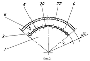
фиг. 2, 4 - частичный поперечный разрез кольцевой камеры;
фиг. 3 - продольный осевой разрез устройства для нагревания жидкости в одном из предпочтительных воплощений.In more detail, the invention is illustrated below by examples of its practical implementation, illustrated by schematic drawings, on which are presented:
FIG. 1 is a longitudinal axial section through a device for heating a liquid in the main and most preferred embodiments;
FIG. 2, 4 - a partial cross section of the annular chamber;
FIG. 3 is a longitudinal axial section through a device for heating a liquid in one of the preferred embodiments.
Согласно основному воплощению /фиг. 1, 2/ способа нагревания жидкости путем ее обработки с помощью механического воздействия, подлежащая обработке жидкость подается в полость 1 вращающегося рабочего колеса 2 через входное отверстие 3. Во время вращения рабочего колеса 2 обрабатываемая жидкость выпускается из его полости 1 в кольцевую камеру 4, образованную периферийной цилиндрической поверхностью 5 рабочего колеса 2 и концентричной поверхностью 6 статора 7, через ряд выходных отверстий 8, расположенных на периферийной поверхности 5 рабочего колеса 2 и равномерно распределенных по окружности. В пределах кольцевой камеры 4 обрабатываемая жидкость, продолжая вращение относительно центральной оси 9 по закону свободного потока, подвергается воздействию механических колебаний, обусловленных взаимодействием с концентричной поверхностью 6 статора 7 элементарных потоков жидкости, истекающих из каждого выходного отверстия 8 рабочего колеса 2. Обработанная жидкость отводится из кольцевой камеры 4 через выпускное отверстие 10. According to the main embodiment / FIG. 1, 2 / of a method for heating a liquid by processing it by mechanical action, the liquid to be treated is fed into the
Радиус R периферийной поверхности 5 и частота вращения n рабочего колеса 2 определяются выбранным количеством К его выходных отверстий 8 в диапазоне согласно следующим эмпирическим соотношениям:
R = (1,05-1,28) K /мм/ и
n = (3,6-4,1) K-1,5•106 /об/мин/.The radius R of the
R = (1.05-1.28) K / mm / and
n = (3.6-4.1) K -1.5 • 10 6 / rpm /.
Согласно наиболее предпочтительному способу нагревания жидкости /фиг. 1, 2/, радиус R и частота вращения n рабочего колеса 2 номинально определяются выбранным количеством К его выходных отверстий согласно эмпирическим соотношениям:
R= 1,1614 K /мм/ и
n = 3,8396 K-1,5•106 /об/мин/.According to the most preferred method of heating the liquid / FIG. 1, 2 /, the radius R and the rotational speed n of the
R = 1.1614 K / mm / and
n = 3.8396 K -1.5 • 10 6 / rpm /.
Согласно другому предпочтительному воплощению /фиг. 3, 4/ способа нагревания жидкости, отвод обрабатываемой жидкости из кольцевой камеры 4, образованной периферийной поверхностью 5 рабочего колеса 2 и концентричной поверхностью 6 статора 7, осуществляется через одно, несколько или ряд выпускных отверстий 11 на концентричной поверхности 6 статора 7. Эти выпускные отверстия 11 кольцевой камеры 4 при вращении рабочего колеса 2 последовательно располагаются против его выходных отверстий 8, вызывая периодические возмущения потока и соответствующие механические колебания в жидкости со звуковой частотой. Прошедшая через выпускные отверстия 11 кольцевой камеры 4 жидкость поступает в полость 12 статора 7, откуда она отводится через выпускное отверстие 13. According to another preferred embodiment / FIG. 3, 4 / of the method of heating the liquid, the discharge of the processed liquid from the
Количество выпускных отверстий 11 кольцевой камеры 4 выбирается в пределах от одного до К, при этом учитывается, что с увеличением количества выпускных отверстий 11 при прочих равных условиях адекватно повышается объемная производительность процесса, но уменьшается температура нагрева жидкости. The number of
Согласно основному воплощению /фиг. 1, 2/ устройства для осуществления описанного способа нагревания жидкости, оно содержит ротор 14, включающий вал 15, установленный в подшипниках 16 и 17 и снабженный уплотнением 18 Ротор 14 содержит по крайней мере одно рабочее колесо 2, соединенное с валом 15 и выполненное в виде диска 19 с периферийной кольцевой стенкой 20, имеющей цилиндрическую внешнюю поверхность 5. В этой стенке 20 выполнен ряд выходных отверстий 8 для жидкости, равномерно распределенных по окружности. According to the main embodiment / FIG. 1, 2 / of a device for implementing the described method of heating a liquid, it comprises a
Статор 7, вмещающий рабочее колесо 2, имеет впускное отверстие 3 для подачи жидкости на обработку и выпускное отверстие 10 для отвода обработанной жидкости. Полость 1 рабочего колеса 2 для приема подлежащей обработке жидкости образована диском 19 и кольцевой стенкой 20 рабочего колеса 2, а также в данном случае примыкающей к нему стенкой 21 статора 7 с впускным отверстием 3. Кольцевая камера 4 для приема обрабатываемой жидкости ограничена в радиальном направлении кольцевой стенкой 20 рабочего колеса 2 и концентричной стенкой 22 статора 7 и сообщена с выпускным отверстием 10 для отвода обработанной жидкости. The
Характерные геометрические размеры рабочего колеса 2 и кольцевой камеры 4 составляют:
R = (1,05-1,28) К /мм/ и
Δ R = (1,05-1,28) В /мм/,
где K - выбранное количество выходных отверстий 8 рабочего колеса 2,
R - радиус внешней поверхности 5 периферийной кольцевой стенки 20 рабочего колеса 2,
B - выбранное целое число в интервале 1-К/2,
Δ R - радиальный размер кольцевой камеры 4.The characteristic geometric dimensions of the
R = (1.05-1.28) K / mm / and
Δ R = (1.05-1.28) V / mm /,
where K is the selected number of
R is the radius of the
B is the selected integer in the range 1-K / 2,
Δ R is the radial size of the
В наиболее предпочтительном воплощении /фиг. 1, 2/ устройства для нагревания жидкости номинальная величина радиуса R составляет
R = 1,1614 К /мм/,
а номинальный радиальный размер R составляет
Δ R = 1,1614 В /мм/,
где B - выбранное целое число в интервале 1-К/5.In the most preferred embodiment / FIG. 1, 2 / device for heating the liquid, the nominal value of the radius R is
R = 1.1614 K / mm /,
and the nominal radial size R is
Δ R = 1.1614 V / mm /,
where B is the selected integer in the range 1-K / 5.
Согласно другому предпочтительному воплощению /фиг. 3, 4/ устройства для нагревания жидкости, статор 7 имеет полость 12, примыкающую к его концентричной стенке 22, для приема жидкости из кольцевой камеры 4, сообщенную с выпускным отверстием 13 для отвода обработанной жидкости. Полость 12 статора 7 сообщена с кольцевой камерой 4 выпускными отверстиями 11 для выпуска жидкости из кольцевой камеры 4 и одновременно для ее впуска в полость 12 статора 7, выполненными в концентричной стенке 22 статора 7. Эти выпускные отверстия 11 находятся в плоскости расположения ряда выходных отверстий 8 рабочего колеса 2 и равномерно распределены по окружности. Количество отверстий 11 составляет от одного до K, причем их количество, большее K, нецелесообразно ввиду заметного снижения, при прочих равных условиях, теплового эффекта. According to another preferred embodiment / FIG. 3, 4 / of the device for heating the liquid, the
Ротор 14 соединен посредством вала 15 и муфты 23 со средством для его привода с расчетной частотой вращения, например, с электродвигателем 24. The
Ротор может содержать несколько рабочих колес, установленных на одном валу, которые по потоку жидкости соединены последовательно. Каждое рабочее колесо может быть снабжено лопатками. The rotor may contain several impellers mounted on one shaft, which are connected in series with the fluid flow. Each impeller can be equipped with blades.
Приведение рабочего колеса во вращение может осуществляться как от специально предназначенного для этих целей двигателя /электрического, гидравлического, механического, ветрового и др./, так и от подвижных и в особенности вращающихся частей транспортных средств /железнодорожных вагонов и т. п./. Bringing the impeller into rotation can be carried out both from a specially designed engine for this purpose / electric, hydraulic, mechanical, wind, etc. /, as well as from moving and in particular rotating parts of vehicles / railway cars, etc. /.
Может быть предусмотрен как внутренний, так и внешний перепускной канал с запорно-регулирующим органом для обратной подачи части обработанной жидкости с выхода устройства на его вход на повторную обработку. Both an internal and external bypass channel with a shut-off and regulating body can be provided for the reverse supply of part of the treated liquid from the output of the device to its entrance to the reprocessing.
Устройство в целом может занимать любое пространственное положение. The device as a whole can occupy any spatial position.
Количество К выходных отверстий 8 рабочего колеса 2 выбирается исходя из желаемой частоты F вынужденных колебаний, возбуждаемых в жидкости в звуковом диапазоне, которая определяется эмпирическим соотношением
F = 63,993 K-0,5 /кГц/,
с учетом достижимых и целесообразных геометрических размеров устройства в целом.The number K of the
F = 63.993 K -0.5 / kHz /,
taking into account the achievable and appropriate geometric dimensions of the device as a whole.
Величина B выбирается в указанных выше пределах в зависимости от физических свойств конкретной обрабатываемой жидкости, в особенности от ее вязкости и характера изменения вязкости при нагревании, с учетом приемлемых геометрических размеров установки в целом. The value of B is selected within the above ranges depending on the physical properties of the particular fluid being treated, in particular on its viscosity and the nature of the viscosity change when heated, taking into account the acceptable geometric dimensions of the installation as a whole.
Перечень видов обрабатываемой жидкости весьма обширен - это собственно жидкости от воды до углеводородных и кремнийорганических жидкостей, а также всевозможные растворы, эмульсии и суспензии на их основе, в широком диапазоне вязкости и других физико-химических свойств. The list of types of processed fluid is very extensive - it is actually liquids from water to hydrocarbon and organosilicon liquids, as well as all kinds of solutions, emulsions and suspensions based on them, in a wide range of viscosity and other physicochemical properties.
Выбор количества отверстий 11 для выпуска жидкости из кольцевой камеры 4 производится в зависимости от желаемого соотношения объемной производительности устройства и температуры нагрева жидкости. The choice of the number of
Ширина отверстий 8 рабочего колеса 2 в окружном направлении на его периферийной поверхности 5 предпочтительно составляет половину их окружного шага на окружности радиуса R. Ширина выпускных отверстий 11 кольцевой камеры 4 в окружном направлении на ее концентричной поверхности 6, независимо от их количества, предпочтительно не должна превышать ширины выходных отверстий 8. Предпочтительна одинаковая, вытянутая в направлении, параллельном центральной оси 9, форма отверстий 8 и 11, как схематически изображено на фиг. 3. The width of the
Устройство для нагревания жидкости согласно изобретению работает следующим образом. A device for heating a liquid according to the invention operates as follows.
В основном и наиболее предпочтительном воплощениях устройства /фиг. 1, 2/ обрабатываемая жидкость подается через впускное отверстие 3 в полость 1 рабочего колеса 2 в направлении, показанном стрелкой. Ротор 14 вместе с рабочим колесом 2 приводится во вращение с помощью электродвигателя 24 через муфту 23 и вал 15 с расчетной частотой вращения n. При этом поступающая в полость 1 рабочего колеса 2 жидкость под давлением выходит из полости 1 через ряд выходных отверстий 8 в периферийной кольцевой стенке 20 рабочего колеса 2, поступая в кольцевую камеру 4, ограниченную кольцевой стенкой 20 рабочего колеса 2 и концентричной стенкой 22 статора 7. Из кольцевой камеры 4 обработанная жидкость отводится для потребления, использования или дальнейшей обработки через выпускное отверстие 10 статора 7 в направлении, показанном стрелкой. In the main and most preferred embodiments of the device / Fig. 1, 2 / the liquid to be treated is supplied through the
В другом предпочтительном воплощении устройство /фиг. 3,4/ работает аналогично вышеописанному, за тем исключением, что из кольцевой камеры 4 обрабатываемая жидкость выходит в полость 12 статора 7 через ряд выпускных отверстий 11 в концентричной стенке 22 статора 7. Из полости 12 обработанная жидкость отводится для потребления, использования или дальнейшей обработки через выпускное отверстие 13 статора 7 в направлении, показанном стрелкой. In another preferred embodiment, the device / FIG. 3.4 / works in the same way as described above, except that from the
Ниже приведены конкретные примеры практической реализации соответствующих изобретению способа нагревания жидкости и устройства для его осуществления /см. таблиц 1 и 2/. The following are specific examples of the practical implementation of the method of heating a liquid and a device for its implementation / cm according to the invention. tables 1 and 2 /.
Claims (6)
R = (1,05 - 1,28)К (мм) и
n = (3,6 - 4,1) К-1,5 • 106 (об/мин).1. A method of heating a liquid by processing it by mechanical action, comprising supplying the liquid to be treated into the cavity of a rotating impeller, discharging the liquid to be processed from the cavity of the impeller through a series of outlet openings uniformly located on its peripheral surface, and draining the liquid through at least one stator outlet, characterized in that the discharge of fluid from the cavity of the impeller is carried out in an annular chamber formed by its peripheral surface and con entrichnoy stator surface, the radius R of the impeller peripheral face and its rotation frequency n is set depending on selected number K of the impeller exit holes according to empirical relationships
R = (1.05 - 1.28) K (mm) and
n = (3.6 - 4.1) K -1.5 • 10 6 (rpm).
R = 1,1614 К (мм) и
n = 3,8396 К-1,5 • 106 (об/мин).2. The method according to claim 1, characterized in that the parameters R and n are nominally set depending on the parameter K according to empirical relations
R = 1.1614 K (mm) and
n = 3.8396 K -1.5 • 10 6 (rpm).
R = (1,05 - 1,28) К (мм),
где К - выбранное количество выходных отверстий рабочего колеса, а радиальный размер ΔR кольцевой камеры составляет
ΔR = (1,05 - 1,28) В (мм),
где В - выбранное целое число в интервале 1 - К/2.4. A device for heating a liquid by machining it by mechanical action, which comprises a rotor including a shaft mounted in bearings and at least one impeller connected to the shaft in the form of a disk with a peripheral annular wall in which a number of liquid outlet openings are provided, evenly distributed around a circle; a stator having a wall concentric with the impeller, an inlet for supplying fluid in communication with the cavity of the impeller, and at least one outlet for discharging fluid; means for driving a rotor with an estimated rotational speed, characterized in that the concentric wall of the stator forms, together with the peripheral annular wall of the impeller, an annular chamber in communication with at least one outlet for discharging liquid, the radius R of the outer surface of the peripheral annular wall of the impeller being
R = (1.05 - 1.28) K (mm),
where K is the selected number of outlet openings of the impeller, and the radial size ΔR of the annular chamber is
ΔR = (1.05 - 1.28) V (mm),
where B is the selected integer in the range 1 - K / 2.
R = 1,1614 К (мм),
где К - выбранное количество выходных отверстий рабочего колеса, а радиальный размер ΔR кольцевой камеры номинально составляет
ΔR = 1,1614 В (мм),
где В - выбранное целое число в интервале 1 - К/5.5. The device according to claim 4, characterized in that the radius R of the outer surface of the peripheral annular wall of the impeller is nominally
R = 1.1614 K (mm),
where K is the selected number of impeller outlet openings, and the radial size ΔR of the annular chamber is nominally
ΔR = 1.1614 V (mm),
where B is the selected integer in the range 1 - K / 5.
Applications Claiming Priority (1)
| Application Number | Priority Date | Filing Date | Title |
|---|---|---|---|
| PCT/RU1995/000070 WO1996033374A1 (en) | 1995-04-18 | 1995-04-18 | Method of heating a liquid and a device therefor |
Related Child Applications (1)
| Application Number | Title | Priority Date | Filing Date |
|---|---|---|---|
| RU99106668/06A Division RU99106668A (en) | 1995-04-18 | 1999-03-25 | METHOD FOR LIQUID HEATING AND DEVICE FOR ITS IMPLEMENTATION |
Publications (2)
| Publication Number | Publication Date |
|---|---|
| RU96104366A RU96104366A (en) | 1998-04-27 |
| RU2150055C1 true RU2150055C1 (en) | 2000-05-27 |
Family
ID=20129918
Family Applications (1)
| Application Number | Title | Priority Date | Filing Date |
|---|---|---|---|
| RU96104366A RU2150055C1 (en) | 1995-04-18 | 1995-04-18 | Liquid heating method and device for its embodiment |
Country Status (5)
| Country | Link |
|---|---|
| US (2) | US6016798A (en) |
| EP (1) | EP0833114A4 (en) |
| JP (1) | JPH11503818A (en) |
| RU (1) | RU2150055C1 (en) |
| WO (1) | WO1996033374A1 (en) |
Cited By (2)
| Publication number | Priority date | Publication date | Assignee | Title |
|---|---|---|---|---|
| CN105066441A (en) * | 2015-07-22 | 2015-11-18 | 林钧浩 | High-temperature warm air machine achieving heat generation through convection |
| WO2018139948A1 (en) * | 2017-01-27 | 2018-08-02 | Марат Отеллович ЯРИМОВ | Method for generating thermal energy (variants) and device for the implementation thereof |
Families Citing this family (34)
| Publication number | Priority date | Publication date | Assignee | Title |
|---|---|---|---|---|
| EP0826416A4 (en) * | 1995-04-18 | 1998-06-10 | Nikolai Ivanovich Selivanov | Method of conditioning hydrocarbon liquids and an apparatus for carrying out the method |
| JP3460454B2 (en) * | 1996-07-15 | 2003-10-27 | 株式会社豊田自動織機 | Viscous heater |
| US6783271B1 (en) * | 1999-08-24 | 2004-08-31 | Zakrytoe Aktsionernoe Obschestvo “Katalizatornaya Kompaniya” | Rotary dispergator, method of producing food products with the use thereof and food products produced by this method |
| AU2002323850A1 (en) * | 2002-05-06 | 2003-11-17 | Nikolay Ivanovich Selivanov | Method for resonance excitation of liquid and device for heating liquid |
| EP1538404A1 (en) * | 2003-12-03 | 2005-06-08 | Optos Optimale Oszillationstechnik GmbH | System and method for heating an object |
| US7736521B2 (en) * | 2004-03-15 | 2010-06-15 | Total Separation Solutions, Llc | Viscosity control and filtration of well fluids |
| US7201225B2 (en) * | 2005-02-14 | 2007-04-10 | Total Separation Solutions, Llc | Conserving components of fluids |
| US7546874B2 (en) | 2005-02-14 | 2009-06-16 | Total Separation Solutions, Llc | Conserving components of fluids |
| WO2006125422A1 (en) * | 2005-05-22 | 2006-11-30 | Ip2H Ag | Method for processing a chemical substance |
| US20130075245A1 (en) | 2009-12-16 | 2013-03-28 | F. Alan Frick | Methods and systems for heating and manipulating fluids |
| US8371251B2 (en) * | 2006-04-24 | 2013-02-12 | Phoenix Caliente Llc | Methods and apparatuses for heating, concentrating and evaporating fluid |
| US7614367B1 (en) | 2006-05-15 | 2009-11-10 | F. Alan Frick | Method and apparatus for heating, concentrating and evaporating fluid |
| US10039996B2 (en) | 2006-04-24 | 2018-08-07 | Phoenix Callente LLC | Methods and systems for heating and manipulating fluids |
| ATE435404T1 (en) * | 2006-05-06 | 2009-07-15 | Kakimzhan Utkilbayev | TURBINE HEAT GENERATOR |
| US7767159B2 (en) * | 2007-03-29 | 2010-08-03 | Victor Nikolaevich Glotov | Continuous flow sonic reactor and method |
| GB0901954D0 (en) * | 2009-02-09 | 2009-03-11 | Unilever Plc | Improvments relating to mixing apparatus |
| GB0901956D0 (en) * | 2009-02-09 | 2009-03-11 | Unilever Plc | Improvements relating to mixing apparatus |
| US20100296365A1 (en) * | 2009-05-22 | 2010-11-25 | Bolobolichev Alexander | Apparatus for treatment of liquids |
| ITVI20090215A1 (en) * | 2009-08-11 | 2011-02-12 | Fontana Roberto | ELECTRIC MACHINE FOR FLUID HEATING |
| SG184459A1 (en) * | 2010-04-14 | 2012-11-29 | Pristec Ag | Method for the treatment of a liquid, in particular a mineral oil |
| HU230503B1 (en) | 2011-05-27 | 2016-09-28 | Technobazalt S.R.O | Cavitation boiler |
| US8401764B2 (en) | 2012-01-18 | 2013-03-19 | Ford Global Technologies, Llc | Fuel identification based on crankshaft acceleration |
| US9339785B2 (en) | 2013-12-18 | 2016-05-17 | Battelle Memorial Institute | Methods and systems for acoustically-assisted hydroprocessing at low pressure |
| US20150260432A1 (en) | 2014-03-11 | 2015-09-17 | US Intercorp LLC | Method and apparatus for heating liquids |
| US20170130954A1 (en) | 2014-03-11 | 2017-05-11 | US Intercorp LLC | Method and apparatus for heating and purifying liquids |
| US9827540B2 (en) | 2014-05-19 | 2017-11-28 | Highland Fluid Technology, Ltd. | Central entry dual rotor cavitation |
| KR101584754B1 (en) * | 2015-05-13 | 2016-01-12 | 이영택 | Apparatus for supplying hot-water |
| US20170306982A1 (en) * | 2016-04-20 | 2017-10-26 | HST Asset Holdings LLC | Split Casing Cavitation Generator |
| WO2018132640A1 (en) | 2017-01-13 | 2018-07-19 | US Intercorp LLC | Method and apparatus for heating and purifying liquids |
| CN111093821B (en) * | 2017-06-14 | 2023-06-27 | 自然资源选矿有限公司 | Method for generating a parametric resonance of energy in atoms of a chemical element in a substance |
| RU2650972C1 (en) * | 2017-10-02 | 2018-04-18 | Андрей Владиславович Курочкин | Device for vacuum deaeration (variants) |
| WO2019221726A1 (en) | 2018-05-16 | 2019-11-21 | Dresser-Rand Company | Turbomachine chemical reactor and method for cracking hydrocarbons in a process fluid |
| US11123702B2 (en) | 2018-09-20 | 2021-09-21 | Dresser-Rand Company | Turbomachine type chemical reactor |
| US12103868B2 (en) | 2021-01-27 | 2024-10-01 | Shockwater Solutions, LLC | Process and apparatus for multi-phase reaction processing of liquids |
Family Cites Families (71)
| Publication number | Priority date | Publication date | Assignee | Title |
|---|---|---|---|---|
| US1790967A (en) * | 1931-02-03 | auerbach | ||
| US797847A (en) * | 1902-05-24 | 1905-08-22 | Frank J Gilroy | Heating fluids mechanically. |
| US823856A (en) * | 1903-03-18 | 1906-06-19 | Frank J Gilroy | Heating fluids mechanically. |
| US1338996A (en) * | 1919-11-12 | 1920-05-04 | Collen E Norcross | Method of and apparatus for emulsification |
| US1382765A (en) * | 1920-01-03 | 1921-06-28 | Sharples Separator Co | Emulsifier |
| GB191472A (en) * | 1921-10-12 | 1923-01-12 | William Douglas & Sons Ltd | Improvements in or relating to the production of emulsions |
| US1489786A (en) * | 1923-08-03 | 1924-04-08 | Povey Harry | Machine for disintegrating and emulsifying materials |
| US1489787A (en) * | 1923-11-30 | 1924-04-08 | Povey Harry | Machine for disintegrating or emulsifying materials |
| US1890106A (en) * | 1930-11-24 | 1932-12-06 | J C Vredenburg | Apparatus for emulsification of immiscible ingredients |
| US1873037A (en) * | 1931-08-15 | 1932-08-23 | Sinclair Refining Co | Art of cracking hydrocarbons |
| US2009957A (en) * | 1933-06-13 | 1935-07-30 | Texas Co | Emulsion machine |
| US2560728A (en) * | 1945-04-21 | 1951-07-17 | Lee Foundation For Nutritional | Wave energy apparatus |
| US2578377A (en) * | 1947-06-24 | 1951-12-11 | Sinclair Refining Co | Catalytic conversion of hydrocarbons with finely divided catalysts utilizing sonic vibrations |
| US2664274A (en) * | 1951-12-22 | 1953-12-29 | Lummus Co | Method and apparatus employing sonic waves in heat exchange |
| US2748762A (en) * | 1953-01-29 | 1956-06-05 | Thompson Prod Inc | Mechanical heater and pump |
| US2960314A (en) * | 1959-07-06 | 1960-11-15 | Jr Albert G Bodine | Method and apparatus for generating and transmitting sonic vibrations |
| US3268432A (en) * | 1960-10-31 | 1966-08-23 | Richfield Oil Corp | Treatment of hydrocarbons with shock waves |
| US3194540A (en) * | 1961-07-28 | 1965-07-13 | Liberty Nat Bank And Trust Com | Homogenizing apparatus |
| US3198191A (en) * | 1962-04-02 | 1965-08-03 | Kinetic Heating Corp | Heat generator |
| NL296607A (en) * | 1962-08-14 | 1900-01-01 | ||
| US3273631A (en) * | 1964-01-13 | 1966-09-20 | Neuman Entpr Ltd | Ultrasonic fluid heating, vaporizing, cleaning and separating apparatus |
| US3284056A (en) * | 1964-02-14 | 1966-11-08 | Kenneth E Mcconnaughay | Emulsifier |
| US3616375A (en) * | 1966-03-03 | 1971-10-26 | Inoue K | Method employing wave energy for the extraction of sulfur from petroleum and the like |
| US3497005A (en) * | 1967-03-02 | 1970-02-24 | Resources Research & Dev Corp | Sonic energy process |
| US3630866A (en) * | 1969-07-28 | 1971-12-28 | Cities Service Oil Co | Chemical reaction system using ultra high frequency sonic energy |
| US3614069A (en) * | 1969-09-22 | 1971-10-19 | Fibra Sonics | Multiple frequency ultrasonic method and apparatus for improved cavitation, emulsification and mixing |
| CH517515A (en) * | 1970-01-30 | 1972-01-15 | Bayer Ag | Device for the production of emulsions or suspensions |
| US3679182A (en) * | 1970-06-05 | 1972-07-25 | Ashland Oil Inc | Process suitable for preparing homogeneous emulsions |
| DE2153539A1 (en) * | 1971-10-27 | 1973-05-17 | Adolf Dipl Chem Opfermann | METHOD AND DEVICE FOR ENERGY GENERATION |
| US3809017A (en) * | 1972-01-11 | 1974-05-07 | M Eskeli | Heat and steam generator |
| US3789617A (en) * | 1972-01-13 | 1974-02-05 | Thermocycle Inc | Thermodynamic system |
| US3926010A (en) * | 1973-08-31 | 1975-12-16 | Michael Eskeli | Rotary heat exchanger |
| US3933007A (en) * | 1973-10-11 | 1976-01-20 | Michael Eskeli | Compressing centrifuge |
| FR2250557B1 (en) * | 1973-11-14 | 1977-08-19 | Alsthom Cgee | |
| IT1075218B (en) * | 1975-12-12 | 1985-04-22 | Dynatrol Consult | APPARATUS FOR MIXING FLUIDS |
| FR2449467A1 (en) * | 1979-02-23 | 1980-09-19 | Saget Pierre | IMPROVED METHOD AND APPARATUS USING THE SAME FOR CENTRIFUGAL SEPARATION OF AT LEAST TWO LIQUID PHASES FROM A MIXTURE |
| US4256085A (en) * | 1979-03-02 | 1981-03-17 | Line Howard C | Method and system for generating heat |
| AT361099B (en) * | 1979-03-19 | 1981-02-25 | Simmering Graz Pauker Ag | METHOD FOR TREATING RAW OIL |
| US4391608A (en) * | 1980-03-31 | 1983-07-05 | Dondelewski Michael A | Process for the beneficiation of carbonous materials with the aid of ultrasound |
| SU986475A1 (en) * | 1980-06-16 | 1983-01-07 | Уфимский Нефтяной Институт | Mixing apparatus |
| FR2489939A1 (en) * | 1980-09-09 | 1982-03-12 | Commerce Internal Echanges Tec | Mechanical energy to magnetic water heater - has magnetic rotor inducing heat in stator to heat water |
| DE3106341A1 (en) * | 1981-02-20 | 1982-12-23 | Ihnen, Wilhelm, 2960 Aurich | Novel rotor-stator correspondence, for example in the case of a hydrodynamic brake, for generating heat by fluid friction |
| JPS6023758A (en) * | 1983-07-20 | 1985-02-06 | Nobuyoshi Kuboyama | Multi-stage rotary body heat generating device |
| DE3430885C2 (en) * | 1984-08-22 | 1986-08-21 | Rudolf P. 7000 Stuttgart Fritsch | Device for the continuous processing of liquids and viscous masses |
| DE3441529A1 (en) * | 1984-11-14 | 1986-05-22 | Alfred Kärcher GmbH & Co, 7057 Winnenden | DEVICE FOR GENERATING A STABLE EMULSION FOR USE IN CLEANING AND DETOXIFYING DEVICES |
| EP0263443B1 (en) * | 1986-10-08 | 1992-05-20 | Zugol AG | Method and device for producing a water-in-oil emulsion |
| US4664068A (en) * | 1986-10-10 | 1987-05-12 | Behm, Inc. | Heat generating unit for heating a liquid |
| US4936821A (en) * | 1986-11-05 | 1990-06-26 | Frau S.P.A. | Centrifugal separator with rotating seals on the fixed upper head |
| IT1201907B (en) * | 1986-11-05 | 1989-02-02 | Frau Spa | CENTRIFUGAL SEPARATOR OF LIQUIDS WITH ROTATING SEALS ON THE FIXED UPPER HEAD |
| DE3717058A1 (en) * | 1987-05-21 | 1988-12-08 | Bayer Ag | MIXER FOR MIXING AT LEAST TWO FLOWABLE SUBSTANCES, ESPECIALLY UNDERSTANDING OR. INITIATING A REACTION DURING MIXING |
| US4779575A (en) * | 1987-08-04 | 1988-10-25 | Perkins Eugene W | Liquid friction heating apparatus |
| US4798176A (en) * | 1987-08-04 | 1989-01-17 | Perkins Eugene W | Apparatus for frictionally heating liquid |
| US4992614A (en) * | 1988-06-30 | 1991-02-12 | Mobil Oil Corp. | Reactivation of partially deactivated catalyst employing ultrasonic energy |
| US5110443A (en) * | 1989-02-14 | 1992-05-05 | Canadian Occidental Petroleum Ltd. | Converting heavy hydrocarbons into lighter hydrocarbons using ultrasonic reactor |
| US5085529A (en) * | 1988-10-17 | 1992-02-04 | Insignia Systems, Inc. | Thermal printing system with encoded sheet set |
| DE3912344A1 (en) * | 1989-04-14 | 1990-10-18 | Harrier Gmbh | DEVICE FOR PRODUCING AN OIL-WATER EMULSION |
| US5184678A (en) * | 1990-02-14 | 1993-02-09 | Halliburton Logging Services, Inc. | Acoustic flow stimulation method and apparatus |
| US5104541A (en) * | 1990-05-10 | 1992-04-14 | Daniel William H | Oil-water separator |
| DE4129943A1 (en) * | 1991-09-09 | 1993-03-11 | Cassella Ag | PROCESS FOR STORAGE BZW. FOR THE TRANSPORT OF LIQUID HYDROCARBONS |
| FR2682304B1 (en) * | 1991-10-03 | 1994-01-14 | Ceca Sa | CYCLONES-TURBINES, ESPECIALLY FOR FLOAT EQUIPMENT FOR THE TREATMENT OF WATER POLLUTED BY HYDROCARBONS. |
| AU6280294A (en) * | 1992-11-02 | 1994-05-24 | Anatoly Fedorovich Kladov | Process for cracking crude oil and petroleum products and a device for carrying out the same |
| DE4308842A1 (en) * | 1993-03-19 | 1994-09-22 | Peter Prof Dr Walzel | Method and device for atomizing liquids |
| US5341768A (en) * | 1993-09-21 | 1994-08-30 | Kinetic Systems, Inc. | Apparatus for frictionally heating liquid |
| US5547563A (en) * | 1993-10-14 | 1996-08-20 | Stowe; Lawrence R. | Method of conversion of heavy hydrocarbon feedstocks |
| US5392737A (en) * | 1994-06-10 | 1995-02-28 | Newman, Sr.; William E. | Friction heater |
| CH688813A5 (en) * | 1994-06-30 | 1998-04-15 | Ixtlan Ag | Apparatus for the sterilization and homogenization of fluid substances using ultrasonic vibrations. |
| US5419306A (en) * | 1994-10-05 | 1995-05-30 | Huffman; Michael T. | Apparatus for heating liquids |
| EP0826416A4 (en) * | 1995-04-18 | 1998-06-10 | Nikolai Ivanovich Selivanov | Method of conditioning hydrocarbon liquids and an apparatus for carrying out the method |
| US5718193A (en) * | 1995-08-25 | 1998-02-17 | Kabushiki Kaisha Tayoda Jidoshokki Seisakusho | Viscous heater |
| JPH0976731A (en) * | 1995-09-11 | 1997-03-25 | Toyota Autom Loom Works Ltd | Viscous heater |
| US5718375A (en) * | 1996-05-10 | 1998-02-17 | Gerard; Frank J. | Auxiliary motor vehicle heating system |
-
1995
- 1995-04-18 RU RU96104366A patent/RU2150055C1/en active
- 1995-04-18 WO PCT/RU1995/000070 patent/WO1996033374A1/en not_active Application Discontinuation
- 1995-04-18 US US08/945,057 patent/US6016798A/en not_active Expired - Fee Related
- 1995-04-18 JP JP8531651A patent/JPH11503818A/en active Pending
- 1995-04-18 EP EP95925177A patent/EP0833114A4/en not_active Ceased
-
1999
- 1999-05-17 US US09/313,326 patent/US6227193B1/en not_active Expired - Fee Related
Cited By (3)
| Publication number | Priority date | Publication date | Assignee | Title |
|---|---|---|---|---|
| CN105066441A (en) * | 2015-07-22 | 2015-11-18 | 林钧浩 | High-temperature warm air machine achieving heat generation through convection |
| CN105066441B (en) * | 2015-07-22 | 2018-05-11 | 林钧浩 | Convection current heat high-temperature warm air machine |
| WO2018139948A1 (en) * | 2017-01-27 | 2018-08-02 | Марат Отеллович ЯРИМОВ | Method for generating thermal energy (variants) and device for the implementation thereof |
Also Published As
| Publication number | Publication date |
|---|---|
| EP0833114A4 (en) | 1998-05-20 |
| US6016798A (en) | 2000-01-25 |
| WO1996033374A1 (en) | 1996-10-24 |
| US6227193B1 (en) | 2001-05-08 |
| JPH11503818A (en) | 1999-03-30 |
| EP0833114A1 (en) | 1998-04-01 |
Similar Documents
| Publication | Publication Date | Title |
|---|---|---|
| RU2150055C1 (en) | Liquid heating method and device for its embodiment | |
| RU2178337C2 (en) | Method and device for resonance excitation of liquids and method and plant for fractioning of hydrocarbon liquids | |
| JP2001503369A (en) | Method for conditioning a hydrocarbon fluid and apparatus for implementing the method | |
| RU96104366A (en) | METHOD FOR LIQUID HEATING AND DEVICE FOR ITS IMPLEMENTATION | |
| RU2438769C1 (en) | Rotor-type hydrodynamic cavitator for fluids processing (versions) | |
| RU2000103658A (en) | METHOD AND DEVICE FOR RESONANT EXCITATION OF LIQUID AND METHOD AND INSTALLATION FOR THE HYDROCARBON LIQUID FRACTIONATION | |
| US20110088681A1 (en) | Device for heating fluids | |
| RU2329862C2 (en) | Disperser-activator | |
| RU2422733C1 (en) | Heat cavitation generator | |
| RU2232630C2 (en) | Method of resonance excitation of liquid and method and device for heating liquid | |
| RU2495337C2 (en) | Electrically driven pump-sealed rotary heat generator | |
| RU2346733C1 (en) | Cavitation generator | |
| RU2156648C1 (en) | Rotary disperser | |
| RU2212580C2 (en) | Method of and plant for preparation of highly paraffinaceous hydrocarbon liquid for transportation | |
| RU2155636C2 (en) | Method and apparatus for conditioning hydrocarbon liquids | |
| RU2234363C1 (en) | Method of a resonance activation of a liquid and a device for its realization | |
| RU2221637C1 (en) | Method of resonance excitation of liquid and device for realization of this method | |
| RU2136356C1 (en) | Method and device for emulsification | |
| CN1181803A (en) | Method for heating a fluid and device for carrying out said method | |
| RU2218206C2 (en) | Device for hydro-acoustic treatment of liquids | |
| CA2218592A1 (en) | Method of fluid heating and device for embodiment thereof | |
| RU2695193C1 (en) | Rotary pulse apparatus and method of its operation | |
| RU2166986C2 (en) | Rotary pulsating apparatus | |
| RU2259872C1 (en) | Method for hydrodynamic excitation of liquid, rotor hydrodynamic exciting device and device for preparation of composition fuel | |
| RU32250U1 (en) | Device for heating liquids |