RU132954U1 - DISPOSABLE ELECTRONIC PERSONAL EVAPORATOR WITH PROTECTIVE CAP - Google Patents
DISPOSABLE ELECTRONIC PERSONAL EVAPORATOR WITH PROTECTIVE CAP Download PDFInfo
- Publication number
- RU132954U1 RU132954U1 RU2013119432/12U RU2013119432U RU132954U1 RU 132954 U1 RU132954 U1 RU 132954U1 RU 2013119432/12 U RU2013119432/12 U RU 2013119432/12U RU 2013119432 U RU2013119432 U RU 2013119432U RU 132954 U1 RU132954 U1 RU 132954U1
- Authority
- RU
- Russia
- Prior art keywords
- filler
- cap
- evaporator
- housing
- power source
- Prior art date
Links
Images
Landscapes
- Disinfection, Sterilisation Or Deodorisation Of Air (AREA)
- Catching Or Destruction (AREA)
Abstract
1. Одноразовый электронный персональный испаритель с защитным колпачком, содержащий корпус трубчатой формы с батарейным отсеком, в котором размещен источник питания, и размещенные внутри корпуса светодиод, закрытый рассеивателем света с, по меньшей мере, одним пазом для сообщения с атмосферой, управляющая микросхема, связанная с датчиком давления воздуха, а также наполнитель с пропиткой и узел нагрева, связанный через указанную микросхему и датчик давления воздуха с источником питания, светодиод, датчик давления воздуха и управляющая микросхема расположены в корпусе с одной стороны источника питания, с другой стороны которого расположена заглушка с центральным отверстием, на которой закреплен воздуховод, протянутый в сторону другого торца корпуса, закрытого торцевой заглушкой с центральным отверстием, полость в корпусе между заглушками заполнена наполнителем с пропиткой, торец которого расположен на расстоянии от торцевой заглушки для сообщения полости в корпусе между торцевой заглушкой и наполнителем через воздуховод и отверстие в торце корпуса с атмосферой, узел нагрева выполнен в виде размещенного в наполнителе фитиля с нитью накаливания, связанной с источником питания, при этом колпачок выполнен съемным с возможностью его установки на любой конец испарителя, его длина составляет от 20% до 50% от длины испарителя и колпачок оснащен зажимом.2. Испаритель по п.1, отличающийся тем, что в качестве пропитки наполнителя используется раствор, состоящий из пропиленгликоля и (или) глицерина с добавлением ароматизатора.3. Испаритель по п.1, отличающийся тем, что наполнитель выполнен из полиэфирного нетканого те1. A disposable electronic personal vaporizer with a protective cap, comprising a tubular body with a battery compartment, in which a power source is located, and a LED placed inside the body, covered by a light diffuser with at least one slot for communication with the atmosphere, a control microcircuit connected with an air pressure sensor, as well as an impregnated filler and a heating unit connected through the indicated microcircuit and an air pressure sensor with a power source, an LED, an air pressure sensor and a control microcircuit are located in the housing on one side of the power supply, on the other side of which there is a plug with a central hole on which an air duct is fixed, extended towards the other end of the body, closed by an end cap with a central hole, the cavity in the body between the plugs is filled with impregnated filler, the end of which is located at a distance from the end cap to communicate the cavity in the body between the end cap th and filler through the air duct and a hole in the end of the housing with the atmosphere, the heating unit is made in the form of a wick with a filler connected to a power source, located in the filler, while the cap is removable with the possibility of installing it on either end of the evaporator, its length is from 20 % to 50% of the length of the evaporator and the cap is equipped with a clamp. 2. The evaporator according to claim 1, characterized in that a solution consisting of propylene glycol and (or) glycerin with the addition of a flavoring agent is used as the impregnation of the filler. The evaporator according to claim 1, characterized in that the filler is made of polyester non-woven fabric
Description
Полезная модель относится к области удовлетворения жизненных потребностей человека, а именно к электронным персональным испарителям, которые могут быть использованы для образования пара и его вдыхания. Испаритель предназначен для удовлетворения потребности человека в восприятии пищевых ароматов без употребления продуктов питания.The utility model relates to the field of satisfying a person’s vital needs, namely to electronic personal vaporizers that can be used to form steam and inhale it. The evaporator is designed to meet human needs for the perception of food aromas without eating food.
Известен электронный персональный испаритель, характеризующийся тем, что он содержит оболочку с размещенными в ней и электрически соединенными между собой аккумулятором, электронным микроконтроллером, снабженным светодиодом, и выключателем устройства, и разъемно соединенный с оболочкой распылитель с размещенными в нем электротепловым элементом с нагревателем и картриджем, содержащим пропитанный ароматизированным раствором материал, при этом нагреватель размещен в картридже частично или с зазором относительно него, минимальным для обеспечения возможности испарения ароматизированного раствора, причем форма картриджа обеспечивает пропуск потока воздуха между его стенками и стенками распылителя, в торце которого выполнено, по крайней мере, одно отверстие, а соединение между оболочкой и распылителем выполнено с использованием многофункционального соединительного элемента, обеспечивающего пропуск потока воздуха и возможность электрического контакта между аккумулятором и электротепловым элементом, а также возможность зарядки аккумулятора, полезная модель №94815, А24F 47/00, А24D 1/00. 27.08.1999.Known electronic personal evaporator, characterized in that it contains a shell placed in it and electrically connected to each other by a battery, an electronic microcontroller equipped with an LED, and a device switch, and a spray gun detachably connected to the shell with an electrothermal element placed therein with a heater and a cartridge, containing material impregnated with a flavored solution, while the heater is partially or partially placed in the cartridge with a gap relative to it, minimal for allowing the flavored solution to evaporate, wherein the shape of the cartridge allows air to pass between its walls and the walls of the atomizer, at the end of which at least one hole is made, and the connection between the shell and the atomizer is made using a multifunctional connecting element that allows air to pass through and the possibility of electrical contact between the battery and the electrothermal element, as well as the ability to charge the battery, utility model No. 94815, A24F 47/00, A24D 1/00. 08/27/1999.
Недостаток данного устройства заключается в его конструктивной сложности, наличии органов ручного управления, сложности формирования воздушных каналов и необходимости создания зарядных устройств, специально предназначенных для подключения к аккумуляторному блоку.The disadvantage of this device is its structural complexity, the presence of manual controls, the difficulty of forming air channels and the need to create chargers specifically designed to connect to the battery pack.
Известен электронный персональный испаритель, зарегистрированный в качестве полезной модели №116018, А24F 47/00, 22.02.2012 (прототип), содержащий трубчатой формы корпус с батарейным отсеком, датчиком давления воздуха, управляющей микросхемой, светодиодом с рассеивателем света, а также наполнителем с пропиткой и узлом нагрева.Known electronic personal evaporator registered as utility model No. 116018, A24F 47/00, 02.22.2012 (prototype), comprising a tubular-shaped housing with a battery compartment, an air pressure sensor, a control chip, an LED with a light diffuser, and also an impregnated filler and heating unit.
Недостатками данного устройства является недостаточно свободный воздушный поток через воздуховод испарителя, а также его низкие гигиенические и эргономические свойства.The disadvantages of this device is not enough free air flow through the evaporator duct, as well as its low hygienic and ergonomic properties.
Техническим результатом от использования предложенной полезной модели является улучшение технических свойств изделия путем организации «прямого» воздушного потока со свободным каналом входа, улучшение гигиенических качеств и удобства при использовании испарителя.The technical result from the use of the proposed utility model is to improve the technical properties of the product by organizing a “direct” air flow with a free inlet channel, improving hygiene and comfort when using the evaporator.
Указанный технический результат достигается тем, что одноразовый электронный персональный испаритель с защитным колпачком содержит корпус трубчатой формы с батарейным отсеком, в котором размещен источник питания, например в виде аккумуляторной батареи. Внутри корпуса в одном из торцов размещен светодиод, закрытый рассеивателем света, управляющая микросхема, связанная с датчиком давления воздуха, а также наполнитель с пропиткой, узел нагрева, связанный через указанную микросхему и датчик давления воздуха с источником питания. Светодиод, датчик давления воздуха и управляющая микросхема расположены в корпусе с одной стороны источника питания. С другой стороны источника питания расположена заглушка с центральным отверстием, на которой закреплен воздуховод, протянутый в сторону другого торца корпуса, закрытого торцевой заглушкой с центральным отверстием. Полость в корпусе между заглушками заполнена наполнителем, например, из полиэфирного нетканого термостойкого материала с пропиткой. В качестве пропитки наполнителя может использоваться раствор, состоящий из пропиленгликоля и/или глицерина с добавлением ароматизатора, имитирующего вкус различных продуктов питания. Узел нагрева испарителя выполнен в виде размещенного в наполнителе фитиля с нитью накаливания, связанной с источником питания. На корпусе размещен съемный защитный колпачок. При этом, колпачок может содержать одно или несколько отверстий, расположенных из условия их соосности с отверстиями в торцах корпуса и устанавливаться на любом конце испарителя с сохранением возможности его использования в рабочем режиме. Колпачок может быть оснащен зажимом для удобства ношения испарителя подобно пишущей ручки или маркера.The specified technical result is achieved in that the disposable electronic personal evaporator with a protective cap comprises a tubular body with a battery compartment, in which a power source, for example, in the form of a battery, is located. Inside the case, at one of the ends there is an LED that is covered by a light diffuser, a control microcircuit connected with an air pressure sensor, as well as an impregnated filler, a heating unit connected through this microcircuit and an air pressure sensor with a power source. The LED, air pressure sensor and control chip are located in the housing on one side of the power source. On the other side of the power source there is a plug with a central hole, on which an air duct is fixed, stretched towards the other end of the housing, closed by an end plug with a central hole. The cavity in the housing between the plugs is filled with filler, for example, from a polyester non-woven heat-resistant material with impregnation. As a filler impregnation, a solution consisting of propylene glycol and / or glycerol with the addition of a flavoring that mimics the taste of various food products can be used. The evaporator heating unit is made in the form of a wick placed in the filler with a filament connected with a power source. A removable protective cap is placed on the body. At the same time, the cap may contain one or more holes located from the condition of their alignment with the holes in the ends of the housing and installed on either end of the evaporator while maintaining the possibility of its use in the operating mode. The cap can be equipped with a clip for easy wearing of the evaporator like a writing pen or marker.
Указанные признаки являются существенными и взаимосвязаны с образованием устойчивой совокупности существенных признаков, достаточной для получения требуемого технического результата.These features are significant and are interconnected with the formation of a stable set of essential features sufficient to obtain the desired technical result.
Настоящая полезная модель иллюстрируется следующими фигурами:The present utility model is illustrated by the following figures:
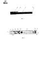
- фиг.1, на которой представлен общий вид испарителя;- figure 1, which shows a General view of the evaporator;
- фиг.2 - то же, продольный разрез (без колпачка).- figure 2 is the same, a longitudinal section (without cap).
Электронный персональный испаритель состоит из корпуса в виде полого цилиндра 1 (туба, элемент трубчатой формы), выполненного из полимерного материала, в торце корпуса 1 на заглушке 2 выполнено отверстие 3 для поступления воздуха при осуществлении вдоха со стороны мундштука, функцию которого выполняет картомайзер (парогенератор), в торце корпуса установлена заглушка (рассеиватель света 4) с пазами 5 при вдыхании включается светодиод 6, свет которого проходит через рассеиватель - сигнализатор работоспособности устройства.An electronic personal evaporator consists of a body in the form of a hollow cylinder 1 (tube, tubular-shaped element) made of polymer material, an
В корпусе расположен наполнитель 7 из нетканого (полиэфирного) полотна, пропитанный жидкостью на основе, например, пропиленгликоля и/или глицерина с ароматизатором. Воздуховод 11, например, из капрона в виде трубки, с одной стороны закреплен на заглушке 2 корпуса, имеющей, сквозное отверстие 3, а с другой установлен на заглушке 14. В зоне расположения наполнителя 7 в воздуховоде размещен фитиль 8 из кремнеземного волокна с термостойкостью до 1100-1500°С, обмотанный нитью накаливания 15, которая связана с батареей 9 электрическими проводами, пропущенными через наполнитель 7 и заглушку 14 в батарейный отсек, в котором размещен автономный источник питания 9 в виде аккумуляторной батареи напряжением 3,7-4,3 В, емкостью от 230 мАч. В корпусе со стороны батареи и рассеивателя размещен светодиод 6 и датчик давления воздуха 10 с управляющей микросхемой. Нить накаливания 15 встроена в фитиль и подсоединена к батарее через управляющую микросхему, с которой связан датчик 10 для выдачи управляющего сигнала на подключение нити накаливания 15 и светодиода 6 при изменении давления внутри корпуса по отношению к атмосферному. При разрядке батареи пользователь видит мигание или отсутствие свечения светодиода, что является сигналом к тому, что срок эксплуатации (использования) устройства окончен, или при выполнении части корпуса в области мундштука транспарантным (прозрачным) или полутранспарантным пользователь имеет возможность наблюдать состояние жидкости в наполнителе (жидкость может быть маркирована определенным цветом, при снижении окраски или тона цвета можно считать, что картомайзер исчерпал весь запас жидкости). На корпус 1 надет колпачок 13, имеющий длину, составляющую 20-50% относительно длины корпуса 1, с продольным зажимом 12. Длина зажима 12 при этом соотносима с длиной колпачка 13 и обеспечивает надежное крепление испарителя на месте размещения. Колпачок 13 и корпус 1 могут быть оснащены разъемным креплением, например резьбой или зацепом для обеспечения качества работы испарителя (правильной организации воздушного потока) с надетым колпачком.A filler 7 of a non-woven (polyester) web is placed in the housing, impregnated with a liquid based on, for example, propylene glycol and / or glycerin with a flavor. An
Claims (6)

Priority Applications (1)
| Application Number | Priority Date | Filing Date | Title |
|---|---|---|---|
| RU2013119432/12U RU132954U1 (en) | 2013-04-26 | 2013-04-26 | DISPOSABLE ELECTRONIC PERSONAL EVAPORATOR WITH PROTECTIVE CAP |
Applications Claiming Priority (1)
| Application Number | Priority Date | Filing Date | Title |
|---|---|---|---|
| RU2013119432/12U RU132954U1 (en) | 2013-04-26 | 2013-04-26 | DISPOSABLE ELECTRONIC PERSONAL EVAPORATOR WITH PROTECTIVE CAP |
Publications (1)
| Publication Number | Publication Date |
|---|---|
| RU132954U1 true RU132954U1 (en) | 2013-10-10 |
Family
ID=49303151
Family Applications (1)
| Application Number | Title | Priority Date | Filing Date |
|---|---|---|---|
| RU2013119432/12U RU132954U1 (en) | 2013-04-26 | 2013-04-26 | DISPOSABLE ELECTRONIC PERSONAL EVAPORATOR WITH PROTECTIVE CAP |
Country Status (1)
| Country | Link |
|---|---|
| RU (1) | RU132954U1 (en) |
Cited By (14)
| Publication number | Priority date | Publication date | Assignee | Title |
|---|---|---|---|---|
| RU2607767C1 (en) * | 2015-08-21 | 2017-01-10 | Общество с ограниченной ответственностью "Алгоритм" | Smoking article |
| RU2665438C1 (en) * | 2013-12-16 | 2018-08-29 | Филип Моррис Продактс С.А. | Aerosol-generating device comprising heat exchanger |
| RU2694283C1 (en) * | 2016-03-24 | 2019-07-11 | Никовенчерс Холдингз Лимитед | Electronic system for providing evaporation |
| RU2706839C2 (en) * | 2015-09-18 | 2019-11-21 | Филип Моррис Продактс С.А. | Liquid composition for electronic device for hovering |
| RU2712463C1 (en) * | 2015-06-29 | 2020-01-29 | Никовенчерс Холдингз Лимитед | Electronic systems for aerosol provision |
| RU2746743C2 (en) * | 2016-07-07 | 2021-04-20 | Филип Моррис Продактс С.А. | Electronic steaming device aromatizing unit with mechanical adjustment |
| US11033055B2 (en) | 2015-06-29 | 2021-06-15 | Nicoventures Trading Limited | Electronic aerosol provision systems, inductive heating assemblies and cartridges for use therewith, and related methods |
| US20210219611A1 (en) | 2016-03-08 | 2021-07-22 | Altria Client Services Llc | Combined cartridge for electronic vaping device |
| US11185110B2 (en) | 2015-06-29 | 2021-11-30 | Nicoventures Trading Limited | Electronic vapor provision system |
| RU2760891C1 (en) * | 2018-03-29 | 2021-12-01 | Никовенчерс Трейдинг Лимитед | Device for aerosol production from an aerosol-forming substance, an aerosol-forming substance product and a method for controlling an aerosol production device |
| RU2814991C2 (en) * | 2016-03-03 | 2024-03-11 | Филип Моррис Продактс С.А. | Electronic vaping device, cartridge for electronic vaping device and method of configuring electronic vaping device |
| US12070070B2 (en) | 2015-06-29 | 2024-08-27 | Nicoventures Trading Limited | Electronic vapor provision system |
| US12178256B2 (en) | 2016-03-11 | 2024-12-31 | Altria Client Services Llc | Multiple dispersion generator e-vaping device |
| US12178234B2 (en) | 2016-03-03 | 2024-12-31 | Altria Client Services Llc | Methods to add menthol, botanic materials, and/or non-botanic materials to a cartridge, and/or an electronic vaping device including the cartridge |
-
2013
- 2013-04-26 RU RU2013119432/12U patent/RU132954U1/en not_active IP Right Cessation
Cited By (23)
| Publication number | Priority date | Publication date | Assignee | Title |
|---|---|---|---|---|
| US11384743B2 (en) | 2013-12-16 | 2022-07-12 | Philip Morris Products S.A. | Aerosol-generating device comprising a heat exchanger |
| RU2665438C1 (en) * | 2013-12-16 | 2018-08-29 | Филип Моррис Продактс С.А. | Aerosol-generating device comprising heat exchanger |
| US11185110B2 (en) | 2015-06-29 | 2021-11-30 | Nicoventures Trading Limited | Electronic vapor provision system |
| US11896055B2 (en) | 2015-06-29 | 2024-02-13 | Nicoventures Trading Limited | Electronic aerosol provision systems |
| RU2712463C1 (en) * | 2015-06-29 | 2020-01-29 | Никовенчерс Холдингз Лимитед | Electronic systems for aerosol provision |
| US10881141B2 (en) | 2015-06-29 | 2021-01-05 | Nicoventures Holdings Limited | Electronic aerosol provision systems |
| US12232533B2 (en) | 2015-06-29 | 2025-02-25 | Nicoventures Trading Limited | Inductive heating assemblies for generating an aerosol |
| US11033055B2 (en) | 2015-06-29 | 2021-06-15 | Nicoventures Trading Limited | Electronic aerosol provision systems, inductive heating assemblies and cartridges for use therewith, and related methods |
| US12070070B2 (en) | 2015-06-29 | 2024-08-27 | Nicoventures Trading Limited | Electronic vapor provision system |
| US11882877B2 (en) | 2015-06-29 | 2024-01-30 | Nicoventures Trading Limited | Electronic vapor provision system |
| RU2607767C1 (en) * | 2015-08-21 | 2017-01-10 | Общество с ограниченной ответственностью "Алгоритм" | Smoking article |
| RU2706839C2 (en) * | 2015-09-18 | 2019-11-21 | Филип Моррис Продактс С.А. | Liquid composition for electronic device for hovering |
| US12178234B2 (en) | 2016-03-03 | 2024-12-31 | Altria Client Services Llc | Methods to add menthol, botanic materials, and/or non-botanic materials to a cartridge, and/or an electronic vaping device including the cartridge |
| RU2814991C2 (en) * | 2016-03-03 | 2024-03-11 | Филип Моррис Продактс С.А. | Electronic vaping device, cartridge for electronic vaping device and method of configuring electronic vaping device |
| US20210219611A1 (en) | 2016-03-08 | 2021-07-22 | Altria Client Services Llc | Combined cartridge for electronic vaping device |
| US12171262B2 (en) | 2016-03-08 | 2024-12-24 | Altria Client Services Llc | Combined cartridge for electronic vaping device |
| US12245632B2 (en) | 2016-03-08 | 2025-03-11 | Altria Client Services Llc | Combined cartridge for electronic vaping device |
| US12178256B2 (en) | 2016-03-11 | 2024-12-31 | Altria Client Services Llc | Multiple dispersion generator e-vaping device |
| RU2694283C1 (en) * | 2016-03-24 | 2019-07-11 | Никовенчерс Холдингз Лимитед | Electronic system for providing evaporation |
| US11123501B2 (en) | 2016-03-24 | 2021-09-21 | Nicoventures Holdings Limited | Electronic vapor provision system |
| RU2746743C2 (en) * | 2016-07-07 | 2021-04-20 | Филип Моррис Продактс С.А. | Electronic steaming device aromatizing unit with mechanical adjustment |
| US11998057B2 (en) | 2018-03-29 | 2024-06-04 | Nicoventures Trading Limited | Apparatus for generation aerosol from an aerosolizable medium, an article of aerosolizable medium and a method of operating an aerosol generating apparatus |
| RU2760891C1 (en) * | 2018-03-29 | 2021-12-01 | Никовенчерс Трейдинг Лимитед | Device for aerosol production from an aerosol-forming substance, an aerosol-forming substance product and a method for controlling an aerosol production device |
Similar Documents
| Publication | Publication Date | Title |
|---|---|---|
| RU132954U1 (en) | DISPOSABLE ELECTRONIC PERSONAL EVAPORATOR WITH PROTECTIVE CAP | |
| RU122000U1 (en) | VARIABLE TASTE ELECTRONIC CIGARETTE | |
| RU116018U1 (en) | DISPOSABLE ELECTRONIC CIGARETTE | |
| US10561170B2 (en) | Electronic pipe | |
| RU110608U1 (en) | ELECTRONIC CIGARETTE | |
| RU124120U1 (en) | RECHARGEABLE (DISPOSABLE) ELECTRONIC CIGARETTE | |
| RU115629U1 (en) | ELECTRONIC CIGARETTE | |
| ES2933691T3 (en) | Smoking articles and their use to produce inhalation materials | |
| RU103281U1 (en) | ELECTRONIC CIGARETTE | |
| RU138386U1 (en) | DISPOSABLE ELECTRONIC PERSONAL EVAPORATOR (OPTIONS) | |
| RU121706U1 (en) | DISPOSABLE ELECTRONIC CIGARETTE | |
| JP2023162427A (en) | Quasi-resonant flyback converter for induction-based aerosol delivery device | |
| US20130319431A1 (en) | Electronic cigarette | |
| US20120318882A1 (en) | Vapor delivery devices | |
| BR112019020460A2 (en) | aerosol delivery device with improved atomizer | |
| US20190075847A1 (en) | Electronic cigarette | |
| JP2020517250A (en) | Refillable aerosol delivery device and related methods | |
| BR112021003590A2 (en) | aerosol delivery device with integrated thermal conductor | |
| CN104540406A (en) | Reservoir and heater system for controllable delivery of multiple aerosolizable materials in an electronic smoking article | |
| RU122254U1 (en) | DISPOSABLE ELECTRONIC CIGARETTE | |
| US20200221763A1 (en) | Electronic cigarette | |
| UA78167U (en) | Disposable electronic cigarette | |
| RU150594U1 (en) | DISPOSABLE ELECTRONIC PERSONAL EVAPORATOR WITH PROTECTIVE CAP | |
| RU129368U1 (en) | PORTABLE ELECTRONIC INHALER | |
| RU110607U1 (en) | ELECTRONIC CIGARETTE |
Legal Events
| Date | Code | Title | Description |
|---|---|---|---|
| PC11 | Official registration of the transfer of exclusive right |
Effective date: 20151119 |
|
| QB1K | Licence on use of utility model |
Free format text: LICENCE Effective date: 20170627 |
|
| MM9K | Utility model has become invalid (non-payment of fees) |
Effective date: 20200427 |