KR20240086995A - Refrigeratgor - Google Patents
Refrigeratgor Download PDFInfo
- Publication number
- KR20240086995A KR20240086995A KR1020220172257A KR20220172257A KR20240086995A KR 20240086995 A KR20240086995 A KR 20240086995A KR 1020220172257 A KR1020220172257 A KR 1020220172257A KR 20220172257 A KR20220172257 A KR 20220172257A KR 20240086995 A KR20240086995 A KR 20240086995A
- Authority
- KR
- South Korea
- Prior art keywords
- operating member
- door
- link
- supporter
- handle
- Prior art date
- Legal status (The legal status is an assumption and is not a legal conclusion. Google has not performed a legal analysis and makes no representation as to the accuracy of the status listed.)
- Pending
Links
Images


Classifications
-
- F—MECHANICAL ENGINEERING; LIGHTING; HEATING; WEAPONS; BLASTING
- F25—REFRIGERATION OR COOLING; COMBINED HEATING AND REFRIGERATION SYSTEMS; HEAT PUMP SYSTEMS; MANUFACTURE OR STORAGE OF ICE; LIQUEFACTION SOLIDIFICATION OF GASES
- F25D—REFRIGERATORS; COLD ROOMS; ICE-BOXES; COOLING OR FREEZING APPARATUS NOT OTHERWISE PROVIDED FOR
- F25D23/00—General constructional features
- F25D23/02—Doors; Covers
- F25D23/028—Details
-
- E—FIXED CONSTRUCTIONS
- E05—LOCKS; KEYS; WINDOW OR DOOR FITTINGS; SAFES
- E05B—LOCKS; ACCESSORIES THEREFOR; HANDCUFFS
- E05B5/00—Handles completely let into the surface of the wing
- E05B5/006—Handles completely let into the surface of the wing essentially defining a completely closed surface together with the wing
-
- E—FIXED CONSTRUCTIONS
- E05—LOCKS; KEYS; WINDOW OR DOOR FITTINGS; SAFES
- E05F—DEVICES FOR MOVING WINGS INTO OPEN OR CLOSED POSITION; CHECKS FOR WINGS; WING FITTINGS NOT OTHERWISE PROVIDED FOR, CONCERNED WITH THE FUNCTIONING OF THE WING
- E05F11/00—Man-operated mechanisms for operating wings, including those which also operate the fastening
- E05F11/54—Man-operated mechanisms for operating wings, including those which also operate the fastening for doors
-
- F—MECHANICAL ENGINEERING; LIGHTING; HEATING; WEAPONS; BLASTING
- F25—REFRIGERATION OR COOLING; COMBINED HEATING AND REFRIGERATION SYSTEMS; HEAT PUMP SYSTEMS; MANUFACTURE OR STORAGE OF ICE; LIQUEFACTION SOLIDIFICATION OF GASES
- F25D—REFRIGERATORS; COLD ROOMS; ICE-BOXES; COOLING OR FREEZING APPARATUS NOT OTHERWISE PROVIDED FOR
- F25D11/00—Self-contained movable devices, e.g. domestic refrigerators
- F25D11/02—Self-contained movable devices, e.g. domestic refrigerators with cooling compartments at different temperatures
-
- F—MECHANICAL ENGINEERING; LIGHTING; HEATING; WEAPONS; BLASTING
- F25—REFRIGERATION OR COOLING; COMBINED HEATING AND REFRIGERATION SYSTEMS; HEAT PUMP SYSTEMS; MANUFACTURE OR STORAGE OF ICE; LIQUEFACTION SOLIDIFICATION OF GASES
- F25D—REFRIGERATORS; COLD ROOMS; ICE-BOXES; COOLING OR FREEZING APPARATUS NOT OTHERWISE PROVIDED FOR
- F25D23/00—General constructional features
- F25D23/02—Doors; Covers
- F25D23/021—Sliding doors
-
- F—MECHANICAL ENGINEERING; LIGHTING; HEATING; WEAPONS; BLASTING
- F25—REFRIGERATION OR COOLING; COMBINED HEATING AND REFRIGERATION SYSTEMS; HEAT PUMP SYSTEMS; MANUFACTURE OR STORAGE OF ICE; LIQUEFACTION SOLIDIFICATION OF GASES
- F25D—REFRIGERATORS; COLD ROOMS; ICE-BOXES; COOLING OR FREEZING APPARATUS NOT OTHERWISE PROVIDED FOR
- F25D25/00—Charging, supporting, and discharging the articles to be cooled
- F25D25/02—Charging, supporting, and discharging the articles to be cooled by shelves
- F25D25/024—Slidable shelves
- F25D25/025—Drawers
-
- E—FIXED CONSTRUCTIONS
- E05—LOCKS; KEYS; WINDOW OR DOOR FITTINGS; SAFES
- E05Y—INDEXING SCHEME ASSOCIATED WITH SUBCLASSES E05D AND E05F, RELATING TO CONSTRUCTION ELEMENTS, ELECTRIC CONTROL, POWER SUPPLY, POWER SIGNAL OR TRANSMISSION, USER INTERFACES, MOUNTING OR COUPLING, DETAILS, ACCESSORIES, AUXILIARY OPERATIONS NOT OTHERWISE PROVIDED FOR, APPLICATION THEREOF
- E05Y2201/00—Constructional elements; Accessories therefor
- E05Y2201/60—Suspension or transmission members; Accessories therefor
- E05Y2201/622—Suspension or transmission members elements
- E05Y2201/676—Transmission of human force
- E05Y2201/68—Handles, cranks
-
- E—FIXED CONSTRUCTIONS
- E05—LOCKS; KEYS; WINDOW OR DOOR FITTINGS; SAFES
- E05Y—INDEXING SCHEME ASSOCIATED WITH SUBCLASSES E05D AND E05F, RELATING TO CONSTRUCTION ELEMENTS, ELECTRIC CONTROL, POWER SUPPLY, POWER SIGNAL OR TRANSMISSION, USER INTERFACES, MOUNTING OR COUPLING, DETAILS, ACCESSORIES, AUXILIARY OPERATIONS NOT OTHERWISE PROVIDED FOR, APPLICATION THEREOF
- E05Y2400/00—Electronic control; Electrical power; Power supply; Power or signal transmission; User interfaces
- E05Y2400/10—Electronic control
- E05Y2400/30—Electronic control of motors
- E05Y2400/3013—Electronic control of motors during manual wing operation
-
- E—FIXED CONSTRUCTIONS
- E05—LOCKS; KEYS; WINDOW OR DOOR FITTINGS; SAFES
- E05Y—INDEXING SCHEME ASSOCIATED WITH SUBCLASSES E05D AND E05F, RELATING TO CONSTRUCTION ELEMENTS, ELECTRIC CONTROL, POWER SUPPLY, POWER SIGNAL OR TRANSMISSION, USER INTERFACES, MOUNTING OR COUPLING, DETAILS, ACCESSORIES, AUXILIARY OPERATIONS NOT OTHERWISE PROVIDED FOR, APPLICATION THEREOF
- E05Y2600/00—Mounting or coupling arrangements for elements provided for in this subclass
- E05Y2600/40—Mounting location; Visibility of the elements
- E05Y2600/41—Concealed
-
- E—FIXED CONSTRUCTIONS
- E05—LOCKS; KEYS; WINDOW OR DOOR FITTINGS; SAFES
- E05Y—INDEXING SCHEME ASSOCIATED WITH SUBCLASSES E05D AND E05F, RELATING TO CONSTRUCTION ELEMENTS, ELECTRIC CONTROL, POWER SUPPLY, POWER SIGNAL OR TRANSMISSION, USER INTERFACES, MOUNTING OR COUPLING, DETAILS, ACCESSORIES, AUXILIARY OPERATIONS NOT OTHERWISE PROVIDED FOR, APPLICATION THEREOF
- E05Y2900/00—Application of doors, windows, wings or fittings thereof
- E05Y2900/30—Application of doors, windows, wings or fittings thereof for domestic appliances
- E05Y2900/31—Application of doors, windows, wings or fittings thereof for domestic appliances for refrigerators
-
- F—MECHANICAL ENGINEERING; LIGHTING; HEATING; WEAPONS; BLASTING
- F25—REFRIGERATION OR COOLING; COMBINED HEATING AND REFRIGERATION SYSTEMS; HEAT PUMP SYSTEMS; MANUFACTURE OR STORAGE OF ICE; LIQUEFACTION SOLIDIFICATION OF GASES
- F25D—REFRIGERATORS; COLD ROOMS; ICE-BOXES; COOLING OR FREEZING APPARATUS NOT OTHERWISE PROVIDED FOR
- F25D2323/00—General constructional features not provided for in other groups of this subclass
- F25D2323/02—Details of doors or covers not otherwise covered
Landscapes
- Engineering & Computer Science (AREA)
- Chemical & Material Sciences (AREA)
- Combustion & Propulsion (AREA)
- Physics & Mathematics (AREA)
- Mechanical Engineering (AREA)
- Thermal Sciences (AREA)
- General Engineering & Computer Science (AREA)
- Refrigerator Housings (AREA)
Abstract
Description
본 발명은 냉장고에 관한 것이다.The present invention relates to refrigerators.
일반적으로 냉장고는 도어에 의해 차폐되는 내부의 저장공간에 음식물을 저온 저장할 수 있도록 하는 가전 기기이다. 이를 위해 냉장고는 냉동사이클을 순환하는 냉매와의 열교환을 통해 발생하는 냉기를 이용하여 저장공간의 내부를 냉각함으로써 저장된 음식물들을 최적상태로 보관할 수 있도록 구성된다.In general, a refrigerator is a home appliance that allows food to be stored at low temperatures in an internal storage space shielded by a door. To this end, refrigerators are designed to keep stored food in optimal condition by cooling the inside of the storage space using cold air generated through heat exchange with the refrigerant circulating in the refrigeration cycle.
최근의 냉장고는 식생활의 변화 및 제품의 고급화의 추세에 따라 점차 대형화 다기능화되고 있는 추세이며, 사용자의 편의 및 내부 공간을 효율적으로 사용할 수 있도록 하는 다양한 구조 및 편의장치를 구비한 냉장고가 출시되고 있다.Recently, refrigerators are gradually becoming larger and more multi-functional in accordance with changes in eating habits and the trend of higher quality products, and refrigerators equipped with various structures and convenience devices are being released to ensure user convenience and efficient use of internal space. .
냉장고의 저장 공간은 도어에 의해 개폐될 수 있다. 그리고, 상기 저장 공간의 배치형태와 상기 저장공간을 개폐하는 도어의 구조에 따라서 다양한 형태의 냉장고로 분류될 수 있다.The storage space of the refrigerator can be opened and closed by a door. Refrigerators can be classified into various types depending on the arrangement of the storage space and the structure of the door that opens and closes the storage space.
통상적으로, 냉장고의 도어는 회전에 의해 개폐되거나, 슬라이딩 인출입에 의해 개폐되는 구조를 가질 수 있다. 그리고, 도어의 개방 조작을 위해서 손잡이가 돌출되거나 함몰되는 구조를 가질 수 있다. Typically, the door of a refrigerator may have a structure that opens and closes by rotation or by sliding in and out. Additionally, the handle may have a structure in which the handle protrudes or is recessed in order to open the door.
그리고, 도어의 크기가 크고 무거운 경우, 고내가 저온이 되어 음압이 발생된 경우, 도어 가스켓의 자력에 의한 경우 등 도어의 개방시 많은 힘이 필요할 수 있으며, 이로 인해 사용자의 불편을 초래할 수 있다. In addition, when the door is large and heavy, when the temperature inside the cabinet is low and negative pressure is generated, or when the door gasket is magnetic, a lot of force may be required to open the door, which may cause inconvenience to the user.
이와 같은 문제를 해결하기 위해서 사용자의 도어 개방을 용이하게 하는 장치가 개발되고 있다.To solve this problem, devices that facilitate the user's opening of the door are being developed.
본 발명의 실시 예는 함몰된 도어의 손잡이 내부에 도어 개방 장치가 배치되어 외관을 개선하는 냉장고를 제공하는 것을 목적으로 한다.The purpose of an embodiment of the present invention is to provide a refrigerator whose appearance is improved by placing a door opening device inside the handle of a recessed door.
본 발명의 실시 예는 도어 개방을 위한 함몰된 손잡이의 조작시 도어의 개방이 용이하게 이루어지는 냉장고를 제공하는 것을 목적으로 한다. The purpose of an embodiment of the present invention is to provide a refrigerator in which the door can be easily opened when the recessed handle for opening the door is manipulated.
본 발명은 도어 개방장치의 조작부재의 외관을 유지하면서 강도가 보강될 수 있는 냉장고를 제공하는 것을 목적으로 한다.The purpose of the present invention is to provide a refrigerator whose strength can be strengthened while maintaining the appearance of the operating member of the door opening device.
본 발명의 실시 예에 따른 냉장고는, 저장 공간을 형성하는 캐비닛; 상기 저장 공간을 개폐하며, 내부에 단열재가 채워진 도어; 상기 도어의 둘레면 적어도 일부를 형성하며, 상기 도어 내측으로 함몰된 손잡이가 형성된 캡데코; 및 상기 도어에 구비되며, 상기 도어의 개방을 위해 사용자가 조작하는 도어 개방장치를 포함하며, 상기 도어 개방장치는, 상기 캡데코에 장착되며, 상기 도어 내부에서 상기 단열재와 독립된 공간을 형성하는 케이스와; 상기 케이스 내부에 동작 가능하게 장착되며, 사용자가 조작하는 조작부재를 포함하며, 상기 캡데코에는 상기 케이스 및 상기 손잡이와 연통되는 손잡이 개구가 형성되고, 상기 조작부재는 상기 손잡이 개구를 통과하여 상기 손잡이 내부로 연장될 수 있다. A refrigerator according to an embodiment of the present invention includes a cabinet forming a storage space; a door that opens and closes the storage space and whose interior is filled with insulation; a cap deco that forms at least a portion of the circumferential surface of the door and has a handle recessed inside the door; and a door opening device provided on the door and operated by a user to open the door, wherein the door opening device is mounted on the cap deco and forms a space inside the door independent of the insulation material. and; It is operably mounted inside the case and includes an operating member operated by a user, wherein the cap deco has a handle opening communicating with the case and the handle, and the operating member passes through the handle opening to form the handle. It can be extended internally.
상기 조작부재는 상기 도어의 전면을 형성하는 도어 플레이트에 의해 전방에서 차폐될 수 있다. The operating member may be shielded from the front by a door plate forming the front of the door.
상기 조작부재는 상기 손잡이의 중앙을 기준으로 전방에 위치될 수 있다. The operating member may be located in front of the center of the handle.
상기 조작부재는 상기 도어의 전면과 가까워지는 방향으로 조작되도록 장착될 수 있다. The operating member may be mounted to be operated in a direction closer to the front of the door.
상기 손잡이 개구는 상기 도어의 전면 및 하면을 향하여 개구될 수 있다.The handle opening may be open toward the front and bottom surfaces of the door.
상기 조작부재는 상기 손잡이 개구를 차폐하도록 대응하는 형상으로 형성될 수 있다. The operating member may be formed in a corresponding shape to shield the handle opening.
상기 조작부재는 상기 케이스에 회전 가능하게 장착되며, 상기 조작부재의 회전시 상기 조작부재는 상기 손잡이 개구의 내부로 삽입될 수 있다.The operating member is rotatably mounted on the case, and when the operating member rotates, the operating member may be inserted into the handle opening.
상기 도어 개방장치는, 상기 도어의 후방으로 선택적으로 돌출되어 상기 캐비닛 전면을 밀어주는 푸시부재; 상기 푸시부재를 탄성 지지하는 탄성부재; 및 상기 조작부재 및 푸시부재와 접하여, 상기 조작부재의 동작시 상기 푸시부재를 동작시키는 링크;를 포함하며, 상기 조작부재, 탄성부재, 링크 및 푸시부재는 상기 케이스의 내부에 장착될 수 있다.The door opening device includes a push member that selectively protrudes toward the rear of the door and pushes the front of the cabinet; an elastic member elastically supporting the push member; and a link that is in contact with the operating member and the push member, and operates the push member when the operating member operates. The operating member, the elastic member, the link, and the push member may be mounted inside the case.
상기 조작부재 및 링크는 상기 케이스에 회전 가능하게 장착되며, 상기 조작부재 회전축과, 링크 회전축은 서로 나란히 배치될 수 있다. The operating member and the link are rotatably mounted on the case, and the operating member rotation axis and the link rotation axis may be arranged parallel to each other.
상기 조작부재는 후면이 상기 손잡이의 내측으로 노출되고, 상기 조작부재의 전면에는 상기 조작부재보다 더 강도가 높은 소재로 형성되어 상기 조작부재의 강도를 보강하는 서포터가 결합될 수 있다.The back of the operating member is exposed to the inside of the handle, and a supporter formed of a material stronger than the operating member and reinforcing the strength of the operating member may be coupled to the front of the operating member.
상기 서포터는, 상기 조작부재의 전면을 지지하는 서포터 바디; 상기 서포터 바디에서 돌출되어 상기 케이스에 축결합되며, 상기 조작부재의 회전축이 되는 서포터 회전축을 포함할 수 있다.The supporter includes a supporter body supporting the front of the operating member; It protrudes from the supporter body and is axially coupled to the case, and may include a supporter rotation axis that becomes the rotation axis of the operating member.
상기 서포터는 상기 서포터 회전축 보다 전방으로 더 연장되어 상기 링크와 접하며, 상기 조작부재의 회전시 상기 링크를 회전시키는 서포터 연장부를 포함할 수 있다.The supporter extends further forward than the supporter rotation axis and is in contact with the link, and may include a supporter extension part that rotates the link when the operating member rotates.
상기 서포터 바디에는 다수의 보강 리브가 형성되며, 상기 보강 리브는 서로 교차되도록 형성될 수 있다.A plurality of reinforcing ribs are formed on the supporter body, and the reinforcing ribs may be formed to cross each other.
상기 서포터는 금속 막대 형상으로 형성되며, 상기 조작부재의 일단에서 타단까지 상기 조작부재의 길이 방향으로 연장될 수 있다.The supporter is formed in the shape of a metal rod and may extend in the longitudinal direction of the operating member from one end to the other end of the operating member.
상기 서포터는 상기 조작부재의 전면과 대응하는 금속 판 형상으로 형성되며, 상기 조작부재의 전면을 지지할 수 있다.The supporter is formed in the shape of a metal plate corresponding to the front of the operating member, and can support the front of the operating member.
상기 도어 개방장치는, 상기 도어의 후방으로 선택적으로 돌출되어 상기 캐비닛과 접하는 푸시부재; 상기 푸시부재를 탄성 지지하는 탄성부재; 상기 케이스에 축결합되며, 회전에 의해 상기 푸시부재를 전후 이동시키는 제 1 링크; 및 상기 조작부재와 이종 소재로 형성되어 상기 조작부재에 결합되며, 상기 조작부재의 회전축이 되는 제 2 링크;를 포함하며, 상기 제 2 링크는 상기 제 1 링크와 접하여 상기 조작부재의 회전력을 상기 제 1 링크로 전달할 수 있다.The door opening device includes a push member that selectively protrudes toward the rear of the door and contacts the cabinet; an elastic member elastically supporting the push member; a first link that is axially coupled to the case and moves the push member back and forth by rotation; And a second link formed of a different material from the operating member, coupled to the operating member, and serving as a rotation axis of the operating member, wherein the second link is in contact with the first link and transmits the rotational force of the operating member. It can be forwarded to the first link.
상기 조작부재에는 금속소재로 형성되어 상기 조작부재의 강도를 보강하는 서포터가 결합되며, 상기 서포터는, 상기 조작부재의 전면을 지지하는 제 1 지지부와, 상기 제 1 지지부의 하단에서 절곡되며, 상기 제 2 링크의 하면을 지지하는 제 2 지지부를 포함할 수 있다.A supporter made of a metal material and reinforcing the strength of the operating member is coupled to the operating member. The supporter includes a first support portion supporting the front surface of the operating member and is bent at a lower end of the first support portion. It may include a second support portion supporting the lower surface of the second link.
상기 서포터에는 함몰된 포밍부가 형성되며, 상기 포밍부는 상기 제 1 지지부와 제 2 지지부의 연장 방향으로 연장될 수 있다.A recessed forming part is formed in the supporter, and the forming part may extend in an extension direction of the first support part and the second support part.
상기 캐비닛과 도어를 연결하여, 상기 도어가 인출입되도록 하는 레일을 포함하며, 상기 도어는 서랍식 도어일 수 있다.It includes a rail that connects the cabinet and the door to allow the door to be pulled in and out, and the door may be a drawer-type door.
상기 캐비닛과 도어를 연결하여, 상기 도어가 회전되도록 하는 힌지 장치를 포함하며, 상기 도어는 회전식 도어일 수 있다.It includes a hinge device that connects the cabinet and the door to allow the door to rotate, and the door may be a rotary door.
제안되는 실시 예에 따른 냉장고에서는 다음과 같은 효과를 기대할 수 있다.The following effects can be expected from the refrigerator according to the proposed embodiment.
본 발명의 실시 예에 의한 냉장고는 도어 개방장치가 구비되어 도어의 개방이 용이하면서도 상기 도어 개방장치가 노출되지 않도록 하여 외관이 개선되는 효과를 기대할 수 있다. The refrigerator according to an embodiment of the present invention is equipped with a door opening device, so that the door can be easily opened, but the appearance can be expected to be improved by preventing the door opening device from being exposed.
특히, 사용자가 조작하는 조작부재가 함몰된 손잡이의 내부에 배치되어 전방에서 볼 때 조작부재를 포함하는 도어 개방장치가 노출되지 않아 외관이 한층더 개선되는 효과가 있다. In particular, since the operating member operated by the user is disposed inside the recessed handle, the door opening device including the operating member is not exposed when viewed from the front, thereby further improving the appearance.
또한, 상기 조작부재는 상기 손잡이의 중앙을 기준으로 전방으로 배치되어 사용자가 상기 도어의 개방을 위해 손잡이를 잡게 될 때 자연스럽게 조작되어 사용 편의성이 향상될 수 있다. In addition, the operating member is disposed forward relative to the center of the handle, so that it can be naturally operated when the user holds the handle to open the door, thereby improving convenience of use.
그리고, 상기 조작부재는 상기 도어의 전면을 향하여 회전되면서 동작되어 사용자가 상기 손잡이를 잡고 당기는 한번의 동작만으로 도어의 개방이 용이하게 이루어질 수 있어 사용 편의성이 한층 더 향상될 수 있다. In addition, the operating member operates while rotating toward the front of the door, so that the user can easily open the door with just one action of holding and pulling the handle, thereby further improving convenience of use.
그리고, 사용자의 손과 닿는 상기 조작부재는 질감이 우수한 소재로 형성될 수 있으며, 상기 손잡이의 내면과 조화를 이룰 수 있는 표면성을 가지는 소재로 형성될 수 있어 외관과 사용성을 개선할 수 있는 이점이 있다. In addition, the operating member that touches the user's hand can be made of a material with excellent texture and can be made of a material that has a surface that harmonizes with the inner surface of the handle, which has the advantage of improving appearance and usability. There is.
또한, 상기 조작부재에는 강도를 보강하는 서포터가 구비되어 외관과 사용성이 개선된 조작부재를 사용하면서도 파손 또는 변형되지 않고 내구성이 보장될 수 있는 이점이 있다. In addition, the operating member is provided with a supporter that reinforces its strength, so there is an advantage that durability can be guaranteed without being damaged or deformed while using an operating member with improved appearance and usability.
도 1은 본 발명의 제 1 실시 예에 의한 냉장고의 사시도이다.
도 2는 상기 냉장고의 도어가 개방된 사시도이다.
도 3은 상기 도어의 상부를 확대한 도면이다.
도 4는 상기 도어의 분해 사시도이다.
도 5는 상기 도어의 캡 데코와 도어 개방장치의 결합 구조를 보인 분해 사시도이다.
도 6은 상기 캡데코의 하면을 보인 사시도이다.
도 7은 상기 도어 개방장치가 분해된 모습을 전방에서 본 분해 사시도이다.
도 8은 상기 도어 개방장치가 분해된 모습을 후방에서 본 분해 사시도이다.
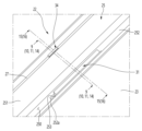
도 9는 도 3의 9-9 절개 사시도이다.
도 10은 상기 도어 개방장치의 조작 전 상태를 나타낸 단면도이다.
도 11은 상기 도어 개방장치의 조작 상태를 나타낸 단면도이다.
도 12는 본 발명의 제 2 실시 예에 의한 도어 개방장치가 분해된 모습을 전방에서 본 분해 사시도이다.
도 13은 상기 도어 개방장치가 분해된 모습을 후방에서 본 분해 사시도이다.
도 14는 도 3의 14-14 절개 사시도이다.
도 15는 상기 도어 개방장치의 조작 전 상태를 나타낸 단면도이다.
도 16은 상기 도어 개방장치의 조작 상태를 나타낸 단면도이다.
도 17은 본 발명의 제 3 실시 예에 의한 도어 개방장치의 조작부재를 전방에서 본 사시도이다.
도 18은 본 발명의 제 4 실시 예에 의한 도어 개방장치의 조작부재를 후방에서 본 사시도이다.
도 19는 상기 조작부재를 전방에서 본 사시도이다.
도 20은 도 19의 20-20 절개 사시도이다. 1 is a perspective view of a refrigerator according to a first embodiment of the present invention.
Figure 2 is a perspective view of the refrigerator with the door open.
Figure 3 is an enlarged view of the upper part of the door.
Figure 4 is an exploded perspective view of the door.
Figure 5 is an exploded perspective view showing the combined structure of the door cap decoration and the door opening device.
Figure 6 is a perspective view showing the bottom of the cap deco.
Figure 7 is an exploded perspective view of the door opening device disassembled as seen from the front.
Figure 8 is an exploded perspective view of the door opening device disassembled as seen from the rear.
Figure 9 is a perspective view taken along line 9-9 of Figure 3.
Figure 10 is a cross-sectional view showing the state before operation of the door opening device.
Figure 11 is a cross-sectional view showing the operating state of the door opening device.
Figure 12 is an exploded perspective view of the door opening device according to the second embodiment of the present invention as seen from the front.
Figure 13 is an exploded perspective view of the door opening device disassembled as seen from the rear.
Figure 14 is a perspective view taken along line 14-14 of Figure 3.
Figure 15 is a cross-sectional view showing the state before operation of the door opening device.
Figure 16 is a cross-sectional view showing the operating state of the door opening device.
Figure 17 is a perspective view of the operating member of the door opening device according to the third embodiment of the present invention as seen from the front.
Figure 18 is a perspective view of the operating member of the door opening device according to the fourth embodiment of the present invention as seen from the rear.
Figure 19 is a perspective view of the operating member viewed from the front.
Figure 20 is a perspective view taken along the line 20-20 of Figure 19.
이하에서는 본 발명의 구체적인 실시 예를 도면과 함께 상세히 설명하도록 한다. 그러나 본 발명은 본 발명의 사상이 제시되는 실시 예에 제한된다고 할 수 없으며, 또 다른 구성요소의 추가, 변경, 삭제 등에 의해서 퇴보적인 다른 발명이나 본 발명의 사상범위 내에 포함되는 다른 실시 예를 용이하게 제안할 수 있다.Hereinafter, specific embodiments of the present invention will be described in detail along with the drawings. However, the present invention cannot be said to be limited to the embodiments in which the idea of the present invention is presented, and other inventions that are regressive or other embodiments included within the scope of the present invention can be easily developed by adding, changing, or deleting other components. can be suggested.
설명에 앞서 방향을 정의한다. 본 발명의 실시 예는 도 1 에서 보이는 도어의 전면이 향하는 방향을 전방, 도어의 전면을 기준으로 캐비닛을 향하는 방향을 후방 그리고, 냉장고가 설치되는 바닥면을 향하는 방향을 하방, 그리고 바닥면에서 멀어지는 방향을 상방으로 정의할 수 있다.Before explaining, define the direction. In an embodiment of the present invention, the direction in which the front of the door shown in Figure 1 faces is forward, the direction toward the cabinet based on the front of the door is backward, the direction toward the floor where the refrigerator is installed is downward, and the direction toward the floor where the refrigerator is installed is downward. The direction can be defined as upward.
도 1은 본 발명의 제 1 실시 예에 의한 냉장고의 사시도이다. 그리고, 도 2는 상기 냉장고의 도어가 개방된 사시도이다. 그리고, 도 3은 상기 도어의 상부를 확대한 도면이다. 1 is a perspective view of a refrigerator according to a first embodiment of the present invention. And, Figure 2 is a perspective view with the door of the refrigerator open. And, Figure 3 is an enlarged view of the upper part of the door.
도시된 것과 같이, 본 발명의 제 1 실시 예에 의한 냉장고(1)는 저장공간을 형성하는 캐비닛(10)과, 상기 저장공간을 개폐하는 도어(20)를 포함할 수 있다.As shown, the
상기 캐비닛(10)의 저장 공간은 베리어(11)에 의해 상하로 구획될 수 있으며, 상부에는 냉장실(12)이 형성될 수 있고 하부에는 냉동실(13)이 형성될 수 있다. 그리고, 상기 도어(20)는 상기 냉장실(12)을 개폐하는 냉장실 도어(21)와, 상기 냉동실(13)을 개폐하는 냉동실 도어(22)로 구성될 수 있다. The storage space of the
상기 냉장실 도어(21)는 좌우 양측에 한쌍의 도어가 회전 가능하도록 힌지 장치(201)에 의해 상기 캐비닛(10)에 장착될 수 있다. 그리고, 상기 냉장실 도어(21)는 회전에 의해 상기 냉장실(12)을 개폐할 수 있다. 따라서, 상기 냉장실 도어(21)는 회전식 도어라 부를 수 있다. 그리고, 상기 냉장실 도어(21)의 하면에는 사용자가 손을 넣어 상기 도어(20)를 회전 조작할 수 있는 손잡이가 구비될 수 있다. The refrigerating
상기 냉동실 도어(22)는 상기 캐비닛(10)에 슬라이딩 인출입 가능하도록 장착될 수 있다. 그리고, 상기 냉동실 도어(22)의 인출입에 의해 상기 냉동실(13)을 개폐할 수 있다. 그리고, 상기 냉동실 도어(22)는 도어 후면에 바스켓(282)을 포함하며 서랍과 같은 형태로 구성될 수 있다. 따라서, 상기 냉동실 도어(22)는 서랍식 도어(20)라 부를 수 있다. 그리고, 상기 냉동실 도어(22)의 상면에는 사용자가 손을 넣어 상기 냉동실 도어(22)를 인출입 조작할 수 있는 손잡이(250)가 구비될 수 있다. The
본 발명의 실시 예에서는 냉동실(13)이 하방에 구비되는 바텀 프리즈 타입의 냉장고를 예를 들어 설명하고 있으나, 본 발명은 상기 손잡이(250)가 함몰된 형태를 가지는 모든 타입의 도어에 적용될 수 있을 것이다. 그리고, 상기 손잡이(250)에 도어 개방장치(30)가 배치되어 상기 냉동실 도어(22)의 개방 조작을 보다 용이하게 할 수 있다. 본 실시 예에서는 상기 도어 개방장치(30)가 냉동실 도어(22) 또는 서랍식 도어에 적용된 것을 예를 들어 설명하기로 한다. 물론, 상기 도어 개방장치(30)는 냉장실 도어(21) 또는 회전식 도어에 구비될 수도 있다. In the embodiment of the present invention, a bottom freeze type refrigerator in which the
상기 냉동실 도어(22)의 상면에는 상기 손잡이(250)가 함몰 형성될 수 있다. 그리고, 상기 손잡이(250)의 함몰된 내부에는 사용자가 조작할 수 있는 조작부재(31)가 배치될 수 있다. 상기 조작부재(31)는 상기 손잡이(250)의 함몰된 내면에 배치되며, 상기 손잡이(250)의 중앙을 기준으로 보다 전방에 배치될 수 있다. 따라서 사용자가 상기 냉동실 도어(22) 개방을 위해 상기 손잡이(250)를 쥐게 되면 자연스럽게 상기 조작부재(31)가 조작되도록 구성될 수 있다. 그리고, 상기 조작부재(31)는 상기 손잡이(250) 내부에 배치되어 상기 냉장고(1)를 전방에서 바라보았을 때 외부로 노출되지 않는다. The
그리고, 상기 조작부재(31)의 조작시, 상기 푸시부재(34)는 상기 냉동실 도어(22)의 후면으로부터 돌출되어 상기 캐비닛(10) 또는 베리어(11)를 밀어 상기 냉동실 도어(22)를 개방시킬 수 있다. 그리고, 상기 조작부재(31)와 푸시부재(34)의 일부를 제외한 상기 도어 개방장치(30)의 나머지 부분은 상기 냉동실 도어(22)의 내부에 배치되어 노출되지 않게 된다. When the
이하에서는 상기 냉동실 도어(22)에 도어 개방장치(30)가 구비된 구조를 예를 들어 설명하기로 한다.Hereinafter, a structure in which the
도 4는 상기 도어의 분해 사시도이다. 그리고, 도 5는 상기 도어의 캡 데코와 도어 개방장치의 결합 구조를 보인 분해 사시도이다. 그리고, 도 6은 상기 캡데코의 하면을 보인 사시도이다. Figure 4 is an exploded perspective view of the door. And, Figure 5 is an exploded perspective view showing the combined structure of the door cap decoration and the door opening device. And, Figure 6 is a perspective view showing the bottom of the cap deco.
도시된 것과 같이, 상기 냉동실 도어(22)는 전면을 형성하는 도어 플레이트(23)와, 후면을 형성하는 도어 라이너(24), 그리고 상하면을 형성하는 캡데코(25,26)를 포함할 수 있다. 상기 도어 플레이트(23), 도어 라이너(24), 캡데코(25,26)가 결합된 상기 냉동실 도어(22) 내부에는 단열재(29)가 채워질 수 있다. As shown, the
상기 도어 플레이트(23)는 상기 냉동실 도어(22)의 전면 및 양측면을 형성할 수 있다. 일 예로, 상기 도어 플레이트(23)는 금속 소재로 형성될 수 있다. 그리고, 상기 도어 라이너(24)는 플라스틱 소재로 형성될 수 있으며, 상기 도어(20)의 후면 형상을 형성하도록 성형될 수 있다. 그리고, 상기 도어 라이너(24)에는 상기 도어 개방장치(30)의 배치 공간을 제공하기 위한 라이너 함몰부(241)가 형성될 수 있다. 상기 라이너 함몰부(241)는 상기 도어 개방장치(30)의 위치와 대응하는 위치에서 함몰되어 상기 도어 개방장치(30)와 일정한 간격을 유지할 수 있다. 따라서, 상기 도어 개방장치(30)가 장착된 위치에서도 상기 단열재(29) 배치 두께를 확보할 수 있다. The
상기 도어 라이너(24)의 후면 둘레를 따라서 가스켓(27)이 구비될 수 있다. 상기 가스켓(27)은 도어가 닫힌 상태에서 상기 캐비닛(10)의 전면과 접하여 상기 냉동실(13)이 기밀되도록 할 수 있다. A
그리고, 상기 도어 라이너(24)의 좌우 양측에는 도어 프레임(28)이 형성될 수 있다. 상기 도어 프레임(28)은 후방으로 연장될 수 있으며, 상기 도어 바스켓(282)이 안착될 수 있다. 그리고, 상기 도어 프레임(28)에는 레일(281)이 구비되어 상기 냉동실 도어(22)가 슬라이딩 인출입될 수 있다. Additionally, door frames 28 may be formed on both left and right sides of the
상기 캡데코(25,26)는 상기 냉동실 도어(22)의 상면을 형성하는 어퍼 캡데코(25)와, 상기 냉동실 도어(22)의 하면을 형성하는 로어 캡데코(26)를 포함할 수 있다. 그리고, 상기 어퍼 캡데코(25)에 상기 손잡이(250)가 형성될 수 있다. 그리고, 상기 어퍼 캡데코(25)의 좌우측 방향을 기준으로 중앙에는 도어 개방장치(30)가 구비될 수 있다.The
상기 어퍼 캡데코(25)는 상면을 형성하는 데코 상면(251)을 포함하며, 상기 데코 상면(251)에는 상기 손잡이(250)를 형성하는 손잡이부(252)가 함몰될 수 있다. 그리고, 상기 손잡이부(252)는 상기 어퍼 캡데코(25)의 좌우측 길이 방향을 따라서 연장될 수 있다.The
상기 손잡이부(252)는 상기 데코 상면(251)에서 하방으로 함몰되어 상기 손잡이(250)의 내면을 형성할 수 있다. 그리고, 상기 손잡이부(252)는 전후 방향을 기준으로 상기 냉동실 도어(22)의 전면에 가깝도록 배치되어 사용자가 상기 손잡이(250)에 손을 넣어 상기 냉동실 도어(22)의 전면과 함께 쥘 수 있도록 한다. The
상기 손잡이부(252)에는 상기 조작부재(31)가 위치되는 손잡이 개구(253)가 형성될 수 있다. 상기 손잡이 개구(253)는 상기 손잡이부(252)의 하면과 전면에 걸쳐 형성될 수 있다. 즉, 상기 손잡이 개구(253)는 상기 어퍼 캡데코(25)를 관통하도록 형성되며, 상기 손잡이(250)와 연통되도록 개구될 수 있다. 그리고, 상기 조작부재(31)의 적어도 일부는 상기 손잡이(250)를 관통하여 함몰된 상기 손잡이(250)의 내부로 연장될 수 있다. 따라서, 상기 조작부재(31)는 상기 손잡이(250)의 내측에서 사용자의 조작에 의해 움직일 수 있다. A
상기 손잡이(250) 내측에는 상기 손잡이 개구(253)의 둘레를 따라 돌출되는 가이드 돌기(252a)가 형성될 수 있다. 상기 가이드 돌기(252a)는 상기 조작부재(31)에 형성되는 하부 돌기(311b)와 접할 수 있다. A
상기 데코 상면(251)과 상기 손잡이부(252)에는 상기 도어 개방장치(30)의 케이스(37)를 안내하는 가이드 리브(258,259)가 하방으로 돌출될 수 있다. 상기 가이드 리브(258,259)는 상기 케이스(37)의 둘레를 지지하도록 형성되어 상기 케이스(37)가 상기 어퍼 캡데코(25)의 정확한 위치에 장착되도록 할 수 있다. 상기 손잡이 개구(253)는 상기 가이드 리브(258,259)의 내측 영역에 형성될 수 있다.
상기 어퍼 캡데코(25)에는 상기 케이스(37)가 장착되는 케이스 장착부(254)가 형성될 수 있다. 그리고, 상기 손잡이 개구(253)는 상기 케이스 장착부(254)의 하면에 개구될 수 있다. 그리고, 상기 케이스 장착부(254)에 상기 케이스(37)가 결합되면 상기 조작부재(31)는 상기 손잡이 개구(253)를 통과하여 상기 손잡이(250) 내측에 위치될 수 있다. A
상기 케이스 장착부(254)의 좌우 양측면에는 내측으로 돌출된 장착 돌기(254a)가 형성될 수 있다. 그리고, 상기 케이스(37)의 양측면에는 상기 장착 돌기(254a)에 삽입되는 장착 홈(374)이 형성될 수 있다.Mounting
한편, 상기 데코 상면(251)의 둘레를 따라 하방으로 연장되는 데코 테두리(255)를 포함할 수 있다. 그리고, 상기 데코 테두리(255) 중 후면의 일측에는 상기 푸시부재(34)가 통과되는 테두리 개구(256)가 형성될 수 있다. Meanwhile, it may include a
그리고, 상기 테두리 개구(256)의 좌우 양측에 삽입부(257)가 형성될 수 있다. 상기 삽입부(257)는 상기 케이스(37)의 전단이 삽입될 수 있도록 형성된다. 상기 케이스(37)의 전단이 상기 삽입부(257)에 삽입된 상태에서 상기 푸시부재(34)는 상기 테두리 개구(256)의 내측에 정렬될 수 있다. Additionally,
상기 케이스(37)의 장착을 위해서는 상기 케이스(37)의 전단을 상기 삽입부(257)에 먼저 삽입한 상태에서 상기 케이스(37)의 전단을 축으로 회전시켜, 상기 장착 돌기(254a)와 장착 홈(374)이 서로 결합되도록 할 수 있다. 이와 같은 상태에서 상기 도어 개방장치(30)는 상기 어퍼 캡데코(25)에 견고하게 고정 장착될 수 있다. In order to mount the
도 7은 상기 도어 개방장치가 분해된 모습을 전방에서 본 분해 사시도이다. 그리고, 도 8은 상기 도어 개방장치가 분해된 모습을 후방에서 본 분해 사시도이다. 그리고, 도 9는 도 3의 9-9 절개 사시도이다.Figure 7 is an exploded perspective view of the door opening device disassembled as seen from the front. And, Figure 8 is an exploded perspective view of the door opening device disassembled as seen from the rear. And, Figure 9 is a perspective view taken along line 9-9 of Figure 3.
도시된 것과 같이, 상기 도어 개방장치(30)는 상기 조작부재(31)와, 링크(33), 푸시부재(34) 및 케이스(37)를 포함할 수 있다.As shown, the
상기 조작부재(31)는 사용자가 조작하는 부분으로, 상기 손잡이(250)의 내측으로 노출될 수 있다. 상기 조작부재(31)는 상기 어퍼 캡데코(25)와 일체감을 가질 수 있는 플라스틱 소재로 형성될 수 있다. 그리고, 상기 조작부재(31)는 우수한 질감과 색감을 제공할 수 있다.The operating
상기 조작부재(31)는 좌우측 방향으로 연장되며, 사용자가 조작하는 판 형상으로 형상되는 조작부(311)를 포함할 수 있다. 상기 조작부(311)는 상기 손잡이 개구(253)와 대응하는 크기를 가질 수 있다.The
그리고, 상기 조작부(311)는 후면이 사용자의 손과 접할 수 있다. 그리고, 상기 조작부(311)의 상단에는 후방으로 돌출된 상부 돌기(311a)가 형성될 수 있다. 상기 상부 돌기(311a)는 상기 조작부(311)의 좌우 양측단까지 연장될 수 있다. 상기 상부 돌기(311a)는 사용자의 손가락이 걸릴 수 있도록 돌출되어 상기 조작부재(31) 조작을 한층 더 용이하게 할 수 있다. Additionally, the back of the
상기 조작부(311)의 하부에는 후방으로 돌출된 하부 돌기(311b)가 구비될 수 있다. 상기 하부 돌기(311b)는 상기 조작부(311)의 좌우 양측단까지 연장될 수 있다. 그리고, 상기 조작부(311)의 하단은 상기 하부 돌기(311b)보다 더 하방으로 연장될 수 있다. 상기 하부 돌기(311b)는 상기 손잡이 개구(253)의 일부를 상방에서 차폐할 수 있다. 그리고, 상기 조작부재(31)가 조작 후 복귀하게 될 때 상기 가이드 돌기(252a)와 접하여 설정된 위치에서 정지 상태를 유지하도록 할 수 있다. A
그리고, 상기 조작부(311)의 전면 상단에는 하방으로 연장될 수록 전방을 향하는 경사부(311c)가 형성될 수 있다. 상기 조작부재(31)가 회전시에도 상기 경사부(311c)의 형상에 의해 상기 조작부재(31)의 상단은 상기 케이스(37) 또는 어퍼 캡데코(25)와 간섭되지 않는다. Additionally, an
상기 조작부(311)의 하단 중앙에는 하방으로 돌출된 조작부재 결합부(314)를 포함할 수 있다. 상기 조작부재 결합부(314)에는 후방으로 돌출된 보스(315)가 형성될 수 있으며, 아래에서 설명할 서포터(32)를 관통하는 스크류(326)가 체결될 수 있다.The lower center of the
상기 조작부(311)의 둘레에는 조작부 테두리(312)가 전방으로 돌출될 수 있다. 상기 조작부 테두리(312)는 상기 조작부재(31)의 둘레면을 형성하며, 내부에 상기 서포터(32)가 장착되는 서포터 수용부(310)를 형성할 수 있다. 그리고, 상기 조작부 테두리(312)에는 상기 서포터(32)의 구속을 위한 구속 돌기(313)가 더 형성될 수 있다. A
상기 조작부재(31)의 전방에는 상기 서포터(32)가 구비될 수 있다. 상기 서포터(32)는 상기 조작부재(31)의 전면과 결합될 수 있다. 상기 서포터(32)는 상기 서포터 수용부(310)의 내측에 수용될 수 있으며, 스크류(326)에 의해 상기 조작부재(31)와 결합될 수 있다. 상기 서포터(32)는 상기 조작부재(31)의 조작시 가해지는 하중을 견디도록 구성될 수 있다. The
따라서, 상기 서포터(32)는 상기 조작부재(31)보다 더 강도가 높은 소재로 형성될 수 있다. 일 예로, 상기 서포터(32)는 엔지니어링 플라스틱 소재로 형성될 수 있다. 다른 예로, 상기 서포터(32)는 금속 소재로 형성될 수 있다. Accordingly, the
상기 서포터(32)는 상기 조작부재(31)에 결합되는 서포터 바디(321)와, 상기 서포터 바디(321)에서 연장되어 상기 링크(33)를 동작시키는 서포터 연장부(322)를 포함할 수 있다. The
상기 서포터 바디(321)는 상기 서포터 수용부(310)와 대응하는 형상으로 형성되며, 상기 서포터 수용부(310)에 수용될 수 있다. 그리고, 서포터 바디(321)는 상기 구속 돌기(313)에 의해 상기 서포터 수용부(310) 내에 구속될 수 있다. 그리고, 상기 서포터 바디(321)의 상단에는 상기 상부 돌기(311a)와 대응하는 형상의 서포터 돌기(321a)가 형성될 수 있다. 따라서, 상기 서포터 돌기(321a)를 포함한 상기 서포터 바디(321)의 후면은 상기 조작부(311)에 완전히 밀착될 수 있다. 그리고 상기 서포터(32)는 상기 조작부재(31)의 조작시 상기 조작부재(31)를 안정적으로 지지하고 강도를 보강할 수 있다.The
그리고, 상기 서포터 바디(321)의 전면 상단에는 하방으로 연장될 수록 전방을 향하는 경사부(321c)가 형성될 수 있다. 상기 경사부(321c)의 형상에 의해 상기 조작부재(31)의 회전시 상기 서포터(32)의 상단은 상기 케이스(37) 또는 어퍼 캡데코(25)와 간섭되지 않게 된다. Additionally, an
상기 서포터 바디(321)의 전면에는 서포터 보강부(323)가 형성될 수 있다. 상기 서포터 보강부(323)는 다수의 리브로 구성될 수 있으며, 격자 형상으로 형성될 수 있다. 그리고, 상기 서포터 연장부(322)가 형성되는 서포터 바디(321)의 중앙부의 리브 간격이 좌우 양측단의 리브 간격보다 더 조밀하게 형성되어 상기 서포터(32) 및 상기 서포터 연장부(322)의 강도를 한층 더 보강할 수 있다.A
상기 서포터 바디(321)의 중앙 하부에는 스크류(326)가 체결되는 스크류 홀(327)이 형성될 수 있다. 상기 스크류(326)는 스크류 홀(327)을 관통하여 상기 보스(315)에 체결될 수 있다. 상기 스크류(326)의 체결에 의해 상기 조작부재(31)와 상기 서포터(32)는 일체로 결합될 수 있다. A
상기 서포터 연장부(322)는 상기 서포터 바디(321) 하단에서 후방으로 연장될 수 있다. 상기 서포터 연장부(322)는 상기 링크(33)와 접하여 회전되도록 연장될 수 있다. 상기 서포터 연장부(322)의 연장된 단부에는 상기 링크(33)와 접하는 서포터 접촉부(322a)가 형성될 수 있다. 상기 서포터 접촉부(322a)는 라운드지게 형성될 수 있다. 그리고, 상기 서포터 연장부(322)와 상기 서포터 바디(321)를 연결하는 다수의 서포트 리브(324)가 형성될 수 있다.The
상기 서포터 연장부(322)의 좌우 양측에는 서포터 회전축(325)이 형성될 수 있다. 상기 서포터 회전축(325)은 상기 케이스(37)의 내면에 축결합되도록 돌출될 수 있다. 이때, 상기 서포터 회전축(325)은 상기 서포터 바디(321)보다 더 후방에 위치될 수 있다. 상기 서포터 회전축(325)은 서포터 바디(321)와 상기 서포터 연장부(322)의 후단 사이에 형성될 수 있다. 따라서, 상기 서포터 회전축(325)은 상기 조작부재(31)의 조작시 상기 조작부재(31)의 회전축이 될 수 있으며, 상기 서포터 연장부(322)의 단부가 회전에 의해 상기 링크(33)를 회전시킬 수 있다. 상기 서포터 회전축(325)은 제 1 회전축이라 부를 수 있다.
상기 링크(33)는 상기 서포터(32)의 후방에 구비될 수 있다. 상기 링크(33)는 상기 조작부재(31)의 조작시 상기 푸시부재(34)가 연동되도록 하는 것으로, 상기 케이스(37)에 회전 가능하게 장착될 수 있다. 상기 링크(33)는 회전부재라 부를 수 있다. The
상세히, 상기 링크(33)는 제 1 파트(331)와 제 2 파트(332) 그리고, 링크 회전축(334)을 포함할 수 있다. 상기 제 1 파트(331)는 상기 링크 회전축(334)에서 전방으로 연장될 수 있다. 즉, 상기 제 1 파트(331)는 상기 조작부재(31)를 향하여 연장될 수 있으며, 상기 서포터 연장부(322)의 회전시 접촉되는 위치까지 연장될 수 있다. In detail, the
상기 제 2 파트(332)는 상기 링크 회전축(334)에서 상방으로 연장될 수 있다. 즉, 상기 제 2 파트(332)는 상기 푸시부재(34)를 향하여 연장될 수 있다. 상기 제 2 파트(332)는 상기 푸시부재(34)의 후단과 접할 수 있으며, 상기 링크(33)의 회전시 상기 제 2 파트(332)가 상기 푸시부재(34)의 후단을 밀 수 있다.The
상기 링크(33)를 통해 상기 조작부재(31)에 조작되는 힘이 상기 푸시부재(34)로 전달될 수 있다. 따라서, 상기 링크(33)의 강도 보강을 위해서 상기 링크(33)에는 다수의 링크 리브(333)가 형성될 수 있다. 상기 링크 리브(333)는 상기 제 1 파트(331) 및 제 2 파트(332)에 걸쳐 연장될 수 있다. 그리고, 상기 링크 리브(333)는 상기 링크 회전축(334)의 연장 방향을 따라 복수개가 이격 배치될 수 있다. The force applied to the
상기 제 2 파트(332)에는 완충부재(336)가 장착될 수 있다. 상기 완충부재(336)는 고무 또는 실리콘과 같은 탄성소재로 형성될 수 있다. 상기 완충부재(336)는 상기 링크(33)의 전방으로 돌출될 수 있으며, 상기 링크(33)의 회전에 따라 상기 어퍼 캡데코(25)의 일측에 접할 수 있다. 일 예로, 상기 조작부재(31)가 조작되지 않은 상태에서 상기 완충부재(336)는 상기 손잡이부(252)에 접촉될 수 있다. 상기 링크(33)가 회전 후 복귀하게 될 때, 상기 완충부재(336)는 상기 손잡이부(252)와 접하여 충격이 완화되고 상기 링크(33)는 더 회전되지 않게 된다. 상기 제 2 파트(332)에는 별도 성형된 완충부재(336)가 삽입 장착되는 완충부재 장착부(335)가 형성될 수 있다.A
상기 링크 회전축(334)은 상기 링크(33)의 좌우 양측으로 돌출될 수 있다. 상기 링크 회전축(334)은 상기 제 1 파트(331)의 후단 및 상기 제 2 파트(332)의 하단과 인접하는 위치에 형성될 수 있다. 상기 링크 회전축(334)은 상기 케이스(37)의 내면에 결합될 수 있으며, 상기 링크(33)가 상기 케이스(37) 내에서 회전되도록 할 수 있다. 상기 링크 회전축(334)은 제 2 회전축이라 부를 수 있다.The
상기 푸시부재(34)는 상기 케이스(37)에서 전후 방향으로 슬라이딩 이동되도록 장착될 수 있다. 그리고, 상기 푸시부재(34)의 일부는 상기 케이스(37) 내부에 구비되고, 다른 일부는 상기 케이스(37) 및 어퍼 캡데코(25)를 통과하여 후방으로 돌출될 수 있다. 그리고, 상기 푸시부재(34)는 판상의 슬라이딩부(341)와, 상기 슬라이딩부(341)의 전단에서 하방으로 연장되는 가압부(342)를 포함할 수 있다. The
상기 슬라이딩부(341)는 케이스(37) 및 어퍼 캡데코(25) 내부에 위치될 수 있다. 상기 슬라이딩부(341)의 전단은 상기 테두리 개구(256)를 통과하여 상기 어퍼 캡데코(25)의 외부로 노출될 수 있다. 이때, 상기 슬라이딩부(341) 전단의 두께는 상기 슬라이딩부(341)의 나머지 부분보다 더 두껍게 형성될 수 있다. 그리고, 상기 슬라이딩부(341)의 전단은 상기 캐비닛(10) 또는 베리어(11)의 전면을 밀어 상기 냉동실 도어(22)를 개방할 수 있다. The sliding
그리고, 상기 슬라이딩부(341)의 상면에는 슬라이더 개구(343)가 형성될 수 있다. 상기 슬라이더 개구(343)에 의해 상기 가압부(342)의 내부 형상을 용이하게 사출 성형할 수 있다. Additionally, a
상기 가압부(342)는 상기 슬라이딩부(341)의 전단에 형성되며, 상기 링크(33)와 접하는 위치까지 연장될 수 있다. 상기 가압부(342)의 하단에는 경사면(342a)이 형성될 수 있다.The
상기 가압부(342)의 후면에는 후방으로 돌출된 탄성부재 장착부(345)가 형성될 수 있다. 상기 탄성부재 장착부(345)에는 탄성부재(346)의 일단이 고정 장착될 수 있다. 상기 탄성부재(346)는 타단이 상기 케이스(37)의 일면에 지지되어 상기 푸시부재(34)의 인입방향으로 탄성력이 제공될 수 있다.An elastic
상기 케이스(37)는 상기 도어 개방장치(30)의 외관을 형성할 수 있다. 상기 케이스(37)는 상기 냉동실 도어(22)에 장착된 상태에서 상기 냉동실 도어(22) 내부의 단열재(29)가 침투되지 않는 공간을 형성할 수 있다. 그리고, 상기 조작부재(31)와 링크(33) 및 푸시부재(34)는 상기 케이스(37) 내부의 공간에 동작 가능하게 장착될 수 있다.The
상기 케이스(37)는 상면이 상기 어퍼 캡데코(25)에 결합될 수 있으며, 전단과 후단이 각각 상기 도어 플레이트(31) 및 상기 도어 라이너(24)에 결합될 수 있다. 상기 케이스(37)는 어퍼 캡데코(25)의 상면 중앙에 배치될 수 있으며, 상기 손잡이(250)와 적어도 일부가 오버랩되는 영역에 배치될 수 있다. The upper surface of the
일 예로, 상기 케이스(37)는 좌우 양측을 형성하는 제 1 케이스(35)와 제 2 케이스(36)로 구성될 수 있다. 상기 제 1 케이스(35)에는 케이스 리브(351)와 케이스 돌기(352)가 형성될 수 있다. 상기 케이스 리브(351)는 상기 제 2 케이스(36)의 단부와 마주보는 상기 제 1 케이스(35)의 단부를 따라 돌출될 수 있다. 상기 케이스 돌기(352)는 후크 형상으로 형성될 수 있으며, 상기 제 1 케이스(35)의 단부에서 상기 제 2 케이스(36)를 향하여 돌출될 수 있다. 상기 케이스 돌기(352)는 상기 제 1 케이스(35)의 단부를 따라 다수개가 형성될 수 있다. As an example, the
상기 제 2 케이스(36)에는 상기 케이스 리브(351)가 삽입되는 케이스 홈(361)이 형성될 수 있다. 그리고, 상기 제 2 케이스(36)에는 상기 케이스 돌기(352)가 걸림 구속되는 케이스 구속부(362)가 형성될 수 있다. 상기 케이스 리브(351)와 케이스 홈(361)의 결합 및 상기 케이스 돌기(352)와 케이스 구속부(362)의 결합에 의해서 상기 제 1 케이스(35)와 제 2 케이스(36)는 서로 결합되고 상기 케이스(37)의 형상을 형성하게 된다. A
그리고, 상기 제 1 케이스(35)와 제 2 케이스(36)는 전체적으로 서로 대칭되는 형상으로 형성될 수 있다. 그리고, 상기 제 1 케이스(35)와 제 2 케이스(36)의 결합에 의해서 상기 조작부재(31)와 링크(33) 및 푸시부재(34)가 장착되는 공간(371,372,373)이 형성될 수 있다.Additionally, the
상세히, 상기 케이스(37)에는 상기 조작부재(31)와 서포터(32)가 결합된 상태로 장착되는 조작부재 수용 공간(371)이 형성될 수 있다. 상기 조작부재 수용 공간(371)에는 상기 조작부재(31) 및 서포터(32)의 하부 일부가 삽입될 수 있다. 그리고, 상기 조작부재(31)의 나머지 일부는 상기 손잡이 개구(253)를 통해 상기 손잡이(250) 내측으로 노출될 수 있다. In detail, an operating
그리고, 상기 케이스(37)에는 상기 링크(33)가 수용되는 링크 수용 공간(372)이 형성될 수 있다. 상기 링크 수용 공간(372)에는 상기 서포터(32)의 일부 및 상기 푸시부재(34)의 일부 또한 수용될 수 있다. Additionally, a
상기 링크 수용 공간(372)에는 상기 서포터 회전축(325)이 회전 가능하게 결합되는 제 1 축 결합부(353,363)와, 상기 링크 회전축(334)이 회전 가능하게 결합되는 제 2 축 결합부(354,364)가 형성될 수 있다. 상기 제 1 축 결합부(353,363)와 제 2 축 결합부(354,364)는 상기 제 1 케이스(35)와 제 2 케이스(36)에 각각 형성될 수 있다. 따라서, 상기 제 1 케이스(35) 및 제 2 케이스(36)의 결합시 상기 조작부재(31) 및 링크(33)는 회전 가능한 상태로 결합될 수 있다.The
한편, 상기 조작부재 수용 공간(371) 및 링크 수용 공간(372)은 상방으로 개구되며, 상기 어퍼 캡데코(25)에 의해서 차폐될 수 있다. 그리고, 상기 조작부재 수용 공간(371)은 상기 손잡이 개구(253)와 연통될 수 있으며, 상기 조작부재 수용 공간(371)에 장착된 상기 조작부재(31)는 상기 손잡이 개구(253)를 통해 일부가 노출될 수 있다.Meanwhile, the operating
상기 케이스(37)에는 상기 푸시부재(34)가 수용되는 푸시부재 수용 공간(373)이 형성될 수 있다. 상기 푸시부재 수용 공간(373)은 상기 케이스(37)의 상면 및 후면을 향하여 개구될 수 있다. 그리고, 상기 푸시부재(34)는 상기 푸시부재 수용 공간(373)에 수용된 상태에서 전후 방향으로 이동될 수 있다. 그리고, 푸시부재 수용 공간(373)은 단차지게 형성될 수 있으며, 상기 슬라이딩부(341)는 상기 푸시부재 수용 공간(373)의 상부에 배치되고, 상기 가압부(342)는 상기 푸시부재 수용 공간(373)의 단차진 전단에 배치될 수 있다.A push
상기 푸시부재 수용 공간(373)은 상방으로 개구될 수 있으며, 상기 어퍼 캡데코(25)에 의해서 차폐될 수 있다. 그리고, 상기 푸시부재 수용 공간(373)은 후방으로 개구될 수 있으며, 상기 테두리 개구(256)와 연통될 수 있다. 따라서, 상기 푸시부재(34)의 후단은 푸시부재 수용 공간(373) 및 테두리 개구(256)를 통과하여 후방으로 돌출될 수 있다. The push
상기 푸시부재 수용 공간(373)의 전단에는 전방으로 돌출된 수용부 돌기(365)가 형성될 수 있다. 상기 수용부 돌기(365)는 상기 탄성부재(346)의 전면에 삽입되며, 상기 탄성부재(346)의 전단을 구속할 수 있다. A receiving
상기 조작부재 수용 공간(371)과 링크 수용 공간(372) 및 상기 푸시부재 수용 공간(373)은 서로 연통될 수 있다.The operating
이하에서는 상기와 같은 구조를 가지는 도어 개방장치(30)의 동작에 관하여 도면을 참조하여 보다 상세하게 살펴보기로 한다.Hereinafter, the operation of the
도 10은 상기 도어 개방장치의 조작 전 상태를 나타낸 단면도이다. 그리고, 도 11은 상기 도어 개방장치의 조작 상태를 나타낸 단면도이다.Figure 10 is a cross-sectional view showing the state before operation of the door opening device. And, Figure 11 is a cross-sectional view showing the operating state of the door opening device.
도시된 것과 같이, 상기 냉동실 도어(22)가 닫힌 상태에서 상기 도어 개방장치(30)는 도 10과 같은 상태를 유지한다. As shown, when the
상세히, 상기 도어 개방장치(30)의 조작 전, 상기 조작부재(31)의 일부는 상기 손잡이(250)의 내에 위치된다. 그리고, 상기 조작부재(31)의 하부 돌기(311b)는 상기 손잡이부(252)의 가이드 돌기(252a)와 접하는 상태를 유지하고, 상기 조작부재(31)의 상단은 상기 손잡이(250) 내측으로 가장 돌출된 상태가 될 수 있다. In detail, before operating the
이때, 사용자가 상기 손잡이(250) 내에 손을 넣게 되면 상기 조작부재(31)는 자연스럽게 사용자의 손과 접할 수 있다. 그리고, 상기 조작부재(31) 상단은 상기 어퍼 캡데코(25)의 전면, 즉, 상기 냉동실 도어(22)의 전면과 가장 이격된 상태를 유지할 수 있다. 그리고, 상기 조작부재(31)는 상기 냉동실 도어(22)의 전면과 나란한 상태 또는 상기 냉동실 도어(22) 상면과는 수직한 상태를 유지할 수 있다. At this time, when the user puts his hand into the
상기 서포터(32)는 상기 링크(33)와 접촉 상태를 유지한다. 이때, 상기 서포터 연장부(322)는 상기 제 1 파트(331)와 단순 접촉된 상태로 상기 링크(33)의 회전을 위해 가압하지 않는 상태가 될 수 있다. 일 예로, 상기 서포터 연장부(322)의 전단은 상기 제 1 파트(331)의 하면과 접할 수 있다. 그리고, 상기 완충부재(336)는 상기 손잡이부(252)와 접하는 상태가 될 수 있다.The
그리고, 상기 링크(33)의 상단은 상기 푸시부재(34)와 접촉 상태를 유지한다. 일 예로, 상기 제 2 파트(332)의 후면 상단은 상기 가압부(342)의 전면과 접할 수 있다. 그리고, 상기 제 1 파트(331)는 상기 도어(20)의 전면과 나란한 상태 및/또는 상기 냉동실 도어(22)의 상면과 수직한 상태를 유지할 수 있다. 그리고, 상기 제 1 파트(331)는 상기 조작부재(31)와도 나란한 상태가 될 수 있다. And, the upper end of the
한편, 상기 탄성부재(346)가 제공하는 탄성력에 의해 상기 푸시부재(34)는 가장 전방으로 이동된 상태를 지할 수 있다. 그리고, 상기 가압부(342)와 제 2 파트(332)가 접촉 상태를 유지하고, 상기 제 1 파트(331)와 서포터 연장부(322)가 접촉 상태를 유지하도록 할 수 있다. Meanwhile, the
그리고, 상기 어퍼 캡데코(25)의 후면에서 상기 푸시부재(34)의 후단까지의 상기 푸시부재(34) 돌출 길이(H1)는 상기 가스켓(27)의 두께와 대응할 수 있다. 따라서, 상기 조작부재(31)가 조작되기 전 상태에서 상기 푸시부재(34)의 후단은 상기 캐비닛(10)의 전면 또는 상기 베리어(11)의 전면과 접하는 상태가 될 수 있다. In addition, the protruding length H1 of the
이와 같은 상태에서는 상기 조작부재(31)가 조작되는 즉시 상기 푸시부재(34)가 후방 이동되면서 상기 캐비닛(10) 또는 베리어(11)의 전면을 밀어서 상기 냉동실 도어(22)의 개방을 보조할 수 있게 된다.In this state, as soon as the operating
상기 냉동실 도어(22)가 닫혀 있는 상태에서 사용자는 상기 손잡이(250)를 잡고 당겨서 상기 냉동실 도어(22)를 개방시킬 수 있다. 이때, 상기 조작부재(31)는 상기 손잡이(250)의 중앙을 기준으로 상기 냉동실 도어(22)의 전면으로 편심된 위치에 배치될 수 있다. 그리고, 상기 조작부재(31)는 상기 손잡이(250)의 내면 중 전면에 배치될 수 있다. When the
따라서, 사용자는 상기 손잡이(250)에 손을 넣어 당기게 될 때 내부의 조작부재(31)를 자연스럽게 조작할 수 있다. 즉, 별도의 추가적인 조작 없이 상기 손잡이(250)를 잡고 당기는 조작 만으로 상기 도어 개방장치(30)의 조작 및 상기 냉동실 도어(22)의 인출 조작이 한번에 이루어질 수 있다. Accordingly, the user can naturally operate the
상세히, 사용자가 상기 냉동실 도어(22)의 개방을 위해 손잡이(250)에 손을 넣어 상기 냉동실 도어(22)의 전면 상단을 쥐게 되면, 사용자의 손은 상기 조작부재(31)와 자연스럽게 접하게 된다. 그리고, 상기 조작부재(31)는 상기 손잡이(250)의 내측면 중 전면에 위치되어 상기 냉동실 도어(22)를 당기는 과정에서 상기 조작부재(31)가 눌러질 수 있다. In detail, when the user puts his hand on the
도 11에 도시된 것과 같이, 상기 조작부재(31)가 눌려지면, 상기 조작부재(31)는 상기 서포터 회전축(325)을 기준으로 시계 방향으로 회전된다. 이때, 상기 조작부재(31)의 전면은 상기 냉동실 도어(22)의 전면을 향하여 이동된다. 상기 서포터(32)의 경사면(321c)에 의해 상기 조작부재(31)는 충분히 회전될 수 있으며, 상기 조작부재(31)는 상기 냉동실 도어(22)의 전면과 가까워지게 된다.As shown in FIG. 11, when the operating
상기 조작부재(31)가 시계 방향으로 완전히 회전 조작된 상태에서는 상기 조작부재(31)의 후면이 상기 손잡이 개구(253)의 내측에 수용될 수 있다. 그리고, 상기 하부 돌기(311b)는 상기 가이드 돌기(252a)로부터 떨어진 상태가 될 수 있다. 상기 조작부재(31)가 조작된 상태에서 상기 조작부재(31)는 상기 도어(20)의 전면과 교차된 상태가 될 수 있다. When the operating
한편, 상기 조작부재(31)가 시계 방향으로 회전하게 되면, 상기 서포터 연장부(322)의 전단은 상기 제 1 파트(331)를 상방으로 밀어 올리게 되고, 상기 링크(33)는 상기 링크 회전축(334)을 기준으로 반시계 방향으로 회전된다.Meanwhile, when the operating
상기 링크(33)의 회전에 의해 상기 제 2 파트(332)의 상단은 상기 푸시부재(34)의 가압부(342)를 전방에서 후방으로 가압하게 된다. 상기 링크(33)의 회전에 의해 상기 푸시부재(34)는 후방으로 이동하게 되며, 이 과정에서 상기 탄성부재(346)는 압축될 수 있다. 그리고, 상기 푸시부재(34)의 후단은 상기 캐비닛(10)의 전면 또는 베리어(11)의 전면을 밀어주게 된다. As the
이때, 상기 어퍼 캡데코(25)의 후면에서 상기 푸시부재(34)의 후단까지의 상기 푸시부재(34) 돌출 길이(H2)는 도 10의 돌출 길이(H1)보다 더 크게 된다. 일 예로, 상기 돌출 길이(H2)는 상기 가스켓(27)의 두께보다 더 길게 된다. 따라서, 상기 푸시부재(34)의 후단은 상기 캐비닛(10)의 전면 또는 베리어(11)의 전면을 밀어 상기 냉동실 도어(22)의 개방이 보다 용이하게 이루어지도록 한다. At this time, the protruding length H2 of the
그리고, 상기 냉동실 도어(22)의 개방 조작이 완료된 상태에서 사용자가 상기 조작부재(31)로부터 손을 떼면, 상기 탄성부재(346)의 탄성 복원력에 의해 상기 푸시부재(34)는 전방으로 이동되고, 이 과정에서 상기 링크(33)는 시계 방향으로 회전하고, 상기 조작부재(31)는 반시계 방향으로 이동하여 다시 도 10과 같은 상기 조작부재(31)의 조작 전 상태로 자동 복귀될 수 있다. Also, when the user releases his or her hand from the operating
한편, 본 발명은 전술한 실시 예 외에도 다양한 다른 실시 예가 가능할 것이다. 본 발명의 제 2 실시 예는 도어 개방장치가 제 1 링크와 제 2 링크를 포함하고, 제 2 링크가 상기 조작부재와 일체로 결합되는 것을 특징으로 한다. 본 발명의 제 2 실시 예는 상기 조작부재와 제 2 링크의 구조를 제외한 다른 구성들은 전술한 실시 예와 동일하며, 동일한 구성에 대해서는 그 상세한 설명 및 도시를 생략하고 동일한 부호를 사용하여 표시하기로 한다.Meanwhile, the present invention may be possible in various other embodiments in addition to the above-described embodiments. A second embodiment of the present invention is characterized in that the door opening device includes a first link and a second link, and the second link is integrally coupled with the operating member. The second embodiment of the present invention has the same configurations as the above-described embodiment except for the structure of the operating member and the second link, and the detailed description and illustration of the same configurations are omitted and the same symbols are used to indicate the same components. do.
이하에서는 도면을 참조하여, 본 발명의 제 2 실시 예에 관하여 살펴보기로 한다. Hereinafter, with reference to the drawings, a second embodiment of the present invention will be discussed.
도 12는 본 발명의 제 2 실시 예에 의한 도어 개방장치가 분해된 모습을 전방에서 본 분해 사시도이다. 그리고, 도 13은 상기 도어 개방장치가 분해된 모습을 후방에서 본 분해 사시도이다. 그리고, 도 14는 도 3의 14-14 절개 사시도이다.Figure 12 is an exploded perspective view of the door opening device according to the second embodiment of the present invention as seen from the front. And, Figure 13 is an exploded perspective view of the door opening device disassembled as seen from the rear. And, Figure 14 is a perspective view taken along line 14-14 of Figure 3.
도시된 것과 같이, 본 발명의 제 2 실시 예에 의한 도어 개방장치(30)는 조작부재(41)와, 제 1 링크(33), 제 2 링크(42), 푸시부재(34) 및 케이스(37)를 포함할 수 있다. 그리고, 상기 케이스(37)와, 제 1 링크(33) 및 푸시부재(34)의 구조는 전술한 실시 예와 동일할 수 있다.As shown, the
상기 조작부재(41)는 상기 손잡이(250) 내에서 사용자가 손으로 눌러 조작할 수 있도록 상기 손잡이 개구(253)를 통해 손잡이(250) 내부로 노출될 수 있다. 상기 조작부재(41)는 사용자가 누르는 면을 제공하는 조작부(411)를 포함할 수 있다. 상기 조작부(411)의 후면 상단에는 상부 돌기(411a)가 형성되고, 상기 조작부(411)의 후면 하단에는 하부 돌기(411b)가 형성될 수 있다. The operating
그리고, 상기 조작부(411)의 전면 상단에는 하방으로 연장될 수록 전방을 향하는 경사부(411c)가 형성될 수 있다. 상기 경사부(411c)의 형상에 의해 상기 조작부재(41)의 회전시 상기 조작부재(41)의 상단은 상기 케이스(37) 또는 어퍼 캡데코(25)와 간섭되지 않게 된다. In addition, an
상기 조작부(411)의 둘레를 따라 전방으로 연장되는 조작부 테두리(412)가 형성될 수 있다. 그리고, 상기 조작부(411)의 전면에는 다수의 보강 리브(414)가 형성될 수 있다.A
상기 조작부(411)의 하단 중앙에는 하방으로 연장된 조작부재 결합부(413)가 형성될 수 있다. 상기 조작부재 결합부(413)는 상기 제 2 링크(42)와 결합될 수 있다. 일 예로, 상기 조작부재 결합부(413)에는 스크류(426)가 체결되는 보스(413a)가 형성될 수 있다.An operating
상기 제 2 링크(42)는 상기 조작부재(41)보다 더 강도가 높은 소재로 형성될 수 있다. 상기 손잡이 개구(253)를 통해 노출되고 사용자의 손과 접하는 상기 조작부재(41)는 외관 품질이 우수한 플라스틱 소재로 사출 형성될 수 있다. 반면에, 상기 제 2 링크(42)는 강도가 우수한 소재로 형성되어 상기 조작부재(41) 조작시 가해지는 하중을 견디도록 할 수 있다. The
상기 제 2 링크(42)는 상기 조작부재(41)와 일체로 결합되어 상기 조작부재(41)와 함께 동작될 수 있다. 상기 제 2 링크(42)는 제 3 파트(421)와 제 4 파트(422) 및 제 2 링크 회전축(424)을 포함할 수 있다. The
상기 제 3 파트(421)는 상기 조작부재 결합부(413)와 결합되는 부분으로, 상방으로 연장 형성될 수 있다. 상기 제 3 파트(421)에는 상기 스크류(426)가 관통되는 스크류 홀(421a)이 형성될 수 있다. 상기 스크류(426)는 상기 제 3 파트(421)의 스크류 홀(421a)을 통과하여 상기 보스(413a)에 체결될 수 있다. 따라서, 상기 조작부재(41)의 조작시 상기 조작부재(41)는 상기 제 2 링크 회전축(424)을 중심으로 회전된다. The
상기 제 4 파트(422)는 상기 제 3 파트(421)의 하단에서 후방으로 연장될 수 있다. 상기 제 4 파트(422)는 상기 제 1 링크(33)와 접하는 위치까지 연장될 수 있다. 상기 제 4 파트(422)의 전단은 라운드지게 형성된 제 4 파트 접촉부(422a)가 형성될 수 있으며, 상기 제 1 링크(33)의 제 1 파트(331)의 하면과 접할 수 있다.The
상기 제 3 파트(421)와 제 4 파트(422)의 사이에는 복수의 링크 리브(423)가 더 형성될 수 있다. 상기 링크 리브(423)에 의해 상기 제 3 파트(421) 및 제 4 파트(422)의 강도가 보강 될 수 있다.A plurality of
그리고, 상기 제 2 링크 회전축(424)은 상기 제 3 파트(421)의 하단 및 제 4 파트(422)의 전단에 위치될 수 있다. 상기 제 2 링크 회전축(424)은 상기 제 2 링크(42) 및 상기 조작부재(41)의 회전축이 될 수 있으며, 상기 케이스(37)의 제 1 축 결합부(353,363)에 결합될 수 있다.Additionally, the second
상기 제 1 링크(33)는 상기 제 2 링크(42)와 접하는 상태로 배치될 수 있으며, 상기 제 2 링크(42)에 의해 회전될 수 있다. 상기 제 1 링크(33)는 제 1 파트(331)와 제 2 파트(332) 및 링크 회전축(334)을 포함할 수 있다. 그리고, 상기 제 2 파트(332)에는 상기 완충부재(336)가 장착되는 완충부재 장착부(335)가 형성될 수 있다. 그리고, 상기 제 2 파트(332)의 상단에는 링크 접촉부(332a)가 더 형성될 수 있다. 상기 링크 접촉부(332a)는 상기 푸시부재(34)와 접하여 상기 푸시부재(34)를 슬라이딩 이동시킬 수 있다. The
상기 푸시부재(34)는 전후 방향으로 이동되는 슬라이딩부(341)와, 상기 슬라이딩부(341)의 전단에서 하방으로 절곡되어 상기 제 1 링크(33)와 접하는 가압부(342)를 포함할 수 있다. 상기 슬라이딩부(341)에는 슬라이더 개구(343)가 형성되고, 상기 가압부(342)의 후면에는 상기 탄성부재(346)가 장착되는 탄성부재 장착부(345)가 형성될 수 있다.The
그리고, 상기 케이스(37)는 제 1 케이스(35)와 제 2 케이스(36)로 구성될 수 있다. 상기 제 1 케이스(35)와 제 2 케이스(36)의 결합에 의해 상기 조작부재(41)가 수용되는 조작부재 수용 공간(371)과, 상기 제 1 링크(33) 및 제 2 링크(42)가 배치되는 링크 수용 공간(372), 그리고 상기 푸시부재(34)가 수용되는 푸시부재 수용 공간(373)이 형성될 수 있다. And, the
그리고, 상기 제 1 케이스(35)와 제 2 케이스(36)에는 상기 제 2 링크 회전축(424)이 결합되는 제 1 축 결합부(353,363)와, 상기 링크 회전축(334)이 결합되는 제 2 축 결합부(354,364)가 형성될 수 있다. 또한, 상기 제 1 케이스(35)와 제 2 케이스(36)에는 각각 케이스 리브(351)와 케이스 홈(361), 케이스 돌기(352)와 케이스 구속부(362)가 형성되어 상기 제 1 케이스(35)와 제 2 케이스(36)가 서로 결합되도록 할 수 있다. In addition, the
이하에서는, 상기와 같은 구조를 가지는 상기 도어 개방장치(30)의 동작에 관하여 도면을 참조하여 보다 상세하게 살펴보기로 한다.Hereinafter, the operation of the
도 15는 상기 도어 개방장치의 조작 전 상태를 나타낸 단면도이다. 그리고, 도 16은 상기 도어 개방장치의 조작 상태를 나타낸 단면도이다.Figure 15 is a cross-sectional view showing the state before operation of the door opening device. And, Figure 16 is a cross-sectional view showing the operating state of the door opening device.
상기 도어 개방장치(30)가 조작되지 않은 상태는 도 15와 같은 상태가 된다. 상기 도어 개방장치(30)를 조작하기 전 상태에서는 상기 조작부재(41)가 상기 손잡이(250)의 내부로 돌출된 상태가 된다. The state in which the
상기 조작부재(41)는 적어도 일부가 상기 손잡이(250) 내측으로 돌출되고, 상기 어퍼 캡데코(25)의 전면 또는 상기 냉동실 도어(22) 전면으로부터 떨어진 상태가 될 수 있다. 따라서, 상기 조작부재(41)는 회전 조작 가능한 상태를 유지하게 된다. At least a portion of the operating
상기 조작부재(41)의 조작 전 상태에서 상기 조작부재(41)는 상기 냉동실 도어(22)의 전면과 나란한 상태로 배치될 수 있다. 그리고, 상기 손잡이(250)의 내면은 하방으로 갈수록 좁아질 수 있다. 따라서, 상기 조작부재(41)의 상부는 상기 손잡이(250)의 함몰된 공간 내부로 돌출될 수 있다. In a state before operation of the operating
그리고, 상기 조작부재(41)와 결합된 제 2 링크(42)는 상기 제 1 링크(33)와 접하는 상태가 될 수 있다. 즉, 상기 제 4 파트(422)가 상기 제 1 파트(331)의 하면을 지지하는 상태가 될 수 있다. Additionally, the
그리고, 상기 제 1 링크(33)는 상기 푸시부재(34)와 접하는 상태가 될 수 있다. 즉, 상기 제 2 파트(332) 상단은 상기 가압부(342)와 접하는 상태가 될 수 있다. 그리고, 상기 푸시부재(34)는 상기 탄성부재(346)의 탄성력에 의해 가장 전방으로 이동된 상태가 될 수 있다. Also, the
그리고, 상기 어퍼 캡데코(25)의 후면에서 상기 푸시부재(34)의 후단 까지의 돌출 거리(G1)는 최소화 될 수 있다. 이때, 상기 돌출 거리(G1)는 상기 가스켓(27)의 두께와 같거나 더 작을 수 있다. Also, the protruding distance G1 from the rear of the
사용자는 상기 냉동실 도어(22)의 개방을 위해서 상기 손잡이(250)에 손을 넣어 당기게 된다. 이때, 사용자의 손은 상기 조작부재(41)를 누르게 된다. 즉, 상기 냉동실 도어(22)를 전방으로 당기게 되는 과정과 상기 조작부재(41)를 전방으로 누를 과정은 하나의 동작으로 동시에 수행될 수 있다. The user puts his hand on the
상기 조작부재(41)를 누르게 되면, 상기 조작부재(41)와 제 1 링크(33), 제 2 링크(42) 및 푸시부재(34)는 도 16과 같은 상태가 될 수 있다. When the operating
상세히, 상기 조작부재(41)를 누르면, 상기 조작부재(41)는 상기 제 2 링크 회전축(424)을 축으로 시계방향으로 회전하게 된다. 그리고, 상기 제 2 링크(42)의 제 4 파트(422)는 상기 제 1 링크(33)의 제 1 파트(331)를 하방에서 상방으로 누르게 된다. In detail, when the operating
따라서, 상기 제 1 링크(33)는 반시계 방향으로 회전되며, 상기 제 1 링크(33)의 제 2 파트(332)는 상기 푸시부재(34)를 후방으로 밀어주게 된다. 상기 푸시부재(34)는 후방으로 이동되며, 이때 상기 탄성부재(346)는 압축될 수 있다. Accordingly, the
그리고, 상기 푸시부재(34)의 후단은 후방으로 더 돌출될 수 있다. 상기 어퍼 캡데코(25)의 후면에서 상기 푸시부재(34)의 후단까지의 돌출 거리(G2)는 증가하게 되며, 상기 가스켓(27)의 두께보다 더 길어지게 된다. 따라서, 상기 푸시부재(34)의 후단은 상기 캐비닛(10)의 전면 또는 상기 베리어(11)의 전면을 밀어서 상기 냉동실 도어(22)가 개방되도록 할 수 있다. Additionally, the rear end of the
한편, 상기 냉동실 도어(22)의 개방이 완료되면, 사용자는 상기 손잡이(250)로부터 손을 떼고, 상기 조작부재(41)에 가해지는 힘이 제거될 수 있다. 동시에, 상기 탄성부재(346)의 탄성 복원력에 의해서 상기 푸시부재(34)는 전방으로 이동하게 된다. 상기 푸시부재(34)의 이동에 따라 상기 제 1 링크(33)는 시계 방향으로 회전하게 된다. 그리고, 상기 제 2 링크(42)는 상기 제 1 링크(33)에 의해 반시계 방향으로 회전되며, 상기 조작부재(41) 또한 함께 회전된다. 최종적으로 상기 도어 개방장치(30)는 도 15의 상태로 돌아가게 된다. Meanwhile, when the opening of the
한편, 본 발명은 전술한 실시 예 외에도 다양한 다른 실시 예가 가능할 것이다. 본 발명의 제 3 실시 예는 도어 개방장치의 조작부재에 다른 구조의 서포터가 구비되는 것을 특징으로 한다. 본 발명의 제 3 실시 예는 상기 조작부재 및 서포터를 제외한 다른 구성들은 전술한 실시 예와 동일하며, 동일한 구성에 대해서는 그 상세한 설명 및 도시를 생략하고 동일한 부호를 사용하여 표시하기로 한다.Meanwhile, the present invention may be possible in various other embodiments in addition to the above-described embodiments. A third embodiment of the present invention is characterized in that a supporter of a different structure is provided on the operating member of the door opening device. The third embodiment of the present invention has the same configurations as the above-described embodiment except for the operating member and the supporter, and the detailed description and illustration of the same components will be omitted and the same symbols will be used to indicate the same components.
이하에서는 도면을 참조하여, 본 발명의 제 3 실시 예에 관하여 살펴보기로 한다. 본 발명의 제 3 실시 예에 의한 도어 개방장치는 상기 조작부재와, 링크, 푸시부재, 탄성부재 및 케이스를 포함할 수 있다. 이들 구성은 조작부재의 일부 구조를 제외한 나머지 구조가 전술한 실시 예와 동일하므로 조작부재를 제외한 상세한 설명은 생략하기로 한다. Hereinafter, a third embodiment of the present invention will be discussed with reference to the drawings. The door opening device according to the third embodiment of the present invention may include the operating member, a link, a push member, an elastic member, and a case. Since these configurations are the same as the above-described embodiment except for some structures of the operating members, detailed descriptions except for the operating members will be omitted.
도 17은 본 발명의 제 3 실시 예에 의한 도어 개방장치의 조작부재를 전방에서 본 사시도이다. Figure 17 is a perspective view of the operating member of the door opening device according to the third embodiment of the present invention as seen from the front.
도시된 것과 같이, 본 발명의 제 3 실시 예에 의한 도어 개방장치(30)를 구성하는 조작부재(41)는, 사용자가 조작하는 면을 제공하는 조작부(411)를 포함할 수 있다. 상기 조작부(411)는 상기 손잡이 개구(253)를 통해 노출될 수 있으며, 상기 손잡이 개구(253)를 차폐할 수 있다. 그리고, 상기 조작부(411)의 후면에는 상부 돌기(411a)와 하부 돌기(411b)가 각각 형성될 수 있다. As shown, the operating
상기 조작부(411)의 둘레를 따라 전방으로 돌출된 조작부 테두리(412)가 형성될 수 있다. 그리고, 상기 조작부의 전면에는 다수의 보강 리브(414)가 배치될 수 있다. A
그리고, 상기 조작부(411)에는 서포터(415)가 구비될 수 있다. 상기 서포터(415)는 상기 조작부(411)의 전면에 구비될 수 있다. 상기 서포터(415)는 상기 조작부(411)의 강도를 보강하기 위한 것으로, 상기 조작부(411)를 가로지르는 막대 형상으로 형성될 수 있다. 일 례로, 상기 서포터(415)는 금속 소재로 형성될 수 있다. 그리고, 상기 서포터(415)는 환봉 형상으로 형성될 수 있다. Additionally, the
상기 서포터(415)는 상기 조작부(411)의 가로 길이와 대응하는 길이로 형성될 수 있다. 상기 서포터(415)는 좌우 양측단이 상기 조작부(411)의 양단에 고정될 수 있다. 상세히, 상기 서포터(415)의 양단은 조작부 테두리(412)에 고정될 수 있다. 상기 조작부 테두리(412)에는 상기 서포터(415)의 단부가 삽입되는 서포터 고정부(412a)가 함몰 형성될 수 있다. The
한편, 상기 보강 리브(414) 중 상기 서포터(415)가 지나는 부분은 함몰된 서포터 홈(414a)이 형성될 수 있다. 상기 서포터(415)의 외면은 상기 서포터 홈(414a)에 의해 지지될 수 있다. 따라서, 서포터(415)는 상기 조작부 테두리(412) 및 상기 보강 리브(414)에 의해 안정적으로 고정될 수 있다. Meanwhile, a
그리고, 상기 서포터(415)는 복수개가 구비될 수 있으며, 상하 방향으로 이격 배치될 수 있다. Additionally, a plurality of the
한편, 상기 조작부(411)의 하단에는 상기 조작부재 결합부(413)가 하방으로 연장 형성될 수 있다. 그리고, 상기 조작부재 결합부(413)에는 상기 제 2 링크(42)가 장착될 수 있다. 상기 제 2 링크(42)는 스크류(426)에 의해 상기 조작부재 결합부(413)에 결합될 수 있다.Meanwhile, the operating
상기 제 2 링크(42)는 제 3 파트(421)와 제 4 파트(422) 및 제 2 링크 회전축(424)을 포함할 수 있다. 따라서, 상기 제 2 링크(42)가 상기 조작부재(41)와 결합된 상태에서 상기 제 2 링크(42)는 상기 조작부재(41)와 함께 회전될 수 있으며, 상기 제 2 링크 회전축(424)은 상기 조작부재(41)의 회전축이 될 수 있다.The
상기 조작부재(41)의 조작시 상기 제 2 링크(42)가 함께 회전되어 상기 제 1 링크(33)를 회전시키고, 상기 제 1 링크(33)의 회전에 의해 상기 푸시부재(34)는 후방으로 돌출되어 상기 냉동실 도어(22)의 개방을 용이하게 할 수 있다.When the operating
본 발명은 전술한 실시 예 외에도 다양한 다른 실시 예가 가능할 것이다. 본 발명의 제 4 실시 예는 도어 개방장치의 조작부재에 다른 구조의 서포터가 구비되는 것을 특징으로 한다. 본 발명의 제 4 실시 예는 상기 조작부재 및 서포터를 제외한 다른 구성들은 전술한 실시 예와 동일하며, 동일한 구성에 대해서는 그 상세한 설명 및 도시를 생략하고 동일한 부호를 사용하여 표시하기로 한다.In addition to the above-described embodiments, the present invention may be possible in various other embodiments. The fourth embodiment of the present invention is characterized in that a supporter of a different structure is provided on the operating member of the door opening device. The fourth embodiment of the present invention has the same components as the above-described embodiment except for the operating member and the supporter, and the detailed description and illustration of the same components will be omitted and the same symbols will be used to indicate the same components.
도 18은 본 발명의 제 4 실시 예에 의한 도어 개방장치의 조작부재를 전방에서 본 사시도이다. 그리고, 도 19는 상기 조작부재를 후방에서 본 사시도이다. 그리고, 도 20은 도 19의 20-20 절개 사시도이다. Figure 18 is a perspective view of the operating member of the door opening device according to the fourth embodiment of the present invention as seen from the front. And, Figure 19 is a perspective view of the operating member seen from the rear. And, Figure 20 is a perspective view taken along the line 20-20 of Figure 19.
도시된 것과 같이, 본 발명의 제 4 실시 예에 의한 도어 개방장치(30)를 구성하는 조작부재(31)는, 사용자가 조작하는 면을 제공하는 조작부(311)를 포함할 수 있다. 상기 조작부(311)는 상기 손잡이 개구(253)를 통해 노출될 수 있으며, 상기 손잡이 개구(253)를 차폐할 수 있다. 그리고, 상기 조작부(311)의 후면에는 상부 돌기(311a)와 하부 돌기(311b)가 각각 형성될 수 있다.As shown, the
그리고, 상기 조작부(311)의 둘레를 따라 전방으로 돌출된 조작부 테두리(312)가 형성될 수 있다. 그리고, 상기 조작부 테두리(312)의 내부에는 아래에서 설명할 서포터(43)가 수용되는 서포터 수용부(310)가 형성될 수 있다. 그리고, 상기 조작부 테두리(312)에는 상기 서포터 수용부(310)에 수용된 서포터(43)를 구속하는 구속 돌기(313)가 형성될 수 있다.Additionally, a
상기 조작부(311)의 하단 중앙에는 하방으로 연장되는 조작부재 결합부(314)가 형성될 수 있다. 상기 조작부재 결합부(314)에는 상기 제 2 링크(42)가 장착될 수 있다. 상기 제 2 링크(42)는 조작부재 링크라 부를 수 있다. 일 예로, 상기 제 2 링크(42)는 상기 조작부재 결합부(314)와 스크류(427)에 의해 결합될 수 있다. 상기 스크류(427)의 체결에 의해 상기 제 2 링크(42)는 상기 조작부재(31)와 함께 회전될 수 있다. 필요에 따라서 상기 제 2 링크(42)와 조작부재(31)는 단일 구성으로 성형될 수도 있다.An operating
상기 제 2 링크(42)는 제 3 파트(421)와 제 4 파트(422) 및 제 2 링크 회전축(424)을 포함할 수 있다. 상기 제 3 파트(421)는 상방으로 연장되며, 상기 조작부재 결합부(314)와 스크류(427)에 의해 결합될 수 있다. 그리고, 상기 제 4 파트(422)는 상기 제 3 파트(421)의 하단에서 후방으로 연장되어 상기 제 1 링크(33)와 접할 수 있다.The
그리고, 상기 제 4 파트(422)의 하면에는 함몰부(425)가 형성될 수 있으며, 상기 함몰부(425)에 상기 서포터(43)의 하부가 수용될 수 있다. 그리고, 상기 제 4 파트(422)에는 상기 서포터(43)의 고정을 위한 스크류(437)가 체결되는 체결부(428)가 더 형성될 수 있다. 상기 체결부(428)는 한쌍이 형성될 수 있으며, 상기 서포터(43)를 관통하는 한쌍의 스크류(437)가 각각 체결될 수 있다. 그리고, 상기 제 4 파트(422)의 전단에는 상기 제 4 파트 접촉부(422a)가 형성될 수 있다. Additionally, a
상기 제 2 링크 회전축(424)은 상기 제 4 파트(422)의 양측면에서 측방으로 돌출 형성될 수 있다. 상기 제 2 링크(42)가 상기 조작부재(41)와 결합된 상태에서 상기 제 2 링크(42)는 상기 조작부재(41)와 함께 회전될 수 있으며, 상기 제 2 링크 회전축(424)은 상기 조작부재(41)의 회전축이 될 수 있다.The second
상기 조작부재(41)의 조작시 상기 제 2 링크(42)가 함께 회전되어 상기 제 1 링크(33)를 회전시키고, 상기 제 1 링크(33)의 회전에 의해 상기 푸시부재(34)는 후방으로 돌출되어 상기 냉동실 도어(22)의 개방을 보조할 수 있다.When the operating
한편, 조작부재(31)는 서포터(43)에 의해 지지될 수 있으며, 강도가 보강될 수 있다. 그리고, 상기 서포터(43)는 상기 제 2 링크(42)를 더 지지하여 강도를 더 보강할 수 있다. 상기 서포터(43)는 상기 조작부(311)의 전면 및 상기 제 2 링크(42)의 하면과 접하도록 형성될 수 있다. 상기 서포터(43)는 상기 조작부재(31) 및 제 2 링크(42)보다 더 강도가 높은 소재로 형성될 수 있다. 일 예로, 상기 서포터(43)는 금속 소재로 형성될 수 있다. Meanwhile, the operating
상기 서포터(43)는 상기 조작부재(31)를 지지하는 제 1 지지부(431)와, 상기 제 2 링크(42)를 지지하는 제 2 지지부(435)를 포함할 수 있다. 상기 서포터(43)는 강도가 우수하고 성형성이 우수한 판상의 스틸 소재로 형성될 수 있다. 상기 서포터(43)는 판금 성형될 수 있다. 그리고, 상기 서포터(43)에는 포밍부(436)가 형성되어 판상의 상기 서포터(43)의 강도를 높일 수 있다. 그리고, 상기 서포터(43)의 둘레를 따라서 전방으로 절곡된 서포터 테두리(432)가 형성될 수 있다. 상기 서포터 테두리(432)는 상기 서포터(43)의 둘레 적어도 일부를 따라 형성될 수 있으며, 상기 서포터(43)의 강도를 한층 더 높일 수 있다. The
상세히, 상기 제 1 지지부(431)는 가로 방향으로 연장 형성될 수 있으며, 상기 조작부(311)의 전면에 배치될 수 있다. 상기 제 1 지지부(431)는 상기 조작부(311)와 대응하는 크기로 형성될 수 있으며, 상기 서포터 수용부(310)의 내부에 수용될 수 있다. 그리고, 상기 제 1 지지부(431)는 상기 조작부(311)의 전면과 면접하여 상기 조작부(311)를 안정적으로 지지하고 보강할 수 있다. 상기 제 1 지지부(431)는 접착부재에 의해 상기 제 1 지지부(431)에 접착될 수도 있다. 일 예로 상기 접착부재는 양면 테잎일 수 있다.In detail, the
그리고, 상기 제 1 지지부(431)에는 제 1 포밍부(436a)가 형성될 수 있다. 상기 제 1 포밍부(436a)는 상기 제 1 지지부(431)의 연장 방향을 따라 연장될 수 있으며, 전방으로 돌출 형성될 수 있다. 상기 제 1 포밍부(436a)는 상기 제 1 지지부(431)의 좌측에서 우측까지 연장될 수 잇다. Also, a first forming
상기 제 2 지지부(435)는 상기 제 2 링크(42)를 하방에서 지지할 수 있다. 상기 제 2 지지부(435)는 상기 제 1 지지부(431)의 중앙에서 하방으로 돌출 형성될 수 있다. 그리고, 상기 제 2 지지부(435)는 상기 제 1 지지부(431)와 일체로 성형될 수 있다. The
상기 제 2 지지부(435)는 상기 지지부 상부(433)와 지지부 하부(434)를 포함할 수 있다. 상기 지지부 상부(433)는 상기 제 1 지지부(431)의 중앙에서 하방으로 연장되며, 상기 조작부재 결합부(314)와 접할 수 있다. 따라서, 상기 지지부 상부(433)는 상기 조작부재 결합부(314) 부위의 강도를 보강할 수 있다. 즉, 상기 서포터(43)는 상기 조작부(311) 뿐만 아니라, 상기 조작부재(31) 조작시 하중이 집중될 수 있는 상기 조작부재 결합부(314)의 강도를 보강할 수 있다.The
그리고, 상기 지지부 하부(434)는 상기 지지부 상부(433)의 하단에서 후방으로 절곡될 수 있으며, 상기 제 2 링크(42)를 하방에서 지지할 수 있다. 상기 지지부 하부(434)는 상기 제 4 파트(422)의 하면과 접할 수 있다. 상기 지지부 하부(434)는 상기 제 4 파트(422)의 크기와 대응하는 크기로 형성될 수 있다. 그리고, 상기 지지부 하부(434)는 상기 제 4 파트(422)의 함몰부(425) 내부에 수용되어 상기 제 4 파트(422)의 하면과 밀착될 수 있다. 따라서, 상기 지지부 하부(434)는 상기 제 2 링크(42)를 하방에서 지지함은 물론, 상기 제 2 링크(42)의 강도를 보강할 수 있다. Additionally, the
상기 제 2 지지부(435)에는 상기 제 2 지지부(435)의 중앙을 따라서 연장되는 제 2 포밍부(436b)가 형성될 수 있다. 상기 제 2 포밍부(436b)는 상기 지지부 상부(433)와 지지부 하부(434)에 걸쳐 형성될 수 있다. 따라서 상기 제 2 지지부(435) 전체의 강도를 한층 더 보강할 수 있다. A second forming
한편, 상기 지지부 하부(434)에는 한쌍의 스크류(437)가 체결될 수 있으며, 상기 스크류(437)는 상기 지지부 하부(434)를 관통하여 상기 제 4 파트(422)에 체결될 수 있다. 상기 서포터(43)는 상기 스크류(437)의 체결에 의해 상기 제 2 링크(42)와 견고하게 결합되며, 상기 조작부재(31)와도 구속될 수 있다.Meanwhile, a pair of
상기 서포터(43)의 결합에 의해 상기 조작부재(31) 및 상기 제 2 링크(42)의 강도가 모두 보강될 수 있다. 그리고, 단일 구성으로 된 상기 서포터(43)가 상기 조작부재(31)와 제 2 링크(42)를 지지함으로써 상기 조작부재(31)와 제 2 링크(42) 사이의 견고한 결합을 보장할 수도 있다.By combining the
Claims (20)
상기 저장 공간을 개폐하며, 내부에 단열재가 채워진 도어;
상기 도어의 둘레면 적어도 일부를 형성하며, 상기 도어 내측으로 함몰된 손잡이가 형성된 캡데코; 및
상기 도어에 구비되며, 상기 도어의 개방을 위해 사용자가 조작하는 도어 개방장치를 포함하며,
상기 도어 개방장치는,
상기 캡데코에 장착되며, 상기 도어 내부에서 상기 단열재와 독립된 공간을 형성하는 케이스와;
상기 케이스 내부에 동작 가능하게 장착되며, 사용자가 조작하는 조작부재를 포함하며,
상기 캡데코에는 상기 케이스 및 상기 손잡이와 연통되는 손잡이 개구가 형성되고, 상기 조작부재는 상기 손잡이 개구를 통과하여 상기 손잡이 내부로 연장되는 냉장고.cabinets forming storage space;
a door that opens and closes the storage space and whose interior is filled with insulation;
a cap deco that forms at least a portion of the circumferential surface of the door and has a handle recessed inside the door; and
It is provided on the door and includes a door opening device operated by the user to open the door,
The door opening device is,
a case mounted on the cap deco and forming a space independent of the insulation material inside the door;
It is operably mounted inside the case and includes an operating member operated by the user,
A refrigerator in which a handle opening communicating with the case and the handle is formed in the cap deco, and the operating member passes through the handle opening and extends into the handle.
상기 조작부재는 상기 도어의 전면을 형성하는 도어 플레이트에 의해 전방에서 차폐되는 냉장고.According to claim 1,
A refrigerator in which the operating member is shielded from the front by a door plate that forms the front of the door.
상기 조작부재는 상기 손잡이의 중앙을 기준으로 전방에 위치되는 냉장고.According to claim 1,
A refrigerator in which the operating member is located in front of the center of the handle.
상기 조작부재는 상기 도어의 전면과 가까워지는 방향으로 조작되도록 장착되는 냉장고.According to claim 1,
A refrigerator in which the operating member is mounted to be operated in a direction closer to the front of the door.
상기 손잡이 개구는 상기 도어의 전면 및 하면을 향하여 개구되는 냉장고.According to claim 1,
A refrigerator in which the handle opening opens toward the front and bottom surfaces of the door.
상기 조작부재는 상기 손잡이 개구를 차폐하도록 대응하는 형상으로 형성되는 냉장고.According to claim 1,
A refrigerator wherein the operating member is formed in a corresponding shape to shield the handle opening.
상기 조작부재는 상기 케이스에 회전 가능하게 장착되며,
상기 조작부재의 회전시 상기 조작부재는 상기 손잡이 개구의 내부로 삽입되는 냉장고.According to claim 1,
The operating member is rotatably mounted on the case,
A refrigerator in which the operating member is inserted into the interior of the handle opening when the operating member is rotated.
상기 도어 개방장치는,
상기 도어의 후방으로 선택적으로 돌출되어 상기 캐비닛 전면을 밀어주는 푸시부재;
상기 푸시부재를 탄성 지지하는 탄성부재; 및
상기 조작부재 및 푸시부재와 접하여, 상기 조작부재의 동작시 상기 푸시부재를 동작시키는 링크;를 포함하며,
상기 조작부재, 탄성부재, 링크 및 푸시부재는 상기 케이스의 내부에 장착되는 냉장고.According to claim 1,
The door opening device is,
a push member that selectively protrudes to the rear of the door to push the front of the cabinet;
an elastic member elastically supporting the push member; and
It includes a link that is in contact with the operating member and the push member and operates the push member when the operating member operates,
A refrigerator in which the operating member, elastic member, link, and push member are mounted inside the case.
상기 조작부재 및 링크는 상기 케이스에 회전 가능하게 장착되며,
상기 조작부재 회전축과, 링크 회전축은 서로 나란히 배치되는 냉장고.According to claim 8,
The operating member and link are rotatably mounted on the case,
A refrigerator in which the operating member rotation axis and the link rotation axis are arranged parallel to each other.
상기 조작부재는 후면이 상기 손잡이의 내측으로 노출되고,
상기 조작부재의 전면에는 상기 조작부재보다 더 강도가 높은 소재로 형성되어 상기 조작부재의 강도를 보강하는 서포터가 결합되는 냉장고.According to claim 8,
The back of the operating member is exposed to the inside of the handle,
A refrigerator in which a supporter formed of a material stronger than the operating member and reinforcing the strength of the operating member is coupled to the front of the operating member.
상기 서포터는,
상기 조작부재의 전면을 지지하는 서포터 바디;
상기 서포터 바디에서 돌출되어 상기 케이스에 축결합되며, 상기 조작부재의 회전축이 되는 서포터 회전축을 포함하는 냉장고.According to claim 10,
The supporters are:
a supporter body supporting the front of the operating member;
A refrigerator comprising a supporter rotation axis that protrudes from the supporter body, is axially coupled to the case, and serves as a rotation axis of the operating member.
상기 서포터는 상기 서포터 회전축 보다 전방으로 더 연장되어 상기 링크와 접하며, 상기 조작부재의 회전시 상기 링크를 회전시키는 서포터 연장부를 포함하는 냉장고.According to claim 11,
The supporter extends further forward than the supporter rotation axis and comes into contact with the link, and includes a supporter extension part that rotates the link when the operating member rotates.
상기 서포터 바디에는 다수의 보강 리브가 형성되며, 상기 보강 리브는 서로 교차되도록 형성되는 냉장고.According to claim 11,
A refrigerator in which a plurality of reinforcing ribs are formed on the supporter body, and the reinforcing ribs are formed to cross each other.
상기 서포터는 금속 막대 형상으로 형성되며, 상기 조작부재의 일단에서 타단까지 상기 조작부재의 길이 방향으로 연장되는 냉장고.According to claim 10,
The supporter is formed in the shape of a metal rod and extends in the longitudinal direction of the operating member from one end to the other end of the operating member.
상기 서포터는 상기 조작부재의 전면과 대응하는 금속 판 형상으로 형성되며, 상기 조작부재의 전면을 지지하는 냉장고. According to claim 10,
The supporter is formed in the shape of a metal plate corresponding to the front of the operating member, and supports the front of the operating member.
상기 도어 개방장치는,
상기 도어의 후방으로 선택적으로 돌출되어 상기 캐비닛과 접하는 푸시부재;
상기 푸시부재를 탄성 지지하는 탄성부재;
상기 케이스에 축결합되며, 회전에 의해 상기 푸시부재를 전후 이동시키는 제 1 링크; 및
상기 조작부재와 이종 소재로 형성되어 상기 조작부재에 결합되며, 상기 조작부재의 회전축이 되는 제 2 링크;를 포함하며,
상기 제 2 링크는 상기 제 1 링크와 접하여 상기 조작부재의 회전력을 상기 제 1 링크로 전달하는 냉장고.According to claim 1,
The door opening device,
a push member that selectively protrudes to the rear of the door and contacts the cabinet;
an elastic member elastically supporting the push member;
a first link that is axially coupled to the case and moves the push member back and forth by rotation; and
It includes a second link formed of a different material from the operating member, coupled to the operating member, and serving as a rotation axis of the operating member,
The second link is in contact with the first link and transmits the rotational force of the operating member to the first link.
상기 조작부재에는 금속소재로 형성되어 상기 조작부재의 강도를 보강하는 서포터가 결합되며,
상기 서포터는,
상기 조작부재의 전면을 지지하는 제 1 지지부와,
상기 제 1 지지부의 하단에서 절곡되며, 상기 제 2 링크의 하면을 지지하는 제 2 지지부를 포함하는 냉장고.According to claim 16,
A supporter formed of a metal material and reinforcing the strength of the operating member is coupled to the operating member,
The supporters are:
a first support portion supporting the front of the operating member;
A refrigerator comprising a second support part bent at a lower end of the first support part and supporting a lower surface of the second link.
상기 서포터에는 함몰된 포밍부가 형성되며,
상기 포밍부는 상기 제 1 지지부와 제 2 지지부의 연장 방향으로 연장되는 냉장고.According to claim 17,
A recessed forming portion is formed in the supporter,
A refrigerator wherein the forming part extends in an extension direction of the first support part and the second support part.
상기 캐비닛과 도어를 연결하여, 상기 도어가 인출입되도록 하는 레일을 포함하며,
상기 도어는 서랍식 도어인 냉장고. According to claim 1,
It includes a rail that connects the cabinet and the door to allow the door to be pulled in and out,
The door is a refrigerator with a drawer type door.
상기 캐비닛과 도어를 연결하여, 상기 도어가 회전되도록 하는 힌지 장치를 포함하며,
상기 도어는 회전식 도어인 냉장고.According to claim 1,
It includes a hinge device that connects the cabinet and the door and allows the door to rotate,
The refrigerator door is a rotating door.
Priority Applications (3)
| Application Number | Priority Date | Filing Date | Title |
|---|---|---|---|
| KR1020220172257A KR20240086995A (en) | 2022-12-12 | 2022-12-12 | Refrigeratgor |
| EP23206779.3A EP4386289A1 (en) | 2022-12-12 | 2023-10-30 | Refrigerator |
| US18/519,597 US20240191933A1 (en) | 2022-12-12 | 2023-11-27 | Refrigerator |
Applications Claiming Priority (1)
| Application Number | Priority Date | Filing Date | Title |
|---|---|---|---|
| KR1020220172257A KR20240086995A (en) | 2022-12-12 | 2022-12-12 | Refrigeratgor |
Publications (1)
| Publication Number | Publication Date |
|---|---|
| KR20240086995A true KR20240086995A (en) | 2024-06-19 |
Family
ID=88600176
Family Applications (1)
| Application Number | Title | Priority Date | Filing Date |
|---|---|---|---|
| KR1020220172257A Pending KR20240086995A (en) | 2022-12-12 | 2022-12-12 | Refrigeratgor |
Country Status (3)
| Country | Link |
|---|---|
| US (1) | US20240191933A1 (en) |
| EP (1) | EP4386289A1 (en) |
| KR (1) | KR20240086995A (en) |
Families Citing this family (1)
| Publication number | Priority date | Publication date | Assignee | Title |
|---|---|---|---|---|
| JP1720849S (en) * | 2020-11-12 | 2022-07-27 | footwear care machine |
Family Cites Families (26)
| Publication number | Priority date | Publication date | Assignee | Title |
|---|---|---|---|---|
| KR0125619Y1 (en) * | 1994-02-04 | 1999-10-15 | 김광호 | Door open device in ref. |
| KR0182734B1 (en) * | 1996-10-18 | 1999-05-01 | 삼성전자주식회사 | Refrigerator |
| KR100281961B1 (en) * | 1998-11-28 | 2001-02-15 | 전주범 | Door opening of the refrigerator |
| JP3871474B2 (en) * | 1999-08-06 | 2007-01-24 | 株式会社東芝 | Storage door device |
| JP2004116842A (en) * | 2002-09-25 | 2004-04-15 | Matsushita Refrig Co Ltd | Refrigerator |
| JP2005337681A (en) * | 2004-05-31 | 2005-12-08 | Matsushita Electric Ind Co Ltd | Refrigerator door handle |
| KR101484039B1 (en) * | 2008-01-11 | 2015-01-20 | 삼성전자 주식회사 | An opening device for refrigerator |
| KR20090008042U (en) * | 2008-02-04 | 2009-08-07 | 삼성전자주식회사 | Refrigerator |
| KR101600310B1 (en) * | 2008-02-20 | 2016-03-09 | 삼성전자 주식회사 | Refrigerator |
| KR101528729B1 (en) * | 2008-10-28 | 2015-06-30 | 삼성전자 주식회사 | Refrigerator |
| US8328301B2 (en) * | 2009-08-27 | 2012-12-11 | Samsung Electronics Co., Ltd. | Refrigerator |
| KR20110064720A (en) * | 2009-12-08 | 2011-06-15 | 삼성전자주식회사 | Refrigerator |
| CN101892770B (en) * | 2010-08-18 | 2013-07-03 | 合肥美的荣事达电冰箱有限公司 | Door body with power-assisted handle, refrigerator with same and manufacturing method of refrigerator |
| CN202083169U (en) * | 2011-01-18 | 2011-12-21 | 广州设计谷设计有限公司 | Hidden handle on refrigerator door body |
| KR101897275B1 (en) * | 2011-05-04 | 2018-09-11 | 엘지전자 주식회사 | Refrigerator |
| KR20130053921A (en) * | 2011-11-16 | 2013-05-24 | 엘지전자 주식회사 | A refrigerator comprising a door opening unit |
| KR101937204B1 (en) * | 2012-04-16 | 2019-01-10 | 엘지전자 주식회사 | Door for refrigerator |
| US9506685B2 (en) * | 2012-04-16 | 2016-11-29 | Lg Electronics Inc. | Refrigerator |
| CN102661082B (en) * | 2012-05-10 | 2014-10-22 | 合肥美的电冰箱有限公司 | Doorknob assembly and door body with same and refrigerator with same |
| CN105466101B (en) * | 2015-12-25 | 2018-10-12 | 青岛海尔股份有限公司 | Handled door body and refrigerator |
| US10684063B2 (en) * | 2015-12-28 | 2020-06-16 | Whirlpool Corporation | Easy open drawer/door with rotating handle |
| KR101858238B1 (en) * | 2016-05-17 | 2018-05-16 | 주식회사 대우전자 | Refrigerator comprising a door opening device |
| EP4379298A4 (en) * | 2021-12-23 | 2025-01-08 | Samsung Electronics Co., Ltd. | DOOR OPENING DEVICE AND REFRIGERATOR |
| CN119654530A (en) * | 2022-10-14 | 2025-03-18 | 三星电子株式会社 | Door opening device and refrigerator having the same |
| WO2024237703A1 (en) * | 2023-05-16 | 2024-11-21 | 엘지전자 주식회사 | Refrigerator |
| CN121263641A (en) * | 2023-05-16 | 2026-01-02 | Lg电子株式会社 | refrigerator |
-
2022
- 2022-12-12 KR KR1020220172257A patent/KR20240086995A/en active Pending
-
2023
- 2023-10-30 EP EP23206779.3A patent/EP4386289A1/en active Pending
- 2023-11-27 US US18/519,597 patent/US20240191933A1/en active Pending
Also Published As
| Publication number | Publication date |
|---|---|
| US20240191933A1 (en) | 2024-06-13 |
| EP4386289A1 (en) | 2024-06-19 |
Similar Documents
| Publication | Publication Date | Title |
|---|---|---|
| US8857930B2 (en) | Refrigerator having storage container | |
| US10393425B2 (en) | Refrigerator and door opening and closing apparatus for refrigerator | |
| US11499771B2 (en) | Refrigerator | |
| US8562088B2 (en) | Refrigerator | |
| KR102607767B1 (en) | Refrigerator and door opening apparatus for refrigerator | |
| US8459759B2 (en) | Refrigerator and drawer opening/closing apparatus for the same | |
| JPH11325712A (en) | refrigerator | |
| KR20240086995A (en) | Refrigeratgor | |
| KR20220099854A (en) | refrigerator | |
| KR102227959B1 (en) | Refirgerator | |
| EP4296596A1 (en) | Refrigerator | |
| KR102093435B1 (en) | Refirgerator | |
| KR102150095B1 (en) | Refirgerator | |
| US20240280313A1 (en) | Refrigerator | |
| KR102584693B1 (en) | Refirgerator | |
| KR102111717B1 (en) | Refirgerator | |
| KR102093461B1 (en) | Refirgerator | |
| JP7398290B2 (en) | refrigerator | |
| KR102093448B1 (en) | Refirgerator | |
| JP7348853B2 (en) | refrigerator | |
| KR102093456B1 (en) | Refirgerator | |
| KR102150097B1 (en) | Refirgerator | |
| JP2007046807A (en) | refrigerator | |
| KR20260019879A (en) | Refrigerator | |
| KR20060013978A (en) | Kimchi Refrigerator |
Legal Events
| Date | Code | Title | Description |
|---|---|---|---|
| PA0109 | Patent application |
Patent event code: PA01091R01D Comment text: Patent Application Patent event date: 20221212 |
|
| PG1501 | Laying open of application |