KR20220155436A - cap for container - Google Patents
cap for container Download PDFInfo
- Publication number
- KR20220155436A KR20220155436A KR1020227036484A KR20227036484A KR20220155436A KR 20220155436 A KR20220155436 A KR 20220155436A KR 1020227036484 A KR1020227036484 A KR 1020227036484A KR 20227036484 A KR20227036484 A KR 20227036484A KR 20220155436 A KR20220155436 A KR 20220155436A
- Authority
- KR
- South Korea
- Prior art keywords
- section
- incision
- cutout
- incised
- cap
- Prior art date
- Legal status (The legal status is an assumption and is not a legal conclusion. Google has not performed a legal analysis and makes no representation as to the accuracy of the status listed.)
- Pending
Links
Images


Classifications
-
- B—PERFORMING OPERATIONS; TRANSPORTING
- B65—CONVEYING; PACKING; STORING; HANDLING THIN OR FILAMENTARY MATERIAL
- B65D—CONTAINERS FOR STORAGE OR TRANSPORT OF ARTICLES OR MATERIALS, e.g. BAGS, BARRELS, BOTTLES, BOXES, CANS, CARTONS, CRATES, DRUMS, JARS, TANKS, HOPPERS, FORWARDING CONTAINERS; ACCESSORIES, CLOSURES, OR FITTINGS THEREFOR; PACKAGING ELEMENTS; PACKAGES
- B65D55/00—Accessories for container closures not otherwise provided for
- B65D55/16—Devices preventing loss of removable closure members
-
- B—PERFORMING OPERATIONS; TRANSPORTING
- B26—HAND CUTTING TOOLS; CUTTING; SEVERING
- B26D—CUTTING; DETAILS COMMON TO MACHINES FOR PERFORATING, PUNCHING, CUTTING-OUT, STAMPING-OUT OR SEVERING
- B26D1/00—Cutting through work characterised by the nature or movement of the cutting member or particular materials not otherwise provided for; Apparatus or machines therefor; Cutting members therefor
- B26D1/0006—Cutting members therefor
-
- B—PERFORMING OPERATIONS; TRANSPORTING
- B26—HAND CUTTING TOOLS; CUTTING; SEVERING
- B26D—CUTTING; DETAILS COMMON TO MACHINES FOR PERFORATING, PUNCHING, CUTTING-OUT, STAMPING-OUT OR SEVERING
- B26D1/00—Cutting through work characterised by the nature or movement of the cutting member or particular materials not otherwise provided for; Apparatus or machines therefor; Cutting members therefor
- B26D1/01—Cutting through work characterised by the nature or movement of the cutting member or particular materials not otherwise provided for; Apparatus or machines therefor; Cutting members therefor involving a cutting member which does not travel with the work
- B26D1/02—Cutting through work characterised by the nature or movement of the cutting member or particular materials not otherwise provided for; Apparatus or machines therefor; Cutting members therefor involving a cutting member which does not travel with the work having a stationary cutting member
-
- B—PERFORMING OPERATIONS; TRANSPORTING
- B26—HAND CUTTING TOOLS; CUTTING; SEVERING
- B26D—CUTTING; DETAILS COMMON TO MACHINES FOR PERFORATING, PUNCHING, CUTTING-OUT, STAMPING-OUT OR SEVERING
- B26D7/00—Details of apparatus for cutting, cutting-out, stamping-out, punching, perforating, or severing by means other than cutting
- B26D7/06—Arrangements for feeding or delivering work of other than sheet, web, or filamentary form
-
- B—PERFORMING OPERATIONS; TRANSPORTING
- B26—HAND CUTTING TOOLS; CUTTING; SEVERING
- B26F—PERFORATING; PUNCHING; CUTTING-OUT; STAMPING-OUT; SEVERING BY MEANS OTHER THAN CUTTING
- B26F1/00—Perforating; Punching; Cutting-out; Stamping-out; Apparatus therefor
- B26F1/18—Perforating by slitting, i.e. forming cuts closed at their ends without removal of material
-
- B—PERFORMING OPERATIONS; TRANSPORTING
- B65—CONVEYING; PACKING; STORING; HANDLING THIN OR FILAMENTARY MATERIAL
- B65D—CONTAINERS FOR STORAGE OR TRANSPORT OF ARTICLES OR MATERIALS, e.g. BAGS, BARRELS, BOTTLES, BOXES, CANS, CARTONS, CRATES, DRUMS, JARS, TANKS, HOPPERS, FORWARDING CONTAINERS; ACCESSORIES, CLOSURES, OR FITTINGS THEREFOR; PACKAGING ELEMENTS; PACKAGES
- B65D41/00—Caps, e.g. crown caps or crown seals, i.e. members having parts arranged for engagement with the external periphery of a neck or wall defining a pouring opening or discharge aperture; Protective cap-like covers for closure members, e.g. decorative covers of metal foil or paper
- B65D41/32—Caps or cap-like covers with lines of weakness, tearing-strips, tags, or like opening or removal devices, e.g. to facilitate formation of pouring openings
- B65D41/34—Threaded or like caps or cap-like covers provided with tamper elements formed in, or attached to, the closure skirt
- B65D41/3423—Threaded or like caps or cap-like covers provided with tamper elements formed in, or attached to, the closure skirt with flexible tabs, or elements rotated from a non-engaging to an engaging position, formed on the tamper element or in the closure skirt
- B65D41/3428—Threaded or like caps or cap-like covers provided with tamper elements formed in, or attached to, the closure skirt with flexible tabs, or elements rotated from a non-engaging to an engaging position, formed on the tamper element or in the closure skirt the tamper element being integrally connected to the closure by means of bridges
-
- B—PERFORMING OPERATIONS; TRANSPORTING
- B26—HAND CUTTING TOOLS; CUTTING; SEVERING
- B26D—CUTTING; DETAILS COMMON TO MACHINES FOR PERFORATING, PUNCHING, CUTTING-OUT, STAMPING-OUT OR SEVERING
- B26D1/00—Cutting through work characterised by the nature or movement of the cutting member or particular materials not otherwise provided for; Apparatus or machines therefor; Cutting members therefor
- B26D1/0006—Cutting members therefor
- B26D2001/0033—Cutting members therefor assembled from multiple blades
-
- B—PERFORMING OPERATIONS; TRANSPORTING
- B26—HAND CUTTING TOOLS; CUTTING; SEVERING
- B26F—PERFORATING; PUNCHING; CUTTING-OUT; STAMPING-OUT; SEVERING BY MEANS OTHER THAN CUTTING
- B26F2210/00—Perforating, punching, cutting-out, stamping-out, severing by means other than cutting of specific products
- B26F2210/04—Making plastic pilferproof screw caps by cutting a tamper ring
-
- B—PERFORMING OPERATIONS; TRANSPORTING
- B65—CONVEYING; PACKING; STORING; HANDLING THIN OR FILAMENTARY MATERIAL
- B65D—CONTAINERS FOR STORAGE OR TRANSPORT OF ARTICLES OR MATERIALS, e.g. BAGS, BARRELS, BOTTLES, BOXES, CANS, CARTONS, CRATES, DRUMS, JARS, TANKS, HOPPERS, FORWARDING CONTAINERS; ACCESSORIES, CLOSURES, OR FITTINGS THEREFOR; PACKAGING ELEMENTS; PACKAGES
- B65D2251/00—Details relating to container closures
- B65D2251/10—Details of hinged closures
- B65D2251/1008—Means for locking the closure in open position
-
- B—PERFORMING OPERATIONS; TRANSPORTING
- B65—CONVEYING; PACKING; STORING; HANDLING THIN OR FILAMENTARY MATERIAL
- B65D—CONTAINERS FOR STORAGE OR TRANSPORT OF ARTICLES OR MATERIALS, e.g. BAGS, BARRELS, BOTTLES, BOXES, CANS, CARTONS, CRATES, DRUMS, JARS, TANKS, HOPPERS, FORWARDING CONTAINERS; ACCESSORIES, CLOSURES, OR FITTINGS THEREFOR; PACKAGING ELEMENTS; PACKAGES
- B65D2401/00—Tamper-indicating means
- B65D2401/15—Tearable part of the closure
- B65D2401/30—Tamper-ring remaining connected to closure after initial removal
Landscapes
- Engineering & Computer Science (AREA)
- Mechanical Engineering (AREA)
- Life Sciences & Earth Sciences (AREA)
- Forests & Forestry (AREA)
- Closures For Containers (AREA)
- Organic Low-Molecular-Weight Compounds And Preparation Thereof (AREA)
- Containers And Packaging Bodies Having A Special Means To Remove Contents (AREA)
Abstract
상단 판 및 원형 측벽을 갖도록 용기용 캡이 형성된다. 원형 측벽의 2개의 대향 측면들이 서로 원형으로 연결되고, 원형 측벽의 하나의 주변부가 상단 판의 하나의 표면에 연결되어 폐쇄 단부를 형성하고, 폐쇄 단부의 대향 측면에 위치되는 원형 측벽의 다른 주변부는 개방 단부를 형성한다. 절개부가 원형 측벽 내에 위치된다. 절개부는, 본체의 개방 단부와 링 부재 사이에서 제1 절개부 및 제2 절개부에 의해서 캡의 본체로부터 분리된 캡의 개방 단부에 위치되는 링 부재를 형성한다.A cap for a container is formed with a top plate and circular side walls. Two opposite sides of the circular side wall are circularly connected to each other, one periphery of the circular side wall is connected to one surface of the top plate to form a closed end, and the other periphery of the circular side wall located on the opposite side of the closed end is connected to one surface of the top plate. form an open end. An incision is placed in the circular sidewall. The cutout defines a ring member positioned at the open end of the cap separated from the body of the cap by a first cutout and a second cutout between the open end of the body and the ring member.
Description
본원은 용기용 캡에 관한 것이고, 구체적으로는 용기가 개방된 후에도 용기에 부착되어 유지되는 캡에 관한 것이다.The present application relates to a cap for a container, and specifically to a cap that remains attached to a container even after the container is opened.
일반적으로, 종래 용기의 캡은 용기가 개방되면 그 용기로부터 완전히 분리된다. 그러한 이유로, 분리된 캡은 떨어뜨리거나, 우발적으로 폐기 및/또는 오배치/분실되기 쉽다. 또한, 분리된 캡은, 떨어뜨렸을 때, 지면 또는 기타 제어되지 않은 표면과 접촉되어 쉽게 오염될 수 있어, 결과적으로 더 이상 캡을 재사용할 수 없게 된다. 또한, 분리되어 폐기되거나 오배치/분실된 캡은 환경을 오염시킬 수 있거나 오염시킬 것이고, 부가적인 환경 문제를 유발할 수 있다. 따라서, 이러한 문제를 해결하기 위해서, 관련업계에서는, 용기가 개방 상태에 있는 동안 그 용기에 계속 연결된 상태로 유지되는 몇 가지 캡을 개발하였다. 그에 따라, 이러한 몇 가지 캡은 용기로부터 분리, 낙하, 우발적 폐기, 오배치/분실, 지면 또는 기타 제어되지 않은 표면과의 접촉에 의한 오염 또는 환경 오염 가능성 또는 부가적인 환경 오염 문제를 방지한다.Generally, the cap of a conventional container separates completely from the container once the container is opened. For that reason, a detached cap is prone to being dropped, accidentally discarded and/or misplaced/lost. In addition, a detached cap, when dropped, can easily become contaminated by contact with the ground or other uncontrolled surfaces, resulting in the cap being no longer reusable. Additionally, caps that are detached and discarded or misplaced/lost can or will contaminate the environment and can cause additional environmental problems. Accordingly, to solve this problem, the industry has developed several caps that remain connected to the container while the container is in an open state. As such, some of these caps prevent separation from the container, fall, accidental disposal, misplacement/loss, potential contamination or environmental contamination by contact with the ground or other uncontrolled surfaces, or additional environmental contamination issues.
그럼에도 불구하고, 전술한 기능을 가지는 기존의 캡은, 캡을 폐쇄 밀봉 상태로 복귀시키기 위해서, 사용자에 의한 약간 어려운 물리적 조작들을 필요로 하는 복잡한 설계와 복잡한 연결 구조를 이용할 수 있다. 이러한 구조를 갖는 캡을 제조하는 것도 또한 복잡하거나 비용이 많이 들 수 있다.Nonetheless, existing caps with the aforementioned functions may use complicated designs and complicated connection structures that require some difficult physical manipulations by the user to return the cap to a closed sealing state. Manufacturing caps with these structures can also be complex or expensive.
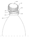
도 1은 실시형태에 따른 용기용 캡의 실시형태를 도시하는 3차원적인 개략도이다.
도 2a 내지 도 2g는 용기용 캡의 상이한 실시형태들을 도시하는 개략도이다.
도 3은 캡이 용기로부터 분리된 실시형태를 도시하는 3차원적인 개략도이다.
도 4는 구현예에 따른, 캡에 절개선을 새기기 위해서 사용되는 제조 시스템의 일부를 도시한다.
도 5는 구현예에 따른, 캡에 새겨진 절개선을 도시한다.
도 6은 구현예에 따른, 캡에 절개선을 새기기 위해서 사용되는 제조 시스템의 스핀들을 도시한다.
도 7은 구현예에 따른, 캡에 절개선을 새기기 위해서 사용되는 블레이드를 도시한다.
도 8, 도 9, 도 10, 도 11 및 도 12는 구현예에 따른, 캡에 절개선을 새기기 위해서 사용되는 블레이드를 위한 블레이드 패턴을 도시한다.
도 13, 도 14, 도 15, 도 16은 구현예에 따른, 절개선을 새기는 데 도움을 주기 위해서 스핀들 내에 배치되는 홈을 도시한다.
도 17, 도 18, 도 19, 도 20, 도 21, 도 22 및 도 23은 구현예에 따른, 용기로부터 제거된 후에 뒤집힌 상태로 용기에 대해서 유지될 수 있는 캡을 도시한다.
도 24, 도 25, 도 26 및 도 27은 용기로부터 제거된 후에 뒤집힌 상태로 용기에 대해서 유지될 수 있는 다른 캡을 도시한다.
도 28은 구현예에 따른, 캡 상의 대안적인 절개 패턴을 도시한다.
도 29, 도 30 및 도 31은 구현예에 따른, 캡 상의 다른 대안적인 절개 패턴을 도시한다.
도 32, 도 33 및 도 34은 구현예에 따른, 캡 상의 다른 대안적인 절개 패턴을 도시한다.
도 35, 도 36 및 도 37은 구현예에 따른, 캡 상의 다른 대안적인 절개 패턴을 도시한다.
도 38은 구현예에 따른, 캡 상의 다른 대안적인 절개 패턴을 도시한다.
도 39는 구현예에 따른, 캡 상의 다른 대안적인 절개 패턴을 도시한다.
도 40은 구현예에 따른, 캡 상의 다른 대안적인 절개 패턴을 도시한다.1 is a three-dimensional schematic diagram showing an embodiment of a cap for a container according to an embodiment.
2A to 2G are schematic diagrams showing different embodiments of a cap for a container.
3 is a three-dimensional schematic diagram illustrating an embodiment in which the cap has been removed from the container.
4 depicts a portion of a manufacturing system used to incise a cap, according to an embodiment.
5 shows an incision etched into a cap, according to an embodiment.
6 shows a spindle of a manufacturing system used to score a cap in accordance with an embodiment.
7 shows a blade used to incise a cap, according to an embodiment.
8, 9, 10, 11 and 12 show blade patterns for blades used to incise a cap, according to an embodiment.
13 , 14 , 15 , 16 show grooves disposed in the spindle to aid in scoring, according to an embodiment.
17 , 18 , 19 , 20 , 21 , 22 and 23 show a cap that can be held against a container in an inverted state after being removed from the container, according to an embodiment.
24, 25, 26 and 27 show another cap that can be held against a container in an inverted state after being removed from the container.
28 shows an alternative incision pattern on a cap, according to an embodiment.
29, 30 and 31 show other alternative incision patterns on the cap, according to embodiments.
32, 33 and 34 show other alternative incision patterns on the cap, according to embodiments.
35, 36 and 37 show another alternative incision pattern on the cap, according to an embodiment.
38 shows another alternative incision pattern on a cap, according to an embodiment.
39 shows another alternative incision pattern on a cap, according to an embodiment.
40 shows another alternative incision pattern on a cap, according to an embodiment.
도 1은 용기용 캡의 실시형태를 도시하는 3차원적인 개략도이다. 도 1에 도시된 바와 같이 본 예의 캡(10)은 상단 판(11) 및 원형 측벽(12)을 가지는 본체(1)를 포함한다. 원형 측벽(12)의 2개의 대향 측면들이 서로 원형으로 연결된다. 원형 측벽(12)의 하나의 주변부가 상단 판(11)의 하나의 표면에 연결되어 폐쇄 단부(1')를 형성한다. 폐쇄 단부(1')의 대향 측면에 위치되는 원형 측벽(12)의 다른 주변부는 (도 3에 도시된) 개방 단부(1")를 형성한다. 본 예의 캡(10)은 또한, 본체(1)의 개방 단부(1")에 위치되는 링 부재(2)를 포함한다. 링 부재(2)는, 캡(10)의 형성의 일부로서 형성될 수 있는 관통선에 의해서 본체(1)로부터 분리된다. 예를 들어, 관통선은, 캡(10)을 형성하는 사출 몰딩 프로세스 또는 다른 제조 프로세스의 일부로서 형성된다.1 is a three-dimensional schematic diagram showing an embodiment of a cap for a container. As shown in FIG. 1 , the
예를 들어, 관통선은 절개에 의해서 또한 형성될 수 있다. 이하의 설명에서 관통선이 종종 절개선으로 지칭되지만, 관통선은 절개 이외의 방법에 의해서 형성될 수 있다. 링 부재(2)는 본체(1)의 개방 단부(1")와 링 부재(2) 사이에 위치된 제1 절개선(3)에 의해서 본체(1)로부터 분리된다. 제1 절개선(3)은 복수의 연결 핀(31)을 포함한다. 제1 절개선(3)을 따라서 위치되는 복수의 연결 핀(31)은 제1 절개선(3)의 2개의 측면에서 본체(1) 및 링 부재(2)를 연결한다. 제1 절개선(3)의 2개의 단부들이 복수의 연결 부분(5)에 의해서 분리된다. 복수의 연결 부분(5)은 본체(1) 및 링 부재(2)를 함께 연결한다. 복수의 제2 절개선(4)이 복수의 연결 부분(5)의 하나의 측면에 위치된다. 복수의 제2 절개선(4)은 또한 본체(1) 또는 링 부재(2) 상에 위치된다. 복수의 제2 절개선(4)의 2개의 단부 및 그 자체는 연결되지 않는다. 복수의 제2 절개선(4)은 제1 절개선(3)과 중첩되지 않는다.For example, a through line may also be formed by incision. In the following description, the through line is often referred to as an incision, but the through line may be formed by a method other than an incision. The
도 2a에 도시된 바와 같이, 본 예에서, 복수의 연결 부분(5)은 제1 절개선(3)과 복수의 제2 절개선(4) 사이에 형성된다. 예를 들어, 복수의 연결 부분(5)의 형상은 특별히 제한되지 않는다. 복수의 연결 부분(5)의 형상은 제1 절개선(3) 및 복수의 연결 부분(5)의 측면들에 위치되는 복수의 제2 절개선(4)의 형상에 따라 달라진다. 본 예에서, 복수의 연결 부분(5)의 형상은 입방체이다(도 3에 도시됨). 예를 들어, 복수의 연결 부분(5)의 수량은 특별히 제한되지 않는다. 그러나, 본 예에서, 복수의 연결 부분(5)의 수량은 2개이다. 예를 들어, 복수의 연결 부분(5) 각각의 사이의 간격은 특별히 제한되지 않는다. 그러나, 본 예에서, 복수의 연결 부분(5)의 각각은 복수의 제2 절개선(4)의 부분에 의해서 분리된다.As shown in FIG. 2A , in this example, a plurality of connecting
예를 들어, 복수의 제2 절개선(4)의 수량은 특별히 제한되지 않는다. 그러나, 본 예에서, 복수의 제2 절개선(4)의 수량은 2개이다. 도 2a가 도시하는 바와 같이, 본체(1)만이 복수의 제2 절개선(4)을 갖는다. 2개의 제2 절개선(4) 중 하나는 제1 절개선(3)의 부분에 연결된다. 또한, 복수의 제2 절개선(4)의 부분은 제1 절개선(3)에 평행하다.For example, the number of the plurality of
예를 들어, 제1 절개선(3) 및 복수의 제2 절개선(4)은 특별히 제한되지 않는다. 제1 절개선(3) 및 복수의 제2 절개선(4)은 개별적으로, 예를 들어, 직선, 곡선, 연속선(polyline), 원호선(arc line), 또는 이들의 조합일 수 있다. 본 예에서, 제1 절개선(3)은 직선이다. 복수의 제2 절개선(4)은 또한 더 바람직하게는 L자형 선, S자형 선, Z자형 선, 또는 이들의 조합일 수 있다. 본 예에서, 복수의 제2 절개선(4)은 Z자형 선이다. 예를 들어, 복수의 제2 절개선(4)의 모서리(41)는 특별히 제한되지 않는다. 복수의 제2 절개선(4)의 모서리(41)는 예를 들어 곡선형 모서리, 모따기된 모서리, 날카로운 모서리, 또는 이들의 조합이다. 본 예에서, 복수의 제2 절개선(4)의 모서리(41)는 곡선형 모서리이다.For example, the
예를 들어, 제1 절개선(3) 및 복수의 제2 절개선(4)은 원형 측벽(12) 또는 링 부재(2)의 부분을 둘러싸나, 원형 측벽(12) 또는 링 부재(2)를 완전히 둘러싸지는 않는다. 원형 측벽(12) 또는 링 부재(2)를 둘러싸는 제1 절개선(3) 및 복수의 제2 절개선(4)의 길이는 특별히 제한되지 않는다. 본 예에서, 원형 측벽(12) 또는 링 부재(2)를 둘러싼 제1 절개선(3)의 길이는 원형 측벽(12) 또는 링 부재(2)를 둘러싼 복수의 제2 절개선(4)의 각각의 길이보다 길지만, 이는 구현예에 따라 다를 수 있다.For example, the
도 2b는 용기용 캡의 다른 실시형태를 도시하는 개략도이다. 본 예의 캡 및 도 1에 도시된 캡은, 복수의 제2 절개선(4) 및 도 2a에 도시된 복수의 제2 절개선(4)이 서로 반대라는 것을 제외하고 동일하다. 그럼에도 불구하고, 캡의 개방 방향 및 도 2a에 도시된 캡의 개방 방향은 여전히 동일하다(둘 다 반 시계 방향이고, 이는 도 2a 또는 도 2b에서 우측 방향의 회전이다).2B is a schematic diagram showing another embodiment of a cap for a container. The cap of this example and the cap shown in FIG. 1 are identical except that the plurality of
도 2c는 용기용 캡의 다른 실시형태를 도시하는 개략도이다. 본 예의 캡 및 도 1에 도시된 캡은, 링 부재(2)가 복수의 제2 절개선(4)을 포함하고 복수의 제2 절개선(4)이 링 부재(2)의 1/5미만을 둘러싸는 것을 제외하고 동일하다.2C is a schematic diagram showing another embodiment of a cap for a container. In the cap of this example and the cap shown in FIG. 1, the
도 2d는 용기용 캡의 다른 실시형태를 도시하는 개략도이다. 본 예의 캡과 도 1에 도시된 캡은, 복수의 제2 절개선(4)의 수량이 1개이고, 제2 절개선(4)이 본체(1)로부터 링 부재(2)까지 또는 링 부재(2)로부터 본체(1)까지 연장되고, 제2 절개선(4) 및 제1 절개선(3)이 연결되지 않으며, 제2 절개선(4)(Z자형 선)의 모서리(41)가 날카로운 모서리이고, 제2 절개선(4)이 원형 측벽(12)의 1/5 미만 및 링 부재(2)의 1/5 미만을 둘러싼다는 것을 제외하고 동일하다. 도 2e는 용기용 캡의 다른 실시형태를 도시하는 개략도이다. 본 예의 캡 및 도 1에 도시된 캡은, 복수의 제2 절개선(4)이 L자형 선이고, 이러한 L자형 선의 모서리(41)가 날카로운 모서리라는 것을 제외하고 동일하다.2D is a schematic diagram showing another embodiment of a cap for a container. In the cap of this example and the cap shown in FIG. 1, the number of the plurality of
도 2f는 용기용 캡의 다른 실시형태를 도시하는 개략도이다. 본 예의 캡 및 도 1에 도시된 캡은, 복수의 제2 절개선(4) 및 제1 절개선(3)이 서로 평행하지 않고 복수의 제2 절개선(4)이 S자형 선이라는 것을 제외하고 동일하다.2F is a schematic diagram showing another embodiment of a cap for a container. The cap of this example and the cap shown in FIG. 1 except that the plurality of
도 2g 용기용 캡의 다른 실시형태를 도시하는 개략도이다. 본 예의 캡 및 도 2e에 도시된 캡은, 복수의 제2 절개선(4)(L자형 선)의 모서리(41)가 곡선형 모서리이고 제2 절개선(4) 중 하나가 원형 측벽(12)의 1/2 미만을 둘러싼다는 것을 제외하고 동일하다.Figure 2g is a schematic diagram showing another embodiment of a cap for a container. In the cap of this example and the cap shown in FIG. 2E, the
도 3은 용기로부터 분리된 용기용 캡의 실시형태를 도시하는 3차원적인 개략도이고, 도시된 캡은 전술한 예들 중 어느 하나의 캡들 중 어느 하나 일 수 있다. 이하에서, 도 1에 도시된 캡을 이용하여, 캡의 실제 적용을 더욱 구체적으로 설명할 것이다.3 is a three-dimensional schematic diagram showing an embodiment of a cap for a container separated from a container, the cap shown being any one of the caps of any of the foregoing examples. Hereinafter, practical applications of the cap will be described in more detail using the cap shown in FIG. 1 .
예를 들어, 제공된 캡(10)은, 캡(10) 및 용기(20)가 함께 조립될 수만 있다면, 어떠한 특별한 제한도 없이 임의의 통상적인 용기와 함께 사용될 수 있다. 예를 들어, 캡(10)의 형상은 특별히 제한되지 않는다. 도 3에 도시된 바와 같이, 캡의 내부 측면은 원형이다. 예를 들어, 용기(20)의 형상이 또한 특별히 제한되지 않는다. 도 3에 도시된 바와 같이, 용기의 개구부(210)는 원형 개구부이다. 예를 들어, 용기(20)는 둥근 병 또는 둥근 캔이다. 도 3에 도시된 바와 같이, 용기(20)는 원형 개구부를 갖는 병이다.For example, the provided
캡(10)의 본체(1)는 용기의 개구부(210)의 개방 및 폐쇄를 제어할 수 있다. 도 3에 도시된 바와 같이, 본체(1)의 내부 측면은 나사산(110)을 갖는다. 용기의 개구부(210)의 외부 측면에 위치되는 상보적인 나사산 구조물(2100)을 통해서, 본체(1)가 회전에 의해서 용기의 개구부(210) 상에서 나사식으로 개방(반 시계 방향)될 수 있고 나사식으로 폐쇄(미도시)(시계 방향)될 수 있다. 예를 들어, 제공된 캡(10)의 본체(1)는 용기의 개구부(210) 상으로 나사식으로 폐쇄되고, 본체(1)의 폐쇄 단부(1')는 용기의 개구부(210)와 접경될 것이다. 한편, 본체(1)의 개방 단부(1")는 용기의 개구부(210)를 향해서 대면될 것이고 용기의 개구부(210)를 덮고 그에 피팅(fit)될 것이다. 결과적으로, 용기의 개구부(210)는 용기(20)가 밀봉되어 유지되는 폐쇄 상태가 된다.The
예를 들어, 제공된 캡(10)의 본체(1)의 외부 측면은 널링 부분(knurled portion)(120)을 가질 수 있다. 용기(20)를 개방하고자 할 때, 널링 부분(120)은 본체(1) 및 링 부재(2)를 회전시켜 분리하기 위한 힘을 인가하는 것을 용이하게 할 수 있다. 예를 들어, 실제 필요에 따라, 제공된 캡(10)의 본체(1)와 링 부재(2) 사이에 배치된 제1 절개선(3)은 본체(1) 및 링 부재(2)를 연결하는 복수의 연결 핀(31)을 가질 수 있다. 복수의 연결 핀(31)의 형상, 크기, 수량 및 간격은 특별히 제한되지 않는다. 제1 절개선(3)의 복수의 연결 핀(31)의 크기 및 수량이 작아지고 복수의 연결 핀(31)의 간격이 커질수록, 복수의 연결 핀(31)을 파괴하는 데 필요한 힘이 더 작아진다. 대조적으로, 제1 절개선(3)의 복수의 연결 핀(31)의 크기 및 수량이 커지고 복수의 연결 핀(31)의 간격이 작아질수록, 복수의 연결 핀(31)을 파괴하는 데 필요한 힘이 더 커진다. 본 예에서, 제1 절개선(3)의 복수의 연결 핀(31)의 크기 및 수량은 더 작고, 복수의 연결 핀(31)의 간격은 더 크다. 또한, 복수의 제2 절개선(4)은 복수의 연결 핀(31)을 포함하지 않는다. 그에 따라, 복수의 연결 핀(31)을 파괴하는 데 필요한 힘이 더 작다. 결과적으로, 사용자는 본체(1) 및 링 부재(2)를 더 용이하게 분리할 수 있다. 즉, 캡(10)은 용기의 개구부(210)로부터 보다 용이하게 개방될 수 있다.For example, the outer side of the
예를 들어, 캡(10)의 본체(1)가 용기의 개구부(210)로부터 나사식으로 개방될 때, 복수의 연결 부분(5)은 본체(1) 및 링 부재(2)를 함께 연결할 것이다. 링 부재(2)가 용기의 개구부의 볼록 부분(2200) 아래에 피팅되기 때문에, 링 부재(2)는 용기의 개구부(210)로부터 이탈되지 않을 것이다. 결과적으로, 용기의 개구부(210)로부터 분리된 본체(1)와 링 부재(2) 사이의 연결은 본체(1)가 용기(20)와 연결된 상태로 여전히 유지될 수 있게 할 것이다. 또한, 복수의 연결 부분(5)은 또한 본체(1)가 개방 상태로 유지되게 할 수 있다. 복수의 연결 부분(5)은 본체(1)가 용기의 개구부(210)와 간섭하는 것을 방지할 것이다. 복수의 연결 부분(5)은 또한 본체(1)의 자유 운동을 감소시킬 것이다. 결과적으로, 내용물을 용기(20)로부터의 비울 때, 복수의 연결 부분(5)은 본체(1)가 자유 운동으로 인해서 다른 물체와 접촉하는 것을 방지할 수 있다. 예를 들어, 용기(20)가 물병인 경우, 사용자가 물병의 물을 마실 때, 복수의 연결 부분(5)은 본체(1)가 사용자의 안면 및 임의의 신체 부분과 접촉하는 것을 방지할 것이다. 또한, 복수의 연결 부분(5)은, 본체(1)의 자유 운동을 감소시킴으로써, 본체(1) 내측의 잔류 내용물이 쉽게 유출되는 것도 방지할 수 있다. 그리고, 용기의 개구부(210)에 피팅된 링 부재(2)가 자유롭게 회전할 수 있음에 따라, 복수의 연결 부분(5)은 용이하게 뽑히지 않을 것이다.For example, when the
예를 들어, 제공된 캡은 당업계에 알려진 임의의 재료를 이용하여 제조될 수 있고, 캡의 재료는 예를 들어 플라스틱이다. 캡은 당업계에 알려진 임의의 프로세스에 의해서 제조될 수 있다. 예를 들어, 캡의 제조 프로세스는 사출 몰딩에 의한 것이다. 제1 절개선 및 복수의 제2 절개선은 임의의 알려진 방법에 의해서 형성될 수 있다. 전술한 모든 예에서, 제1 절개선 및 복수의 제2 절개선은 회전 컷팅에 의해서 형성되고, 절개는 컷팅 툴 또는 레이저 컷팅에 의해서 이루어진다.For example, the cap provided can be made using any material known in the art, and the material of the cap is, for example, plastic. The cap can be made by any process known in the art. For example, the manufacturing process of the cap is by injection molding. The first incision and the plurality of second incisions may be formed by any known method. In all the examples described above, the first incision line and the plurality of second incision lines are formed by rotary cutting, and the incision is made by a cutting tool or laser cutting.
도 4는 캡(73)에 절개선을 새기기 위해서 사용되는 제조 시스템(70)의 일부를 도시한다. 캡(73)은 스핀들(71)에 장착되고 기부(72)에 의해서 지지된다. 캡들(73)은, 도 5에 도시된 바와 같이, 블레이드(76)가 고정된 블레이드 지지 구조물(75)을 지날 때 회전된다. 블레이드(76)에 대해 캡(73)이 회전함으로써 캡(73)에 절개선이 새겨지게 된다.4 shows a portion of a
도 6은 스핀들 지지부(76)에 장착된 스핀들(71)을 도시한다.6 shows
도 7은, 캡(73)에 절개선을 생성하기 위해서 캡(73)이 블레이드(76)를 따라서 이동하는 경로(121)를 도시한다.7 shows a
도 8, 도 9, 도 10, 도 11 및 도 12는 캡에 절개선을 새기기 위해서 사용되는 블레이드를 위한 블레이드 패턴을 도시한다.Figures 8, 9, 10, 11 and 12 show blade patterns for blades used for incising caps.
도 8은 블레이드(131), 블레이드(132), 및 블레이드(133)를 이용하여 캡(73)에 절개선을 생성하는 블레이드 패턴(130)을 도시하고, 이는 캡을 링 섹션에 부착하는 각각의 캡의 연결 부분을 생성하게 된다. 블레이드(131)는 제1 블레이드 섹션, 및 제1 블레이드 섹션과 상이한 평면에 위치된 제2 블레이드 섹션을 포함한다. 제3 블레이드 섹션은 제1 블레이드 섹션과 제2 블레이드 섹션 사이에서 대각선 연결을 형성한다. 마찬가지로, 블레이드(132)는 제1 블레이드 섹션, 및 제1 블레이드 섹션과 상이한 평면에 위치된 제2 블레이드 섹션을 포함한다. 제1 블레이드 섹션은 제1 블레이드 섹션 블레이드(131)와 동일한 평면에 위치된다. 제2 블레이드 섹션은 제2 블레이드 섹션 블레이드(131)와 동일한 평면에 위치된다. 제3 블레이드 섹션은 제1 블레이드 섹션과 제2 블레이드 섹션 사이에서 대각선 연결을 형성한다. 블레이드(133)는 블레이드(131)의 제1 블레이드 섹션과 동일한 평면에 위치된다. 캡이 용기에 장착될 때, 연결 부분은, 전술한 바와 같이 캡이 용기 개구부로부터 제거된 후에도, 캡이 링에 부착되어 용기에 부착된 상태를 유지하도록 보장한다. 블레이드(131), 블레이드(132) 및 블레이드(133)의 노치(notch)는 캡과 링 섹션 사이의 가교형 연결 부분을 형성한다. 가교형 연결 부분은, 캡이 용기에 장착되고 캡을 돌려 열어서 용기가 개방될 때 파괴된다.8 shows a
도 9는 블레이드(141), 블레이드(142), 블레이드(143), 블레이드(144), 블레이드(145), 블레이드(146) 및 블레이드(147)를 이용하여 캡(73)에 절개선을 생성하는 블레이드 패턴(140)을 도시하고, 이는 캡을 링 섹션에 부착하는 각각의 캡의 연결 부분을 생성하게 된다. 블레이드(141, 144 및 147)는 모두 제1 평면에 위치된다. 블레이드(143 및 146)는 모두 제2 평면에 위치된다. 블레이드(142 및 145)는 모두 제1 평면과 제2 평면 사이의 제3 평면에 위치된다. 블레이드(142 및 145)는 복수의 블레이드 중 다른 블레이드보다 작은 절개부를 만든다. 블레이드(142 및 145)는 제1 평면과 제2 평면 사이에 대각선으로 배향된다. 대안적으로, 블레이드(142) 및 블레이드(145)는, 제1 평면과 제2 평면 사이에 위치될 때, 수평 또는 수직으로 배향될 수 있다.9 is a method of creating an incision in a
캡이 용기에 장착될 때, 연결 부분은, 전술한 바와 같이 캡이 용기 개구부로부터 제거된 후에도, 캡이 링에 부착되어 용기에 부착된 상태를 유지하도록 보장한다. 블레이드(141), 블레이드(143), 블레이드(146) 및 블레이드(147)의 노치는 캡과 링 섹션 사이의 가교형 연결 부분을 형성한다. 가교형 연결 부분은, 캡이 용기에 장착되고 캡을 돌려 열어서 용기가 개방될 때 파괴된다.When the cap is mounted to the container, the connection portion ensures that the cap remains attached to the container by being attached to the ring even after the cap has been removed from the container opening as described above. The notches of
도 10은 블레이드(151), 블레이드(152), 블레이드(153), 블레이드(154) 및 블레이드(155)를 이용하여 캡(73)에 절개선을 생성하는 블레이드 패턴(150)을 도시하고, 이는 캡을 링 섹션에 부착하는 각각의 캡의 연결 부분을 생성하게 된다. 블레이드(151)는 제1 평면에 위치되고, 제1 갭 및 제2 갭을 갖는다. 블레이드(153) 및 블레이드(155)는 모두 제2 평면에 위치된다. 블레이드(152) 및 블레이드(154)는 모두 제1 평면과 제2 평면 사이의 제3 평면에 위치된다. 블레이드(152)는 제1 갭 부근에 위치되고, 블레이드(154)는 제2 갭 부근에 위치된다. 블레이드(152 및 154)는 이러한 구성의 다른 블레이드보다 작은 절개부를 만든다. 블레이드(152 및 154)는 제1 평면과 제2 평면 사이에서 대각선으로 배향된다. 대안적으로, 블레이드(152) 및 블레이드(154)는, 제1 평면과 제2 평면 사이에 위치될 때, 수평 또는 수직으로 배향될 수 있다. 캡이 용기에 장착될 때, 연결 부분은, 전술한 바와 같이 캡이 용기 개구부로부터 제거된 후에도, 캡이 링에 부착되어 용기에 부착된 상태를 유지하도록 보장한다. 블레이드(151), 블레이드(153) 및 블레이드(155)의 노치는 캡과 링 섹션 사이의 가교형 연결 부분을 형성한다. 가교형 연결 부분은, 캡이 용기에 장착되고 캡을 돌려 열어서 용기가 개방될 때 파괴된다.FIG. 10 shows a
도 11은 블레이드(161), 블레이드(62), 블레이드(163), 블레이드(164), 블레이드(165), 블레이드(166) 및 블레이드(167)를 이용하여 캡(73)에 절개선을 생성하는 블레이드 패턴(160)을 도시하고, 이는 캡을 링 섹션에 부착하는 각각의 캡의 연결 부분을 생성하게 된다. 블레이드(163, 164 및 146)는 모두 제1 평면에 위치된다. 블레이드(165 및 167)는 모두 제2 평면에 위치된다. 블레이드(161 및 162)는 모두 제1 평면과 제2 평면 사이의 제3 평면에 위치된다. 블레이드(161 및 162)는, 복수의 블레이드 중 다른 블레이드보다 작은 절개부를 만든다. 블레이드(161 및 162)는 제1 평면과 제2 평면 사이에서 대각선으로 배향된다. 대안적으로, 블레이드(161) 및 블레이드(162)는, 제1 평면과 제2 평면 사이에 위치될 때, 수평 또는 수직으로 배향될 수 있다. 캡이 용기에 장착될 때, 연결 부분은, 전술한 바와 같이 캡이 용기 개구부로부터 제거된 후에도, 캡이 링에 부착되어, 용기에 부착된 상태를 유지하도록 보장한다. 블레이드(163), 블레이드(164), 블레이드(165), 블레이드(166) 및 블레이드(167) 내의 노치는 캡과 링 섹션 사이의 가교형 연결 부분을 형성한다. 가교형 연결 부분은, 캡이 용기에 장착되고 캡을 돌려 열어서 용기가 개방될 때 파괴된다.11 is a method of creating an incision in a
도 12는 제1 평면 내의 블레이드(171), 블레이드(172) 및 블레이드(173)를 이용하는 블레이드 패턴(170)을 도시한다. 블레이드(174) 및 블레이드(175)는 제2 평면 내에 위치된다. 블레이드(176) 및 블레이드(177)는 제1 평면과 제2 평면 사이에서 수평으로 배향된다. 대안적으로, 블레이드(176) 및 블레이드(177)는, 제1 평면과 제2 평면 사이에 위치될 때, 대각선 또는 수직으로 배향될 수 있다. 캡이 용기에 장착될 때, 연결 부분은, 전술한 바와 같이 캡이 용기 개구부로부터 제거된 후에도, 캡이 링에 부착되어 용기에 부착된 상태를 유지하도록 보장한다. 블레이드(163), 블레이드(164), 블레이드(165), 블레이드(166) 및 블레이드(167)의 노치는 캡과 링 섹션 사이의 가교형 연결 부분을 형성한다. 가교형 연결 부분은, 캡이 용기에 장착되고 캡을 돌려 열어서 용기가 개방될 때 파괴된다.FIG. 12 shows a
스핀들은, 캡에 절개선을 새기는 데 도움을 주기 위해서 블레이드의 위치를 반영하는 홈을 포함할 수 있다. 예를 들어, 도 13은, 블레이드 또는 블레이드 패턴의 모든 블레이드 연부를 수용하기에 충분한 너비의 홈(182)을 포함하는 스핀들 헤드(181)를 갖는 스핀들(180)을 도시한다.The spindle may include grooves that reflect the position of the blades to aid in scoring the cap. For example, FIG. 13 shows a
도 14는, 블레이드 패턴의 블레이드 또는 블레이드 복합체의 하나의 블레이드 연부를 수용하기에 충분한 너비를 각각 갖는 홈(202) 및 홈(203)을 포함하는 스핀들 헤드(201)를 갖는 스핀들(200)을 도시한다. 도 14에 도시된 구현예에서, 각각의 "수평" 블레이드 연부는 그 자체의 매칭 홈(matching groove)을 가지며, 수직 또는 대각선 블레이드 또는 블레이드 부분을 위한 홈은 없다.14 shows a
도 15는, 블레이드(196)의 블레이드 연부로서 표시된 블레이드 또는 블레이드 부분의 하나의 블레이드 연부를 수용하기에 충분한 너비를 각각 갖는 홈(192), 홈(193), 홈(194), 및 홈(195)을 포함하는 스핀들 헤드(191)를 갖는 스핀들(190)을 도시한다. 도 15에 도시된 구현예에서, 각각의 "수평" 블레이드는 그 자체의 매칭 홈을 가지며, 각각의 수직 또는 대각선 블레이드 또는 블레이드 부분은 그 자체의 매칭 홈을 갖는다.15 shows
도 16은, 블레이드 패턴의 하나의 블레이드 또는 하나의 블레이드 부분을 수용하기에 충분한 너비를 각각 갖는 홈(291), 홈(292) 및 홈(293)을 포함하는 스핀들 헤드(294)를 갖는 스핀들(290)을 도시한다. 예를 들어, 블레이드 조합(295)은 블레이드 연부(296), 블레이드 연부(297) 및 블레이드 연부(298)를 갖는다. 예를 들어, 홈(292)은 도 10에 도시된 대각선 블레이드(152 및 154)와 같은 대각선 블레이를 허용하기 위해서 존재한다.16 shows a spindle having a spindle head 294 comprising
도 17, 도 18, 도 19, 도 20, 도 21, 도 22 및 도 23은 용기(300)로부터 제거된 후의 캡(301)이 뒤집힌 상태로 용기(300)에 대해서 유지될 수 있는 것을 도시한다. 구체적으로, 도 17에서, 캡(301)은 용기(300)에 고정되어 도시되어 있다. 제1 절개부(303) 및 제2 절개부(304)가 캡(301)과 링 부재(302) 사이에서 연결 부분(305) 및 연결 부분(306)을 형성한다. 도 17에 도시된 실시형태에서, 연결 부분(305)이 링 부재(302)에 연결된 위치와 연결 부분(306)이 캡(301)에 연결된 위치 사이에 영역(307)이 존재한다. 캡(301)이 용기(300)로부터 제거될 때, 연결 부분(305) 및 연결 부분(306)에 의해서 캡(301)이 용기(300)에 대해서 뒤집힌 상태로 유지될 수 있도록, 영역(307), 제1 절개부(303) 및 제2 절개부(304)의 치수 모두가 연결 부분(305) 크기 및 연결 부분(306) 크기에 따라 달라지기 때문에, 캡(301)의 높이 및 캡(301)의 직경은 영역(307)의 길이 및 심지어 영역(307)이 존재하는지 여부에 영향을 미친다.17, 18, 19, 20, 21, 22 and 23 show that the
뒤집힌 상태로, 캡(301)의 상단 표면(308)은, 상단 표면(308)이 용기(300)에 대면되는 상태로 유지된다. 연결 부분(305)의 탄성 및 연결 부분(306)의 탄성이, 사용자가 연결 부분(305) 및 연결 부분(306)을 연신시키는 것에 의해 캡(301)이 용기(300)에 대해 뒤집힌 상태로 이동되는 것을 허용하고 이어서 사용자가 용기의 내용물을 음용하는 동안 연결 부분(305)의 탄성 및 연결 부분(306)이 탄성이 캡(301)을 용기(300)에 대해서 뒤집힌 상태로 유지하도록, 연결 부분(305)의 길이 및 연결 부분(306)의 길이가 선택된다.When inverted, the
사용자가 일시적으로 용기(300)의 내용물 음용을 끝냈 때, 연결 부분(305)의 탄성 및 연결 부분(306)의 탄성으로 인해 사용자가 캡(301)을 뒤집힌 상태로부터 초기 개방 상태로 이동시킬 수 있고, 그러한 초기 개방 상태로부터 캡(301)을 용기(300) 상으로 다시 돌려서 닫을 수 있다. 캡이 밀어 뒤집는 설계(flip top design)를 가지는 경우에, 캡을 용기 상으로 다시 스냅 결합시키는 것에 의해서 캡이 재부착될 수 있다.When the user temporarily finishes drinking the contents of the
도 18은 캡(301)이 용기(300)로부터 돌려 열려진 후의 캡(301)을 도시한다. 연결 부분(305) 및 연결 부분(306)은 캡(301)을 링 부재(302)에 대해서 유지한다. 캡(301)의 상단 표면(308)은 용기(300)로부터 멀어지는 쪽을 향한다.18 shows the
도 19는 캡(301)이 용기(300)로부터 돌려 열려진 후의 캡(301)의 확대도를 도시한다. 캡(301)의 제거 시에 캡(301)의 립(lip)(310)이 노출된다. 연결 부분(305) 및 연결 부분(306)은 캡(301)을 링 부재(302)에 대해서 유지한다. 캡(301)의 상단 표면(308)은 용기(300)로부터 멀어지는 쪽을 향한다.19 shows an enlarged view of the
도 20은, 캡(301)이 용기(300)로부터 밀어서 개방된, 캡(301)의 확대도를 도시한다. 연결 부분(305) 및 연결 부분(306)은 캡(301)을 링 부재(302)에 대해서 유지한다. 충분한 힘이 캡(301)에 인가될 때까지, 연결 부분(305) 및 연결 부분(306)은 캡(301)이 용기(300)의 립(310)을 지나서 뒤집히게 할 정도로 충분히 길지는 않다. 연결 부분(305) 및 연결 부분(306)이 짧기 때문에, 립(310)은, 상단 표면(308)이 용기(300)에 대면되는 뒤집힌 상태로 캡(301)이 배치되는 것을 방해한다. 사용자가 압력을 더 가하면, 연결 부분(305) 및 연결 부분(306)은, 캡(301)이 립(310)을 지나서 뒤집히게 할 정도로 충분히 연신되고, 그에 따라 캡(301)은, 상단 표면(308)이 용기(300)에 대면되는 뒤집힌 상태로 있게 된다.20 shows an enlarged view of the
도 21 및 도 22는, 상단 표면(308)이 용기(300)에 대면되는 뒤집힌 상태의 캡(301)을 도시한다. 연결 부분(305) 및 연결 부분(306)의 탄성은, 상단 표면(308)이 용기(300)에 대면되는 뒤집힌 상태로 캡(301)을 유지한다.21 and 22 show the
도 23은, 연결 부분(305) 및 연결 부분(306)의 탄성이, 상단 표면(308)이 용기(300)에 대면되는 뒤집힌 상태로 캡(301)을 유지하는 것을 도시하는 상면도이다.FIG. 23 is a top view showing that the elasticity of connecting
캡의 높이 및 직경은, 캡의 상단 표면이 용기에 대면되는 뒤집힌 상태로 캡이 배치되고 유지될 수 있게 하는 데 필요한 연결 부분의 길이를 결정한다. 도 24 및 도 25는 용기(400)의 립(410) 위에 피팅되는 크기의 캡(401)을 갖는 용기(400)를 도시한다.The height and diameter of the cap determine the length of the joint required to allow the cap to be placed and held in an inverted condition with the top surface of the cap facing the container. 24 and 25 show a
도 24 및 도 25는 용기(400)로부터 돌려 열려지고 밀어서 개방된 캡(401)을 도시한다. 연결 부분(405) 및 연결 부분(406)은 캡(401)을 링 부재(402)에 대해서 유지한다. 충분한 힘이 캡(401)에 인가될 때까지, 연결 부분(405) 및 연결 부분(406)은 캡(401)이 용기(400)의 립(410), 링 부재(402) 및 용기(400)의 융기부(411)를 지나서 뒤집히게 할 정도로 충분히 길지는 않다. 연결 부분(405) 및 연결 부분(406)이 짧기 때문에, 립(410), 링 부재(402) 및 융기부(411)는, 상단 표면(408)이 용기(400)에 대면되는 뒤집힌 상태로 캡(401)이 배치되는 것을 방해한다. 사용자가 압력을 더 가하면, 연결 부분(405) 및 연결 부분(406)은, 캡(401)이 립(410), 링 부재(402) 및 융기부(411)를 지나서 뒤집히게 할 정도로 충분히 연신되고, 그에 따라 캡(401)은, 상단 표면(408)이 용기(400)에 대면되는 뒤집힌 상태로 있게 된다.24 and 25 show the
도 26은, 상단 표면(408)이 용기(400)에 대면되는 뒤집힌 상태의 캡(401)을 도시한다. 연결 부분(405) 및 연결 부분(406)의 탄성은, 상단 표면(408)이 용기(400)에 대면되는 뒤집힌 상태로 캡(401)을 유지한다.26 shows the
도 27은, 연결 부분(405) 및 연결 부분(406)의 탄성이, 상단 표면(408)이 용기(400)에 대면되는 뒤집힌 상태로 캡(401)을 유지하는 것을 도시하는 상면도이다.27 is a top view showing that the resiliency of
절개부들이 반전될 수 있다. 예를 들어, 도 28에서, 캡(501)은 용기(500)에 고정되어 도시되어 있다. 제1 절개부(503) 및 제2 절개부(504)가 캡(501)과 링 부재(502) 사이에서 연결 부분(505) 및 연결 부분(506)을 형성한다. 도 17에 도시된 실시형태에서, 연결 부분(505)이 링 부재(502)에 연결된 위치와 연결 부분(506)이 캡(501)에 연결된 위치 사이에 영역(507)이 존재한다. 캡(501)이 용기(500)로부터 제거될 때, 연결 부분(505) 및 연결 부분(506)에 의해서 캡(501)이 용기(500)에 대해서 뒤집힌 상태로 유지될 수 있도록, 영역(507), 제1 절개부(503) 및 제2 절개부(504)의 치수 모두가 연결 부분(505) 크기 및 연결 부분(506) 크기에 따라 달라지기 때문에, 캡(501)의 높이 및 캡(501)의 직경은 영역(507)의 길이 및 심지어 영역(507)이 존재하는지 여부에 영향을 미친다.The incisions may be inverted. For example, in FIG. 28 ,
절개부가 캡 내로 연장되어, 캡이 뒤집힌 상태로 더 용이하게 뒤집히게 할 수 있다. 예를 들어, 도 29는 용기(600) 상의 캡(601)을 도시한다. 도 30은, 용기(600)로부터 돌려 열려지고 밀어서 개방된 캡(601)을 도시한다. 연결 부분(605) 및 연결 부분(606)은 캡(601)을 링 부재(602)에 대해서 유지한다. 연결 부분(605)을 형성하기 위한 절개부가 캡(601) 내로 연장된다. 연결 부분(606)을 형성하기 위한 절개부가 캡(601) 내로 연장된다.An incision may extend into the cap to make it easier to turn the cap into an inverted condition. For example, FIG. 29 shows cap 601 on
충분한 힘이 캡(601)에 인가될 때까지, 연결 부분(605) 및 연결 부분(606)은 캡(601)이 용기의 립(610)을 지나 뒤집히게 할 정도로 충분히 길지는 않다. 사용자가 압력을 더 가하면, 연결 부분(605) 및 연결 부분(606)은 캡(601)이 립을 지나 뒤집힐 정도로 충분히 연신된다.Until sufficient force is applied to cap 601, connecting
도 31은, 상단 표면(608)이 하향 방향으로 대면되는 뒤집힌 상태의 캡(601)을 도시한다. 연결 부분(605) 및 연결 부분(606)의 탄성은, 상단 표면(608)이 하향 대면되는 뒤집힌 상태로 캡(601)을 유지한다. 노치(612) 하단부의 연결 부분(605)과 캡(601)의 연결 위치 및 노치(613) 하단부의 연결 부분(606)과 캡(601)의 연결 위치는, 캡(601)을 뒤집힌 상태로 배치하기 위한 연결 부분(605) 및 연결 부분(606)의 더 적은 연신을 초래한다. 이는, 캡(601)을 뒤집힌 상태로 배치하는 데 있어서 더 적은 힘이 필요하고 따라서 그러한 배치가 더 용이하다는 것을 의미한다. 대안적으로, 캡(601)은, 상단 표면(608)이 용기(600)에 대면되는 뒤집힌 상태로 배치될 수 있다.31 shows the
캡을 뒤집힌 상태로 유지하는 형상으로, 캡으로부터 연장되는 탭이 부가될 수 있다. 예를 들어, 도 32는 용기(700) 상의, 상단 표면(708)을 갖춘 캡(701)을 도시한다. 2개의 절개선은 도시된 바와 같이 연결 부분(705), 연결 부분(706), 및 탭(710)의 윤곽을 나타낸다. 탭(710)은 링 부재(702)의 갭(711) 내로 연장된다.A tab extending from the cap may be added, in a shape that holds the cap in an inverted state. For example, FIG. 32 shows a
도 33은, 용기(700)로부터 돌려 열려지고 밀어서 개방된 캡(701)을 도시한다. 연결 부분(705) 및 연결 부분(706)은 캡(701)을 링 부재(702)에 대해서 유지한다.33 shows a
도 34는, 상단 표면(708)이 하향 방향으로 대면되는 뒤집힌 상태의 캡(701)을 도시한다. 연결 부분(705) 및 연결 부분(706)의 탄성뿐만 아니라 탭(710)의 형상 및 위치는, 상단 표면(708)이 하향 대면되는 뒤집힌 상태로 캡(701)을 유지한다.34 shows the
도 35는 제조를 단순화하고 작업을 개선하는 개선된 절개 패턴을 도시한다. 예를 들어, 도 35는 용기(800) 상의 캡(801)을 도시한다. 캡(801)은 상단 표면(808) 및 원형 측벽(813)을 갖는다. 2개의 절개부는 도시된 바와 같이 연결 부분(805), 연결 부분(806), 탭(810), 탭(812), 및 탭(816)의 윤곽을 나타낸다. 제1 절개부는 절개 섹션(821), 절개 섹션(822), 절개 섹션(823), 절개 섹션(824), 절개 섹션(825), 절개 섹션(826), 및 절개 섹션(827)을 포함한다. 제2 절개부는 절개 섹션(828), 절개 섹션(829), 절개 섹션(830), 절개 섹션(831), 절개 섹션(832), 절개 섹션(833), 및 절개 섹션(834)을 포함한다. 연결 핀들이 도 35에 구체적으로 도시되지 않았지만, 다른 구현예에서 전술된 바와 같이, 이들은 제1 절개부 및 제2 절개부를 따라서 포함될 수 있다.35 shows an improved incision pattern that simplifies manufacturing and improves operation. For example, FIG. 35 shows a
연결 부분(805), 연결 부분(806), 탭(810), 탭(812), 및 탭(816)은 모두 동일한 2개의 절개 평면들 사이에 형성된다. 제1 절개 평면은 제1 절개부의 절개 섹션(821) 및 절개 섹션(827)에 의해서 그리고 제2 절개부의 절개 섹션(828) 및 절개 섹션(832)에 의해서 정의되고, 이들 모두는 제1 절개 평면에 배치된 절개 섹션이다. 제2 절개 평면은 제1 절개부의 절개 섹션(823) 및 절개 섹션(825)에 의해서 그리고 제2 절개부의 절개 섹션(830) 및 절개 섹션(834)에 의해서 정의되고, 이들 모두는 제2 절개 평면에 배치된 절개 섹션이다.
연결 부분(806)의 경계는 제1 절개부의 절개 섹션(822) 및 절개 섹션(823)에 의해서 그리고 제2 절개부의 절개 섹션(828) 및 절개 섹션(829)에 의해서 형성된다.The boundary of the connecting
연결 부분(805)의 경계는 제1 절개부의 절개 섹션(826) 및 절개 섹션(827)에 의해서 그리고 제2 절개부의 절개 섹션(833) 및 절개 섹션(834)에 의해서 형성된다.The boundary of the connecting
탭(810)의 경계는 제2 절개부의 절개 섹션(829), 절개 섹션(830) 및 절개 섹션(831)에 의해서 형성된다. 탭(812)의 경계는 제1 절개부의 절개 섹션(824), 절개 섹션(825) 및 절개 섹션(826)에 의해서 형성된다. 탭(816)의 경계는 제2 절개부의 절개 섹션(832), 절개 섹션(833) 및 절개 섹션(834)에 의해서 형성된다.The boundary of the
도 35에 도시된 절개 패턴은 도 32에 도시된 절개부에 비해 몇몇 장점을 갖는다. 예를 들어, 도 32에 도시된 바와 같이, 연결 부분(705) 및 연결 부분(706)이 2개의 절개 평면들 사이에 형성되지만, 탭(710)은 이러한 절개 평면 아래에서 연장되고, 이는 블레이드의 다른 평면이 캡(801)의 제조를 위해서 사용될 것을 요구한다.The incision pattern shown in FIG. 35 has several advantages over the incision shown in FIG. 32 . For example, as shown in FIG. 32 , connecting
이는, 블레이드(141, 144 및 147) 모두가 제1 평면 상에 위치되고, 블레이드(143 및 146) 모두가 제2 평면 상에 위치되고, 블레이드(142 및 145) 모두가 제3 평면 상에 위치된 것을 보여주는 도 9에 의해서 이해될 수 있다. 도 9에 도시된 블레이드 구성과 마찬가지로, 도 32에 도시된 절개 패턴은 블레이드들이 3개의 상이한 평면들에 배치될 것을 요구한다. 그러나, 도 35에 도시된 절개 패턴은 블레이드들의 평면들 중 하나를 제거할 수 있게 하고, 그에 따라 블레이드들의 평면들 중 2개만이 필요하다.This means that
절개 패턴의 다른 장점은 도 36을 고려함으로써 이해될 수 있다. 도 36은, 용기(800)로부터 돌려 열려지고 밀어서 개방된 캡(801)을 도시한다. 연결 부분(805) 및 연결 부분(806)은 캡(801)을 링 부재(802)에 대해서 유지한다. 탭(810)의 제거는 링 부재(802) 내에 갭(811)을 남긴다. 탭(812)의 제거는 링 부재(802) 내에 갭(813)을 남긴다.Another advantage of the incision pattern can be understood by considering FIG. 36 . 36 shows the
도 36에 도시된 바와 같이, 연결 부분(806)의 양 측면은, 제1 절개부의 절개 섹션(823)에 의해서 그리고 제2 절개부의 절개 섹션(830)에 의해서 정의된 바와 같은 제2 절개 평면으로부터 연장된다. 마찬가지로, 연결 부분(805)의 양 측면은, 제1 절개부의 절개 섹션(825)에 의해서 그리고 제2 절개부의 절개 섹션(834)에 의해서 경계 지어진 바와 같은 제2 절개 평면으로부터 연장된다.As shown in FIG. 36 , both sides of the connecting
그러나, 도 33에 도시된 절개 패턴에서, 연결 부분(705) 및 연결 부분(706)의 측면들은 상이한 절개 평면들로부터 연장된다. 이는 연결 부분(705) 및 연결 부분(706)의 미관 및 최적의 기능에 영향을 미친다. 최적의 기능이 도 37에서 추가로 예시된다.However, in the incision pattern shown in FIG. 33 , the side surfaces of
도 37은, 상단 표면(808)이 하향 방향으로 대면되는 뒤집힌 상태의 캡(801)을 도시한다. 뒤집힌 상태로, 캡(801)의 탭(810)이 링 부재(802)의 탭(816) 상에 놓이도록 정렬된다. 연결 부분(805) 및 연결 부분(806)의 탄성 더하기 탭(810)의 형상 및 위치는, 상단 표면(808)이 하향 대면되는 뒤집힌 상태로 캡(801)을 유지한다. 도 37에 도시된 바와 같이, 연결 부분(806)의 양 측면이 제2 절개 평면으로부터 연장되기 때문에, 연결 부분(806)은 링 부재(802)의 교차 지역(814)에서 접혀서 이로부터 편평하게 연장될 수 있다. 마찬가지로, 연결 부분(805)의 양 측면이 제2 절개 평면으로부터 연장되기 때문에, 연결 부분(805)은 링 부재(802)의 교차 지역(815)에서 접혀서 이로부터 편평하게 연장될 수 있다. 이를, 연결 부분(706)의 측면들이 2개의 상이한 절개 평면들 상에서 링 부재(702)로부터 연장되어, 연결 부분(706)이 링 부재(702)에 연결되는 루프화 효과(looping effect)를 초래하는 도 34와 비교한다. 마찬가지로, 연결 부분(705)의 측면들이 2개의 상이한 절개 평면들 상에서 링 부재(702)로부터 연장되어, 연결 부분(705)이 링 부재(702)에 연결되는 루프화 효과를 초래한다. 이러한 루프화 효과는 캡(701)을 제거하고 뒤집는 데 필요한 노력을 증가시킨다. 이러한 장력원을 제거하는 것은 도 35 및 도 37에 도시된 설계에 의해서 달성된다.37 shows the
도 36에 도시된 시스템에서 (예를 들어, 돌려 열려짐에 의해서) 캡(801)을 상승시킬 때 장력이 감소되는 다른 방식은, 캡(808)이 링 부재(802)로부터 분리되고 상승되는 동안 연결 부분(805) 및 연결 부분(806)이 평행한 각도들을 갖는 것이다. 연결 부분(805) 및 연결 부분(806)의 평행 각도의 이러한 특징이 또한 도 3, 도 18 및 도 33에 도시된 것과 같은 다른 실시형태에서 나타난다.Another way in the system shown in FIG. 36 is that the tension is reduced when lifting the cap 801 (eg, by screwing it open) while the
또한, 연결 부분(806) 및 연결 부분(805) 모두가 링 부재(802) 상에서 접혀서 그로부터 편평하게 연장되기 때문에, 이는 링 부재가 감소된 폭을 가질 수 있게 하여, 용기(800)에 대한 뒤집힌 캡(801)의 위치를 낮출 수 있다. 그에 따라, 도 37에 도시된 바와 같이, 탭(810)은 도 34에 도시된 탭(710)에 비해서 더 낮은 프로파일을 가질 수 있다. 탭(810)의 감소된 프로파일(즉, 더 낮은 높이)은 뒤집히거나 역으로 뒤집힐 때 연결 부분(805) 및 연결 부분(806)이 더 짧아지게 하고, 그에 따라 연결 부분(805) 및 연결 부분(806) 상의 장력이 더 작아질 수 있게 한다.Additionally, since both connecting
도 35에 도시된 절개 패턴이 전술한 모든 장점을 가능하게 하지만, 유사한 절개 패턴을 이용하여 동일한 최종 결과를 또한 달성할 수 있다.Although the ablation pattern shown in FIG. 35 enables all of the advantages described above, similar ablation patterns can also be used to achieve the same end result.
예를 들어, 도 38는 용기(840) 상의 캡(841)을 도시한다. 캡(841)은 상단 표면(848) 및 원형 측벽(843)을 갖는다. 2개의 절개부는 도시된 바와 같이 연결 부분(845), 연결 부분(846), 탭(865), 탭(866), 및 탭(867)의 윤곽을 나타낸다. 제1 절개부는 절개 섹션(851), 절개 섹션(852), 절개 섹션(853), 절개 섹션(854), 절개 섹션(855), 절개 섹션(856), 및 절개 섹션(857)을 포함한다. 제2 절개부는 절개 섹션(858), 절개 섹션(859), 절개 섹션(860), 절개 섹션(861), 절개 섹션(862), 절개 섹션(863), 및 절개 섹션(864)을 포함한다. 연결 핀들이 도 38에 구체적으로 도시되지 않았지만, 다른 구현예에서 전술된 바와 같이, 이들은 제1 절개부 및 제2 절개부를 따라서 포함될 수 있다.For example, FIG. 38 shows cap 841 on
연결 부분(845), 연결 부분(846), 탭(865), 탭(866), 및 탭(867)은 모두 동일한 2개의 절개 평면들 사이에 형성된다. 제1 절개 평면은 제1 절개부의 절개 섹션(851) 및 절개 섹션(855)에 의해서 그리고 제2 절개부의 절개 섹션(858) 및 절개 섹션(862)에 의해서 정의되고, 이들 모두는 제1 절개 평면에 배치된 절개 섹션이다. 제2 절개 평면은 제1 절개부의 절개 섹션(853) 및 절개 섹션(857)에 의해서 그리고 제2 절개부의 절개 섹션(864) 및 절개 섹션(867)에 의해서 정의되고, 이들 모두는 제2 절개 평면에 배치된 절개 섹션이다.
연결 부분(846)의 경계는 제1 절개부의 절개 섹션(851) 및 절개 섹션(852)에 의해서 그리고 제2 절개부의 절개 섹션(863) 및 절개 섹션(864)에 의해서 형성된다.The boundary of the connecting
연결 부분(845)의 경계는 제1 절개부의 절개 섹션(856) 및 절개 섹션(857)에 의해서 그리고 제2 절개부의 절개 섹션(858) 및 절개 섹션(859)에 의해서 형성된다.The boundary of the connecting
탭(865)의 경계는 제2 절개부의 절개 섹션(861), 절개 섹션(862) 및 절개 섹션(863)에 의해서 형성된다. 탭(866)의 경계는 제2 절개부의 절개 섹션(859), 절개 섹션(860) 및 절개 섹션(861)에 의해서 형성된다. 탭(867)의 경계는 제1 절개부의 절개 섹션(852), 절개 섹션(853) 및 절개 섹션(854)에 의해서 형성된다.The boundary of the
뒤집힌 상태로, 캡(841)의 탭(865)이 링 부재(842)의 탭(860) 상에 놓이도록 정렬된다. 일부 구현예에서, 절개 섹션(852, 853 및 854)을 생략하고 절개 섹션(851)을 연장시켜 절개 섹션(855)과 직접 연결하는 것에 의해서, 탭(867)이 생략될 수 있다.When inverted, the
다른 예에서, 도 39는 용기(870) 상의 캡(871)을 도시한다. 캡(871)은 상단 표면(878) 및 원형 측벽(873)을 갖는다. 2개의 절개부는 도시된 바와 같이 연결 부분(875), 연결 부분(876), 탭(895), 탭(896), 및 탭(897)의 윤곽을 나타낸다. 제1 절개부는 절개 섹션(881), 절개 섹션(882), 절개 섹션(883), 절개 섹션(884), 절개 섹션(885), 및 절개 섹션(886)을 포함한다. 제2 절개부는 절개 섹션(887), 절개 섹션(888), 절개 섹션(889), 절개 섹션(890), 및 절개 섹션(891)을 포함한다. 연결 핀들이 도 39에 구체적으로 도시되지 않았지만, 다른 구현예에서 전술된 바와 같이, 이들은 제1 절개부 및 제2 절개부를 따라서 포함될 수 있다.In another example, FIG. 39 shows a cap 871 on a
연결 부분(875), 연결 부분(876), 탭(895), 탭(896), 및 탭(897)은 모두 동일한 2개의 절개 평면들 사이에 형성된다. 제1 절개 평면은 제1 절개부의 절개 섹션(881)에 의해서 그리고 제2 절개부의 절개 섹션(887)에 의해서 정의되고, 이들 모두는 제1 절개 평면에 배치된 절개 섹션이다. 제2 절개 평면은 제1 절개부의 절개 섹션(883) 및 절개 섹션(886)에 의해서 그리고 제2 절개부의 절개 섹션(891)에 의해서 정의되고, 이들 모두는 제2 절개 평면에 배치된 절개 섹션이다.
연결 부분(876)의 경계는 제1 절개부의 절개 섹션(881) 및 절개 섹션(882)에 의해서 그리고 제2 절개부의 절개 섹션(890) 및 절개 섹션(891)에 의해서 형성된다.The boundary of the connecting
연결 부분(875)의 경계는 제1 절개부의 절개 섹션(885) 및 절개 섹션(886)에 의해서 그리고 제2 절개부의 절개 섹션(887) 및 절개 섹션(888)에 의해서 형성된다.The boundary of the connecting
탭(895)의 경계는 제2 절개부의 절개 섹션(889) 및 절개 섹션(890)에 의해서 형성된다. 탭(896)의 경계는 제2 절개부의 절개 섹션(888) 및 절개 섹션(889)에 의해서 형성된다. 탭(897)의 경계는 제1 절개부의 절개 섹션(884) 및 절개 섹션(885)에 의해서 형성된다.The border of the
뒤집힌 상태로, 캡(871)의 탭(895)이 링 부재(872)의 탭(896) 상에 놓이도록 정렬된다. 일부 구현예에서, 절개 섹션(884 및 885)을 생략하고 절개 섹션(883)을 연장시켜 절개 섹션(886)과 직접 연결하는 것에 의해서, 탭(897)이 생략될 수 있다.When inverted, the
다른 예에서, 도 40은 용기(900) 상의 캡(901)을 도시한다. 캡(901)은 상단 표면(908) 및 원형 측벽(903)을 갖는다. 2개의 절개부는 도시된 바와 같이 연결 부분(905), 연결 부분(906), 탭(925), 탭(926), 및 탭(927)의 윤곽을 나타낸다. 제1 절개부는 절개 섹션(911), 절개 섹션(912), 절개 섹션(913), 절개 섹션(914), 절개 섹션(915), 및 절개 섹션(916)을 포함한다. 제2 절개부는 절개 섹션(920), 절개 섹션(918), 절개 섹션(919), 절개 섹션(920), 절개 섹션(921), 및 절개 섹션(922)을 포함한다. 연결 핀들이 도 39에 구체적으로 도시되지 않았지만, 다른 구현예에서 전술된 바와 같이, 이들은 제1 절개부 및 제2 절개부를 따라서 포함될 수 있다.In another example, FIG. 40 shows a
연결 부분(905), 연결 부분(906), 탭(925), 탭(926), 및 탭(927)은 모두 동일한 2개의 절개 평면들 사이에 형성된다. 제1 절개 평면은 제1 절개부의 절개 섹션(911)에 의해서 그리고 제2 절개부의 절개 섹션(917)에 의해서 정의되고, 이들 모두는 제1 절개 평면에 배치된 절개 섹션이다. 제2 절개 평면은 제1 절개부의 절개 섹션(913) 및 절개 섹션(916)에 의해서 그리고 제2 절개부의 절개 섹션(919) 및 절개 섹션(922)에 의해서 정의되고, 이들 모두는 제2 절개 평면에 배치된 절개 섹션이다.
연결 부분(906)의 경계는 제1 절개부의 절개 섹션(911) 및 절개 섹션(912)에 의해서 그리고 제2 절개부의 절개 섹션(921) 및 절개 섹션(922)에 의해서 형성된다.The boundary of the
연결 부분(905)의 경계는 제1 절개부의 절개 섹션(915) 및 절개 섹션(916)에 의해서 그리고 제2 절개부의 절개 섹션(917) 및 절개 섹션(918)에 의해서 형성된다.The boundary of the connecting
탭(925)의 경계는 제2 절개부의 절개 섹션(920) 및 절개 섹션(921)에 의해서 형성된다. 탭(926)의 경계는 제2 절개부의 절개 섹션(918), 절개 섹션(919) 및 절개 섹션(920)에 의해서 형성된다. 탭(927)의 경계는 제1 절개부의 절개 섹션(914) 및 절개 섹션(915)에 의해서 형성된다.The border of the
뒤집힌 상태로, 캡(901)의 탭(925)이 링 부재(902)의 탭(926) 상에 놓이도록 정렬된다. 일부 구현예에서, 절개 섹션(914 및 915)을 생략하고 절개 섹션(913)을 연장시켜 절개 섹션(916)과 직접 연결하는 것에 의해서, 탭(927)이 생략될 수 있다.When inverted, the
도 35, 도 38, 도 39 및 도 40에 도시된 실시형태들에 공통되는 특정 특징이 있다. 예를 들어, 탭 및 모든 연결 부분이 제1 절개 평면과 제2 절개 평면 사이에 형성된다.There are certain features common to the embodiments shown in FIGS. 35 , 38 , 39 and 40 . For example, tabs and all connecting parts are formed between the first cutting plane and the second cutting plane.
또한, 연결 부분의 양 측면들 모두가 제1 절개 평면의 기부까지 연장된다. 이는, 제1 절개 표면까지 연장되는 각각의 연결 부분의 기부에 절개 섹션을 부가하는 것에 의해서 달성된다. 예를 들어, 도 35에 도시된 실시형태에서, 연결 부분(806)의 기부에 위치되는 절개 섹션(829)은 제2 절개 평면 상의 절개 섹션(828)으로부터 제1 절개 평면까지 연장되어 절개 섹션(830)과 연결된다. 마찬가지로, 연결 부분(805)의 기부에 위치되는 절개 섹션(826)은 제2 절개 평면 상의 절개 섹션(827)으로부터 제1 절개 평면까지 연장되어 절개 섹션(825)과 연결된다.Also, both sides of the connecting portion extend to the base of the first incision plane. This is achieved by adding an incision section to the base of each connecting portion that extends to the first incision surface. For example, in the embodiment shown in FIG. 35 , the
도 38에 도시된 실시형태에서, 연결 부분(846)의 기부에 위치되는 절개 섹션(863)은 제2 절개 평면 상의 절개 섹션(864)으로부터 제1 절개 평면까지 연장되어 절개 섹션(863)과 연결된다. 마찬가지로, 연결 부분(845)의 기부에 위치되는 절개 섹션(856)은 제2 절개 평면 상의 절개 섹션(857)으로부터 제1 절개 평면까지 연장되어 절개 섹션(855)과 연결된다.In the embodiment shown in FIG. 38 , the
도 39에 도시된 실시형태에서, 연결 부분(876)의 기부에 위치되는 절개 섹션(890)은 제2 절개 평면 상의 절개 섹션(891)으로부터 제1 절개 평면까지 연장되어 절개 섹션(889)과 연결된다. 마찬가지로, 연결 부분(875)의 기부에 위치되는 절개 섹션(885)은 제2 절개 평면 상의 절개 섹션(886)으로부터 제1 절개 평면까지 연장되어 절개 섹션(884)과 연결된다.In the embodiment shown in FIG. 39 , the
도 40에 도시된 실시형태에서, 연결 부분(906)의 기부에 위치되는 절개 섹션(921)은 제2 절개 평면 상의 절개 섹션(922)으로부터 제1 절개 평면까지 연장되어 절개 섹션(920)과 연결된다. 마찬가지로, 연결 부분(905)의 기부에 위치되는 절개 섹션(915)은 제2 절개 평면 상의 절개 섹션(916)으로부터 제1 절개 평면까지 연장되어 절개 섹션(914)과 연결된다.In the embodiment shown in FIG. 40 , the
Claims (13)
상단 판 및 원형 측벽을 가지며, 상기 상단 판은 상단 표면을 가지고, 상기 원형 측벽의 2개의 대향 측면들은 서로 원형으로 연결되고, 상기 원형 측벽의 하나의 주변부가 상기 상단 판의 하나의 표면에 연결되어 폐쇄 단부를 형성하고, 상기 폐쇄 단부의 대향 측면에 위치되는 상기 원형 측벽의 다른 주변부가 개방 단부를 형성하는, 본체;
상기 본체의 개방 단부에 위치되는 링 부재;
상기 본체의 개방 단부와 상기 링 부재 사이의 제1 절개부로서, 상기 제1 절개부는 제1 단부 및 제2 단부를 가지며, 상기 제1 단부는 상기 제2 단부로부터 분리되고, 상기 제1 절개부는:
제1 절개 섹션,
상기 제1 절개 섹션에 연결된 제2 절개 섹션,
상기 제2 절개 섹션에 연결된 제3 절개 섹션,
상기 제1 절개 섹션에 연결된 제4 절개 섹션,
상기 제4 절개 섹션에 연결된 제5 절개 섹션,
상기 제5 절개 섹션에 연결된 제6 절개 섹션, 및
상기 제6 절개 섹션에 연결된 제7 절개 섹션을 포함하는, 제1 절개부; 및
상기 본체 또는 상기 링 부재 상에 위치된 제2 절개부로서, 상기 제2 절개부는 제1 단부 및 제2 단부를 가지며, 상기 제2 절개부의 제1 단부는 상기 제2 절개부의 제2 단부로부터 분리되고, 상기 제2 절개부는:
제8 절개 섹션,
상기 제8 절개 섹션에 연결된 제9 절개 섹션,
상기 제9 절개 섹션에 연결된 제10 절개 섹션,
상기 제10 절개 섹션에 연결된 제11 절개 섹션,
상기 제11 절개 섹션에 연결된 제12 절개 섹션,
상기 제12 절개 섹션에 연결된 제13 절개 섹션, 및
상기 제13 절개 섹션에 연결된 제14 절개 섹션을 포함하는, 제2 절개부
를 포함하고,
상기 제1 절개부 및 제2 절개부는 교차되지 않고, 상기 캡이 상기 용기 내에 있고 상기 캡이 돌려 열려질 때, 상기 본체가, 상기 제3 절개 섹션과 상기 제8 절개 섹션 사이에 형성된 제1 연결 부분, 및 상기 제7 절개 섹션과 상기 제14 절개 섹션 사이에 형성된 제2 연결 부분을 제외하고, 상기 링 부재로부터 분리되도록 구성되며;
상기 제1 절개 섹션, 제7 절개 섹션, 제8 절개 섹션 및 제12 절개 섹션 모두가 제1 절개 평면에 위치되고;
상기 제3 절개 섹션, 제10 절개 섹션 및 제14 절개 섹션 모두가 제2 절개 평면에 위치되는, 캡.As a container cap,
a top plate and a circular side wall, the top plate having a top surface, two opposite sides of the circular side wall are circularly connected to each other, and one periphery of the circular side wall is connected to one surface of the top plate; a body defining a closed end, and wherein the other periphery of the circular sidewall located on the opposite side of the closed end forms an open end;
a ring member positioned at an open end of the body;
A first cutout between the open end of the body and the ring member, the first cutout having a first end and a second end, the first end being separated from the second end, the first cutout having a first end and a second end. :
a first incised section;
a second incised section connected to the first incised section;
a third incised section connected to the second incised section;
a fourth incision section connected to the first incision section;
a fifth incised section connected to the fourth incised section;
a sixth incised section connected to the fifth incised section; and
a first incision comprising a seventh incision section connected to the sixth incision section; and
A second cutout located on the body or on the ring member, the second cutout having a first end and a second end, the first end of the second cutout being separated from the second end of the second cutout. And the second cutout is:
an eighth incised section;
a ninth incised section connected to the eighth incised section;
a tenth incised section connected to the ninth incised section;
an eleventh incised section connected to the tenth incised section;
a twelfth incised section connected to the eleventh incised section;
a thirteenth incised section connected to the twelfth incised section; and
a second incision comprising a fourteenth incised section connected to the thirteenth incised section;
including,
The first cutout and the second cutout do not intersect, and when the cap is in the container and the cap is screwed open, the main body forms a first connection formed between the third cutout section and the eighth cutout section. portion, and a second connecting portion formed between the seventh cut-out section and the fourteenth cut-out section, configured to be separated from the ring member;
the first incision section, the seventh incision section, the eighth incision section and the twelfth incision section are all located in the first incision plane;
wherein the third incised section, the tenth incised section and the fourteenth incised section are all located in the second incisal plane.
사용자가 힘의 인가에 의해서 상기 제1 연결 부분 및 제2 연결 부분을 충분히 연신시켜, 상기 본체가 상기 상단 판의 상단 표면이 하향 대면되는 뒤집힌 상태로 배치될 수 있을 만큼, 상기 제1 연결 부분의 길이 및 상기 제2 연결 부분의 길이가 충분히 길도록, 그리고 상기 사용자가 상기 본체를 뒤집힌 상태로 배치한 후에 상기 제1 연결 부분 및 제2 연결 부분의 탄성이 상기 본체를 상기 뒤집힌 상태로 유지할 만큼 상기 제1 연결 부분의 길이 및 상기 제2 연결 부분의 길이가 충분히 짧도록, 상기 제1 절개부 및 제2 절개부의 위치 및 길이가 선택되는, 캡.According to claim 1,
The user stretches the first connection part and the second connection part sufficiently by application of force so that the main body can be placed in an inverted state in which the top surface of the top plate faces downward, of the first connection part. such that the length and length of the second connecting portion are sufficiently long, and that the elasticity of the first connecting portion and the second connecting portion maintains the main body in the inverted state after the user places the main body in an inverted state. wherein the location and length of the first cutout and the second cutout are selected such that the length of the first connecting portion and the length of the second connecting portion are sufficiently short.
상기 제1 절개부가 복수의 연결 핀을 포함하는, 캡.According to claim 1,
The cap, wherein the first cutout comprises a plurality of connecting pins.
상단 판 및 원형 측벽을 가지며, 상기 상단 판은 상단 표면을 가지고, 상기 원형 측벽의 2개의 대향 측면들은 서로 원형으로 연결되고, 상기 원형 측벽의 하나의 주변부가 상기 상단 판의 하나의 표면에 연결되어 폐쇄 단부를 형성하고, 상기 폐쇄 단부의 대향 측면에 위치되는 상기 원형 측벽의 다른 주변부가 개방 단부를 형성하는, 본체;
상기 본체의 개방 단부에 위치되는 링 부재;
상기 본체의 개방 단부와 상기 링 부재 사이의 제1 절개부로서, 상기 제1 절개부는 제1 단부 및 제2 단부를 가지며, 상기 제1 단부는 상기 제2 단부로부터 분리되고, 상기 제1 절개부는:
제1 절개 섹션,
상기 제1 절개 섹션에 연결된 제2 절개 섹션,
상기 제2 절개 섹션에 연결된 제3 절개 섹션,
상기 제1 절개 섹션에 연결된 제4 절개 섹션,
상기 제4 절개 섹션에 연결된 제5 절개 섹션,
상기 제5 절개 섹션에 연결된 제6 절개 섹션, 및
상기 제6 절개 섹션에 연결된 제7 절개 섹션을 포함하는, 제1 절개부; 및
상기 본체 또는 상기 링 부재 상에 위치된 제2 절개부로서, 상기 제2 절개부는 제1 단부 및 제2 단부를 가지며, 상기 제2 절개부의 제1 단부는 상기 제2 절개부의 제2 단부로부터 분리되고, 상기 제2 절개부는:
제8 절개 섹션,
상기 제8 절개 섹션에 연결된 제9 절개 섹션,
상기 제9 절개 섹션에 연결된 제10 절개 섹션,
상기 제10 절개 섹션에 연결된 제11 절개 섹션,
상기 제11 절개 섹션에 연결된 제12 절개 섹션,
상기 제12 절개 섹션에 연결된 제13 절개 섹션, 및
상기 제13 절개 섹션에 연결된 제14 절개 섹션을 포함하는, 제2 절개부
를 포함하고,
상기 제1 절개부 및 제2 절개부는 교차되지 않고, 상기 캡이 상기 용기 내에 있고 상기 캡이 돌려 열려질 때, 상기 본체가, 상기 제3 절개 섹션과 상기 제8 절개 섹션 사이에 형성된 제1 연결 부분, 및 상기 제7 절개 섹션과 상기 제14 절개 섹션 사이에 형성된 제2 연결 부분을 제외하고, 상기 링 부재로부터 분리되도록 구성되며;
상기 제9 절개 섹션, 제10 절개 섹션 및 제11 절개 섹션은 상기 원형 측벽에 연결된 제1 탭을 형성하고, 그에 따라 상기 캡이 돌려 열려질 때, 상기 제1 탭은 상기 원형 측벽으로부터 돌출되고 상기 링 부재는 이전에 상기 제1 탭이 자리했던 제1 노치를 포함하고, 그에 따라 상기 캡을 돌려서 닫을 때, 상기 제1 탭은 상기 제1 노치 내에 위치되고;
상기 제9 절개 섹션, 제10 절개 섹션 및 제11 절개 섹션은 상기 원형 측벽에 연결된 제2 탭을 형성하고, 그에 따라 상기 캡이 돌려 열려질 때, 상기 제2 탭은 상기 원형 측벽으로부터 돌출되고 상기 링 부재는 이전에 상기 제2 탭이 자리했던 제2 노치를 포함하고, 그에 따라 상기 캡을 돌려서 닫을 때, 상기 제2 탭은 상기 제2 노치 내에 위치되는, 캡.As a container cap,
a top plate and a circular side wall, the top plate having a top surface, two opposite sides of the circular side wall are circularly connected to each other, and one periphery of the circular side wall is connected to one surface of the top plate; a body defining a closed end, and wherein the other periphery of the circular sidewall located on the opposite side of the closed end forms an open end;
a ring member positioned at an open end of the body;
A first cutout between the open end of the body and the ring member, the first cutout having a first end and a second end, the first end being separated from the second end, the first cutout having a first end and a second end. :
a first incised section;
a second incised section connected to the first incised section;
a third incised section connected to the second incised section;
a fourth incision section connected to the first incision section;
a fifth incised section connected to the fourth incised section;
a sixth incised section connected to the fifth incised section; and
a first incision comprising a seventh incision section connected to the sixth incision section; and
A second cutout located on the body or on the ring member, the second cutout having a first end and a second end, the first end of the second cutout being separated from the second end of the second cutout. And the second cutout is:
an eighth incised section;
a ninth incised section connected to the eighth incised section;
a tenth incised section connected to the ninth incised section;
an eleventh incised section connected to the tenth incised section;
a twelfth incised section connected to the eleventh incised section;
a thirteenth incised section connected to the twelfth incised section; and
a second incision comprising a fourteenth incised section connected to the thirteenth incised section;
including,
The first cutout and the second cutout do not intersect, and when the cap is in the container and the cap is screwed open, the main body forms a first connection formed between the third cutout section and the eighth cutout section. portion, and a second connecting portion formed between the seventh cut-out section and the fourteenth cut-out section, configured to be separated from the ring member;
The ninth incised section, the tenth incised section and the eleventh incised section form a first tab connected to the circular side wall such that when the cap is screwed open, the first tab protrudes from the circular side wall and The ring member includes a first notch in which the first tab was previously seated, so that when the cap is screwed shut, the first tab is positioned within the first notch;
The ninth incised section, the tenth incised section and the eleventh incised section form a second tab connected to the circular side wall such that when the cap is screwed open, the second tab protrudes from the circular side wall and wherein the ring member includes a second notch in which the second tab was previously seated, such that when the cap is screwed shut, the second tab is positioned within the second notch.
사용자가 힘의 인가에 의해서 상기 제1 연결 부분 및 제2 연결 부분을 충분히 연신시켜, 상기 본체가 상기 상단 판의 상단 표면이 하향 대면되는 뒤집힌 상태로 배치될 수 있을 만큼, 상기 제1 연결 부분의 길이 및 상기 제2 연결 부분의 길이가 충분히 길도록, 그리고 상기 사용자가 상기 본체를 뒤집힌 상태로 배치한 후에 상기 제1 연결 부분 및 제2 연결 부분의 탄성이 상기 본체를 상기 뒤집힌 상태로 유지할 만큼, 상기 제1 연결 부분의 길이 및 상기 제2 연결 부분의 길이가 충분히 짧도록, 상기 제1 절개부 및 제2 절개부의 위치 및 길이가 선택되는, 캡.According to claim 4,
The user stretches the first connection part and the second connection part sufficiently by application of force so that the main body can be placed in an inverted state in which the top surface of the top plate faces downward, of the first connection part. such that the length and the length of the second connecting portion are sufficiently long, and that the elasticity of the first connecting portion and the second connecting portion maintains the body in the inverted state after the user places the body in an inverted state; Wherein the location and length of the first cutout and the second cutout are selected such that the length of the first connecting portion and the length of the second connecting portion are sufficiently short.
상기 제1 절개부가 복수의 연결 핀을 포함하는, 캡.According to claim 4,
The cap, wherein the first cutout comprises a plurality of connecting pins.
상단 표면을 가진 상단 판 및 원형 측벽을 가지는 본체를 형성하는 단계로서, 상기 원형 측벽의 2개의 대향 측면들은 서로 원형으로 연결되고, 상기 원형 측벽의 하나의 주변부가 상기 상단 판의 하나의 표면에 연결되어 폐쇄 단부를 형성하고, 상기 폐쇄 단부의 대향 측면에 위치되는 상기 원형 측벽의 다른 주변부가 개방 단부를 형성하는, 단계;
상기 본체의 개방 단부에 위치되는 링 부재를 형성하는 단계; 및
제1 절개부 및 제2 절개부로 상기 링 부재를 상기 본체로부터 분리하는 단계로서, 상기 캡이 상기 용기 상에 있을 때 그리고 상기 캡이 돌려 열려질 때, 상기 제1 절개부 및 제2 절개부에 의해서 형성된 제1 연결 부분 및 제2 연결 부분을 제외하고, 상기 본체가 상기 링 부재로부터 분리되도록, 상기 제1 절개부 및 제2 절개부의 위치 및 길이가 선택되는, 단계
를 포함하고,
상기 캡은:
상기 본체의 개방 단부와 상기 링 부재 사이의 제1 절개부로서, 상기 제1 절개부는 제1 단부 및 제2 단부를 가지며, 상기 제1 단부는 상기 제2 단부로부터 분리되고, 상기 제1 절개부는:
제1 절개 섹션,
상기 제1 절개 섹션에 연결된 제2 절개 섹션,
상기 제2 절개 섹션에 연결된 제3 절개 섹션,
상기 제1 절개 섹션에 연결된 제4 절개 섹션,
상기 제4 절개 섹션에 연결된 제5 절개 섹션,
상기 제5 절개 섹션에 연결된 제6 절개 섹션, 및
상기 제6 절개 섹션에 연결된 제7 절개 섹션을 포함하는, 제1 절개부; 및
상기 본체 또는 상기 링 부재 상에 위치된 제2 절개부로서, 상기 제2 절개부는 제1 단부 및 제2 단부를 가지며, 상기 제2 절개부의 제1 단부는 상기 제2 절개부의 제2 단부로부터 분리되고, 상기 제2 절개부는:
제8 절개 섹션,
상기 제8 절개 섹션에 연결된 제9 절개 섹션,
상기 제9 절개 섹션에 연결된 제10 절개 섹션,
상기 제10 절개 섹션에 연결된 제11 절개 섹션,
상기 제11 절개 섹션에 연결된 제12 절개 섹션,
상기 제12 절개 섹션에 연결된 제13 절개 섹션, 및
상기 제13 절개 섹션에 연결된 제14 절개 섹션을 포함하는, 제2 절개부
를 포함하고,
상기 제1 연결 부분은 상기 제3 절개 섹션과 상기 제8 절개 섹션 사이에 형성되고;
상기 제2 연결 부분은 상기 제7 절개 섹션과 상기 제14 절개 섹션 사이에 형성되고;
상기 제1 절개 섹션, 제7 절개 섹션, 제8 절개 섹션 및 제12 절개 섹션 모두가 제1 절개 평면에 위치되고;
상기 제3 절개 섹션, 제10 절개 섹션 및 제14 절개 섹션 모두가 제2 절개 평면에 위치되는, 방법.As a method of providing a cap for a container,
forming a top plate with a top surface and a body with circular side walls, wherein two opposite sides of the circular side wall are circularly connected to each other, and one periphery of the circular side wall is connected to one surface of the top plate. forming a closed end, the other periphery of the circular sidewall located on the opposite side of the closed end forming an open end;
forming a ring member positioned at an open end of the body; and
separating the ring member from the body with a first incision and a second incision, wherein the cap is on the container and when the cap is screwed open, the first and second incisions Except for the first connection portion and the second connection portion formed by, the position and length of the first cutout and the second cutout are selected so that the main body is separated from the ring member.
including,
The cap is:
A first cutout between the open end of the body and the ring member, the first cutout having a first end and a second end, the first end being separated from the second end, the first cutout having a first end and a second end. :
a first incised section;
a second incised section connected to the first incised section;
a third incised section connected to the second incised section;
a fourth incision section connected to the first incision section;
a fifth incised section connected to the fourth incised section;
a sixth incised section connected to the fifth incised section; and
a first incision comprising a seventh incision section connected to the sixth incision section; and
A second cutout located on the body or on the ring member, the second cutout having a first end and a second end, the first end of the second cutout being separated from the second end of the second cutout. And the second cutout is:
an eighth incised section;
a ninth incised section connected to the eighth incised section;
a tenth incised section connected to the ninth incised section;
an eleventh incised section connected to the tenth incised section;
a twelfth incised section connected to the eleventh incised section;
a thirteenth incised section connected to the twelfth incised section; and
a second incision comprising a fourteenth incised section connected to the thirteenth incised section;
including,
the first connecting portion is formed between the third cut-out section and the eighth cut-out section;
the second connecting portion is formed between the seventh cutout section and the fourteenth cutout section;
the first incision section, the seventh incision section, the eighth incision section and the twelfth incision section are all located in the first incision plane;
wherein the third incised section, the tenth incised section and the fourteenth incised section are all located in the second incisal plane.
상기 본체가 상기 링 부재로부터 분리될 때, 사용자가 힘의 인가에 의해서 상기 제1 연결 부분 및 제2 연결 부분을 충분히 연신시켜, 상기 본체가 상기 상단 판의 상단 표면이 하향 대면되는 뒤집힌 상태로 배치될 수 있을 만큼, 상기 제1 연결 부분의 길이 및 상기 제2 연결 부분의 길이가 충분히 길고, 그에 따라 상기 사용자가 상기 본체를 상기 뒤집힌 상태로 배치한 후에 상기 상기 제1 연결 부분 및 제2 연결 부분의 탄성이 상기 본체를 상기 뒤집힌 상태로 유지할 만큼, 상기 제1 연결 부분의 길이 및 상기 제2 연결 부분의 길이가 충분히 짧은, 방법.According to claim 7,
When the main body is separated from the ring member, the user sufficiently stretches the first connecting portion and the second connecting portion by application of force so that the main body is placed in an inverted state with the top surface of the top plate facing downward. As long as possible, the length of the first connection part and the length of the second connection part are sufficiently long, so that the first connection part and the second connection part are made after the user places the main body in the upside-down state. wherein the length of the first connecting portion and the length of the second connecting portion are short enough such that the elasticity of the body holds the body in the inverted state.
상기 제1 절개부가 복수의 연결 핀을 포함하는, 방법.According to claim 7,
The method of claim 1 , wherein the first incision comprises a plurality of connecting pins.
상기 제1 절개부는, 상기 캡이 돌려 열려질 때, 상기 원형 측벽에 연결된 탭이 상기 원형 측벽으로부터 돌출되도록 상기 링 부재에 침투하는 부분을 포함하고, 상기 링 부재는 이전에 상기 탭이 자리했던 미리 형성된 노치를 포함하고, 상기 캡을 돌려서 닫을 때, 상기 탭은 상기 노치 내에 위치되고, 상기 탭은 상기 캡이 열릴 때 이와 간섭하지 않도록 성형된 대각선 측벽을 가지는, 방법.According to claim 7,
The first cutout includes a portion penetrating into the ring member such that a tab connected to the circular side wall protrudes from the circular side wall when the cap is opened by turning the cap, and the ring member has a pre-existing tab where the tab was previously positioned. wherein the tab is positioned within the notch when the cap is screwed shut, and wherein the tab has a diagonal sidewall shaped so as not to interfere with the cap when it is opened.
상단 판 및 원형 측벽을 가지며, 상기 상단 판은 상단 표면을 가지고, 상기 원형 측벽의 2개의 대향 측면들은 서로 원형으로 연결되고, 상기 원형 측벽의 하나의 주변부가 상기 상단 판의 하나의 표면에 연결되어 폐쇄 단부를 형성하고, 상기 폐쇄 단부의 대향 측면에 위치되는 상기 원형 측벽의 다른 주변부가 개방 단부를 형성하는, 본체;
상기 본체의 개방 단부에 위치되는 링 부재;
상기 본체의 개방 단부와 상기 링 부재 사이의 제1 절개부로서, 상기 제1 절개부는 제1 단부 및 제2 단부를 가지며, 상기 제1 단부는 상기 제2 단부로부터 분리되고, 상기 제1 절개부는 직렬로 연결된 제1의 복수의 절개 섹션을 포함하는, 제1 절개부; 및
상기 본체 또는 상기 링 부재 상에 위치된 제2 절개부로서, 상기 제2 절개부는 제1 단부 및 제2 단부를 가지며, 상기 제2 절개부의 제1 단부는 상기 제2 절개부의 제2 단부로부터 분리되고, 상기 제2 절개부는 직렬로 연결된 제2의 복수의 절개 섹션을 포함하는, 제2 절개부
를 포함하고;
상기 제1 절개부 및 제2 절개부는 교차되지 않고, 상기 캡이 상기 용기 상에 있고 상기 캡이 돌려 열려질 때, 상기 제1의 복수의 절개 섹션의 제1 절개 섹션과 상기 제2의 복수의 절개 섹션의 제1 절개 섹션 사이에 형성된 제1 연결 부분, 및 상기 제1의 복수의 절개 섹션의 제2 절개 섹션과 상기 제2의 복수의 절개 섹션의 제2 절개 섹션 사이에 형성된 제2 연결 부분을 제외하고, 상기 본체가 상기 링 부재로부터 분리되도록 구성되고;
상기 제1의 복수의 절개 섹션의 제1 절개 섹션 및 상기 제2의 복수의 절개 섹션의 제2 절개 섹션이 제1 절개 평면 상에 위치되고;
상기 제1의 복수의 절개 섹션의 제2 절개 섹션 및 상기 제2의 복수의 절개 섹션의 제1 절개 섹션이 제2 절개 평면 상에 위치되고;
상기 링 부재로부터 연장되는 제1 탭이 상기 제1 절개부 및 제2 절개부에 의해서 상기 제1 절개 평면과 상기 제2 절개 평면 사이에 형성되며;
상기 원형 측벽으로부터 연장되는 제2 탭이 상기 제1 절개부 및 제2 절개부에 의해서 상기 제1 절개 평면과 상기 제2 절개 평면 사이에 형성되고, 상기 제1 탭 및 제2 탭은, 상기 캡이 개방되고 뒤집힌 상태로 있을 때, 상기 제2 탭이 상기 제1 탭의 상단부 상에 놓이도록 배치되고;
상기 제1 연결 부분의 기부가 상기 제2의 복수의 절개 섹션의 제3 절개 섹션에 의해서 정의되고, 이는 상기 제2의 복수의 절개 섹션의 제1 절개 섹션으로부터 상기 제1 절개 평면까지 연장되며;
상기 제2 연결 부분의 기부가 상기 제1의 복수의 절개 섹션의 제3 절개 섹션에 의해서 정의되고, 이는 상기 제2의 복수의 절개 섹션의 제2 절개 섹션으로부터 상기 제1 절개 평면까지 연장되는, 캡.As a container cap,
a top plate and a circular side wall, the top plate having a top surface, two opposite sides of the circular side wall are circularly connected to each other, and one periphery of the circular side wall is connected to one surface of the top plate; a body defining a closed end, and wherein the other periphery of the circular sidewall located on the opposite side of the closed end forms an open end;
a ring member positioned at an open end of the body;
A first cutout between the open end of the body and the ring member, the first cutout having a first end and a second end, the first end being separated from the second end, the first cutout having a first end and a second end. a first incision, comprising a first plurality of incised sections connected in series; and
A second cutout located on the body or on the ring member, the second cutout having a first end and a second end, the first end of the second cutout being separated from the second end of the second cutout. wherein the second incision comprises a plurality of second incision sections connected in series;
contains;
The first incision and the second incision do not intersect, and the first incision section of the first plurality of incision sections and the second plurality of incision sections when the cap is on the container and the cap is screwed open. A first connecting portion formed between the first incised sections of the incised section, and a second connecting portion formed between the second incised section of the first plurality of incised sections and the second incised section of the second plurality of incised sections. Except for, the body is configured to be separated from the ring member;
a first incision section of the first plurality of incision sections and a second incision section of the second plurality of incision sections are located on a first incision plane;
a second incision section of the first plurality of incision sections and a first incision section of the second plurality of incision sections are located on a second incision plane;
a first tab extending from the ring member is formed between the first cutout plane and the second cutout plane by the first cutout and the second cutout;
A second tab extending from the circular sidewall is formed between the first cutout plane and the second cutout plane by the first cutout and the second cutout, the first tab and the second tab, the cap is arranged such that the second tab rests on an upper end of the first tab when the tab is open and in an inverted state;
a base of the first connection portion is defined by a third incision section of the second plurality of incision sections, which extends from the first incision section of the second plurality of incision sections to the first incision plane;
a base of the second connecting portion is defined by a third incised section of the first plurality of incised sections, which extends from the second incised section of the second plurality of incised sections to the first incisal plane; cap.
사용자가 힘의 인가에 의해서 상기 제1 연결 부분 및 제2 연결 부분을 충분히 연신시켜, 상기 본체가 상기 상단 판의 상단 표면이 하향 대면되는 뒤집힌 상태로 배치될 수 있을 만큼, 상기 제1 연결 부분의 길이 및 상기 제2 연결 부분의 길이가 충분히 길도록, 그리고 상기 사용자가 상기 본체를 뒤집힌 상태로 배치한 후에 상기 제1 연결 부분 및 제2 연결 부분의 탄성이 상기 본체를 상기 뒤집힌 상태로 유지할 만큼, 상기 제1 연결 부분의 길이 및 상기 제2 연결 부분의 길이가 충분히 짧도록, 상기 제1 절개부 및 제2 절개부의 위치 및 길이가 선택되는, 캡.According to claim 11,
The user stretches the first connection part and the second connection part sufficiently by application of force so that the main body can be placed in an inverted state in which the top surface of the top plate faces downward, of the first connection part. such that the length and the length of the second connecting portion are sufficiently long, and that the elasticity of the first connecting portion and the second connecting portion maintains the body in the inverted state after the user places the body in an inverted state; Wherein the location and length of the first cutout and the second cutout are selected such that the length of the first connecting portion and the length of the second connecting portion are sufficiently short.
상기 제1 절개부가 복수의 연결 핀을 포함하는, 캡.According to claim 11,
The cap, wherein the first cutout comprises a plurality of connecting pins.
Applications Claiming Priority (3)
| Application Number | Priority Date | Filing Date | Title |
|---|---|---|---|
| US16/834,916 | 2020-03-30 | ||
| US16/834,916 US11312544B2 (en) | 2020-03-30 | 2020-03-30 | Cap for container |
| PCT/US2020/058438 WO2021201915A1 (en) | 2020-03-30 | 2020-10-31 | Cap for container |
Publications (1)
| Publication Number | Publication Date |
|---|---|
| KR20220155436A true KR20220155436A (en) | 2022-11-22 |
Family
ID=77855518
Family Applications (1)
| Application Number | Title | Priority Date | Filing Date |
|---|---|---|---|
| KR1020227036484A Pending KR20220155436A (en) | 2020-03-30 | 2020-10-31 | cap for container |
Country Status (16)
| Country | Link |
|---|---|
| US (2) | US11312544B2 (en) |
| EP (1) | EP4093681B1 (en) |
| JP (1) | JP7783827B2 (en) |
| KR (1) | KR20220155436A (en) |
| CN (1) | CN115335297A (en) |
| AR (1) | AR124619A1 (en) |
| AU (1) | AU2020440231A1 (en) |
| BR (1) | BR112022019553A2 (en) |
| CA (1) | CA3173689A1 (en) |
| ES (1) | ES2994119T3 (en) |
| HU (1) | HUE069289T2 (en) |
| MX (1) | MX2022012156A (en) |
| TW (1) | TWI875994B (en) |
| UA (1) | UA129812C2 (en) |
| WO (1) | WO2021201915A1 (en) |
| ZA (1) | ZA202210575B (en) |
Cited By (1)
| Publication number | Priority date | Publication date | Assignee | Title |
|---|---|---|---|---|
| SE2251498A1 (en) * | 2022-12-20 | 2024-06-21 | Emballator Vaexjoe Ab | A cap for a bottle with a threaded portion for securing the cap to the bottle |
Families Citing this family (11)
| Publication number | Priority date | Publication date | Assignee | Title |
|---|---|---|---|---|
| US12371235B2 (en) * | 2015-04-02 | 2025-07-29 | ThisCap, Inc. | Tool for manufacturing a cap for a container |
| US11312544B2 (en) * | 2020-03-30 | 2022-04-26 | ThisCap, Inc. | Cap for container |
| IT201900013671A1 (en) * | 2019-08-01 | 2021-02-01 | Sacmi | Closing cap for a container. |
| USD1013512S1 (en) | 2019-10-10 | 2024-02-06 | Merrilee Kick | Container |
| US20230340112A1 (en) * | 2020-02-28 | 2023-10-26 | Apexigen, Inc. | Anti-sirpa antibodies and methods of use |
| WO2021245218A1 (en) * | 2020-06-05 | 2021-12-09 | Alpla Werke Alwin Lehner Gmbh & Co. Kg | Container closure |
| US20220041339A1 (en) | 2020-08-07 | 2022-02-10 | Niagara Bottling, Llc | Single anchor closure |
| IT202000024511A1 (en) * | 2020-10-16 | 2022-04-16 | Sacmi | CAPSULE ENGRAVING KNIFE |
| US20220177199A1 (en) * | 2020-12-04 | 2022-06-09 | Niagara Bottling, Llc | Multiple asymmetric anchor container closure |
| US11975889B2 (en) | 2021-09-02 | 2024-05-07 | Merrilee Kick | Container apparatus |
| DE102025128061A1 (en) | 2024-07-19 | 2026-01-22 | Z-Moulds Gmbh | Cap |
Family Cites Families (69)
| Publication number | Priority date | Publication date | Assignee | Title |
|---|---|---|---|---|
| AR201708A1 (en) * | 1973-11-16 | 1975-04-08 | Bouchage Mecanique | INVIOLABLE LONG SKIRT CAPSULE WITH A CIRCULAR LINE OF WEAKENING |
| US4197955A (en) * | 1978-10-26 | 1980-04-15 | Ethyl Products Company | Tamper-proof closure |
| IT1150264B (en) * | 1982-03-09 | 1986-12-10 | Guala Angelo Spa | WARRANTY CLOSURE, FOR BOTTLES AND CONTAINERS IN GENERAL |
| DE3230779A1 (en) * | 1982-08-19 | 1984-02-23 | Heinrich Josef Winter Kunststoffverarbeitung Und Werkzeugbau Gmbh, 6452 Hainburg | Plastic screw cap for bottles |
| US4557393A (en) * | 1984-04-17 | 1985-12-10 | Continental White Cap, Inc. | Snap-on cap with tethering strap |
| US5215204A (en) * | 1992-03-09 | 1993-06-01 | Creative Packaging Corp. | Tamper evident closure with hinged band |
| US5246125A (en) * | 1992-05-04 | 1993-09-21 | Sunbeam Plastics Corporation | Tamper indicating closure with attached tamper indicating band |
| IT1266234B1 (en) | 1993-01-29 | 1996-12-27 | Sacmi | DEVICE FOR FORMING A FRACTURE INCISION IN THE GUARANTEE RING IN SCREW CAPS MADE OF PLASTIC MATERIAL. |
| CA2107041A1 (en) * | 1993-02-09 | 1994-08-10 | Jose Carvalheiro | Stopper device for recipient |
| FR2709473B1 (en) * | 1993-09-03 | 1995-10-13 | Novembal Sa | Screw cap and tamper-evident ring, packaging provided with such a stopper, method of manufacturing such a stopper and such packaging. |
| DE9318243U1 (en) * | 1993-11-29 | 1994-02-10 | Crown Cork Ag, Reinach | Plastic screw cap with guarantee band and tether |
| US5725115A (en) * | 1995-02-21 | 1998-03-10 | Crown Cork Ag | Closure cap with tether |
| FR2785264B1 (en) * | 1998-10-29 | 2001-01-05 | Crown Cork & Seal Tech Corp | CAPPING DEVICE |
| DE10146817A1 (en) | 2001-09-20 | 2003-04-17 | Alcoa Deutschland Gmbh | screw |
| US7004341B2 (en) * | 2002-01-07 | 2006-02-28 | Crown Cork & Seal Technologies, Corporation | Tamper evident composite closure with threadless securement |
| JP2005289488A (en) | 2004-04-05 | 2005-10-20 | Toyo Seikan Kaisha Ltd | Drop preventive cap |
| CN1631741A (en) * | 2005-01-01 | 2005-06-29 | 郭永军 | Wall cracked type simple lifting ring |
| US20070089587A1 (en) | 2005-10-26 | 2007-04-26 | Chi-Ti Liao | Mechanism making braking lines for container caps |
| JP4906441B2 (en) * | 2006-08-29 | 2012-03-28 | 日本クラウンコルク株式会社 | Cap with bottle holding function |
| WO2008129348A1 (en) * | 2007-04-23 | 2008-10-30 | Tetra Laval Holdings & Finance S.A. | Closure for a neck of a container, container neck equipped with such a closure and method for fabricating such a closure |
| FR2923172B1 (en) | 2007-11-06 | 2009-12-11 | Tetra Laval Holdings & Finance | METHOD AND MACHINE FOR MANUFACTURING A CAP FOR A COLLAR OF A CONTAINER, AND A PLUG AS OBTAINED THEREBY |
| FR2937016B1 (en) | 2008-10-09 | 2010-11-26 | Tetra Laval Holdings & Finance | DECOUPETED WEAKENING LINE PLUG AND METHOD OF MANUFACTURING THE PLUG |
| US8720716B2 (en) | 2009-06-25 | 2014-05-13 | Phillip John Campbell | Closure with spring loaded tether docking |
| US8443994B1 (en) | 2009-09-09 | 2013-05-21 | Michael C. Desselle | Tethered bottle cap assembly with means to retain a detached cap portion |
| WO2011064489A1 (en) * | 2009-11-27 | 2011-06-03 | Tetra Laval Holdings & Finance S.A. | Lid having a break line |
| CN102695657B (en) * | 2010-01-28 | 2015-02-18 | 东南嗨盖株式会社 | Stopper for packaging container |
| JP5590913B2 (en) | 2010-02-23 | 2014-09-17 | 日本クロージャー株式会社 | Plastic container lid |
| JP5948181B2 (en) | 2012-08-03 | 2016-07-06 | 日本クロージャー株式会社 | Plastic container lid |
| US9776779B2 (en) * | 2014-03-10 | 2017-10-03 | Phillip John Campbell | Closure with spring loaded tether docking |
| US11332290B2 (en) | 2015-04-02 | 2022-05-17 | ThisCap, Inc. | Cap for container |
| TWI589498B (en) | 2015-04-02 | 2017-07-01 | 邁可約瑟夫 麥奎爾 | Container lid |
| US10836549B2 (en) * | 2015-04-02 | 2020-11-17 | Thiscap Inc. | Cap for container |
| US11312544B2 (en) * | 2020-03-30 | 2022-04-26 | ThisCap, Inc. | Cap for container |
| EP3081505B1 (en) * | 2015-04-16 | 2022-11-23 | Airnov, Inc. | Tamper-evident closure and assembly of tamper-evident closure and container assembly |
| KR101880107B1 (en) | 2016-12-16 | 2018-07-19 | 성보연 | Container cap easily separate collection |
| KR102195928B1 (en) * | 2017-03-07 | 2020-12-28 | 성보연 | Container cap equipped with function for unfolding state |
| JP6998737B2 (en) * | 2017-11-13 | 2022-01-18 | 日本クロージャー株式会社 | Synthetic resin container lid |
| CA3022996A1 (en) * | 2017-12-04 | 2019-06-04 | Nova Chemicals Corporation | Bottle closure assembly comprising a polyethylene composition |
| DE202019006134U1 (en) * | 2018-04-26 | 2025-07-07 | Obrist Closures Switzerland Gmbh | closure |
| US10836544B2 (en) * | 2018-05-09 | 2020-11-17 | Silgan White Cap LLC | Closure with hinge |
| PE20211174A1 (en) | 2018-09-04 | 2021-06-30 | Thiscap Inc | LID FOR A CONTAINER |
| US10654625B2 (en) * | 2018-10-12 | 2020-05-19 | Closure Systems International Inc. | Twist and flip lock closure |
| WO2020093062A2 (en) * | 2018-11-04 | 2020-05-07 | Novembal Usa Inc. | Tethered plastic screw stopper |
| DE102018128886A1 (en) * | 2018-11-16 | 2020-07-02 | Bericap Gmbh & Co. Kg | Captive closure |
| EP3880573B1 (en) * | 2018-11-16 | 2023-06-07 | BERICAP Holding GmbH | Captive closure |
| ES2992939T3 (en) * | 2018-11-16 | 2024-12-20 | Bericap Holding Gmbh | Captive closure with stabilized opening angle |
| DE102018132855A1 (en) * | 2018-12-19 | 2020-06-25 | Bericap Holding Gmbh | Closure with stabilization of the guarantee band |
| CH715900A2 (en) * | 2019-03-04 | 2020-09-15 | Deltona Innovations Ag | Screw cap and plastic screw cap with a screw cap and a pouring spout as well as at least one connecting element for captive fastening of the screw cap on the pouring spout. |
| MX2021010186A (en) * | 2019-03-11 | 2021-09-21 | Alpla Werke Alwin Lehner Gmbh & Co Kg | CLOSURE OF CONTAINER AND CONTAINER. |
| WO2020182854A1 (en) * | 2019-03-11 | 2020-09-17 | Alpla Werke Alwin Lehner Gmbh & Co. Kg | Container closure and container |
| CH715914A1 (en) * | 2019-03-11 | 2020-09-15 | Alpla Werke Alwin Lehner Gmbh & Co Kg | Closure cap for closing a container and container with such a captive closure cap. |
| FI13132Y1 (en) * | 2019-03-28 | 2022-03-04 | Betapack S A U | Capping device intended to be fixed on the neck of a container |
| EP3947178A1 (en) * | 2019-04-03 | 2022-02-09 | Corvaglia Mould AG | Closure for container and method for operating said closure |
| US11993436B2 (en) * | 2019-04-15 | 2024-05-28 | Alpla Werke Alwin Lehner Gmbh & Co. Kg | Container closure |
| FR3096362B1 (en) * | 2019-05-21 | 2021-05-21 | Soc Lorraine De Capsules Metalliques Manufacture De Bouchage | Screw cap intended to remain attached to a container after opening the container. |
| ES2914055T3 (en) * | 2019-05-21 | 2022-06-07 | Soc Lorraine De Capsules Metalliques Manufacture De Bouchage | Screw cap intended to remain attached to a container after opening of the container |
| JP7576574B2 (en) * | 2019-06-04 | 2024-10-31 | クロージャー・システムズ・インターナショナル・インコーポレーテッド | Method for forming incisions in a polymeric member |
| EP4025515A4 (en) * | 2019-09-06 | 2023-10-11 | Silgan White Cap LLC | Tethered, hinged closure |
| CA3156175A1 (en) * | 2019-09-30 | 2021-04-08 | Berry Global, Inc. | Retainable closure |
| HUE063396T2 (en) * | 2019-10-11 | 2024-01-28 | Husky Injection Molding Systems Ltd | Closure device for container |
| IT201900018737A1 (en) * | 2019-10-14 | 2021-04-14 | Sacmi | CAP FOR A CONTAINER |
| CH716857A2 (en) * | 2019-11-20 | 2021-05-31 | Alpla Werke Alwin Lehner Gmbh & Co Kg | Container closure. |
| DE202019106993U1 (en) | 2019-11-29 | 2020-01-23 | Sig Technology Ag | Resealable pouring element for cardboard / plastic composite packs with an anchor ring for secure connection of a screw cap |
| FR3104144B1 (en) * | 2019-12-04 | 2021-12-03 | Soc Lorraine De Capsules Metalliques Manufacture De Bouchage | Screw closure device intended to remain attached to a container after opening the container. |
| JP7473358B2 (en) * | 2020-02-25 | 2024-04-23 | 日本クロージャー株式会社 | Synthetic resin container lid, method for manufacturing the same, and post-processing device for carrying out the method |
| EP4461669A3 (en) * | 2020-09-23 | 2025-02-26 | SACMI Cooperativa Meccanici Imola Società Cooperativa | Cap for container |
| US20220371785A1 (en) * | 2021-05-24 | 2022-11-24 | Richard D. Lohrman | Modified Sidewall of Tethered Closure |
| IT202100028391A1 (en) * | 2021-11-08 | 2022-02-08 | Sacmi Cooperativa Mecc Imola Societa’ Cooperativa | CONTAINER CAP. |
| EP4429966A4 (en) * | 2021-11-08 | 2026-01-14 | Silgan White Cap LLC | PROGRESS ON A CONTAINER NECK |
-
2020
- 2020-03-30 US US16/834,916 patent/US11312544B2/en active Active
- 2020-10-31 BR BR112022019553A patent/BR112022019553A2/en active IP Right Grant
- 2020-10-31 KR KR1020227036484A patent/KR20220155436A/en active Pending
- 2020-10-31 MX MX2022012156A patent/MX2022012156A/en unknown
- 2020-10-31 CN CN202080099250.9A patent/CN115335297A/en active Pending
- 2020-10-31 JP JP2022559828A patent/JP7783827B2/en active Active
- 2020-10-31 HU HUE20929176A patent/HUE069289T2/en unknown
- 2020-10-31 CA CA3173689A patent/CA3173689A1/en active Pending
- 2020-10-31 ES ES20929176T patent/ES2994119T3/en active Active
- 2020-10-31 UA UAA202203799A patent/UA129812C2/en unknown
- 2020-10-31 WO PCT/US2020/058438 patent/WO2021201915A1/en not_active Ceased
- 2020-10-31 AU AU2020440231A patent/AU2020440231A1/en active Pending
- 2020-10-31 EP EP20929176.4A patent/EP4093681B1/en active Active
-
2021
- 2021-03-18 TW TW110109798A patent/TWI875994B/en active
- 2021-03-30 AR ARP210100795A patent/AR124619A1/en active IP Right Grant
-
2022
- 2022-03-24 US US17/703,158 patent/US12351366B2/en active Active
- 2022-09-23 ZA ZA2022/10575A patent/ZA202210575B/en unknown
Cited By (2)
| Publication number | Priority date | Publication date | Assignee | Title |
|---|---|---|---|---|
| SE2251498A1 (en) * | 2022-12-20 | 2024-06-21 | Emballator Vaexjoe Ab | A cap for a bottle with a threaded portion for securing the cap to the bottle |
| SE547849C2 (en) * | 2022-12-20 | 2025-12-09 | Emballator Vaexjoe Ab | A cap with a threaded portion for securing said cap to a bottle, the bottle and a method for manufacturing such a cap |
Also Published As
| Publication number | Publication date |
|---|---|
| ES2994119T3 (en) | 2025-01-17 |
| EP4093681A1 (en) | 2022-11-30 |
| CA3173689A1 (en) | 2021-10-07 |
| US11312544B2 (en) | 2022-04-26 |
| JP7783827B2 (en) | 2025-12-10 |
| US20210300634A1 (en) | 2021-09-30 |
| MX2022012156A (en) | 2022-10-28 |
| CN115335297A (en) | 2022-11-11 |
| AU2020440231A1 (en) | 2022-10-27 |
| US20220212836A1 (en) | 2022-07-07 |
| ZA202210575B (en) | 2024-01-31 |
| UA129812C2 (en) | 2025-08-06 |
| TWI875994B (en) | 2025-03-11 |
| WO2021201915A1 (en) | 2021-10-07 |
| TW202146291A (en) | 2021-12-16 |
| EP4093681B1 (en) | 2024-07-17 |
| JP2023520022A (en) | 2023-05-15 |
| HUE069289T2 (en) | 2025-02-28 |
| AR124619A1 (en) | 2023-04-19 |
| US12351366B2 (en) | 2025-07-08 |
| EP4093681A4 (en) | 2023-08-09 |
| BR112022019553A2 (en) | 2022-11-16 |
Similar Documents
| Publication | Publication Date | Title |
|---|---|---|
| KR20220155436A (en) | cap for container | |
| CN114423683B (en) | Lids for containers | |
| US10836549B2 (en) | Cap for container | |
| KR102846752B1 (en) | Cap for container | |
| US20190344944A1 (en) | Cap for container | |
| US10647486B2 (en) | Manufacture of cap for container | |
| US20250326545A1 (en) | Tool for manufacturing a cap for a container | |
| RU2785825C1 (en) | Lid for container | |
| RU2819276C1 (en) | Container cover | |
| TW202222531A (en) | Tool for manufacturing a cap for a container | |
| WO2022125120A1 (en) | Tool for manufacturing a cap for a container | |
| BR112022001463B1 (en) | LID FOR A CONTAINER AND METHOD OF PROVIDING A LID FOR A CONTAINER | |
| HK40042093A (en) | Cap for container | |
| HK40042093B (en) | Cap for container |
Legal Events
| Date | Code | Title | Description |
|---|---|---|---|
| PA0105 | International application |
St.27 status event code: A-0-1-A10-A15-nap-PA0105 |
|
| PG1501 | Laying open of application |
St.27 status event code: A-1-1-Q10-Q12-nap-PG1501 |
|
| P11-X000 | Amendment of application requested |
St.27 status event code: A-2-2-P10-P11-nap-X000 |
|
| P13-X000 | Application amended |
St.27 status event code: A-2-2-P10-P13-nap-X000 |
|
| PA0201 | Request for examination |
St.27 status event code: A-1-2-D10-D11-exm-PA0201 |
|
| R18-X000 | Changes to party contact information recorded |
St.27 status event code: A-3-3-R10-R18-oth-X000 |
|
| E902 | Notification of reason for refusal | ||
| PE0902 | Notice of grounds for rejection |
St.27 status event code: A-1-2-D10-D21-exm-PE0902 |
|
| T11-X000 | Administrative time limit extension requested |
St.27 status event code: U-3-3-T10-T11-oth-X000 |
|
| T11 | Administrative time limit extension requested |
Free format text: ST27 STATUS EVENT CODE: U-3-3-T10-T11-OTH-X000 (AS PROVIDED BY THE NATIONAL OFFICE) |
|
| T11-X000 | Administrative time limit extension requested |
St.27 status event code: U-3-3-T10-T11-oth-X000 |
|
| P11 | Amendment of application requested |
Free format text: ST27 STATUS EVENT CODE: A-2-2-P10-P11-NAP-X000 (AS PROVIDED BY THE NATIONAL OFFICE) |
|
| P11-X000 | Amendment of application requested |
St.27 status event code: A-2-2-P10-P11-nap-X000 |
|
| P13 | Application amended |
Free format text: ST27 STATUS EVENT CODE: A-2-2-P10-P13-NAP-X000 (AS PROVIDED BY THE NATIONAL OFFICE) |
|
| P13-X000 | Application amended |
St.27 status event code: A-2-2-P10-P13-nap-X000 |
|
| E13 | Pre-grant limitation requested |
Free format text: ST27 STATUS EVENT CODE: A-2-3-E10-E13-LIM-X000 (AS PROVIDED BY THE NATIONAL OFFICE) |
|
| E13-X000 | Pre-grant limitation requested |
St.27 status event code: A-2-3-E10-E13-lim-X000 |
|
| P11 | Amendment of application requested |
Free format text: ST27 STATUS EVENT CODE: A-2-2-P10-P11-NAP-X000 (AS PROVIDED BY THE NATIONAL OFFICE) |
|
| P11-X000 | Amendment of application requested |
St.27 status event code: A-2-2-P10-P11-nap-X000 |