KR20220108151A - Driver Airbag Module Combination Assembly - Google Patents
Driver Airbag Module Combination Assembly Download PDFInfo
- Publication number
- KR20220108151A KR20220108151A KR1020227022983A KR20227022983A KR20220108151A KR 20220108151 A KR20220108151 A KR 20220108151A KR 1020227022983 A KR1020227022983 A KR 1020227022983A KR 20227022983 A KR20227022983 A KR 20227022983A KR 20220108151 A KR20220108151 A KR 20220108151A
- Authority
- KR
- South Korea
- Prior art keywords
- spring
- airbag module
- mounting
- prong
- mounting interface
- Prior art date
- Legal status (The legal status is an assumption and is not a legal conclusion. Google has not performed a legal analysis and makes no representation as to the accuracy of the status listed.)
- Pending
Links
- 230000008878 coupling Effects 0.000 claims abstract description 20
- 238000010168 coupling process Methods 0.000 claims abstract description 20
- 238000005859 coupling reaction Methods 0.000 claims abstract description 20
- 238000000034 method Methods 0.000 claims abstract description 13
- 230000001154 acute effect Effects 0.000 abstract description 3
- 230000000712 assembly Effects 0.000 abstract 1
- 238000000429 assembly Methods 0.000 abstract 1
- 210000002414 leg Anatomy 0.000 description 51
- 230000008901 benefit Effects 0.000 description 6
- 238000009434 installation Methods 0.000 description 4
- 238000012986 modification Methods 0.000 description 3
- 230000004048 modification Effects 0.000 description 3
- 230000009471 action Effects 0.000 description 2
- 238000005452 bending Methods 0.000 description 1
- 230000000694 effects Effects 0.000 description 1
- 210000003127 knee Anatomy 0.000 description 1
- 230000013011 mating Effects 0.000 description 1
- 230000002093 peripheral effect Effects 0.000 description 1
- 230000008569 process Effects 0.000 description 1
- 239000004557 technical material Substances 0.000 description 1
Images


Classifications
-
- B—PERFORMING OPERATIONS; TRANSPORTING
- B60—VEHICLES IN GENERAL
- B60R—VEHICLES, VEHICLE FITTINGS, OR VEHICLE PARTS, NOT OTHERWISE PROVIDED FOR
- B60R21/00—Arrangements or fittings on vehicles for protecting or preventing injuries to occupants or pedestrians in case of accidents or other traffic risks
- B60R21/02—Occupant safety arrangements or fittings, e.g. crash pads
- B60R21/16—Inflatable occupant restraints or confinements designed to inflate upon impact or impending impact, e.g. air bags
- B60R21/20—Arrangements for storing inflatable members in their non-use or deflated condition; Arrangement or mounting of air bag modules or components
- B60R21/203—Arrangements for storing inflatable members in their non-use or deflated condition; Arrangement or mounting of air bag modules or components in steering wheels or steering columns
- B60R21/2035—Arrangements for storing inflatable members in their non-use or deflated condition; Arrangement or mounting of air bag modules or components in steering wheels or steering columns using modules containing inflator, bag and cover attachable to the steering wheel as a complete sub-unit
-
- B—PERFORMING OPERATIONS; TRANSPORTING
- B60—VEHICLES IN GENERAL
- B60R—VEHICLES, VEHICLE FITTINGS, OR VEHICLE PARTS, NOT OTHERWISE PROVIDED FOR
- B60R21/00—Arrangements or fittings on vehicles for protecting or preventing injuries to occupants or pedestrians in case of accidents or other traffic risks
- B60R21/02—Occupant safety arrangements or fittings, e.g. crash pads
- B60R21/16—Inflatable occupant restraints or confinements designed to inflate upon impact or impending impact, e.g. air bags
- B60R21/23—Inflatable members
- B60R21/231—Inflatable members characterised by their shape, construction or spatial configuration
-
- B—PERFORMING OPERATIONS; TRANSPORTING
- B62—LAND VEHICLES FOR TRAVELLING OTHERWISE THAN ON RAILS
- B62D—MOTOR VEHICLES; TRAILERS
- B62D1/00—Steering controls, i.e. means for initiating a change of direction of the vehicle
- B62D1/02—Steering controls, i.e. means for initiating a change of direction of the vehicle vehicle-mounted
- B62D1/04—Hand wheels
-
- B—PERFORMING OPERATIONS; TRANSPORTING
- B60—VEHICLES IN GENERAL
- B60Y—INDEXING SCHEME RELATING TO ASPECTS CROSS-CUTTING VEHICLE TECHNOLOGY
- B60Y2304/00—Optimising design; Manufacturing; Testing
- B60Y2304/07—Facilitating assembling or mounting
Landscapes
- Engineering & Computer Science (AREA)
- Mechanical Engineering (AREA)
- Chemical & Material Sciences (AREA)
- Combustion & Propulsion (AREA)
- Transportation (AREA)
- Air Bags (AREA)
Abstract
에어백 모듈 결합 인터페이스들, 조립체들, 및 관련된 방법들. 일부 실시예들은 적어도 3 개의 측부들을 포함하는 주연부를 각각 정의하는 하나 이상의 스프링들을 포함할 수 있으며, 이의 제1 측부는 제2 측부에 대향하여 연장될 수 있고, 예각으로 제2 측부를 향해 적어도 부분적으로 각을 이룰 수 있다. 스프링의 제3 측부는 제1 및 제2 측부들을 연결할 수 있다. 스프링 장착 구조물이 제공될 수 있고 스프링을 스티어링 휠에 결합시키기 위한 가이드 인터페이스를 포함할 수 있다. 가이드 인터페이스의 개구는 스프링의 제3 측부에 맞물리도록 구성될 수 있는 결합 프롱을 수용하도록 구성될 수 있다.Airbag module coupling interfaces, assemblies, and related methods. Some embodiments may include one or more springs each defining a perimeter comprising at least three sides, a first side of which may extend opposite a second side, and at least partially toward the second side at an acute angle can be angled with A third side of the spring may connect the first and second sides. A spring loaded structure may be provided and may include a guide interface for coupling the spring to the steering wheel. The opening in the guide interface may be configured to receive an engagement prong that may be configured to engage the third side of the spring.
Description
에어백 쿠션들이 종종 스티어링 휠들 내에 조립된다. 그러나, 더 새로운 차량들에서, 스티어링 휠들은 더 많은 특징부들을 통합하는 경향이 있고, 연관된 에어백 모듈들은 종종 더 콤팩트하다. 따라서, 에어백 모듈 인터페이스들이 작은 풋프린트를 제공하고/하거나 그렇지 않으면 다른 특징부들의 공간 및/또는 디자인에 가능한 한 최소로 영향을 주는 것이 중요하다. 또한, 에어백 모듈을 스티어링 휠에 신속하고 쉽게 결합하고, 일부 경우에 결합해제하는 능력이 중요할 수 있다.Airbag cushions are often assembled into steering wheels. However, in newer vehicles, the steering wheels tend to incorporate more features, and the associated airbag modules are often more compact. Accordingly, it is important that the airbag module interfaces provide a small footprint and/or otherwise affect the space and/or design of other features as minimally as possible. Also, the ability to quickly and easily engage and, in some cases, disengage the airbag module to the steering wheel can be important.
일부 실시예들에서, 본 명세서에 개시된 본 발명의 개념은, 따라서, 상대적으로 작은 풋프린트를 갖는 결합 인터페이스/조립체 및/또는 간단하고 사용하기 쉬운 그리고/또는 에어백 모듈의 서비스 및/또는 교체를 위해 필요에 따라 조립체를 분리하는 능력을 제공하는 결합 인터페이스/조립체를 제공할 수 있다. 따라서, 본 발명의 가장 바람직한 실시예들은 드라이버/스티어링 휠 에어백 모듈 결합 조립체의 맥락에 있지만, 본 명세서에 개시된 원리들은 이를테면 승객 에어백 모듈들, 무릎 에어백 모듈들, 커튼 에어백 모듈들 등과 같은 다른 에어백 모듈들의 맥락에서 유용할 수 있음을 이해해야 한다.In some embodiments, the inventive concept disclosed herein is, thus, for servicing and/or replacement of a coupling interface/assembly and/or a simple and easy-to-use and/or airbag module having a relatively small footprint. A mating interface/assembly may be provided that provides the ability to separate the assembly as needed. Accordingly, while the most preferred embodiments of the present invention are in the context of a driver/steering wheel airbag module combination assembly, the principles disclosed herein can be applied to other airbag modules such as passenger airbag modules, knee airbag modules, curtain airbag modules, etc. It should be understood that it can be useful in context.
보다 특별한 예에서, 드라이버 에어백 모듈을 스티어링 휠에 결합시키기 위한 결합 조립체는, 적어도 3 개의 측부들 및/또는 레그들을 포함할 수 있는, 일부 실시예들에서 단일 평면 내에서 주연부를 정의할 수 있는 스프링 클립과 같은 스프링을 포함할 수 있다. 적어도 3 개의 측부들/레그들의 제1 측부/레그는 적어도 3 개의 측부들/레그들의 제2 측부/레그로부터 대향하여 연장될 수 있다. 제1 측부/레그는 약 20도 내지 약 40도 사이의 각도와 같은 예각으로 스프링의 제2 측부/레그를 향해 적어도 부분적으로 각을 이룰 수 있다. 스프링의 제1 및 제2 측부들/레그들은 스프링의 적어도 3 개의 측부들/레그들의 제3 측부/레그를 따라 연결될 수 있다. 조립체는 스프링을 스티어링 휠에 결합시키기 위한 가이드 인터페이스를 제공하도록 구성될 수 있는 스프링 장착 구조물을 추가로 포함할 수 있다. 에어백 모듈로부터 연장되는 결합 프롱과 같은 결합 프롱을 수용하도록 구성될 수 있는 개구가 제공될 수 있다. 결합 프롱은 설치 동안 스프링의 제3 측부/레그에 맞물리도록 구성될 수 있다.In a more particular example, a coupling assembly for coupling a driver airbag module to a steering wheel, which in some embodiments may include at least three sides and/or legs, may in some embodiments define a perimeter in a single plane. It may include a spring such as a clip. A first side/leg of the at least three sides/legs may extend oppositely from a second side/leg of the at least three sides/legs. The first side/leg may be at least partially angled towards the second side/leg of the spring at an acute angle, such as an angle between about 20 degrees and about 40 degrees. The first and second sides/legs of the spring may be connected along a third side/leg of the at least three sides/legs of the spring. The assembly may further include a spring-loaded structure that may be configured to provide a guide interface for coupling the spring to the steering wheel. An opening may be provided that may be configured to receive an engagement prong, such as an engagement prong extending from the airbag module. The engagement prong may be configured to engage the third side/leg of the spring during installation.
일부 실시예들에서, 스프링 장착 구조물은 조립 동안 스프링의 제2 측부/레그가 회전함에 따라 스프링의 제1 측부/레그의 회전을 억제하기 위해 스프링의 제1 측부/레그와 맞물리도록 구성된 선형 인터페이스 표면을 포함할 수 있다. 일부 이러한 실시예들에서, 일단 스프링이 스프링 장착 구조물 내에 안착되면, 스프링은 추가 회전을 억제하지만 스프링의 병진을 허용하도록 구성될 수 있다. 이러한 병진은 개구를 통해 프롱 또는 다른 돌출 부재를 스프링과 맞물리도록 단순히 삽입함으로써 제공될 수 있다.In some embodiments, the spring loaded structure has a linear interface surface configured to engage the first side/leg of the spring to inhibit rotation of the first side/leg of the spring as the second side/leg of the spring rotates during assembly. may include In some such embodiments, once the spring is seated within the spring loaded structure, the spring may be configured to inhibit further rotation but allow translation of the spring. Such translation may be provided by simply inserting a prong or other protruding member through the opening to engage the spring.
일부 실시예들에서, 제3 측부/레그는 적어도 실질적으로 수직 각도로 스프링의 제1 및 제2 측부들/레그들로부터 연장될 수 있다. 일부 실시예들에서, 제3 측부/레그는 스프링의 제1 및/또는 제2 측부들/레그들로부터 약 70 내지 약 90도의 각도로 연장될 수 있다. 물론, 다른 실시예들에서, 이 각도가 수직일 필요, 또는 적어도 실질적으로 수직일 필요는 없다.In some embodiments, the third side/leg may extend from the first and second sides/legs of the spring at least at a substantially vertical angle. In some embodiments, the third side/leg may extend at an angle of about 70 to about 90 degrees from the first and/or second sides/legs of the spring. Of course, in other embodiments, the angle need not be, or at least substantially vertical.
일부 실시예들에서, 스프링의 제1 및/또는 제2 측부들/레그들은 각각 적어도 실질적으로 수직 각도로 제3 측부/레그로부터 연장되는 직선 부분 및 직선 부분으로부터 연장되는 각진 부분을 포함할 수 있다. 제1 및 제2 측부들/레그들의 각진 부분들은 서로를 향해 각을 이룰 수 있다.In some embodiments, the first and/or second sides/legs of the spring may each include a straight portion extending from the third side/leg and an angled portion extending from the straight portion at at least a substantially vertical angle. . The angled portions of the first and second sides/legs may be angled towards each other.
일부 실시예들에서, 스프링은 제3 측부/레그에 대향하는 제4 측부/레그를 추가로 포함할 수 있으며, 이는 적어도 실질적으로 사다리꼴 형상을 정의하도록 제3 측부/레그에 대해 적어도 실질적으로 평행하게 연장될 수 있다. 일부 실시예들에서, 제1 측부/레그는 제3 측부/레그와 제4 측부/다리 사이에서 연장되는 스프링의 축을 중심으로 제2 측부/레그와 대칭적일 수 있다.In some embodiments, the spring may further comprise a fourth side/leg opposite the third side/leg, which is at least substantially parallel to the third side/leg to define at least a substantially trapezoidal shape. can be extended In some embodiments, the first side/leg may be symmetrical with the second side/leg about an axis of a spring extending between the third side/leg and the fourth side/leg.
일부 실시예들에서, 에어백 모듈 및/또는 스티어링 휠은 복수의 스프링들 및 복수의 대응하는 스프링 장착 구조물들을 포함할 수 있다.In some embodiments, the airbag module and/or steering wheel may include a plurality of springs and a plurality of corresponding spring-loaded structures.
일부 실시예들에 따른 에어백 조립체의 예에서, 조립체는 에어백 모듈 및 에어백 모듈을 차량 구조물에 결합하기 위한 하나 이상의 장착 인터페이스들을 포함할 수 있다. 장착 인터페이스는 대향하는 장착 구조물들 및/또는 표면들을 포함할 수 있다. 조립체는 장착 인터페이스(들)을 맞물리게 하도록 구성된 하나 이상의 스프링들을 더 포함할 수 있다. 각각의 스프링은 적어도 3 개의 측부들 및/또는 레그들을 포함하는 주연부를 정의할 수 있다. 조립체는 에어백 모듈을 장착 인터페이스에 고정하기 위해 스프링과 맞물리도록 각각 구성된 하나 이상의 결합 프롱들을 더 포함할 수 있다. 결합 프롱(들)은 에어백 모듈을 장착 인터페이스에 고정시키는 동안 적어도 3 개의 측부들 및/또는 레그들 중 하나 이상과 맞물리고 제1 방향으로 스프링(들)을 병진시키도록 구성될 수 있다.In an example of an airbag assembly according to some embodiments, the assembly may include an airbag module and one or more mounting interfaces for coupling the airbag module to a vehicle structure. The mounting interface may include opposing mounting structures and/or surfaces. The assembly may further include one or more springs configured to engage the mounting interface(s). Each spring may define a perimeter comprising at least three sides and/or legs. The assembly may further include one or more engagement prongs each configured to engage a spring to secure the airbag module to the mounting interface. The engagement prong(s) may be configured to engage one or more of the at least three sides and/or legs and translate the spring(s) in a first direction while securing the airbag module to the mounting interface.
일부 실시예들에서, 에어백 모듈은 드라이버 에어백 모듈을 포함할 수 있고, 차량 구조물은 차량 스티어링 휠을 포함할 수 있다. 대향하는 장착 표면들은 장착 인터페이스의 대향하는 장착 구조물들에 의해 한정될 수 있다.In some embodiments, the airbag module may include a driver airbag module and the vehicle structure may include a vehicle steering wheel. Opposing mounting surfaces may be defined by opposing mounting structures of a mounting interface.
일부 실시예들에서, 결합 프롱(들)은 에어백 모듈에 부착되고/되거나 에어백 모듈로부터 연장될 수 있다. 결합 프롱(들)은 램프형 팁을 포함할 수 있고/있거나, 그렇지 않으면 에어백 모듈을 장착 인터페이스에 고정하는 동안 스프링을 병진시키도록 구성될 수 있다. 일부 실시예들에서, 결합 프롱(들)은 램프형 팁에 인접한 후크부 및/또는 오목부를 더 포함할 수 있다. 후크부/오목부는, 스프링이 제1 방향과 구별되는 제2 방향으로 병진할 수 있도록 램프형 팁이 스프링을 지나 연장된 후에 스프링의 일부를 수용하도록 구성될 수 있다. 일부 이러한 실시예들에서, 제2 방향은 제1 방향에 대향하거나, 적어도 실질적으로 대향할 수 있다.In some embodiments, the engagement prong(s) may be attached to and/or extend from the airbag module. The engagement prong(s) may include a ramped tip and/or may be otherwise configured to translate the spring while securing the airbag module to the mounting interface. In some embodiments, the engagement prong(s) may further include a hook and/or recess adjacent the ramped tip. The hook/recess may be configured to receive a portion of the spring after the ramped tip extends past the spring such that the spring may translate in a second direction distinct from the first direction. In some such embodiments, the second direction may be opposite, or at least substantially opposite, the first direction.
다른 실시예들에서, 결합 프롱(들)이 스티어링 휠과 같은 차량의 일부에 부착되고/되거나 그로부터 연장될 수 있다.In other embodiments, the engagement prong(s) may be attached to and/or extend from a part of the vehicle, such as a steering wheel.
일부 실시예들에서, 장착 인터페이스(들)은 결합 프롱을 수용하도록 구성된 개구를 포함할 수 있다. 일부 이러한 실시예들에서, 결합 프롱이 스프링의 주연부에 의해 정의된 스프링의 중앙 영역 내로 연장되도록 개구가 위치될 수 있고, 조립 동안 결합 프롱이 스프링에 접촉하여 스프링을 이동시킬 수 있도록 스프링이 장착 인터페이스와 결합될 때 개구가 스프링의 위치와 적어도 부분적으로 중첩될 수 있다.In some embodiments, the mounting interface(s) may include an opening configured to receive an engagement prong. In some such embodiments, the opening may be positioned such that the engagement prong extends into a central region of the spring defined by the periphery of the spring, the spring mounting interface such that the engagement prong contacts and moves the spring during assembly The opening may at least partially overlap the position of the spring when engaged with.
일부 구현예들에 따른 스티어링 휠과 함께 드라이버 에어백 모듈을 결합하기 위한 방법의 일 예에서, 방법은 스프링을 장착 인터페이스에 결합하는 단계를 포함할 수 있다. 스프링은 일부 실시예들에서 적어도 3 개의 측부들을 포함할 수 있는 주연부를 정의할 수 있다. 스프링을 장착 인터페이스에 결합하는 단계는 제1 측부에 대향하는 스프링의 제2 측부를 회전시키면서 스프링의 제1 측부를 장착 인터페이스의 제1 표면과 맞물리게 하는 단계를 포함할 수 있다. 본 방법은 장착 인터페이스 내에 형성된 개구를 통해 결합 프롱을 삽입하는 단계를 더 포함할 수 있으며, 이는 스프링을 제1 방향으로 그리고 이어서 제1 방향에 대향할 수 있는, 또는 적어도 실질적으로 대향할 수 있는 제2 방향으로 병진시킬 수 있다.In one example of a method for coupling a driver airbag module with a steering wheel in accordance with some implementations, the method can include coupling a spring to a mounting interface. The spring may define a perimeter that may include at least three sides in some embodiments. Coupling the spring to the mounting interface may include engaging the first side of the spring with the first surface of the mounting interface while rotating a second side of the spring opposite the first side. The method may further comprise inserting an engagement prong through an opening formed in the mounting interface, which causes the spring in a first direction and then in a first direction opposite, or at least substantially opposite to, the spring. It can be translated in two directions.
일부 구현예들에서, 결합 프롱은 램프형 팁을 포함할 수 있다. 일부 이러한 구현예들에서, 장착 인터페이스 내에 형성된 개구를 통해 결합 프롱을 삽입하는 단계는, 스프링의 제1 측부와 제2 측부 사이에서 연장되는 스프링의 제3 측부를 램프형 팁의 표면과 맞물리게 하는 단계를 포함할 수 있다.In some implementations, the engagement prong can include a ramped tip. In some such implementations, inserting the engagement prong through an opening formed in the mounting interface comprises engaging a third side of the spring extending between the first side and the second side of the spring with a surface of the ramped tip. may include.
일부 구현예들에서, 결합 프롱은 램프형 팁에 인접한 후크부를 더 포함할 수 있고, 장착 인터페이스 내에 형성된 개구를 통해 결합 프롱을 삽입하는 단계는 램프형 팁이 스프링을 지나 연장되어 스프링이 제2 방향으로 병진할 수 있게 한 후에 스프링을 후크부 내로 연장할 수 있게 하는 단계를 더 포함할 수 있다.In some implementations, the engagement prong may further include a hook portion adjacent the ramped tip, wherein inserting the engagement prong through an opening formed in the mounting interface causes the ramped tip to extend past the spring so that the spring is moved in the second direction. It may further include the step of allowing the spring to extend into the hook portion after allowing translation to the .
일부 구현예들에서, 제1 표면은 편평한 표면을 포함할 수 있고, 스프링을 장착 인터페이스에 결합시키는 단계는, 스프링의 제2 측부가 장착 인터페이스의 제2 표면을 중심으로 선회하는 동안 스프링의 제1 측부의 회전을 방지하기 위해 스프링의 제1 측부를 장착 인터페이스의 편평한 표면과 맞물리게 하는 단계를 포함할 수 있다.In some implementations, the first surface can include a flat surface, and coupling the spring to the mounting interface comprises: the first of the spring while the second side of the spring pivots about the second surface of the mounting interface. engaging the first side of the spring with the flat surface of the mounting interface to prevent rotation of the side.
일부 구현예들은, 스티어링 휠로부터 드라이버 에어백 모듈을 해제하는 단계를 더 포함할 수 있으며, 이는 예를 들어, 결합 프롱으로부터 스프링을 멀리 병진시키고 결합 프롱을 개구로부터 인출함으로써 발생할 수 있다.Some implementations may further include disengaging the driver airbag module from the steering wheel, which may occur, for example, by translating the spring away from the engagement prong and withdrawing the engagement prong from the opening.
스프링은, 일부 실시예들 및 구현예들에서, 제1 및 제2 측부들/레그들 사이에서 연장되는 제3 측부 및/또는 레그를 포함할 수 있다. 제3 측부/레그는 장착 인터페이스 내에 형성된 개구를 통해 결합 프롱을 삽입하는 단계 동안 결합 프롱에 맞물릴 수 있다. 일부 실시예들 및 구현예들에서, 스프링은 제3 측부/레그에 대향하는 제4 측부/레그를 더 포함할 수 있다. 일부 이러한 구현예들에서, 스티어링 휠로부터 드라이버 에어백 모듈을 해제하는 단계는 스프링을 결합 프롱으로부터 멀리 병진시키기 위해 제4 측부에 맞물리게 하는 단계를 포함할 수 있다.The spring may, in some embodiments and implementations, include a third side and/or leg extending between the first and second sides/legs. The third side/leg may engage the engagement prong during the step of inserting the engagement prong through an opening formed in the mounting interface. In some embodiments and implementations, the spring can further include a fourth side/leg opposite the third side/leg. In some such implementations, releasing the driver airbag module from the steering wheel can include engaging the spring to the fourth side to translate it away from the engagement prong.
일 실시예와 관련하여 본 명세서에 개시된 특징들, 구조들, 단계들, 또는 특성들은 하나 이상의 대안적인 실시예들에서 임의의 적합한 방식으로 조합될 수 있다.Features, structures, steps, or characteristics disclosed herein in connection with one embodiment may be combined in any suitable manner in one or more alternative embodiments.
도면을 참조하여 본 발명의 다양한 실시예들을 포함하는, 본 발명의 비제한적이고 비포괄적인 실시예들이 기술된다.
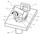
도 1a는 일부 실시예들에 따른 에어백 모듈 및 에어백 모듈을 스티어링 휠에 결합하기 위한 장착 인터페이스의 분해도이다.
도 1b는 장착 인터페이스에 결합된 장착 스프링 클립들을 갖는 도 1a의 에어백 모듈 및 장착 인터페이스를 도시한다.
도 2는 도 1a 및 도 1b의 에어백 모듈 및 장착 인터페이스의 평면도이다.
도 3a는 장착 인터페이스의 장착 구조물들과 스프링 클립 사이의 접촉 인터페이스들을 볼 수 있게 하기 위해 가상선으로 도시된 장착 인터페이스의 다양한 요소들을 갖는 장착 인터페이스 및 스프링 클립의 확대도이다.
도 3b는 스프링 클립과 후크형 프롱 사이의 맞물림 후의 장착 인터페이스 및 스프링 클립을 도시한다.
도 4a 및 도 4b는 스티어링 휠 또는 다른 차량 구조를 갖는 에어백 모듈의 분해를 허용하기 위해 스프링 클립을 후크형 프롱으로부터 해체하는 데 사용되는 툴을 도시한다.
도 5a 및 도 5b는 스프링 클립을 장착 인터페이스에 결합시키기 위한 방법의 단계들을 도시한다.
도 6a 내지 도 6c는 장착 인터페이스 내에 안착된 스프링 클립에 후크형 프롱을 결합하기 위한 방법의 단계들을 도시한다.BRIEF DESCRIPTION OF THE DRAWINGS Non-limiting and non-exhaustive embodiments of the present invention, including various embodiments thereof, are described with reference to the drawings.
1A is an exploded view of an airbag module and a mounting interface for coupling the airbag module to a steering wheel in accordance with some embodiments.
1B shows the airbag module and mounting interface of FIG. 1A with mounting spring clips coupled to the mounting interface;
FIG. 2 is a plan view of the airbag module and mounting interface of FIGS. 1A and 1B ;
3A is an enlarged view of the spring clip and the mounting interface with the various elements of the mounting interface shown in phantom to allow viewing of contact interfaces between the mounting structures of the mounting interface and the spring clip;
3B shows the spring clip and the mounting interface after engagement between the spring clip and the hooked prong.
4A and 4B show the tools used to disengage the spring clips from the hooked prongs to allow disassembly of the airbag module having a steering wheel or other vehicle structure.
5a and 5b show the steps of a method for coupling a spring clip to a mounting interface.
6A-6C show the steps of a method for engaging a hooked prong to a spring clip seated within a mounting interface.
본 발명의 다양한 실시예들과 일치하는 장치, 시스템들, 및 방법들의 상세한 설명이 하기에 제공된다. 몇몇 실시예들이 기술되지만, 본 발명이 개시된 특정 실시예들 중 임의의 것으로 제한되지 않고, 대신에 다수의 대안예들, 변형들, 및 등가물들을 포함한다는 것이 이해되어야 한다. 또한, 많은 구체적인 상세사항들이 본 명세서에 개시된 실시예들의 완전한 이해를 제공하기 위해 하기의 설명에서 설명되지만, 일부 실시예들은 이들 상세사항들 중 일부 또는 전부가 없이도 실시될 수 있다. 더욱이, 명확함을 위해, 본 기술 분야에 공지된 소정의 기술적 자료는 본 발명을 불필요하게 불명료하게 하는 것을 피하기 위해 상세히 기술되지 않았다.A detailed description of apparatus, systems, and methods consistent with various embodiments of the present invention is provided below. While several embodiments have been described, it should be understood that the invention is not limited to any of the specific embodiments disclosed, but instead covers many alternatives, modifications, and equivalents. In addition, although many specific details are set forth in the following description in order to provide a thorough understanding of the embodiments disclosed herein, some embodiments may be practiced without some or all of these details. Moreover, for the sake of clarity, certain technical material known in the art has not been described in detail in order to avoid unnecessarily obscuring the present invention.
본 명세서에 사용되는 바와 같이, 용어 "실질적으로" 는 지시된 바와 같은 기능을 하는 작용, 특성, 속성, 상태, 구조, 항목, 또는 결과의 완전하거나 거의 완전한 범위 또는 정도를 지칭한다. 예를 들어, "실질적으로" 원통형 또는 "실질적으로" 수직인 물체는 물체/특징부가 동일하거나 거의 동일한 기능을 생성하도록 원통형/수직이거나 거의 원통형/수직인 것을 의미할 것이다. 이러한 용어에 의해 제공되는 정확한 허용 편차 정도는 특정 상황에 좌우될 수 있다. "실질적으로"의 사용은 작용, 특성, 속성, 상태, 구조, 항목, 또는 결과의 완전한 또는 거의 완전한 결여를 지칭하기 위해 반대의 의미에서 사용될 때에도 동등하게 적용가능하다. 예를 들어, 저부가 "실질적으로 없는" 구조는 저부가 완전히 결여되거나, 또는 저부가 거의 완전히 결여될 것이어서 그 효과가 마치 저부가 완전히 결여된 것과 사실상 동일할 것이다.As used herein, the term “substantially” refers to the complete or near-complete extent or extent of an action, characteristic, attribute, state, structure, item, or result that functions as indicated. For example, a “substantially” cylindrical or “substantially” vertical object would mean that the object/feature is cylindrical/vertical or nearly cylindrical/vertical such that the object/feature produces the same or nearly identical function. The exact degree of tolerance provided by these terms may depend on the particular situation. The use of “substantially” is equally applicable when used in the opposite sense to refer to the complete or near complete absence of an action, characteristic, attribute, state, structure, item, or result. For example, a structure that is “substantially devoid of” a bottom would be completely devoid of a bottom, or would almost completely lack a bottom, so that the effect would be substantially the same as if it were completely devoid of a bottom.
유사하게, 본 명세서에 사용되는 바와 같이, 용어 "약"은 주어진 값이 범위와 연관된 기능을 여전히 달성하면서 종점의 "약간 위" 또는 "약간 아래"가 될 수 있도록 수치 범위 종점에 유연성을 제공하는 데 사용된다.Similarly, as used herein, the term “about” provides flexibility to the endpoint of a numerical range such that a given value can be “slightly above” or “slightly below” the endpoint while still achieving the function associated with the range. used to
본 발명의 실시예들은 도면을 참조함으로써 가장 잘 이해될 수 있으며, 여기서 유사한 부분들은 동일한 도면 부호들로 지시될 수 있다. 본 명세서의 도면에 전반적으로 기술되고 예시된 바와 같은 개시된 실시예들의 구성요소들이 매우 다양한 상이한 구성들로 배열 및 설계될 수 있다는 것이 쉽게 이해될 것이다. 따라서, 본 발명의 장치 및 방법들의 실시예들의 하기의 상세한 설명은 청구된 바와 같은 본 발명의 범주를 제한하고자 하는 것이 아니라, 단지 본 발명의 가능한 실시예들을 대표하는 것이다. 또한, 방법의 단계들은, 달리 명시되지 않는 한, 반드시 임의의 특정 순서로, 또는 심지어 순차적으로 실행될 필요는 없으며, 단계들이 단지 한 번만 실행될 필요도 없다. 이제, 소정의 바람직한 실시예들 및 구현예들에 관한 추가의 상세 사항이 첨부 도면을 참조하여 보다 상세히 기술될 것이다.BRIEF DESCRIPTION OF THE DRAWINGS Embodiments of the present invention may be best understood by reference to the drawings, wherein like parts may be designated by like reference numerals. It will be readily understood that components of the disclosed embodiments as generally described and illustrated in the drawings herein may be arranged and designed in a wide variety of different configurations. Accordingly, the following detailed description of embodiments of apparatus and methods of the present invention is not intended to limit the scope of the invention as claimed, but is merely representative of possible embodiments of the invention. Furthermore, the steps of a method need not necessarily be executed in any particular order, or even sequentially, unless otherwise specified, and the steps need not be executed only once. Further details relating to certain preferred embodiments and implementations will now be described in more detail with reference to the accompanying drawings.
도 1a 및 도 1b는 일부 실시예들에 따라 스티어링 휠(104)에 결합되도록 구성된 에어백 모듈(102)을 포함하는 조립체(100)를 도시한다. 결합 조립체는 팽창기(105)를 포함하는 에어백 모듈(102)을, 이 도면들에 도시된 장착 인터페이스들(110A, 110B)과 같은 하나 이상의 장착 인터페이스들을 포함할 수 있는 스티어링 휠(104)에 장착하는 것 또는 달리 결합하는 것을 용이하게 하기 위해 제공될 수 있다. 이러한 장착 인터페이스들은 전형적으로 에어백 모듈(102) 및 스티어링 휠(104) 상의 다른 요소들 둘 모두로부터의 특정 요소들을 포함할 것임을 이해해야 한다. 그러나, 당업자가 이해할 바와 같이, 도시된 요소들은 원하는 대로 대안적인 장소들에 위치될 수 있다. 예를 들어, 도 1a 및 도 1b의 분해도들에 대부분의 요소들이 에어백 모듈(102)의 일부인 것으로 도시되어 있지만, 에어백 모듈(102)에 도시된 하나 이상의 요소들이 대신에 스티어링 휠(104) 상에 위치될 수 있고, 그 반대도 마찬가지이다. 일부 실시예들에서, 예를 들어, 아래에서 더 상세히 도시되고 논의된 하나 이상의 장착 요소들은 예를 들어, 혼 플레이트 또는 스티어링 휠(104)의 다른 부분에 오버몰딩될 수 있다.1A and 1B show an
도 1 및 도 2에 도시된 실시예는 각각이 에어백 모듈(102)을 스티어링 휠(104)에 로킹하기 위해 하나의 장착 인터페이스(110)에 결합하도록 구성된 복수의 스프링 클립들(150)을 더 포함한다. 그러나, 임의의 수의 이러한 장착 인터페이스들(110)이 사용될 수 있음을 또한 이해해야 한다. 예를 들어, 일부 실시예들에서, 단일, 바람직하게는 중앙집중식 장착 인터페이스(110)가 에어백 모듈(102)을 제자리에 고정하기에 충분할 수 있다. 다른 실시예들에서, 4 개의 이러한 장착 인터페이스들(110)이 사용될 수 있거나, 또는 원하는 대로 임의의 다른 수가 사용될 수 있다. 도 1a는 그들 개개의 장착 인터페이스들(110)로부터 분리된 스프링 클립들(150)을 도시하고, 도 1b는 이들이 제자리에 고정된 것을 도시한다. 그러나, 통상적으로, 스프링 클립들(150)이 결합된 핀들, 프롱들 또는 다른 결합 부재들이 에어백 모듈(102) 또는 스티어링 휠(104)로부터 연장될 것이고, 따라서, 이하의 보다 상세한 논의로부터 명백해지는 바와 같이, 설명의 편이를 위해 도 1 및 도 2에 도시된 프롱들이 이 도면들에서 분리된 것으로 도시되어 있고/있거나, 인터페이스 자체가 이 도면들에서 분리된 것으로 도시되어 있는 것으로 이해되어야 한다.The embodiment shown in FIGS. 1 and 2 further includes a plurality of spring clips 150 each configured to couple to one mounting
도 3a 및 도 3b는 스프링 클립(150)이 내부에 위치된 장착 인터페이스(110)의 확대도를 도시한다. 이 도면들에 도시된 바와 같이, 스프링 클립(150)은, 일부 실시예들에서, 개방 중심 영역 주위로 연장되는 4 개의 레그들 또는 측부들을 포함할 수 있다. 아래에서 더 논의되는 바와 같이, 결합 프롱(160) 또는 다른 돌출 결합 부재가 스프링 클립(150)을 제자리에 로킹하기 위해 조립 동안 이 중심 영역 내에 삽입될 수 있다.3A and 3B show enlarged views of the mounting
스프링 클립(150)은 제2 레그/측부(154)에 대향하여 연장되는 제1 레그/측부(152)를 포함한다. 도시된 실시예에서, 이러한 레그들/측부들 각각은 대응하는 대향하는 레그/측부에 평행하게 연장되고 이어서, 일부 실시예들에서 약 20 내지 약 40도 사이일 수 있는, 예각 β로 서로를 향해 각을 이루고 있는 제1 부분을 포함한다. 보다 바람직한 실시예들에서, 각 β는 약 20도 내지 약 40도 사이일 수 있다. 또한, 도시된 실시예를 포함하는 바람직한 실시예들에서, 대향하는 레그들(152/154)은 스프링 클립(150)의 중심 축 및 장착 인터페이스(110)의 중심 축 둘 모두에 대해 대칭적이라는 것을 알 수 있다. 또한, 스프링 클립(150)은 바람직하게는 다양한 측부들 각각이 동일한 평면에서 서로 평행하게 연장되지만, 본 명세서에 설명되고 첨부 도면들에 도시된 바와 같이, 이 평면 내에서 서로를 향해 각을 이룰 수 있도록 형성된다는 것을 알 수 있다.The
대향하는 측부들/레그들(152, 154)은 측부들/레그들(152 및/또는 154)에 수직 또는 적어도 실질적으로 수직으로 연장될 수 있는 제3 측부/레그(156)를 따라 연결된다. 측부/레그(156)에 대향하는 부분 측부/레그(158)가 제공될 수 있으며, 이는 아래에서 논의되는 바와 같이, 스프링 클립(150)을 해제하여 차량의 스티어링 휠 또는 다른 장착 표면/요소로부터 에어백 모듈을 해제하는 데 사용될 수 있는 툴을 갖는 인터페이스를 위해 제공할 수 있다. 따라서, 도시된 실시예에서, 스프링(150)은 사다리꼴 형상을 정의한다. 또한, 툴 인터페이스 영역은 프롱(160)이 연장되어 스프링 클립(150)을 제자리에 로킹하는 전술한 개방/중심 영역의 외부에 있다.Opposing sides/
장착 인터페이스(110)는 개구(111), 및 스프링(150)을 가이드하고/하거나 스프링(150)을 제자리에 로킹하기 위한 하나 이상의 주변 가이드/장착 특징부들을 포함한다. 특히, 도 3b에 도시된 바와 같이, 제1 장착 구조물(112)이 인터페이스(110)의 일 측부 상에 제공되고, 제2 장착 구조물(114)이 대향 측부 상에 제공된다. 따라서, 장착 구조물(112)은 스프링(150)의 각진 레그(154)와 맞물리도록 구성되고, 유사하게, 장착 구조물(114)은 스프링(150)의 레그(152)의 각진 부분과 맞물리도록 구성된다. 이러한 장착 구조물들(112/114) 중 하나 또는 둘 모두는 조립 및/또는 분해 동안 스프링(150)의 원하는 휨/움직임을 용이하게 하기 위해 다양한 특징부들/표면들을 포함할 수 있다. 예를 들어, 아래에서 더 상세히 논의되는 바와 같이, 설치 중에, 스프링(150)의 측부들 중 하나의 각진 표면과 맞물려 그 측부의 회전을 방지할 수 있는 각진 표면이 제공될 수 있는 반면, 대향 측부는 포인트 접촉을 가져 스프링(150)의 한 측부만의 회전을 용이하게 한다. 유사하게, 장착 구조물들(112/114) 중 하나 또는 둘 모두는, 스프링(150)을 제자리에 고정시키고 의도하지 않은 분해를 방지하기 위해, 스프링(150)이 오버행 위로 휘어 그 아래에 정의된 리세스 내에 안착될 수 있게 하는 하부 리세스 영역을 정의하는 오버행을 포함할 수 있다.The mounting
원하는 경우 다른 가이드 특징부들이 또한 제공될 수 있다. 예를 들어, 도시된 실시예에서, 가이드/장착 구조물들(116, 118)은 개구(111)의 대향 측부들 상에 서로 대향하여 제공된다. 구조물들(116)은 본 개시내용 전반에 걸쳐 논의된 바와 같이, 스프링(150)을 제자리에 유지하고, 설치/조립의 다양한 단계들 동안 이를 앞뒤로 가이드할 수 있다. 도 3b에 도시된 바와 같이, 스프링(150)이 전술한 가이드/장착 구조물들 중 하나 이상을 사용하여 제자리에 있으면, 에어백 모듈(102) 또는 스티어링 휠(104)로부터 연장되고 그의 부분일 수 있는 결합 프롱(160)이, 에어백 모듈(102)을 스티어링 휠(104)에 고정하거나, 다른 실시예들에서, 에어백 모듈을 차량 내의 다른 적합한 위치에 고정하기 위해, 개구(111)를 통해 연장될 수 있다. 또한, 원하는 경우, 인접 구조물(119)이 제공될 수 있으며, 이는 에어백 모듈(102)을 설치해제하기 위한 툴을 가이드하는 데 사용될 수 있고/있거나, 이를테면 프롱(160)의 존재의 부재시 스프링(150)이 너무 멀리 병진하는 것을 방지하기 위해, 스프링(150)을 구속하는 데 사용될 수 있다. 도 5a 및 도 5b에 도시된 바와 같이, 구조물(119)은, 일부 실시예들에서, 툴이 관통하여 연장될 수 있게 하는 중앙 개구를 포함할 수 있다. 개구를 정의하는 벽들은, 사용 중에 스프링(150)을 맞물리게 하는 데 사용될 수 있으며, 다시, 설치 중에 스프링(150)의 과도한 병진을 방지하기 위해 사용될 수 있다.Other guide features may also be provided if desired. For example, in the illustrated embodiment, guide/mounting
도 4a 및 도 4b는 스티어링 휠(104)로부터 에어백 모듈(102)을 설치해제하기 위한 가능한 단계들을 도시한다. 특히, 툴(50)은 레그(158)와 접촉하고, 프롱(160)이 제거될 수 있게 하기 위해 스프링(150)이 프롱(160)으로부터 멀리 병진할 수 있도록 힘을 (도 4a의 화살표로 표시된 바와 같이 이 도면들의 관점에서 아래쪽으로) 인가하는 데 사용될 수 있다.4A and 4B show possible steps for uninstalling the
도 5a 및 도 5b는 스프링(150)을 인터페이스(110)에 결합하는 것과 관련된 단계들을 도시한다. 도 5a에 도시된 바와 같이, 스프링(150)은 초기에 인터페이스(110)의 일 측면, 즉 장착 구조물(112) 주위에 위치될 수 있다. 그런 다음, 스프링(150)은, 도 5a의 화살표로 표시된 바와 같이, 장착 구조물(112)에 접촉하는 레그에 대향하는 레그가 대향 장착 구조물(114) 주위로 회전하도록, 회전될 수 있다. 도 5a에서 점선으로 표시된 바와 같이, 바람직하게는, 제1 측부에 대향하는 스프링(150)의 제2 측부가 회전함에 따라 스프링(150)의 제1 측부의 회전을 방지하기 위한 피봇팅 표면을 제공하도록, 이 측부 상의 스프링(150)과 장착 구조물(112) 사이에 선형 접촉이 유지된다. 따라서, 스프링(150)을 인터페이스(110)에 결합하는 것은 병진 이동 및 회전 이동 둘 모두를 수반한다. 선택적으로, 이러한 결합 절차를 용이하게 하기 위해 툴(55)이 사용될 수 있다.5A and 5B show the steps involved in coupling the
스프링 클립(150)이 인터페이스(110)의 다양한 장착/가이드 구조물들에 의해 적절히 구속되어 제자리에 있으면, 예를 들어, 에어백 모듈(102)을 스티어링 휠(104)에 장착하는 것을 고정하기 위해 프롱들(160)이 개구들(111)을 통해 연장될 수 있다. 이 단계들은 도 6a 내지 도 6c에 도시되어 있다. 본원의 다른 곳에서 설명된 바와 같이, 인터페이스(110)는 스프링 클립(150)을 제자리에 로킹하도록, 그리고 도 6a 내지 도 6c에 도시된 바와 같이, 핀/프롱(160)을 수용하여 두 구조물들을 제자리에, 이를테면 에어백 모듈을 스티어링 휠에, 로킹하기 위해 스프링 클립(150)의 병진만을 허용하도록 구성된다는 것이 이해되어야 한다.When the
도 6a는 스프링 클립(150)이 구조물들(112 내지 118) 주위에 위치되고 구속되는 이 프로세스의 초기 단계를 도시한다. 또한, 이 도면에 도시된 바와 같이, 스프링 클립(150)은 개구(111) 위로 부분적으로 연장되며, 이는 프롱(160)이, 그를 통해 진입하는 동안, 프롱(160)을 수용하도록 스프링 클립(150)을 자동으로 재위치시킬 수 있게 하고, 이어서, 아래에서 논의되는 바와 같이, 그 내부에 프롱(160)을 로킹하기 위해 자동으로 제 위치로 다시 슬라이딩할 수 있게 한다.6A shows an initial step in this process in which a
도 6c에서 가장 잘 볼 수 있는 바와 같이, 일부 실시예들에서, 조립 동안 프롱(160)은 스프링 클립(150)을 병진시키도록 구성된 램프형 팁(162)을 포함할 수 있다. 유사하게, 프롱(160)은 램프형 팁(162)에 인접한 오목부 및/또는 후크부(164)를 더 포함할 수 있다. 후크부(164)는 스프링 클립(150)이 그 초기 구성을 향해 다시 병진하고 제자리에 로킹될 수 있게 하기 위해 조립 동안 램프형 팁(162)이 스프링 클립(150)을 지나 연장된 후에 스프링 클립(150)의 일부를 수용하도록 구성될 수 있다.As best seen in FIG. 6C , in some embodiments, the
특히, 도 6b는 프롱(160)이 개구(111)를 통해 전진됨에 따른, 스프링 클립(150)과 프롱(160)의 램프형 팁(162)의 전술한 맞물림을 도시한다. 개구(111) 및 프롱(160)의 램프형 팁(162)과 스프링 클립(150)의 중첩으로 인해, 이를 통한 프롱(160)의 전진은 도 6b에 도시된 바와 같이 장착 인터페이스(110) 바닥을 향해 스프링 클립(150)이 병진되게 한다. 스프링 클립(150)이 프롱(160)의 인접한 오목부/후크부(164) 내에 안착할 수 있는 지점까지 프롱(160)이 전진했으면, 스프링 클립(150)은 이어서 프롱(160)이 스프링 클립(150)을 제자리에 로킹할 수 있게 하기 위해 대향 방향으로 다시 병진한다. 스프링 클립(150)의 각진 부분들 및 인터페이스(110)의 다양한 가이드/장착 요소들과 이들의 맞물림으로 인해, 스프링 클립(150)의 하향 방향으로의 병진은 대향 방향으로 힘/바이어스를 초래하여, 스프링 클립(150)이 램프형 팁(162)의 표면을 지나 전진하자마자, 대향 방향으로의 이러한 병진/움직임이 자동으로 발생하고, 프롱(160)이 제자리에 로킹되고, 이에 의해 에어백 모듈(102)을 스티어링 휠(104)에 대해 제자리에 로킹하는 도 6c에 도시된 최종 구성이 된다. 물론, 하나의 스프링 클립(150), 하나의 프롱(160), 및 하나의 대응하는 장착 인터페이스(110)가 도 6a 내지 도 6c에 도시되어 있지만, 이러한 결합/장착을 제공하기 위해 각각 동시에 결합될 수 있는 다수의 유사하거나 동일한 스프링 클립들, 프롱들 및 장착 인터페이스들이 제공될 수 있다는 것을 이해해야 한다.In particular, FIG. 6B shows the aforementioned engagement of the ramped
전술한 명세서는 다양한 실시예들 및 구현예들을 참조하여 설명하였다. 그러나, 당업자는 본 발명의 범주로부터 벗어남이 없이 다양한 변형들 및 변경들이 이루어질 수 있음을 이해할 것이다. 예를 들어, 다양한 동작 단계들뿐만 아니라 동작 단계들을 수행하기 위한 컴포넌트들은 특정 응용에 따라 또는 시스템의 동작과 연관된 임의의 수의 비용 기능들을 고려하여 다양한 방식들로 구현될 수 있다. 따라서, 단계들 중 임의의 하나 이상이 삭제, 변형, 또는 다른 단계들과 조합될 수 있다. 또한, 본 발명은 제한적인 의미보다는 예시적인 의미로 간주되어야 하며, 모든 그러한 변형들은 그의 범주 내에 포함되는 것으로 의도된다. 마찬가지로, 이득들, 다른 이점들, 및 문제들에 대한 해결책들이 다양한 실시예들에 관하여 전술되었다. 그러나, 이득들, 이점들, 문제들에 대한 해결책들, 및 임의의 이득, 이점, 또는 해결책을 발생시키거나 더 명확해지게 할 수 있는 임의의 요소(들)는 중요하거나, 요구되거나, 필수적인 특징부 또는 요소로서 해석되어서는 안 된다.The foregoing specification has been described with reference to various embodiments and implementations. However, it will be understood by those skilled in the art that various modifications and changes may be made without departing from the scope of the present invention. For example, the various operational steps as well as the components for performing the operational steps may be implemented in various ways, depending on a particular application or taking into account any number of cost functions associated with operation of the system. Accordingly, any one or more of the steps may be deleted, modified, or combined with other steps. Furthermore, the present invention is to be regarded in an illustrative rather than a restrictive sense, and all such modifications are intended to be included within their scope. Likewise, benefits, other advantages, and solutions to problems have been described above with respect to various embodiments. However, the benefits, advantages, solutions to problems, and any element(s) that may give rise to or further clarify any benefit, advantage, or solution are important, required, or essential features. It should not be construed as a part or element.
당업자는 본 발명의 기본 원리들로부터 벗어남이 없이 전술된 실시예들의 상세 사항에 대해 많은 변경들이 이루어질 수 있음을 이해할 것이다. 따라서, 본 발명의 범주는 단지 하기의 청구범위에 의해서만 결정되어야 한다.Those skilled in the art will appreciate that many changes can be made to the details of the above-described embodiments without departing from the basic principles of the invention. Accordingly, the scope of the present invention should be determined solely by the following claims.
Claims (7)
에어백 모듈(102); 및
상기 에어백 모듈(102)을 차량 구조물에 결합하기 위한 장착 인터페이스(110)를 포함하고, 상기 장착 인터페이스(110)는,
대향하는 장착 표면들;
상기 장착 인터페이스(110)와 맞물리도록 구성된 스프링(150) - 상기 스프링(150)은 적어도 3 개의 측부들(152, 154, 156)을 포함하는 주연부를 정의함 -; 및
상기 에어백 모듈(102)을 상기 장착 인터페이스(110)에 고정하기 위해 상기 스프링(150)에 맞물리도록 구성된 결합 프롱(160) - 상기 결합 프롱(160)은 상기 적어도 3 개의 측부들(152, 154, 156) 중 하나에 맞물리도록 구성되고 상기 에어백 모듈(102)을 상기 장착 인터페이스(110)에 고정하는 동안 상기 스프링(150)을 제1 방향으로 병진시키도록 구성됨 - 을 포함하는 것을 특징으로 하는, 에어백 조립체.An airbag assembly comprising:
airbag module 102 ; and
a mounting interface (110) for coupling the airbag module (102) to a vehicle structure, the mounting interface (110) comprising:
opposing mounting surfaces;
a spring (150) configured to engage the mounting interface (110), the spring (150) defining a perimeter comprising at least three sides (152, 154, 156); and
a coupling prong 160 configured to engage the spring 150 to secure the airbag module 102 to the mounting interface 110 - the coupling prong 160 comprising the at least three sides 152, 154; 156) and configured to translate the spring (150) in a first direction while securing the airbag module (102) to the mounting interface (110). assembly.
Applications Claiming Priority (3)
| Application Number | Priority Date | Filing Date | Title |
|---|---|---|---|
| US16/709,104 US11383665B2 (en) | 2019-12-10 | 2019-12-10 | Driver airbag module coupling assemblies |
| US16/709,104 | 2019-12-10 | ||
| PCT/US2020/063850 WO2021119038A1 (en) | 2019-12-10 | 2020-12-08 | Driver airbag module coupling assemblies |
Publications (1)
| Publication Number | Publication Date |
|---|---|
| KR20220108151A true KR20220108151A (en) | 2022-08-02 |
Family
ID=73943377
Family Applications (1)
| Application Number | Title | Priority Date | Filing Date |
|---|---|---|---|
| KR1020227022983A Pending KR20220108151A (en) | 2019-12-10 | 2020-12-08 | Driver Airbag Module Combination Assembly |
Country Status (5)
| Country | Link |
|---|---|
| US (1) | US11383665B2 (en) |
| EP (1) | EP4072905B1 (en) |
| KR (1) | KR20220108151A (en) |
| CN (1) | CN114641413B (en) |
| WO (1) | WO2021119038A1 (en) |
Families Citing this family (2)
| Publication number | Priority date | Publication date | Assignee | Title |
|---|---|---|---|---|
| FR3098166B1 (en) * | 2019-07-04 | 2024-10-25 | Autoliv Dev | Removable mounting device for an airbag module on a steering wheel |
| WO2024171688A1 (en) * | 2023-02-15 | 2024-08-22 | オートリブ ディベロップメント エービー | Vehicle steering wheel device |
Family Cites Families (30)
| Publication number | Priority date | Publication date | Assignee | Title |
|---|---|---|---|---|
| US5380037A (en) * | 1993-10-25 | 1995-01-10 | General Motors Corporation | Snap-in inflatable restraint module mounting mechanism including latch elements |
| FR2790044B1 (en) * | 1999-02-19 | 2001-05-25 | Gersteen Iso Delta | VEHICLE STEERING WHEEL ELEMENT AND STEERING WHEEL COMPRISING THIS ELEMENT |
| DE10030471C1 (en) * | 2000-06-21 | 2001-07-26 | Bosch Gmbh Robert | Automobile airbag module has mechanical locking device and electrical contact device for connecting gas generator detonation device to control device |
| EP1167132B1 (en) * | 2000-06-27 | 2004-06-09 | Toyoda Gosei Co., Ltd. | Air bag module mounting structure |
| FR2812606B1 (en) | 2000-08-02 | 2002-10-31 | Autoliv Isodelta | VEHICLE STEERING WHEEL ELEMENT WITH LOCKING SYSTEM, AND STEERING WHEEL COMPRISING SAME |
| DE20017527U1 (en) * | 2000-10-12 | 2001-02-22 | TRW Automotive Safety Systems GmbH & Co. KG, 63743 Aschaffenburg | Vehicle steering wheel |
| US7185915B2 (en) * | 2003-02-27 | 2007-03-06 | Toyoda Gosei Co., Ltd. | Steering wheel incorporating air bag device |
| US7059631B2 (en) | 2003-04-29 | 2006-06-13 | Toyoda Gosei Co., Ltd. | Method and apparatus for coupling a driver's side airbag to a steering wheel |
| DE20307142U1 (en) * | 2003-05-07 | 2003-09-18 | TRW Automotive Safety Systems GmbH, 63743 Aschaffenburg | module |
| US7533897B1 (en) * | 2005-02-16 | 2009-05-19 | Key Safety Systems, Inc. | Method and apparatus for securing an air bag |
| JP4797584B2 (en) | 2005-03-16 | 2011-10-19 | タカタ株式会社 | Steering wheel with airbag device |
| ATE388862T1 (en) | 2005-03-21 | 2008-03-15 | Delphi Tech Inc | STEERING WHEEL ARRANGEMENT |
| GB2433234A (en) * | 2005-12-08 | 2007-06-20 | Autoliv Dev | A mounting arrangement for an airbag |
| JP4758390B2 (en) * | 2007-05-09 | 2011-08-24 | トヨタ自動車株式会社 | Knee airbag device with column and its assembly method |
| JP5153526B2 (en) * | 2008-02-01 | 2013-02-27 | 本田技研工業株式会社 | Steering wheel vibration reduction structure |
| DE102008013526B4 (en) * | 2008-03-07 | 2012-02-02 | Autoliv Development Ab | Safety arrangement and method for producing a safety arrangement |
| JP5497485B2 (en) * | 2010-03-04 | 2014-05-21 | 芦森工業株式会社 | Airbag device |
| JP5206756B2 (en) * | 2010-09-30 | 2013-06-12 | 豊田合成株式会社 | Steering wheel with airbag device |
| US9027960B1 (en) * | 2011-11-30 | 2015-05-12 | Autoliv Development Ab | Front airbag device |
| JP5826658B2 (en) * | 2012-02-07 | 2015-12-02 | タカタ株式会社 | Air bag device and horn switch device |
| DE102014001821A1 (en) * | 2014-02-13 | 2015-08-13 | Dalphi Metal Espana, S.A. | Device for positioning an airbag module in a motor vehicle |
| EP2910425B1 (en) * | 2014-02-20 | 2020-08-05 | Dalphi Metal España, S.A. | Horn circuit |
| EP3178707B1 (en) * | 2015-12-08 | 2018-07-18 | Autoliv Development AB | Steering wheel |
| US11034319B2 (en) * | 2016-06-10 | 2021-06-15 | Key Safety Systems, Inc. | Air bag module |
| JP2017222281A (en) * | 2016-06-16 | 2017-12-21 | 豊田合成株式会社 | Attachment structure of airbag device for driver seat |
| US11034374B2 (en) * | 2017-08-10 | 2021-06-15 | Toyoda Gosei Co., Ltd. | Steering wheel |
| DE102017119886A1 (en) * | 2017-08-30 | 2019-02-28 | Trw Automotive Safety Systems Gmbh | SPRING ELEMENT FOR FASTENING A GASSACK MODULE TO A VEHICLE WHEEL AND A STEERING WHEEL ASSEMBLY WITH SUCH A SPRING ELEMENT |
| DE102018102755A1 (en) * | 2018-02-07 | 2019-08-08 | Autoliv Development Ab | Airbag module, method for producing a gas bag module and steering wheel |
| US10926698B2 (en) * | 2018-12-17 | 2021-02-23 | Key Safety Systems, Inc. | Integrated steering wheel, vibration absorber, and driver airbag |
| US11518334B2 (en) * | 2019-06-24 | 2022-12-06 | Joyson Safety Systems Acquisition Llc | Methods and systems for pre-fixing an airbag module during installation |
-
2019
- 2019-12-10 US US16/709,104 patent/US11383665B2/en active Active
-
2020
- 2020-12-08 CN CN202080077218.0A patent/CN114641413B/en active Active
- 2020-12-08 KR KR1020227022983A patent/KR20220108151A/en active Pending
- 2020-12-08 EP EP20828926.4A patent/EP4072905B1/en active Active
- 2020-12-08 WO PCT/US2020/063850 patent/WO2021119038A1/en unknown
Also Published As
| Publication number | Publication date |
|---|---|
| US20210170979A1 (en) | 2021-06-10 |
| CN114641413A (en) | 2022-06-17 |
| EP4072905B1 (en) | 2023-10-04 |
| US11383665B2 (en) | 2022-07-12 |
| EP4072905A1 (en) | 2022-10-19 |
| CN114641413B (en) | 2023-11-10 |
| WO2021119038A1 (en) | 2021-06-17 |
Similar Documents
| Publication | Publication Date | Title |
|---|---|---|
| JP5027919B2 (en) | clip | |
| US9718410B2 (en) | Assembly for connecting a roof rack to a vehicle | |
| US20090263210A1 (en) | Connecting assembly for fastening an add-on element on a carrier element | |
| KR20220108151A (en) | Driver Airbag Module Combination Assembly | |
| JP7455552B2 (en) | An airbag module, a method for installing the airbag module, and a steering assembly including the airbag module. | |
| KR20100001539U (en) | Fastener clip and manufacturing method of fastener clip | |
| US9776578B2 (en) | Clip and pillar garnish fixing structure | |
| US11591000B2 (en) | Steering apparatus assembly for a motor vehicle | |
| JP2014527140A (en) | An assembly comprising at least two components fixed together | |
| KR20190094220A (en) | Fastener assembly | |
| US20150015048A1 (en) | Folding mechanism for a head restraint | |
| JP2009089587A (en) | Grommet | |
| US10001211B2 (en) | Shift knob assembly for vehicle | |
| JP6438050B2 (en) | Holding device and pins for placement on such a holding device | |
| JP6060228B2 (en) | Vehicle holding parts | |
| JP6535422B2 (en) | Mounting structure for internal parts of fuel tank | |
| JP5878321B2 (en) | Leg cover and vehicle seat provided with the leg cover | |
| JP2005289349A (en) | Air bag module provided with adjustable cover | |
| JP5199547B2 (en) | Wire harness connection structure | |
| JP2011036030A (en) | Clip and wire harness with clip | |
| JP4253402B2 (en) | clip | |
| US6817882B1 (en) | Device for locking a plug in the plug-in position thereof in a vibration resistant manner | |
| KR101948134B1 (en) | A clip assembly facilitates the replacement of the bolt | |
| JP6581820B2 (en) | Electrical junction box, junction box body and protective member | |
| CN103661675B (en) | Reversible locking connection for improved assembly and disassembly of components at body-in-white parts |
Legal Events
| Date | Code | Title | Description |
|---|---|---|---|
| PA0105 | International application |
Patent event date: 20220705 Patent event code: PA01051R01D Comment text: International Patent Application |
|
| PA0201 | Request for examination | ||
| PG1501 | Laying open of application | ||
| E902 | Notification of reason for refusal | ||
| PE0902 | Notice of grounds for rejection |
Comment text: Notification of reason for refusal Patent event date: 20240219 Patent event code: PE09021S01D |
|
| E90F | Notification of reason for final refusal | ||
| PE0902 | Notice of grounds for rejection |
Comment text: Final Notice of Reason for Refusal Patent event date: 20241010 Patent event code: PE09021S02D |