KR20220038691A - High-Resolution Solid-State LIDAR Transmitter - Google Patents
High-Resolution Solid-State LIDAR Transmitter Download PDFInfo
- Publication number
- KR20220038691A KR20220038691A KR1020227003018A KR20227003018A KR20220038691A KR 20220038691 A KR20220038691 A KR 20220038691A KR 1020227003018 A KR1020227003018 A KR 1020227003018A KR 20227003018 A KR20227003018 A KR 20227003018A KR 20220038691 A KR20220038691 A KR 20220038691A
- Authority
- KR
- South Korea
- Prior art keywords
- sub
- pixel
- aperture
- laser
- microlens
- Prior art date
- Legal status (The legal status is an assumption and is not a legal conclusion. Google has not performed a legal analysis and makes no representation as to the accuracy of the status listed.)
- Pending
Links
Images


Classifications
-
- G—PHYSICS
- G01—MEASURING; TESTING
- G01S—RADIO DIRECTION-FINDING; RADIO NAVIGATION; DETERMINING DISTANCE OR VELOCITY BY USE OF RADIO WAVES; LOCATING OR PRESENCE-DETECTING BY USE OF THE REFLECTION OR RERADIATION OF RADIO WAVES; ANALOGOUS ARRANGEMENTS USING OTHER WAVES
- G01S17/00—Systems using the reflection or reradiation of electromagnetic waves other than radio waves, e.g. lidar systems
- G01S17/88—Lidar systems specially adapted for specific applications
- G01S17/93—Lidar systems specially adapted for specific applications for anti-collision purposes
- G01S17/931—Lidar systems specially adapted for specific applications for anti-collision purposes of land vehicles
-
- G—PHYSICS
- G01—MEASURING; TESTING
- G01S—RADIO DIRECTION-FINDING; RADIO NAVIGATION; DETERMINING DISTANCE OR VELOCITY BY USE OF RADIO WAVES; LOCATING OR PRESENCE-DETECTING BY USE OF THE REFLECTION OR RERADIATION OF RADIO WAVES; ANALOGOUS ARRANGEMENTS USING OTHER WAVES
- G01S17/00—Systems using the reflection or reradiation of electromagnetic waves other than radio waves, e.g. lidar systems
- G01S17/88—Lidar systems specially adapted for specific applications
- G01S17/89—Lidar systems specially adapted for specific applications for mapping or imaging
-
- G—PHYSICS
- G01—MEASURING; TESTING
- G01S—RADIO DIRECTION-FINDING; RADIO NAVIGATION; DETERMINING DISTANCE OR VELOCITY BY USE OF RADIO WAVES; LOCATING OR PRESENCE-DETECTING BY USE OF THE REFLECTION OR RERADIATION OF RADIO WAVES; ANALOGOUS ARRANGEMENTS USING OTHER WAVES
- G01S7/00—Details of systems according to groups G01S13/00, G01S15/00, G01S17/00
- G01S7/48—Details of systems according to groups G01S13/00, G01S15/00, G01S17/00 of systems according to group G01S17/00
- G01S7/4808—Evaluating distance, position or velocity data
-
- G—PHYSICS
- G01—MEASURING; TESTING
- G01S—RADIO DIRECTION-FINDING; RADIO NAVIGATION; DETERMINING DISTANCE OR VELOCITY BY USE OF RADIO WAVES; LOCATING OR PRESENCE-DETECTING BY USE OF THE REFLECTION OR RERADIATION OF RADIO WAVES; ANALOGOUS ARRANGEMENTS USING OTHER WAVES
- G01S7/00—Details of systems according to groups G01S13/00, G01S15/00, G01S17/00
- G01S7/48—Details of systems according to groups G01S13/00, G01S15/00, G01S17/00 of systems according to group G01S17/00
- G01S7/481—Constructional features, e.g. arrangements of optical elements
- G01S7/4814—Constructional features, e.g. arrangements of optical elements of transmitters alone
- G01S7/4815—Constructional features, e.g. arrangements of optical elements of transmitters alone using multiple transmitters
-
- G—PHYSICS
- G01—MEASURING; TESTING
- G01S—RADIO DIRECTION-FINDING; RADIO NAVIGATION; DETERMINING DISTANCE OR VELOCITY BY USE OF RADIO WAVES; LOCATING OR PRESENCE-DETECTING BY USE OF THE REFLECTION OR RERADIATION OF RADIO WAVES; ANALOGOUS ARRANGEMENTS USING OTHER WAVES
- G01S7/00—Details of systems according to groups G01S13/00, G01S15/00, G01S17/00
- G01S7/48—Details of systems according to groups G01S13/00, G01S15/00, G01S17/00 of systems according to group G01S17/00
- G01S7/481—Constructional features, e.g. arrangements of optical elements
- G01S7/4817—Constructional features, e.g. arrangements of optical elements relating to scanning
-
- G—PHYSICS
- G02—OPTICS
- G02B—OPTICAL ELEMENTS, SYSTEMS OR APPARATUS
- G02B19/00—Condensers, e.g. light collectors or similar non-imaging optics
- G02B19/0004—Condensers, e.g. light collectors or similar non-imaging optics characterised by the optical means employed
- G02B19/0009—Condensers, e.g. light collectors or similar non-imaging optics characterised by the optical means employed having refractive surfaces only
- G02B19/0014—Condensers, e.g. light collectors or similar non-imaging optics characterised by the optical means employed having refractive surfaces only at least one surface having optical power
-
- G—PHYSICS
- G02—OPTICS
- G02B—OPTICAL ELEMENTS, SYSTEMS OR APPARATUS
- G02B19/00—Condensers, e.g. light collectors or similar non-imaging optics
- G02B19/0033—Condensers, e.g. light collectors or similar non-imaging optics characterised by the use
- G02B19/0047—Condensers, e.g. light collectors or similar non-imaging optics characterised by the use for use with a light source
- G02B19/0052—Condensers, e.g. light collectors or similar non-imaging optics characterised by the use for use with a light source the light source comprising a laser diode
- G02B19/0057—Condensers, e.g. light collectors or similar non-imaging optics characterised by the use for use with a light source the light source comprising a laser diode in the form of a laser diode array, e.g. laser diode bar
-
- G—PHYSICS
- G02—OPTICS
- G02B—OPTICAL ELEMENTS, SYSTEMS OR APPARATUS
- G02B3/00—Simple or compound lenses
- G02B3/0006—Arrays
-
- G—PHYSICS
- G02—OPTICS
- G02B—OPTICAL ELEMENTS, SYSTEMS OR APPARATUS
- G02B3/00—Simple or compound lenses
- G02B3/0006—Arrays
- G02B3/0037—Arrays characterized by the distribution or form of lenses
- G02B3/0056—Arrays characterized by the distribution or form of lenses arranged along two different directions in a plane, e.g. honeycomb arrangement of lenses
-
- G—PHYSICS
- G02—OPTICS
- G02B—OPTICAL ELEMENTS, SYSTEMS OR APPARATUS
- G02B3/00—Simple or compound lenses
- G02B3/0006—Arrays
- G02B3/0037—Arrays characterized by the distribution or form of lenses
- G02B3/0062—Stacked lens arrays, i.e. refractive surfaces arranged in at least two planes, without structurally separate optical elements in-between
- G02B3/0068—Stacked lens arrays, i.e. refractive surfaces arranged in at least two planes, without structurally separate optical elements in-between arranged in a single integral body or plate, e.g. laminates or hybrid structures with other optical elements
-
- H—ELECTRICITY
- H01—ELECTRIC ELEMENTS
- H01S—DEVICES USING THE PROCESS OF LIGHT AMPLIFICATION BY STIMULATED EMISSION OF RADIATION [LASER] TO AMPLIFY OR GENERATE LIGHT; DEVICES USING STIMULATED EMISSION OF ELECTROMAGNETIC RADIATION IN WAVE RANGES OTHER THAN OPTICAL
- H01S5/00—Semiconductor lasers
- H01S5/10—Construction or shape of the optical resonator, e.g. extended or external cavity, coupled cavities, bent-guide, varying width, thickness or composition of the active region
- H01S5/18—Surface-emitting [SE] lasers, e.g. having both horizontal and vertical cavities
- H01S5/183—Surface-emitting [SE] lasers, e.g. having both horizontal and vertical cavities having only vertical cavities, e.g. vertical cavity surface-emitting lasers [VCSEL]
-
- H—ELECTRICITY
- H01—ELECTRIC ELEMENTS
- H01S—DEVICES USING THE PROCESS OF LIGHT AMPLIFICATION BY STIMULATED EMISSION OF RADIATION [LASER] TO AMPLIFY OR GENERATE LIGHT; DEVICES USING STIMULATED EMISSION OF ELECTROMAGNETIC RADIATION IN WAVE RANGES OTHER THAN OPTICAL
- H01S5/00—Semiconductor lasers
- H01S5/02—Structural details or components not essential to laser action
- H01S5/022—Mountings; Housings
- H01S5/0225—Out-coupling of light
- H01S5/02253—Out-coupling of light using lenses
-
- H—ELECTRICITY
- H01—ELECTRIC ELEMENTS
- H01S—DEVICES USING THE PROCESS OF LIGHT AMPLIFICATION BY STIMULATED EMISSION OF RADIATION [LASER] TO AMPLIFY OR GENERATE LIGHT; DEVICES USING STIMULATED EMISSION OF ELECTROMAGNETIC RADIATION IN WAVE RANGES OTHER THAN OPTICAL
- H01S5/00—Semiconductor lasers
- H01S5/04—Processes or apparatus for excitation, e.g. pumping, e.g. by electron beams
- H01S5/042—Electrical excitation ; Circuits therefor
- H01S5/0425—Electrodes, e.g. characterised by the structure
- H01S5/04256—Electrodes, e.g. characterised by the structure characterised by the configuration
-
- H—ELECTRICITY
- H01—ELECTRIC ELEMENTS
- H01S—DEVICES USING THE PROCESS OF LIGHT AMPLIFICATION BY STIMULATED EMISSION OF RADIATION [LASER] TO AMPLIFY OR GENERATE LIGHT; DEVICES USING STIMULATED EMISSION OF ELECTROMAGNETIC RADIATION IN WAVE RANGES OTHER THAN OPTICAL
- H01S5/00—Semiconductor lasers
- H01S5/40—Arrangement of two or more semiconductor lasers, not provided for in groups H01S5/02 - H01S5/30
- H01S5/42—Arrays of surface emitting lasers
- H01S5/423—Arrays of surface emitting lasers having a vertical cavity
Landscapes
- Physics & Mathematics (AREA)
- Engineering & Computer Science (AREA)
- General Physics & Mathematics (AREA)
- Computer Networks & Wireless Communication (AREA)
- Radar, Positioning & Navigation (AREA)
- Remote Sensing (AREA)
- Electromagnetism (AREA)
- Optics & Photonics (AREA)
- Condensed Matter Physics & Semiconductors (AREA)
- Optical Radar Systems And Details Thereof (AREA)
- Semiconductor Lasers (AREA)
Abstract
솔리드-상태 LIDAR 송신기는, 각기 제1 및 제2 서브-개구 빔들을 생성하는 제1 및 제2 레이저 픽셀들을 포함하는 레이저 어레이를 포함한다. 제1 마이크로렌즈는 제1 레이저 픽셀에 의해 생성되는 제1 및 제2 서브-개구 빔들을 포커싱하며, 제2 레이저 픽셀에 의해 생성되는 제1 및 제2 서브-개구 빔들을 포커싱한다. 제2 마이크로렌즈는, 제1 픽셀에 의해 생성되는 제1 및 제2 서브-개구 빔들이 평면에서 중첩하도록 제1 픽셀에 의해 생성되는 제1 및 제2 서브-개구 빔들을 보낸다. 렌즈는, LIDAR 시스템의 희망되는 공간 해상도를 달성하기 위하여 제1 레이저 픽셀에 의해 생성되는 제1 서브-개구 빔 및 제2 레이저 픽셀에 의해 생성되는 제1 서브-개구 빔을 원거리 필드에 상이한 각도들을 가지고 투사한다.The solid-state LIDAR transmitter includes a laser array including first and second laser pixels generating first and second sub-aperture beams, respectively. The first microlens focuses the first and second sub-aperture beams generated by the first laser pixel and focuses the first and second sub-aperture beams generated by the second laser pixel. The second microlens directs the first and second sub-aperture beams produced by the first pixel such that the first and second sub-aperture beams produced by the first pixel overlap in plane. The lens directs the first sub-aperture beam produced by the first laser pixel and the first sub-aperture beam produced by the second laser pixel to the far field at different angles to achieve the desired spatial resolution of the LIDAR system. take and project
Description
본원에서 사용되는 섹션 표제들은 오직 조직적 목적들만을 위한 것이며, 어떠한 방식으로도 본 출원에서 설명되는 주제를 제한하는 것으로 해석되지 않아야 한다. Section headings used herein are for organizational purposes only and should not be construed as limiting the subject matter described in this application in any way.
관련 출원에 대한 상호 참조CROSS-REFERENCE TO RELATED APPLICATIONS
본 출원은 "High-Resolution Solid-State LIDAR Transmitter"라는 명칭으로 2019년 07월 31일자로 출원된 미국 가특허 출원 번호 제62/881,354호의 정규 출원이다. 미국 가특허 출원 번호 제62/881,354호의 전체 내용들이 본원에 참조로서 포함된다.This application is a regular application of U.S. Provisional Patent Application No. 62/881,354, filed on July 31, 2019 under the title "High-Resolution Solid-State LIDAR Transmitter". The entire contents of U.S. Provisional Patent Application No. 62/881,354 are incorporated herein by reference.
자율주행, 자체-주행, 및 반-자율주행 자동차들은 주변 물체들의 검출 및 위치 결정을 위해 레이더, 이미지-인식 카메라들, 및 소나와 같은 다양한 센서들 및 기술들의 조합을 사용한다. 이러한 센서들은, 충돌 경고, 자동-응급 제동, 차선-이탈 경고, 차선-유지 보조, 적응형 순항 제어, 및 파일럿 주행을 포함하여 운전자 안전에서의 많은 개선들을 가능하게 한다. 이러한 센서 기술들 중에서, 광 검출 및 범위 측정(light detection and ranging; LIDAR) 시스템은 주변 환경의 실시간 고-해상도 3D 매핑을 가능하게 하는 중요한 역할을 수행한다.Autonomous, self-driving, and semi-autonomous vehicles use a combination of various sensors and technologies such as radar, image-recognition cameras, and sonar for the detection and positioning of surrounding objects. These sensors enable many improvements in driver safety, including collision warning, automatic-emergency braking, lane-departure warning, lane-keeping assist, adaptive cruise control, and pilot driving. Among these sensor technologies, light detection and ranging (LIDAR) systems play an important role in enabling real-time high-resolution 3D mapping of the surrounding environment.
오늘날 자율주행 차량들에 대해 사용되는 상업적으로 입수할 수 있는 LIDAR 시스템들 중 다수는 환경을 기계적으로 스캔하는 어떤 방법과 조합된 소수의 레이저들을 사용한다. 미래의 자율주행 자동차들이 높은 신뢰성 및 넓은 환경적 동작 범위들을 갖는 통합의 용이성 및 빠른 스캔 속도를 지원하는 솔리드-상태(solid-state) 반도체-기반 LIDAR 시스템들을 사용하는 것이 매우 바람직하다.Many of the commercially available LIDAR systems used for autonomous vehicles today use a handful of lasers combined with some method of mechanically scanning the environment. It is highly desirable for future autonomous vehicles to use solid-state semiconductor-based LIDAR systems that support fast scan speed and ease of integration with high reliability and wide environmental operating ranges.
본 교시는 물체들까지의 거리들(범위들)을 측정하기 위해 레이저 광을 사용하는 원격 센싱 방법인 광 검출 및 범위 측정(Light Detection and Ranging; LIDAR)에 관한 것이다. LIDAR 시스템들은 광을 반사하거나 및/또는 산란하는 다양한 물체들 또는 목표들까지의 거리를 측정한다. 자율주행 차량들은 미세 해상도를 가지고 주변 환경의 고도로 정확한 3차원(3D) 맵을 생성하기 위해 LIDAR 시스템들을 사용한다. 본원에서 설명되는 시스템들 및 방법들은, 긴 측정 범위를 유지하고 상대적으로 낮은 비용을 제공하면서 또한 높은 레벨의 신뢰도를 갖는 솔리드-상태, 펄스형 비행 시간(time-of-flight; TOF) LIDAR 시스템을 제공하는 것에 관한 것이다. 특히, 본 교시에 따른 LIDAR 시스템들은 짧은 시간 지속기간 레이저 펄스를 전송하고, 물체까지의 TOF를 측정하기 위해 수신된 복귀 신호 트레이스의 형태로 복귀 펄스의 직접 검출을 사용한다.The present teachings relate to Light Detection and Ranging (LIDAR), a remote sensing method that uses laser light to measure distances (ranges) to objects. LIDAR systems measure the distance to various objects or targets that reflect and/or scatter light. Autonomous vehicles use LIDAR systems to create highly accurate three-dimensional (3D) maps of their surroundings with fine resolution. The systems and methods described herein provide a solid-state, pulsed time-of-flight (TOF) LIDAR system with a high level of reliability while maintaining a long measurement range and providing relatively low cost. It's about providing. In particular, LIDAR systems according to the present teachings transmit a short time duration laser pulse and use direct detection of the return pulse in the form of a received return signal trace to measure the TOF to the object.
이에 더하여, 본 교시의 LIDAR 시스템들은 다양한 성능 메트릭들을 가지고 물체들을 검출하기 위해 다수의 레이저 펄스들을 사용할 수 있다. 예를 들어, 다수의 레이저 펄스들은 SNR을 개선하기 위해 사용될 수 있다. 다수의 레이저 펄스들은 또한 특정 물체의 검출에서 더 큰 신뢰도를 제공하기 위해 사용될 수 있다. 예를 들어, 특정한 수의 레이저 펄스들이 특정 레벨들의 SNR 및/또는 물체의 검출과 연관된 특정 신뢰도 값을 제공하기 위해 선택될 수 있다. 이러한 레이저 펄스들의 수의 선택은, FOV 내의 조명의 특정 패턴과 연관된 개별적인 레이저 디바이스 또는 레이저 디바이스들의 그룹의 선택과 조합될 수 있다. In addition, the LIDAR systems of the present teachings may use multiple laser pulses to detect objects with various performance metrics. For example, multiple laser pulses may be used to improve the SNR. Multiple laser pulses may also be used to provide greater reliability in the detection of a particular object. For example, a certain number of laser pulses may be selected to provide certain levels of SNR and/or certain reliability values associated with detection of an object. This selection of the number of laser pulses may be combined with selection of an individual laser device or group of laser devices associated with a particular pattern of illumination within the FOV.
본 교시의 LIDAR 시스템들의 다른 특징은, 방출기들이 상이한 파장들에서 광을 방출할 수 있다는 점이다. 따라서, 어레이 내의 다양한 방출기들은 다른 방출기들과는 상이한 파장들을 갖는 광을 생성할 수 있다. 예를 들어, 열(column) 내의 또는 행(row) 내의 방출기들은 하나의 파장을 방출할 수 있으며, 교번하는 열 또는 행 내의 방출기들은 상이한 파장을 방출할 수 있다. 상이한 파장들을 갖는 방출된 레이저 광의 다양한 파장 패턴들은, 예를 들어, 희망되는 해상도를 제공하기 위해, 눈-안전에 대한 동작 한계들 내에서 긴 범위들에서 동작하기 위해, 및/또는 시스템의 데이터 속도를 증가시키기 위해 사용될 수 있다. 예를 들어, 둘 모두가 본 출원인에게 양도된, "Multi-Wavelength LIDAR System"이라는 명칭의 미국 특허 공개공보 제20170307736 A1호, 및 "Eye-Safe Scanning LIDAR System"이라는 명칭의 미국 특허 공개공보 제20180259623 A1호를 참조하도록 한다. 미국 특허 공개공보 제20170307736 A1호 및 제20180259623 A1호는 본원에 참조로서 포함된다.Another feature of the LIDAR systems of the present teachings is that the emitters can emit light at different wavelengths. Thus, the various emitters in the array can produce light having different wavelengths than other emitters. For example, emitters in a column or row may emit one wavelength, and emitters in alternating columns or rows may emit different wavelengths. The various wavelength patterns of emitted laser light with different wavelengths may be used, for example, to provide the desired resolution, to operate at long ranges within eye-safe operating limits, and/or to the data rate of the system. can be used to increase For example, US Patent Publication No. 20170307736 A1, entitled "Multi-Wavelength LIDAR System," and US Patent Publication No. 20180259623, titled "Eye-Safe Scanning LIDAR System," both assigned to Applicants. Please refer to A1. US Patent Publication Nos. 20170307736 A1 and 20180259623 A1 are incorporated herein by reference.
본 교시는 높은 신뢰성 및 넓은 환경적 동작 범위들을 갖는 통합의 용이성 및 빠른 스캔 속도를 지원하는 솔리드-상태 반도체-기반 LIDAR 시스템들을 제공할 수 있다.The present teaching can provide solid-state semiconductor-based LIDAR systems that support fast scan speed and ease of integration with high reliability and wide environmental operating ranges.
선호되고 예시적인 실시예들에 따르면, 본 교시는 추가적인 장점들과 함께 첨부된 도면들과 함께 취해지는 다음의 상세한 설명에서 보다 더 구체적으로 설명된다. 당업자는, 이하에서 설명되는 도면들이 오직 예시적인 목적들을 위한 것임을 이해할 것이다. 도면들이 반드시 축적이 맞춰질 필요는 없으며, 그 대신에 일반적으로 본 교시의 원리들을 예시하는데 중점을 둔다. 도면들은 어떠한 방식으로도 출원인의 교시의 범위를 제한하도록 의도되지 않는다.
도 1은 차량 내에 구현되는 본 교시의 고-해상도 LIDAR 시스템의 일 실시예의 동작을 예시하는 개략도이다.
도 2a는 본 교시의 고-해상도 LIDAR 시스템에서 사용될 수 있는 2차원 수직 캐비티 표면 방출 레이저(vertical cavity surface emitting laser; VCSEL) 어레이를 예시한다.
도 2b는 도 2a의 2차원 VCSEL 어레이의 서브-개구들의 어레이를 예시한다.
도 3a는 2개의 통상적인 벌크 렌즈들을 사용하는 레이저 어레이로부터 광학적 빔들을 투사하기 위한 송신 광학 시스템을 예시한다.
도 3b는 도 3a에 도시된 송신 광학 시스템의 일 부분의 확대도를 예시한다.
도 3c는 도 3a의 레이저 어레이로부터 광학적 빔들을 투사하기 위한 송신 광학 시스템에 의해 생성되는 원거리 필드 패턴을 예시한다.
도 4a는 하나의 마이크로렌즈 어레이 및 하나의 벌크 렌즈를 사용하는 레이저 어레이로부터 광학적 빔들을 투사하기 위한 송신 광학 시스템을 예시한다.
도 4b는 도 4a에 도시된 송신 광학 시스템의 일 부분의 확대도를 예시한다.
도 4c는 도 4a의 레이저 어레이로부터 광학적 빔들을 투사하기 위한 송신 광학 시스템에 의해 생성되는 원거리 필드 패턴을 예시한다.
도 5a는 본 교시의 2개의 마이크로렌즈 어레이들 및 벌크 렌즈를 사용하는 레이저 어레이로부터 광학적 빔들을 투사하기 위한 송신 광학 시스템의 일 실시예를 예시한다.
도 5b는 도 5a에 도시된 송신 광학 시스템의 일 부분의 확대도를 예시한다.
도 5c는 도 5a에 도시된 레이저 어레이로부터 광학적 빔들을 투사하기 위한 송신 광학 시스템에 의해 생성되는 원거리 필드 패턴의 일 실시예를 예시한다.
도 6은 본 교시의 VCSEL 어레이에 대해 정렬된 양면 마이크로렌즈 어레이의 일 실시예의 단면도를 예시한다.
도 7a는 본 교시의 양면 마이크로렌즈 어레이의 일 실시예의 하나의 측면을 도시하는 사시도를 예시한다.
도 7b는 도 7a의 양면 마이크로렌즈 어레이의 실시예의 다른 측면을 도시하는 사시도를 예시한다.
도 8은 본 교시의 다수의 송신 광학 시스템들을 포함하는 고-해상도 LIDAR 송신 시스템의 일 실시예를 예시한다.
도 9a는 2개의 통상적인 벌크 렌즈들을 사용하는 레이저 어레이로부터 광학적 빔들을 투사하기 위한 시스템을 사용하는 단일 LIDAR 송신기에 대한 원거리 필드 패턴을 예시한다.
도 9b는 하나의 마이크로렌즈 어레이 및 하나의 벌크 렌즈를 사용하는 레이저 어레이로부터 광학적 빔들을 투사하기 위한 시스템을 사용하는 다수의 인터리빙(interleave)된 LIDAR 송신기들에 대한 원거리 필드 패턴을 예시한다.
도 9c는 본 교시의 2개의 마이크로렌즈 어레이들 및 하나의 통상적인 벌크 렌즈를 사용하는 레이저 어레이로부터 광학적 빔들을 투사하는 송신 광학 시스템의 일 실시예를 사용하는 다수의 인터리빙된 LIDAR 송신기들에 대한 원거리 필드 패턴을 예시한다.According to preferred and exemplary embodiments, the present teachings, together with additional advantages, are set forth in greater detail in the following detailed description taken in conjunction with the accompanying drawings. Those skilled in the art will understand that the drawings described below are for illustrative purposes only. The drawings are not necessarily to scale, emphasis instead generally being placed upon illustrating the principles of the present teachings. The drawings are not intended to limit the scope of Applicants' teachings in any way.
1 is a schematic diagram illustrating the operation of one embodiment of a high-resolution LIDAR system of the present teachings implemented within a vehicle.
2A illustrates a two-dimensional vertical cavity surface emitting laser (VCSEL) array that may be used in the high-resolution LIDAR system of the present teachings.
FIG. 2B illustrates an array of sub-openings of the two-dimensional VCSEL array of FIG. 2A .
3A illustrates a transmit optical system for projecting optical beams from a laser array using two conventional bulk lenses.
3B illustrates an enlarged view of a portion of the transmitting optical system shown in FIG. 3A ;
3C illustrates a far field pattern generated by a transmitting optical system for projecting optical beams from the laser array of FIG. 3A .
4A illustrates a transmit optical system for projecting optical beams from a laser array using one microlens array and one bulk lens.
4B illustrates an enlarged view of a portion of the transmitting optical system shown in FIG. 4A .
FIG. 4C illustrates a far field pattern generated by a transmitting optical system for projecting optical beams from the laser array of FIG. 4A .
5A illustrates one embodiment of a transmit optical system for projecting optical beams from a laser array using two microlens arrays and a bulk lens of the present teachings.
5B illustrates an enlarged view of a portion of the transmission optical system shown in FIG. 5A .
5C illustrates one embodiment of a far field pattern generated by a transmitting optical system for projecting optical beams from the laser array shown in FIG. 5A.
6 illustrates a cross-sectional view of one embodiment of a bifacial microlens array aligned with respect to a VCSEL array of the present teachings.
7A illustrates a perspective view showing one side of one embodiment of a double-sided microlens array of the present teachings.
7B illustrates a perspective view showing another side of the embodiment of the double-sided microlens array of FIG. 7A .
8 illustrates an embodiment of a high-resolution LIDAR transmission system including multiple transmission optical systems of the present teachings.
9A illustrates a far field pattern for a single LIDAR transmitter using a system for projecting optical beams from a laser array using two conventional bulk lenses.
9B illustrates a far field pattern for multiple interleaved LIDAR transmitters using a system for projecting optical beams from a laser array using one microlens array and one bulk lens.
9C is a far field view for multiple interleaved LIDAR transmitters using one embodiment of a transmit optical system that projects optical beams from a laser array using two microlens arrays and one conventional bulk lens of the present teachings. Example field pattern.
이제 첨부된 도면들에 도시된 바와 같은 예시적인 실시예들을 참조하여 본 교시가 더 상세하게 설명될 것이다. 본 교시가 다양한 실시예들 및 예들과 함께 설명되지만, 본 교시가 이러한 실시예들로 한정되도록 의도되지 않는다. 반대로, 본 교시는, 당업자들에 의해 이해될 바와 같이, 다양한 대안예들, 수정예들, 및 등가물들을 포괄한다. 본원의 교시에 접근할 수 있는 당업자들은 다른 사용 분야들뿐만 아니라 추가적인 구현예들, 수정예들 및 실시예들을 인식할 것이며, 이들은 본원에서 설명되는 바와 같은 본 개시의 범위 내에 속한다.The present teachings will now be described in greater detail with reference to exemplary embodiments as shown in the accompanying drawings. Although the present teachings are described in conjunction with various embodiments and examples, it is not intended that the present teachings be limited to these embodiments. On the contrary, the present teachings are intended to cover various alternatives, modifications, and equivalents, as will be understood by those skilled in the art. Those skilled in the art with access to the teachings herein will recognize additional implementations, modifications and embodiments, as well as other fields of use, which fall within the scope of the present disclosure as described herein.
본 명세서에서 "하나의 실시예", 또는 "일 실시예"에 대한 언급은 실시예와 관련하여 설명된 특정 특징, 구조, 또는 특성이 본 교시의 적어도 하나의 실시예에 포함된다는 것을 의미한다. 본 명세서의 다양한 위치들에서의 문구들 "일 실시예에 있어서"의 출현이 반드시 모두 동일한 실시예를 지칭하는 것이 아니다.Reference herein to “one embodiment” or “an embodiment” means that a particular feature, structure, or characteristic described in connection with the embodiment is included in at least one embodiment of the present teachings. The appearances of the phrases "in one embodiment" in various places in this specification are not necessarily all referring to the same embodiment.
본 교시의 방법의 개별적인 단계들은 교시가 동작가능하게 남아 있는 한 임의의 순서로 및/또는 동시에 수행될 수 있다는 것이 이해되어야 한다. 추가로, 본 교시의 장치 및 방법은 교시가 동작가능하게 남아 있는 한 설명되는 실시예들 중 임의의 수의 실시예들 또는 전부를 포함할 수 있다는 것이 이해되어야 한다.It should be understood that individual steps of the methods of the present teachings may be performed in any order and/or concurrently as long as the teachings remain operative. Additionally, it should be understood that the apparatus and method of the present teachings may include any number or all of the described embodiments as long as the teachings remain operative.
도 1은 차량 내에 구현되는 본 교시의 LIDAR 시스템(100)의 동작을 예시하는 개략도이다. LIDAR 시스템(100)은, 목표 신(scene)을 향해 송신 광학 시스템 내의 레이저 어레이에 의해 생성되는 광 빔들(102)을 투사하는, 본원에서 더 상세하게 설명되는 송신 광학 시스템을 포함한다. LIDAR 시스템은 또한, 그 목표 신 내의 사람(106)으로 도시된 물체로부터 반사되는 광(104)을 수신하는 수신기(103)를 포함한다. LIDAR 시스템들은 또한 전형적으로 반사된 광으로부터 물체, 즉 사람(106)에 대한 거리 정보를 계산하는 제어기를 포함한다.1 is a schematic diagram illustrating operation of a
일부 실시예들에 있어서, 희망되는 범위 및 시야(field-of-view; FOV)에 걸쳐 정적 패턴 또는 동적 패턴일 수 있는 광의 특정 패턴을 스캔하거나 또는 제공할 수 있는 구성요소가 또한 존재한다. 물체, 즉 사람(106)으로부터 반사된 광의 일 부분은 수신기(103)에 의해 수신된다. 일부 실시예들에 있어서, 수신기는 수신 광학부 및 검출기들의 어레이일 수 있는 검출기 구성요소를 포함한다. 수신기 및 제어기는, 수신된 신호 광을 LIDAR 시스템 범위 및 FOV 내에 속하는 주변 환경의 점방식(pointwise) 3D 맵을 나타내는 측정치들로 변환하기 위해 사용될 수 있다.In some embodiments, there is also a component that can scan or provide a specific pattern of light, which can be a static pattern or a dynamic pattern, over a desired range and field-of-view (FOV). A portion of the light reflected from the object, ie the
본 교시에 따른 LIDAR 시스템들의 일부 실시예들은 레이저 어레이를 포함하는 레이저 송신기를 사용한다. 일부 실시예들에 있어서, 레이저 어레이는, 상단-방출 VCSEL들, 하단-방출 VCSEL들, 및/또는 다양한 유형의 고-전력 VCSEL들을 포함할 수 있는 VCSEL 레이저 방출기들을 포함한다. VCSEL 어레이들은 모놀리식(monolithic)일 수 있다. 레이저 방출기들은 모두, 반도체 기판들 또는 세라믹 기판들을 포함하는 공통 기판을 공유할 수 있다. 단일 제어형 레이저 방출기는, 레이저 방출기에 에너지가 공급될 때 각기 광학적 빔을 방출하는 다수의 서브-개구들을 포함할 수 있다. Some embodiments of LIDAR systems in accordance with the present teachings use a laser transmitter that includes a laser array. In some embodiments, the laser array includes VCSEL laser emitters, which may include top-emitting VCSELs, bottom-emitting VCSELs, and/or various types of high-power VCSELs. VCSEL arrays may be monolithic. The laser emitters may all share a common substrate including semiconductor substrates or ceramic substrates. A single controlled laser emitter may include a plurality of sub-apertures that each emit an optical beam when the laser emitter is energized.
일부 실시예들에 있어서, 하나 이상의 송신기 어레이들을 사용하는 실시예들에서 개별적인 레이저들 및/또는 레이저들의 그룹들에 에너지를 공급하는 것은 개별적으로 제어될 수 있다. 송신기 어레이 내의 각각의 개별적인 방출기는 독립적으로 발사될 수 있으며, 여기에서 각각의 레이저 방출기에 의해 방출되는 광학적 빔은 전체 시스템 시야의 일 부분만에 해당하는 3차원 투사 각도에 대응한다. 이러한 LIDAR 시스템의 일 예는, 본 출원인에게 양도된 미국 특허 공개공보 제2017/0307736 A1호에서 설명된다. 이에 더하여, 개별적인 레이저 또는 레이저들의 그룹에 의해 발사되는 펄스들의 수는 LIDAR 시스템의 희망되는 성능 목표에 기초하여 제어될 수 있다. 이러한 시퀀스의 지속 기간 및 타이밍이 또한 제어될 수 있다. 예를 들어, 본 출원인에게 양도되고 본원에 참조로서 포함되는 "Distributed Modular Solid-State LIDAR System"이라는 명칭의 미국 가특허 출원 제62/714,463호를 참조하도록 한다. 또한, 둘 모두가 본 출원인에게 양도되고 본원에 참조로서 포함되는, "Eye-Safe Long-Range Solid-State LIDAR System"이라는 명칭의 미국 가특허 출원 제62/859,349호 및 "Adaptive Multiple-Pulse LIDAR System"이라는 명칭의 미국 가특허 출원 제62/866,119호를 참조하도록 한다.In some embodiments, energizing individual lasers and/or groups of lasers may be individually controlled in embodiments using one or more transmitter arrays. Each individual emitter in the transmitter array can be fired independently, wherein the optical beam emitted by each laser emitter corresponds to a three-dimensional projection angle corresponding to only a fraction of the overall system field of view. An example of such a LIDAR system is described in US Patent Publication No. 2017/0307736 A1 assigned to the present applicant. In addition, the number of pulses fired by an individual laser or group of lasers can be controlled based on the desired performance target of the LIDAR system. The duration and timing of such sequences may also be controlled. See, for example, U.S. Provisional Patent Application No. 62/714,463, entitled “Distributed Modular Solid-State LIDAR System,” assigned to Applicants and incorporated herein by reference. Also, U.S. Provisional Patent Application Serial Nos. 62/859,349 and "Adaptive Multiple-Pulse LIDAR System," entitled "Eye-Safe Long-Range Solid-State LIDAR System," both assigned to Applicants and incorporated herein by reference. Reference is made to U.S. Provisional Patent Application No. 62/866,119 entitled ".
본 교시의 LIDAR 시스템의 다른 특징은, 고-해상도 LIDAR 시스템에 대한 콤팩트하고 신뢰할 수 있는 송신 광학 어셈블리를 제공할 수 있다는 점이다. 본 교시의 송신 광학 어셈블리들은, 일부 실시예들에서 동일한 기판 상에 제조되는 솔리드-상태 레이저 어레이들을 사용한다. 기판은 반도체 기판일 수 있다. 어레이 내의 각각의 레이저가 개별적으로 제어되는 것을 가능하게 하는 전자 구동 회로들이 또한 이러한 어레이 기판들 상에 제조된다. 이러한 어레이들은 규칙적인 행 및 열 구성을 사용하는 2-차원 어레이들일 수 있다. 전기 제어 구동 기법은 소위 매트릭스 구성으로 구성될 수 있으며, 여기에서 개별적인 레이저는 전기 제어 신호의 적절한 인가에 의해 개별적인 레이저를 포함하는 특정 열 및 특정 행으로 어드레싱된다. 예를 들어, 본 출원인에게 양도되고 본원에 참조로서 포함되는 "Solid-State LIDAR Transmitter with Laser Control"이라는 명칭의 미국 특허 출원 제16/841,930호를 참조하도록 한다.Another feature of the LIDAR system of the present teachings is that it can provide a compact and reliable transmitting optical assembly for a high-resolution LIDAR system. The transmit optical assemblies of the present teachings, in some embodiments, use solid-state laser arrays fabricated on the same substrate. The substrate may be a semiconductor substrate. Electronic drive circuits that allow each laser in the array to be individually controlled are also fabricated on these array substrates. These arrays may be two-dimensional arrays using a regular row and column organization. Electrically controlled actuation techniques may consist of a so-called matrix configuration, in which individual lasers are addressed by appropriate application of electrical control signals to specific columns and specific rows containing the individual lasers. See, for example, U.S. Patent Application Serial No. 16/841,930, entitled “Solid-State LIDAR Transmitter with Laser Control,” assigned to Applicants and incorporated herein by reference.
도 2a는 본 교시의 고-해상도 LIDAR 시스템에서 사용될 수 있는 2차원 수직 캐비티 표면 방출 레이저(vertical cavity surface emitting laser; VCSEL) 어레이(200)를 예시한다. 레이저 어레이(200)는 개별적인 레이저 픽셀들(202)의 16X16 어레이를 포함하며, 여기에서 각각의 픽셀(202)은 서브-개구들(204)의 3X3 어레이를 통합한다. 일부 실시예들에 있어서, 각각의 픽셀(202)은 정확한 전기 제어 신호를 인가함으로써 어레이 내의 그 픽셀(202)에 대응하는 행 및 열에 개별적으로 어드레스될 수 있다. 따라서, 개별적인 픽셀들(202)은 독립적으로 에너지가 공급되며, 하나의 픽셀(202) 내의 모든 서브-개구들(204)은 픽셀(202)의 에너지 공급과 함께 에너지가 공급된다. 따라서, 에너지가 공급된 각각의 픽셀에 대해 9개의 광학적 빔들이 제공된다.2A illustrates a two-dimensional vertical cavity surface emitting laser (VCSEL)
어레이(200)는 x-방향에서 픽셀 피치(206) 및 y-방향에서 픽셀 피치(208)를 갖는다. 일부 실시예들에 있어서, x-방향 픽셀 피치(206)는 y-방향 픽셀 피치(208)와 동일하다. 예를 들어, 하나의 특정 실시예에 있어서, x-방향 픽셀 피치는 250 μm이며, y-방향 픽셀 피치가 250 μm이다. 어레이(200) 내의 구성요소들의 수는 다양한 실시예들에서 변화한다. 어레이 픽셀 피치는 다양한 실시예들에서 다양한 값들을 취할 수 있다. 본원에서 제공되는 다수의 예들이 특정 크기들의 어레이들을 설명하지만, 본 교시가 임의의 특정 어레이 크기에 한정되지 않는다는 것이 이해되어야 한다. 본 교시의 하나의 특징은, 솔리드 상태 미세제조(microfabricated) 컴포넌트들이 간단하고 비용 효율적으로 큰 크기로 확장될 수 있으며 높은 신뢰도를 가질 수 있다는 점이다.The
도 2b는 도 2a의 2차원 VCSEL 어레이(200)의 서브-개구들의 어레이(250)를 예시한다. 단일 픽셀(202)이 도시된다. 각각의 픽셀(202)은 3X3 어레이로 구성된 9개의 서브-개구들(204)을 갖는다. 각각의 픽셀(202)은 x-방향 서브-개구 피치(252) 및 y-방향 서브-개구 피치(254)를 갖는다. 개별적인 픽셀(202)과 연관된 서브-개구들(204)은 모두 적절한 전기 제어 신호에 응답하여 동시에 에너지가 공급된다. 이와 같이, 개별적인 픽셀(202) 내의 모든 서브-개구들(204)은 동시에 조명한다. 따라서, 픽셀(202)에 대한 전기 제어 신호의 인가 시에, 픽셀 내의 각각의 개구로부터 하나씩 다수의 광학적 빔들이 생성된다. 일부 실시예들에 있어서, x-방향 서브-개구 피치(252)는 y-방향 서브-개구 피치(254)와 동일하다. 예를 들어, 하나의 특정 실시예에 있어서, x-방향 서브-개구 피치는 76 μm이며, y-방향 서브-개구 피치가 76 μm이다. 개별적인 픽셀의 서브-어레이 내의 개구들의 수는 다양한 실시예들에서 변화한다. 어레이 서브-개구 피치는 다양한 실시예들에서 다양한 값들을 취할 수 있다.FIG. 2B illustrates an
도 3a는 2개의 통상적인 벌크 렌즈들(304, 306)을 사용하는 레이저 어레이(302)로부터 광학적 빔들을 투사하기 위한 송신 광학 시스템(300)을 예시한다. 레이저 어레이(302)는, 예를 들어, 도 2a 내지 도 2b와 관련하여 설명된 레이저 어레이(200)와 동일하거나 또는 유사할 수 있다.3A illustrates a transmit
도 3b는 도 3a에 도시된 송신 광학 시스템(300)의 일 부분의 확대도이다. 레이저 어레이(302) 1 차원으로 도시되며, 개별적인 픽셀들(308, 310)을 포함한다. 오직 2개의 픽셀들, 픽셀 1(308) 및 픽셀 2(310)만이 도시된다. 픽셀들(308, 310)은 각기 서브-개구 어레이들을 갖는다. 또한, 픽셀 1(308)의 서브-개구 A(312), 서브-개구 B(314) 및 서브-개구 C(316), 및 픽셀 2(310)의 서브-개구 A(318), 서브-개구 B(320) 및 서브-개구 C(322)가 1 차원으로 도시된다. 각각의 서브-개구(312, 314, 316, 318, 320, 322)로부터의 광학적 빔들(326)은 확대도(324)에 도시된 바와 같이 방출되고 발산한다. 각각의 빔에 대한 발산 각도는 개별적인 서브-개구의 크기와 관련된다.3B is an enlarged view of a portion of the transmission
도 3a 및 도 3b 둘 모두를 참조하면, 개별적인 발산 광학적 빔들(326)은, 어레이(302)로부터 소정의 거리에 위치된 초점 길이(F1)를 가지고 벌크 렌즈(304)를 통과하고 제1 벌크 렌즈(304)로부터 소정의 거리에 위치된 초점 길이(F2)를 가지고 제2 벌크 렌즈(306)를 통과한다. 렌즈들(304, 306)의 위치들 및 그들의 초점 길이들(F1, F2)은 송신 광학 시스템(300)의 투사된 원거리 필드 패턴을 결정한다. 이러한 광학 시스템에 대해, 2개의 벌크 렌즈들(304, 306)은 공칭적으로 원거리 필드 내에 레이저 어레이(302)의 이미지를 생성하도록 구성된다. 따라서, 레이저 어레이 패턴은 원거리 필드에서 재생성되고, 렌즈 구성에 기초하여 희망되는 크기로 확대되며, 개별적인 픽셀들로부터의 서브-개구들은 공간적으로 분리된다. 각각의 픽셀의 각도 시야(field-of-view; FOV)는 픽셀들 사이의 각도 간격과 대략 동일하다.3A and 3B , the individual diverging
도 3c는 도 3a의 레이저 어레이로부터 광학적 빔들을 투사하기 위한 송신 광학 시스템(300)에 의해 생성되는 원거리 필드 패턴(350)을 예시한다. 원거리 필드 스팟(spot)들이 2개의 수직적으로 인접한 픽셀들에 대해 도시되며, 여기에서 각각의 픽셀은 50 미터 범위에서 서브-개구들의 3X3 어레이를 포함한다. 이러한 예시적인 원거리 필드 패턴(350)은 광학 시스템(300)으로부터 50-미터 거리에 생성된다. 패턴(350)은 각각의 픽셀 영역(354, 356)에 대해 9개의 개별적인 스팟들(352)을 포함한다. 개별적인 픽셀 영역들(354, 356)은 50-미터 범위에서 0.9 미터의 거리만큼 이격된다. 픽셀-스팟-크기-대-픽셀-피치 비율은 ~0.9이다.3C illustrates a
도 3a 내지 도 3c는, 예를 들어, 각기 9개의 서브-개구들을 갖는 레이저들의 16X16 어레이의 일 부분만을 예시한다. 전체 16X16 어레이에 대해, 패턴은 (16X3) X (16X3) 스팟들, 또는 48X48 스팟들로 나타날 것이다.3A-3C illustrate, for example, only a portion of a 16X16 array of lasers each having 9 sub-apertures. For the entire 16X16 array, the pattern will appear as (16X3) X (16X3) spots, or 48X48 spots.
광학적 빔들의 각각을 공칭적으로 시준하거나 및/또는 포커싱하기 위해 레이저 방출기에 가깝게 위치된 소형 렌즈를 사용함으로써 원거리 필드 내의 방출기들로부터의 스팟 크기들을 감소시키는 것이 가능하다. 도 4a는 하나의 마이크로렌즈 어레이(404) 및 하나의 벌크 렌즈(406)를 사용하는 레이저 어레이(402)로부터 광학적 빔들을 투사하기 위한 송신 광학 시스템(400)을 예시한다.It is possible to reduce spot sizes from emitters in the far field by using a small lens positioned close to the laser emitter to nominally collimate and/or focus each of the optical beams. 4A illustrates a transmit
도 4b는 도 4a에 도시된 송신 광학 시스템(400)의 일 부분의 확대도이다. 도 4a 및 도 4b 둘 모두를 참조하면, 이러한 송신 광학 시스템(400)에서, 마이크로렌즈 어레이(404)는 어레이(402) 내의 픽셀들, 즉 픽셀 1(408) 및 픽셀 2(410)의 피치와 동일한 피치를 갖는다. 마이크로렌즈 어레이(404)는 각각의 서브-개구, 즉, 픽셀 1(408)의 서브-개구 A(412), 서브-개구 B(414) 및 서브-개구 C(416), 및 픽셀 2(410)의 서브-개구 A(418), 서브-개구 B(420) 및 서브-개구 C(422)를 시준한다. 마이크로렌즈 어레이(404)는, 레이저 어레이(402)의 픽셀 피치와 동일한 피치로 이격된 다수의 렌즈릿(lenslet)들(424, 426)을 포함한다.4B is an enlarged view of a portion of the transmission
각각의 렌즈릿(424, 426)은 개별적인 픽셀(408, 410)로부터 방출되는 빔을 시준한다. 각각의 서브-개구(412, 414, 416, 418, 420, 422)로부터의 시준된 빔들은, 마이크로렌즈 어레이(404) 내의 렌즈릿들(424, 426)로부터 떨어진 하나의 초점 거리에 위치된 평면 Z1(428)에서 중첩한다. 벌크 렌즈(406)는 초점 길이(F2)를 가지며, 평면 Z1(428)로부터 F2의 거리에 위치된다. 벌크 렌즈(406)는 공칭적으로 평행한 경로를 따라 각각의 픽셀로부터 원거리 필드로 광학적 빔들을 투사한다.Each
도 4c는 도 4a의 레이저 어레이(402)로부터 광학적 빔들을 투사하기 위한 송신 광학 시스템(400)에 의해 생성되는 원거리 필드 패턴(450)을 예시한다. 원거리 필드 스팟들이 2개의 수직적으로 인접한 픽셀들에 대해 도시되며, 여기에서 각각의 픽셀은 50 미터 범위에서 서브-개구들의 3X3 어레이를 포함한다. 원거리 필드 패턴(450)은 50 미터의 범위에서 0.9-미터 거리(456)만큼 분리된 2개의 큰 스팟들(452, 454)을 야기한다. 큰 스팟(454)에서, 단일 픽셀(408)로부터의 9개의 모든 서브-개구들로부터의 광학적 빔들이 중첩된다. 픽셀-스팟-크기-대-픽셀-피치 비율은 ~ 0.5이다.4C illustrates a
도 4a가 측면도이기 때문에 단지 픽셀 1(408)에 대한 3개의 서브-개구들(412, 414, 416)만을 예시하지만, 원거리 패턴(450)이 2 차원으로 예시되며 따라서 픽셀 1(408)의 9개의 모든 서브-개구들에 의해 제공되는 스팟을 도시한다는 것을 유의해야 한다. 픽셀 2(410) 및 연관된 스팟(452)에 대해서도 마찬가지이다. 이러한 송신 광학 시스템에 대한 픽셀-스팟-크기-대-픽셀-피치 비율은 ~0.5이다.Since FIG. 4A is a side view, it only illustrates three
도 4a 내지 도 4c에 예시된 송신 광학 시스템(400)을 사용하는 LIDAR 시스템은, 시준을 위해 마이크로렌즈들을 사용하지 않는 시스템들에 비해 스팟 크기를 감소시키기 때문에 개선된 해상도를 갖는다. 그러나, 본 교시의 특징은, 2개의 패턴화된 백-투-백(back-to-back) 마이크로렌즈 어레이들의 사용이 LIDAR 시스템 해상도에 추가적인 개선을 제공할 수 있다는 인식이다.The LIDAR system using the transmit
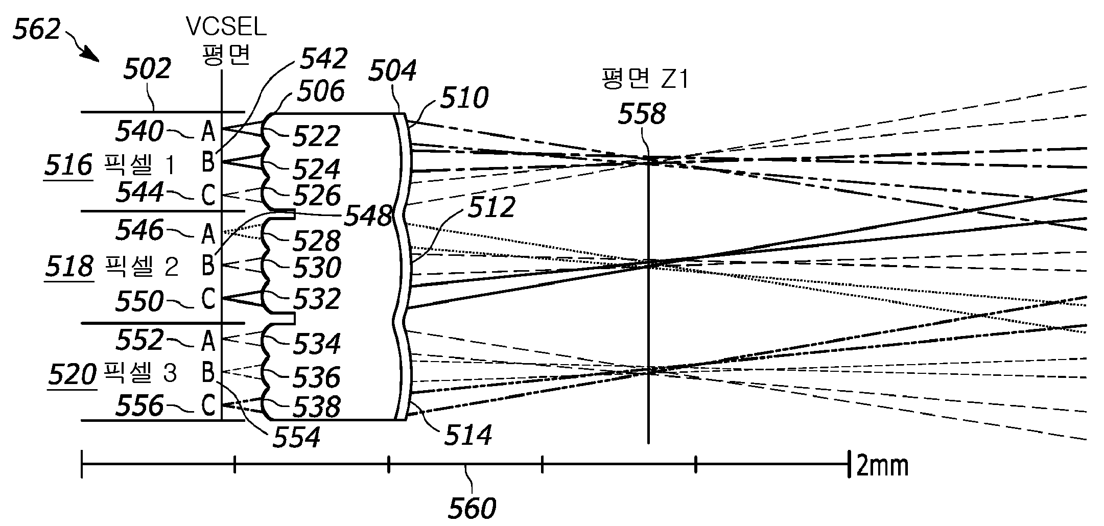
도 5a는 본 교시의 2개의 마이크로렌즈 어레이들(504, 506) 및 벌크 렌즈(508)를 사용하는 레이저 어레이(502)로부터 광학적 빔들을 투사하기 위한 송신 광학 시스템(500)의 일 실시예를 예시한다.5A illustrates one embodiment of a transmit
도 5b는 도 5a에 도시된 송신 광학 시스템(500)의 일 부분의 확대도이다. 도 5a 및 도 5b 둘 모두를 참조하면, 하나의 마이크로렌즈 어레이(504)는 레이저 어레이(502) 내의 픽셀들, 즉 픽셀 1(516) 및 픽셀 2(518), 및 픽셀 3(520)의 피치와 동일한 피치로 이격된 렌즈릿들(510, 512, 514)을 갖는다. 다른 마이크로렌즈 어레이(506)는 레이저 어레이(502)의 서브-개구들(540, 542, 544, 546, 548, 550, 552, 554, 556)의 피치와 동일한 피치로 이격된 렌즈릿들(522, 524, 526, 528, 530, 532, 534, 536, 538)을 갖는다. 따라서, 마이크로렌즈(506)는 서브-개구 당 하나의 렌즈릿을 포함하며, 마이크로렌즈(504)는 픽셀 당 하나의 렌즈릿을 포함한다. 마이크로렌즈 어레이(506)는, 각각의 서브-개구 빔이 이러한 광학 빔들의 전파 축을 변경하지 않고 포커싱되도록 각각의 서브-개구(540, 542, 544, 546, 548, 550, 552, 554, 556)에서 생성되는 광학적 빔들의 각각에 작용한다. 마이크로렌즈(504)는, 광학적 빔들이 렌즈릿들(510, 512, 514)의 후방 초점 평면 Z1(558)에서 중첩하도록 각각의 서브-개구(540, 542, 544, 546, 548, 550, 552, 554, 556)로부터의 광학적 빔들을 리다이렉트(redirect)한다. 따라서, 각각의 서브-개구(540, 542, 544, 546, 548, 550, 552, 554, 556)로부터의 광학적 빔들은 마이크로렌즈 어레이(506) 및 마이크로렌즈 어레이(504)의 결합된 작용에 의해 후방 초점 평면 Z1(558)에서 중첩 평면에 포커싱된다. 벌크 렌즈(508)는 평면 Z1(558)로부터 렌즈(508)의 초점 길이(F2)와 동일한 거리에 위치된다. 마이크로렌즈 어레이들(504, 506)의 결합은 평면 Z1(558)에서 레이저 어레이(502)와 동일한 피치를 가지고 스팟들의 어레이의 중간 실제 이미지를 생성한다. 벌크 렌즈(508)는 Z1(558)로부터 원거리 필드 내의 상이한 각도로 스팟들의 각각을 투사한다. 벌크 렌즈(508)로부터의 특정 투사 각도는 시스템의 주 광학적 축으로부터의 대응하는 어레이 스팟의 수직 거리의 함수이다.5B is an enlarged view of a portion of the transmission
본 교시의 하나의 특징은, 각각의 서브-개구로부터의 광학적 빔들을 포커싱하고 이러한 빔들을 제2 렌즈(504)의 후방 초점 평면에서 중첩되게 지향시키도록 역할하는 2개의 백-투-백 마이크로렌즈 어레이들(504, 506)의 사용이다. 확대도(562)의 눈금(560)으로부터 명백한 바와 같이, 이러한 2개의 마이크로렌즈 어레이(504, 506) 설계들은 매우 콤팩트하며, 공칭적으로 포커싱되고 중첩된 빔들이 레이저 어레이(502)로부터 2 mm 미만의 거리에서 발생한다. 일부 실시예들에 있어서, 마이크로렌즈 어레이들(504, 506)은 동일한 기판의 전방 및 후방 표면 상에 제조된다. 이는 유익하게는 조립하기에 용이한 매우 콤팩트한 시스템을 제공한다. 일부 실시예들에 있어서, 마이크로렌즈 어레이들(504, 506)은 별개의 기판들 상에 제조된다. 일부 실시예들에 있어서, 마이크로렌즈 어레이들(504, 506) 중 하나 또는 둘 모두는 굴절 광학 구성요소들일 수 있다. 일부 실시예들에 있어서, 마이크로렌즈 어레이들(504, 506) 중 하나 또는 둘 모두는 회절 광학 구성요소들일 수 있다. 일부 실시예들에 있어서, 마이크로렌즈 어레이들(504, 506) 중 하나 또는 둘 모두는 홀로그래픽 광학 구성요소들일 수 있다.One feature of the present teachings is two back-to-back microlenses that serve to focus the optical beams from each sub-aperture and direct these beams to overlap in the posterior focal plane of the
도 5c는 도 5a의 레이저 어레이(502)로부터 광학적 빔들을 투사하기 위한 송신 광학 시스템(500)에 의해 생성되는 원거리 필드 패턴(580)의 일 실시예를 예시한다. 원거리 필드 스팟들이 2개의 수직적으로 인접한 픽셀들에 대해 도시되며, 여기에서 각각의 픽셀은 50 미터 범위에서 서브-개구들의 3X3 어레이를 포함한다. 도 5a의 시스템 도면이 2차원 어레이들의 측면도를 도시하지만, 도 5c가 주 축에 수직인 평면 내의 2차원 패턴을 예시한다는 것을 유의해야 한다. 명료성을 위해 시스템의 부분들만이 예시된다. 원거리 필드 패턴(580)은 50 미터의 범위에서 0.9-미터 거리(586)만큼 분리된 2개의 작은 스팟들(582, 584)을 야기한다. 스팟들(582, 584)은 단지 2개의 픽셀들(516, 518)에 대해서만 도시된다. 픽셀들 사이에 1.06 도가 존재하며, 이는 50-미터 범위에서 0.9-미터의 분리 거리(586)를 야기한다. 픽셀-스팟-크기-대-픽셀-피치 비율은 ~ 0.1이다. 최종 해상도는 인접한 픽셀들로부터의 스팟들 사이의 스팟 분리에 상대적인 하나의 픽셀로부터의 스팟 크기에 의해 결정된다. 따라서, 본 교시의 송신 광학 시스템은 유익하게는 원거리 필드에서 훨씬 더 작은 픽셀 스팟 크기-대-픽셀-피치 비율을 제공한다. 이는 시스템 해상도를 개선하며, 또한 높은 데이터 수집 속도 및 조명 패턴들 및 타이밍 시퀀스들에서의 유연성의 지원을 포함하여 데이터 수집에 대한 다수의 이점들을 제공하는 다수의 송신 광학 시스템들의 효율적이고 확장가능한 인터리빙을 허용한다.5C illustrates one embodiment of a
도 6은 본 교시의 VCSEL 어레이(604)에 대해 정렬된 양면 마이크로렌즈 어레이(602)의 일 실시예의 단면도(600)를 예시한다. VCSEL은 5개의 픽셀들(606, 608, 610, 612, 614)을 포함한다. 각각의 픽셀(606, 608, 610, 612, 614)은 9개의 서브-개구들을 포함한다. 예를 들어, 3개의 서브-개구들(616, 618, 620)이 픽셀에 대한 단면도(600)에서 보일 수 있다. 픽셀들은 피치(622)를 가지고 어레이 내에 배열된다. 5-픽셀 렌즈릿들(624, 626, 628, 630, 632)이 기판(636)의 제1 표면(634) 상에 형성된다. 픽셀 렌즈릿들(624, 626, 628, 630, 632)은 피치(638)를 가지고 어레이 내에 배열되며, VCSEL 어레이(604) 내의 픽셀들(606, 608, 610, 612, 614)의 어레이와 매칭된다. VCSEL 어레이(604)의 서브-개구들의 피치와 매칭되는 피치(642)로 설정된 서브-개구 렌즈릿들(640)이 기판(636)의 제2 표면(638) 상에 형성된다. 이러한 마이크로렌즈 어레이(602) 구성은 양면 마이크로렌즈로 지칭될 수 있다. 하나의 특정 실시예에 있어서, 픽셀 피치는 250 μm이며 서브-개구 피치는 76 μm이다. 일부 실시예들에 있어서, 레이저 및 마이크로렌즈 어레이들(602, 604)은 1차원이다. 또한, 일부 실시예들에 있어서, 마이크로렌즈 어레이들(602, 604)은 2차원이다. 다양한 실시예들에 있어서, 마이크로렌즈 어레이들(602, 604)은 상이한 수의 픽셀들, 서브-개구들, 픽셀 렌즈릿들 및/또는 서브-개구 렌즈릿들을 포함한다. 일부 실시예들에 있어서, 픽셀 피치(622)는 서브-개구 피치(642)의 정수배가 아니다. 일부 실시예들에 있어서, 서브-개구 피치(642)는 픽셀의 경계들에 걸쳐 연장하지 않는다.6 illustrates a
일부 실시예들에 있어서, 마이크로렌즈 어레이(602)의 서브-개구 렌즈릿(640) 측면은 VCSEL 어레이(604)에 가장 가깝게 위치된다. 픽셀 렌즈릿 표면(634)은 VCSEL 어레이(602)로부터 가장 멀리에 위치되며, 여기에서 각각의 렌즈릿(624, 626, 628, 630, 632)은 픽셀 바로 위에 중심이 맞춰진다. 이러한 배치는, 예를 들어, 픽셀(610) 위의 픽셀 렌즈릿(628)에 대해 도 6에 구체적으로 예시된다. 서브-개구 렌즈릿들은 서브-개구 바로 위에 중심이 맞춰진다. 이는, 예를 들어, 서브-개구(644) 위의 서브-개구 렌즈릿(640)에 대해 도 6에 예시된다.In some embodiments, the
도 7a는 본 교시의 양면 마이크로렌즈 어레이(702)의 일 실시예의 하나의 측면을 도시하는 사시도(700)를 예시한다. 픽셀 렌즈릿들(704)은 기판(708)의 하나의 표면(706) 상에 형성된다. 렌즈릿들(704)은, 본 교시의 송신 광학 시스템의 일 실시예에서 픽셀 당 하나의 렌즈가 존재하도록, 예를 들어, VCSEL 어레이의 피치와 매칭되는 피치를 갖는다. 렌즈릿들(704)의 5X5 어레이가 사시도(700)에 예시된다. 서브-개구 렌즈릿들(712)은 기판(708)의 다른 표면(710) 상에서 보일 수 있다.7A illustrates a
도 7b는 도 7a의 양면 마이크로렌즈 어레이의 다른 측면을 도시하는 사시도(750)를 예시한다. 원(752)은 기판의 다른 표면(710) 상에 형성된 서브-개구 렌즈릿들(754)의 9X9 어레이를 강조한다. 서브-개구 렌즈릿(754) 피치는, 매칭되는 레이저들의 어레이, 예를 들어, VCSEL 어레이의 서브-개구들의 피치와 매칭된다. 픽셀 당 9개의 서브-개구 렌즈릿들이 존재한다.FIG. 7B illustrates a
도 8은 본 교시의 다수의 송신 광학 시스템들(802, 804)을 포함하는 고-해상도 LIDAR 송신 시스템(800)의 일 실시예를 예시한다. 본 교시의 하나의 특징은, 본원에서 설명되는 2개의 마이크로렌즈 어레이 구성이, 하나의 송신 광학 시스템(802)에 의해 생성되는 전체 FOV가 제2 송신 광학 시스템(804)에 의해 생성되는 전체 FOV로부터 1 픽셀 미만만큼 오프셋되도록 별개의 송신 광학 시스템들을 사용하는 것을 가능하게 만든다는 점이다. 이러한 유형의 구성은 인터리빙된 구성으로 지칭될 수 있다. 2개의 송신 광학 시스템들(802, 804)로부터의 광을 인터리빙함으로써, 인터리빙된 송신 시스템(800)을 포함하는 LIDAR 시스템의 공간 해상도가 하나의 송신 광학 시스템만을 사용하는 LIDAR 시스템에 비해 크게 개선된다.8 illustrates one embodiment of a high-resolution
인터리빙은 오직 하나의 목표 거리에서만 2개의 상이한 송신 광학 시스템들의 각각에 의해 생성되는 스팟들 사이에 균일한 간격을 가질 것이다(때때로 완벽한 인터리빙으로 지칭됨). 그러나, 송신 광학 시스템들(802, 804) 사이의 분리가 작을 수 있고, 일부 실시예들에서 분리는 약 10 밀리미터 정도이고, 일부 실시예들에서 목표 거리들은 약 10 미터 정도이기 때문에, 심지어 불완전한 인터리빙도 용인가능하고 해상도를 개선한다. 따라서, 송신 광학 시스템들(802, 804)을 인터리빙함으로써 개선된 해상도는 본 교시의 송신 광학 시스템들을 사용하여 목표 거리들의 범위에 걸쳐 가능하다. 도 8은, 송신 광학 시스템(802)으로부터의 스팟들(808)의 제1 어레이 및 송신 광학 시스템(804)으로부터의 스팟들(810)의 제2 어레이의 인터리빙을 예시하는, 하나의 목표 거리에 인터리빙된 스팟들(806)의 어레이를 도시한다.Interleaving will have uniform spacing between spots created by each of two different transmit optical systems at only one target distance (sometimes referred to as perfect interleaving). However, even incomplete interleaving because the separation between the transmit
도 9a는, 도 3a에 예시된 바와 같은, 2개의 통상적인 벌크 렌즈들을 사용하는 레이저 어레이로부터 광학적 빔들을 투사하기 위한 시스템을 사용하는 단일 솔리드-상태 LIDAR 송신기에 대한 원거리 필드 패턴(900)을 예시한다. 픽셀 스팟 크기(902) 및 픽셀 피치(904)는 공칭적으로 동일하다. 픽셀 스팟 크기(902)는 전체 픽셀이다. 모든 서브-개구 스팟들은 그 픽셀 및 연관된 서브-개구들에 에너지를 공급하기 위해 인가되는 제어 신호에 의해 조명된다. 이와 같이, 2개의 벌크 렌즈들만을 사용하며 마이크로렌즈들을 사용하지 않는 2개의 상이한 송신 광학 시스템들로부터의 픽셀 스팟들(906)을 인터리빙하는 것이 불가능하다. 원거리 필드에서 픽셀-스팟-크기-대-픽셀-피치는 이러한 시스템에 대해 1에 가깝다. 결과적으로, 2개의 송신 광학 시스템들을 사용하여 스팟들을 인터리빙하고 개선된 해상도를 제공하기 위한 공간이 존재하지 않는다.9A illustrates a
도 9b는, 예를 들어, 도 4a에 도시된 바와 같은, 하나의 마이크로렌즈 어레이 및 하나의 벌크 렌즈를 사용하는 레이저 어레이로부터 광학적 빔들을 투사하기 위한 시스템을 사용하는 다수의 인터리빙된 솔리드-상태 LIDAR 송신기들에 대한 원거리 필드 패턴(930)을 예시한다. 이러한 구성에서, 단일의 에너지가 공급된 픽셀로부터의 스팟 크기는 픽셀 FOV 피치(934)보다 더 작은 음영진 스팟(932)으로 도시된다. 원거리 필드에서 픽셀-스팟-크기-대-픽셀-피치의 비율은 이러한 시스템에 대해 0.5에 가깝다. 따라서, 이러한 경우에, 예를 들어, 4개의 송신 광학 시스템들을 인터리빙하는 것이 가능하다. 이는, 4개의 상이한 송신 광학 시스템들과 연관된 4개의 상이한 픽셀 스팟들(932, 936, 938, 940)을 생성한다. 4개의 상이한 송신 광학 시스템들로부터의 스팟들의 인터리빙은 각각의 차원에서 2 배만큼 공간 해상도를 증가시킨다.9B shows multiple interleaved solid-state LIDARs using a system for projecting optical beams from a laser array using one microlens array and one bulk lens, for example as shown in FIG. 4A ; A
도 9c는 본 교시의 2개의 마이크로렌즈 어레이들 및 하나의 통상적인 벌크 렌즈를 사용하는 레이저 어레이로부터 광학적 빔들을 투사하는 송신 광학 시스템의 일 실시예를 사용하는 다수의 인터리빙된 솔리드 상태 LIDAR 송신기들에 대한 원거리 필드 패턴(950)을 예시한다. 송신 광학 시스템의 이러한 실시예는, 예를 들어, 도 5a에 도시된 실시예일 수 있다. 이러한 구성에서, 단일 픽셀 스팟(954)의 픽셀 스팟 크기(952)는 픽셀 FOV 피치(956)에 비해 매우 작다. 일부 실시예들에 있어서, 원거리 필드에서 픽셀-스팟-크기-대-픽셀-피치의 비율은 0.1보다 더 작다. 공간 해상도를 증가시키기 위해 적어도 9개의 송신 광학 시스템들로부터의 스팟들(954)을 인터리빙하는 것이 가능하다. 상이한 음영들이 상이한 송신 광학 시스템들로부터의 픽셀 스팟들을 예시하기 위해 사용된다.9C illustrates multiple interleaved solid state LIDAR transmitters using one embodiment of a transmit optical system that projects optical beams from a laser array using two microlens arrays and one conventional bulk lens of the present teachings. A
도 9a 내지 도 9c와 관련하여 설명된 예들은 픽셀들의 3X3 그리드를 갖는 VCSEL 어레이에 의해 생성된 원거리 필드 패턴들(900, 930, 950)을 예시하며, 여기에서 각각의 픽셀은 서브-개구들의 3X3 그리드를 포함한다. 픽셀들 및/또는 서브-개구 크기들 및/또는 형상들 모두에 대해 상이한 어레이 크기들 및/또는 형상들로 조정하는 것은 간단한 확장이다.The examples described in connection with FIGS. 9A-9C illustrate
따라서, VCSEL 픽셀 서브-개구 방출기들로부터의 광학적 빔들을 포커싱하기 위한 서브-개구 마이크로렌즈들, 서브-개구 광학적 빔들을 중첩 지점에서의 그들의 초점으로 리다이렉트하기 위한 픽셀 마이크로렌즈들, 및 각각의 픽셀 내의 서브-개구 빔들을 원거리 필드의 상이한 각도에 투사하기 위한 벌크 렌즈의 조합을 사용하는 송신 광학 시스템들의 하나의 특징은, 이러한 송신 광학 시스템이 송신 광학 시스템들의 인터리빙을 허용하기에 충분하게 공간 해상도를 개선한다는 점이다. 이러한 개선은 부분적으로, 더 작은 원거리 필드 픽셀-스팟-크기-대-픽셀-피치 비율이 달성되기 때문이다. 원거리 필드에서의 상이한 투사 각도들은, 벌크 렌즈의 주 축 또는 중심에 대한 특정 픽셀 광학적 빔의 위치에 기초한다. 따라서, 상이한 초점 길이들 및 위치들을 갖는 벌크 렌즈들을 사용함으로써, 다양한 원거리-필드 투사 각도들이 달성될 수 있다.Thus, sub-aperture microlenses for focusing optical beams from VCSEL pixel sub-aperture emitters, pixel microlenses for redirecting sub-aperture optical beams to their focus at the point of overlap, and within each pixel One feature of transmit optical systems that use a combination of bulk lenses to project sub-aperture beams at different angles of the far field is that such transmit optical systems improve spatial resolution sufficiently to allow interleaving of the transmit optical systems. that it does This improvement is partly because a smaller far field pixel-spot-size-to-pixel-pitch ratio is achieved. The different projection angles in the far field are based on the position of a particular pixel optical beam with respect to the main axis or center of the bulk lens. Thus, by using bulk lenses with different focal lengths and positions, various far-field projection angles can be achieved.
등가물들equivalents
출원인의 교시가 다양한 실시예들과 관련하여 설명되었지만, 출원인의 교시가 이러한 실시예들로 한정되도록 의도되지 않는다. 반대로, 출원인의 교시는, 당업자들에 의해 이해될 바와 같이, 본 교시의 사상 및 범위로부터 벗어나지 않고 이루어질 수 있는, 다양한 대안예들, 수정예들, 및 등가물들을 포괄한다.Although Applicants' teachings have been described in connection with various embodiments, it is not intended that Applicants' teachings be limited to these embodiments. On the contrary, Applicants' teachings cover various alternatives, modifications, and equivalents, which may be made without departing from the spirit and scope of the present teachings, as will be understood by those skilled in the art.
Claims (29)
a) 레이저 어레이로서,
i) 제1 서브-개구 간격을 가지고 위치된 제1 및 제2 서브-개구를 포함하는 제1 레이저 픽셀로서, 상기 제1 및 제2 서브-개구의 각각은 에너지가 공급될 때 서브-개구 빔을 생성하는, 상기 제1 레이저 픽셀; 및
ii) 제2 서브-개구 간격을 가지고 위치된 제1 및 제2 서브-개구를 포함하는 제2 레이저 픽셀로서, 상기 제1 및 제2 서브-개구의 각각은 에너지가 공급될 때 서브-개구 빔을 생성하며, 상기 제1 및 제2 레이저 픽셀은 픽셀 간격을 가지고 서로에 대해 위치되는, 상기 제2 레이저 픽셀을 포함하는, 상기 레이저 어레이;
b) 상기 제1 서브-개구 간격을 가지고 위치되는 제1 서브-개구 렌즈릿(lenslet) 및 제2 서브-개구 렌즈릿을 포함하며, 상기 제2 서브-개구 간격을 가지고 위치되는 제3 서브-개구 렌즈릿 및 제4 서브-개구 렌즈릿을 포함하는 제1 마이크로렌즈로서, 상기 제1 마이크로렌즈는 상기 제1 레이저 픽셀의 상기 제1 서브-개구에 의해 생성되는 상기 제1 서브-개구 빔의 광학적 경로 내에 상기 제1 서브-개구 렌즈릿이 존재하도록 위치되고 상기 제2 레이저 픽셀의 상기 제1 서브-개구에 의해 생성되는 상기 제1 서브-개구 빔의 광학적 경로 내에 상기 제3 서브-개구 렌즈릿이 존재하도록 위치되며, 상기 제1 마이크로렌즈는 상기 제1 레이저 픽셀의 상기 제1 및 제2 서브-개구에 의해 생성되는 상기 제1 및 제2 서브-개구 빔들을 포커싱하도록 그리고 상기 제2 레이저 픽셀의 상기 제1 및 제2 서브-개구에 의해 생성되는 상기 제1 및 제2 서브-개구 빔들을 포커싱하도록 구성되는, 상기 제1 마이크로렌즈;
c) 상기 픽셀 간격을 가지고 서로에 대해 위치되는 제1 픽셀 렌즈릿 및 제2 픽셀 렌즈릿을 포함하는 제2 마이크로렌즈로서, 상기 제1 픽셀 렌즈릿은 상기 제1 레이저 픽셀의 상기 제1 및 제2 서브-개구에 의해 생성되는 상기 제1 및 제2 서브-개구 빔들 모두의 광학적 경로 내에 존재하고, 상기 제2 마이크로렌즈는 상기 제1 레이저 픽셀의 상기 제1 및 제2 서브-개구에 의해 생성되는 상기 제1 및 제2 서브-개구 빔들이 평면에서 중첩하도록 상기 제1 레이저 픽셀의 상기 제1 및 제2 서브-개구에 의해 생성되는 상기 제1 및 제2 서브-개구 빔들을 지향시키도록 구성되는, 상기 제2 마이크로렌즈; 및
d) 상기 제1 레이저 픽셀의 상기 제1 및 제2 서브-개구에 의해 생성되는 상기 제1 및 제2 서브-개구 빔들의 경로 내에 위치되는 렌즈로서, 상기 렌즈는 LIDAR 시스템의 희망되는 공간 해상도를 달성하기 위하여 상기 제1 레이저 픽셀의 상기 제1 서브-개구에 의해 생성되는 상기 제1 서브-개구 빔 및 상기 제2 레이저 픽셀의 상기 제1 서브-개구에 의해 생성되는 상기 제1 서브-개구 빔을 원거리 필드에 상이한 각도들을 가지고 투사하도록 구성되는, 상기 렌즈를 포함하는, 솔리드-상태 LIDAR 송신기.A solid-state Light Detection and Ranging (LIDAR) transmitter comprising:
a) a laser array comprising:
i) a first laser pixel comprising first and second sub-apertures positioned with a first sub-aperture spacing, each of said first and second sub-apertures being a sub-aperture beam when energized the first laser pixel generating a; and
ii) a second laser pixel comprising first and second sub-apertures positioned with a second sub-aperture spacing, each of said first and second sub-apertures being a sub-aperture beam when energized the laser array comprising the second laser pixels, wherein the first and second laser pixels are positioned relative to each other with a pixel spacing;
b) a third sub-aperture comprising a first sub-aperture lenslet and a second sub-aperture lenslet positioned with the first sub-aperture spacing, the third sub-aperture positioned with the second sub-aperture spacing a first microlens comprising an aperture lenslet and a fourth sub-aperture lenslet, wherein the first microlens is a portion of the first sub-aperture beam generated by the first sub-aperture of the first laser pixel. The third sub-aperture lens is positioned such that there is the first sub-aperture lenslet in the optical path and the third sub-aperture lens is in the optical path of the first sub-aperture beam produced by the first sub-aperture of the second laser pixel. lit to exist, the first microlens to focus the first and second sub-aperture beams generated by the first and second sub-apertures of the first laser pixel and the second laser the first microlens configured to focus the first and second sub-aperture beams generated by the first and second sub-aperture of a pixel;
c) a second microlens comprising first and second pixel lenslets positioned relative to each other with said pixel spacing, said first pixel lenslets comprising said first and second pixel lenslets of said first laser pixel in the optical path of both the first and second sub-aperture beams created by two sub-apertures, the second microlens being produced by the first and second sub-apertures of the first laser pixel and direct the first and second sub-aperture beams produced by the first and second sub-aperture of the first laser pixel such that the first and second sub-aperture beams that become being the second microlens; and
d) a lens positioned in the path of the first and second sub-aperture beams created by the first and second sub-apertures of the first laser pixel, the lens having a desired spatial resolution of the LIDAR system the first sub-aperture beam produced by the first sub-aperture of the first laser pixel and the first sub-aperture beam produced by the first sub-aperture of the second laser pixel to achieve and the lens configured to project a ?
a) 레이저 어레이 및 마이크로렌즈 어레이를 포함하며, 상기 레이저 어레이에 의해 생성되는 복수의 광학적 빔을 투사하여 원거리 필드에서 제1 스팟 크기 및 제1 픽셀 피치를 포함하는 복수의 제1 픽셀 스팟들을 형성하도록 구성되는 제1 송신 광학 시스템; 및
b) 레이저 어레이 및 마이크로렌즈 어레이를 포함하며, 상기 레이저 어레이에 의해 생성되는 복수의 광학적 빔을 투사하여 상기 원거리 필드에서 제2 스팟 크기 및 제2 픽셀 피치를 포함하는 복수의 제2 픽셀 스팟들을 형성하도록 구성되는 제2 송신 광학 시스템으로서, 상기 제1 송신 광학 시스템 및 상기 제2 송신 광학 시스템은 상기 원거리 필드에서 상기 복수의 제1 픽셀 스팟들이 상기 복수의 제2 픽셀 스팟들과 인터리빙되도록 위치되며, 상기 복수의 제1 픽셀 스팟들의 원거리 필드 픽셀-스팟-크기-대-픽셀-피치 비율은 1보다 작은, 상기 제2 송신 광학 시스템을 포함하는, 솔리드-상태 LIDAR 송신기.A solid-state Light Detection and Ranging (LIDAR) transmitter comprising:
a) comprising a laser array and a microlens array to project a plurality of optical beams produced by the laser array to form a first plurality of pixel spots comprising a first spot size and a first pixel pitch in a far field; a first transmission optical system configured; and
b) comprising a laser array and a microlens array, projecting a plurality of optical beams generated by the laser array to form a second plurality of pixel spots in the far field comprising a second spot size and a second pixel pitch a second transmit optical system configured to and a far field pixel-spot-size-to-pixel-pitch ratio of the plurality of first pixel spots is less than one.
28. The solid-state LIDAR transmitter of claim 27, wherein the second microlens is on the same substrate as the first microlens.
Applications Claiming Priority (3)
| Application Number | Priority Date | Filing Date | Title |
|---|---|---|---|
| US201962881354P | 2019-07-31 | 2019-07-31 | |
| US62/881,354 | 2019-07-31 | ||
| PCT/US2020/043979 WO2021021872A1 (en) | 2019-07-31 | 2020-07-29 | High-resolution solid-state lidar transmitter |
Publications (1)
| Publication Number | Publication Date |
|---|---|
| KR20220038691A true KR20220038691A (en) | 2022-03-29 |
Family
ID=74228466
Family Applications (1)
| Application Number | Title | Priority Date | Filing Date |
|---|---|---|---|
| KR1020227003018A Pending KR20220038691A (en) | 2019-07-31 | 2020-07-29 | High-Resolution Solid-State LIDAR Transmitter |
Country Status (6)
| Country | Link |
|---|---|
| US (2) | US12222445B2 (en) |
| EP (1) | EP4004587A4 (en) |
| JP (3) | JP2022547389A (en) |
| KR (1) | KR20220038691A (en) |
| CN (1) | CN114174869B (en) |
| WO (1) | WO2021021872A1 (en) |
Cited By (11)
| Publication number | Priority date | Publication date | Assignee | Title |
|---|---|---|---|---|
| US11513195B2 (en) | 2019-06-10 | 2022-11-29 | OPSYS Tech Ltd. | Eye-safe long-range solid-state LIDAR system |
| US11740331B2 (en) | 2017-07-28 | 2023-08-29 | OPSYS Tech Ltd. | VCSEL array LIDAR transmitter with small angular divergence |
| US11762068B2 (en) | 2016-04-22 | 2023-09-19 | OPSYS Tech Ltd. | Multi-wavelength LIDAR system |
| US11802943B2 (en) | 2017-11-15 | 2023-10-31 | OPSYS Tech Ltd. | Noise adaptive solid-state LIDAR system |
| US11846728B2 (en) | 2019-05-30 | 2023-12-19 | OPSYS Tech Ltd. | Eye-safe long-range LIDAR system using actuator |
| US11906663B2 (en) | 2018-04-01 | 2024-02-20 | OPSYS Tech Ltd. | Noise adaptive solid-state LIDAR system |
| US11927694B2 (en) | 2017-03-13 | 2024-03-12 | OPSYS Tech Ltd. | Eye-safe scanning LIDAR system |
| US11965964B2 (en) | 2019-04-09 | 2024-04-23 | OPSYS Tech Ltd. | Solid-state LIDAR transmitter with laser control |
| US12055629B2 (en) | 2019-06-25 | 2024-08-06 | OPSYS Tech Ltd. | Adaptive multiple-pulse LIDAR system |
| US12153163B2 (en) | 2018-08-03 | 2024-11-26 | OPSYS Tech Ltd. | Distributed modular solid-state lidar system |
| US12222445B2 (en) | 2019-07-31 | 2025-02-11 | OPSYS Tech Ltd. | High-resolution solid-state LIDAR transmitter |
Families Citing this family (8)
| Publication number | Priority date | Publication date | Assignee | Title |
|---|---|---|---|---|
| US20210382142A1 (en) * | 2020-06-08 | 2021-12-09 | Pointcloud Inc. | Microlens array lidar system |
| EP4308962A4 (en) * | 2021-03-17 | 2025-02-19 | Neural Propulsion Systems, Inc. | SYSTEMS, METHODS AND DEVICES FOR COMBINING MULTIPLE ARRAYS OF OPTICAL COMPONENTS |
| KR20240005752A (en) * | 2021-05-11 | 2024-01-12 | 옵시스 테크 엘티디 | Pixel mapping solid-state LIDAR transmitter system and method |
| US20230033889A1 (en) * | 2021-07-27 | 2023-02-02 | Fujifilm Business Innovation Corp. | Light-emitting element array, optical device, optical measurement device, and method for manufacturing light-emitting element array |
| US20230032341A1 (en) * | 2021-07-27 | 2023-02-02 | Fujifilm Business Innovation Corp. | Light-emitting element array, optical device, optical measurement device, and method for manufacturing light-emitting element array |
| US20220011470A1 (en) * | 2021-09-23 | 2022-01-13 | Anders Grunnet-Jepsen | Optic pieces having integrated lens arrays |
| US20240393551A1 (en) * | 2023-05-22 | 2024-11-28 | Apple Inc. | Pattern projector |
| US20250306177A1 (en) * | 2024-03-26 | 2025-10-02 | OPSYS Tech Ltd. | LiDAR Transmitter with Flat Optics |
Family Cites Families (285)
| Publication number | Priority date | Publication date | Assignee | Title |
|---|---|---|---|---|
| JPS549465Y2 (en) | 1973-12-29 | 1979-05-02 | ||
| US5157257A (en) | 1990-06-18 | 1992-10-20 | Lasen, Inc. | Mid-infrared light hydrocarbon DIAL LIDAR |
| JP3111599B2 (en) | 1992-03-02 | 2000-11-27 | 松下電器産業株式会社 | Optoelectronic integrated circuits |
| JP3042278B2 (en) | 1993-09-17 | 2000-05-15 | 三菱電機株式会社 | Distance measuring device |
| JPH07253460A (en) | 1994-03-14 | 1995-10-03 | Nikon Corp | Distance measuring device |
| JPH08280173A (en) | 1995-02-08 | 1996-10-22 | Meidensha Corp | Capacitor charging device |
| AU6136096A (en) | 1995-06-22 | 1997-01-22 | 3Dv Systems Ltd. | Telecentric 3d camera and method |
| JPH10126007A (en) | 1996-10-21 | 1998-05-15 | Fuji Xerox Co Ltd | Two-dimensional semiconductor laser array light emitting device and its driving method |
| US5909296A (en) | 1997-04-04 | 1999-06-01 | The United States Of America As Represented By The Secretary Of The Air Force | Effective wide angle beam steering using spherical laser diode arrays |
| DE19717399C2 (en) | 1997-04-24 | 2001-05-23 | Martin Spies | Device for determining the distance and type of objects and the visibility |
| US6246708B1 (en) | 1997-08-27 | 2001-06-12 | Xerox Corporation | Semiconductor laser with associated electronic components integrally formed therewith |
| WO1999042856A2 (en) | 1998-02-19 | 1999-08-26 | Amerigon Inc. | High performance vehicle radar system |
| JP2000056020A (en) | 1998-08-07 | 2000-02-25 | Honda Motor Co Ltd | Object detection device |
| US6775480B1 (en) | 1998-09-10 | 2004-08-10 | Nortel Networks Limited | Free space optical interconnect system |
| JP2000147604A (en) | 1998-11-13 | 2000-05-26 | Matsushita Electric Ind Co Ltd | Range finder |
| US6560262B1 (en) | 1999-01-26 | 2003-05-06 | Triquint Technology Holding Co. | Vertical cavity surface emitting laser array and a process for making same |
| US6959870B2 (en) | 1999-06-07 | 2005-11-01 | Metrologic Instruments, Inc. | Planar LED-based illumination array (PLIA) chips |
| GB0000908D0 (en) | 2000-01-14 | 2000-03-08 | Scient Generics Ltd | Parallel free-space optical communications |
| DE10004398A1 (en) | 2000-02-02 | 2001-08-16 | Infineon Technologies Ag | VCSEL with monolithically integrated photodetector |
| AT408818B (en) | 2000-02-11 | 2002-03-25 | Riegl Laser Measurement Sys | METHOD FOR RECORDING AN OBJECT SPACE |
| EP1160540A1 (en) | 2000-06-03 | 2001-12-05 | Leica Geosystems AG | Optical rangefinder |
| RU2172560C1 (en) | 2000-06-08 | 2001-08-20 | Васильев Владимир Павлович | Optical communication facility |
| US6353502B1 (en) * | 2000-06-13 | 2002-03-05 | Eastman Kodak Company | VCSEL field correction |
| US6888871B1 (en) | 2000-07-12 | 2005-05-03 | Princeton Optronics, Inc. | VCSEL and VCSEL array having integrated microlenses for use in a semiconductor laser pumped solid state laser system |
| US6680788B1 (en) | 2000-10-12 | 2004-01-20 | Mcnc | Scanning apparatus and associated method |
| FR2816264B1 (en) | 2000-11-09 | 2003-02-21 | Thomas Bleiner | VISUAL SIGNALING DEVICE ADAPTABLE TO A VEHICLE |
| JP3789757B2 (en) | 2001-01-22 | 2006-06-28 | 小糸工業株式会社 | Object detection device |
| US20020117340A1 (en) | 2001-01-31 | 2002-08-29 | Roger Stettner | Laser radar based collision avoidance system for stationary or moving vehicles, automobiles, boats and aircraft |
| AUPR301401A0 (en) | 2001-02-09 | 2001-03-08 | Commonwealth Scientific And Industrial Research Organisation | Lidar system and method |
| US6556282B2 (en) | 2001-09-04 | 2003-04-29 | Rosemount Aerospace, Inc. | Combined LOAS and LIDAR system |
| EP1446703A2 (en) * | 2001-11-07 | 2004-08-18 | Applied Materials, Inc. | Optical spot grid array printer |
| NO316632B1 (en) | 2001-11-16 | 2004-03-15 | Thin Film Electronics Asa | Matrix addressable optoelectronic apparatus and electrode assembly in the same |
| JP2003258359A (en) | 2002-03-06 | 2003-09-12 | Sharp Corp | Optical system |
| JP3931127B2 (en) | 2002-09-03 | 2007-06-13 | オリンパス株式会社 | LIGHTING DEVICE AND DISPLAY DEVICE USING THE SAME |
| US7873083B2 (en) | 2002-10-17 | 2011-01-18 | Lumenis Ltd. | System, method, and apparatus to provide laser beams of two or more wavelengths |
| US20040120717A1 (en) | 2002-12-18 | 2004-06-24 | Lightpointe Communications, Inc. | Extended source free-space optical communication system |
| US6860350B2 (en) | 2002-12-20 | 2005-03-01 | Motorola, Inc. | CMOS camera with integral laser ranging and velocity measurement |
| US7065112B2 (en) | 2003-05-12 | 2006-06-20 | Princeton Optronics, Inc. | Wavelength locker |
| US6788715B1 (en) | 2003-05-30 | 2004-09-07 | Princeton Optronics | Stabilized laser using multiphoton absorption to reduce intensity fluctuations |
| JP2004361315A (en) | 2003-06-06 | 2004-12-24 | Nissan Motor Co Ltd | Radar equipment |
| EP1511138B1 (en) | 2003-09-01 | 2010-08-04 | Avalon Photonics AG | A high power top emitting vertical cavity surface emitting laser |
| US7016393B2 (en) * | 2003-09-22 | 2006-03-21 | Coherent, Inc. | Apparatus for projecting a line of light from a diode-laser array |
| JP3940395B2 (en) | 2003-11-14 | 2007-07-04 | パイオニア株式会社 | Method and apparatus for driving light emitting element |
| DE102004002221B3 (en) | 2004-01-15 | 2005-05-19 | Unique-M.O.D.E. Ag | Optical symmetry device for high power laser diode array used in materials processing, medical, telecommunications, illumination, display, analysis, printing or photographic device, or for laser pumping |
| US7209502B2 (en) | 2004-02-12 | 2007-04-24 | Avago Technologies Ecbu Ip (Singapore) Pte. Ltd. | Open loop laser power control for optical navigation devices and optical systems |
| US7026600B2 (en) | 2004-02-26 | 2006-04-11 | Rosemount Aerospace Inc. | System and method of identifying an object in a laser beam illuminated scene based on material types |
| JP3962929B2 (en) | 2004-05-18 | 2007-08-22 | 防衛省技術研究本部長 | Laser distance image generating apparatus and method |
| KR20070065439A (en) | 2004-10-15 | 2007-06-22 | 트리코 프로덕츠 코포레이션 오브 테네시 | Object Detection System with VCSEL Diode Array |
| WO2006083349A2 (en) | 2004-11-19 | 2006-08-10 | Science & Engineering Services, Inc. | Enhanced portable digital lidar system |
| JP2006162386A (en) | 2004-12-06 | 2006-06-22 | Canon Inc | 3D model generation apparatus, 3D model generation system, and 3D model generation program |
| US7440084B2 (en) | 2004-12-16 | 2008-10-21 | Arete' Associates | Micromechanical and related lidar apparatus and method, and fast light-routing components |
| US7566861B2 (en) | 2005-04-27 | 2009-07-28 | Sanyo Electric Co., Ltd. | Detection device controlled by driving speed and driving direction |
| US7652752B2 (en) | 2005-07-14 | 2010-01-26 | Arete' Associates | Ultraviolet, infrared, and near-infrared lidar system and method |
| JP2007058163A (en) | 2005-07-27 | 2007-03-08 | Ricoh Co Ltd | LIGHT SOURCE DEVICE, LIGHT MODULATION DEVICE, DISPLAY DEVICE, CONCENTRATION LIGHTING DEVICE, AND PROJECTION COLOR DISPLAY DEVICE |
| US7339670B2 (en) | 2005-07-29 | 2008-03-04 | Lockheed Martin Coherent Technologies, Inc. | Wavelength normalized depolarization ratio lidar |
| US20070071056A1 (en) | 2005-09-09 | 2007-03-29 | Ye Chen | Laser ranging with large-format VCSEL array |
| US7417717B2 (en) | 2005-10-05 | 2008-08-26 | Utah State University | System and method for improving lidar data fidelity using pixel-aligned lidar/electro-optic data |
| US7253386B2 (en) | 2005-12-12 | 2007-08-07 | Xerox Corporation | Method and apparatus for monitoring and controlling laser intensity in a ROS scanning system |
| US7936448B2 (en) | 2006-01-27 | 2011-05-03 | Lightwire Inc. | LIDAR system utilizing SOI-based opto-electronic components |
| EP1813964B1 (en) | 2006-01-29 | 2010-09-15 | Rafael-Armament Development Authority Ltd. | LADAR with passive fibre-optical scanner |
| US7544945B2 (en) | 2006-02-06 | 2009-06-09 | Avago Technologies General Ip (Singapore) Pte. Ltd. | Vertical cavity surface emitting laser (VCSEL) array laser scanner |
| US8050863B2 (en) | 2006-03-16 | 2011-11-01 | Gray & Company, Inc. | Navigation and control system for autonomous vehicles |
| ATE523806T1 (en) | 2006-03-30 | 2011-09-15 | Cambridge Mechatronics Ltd | CAMERA LENS ACTUATOR |
| WO2007138548A1 (en) | 2006-06-01 | 2007-12-06 | Koninklijke Philips Electronics N.V. | Optimizing focus crosstalk cancelling |
| JP2008015434A (en) | 2006-07-10 | 2008-01-24 | Nippon Telegr & Teleph Corp <Ntt> | Optical module and manufacturing method thereof |
| US7969558B2 (en) | 2006-07-13 | 2011-06-28 | Velodyne Acoustics Inc. | High definition lidar system |
| US7773204B1 (en) | 2006-07-20 | 2010-08-10 | United States Of America As Represented By The Secretary Of The Navy | Apparatus and method for spatial encoding of a search space |
| EP1901093B1 (en) | 2006-09-15 | 2018-11-14 | Triple-IN Holding AG | Capture of distance images |
| US7701558B2 (en) | 2006-09-22 | 2010-04-20 | Leica Geosystems Ag | LIDAR system |
| CN100429478C (en) | 2007-01-15 | 2008-10-29 | 哈尔滨工业大学 | Measurement method of laser beam divergence angle based on microlens array |
| US8072581B1 (en) | 2007-01-19 | 2011-12-06 | Rockwell Collins, Inc. | Laser range finding system using variable field of illumination flash lidar |
| DE102007011804A1 (en) | 2007-01-25 | 2008-07-31 | Osram Opto Semiconductors Gmbh | Measuring arrangement and measuring system |
| US7746450B2 (en) | 2007-08-28 | 2010-06-29 | Science Applications International Corporation | Full-field light detection and ranging imaging system |
| JP5169136B2 (en) | 2007-10-22 | 2013-03-27 | 株式会社デンソー | Laser beam irradiation device |
| US7963447B2 (en) | 2007-11-30 | 2011-06-21 | Symbol Technologies, Inc. | Enhanced monitoring of laser output power in electro-optical readers |
| DE102008062544B4 (en) | 2007-12-20 | 2017-11-09 | Denso Corporation | Laser array circuit |
| JP4831151B2 (en) | 2007-12-20 | 2011-12-07 | 株式会社デンソー | Laser array drive circuit |
| JP2009204691A (en) | 2008-02-26 | 2009-09-10 | Toyota Central R&D Labs Inc | Optical scanner, laser radar device and optical scanning method |
| DE102008022941A1 (en) | 2008-02-29 | 2009-09-03 | Osram Opto Semiconductors Gmbh | Sensor system with a lighting device and a detector device |
| US7702191B1 (en) | 2008-03-13 | 2010-04-20 | Compass Electro-Optical Systems Ltd | Electro-optical chip assembly |
| US20090273770A1 (en) | 2008-04-30 | 2009-11-05 | Honeywell International Inc. | Systems and methods for safe laser imaging, detection and ranging (lidar) operation |
| US8301027B2 (en) | 2008-05-02 | 2012-10-30 | Massachusetts Institute Of Technology | Agile-beam laser array transmitter |
| CN103090819A (en) | 2008-10-06 | 2013-05-08 | 曼蒂斯影像有限公司 | Method and system for providing three-dimensional and range inter-planar estimation |
| JP2010091855A (en) | 2008-10-09 | 2010-04-22 | Denso Corp | Laser beam irradiation device |
| US10038304B2 (en) | 2009-02-17 | 2018-07-31 | Trilumina Corp. | Laser arrays for variable optical properties |
| US7949024B2 (en) | 2009-02-17 | 2011-05-24 | Trilumina Corporation | Multibeam arrays of optoelectronic devices for high frequency operation |
| US20130223846A1 (en) | 2009-02-17 | 2013-08-29 | Trilumina Corporation | High speed free-space optical communications |
| JP2010256291A (en) | 2009-04-28 | 2010-11-11 | Toyota Motor Corp | Distance imaging device |
| CN101545582B (en) | 2009-05-05 | 2011-01-05 | 浙江大学 | Semiconductor laser array beam shaping illumination system |
| US8675181B2 (en) | 2009-06-02 | 2014-03-18 | Velodyne Acoustics, Inc. | Color LiDAR scanner |
| JP5515445B2 (en) | 2009-06-19 | 2014-06-11 | 富士ゼロックス株式会社 | Surface emitting semiconductor laser, surface emitting semiconductor laser device, optical transmission device, and information processing device |
| KR101733422B1 (en) | 2009-08-20 | 2017-05-10 | 코닌클리케 필립스 엔.브이. | Laser device with configurable intensity distribution |
| WO2011123483A1 (en) | 2010-03-31 | 2011-10-06 | Omron Scientific Technologies, Inc | Method and apparatus for generating texture in a three-dimensional scene |
| KR20110111090A (en) | 2010-04-02 | 2011-10-10 | 엘지이노텍 주식회사 | Light emitting diode lens and liquid crystal display device including the same |
| WO2011146523A2 (en) | 2010-05-17 | 2011-11-24 | Velodyne Acoustics, Inc. | High definition lidar system |
| CA2802784C (en) | 2010-06-28 | 2016-03-15 | Institut National D'optique | Method and apparatus for compensating for a parameter change in a synthetic aperture imaging system |
| US8736818B2 (en) | 2010-08-16 | 2014-05-27 | Ball Aerospace & Technologies Corp. | Electronically steered flash LIDAR |
| US8488055B2 (en) | 2010-09-30 | 2013-07-16 | Apple Inc. | Flash synchronization using image sensor interface timing signal |
| KR101326555B1 (en) | 2010-10-29 | 2013-11-08 | 다이니폰 인사츠 가부시키가이샤 | Method and apparatus for washing mold for imprinting applications, and process for producing mold for imprinting applications |
| EP2469294A1 (en) | 2010-12-23 | 2012-06-27 | André Borowski | 2D/3D real-time imager and corresponding imaging methods |
| EP2469295A1 (en) | 2010-12-23 | 2012-06-27 | André Borowski | 3D landscape real-time imager and corresponding imaging methods |
| EP2469301A1 (en) | 2010-12-23 | 2012-06-27 | André Borowski | Methods and devices for generating a representation of a 3D scene at very high speed |
| DE102011005740A1 (en) | 2011-03-17 | 2012-09-20 | Robert Bosch Gmbh | Measuring device for measuring a distance between the measuring device and a target object by means of optical measuring radiation |
| WO2012172526A1 (en) | 2011-06-17 | 2012-12-20 | Leddartech Inc. | System and method for traffic side detection and characterization |
| US20160025993A1 (en) | 2014-07-28 | 2016-01-28 | Apple Inc. | Overlapping pattern projector |
| JP5858688B2 (en) | 2011-08-30 | 2016-02-10 | スタンレー電気株式会社 | Distance image generator |
| JP2013113669A (en) | 2011-11-28 | 2013-06-10 | Mitsubishi Electric Corp | Laser radar device |
| US20130163627A1 (en) | 2011-12-24 | 2013-06-27 | Princeton Optronics | Laser Illuminator System |
| US8675706B2 (en) | 2011-12-24 | 2014-03-18 | Princeton Optronics Inc. | Optical illuminator |
| US8576885B2 (en) | 2012-02-09 | 2013-11-05 | Princeton Optronics, Inc. | Optical pump for high power laser |
| US20150253428A1 (en) | 2013-03-15 | 2015-09-10 | Leap Motion, Inc. | Determining positional information for an object in space |
| EP2805179B8 (en) | 2012-01-18 | 2018-06-27 | RISE Acreo AB | Optical system for range finding |
| US20130208256A1 (en) | 2012-02-10 | 2013-08-15 | Optical Air Data Systems, Llc. | LDV with Diffractive Optical Element for Transceiver Lens |
| US9157790B2 (en) | 2012-02-15 | 2015-10-13 | Apple Inc. | Integrated optoelectronic modules with transmitter, receiver and beam-combining optics for aligning a beam axis with a collection axis |
| WO2013132494A1 (en) | 2012-03-09 | 2013-09-12 | Galil Soft Ltd | System and method for non-contact measurement of 3d geometry |
| US9915726B2 (en) | 2012-03-16 | 2018-03-13 | Continental Advanced Lidar Solutions Us, Llc | Personal LADAR sensor |
| WO2014175901A1 (en) | 2013-04-22 | 2014-10-30 | Joseph John R | Microlenses for multibeam arrays of optoelectronic devices for high frequency operation |
| US9091535B2 (en) | 2012-05-22 | 2015-07-28 | Korea Institute Of Industrial Technology | 3D scanning system and method of obtaining 3D image |
| US8793046B2 (en) | 2012-06-01 | 2014-07-29 | Google Inc. | Inferring state of traffic signal and other aspects of a vehicle's environment based on surrogate data |
| WO2014014838A2 (en) | 2012-07-15 | 2014-01-23 | 2R1Y | Interactive illumination for gesture and/or object recognition |
| KR101908304B1 (en) | 2012-08-10 | 2018-12-18 | 엘지전자 주식회사 | Distance detecting device and Image processing apparatus including the same |
| US9297889B2 (en) | 2012-08-14 | 2016-03-29 | Microsoft Technology Licensing, Llc | Illumination light projection for a depth camera |
| US9506750B2 (en) | 2012-09-07 | 2016-11-29 | Apple Inc. | Imaging range finding device and method |
| EP2708913A1 (en) | 2012-09-18 | 2014-03-19 | Sick Ag | Opto-electronic sensor and object detection method |
| JP6236758B2 (en) | 2012-10-09 | 2017-11-29 | 株式会社豊田中央研究所 | Optical distance measuring device |
| US20140139467A1 (en) | 2012-11-21 | 2014-05-22 | Princeton Optronics Inc. | VCSEL Sourced Touch Screen Sensor Systems |
| US10386178B2 (en) | 2012-11-29 | 2019-08-20 | Philips Photonics Gmbh | Laser device for projecting a structured light pattern onto a scene |
| US9264679B2 (en) | 2012-12-10 | 2016-02-16 | Texas Instruments Incorporated | Maintaining distortion-free projection from a mobile device |
| US9285477B1 (en) | 2013-01-25 | 2016-03-15 | Apple Inc. | 3D depth point cloud from timing flight of 2D scanned light beam pulses |
| ES2512965B2 (en) | 2013-02-13 | 2015-11-24 | Universitat Politècnica De Catalunya | System and method to scan a surface and computer program that implements the method |
| US8824519B1 (en) | 2013-03-01 | 2014-09-02 | Princeton Optronics Inc. | VCSEL pumped fiber optic gain systems |
| US9110169B2 (en) | 2013-03-08 | 2015-08-18 | Advanced Scientific Concepts, Inc. | LADAR enabled impact mitigation system |
| US20140267701A1 (en) | 2013-03-12 | 2014-09-18 | Ziv Aviv | Apparatus and techniques for determining object depth in images |
| US9185762B2 (en) | 2013-04-19 | 2015-11-10 | Infineon Technologies Ag | Time of flight illumination circuit |
| US9069080B2 (en) | 2013-05-24 | 2015-06-30 | Advanced Scientific Concepts, Inc. | Automotive auxiliary ladar sensor |
| CN105324631B (en) | 2013-06-19 | 2018-11-16 | 苹果公司 | integrated structured light projector |
| EP3019899B1 (en) * | 2013-07-10 | 2021-09-15 | NKT Photonics A/S | Supercontinuum generation in microstructured optical fibers by tapering and tailoring of zero-dispersion wavelength (s) |
| US20150260830A1 (en) | 2013-07-12 | 2015-09-17 | Princeton Optronics Inc. | 2-D Planar VCSEL Source for 3-D Imaging |
| US9268012B2 (en) | 2013-07-12 | 2016-02-23 | Princeton Optronics Inc. | 2-D planar VCSEL source for 3-D imaging |
| US10126412B2 (en) | 2013-08-19 | 2018-11-13 | Quanergy Systems, Inc. | Optical phased array lidar system and method of using same |
| US8836922B1 (en) | 2013-08-20 | 2014-09-16 | Google Inc. | Devices and methods for a rotating LIDAR platform with a shared transmit/receive path |
| US9038883B2 (en) | 2013-09-11 | 2015-05-26 | Princeton Optronics Inc. | VCSEL packaging |
| JP6427856B2 (en) | 2013-09-11 | 2018-11-28 | セイコーエプソン株式会社 | Microlens element, light modulation device and projector |
| DE112013007443B4 (en) | 2013-09-17 | 2018-08-16 | Mitsubishi Electric Corporation | Headlamp for use in a vehicle |
| US9443310B2 (en) | 2013-10-09 | 2016-09-13 | Microsoft Technology Licensing, Llc | Illumination modules that emit structured light |
| KR102136401B1 (en) | 2013-10-21 | 2020-07-21 | 한국전자통신연구원 | Multi-wave image lidar sensor apparatus and signal processing method thereof |
| EP3441790A1 (en) | 2013-10-23 | 2019-02-13 | Ladar Limited | A laser detection and ranging device for detecting an object under a water surface |
| KR102027184B1 (en) | 2013-10-23 | 2019-10-01 | 페이스북, 인크. | Three dimensional depth mapping using dynamic structured light |
| US9424672B2 (en) | 2013-11-07 | 2016-08-23 | Here Global B.V. | Method and apparatus for processing and aligning data point clouds |
| US10203399B2 (en) | 2013-11-12 | 2019-02-12 | Big Sky Financial Corporation | Methods and apparatus for array based LiDAR systems with reduced interference |
| JP6292533B2 (en) | 2013-12-06 | 2018-03-14 | 株式会社リコー | Object detection device and sensing device |
| CN103633557B (en) | 2013-12-11 | 2016-08-17 | 中国科学院合肥物质科学研究院 | A kind of laser radar semiconductor laser light resource collimator and extender device |
| TWI675559B (en) | 2014-01-10 | 2019-10-21 | 美商八河資本有限公司 | Diverged-beam communications apparatus and method |
| WO2015115676A1 (en) | 2014-01-28 | 2015-08-06 | 알피니언메디칼시스템 주식회사 | Image synthesis method and apparatus using plane wave in transducer having sub-array |
| US9831630B2 (en) | 2014-02-06 | 2017-11-28 | GM Global Technology Operations LLC | Low cost small size LiDAR for automotive |
| US9520696B2 (en) | 2014-03-04 | 2016-12-13 | Princeton Optronics Inc. | Processes for making reliable VCSEL devices and VCSEL arrays |
| US9658322B2 (en) | 2014-03-13 | 2017-05-23 | Garmin Switzerland Gmbh | LIDAR optical scanner system |
| US9360554B2 (en) | 2014-04-11 | 2016-06-07 | Facet Technology Corp. | Methods and apparatus for object detection and identification in a multiple detector lidar array |
| US20150311673A1 (en) | 2014-04-29 | 2015-10-29 | Princeton Optronics Inc. | Polarization Control in High Peak Power, High Brightness VCSEL |
| US9575184B2 (en) | 2014-07-03 | 2017-02-21 | Continental Advanced Lidar Solutions Us, Inc. | LADAR sensor for a dense environment |
| US9476968B2 (en) | 2014-07-24 | 2016-10-25 | Rosemount Aerospace Inc. | System and method for monitoring optical subsystem performance in cloud LIDAR systems |
| US9823350B2 (en) | 2014-07-31 | 2017-11-21 | Raytheon Company | Linear mode computational sensing LADAR |
| DE102014216390A1 (en) | 2014-08-19 | 2016-02-25 | Siemens Aktiengesellschaft | projector |
| US9826214B2 (en) | 2014-09-08 | 2017-11-21 | Microsoft Technology Licensing, Llc. | Variable resolution pixel |
| US10488492B2 (en) | 2014-09-09 | 2019-11-26 | Leddarttech Inc. | Discretization of detection zone |
| US20160072258A1 (en) | 2014-09-10 | 2016-03-10 | Princeton Optronics Inc. | High Resolution Structured Light Source |
| US9578311B2 (en) | 2014-10-22 | 2017-02-21 | Microsoft Technology Licensing, Llc | Time of flight depth camera |
| US9635231B2 (en) | 2014-12-22 | 2017-04-25 | Google Inc. | Time-of-flight camera system and method to improve measurement quality of weak field-of-view signal regions |
| US20160182891A1 (en) * | 2014-12-22 | 2016-06-23 | Google Inc. | Integrated Camera System Having Two Dimensional Image Capture and Three Dimensional Time-of-Flight Capture With A Partitioned Field of View |
| US9674415B2 (en) | 2014-12-22 | 2017-06-06 | Google Inc. | Time-of-flight camera system with scanning illuminator |
| KR102544297B1 (en) * | 2015-01-29 | 2023-06-15 | 에이엠에스-오스람 아시아 퍼시픽 피티이. 리미티드 | Device for generating patterned lighting |
| EP3054313B1 (en) | 2015-02-06 | 2018-01-31 | Conti Temic microelectronic GmbH | Transmitter lens for a lidar based sensor |
| JP2016146417A (en) | 2015-02-09 | 2016-08-12 | パナソニックIpマネジメント株式会社 | Semiconductor light emitting device, distance measuring device using the same, and driving method of distance measuring device |
| US9553423B2 (en) | 2015-02-27 | 2017-01-24 | Princeton Optronics Inc. | Miniature structured light illuminator |
| US10036801B2 (en) | 2015-03-05 | 2018-07-31 | Big Sky Financial Corporation | Methods and apparatus for increased precision and improved range in a multiple detector LiDAR array |
| US10126411B2 (en) | 2015-03-13 | 2018-11-13 | Continental Advanced Lidar Solutions Us, Llc. | Beam steering LADAR sensor |
| JP6671629B2 (en) | 2015-03-18 | 2020-03-25 | 株式会社リコー | Object detection device, sensing device, and mobile device |
| US9625582B2 (en) | 2015-03-25 | 2017-04-18 | Google Inc. | Vehicle with multiple light detection and ranging devices (LIDARs) |
| JP2016188808A (en) | 2015-03-30 | 2016-11-04 | 竹前 義博 | Range sensor and components thereof |
| US10043282B2 (en) | 2015-04-13 | 2018-08-07 | Gerard Dirk Smits | Machine vision for ego-motion, segmenting, and classifying objects |
| KR102326479B1 (en) | 2015-04-16 | 2021-11-16 | 삼성전자주식회사 | Cleaning robot and controlling method thereof |
| US10288736B2 (en) | 2015-05-07 | 2019-05-14 | GM Global Technology Operations LLC | Multi-wavelength array lidar |
| WO2016187345A1 (en) | 2015-05-18 | 2016-11-24 | Lasermotive, Inc. | Light curtain safety system |
| US9574541B2 (en) | 2015-05-27 | 2017-02-21 | Princeton Optronics Inc. | Compact laser ignition device for combustion engine |
| US10356392B2 (en) | 2015-05-28 | 2019-07-16 | University College Cork—National Univesity of Ireland, Cork | Coded access optical sensor |
| US10527726B2 (en) | 2015-07-02 | 2020-01-07 | Texas Instruments Incorporated | Methods and apparatus for LIDAR with DMD |
| WO2017012986A1 (en) | 2015-07-17 | 2017-01-26 | Trinamix Gmbh | Detector for optically detecting at least one object |
| US9798126B2 (en) | 2015-08-25 | 2017-10-24 | Rockwell Automation Technologies, Inc. | Modular illuminator for extremely wide field of view |
| JP2017053833A (en) | 2015-09-10 | 2017-03-16 | ソニー株式会社 | Correction device, correction method, and distance measuring device |
| US10063849B2 (en) | 2015-09-24 | 2018-08-28 | Ouster, Inc. | Optical system for collecting distance information within a field |
| US9992477B2 (en) | 2015-09-24 | 2018-06-05 | Ouster, Inc. | Optical system for collecting distance information within a field |
| JP7145073B2 (en) | 2015-10-21 | 2022-09-30 | プリンストン・オプトロニクス・インコーポレイテッド | Coded pattern projector |
| EP3159711A1 (en) | 2015-10-23 | 2017-04-26 | Xenomatix NV | System and method for determining a distance to an object |
| US10436909B2 (en) | 2015-10-30 | 2019-10-08 | The Government Of The United States Of America, As Represented By The Secretary Of The Navy | Compressive line sensing imaging using individually addressable laser diode array |
| CN115480252A (en) | 2015-11-05 | 2022-12-16 | 路明亮有限责任公司 | LiDAR system with improved scan speed for high-resolution depth mapping |
| EP3168641B1 (en) | 2015-11-11 | 2020-06-03 | Ibeo Automotive Systems GmbH | Method and device for optically measuring distances |
| FR3043797A1 (en) | 2015-11-16 | 2017-05-19 | Stmicroelectronics (Grenoble 2) Sas | |
| CN108603758A (en) | 2015-11-30 | 2018-09-28 | 卢米诺技术公司 | The pulse laser of laser radar system and laser radar system with distribution type laser device and multiple sensor heads |
| US20170168162A1 (en) | 2015-12-09 | 2017-06-15 | The Boeing Company | Light detection and ranging (lidar) imaging systems and methods |
| US10324171B2 (en) | 2015-12-20 | 2019-06-18 | Apple Inc. | Light detection and ranging sensor |
| EP3391076A1 (en) | 2015-12-20 | 2018-10-24 | Apple Inc. | Light detection and ranging sensor |
| WO2017131585A1 (en) * | 2016-01-26 | 2017-08-03 | Heptagon Micro Optics Pte. Ltd. | Multi-mode illumination module and related method |
| CN107025642B (en) | 2016-01-27 | 2018-06-22 | 百度在线网络技术(北京)有限公司 | Vehicle's contour detection method and device based on point cloud data |
| EP3408677A4 (en) | 2016-01-29 | 2019-10-09 | Ouster, Inc. | SYSTEMS AND METHODS FOR CALIBRATING AN OPTICAL DISTANCE SENSOR |
| EP3408684A4 (en) | 2016-01-31 | 2019-10-02 | Velodyne LiDAR, Inc. | LIDAR-BASED 3-D IMAGERY WITH FAR-FIELD FIELD LIGHTING OVERLAPPING |
| US9933513B2 (en) | 2016-02-18 | 2018-04-03 | Aeye, Inc. | Method and apparatus for an adaptive ladar receiver |
| CN109075532B (en) | 2016-03-04 | 2021-10-22 | 普林斯顿光电子股份有限公司 | High-speed VCSEL devices |
| CN108885263B (en) | 2016-03-21 | 2024-02-23 | 威力登激光雷达有限公司 | LIDAR-based 3D imaging with variable pulse repetition |
| EP3443383B1 (en) | 2016-04-13 | 2023-08-16 | Oulun yliopisto | Distance measuring device and method thereof |
| US10761195B2 (en) | 2016-04-22 | 2020-09-01 | OPSYS Tech Ltd. | Multi-wavelength LIDAR system |
| US10451740B2 (en) | 2016-04-26 | 2019-10-22 | Cepton Technologies, Inc. | Scanning lidar systems for three-dimensional sensing |
| WO2017210078A1 (en) | 2016-06-03 | 2017-12-07 | Princeton Optronics, Inc. | Vcsel illuminator package |
| US9909862B2 (en) | 2016-06-13 | 2018-03-06 | Google Llc | Curved array of light-emitting elements for sweeping out an angular range |
| US9851571B1 (en) | 2016-07-28 | 2017-12-26 | Coherent, Inc. | Apparatus for generating a line-beam from a diode-laser array |
| JP6867762B2 (en) | 2016-08-09 | 2021-05-12 | 浜松ホトニクス株式会社 | Divergence angle adjustment device and divergence angle adjustment method |
| US10890649B2 (en) | 2016-08-11 | 2021-01-12 | Qualcomm Incorporated | System and method for measuring reference and returned light beams in an optical system |
| US11320514B2 (en) | 2016-08-12 | 2022-05-03 | Fastree3D Sa | Method and device for measuring a distance to a target in a multi-user environment by means of at least one detector |
| CA3035094A1 (en) | 2016-08-24 | 2018-03-01 | Ouster, Inc. | Optical system for collecting distance information within a field |
| US10305247B2 (en) | 2016-08-30 | 2019-05-28 | Apple Inc. | Radiation source with a small-angle scanning array |
| US10066986B2 (en) | 2016-08-31 | 2018-09-04 | GM Global Technology Operations LLC | Light emitting sensor having a plurality of secondary lenses of a moveable control structure for controlling the passage of light between a plurality of light emitters and a primary lens |
| EP3513119B1 (en) | 2016-09-15 | 2021-11-10 | Valeo Vision | Lighting module having a monolithic light-emitting source |
| US9791557B1 (en) | 2016-09-15 | 2017-10-17 | Qualcomm Incorporated | System and method for multi-area LIDAR ranging |
| US20180074198A1 (en) | 2016-09-15 | 2018-03-15 | Qualcomm Incorporated | Optical beam identification using optical demodulation |
| EP3516421A2 (en) | 2016-09-20 | 2019-07-31 | Innoviz Technologies Ltd. | Lidar systems and methods |
| US10379540B2 (en) | 2016-10-17 | 2019-08-13 | Waymo Llc | Light detection and ranging (LIDAR) device having multiple receivers |
| CN106291575A (en) | 2016-10-25 | 2017-01-04 | 深圳市镭神智能系统有限公司 | A kind of multi-line laser radar range-measurement system and method |
| EP3526625A1 (en) | 2016-11-01 | 2019-08-21 | Fastree3D SA | Method and device for measuring a distance to a target in a multi-user environment using at least two wavelengths |
| KR101866084B1 (en) * | 2016-11-04 | 2018-06-08 | 한국광기술원 | Apparatus for controlling light emitting of lidar system with matrix structure |
| KR102035018B1 (en) | 2016-12-06 | 2019-10-22 | 주식회사 유진로봇 | Apparatus for controlling cleaning function and robotic cleaner with the apparatus |
| US10690754B2 (en) | 2016-12-23 | 2020-06-23 | Cepton Technologies, Inc. | Scanning apparatuses and methods for a lidar system |
| US10295660B1 (en) | 2016-12-30 | 2019-05-21 | Panosense Inc. | Aligning optical components in LIDAR systems |
| EP3589990A4 (en) | 2017-03-01 | 2021-01-20 | Ouster, Inc. | ACCURATE PHOTODESTECTOR MEASUREMENTS FOR LIDAR |
| US11105925B2 (en) | 2017-03-01 | 2021-08-31 | Ouster, Inc. | Accurate photo detector measurements for LIDAR |
| KR102797916B1 (en) | 2017-03-13 | 2025-04-22 | 옵시스 테크 엘티디 | Eye-Safe Scanning LIDAR System |
| EP3596491A1 (en) | 2017-03-16 | 2020-01-22 | Fastree3D SA | Method and device for optimizing the use of multiple emitters and a detector in an active remote sensing application |
| US9905992B1 (en) | 2017-03-16 | 2018-02-27 | Luminar Technologies, Inc. | Self-Raman laser for lidar system |
| JP2020510820A (en) * | 2017-03-16 | 2020-04-09 | トリナミクス ゲゼルシャフト ミット ベシュレンクテル ハフツング | Detector for optically detecting at least one object |
| WO2018166609A1 (en) | 2017-03-16 | 2018-09-20 | Fastree3D Sa | Apparatus for beam shaping the pulsed laser emission of a remote sensing operating at wavelengths in the retinal hazard region |
| CN110537103A (en) | 2017-03-16 | 2019-12-03 | 法斯特里3D公司 | Method and apparatus for optimizing use of emitters and detectors in active remote sensing applications |
| US10007001B1 (en) | 2017-03-28 | 2018-06-26 | Luminar Technologies, Inc. | Active short-wave infrared four-dimensional camera |
| US9989629B1 (en) | 2017-03-30 | 2018-06-05 | Luminar Technologies, Inc. | Cross-talk mitigation using wavelength switching |
| JP6846708B2 (en) | 2017-03-30 | 2021-03-24 | パナソニックIpマネジメント株式会社 | Image recognition device and distance image generation method |
| WO2018181250A1 (en) | 2017-03-30 | 2018-10-04 | パナソニックIpマネジメント株式会社 | Distance image generation device and distance image generation method |
| EP3593424B1 (en) | 2017-04-12 | 2022-09-28 | Sense Photonics, Inc. | Emitter structures for ultra-small vertical cavity surface emitting lasers (vcsels) and arrays incorporating the same |
| US10473767B2 (en) | 2017-06-19 | 2019-11-12 | Hesai Photonics Technology Co., Ltd. | Lidar system and method |
| EP3646057A1 (en) | 2017-06-29 | 2020-05-06 | Apple Inc. | Time-of-flight depth mapping with parallax compensation |
| JP6535053B2 (en) | 2017-06-30 | 2019-06-26 | 本田技研工業株式会社 | Intake manifold |
| US11899112B2 (en) | 2017-07-04 | 2024-02-13 | Mitsubishi Electric Corporation | Laser radar device |
| US11187802B2 (en) | 2017-07-05 | 2021-11-30 | Ouster, Inc. | Electronically scanned light ranging device with multiplexed photosensors |
| DE102017115710A1 (en) | 2017-07-12 | 2019-02-07 | Airbus Defence and Space GmbH | LIDAR arrangement and lidar method |
| KR102314308B1 (en) | 2017-07-25 | 2021-10-18 | 루멘텀 오퍼레이션즈 엘엘씨 | VCSEL array in single-chip serial connection |
| WO2019022941A1 (en) | 2017-07-28 | 2019-01-31 | OPSYS Tech Ltd. | Vcsel array lidar transmitter with small angular divergence |
| EP3460520B1 (en) | 2017-09-25 | 2023-07-19 | Hexagon Technology Center GmbH | Multi-beam laser scanner |
| JP6914158B2 (en) | 2017-09-25 | 2021-08-04 | シャープ株式会社 | Distance measurement sensor |
| WO2019064062A1 (en) * | 2017-09-26 | 2019-04-04 | Innoviz Technologies Ltd. | Lidar systems and methods |
| JP2019068528A (en) | 2017-09-28 | 2019-04-25 | 株式会社リコー | Step-up circuit, power supply circuit, light source drive circuit and distance measuring device |
| US10523880B2 (en) | 2017-09-28 | 2019-12-31 | Waymo Llc | Synchronized spinning LIDAR and rolling shutter camera system |
| CN107728156B (en) | 2017-09-29 | 2019-11-22 | 西安知微传感技术有限公司 | A kind of method and system enhancing laser radar anti-interference |
| KR102364531B1 (en) | 2017-11-15 | 2022-02-23 | 옵시스 테크 엘티디 | Noise Adaptive Solid-State LIDAR System |
| US10690773B2 (en) | 2017-12-07 | 2020-06-23 | Velodyne Lidar, Inc. | Systems and methods for efficient multi-return light detectors |
| US10942244B2 (en) | 2017-12-12 | 2021-03-09 | Waymo Llc | Systems and methods for LIDARs with adjustable resolution and failsafe operation |
| DE102017222971A1 (en) | 2017-12-15 | 2019-07-11 | Ibeo Automotive Systems GmbH | LIDAR receiving unit |
| DE102017223102A1 (en) | 2017-12-18 | 2019-06-19 | Robert Bosch Gmbh | Multipulse lidar system for multi-dimensional detection of objects |
| KR102132519B1 (en) | 2017-12-22 | 2020-07-10 | 주식회사 에스오에스랩 | Device and method for controlling detection signal of lidar |
| US11061234B1 (en) | 2018-02-01 | 2021-07-13 | Facebook Technologies, Llc | Depth camera assembly based on near infra-red illuminator |
| US10739607B2 (en) | 2018-03-22 | 2020-08-11 | Industrial Technology Research Institute | Light source module, sensing device and method for generating superposition structured patterns |
| EP3775979B1 (en) | 2018-04-01 | 2024-01-17 | Opsys Tech Ltd. | Noise adaptive solid-state lidar system |
| US11822020B2 (en) | 2018-07-10 | 2023-11-21 | Cepton Technologies, Inc. | Scanning lidar systems with moving lens assembly |
| TWI801572B (en) | 2018-07-24 | 2023-05-11 | 南韓商三星電子股份有限公司 | Image sensor, imaging unit and method to generate a greyscale image |
| WO2020028173A1 (en) | 2018-08-03 | 2020-02-06 | OPSYS Tech Ltd. | Distributed modular solid-state lidar system |
| DE102019005059A1 (en) | 2018-08-21 | 2020-02-27 | Semiconductor Components Industries Llc | Lidar driver systems and methods and diode drivers for controlling the same |
| US11425359B2 (en) | 2018-08-23 | 2022-08-23 | Lg Electronics Inc. | Apparatus and method for generating three-dimensional image |
| US11086018B2 (en) | 2018-10-22 | 2021-08-10 | The Government of the United States of America, as represented by the Secretary of Homeland Security | Orbiting actuated three-dimensional spinning sensor |
| US11585906B2 (en) | 2018-12-26 | 2023-02-21 | Ouster, Inc. | Solid-state electronic scanning laser array with high-side and low-side switches for increased channels |
| US12007504B2 (en) | 2019-03-01 | 2024-06-11 | Vixar, Inc. | 3D and LiDAR sensing modules |
| EP3953727A4 (en) | 2019-04-09 | 2023-01-04 | Opsys Tech Ltd. | SOLID STATE LIDAR TRANSMITTER WITH LASER CONTROL |
| JP7603998B2 (en) | 2019-05-30 | 2024-12-23 | オプシス テック リミテッド | Eye-safe long-range LIDAR system using actuators |
| CN113924506B (en) | 2019-06-10 | 2025-06-24 | 欧普赛斯技术有限公司 | Eye-safe long-range solid-state LIDAR system |
| WO2020263735A1 (en) | 2019-06-25 | 2020-12-30 | OPSYS Tech Ltd. | Adaptive multiple-pulse lidar system |
| JP2022547389A (en) | 2019-07-31 | 2022-11-14 | オプシス テック リミテッド | High-resolution solid-state LIDAR permeator |
| JP2022543659A (en) | 2019-08-07 | 2022-10-13 | ベロダイン ライダー ユーエスエー,インコーポレイテッド | Apparatus and method for safe pulsed laser operation |
| KR102750638B1 (en) | 2019-09-27 | 2025-01-08 | 엘지전자 주식회사 | Lidar system and method of controlling the lidar system, and autonomous driving system including the lidar system |
| EP4094093A4 (en) | 2020-01-23 | 2024-03-06 | Opsys Tech Ltd. | MATRIX ADDRESSED VCSEL FOR SOLID-STATE LIDAR |
| JP2023516654A (en) | 2020-03-05 | 2023-04-20 | オプシス テック リミテッド | Noise filtering system and method for solid-state LiDAR |
| EP4244653B1 (en) | 2020-11-12 | 2025-06-18 | Opsys Tech Ltd. | Lidar system with transmit optical power monitor |
-
2020
- 2020-07-29 JP JP2022505574A patent/JP2022547389A/en active Pending
- 2020-07-29 CN CN202080054714.4A patent/CN114174869B/en active Active
- 2020-07-29 KR KR1020227003018A patent/KR20220038691A/en active Pending
- 2020-07-29 US US16/941,896 patent/US12222445B2/en active Active
- 2020-07-29 WO PCT/US2020/043979 patent/WO2021021872A1/en not_active Ceased
- 2020-07-29 EP EP20846794.4A patent/EP4004587A4/en not_active Withdrawn
-
2022
- 2022-07-08 JP JP2022110222A patent/JP2022171651A/en active Pending
-
2023
- 2023-07-27 JP JP2023122242A patent/JP2023129650A/en active Pending
-
2025
- 2025-01-02 US US19/008,252 patent/US20250138159A1/en active Pending
Cited By (12)
| Publication number | Priority date | Publication date | Assignee | Title |
|---|---|---|---|---|
| US11762068B2 (en) | 2016-04-22 | 2023-09-19 | OPSYS Tech Ltd. | Multi-wavelength LIDAR system |
| US11927694B2 (en) | 2017-03-13 | 2024-03-12 | OPSYS Tech Ltd. | Eye-safe scanning LIDAR system |
| US12013488B2 (en) | 2017-03-13 | 2024-06-18 | OPSYS Tech Lid. | Eye-safe scanning LIDAR system |
| US11740331B2 (en) | 2017-07-28 | 2023-08-29 | OPSYS Tech Ltd. | VCSEL array LIDAR transmitter with small angular divergence |
| US11802943B2 (en) | 2017-11-15 | 2023-10-31 | OPSYS Tech Ltd. | Noise adaptive solid-state LIDAR system |
| US11906663B2 (en) | 2018-04-01 | 2024-02-20 | OPSYS Tech Ltd. | Noise adaptive solid-state LIDAR system |
| US12153163B2 (en) | 2018-08-03 | 2024-11-26 | OPSYS Tech Ltd. | Distributed modular solid-state lidar system |
| US11965964B2 (en) | 2019-04-09 | 2024-04-23 | OPSYS Tech Ltd. | Solid-state LIDAR transmitter with laser control |
| US11846728B2 (en) | 2019-05-30 | 2023-12-19 | OPSYS Tech Ltd. | Eye-safe long-range LIDAR system using actuator |
| US11513195B2 (en) | 2019-06-10 | 2022-11-29 | OPSYS Tech Ltd. | Eye-safe long-range solid-state LIDAR system |
| US12055629B2 (en) | 2019-06-25 | 2024-08-06 | OPSYS Tech Ltd. | Adaptive multiple-pulse LIDAR system |
| US12222445B2 (en) | 2019-07-31 | 2025-02-11 | OPSYS Tech Ltd. | High-resolution solid-state LIDAR transmitter |
Also Published As
| Publication number | Publication date |
|---|---|
| JP2022171651A (en) | 2022-11-11 |
| CN114174869A (en) | 2022-03-11 |
| EP4004587A1 (en) | 2022-06-01 |
| CN114174869B (en) | 2025-09-05 |
| WO2021021872A1 (en) | 2021-02-04 |
| JP2023129650A (en) | 2023-09-14 |
| US20210033708A1 (en) | 2021-02-04 |
| JP2022547389A (en) | 2022-11-14 |
| US20250138159A1 (en) | 2025-05-01 |
| EP4004587A4 (en) | 2023-08-16 |
| US12222445B2 (en) | 2025-02-11 |
Similar Documents
| Publication | Publication Date | Title |
|---|---|---|
| US12222445B2 (en) | High-resolution solid-state LIDAR transmitter | |
| JP7545170B6 (en) | Eye-safe long-range LIDAR system using actuators | |
| US12140703B2 (en) | VCSEL array LIDAR transmitter with small angular divergence | |
| CN113924506B (en) | Eye-safe long-range solid-state LIDAR system | |
| US10481266B2 (en) | Multi-range three-dimensional imaging systems | |
| US20210132196A1 (en) | Flat optics with passive elements functioning as a transformation optics and a compact scanner to cover the vertical elevation field-of-view |
Legal Events
| Date | Code | Title | Description |
|---|---|---|---|
| PA0105 | International application |
St.27 status event code: A-0-1-A10-A15-nap-PA0105 |
|
| PG1501 | Laying open of application |
St.27 status event code: A-1-1-Q10-Q12-nap-PG1501 |
|
| PA0201 | Request for examination |
St.27 status event code: A-1-2-D10-D11-exm-PA0201 |
|
| R18-X000 | Changes to party contact information recorded |
St.27 status event code: A-3-3-R10-R18-oth-X000 |
|
| E902 | Notification of reason for refusal | ||
| PE0902 | Notice of grounds for rejection |
St.27 status event code: A-1-2-D10-D21-exm-PE0902 |
|
| T11 | Administrative time limit extension requested |
Free format text: ST27 STATUS EVENT CODE: U-3-3-T10-T11-OTH-X000 (AS PROVIDED BY THE NATIONAL OFFICE) |
|
| T11-X000 | Administrative time limit extension requested |
St.27 status event code: U-3-3-T10-T11-oth-X000 |
|
| E13 | Pre-grant limitation requested |
Free format text: ST27 STATUS EVENT CODE: A-2-3-E10-E13-LIM-X000 (AS PROVIDED BY THE NATIONAL OFFICE) |
|
| E13-X000 | Pre-grant limitation requested |
St.27 status event code: A-2-3-E10-E13-lim-X000 |
|
| P11 | Amendment of application requested |
Free format text: ST27 STATUS EVENT CODE: A-2-2-P10-P11-NAP-X000 (AS PROVIDED BY THE NATIONAL OFFICE) |
|
| P11-X000 | Amendment of application requested |
St.27 status event code: A-2-2-P10-P11-nap-X000 |